Embed Size (px)
DESCRIPTION
ICAO
Citation preview
7/18/2019 ATS MFC-R2 Analogue Signalling
http://slidepdf.com/reader/full/ats-mfc-r2-analogue-signalling 1/55
Copyright 2014 JSP-Teleconsultancy 1
Analogue ATS MFC-R2 signalling
Training Documentation

7/18/2019 ATS MFC-R2 Analogue Signalling
http://slidepdf.com/reader/full/ats-mfc-r2-analogue-signalling 2/55
7/18/2019 ATS MFC-R2 Analogue Signalling
http://slidepdf.com/reader/full/ats-mfc-r2-analogue-signalling 3/55
Produced by JSP Teleconsultancy 1
Copyright Notice
© 2014 JSP Teleconsultancy . All rights reserved.
JSP Teleconsultancy has the exclusive rights to present Air Traffic Services Ground Voice Network Communication courses, including ATS-QSIG courses under a Licence Agreement (L/01/03-JSP/QSIG) with EUROCONTROL Institute of Air Navigation Services. Thisdocumentation has been produced by JSP Teleconsultancy and may only be used in the framework of the Licence Agreement and/or inrelation with the pertinent Eurocontrol courses, workshops and seminars. The reproduction of this material is permitted for personal and non-commercial purposes only. This is subject to the material being reproduced accurately and not used in a misleading context. This documentor CD-ROM may be copied to third parties under the same restrictions, provided the source is acknowledged.
Any other use is subject to prior written consent by JSP Teleconsultancy.
Requests shall be addressed to: JSP Teleconsultancy, Via Gorizia, 11 FOLIGNANO, 63040, Ascoli piceno, Italy.

7/18/2019 ATS MFC-R2 Analogue Signalling
http://slidepdf.com/reader/full/ats-mfc-r2-analogue-signalling 4/55
2 © Copyright 2014 JSP-Teleconsultancy
7/18/2019 ATS MFC-R2 Analogue Signalling
http://slidepdf.com/reader/full/ats-mfc-r2-analogue-signalling 5/55
Produced by JSP Teleconsultancy 3
Table of Contents
1.
INTRODUCTION ............................................................................................................................. 5
Introduction to course .............................................................. .................................................................. ..... 6
Course Objectives ....................................................... .................................................................... ............... 6
2. ATS MFC-R2 SIGNALLING ........................................................................................................... 9
Analogue Signalling Types ................................................................ ........................................................... 10
What is compelled signalling ? ..................................................................................................... ................ 10
A/B side configuration criteria ............................................................. .......................................................... 12
ATS MFC-R2 Line Signalling (1) .................................................................................................. ................ 14
ATS MFC-R2 Line Signalling (2) .................................................................................................. ................ 16
ATS MFC-R2 Register Signalling - Numerical information .............................................................. ............. 18
ATS MFC-R2 Register Signalling - Status ................................................................ .................................... 20
ATS MFC-R2 User Signalling - Call Tones ............................................................... .................................... 20
ATS MFC-R2 Signalling - Terminal Free .................................................................. .................................... 22
ATS MFC-R2 Signalling -Terminal Busy with Call repetition ........................................................................ 28
ATS MFC-R2 Signalling -Terminal Out of Service ............................................................... ......................... 28
ATS MFC-R2 Signalling - Normal Call Release............................................................................................ 30
ATS-R2 Call Performance ................................................................. ........................................................... 30
MFC-R2 Analyser ........................................................ .................................................................... ............. 32
Analyser Emulation Mode Print out ................................................................................................ .............. 32
Channel Associated Signalling (CAS) .......................................................................................................... 34
3. CALL MANAGEMENT AND ROUTING STRATEGY .................................................................. 37
Network Call Routing Strategy...................................................................................................................... 38
Network Priority Call Routing Strategy ......................................................................................................... 38
ATS MFC-R2 Routing .............................................................. .................................................................. ... 40
ATS-R2 Call routing & Interrupt strategy .................................................................. .................................... 40
Priority Call example ................................................................ ................................................................. .... 42
Priority Interrupt ........................................................... .................................................................... ............. 44
Priority Interrupt when second line seized .................................................................................................... 44
ATS-R2 Test calls ........................................................ .................................................................... ............. 46
Through switching ........................................................................................................................................ 46
Line Diversification Strategy ............................................................... .......................................................... 48
GLOSSARY .......................................................................................................................................... 51
7/18/2019 ATS MFC-R2 Analogue Signalling
http://slidepdf.com/reader/full/ats-mfc-r2-analogue-signalling 6/55
4 © Copyright 2014 JSP-Teleconsultancy
Analogue ATS MFC-R2 Analogue
interface

7/18/2019 ATS MFC-R2 Analogue Signalling
http://slidepdf.com/reader/full/ats-mfc-r2-analogue-signalling 7/55
Introduction
Produced by JSP Teleconsultancy 5
1. Introduction

7/18/2019 ATS MFC-R2 Analogue Signalling
http://slidepdf.com/reader/full/ats-mfc-r2-analogue-signalling 8/55
6 © Copyright 2014 JSP-Teleconsultancy
Introduction to course
Course Objectives
7/18/2019 ATS MFC-R2 Analogue Signalling
http://slidepdf.com/reader/full/ats-mfc-r2-analogue-signalling 9/55
Introduction
Produced by JSP Teleconsultancy 7
Presented by
JOHN PALMER
Analogue ATS MFC-R2
Interfaces Overview
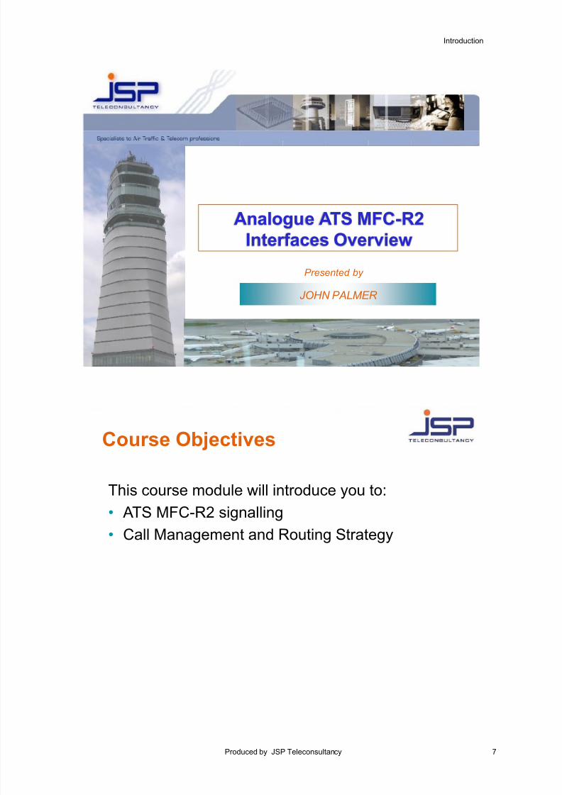
Course Objectives
This course module will introduce you to:
• ATS MFC-R2 signalling
• Call Management and Routing Strategy

7/18/2019 ATS MFC-R2 Analogue Signalling
http://slidepdf.com/reader/full/ats-mfc-r2-analogue-signalling 10/55
8 © Copyright 2014 JSP-Teleconsultancy
Analogue ATS MFC-R2 Analogue
interface
7/18/2019 ATS MFC-R2 Analogue Signalling
http://slidepdf.com/reader/full/ats-mfc-r2-analogue-signalling 11/55
ATS MFC-R2 Signalling
Produced by JSP Teleconsultancy 9
2. ATS MFC-R2 Signalling
7/18/2019 ATS MFC-R2 Analogue Signalling
http://slidepdf.com/reader/full/ats-mfc-r2-analogue-signalling 12/55
10 © Copyright 2014 JSP-Teleconsultancy
Analogue Signalling Types
Signalling Information
Signalling is a quite wide-ranging function of generating (sending) and recognising (receiving) signals. We canalso distinguish three types of signals: those related to the connection itself (seize, answer, release) known as
"Line signals" (supervisory), those related to the choosing the correct connection (proceed-to-send, digits, endof message), known as "Register Signals" and those related to the Switch's instructions to the user (normallythrough tones, i.e. dialling, busy, unobtainable tones) know as "User signals".
Three type of analogue signal exist:
1. Line Signals- related to the connection itself (e.g. Seize, answer and release (Clear-forward)
2. Register signals - related to choosing the correct connection (e.g. proceed to send, digits, end of message)
3. User signals - related to providing information to the user (e.g. dial tone, ringing tone, busy tone, congestiontone etc.)
What is compelled signalling ?
The Compelled signalling method operates as follows:
A signal is sent in the forward direction.
This signal is received and recognised and causes another signal to be sent as a response in the backwarddirection (can be used as an acknowledgement to the first signal).
As soon as this backward signal is received and recognised, then the forward signal is stopped.
As soon as it is recognised that the forward signal has stopped, the backwards signal is also stopped.
As soon as it has been recognised that the backwards signal has stopped, the appropriate next signal is sentin the forward direction and so the process goes on.
ATS MFC-R2 Register signalling is compelled. ITU-T No.5 Line signalling is compelled.
7/18/2019 ATS MFC-R2 Analogue Signalling
http://slidepdf.com/reader/full/ats-mfc-r2-analogue-signalling 13/55
ATS MFC-R2 Signalling
Produced by JSP Teleconsultancy 11
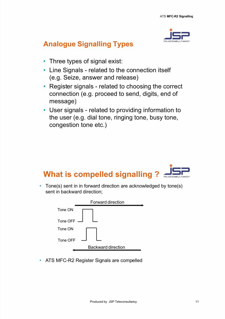
Analogue Signalling Types
• Three types of signal exist:
• Line Signals - related to the connection itself
(e.g. Seize, answer and release)
• Register signals - related to choosing the correct
connection (e.g. proceed to send, digits, end of
message)
• User signals - related to providing information tothe user (e.g. dial tone, ringing tone, busy tone,
congestion tone etc.)
What is compelled signalling ?
Forward direction
Backward direction
Tone ON
Tone OFF
Tone ON
Tone OFF
• Tone(s) sent in in forward direction are acknowledged by tone(s)
sent in backward direction;
• ATS MFC-R2 Register Signals are compelled
7/18/2019 ATS MFC-R2 Analogue Signalling
http://slidepdf.com/reader/full/ats-mfc-r2-analogue-signalling 14/55
12 © Copyright 2014 JSP-Teleconsultancy
A/B side configuration criteria
For each inter-VCS link within the AGVN employing either ATS-QSIG, ATS-R2 and ATS No.5 signallingprotocols, it should be possible to configure one VCS line interface as the "A" side and the other VCS lineinterface as the "B" side. The “A”/”B” side configuration is relative to the VCS line interface as opposed to thewhole VCS.
NOTE: Although there is no impact on the VCS itself, it is recommended that to ensure consistency within the AGVN the allocation of "A side and "B" side status on each link is based on the ICAO Location Indicators(ordered alphabetically) as illustrated in the slide.
7/18/2019 ATS MFC-R2 Analogue Signalling
http://slidepdf.com/reader/full/ats-mfc-r2-analogue-signalling 15/55
ATS MFC-R2 Signalling
Produced by JSP Teleconsultancy 13
MADRID
(LEAC)
LISBON
(Mil)(LPAM)
“A” side
“B” side “A” side
“B” side
“B” side
Bordeaux
(LFBD)
“A” side
Inter-VCS circuit
Inter-VCS circuitInter-VCS circuit
A/B side configuration criteria
• Each inter-VCS circuit has one VCS line interface configured as "A" sideand other as the "B" side.
• The “A”/”B” side configuration is relative to the VCS line interface as
opposed to whole VCS.
• Recommended that "A” side and "B" side status based on ICAO Location
Indicators (ordered alphabetically);
7/18/2019 ATS MFC-R2 Analogue Signalling
http://slidepdf.com/reader/full/ats-mfc-r2-analogue-signalling 16/55
14 © Copyright 2014 JSP-Teleconsultancy
ATS MFC-R2 Line Signalling (1)
Prior to the dialling of the number, a line on an available trunk shall be seized, and the receiving Switch shall beready to receive the incoming sequence of digits.
ATS MFC-R2 line signalling is a non-compelled inband signalling system, which implies that the signals are sentin a forward direction only and are not acknowledged. The Line signals are 2 280 Hz tones of fixed duration. ATS
MFC-R2 line signalling uses idle-tone off, which implies that when line is in the idle condition (i.e. not beingseized or involved in an active call), no signalling frequency is sent on the line.
For every ATS MFC-R2 link between two VCS systems, it is necessary to define one side as the “A” side and theother side as the “B” side. The duration of the line signal transmitted by the line circuit on one end shall be di fferentfrom that transmitted by the other end, e.g. Switch system A transmits a short line signal and Switch system Btransmits a long line signal. A short signal shall not be recognised when during the same time period a long signal hasbeen sent from Switch system B. Hence the signals from Switch system B will always dominate those from Switchsystem A.
It is possible to set each line circuit repeater within the VCS to long or short line signalling.
The line signals shall be recognised by the line signal receiver. Recognition times shall be considerably smaller thanthe line signal duration times.
The duration of line signals is defined in the table below:
Time in ms
Line Signal Side A Side B
Seizure 150 ± 25 350 ± 50
Clear-forward 400 ± 70 1 300 ± 200
Blocking 2 600 ± 550 4 800 ± 970
These values defined in the table above permit automatic compensation of short-term and long-term fluctuationsof the nominal signal duration.
7/18/2019 ATS MFC-R2 Analogue Signalling
http://slidepdf.com/reader/full/ats-mfc-r2-analogue-signalling 17/55
ATS MFC-R2 Signalling
Produced by JSP Teleconsultancy 15
ATS MFC-R2 Line Signalling (1)
• Line Signals include Seizure, Clear-forward and Blocking;
• Line Signalling: Non-Compelled Inband Signalling(i.e Signals sent in Forward direction and not acknowledged);
• Line Signalling frequency : 2280 Hz tone of fixed duration;
• Adjustable circuit repeater to long (B side) or short line (A side)
signalling;
• A and B side selection criteria based on geographical co-ordinates.
Relationship between Line Signal, Signal duration and A/B sides
2280Hz
LineSignal
(A side)
Seizure
Clear-forward
Blocking
(B side)
150ms +/- 25ms
400ms +/- 70ms
2600ms +/- 550ms
350ms +/- 50ms
1300ms +/- 200ms
4800ms +/- 970ms
7/18/2019 ATS MFC-R2 Analogue Signalling
http://slidepdf.com/reader/full/ats-mfc-r2-analogue-signalling 18/55
16 © Copyright 2014 JSP-Teleconsultancy
ATS MFC-R2 Line Signalling (2)
Line signals include:
Seizure: Is when a line circuit within the VCS is claimed for use by a terminal.
Clear-forward: Is when a line circuit within the VCS is stopped being used by the terminal, hence released in
order that it is available for another terminal to seize. Appropriate action from one terminal only, shall be sufficientto terminate a communication, to transmit the release signal and to release the line circuit within both systemswhich has been seized for the communication.
Blocking: when a line circuit is disconnected upon the arrival of a call with a higher priority level. This signal isalso used when the line is out-of-service (i.e. for failure or maintenance work), and has to be made unavailablefor seizure by users.
The 2280Hz tone of the Release and Blocking line signals i s cut off from the Controller’s headset somemilliseconds after the start of signal
Call Collision (Glare)
When two users on opposite ends of a link decide to make a call, it is possible that both ends could send theirseizing line signal simultaneously or within a finite period of each other on the same line. This phenomenon isknown as call collision, glare or double seizing.
Call collision is avoided by making the duration of the line signal transmitted by one line circuit on one end of thelink different from that transmitted by the other line circuit on the opposite end of the link e.g. Switch system Atransmits a short line signal and Switch system B transmits a long line signal. A short signal shall not berecognised when during the same time period a long signal has been sent from Switch system B.
If call collision occurs the calling terminal of Switch system A shall receive a busy signal in this event and eitherautomatic call repetition is initiated or the system selects another circuit.
As a first step to prevent call collision, the selection of the circuits in a trunk shall be so arranged that at oneSwitch (nominated “A” side), selection is performed in an 'upwards-counting' order (i.e. from circuit one upwards)and at the other Switch (nominated “B” side) it is performed in a 'downwards-counting' order (i.e. from circuit ndown to circuit one).
7/18/2019 ATS MFC-R2 Analogue Signalling
http://slidepdf.com/reader/full/ats-mfc-r2-analogue-signalling 19/55
ATS MFC-R2 Signalling
Produced by JSP Teleconsultancy 17
ATS MFC-R2 Line Signalling (2)
• SEIZURE : to “take a line circuit”
Provisions against CALL COLLISION are needed :
Each trunk is allocated as a A or B side having different signal
durations : B will always gain access
Trunk selection starts in reverse order (A side = counts upagainst B side = counts down);
• CLEAR-FORWARD: to release the circuit : different signal durations for A & B
RELEASE : action of A or B side is sufficient;
• BLOCKING: disconnects circuit in congested link to allows higher priorityto proceed:
Different signal duration for A & B sides; can be sent in forward orbackward directions; also used to place line in “out of service” conditionfor maintenance reasons;
• The 2280Hz tone of Clear-forward and Blocking line signals is cut off from the
operator’s headset some milliseconds after start of signal
7/18/2019 ATS MFC-R2 Analogue Signalling
http://slidepdf.com/reader/full/ats-mfc-r2-analogue-signalling 20/55
18 © Copyright 2014 JSP-Teleconsultancy
ATS MFC-R2 Register Signalling - Numerical information
The ATS MFC-R2 Numerical signals are register signals and are sent to the VCS when numbers are dialled or a"Direct Access" key has been pressed. When making a call, there is a 13 digit numerical signal transmitted to theVCS system. This is comprised of the 6 dialled digits for the destination address (called party number), 1 digit forcall priority level and 6 digits added representing the source address (calling party number).
The ATS MFC-R2 signalling makes use of two groups of five frequencies, one group in an upper frequency bandand the other group in a lower frequency band, within the available bandwidth of the voice channel. Signallingshall be performed by simultaneously sending two out of the five frequencies available, according to the codinggiven in the following tables.
The MFC-R2 signals are exchanged according to a compelled procedure. This implies that each digit transmittedin a forward direction using the Upper Frequency band shall be acknowledged by re-transmissions of the samedigit in the Lower Frequency band in a backwards direction.
In the case of a fault or no acknowledgement signal at all, the signalling procedure shall be stopped and the calling system shalltransmit the line signal 'release'.
The Composition of the MFC code is defined in the following table.
Frequency in Hz
Upper FrequencyBand
ForwardDirection
1 380 1 500 1 620 1 740 1 860
Lower FrequencyBand
BackwardDirection
1 140 1 020 900 780 660
Weight 0 1 2 4 7
No. Numerical Value
1 0+1 x x
2 0+2 x x
3 1+2 x x
4 0+4 x x
5 1+4 x x
6 2+4 x x
7 0+7 x x
8 1+7 x x
9 2+7 x x
0 4+7 x x
7/18/2019 ATS MFC-R2 Analogue Signalling
http://slidepdf.com/reader/full/ats-mfc-r2-analogue-signalling 21/55
ATS MFC-R2 Signalling
Produced by JSP Teleconsultancy 19
The Relationship between Numerical digit and Frequencies is defined in the following table:
Frequency in Hz
NumericalDigit
Calling Frequencies
(Forward Direction)
Acknowledging Frequencies
(Backward Direction)
1 1 380 1 500 1 140 1 020
2 1 380 1 620 1 140 900
3 1 500 1 620 1 020 900
4 1 380 1 740 1 140 780
5 1 500 1 740 1 020 780
6 1 620 1 740 900 780
7 1 380 1 860 1 140 660
8 1 500 1 860 1 020 660
9 1 620 1 860 900 660
0 1 740 1 860 780 660
ATS MFC-R2 Register Signalling -
Numerical information
• Compelled Inband Signalling system is used for Register Signalling ofthe numerical digit information (i.e. Number dialled).
• 2 groups of 5 frequencies; Number represented by 2 of 5 frequencies;
No. Calling Frequencies(Forward direction)
Acknowledgement Frequencies(Backward direction)
1 1380 1500 1140 1020
2 1380 1620 1140 900
3 1500 1620 1020 900
4 1380 1740 1140 780
5 1500 1740 1020 7806 1620 1740 900 780
7 1380 1860 1140 660
8 1500 1860 1020 660
9 1620 1860 900 660
0 1740 1860 780 660
Relationship between numerical information and Frequencies
7/18/2019 ATS MFC-R2 Analogue Signalling
http://slidepdf.com/reader/full/ats-mfc-r2-analogue-signalling 22/55
20 © Copyright 2014 JSP-Teleconsultancy
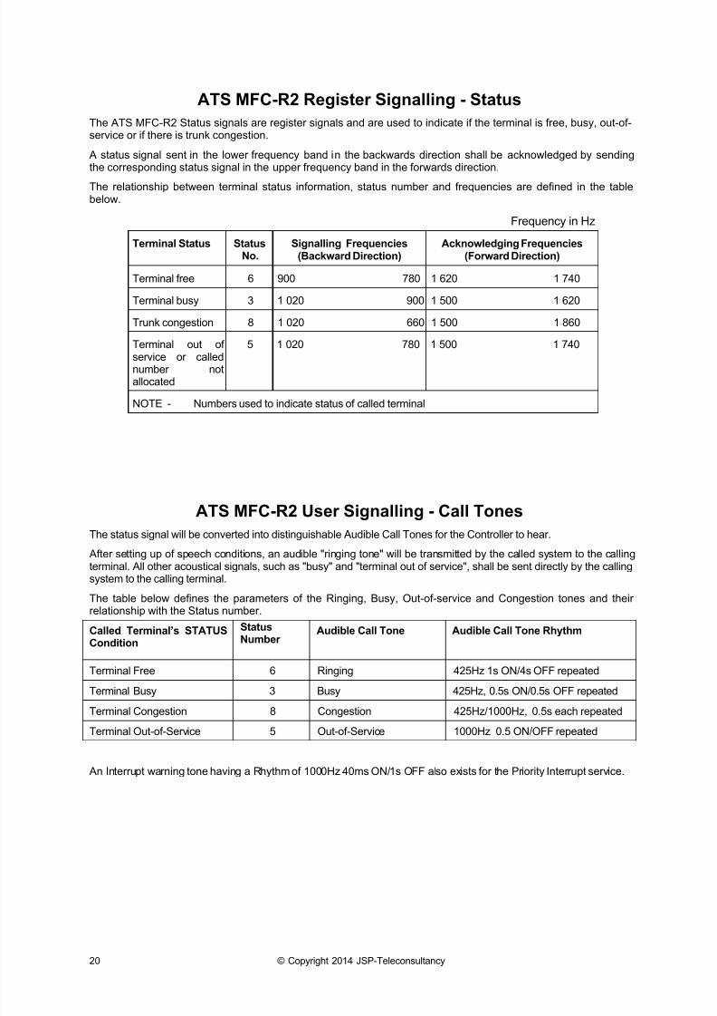
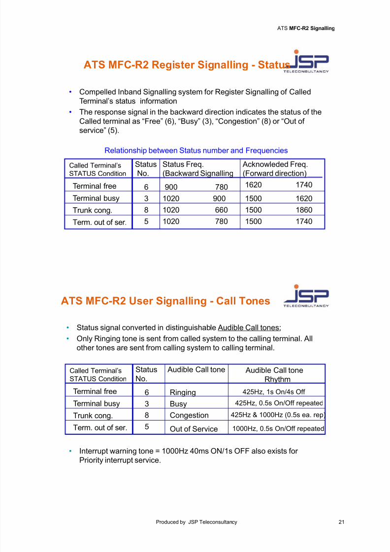
ATS MFC-R2 Register Signalling - Status
The ATS MFC-R2 Status signals are register signals and are used to indicate if the terminal is free, busy, out-of-service or if there is trunk congestion.
A status signal sent in the lower frequency band in the backwards direction shall be acknowledged by sendingthe corresponding status signal in the upper frequency band in the forwards direction.
The relationship between terminal status information, status number and frequencies are defined in the tablebelow.
Frequency in Hz
Terminal Status StatusNo.
Signalling Frequencies(Backward Direction)
Acknowledging Frequencies(Forward Direction)
Terminal free 6 900 780 1 620 1 740
Terminal busy 3 1 020 900 1 500 1 620
Trunk congestion 8 1 020 660 1 500 1 860
Terminal out of
service or callednumber notallocated
5 1 020 780 1 500 1 740
NOTE - Numbers used to indicate status of called terminal
ATS MFC-R2 User Signalling - Call Tones
The status signal will be converted into distinguishable Audible Call Tones for the Controller to hear.
After setting up of speech conditions, an audible "ringing tone" will be transmitted by the called system to the callingterminal. All other acoustical signals, such as "busy" and "terminal out of service", shall be sent directly by the callingsystem to the calling terminal.
The table below defines the parameters of the Ringing, Busy, Out-of-service and Congestion tones and theirrelationship with the Status number.
Called Terminal’s STATUS
Condition
StatusNumber
Audible Call Tone Audible Call Tone Rhythm
Terminal Free 6 Ringing 425Hz 1s ON/4s OFF repeated
Terminal Busy 3 Busy 425Hz, 0.5s ON/0.5s OFF repeated
Terminal Congestion 8 Congestion 425Hz/1000Hz, 0.5s each repeated
Terminal Out-of-Service 5 Out-of-Service 1000Hz 0.5 ON/OFF repeated
An Interrupt warning tone having a Rhythm of 1000Hz 40ms ON/1s OFF also exists for the Priority Interrupt service.
7/18/2019 ATS MFC-R2 Analogue Signalling
http://slidepdf.com/reader/full/ats-mfc-r2-analogue-signalling 23/55
ATS MFC-R2 Signalling
Produced by JSP Teleconsultancy 21
ATS MFC-R2 Register Signalling - Status
• Compelled Inband Signalling system for Register Signalling of Called
Terminal’s status information
• The response signal in the backward direction indicates the status of the
Called terminal as “Free” (6), “Busy” (3), “Congestion” (8) or “Out of
service” (5).
Relationship between Status number and Frequencies
Status
No.
Status Freq.
(Backward Signalling
Acknowleded Freq.
(Forward direction)
Terminal free 6 900 780
Terminal busy 3 1020 900
Trunk cong. 8 1020 660
Term. out of ser. 5 1020 780
1620 1740
1500 1620
1500 1860
1500 1740
Called Terminal’s
STATUS Condition
ATS MFC-R2 User Signalling - Call Tones
• Status signal converted in distinguishable Audible Call tones;
• Only Ringing tone is sent from called system to the calling terminal. All
other tones are sent from calling system to calling terminal.
Status
No. Audible Call tone
Rhythm
Terminal free 6 425Hz, 1s On/4s Off
Terminal busy 3 425Hz, 0.5s On/Off repeated
Trunk cong. 8 425Hz & 1000Hz (0.5s ea. rep)
Term. out of ser. 5 1000Hz, 0.5s On/Off repeated
Called Terminal’s
STATUS Condition
Audible Call tone
Ringing
Busy
Congestion
Out of Service
• Interrupt warning tone = 1000Hz 40ms ON/1s OFF also exists for
Priority interrupt service.
7/18/2019 ATS MFC-R2 Analogue Signalling
http://slidepdf.com/reader/full/ats-mfc-r2-analogue-signalling 24/55
22 © Copyright 2014 JSP-Teleconsultancy
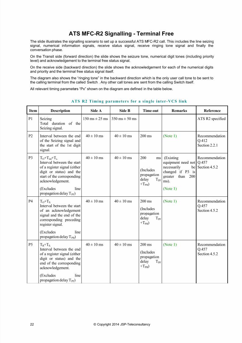
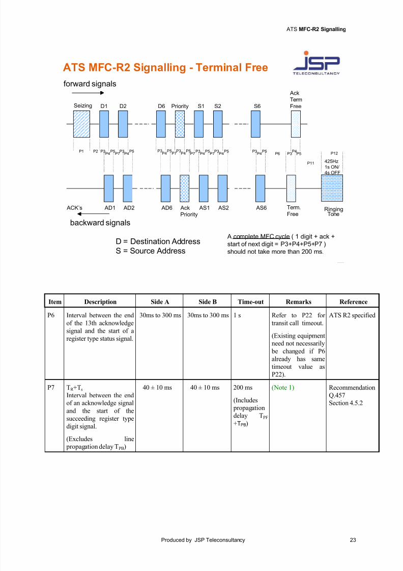
ATS MFC-R2 Signalling - Terminal Free
The slide illustrates the signalling scenario to set up a successful ATS MFC-R2 call. This includes the line seizingsignal, numerical information signals, receive status signal, receive ringing tone signal and finally theconversation phase.
On the Transit side (forward direction) the slide shows the seizure tone, numerical digit tones (including priority
level) and acknowledgement to the terminal free status signal.
On the receive side (backward direction) the slide shows the acknowledgement for each of the numerical digitsand priority and the terminal free status signal itself.
The diagram also shows the “ringing tone” in the backward direction which is the only user call tone to be sent tothe calling terminal from the called Switch . Any other call tones are sent from the calling Switch itself.
All relevant timing parameters “Px” shown on the diagram are defined in the table below.
ATS R2 Timing parameters for a s ingle inter-VCS link
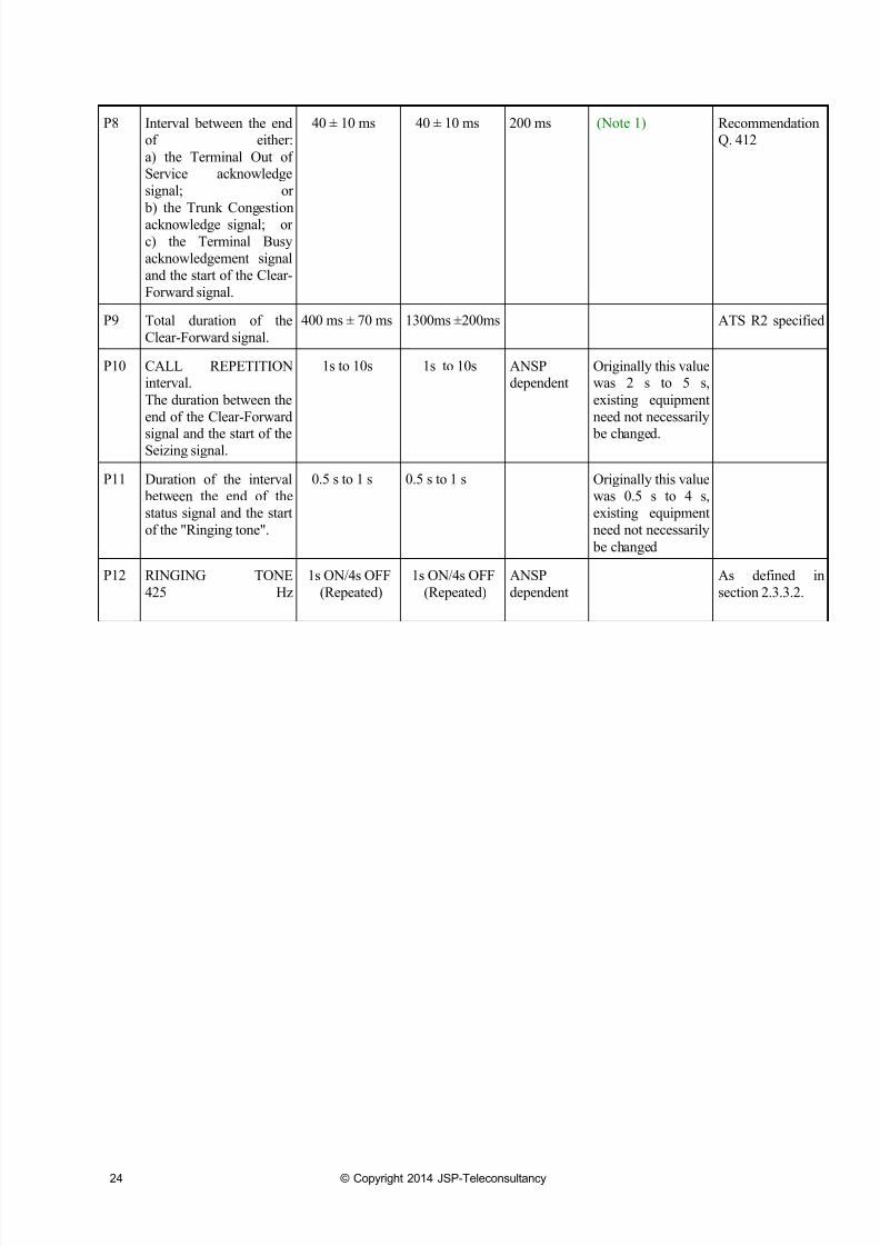
Item Description Side A Side B Time-out Remarks Reference
P1 SeizingTotal duration of the
Seizing signal.
150 ms ± 25 ms 350 ms ± 50 ms ATS R2 specified
P2 Interval between the end
of the Seizing signal and
the start of the 1st digit
signal.
40 ± 10 ms 40 ± 10 ms 200 ms (Note 1) Recommendation
Q.412
Section 2.2.1
P3 TO+Tint+Ts.
Interval between the start
of a register signal (either
digit or status) and the
start of the corresponding
acknowledgement.
(Excludes line
propagation delay TPF)
40 ± 10 ms 40 ± 10 ms 200 ms
(Includes
propagation
delay TPF+TPB)
(Existingequipment need not
necessarily be
changed if P3 is
greater than 200
ms).
(Note 1)
RecommendationQ.457
Section 4.5.2
P4 TO+TS.
Interval between the start
of an acknowledgement
signal and the end of thecorresponding preceding
register signal.
(Excludes line
propagation delay TPB)
40 ± 10 ms 40 ± 10 ms 200 ms
(Includes
propagation
delay TPF
+TPB)
(Note 1) RecommendationQ.457
Section 4.5.2
P5 TR +TS.
Interval between the end
of a register signal (either
digit or status) and the
end of the corresponding
acknowledgement.
(Excludes line
propagation delay TPF)
40 ± 10 ms 40 ± 10 ms 200 ms
(Includes
propagationdelay TPF
+TPB)
(Note 1) Recommendation
Q.457
Section 4.5.2
7/18/2019 ATS MFC-R2 Analogue Signalling
http://slidepdf.com/reader/full/ats-mfc-r2-analogue-signalling 25/55
ATS MFC-R2 Signalling
Produced by JSP Teleconsultancy 23
Item Description Side A Side B Time-out Remarks Reference
P6 Interval between the end
of the 13th acknowledge
signal and the start of a
register type status signal.
30ms to 300 ms 30ms to 300 ms 1 s Refer to P22 for
transit call timeout.
(Existing equipmentneed not necessarily
be changed if P6
already has same
timeout value as
P22).
ATS R2 specified
P7 TR +Ts
Interval between the end
of an acknowledge signaland the start of the
succeeding register type
digit signal.
(Excludes line propagation delay TPB)
40 ± 10 ms 40 ± 10 ms 200 ms
(Includes propagation
delay TPF
+TPB)
(Note 1) Recommendation
Q.457
Section 4.5.2
ATS MFC-R2 Signalling - Terminal Free
D = Destination Address
S = Source Address
A complete MFC cycle ( 1 digit + ack +
start of next digit = P3+P4+P5+P7 )
should not take more than 200 ms.
forward signals
backward signals
D1 D2 D6 Priority S1 S2 S6
P1 P2
Term.
Free AD1 AD2 AD6 Ack
Priority
AS1 AS2 AS6
Ack
TermFree
ACK’s
Seizing
P3P4
P5P7
P3P4
P5P7 P6 P3
P4P5P4
P5P7
P3P4
P5P3P4
P5P7
P3P4
P5P3 P3P4
P5
RingingTone
P12
P11 425Hz
1s ON/
4s OFF
7/18/2019 ATS MFC-R2 Analogue Signalling
http://slidepdf.com/reader/full/ats-mfc-r2-analogue-signalling 26/55
24 © Copyright 2014 JSP-Teleconsultancy
P8 Interval between the endof either:
a) the Terminal Out ofService acknowledge
signal; or
b) the Trunk Congestion
acknowledge signal; or
c) the Terminal Busy
acknowledgement signal
and the start of the Clear-
Forward signal.
40 ± 10 ms 40 ± 10 ms 200 ms (Note 1) RecommendationQ. 412
P9 Total duration of the
Clear-Forward signal.
400 ms ± 70 ms 1300ms ±200ms ATS R2 specified
P10 CALL REPETITIONinterval.
The duration between the
end of the Clear-Forward
signal and the start of theSeizing signal.
1s to 10s 1s to 10s ANSPdependent
Originally this valuewas 2 s to 5 s,
existing equipment
need not necessarily
be changed.
P11 Duration of the interval between the end of the
status signal and the start
of the "Ringing tone".
0.5 s to 1 s 0.5 s to 1 s Originally this valuewas 0.5 s to 4 s,
existing equipment
need not necessarily
be changed
P12 RINGING TONE
425 Hz
1s ON/4s OFF
(Repeated)
1s ON/4s OFF
(Repeated)
ANSP
dependent
As defined in
section 2.3.3.2.
7/18/2019 ATS MFC-R2 Analogue Signalling
http://slidepdf.com/reader/full/ats-mfc-r2-analogue-signalling 27/55
ATS MFC-R2 Signalling
Produced by JSP Teleconsultancy 25
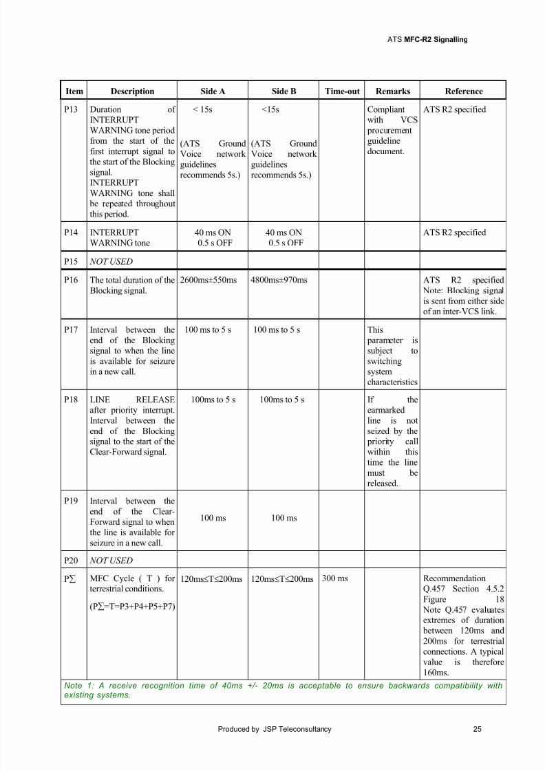
Item Description Side A Side B Time-out Remarks Reference
P13 Duration of
INTERRUPT
WARNING tone period
from the start of the
first interrupt signal to
the start of the Blocking
signal.INTERRUPT
WARNING tone shall
be repeated throughout
this period.
< 15s
(ATS GroundVoice network
guidelines
recommends 5s.)
<15s
(ATS GroundVoice network
guidelines
recommends 5s.)
Compliant
with VCS
procurement
guideline
document.
ATS R2 specified
P14 INTERRUPTWARNING tone
40 ms ON0.5 s OFF
40 ms ON0.5 s OFF
ATS R2 specified
P15 NOT USED
P16 The total duration of the
Blocking signal.
2600ms±550ms 4800ms±970ms ATS R2 specified
Note: Blocking signal
is sent from either side
of an inter-VCS link.
P17 Interval between the
end of the Blocking
signal to when the line
is available for seizure
in a new call.
100 ms to 5 s 100 ms to 5 s This
parameter is
subject to
switching
system
characteristics
P18 LINE RELEASEafter priority interrupt.
Interval between the
end of the Blockingsignal to the start of the
Clear-Forward signal.
100ms to 5 s 100ms to 5 s If theearmarked
line is not
seized by the priority call
within this
time the line
must be
released.
P19 Interval between the
end of the Clear-
Forward signal to when
the line is available for
seizure in a new call.
100 ms 100 ms
P20 NOT USED
P MFC Cycle ( T ) forterrestrial conditions.
(P=T=P3+P4+P5+P7)
120msT200ms 120msT200ms 300 ms RecommendationQ.457 Section 4.5.2
Figure 18
Note Q.457 evaluatesextremes of duration
between 120ms and
200ms for terrestrial
connections. A typical
value is therefore
160ms.Note 1: A receive recognition time of 40ms +/- 20ms is acceptable to ensure backwards compatibility withexisting systems.
7/18/2019 ATS MFC-R2 Analogue Signalling
http://slidepdf.com/reader/full/ats-mfc-r2-analogue-signalling 28/55
26 © Copyright 2014 JSP-Teleconsultancy
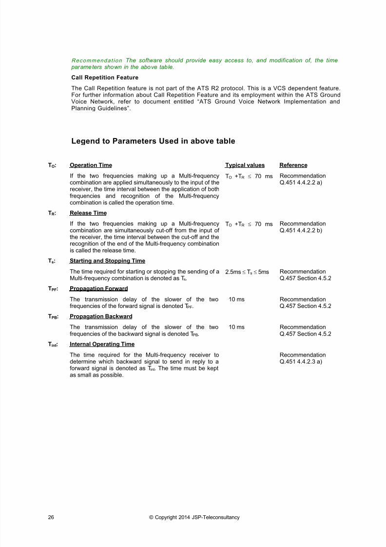
Recommenda t i on The software should provide easy access to, and modification of, the time parameters shown in the above table.
Call Repetition Feature
The Call Repetition feature is not part of the ATS R2 protocol. This is a VCS dependent feature.
For further information about Call Repetition Feature and its employment within the ATS GroundVoice Network, refer to document entitled “ATS Ground Voice Network Implementation andPlanning Guidelines”.
Legend to Parameters Used in above table
TO: Operation Time Typical values Reference
If the two frequencies making up a Multi-frequencycombination are applied simultaneously to the input of the
receiver, the time interval between the application of bothfrequencies and recognition of the Multi-frequencycombination is called the operation time.
TO +TR 70 ms RecommendationQ.451 4.4.2.2 a)
TR: Release Time
If the two frequencies making up a Multi-frequencycombination are simultaneously cut-off from the input ofthe receiver, the time interval between the cut-off and therecognition of the end of the Multi-frequency combinationis called the release time.
TO +TR 70 ms RecommendationQ.451 4.4.2.2 b)
Ts: Starting and Stopping Time
The time required for starting or stopping the sending of aMulti-frequency combination is denoted as Ts.
2.5ms Ts 5ms RecommendationQ.457 Section 4.5.2
TPF: Propagation Forward
The transmission delay of the slower of the twofrequencies of the forward signal is denoted TPF.
10 ms RecommendationQ.457 Section 4.5.2
TPB: Propagation Backward
The transmission delay of the slower of the twofrequencies of the backward signal is denoted TPB.
10 ms RecommendationQ.457 Section 4.5.2
Tint: Internal Operating Time
The time required for the Multi-frequency receiver todetermine which backward signal to send in reply to aforward signal is denoted as Tint. The time must be keptas small as possible.
RecommendationQ.451 4.4.2.3 a)

7/18/2019 ATS MFC-R2 Analogue Signalling
http://slidepdf.com/reader/full/ats-mfc-r2-analogue-signalling 29/55
ATS MFC-R2 Signalling
Produced by JSP Teleconsultancy 27
This page is intentionally blank.
7/18/2019 ATS MFC-R2 Analogue Signalling
http://slidepdf.com/reader/full/ats-mfc-r2-analogue-signalling 30/55
28 © Copyright 2014 JSP-Teleconsultancy
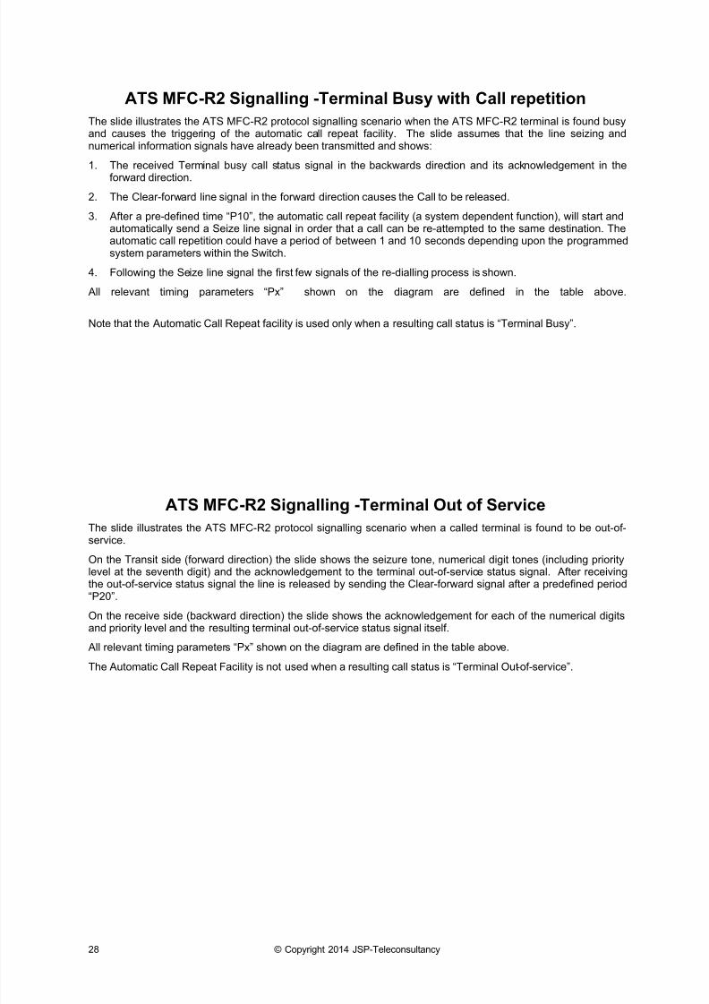
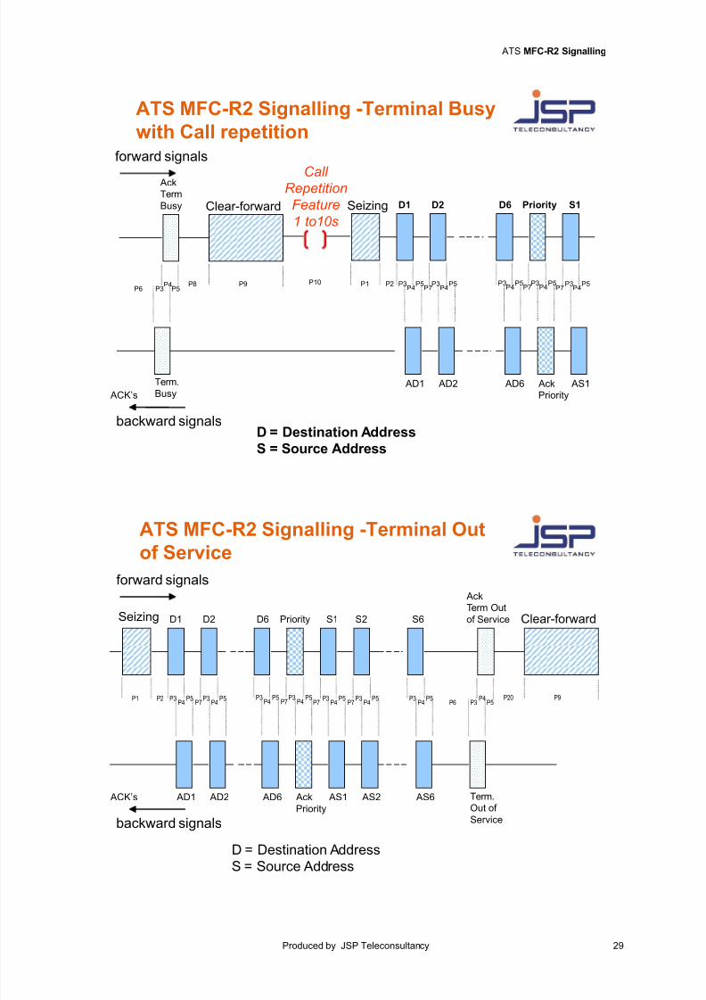
ATS MFC-R2 Signalling -Terminal Busy with Call repetition
The slide illustrates the ATS MFC-R2 protocol signalling scenario when the ATS MFC-R2 terminal is found busyand causes the triggering of the automatic call repeat facility. The slide assumes that the line seizing andnumerical information signals have already been transmitted and shows:
1. The received Terminal busy call status signal in the backwards direction and its acknowledgement in the
forward direction.
2. The Clear-forward line signal in the forward direction causes the Call to be released.
3. After a pre-defined time “P10”, the automatic call repeat facility (a system dependent function), will start andautomatically send a Seize line signal in order that a call can be re-attempted to the same destination. Theautomatic call repetition could have a period of between 1 and 10 seconds depending upon the programmedsystem parameters within the Switch.
4. Following the Seize line signal the first few signals of the re-dialling process is shown.
All relevant timing parameters “Px” shown on the diagram are defined in the table above.
Note that the Automatic Call Repeat facility is used only when a resulting call status is “Terminal Busy”.
ATS MFC-R2 Signalling -Terminal Out of Service
The slide illustrates the ATS MFC-R2 protocol signalling scenario when a called terminal is found to be out-of-service.
On the Transit side (forward direction) the slide shows the seizure tone, numerical digit tones (including prioritylevel at the seventh digit) and the acknowledgement to the terminal out-of-service status signal. After receivingthe out-of-service status signal the line is released by sending the Clear-forward signal after a predefined period“P20”.
On the receive side (backward direction) the slide shows the acknowledgement for each of the numerical digitsand priority level and the resulting terminal out-of-service status signal itself.
All relevant timing parameters “Px” shown on the diagram are defined in the table above.
The Automatic Call Repeat Facility is not used when a resulting call status is “Terminal Out-of-service”.
7/18/2019 ATS MFC-R2 Analogue Signalling
http://slidepdf.com/reader/full/ats-mfc-r2-analogue-signalling 31/55
ATS MFC-R2 Signalling
Produced by JSP Teleconsultancy 29
ATS MFC-R2 Signalling -Terminal Busy
with Call repetitionforward signals
backward signals
Term.
Busy
Ack
Term
Busy
ACK’s
P6 P3P4
P5P8 P9
Clear-forward D1 D2 D6 Priority S1
P1 P2
AD1 AD2 AD6 Ack
Priority
AS1
Seizing
P3P4
P5P7
P3P4
P5P7P4
P5P7
P3P4
P5P3P4
P5P3P10
Call Repetition
Feature
1 to10s
D = Destination Address
S = Source Address
ATS MFC-R2 Signalling -Terminal Outof Service
forward signals
backward signals
D1 D2 D6 Priority S1 S2 S6
P1 P2
Term.
Out of
Service
AD1 AD2 AD6 Ack
Priority
AS1 AS2 AS6
Ack
Term Out
of Service
ACK’s
Seizing
P3P4
P5P7
P3P4
P5P7 P6 P3
P4P5P4
P5
P7
P3
P4
P5P3
P4 P5
P7P3
P4 P5P3 P3
P4 P5
D = Destination Address
S = Source Address
P20 P9
Clear-forward
7/18/2019 ATS MFC-R2 Analogue Signalling
http://slidepdf.com/reader/full/ats-mfc-r2-analogue-signalling 32/55
30 © Copyright 2014 JSP-Teleconsultancy
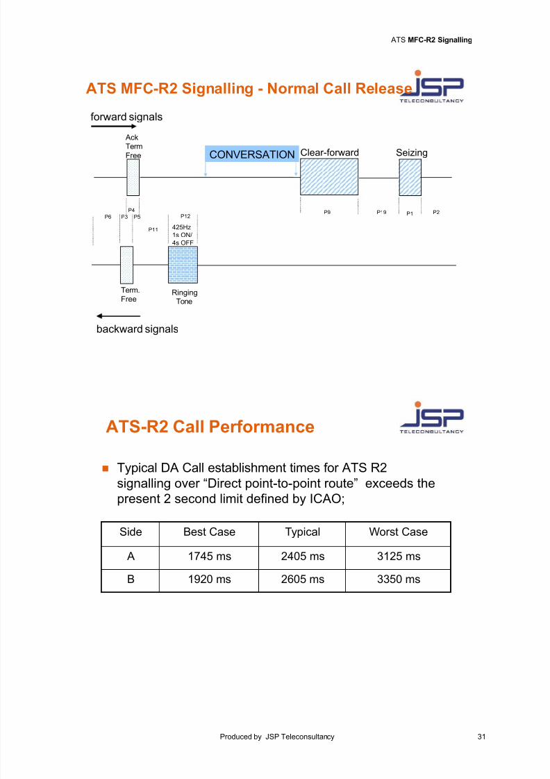
ATS MFC-R2 Signalling - Normal Call Release
The slide illustrates the ATS MFC-R2 protocol signalling scenario for a normal call release. The slide assumesthat the line seizing and numerical information signals have already been transmitted and shows:
1. The received Terminal free status signal in the backwards direction and its acknowledgement in the forwarddirection.
2. The “Ringing Tone” in the backwards direction, which is 1s ON/4s OFF until the call is answered or the Alerting timeout has expired.
3. The Conversation phase (assuming the call is answered);
4. When one of the users in the conversation decides to terminate the call, a Clear-forward Line signal in theforward direction causes the Call to be released.
5. A predefined period “P19” must expire before the line is considered available by the system for another lineseizure.
All relevant timing parameters “Px” shown on the diagram are defined in the table above.
ATS-R2 Call Performance
Call Performance Measurements for Analogue signalling
For example an analogue AGVN using ATS R2 interfaces and employing the ATS R2 signallingsystem as defined in the Eurocontrol “ATS R2 and ATS No.5 protocol specification”, has its callestablishment times on a single inter-VCS link defined in the table below. Call establishment timevaries according whether a call is made from an “A” side or a “B” side of the link and on the timinginterval tolerance associated with each tone.
Call establishment times relative to A/B sides and timing tolerance using ATS R2 signallingsystem
Side Best Case Typical Worst Case
A 1745 ms 2405 ms 3125 ms
B 1920 ms 2605 ms 3350 ms
From the Table above it can be seen that the typical call establishment times are 23405ms and2605ms for A and B sides respectively. These values exceed the present ICAO 2 second limit.
7/18/2019 ATS MFC-R2 Analogue Signalling
http://slidepdf.com/reader/full/ats-mfc-r2-analogue-signalling 33/55
ATS MFC-R2 Signalling
Produced by JSP Teleconsultancy 31
ATS MFC-R2 Signalling - Normal Call Release
forward signals
backward signals
Term.
Free
AckTerm
Free
P6 P3
P4
P5
RingingTone
P12
P11 425Hz
1s ON/
4s OFF
CONVERSATION
P9 P1
Seizing
P19 P2
Clear-forward
ATS-R2 Call Performance
Side Best Case Typical Worst Case
A 1745 ms 2405 ms 3125 ms
B 1920 ms 2605 ms 3350 ms
Typical DA Call establishment times for ATS R2
signalling over “Direct point-to-point route” exceeds the
present 2 second limit defined by ICAO;
7/18/2019 ATS MFC-R2 Analogue Signalling
http://slidepdf.com/reader/full/ats-mfc-r2-analogue-signalling 34/55
32 © Copyright 2014 JSP-Teleconsultancy
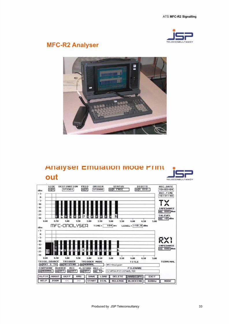
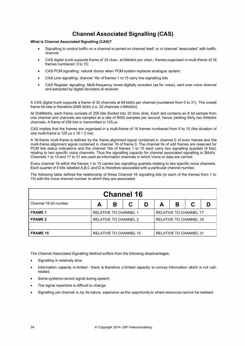
MFC-R2 Analyser
Analyser Emulation Mode Print out
The Slide provides an example of ATS MFC-R2 incoming call towards the MFC-R2 analyser (configured forEmulation mode and as an A side). The compelled signalling procedure of the calling party address, priority digitand called party address can be observed. The status signal 6 (Terminal Free) is returned by the Tester and thisis acknowledged by the B side system. When the call is answered, two-way speech is possible.
It can be observed that the incoming Line Signal level of the Seizure Signal from the B side is -12dBm. It can beobserved that the incoming Register tone pairs from the B side have a level of -9dBm.
The Register signal level is always 3dBm higher than the Line signal level. This is because the Register signallevel is indicated as the sum of the levels from the tone pair, which is equivalent to adding 3dBm to the line signallevel.
Therefore when measuring the actual incoming or outgoing l ine signal level i t is necessary to observe the level ofa line signal (i.e. Seizure, Release or Blocking) as opposed to a Register signal.
7/18/2019 ATS MFC-R2 Analogue Signalling
http://slidepdf.com/reader/full/ats-mfc-r2-analogue-signalling 35/55
ATS MFC-R2 Signalling
Produced by JSP Teleconsultancy 33
MFC-R2 Analyser
out
7/18/2019 ATS MFC-R2 Analogue Signalling
http://slidepdf.com/reader/full/ats-mfc-r2-analogue-signalling 36/55
34 © Copyright 2014 JSP-Teleconsultancy
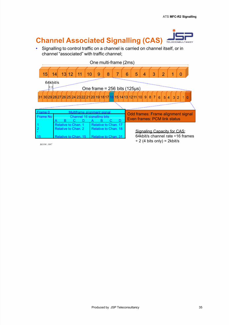
Channel Associated Signalling (CAS)
What is Channel Associated Signalling (CAS)?
Signalling to control traffic on a channel is carried on channel itself, or in channel “associated” with trafficchannel;
CAS digital trunk supports frame of 32 chan. at 64kbit/s per chan.; frames organised in multi-frame of 16frames numbered: 0 to 15;
CAS PCM signalling: natural choice when PCM system replaces analogue system;
CAS Line signalling: channel 16s of frames 1 to 15 carry line signalling bits
CAS Register signalling: Multi-frequency tones digitally encoded (as for voice), sent over voice channeland extracted by digital decoders at receiver;
A CAS digital trunk supports a frame of 32 channels at 64 kbit/s per channel (numbered from 0 to 31). The overallframe bit rate is therefore 2048 kbit/s (i.e. 32 channels x 64kbit/s).
At 2048kbit/s, each frame consists of 256 bits divided into 32 time slots. Each slot contains an 8 bit sample fromone channel and channels are sampled at a rate of 8000 samples per second, hence yielding thirty two 64kbit/s
channels. A frame of 256 bits is transmitted in 125 s.
CAS implies that the frames are organised in a multi-frame of 16 frames numbered from 0 to 15 (the duration of
one multi-frame is 125 s x 16 = 2 ms)
A 16-frame multi-frame is defined by the frame alignment signal contained in channel 0 of even frames and themulti-frame alignment signal contained in channel 16 of frame 0. The channel 0s of odd frames are reserved forPCM link status indications and the channel 16s of frames 1 to 15 each carry two signalling quartets (4 bits)relating to two specific voice channels. Thus the signalling capacity for channel associated signalling is 2kbit/s.Channels 1 to 15 and 17 to 31 are used as information channels in which Voice or data are carried.
Every channel 16 within the frames 1 to 15 carries two signalling quartets relating to two specific voice channels.Each quartet of 4 bits labelled A,B,C and D is therefore associated with a particular channel number.
The following table defines the relationship of these Channel 16 signalling bits (in each of the frames from 1 to15) with the voice channel number to which they are associated.
Channel 16Channel 16 bit number A B C D A B C D
FRAME 1 RELATIVE TO CHANNEL 1 RELATIVE TO CHANNEL 17
FRAME 2 RELATIVE TO CHANNEL 2 RELATIVE TO CHANNEL 18
FRAME 15 RELATIVE TO CHANNEL 15 RELATIVE TO CHANNEL 31
The Channel Associated Signalling Method suffers from the following disadvantages:
Signalling is relatively slow.
Information capacity is limited - there is therefore a limited capacity to convey information which is not call-related.
Some systems cannot signal during speech
The signal repertoire is difficult to change
Signalling per channel is, by its nature, expensive as the opportunity to share resources cannot be realised.
7/18/2019 ATS MFC-R2 Analogue Signalling
http://slidepdf.com/reader/full/ats-mfc-r2-analogue-signalling 37/55
ATS MFC-R2 Signalling
Produced by JSP Teleconsultancy 35
Channel Associated Signalling (CAS)
BO190_1097
One multi-frame (2ms)
15 14 13 12 11 10 9 8 7 6 5 4 3 2 1 0
One frame = 256 bits (125µs)
Odd frames: Frame alignment signalEven frames: PCM link status
012345678910111213141516171819202122232425262728293031
64kbit/s
Signaling Capacity for CAS:
64kbit/s channel rate 16 frames
2 (4 bits only) = 2kbit/s
Frame 0 Multiframe alignment signalFrame No Channel 16 signalling bits A B C D A B C D
1 Relative to Chan. 1 Relative to Chan. 172 Relative to Chan. 2 Relative to Chan. 18"15 Relative to Chan. 15 Relative to Chan. 31
• Signalling to control traffic on a channel is carried on channel itself, or in
channel “associated” with traffic channel;

7/18/2019 ATS MFC-R2 Analogue Signalling
http://slidepdf.com/reader/full/ats-mfc-r2-analogue-signalling 38/55
36 © Copyright 2014 JSP-Teleconsultancy
Analogue ATS MFC-R2 Analogue
interface
7/18/2019 ATS MFC-R2 Analogue Signalling
http://slidepdf.com/reader/full/ats-mfc-r2-analogue-signalling 39/55
Call Management and Routing Strategy
Produced by JSP Teleconsultancy 37
3. Call Management and Routing Strategy
7/18/2019 ATS MFC-R2 Analogue Signalling
http://slidepdf.com/reader/full/ats-mfc-r2-analogue-signalling 40/55
38 © Copyright 2014 JSP-Teleconsultancy
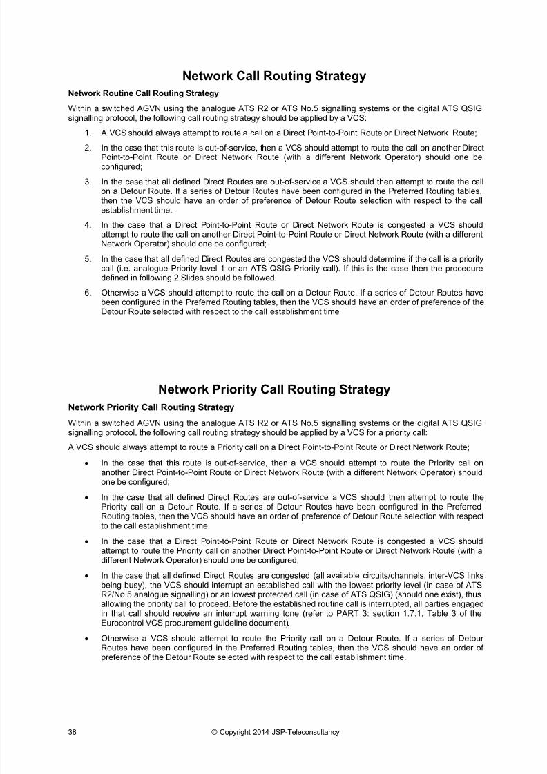
Network Call Routing Strategy
Network Routine Call Routing Strategy
Within a switched AGVN using the analogue ATS R2 or ATS No.5 signalling systems or the digital ATS QSIGsignalling protocol, the following call routing strategy should be applied by a VCS:
1. A VCS should always attempt to route a call on a Direct Point-to-Point Route or Direct Network Route;2. In the case that this route is out-of-service, then a VCS should attempt to route the call on another Direct
Point-to-Point Route or Direct Network Route (with a different Network Operator) should one beconfigured;
3. In the case that all defined Direct Routes are out-of-service a VCS should then attempt to route the callon a Detour Route. If a series of Detour Routes have been configured in the Preferred Routing tables,then the VCS should have an order of preference of Detour Route selection with respect to the callestablishment time.
4. In the case that a Direct Point-to-Point Route or Direct Network Route is congested a VCS shouldattempt to route the call on another Direct Point-to-Point Route or Direct Network Route (with a differentNetwork Operator) should one be configured;
5. In the case that all defined Direct Routes are congested the VCS should determine if the call is a priority
call (i.e. analogue Priority level 1 or an ATS QSIG Priority call). If this is the case then the proceduredefined in following 2 Slides should be followed.
6. Otherwise a VCS should attempt to route the call on a Detour Route. If a series of Detour Routes havebeen configured in the Preferred Routing tables, then the VCS should have an order of preference of theDetour Route selected with respect to the call establishment time
Network Priority Call Routing Strategy
Network Priority Call Routing Strategy
Within a switched AGVN using the analogue ATS R2 or ATS No.5 signalling systems or the digital ATS QSIGsignalling protocol, the following call routing strategy should be applied by a VCS for a priority call:
A VCS should always attempt to route a Priority call on a Direct Point-to-Point Route or Direct Network Route;
In the case that this route is out-of-service, then a VCS should attempt to route the Priority call onanother Direct Point-to-Point Route or Direct Network Route (with a different Network Operator) shouldone be configured;
In the case that all defined Direct Routes are out-of-service a VCS should then attempt to route thePriority call on a Detour Route. If a series of Detour Routes have been configured in the PreferredRouting tables, then the VCS should have an order of preference of Detour Route selection with respectto the call establishment time.
In the case that a Direct Point-to-Point Route or Direct Network Route is congested a VCS shouldattempt to route the Priority call on another Direct Point-to-Point Route or Direct Network Route (with adifferent Network Operator) should one be configured;
In the case that all defined Direct Routes are congested (all available circuits/channels, inter-VCS linksbeing busy), the VCS should interrupt an established call with the lowest priority level (in case of ATSR2/No.5 analogue signalling) or an lowest protected call (in case of ATS QSIG) (should one exist), thusallowing the priority call to proceed. Before the established routine call is interrupted, all parties engagedin that call should receive an interrupt warning tone (refer to PART 3: section 1.7.1, Table 3 of theEurocontrol VCS procurement guideline document).
Otherwise a VCS should attempt to route the Priority call on a Detour Route. If a series of DetourRoutes have been configured in the Preferred Routing tables, then the VCS should have an order ofpreference of the Detour Route selected with respect to the call establishment time.
7/18/2019 ATS MFC-R2 Analogue Signalling
http://slidepdf.com/reader/full/ats-mfc-r2-analogue-signalling 41/55
Call Management and Routing Strategy
Produced by JSP Teleconsultancy 39
Network Call Routing Strategy
1. VCS routes call on Direct Point-to-Point Route or Direct
Network Route (A-B);
2. If Direct route(s) out-of-service or congested –VCS routes callon a Detour Route (A-C-B);
3. If multi-Detour routes configured in VCS Preferred Routing
tables, order of preference with respect to the call
establishment time.
VCS A VCS B1
2 2
VCS C
Network Priority Call RoutingStrategy
1. VCS routes Priority call on Direct Point-to-Point Route or DirectNetwork Route (A-B);
2. If Direct route(s) out-of-service –VCS routes Priority call on aDetour Route (A-C-B);
3. If Direct route(s) congested - VCS interrupts call with lowestpriority on route (A-B);
4. If no lower priority calls exist- VCS routes Priority call on DetourRoute (A-C-B);
5. If Detour route(s) congested – VCS may (or not) interrupt call onDetour route;
VCS A VCS B1
2 2
VCS C
7/18/2019 ATS MFC-R2 Analogue Signalling
http://slidepdf.com/reader/full/ats-mfc-r2-analogue-signalling 42/55
40 © Copyright 2014 JSP-Teleconsultancy
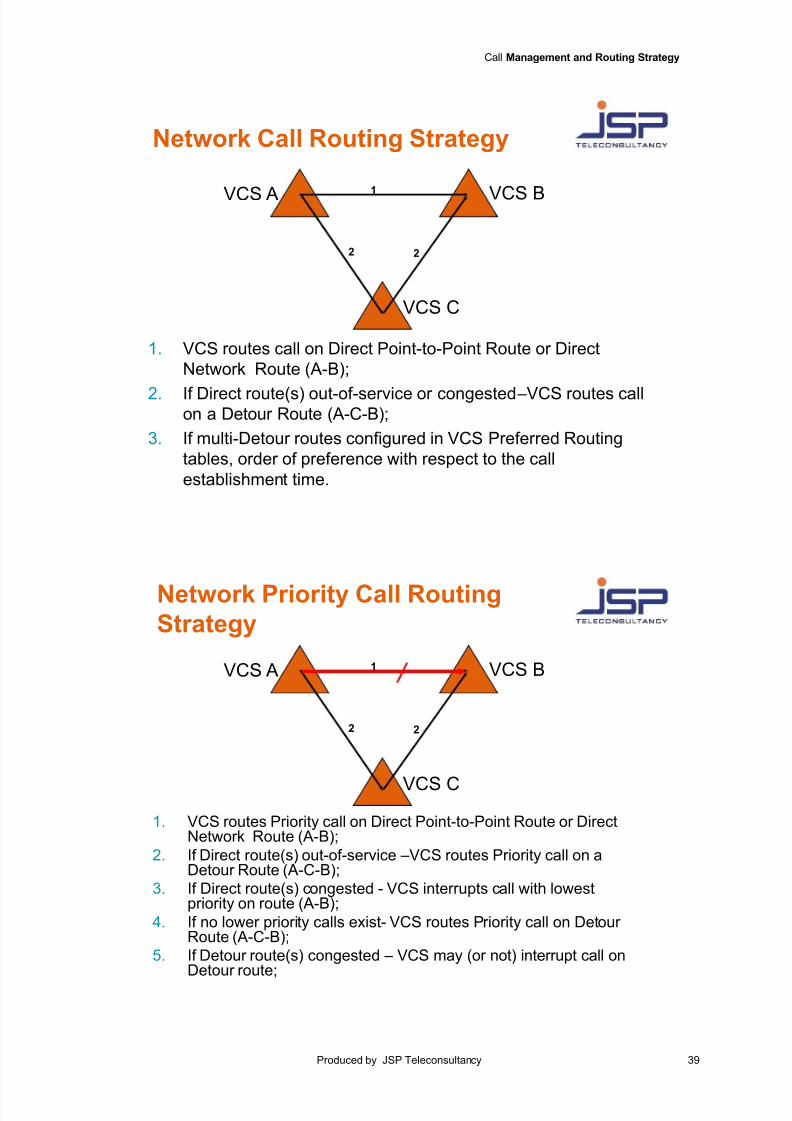
ATS MFC-R2 Routing
Direct Routing
In order to keep within the time limits for establishing instantaneous connections that were agreed by the 6thICAO European Mediterranean Meeting, it was recommended that provision be made for direct routing betweenadjacent centres. The trunk provided shall have sufficient capacity to ensure that only in exceptional
circumstances will traffic have to be routed via detour routes.
Detour Routing
If a direct trunk between two ATS units is congested or is completely or partly out of service, detour routing shall beused to meet the communication requirements. With a stored-program-control Switch the number of possible detourroutes is limited only by the number of different trunks available. In the event of detour routing being necessary, onlyone transit Switch is recommended to be added in order to make the through connection when using the ATSMFC-R2 signalling protocol. This means that only two circuits (segments) will be switched in tandem.
If the detour routing is not properly managed, there may be a risk of long delays and of creating an excessiveload on the network, including some "merry-go-round" switching (endless loop). For this reason a second (but nota third) circuit shall be switched in tandem. This can best be done if the incoming call to a Switch alreadycontains a clear indication as to whether it is a direct call or whether it has been subject to detour switching. Forthis purpose the originating Switch shall give the indication required.
It is recommended that this indication should be obtained by increasing the priority level associated with the callby five. For example, if a call with priority level two is sent via an alternate route the priority level should beincreased to seven. Remember that the Priority level associated with a call is defined by 7th digit in the 13-digitnumerical sequence.
Time Out Setting
Since calls within the ATS environment have a certain degree of urgency, yet the network has only a limitedcapacity, each call shall be carefully monitored and a maximum overall time shall be set for the execution of thesignalling procedure. As already mentioned, a direct route call shall be connected within 2 s. If a call is switchedvia a detour route the signalling sequence shall not exceed 5 s, depending mainly on the type of transit Switchinvolved.
It is recommended that the maximum overall time-out for the signalling procedure should be set at 8 s.
ATS-R2 Call routing & Interrupt strategyATS R2 Call Priority level implementation
The 7th digit in the 13-digit address sequence shall be used to define the call priority level of the ATS R2 call. This
can have the value 1, 2, 3 or 4 on a Direct Point-to-Point route.
An originating or transit VCS should increase the value of the 7th digit in the 13-digit sequence by 5 when it routes
the call over a Detour route with respect to the Direct Point-to-Point route.
Call Priority level ranges for Direct/Detour routes
ATS R2 Call Priority Level Call Routing
1-4 Via a Direct Point-to-Point route
6-9 Via a Detour route
The priority level of an ATS R2 call is a means of attaching an indicator to the call to show its level of importance.It is intended for use when it is necessary to make an urgent call concerning the safety of aircraft (i.e. anemergency situation) and to enable the interruption of less urgent calls in progress at the time if the inter-VCS linkis congested.
A Priority Level 1 call (highest) is able to interrupt calls of lower Priority level.
Some ANSP’s also allow a Priority Level 2 call to interrupt those of levels 3 and 4.
Normally Priority Level 3 and 4 calls can not interrupt other calls.
If an ANSP allows interruption of calls on the first and second link of a detour route, then a Priority Level 1 call isnot increased by 5 for a detour route.
For further information about “Priority Calls” and “Priority Call Management and Routing Strategy” within the “ATS
Ground Voice Network”, refer to Eurocontrol document entitled “ATS Ground Voice Network Implementation andPlanning Guidelines”.
7/18/2019 ATS MFC-R2 Analogue Signalling
http://slidepdf.com/reader/full/ats-mfc-r2-analogue-signalling 43/55
Call Management and Routing Strategy
Produced by JSP Teleconsultancy 41
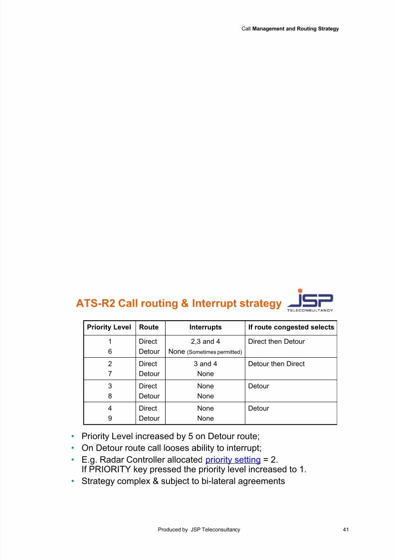
ATS-R2 Call routing & Interrupt strategy
Priority Level Route Interrupts If route congested selects
1
6
Direct
Detour
2,3 and 4
None (Sometimes permitted)
Direct then Detour
2
7
Direct
Detour
3 and 4
None
Detour then Direct
3
8
Direct
Detour
None
None
Detour
4
9
Direct
Detour
None
None
Detour
• Priority Level increased by 5 on Detour route;
• On Detour route call looses ability to interrupt;
• E.g. Radar Controller allocated priority setting = 2.If PRIORITY key pressed the priority level increased to 1.
• Strategy complex & subject to bi-lateral agreements
7/18/2019 ATS MFC-R2 Analogue Signalling
http://slidepdf.com/reader/full/ats-mfc-r2-analogue-signalling 44/55
42 © Copyright 2014 JSP-Teleconsultancy
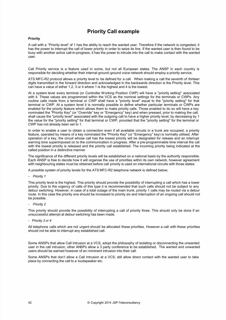
Priority Call example
Priority
A call with a “Priority level” of 1 has the ability to reach the wanted user. Therefore if the network is congested, ithas the power to interrupt the call of lower priority in order to seize its line. If the wanted user is then found to bebusy with another active call-in-progress, it has the power to intrude into the call to make contact with the wanted
user.
Call Priority service is a feature used in some, but not all European states. The ANSP in each country isresponsible for deciding whether their internal ground-ground voice network should employ a priority service.
ATS MFC-R2 protocol allows a priority level to be defined for a call. When making a call the seventh of thirteendigits transmitted in the forward direction and acknowledged in the backwards direction is the Priority level. Thiscan have a value of either 1,2, 3 or 4 where 1 is the highest and 4 is the lowest.
At a system level every terminal (or Controller Working Position CWP) will have a "priority setting" associatedwith it. These values are programmed within the VCS as the nominal settings for the terminals or CWPs. Anyroutine calls made from a terminal or CWP shall have a "priority level" equal to the "priority setting" for thatterminal or CWP. At a system level it is normally possible to define whether particular terminals or CWPs areenabled for the priority feature which allows them to make priority calls. Those enabled to do so will have a key
nominated the "Priority Key" (or “Override” key or “Emergency” key) and when pressed, prior to making the call,shall cause the "priority level" associated with the outgoing call to have a higher priority level, by decreasing by 1the value for the "priority setting" for that terminal or CWP, provided that the "priority setting" for the terminal orCWP has not already been set to 1.
In order to enable a user to obtain a connection even if all available circuits in a trunk are occupied, a priorityfeature, operated by means of a key nominated the "Priority Key" (or “Emergency” key) is normally utilised. Afteroperation of a key, the circuit whose call has the lowest priority will be designated for release and an interruptwarning tone superimposed on to the communication in progress. After a pre-programmable time interval the callwith the lowest priority is released and the priority call established. The incoming priority being indicated at thecalled position in a distinctive manner.
The significance of the different priority levels will be established on a national basis by the authority responsible.Each ANSP is free to decide how it will organise the use of priorities within its own network, however agreementwith neighbouring states must be obtained before call priority is used on international circuits with those states.
A possible system of priority levels for the ATS MFC-R2 telephone network is defined below;
- Priority 1
This priority level is the highest. This priority should provide the possibility of interrupting a call which has a lowerpriority. Due to the urgency of calls of this type it is recommended that such calls should not be subject to anydetour switching. However, in case of a total outage of the main trunk, priority 1 calls may be routed via a detourroute. In this case the priority one should be increased to priority six and interruption of an ongoing call should notbe possible.
- Priority 2
This priority should provide the possibility of interrupting a call of priority three. This should only be done if anunsuccessful attempt at detour switching has been made.
- Priority 3 or 4
All telephone calls which are not urgent should be allocated these priorities. However a call with these prioritiesshould not be able to interrupt any established call.
Some ANSPs that allow Call Intrusion at a VCS, adopt the philosophy of isolating or disconnecting the unwanteduser in the call intrusion, other ANSPs allow a 3 party conference to be established. The wanted and unwantedusers should be warned however of an imminent intrusion into their call.
Some ANSPs that don’t allow a Call Intrusion at a VCS, s till allow direct contact with the wanted user to takeplace by connecting the call to a loudspeaker etc.
7/18/2019 ATS MFC-R2 Analogue Signalling
http://slidepdf.com/reader/full/ats-mfc-r2-analogue-signalling 45/55
Call Management and Routing Strategy
Produced by JSP Teleconsultancy 43
example
• Call Priority Interrupt - Allowed by ANSP
• Call Intrusion – Allowed by ANSP
Routine call (Priority Level 3)
Routine call (Priority Level 2)
Routine call (Priority Level 2)
Some ANSP’s isolate
unwanted user during
Call intrusion, others
allow 3-party conference
Emergency !
Priority Call
Priority Level 1 call
Hears interrupt
warning tone<15s
(Rec. 5s)
Hears interrupt
warning tone<15s
(Rec. 5s)
Hears intrusion
warning tone of 1s
Wanted
user
Unwanted
user
7/18/2019 ATS MFC-R2 Analogue Signalling
http://slidepdf.com/reader/full/ats-mfc-r2-analogue-signalling 46/55
44 © Copyright 2014 JSP-Teleconsultancy
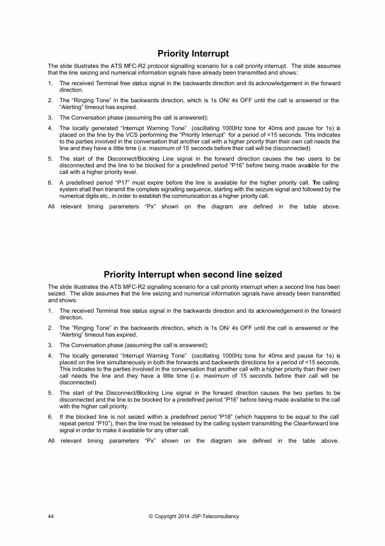
Priority Interrupt
The slide illustrates the ATS MFC-R2 protocol signalling scenario for a call priority interrupt. The slide assumesthat the line seizing and numerical information signals have already been transmitted and shows:
1. The received Terminal free status signal in the backwards direction and its acknowledgement in the forwarddirection.
2. The “Ringing Tone” in the backwards direction, wh ich is 1s ON/ 4s OFF until the call is answered or the“Alerting” timeout has expired.
3. The Conversation phase (assuming the call is answered);
4. The locally generated “Interrupt Warning Tone” (oscillating 1000Hz tone for 40ms and pause for 1s) isplaced on the line by the VCS performing the “Priority Interrupt” for a period of <15 seconds. This indicatesto the parties involved in the conversation that another call with a higher priority than their own call needs theline and they have a little time (i.e. maximum of 15 seconds before their call will be disconnected)
5. The start of the Disconnect/Blocking Line signal in the forward direction causes the two users to bedisconnected and the line to be blocked for a predefined period “P16” before being made available for thecall with a higher priority level.
6. A predefined period “P17” must expire before the line is available for the higher priority call. The calling
system shall then transmit the complete signalling sequence, starting with the seizure signal and followed by thenumerical digits etc., in order to establish the communication as a higher priority call.
All relevant timing parameters “Px” shown on the diagram are defined in the table above.
Priority Interrupt when second line seized
The slide illustrates the ATS MFC-R2 signalling scenario for a call priority interrupt when a second line has beenseized. The slide assumes that the line seizing and numerical information signals have already been transmittedand shows:
1. The received Terminal free status signal in the backwards direction and its acknowledgement in the forwarddirection.
2. The “Ringing Tone” in the backwards direction, which is 1s ON/ 4s OFF until the call is answered or the“Alerting” timeout has expired.
3. The Conversation phase (assuming the call is answered);
4. The locally generated “Interrupt Warning Tone” (oscillating 1000Hz tone for 40ms and pause for 1s) isplaced on the line simultaneously in both the forwards and backwards directions for a period of <15 seconds.This indicates to the parties involved in the conversation that another call with a higher priority than their owncall needs the line and they have a little time (i.e. maximum of 15 seconds before their call will be
disconnected)
5. The start of the Disconnect/Blocking Line signal in the forward direction causes the two parties to bedisconnected and the line to be blocked for a predefined period “P16” before being made available to the callwith the higher call priority.
6. If the blocked line is not seized within a predefined period “P18” (which happens to be equal to the callrepeat period “P10”), then the line must be released by the calling system transmitting the Clear -forward linesignal in order to make it available for any other call.
All relevant timing parameters “Px” shown on the diagram are defined in the table above.
7/18/2019 ATS MFC-R2 Analogue Signalling
http://slidepdf.com/reader/full/ats-mfc-r2-analogue-signalling 47/55
Call Management and Routing Strategy
Produced by JSP Teleconsultancy 45
Priority Interrupt
BLOCKING D1
AD1
SEIZURE
CONVERSATION
Int. Warn. Tone. Loc. Gen.
P13 <15s
SIDE A (initiated call) : Third Party interrupts line from A side
SIDE B
2280 HZ
A B3
1 2
Term.Free
D2
AD2
backward signals
forward signals
Ack.
Term.
Free
RingingTone
P12P11
P14 P14P15P16 P17
Example of Call Priority Interrupt
4
Priority Interrupt when second line seized
BO231_1179
DISCONNECT/
BLOCKING
CLEAR
FORWARD
CONVERSATION
Int. Warn. Tone. Loc. Gen.
P13 <15s
2280 HZ
Term.
Free
backward signals
forward signals
Ack.
Term.
Free
RingingTone
P12P11
P14 P14P15P16 P18 P9
If higher priority call already
seized a different line,
the blocked line is released.If higher priority call already
seized a different line,
call interrupt is abandoned
7/18/2019 ATS MFC-R2 Analogue Signalling
http://slidepdf.com/reader/full/ats-mfc-r2-analogue-signalling 48/55
46 © Copyright 2014 JSP-Teleconsultancy
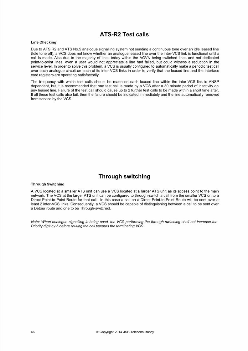
ATS-R2 Test calls
Line Checking
Due to ATS R2 and ATS No.5 analogue signalling system not sending a continuous tone over an idle leased line(Idle tone off), a VCS does not know whether an analogue leased line over the inter-VCS link is functional until acall is made. Also due to the majority of lines today within the AGVN being switched lines and not dedicated
point-to-point lines, even a user would not appreciate a line had failed, but could witness a reduction in theservice level. In order to solve this problem, a VCS is usually configured to automatically make a periodic test callover each analogue circuit on each of its inter-VCS links in order to verify that the leased line and the interfacecard registers are operating satisfactorily.
The frequency with which test calls should be made on each leased line within the inter-VCS link is ANSPdependent, but it is recommended that one test call is made by a VCS after a 30 minute period of inactivity onany leased line. Failure of the test call should cause up to 2 further test calls to be made within a short time after.If all these test calls also fail, then the failure should be indicated immediately and the line automatically removedfrom service by the VCS.
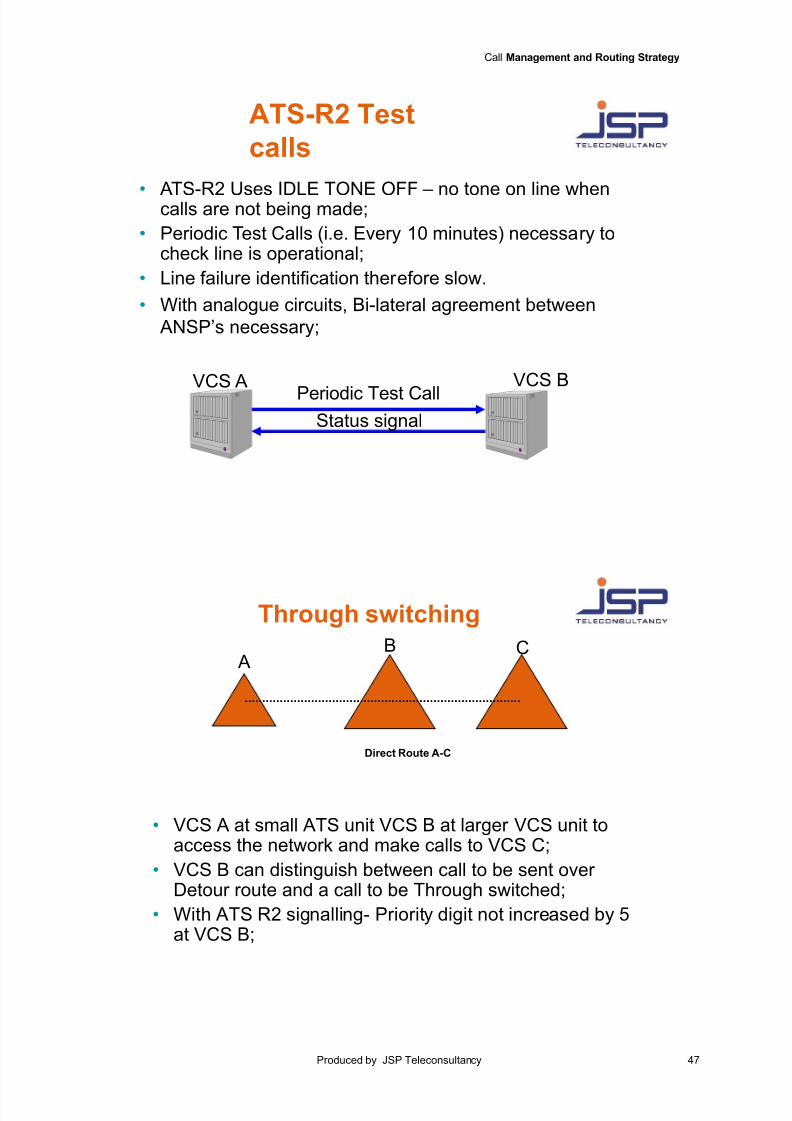
Through switching
Through Switching
A VCS located at a smaller ATS unit can use a VCS located at a larger ATS unit as its access point to the mainnetwork. The VCS at the larger ATS unit can be configured to through-switch a call from the smaller VCS on to aDirect Point-to-Point Route for that call. In this case a call on a Direct Point-to-Point Route will be sent over atleast 2 inter-VCS links. Consequently, a VCS should be capable of distinguishing between a call to be sent overa Detour route and one to be Through-switched.
Note: When analogue signalling is being used, the VCS performing the through switching shall not increase thePriority digit by 5 before routing the call towards the terminating VCS.
7/18/2019 ATS MFC-R2 Analogue Signalling
http://slidepdf.com/reader/full/ats-mfc-r2-analogue-signalling 49/55
Call Management and Routing Strategy
Produced by JSP Teleconsultancy 47
ATS-R2 Test
calls
• ATS-R2 Uses IDLE TONE OFF – no tone on line whencalls are not being made;
• Periodic Test Calls (i.e. Every 10 minutes) necessary tocheck line is operational;
• Line failure identification therefore slow.
• With analogue circuits, Bi-lateral agreement between
ANSP’s necessary;
VCS BPeriodic Test Call
VCS A
Status signal
Direct Route A-C
AB C
Through switching
• VCS A at small ATS unit VCS B at larger VCS unit toaccess the network and make calls to VCS C;
• VCS B can distinguish between call to be sent overDetour route and a call to be Through switched;
• With ATS R2 signalling- Priority digit not increased by 5at VCS B;
7/18/2019 ATS MFC-R2 Analogue Signalling
http://slidepdf.com/reader/full/ats-mfc-r2-analogue-signalling 50/55
48 © Copyright 2014 JSP-Teleconsultancy
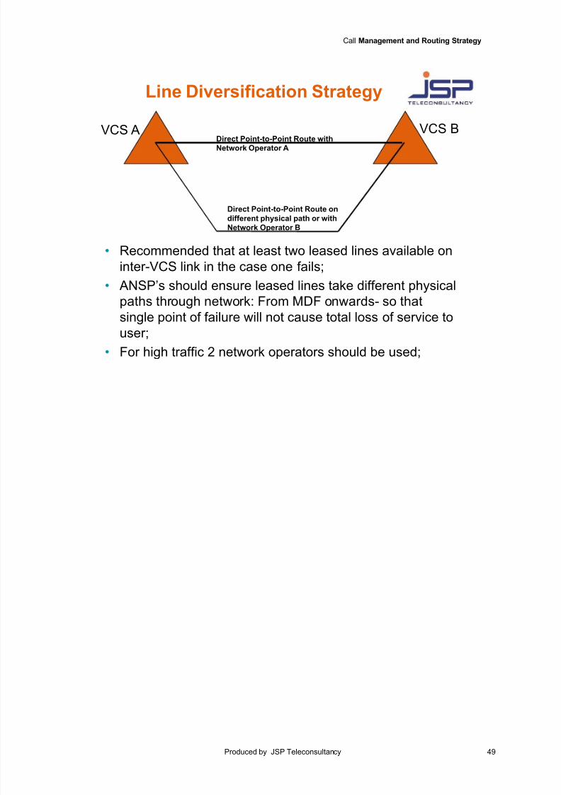
Line Diversification Strategy
Line diversification for Direct Routes
It is recommended that even for a minimum amount of traffic at least two leased lines should be available on aninter-VCS link in the case that one fails. An ANSP should ensure a Network Operator has implemented linediversification (i.e. that leased lines take different physical paths through the network), in order that a single point
of failure doesn’t cause a total loss of service to the user;
For an inter-VCS link comprising of many lines transporting a high quantity of traffic, it is recommended that asecond Direct Point-to-Point Route or Direct Network Route is active between the originating and terminatingVCS. This second route should use the leased lines from a different Network Operator to that used for the firstdirect route. It is assumed that lines leased from different Network Operators would take different physical pathsfrom the Main Distribution Frame onwards.
This will reduce a single point of failure in the ATS network for multiple lines between ATS units. Ideally the VCSshould be configured to share traffic between these direct routes. A second direct route could even be used as abackup to the first direct route.
7/18/2019 ATS MFC-R2 Analogue Signalling
http://slidepdf.com/reader/full/ats-mfc-r2-analogue-signalling 51/55
Call Management and Routing Strategy
Produced by JSP Teleconsultancy 49
VCS A
Direct Point-to-Point Route on
different physical path or with
Network Operator B
Direct Point-to-Point Route withNetwork Operator A
VCS B
Line Diversification Strategy
• Recommended that at least two leased lines available on
inter-VCS link in the case one fails;
• ANSP’s should ensure leased lines take different physical
paths through network: From MDF onwards- so that
single point of failure will not cause total loss of service to
user;
• For high traffic 2 network operators should be used;
7/18/2019 ATS MFC-R2 Analogue Signalling
http://slidepdf.com/reader/full/ats-mfc-r2-analogue-signalling 52/55
50 © Copyright 2014 JSP-Teleconsultancy
Analogue ATS MFC-R2 Analogue
interface
7/18/2019 ATS MFC-R2 Analogue Signalling
http://slidepdf.com/reader/full/ats-mfc-r2-analogue-signalling 53/55
Call Management and Routing Strategy
Produced by JSP Teleconsultancy 51
Glossary
AGVN ATS Ground Voice Network ANSP Air Navigation Service Provider ATC Air Traffic Control ATS Air Traffic ServicesCAS Channel Associated SignallingCWP Controller Working PositionDA Direct AccessICAO International Civil Aviation OrganisationITU-T International Telecommunications Union - TelecommunicationLD Loop DisconnectMFC Multi Frequency CompelledMFC-R2 Multi-Frequency Compelled R2PABX Private Automatic Branch ExchangePCM Pulse Code ModulationQSIG Signalling at the Q reference pointTO Operation TimeTPB Propagation backward delay
TPF Propagation forward delayTR Release timeTS Starting and Stopping timeVCS Voice Communication System

7/18/2019 ATS MFC-R2 Analogue Signalling
http://slidepdf.com/reader/full/ats-mfc-r2-analogue-signalling 54/55
52 © Copyright 2014 JSP-Teleconsultancy
Analogue ATS MFC-R2 Analogue
interface

7/18/2019 ATS MFC-R2 Analogue Signalling
http://slidepdf.com/reader/full/ats-mfc-r2-analogue-signalling 55/55
Call Management and Routing Strategy


![Reference Guide MFC-J6947DW MFC-J6945DW MFC-J6545DW · MFC-J6545DW MFC-J6945DW MFC-J6947DW ... [Message from Brother] and [Firmware Auto Check] are set to [On]. (Internet connection](https://img.pdfslide.us/doc/110x75/5fe53fa6fe9ed37e6d21c94e/reference-guide-mfc-j6947dw-mfc-j6945dw-mfc-j6545dw-mfc-j6545dw-mfc-j6945dw-mfc-j6947dw.jpg)