Embed Size (px)
Citation preview
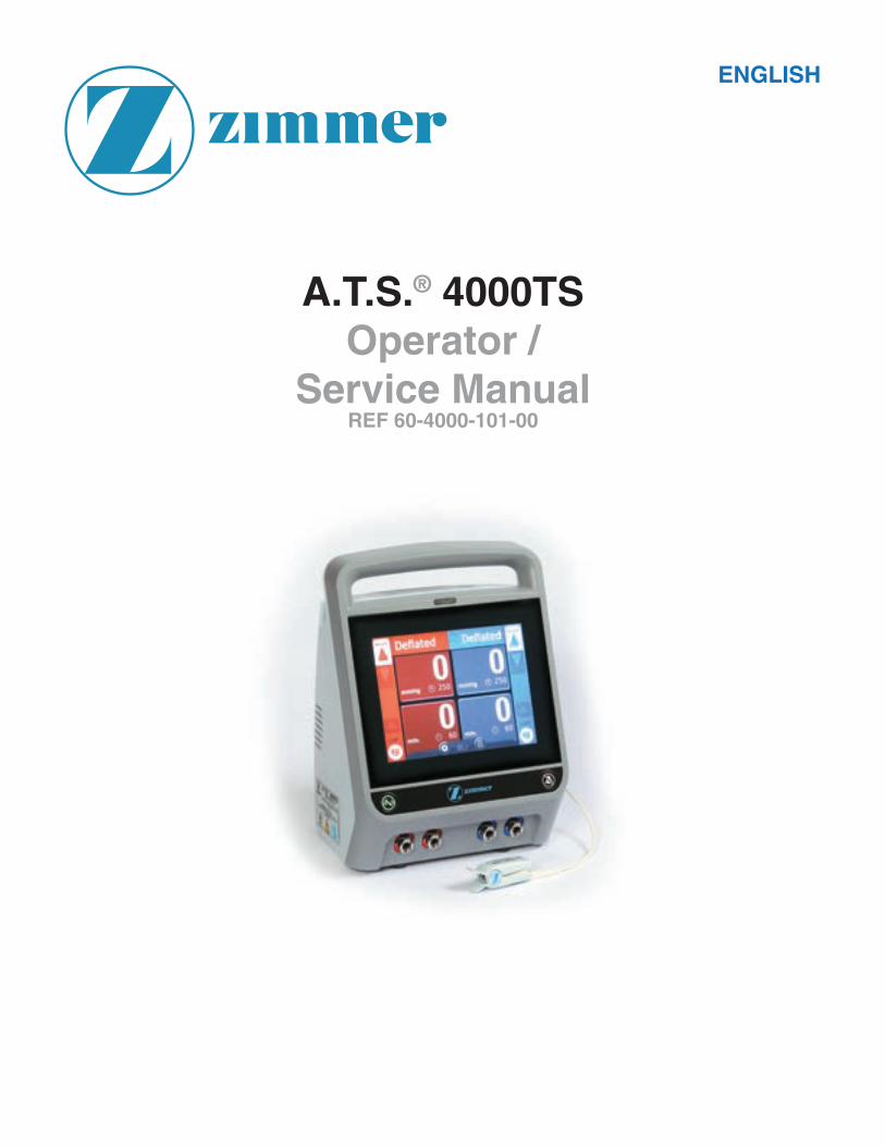
A.T.S.® 4000TSOperator /
Service ManualREF 60-4000-101-00
ENGLISH
Page 1
WARRANTY
LIMITED ONE YEAR WARRANTY INSIDE U.S.A.
SCOPE OF LIMITED WARRANTY
Zimmer, Inc. warrants the Product (A.T.S. 4000TS Tourniquet System) for one year from date of purchase.
During the warranty period, Zimmer will repair or replace, at its option, any product which is defective in
materials or workmanship or which fails to meet the published specifi cation for that model. This Limited
Warranty is made only to the original purchaser of the product and is non-transferable. The remedies
described in this Limited Warranty are the exclusive remedies for breach of warranty. THIS WARRANTY
SHALL NOT APPLY TO ANY PRODUCT WHICH HAS BEEN ALTERED OR MODIFIED IN ANY WAY, OR
WHICH HAS BEEN SUBJECTED TO MISUSE OR ABUSE.
DISCLAIMER OF IMPLIED WARRANTIES
The forgoing of Express Limited Warranty is given in lieu of any and all other express or implied
warranties. ZIMMER MAKES NO OTHER WARRANTIES INCLUDING THE IMPLIED WARRANTIES OF
MERCHANTABILITY OR FITNESS FOR A PARTICULAR PURPOSE.
LIMITATION OF REMEDIES
In no case shall Zimmer, Inc. be liable for any special, incidental, or consequential damages whether based
on breach of warranty or other legal theory whether or not such damages are foreseeable. Some states do
not allow limitations on warranties or on remedies for breach in certain transactions. In such states, the limits
in this paragraph and the preceding paragraph do not apply.
WARRANTY CLAIMS
In the event of a warranty claim within the warranty period please take the following steps:
• Notify Customer Service Department, Zimmer Surgical, at 1-800-348-2759 or contact your local Zimmer representative. Please provide details about the nature of the problem and include the product serial number. Upon receipt of this information, Zimmer will provide a date for service or a return shipping authorization.
• Upon receipt of the shipping authorization, forward the equipment, freight prepaid, to the location specifi ed in the shipping authorization.
Your compliance with these steps will help assure that you receive prompt warranty service for your product.
WARRANTY OUTSIDE U.S.A.
SCOPE OF WARRANTY
Please contact your local Zimmer Representative for warranty information.
Unit Serial Number _____________________________________________________________
Page 2
CONTENTS
TABLE OF CONTENTS
1 GENERAL INFORMATION ............................................................... 4
INTENDED USE ...................................................................................................................4
CONTRAINDICATIONS .......................................................................................................4
PRECAUTIONS IN USE .......................................................................................................5
ADVERSE EFFECTS ...........................................................................................................6
SPECIFICATIONS AND PERFORMANCE CHARACTERISTICS .......................................6
ES 60601-1 CLASSIFICATION ............................................................................................8
EMISSIONS/IMMUNITY .......................................................................................................8
2 INSTALLATION AND OPERATING INSTRUCTIONS ........................ 9
INITIAL VISUAL INSPECTION ............................................................................................9
FEATURES AND OPERATING PRINCIPLES .....................................................................9
BUTTONS AND ICONS ............................................................................................................................. 9
TOUCH SCREEN GUI ........................................................................................................14
INITIAL SETUP ..................................................................................................................15
TESTS AND CHECKS .......................................................................................................15
AUTOMATIC DIAGNOSTIC AND CALIBRATION CHECK .....................................................................15
MANUAL TESTS AND CHECKS ............................................................................................................16
SYSTEM FUNCTIONS .......................................................................................................22
SETTINGS ...............................................................................................................................................22
DOCUMENTATION ..................................................................................................................................27
OPERATION .......................................................................................................................27
SURGEON DECISIONS ..........................................................................................................................28
PATIENT PREPARATION ........................................................................................................................28
LIMB OCCLUSION PRESSURE (LOP) ..................................................................................................29
LOP MEASUREMENT .............................................................................................................................31
CUFF OPERATION .................................................................................................................................35
ALARM CONDITIONS .......................................................................................................40
PRESSURE ALARMS .............................................................................................................................41
ADVANCED LEAK DETECTION .............................................................................................................41
ALARM/WARNING COLORS AND AUDIBLE TONES ...........................................................................42
ALARM CONDITION AND ERROR CODE TABLES ..............................................................................42
ELECTROMAGNETIC COMPATIBILITY (EMC) GUIDANCE TABLES .............................48
Page 3
CONTENTS
3 MAINTENANCE ............................................................................. 52
GENERAL MAINTENANCE INFORMATION.....................................................................52
LOP SENSOR CLEANING AND DISINFECTING .............................................................52
PERIODIC MAINTENANCE ...............................................................................................52
SERVICING ........................................................................................................................53
SERVICE MENU ACCESS ......................................................................................................................53
CALIBRATION .........................................................................................................................................53
ATS LEAK TESTING ...............................................................................................................................59
UNIT INFORMATION ACCESS ...............................................................................................................60
BURN MODE ...........................................................................................................................................60
TOUCH TEST ...........................................................................................................................................61
PROTECTIVE EARTH RESISTANCE TESTING .....................................................................................62
EARTH (EQUIPMENT) LEAKAGE CURRENT TESTING .......................................................................62
INSULATION RESISTANCE TESTING ...................................................................................................62
BACKUP BATTERY SERVICE ...........................................................................................62
BATTERY-HANDLING RECOMMENDATIONS ......................................................................................63
FUSE AND FUSE DRAWER REPLACEMENT ..................................................................64
UNSCHEDULED MAINTENANCE .....................................................................................64
TROUBLE SHOOTING GUIDE ..........................................................................................65
TROUBLESHOOTING .............................................................................................................................65
REPLACEMENT PARTS ....................................................................................................66
PARTS LIST .............................................................................................................................................66
ORDER INFORMATION ..........................................................................................................................68
CONTACT INFORMATION .................................................................................................68
ENVIRONMENTAL CONDITIONS .....................................................................................69
WARNINGS, CAUTIONS & SYMBOLOGY........................................................................69
TEST AND EVALUATION REPORT (BLANK) ........................................................................................73
Page 4
GENERAL INFORMATION
GENERAL INFORMATION
APPLICATION SPECIFICATION
The application specifi cation for the A.T.S. 4000TS including characteristics related to the use of the device, intended use, intended patient population, intended part of the body, intended user profi le, intended conditions of use and operating principles is contained in this manual.
INTENDED USE
The A.T.S. 4000TS Tourniquet System is intended to be used by qualifi ed medical professionals to temporarily occlude blood fl ow in a patient’s extremities during surgical procedures on those extremities. Tourniquets have been found useful in producing a bloodless operation fi eld in surgical procedures involving the extremities including:
• Reduction of certain fractures. • Kirschner wire removal.
• Subcutaneous fasciotomy. • Nerve injuries.
• Bone grafts. • Total wrist joint replacement.
• Knee joint replacements. • Amputations.
• Tumor and cyst excisions. • Tendon repair.
• Replacement of joints in the fi ngers. • Replantations.
WARNING: Do not use Tourniquet cuffs to control the distal fl ow of CO2 or any other gases used as a
distention media. Tourniquet cuffs have not been evaluated for safety or effectiveness in controlling gas fl ow beyond the surgical site during arthroscopic insuffl ation procedures. Possible effects of using a Tourniquet cuff in this manner include serious subcutaneous emphysema proximal to the cuff.
CONTRAINDICATIONS
The medical literature lists the following as possible contraindications:
• Open fractures of the leg.
• Post-traumatic lengthy hand reconstruction.
• Severe crushing injuries.
• Elbow surgery (where there is excess swelling).
• Severe Hypertension.
• Diabetes mellitus.
• Skin grafts in which all bleeding points must be readily distinguished.
• Compromised vascular circulation, e.g., peripheral artery disease.
• The presence of sickle cell disease is a relative contraindication (See PRECAUTIONS IN USE).
CAUTION:
• In every case, the fi nal decision whether to use a Tourniquet rests with the attending physician.
• A Tourniquet should also be avoided in patients who are undergoing secondary or delayed procedures after immobilization.
• Certain physiologic or anatomical conditions, including small fi ngers and toes of infants and children, may prevent the A.T.S. 4000TS from making a determination of LOP, in which case the instrument will display an appropriate message and will terminate the attempt to measure LOP. In that event, the physician’s judgment should be used to set Tourniquet pressure in the absence of the LOP feature.
Page 5
GENERAL INFORMATION
PRECAUTIONS IN USE
• Not for use in an oxygen rich environment with an oxygen concentration greater than 25% for ambient pressures up to 110 kPa or the partial pressure of oxygen is greater than 27.5 kPa at ambient pressures exceeding 110 kPa.
• Normal operation has the A.T.S. 4000TS running on ~ AC Power Mains via its power cord. The backup battery is intended for emergency power or transport.
• The Tourniquet system must be kept well calibrated and in operable condition. Accessories should be checked regularly for leaks and other defects.
• The Tourniquet cuff must never be punctured; therefore towel clips used near the system must be handled with special care. Cuffs with inner rubber bladders must be completely enclosed by the outer envelope to preclude ballooning and possible rupture of the bladder. Cleaning and assembly instructions of the cuff manufacturer should be followed carefully.
• Do not use an elastic bandage for exsanguination in cases where this will cause bacteria, exotoxins, or malignant cells to spread to the general circulation, or where it could dislodge thromboemboli that may have formed in the vessels.
• The Tourniquet cuff must be applied in the proper location on the limb, for a “safe” period of time, and within an appropriate pressure range. Never apply a Tourniquet over the area of the peroneal nerve or over the knee or ankle. Do not readjust an already infl ated cuff by rotating it because this produces shearing forces which may damage the underlying tissue.
• Prolonged ischemia may lead to temporary or permanent damage to tissues, blood vessels, and nerves. Tourniquet paralysis may result from excessive pressure. Insuffi cient pressure may result in passive congestion of the limb with possible irreversible functional loss. Prolonged Tourniquet time can also produce changes in the coagulability of the blood with increased clotting time.
• Infl ation should be done rapidly to occlude arteries and veins as near simultaneously as possible.
• Careful and complete exsanguination reportedly prolongs pain free Tourniquet time and improves the quality of Intravenous Regional Anesthesia (IVRA), also known as Bier Block anesthesia. In the presence of infection and painful fractures, after the patient has been in a cast, and in amputations because of malignant tumors, exsanguination before Tourniquet application may be done without the use of an elastic bandage by elevating the limb for 3 to 5 minutes.
• In case of failure, the Tourniquet cuff must be fully defl ated and the limb exsanguinated again before reinfl ation. Reinfl ation over blood-fi lled vasculature may lead to intravascular thrombosis.
• Tourniquet users must be familiar with the infl ation-defl ation sequence when using a dual-cuff Tourniquet or two Tourniquet cuffs together for IVRA (Bier Block anesthesia), so that the wrong Tourniquet will not be released accidentally.
• Test for hemoglobin type and level before using a Tourniquet on patients with sickle-cell anemia. When the Tourniquet is used for these patients, the limb should be carefully exsanguinated and the PO
2 and pH should be
closely monitored.
• Select the proper cuff size to allow for an overlap of about 3 to 6 in. (7.6–15 cm). Too much overlap may cause cuff rolling and telescoping, and may lead to undesired pressure distribution on the limb. The skin under the Tourniquet cuff must be protected from mechanical injury by smooth, wrinkle-free application of the cuff. If the Tourniquet cuff is applied over any material that may shed loose fi bers (such as Webril) the fi bers may become embedded in the contact closures and reduce their effectiveness. As an under padding, a section of stockinette may be used. The defl ated cuff and any underlying bandage or protective sleeve should be completely removed as soon as Tourniquet pressure is released. After the cuff has been fully defl ated and removed from the patient, the unit can be set to STANDBY. Even the slightest impedance of venous return may lead to congestion and pooling of blood in the operative fi eld.
• If skin preparations are used preoperatively, they should not be allowed to fl ow and collect under the cuff where they may cause chemical burns.
Page 6
GENERAL INFORMATION
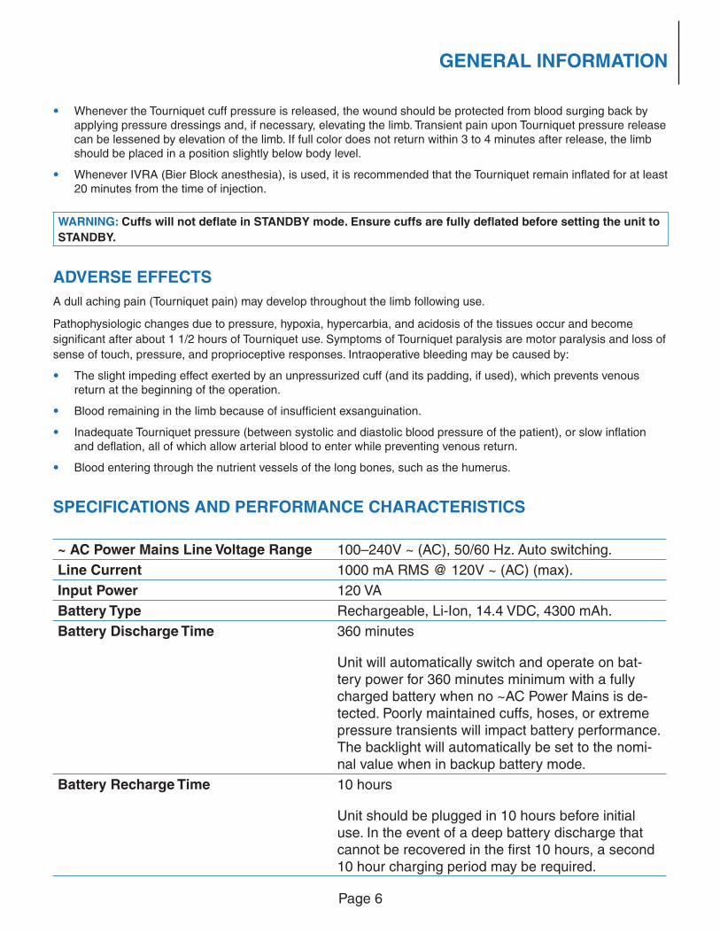
• Whenever the Tourniquet cuff pressure is released, the wound should be protected from blood surging back by applying pressure dressings and, if necessary, elevating the limb. Transient pain upon Tourniquet pressure release can be lessened by elevation of the limb. If full color does not return within 3 to 4 minutes after release, the limb should be placed in a position slightly below body level.
• Whenever IVRA (Bier Block anesthesia), is used, it is recommended that the Tourniquet remain infl ated for at least 20 minutes from the time of injection.
WARNING: Cuffs will not defl ate in STANDBY mode. Ensure cuffs are fully defl ated before setting the unit to
STANDBY.
ADVERSE EFFECTS
A dull aching pain (Tourniquet pain) may develop throughout the limb following use.
Pathophysiologic changes due to pressure, hypoxia, hypercarbia, and acidosis of the tissues occur and become
signifi cant after about 1 1/2 hours of Tourniquet use. Symptoms of Tourniquet paralysis are motor paralysis and loss of
sense of touch, pressure, and proprioceptive responses. Intraoperative bleeding may be caused by:
• The slight impeding effect exerted by an unpressurized cuff (and its padding, if used), which prevents venous return at the beginning of the operation.
• Blood remaining in the limb because of insuffi cient exsanguination.
• Inadequate Tourniquet pressure (between systolic and diastolic blood pressure of the patient), or slow infl ation and defl ation, all of which allow arterial blood to enter while preventing venous return.
• Blood entering through the nutrient vessels of the long bones, such as the humerus.
SPECIFICATIONS AND PERFORMANCE CHARACTERISTICS
~ AC Power Mains Line Voltage Range 100–240V ~ (AC), 50/60 Hz. Auto switching.
Line Current 1000 mA RMS @ 120V ~ (AC) (max).
Input Power 120 VA
Battery Type Rechargeable, Li-Ion, 14.4 VDC, 4300 mAh.
Battery Discharge Time 360 minutes
Unit will automatically switch and operate on bat-
tery power for 360 minutes minimum with a fully charged battery when no ~AC Power Mains is de-tected. Poorly maintained cuffs, hoses, or extreme
pressure transients will impact battery performance.
The backlight will automatically be set to the nomi-nal value when in backup battery mode.
Battery Recharge Time 10 hours
Unit should be plugged in 10 hours before initial use. In the event of a deep battery discharge that
cannot be recovered in the fi rst 10 hours, a second 10 hour charging period may be required.
Page 7
GENERAL INFORMATION
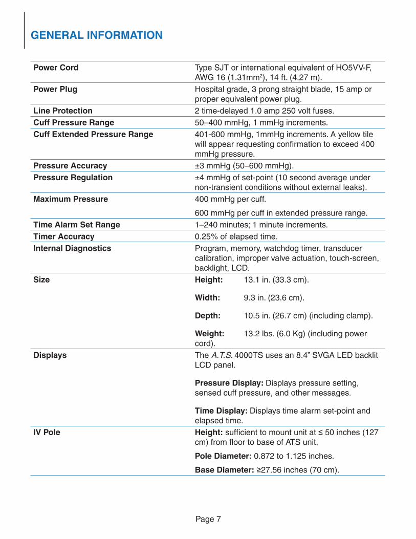
Power Cord Type SJT or international equivalent of HO5VV-F,
AWG 16 (1.31mm2), 14 ft. (4.27 m).
Power Plug Hospital grade, 3 prong straight blade, 15 amp or
proper equivalent power plug.
Line Protection 2 time-delayed 1.0 amp 250 volt fuses.
Cuff Pressure Range 50–400 mmHg, 1 mmHg increments.
Cuff Extended Pressure Range 401-600 mmHg, 1mmHg increments. A yellow tile
will appear requesting confi rmation to exceed 400
mmHg pressure.
Pressure Accuracy ±3 mmHg (50–600 mmHg).
Pressure Regulation ±4 mmHg of set-point (10 second average under
non-transient conditions without external leaks).
Maximum Pressure 400 mmHg per cuff.
600 mmHg per cuff in extended pressure range.
Time Alarm Set Range 1–240 minutes; 1 minute increments.
Timer Accuracy 0.25% of elapsed time.
Internal Diagnostics Program, memory, watchdog timer, transducer calibration, improper valve actuation, touch-screen, backlight, LCD.
Size Height: 13.1 in. (33.3 cm).
Width: 9.3 in. (23.6 cm).
Depth: 10.5 in. (26.7 cm) (including clamp).
Weight: 13.2 lbs. (6.0 Kg) (including power cord).
Displays The A.T.S. 4000TS uses an 8.4” SVGA LED backlit LCD panel.
Pressure Display: Displays pressure setting,
sensed cuff pressure, and other messages.
Time Display: Displays time alarm set-point and elapsed time.
IV Pole Height: suffi cient to mount unit at ≤ 50 inches (127 cm) from fl oor to base of ATS unit.
Pole Diameter: 0.872 to 1.125 inches.
Base Diameter: ≥27.56 inches (70 cm).
Page 8
GENERAL INFORMATION
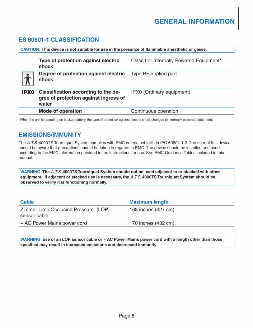
ES 60601-1 CLASSIFICATION
CAUTION: This device is not suitable for use in the presence of fl ammable anesthetic or gases.
Type of protection against electric
shockClass I or Internally Powered Equipment*
Degree of protection against electric
shockType BF applied part.
IPX0 Classifi cation according to the de-
gree of protection against ingress of
water
IPX0 (Ordinary equipment).
Mode of operation Continuous operation.
*When the unit is operating on backup battery, the type of protection against electric shock changes to internally powered equipment.
EMISSIONS/IMMUNITY
The A.T.S. 4000TS Tourniquet System complies with EMC criteria set forth in IEC 60601-1-2. The user of this device should be aware that precautions should be taken in regards to EMC. The device should be installed and used according to the EMC information provided in the instructions for use. See EMC Guidance Tables included in this manual.
WARNING: The A.T.S. 4000TS Tourniquet System should not be used adjacent to or stacked with other
equipment. If adjacent or stacked use is necessary, the A.T.S. 4000TS Tourniquet System should be
observed to verify it is functioning normally.
Cable Maximum length
Zimmer Limb Occlusion Pressure (LOP)
sensor cable
168 inches (427 cm).
~ AC Power Mains power cord 170 inches (432 cm).
WARNING: use of an LOP sensor cable or ~ AC Power Mains power cord with a length other than those
specifi ed may result in increased emissions and decreased immunity.
Page 9
INSTALLATION AND OPERATING INSTRUCTIONS
INSTALLATION AND OPERATING INSTRUCTIONS
INITIAL VISUAL INSPECTION
Unpack the A.T.S. 4000TS Tourniquet upon receipt and inspect the unit for any obvious damage that may have
occurred during shipment including damage to any accessories. We recommend that this inspection be performed
by a qualifi ed biomedical engineer or other person thoroughly familiar with electronic medical devices. If the unit
is damaged, notify the carrier and your Zimmer representative immediately. If the initial inspection results are
satisfactory, a functional and calibration check should be performed after a 10-hour charge.
CAUTION: The A.T.S. 4000TS Tourniquet System is intended to be used outside the sterile fi eld.
FEATURES AND OPERATING PRINCIPLES
The A.T.S.4000TS has a variety of features and physical characteristics as described below.
BUTTONS AND ICONS
Various colored buttons and icons are used in the A.T.S. 4000TS and described below. Please refer to Touchscreen GUI below for details on what the colors mean.
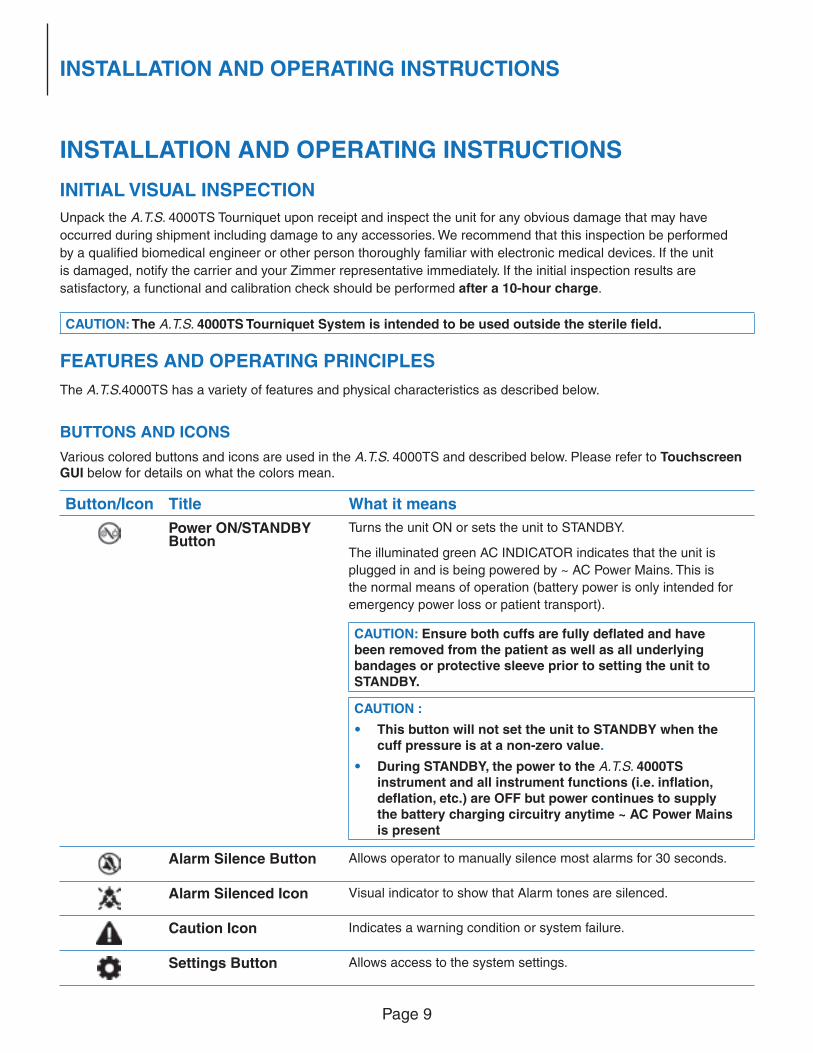
Button/Icon Title What it means
Power ON/STANDBY Button
Turns the unit ON or sets the unit to STANDBY.
The illuminated green AC INDICATOR indicates that the unit is
plugged in and is being powered by ~ AC Power Mains. This is
the normal means of operation (battery power is only intended for
emergency power loss or patient transport).
CAUTION: Ensure both cuffs are fully defl ated and have been removed from the patient as well as all underlying bandages or protective sleeve prior to setting the unit to STANDBY.
CAUTION :
• This button will not set the unit to STANDBY when the cuff pressure is at a non-zero value.
• During STANDBY, the power to the A.T.S. 4000TS instrument and all instrument functions (i.e. infl ation, defl ation, etc.) are OFF but power continues to supply the battery charging circuitry anytime ~ AC Power Mains is present
Alarm Silence Button Allows operator to manually silence most alarms for 30 seconds.
Alarm Silenced Icon Visual indicator to show that Alarm tones are silenced.
Caution Icon Indicates a warning condition or system failure.
Settings Button Allows access to the system settings.
Page 10
INSTALLATION AND OPERATING INSTRUCTIONS
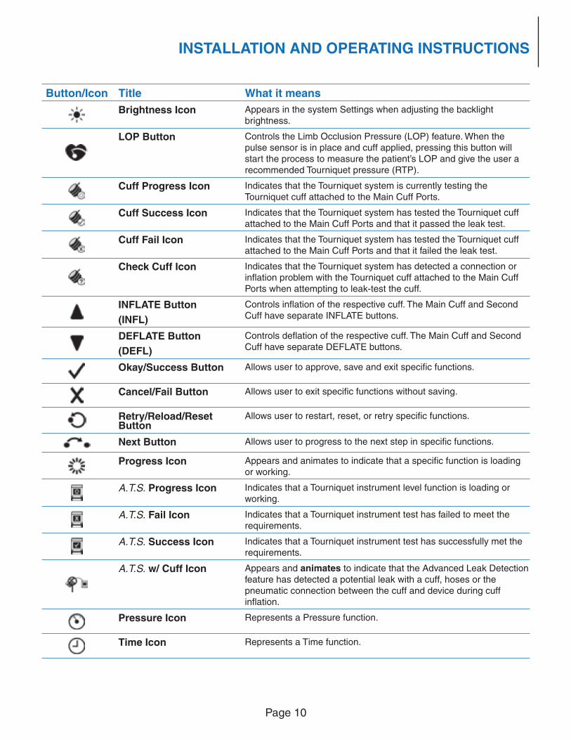
Button/Icon Title What it means
Brightness Icon Appears in the system Settings when adjusting the backlight brightness.
LOP Button Controls the Limb Occlusion Pressure (LOP) feature. When the pulse sensor is in place and cuff applied, pressing this button will start the process to measure the patient’s LOP and give the user a recommended Tourniquet pressure (RTP).
Cuff Progress Icon Indicates that the Tourniquet system is currently testing the Tourniquet cuff attached to the Main Cuff Ports.
Cuff Success Icon Indicates that the Tourniquet system has tested the Tourniquet cuff attached to the Main Cuff Ports and that it passed the leak test.
Cuff Fail Icon Indicates that the Tourniquet system has tested the Tourniquet cuff attached to the Main Cuff Ports and that it failed the leak test.
Check Cuff Icon Indicates that the Tourniquet system has detected a connection or infl ation problem with the Tourniquet cuff attached to the Main Cuff Ports when attempting to leak-test the cuff.
INFLATE Button
(INFL)
Controls infl ation of the respective cuff. The Main Cuff and Second Cuff have separate INFLATE buttons.
DEFLATE Button
(DEFL)
Controls defl ation of the respective cuff. The Main Cuff and Second Cuff have separate DEFLATE buttons.
Okay/Success Button Allows user to approve, save and exit specifi c functions.
Cancel/Fail Button Allows user to exit specifi c functions without saving.
Retry/Reload/Reset Button
Allows user to restart, reset, or retry specifi c functions.
Next Button Allows user to progress to the next step in specifi c functions.
Progress Icon Appears and animates to indicate that a specifi c function is loading or working.
A.T.S. Progress Icon Indicates that a Tourniquet instrument level function is loading or working.
A.T.S. Fail Icon Indicates that a Tourniquet instrument test has failed to meet the requirements.
A.T.S. Success Icon Indicates that a Tourniquet instrument test has successfully met the requirements.
A.T.S. w/ Cuff Icon Appears and animates to indicate that the Advanced Leak Detection feature has detected a potential leak with a cuff, hoses or the pneumatic connection between the cuff and device during cuff infl ation.
Pressure Icon Represents a Pressure function.
Time Icon Represents a Time function.
Page 11
INSTALLATION AND OPERATING INSTRUCTIONS
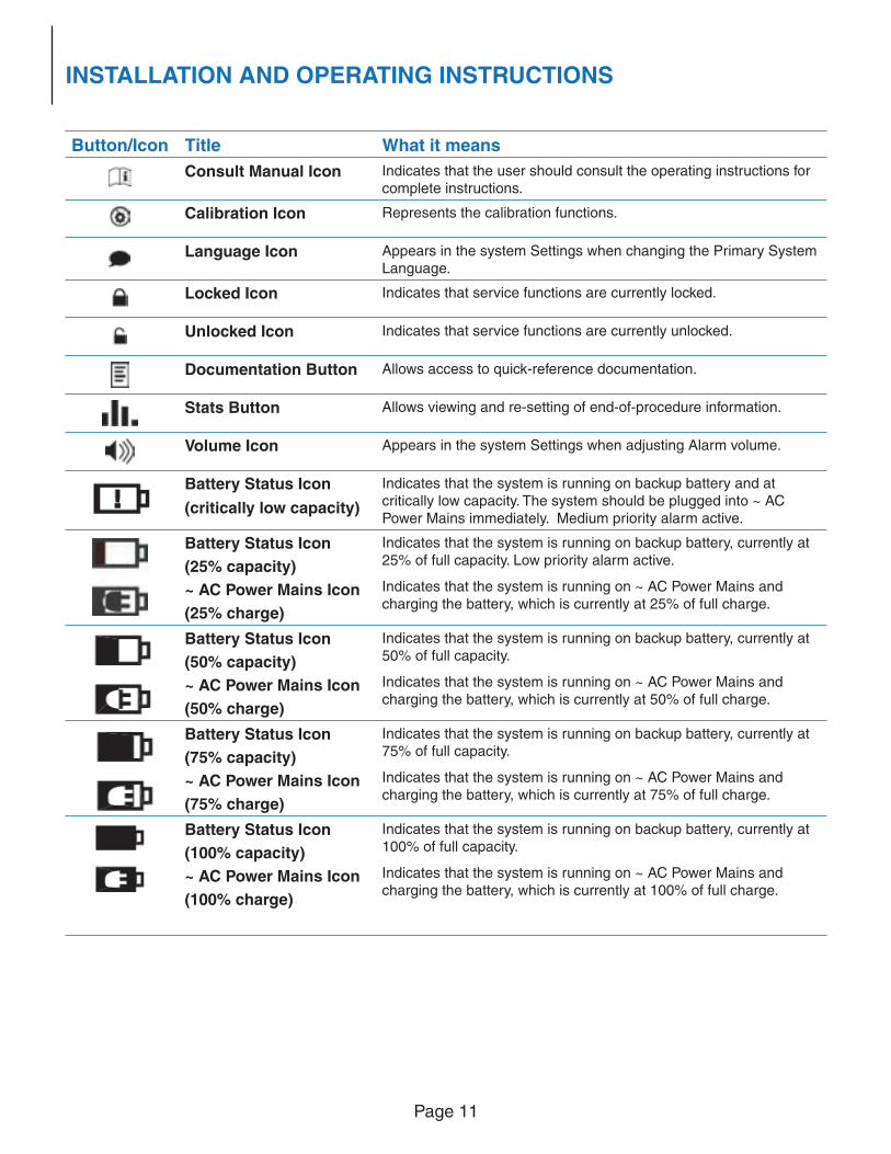
Button/Icon Title What it means
Consult Manual Icon Indicates that the user should consult the operating instructions for complete instructions.
Calibration Icon Represents the calibration functions.
Language Icon Appears in the system Settings when changing the Primary System Language.
Locked Icon Indicates that service functions are currently locked.
Unlocked Icon Indicates that service functions are currently unlocked.
Documentation Button Allows access to quick-reference documentation.
Stats Button Allows viewing and re-setting of end-of-procedure information.
Volume Icon Appears in the system Settings when adjusting Alarm volume.
Battery Status Icon
(critically low capacity)
Indicates that the system is running on backup battery and at critically low capacity. The system should be plugged into ~ AC Power Mains immediately. Medium priority alarm active.
Battery Status Icon
(25% capacity)
~ AC Power Mains Icon
(25% charge)
Indicates that the system is running on backup battery, currently at 25% of full capacity. Low priority alarm active.
Indicates that the system is running on ~ AC Power Mains and charging the battery, which is currently at 25% of full charge.
Battery Status Icon
(50% capacity)
~ AC Power Mains Icon
(50% charge)
Indicates that the system is running on backup battery, currently at 50% of full capacity.
Indicates that the system is running on ~ AC Power Mains and charging the battery, which is currently at 50% of full charge.
Battery Status Icon
(75% capacity)
~ AC Power Mains Icon
(75% charge)
Indicates that the system is running on backup battery, currently at
75% of full capacity.
Indicates that the system is running on ~ AC Power Mains and charging the battery, which is currently at 75% of full charge.
Battery Status Icon
(100% capacity)
~ AC Power Mains Icon
(100% charge)
Indicates that the system is running on backup battery, currently at 100% of full capacity.
Indicates that the system is running on ~ AC Power Mains and charging the battery, which is currently at 100% of full charge.
Page 12
INSTALLATION AND OPERATING INSTRUCTIONS
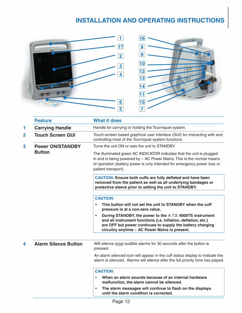
Feature What it does
1 Carrying Handle Handle for carrying or holding the Tourniquet system.
2 Touch Screen GUI Touch-screen based graphical user interface (GUI) for interacting with and controlling most of the Tourniquet system functions.
3 Power ON/STANDBY Button
Turns the unit ON or sets the unit to STANDBY.
The illuminated green AC INDICATOR indicates that the unit is plugged
in and is being powered by ~ AC Power Mains. This is the normal means
of operation (battery power is only intended for emergency power loss or
patient transport).
CAUTION: Ensure both cuffs are fully defl ated and have been removed from the patient as well as all underlying bandages or protective sleeve prior to setting the unit to STANDBY.
CAUTION:
• This button will not set the unit to STANDBY when the cuff pressure is at a non-zero value.
• During STANDBY, the power to the A.T.S. 4000TS instrument and all instrument functions (i.e. infl ation, defl ation, etc.) are OFF but power continues to supply the battery charging circuitry anytime ~ AC Power Mains is present.
4 Alarm Silence Button Will silence most audible alarms for 30 seconds after the button is pressed.
An alarm silenced icon will appear in the cuff status display to indicate the alarm is silenced. Alarms will silence after the full priority tone has played.
CAUTION:
• When an alarm sounds because of an internal hardware malfunction, the alarm cannot be silenced.
• The alarm messages will continue to fl ash on the displays until the alarm condition is corrected.
4
10
9
12
13
14
11
156
75
1
17
2
3
16
8
Page 13
INSTALLATION AND OPERATING INSTRUCTIONS
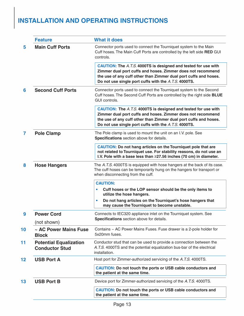
Feature What it does
5 Main Cuff Ports Connector ports used to connect the Tourniquet system to the Main
Cuff hoses. The Main Cuff Ports are controlled by the left side RED GUI
controls.
CAUTION: The A.T.S. 4000TS is designed and tested for use with
Zimmer dual port cuffs and hoses. Zimmer does not recommend
the use of any cuff other than Zimmer dual port cuffs and hoses.
Do not use single port cuffs with the A.T.S. 4000TS.
6 Second Cuff Ports Connector ports used to connect the Tourniquet system to the Second
Cuff hoses. The Second Cuff Ports are controlled by the right side BLUE
GUI controls.
CAUTION: The A.T.S. 4000TS is designed and tested for use with
Zimmer dual port cuffs and hoses. Zimmer does not recommend
the use of any cuff other than Zimmer dual port cuffs and hoses.
Do not use single port cuffs with the A.T.S. 4000TS.
7 Pole Clamp The Pole clamp is used to mount the unit on an I.V. pole. See
Specifi cations section above for details.
CAUTION: Do not hang articles on the Tourniquet pole that are not related to Tourniquet use. For stability reasons, do not use an I.V. Pole with a base less than ≥27.56 inches (70 cm) in diameter.
8 Hose Hangers The A.T.S. 4000TS is equipped with hose hangers at the back of its case. The cuff hoses can be temporarily hung on the hangers for transport or when disconnecting from the cuff.
CAUTION:
• Cuff hoses or the LOP sensor should be the only items to utilize the hose hangers.
• Do not hang articles on the Tourniquet’s hose hangers that
may cause the Tourniquet to become unstable.
9 Power Cord
(not shown)
Connects to IEC320 appliance inlet on the Tourniquet system. See
Specifi cations section above for details.
10 ~ AC Power Mains Fuse
Block
Contains ~ AC Power Mains Fuses. Fuse drawer is a 2-pole holder for
5x20mm fuses.
11 Potential Equalization
Conductor Stud
Conductor stud that can be used to provide a connection between the
A.T.S. 4000TS and the potential equalization bus-bar of the electrical
installation.
12 USB Port A Host port for Zimmer-authorized servicing of the A.T.S. 4000TS.
CAUTION: Do not touch the ports or USB cable conductors and the patient at the same time.
13 USB Port B Device port for Zimmer-authorized servicing of the A.T.S. 4000TS.
CAUTION: Do not touch the ports or USB cable conductors and the patient at the same time.
Page 14
INSTALLATION AND OPERATING INSTRUCTIONS
Feature What it does
14 LOP Sensor Port Port used to connect the Zimmer LOP sensor.
15 LOP Sensor Storage Recess area used to store the LOP sensor when not in use.
16 Battery Compartment Compartment that holds the A.T.S. 4000TS’s backup battery.
17 Alarm/Warning Light Alarm priority indicator. This light will fl ash and change color to yellow or
red depending on the alarm priority (see Alarm Conditions section for
details).
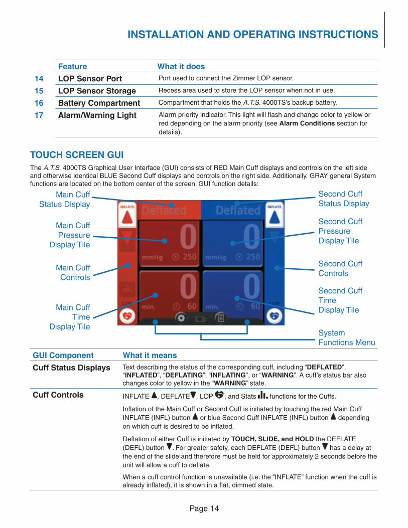
TOUCH SCREEN GUI
The A.T.S. 4000TS Graphical User Interface (GUI) consists of RED Main Cuff displays and controls on the left side and otherwise identical BLUE Second Cuff displays and controls on the right side. Additionally, GRAY general System functions are located on the bottom center of the screen. GUI function details:
GUI Component What it means
Cuff Status Displays Text describing the status of the corresponding cuff, including “DEFLATED”, “INFLATED”, “DEFLATING”, “INFLATING”, or “WARNING”. A cuff’s status bar also changes color to yellow in the “WARNING” state.
Cuff Controls INFLATE , DEFLATE , LOP , and Stats functions for the Cuffs.
Infl ation of the Main Cuff or Second Cuff is initiated by touching the red Main Cuff
INFLATE (INFL) button or blue Second Cuff INFLATE (INFL) button depending
on which cuff is desired to be infl ated.
Defl ation of either Cuff is initiated by TOUCH, SLIDE, and HOLD the DEFLATE
(DEFL) button . For greater safety, each DEFLATE (DEFL) button has a delay at
the end of the slide and therefore must be held for approximately 2 seconds before the
unit will allow a cuff to defl ate.
When a cuff control function is unavailable (i.e. the “INFLATE” function when the cuff is already infl ated), it is shown in a fl at, dimmed state.
Main Cuff
Status Display
Main CuffPressure
Display Tile
Main CuffControls
Main CuffTime
Display Tile
Second Cuff
Status Display
Second CuffPressureDisplay Tile
Second Cuff Controls
Second CuffTimeDisplay Tile
SystemFunctions Menu
Page 15
INSTALLATION AND OPERATING INSTRUCTIONS
GUI Component What it means
System Functions
MenuSettings button , documentation button , and power status (Backup Battery or ~ AC Power Mains – see Buttons and Icons section above).
Cuff Pressure
Display Tiles
Touch to modify set pressure.
During normal operation with no buttons being touched, each of the independent
PRESSURE display areas will show the actual cuff pressure as well as the set-point
in smaller digits at the lower right side of a tile. At other times, depending on alarm
conditions and buttons touched, the display may communicate other information such
as alarm messages, set pressure, or end of procedure Stats.
Cuff Time Display
Tiles
Touch to modify set time.
During normal operation with no buttons being touched, each of the independent
TIME display areas will show elapsed infl ation time of each cuff as well as the set-
point in smaller digits at the lower right side of a tile. At other times the display will
communicate time alarm messages.
CAUTION:
• To prevent accidental timer reset, the elapsed infl ation time can only be “zeroed” when the cuff is fully defl ated or reset in the Stats feature.
• Additional time can be added to clear a time alarm.
INITIAL SETUP
WARNING: To avoid the RISK of electric shock, this equipment must only be connected to an ~ AC Power
Mains with protective earth.
The A.T.S. 4000TS should be plugged into ~ AC Power Mains for 10 hours before initial setup to ensure the backup
battery is fully charged. During shipping and storage, the unit’s battery could become weak. Always charge the
system 10 hours before initial setup, including calibration checking procedures, initial checks, tests and any institution-
performed biomedical evaluations.
TESTS AND CHECKS
The unit shall produce the results explained in the following steps exactly as indicated. Failure to do so indicates that
a problem may exist and the device is not to be used until necessary repair or calibration has been made. Refer to
Alarm Conditions or Maintenance sections as appropriate.
AUTOMATIC DIAGNOSTIC AND CALIBRATION CHECK
These automatic checks verify certain System Functions through diagnostics and calibration to system standards.1 Connect the power plug of the unit to a properly polarized and grounded power source with voltage and frequency
characteristics compatible with the Specifi cations section listed above. Observe that the green ~ AC Power
Mains indicator light turns on and illuminates the Power button in STANDBY mode.
2 Turn the unit ON by pressing the Power button and observe the following:
• The Zimmer circle “Z” icon and an animated Progress icon appear on the LCD display.
• The unit displays “A.T.S. 4000TS”. The unit is self-testing specifi c system hardware and software.
Page 16
INSTALLATION AND OPERATING INSTRUCTIONS
• The animated Progress icon is replaced by the text “DIAGNOSTIC OKAY.”
• “CALIBRATION” and an animated Progress icon are displayed during the calibration check. Once complete, “CALIBRATION OKAY” replaces the previous text and icon.
CAUTION: The A.T.S. 4000TS will automatically perform an internal Diagnostic and Calibration check when powered ON. Setting the system to STANDBY and powering back ON between cases will allow the system to re-perform the automatic Diagnostic and Calibration check.
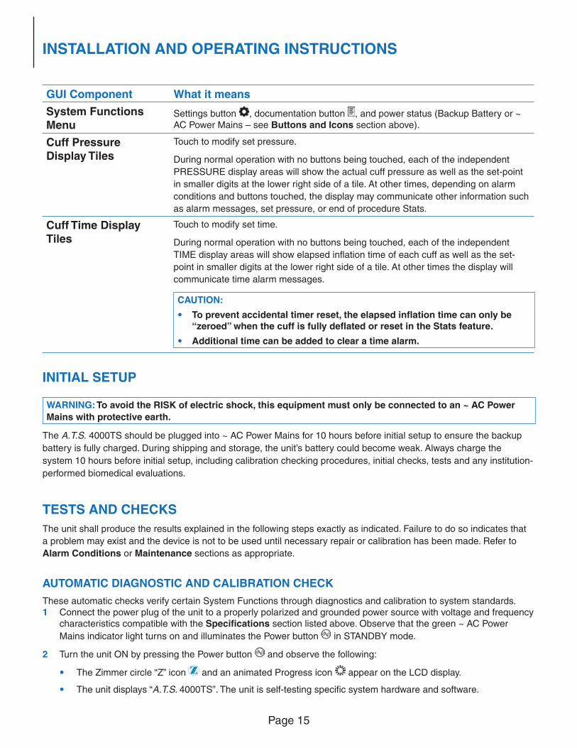
• After the startup routine is complete, the default Graphical User Interface (GUI) appears:
• “0” is indicated in the PRESSURE and TIME tiles of both the Main and Second displays.
• The default pressure is shown on both PRESSURE tiles. The default pressure is pre-set to 250 mmHg. This setting may be changed as desired.
• The default time is shown on both TIME tiles. The default time is pre-set to 60 minutes. This setting may be changed as desired.
CAUTION:
• If “CALIBRATION ERROR” is displayed, refer to the Calibration Error at Power-On section with the Maintenance section.
• If a number other than zero is indicated in the PRESSURE displays, the unit should be calibrated by a qualifi ed biomedical engineer or other person thoroughly familiar with electronic medical devices via the Calibration section within the Maintenance section.
MANUAL TESTS AND CHECKS
These manual tests and checks verify certain System Functions and include Pressure and Time set-point tests and
Calibration and Low Pressure Alarm checks.
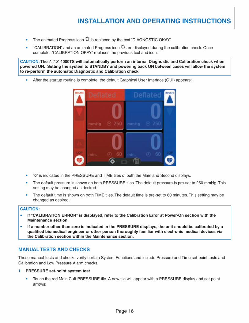
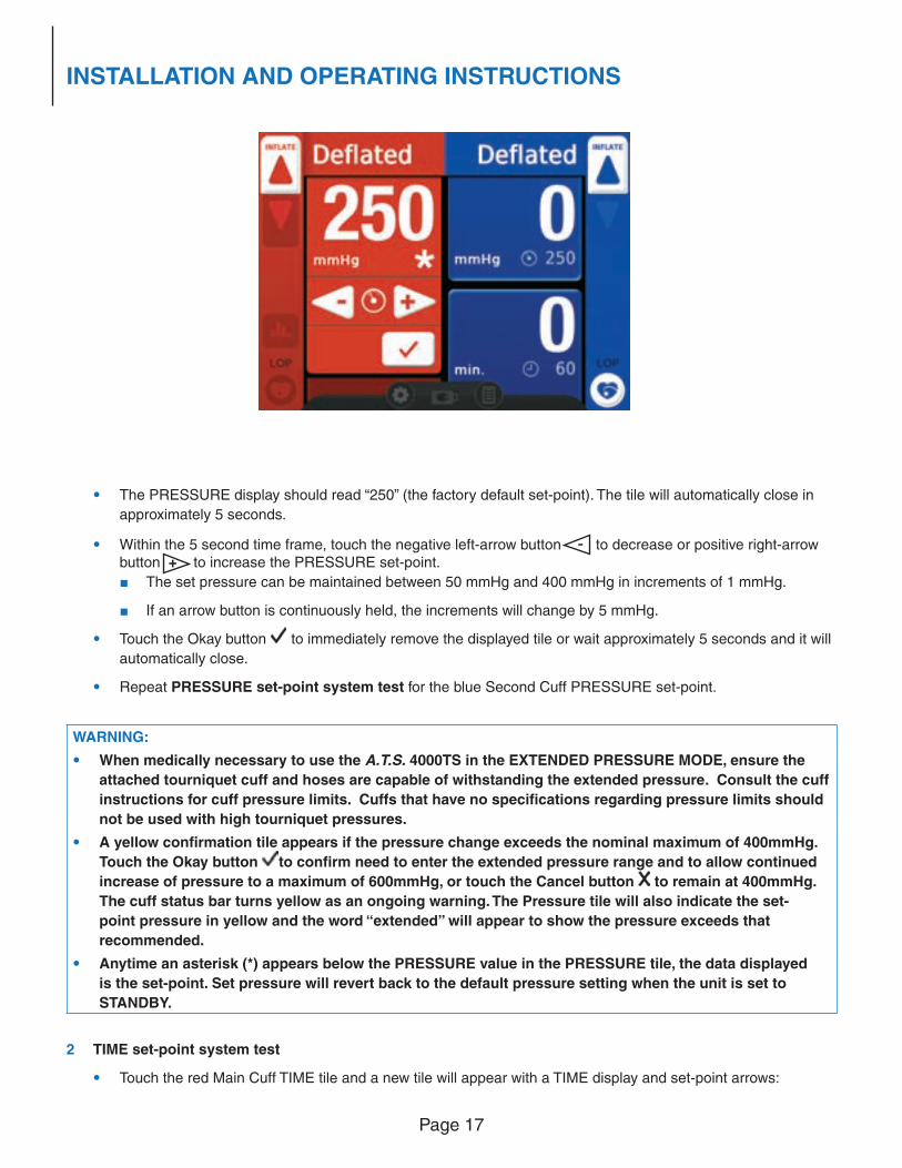
1 PRESSURE set-point system test
• Touch the red Main Cuff PRESSURE tile. A new tile will appear with a PRESSURE display and set-point
arrows:
Page 17
INSTALLATION AND OPERATING INSTRUCTIONS
• The PRESSURE display should read “250” (the factory default set-point). The tile will automatically close in
approximately 5 seconds.
• Within the 5 second time frame, touch the negative left-arrow button - to decrease or positive right-arrow button + to increase the PRESSURE set-point.
■ The set pressure can be maintained between 50 mmHg and 400 mmHg in increments of 1 mmHg.
■ If an arrow button is continuously held, the increments will change by 5 mmHg.
• Touch the Okay button to immediately remove the displayed tile or wait approximately 5 seconds and it will
automatically close.
• Repeat PRESSURE set-point system test for the blue Second Cuff PRESSURE set-point.
WARNING:
• When medically necessary to use the A.T.S. 4000TS in the EXTENDED PRESSURE MODE, ensure the
attached tourniquet cuff and hoses are capable of withstanding the extended pressure. Consult the cuff
instructions for cuff pressure limits. Cuffs that have no specifi cations regarding pressure limits should
not be used with high tourniquet pressures.
• A yellow confi rmation tile appears if the pressure change exceeds the nominal maximum of 400mmHg.
Touch the Okay button to confi rm need to enter the extended pressure range and to allow continued
increase of pressure to a maximum of 600mmHg, or touch the Cancel button to remain at 400mmHg.
The cuff status bar turns yellow as an ongoing warning. The Pressure tile will also indicate the set-
point pressure in yellow and the word “extended” will appear to show the pressure exceeds that
recommended.
• Anytime an asterisk (*) appears below the PRESSURE value in the PRESSURE tile, the data displayed
is the set-point. Set pressure will revert back to the default pressure setting when the unit is set to
STANDBY.
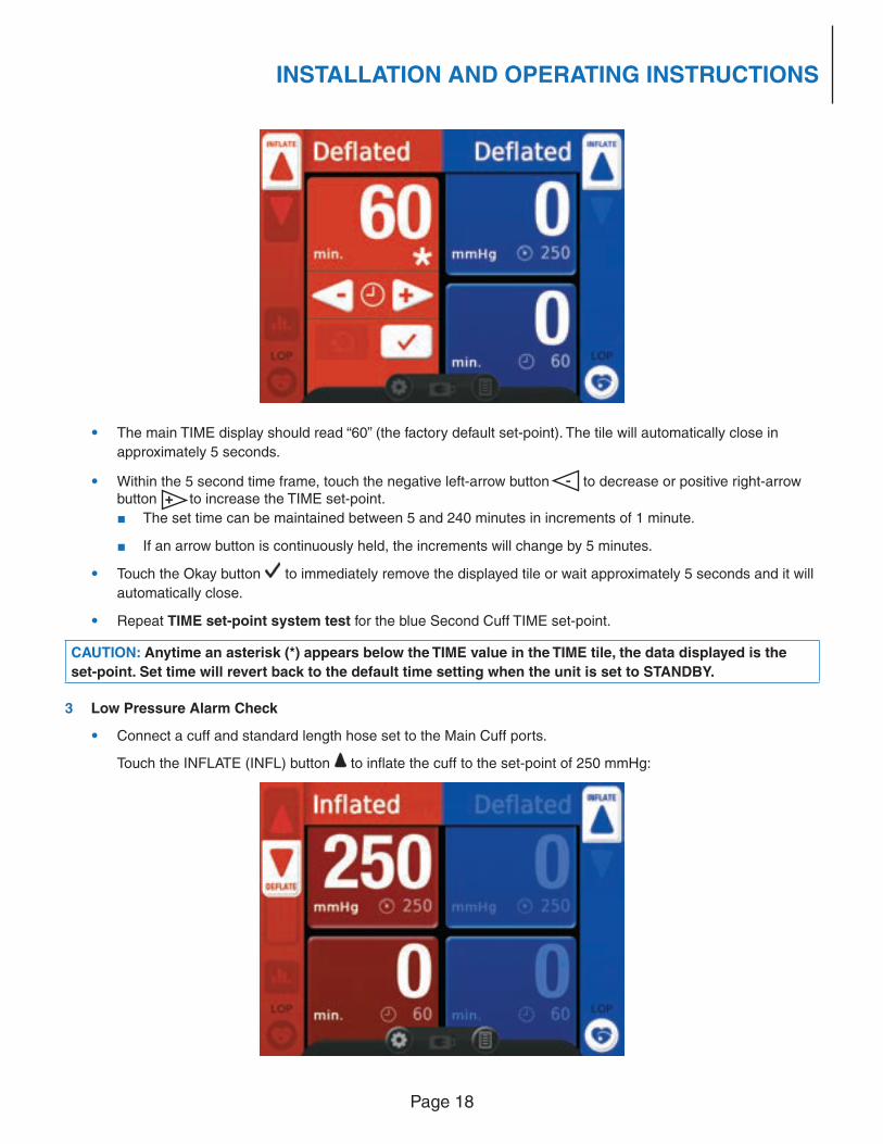
2 TIME set-point system test
• Touch the red Main Cuff TIME tile and a new tile will appear with a TIME display and set-point arrows:
Page 18
INSTALLATION AND OPERATING INSTRUCTIONS
• The main TIME display should read “60” (the factory default set-point). The tile will automatically close in
approximately 5 seconds.
• Within the 5 second time frame, touch the negative left-arrow button - to decrease or positive right-arrow button + to increase the TIME set-point.
■ The set time can be maintained between 5 and 240 minutes in increments of 1 minute.
■ If an arrow button is continuously held, the increments will change by 5 minutes.
• Touch the Okay button to immediately remove the displayed tile or wait approximately 5 seconds and it will
automatically close.
• Repeat TIME set-point system test for the blue Second Cuff TIME set-point.
CAUTION: Anytime an asterisk (*) appears below the TIME value in the TIME tile, the data displayed is the
set-point. Set time will revert back to the default time setting when the unit is set to STANDBY.
3 Low Pressure Alarm Check
• Connect a cuff and standard length hose set to the Main Cuff ports.
Touch the INFLATE (INFL) button to infl ate the cuff to the set-point of 250 mmHg:
Page 19
INSTALLATION AND OPERATING INSTRUCTIONS
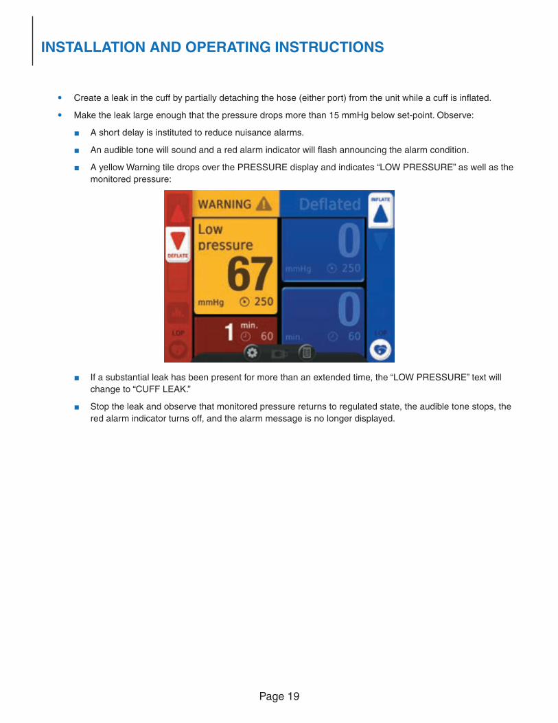
• Create a leak in the cuff by partially detaching the hose (either port) from the unit while a cuff is infl ated.
• Make the leak large enough that the pressure drops more than 15 mmHg below set-point. Observe:
■ A short delay is instituted to reduce nuisance alarms.
■ An audible tone will sound and a red alarm indicator will fl ash announcing the alarm condition.
■ A yellow Warning tile drops over the PRESSURE display and indicates “LOW PRESSURE” as well as the
monitored pressure:
■ If a substantial leak has been present for more than an extended time, the “LOW PRESSURE” text will
change to “CUFF LEAK.”
■ Stop the leak and observe that monitored pressure returns to regulated state, the audible tone stops, the
red alarm indicator turns off, and the alarm message is no longer displayed.
Page 20
INSTALLATION AND OPERATING INSTRUCTIONS
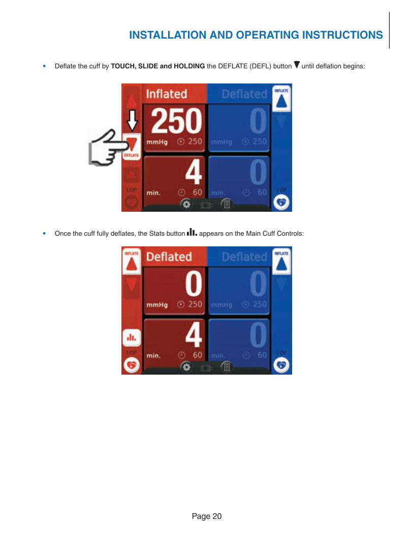
• Defl ate the cuff by TOUCH, SLIDE and HOLDING the DEFLATE (DEFL) button until defl ation begins:
• Once the cuff fully defl ates, the Stats button appears on the Main Cuff Controls:
Page 21
INSTALLATION AND OPERATING INSTRUCTIONS
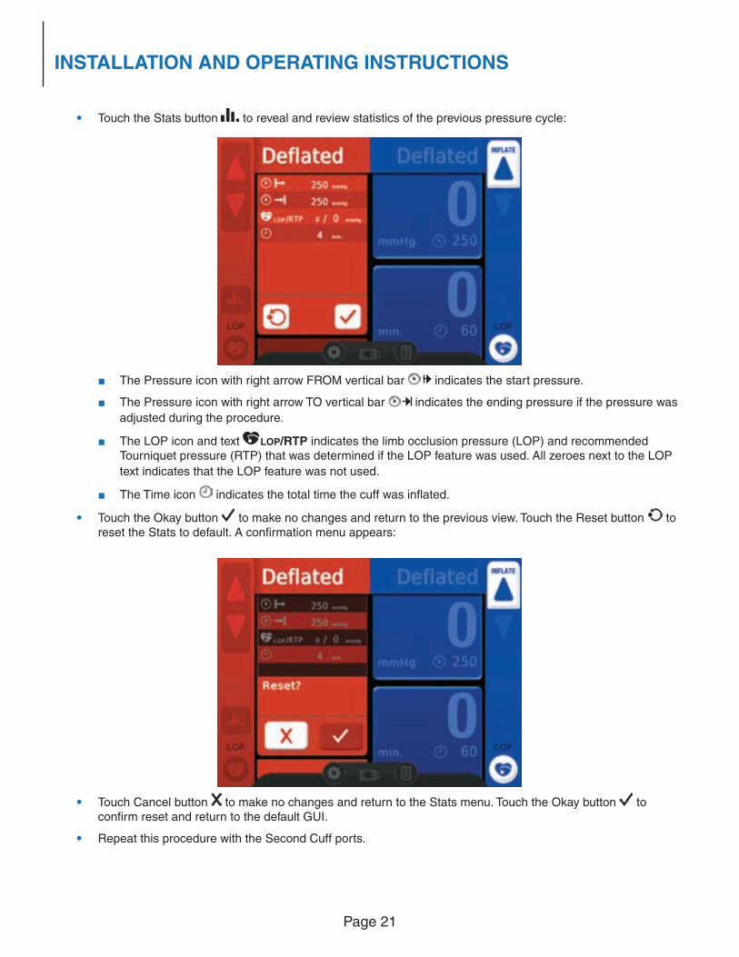
• Touch the Stats button to reveal and review statistics of the previous pressure cycle:
■ The Pressure icon with right arrow FROM vertical bar indicates the start pressure.
■ The Pressure icon with right arrow TO vertical bar indicates the ending pressure if the pressure was
adjusted during the procedure.
■ The LOP icon and text LOP/RTP indicates the limb occlusion pressure (LOP) and recommended Tourniquet pressure (RTP) that was determined if the LOP feature was used. All zeroes next to the LOP
text indicates that the LOP feature was not used.
■ The Time icon indicates the total time the cuff was infl ated.
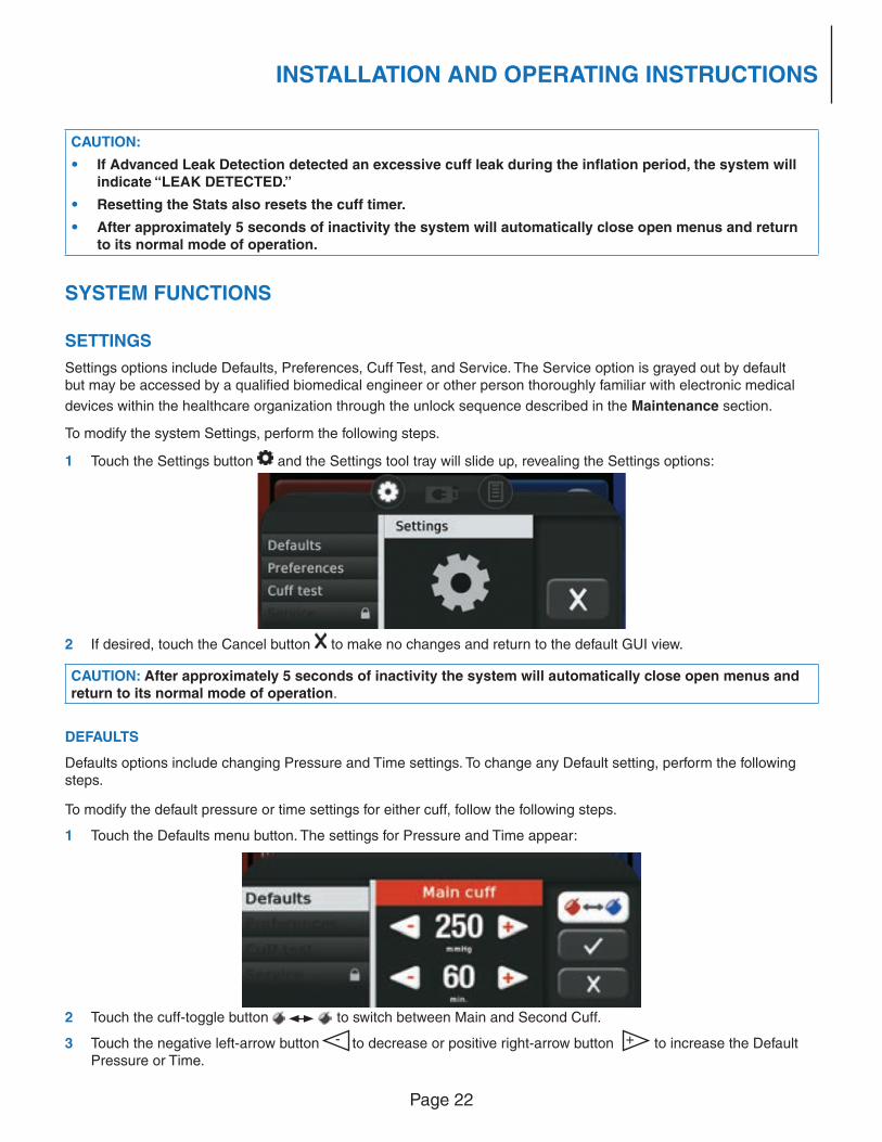
• Touch the Okay button to make no changes and return to the previous view. Touch the Reset button to reset the Stats to default. A confi rmation menu appears:
• Touch Cancel button to make no changes and return to the Stats menu. Touch the Okay button to confi rm reset and return to the default GUI.
• Repeat this procedure with the Second Cuff ports.
Page 22
INSTALLATION AND OPERATING INSTRUCTIONS
CAUTION:
• If Advanced Leak Detection detected an excessive cuff leak during the infl ation period, the system will indicate “LEAK DETECTED.”
• Resetting the Stats also resets the cuff timer.
• After approximately 5 seconds of inactivity the system will automatically close open menus and return to its normal mode of operation.
SYSTEM FUNCTIONS
SETTINGS
Settings options include Defaults, Preferences, Cuff Test, and Service. The Service option is grayed out by default but may be accessed by a qualifi ed biomedical engineer or other person thoroughly familiar with electronic medical
devices within the healthcare organization through the unlock sequence described in the Maintenance section.
To modify the system Settings, perform the following steps.
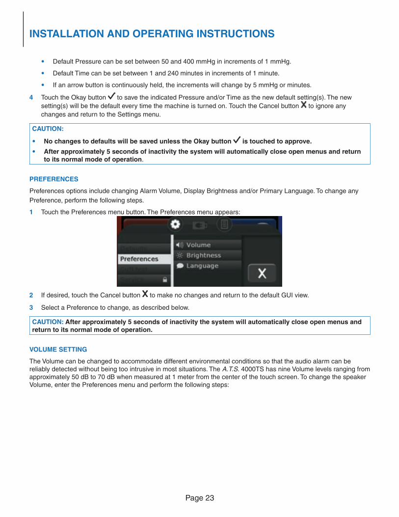
1 Touch the Settings button and the Settings tool tray will slide up, revealing the Settings options:
2 If desired, touch the Cancel button to make no changes and return to the default GUI view.
CAUTION: After approximately 5 seconds of inactivity the system will automatically close open menus and return to its normal mode of operation.
DEFAULTS
Defaults options include changing Pressure and Time settings. To change any Default setting, perform the following steps.
To modify the default pressure or time settings for either cuff, follow the following steps.
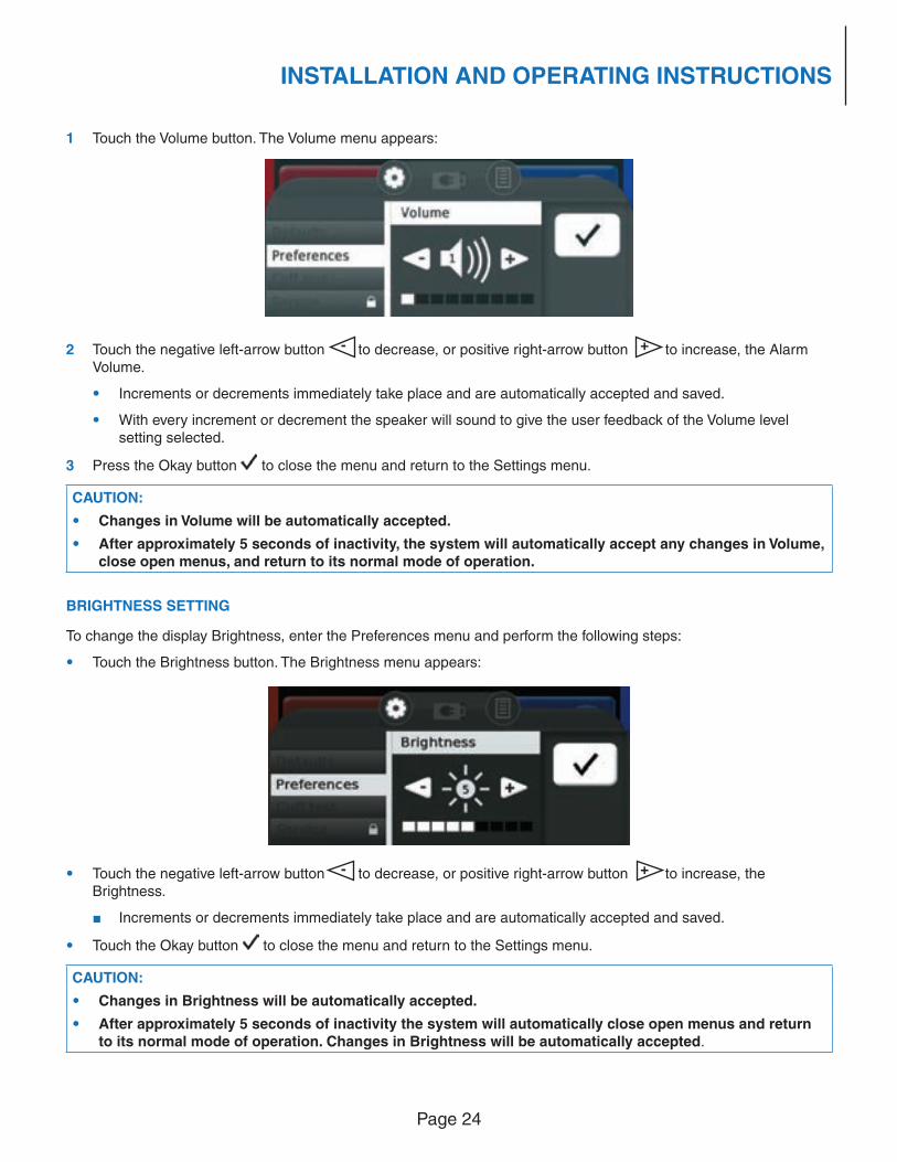
1 Touch the Defaults menu button. The settings for Pressure and Time appear:
2 Touch the cuff-toggle button to switch between Main and Second Cuff.
3 Touch the negative left-arrow button - to decrease or positive right-arrow button + to increase the Default Pressure or Time.
Page 23
INSTALLATION AND OPERATING INSTRUCTIONS
• Default Pressure can be set between 50 and 400 mmHg in increments of 1 mmHg.
• Default Time can be set between 1 and 240 minutes in increments of 1 minute.
• If an arrow button is continuously held, the increments will change by 5 mmHg or minutes.
4 Touch the Okay button to save the indicated Pressure and/or Time as the new default setting(s). The new
setting(s) will be the default every time the machine is turned on. Touch the Cancel button to ignore any
changes and return to the Settings menu.
CAUTION:
• No changes to defaults will be saved unless the Okay button is touched to approve.
• After approximately 5 seconds of inactivity the system will automatically close open menus and return to its normal mode of operation.
PREFERENCES
Preferences options include changing Alarm Volume, Display Brightness and/or Primary Language. To change any
Preference, perform the following steps.
1 Touch the Preferences menu button. The Preferences menu appears:
2 If desired, touch the Cancel button to make no changes and return to the default GUI view.
3 Select a Preference to change, as described below.
CAUTION: After approximately 5 seconds of inactivity the system will automatically close open menus and return to its normal mode of operation.
VOLUME SETTING
The Volume can be changed to accommodate different environmental conditions so that the audio alarm can be reliably detected without being too intrusive in most situations. The A.T.S. 4000TS has nine Volume levels ranging from approximately 50 dB to 70 dB when measured at 1 meter from the center of the touch screen. To change the speaker Volume, enter the Preferences menu and perform the following steps:
Page 24
INSTALLATION AND OPERATING INSTRUCTIONS
1 Touch the Volume button. The Volume menu appears:
2 Touch the negative left-arrow button - to decrease, or positive right-arrow button + to increase, the Alarm Volume.
• Increments or decrements immediately take place and are automatically accepted and saved.
• With every increment or decrement the speaker will sound to give the user feedback of the Volume level setting selected.
3 Press the Okay button to close the menu and return to the Settings menu.
CAUTION:
• Changes in Volume will be automatically accepted.
• After approximately 5 seconds of inactivity, the system will automatically accept any changes in Volume, close open menus, and return to its normal mode of operation.
BRIGHTNESS SETTING
To change the display Brightness, enter the Preferences menu and perform the following steps:
• Touch the Brightness button. The Brightness menu appears:
• Touch the negative left-arrow button - to decrease, or positive right-arrow button + to increase, the Brightness.
■ Increments or decrements immediately take place and are automatically accepted and saved.
• Touch the Okay button to close the menu and return to the Settings menu.
CAUTION:
• Changes in Brightness will be automatically accepted.
• After approximately 5 seconds of inactivity the system will automatically close open menus and return to its normal mode of operation. Changes in Brightness will be automatically accepted.
Page 25
INSTALLATION AND OPERATING INSTRUCTIONS
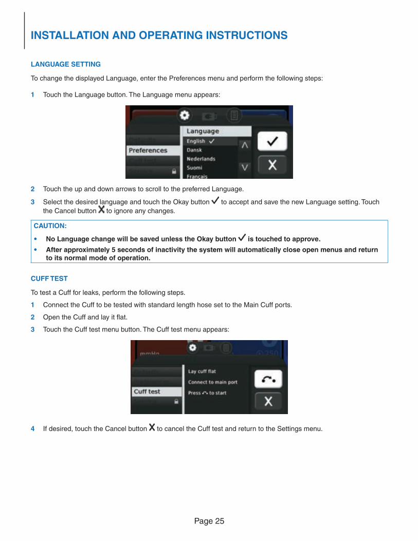
LANGUAGE SETTING
To change the displayed Language, enter the Preferences menu and perform the following steps:
1 Touch the Language button. The Language menu appears:
2 Touch the up and down arrows to scroll to the preferred Language.
3 Select the desired language and touch the Okay button to accept and save the new Language setting. Touch
the Cancel button to ignore any changes.
CAUTION:
• No Language change will be saved unless the Okay button is touched to approve.
• After approximately 5 seconds of inactivity the system will automatically close open menus and return to its normal mode of operation.
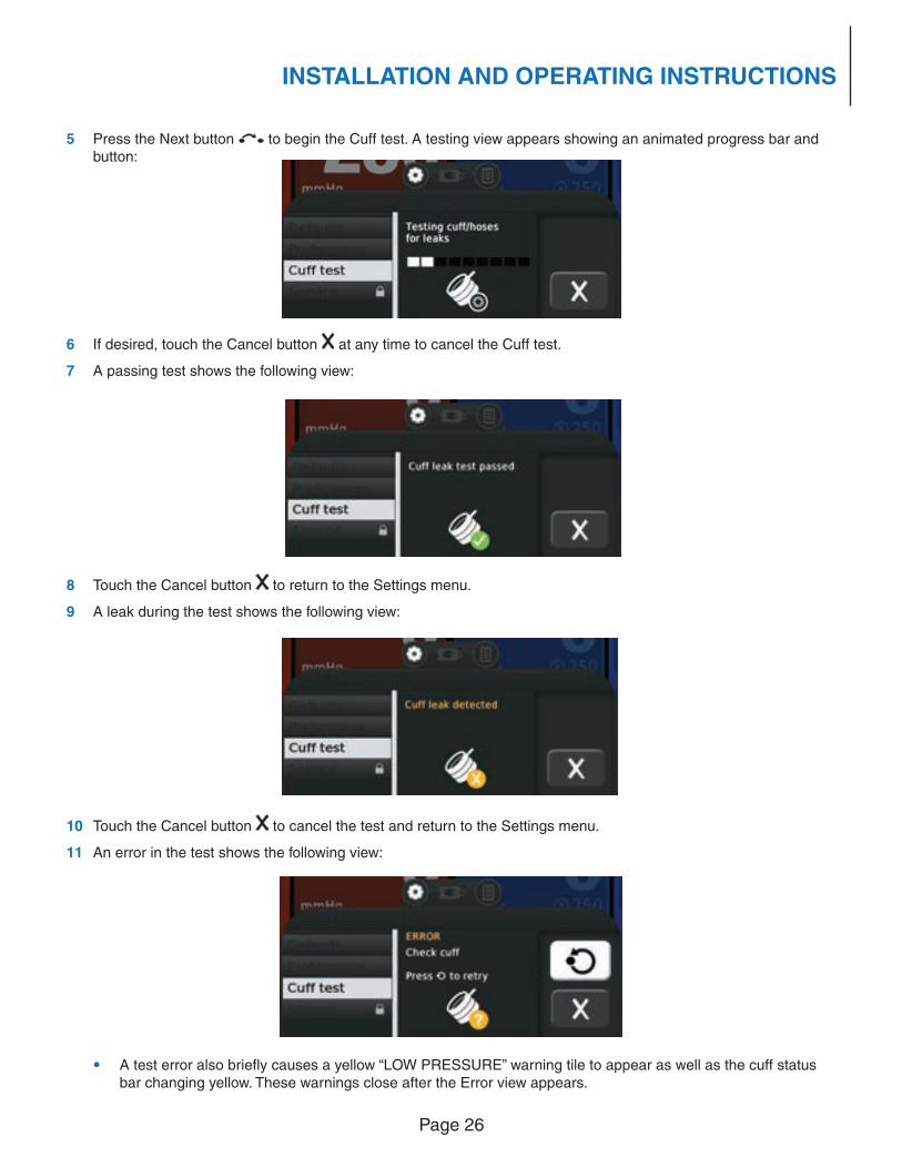
CUFF TEST
To test a Cuff for leaks, perform the following steps.
1 Connect the Cuff to be tested with standard length hose set to the Main Cuff ports.
2 Open the Cuff and lay it fl at.
3 Touch the Cuff test menu button. The Cuff test menu appears:
4 If desired, touch the Cancel button to cancel the Cuff test and return to the Settings menu.
Page 26
INSTALLATION AND OPERATING INSTRUCTIONS
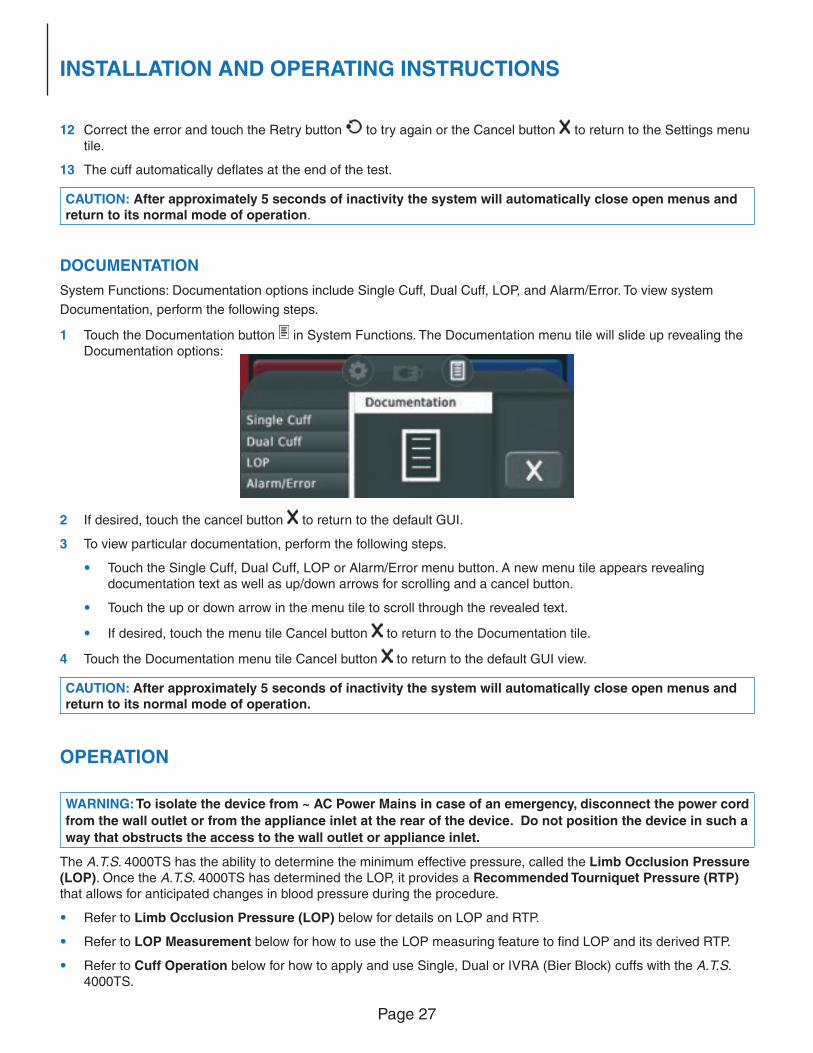
5 Press the Next button to begin the Cuff test. A testing view appears showing an animated progress bar and button:
6 If desired, touch the Cancel button at any time to cancel the Cuff test.
7 A passing test shows the following view:
8 Touch the Cancel button to return to the Settings menu.
9 A leak during the test shows the following view:
10 Touch the Cancel button to cancel the test and return to the Settings menu.
11 An error in the test shows the following view:
• A test error also briefl y causes a yellow “LOW PRESSURE” warning tile to appear as well as the cuff status bar changing yellow. These warnings close after the Error view appears.
Page 27
INSTALLATION AND OPERATING INSTRUCTIONS
12 Correct the error and touch the Retry button to try again or the Cancel button to return to the Settings menu tile.
13 The cuff automatically defl ates at the end of the test.
CAUTION: After approximately 5 seconds of inactivity the system will automatically close open menus and return to its normal mode of operation.
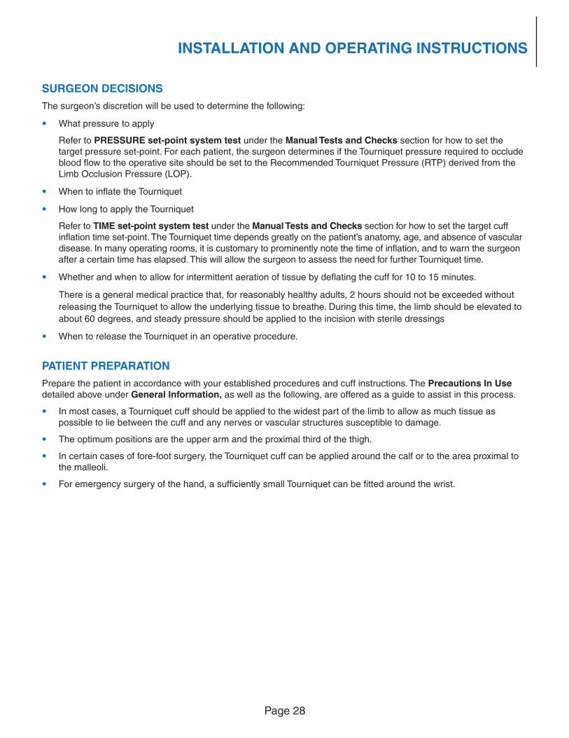
DOCUMENTATION
System Functions: Documentation options include Single Cuff, Dual Cuff, LOP, and Alarm/Error. To view system
Documentation, perform the following steps.
1 Touch the Documentation button in System Functions. The Documentation menu tile will slide up revealing the Documentation options:
2 If desired, touch the cancel button to return to the default GUI.
3 To view particular documentation, perform the following steps.
• Touch the Single Cuff, Dual Cuff, LOP or Alarm/Error menu button. A new menu tile appears revealing documentation text as well as up/down arrows for scrolling and a cancel button.
• Touch the up or down arrow in the menu tile to scroll through the revealed text.
• If desired, touch the menu tile Cancel button to return to the Documentation tile.
4 Touch the Documentation menu tile Cancel button to return to the default GUI view.
CAUTION: After approximately 5 seconds of inactivity the system will automatically close open menus and return to its normal mode of operation.
OPERATION
WARNING: To isolate the device from ~ AC Power Mains in case of an emergency, disconnect the power cord
from the wall outlet or from the appliance inlet at the rear of the device. Do not position the device in such a
way that obstructs the access to the wall outlet or appliance inlet.
The A.T.S. 4000TS has the ability to determine the minimum effective pressure, called the Limb Occlusion Pressure (LOP). Once the A.T.S. 4000TS has determined the LOP, it provides a Recommended Tourniquet Pressure (RTP) that allows for anticipated changes in blood pressure during the procedure.
• Refer to Limb Occlusion Pressure (LOP) below for details on LOP and RTP.
• Refer to LOP Measurement below for how to use the LOP measuring feature to fi nd LOP and its derived RTP.
• Refer to Cuff Operation below for how to apply and use Single, Dual or IVRA (Bier Block) cuffs with the A.T.S. 4000TS.
Page 28
INSTALLATION AND OPERATING INSTRUCTIONS
SURGEON DECISIONS
The surgeon’s discretion will be used to determine the following:
• What pressure to apply
Refer to PRESSURE set-point system test under the Manual Tests and Checks section for how to set the target pressure set-point. For each patient, the surgeon determines if the Tourniquet pressure required to occlude blood fl ow to the operative site should be set to the Recommended Tourniquet Pressure (RTP) derived from the Limb Occlusion Pressure (LOP).
• When to infl ate the Tourniquet
• How long to apply the Tourniquet
Refer to TIME set-point system test under the Manual Tests and Checks section for how to set the target cuff infl ation time set-point. The Tourniquet time depends greatly on the patient’s anatomy, age, and absence of vascular disease. In many operating rooms, it is customary to prominently note the time of infl ation, and to warn the surgeon after a certain time has elapsed. This will allow the surgeon to assess the need for further Tourniquet time.
• Whether and when to allow for intermittent aeration of tissue by defl ating the cuff for 10 to 15 minutes.
There is a general medical practice that, for reasonably healthy adults, 2 hours should not be exceeded without
releasing the Tourniquet to allow the underlying tissue to breathe. During this time, the limb should be elevated to
about 60 degrees, and steady pressure should be applied to the incision with sterile dressings
• When to release the Tourniquet in an operative procedure.
PATIENT PREPARATION
Prepare the patient in accordance with your established procedures and cuff instructions. The Precautions In Use detailed above under General Information, as well as the following, are offered as a guide to assist in this process.
• In most cases, a Tourniquet cuff should be applied to the widest part of the limb to allow as much tissue as possible to lie between the cuff and any nerves or vascular structures susceptible to damage.
• The optimum positions are the upper arm and the proximal third of the thigh.
• In certain cases of fore-foot surgery, the Tourniquet cuff can be applied around the calf or to the area proximal to the malleoli.
• For emergency surgery of the hand, a suffi ciently small Tourniquet can be fi tted around the wrist.
Page 29
INSTALLATION AND OPERATING INSTRUCTIONS
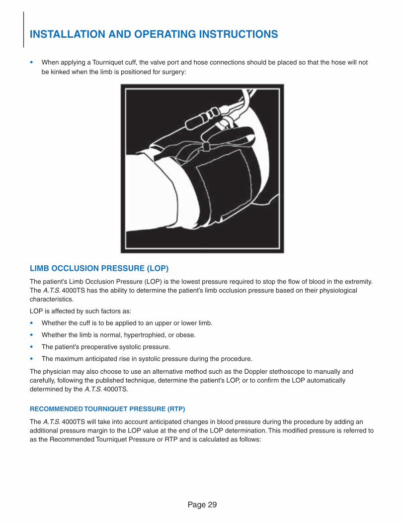
• When applying a Tourniquet cuff, the valve port and hose connections should be placed so that the hose will not
be kinked when the limb is positioned for surgery:
LIMB OCCLUSION PRESSURE (LOP)
The patient’s Limb Occlusion Pressure (LOP) is the lowest pressure required to stop the fl ow of blood in the extremity.
The A.T.S. 4000TS has the ability to determine the patient’s limb occlusion pressure based on their physiological
characteristics.
LOP is affected by such factors as:
• Whether the cuff is to be applied to an upper or lower limb.
• Whether the limb is normal, hypertrophied, or obese.
• The patient’s preoperative systolic pressure.
• The maximum anticipated rise in systolic pressure during the procedure.
The physician may also choose to use an alternative method such as the Doppler stethoscope to manually and
carefully, following the published technique, determine the patient’s LOP, or to confi rm the LOP automatically
determined by the A.T.S. 4000TS.
RECOMMENDED TOURNIQUET PRESSURE (RTP)
The A.T.S. 4000TS will take into account anticipated changes in blood pressure during the procedure by adding an
additional pressure margin to the LOP value at the end of the LOP determination. This modifi ed pressure is referred to
as the Recommended Tourniquet Pressure or RTP and is calculated as follows:
Page 30
INSTALLATION AND OPERATING INSTRUCTIONS
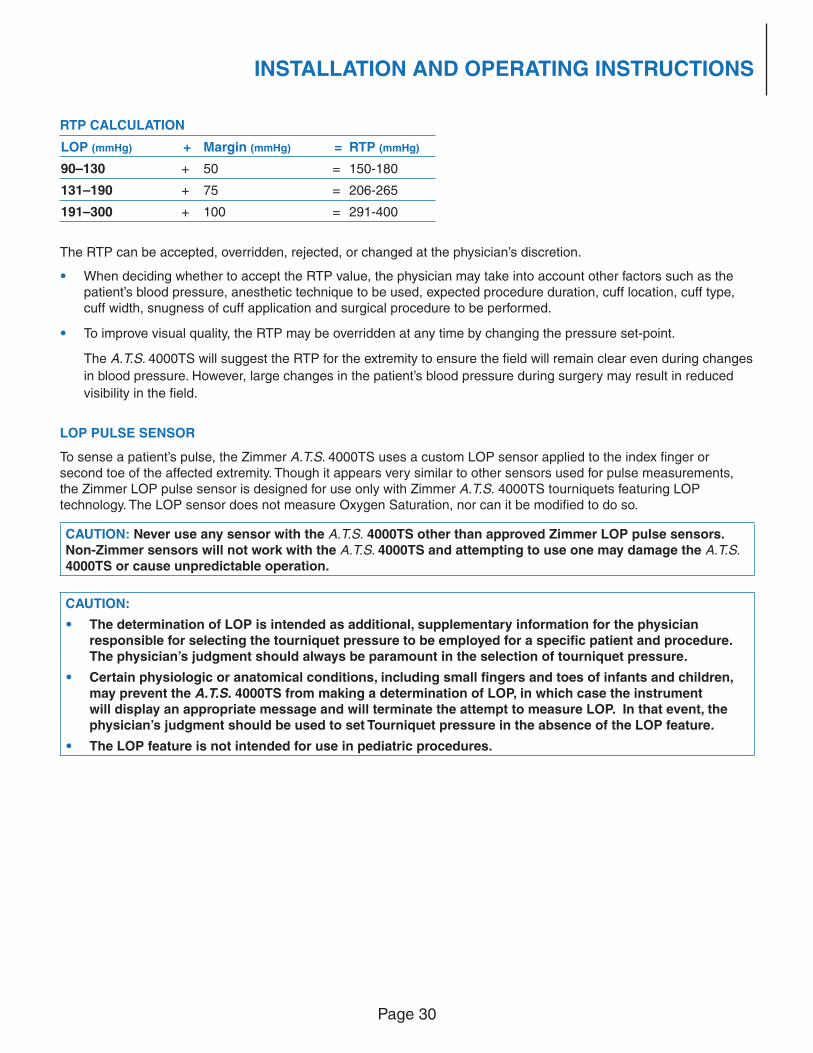
RTP CALCULATION
LOP (mmHg) + Margin (mmHg) = RTP (mmHg)
90–130 + 50 = 150-180
131–190 + 75 = 206-265
191–300 + 100 = 291-400
The RTP can be accepted, overridden, rejected, or changed at the physician’s discretion.
• When deciding whether to accept the RTP value, the physician may take into account other factors such as the patient’s blood pressure, anesthetic technique to be used, expected procedure duration, cuff location, cuff type, cuff width, snugness of cuff application and surgical procedure to be performed.
• To improve visual quality, the RTP may be overridden at any time by changing the pressure set-point.
The A.T.S. 4000TS will suggest the RTP for the extremity to ensure the fi eld will remain clear even during changes
in blood pressure. However, large changes in the patient’s blood pressure during surgery may result in reduced
visibility in the fi eld.
LOP PULSE SENSOR
To sense a patient’s pulse, the Zimmer A.T.S. 4000TS uses a custom LOP sensor applied to the index fi nger or second toe of the affected extremity. Though it appears very similar to other sensors used for pulse measurements, the Zimmer LOP pulse sensor is designed for use only with Zimmer A.T.S. 4000TS tourniquets featuring LOP technology. The LOP sensor does not measure Oxygen Saturation, nor can it be modifi ed to do so.
CAUTION: Never use any sensor with the A.T.S. 4000TS other than approved Zimmer LOP pulse sensors. Non-Zimmer sensors will not work with the A.T.S. 4000TS and attempting to use one may damage the A.T.S. 4000TS or cause unpredictable operation.
CAUTION:
• The determination of LOP is intended as additional, supplementary information for the physician responsible for selecting the tourniquet pressure to be employed for a specifi c patient and procedure. The physician’s judgment should always be paramount in the selection of tourniquet pressure.
• Certain physiologic or anatomical conditions, including small fi ngers and toes of infants and children, may prevent the A.T.S. 4000TS from making a determination of LOP, in which case the instrument will display an appropriate message and will terminate the attempt to measure LOP. In that event, the physician’s judgment should be used to set Tourniquet pressure in the absence of the LOP feature.
• The LOP feature is not intended for use in pediatric procedures.
Page 31
INSTALLATION AND OPERATING INSTRUCTIONS
LOP MEASUREMENT
This section covers how to operate the A.T.S. 4000TS to measure Limb Occlusion Pressure (LOP). Included are
Single-Bladder Cuff LOP Measurement and Dual-Bladder Cuff LOP Measurement.
SINGLE-BLADDER CUFF LOP MEASUREMENT
To measure LOP with a Single Bladder Cuff, perform the following steps.
1 Press the Power button to turn the unit ON. The unit will execute a diagnostic and calibration self-check test and the default GUI appears as described in the Functional and Calibration Check. After successful completion of the self-check test, the A.T.S. 4000TS unit is ready for use.
2 Connect a dual port cuff to the unit at the Main Cuff or Second Cuff port connectors. The Main Cuff and Second Cuff both have the ability to perform the LOP function.
3 Connect the LOP pulse sensor to the LOP socket in the rear of the A.T.S. 4000TS.
4 Prepare patient according to guidelines in Patient Preparation above.
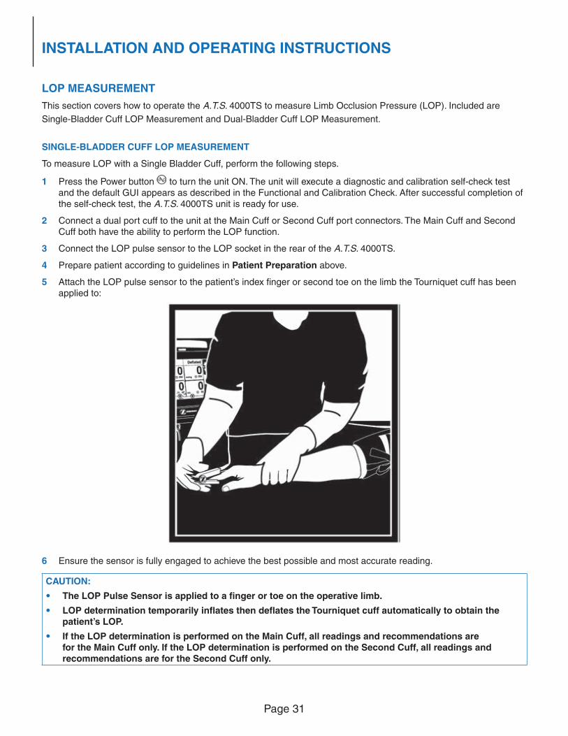
5 Attach the LOP pulse sensor to the patient’s index fi nger or second toe on the limb the Tourniquet cuff has been applied to:
6 Ensure the sensor is fully engaged to achieve the best possible and most accurate reading.
CAUTION:
• The LOP Pulse Sensor is applied to a fi nger or toe on the operative limb.
• LOP determination temporarily infl ates then defl ates the Tourniquet cuff automatically to obtain the patient’s LOP.
• If the LOP determination is performed on the Main Cuff, all readings and recommendations are for the Main Cuff only. If the LOP determination is performed on the Second Cuff, all readings and recommendations are for the Second Cuff only.
Page 32
INSTALLATION AND OPERATING INSTRUCTIONS
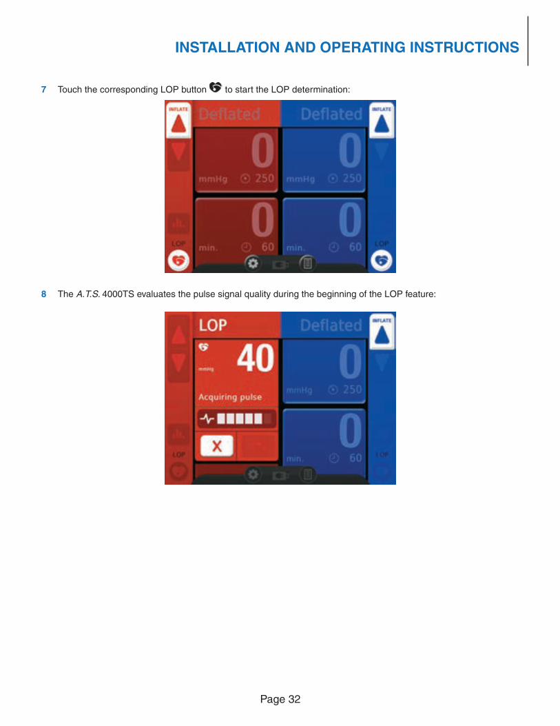
7 Touch the corresponding LOP button to start the LOP determination:
8 The A.T.S. 4000TS evaluates the pulse signal quality during the beginning of the LOP feature:
Page 33
INSTALLATION AND OPERATING INSTRUCTIONS
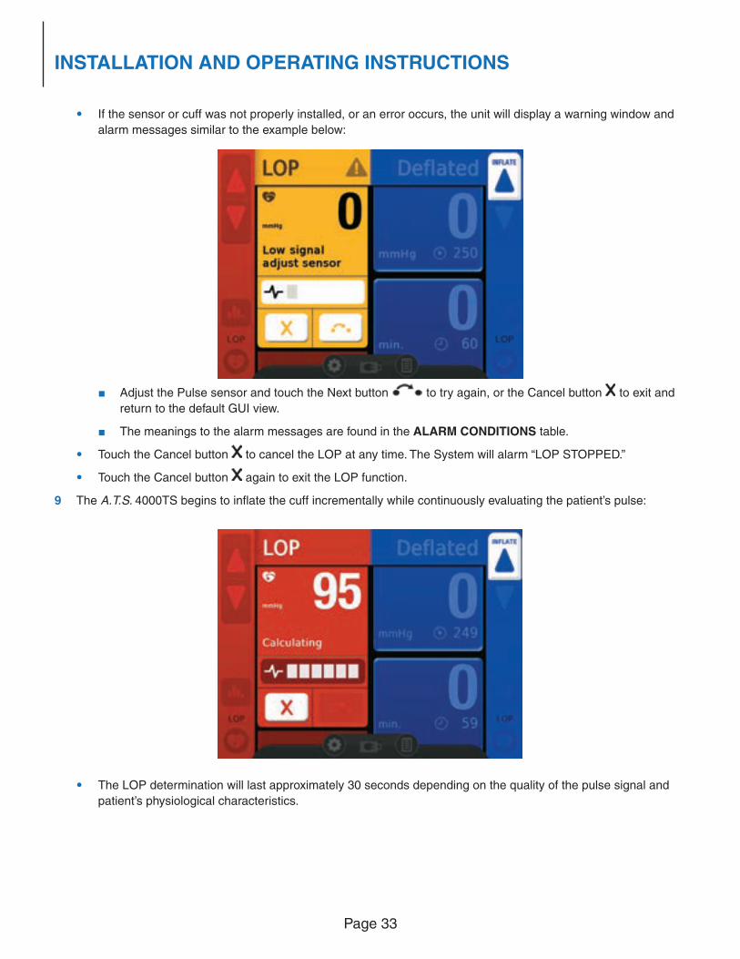
• If the sensor or cuff was not properly installed, or an error occurs, the unit will display a warning window and
alarm messages similar to the example below:
■ Adjust the Pulse sensor and touch the Next button to try again, or the Cancel button to exit and
return to the default GUI view.
■ The meanings to the alarm messages are found in the ALARM CONDITIONS table.
• Touch the Cancel button to cancel the LOP at any time. The System will alarm “LOP STOPPED.”
• Touch the Cancel button again to exit the LOP function.
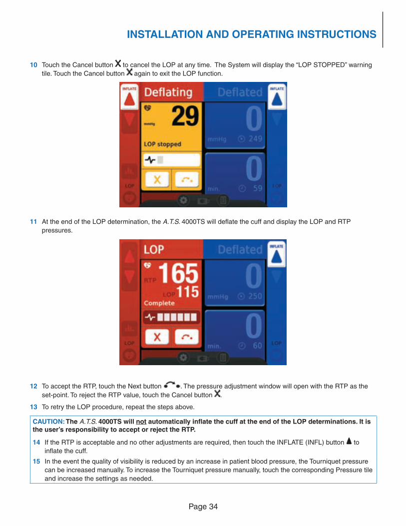
9 The A.T.S. 4000TS begins to infl ate the cuff incrementally while continuously evaluating the patient’s pulse:
• The LOP determination will last approximately 30 seconds depending on the quality of the pulse signal and
patient’s physiological characteristics.
Page 34
INSTALLATION AND OPERATING INSTRUCTIONS
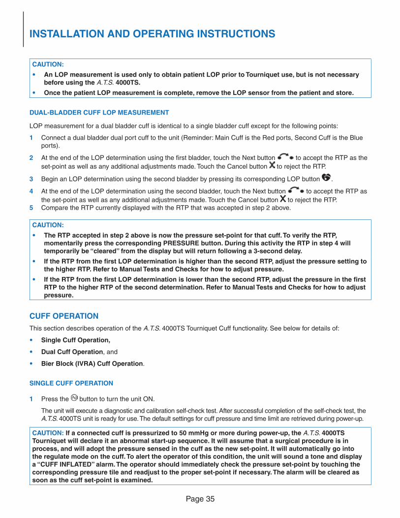
10 Touch the Cancel button to cancel the LOP at any time. The System will display the “LOP STOPPED” warning
tile. Touch the Cancel button again to exit the LOP function.
11 At the end of the LOP determination, the A.T.S. 4000TS will defl ate the cuff and display the LOP and RTP
pressures.
12 To accept the RTP, touch the Next button . The pressure adjustment window will open with the RTP as the
set-point. To reject the RTP value, touch the Cancel button .
13 To retry the LOP procedure, repeat the steps above.
CAUTION: The A.T.S. 4000TS will not automatically infl ate the cuff at the end of the LOP determinations. It is the user’s responsibility to accept or reject the RTP.
14 If the RTP is acceptable and no other adjustments are required, then touch the INFLATE (INFL) button to
infl ate the cuff.
15 In the event the quality of visibility is reduced by an increase in patient blood pressure, the Tourniquet pressure
can be increased manually. To increase the Tourniquet pressure manually, touch the corresponding Pressure tile
and increase the settings as needed.
Page 35
INSTALLATION AND OPERATING INSTRUCTIONS
CAUTION:
• An LOP measurement is used only to obtain patient LOP prior to Tourniquet use, but is not necessary before using the A.T.S. 4000TS.
• Once the patient LOP measurement is complete, remove the LOP sensor from the patient and store.
DUAL-BLADDER CUFF LOP MEASUREMENT
LOP measurement for a dual bladder cuff is identical to a single bladder cuff except for the following points:
1 Connect a dual bladder dual port cuff to the unit (Reminder: Main Cuff is the Red ports, Second Cuff is the Blue ports).
2 At the end of the LOP determination using the fi rst bladder, touch the Next button to accept the RTP as the
set-point as well as any additional adjustments made. Touch the Cancel button to reject the RTP.
3 Begin an LOP determination using the second bladder by pressing its corresponding LOP button .
4 At the end of the LOP determination using the second bladder, touch the Next button to accept the RTP as
the set-point as well as any additional adjustments made. Touch the Cancel button to reject the RTP.5 Compare the RTP currently displayed with the RTP that was accepted in step 2 above.
CAUTION:
• The RTP accepted in step 2 above is now the pressure set-point for that cuff. To verify the RTP, momentarily press the corresponding PRESSURE button. During this activity the RTP in step 4 will temporarily be “cleared” from the display but will return following a 3-second delay.
• If the RTP from the fi rst LOP determination is higher than the second RTP, adjust the pressure setting to the higher RTP. Refer to Manual Tests and Checks for how to adjust pressure.
• If the RTP from the fi rst LOP determination is lower than the second RTP, adjust the pressure in the fi rst RTP to the higher RTP of the second determination. Refer to Manual Tests and Checks for how to adjust pressure.
CUFF OPERATION
This section describes operation of the A.T.S. 4000TS Tourniquet Cuff functionality. See below for details of:
• Single Cuff Operation,
• Dual Cuff Operation, and
• Bier Block (IVRA) Cuff Operation.
SINGLE CUFF OPERATION
1 Press the button to turn the unit ON.
The unit will execute a diagnostic and calibration self-check test. After successful completion of the self-check test, the A.T.S. 4000TS unit is ready for use. The default settings for cuff pressure and time limit are retrieved during power-up.
CAUTION: If a connected cuff is pressurized to 50 mmHg or more during power-up, the A.T.S. 4000TS Tourniquet will declare it an abnormal start-up sequence. It will assume that a surgical procedure is in process, and will adopt the pressure sensed in the cuff as the new set-point. It will automatically go into the regulate mode on the cuff. To alert the operator of this condition, the unit will sound a tone and display a “CUFF INFLATED” alarm. The operator should immediately check the pressure set-point by touching the corresponding pressure tile and readjust to the proper set-point if necessary. The alarm will be cleared as soon as the cuff set-point is examined.
Page 36
INSTALLATION AND OPERATING INSTRUCTIONS
2 Prepare patient according to guidelines in Patient Preparation above.
3 Establish the viability of the skin and deeper tissues prior to exsanguination of the limb and Tourniquet infl ation.
4 The surgeon determines Tourniquet use-parameters as discussed above in Surgeon Decisions.
5 Exsanguinate the limb.
• Elevate the limb for a minimum of 2 minutes.
• Wrap the limb from distal to proximal with an Esmarch, Martin, or elastic exsanguinating bandage.
6 Apply a leak-free dual-port Tourniquet cuff smoothly without wrinkles.
• Apply a Zimmer protective sleeve or other padding to the limb.
• Position the Tourniquet cuff so that its distal edge is located approximately 1 in. (2.5 cm) from the proximal edge of the exsanguinating bandage.
• Place the valve port and hose connections so that the hose will not be kinked when the limb is positioned for surgery.
7 Connect the dual port cuff hoses to the unit at the Main Cuff connectors (Red ports).
8 Set target PRESSURE and TIME set-points.
Refer to PRESSURE and TIME set-point system tests under the Manual Tests and Checks section for how to set target PRESSURE and TIME set-points.
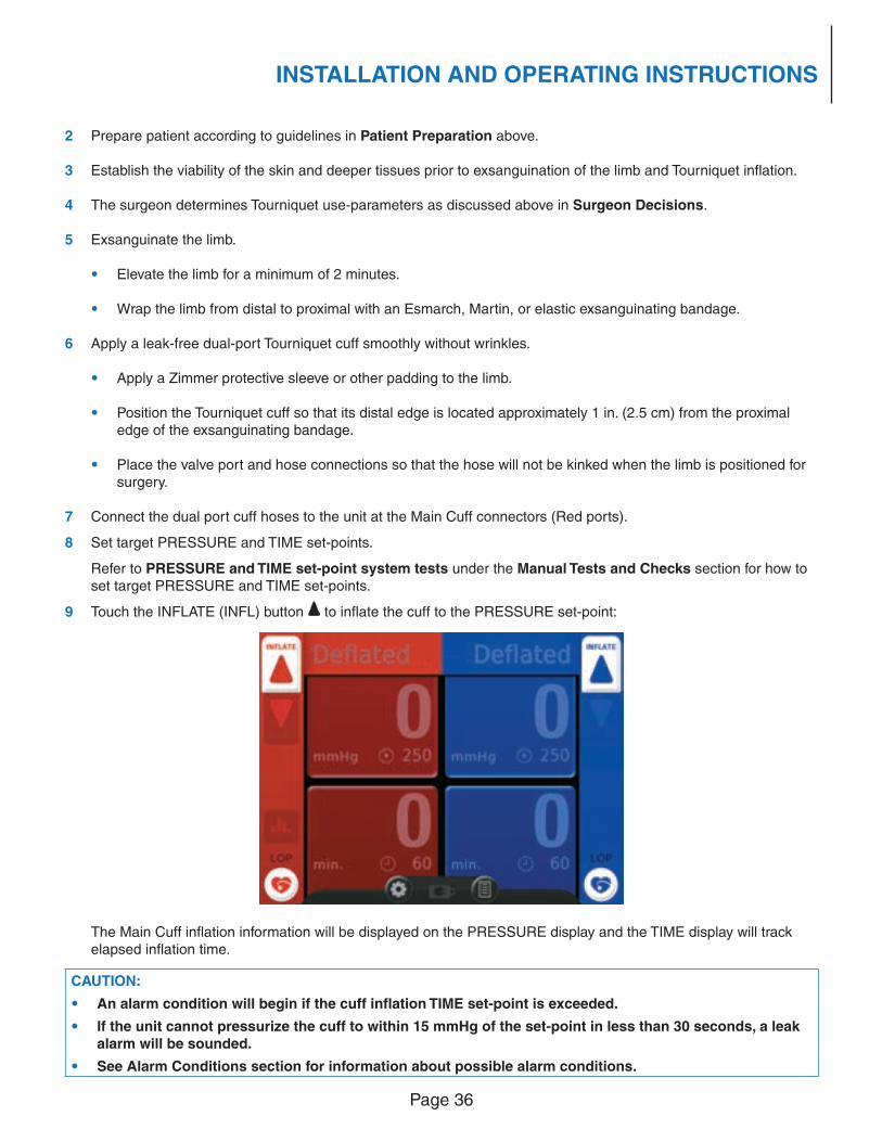
9 Touch the INFLATE (INFL) button to infl ate the cuff to the PRESSURE set-point:
The Main Cuff infl ation information will be displayed on the PRESSURE display and the TIME display will track elapsed infl ation time.
CAUTION:
• An alarm condition will begin if the cuff infl ation TIME set-point is exceeded.
• If the unit cannot pressurize the cuff to within 15 mmHg of the set-point in less than 30 seconds, a leak alarm will be sounded.
• See Alarm Conditions section for information about possible alarm conditions.
Page 37
INSTALLATION AND OPERATING INSTRUCTIONS
10 Remove the exsanguinating bandage.
11 Administer the anesthetic agent or nerve block if regional anesthesia is being used.
12 Perform the surgical procedure.
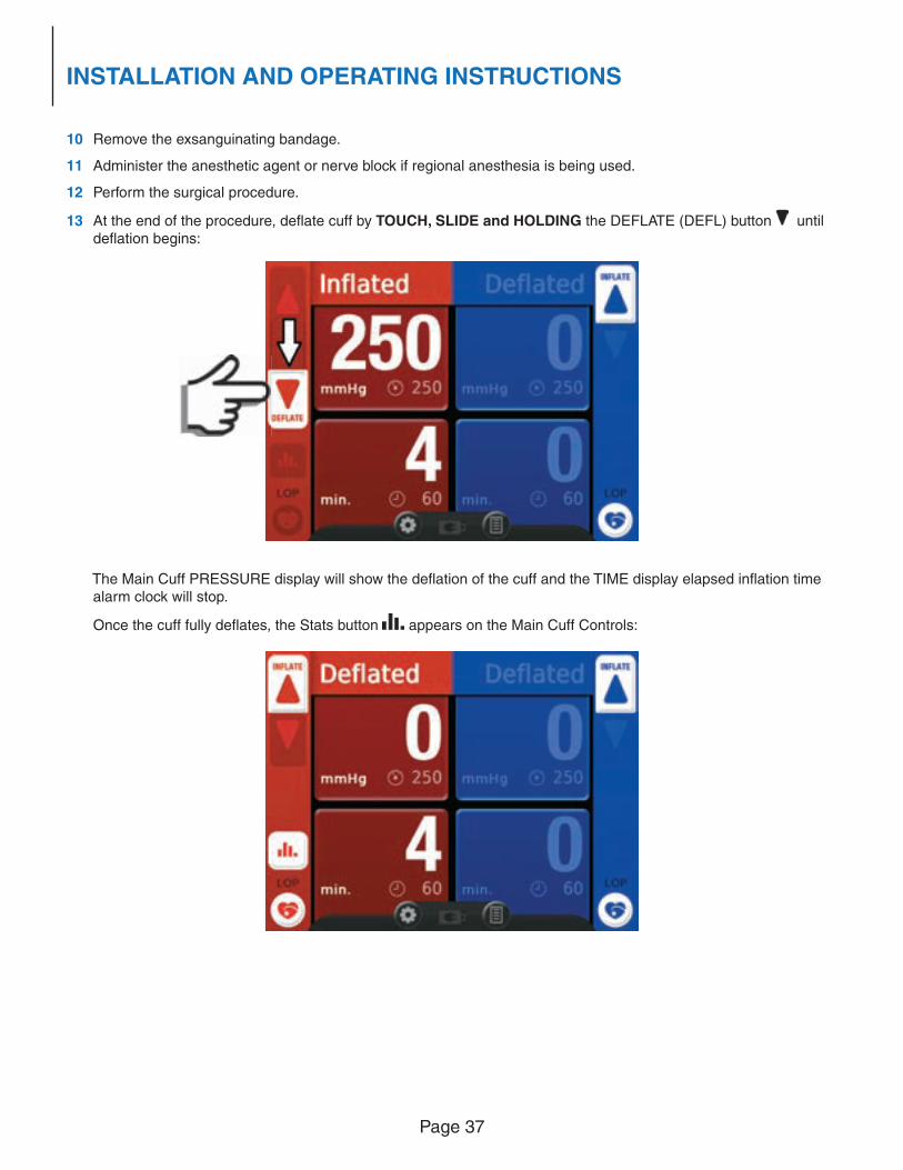
13 At the end of the procedure, defl ate cuff by TOUCH, SLIDE and HOLDING the DEFLATE (DEFL) button until defl ation begins:
The Main Cuff PRESSURE display will show the defl ation of the cuff and the TIME display elapsed infl ation time alarm clock will stop.
Once the cuff fully defl ates, the Stats button appears on the Main Cuff Controls:
Page 38
INSTALLATION AND OPERATING INSTRUCTIONS
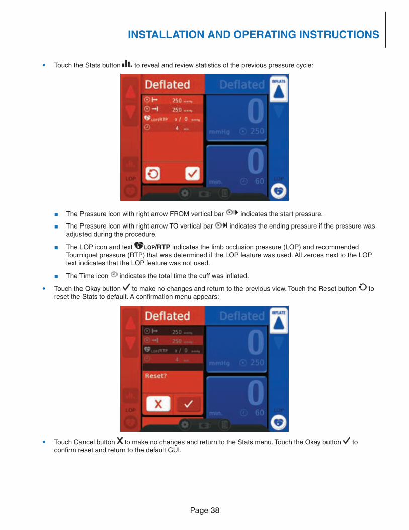
• Touch the Stats button to reveal and review statistics of the previous pressure cycle:
■ The Pressure icon with right arrow FROM vertical bar indicates the start pressure.
■ The Pressure icon with right arrow TO vertical bar indicates the ending pressure if the pressure was adjusted during the procedure.
■ The LOP icon and text LOP/RTP indicates the limb occlusion pressure (LOP) and recommended Tourniquet pressure (RTP) that was determined if the LOP feature was used. All zeroes next to the LOP text indicates that the LOP feature was not used.
■ The Time icon indicates the total time the cuff was infl ated.
• Touch the Okay button to make no changes and return to the previous view. Touch the Reset button to reset the Stats to default. A confi rmation menu appears:
• Touch Cancel button to make no changes and return to the Stats menu. Touch the Okay button to confi rm reset and return to the default GUI.
Page 39
INSTALLATION AND OPERATING INSTRUCTIONS
CAUTION:
• If Advanced Leak Detection detected a cuff leak during the infl ation period, the system will indicate “LEAK DETECTED.”
• Resetting the Stats also resets the cuff timer.
• After approximately 5 seconds of inactivity the system will automatically close open menus and return to its normal mode of operation.
14 Remove the Tourniquet cuff and any underlying bandages or protective sleeve immediately following fi nal defl ation.
15 Note the time of Tourniquet cuff removal, if desired.
16 Check the circulation of the affected limb.
17 Disconnect the cuff from the A.T.S. 4000TS unit.
18 If desired, touch the Power button to set the A.T.S. 4000TS unit to STANDBY.
CAUTION:
• The elapsed infl ation time can be “zeroed” after the cuff has been defl ated in the Time tile or by resetting the Stats.
• During normal use, the A.T.S. 4000TS should not be set to STANDBY if pressure is present in either cuff. Once the cuff has been properly defl ated, removed from the patient, and disconnected from the A.T.S. 4000TS, the unit can be set to STANDBY.
DUAL CUFF OPERATION
Operation of the unit is identical to Single Cuff Operation above, except for the following points:
• Two dual port cuffs are connected to the unit (Reminder: Main Cuff is the Red ports, Second Cuff is the Blue ports).
• The Main and Second Pressure and Time tiles will display infl ation information and begin timing the cuff infl ation.
• Defl ation of one cuff will not be permitted while the other cuff is infl ating.
• When infl ating a second cuff with the other cuff already infl ated, the unit will continuously check the original cuff to ensure that the pressure is within allowable limits. The unit will stop its infl ation and maintain the original cuff to within 10 mmHg of the set-point before returning to the infl ating cuff. This ensures that at least one cuff maintains occlusion at all times. If there is a signifi cant leak in the original cuff, this feature could cause the infl ation rate of the subsequent cuff to be longer and perhaps even cause the 30-second infl ation alarm to sound.
When both cuffs are infl ated, the PRESSURE and TIME tiles display independent information for each cuff. That is, the PRESSURE and TIME tiles are independently operated and controlled for each cuff.
CAUTION:
In order to defl ate the fi nal cuff, a sequence must be followed to prevent accidental defl ation:
• TOUCH, SLIDE and HOLD the DEFLATE (DEFL) button on the fi nal cuff.
• The opposite cuff will alarm “CUFF DEFLATED” to indicate the fi rst cuff is defl ated.
• A pop-up window will appear on the fi nal cuff’s display area asking for defl ation confi rmation. Touch the
Cancel button to cancel the defl ation or the Okay button to confi rm the defl ation.
• The cuff will defl ate.
• This safety feature is particularly useful when using the unit for Bier Block Cuff Operation, (IVRA).
Page 40
INSTALLATION AND OPERATING INSTRUCTIONS
BIER BLOCK (IVRA) CUFF OPERATION
Review SINGLE CUFF OPERATION and DUAL CUFF OPERATION.
The following are suggested cuff connections:
• The proximal cuff connected to the Red Main Cuff ports using the white/red cuff tubing;
• The distal cuff connected to the Blue Second Cuff ports using the white/blue cuff tubing.
Follow the cuff infl ation sequence adopted by your institution or requested by the surgeon.
When requested, defl ate the fi rst cuff by TOUCH, SLIDE and HOLDING the DEFLATE (DEFL) button until the cuff defl ates.
CAUTION:
In order to defl ate the fi nal cuff, a sequence must be followed to prevent accidental defl ation:
• TOUCH, SLIDE and HOLD the DEFLATE (DEFL) button on the fi nal cuff.
• The opposite cuff will alarm “CUFF DEFLATED” to indicate the fi rst cuff is defl ated.
• A pop-up window will appear on the fi nal cuff’s display area asking for defl ation confi rmation. Touch the
Cancel button to cancel the defl ation or the Okay button to confi rm the defl ation.
• The cuff will defl ate.
CAUTION:
• Defl ation of a cuff is not possible while the other is infl ating.
• For Bier Block procedures follow the cuff infl ation/ defl ation sequence adopted by your institution or requested by the surgeon.
ALARM CONDITIONS
There are a number of conditions for which the A.T.S. 4000TS Tourniquet will produce a visual and/or audible alarm. The appropriate actions indicated are based on the most probable causes and should only be used as a guide. Other causes of alarm conditions may indicate a need for other actions.
Most audible alarm tones (non-technical failures) may be silenced for 30 seconds by pressing the ALARM SILENCE button. The tone will be re-enabled at the end of the silenced period. Pressing the ALARM SILENCE button will cause the alarm tone to be silenced again.
To minimize nuisance alarms that can be caused by range-of-motion movement of the patient’s limbs, a 1.5-second delay has been designed into the alarm actuation.
The alarm conditions, indications, and appropriate actions are shown in the ALARM CONDITIONS table. In addition to the alarm conditions shown, it is conceivable that a technical failure could occur for which the indications are unintelligible and unpredictable. In this situation, the A.T.S. 4000TS is designed to close the valves, causing the system to hold cuff pressure and alarm a constant tone. The A.T.S. 4000TS Tourniquet will also provide Error Code information for technical failure alarms as shown in the ERROR CODES table.
Under certain conditions, such as “SYSTEM FAILURE DETECTED” appears or the information that appears on the screen is unintelligible, the operator should conclude that a technical failure has occurred, rendering the unit unusable. The appropriate action is to set the unit to STANDBY by pressing the ON/ STANDBY button. Since this removes power from the internal instrument circuitry, all instrument functions, commands to the valves and pump will cease. This will cause the cuff to hold pressure (in the absence of leaks). Clamp the cuff lines with hemostats and replace the Tourniquet unit.
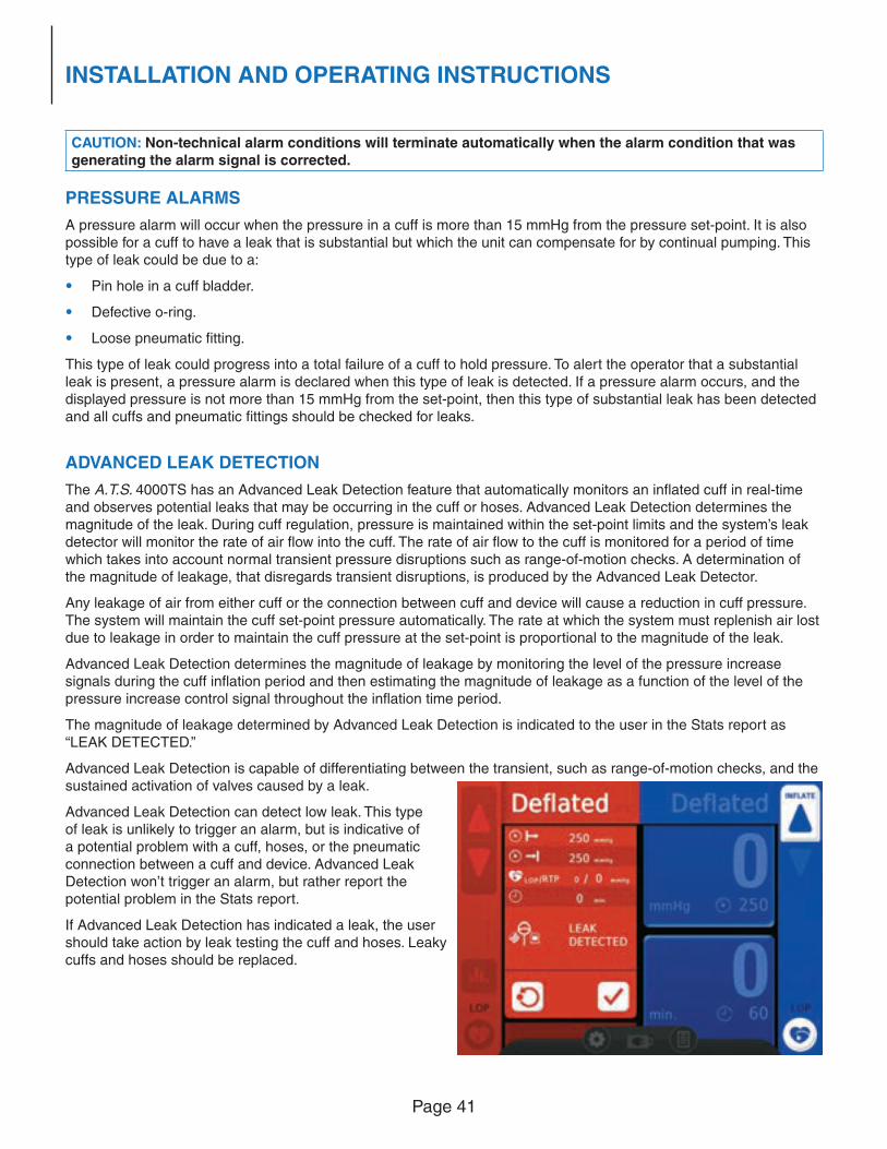
Page 41
INSTALLATION AND OPERATING INSTRUCTIONS
CAUTION: Non-technical alarm conditions will terminate automatically when the alarm condition that was generating the alarm signal is corrected.
PRESSURE ALARMS
A pressure alarm will occur when the pressure in a cuff is more than 15 mmHg from the pressure set-point. It is also possible for a cuff to have a leak that is substantial but which the unit can compensate for by continual pumping. This type of leak could be due to a:
• Pin hole in a cuff bladder.
• Defective o-ring.
• Loose pneumatic fi tting.
This type of leak could progress into a total failure of a cuff to hold pressure. To alert the operator that a substantial leak is present, a pressure alarm is declared when this type of leak is detected. If a pressure alarm occurs, and the displayed pressure is not more than 15 mmHg from the set-point, then this type of substantial leak has been detected and all cuffs and pneumatic fi ttings should be checked for leaks.
ADVANCED LEAK DETECTION
The A.T.S. 4000TS has an Advanced Leak Detection feature that automatically monitors an infl ated cuff in real-time and observes potential leaks that may be occurring in the cuff or hoses. Advanced Leak Detection determines the magnitude of the leak. During cuff regulation, pressure is maintained within the set-point limits and the system’s leak detector will monitor the rate of air fl ow into the cuff. The rate of air fl ow to the cuff is monitored for a period of time which takes into account normal transient pressure disruptions such as range-of-motion checks. A determination of the magnitude of leakage, that disregards transient disruptions, is produced by the Advanced Leak Detector.
Any leakage of air from either cuff or the connection between cuff and device will cause a reduction in cuff pressure. The system will maintain the cuff set-point pressure automatically. The rate at which the system must replenish air lost due to leakage in order to maintain the cuff pressure at the set-point is proportional to the magnitude of the leak.
Advanced Leak Detection determines the magnitude of leakage by monitoring the level of the pressure increase signals during the cuff infl ation period and then estimating the magnitude of leakage as a function of the level of the pressure increase control signal throughout the infl ation time period.
The magnitude of leakage determined by Advanced Leak Detection is indicated to the user in the Stats report as
“LEAK DETECTED.”
Advanced Leak Detection is capable of differentiating between the transient, such as range-of-motion checks, and the sustained activation of valves caused by a leak.
Advanced Leak Detection can detect low leak. This type of leak is unlikely to trigger an alarm, but is indicative of a potential problem with a cuff, hoses, or the pneumatic connection between a cuff and device. Advanced Leak Detection won’t trigger an alarm, but rather report the potential problem in the Stats report.
If Advanced Leak Detection has indicated a leak, the user should take action by leak testing the cuff and hoses. Leaky cuffs and hoses should be replaced.
Page 42
INSTALLATION AND OPERATING INSTRUCTIONS
ALARM/WARNING COLORS AND AUDIBLE TONES
During the course of operation, the A.T.S. 4000TS may display a fl ashing red or yellow light and yellow warning tiles containing Alarm Condition messages. For a technical failure, it will also display warning messages accompanied by Error Codes and a yellow exclamation point graphic.
VISUAL AND AUDITORY ALARM PRIORITY
Visual Indicator Light
Auditory Priority Tone
AuditoryPulse Pattern
Comments
Constant Red Technical Constant tone Constant tone indicating technical failure.
Flashing Red High 10 tone pulses per burst, each repeating two identical groups
of 5 tone pulses with a pause
between each group.
Indicates immediate operator response is required. Fastest auditory indicator tone pulse at less than half the duration of
Medium priority.
Flashing Yellow Medium 3 tone pulses per burst. Indicates prompt operator response is required. Baseline auditory
indicator tone pulse speed.
Constant Yellow Low 1 tone pulse per burst. Indicates operator awareness is required. The auditory indicator
tone pulse is slower than either Medium or High priority.
ALARM CONDITION AND ERROR CODE TABLES
Alarm Conditions are accompanied by a warning message and sometimes Error Codes along with an Indicator Light and audible Priority Tone as detailed in the ALARM CONDITIONS table. Most warning messages during operation appear as yellow tiles. LOP related alarms are grouped at the end of the table. Error Codes are detailed in the ERROR CODES table.
ALARM CONDITIONS
Warning
Message
Indicator
Light
Priority
Tone
Condition, Remarks and Appropriate Action
HIGH PRESSURE Flashing
Red
High Condition: High Pressure.
Cuff pressure is at least 15 mmHg above set-point. May be caused by transient
conditions such as patient movement, controller overshoot, or hose occlusion. Check
all lines and connections. If this condition persists without apparent cause, the A.T.S. 4000TS unit may need servicing.
LOW PRESSURE FlashingRed
High Condition: Low Pressure.
Cuff pressure is at least 15 mmHg below set-point. May be caused by a leak in the system, or a hose occlusion. Check all lines and connections.
RESERVOIR LEAK
Flashing
Yellow
Medium Condition: Reservoir leaking.
A leak is present between the pressure pump and cuff valves. Do not use the unit.
Service the unit.
TIMER FlashingYellow
Medium Condition: Timer alarm.
Cuff infl ation time set-point has been reached. The Surgeon should be warned of the time up condition. Only on the direction of the surgeon should time be set to a new
value.
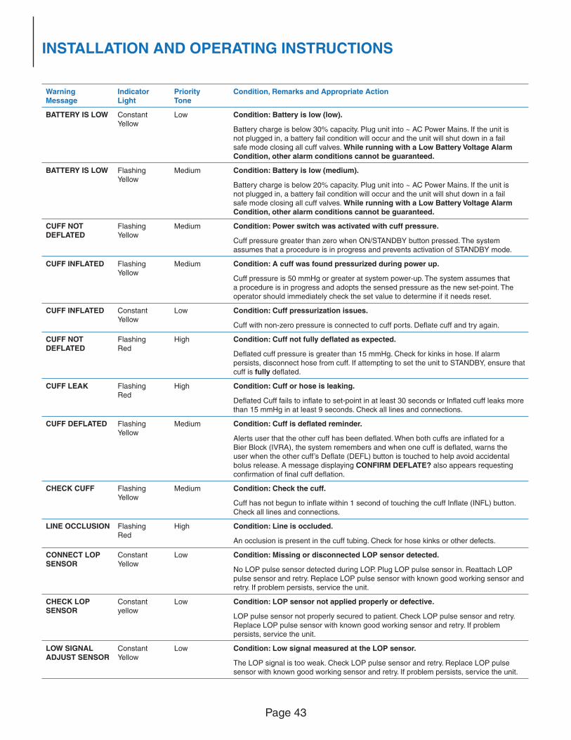
Page 43
INSTALLATION AND OPERATING INSTRUCTIONS
WarningMessage
IndicatorLight
PriorityTone
Condition, Remarks and Appropriate Action
BATTERY IS LOW Constant Yellow
Low Condition: Battery is low (low).
Battery charge is below 30% capacity. Plug unit into ~ AC Power Mains. If the unit is not plugged in, a battery fail condition will occur and the unit will shut down in a fail safe mode closing all cuff valves. While running with a Low Battery Voltage Alarm Condition, other alarm conditions cannot be guaranteed.
BATTERY IS LOW FlashingYellow
Medium Condition: Battery is low (medium).
Battery charge is below 20% capacity. Plug unit into ~ AC Power Mains. If the unit is not plugged in, a battery fail condition will occur and the unit will shut down in a fail safe mode closing all cuff valves. While running with a Low Battery Voltage Alarm Condition, other alarm conditions cannot be guaranteed.
CUFF NOT DEFLATED
FlashingYellow
Medium Condition: Power switch was activated with cuff pressure.
Cuff pressure greater than zero when ON/STANDBY button pressed. The system assumes that a procedure is in progress and prevents activation of STANDBY mode.
CUFF INFLATED FlashingYellow
Medium Condition: A cuff was found pressurized during power up.
Cuff pressure is 50 mmHg or greater at system power-up. The system assumes that a procedure is in progress and adopts the sensed pressure as the new set-point. The
operator should immediately check the set value to determine if it needs reset.
CUFF INFLATED Constant
Yellow
Low Condition: Cuff pressurization issues.
Cuff with non-zero pressure is connected to cuff ports. Defl ate cuff and try again.
CUFF NOT
DEFLATEDFlashing
Red
High Condition: Cuff not fully defl ated as expected.
Defl ated cuff pressure is greater than 15 mmHg. Check for kinks in hose. If alarm
persists, disconnect hose from cuff. If attempting to set the unit to STANDBY, ensure that
cuff is fully defl ated.
CUFF LEAK Flashing
Red
High Condition: Cuff or hose is leaking.
Defl ated Cuff fails to infl ate to set-point in at least 30 seconds or Infl ated cuff leaks more
than 15 mmHg in at least 9 seconds. Check all lines and connections.
CUFF DEFLATED Flashing
Yellow
Medium Condition: Cuff is defl ated reminder.
Alerts user that the other cuff has been defl ated. When both cuffs are infl ated for a
Bier Block (IVRA), the system remembers and when one cuff is defl ated, warns the
user when the other cuff’s Defl ate (DEFL) button is touched to help avoid accidental
bolus release. A message displaying CONFIRM DEFLATE? also appears requesting
confi rmation of fi nal cuff defl ation.
CHECK CUFF Flashing
Yellow
Medium Condition: Check the cuff.
Cuff has not begun to infl ate within 1 second of touching the cuff Infl ate (INFL) button.
Check all lines and connections.
LINE OCCLUSION FlashingRed
High Condition: Line is occluded.
An occlusion is present in the cuff tubing. Check for hose kinks or other defects.
CONNECT LOP
SENSORConstant Yellow
Low Condition: Missing or disconnected LOP sensor detected.
No LOP pulse sensor detected during LOP. Plug LOP pulse sensor in. Reattach LOP
pulse sensor and retry. Replace LOP pulse sensor with known good working sensor and retry. If problem persists, service the unit.
CHECK LOP SENSOR
Constant yellow
Low Condition: LOP sensor not applied properly or defective.
LOP pulse sensor not properly secured to patient. Check LOP pulse sensor and retry. Replace LOP pulse sensor with known good working sensor and retry. If problem
persists, service the unit.
LOW SIGNAL
ADJUST SENSORConstant Yellow
Low Condition: Low signal measured at the LOP sensor.
The LOP signal is too weak. Check LOP pulse sensor and retry. Replace LOP pulse sensor with known good working sensor and retry. If problem persists, service the unit.
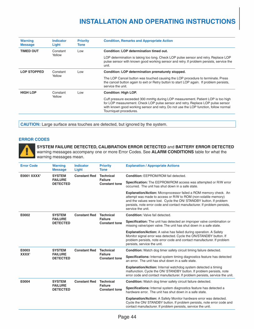
Page 44
INSTALLATION AND OPERATING INSTRUCTIONS
WarningMessage
IndicatorLight
PriorityTone
Condition, Remarks and Appropriate Action
TIMED OUT Constant Yellow
Low Condition: LOP determination timed out.
LOP determination is taking too long. Check LOP pulse sensor and retry. Replace LOP pulse sensor with known good working sensor and retry. If problem persists, service the unit.
LOP STOPPED Constant Yellow
Low Condition: LOP determination prematurely stopped.
The LOP Cancel button was touched causing the LOP procedure to terminate. Press the cancel button again to exit or Retry button to start LOP again. If problem persists, service the unit.
HIGH LOP Constant Yellow
Low Condition: High LOP.
Cuff pressure exceeded 300 mmHg during LOP measurement. Patient LOP is too high for LOP measurement. Check LOP pulse sensor and retry. Replace LOP pulse sensor with known good working sensor and retry. Do not use the LOP function, follow normal Tourniquet procedures.
CAUTION: Large surface area touches are detected, but ignored by the system.
ERROR CODES
SYSTEM FAILURE DETECTED, CALIBRATION ERROR DETECTED and BATTERY ERROR DETECTED warning messages accompany one or more Error Codes. See ALARM CONDITIONS table for what the warning messages mean.
Error Code Warning
Message
Indicator
Light
Priority
Tone
Explanation / Appropriate Actions
E0001 XXXX1 SYSTEM
FAILURE
DETECTED
Constant Red Technical
Failure
Constant tone
Condition: EEPROM/ROM fail detected.
Specifi cation: The EEPROM/ROM access was attempted or R/W error
occurred. The unit has shut down in a safe state.
Explanation/Action: Microprocessor failed a ROM memory check. An
attempt was made to access or R/W to ROM (non-volatile memory)
and the values were lost. Cycle the ON/ STANDBY button. If problem
persists, note error code and contact manufacturer. If problem persists,
service the unit.
E0002 SYSTEM FAILURE
DETECTED
Constant Red TechnicalFailure
Constant tone
Condition: Valve fail detected.
Specifi cation: The unit has detected an improper valve combination or missing valve/open valve. The unit has shut down in a safe state.
Explanation/Action: A valve has failed during operation. A Safety
Monitor signal error was detected. Cycle the ON/STANDBY button. If problem persists, note error code and contact manufacturer. If problem persists, service the unit.
E0003XXXX1
SYSTEM FAILURE
DETECTED
Constant Red Technical
FailureConstant tone
Condition: Watch dog timer safety circuit timing failure detected.
Specifi cations: Internal system timing diagnostics feature has detected
an error. The unit has shut down in a safe state.
Explanation/Action: Internal watchdog system detected a timing malfunction. Cycle the ON/ STANDBY button. If problem persists, note
error code and contact manufacturer. If problem persists, service the unit.
E0004 SYSTEM
FAILURE
DETECTED
Constant Red TechnicalFailure
Constant tone
Condition: Watch dog timer safety circuit failure detected.
Specifi cations: Internal system diagnostics feature has detected a hardware error. The unit has shut down in a safe state.
Explanation/Action: A Safety Monitor hardware error was detected. Cycle the ON/ STANDBY button. If problem persists, note error code and contact manufacturer. If problem persists, service the unit.
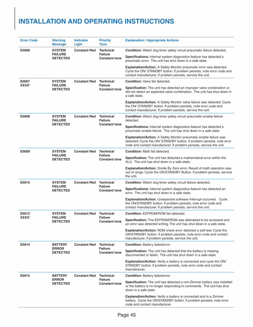
Page 45
INSTALLATION AND OPERATING INSTRUCTIONS
Error Code WarningMessage
IndicatorLight
PriorityTone
Explanation / Appropriate Actions
E0006 SYSTEM FAILURE DETECTED
Constant Red TechnicalFailureConstant tone
Condition: Watch dog timer safety circuit pneumatic failure detected.
Specifi cations: Internal system diagnostics feature has detected a pneumatic error. The unit has shut down in a safe state.
Explanation/Action: A Safety Monitor pneumatic error was detected. Cycle the ON/ STANDBY button. If problem persists, note error code and contact manufacturer. If problem persists, service the unit.
E0007XXXX1
SYSTEM FAILURE DETECTED
Constant Red TechnicalFailureConstant tone
Condition: Valve fail detected.
Specifi cation: The unit has detected an improper valve combination or did not detect an expected valve combination. The unit has shut down in a safe state.
Explanation/Action: A Safety Monitor valve failure was detected. Cycle the ON/ STANDBY button. If problem persists, note error code and contact manufacturer. If problem persists, service the unit.
E0008 SYSTEM FAILURE DETECTED
Constant Red TechnicalFailureConstant tone
Condition: Watch dog timer safety circuit pneumatic enable failure detected.
Specifi cations: Internal system diagnostics feature has detected a
pneumatic enable failure. The unit has shut down in a safe state.
Explanation/Action: A Safety Monitor pneumatic enable failure was
detected. Cycle the ON/ STANDBY button. If problem persists, note error
code and contact manufacturer. If problem persists, service the unit.
E0009 SYSTEM
FAILURE
DETECTED
Constant Red Technical
Failure
Constant tone
Condition: Math fail detected.
Specifi cation: The unit has detected a mathematical error within the
ALU. The unit has shut down in a safe state.
Explanation/Action: Divide By Zero error. Result of math operation was
out of range. Cycle the ON/STANDBY Button. If problem persists, service
the unit.
E0010 SYSTEM
FAILURE
DETECTED
Constant Red Technical
Failure
Constant tone
Condition: Watch dog timer safety circuit failure detected.
Specifi cations: Internal system diagnostics feature has detected an
error. The unit has shut down in a safe state.
Explanation/Action: Unexpected software Interrupt occurred. Cycle
the ON/STANDBY button. If problem persists, note error code and
contact manufacturer. If problem persists, service the unit.
E0012
XXXX1
SYSTEM
FAILURE
DETECTED
Constant Red Technical
Failure
Constant tone
Condition: EEPROM/ROM fail detected.
Specifi cation: The EEPROM/ROM was attempted to be accessed and
an error was detected writing. The unit has shut down in a safe state.
Explanation/Action: ROM check error detected a self-test. Cycle the ON/STANDBY button. If problem persists, note error code and contact manufacturer. If problem persists, service the unit.
E0014 BATTERY ERROR
DETECTED
Constant Red Technical
FailureConstant tone
Condition: Battery failed/error.
Specifi cation: The unit has detected that the battery is missing,
disconnected or failed. The unit has shut down in a safe state.
Explanation/Action: Verify a battery is connected and cycle the ON/
STANDBY button. If problem persists, note error code and contact manufacturer.
E0015 BATTERY ERROR
DETECTED
Constant Red TechnicalFailure
Constant tone
Condition: Battery failed/error.
Specifi cation: The unit has detected a non-Zimmer battery was installed or the battery is no longer responding to commands. The unit has shut
down in a safe state.
Explanation/Action: Verify a battery is connected and is a Zimmer
battery. Cycle the ON/STANDBY button. If problem persists, note error code and contact manufacturer.
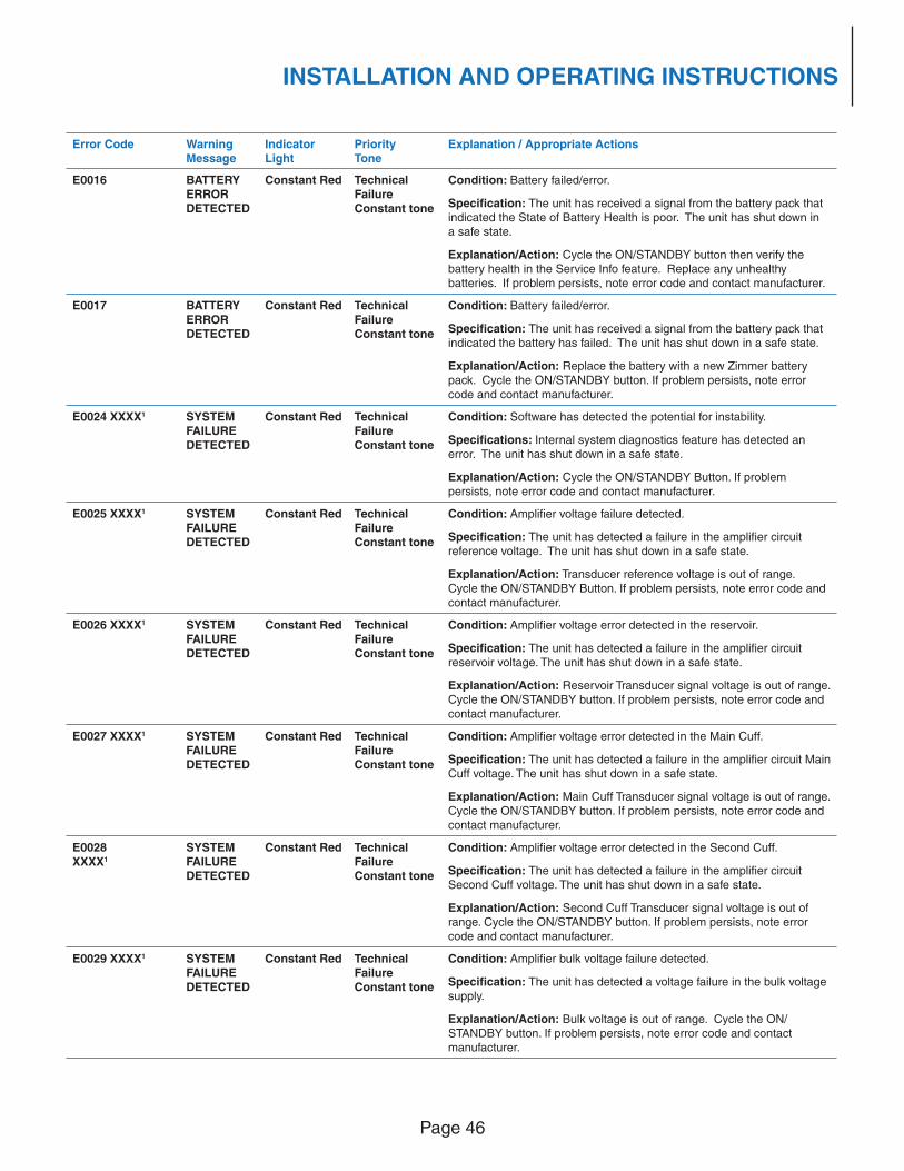
Page 46
INSTALLATION AND OPERATING INSTRUCTIONS
Error Code WarningMessage
IndicatorLight
PriorityTone
Explanation / Appropriate Actions
E0016 BATTERY ERROR DETECTED
Constant Red TechnicalFailureConstant tone
Condition: Battery failed/error.
Specifi cation: The unit has received a signal from the battery pack that indicated the State of Battery Health is poor. The unit has shut down in a safe state.
Explanation/Action: Cycle the ON/STANDBY button then verify the battery health in the Service Info feature. Replace any unhealthy batteries. If problem persists, note error code and contact manufacturer.
E0017 BATTERY ERROR DETECTED
Constant Red TechnicalFailureConstant tone
Condition: Battery failed/error.
Specifi cation: The unit has received a signal from the battery pack that indicated the battery has failed. The unit has shut down in a safe state.
Explanation/Action: Replace the battery with a new Zimmer battery pack. Cycle the ON/STANDBY button. If problem persists, note error code and contact manufacturer.
E0024 XXXX1 SYSTEM FAILURE DETECTED
Constant Red TechnicalFailureConstant tone
Condition: Software has detected the potential for instability.
Specifi cations: Internal system diagnostics feature has detected an error. The unit has shut down in a safe state.
Explanation/Action: Cycle the ON/STANDBY Button. If problem
persists, note error code and contact manufacturer.
E0025 XXXX1 SYSTEM
FAILURE
DETECTED
Constant Red Technical
Failure
Constant tone
Condition: Amplifi er voltage failure detected.
Specifi cation: The unit has detected a failure in the amplifi er circuit
reference voltage. The unit has shut down in a safe state.
Explanation/Action: Transducer reference voltage is out of range.
Cycle the ON/STANDBY Button. If problem persists, note error code and
contact manufacturer.
E0026 XXXX1 SYSTEM
FAILURE
DETECTED
Constant Red Technical
Failure
Constant tone
Condition: Amplifi er voltage error detected in the reservoir.
Specifi cation: The unit has detected a failure in the amplifi er circuit
reservoir voltage. The unit has shut down in a safe state.
Explanation/Action: Reservoir Transducer signal voltage is out of range.
Cycle the ON/STANDBY button. If problem persists, note error code and
contact manufacturer.
E0027 XXXX1 SYSTEM
FAILURE
DETECTED
Constant Red Technical
Failure
Constant tone
Condition: Amplifi er voltage error detected in the Main Cuff.
Specifi cation: The unit has detected a failure in the amplifi er circuit Main Cuff voltage. The unit has shut down in a safe state.
Explanation/Action: Main Cuff Transducer signal voltage is out of range.
Cycle the ON/STANDBY button. If problem persists, note error code and contact manufacturer.
E0028XXXX1
SYSTEM FAILURE
DETECTED
Constant Red Technical
FailureConstant tone
Condition: Amplifi er voltage error detected in the Second Cuff.
Specifi cation: The unit has detected a failure in the amplifi er circuit
Second Cuff voltage. The unit has shut down in a safe state.
Explanation/Action: Second Cuff Transducer signal voltage is out of range. Cycle the ON/STANDBY button. If problem persists, note error
code and contact manufacturer.
E0029 XXXX1 SYSTEM FAILURE
DETECTED
Constant Red Technical
FailureConstant tone
Condition: Amplifi er bulk voltage failure detected.
Specifi cation: The unit has detected a voltage failure in the bulk voltage
supply.
Explanation/Action: Bulk voltage is out of range. Cycle the ON/
STANDBY button. If problem persists, note error code and contact manufacturer.
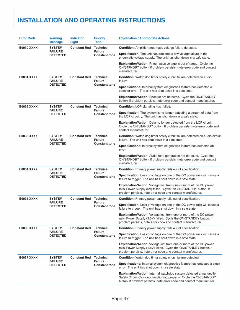
Page 47
INSTALLATION AND OPERATING INSTRUCTIONS
Error Code WarningMessage
IndicatorLight
PriorityTone
Explanation / Appropriate Actions
E0030 XXXX1 SYSTEM FAILURE DETECTED
Constant Red TechnicalFailureConstant tone
Condition: Amplifi er pneumatic voltage failure detected.
Specifi cation: The unit has detected a low voltage failure in the pneumatic voltage supply. The unit has shut down in a safe state.
Explanation/Action: Pneumatics voltage is out of range. Cycle the ON/STANDBY button. If problem persists, note error code and contact manufacturer.
E0031 XXXX1 SYSTEM FAILURE DETECTED
Constant Red TechnicalFailureConstant tone
Condition: Watch dog timer safety circuit failure detected an audio failure.
Specifi cations: Internal system diagnostics feature has detected a speaker error. The unit has shut down in a safe state.
Explanation/Action: Speaker not detected. Cycle the ON/STANDBY button. If problem persists, note error code and contact manufacturer.
E0032 XXXX1 SYSTEM FAILURE DETECTED
Constant Red TechnicalFailureConstant tone
Condition: LOP signaling has failed.
Specifi cation: The system is no longer detecting a stream of data from the LOP circuitry. The unit has shut down in a safe state.
Explanation/Action: Data no longer detected from the LOP circuit.
Cycle the ON/STANDBY button. If problem persists, note error code and
contact manufacturer.
E0033 XXXX1 SYSTEM
FAILURE
DETECTED
Constant Red Technical
Failure
Constant tone
Condition: Watch dog timer safety circuit failure detected an audio circuit
failure. The unit has shut down in a safe state.
Specifi cations: Internal system diagnostics feature has detected an
error.
Explanation/Action: Audio tone generation not detected. Cycle the
ON/STANDBY button. If problem persists, note error code and contact
manufacturer.
E0034 XXXX1 SYSTEM
FAILURE
DETECTED
Constant Red Technical
Failure
Constant tone
Condition: Primary power supply rails out of specifi cation.
Specifi cation: Loss of voltage on one of the DC power rails will cause a
failure to trigger. The unit has shut down in a safe state.
Explanation/Action: Voltage lost from one or more of the DC power
rails. Power Supply (6V) failed. Cycle the ON/STANDBY button. If
problem persists, note error code and contact manufacturer.
E0035 XXXX1 SYSTEM
FAILURE
DETECTED
Constant Red Technical
Failure
Constant tone
Condition: Primary power supply rails out of specifi cation.
Specifi cation: Loss of voltage on one of the DC power rails will cause a
failure to trigger. The unit has shut down in a safe state.
Explanation/Action: Voltage lost from one or more of the DC power rails. Power Supply (3.3V) failed. Cycle the ON/STANDBY button. If problem persists, note error code and contact manufacturer.
E0036 XXXX1 SYSTEM FAILURE DETECTED
Constant Red TechnicalFailure
Constant tone
Condition: Primary power supply rails out of specifi cation.
Specifi cation: Loss of voltage on one of the DC power rails will cause a failure to trigger. The unit has shut down in a safe state.
Explanation/Action: Voltage lost from one or more of the DC power rails. Power Supply (1.8V) failed. Cycle the ON/STANDBY button. If
problem persists, note error code and contact manufacturer.
E0037 XXXX1 SYSTEM
FAILURE DETECTED
Constant Red Technical
Failure
Constant tone
Condition: Watch dog timer safety circuit failure detected.
Specifi cations: Internal system diagnostics feature has detected a clock
error. The unit has shut down in a safe state.
Explanation/Action: Internal watchdog system detected a malfunction.
Safety Circuit Clock not functioning properly. Cycle the ON/STANDBY button. If problem persists, note error code and contact manufacturer.
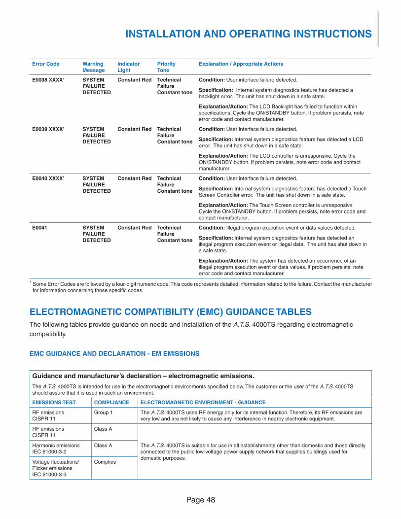
Page 48
INSTALLATION AND OPERATING INSTRUCTIONS
Error Code WarningMessage
IndicatorLight
PriorityTone
Explanation / Appropriate Actions
E0038 XXXX1 SYSTEM FAILURE DETECTED
Constant Red TechnicalFailureConstant tone
Condition: User interface failure detected.
Specifi cation: Internal system diagnostics feature has detected a backlight error. The unit has shut down in a safe state.
Explanation/Action: The LCD Backlight has failed to function within specifi cations. Cycle the ON/STANDBY button. If problem persists, note error code and contact manufacturer.
E0039 XXXX1 SYSTEM FAILURE DETECTED
Constant Red TechnicalFailureConstant tone
Condition: User interface failure detected.
Specifi cation: Internal system diagnostics feature has detected a LCD error. The unit has shut down in a safe state.
Explanation/Action: The LCD controller is unresponsive. Cycle the ON/STANDBY button. If problem persists, note error code and contact manufacturer.
E0040 XXXX1 SYSTEM FAILURE DETECTED
Constant Red TechnicalFailureConstant tone
Condition: User interface failure detected.
Specifi cation: Internal system diagnostics feature has detected a Touch Screen Controller error. The unit has shut down in a safe state.
Explanation/Action: The Touch Screen controller is unresponsive.
Cycle the ON/STANDBY button. If problem persists, note error code and
contact manufacturer.
E0041 SYSTEM
FAILURE
DETECTED
Constant Red Technical
Failure
Constant tone
Condition: Illegal program execution event or data values detected.
Specifi cation: Internal system diagnostics feature has detected an
illegal program execution event or illegal data. The unit has shut down in
a safe state.
Explanation/Action: The system has detected an occurrence of an
illegal program execution event or data values. If problem persists, note
error code and contact manufacturer.
1 Some Error Codes are followed by a four-digit numeric code. This code represents detailed information related to the failure. Contact the manufacturer
for information concerning those specifi c codes.
ELECTROMAGNETIC COMPATIBILITY (EMC) GUIDANCE TABLES
The following tables provide guidance on needs and installation of the A.T.S. 4000TS regarding electromagnetic
compatibility.
EMC GUIDANCE AND DECLARATION - EM EMISSIONS
Guidance and manufacturer’s declaration – electromagnetic emissions.
The A.T.S. 4000TS is intended for use in the electromagnetic environments specifi ed below. The customer or the user of the A.T.S. 4000TS should assure that it is used in such an environment.
EMISSIONS TEST COMPLIANCE ELECTROMAGNETIC ENVIRONMENT - GUIDANCE
RF emissionsCISPR 11
Group 1 The A.T.S. 4000TS uses RF energy only for its internal function. Therefore, its RF emissions are very low and are not likely to cause any interference in nearby electronic equipment.
RF emissions
CISPR 11
Class A
The A.T.S. 4000TS is suitable for use in all establishments other than domestic and those directly
connected to the public low-voltage power supply network that supplies buildings used for domestic purposes.
Harmonic emissions
IEC 61000-3-2
Class A
Voltage fl uctuations/
Flicker emissionsIEC 61000-3-3
Complies
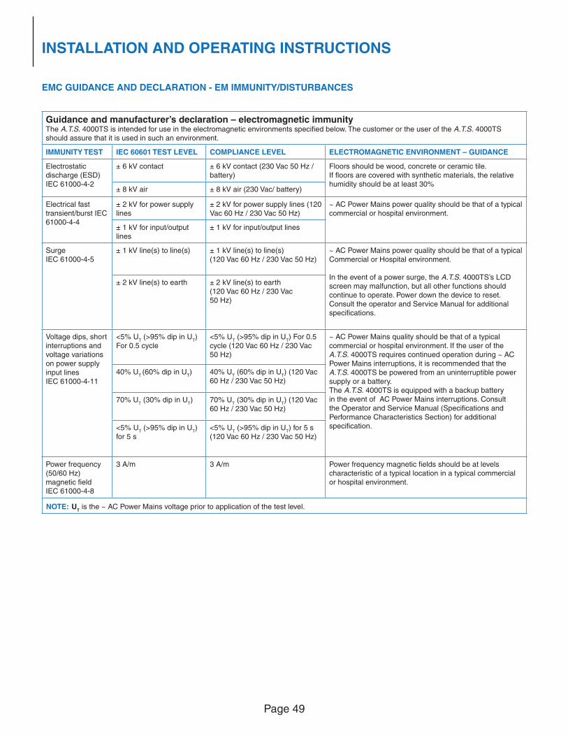
Page 49
INSTALLATION AND OPERATING INSTRUCTIONS
EMC GUIDANCE AND DECLARATION - EM IMMUNITY/DISTURBANCES
Guidance and manufacturer’s declaration – electromagnetic immunityThe A.T.S. 4000TS is intended for use in the electromagnetic environments specifi ed below. The customer or the user of the A.T.S. 4000TS should assure that it is used in such an environment.
IMMUNITY TEST IEC 60601 TEST LEVEL COMPLIANCE LEVEL ELECTROMAGNETIC ENVIRONMENT – GUIDANCE
Electrostatic discharge (ESD) IEC 61000-4-2
± 6 kV contact ± 6 kV contact (230 Vac 50 Hz / battery)
Floors should be wood, concrete or ceramic tile. If fl oors are covered with synthetic materials, the relative humidity should be at least 30%
± 8 kV air ± 8 kV air (230 Vac/ battery)
Electrical fast transient/burst IEC 61000-4-4
± 2 kV for power supply lines
± 2 kV for power supply lines (120 Vac 60 Hz / 230 Vac 50 Hz)
~ AC Power Mains power quality should be that of a typical commercial or hospital environment.
± 1 kV for input/output lines
± 1 kV for input/output lines
Surge IEC 61000-4-5
± 1 kV line(s) to line(s) ± 1 kV line(s) to line(s) (120 Vac 60 Hz / 230 Vac 50 Hz)
~ AC Power Mains power quality should be that of a typical Commercial or Hospital environment.
In the event of a power surge, the A.T.S. 4000TS’s LCD screen may malfunction, but all other functions should
continue to operate. Power down the device to reset.
Consult the operator and Service Manual for additional
specifi cations.
± 2 kV line(s) to earth ± 2 kV line(s) to earth
(120 Vac 60 Hz / 230 Vac
50 Hz)
Voltage dips, short
interruptions and
voltage variations
on power supply
input lines
IEC 61000-4-11
<5% UT (>95% dip in U
T)
For 0.5 cycle
<5% UT (>95% dip in U
T) For 0.5
cycle (120 Vac 60 Hz / 230 Vac
50 Hz)
~ AC Power Mains quality should be that of a typical
commercial or hospital environment. If the user of the
A.T.S. 4000TS requires continued operation during ~ AC
Power Mains interruptions, it is recommended that the
A.T.S. 4000TS be powered from an uninterruptible power
supply or a battery.
The A.T.S. 4000TS is equipped with a backup battery
in the event of AC Power Mains interruptions. Consult
the Operator and Service Manual (Specifi cations and
Performance Characteristics Section) for additional
specifi cation.
40% UT (60% dip in U
T) 40% U
T (60% dip in U
T) (120 Vac
60 Hz / 230 Vac 50 Hz)
70% UT (30% dip in U
T) 70% U
T (30% dip in U
T) (120 Vac
60 Hz / 230 Vac 50 Hz)
<5% UT (>95% dip in U
T)
for 5 s
<5% UT (>95% dip in U
T) for 5 s
(120 Vac 60 Hz / 230 Vac 50 Hz)
Power frequency
(50/60 Hz)
magnetic fi eldIEC 61000-4-8
3 A/m 3 A/m Power frequency magnetic fi elds should be at levels
characteristic of a typical location in a typical commercial or hospital environment.
NOTE: UT is the ~ AC Power Mains voltage prior to application of the test level.
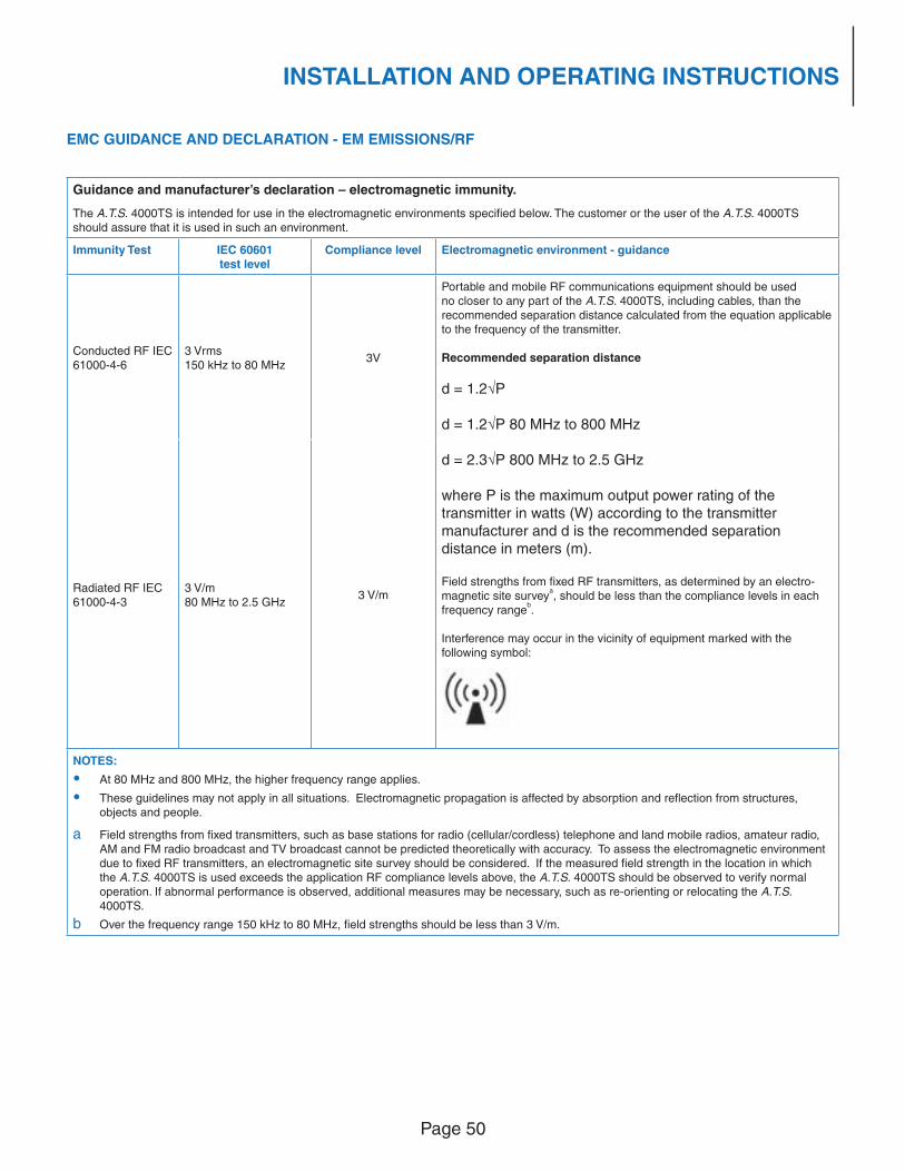
Page 50
INSTALLATION AND OPERATING INSTRUCTIONS
EMC GUIDANCE AND DECLARATION - EM EMISSIONS/RF
Guidance and manufacturer’s declaration – electromagnetic immunity.
The A.T.S. 4000TS is intended for use in the electromagnetic environments specifi ed below. The customer or the user of the A.T.S. 4000TS should assure that it is used in such an environment.
Immunity Test IEC 60601test level
Compliance level Electromagnetic environment - guidance
Conducted RF IEC 61000-4-6
3 Vrms150 kHz to 80 MHz
3V
Portable and mobile RF communications equipment should be used no closer to any part of the A.T.S. 4000TS, including cables, than the recommended separation distance calculated from the equation applicable to the frequency of the transmitter. Recommended separation distance
d = 1.2√P
d = 1.2√P 80 MHz to 800 MHz
d = 2.3√P 800 MHz to 2.5 GHz
where P is the maximum output power rating of the transmitter in watts (W) according to the transmitter manufacturer and d is the recommended separation distance in meters (m).
Field strengths from fi xed RF transmitters, as determined by an electro-
magnetic site surveya, should be less than the compliance levels in each
frequency rangeb.
Interference may occur in the vicinity of equipment marked with the
following symbol:
Radiated RF IEC
61000-4-3
3 V/m
80 MHz to 2.5 GHz3 V/m
NOTES:
• At 80 MHz and 800 MHz, the higher frequency range applies.
• These guidelines may not apply in all situations. Electromagnetic propagation is affected by absorption and refl ection from structures,
objects and people.
a Field strengths from fi xed transmitters, such as base stations for radio (cellular/cordless) telephone and land mobile radios, amateur radio, AM and FM radio broadcast and TV broadcast cannot be predicted theoretically with accuracy. To assess the electromagnetic environment
due to fi xed RF transmitters, an electromagnetic site survey should be considered. If the measured fi eld strength in the location in which
the A.T.S. 4000TS is used exceeds the application RF compliance levels above, the A.T.S. 4000TS should be observed to verify normal operation. If abnormal performance is observed, additional measures may be necessary, such as re-orienting or relocating the A.T.S. 4000TS.
b Over the frequency range 150 kHz to 80 MHz, fi eld strengths should be less than 3 V/m.
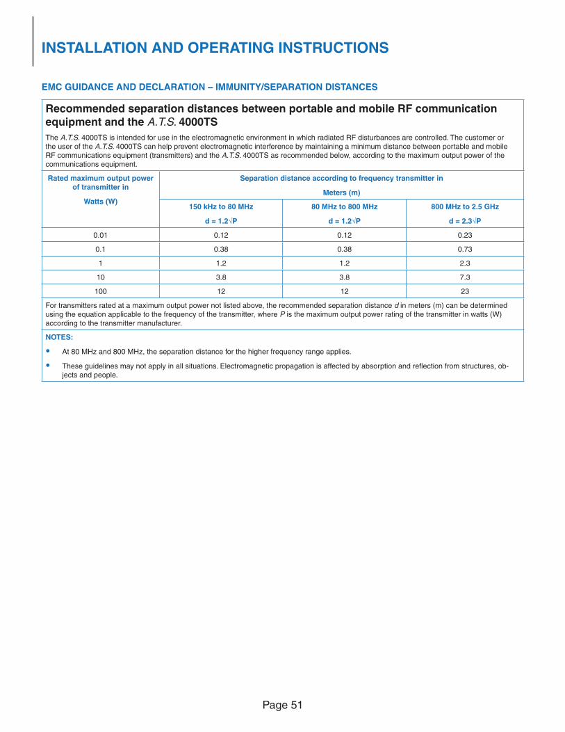
Page 51
INSTALLATION AND OPERATING INSTRUCTIONS
EMC GUIDANCE AND DECLARATION – IMMUNITY/SEPARATION DISTANCES
Recommended separation distances between portable and mobile RF communication
equipment and the A.T.S. 4000TS
The A.T.S. 4000TS is intended for use in the electromagnetic environment in which radiated RF disturbances are controlled. The customer or the user of the A.T.S. 4000TS can help prevent electromagnetic interference by maintaining a minimum distance between portable and mobile RF communications equipment (transmitters) and the A.T.S. 4000TS as recommended below, according to the maximum output power of the communications equipment.
Rated maximum output power of transmitter in
Watts (W)
Separation distance according to frequency transmitter in
Meters (m)
150 kHz to 80 MHz
d = 1.2√P
80 MHz to 800 MHz
d = 1.2√P
800 MHz to 2.5 GHz
d = 2.3√P
0.01 0.12 0.12 0.23
0.1 0.38 0.38 0.73
1 1.2 1.2 2.3
10 3.8 3.8 7.3
100 12 12 23
For transmitters rated at a maximum output power not listed above, the recommended separation distance d in meters (m) can be determined
using the equation applicable to the frequency of the transmitter, where P is the maximum output power rating of the transmitter in watts (W)
according to the transmitter manufacturer.
NOTES:
• At 80 MHz and 800 MHz, the separation distance for the higher frequency range applies.
• These guidelines may not apply in all situations. Electromagnetic propagation is affected by absorption and refl ection from structures, ob-
jects and people.
Page 52
MAINTENANCE
MAINTENANCE
GENERAL MAINTENANCE INFORMATION
While the A.T.S. 4000TS Tourniquet has been designed and manufactured to high industry standards, it is recommended that regular inspection and calibration be performed to ensure continual safe and effective operation. This section contains information to assist in the effort as well as serve as a guide to expediting unscheduled maintenance.
WARNING: No modifi cation of this equipment is allowed.
CAUTION: The A.T.S. 4000TS Tourniquet contains no user-serviceable parts inside. All internal parts and components must be serviced by an authorized and qualifi ed biomedical engineer or other person thoroughly familiar with electronic medical devices. Do not attempt to dismantle, modify or repair internal components. When testing, it is the user’s responsibility to ensure that the appropriate and proper measuring equipment is used. Improper or poorly maintained equipment may result in incorrect or misleading results.
LOP SENSOR CLEANING AND DISINFECTING
Clean or disinfect the Limb Occlusion Pressure (LOP) sensor before attaching to a new patient.
Cleaning
Unplug the LOP sensor from the A.T.S. 4000TS Tourniquet before cleaning. Clean the sensor and patient contact
surfaces with a soft cloth dampened (not dripping) in water or a mild detergent solution.
Disinfecting
Unplug the LOP sensor from the A.T.S. 4000TS Tourniquet before disinfecting. Disinfect the sensor by wiping the sensor and patient contact surfaces with disinfecting solution. Isopropyl alcohol is recommended as a disinfecting solution.
PERIODIC MAINTENANCE
This manual includes a blank Test and Analysis form. This is provided at the back of this manual. This form may be photocopied and used to document the visual, electrical safety and functional tests.
Cleaning
The exterior of the unit, including the touch screen, may be cleaned with a cloth that has been dampened (not
dripping) using a mild detergent solution with a neutral PH or isopropyl alcohol. The exterior of the cuff hose may be
cleaned using a mild detergent solution with a neutral PH or isopropyl alcohol. Reusable tourniquet cuffs should be
cleaned in accordance with their cuff package insert instructions.
External Visual Inspection
The unit should be inspected at regular intervals. It is recommended that a qualifi ed biomedical engineer or other
person thoroughly familiar with electronic medical devices within the healthcare organization perform a visual
inspection at least once every six months. Signifi cant inspection points are: External housing, touch screen, buttons,
pole clamp, missing/loose hardware, cuff ports, fuses (correct fuses used per labeling), labels (legible and complete).
The condition of the LOP sensor and power cord should also be carefully inspected. If any damage is discovered,
the system should be removed from service immediately along with all accessories and reported to the designated
individual responsible for equipment maintenance within the healthcare organization.
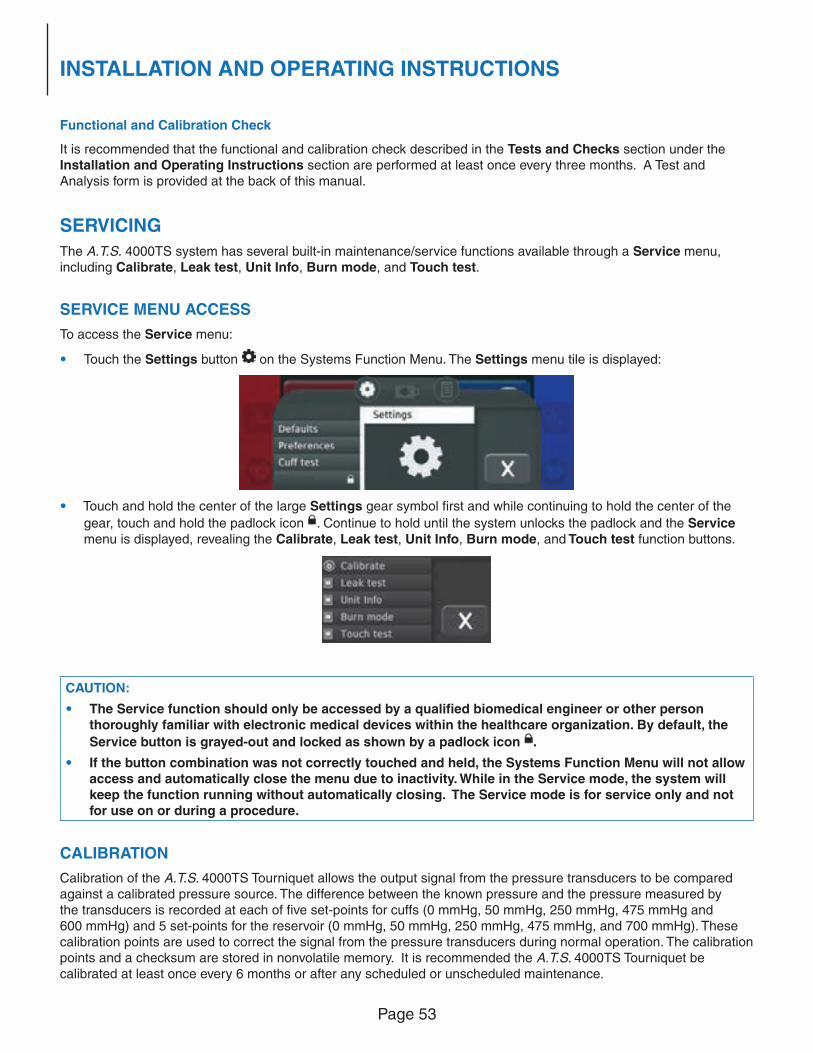
Page 53
INSTALLATION AND OPERATING INSTRUCTIONS
Functional and Calibration Check
It is recommended that the functional and calibration check described in the Tests and Checks section under the Installation and Operating Instructions section are performed at least once every three months. A Test and Analysis form is provided at the back of this manual.
SERVICING
The A.T.S. 4000TS system has several built-in maintenance/service functions available through a Service menu, including Calibrate, Leak test, Unit Info, Burn mode, and Touch test.
SERVICE MENU ACCESS
To access the Service menu:
• Touch the Settings button on the Systems Function Menu. The Settings menu tile is displayed:
• Touch and hold the center of the large Settings gear symbol fi rst and while continuing to hold the center of the
gear, touch and hold the padlock icon . Continue to hold until the system unlocks the padlock and the Service menu is displayed, revealing the Calibrate, Leak test, Unit Info, Burn mode, and Touch test function buttons.
CAUTION:
• The Service function should only be accessed by a qualifi ed biomedical engineer or other person thoroughly familiar with electronic medical devices within the healthcare organization. By default, the
Service button is grayed-out and locked as shown by a padlock icon .
• If the button combination was not correctly touched and held, the Systems Function Menu will not allow access and automatically close the menu due to inactivity. While in the Service mode, the system will keep the function running without automatically closing. The Service mode is for service only and not for use on or during a procedure.
CALIBRATION
Calibration of the A.T.S. 4000TS Tourniquet allows the output signal from the pressure transducers to be compared against a calibrated pressure source. The difference between the known pressure and the pressure measured by the transducers is recorded at each of fi ve set-points for cuffs (0 mmHg, 50 mmHg, 250 mmHg, 475 mmHg and 600 mmHg) and 5 set-points for the reservoir (0 mmHg, 50 mmHg, 250 mmHg, 475 mmHg, and 700 mmHg). These calibration points are used to correct the signal from the pressure transducers during normal operation. The calibration points and a checksum are stored in nonvolatile memory. It is recommended the A.T.S. 4000TS Tourniquet be calibrated at least once every 6 months or after any scheduled or unscheduled maintenance.
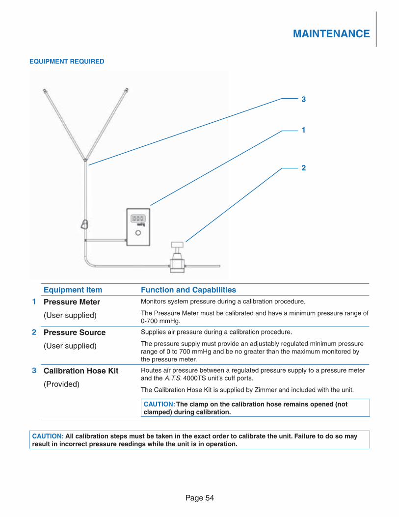
Page 54
MAINTENANCE
EQUIPMENT REQUIRED
Equipment Item Function and Capabilities
1 Pressure Meter
(User supplied)
Monitors system pressure during a calibration procedure.
The Pressure Meter must be calibrated and have a minimum pressure range of 0-700 mmHg.
2 Pressure Source
(User supplied)
Supplies air pressure during a calibration procedure.
The pressure supply must provide an adjustably regulated minimum pressure range of 0 to 700 mmHg and be no greater than the maximum monitored by the pressure meter.
3 Calibration Hose Kit
(Provided)
Routes air pressure between a regulated pressure supply to a pressure meter and the A.T.S. 4000TS unit’s cuff ports.
The Calibration Hose Kit is supplied by Zimmer and included with the unit.
CAUTION: The clamp on the calibration hose remains opened (not clamped) during calibration.
CAUTION: All calibration steps must be taken in the exact order to calibrate the unit. Failure to do so may result in incorrect pressure readings while the unit is in operation.
3
2
1
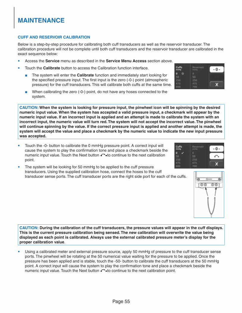
Page 55
MAINTENANCE
CUFF AND RESERVOIR CALIBRATION
Below is a step-by-step procedure for calibrating both cuff transducers as well as the reservoir transducer. The calibration procedure will not be complete until both cuff transducers and the reservoir transducer are calibrated in the exact sequence below:
• Access the Service menu as described in the Service Menu Access section above.
• Touch the Calibrate button to access the Calibration function interface.
■ The system will enter the Calibrate function and immediately start looking for the specifi ed pressure input. The fi rst input is the zero (-0-) point (atmospheric pressure) for the cuff transducers. This will calibrate both cuffs at the same time.
■ When calibrating the zero (-0-) point, do not have any hoses connected to the system.
CAUTION: When the system is looking for pressure input, the pinwheel icon will be spinning by the desired numeric input value. When the system has accepted a valid pressure input, a checkmark will appear by the numeric input value. If an incorrect input is applied and an attempt is made to calibrate the system with an incorrect input, the numeric value will turn red. The system will not accept the incorrect value. The pinwheel will continue spinning by the value. If the correct pressure input is applied and another attempt is made, the system will accept the value and place a checkmark by the numeric value to indicate the new input pressure was accepted.
• Touch the -0- button to calibrate the 0 mmHg pressure point. A correct input will cause the system to play the confi rmation tone and place a checkmark beside the numeric input value. Touch the Next button to continue to the next calibration point.
• The system will be looking for 50 mmHg to be applied to the cuff pressure transducers. Using the supplied calibration hose, connect the hoses to the cuff transducer sense ports. The cuff transducer ports are the right side port for each of the cuffs.
CAUTION: During the calibration of the cuff transducers, the pressure values will appear in the cuff displays. This is the current pressure calibration being sensed. The new calibration will overwrite the value being displayed as each point is calibrated. Always use the external calibrated pressure meter’s display for the proper calibration value.
• Using a calibrated meter and external pressure source, apply 50 mmHg of pressure to the cuff transducer sense ports. The pinwheel will be rotating at the 50 numerical value waiting for the pressure to be applied. Once the pressure has been applied and is stable, touch the -50- button to calibrate the cuff transducers at the 50 mmHg point. A correct input will cause the system to play the confi rmation tone and place a checkmark beside the numeric input value. Touch the Next button to continue to the next calibration point.
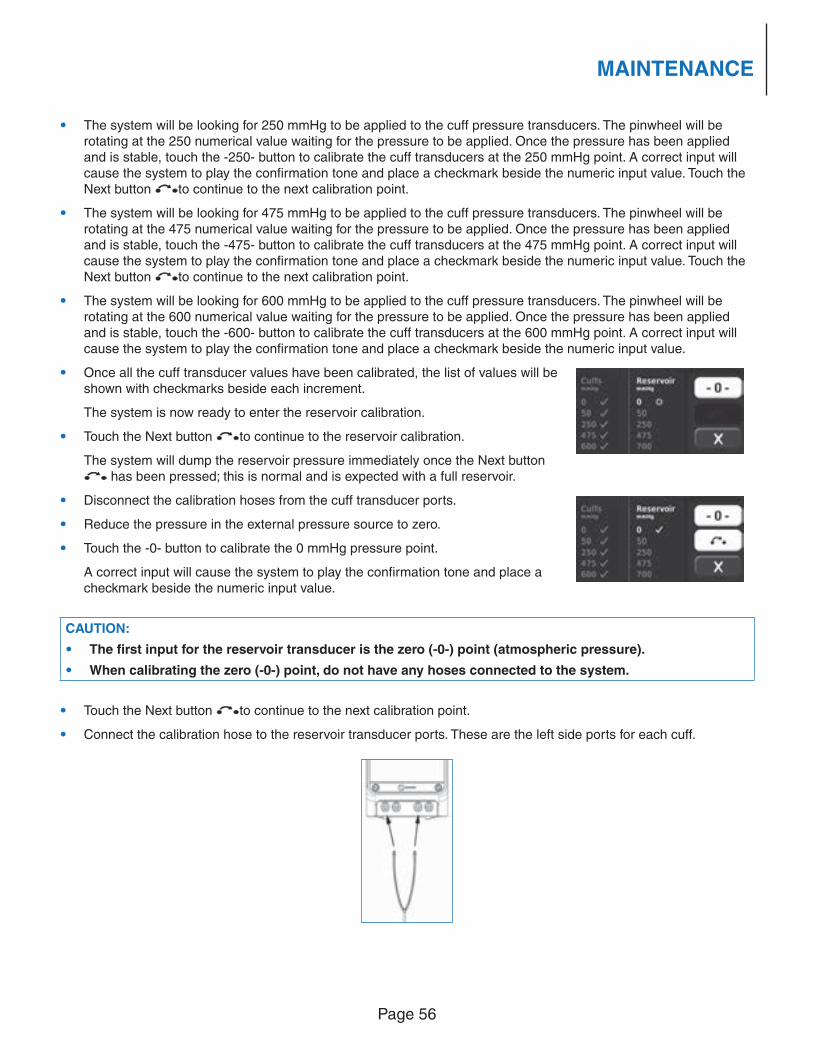
Page 56
MAINTENANCE
• The system will be looking for 250 mmHg to be applied to the cuff pressure transducers. The pinwheel will be rotating at the 250 numerical value waiting for the pressure to be applied. Once the pressure has been applied and is stable, touch the -250- button to calibrate the cuff transducers at the 250 mmHg point. A correct input will cause the system to play the confi rmation tone and place a checkmark beside the numeric input value. Touch the Next button to continue to the next calibration point.
• The system will be looking for 475 mmHg to be applied to the cuff pressure transducers. The pinwheel will be rotating at the 475 numerical value waiting for the pressure to be applied. Once the pressure has been applied and is stable, touch the -475- button to calibrate the cuff transducers at the 475 mmHg point. A correct input will cause the system to play the confi rmation tone and place a checkmark beside the numeric input value. Touch the Next button to continue to the next calibration point.
• The system will be looking for 600 mmHg to be applied to the cuff pressure transducers. The pinwheel will be rotating at the 600 numerical value waiting for the pressure to be applied. Once the pressure has been applied and is stable, touch the -600- button to calibrate the cuff transducers at the 600 mmHg point. A correct input will cause the system to play the confi rmation tone and place a checkmark beside the numeric input value.
• Once all the cuff transducer values have been calibrated, the list of values will be shown with checkmarks beside each increment.
The system is now ready to enter the reservoir calibration.
• Touch the Next button to continue to the reservoir calibration.
The system will dump the reservoir pressure immediately once the Next button has been pressed; this is normal and is expected with a full reservoir.
• Disconnect the calibration hoses from the cuff transducer ports.
• Reduce the pressure in the external pressure source to zero.
• Touch the -0- button to calibrate the 0 mmHg pressure point.
A correct input will cause the system to play the confi rmation tone and place a checkmark beside the numeric input value.
CAUTION:
• The fi rst input for the reservoir transducer is the zero (-0-) point (atmospheric pressure).
• When calibrating the zero (-0-) point, do not have any hoses connected to the system.
• Touch the Next button to continue to the next calibration point.
• Connect the calibration hose to the reservoir transducer ports. These are the left side ports for each cuff.
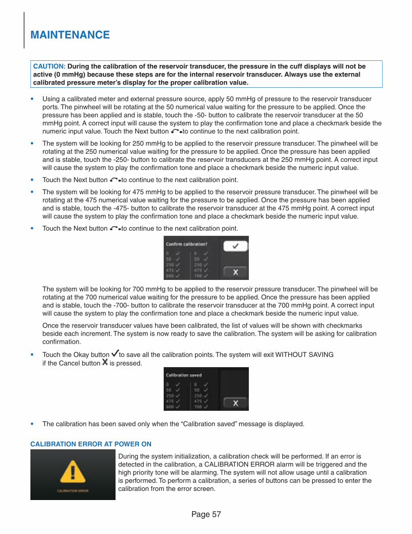
Page 57
MAINTENANCE
CAUTION: During the calibration of the reservoir transducer, the pressure in the cuff displays will not be active (0 mmHg) because these steps are for the internal reservoir transducer. Always use the external calibrated pressure meter’s display for the proper calibration value.
• Using a calibrated meter and external pressure source, apply 50 mmHg of pressure to the reservoir transducer ports. The pinwheel will be rotating at the 50 numerical value waiting for the pressure to be applied. Once the pressure has been applied and is stable, touch the -50- button to calibrate the reservoir transducer at the 50 mmHg point. A correct input will cause the system to play the confi rmation tone and place a checkmark beside the numeric input value. Touch the Next button to continue to the next calibration point.
• The system will be looking for 250 mmHg to be applied to the reservoir pressure transducer. The pinwheel will be rotating at the 250 numerical value waiting for the pressure to be applied. Once the pressure has been applied and is stable, touch the -250- button to calibrate the reservoir transducers at the 250 mmHg point. A correct input will cause the system to play the confi rmation tone and place a checkmark beside the numeric input value.
• Touch the Next button to continue to the next calibration point.
• The system will be looking for 475 mmHg to be applied to the reservoir pressure transducer. The pinwheel will be rotating at the 475 numerical value waiting for the pressure to be applied. Once the pressure has been applied and is stable, touch the -475- button to calibrate the reservoir transducer at the 475 mmHg point. A correct input will cause the system to play the confi rmation tone and place a checkmark beside the numeric input value.
• Touch the Next button to continue to the next calibration point.
The system will be looking for 700 mmHg to be applied to the reservoir pressure transducer. The pinwheel will be rotating at the 700 numerical value waiting for the pressure to be applied. Once the pressure has been applied and is stable, touch the -700- button to calibrate the reservoir transducer at the 700 mmHg point. A correct input will cause the system to play the confi rmation tone and place a checkmark beside the numeric input value.
Once the reservoir transducer values have been calibrated, the list of values will be shown with checkmarks beside each increment. The system is now ready to save the calibration. The system will be asking for calibration confi rmation.
• Touch the Okay button to save all the calibration points. The system will exit WITHOUT SAVING
if the Cancel button is pressed.
• The calibration has been saved only when the “Calibration saved” message is displayed.
CALIBRATION ERROR AT POWER ON
During the system initialization, a calibration check will be performed. If an error is detected in the calibration, a CALIBRATION ERROR alarm will be triggered and the high priority tone will be alarming. The system will not allow usage until a calibration is performed. To perform a calibration, a series of buttons can be pressed to enter the calibration from the error screen.
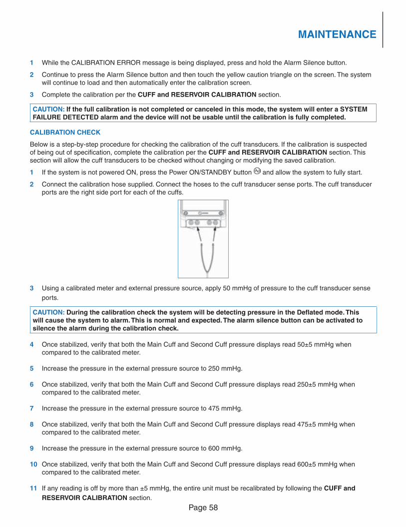
Page 58
MAINTENANCE
1 While the CALIBRATION ERROR message is being displayed, press and hold the Alarm Silence button.
2 Continue to press the Alarm Silence button and then touch the yellow caution triangle on the screen. The system will continue to load and then automatically enter the calibration screen.
3 Complete the calibration per the CUFF and RESERVOIR CALIBRATION section.
CAUTION: If the full calibration is not completed or canceled in this mode, the system will enter a SYSTEM FAILURE DETECTED alarm and the device will not be usable until the calibration is fully completed.
CALIBRATION CHECK
Below is a step-by-step procedure for checking the calibration of the cuff transducers. If the calibration is suspected of being out of specifi cation, complete the calibration per the CUFF and RESERVOIR CALIBRATION section. This section will allow the cuff transducers to be checked without changing or modifying the saved calibration.
1 If the system is not powered ON, press the Power ON/STANDBY button and allow the system to fully start.
2 Connect the calibration hose supplied. Connect the hoses to the cuff transducer sense ports. The cuff transducer ports are the right side port for each of the cuffs.
3 Using a calibrated meter and external pressure source, apply 50 mmHg of pressure to the cuff transducer sense
ports.
CAUTION: During the calibration check the system will be detecting pressure in the Defl ated mode. This will cause the system to alarm. This is normal and expected. The alarm silence button can be activated to silence the alarm during the calibration check.
4 Once stabilized, verify that both the Main Cuff and Second Cuff pressure displays read 50±5 mmHg when compared to the calibrated meter.
5 Increase the pressure in the external pressure source to 250 mmHg.
6 Once stabilized, verify that both the Main Cuff and Second Cuff pressure displays read 250±5 mmHg when compared to the calibrated meter.
7 Increase the pressure in the external pressure source to 475 mmHg.
8 Once stabilized, verify that both the Main Cuff and Second Cuff pressure displays read 475±5 mmHg when compared to the calibrated meter.
9 Increase the pressure in the external pressure source to 600 mmHg.
10 Once stabilized, verify that both the Main Cuff and Second Cuff pressure displays read 600±5 mmHg when compared to the calibrated meter.
11 If any reading is off by more than ±5 mmHg, the entire unit must be recalibrated by following the CUFF and
RESERVOIR CALIBRATION section.
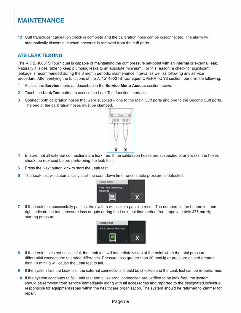
Page 59
MAINTENANCE
12 Cuff transducer calibration check is complete and the calibration hose can be disconnected. The alarm will
automatically discontinue when pressure is removed from the cuff ports.
ATS LEAK TESTING
The A.T.S. 4000TS Tourniquet is capable of maintaining the cuff pressure set-point with an internal or external leak.
Naturally it is desirable to keep plumbing leaks to an absolute minimum. For this reason, a check for signifi cant
leakage is recommended during the 6 month periodic maintenance interval as well as following any service
procedure. After verifying the functions of the A.T.S. 4000TS Tourniquet OPERATIONS section, perform the following:
1 Access the Service menu as described in the Service Menu Access section above.
2 Touch the Leak Test button to access the Leak Test function interface.
3 Connect both calibration hoses that were supplied – one to the Main Cuff ports and one to the Second Cuff ports.
The end of the calibration hoses must be clamped.
4 Ensure that all external connections are leak free. If the calibration hoses are suspected of any leaks, the hoses
should be replaced before performing the leak test.
5 Press the Next button to start the Leak test
6 The Leak test will automatically start the countdown timer once stable pressure is detected.
7 If the Leak test successfully passes, the system will issue a passing result. The numbers in the bottom left and
right indicate the total pressure loss or gain during the Leak test time period from approximately 475 mmHg
starting pressure.
8 If the Leak test is not successful, the Leak test will immediately stop at the point when the total pressure
differential exceeds the tolerated differentia. Pressure loss greater than 30 mmHg or pressure gain of greater
than 10 mmHg will cause the Leak test to fail.
9 If the system fails the Leak test, the external connections should be checked and the Leak test can be re-performed.
10 If the system continues to fail Leak test and all external connection are verifi ed to be leak-free, the system
should be removed from service immediately along with all accessories and reported to the designated individual
responsible for equipment repair within the healthcare organization. The system should be returned to Zimmer for
repair.
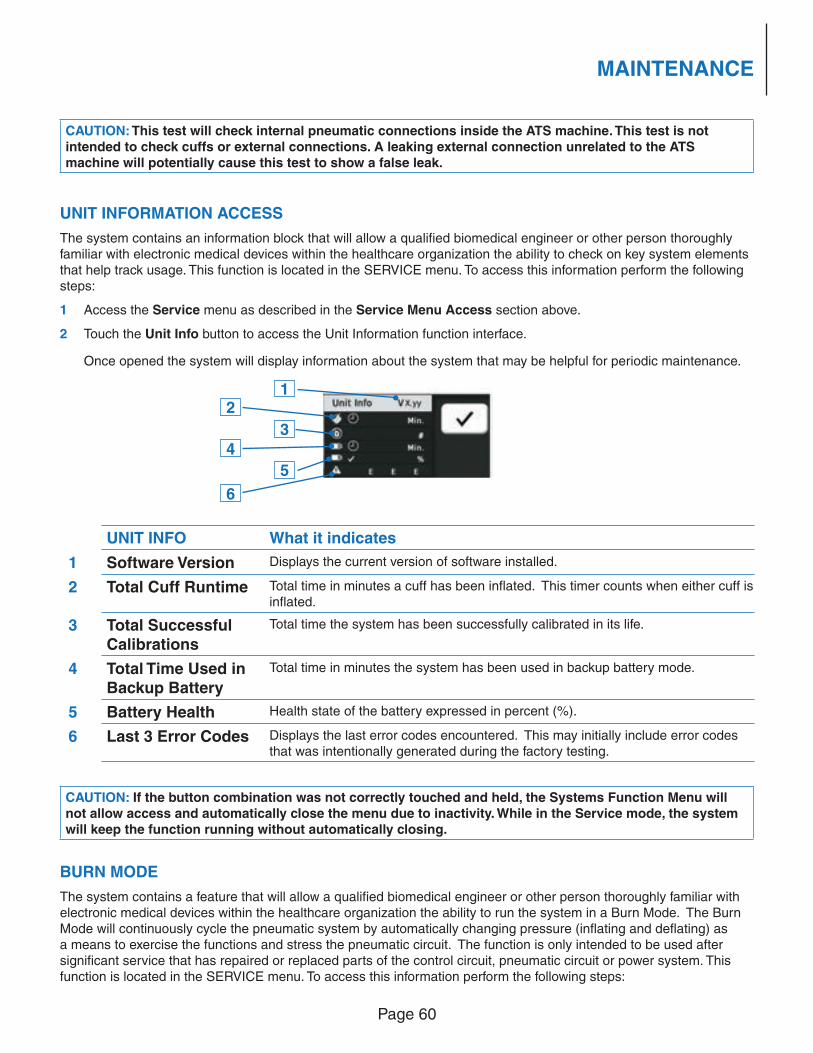
Page 60
MAINTENANCE
CAUTION: This test will check internal pneumatic connections inside the ATS machine. This test is not intended to check cuffs or external connections. A leaking external connection unrelated to the ATS machine will potentially cause this test to show a false leak.
UNIT INFORMATION ACCESS
The system contains an information block that will allow a qualifi ed biomedical engineer or other person thoroughly familiar with electronic medical devices within the healthcare organization the ability to check on key system elements that help track usage. This function is located in the SERVICE menu. To access this information perform the following steps:
1 Access the Service menu as described in the Service Menu Access section above.
2 Touch the Unit Info button to access the Unit Information function interface.
Once opened the system will display information about the system that may be helpful for periodic maintenance.
UNIT INFO What it indicates
1 Software Version Displays the current version of software installed.
2 Total Cuff Runtime Total time in minutes a cuff has been infl ated. This timer counts when either cuff is infl ated.
3 Total Successful Calibrations
Total time the system has been successfully calibrated in its life.
4 Total Time Used in Backup Battery
Total time in minutes the system has been used in backup battery mode.
5 Battery Health Health state of the battery expressed in percent (%).
6 Last 3 Error Codes Displays the last error codes encountered. This may initially include error codes that was intentionally generated during the factory testing.
CAUTION: If the button combination was not correctly touched and held, the Systems Function Menu will not allow access and automatically close the menu due to inactivity. While in the Service mode, the system will keep the function running without automatically closing.
BURN MODE
The system contains a feature that will allow a qualifi ed biomedical engineer or other person thoroughly familiar with electronic medical devices within the healthcare organization the ability to run the system in a Burn Mode. The Burn Mode will continuously cycle the pneumatic system by automatically changing pressure (infl ating and defl ating) as a means to exercise the functions and stress the pneumatic circuit. The function is only intended to be used after signifi cant service that has repaired or replaced parts of the control circuit, pneumatic circuit or power system. This function is located in the SERVICE menu. To access this information perform the following steps:
12
3
4
5
6
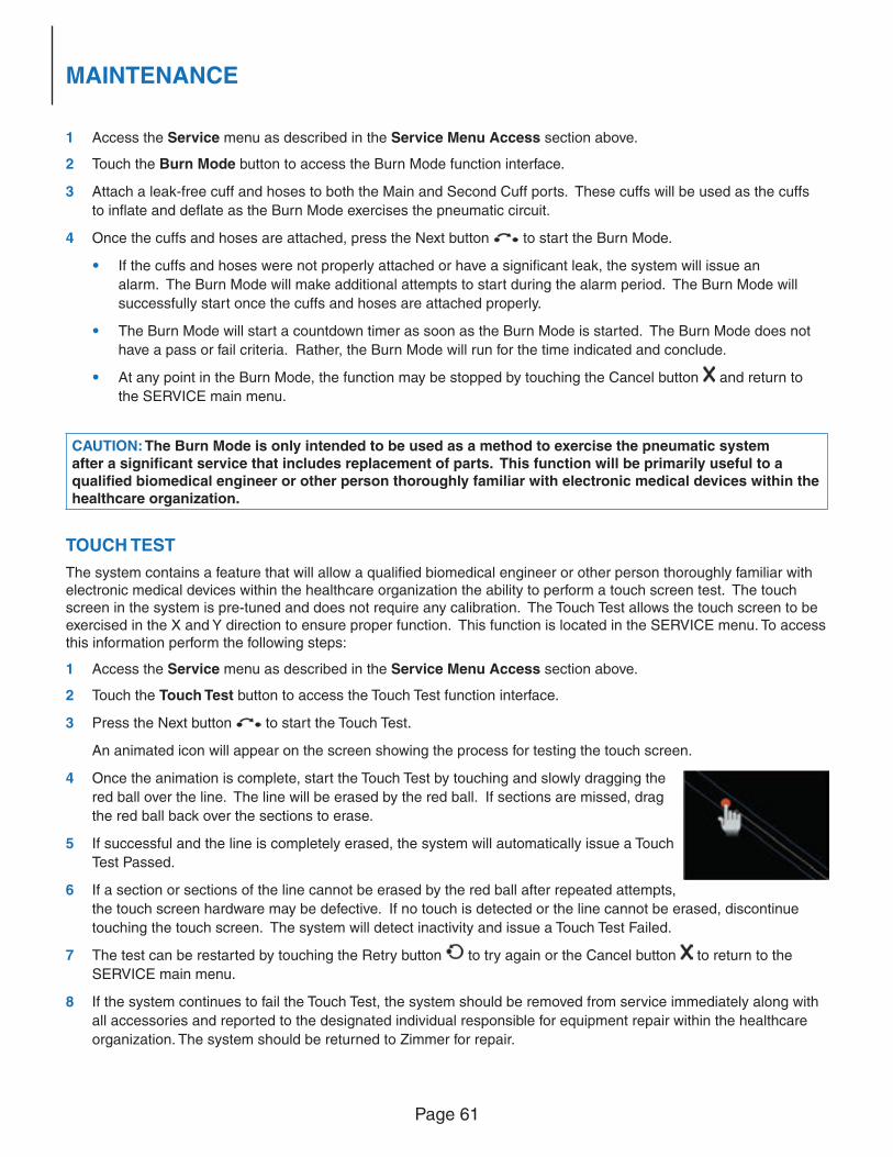
Page 61
MAINTENANCE
1 Access the Service menu as described in the Service Menu Access section above.
2 Touch the Burn Mode button to access the Burn Mode function interface.
3 Attach a leak-free cuff and hoses to both the Main and Second Cuff ports. These cuffs will be used as the cuffs
to infl ate and defl ate as the Burn Mode exercises the pneumatic circuit.
4 Once the cuffs and hoses are attached, press the Next button to start the Burn Mode.
• If the cuffs and hoses were not properly attached or have a signifi cant leak, the system will issue an
alarm. The Burn Mode will make additional attempts to start during the alarm period. The Burn Mode will
successfully start once the cuffs and hoses are attached properly.
• The Burn Mode will start a countdown timer as soon as the Burn Mode is started. The Burn Mode does not
have a pass or fail criteria. Rather, the Burn Mode will run for the time indicated and conclude.
• At any point in the Burn Mode, the function may be stopped by touching the Cancel button and return to
the SERVICE main menu.
CAUTION: The Burn Mode is only intended to be used as a method to exercise the pneumatic system after a signifi cant service that includes replacement of parts. This function will be primarily useful to a qualifi ed biomedical engineer or other person thoroughly familiar with electronic medical devices within the healthcare organization.
TOUCH TEST
The system contains a feature that will allow a qualifi ed biomedical engineer or other person thoroughly familiar with electronic medical devices within the healthcare organization the ability to perform a touch screen test. The touch screen in the system is pre-tuned and does not require any calibration. The Touch Test allows the touch screen to be exercised in the X and Y direction to ensure proper function. This function is located in the SERVICE menu. To access this information perform the following steps:
1 Access the Service menu as described in the Service Menu Access section above.
2 Touch the Touch Test button to access the Touch Test function interface.
3 Press the Next button to start the Touch Test.
An animated icon will appear on the screen showing the process for testing the touch screen.
4 Once the animation is complete, start the Touch Test by touching and slowly dragging the
red ball over the line. The line will be erased by the red ball. If sections are missed, drag
the red ball back over the sections to erase.
5 If successful and the line is completely erased, the system will automatically issue a Touch
Test Passed.
6 If a section or sections of the line cannot be erased by the red ball after repeated attempts,
the touch screen hardware may be defective. If no touch is detected or the line cannot be erased, discontinue
touching the touch screen. The system will detect inactivity and issue a Touch Test Failed.
7 The test can be restarted by touching the Retry button to try again or the Cancel button to return to the
SERVICE main menu.
8 If the system continues to fail the Touch Test, the system should be removed from service immediately along with
all accessories and reported to the designated individual responsible for equipment repair within the healthcare
organization. The system should be returned to Zimmer for repair.
Page 62
MAINTENANCE
PROTECTIVE EARTH RESISTANCE TESTING
CAUTION: The A.T.S. 4000TS System must meet the protective earth resistance requirements before performing any additional electrical safety checks.
The protective earth resistance measurement should be conducted with the power cord attached to appliance inlet. The test equipment used must be able to deliver at least 200mA into 500mΩ. The open circuit voltage shall not exceed 24V. Consult the test equipment manufacturer to ensure these specifi cations are met. Measure the protective earth resistance between the protective earth pin (ground pin) of the power cord and the exposed aluminum chassis at the back of the device. The resistance reading should not exceed 300mΩ. The integrity of the earth conductor of the power cord should be performed during normal maintenance intervals. During the protective earth resistance testing, the power cord should be fl exed along its entire length. If during fl exing, changes in resistance are observed, the power cord’s protective earth conductor is presumed to be damaged and the power cord should be immediately replaced.
EARTH (EQUIPMENT) LEAKAGE CURRENT TESTING
The earth (equipment) leakage current is the recommended leakage current test. The applied parts of the A.T.S. 4000TS are electrically insulated from the user/patient and are constructed from a non-conductive material. The maximum allowable leakage current is 500μA in a single fault condition.
INSULATION RESISTANCE TESTING
CAUTION: The A.T.S. 4000TS System must be disconnected from supply mains when measuring the insulation resistance.
The insulation resistance testing is conducted by measuring the Mains Part to the Protective Earth ground. The test equipment used shall be capable of performing the measurements with 500VDC. The insulation resistance will be a very high level since the insulation is intended to provide no means for electrical conductivity. Therefore, values >50MΩ will be considered acceptable reference value. Measurements that show a signifi cant decrease from the previous measured value indicates a problem.
BACKUP BATTERY SERVICE
The A.T.S. 4000TS System is equipped with a Lithium Ion backup battery. The battery is designed to last for years when properly maintained. The system has a built-in battery charger that maintains the battery power as long as ~ AC Power Mains is present. Continuous cycles of deep discharge and/or storage in a high temperature environment will shorten the life of the battery. Infrequent short-term use of the battery and storage in a room temperature environment will result in maximum life. It is recommended that the battery in the A.T.S. 4000TS Tourniquet System be replaced whenever the battery health has reached 50% as indicated in the UNIT INFO function in the SERVICE feature.
CAUTION: If the A.T.S. 4000TS System is not expected to be used for an extended period of time (>90 days), the battery should be removed and stored.
The battery may be replaced or removed for storage by removing the battery compartment cover. The following instructions describe the battery replacement:
1 Remove the two battery compartment cover screws located at the back of the device.
2 With the screws removed, the battery can be accessed. Allow the battery to slide out, but continue to hold it from falling.
Page 63
MAINTENANCE
3 Using needle-nose pliers, carefully unplug the battery clip from the system by lifting the tab and pulling free.
4 Replace with a new Zimmer battery and re-install the battery compartment cover.
The A.T.S. 4000TS System will immediately evaluate the new battery and begin charging.
CAUTION: The A.T.S. 4000TS System is designed to use Zimmer batteries only. Do not use any battery other than the Zimmer battery. The system will not allow unauthorized batteries. Do not attempt to open, modify or repair the battery. Replace the battery with a new Zimmer battery when the battery health is depleted.
CAUTION: The A.T.S. 4000TS System should be plugged in at least 10 hours before putting back into use to ensure a full battery charge in case of emergency power loss.
BATTERY-HANDLING RECOMMENDATIONS
• Do not dismantle, open or shred the battery.
• Do not expose the battery to heat or fi re. Avoid storage in direct sunlight.
• Do not short-circuit the battery. Do not store cells or batteries haphazardly in a box or drawer where they may short-circuit each other or be short-circuited by other metal objects.
• Do not remove a battery from its original packaging until required for use.
• Do not subject a battery to mechanical shock.
• In the event of a cell leaking, do not allow the liquid to come in contact with the skin or eyes. If contact has been made, wash the affected area with copious amounts of water and seek medical advice.
• Do not use any charger other than that specifi cally provided for use with the equipment.
• Observe the plus (+) and minus (–) marks on the battery and ensure correct use.
• Do not use any battery which is not designed for use with the equipment.
• Keep cells and batteries out of the reach of children.
• Seek medical advice immediately if a cell or a battery has been swallowed.
• Always purchase the correct battery for the equipment.
• Keep batteries clean and dry.
CAUTION: After extended periods of storage, it may be necessary to charge and discharge the battery several times to obtain maximum performance.
• Secondary batteries need to be charged before use. Refer to the A.T.S. 4000TS Operator/Service Manual for proper charging instructions.
• Secondary batteries give their best performance when they are operated at normal room temperature (20 °C ± 5 °C).
• Retain the original product literature for future reference.
• Use only the battery in the application for which it was intended.
• Dispose of properly.
Notice: Battery Pack Disposal: The battery is of a Lithium-Ion type. When the battery reaches the end of its useful life, the battery should be disposed of by a qualifi ed recycler or hazardous materials handler. Do not mix this battery with the solid waste stream. Contact your local recycler or hazardous material handler for recycling or disposal information.
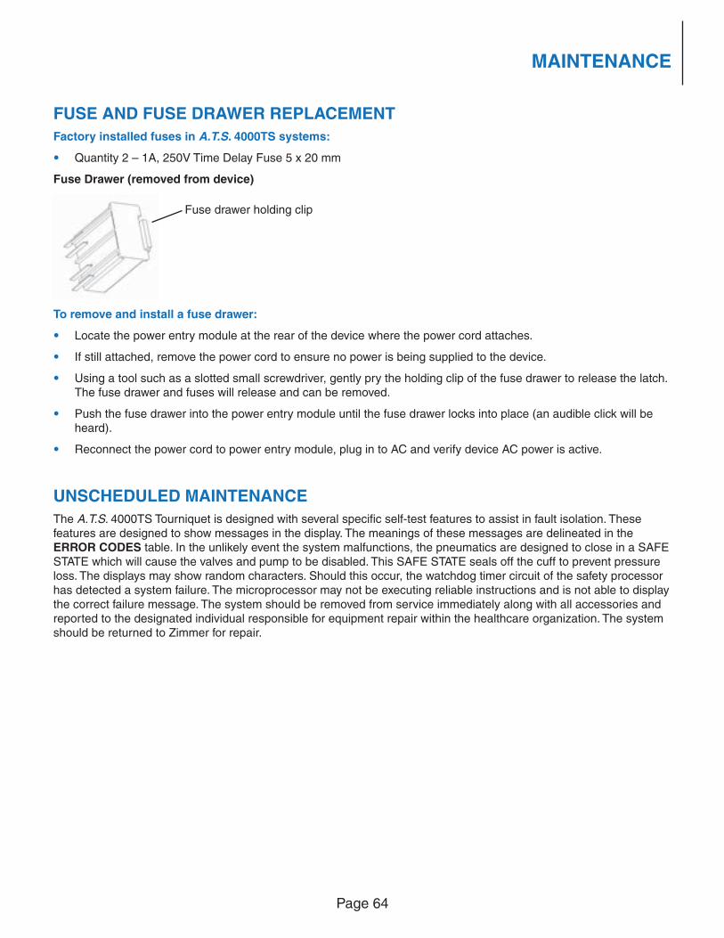
Page 64
MAINTENANCE
FUSE AND FUSE DRAWER REPLACEMENT
Factory installed fuses in A.T.S. 4000TS systems:
• Quantity 2 – 1A, 250V Time Delay Fuse 5 x 20 mm
Fuse Drawer (removed from device)
To remove and install a fuse drawer:
• Locate the power entry module at the rear of the device where the power cord attaches.
• If still attached, remove the power cord to ensure no power is being supplied to the device.
• Using a tool such as a slotted small screwdriver, gently pry the holding clip of the fuse drawer to release the latch. The fuse drawer and fuses will release and can be removed.
• Push the fuse drawer into the power entry module until the fuse drawer locks into place (an audible click will be heard).
• Reconnect the power cord to power entry module, plug in to AC and verify device AC power is active.
UNSCHEDULED MAINTENANCE
The A.T.S. 4000TS Tourniquet is designed with several specifi c self-test features to assist in fault isolation. These features are designed to show messages in the display. The meanings of these messages are delineated in the ERROR CODES table. In the unlikely event the system malfunctions, the pneumatics are designed to close in a SAFE STATE which will cause the valves and pump to be disabled. This SAFE STATE seals off the cuff to prevent pressure loss. The displays may show random characters. Should this occur, the watchdog timer circuit of the safety processor has detected a system failure. The microprocessor may not be executing reliable instructions and is not able to display the correct failure message. The system should be removed from service immediately along with all accessories and reported to the designated individual responsible for equipment repair within the healthcare organization. The system should be returned to Zimmer for repair.
Fuse drawer holding clip
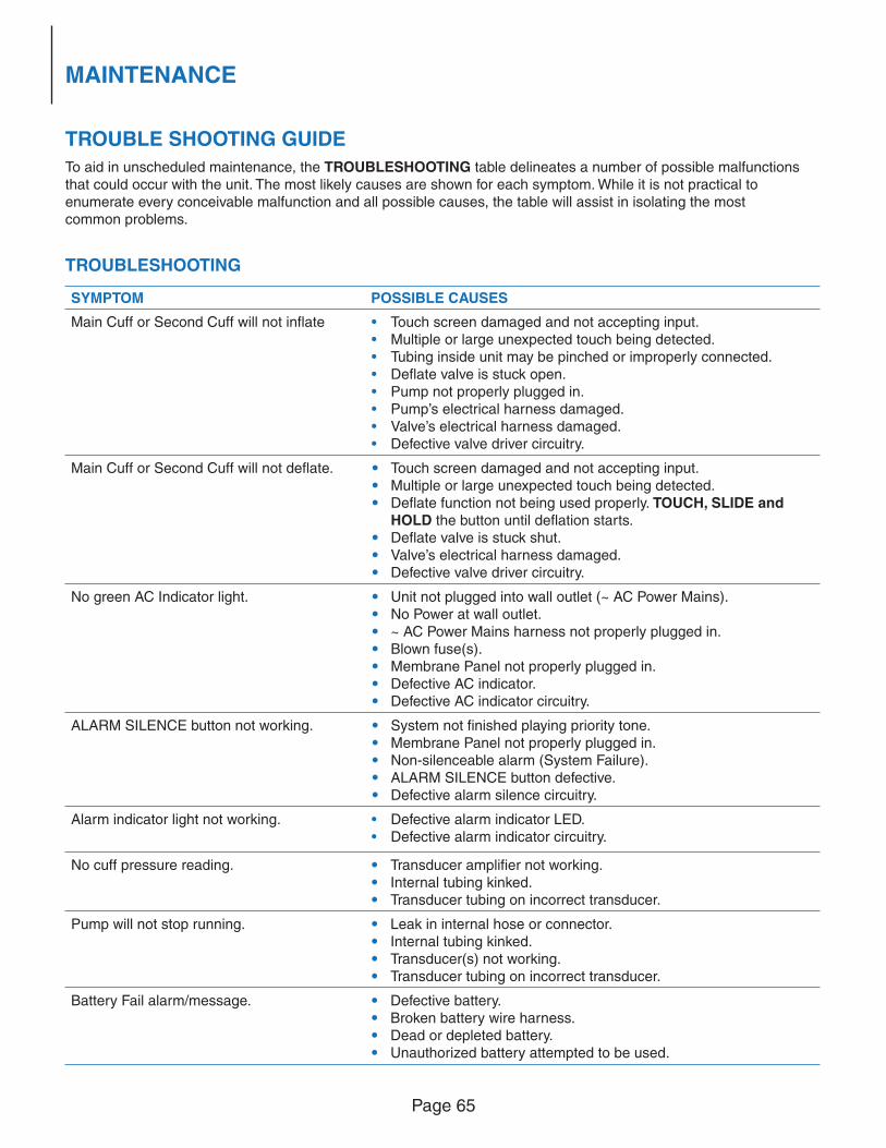
Page 65
MAINTENANCE
TROUBLE SHOOTING GUIDE
To aid in unscheduled maintenance, the TROUBLESHOOTING table delineates a number of possible malfunctions that could occur with the unit. The most likely causes are shown for each symptom. While it is not practical to enumerate every conceivable malfunction and all possible causes, the table will assist in isolating the most common problems.
TROUBLESHOOTING
SYMPTOM POSSIBLE CAUSES
Main Cuff or Second Cuff will not infl ate • Touch screen damaged and not accepting input.• Multiple or large unexpected touch being detected.• Tubing inside unit may be pinched or improperly connected.• Defl ate valve is stuck open.• Pump not properly plugged in.• Pump’s electrical harness damaged. • Valve’s electrical harness damaged.• Defective valve driver circuitry.
Main Cuff or Second Cuff will not defl ate. • Touch screen damaged and not accepting input. • Multiple or large unexpected touch being detected. • Defl ate function not being used properly. TOUCH, SLIDE and
HOLD the button until defl ation starts. • Defl ate valve is stuck shut. • Valve’s electrical harness damaged. • Defective valve driver circuitry.
No green AC Indicator light. • Unit not plugged into wall outlet (~ AC Power Mains). • No Power at wall outlet. • ~ AC Power Mains harness not properly plugged in. • Blown fuse(s). • Membrane Panel not properly plugged in. • Defective AC indicator. • Defective AC indicator circuitry.
ALARM SILENCE button not working. • System not fi nished playing priority tone. • Membrane Panel not properly plugged in. • Non-silenceable alarm (System Failure). • ALARM SILENCE button defective. • Defective alarm silence circuitry.
Alarm indicator light not working. • Defective alarm indicator LED.• Defective alarm indicator circuitry.
No cuff pressure reading. • Transducer amplifi er not working. • Internal tubing kinked. • Transducer tubing on incorrect transducer.
Pump will not stop running. • Leak in internal hose or connector. • Internal tubing kinked. • Transducer(s) not working. • Transducer tubing on incorrect transducer.
Battery Fail alarm/message. • Defective battery. • Broken battery wire harness. • Dead or depleted battery. • Unauthorized battery attempted to be used.
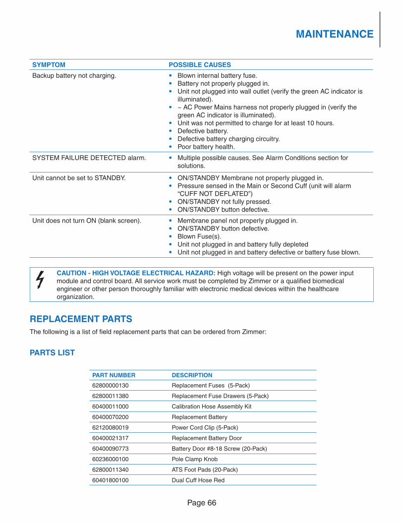
Page 66
MAINTENANCE
SYMPTOM POSSIBLE CAUSES
Backup battery not charging. • Blown internal battery fuse. • Battery not properly plugged in. • Unit not plugged into wall outlet (verify the green AC indicator is
illuminated). • ~ AC Power Mains harness not properly plugged in (verify the
green AC indicator is illuminated). • Unit was not permitted to charge for at least 10 hours. • Defective battery. • Defective battery charging circuitry. • Poor battery health.
SYSTEM FAILURE DETECTED alarm. • Multiple possible causes. See Alarm Conditions section for solutions.
Unit cannot be set to STANDBY. • ON/STANDBY Membrane not properly plugged in. • Pressure sensed in the Main or Second Cuff (unit will alarm
“CUFF NOT DEFLATED”) • ON/STANDBY not fully pressed. • ON/STANDBY button defective.
Unit does not turn ON (blank screen). • Membrane panel not properly plugged in. • ON/STANDBY button defective. • Blown Fuse(s). • Unit not plugged in and battery fully depleted • Unit not plugged in and battery defective or battery fuse blown.
CAUTION - HIGH VOLTAGE ELECTRICAL HAZARD: High voltage will be present on the power input module and control board. All service work must be completed by Zimmer or a qualifi ed biomedical engineer or other person thoroughly familiar with electronic medical devices within the healthcare organization.
REPLACEMENT PARTS
The following is a list of fi eld replacement parts that can be ordered from Zimmer:
PARTS LIST
PART NUMBER DESCRIPTION
62800000130 Replacement Fuses (5-Pack)
62800011380 Replacement Fuse Drawers (5-Pack)
60400011000 Calibration Hose Assembly Kit
60400070200 Replacement Battery
62120080019 Power Cord Clip (5-Pack)
60400021317 Replacement Battery Door
60400090773 Battery Door #8-18 Screw (20-Pack)
60236000100 Pole Clamp Knob
62800011340 ATS Foot Pads (20-Pack)
60401800100 Dual Cuff Hose Red
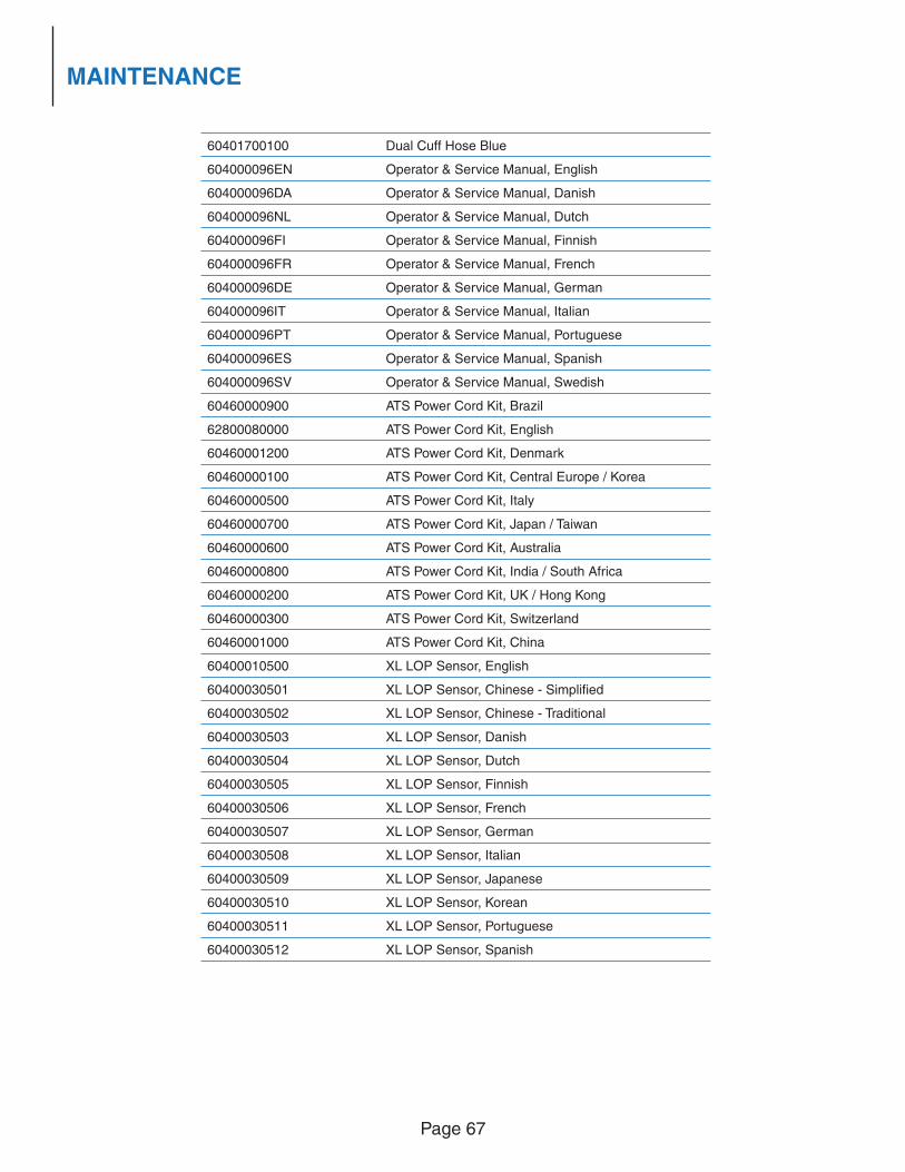
Page 67
MAINTENANCE
60401700100 Dual Cuff Hose Blue
604000096EN Operator & Service Manual, English
604000096DA Operator & Service Manual, Danish
604000096NL Operator & Service Manual, Dutch
604000096FI Operator & Service Manual, Finnish
604000096FR Operator & Service Manual, French
604000096DE Operator & Service Manual, German
604000096IT Operator & Service Manual, Italian
604000096PT Operator & Service Manual, Portuguese
604000096ES Operator & Service Manual, Spanish
604000096SV Operator & Service Manual, Swedish
60460000900 ATS Power Cord Kit, Brazil
62800080000 ATS Power Cord Kit, English
60460001200 ATS Power Cord Kit, Denmark
60460000100 ATS Power Cord Kit, Central Europe / Korea
60460000500 ATS Power Cord Kit, Italy
60460000700 ATS Power Cord Kit, Japan / Taiwan
60460000600 ATS Power Cord Kit, Australia
60460000800 ATS Power Cord Kit, India / South Africa
60460000200 ATS Power Cord Kit, UK / Hong Kong
60460000300 ATS Power Cord Kit, Switzerland
60460001000 ATS Power Cord Kit, China
60400010500 XL LOP Sensor, English
60400030501 XL LOP Sensor, Chinese - Simplifi ed
60400030502 XL LOP Sensor, Chinese - Traditional
60400030503 XL LOP Sensor, Danish
60400030504 XL LOP Sensor, Dutch
60400030505 XL LOP Sensor, Finnish
60400030506 XL LOP Sensor, French
60400030507 XL LOP Sensor, German
60400030508 XL LOP Sensor, Italian
60400030509 XL LOP Sensor, Japanese
60400030510 XL LOP Sensor, Korean
60400030511 XL LOP Sensor, Portuguese
60400030512 XL LOP Sensor, Spanish
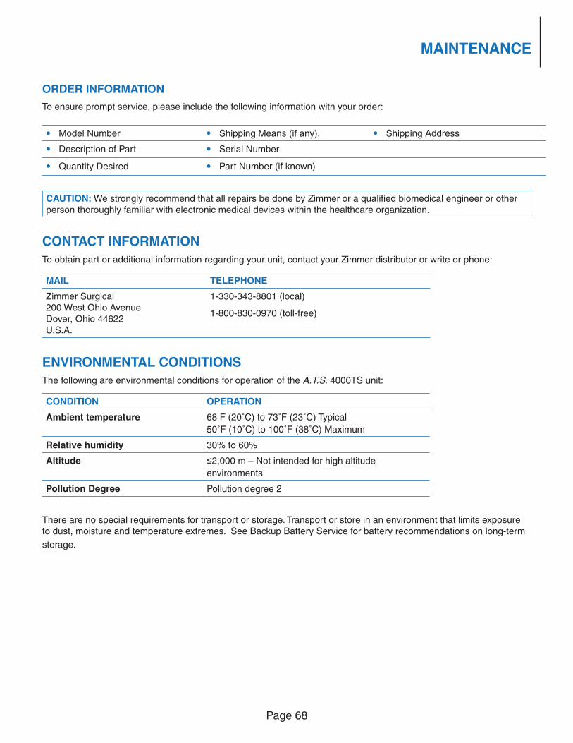
Page 68
MAINTENANCE
ORDER INFORMATION
To ensure prompt service, please include the following information with your order:
• Model Number • Shipping Means (if any). • Shipping Address
• Description of Part • Serial Number
• Quantity Desired • Part Number (if known)
CAUTION: We strongly recommend that all repairs be done by Zimmer or a qualifi ed biomedical engineer or other person thoroughly familiar with electronic medical devices within the healthcare organization.
CONTACT INFORMATION
To obtain part or additional information regarding your unit, contact your Zimmer distributor or write or phone:
MAIL TELEPHONE
Zimmer Surgical200 West Ohio AvenueDover, Ohio 44622U.S.A.
1-330-343-8801 (local)
1-800-830-0970 (toll-free)
ENVIRONMENTAL CONDITIONS
The following are environmental conditions for operation of the A.T.S. 4000TS unit:
CONDITION OPERATION
Ambient temperature 68 F (20˚C) to 73˚F (23˚C) Typical
50˚F (10˚C) to 100˚F (38˚C) Maximum
Relative humidity 30% to 60%
Altitude ≤2,000 m – Not intended for high altitude
environments
Pollution Degree Pollution degree 2
There are no special requirements for transport or storage. Transport or store in an environment that limits exposure to dust, moisture and temperature extremes. See Backup Battery Service for battery recommendations on long-term
storage.
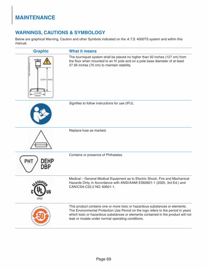
Page 69
MAINTENANCE
WARNINGS, CAUTIONS & SYMBOLOGY
Below are graphical Warning, Caution and other Symbols indicated on the A.T.S. 4000TS system and within this manual.
Graphic What it means
The tourniquet system shall be placed no higher than 50 inches (127 cm) from the fl oor when mounted to an IV pole and on a pole base diameter of at least 27.56 inches (70 cm) to maintain stability.
Signifi es to follow instructions for use (IFU).
Replace fuse as marked.
Contains or presence of Phthalates.
Medical – General Medical Equipment as to Electric Shock, Fire and Mechanical Hazards Only, in Accordance with ANSI/AAMI ES60601-1 (2005, 3rd Ed.) and CAN/CSA-C22.2 NO. 60601-1.
This product contains one or more toxic or hazardous substances or elements. The Environmental Protection Use Period on the logo refers to the period in years which toxic or hazardous substances or elements contained in the product will not leak or mutate under normal operating conditions.
DEHPDBP
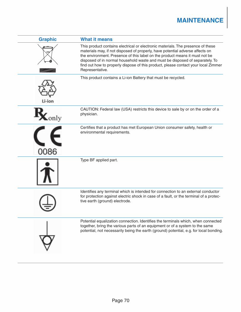
Page 70
MAINTENANCE
Graphic What it means
This product contains electrical or electronic materials. The presence of these materials may, if not disposed of properly, have potential adverse affects on the environment. Presence of this label on the product means it must not be disposed of in normal household waste and must be disposed of separately. To fi nd out how to properly dispose of this product, please contact your local Zimmer Representative.
This product contains a Li-ion Battery that must be recycled.
CAUTION: Federal law (USA) restricts this device to sale by or on the order of a physician.
Certifi es that a product has met European Union consumer safety, health or environmental requirements.
Type BF applied part.
Identifi es any terminal which is intended for connection to an external conductor for protection against electric shock in case of a fault, or the terminal of a protec-tive earth (ground) electrode.
Potential equalization connection. Identifi es the terminals which, when connected together, bring the various parts of an equipment or of a system to the same potential, not necessarily being the earth (ground) potential, e.g. for local bonding.
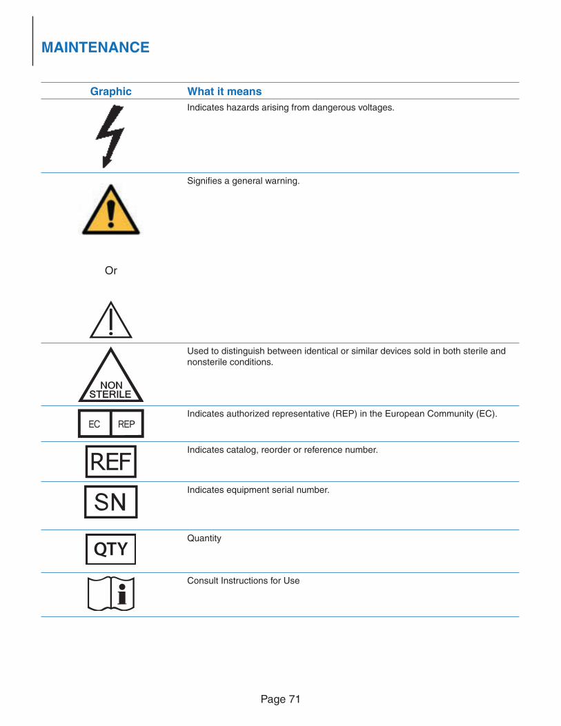
Page 71
MAINTENANCE
Graphic What it means
Indicates hazards arising from dangerous voltages.
Or
Signifi es a general warning.
Used to distinguish between identical or similar devices sold in both sterile and nonsterile conditions.
Indicates authorized representative (REP) in the European Community (EC).
Indicates catalog, reorder or reference number.
Indicates equipment serial number.
QTYQuantity
Consult Instructions for Use
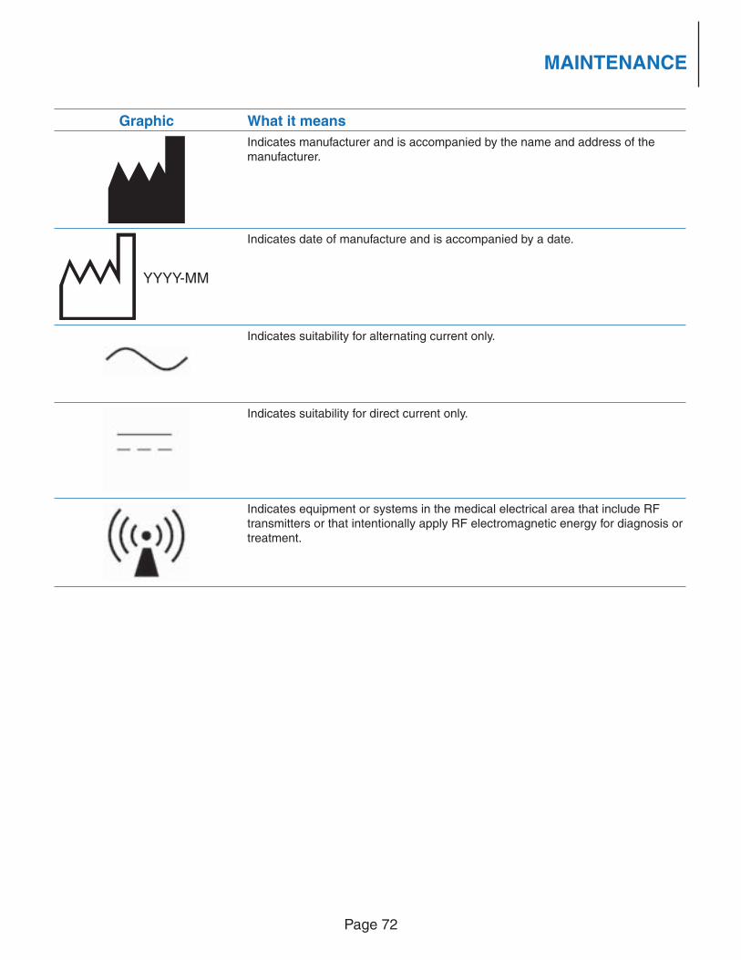
Page 72
MAINTENANCE
Graphic What it means
Indicates manufacturer and is accompanied by the name and address of the manufacturer.
Indicates date of manufacture and is accompanied by a date.
Indicates suitability for alternating current only.
Indicates suitability for direct current only.
Indicates equipment or systems in the medical electrical area that include RF transmitters or that intentionally apply RF electromagnetic energy for diagnosis or treatment.
YYYY-MM
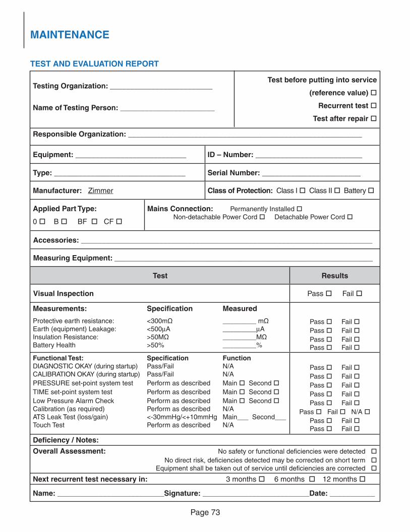
Page 73
MAINTENANCE
TEST AND EVALUATION REPORT
Defi ciency / Notes:
Overall Assessment:
No safety or functional defi ciencies were detected
No direct risk, defi ciencies detected may be corrected on short term Equipment shall be taken out of service until defi ciencies are corrected
Next recurrent test necessary in: 3 months 6 months 12 months
Name: __________________________Signature: __________________________Date: ___________
Testing Organization: _________________________
Name of Testing Person: _______________________
Test before putting into service
(reference value)
Recurrent test
Test after repair
Responsible Organization: _________________________________________________________
Equipment: ___________________________ ID – Number: __________________________
Type: ________________________________ Serial Number: ________________________
Manufacturer: Zimmer Class of Protection: Class I Class II Battery
Applied Part Type:
0 B BF CF
Mains Connection: Permanently Installed Non-detachable Power Cord Detachable Power Cord
Accessories: _______________________________________________________________________
Measuring Equipment: _______________________________________________________________
Measurements: Specifi cation Measured
Protective earth resistance: <300mΩ _________ mΩEarth (equipment) Leakage: <500μA _________μAInsulation Resistance: >50MΩ _________MΩBattery Health >50% _________%
Pass Fail
Pass Fail
Pass Fail Pass Fail
Functional Test: Specifi cation FunctionDIAGNOSTIC OKAY (during startup) Pass/Fail N/ACALIBRATION OKAY (during startup) Pass/Fail N/A
PRESSURE set-point system test Perform as described Main Second
TIME set-point system test Perform as described Main Second
Low Pressure Alarm Check Perform as described Main Second Calibration (as required) Perform as described N/AATS Leak Test (loss/gain) <-30mmHg/<+10mmHg Main___ Second___Touch Test Perform as described N/A
Pass Fail
Pass Fail
Pass Fail
Pass Fail
Pass Fail
Pass Fail N/A
Pass Fail Pass Fail
Test Results
Visual Inspection Pass Fail


Revision: B © 2013 Zimmer Surgical, Inc. Printed in U.S.A.622400048EN
Zimmer U.K. LTD.9 Lancaster PlaceSouth Marston ParkSwindon, Wiltshire SN3 4FPUnited Kingdom
0086
P
M Zimmer Surgical, Inc.200 West Ohio AvenueDover, Ohio 44622 U.S.A.