Embed Size (px)
DESCRIPTION
A/C Handling Manual
Citation preview
Bertrand Lattes Aviation Consult – B.L.A.C
13 Rue des Tourterelles, 34130 SAINT AUNES, France Tel : +33.(0).9.81.71.02.02
+33.(0).6.77.39.94.28 Mail: [email protected] Web site :
www.blaviationconsult.com
ATR 42-300
Aircraft Handling Manual
ATR 42-300
AIRCRAFT HANDLING MANUAL
TABLE OF CONTENT 1. General
1.1 List of aircraft
1.2 Exterior dimensions
1.3 Ground clearance
1.4 Weight and balance definitions
2. Aircraft limitations and features
2.1 Certificate limitations
2.1.1 Aircraft gross weight limitations
2.1.2 Performance operating weight
2.2 Standardized
3. Aircraft servicing
4. Loading
5. Form

Bertrand Lattes Aviation Consult – B.L.A.C
13 Rue des Tourterelles, 34130 SAINT AUNES, France Tel : +33.(0).9.81.71.02.02
+33.(0).6.77.39.94.28 Mail: [email protected] Web site :
www.blaviationconsult.com
ATR 42-300
AIRCRAFT HANDLING MANUAL GENERAL
1 GENERAL
1.1 LIST OF AIRCRAFT
This manual is effective for the following aircraft
Model Registration number Configuration
ATR 42
LY-ETM Cargo

Bertrand Lattes Aviation Consult – B.L.A.C
13 Rue des Tourterelles, 34130 SAINT AUNES, France Tel : +33.(0).9.81.71.02.02
+33.(0).6.77.39.94.28 Mail: [email protected] Web site :
www.blaviationconsult.com
ATR 42-300
AIRCRAFT HANDLING MANUAL GENERAL
1.2 WEIGHT AND BALANCE DEFINITION
1 BASIC WEIGHT : Aircraft weight including the furnishing
fixed equipment.
2 DRY OPERATING WEIGHT : Basic weight plus crew. Operational items
(DOW) (such as ballast fuel, stretcher …, if applied).
3 DEADLOAD : Gross weight of the cargo, mail, baggage
and empty ULDs.
4 OPERATING WEIGHT : Dry operating weight plus take off fuel.
5 PAYLOAD : Weight of the cargo, mail and ULDs (these
may be revenue and/or nonrevenue).
6 ZERO FUEL WEIGHT (ZFW) : Dry operating weight plus payload.
7 TAKE OFF WEIGHT : Zero fuel weight plus take off fuel.
(TOW)
8 DEADLOAD WEIGHT : Zero fuel weight
(DLW)
9 MAXIMUM TAKE OFF : Maximum weight at brake release as limited
WEIGHT (MTOW) by aircraft (MTOW) strength and airworthiness
requirements.
10 MAXIMUM ZERO FUEL : Maximum weight for landing as limited by
WEIGHT (MZFW) aircraft (MLDW) strength and airworthiness
requirements.
11 MAXIMUM ZERO FUEL : Maximum weight allowed before usable fuel
WEIGHT (MZFW) must be (MZFW) loaded in the aircraft as limited by
strength and airworthiness requirements.
12 MAXIMUM TAXI WEIGHT : Maximum weight for ground maneuver as
(MTW) limited by (MTW) aircraft strength and airworthiness
requirements. (It includes weight of taxi fuel)
13 CG : Center of gravity.
14 BA : Balance arms which are a true measure in
inches from the reference datum

Bertrand Lattes Aviation Consult – B.L.A.C
13 Rue des Tourterelles, 34130 SAINT AUNES, France Tel : +33.(0).9.81.71.02.02
+33.(0).6.77.39.94.28 Mail: [email protected] Web site :
www.blaviationconsult.com
ATR 42-300
AIRCRAFT HANDLING MANUAL GENERAL
15 %MAC (Percentage of Mean : The location of the aircraft CG relative to
Aerodynamic Chord) the leading edge of mean aerodynamic chord (MAC)
16 Index : The parameter used to express the variation
or location of CG which is the shortened moment of a
certain I weight
17 Basic index (BI) : The CG of aircraft basic weight expressed
with index
18 Dry Operating Index (DOI) : The CG of aircraft dry operating weight
expressed with index.
19 Laden Index Zero Fuel Weight : The CG of aircraft zero fuel weight
(LIZFW) expressed with (LIZFW) index.
20 Laden Index take off weight : The CG of aircraft take off weight expressed
with (LITOW) index.
21 Index of deadload weight (DLI) : The CG of aircraft dead load weight
expressed with (DLI) index
22 %MAC of Zero Fuel Weight : The CG of aircraft zero fuel weight
(MACZFW) expressed with % MAC
23 %MAC of take off weight : The CG of aircraft take off weight expressed
(MACTOW) with % MAC
24 %MAC of dead load weight : The CG of aircraft dead load weight
(MACDLW) expressed with %MAC
25 Take off fuel : The amount of fuel on board less the fuel
consumed before the take off run.
26 Taxi fuel : A standard quantity of fuel to cover engine
starts and ground maneuvers until start of take off,
APU consumption, the amount may be increased
when required by local conditions.
27 Trip fuel : Fuel required to fly from the airport of
departure to the planned destination, based on
“Planned Operating Conditions”. This amount shall
include fuel for take off, acceleration, climb, cruise,
descent, approach and landing.

Bertrand Lattes Aviation Consult – B.L.A.C
13 Rue des Tourterelles, 34130 SAINT AUNES, France Tel : +33.(0).9.81.71.02.02
+33.(0).6.77.39.94.28 Mail: [email protected] Web site :
www.blaviationconsult.com
ATR 42-300
AIRCRAFT HANDLING MANUAL GENERAL
28 Ballast fuel : The fuel in lieu of payload which is
specifically loaded for longitudinal balance control.
29 Usable fuel : Fuel available for aircraft propulsion.
30 Unusable fuel : Fuel can not be used to technical limitations
and must be included in weight and balance concerns.
ATR 42-300
AIRCRAFT HANDLING MANUAL AIRCRAFT LIMITATIONS & FEATURES
2 AIRCRAFT LIMITATIONS & FEATURES
2.1 CERTIFICATE LIMITATIONS
2.1.1 AIRCRAFT GROSS WEIGHT LIMITATIONS
Item
Maximum limitation
LY - ETM
Max. Taxi weight
Max. Zero fuel weight
Max. Take off weight
Max. Landing weight
17070
15540
16900
16400
2.1.2 PERFORMANCE OPERATING WEIGHT
To comply with the performance requirements of the aircraft manufacturer, the maximum allowable
take off and landing weights may be less than structural limits.
The maximum allowable weight for that flight that must not exceed the least of the following weights:
- Maximum allowable takeoff weight for the runway intended to be used (including corrections for
altitude and gradient, and wind and temperature conditions existing at the takeoff time).
- Maximum takeoff weight considering anticipated fuel and oil consumption that allows
compliance with applicable enroute performance limitations.
- Maximum take off weight considering anticipated fuel and oil consumption that allows
compliance with landing distance limitations or arrival at the destination and alternate airports.

Bertrand Lattes Aviation Consult – B.L.A.C
13 Rue des Tourterelles, 34130 SAINT AUNES, France Tel : +33.(0).9.81.71.02.02
+33.(0).6.77.39.94.28 Mail: [email protected] Web site :
www.blaviationconsult.com
ATR 42-300
AIRCRAFT HANDLING MANUAL AIRCRAFT LIMITATIONS & FEATURES
2.2 STANDARDIZED WEIGHT AND INDEX
CARGO KG INDEX A INDEX B INDEX C INDEX D INDEX E INDEX F FUEL
KG INDEX
0-50 -2 -1 0 1 2 3 0-600 1
51-100 -4 -2 0 2 4 6 601-1000 2
101-150 -6 -3 0 4 7 9 1001-1400 3
151-200 -8 -4 0 5 8 12 1401-1800 4
201-250 -11 -5 1 6 11 15 1801-2200 5
251-300 -13 -6 1 7 13 17 2201-2600 6
301-350 -15 -7 1 8 15 20 2601-3000 7
351-400 -17 -8 1 10 18 23 3001-3400 8
401-450 -19 -9 1 11 20 27 3401-3800 9
451-500 -21 -10 1 12 22 30 3801-4200 10
501-550 -23 -11 1 13 24 33 4201-4500 11
551-600 -25 -12 1 14 28 37
601-650 -27 -12 1 15 28 40
651-700 -30 -13 2 17 31 43
701-750 -32 -14 2 18 33 46
751-800 -34 -15 2 19 35 49
801-850 -36 -16 2 20 37 52
851-900 -38 -17 2 21 39 55
901-950 -40 -18 2 23 41 58
951-1000 -42 -19 2 24 43 61
1001-1050 -44 -20 2 25 45 64
1051-1100 -46 -21 3 26 47 67
1101-1150 -48 -21 3 27 49 70
1151-1200 -50 -21 3 28 51 73
1201-1250 -52 -21 3 29 53 76
1251-1300 -54 -21 4 30 55 79
1301-1350 57 81
1351-1400 59 84
1401-1450 87
1451-1500 90
A B C D E F
Max load 1270 kg Max load 1220 kg Max load 1220 kg Max load 1220 kg Max load 1400 kg Max load 1500 kg
Bertrand Lattes Aviation Consult – B.L.A.C
13 Rue des Tourterelles, 34130 SAINT AUNES, France Tel : +33.(0).9.81.71.02.02
+33.(0).6.77.39.94.28 Mail: [email protected] Web site :
www.blaviationconsult.com
ATR 42-300
AIRCRAFT HANDLING MANUAL AIRCRAFT LIMITATIONS & FEATURES
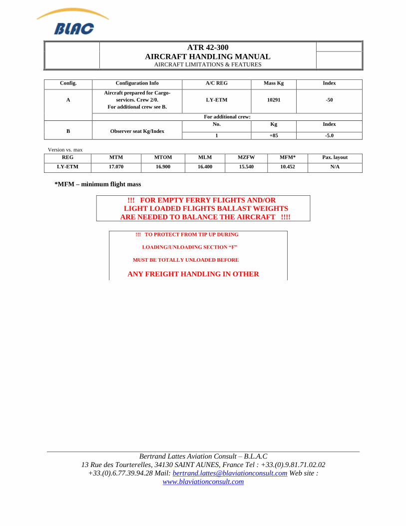
Config. Configuration Info A/C REG Mass Kg Index
A
Aircraft prepared for Cargo-
services. Crew 2/0.
For additional crew see B.
LY-ETM
10291
-50
For additional crew:
B
Observer seat Kg/Index
No. Kg Index
1 +85 -5.0
Version vs. max
REG MTM MTOM MLM MZFW MFM* Pax. layout
LY-ETM 17.070 16.900 16.400 15.540 10.452 N/A
*MFM – minimum flight mass
!!! FOR EMPTY FERRY FLIGHTS AND/OR
LIGHT LOADED FLIGHTS BALLAST WEIGHTS
ARE NEEDED TO BALANCE THE AIRCRAFT !!!!
!!! TO PROTECT FROM TIP UP DURING
LOADING/UNLOADING SECTION “F”
MUST BE TOTALLY UNLOADED BEFORE
ANY FREIGHT HANDLING IN OTHER
SECTIONS !!!

Bertrand Lattes Aviation Consult – B.L.A.C
13 Rue des Tourterelles, 34130 SAINT AUNES, France Tel : +33.(0).9.81.71.02.02
+33.(0).6.77.39.94.28 Mail: [email protected] Web site :
www.blaviationconsult.com
ATR 42-300
AIRCRAFT HANDLING MANUAL AIRCRAFT LIMITATIONS & FEATURES
2.3 STANDARDIZED WEIGHT PER CREW
Specification Standard weight
(KG)
Charter
flight Definition of age
Crew Cockpit crew
90 -

Bertrand Lattes Aviation Consult – B.L.A.C
13 Rue des Tourterelles, 34130 SAINT AUNES, France Tel : +33.(0).9.81.71.02.02
+33.(0).6.77.39.94.28 Mail: [email protected] Web site :
www.blaviationconsult.com
2.4 LAST MINUTE CHANGE
The LMC tolerance is ± 300 kg. If exceeded, a new loadsheet is required.
The following must be checked:
a. Traffic load only:
- The LMC positive total weight is lower than the underload before LMC.
- No loading limitation exceeded.
- The balance at MACZFW and MACTOW remains within the allowed limits.
- All the LMC data on the loadsheet is completed.
b. Useable fuel only:
- Issue the new loadsheet when change in fuel figures
ATR 42-300
AIRCRAFT HANDLING MANUAL AIRCRAFT SERVICING
3. AIRCRAFT SERVICING
3.1 ARRANGEMENT OF GROUND HANDLING EQUIPMENT
This diagram shows an example of the arrangement of ground handling equipment for the ATR 42-
300 aircraft:

Bertrand Lattes Aviation Consult – B.L.A.C
13 Rue des Tourterelles, 34130 SAINT AUNES, France Tel : +33.(0).9.81.71.02.02
+33.(0).6.77.39.94.28 Mail: [email protected] Web site :
www.blaviationconsult.com
ATR 42-300
AIRCRAFT HANDLING MANUAL AIRCRAFT SERVICING
3.2 SERVICING POINTS
This diagram shows the locations of the servicing points of the ATR 42-300 aircraft from a top view:
NOTE : A: Air conditioning
E: Electrical
F: Fuel
H: Hydraulic
O: Oil Engine

Bertrand Lattes Aviation Consult – B.L.A.C
13 Rue des Tourterelles, 34130 SAINT AUNES, France Tel : +33.(0).9.81.71.02.02
+33.(0).6.77.39.94.28 Mail: [email protected] Web site :
www.blaviationconsult.com
ATR 42-300
AIRCRAFT HANDLING MANUAL AIRCRAFT SERVICING
3.3 EXTERNAL POWER
The DC and ACW electrical distribution system can be supplied from ground power sources,
connected via the separate “External Power” receptacles which are located on the lower right side of the
fuselage, just aft of the nose gear.
The specification of the DC GPU for ATR 42 requires the ground unit to be able to provide a steady
current of 300 to 400 Amp under 28 volts to insure correct functioning of all electrical services prior to
startup.
For engine start, the GPU must be able to provide ADDITIONNAL STARTER CURRENT of
1000Amp while keeping more than 12 volts (ie 16 KW instantaneous power).
CAUTION : If DC EXT PWR voltage on maintenance panel still shows less than 26 v despite the full
load load shedding, the GPU MUST BE CONSIDERED AS COMPLETELY
UNUSABLE.
If DC EXT PWR voltage on maintenance panel is above 26 v, the DC GPU may be
used to maintain aircraft batteries charge whilst using all other ground services
normally (cargo door, refueling, cabin lighting, etc…)
WARNINGS : Do not disconnect external power while the GPU is supplying power to the aircraft.
Failure to obey this may cause serious burn injuries and blindness to personnel, and
severe damage to the external power receptacle and GPU power cable connector.
If the external power earth grounded neutral is open, the aircraft will have an
electrical potential above earth ground, which may cause an electric shock with
possible serious injuries to personnel touching the aircraft. If an electric arc is
observed when touching the aircraft, make sure that all personnel are kept clear of
the aircraft and contact maintenance, or the commander immediately.
Bertrand Lattes Aviation Consult – B.L.A.C
13 Rue des Tourterelles, 34130 SAINT AUNES, France Tel : +33.(0).9.81.71.02.02
+33.(0).6.77.39.94.28 Mail: [email protected] Web site :
www.blaviationconsult.com
ATR 42-300
AIRCRAFT HANDLING MANUAL AIRCRAFT SERVICING
CAUTIONS : When using a mobile GPU, check voltage and frequency to be within limits. Voltage
below or above specified limits may cause damage to aircraft electrical equipment.
A mobile GPU must never be left connected to a tractor when the GPU power cable
is connected to an aircraft. This to avoid damage to the GPU and/or the aircraft if the
tractor is moved.
When using a combustion engine driven GPU, make sure a hand fire extinguisher of
suitable size and type is mounted externally on the GPU, or is available in close
vicinity to the GPU. The fire extinguisher shall be sealed and date labeled.
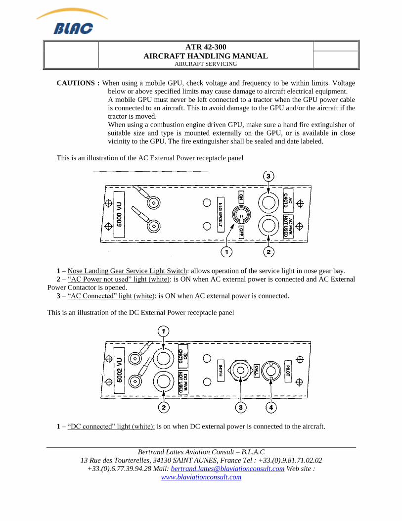
This is an illustration of the AC External Power receptacle panel
1 – Nose Landing Gear Service Light Switch: allows operation of the service light in nose gear bay.
2 – “AC Power not used” light (white): is ON when AC external power is connected and AC External
Power Contactor is opened.
3 – “AC Connected” light (white): is ON when AC external power is connected.
This is an illustration of the DC External Power receptacle panel
1 – “DC connected” light (white): is on when DC external power is connected to the aircraft.

Bertrand Lattes Aviation Consult – B.L.A.C
13 Rue des Tourterelles, 34130 SAINT AUNES, France Tel : +33.(0).9.81.71.02.02
+33.(0).6.77.39.94.28 Mail: [email protected] Web site :
www.blaviationconsult.com
ATR 42-300
AIRCRAFT HANDLING MANUAL AIRCRAFT SERVICING
2 – DC Power not used light (white): is on when DC external power is connected to the aircraft, and
DC external power contactor is opened.
3 – Interphone Jack: used by ground mechanic to connect a headset to communicate with crew.
4 – Pilot call button: when depressed, sends a call (aural and visual) to the cockpit: “Mechanic call”
light illuminates on the overhead panel.
The illustration below shows “MAIN ELEC PWR” panel.
1 – Battery toggle switch

Bertrand Lattes Aviation Consult – B.L.A.C
13 Rue des Tourterelles, 34130 SAINT AUNES, France Tel : +33.(0).9.81.71.02.02
+33.(0).6.77.39.94.28 Mail: [email protected] Web site :
www.blaviationconsult.com
1 – EXT PWR pushbutton:
AVAIL illuminates green when conditions of DC external power connection are met
ON allows to connect DC external power
ATR 42-300
AIRCRAFT HANDLING MANUAL AIRCRAFT SERVICING
3.3.1 CONNECTING EXTERNAL POWER, FLIGHT DECK MANNED
Before connecting external power, according to the procedure below, you must be aware of the
WARNINGS and CAUTIONS as described in 3.3 EXTERNAL POWER.
Follow these steps to connect external power to the aircraft:
Step Action
1 Make sure the GPU is switched off electrically.
2 Inspect the external power cable connector and cable for damage.
3 When the aircraft has come to a complete stop:
Open the external power access door
Connect the external power cable connector to the DC
external power receptacle
Make sure the cable connector is fully engaged.
4 Switch on the GPU electrically and check that:
The white “DC Connected” light comes on
3.3.2 DISCONNECTING EXTERNAL POWER, FLIGHT DECK MANNED
Before disconnecting external power, according to the procedure below, you must be aware of the
WARNINGS and CAUTIONS as described in 3.3 EXTERNAL POWER.
Follow these steps to disconnect external power from the aircraft:
Step Action
1 Make sure the white “DC PWR NOT USED” light is on.
2 Switch off the GPU electrically and check that:
The “DC CNCTD” light is out.
3 Disconnect the external power cable connector.
4 Close the DC external power access door.
5 Stow the external power cable and connector on the GPU
6 Shut down the GPU (when applicable).

Bertrand Lattes Aviation Consult – B.L.A.C
13 Rue des Tourterelles, 34130 SAINT AUNES, France Tel : +33.(0).9.81.71.02.02
+33.(0).6.77.39.94.28 Mail: [email protected] Web site :
www.blaviationconsult.com
ATR 42-300
AIRCRAFT HANDLING MANUAL AIRCRAFT SERVICING
3.3.3 CONNECTING EXTERNAL POWER, FLIGHT DECK UNMANNED
Before connecting external power, according to the procedure below, you must be aware of the
WARNINGS and CAUTIONS as described in 3.3 EXTERNAL POWER.
Follow these steps to connect external power to the aircraft:
Externally. Steps 1 – 4 are performed externally
Step Action
1 Make sure the GPU is switched off electrically.
2 Inspect the external power cable connector and cable for damage.
3 Check that the aircraft is properly chocked and:
Open the DC external power access door
Connect the external power cable connector to the DC external
power receptacle
Make sure the cable connector is fully engaged.
4 Switch on the GPU electrically and check that:
The white “DC Connected” light comes on
Flight deck. Steps 5 to 7 is performed on the flight deck
5 Check that the green “EXT PWR AVAIL” light is on.
If neither light is on, call maintenance or the Commander for assistance.
6 Place the “BAT” toggle switch in the “ON” position
7 Push the “EXT PWR” pushbutton and check that the switch-light comes
on.
3.3.4 DISCONNECTING EXTERNAL POWER, FLIGHT DECK UNMANNED
Before disconnecting external power, according to the procedure below, you must be aware of the
WARNINGS and CAUTIONS as described in 3.3 EXTERNAL POWER.
Follow these steps to disconnect external power from the aircraft:
Flight deck. Steps 1-3 are performed on the flight deck
Step Action
1 Push the “EXT PWR” pushbutton and check that the switch-light
goes off.
2 Check that the red “INV FAULT” light is on.
3 Place the “BAT” toggle switch in the “OFF” position and check that
“EXT PWR” pushbutton illuminates green “AVAIL” light.
Externally. Steps 4 to 8` are performed externally
4 Switch off the GPU electrically and check that:
The white “DC CNCTD” light is out.
5 Disconnect the external power cable connector.
6 Close the DC external power access door
7 Stow the external power cable and cable connector on the GPU.
8 Shut down the GPU (when applicable).

Bertrand Lattes Aviation Consult – B.L.A.C
13 Rue des Tourterelles, 34130 SAINT AUNES, France Tel : +33.(0).9.81.71.02.02
+33.(0).6.77.39.94.28 Mail: [email protected] Web site :
www.blaviationconsult.com
ATR 42-300
AIRCRAFT HANDLING MANUAL AIRCRAFT SERVICING
3.5 AIRCRAFT DOORS
3.5.1 REAR DOOR (left side)
Rear door is an outward opening, non plug type door with a net opening of 64 cm (25 in) wide
(without hand-rail(s)) and 1.73 m (68 in) high.
The mechanism is essentially composed of a handle, a lifting cam and one locking shoot bolt placed
on the rear part of the door.
The door mechanism is driven by an external handle allowing the door to be operated from outside
only of the aircraft.

Bertrand Lattes Aviation Consult – B.L.A.C
13 Rue des Tourterelles, 34130 SAINT AUNES, France Tel : +33.(0).9.81.71.02.02
+33.(0).6.77.39.94.28 Mail: [email protected] Web site :
www.blaviationconsult.com
ATR 42-300
AIRCRAFT HANDLING MANUAL AIRCRAFT SERVICING
3.5.2 CREW ENTRY DOOR
The Crew Entry door is located on the left side of the fuselage and it is embedded in the Large Cargo
Door. The Crew Entry door is outward opening non plug type door with a net opening of 944 mm (24 in)
wide and 1889 mm (48 in) high. The Crew Entry door has two hinges on the fore edge and it is latched by
five shoot bolts which are locked by two latch-locks. A pressure vent door is operated simultaneously
with the latch-locks. The door mechanism is driven by both internal and external handles allowing the
door to be operated from inside or outside of the aircraft. The door is equipped with a hold-open device
that engages the external handle when the door is open. Two microswitches installed on the surround at
shoot bolt locations and one microswitch installed on the door at latch-lock location provide a signal
alerting, if the door is not fully latched and locked.
Bertrand Lattes Aviation Consult – B.L.A.C
13 Rue des Tourterelles, 34130 SAINT AUNES, France Tel : +33.(0).9.81.71.02.02
+33.(0).6.77.39.94.28 Mail: [email protected] Web site :
www.blaviationconsult.com
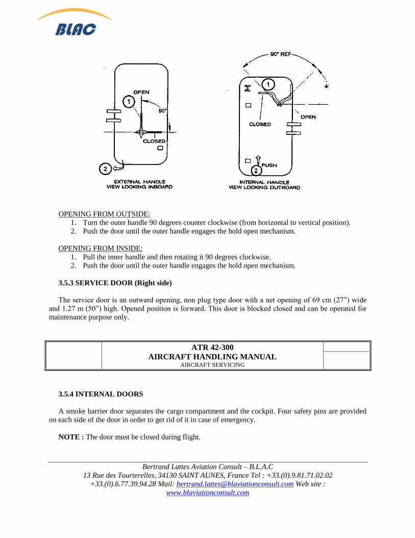
OPENING FROM OUTSIDE:
1. Turn the outer handle 90 degrees counter clockwise (from horizontal to vertical position).
2. Push the door until the outer handle engages the hold open mechanism.
OPENING FROM INSIDE:
1. Pull the inner handle and then rotating it 90 degrees clockwise.
2. Push the door until the outer handle engages the hold open mechanism.
3.5.3 SERVICE DOOR (Right side)
The service door is an outward opening, non plug type door with a net opening of 69 cm (27”) wide
and 1.27 m (50”) high. Opened position is forward. This door is blocked closed and can be operated for
maintenance purpose only.
ATR 42-300
AIRCRAFT HANDLING MANUAL AIRCRAFT SERVICING
3.5.4 INTERNAL DOORS
A smoke barrier door separates the cargo compartment and the cockpit. Four safety pins are provided
on each side of the door in order to get rid of it in case of emergency.
NOTE : The door must be closed during flight.

Bertrand Lattes Aviation Consult – B.L.A.C
13 Rue des Tourterelles, 34130 SAINT AUNES, France Tel : +33.(0).9.81.71.02.02
+33.(0).6.77.39.94.28 Mail: [email protected] Web site :
www.blaviationconsult.com
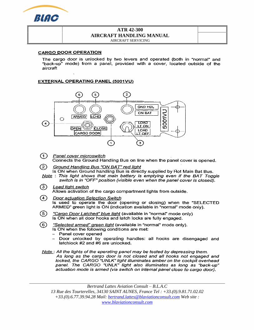
3.5.5 LARGE CARGO DOOR
The large cargo door is an outward opening, non plug type door hinged at its upper edge giving a net
clear opening of 2946 mm (116 in) wide by 1803 mm (71 in) high and with a max opening angle of 110°.
Door actuation system is
hydraulically powered and electrically
controlled (see schematic: P1F/1G).
Two operating modes are available:
Normal : operation through control
devices and indications provided on
the external panel (access to controls
into cockpit not required).
Back-up : when normal mode not
available, back-up function can be
armed through a switch on internal
panel. Then door is operated via
external panel controls (indications are
not available in back-up mode).
External marking close to the door
and panel reports instructions and
“caution” information for the operator.
See schematic P 1H.
A hold-open strut maintains the
cargo door in the opened position. It
also protects the door from wind gusts.
The hold open strut should be used
anytime the door is in the open
position.
Bertrand Lattes Aviation Consult – B.L.A.C
13 Rue des Tourterelles, 34130 SAINT AUNES, France Tel : +33.(0).9.81.71.02.02
+33.(0).6.77.39.94.28 Mail: [email protected] Web site :
www.blaviationconsult.com
ATR 42-300
AIRCRAFT HANDLING MANUAL AIRCRAFT SERVICING

Bertrand Lattes Aviation Consult – B.L.A.C
13 Rue des Tourterelles, 34130 SAINT AUNES, France Tel : +33.(0).9.81.71.02.02
+33.(0).6.77.39.94.28 Mail: [email protected] Web site :
www.blaviationconsult.com
ATR 42-300
AIRCRAFT HANDLING MANUAL AIRCRAFT SERVICING

Bertrand Lattes Aviation Consult – B.L.A.C
13 Rue des Tourterelles, 34130 SAINT AUNES, France Tel : +33.(0).9.81.71.02.02
+33.(0).6.77.39.94.28 Mail: [email protected] Web site :
www.blaviationconsult.com
ATR 42-300
AIRCRAFT HANDLING MANUAL LOADING
4. LOADING
4.1 CARGO COMPARTMENT
The cargo compartment extends from the cockpit partition 45.44 feet to the aft pressure bulkhead. The
cargo compartment is designed to load one 88 inch wide by 54 inch pallet and three 88 inch wide by 108
inch long pallets with a maximum localized load height of 64 inches and a maximum pallet side height of
55.11 inches. Bulk freight may also be loaded behind the designated pallet area or in the absence of any
pallet(s). The compartment floor structure is capable of supporting 408 pounds per foot and all floor
panels are capable of carrying a surface distributed load of 82 pounds per square foot without appreciable
deformation, while also bearing a local indentation load of 1,310 pounds per square inch without any
panel core crushing.

Bertrand Lattes Aviation Consult – B.L.A.C
13 Rue des Tourterelles, 34130 SAINT AUNES, France Tel : +33.(0).9.81.71.02.02
+33.(0).6.77.39.94.28 Mail: [email protected] Web site :
www.blaviationconsult.com
ATR 42-300
AIRCRAFT HANDLING MANUAL LOADING
4.2 CARGO COMPARTMENT SPECIFICATIONS
1. Cargo Compartment
Height………………………………………………………………………………….68.9”
Width (floor)……………………………………………………………..………………89”
Length…………………………………………………………………...……………45.44”
Overall Usable Cargo Volume……………………………………….……..1,533cubic feet
Maximum Floor loading………………………………….……81.9 pounds per square foot
2. Door Openings
Large Cargo Door……………………………………………………….116.00” x 71.00”
Rear Door………………………………………………………………………..27” x 50”
4.3 CARGO COMPARTMENT LIMITS
LD3………………………………………………………………...………………2645.00 Lbs
88” x 108” Pallet…………………………………………………………………..3,637.62 Lbs
88” x 54” Pallet………………………………………………………….…………1818.00 Lbs
Forward Crash Net…………………………………………………………...…..19,290.45 Lbs
Forward Transverse Crash Net…………………………………………………….3,086.47 Lbs
Intermediate Transverse Crash Net……………………………………..…………3,527.39 Lbs
WARNING: Good judgment must be used to position piercing or penetrating type cargo.
Load cargo of a piercing or penetrating nature at least 4¼ feet aft of compressible
cargo (density lower than 15.6 lb/cu. feet) To prevent penetration through the
crash nets (forward crash net, forward transverse crash net, intermediate
transverse crash net) when subject to a 9G forward load.

Bertrand Lattes Aviation Consult – B.L.A.C
13 Rue des Tourterelles, 34130 SAINT AUNES, France Tel : +33.(0).9.81.71.02.02
+33.(0).6.77.39.94.28 Mail: [email protected] Web site :
www.blaviationconsult.com
Always load at least 4¼ feet of compressible cargo (density lower than 15.6
lb/cu. feet) between a crash net (forward crash net, forward transverse crash net,
intermediate transverse crash net) and incompressible cargo (density higher than
15.6 lb/cu. feet), when the net precedes the incompressible cargo.
When it is necessary to install the forward transverse crash net at its forward limit
(STA 6620), port and starboard attachment points must be translated for the same
length respect to the forward limit.
ATR 42-300
AIRCRAFT HANDLING MANUAL LOADING
4.4 PACKAGE SIZE DIMENSIONS
The maximum dimensions of the package which can be loaded in cargo compartment are given in
following tables. Dimensions are given in centimeters.
NOTE : Lengths are determined for packages in full contact with compartment
floor during loading operations and storage. Tilting, twisting, bending and/or
rotating packages through door opening will allow additional lengths in most
cases, but these should be determined for each special situation depending on
allowable conditions.

Bertrand Lattes Aviation Consult – B.L.A.C
13 Rue des Tourterelles, 34130 SAINT AUNES, France Tel : +33.(0).9.81.71.02.02
+33.(0).6.77.39.94.28 Mail: [email protected] Web site :
www.blaviationconsult.com
Cargo Compartment (Large Cargo Door):

Bertrand Lattes Aviation Consult – B.L.A.C
13 Rue des Tourterelles, 34130 SAINT AUNES, France Tel : +33.(0).9.81.71.02.02
+33.(0).6.77.39.94.28 Mail: [email protected] Web site :
www.blaviationconsult.com
ATR 42-300
AIRCRAFT HANDLING MANUAL LOADING
4.5 CARGO COMPARTMENT FLOOR CAPABILITY
The dimensions, maximum available, width and height for the loads are presented in the figure 4.1.
Figure 4.1

Bertrand Lattes Aviation Consult – B.L.A.C
13 Rue des Tourterelles, 34130 SAINT AUNES, France Tel : +33.(0).9.81.71.02.02
+33.(0).6.77.39.94.28 Mail: [email protected] Web site :
www.blaviationconsult.com
ATR 42-300
AIRCRAFT HANDLING MANUAL LOADING
4.6 LOADING PRECAUTIONS
The ATR 42-300 has a “nose heavy” tendency. Because of this, no tail stand is provided for this
aircraft. For the ATR 42-300 to tip on its tail during ground loading, the aircraft would have to reach 63%
MAC. To protect it from tip up, stations 17319 and 19557 (compartment F), must be loaded last and
completely unloaded first during any loading/unloading operation.
For empty ferry flights and/or light loaded flights, ballast weights will be needed to balance the
aircraft.
Freight shall never be loaded above the “water mark” or red line painted in the cargo compartment of
the ATR. This water mark is located at 64 inches above the floor and provides adequate clearance for the
smoke detectors and lights to function.
It is prohibited to carry freight between the forward 9G crash net and the cockpit partition.
Cargo of a piercing or penetrating nature must be loaded at least 4¼ feet aft of compressible cargo
(density lower than 15.6 lb/cu. ft) to prevent penetration through the crash nets. This precaution must be
exercised for each crash net used in the loading process
4.7 RESTRAINT REQUIREMENTS
ATR 42-300 cargo must be restrained to prevent for the following ULTIMATE directional loads:
Direction Gravitational Units “G’s”
Forward
Up
Side (Left/Right)
9.00
3.00
3.00
Bertrand Lattes Aviation Consult – B.L.A.C
13 Rue des Tourterelles, 34130 SAINT AUNES, France Tel : +33.(0).9.81.71.02.02
+33.(0).6.77.39.94.28 Mail: [email protected] Web site :
www.blaviationconsult.com
ATR 42-300
AIRCRAFT HANDLING MANUAL LOADING
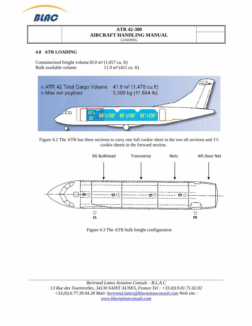
4.8 ATR LOADING
Containerized freight volume 30.0 m³ (1,057 cu. ft)
Bulk available volume 11.9 m³ (421 cu. ft)
Figure 4.2 The ATR has three sections to carry one full cookie sheet in the two aft sections and 1½
cookie sheets in the forward section.
Figure 4.3 The ATR bulk freight configuration
9G Bulkhead Transverse Nets Aft Door Net


![ATR 42-72 the Regional Way 2009-Light[1]](https://img.pdfslide.us/doc/110x75/5511ba5e4a7959d2028b4754/atr-42-72-the-regional-way-2009-light1.jpg)