Embed Size (px)
Citation preview
ATPL
Operational Procedures
ATPL Operational Procedures 28 October 2003 ii
© Atlantic Flight Training All rights reserved. No part of this manual may be reproduced or transmitted in any forms by any means, electronic or mechanical, including photocopying, recording or by any information storage and retrieval system, without permission from Atlantic Flight Training in writing.
ATPL Operational Procedures ©Atlantic Flight Training iii
PART 1. ICAO ANNEX 6
CHAPTER 1
Definitions Introduction ........................................................................................................................................1-1 Terms.................................................................................................................................................1-1
CHAPTER 2
Operator’s Responsibilities Introduction ........................................................................................................................................2-1 Employees Abroad.............................................................................................................................2-1 Operating Pilots .................................................................................................................................2-1 Operational Control ............................................................................................................................2-1 Emergency Situations ........................................................................................................................2-2 Search and Rescue Operations .........................................................................................................2-2 Accident Prevention Programmes......................................................................................................2-2
CHAPTER 3
Flight Operations Operating facilities..............................................................................................................................3-1 Operational certification and supervision ...........................................................................................3-1 The air operator certificate (AOC) ......................................................................................................3-1 Operations manual.............................................................................................................................3-2 Operating instructions – general ........................................................................................................3-2 In-flight simulation of emergency situations .......................................................................................3-3 Checklists...........................................................................................................................................3-3 Minimum flight altitudes......................................................................................................................3-4 Aerodrome operating minima.............................................................................................................3-4 Threshold crossing height for precision approaches..........................................................................3-5 Crew flight time, flight duty periods and rest periods..........................................................................3-5 Passengers ........................................................................................................................................3-6 Flight preparation ...............................................................................................................................3-6 Operational flight planning .................................................................................................................3-7 Alternate aerodromes.........................................................................................................................3-7 Weather conditions ............................................................................................................................3-8 Fuel and oil supply .............................................................................................................................3-8 Refuelling with passengers on board ...............................................................................................3-10 Oxygen supply .................................................................................................................................3-11 Use of oxygen ..................................................................................................................................3-12 Safeguarding of cabin attendants and passengers in pressurized aeroplanes in the event of loss of pressurization...................................................................................................................................3-12 In-flight procedures ..........................................................................................................................3-12 Aerodrome operating minima...........................................................................................................3-12 Hazardous flight conditions ..............................................................................................................3-12 Flight crew members at duty stations...............................................................................................3-13 Seat belts .........................................................................................................................................3-13 Safety harness .................................................................................................................................3-13 In-flight operational instructions .......................................................................................................3-13 Instrument flight procedures.............................................................................................................3-13 Duties of pilot-in-command ..............................................................................................................3-14 Duties of flight operations officer/flight dispatcher............................................................................3-14
ATPL Operational Procedures 28 October 2003 iv
Additional requirements for extended range operations by aeroplanes with two turbine power-units (ETOPS) ..........................................................................................................................................3-14 Carry-on baggage ............................................................................................................................3-15
CHAPTER 4
Aeroplane Performance Operating Limitations General ..............................................................................................................................................4-1 Application .........................................................................................................................................4-1 Mass limitations .................................................................................................................................4-2 Take-off..............................................................................................................................................4-3 En route - one power-unit inoperative ................................................................................................4-3 En route - two power-units inoperative...............................................................................................4-3 Landing ..............................................................................................................................................4-3
CHAPTER 5
Aeroplane Instruments, Equipment and Flight Documents General ..............................................................................................................................................5-1 All aeroplanes on all flights ................................................................................................................5-1 Marking of break-in points..................................................................................................................5-3 Flight recorders ..................................................................................................................................5-3 Flight data recorders – types..............................................................................................................5-4 Flight data recorders – duration .........................................................................................................5-4 Flight data recorder requirements ......................................................................................................5-5 Cockpit voice recorder (CVR) ............................................................................................................5-5 Cockpit voice recorder requirements..................................................................................................5-6 Cockpit voice recorders – duration.....................................................................................................5-6 Flight recorders – construction and installation ..................................................................................5-6 Flight recorders – operation ...............................................................................................................5-6 Flight recorders – continued serviceability .........................................................................................5-7 FDR and CVR – General requirements..............................................................................................5-7 Parameters for FDR recording ...........................................................................................................5-8 All aeroplanes operated as VFR flights ..............................................................................................5-9 All aeroplanes on flights over water ...................................................................................................5-9 All aeroplanes on long range over-water flights ...............................................................................5-10 All aeroplanes on flights over designated land areas.......................................................................5-10 All aeroplanes on high altitude flights...............................................................................................5-10 All aeroplanes in icing conditions .....................................................................................................5-11 All aeroplanes operated in accordance with instrument flight rules..................................................5-11 All aeroplanes over 5700 kg – Emergency power supply for electrically operated attitude indicating instruments ......................................................................................................................................5-12 All aeroplanes when operated at night .............................................................................................5-12 Pressurized aeroplanes when carrying passengers – weather radar...............................................5-12 All aeroplanes operated above 15 000 m (49 000 ft) – radiation indicator .......................................5-13 All aeroplanes complying with the noise certification Standards in Annex 16, Volume I ..................5-13 Mach number indicator.....................................................................................................................5-13 Aeroplanes required to be equipped with ground proximity warning systems (GPWS) ...................5-13 Aeroplanes carrying passengers – cabin attendants’ seats .............................................................5-14 Emergency locator transmitter (ELT) ...............................................................................................5-14 Aeroplanes required to be equipped with an airborne collision avoidance system (ACAS II) ..........5-15 Aeroplanes required to be equipped with a pressure-altitude reporting transponder .......................5-15 Microphones ....................................................................................................................................5-15 Turbo-jet aeroplanes - forward-looking wind shear warning system ................................................5-15 Master Minimum Equipment List (MMEL) ........................................................................................5-15 Minimum Equipment List (MEL) .......................................................................................................5-16
ATPL Operational Procedures ©Atlantic Flight Training v
CHAPTER 6
Aeroplane Communication and Navigation Equipment Communication equipment ................................................................................................................6-1 Navigation equipment ........................................................................................................................6-1 Redundancy.......................................................................................................................................6-2 Installation..........................................................................................................................................6-2
CHAPTER 7
Aeroplane Maintenance Definition ............................................................................................................................................7-1 Operator’s maintenance responsibilities ............................................................................................7-1 Operator’s maintenance control manual ............................................................................................7-1 Maintenance programme ...................................................................................................................7-2 Maintenance records..........................................................................................................................7-2 Continuing airworthiness information .................................................................................................7-2 Modifications and repairs ...................................................................................................................7-3 Approved maintenance organization..................................................................................................7-3 Issue of approval................................................................................................................................7-3 Maintenance organization’s procedures manual................................................................................7-3 Maintenance procedures and quality assurance system....................................................................7-3 Facilities .............................................................................................................................................7-4 Personnel...........................................................................................................................................7-4 Records..............................................................................................................................................7-4 Maintenance release..........................................................................................................................7-4
CHAPTER 8
Aeroplane Flight Crew Composition of the flight crew ............................................................................................................8-1 Radio operator ...................................................................................................................................8-1 Flight engineer ...................................................................................................................................8-1 Flight navigator ..................................................................................................................................8-1 Flight crew member emergency duties ..............................................................................................8-1 Flight crew member training programmes..........................................................................................8-2 Qualifications .....................................................................................................................................8-2 Recent experience - pilot-in-command...............................................................................................8-2 Recent experience - co-pilot ..............................................................................................................8-2 Pilot-in-command - route and airport qualification..............................................................................8-3 Nomination as Commander ...............................................................................................................8-4 Pilot proficiency checks......................................................................................................................8-4 Flight crew equipment ........................................................................................................................8-4 Flight time, flight duty periods and rest periods..................................................................................8-4
CHAPTER 9
Manuals, Logs and Records Flight manual .....................................................................................................................................9-1 Journey log book................................................................................................................................9-1 Operations Manual.............................................................................................................................9-1 Records of emergency and survival equipment carried .....................................................................9-5

ATPL Operational Procedures 28 October 2003 vi
CHAPTER 10
Security Security of the flight crew compartment ...........................................................................................10-1 Aeroplane search procedure checklist .............................................................................................10-1 Training programmes.......................................................................................................................10-1 Reporting acts of unlawful interference............................................................................................10-1
ATPL Operational Procedures ©Atlantic Flight Training vii
PART 2. JAR-OPS 1
CHAPTER 11
General Requirements Introduction ......................................................................................................................................11-1 JAR-OPS 1.035 - Quality System ....................................................................................................11-1 JAR-OPS 1.037 - Accident Prevention and Flight Safety Programme .............................................11-1 JAR-OPS 1.040 - Additional Crew Members ...................................................................................11-1 JAR-OPS 1.075 - Method of Carriage of Persons............................................................................11-1 JAR-OPS 1.085 - Crew Responsibilities ..........................................................................................11-2 JAR-OPS 1.100 - Admission to Flight Deck .....................................................................................11-3 JAR-OPS 1.110 - Portable Electronic Devices.................................................................................11-4 JAR-OPS 1.115 - Alcohol and Drugs ...............................................................................................11-4 JAR-OPS 1.120 - Endangering Safety.............................................................................................11-4 JAR-OPS 1.125 - Documents to be Carried.....................................................................................11-4 Appendix 1 to JAR-OPS 1.125.........................................................................................................11-4 JAR-OPS 1.130 - Manuals to be Carried .........................................................................................11-5 JAR-OPS 1.135 - Additional Information and Forms to be Carried ..................................................11-5 JAR-OPS 1.140 - Information Retained on the Ground ...................................................................11-6 JAR-OPS 1.145 - Power to Inspect..................................................................................................11-6 JAR-OPS 1.150 - Production of Documentation and Records .........................................................11-6 JAR-OPS 1.155 - Preservation of Documentation ...........................................................................11-7 JAR-OPS 1.160 - Preservation, Production and use of Flight Recorder Recordings .......................11-7 JAR-OPS 1.165 - Leasing................................................................................................................11-8 Retention of Records .....................................................................................................................11-10
CHAPTER 12
Operator Certification and Supervision Requirements JAR-OPS 1.175 - General Rules for Air Operator Certification ........................................................12-1 Contents of the AOC........................................................................................................................12-2 JAR-OPS 1.180 - Issue, Variation and Continued Validity of an AOC .............................................12-3 JAR-OPS 1.195 - Operational Control and Supervision...................................................................12-3 JAR-OPS 1.200 - Operations Manual ..............................................................................................12-3 JAR-OPS 1.205 - Competence of Operations Personnel.................................................................12-3 JAR-OPS 1.210 - Establishment of Procedures...............................................................................12-4 JAR-OPS 1.215 - Use of Air Traffic Services ...................................................................................12-4 JAR-OPS 1.230 - Instrument Departure and Approach Procedures ................................................12-4 JAR-OPS 1.260 - Persons With Reduced Mobility (PRMs)..............................................................12-5 JAR-OPS 1.265 - Carriage of Inadmissible Passengers, Deportees or Persons in Custody ...........12-5 JAR-OPS 1.270 - Stowage of Baggage and Cargo .........................................................................12-5 JAR-OPS 1.280 - Passenger Seating ..............................................................................................12-5 JAR-OPS 1.280 - Passenger Briefing ..............................................................................................12-5 JAR-OPS 1.320 - Seats, Safety Belts and Harnesses .....................................................................12-7 IEM-OPS 1.280 - Passenger Seating...............................................................................................12-7 JAR-OPS 1.325 - Securing of Passenger Cabin and Galley(s)........................................................12-8 JAR-OPS 1.335 - Smoking on Board...............................................................................................12-8
CHAPTER 13
All Weather Operations Requirements – Low Visibility Operations JAR-OPS 1.430 - Aerodrome Operating Minima – General.............................................................13-1 Appendix 1 to JAR-OPS 1.430 - Aerodrome Operating Minima.......................................................13-2 Appendix 2 to JAR-OPS 1.430(c) - Aeroplane Categories - All Weather Operations.....................13-14
ATPL Operational Procedures 28 October 2003 viii
JAR-OPS 1.435 - Terminology.......................................................................................................13-14 JAR-OPS 1.440 - Low Visibility Operations - General Operating Rules.........................................13-15 Appendix 1 to JAR-OPS 1.440 - Low Visibility Operations - General Operating Rules..................13-16 JAR-OPS 1.445 - Low Visibility Operations - Aerodrome Considerations......................................13-17 JAR-OPS 1.450 - Low Visibility Operations - Training and Qualifications ......................................13-18 JAR-OPS 1.455 - Low Visibility Operations - Operating Procedures .............................................13-18 JAR-OPS 1.460 - Low Visibility Operations - Minimum Equipment................................................13-18 Appendix 1 to JAR-OPS 1.465 - Minimum Visibilities for VFR Operations.....................................13-19 JAR-OPS 1.340 - Meteorological Conditions .................................................................................13-19 JAR-OPS 1.405 - Commencement and Continuation of Approach................................................13-20 Appendix 1 to JAR-OPS 1.375 - In-flight Fuel Management ..........................................................13-21 JAR-OPS 1.510 – Landing - Destination and Alternate Aerodromes .............................................13-22
CHAPTER 14
Instrument and Equipment Requirements JAR-OPS 1.635 - Circuit Protection Devices ...................................................................................14-1 JAR-OPS 1.640 - Aeroplane Operating Lights.................................................................................14-1 JAR-OPS 1.645 - Windshield Wipers...............................................................................................14-1 JAR-OPS 1.650 - Day VFR Operations - Flight and Navigational Instruments and Associated Equipment........................................................................................................................................14-2 JAR-OPS 1.652 - IFR or Night Operations - Flight and Navigation Instruments and Associated Equipment........................................................................................................................................14-3 Summary of Flight and Navigational Equipment ..............................................................................14-5 JAR-OPS 1.660 - Altitude Alerting System ......................................................................................14-6 JAR-OPS 1.665 - Ground Proximity Warning System......................................................................14-6 JAR-OPS 1.668 - Airborne Collision Avoidance System..................................................................14-7 JAR-OPS 1.670 - Airborne Weather Radar Equipment....................................................................14-8 JAR-OPS 1.690 - Crew Member Interphone System.......................................................................14-8 JAR-OPS 1.735 - Internal Doors and Curtains.................................................................................14-9 JAR-OPS 1.760 - First Aid Oxygen..................................................................................................14-9 IEM-OPS 1.760 - First Aid Oxygen ................................................................................................14-10 JAR-OPS 1.855 - Audio Selector Panel .........................................................................................14-10 JAR-OPS 1.860 - Radio Equipment for Operations Under VFR Over Routes Navigated by Reference to Visual Landmarks.......................................................................................................................14-10 JAR-OPS 1.865 - Communication and Navigation Equipment for Operations Under IFR, or Under VFR Over Routes Not Navigated by Reference to Visual Landmarks ...........................................14-11 JAR-OPS 1.866 - Transponder Equipment ....................................................................................14-12 JAR-OPS 1.870 - Additional Navigation Equipment for Operations in MNPS Airspace .................14-12 JAR-OPS 1.870 - Equipment for Operation in Defined Airspace with RVSM.................................14-12
CHAPTER 15
Aeroplane Maintenance JAR-OPS 1.880 - Terminology.........................................................................................................15-1 JAR-OPS 1.885 - Application for and Approval of the Operator's Maintenance System..................15-1 JAR-OPS 1.895 - Maintenance Management ..................................................................................15-1 JAR-OPS 1.900 - Quality System ....................................................................................................15-2 JAR-OPS 1.905 - Operator's Maintenance Management Exposition ...............................................15-2 JAR-OPS 1.910 - Operator's Aeroplane Maintenance Programme .................................................15-2 JAR-OPS 1.930 - Continued Validity of the Air Operator Certificate in Respect of the Maintenance System.............................................................................................................................................15-2 JAR-OPS 1.935 - Equivalent Safety Case .......................................................................................15-3
ATPL Operational Procedures ©Atlantic Flight Training ix
CHAPTER 16
Navigation for Long Range Flights JAR-OPS 1.240 - Routes and Areas of Operation ...........................................................................16-1 JAR-OPS 1.290 - Flight Preparation ................................................................................................16-1 JAR-OPS 1.220 - Authorisation of Aerodromes by Operators .........................................................16-2 IEM OPS 1.220 - Authorisation of Aerodromes................................................................................16-2 JAR-OPS 1.241 - Operation in Defined Airspace with Reduced Vertical Separation Minima (RVSM).........................................................................................................................................................16-2 JAR-OPS 1.243 - Operation in Areas with Specific Navigation Performance Requirements ...........16-3 JAR-OPS 1.245 - Maximum Distance from an Adequate Aerodrome for Two-Engined Aeroplanes without an ETOPS Approval ............................................................................................................16-3 JAR-OPS 1.060 - Ditching ...............................................................................................................16-5 Performance Class A .......................................................................................................................16-5 JAR-OPS 1.500 - En-route - One Engine Inoperative......................................................................16-5 AMC OPS 1.500 - En-route - One Engine Inoperative.....................................................................16-6 JAR-OPS 1.505 - En-route - Aeroplanes with Three or More Engines, Two Engines Inoperative ...16-6 Performance Class B .......................................................................................................................16-7 JAR-OPS 1.540 - En-Route - Multi-engined aeroplanes ..................................................................16-7 JAR-OPS 1.542 - En-route - Single-Engine Aeroplanes ..................................................................16-8 Performance Class C.......................................................................................................................16-8 JAR-OPS 1.575 - En-Route - All Engines Operating .......................................................................16-8 JAR-OPS 1.580 - En-Route - One Engine Inoperative ....................................................................16-8 JAR-OPS 1.585 - En-Route - Aeroplanes with Three or More Engines, Two Engines Inoperative..16-9 AMC OPS 1.580 - En-Route - One Engine Inoperative....................................................................16-9 JAR-OPS 1.295 - Selection of Aerodromes .....................................................................................16-9 AMC-OPS 1.295 - Location of an En-Route Alternate Aerodrome.................................................16-10 JAR-OPS 1.297 - Planning Minima for IFR Flights ........................................................................16-11 JAR-OPS 1.225 - Aerodrome Operating Minima ...........................................................................16-12 JAR-OPS 1.515, 1.550, 1.595 - Landing - Dry Runways (Performance Class A, B and C) ...........16-13 Landing - Wet and Contaminated Runways...................................................................................16-14 Steep Approach Procedures ..........................................................................................................16-14 Short Landing Operations ..............................................................................................................16-14 Minimum Time Routes ...................................................................................................................16-15 Establishment of Minimum En-Route Altitude (MEA).....................................................................16-15 Fuel Policy .....................................................................................................................................16-15 Isolated Aerodrome Procedures ....................................................................................................16-18
CHAPTER 17
Special Operational Procedures and Hazards (General Aspects) JAR-OPS 1.030 - Minimum Equipment Lists - Operator's Responsibilities......................................17-1 JAR 25.1581 General.......................................................................................................................17-1 JAR-OPS 1.345 - Ice and other Contaminants ................................................................................17-1 JAR-OPS 1.675 - Equipment for Operations in Icing Conditions .....................................................17-2 JAR-OPS 1.235 - Noise Abatement Procedures..............................................................................17-3 Fire and Smoke................................................................................................................................17-6 AMC OPS 1.790 - Hand Fire Extinguishers .....................................................................................17-7 JAR 25.857 Cargo compartment classification ................................................................................17-7 JAR-OPS 1.790 - Hand Fire Extinguishers ......................................................................................17-9 Class of Fires .................................................................................................................................17-10 Fire Detection.................................................................................................................................17-10 Brake Overheat..............................................................................................................................17-10 Crash Axes and Crowbars .............................................................................................................17-11 JAR-OPS 1.770 - Minimum Requirements for Supplemental Oxygen for Pressurised Aeroplanes17-11 Supplemental Oxygen for Non-Pressurised Aircraft.......................................................................17-12 JAR-OPS 1.820 - Emergency Locator Transmitter ........................................................................17-12
ATPL Operational Procedures 28 October 2003 x
JAR-OPS 1.825 - Life Jackets .......................................................................................................17-13 JAR-OPS 1.830 - Life Rafts and Survival ELTs for Extended Overwater Flights ...........................17-13 JAR-OPS 1.835 - Survival Equipment............................................................................................17-13 JAR-OPS 1.1235 - Security Requirements ....................................................................................17-14 JAR-OPS 1.1240 - Training Programmes ......................................................................................17-14 JAR-OPS 1.1245 - Reporting Acts of Unlawful Interference ..........................................................17-14 JAR-OPS 1.1250 - Aeroplane Search Procedure Checklist...........................................................17-14 JAR-OPS 1.1255 - Flight Crew Compartment Security..................................................................17-14 JAR 25.1001 Fuel jettisoning system.............................................................................................17-14 Transport of Dangerous Goods by Air............................................................................................17-16 JAR-OPS 1.1150 - Terminology.....................................................................................................17-16 Dangerous Goods Categories........................................................................................................17-18 JAR-OPS 1.1160 - Scope ..............................................................................................................17-18 JAR-OPS 1.1170 - Classification ...................................................................................................17-19 IEM OPS 1.1160(b)(1) - Dangerous Goods on an Aeroplane in Accordance with the Relevant Regulations or for Operating Reasons...........................................................................................17-19 JAR-OPS 1.1165 - Limitations on the Transport of Dangerous Goods ..........................................17-19 JAR-OPS 1.1175 - Packing............................................................................................................17-20 JAR-OPS 1.1185 - Dangerous Goods Transport Document..........................................................17-20 JAR-OPS 1.1200 - Inspection for Damage, Leakage or Contamination ........................................17-20 JAR-OPS 1.1210 - Loading Restrictions ........................................................................................17-20 JAR-OPS 1.1215 - Provision of Information...................................................................................17-21 JAR-OPS 1.1220 - Training Programmes ......................................................................................17-22 Contaminated runway ....................................................................................................................17-22 JAR-OPS 1.480 - Terminology.......................................................................................................17-22 ACJ 25.1583(k) - Maximum Depth of Runway Contaminants for Take-off Operations (Acceptable Means of Compliance) ...................................................................................................................17-24 Aquaplaning ...................................................................................................................................17-24 Bird Hazard Reduction ...................................................................................................................17-24 Security ..........................................................................................................................................17-25 Annex 2..........................................................................................................................................17-25 Procedures If the Aircraft Is Unable To Notify An ATS Unit ...........................................................17-25 Annex 6..........................................................................................................................................17-26 Aeroplane Search Procedure Checklist .........................................................................................17-26 Training Programme ......................................................................................................................17-26 Annex 14 - Isolated Aircraft Parking Position .................................................................................17-27 Document 4444 - Control of Taxiing Aircraft ..................................................................................17-27 Reports ..........................................................................................................................................17-27 Measures Related To Passengers And Their Cabin Baggage.......................................................17-27 General Objectives of the Measures..............................................................................................17-28 JAR-OPS 1.420 - Occurrence Reporting .......................................................................................17-28 Definitions ......................................................................................................................................17-28 Incident Reporting..........................................................................................................................17-29 Accident and Serious Incident Reporting .......................................................................................17-29 ACAS Resolution Advisory.............................................................................................................17-30 Bird Hazards and Strikes ...............................................................................................................17-30 In-flight Emergencies with Dangerous Goods on Board.................................................................17-30 Unlawful Interference .....................................................................................................................17-30 Encountering Potential Hazardous Conditions...............................................................................17-30 JAR-OPS 1.1250 - Aeroplane Search Procedure Checklist...........................................................17-31
ATPL Operational Procedures ©Atlantic Flight Training xi
PART 3. NORTH ATLANTIC (NAT) MINIMUM NAVIGATION PERFORMANCE SPECIFICATION (MNPS) AIRSPACE
CHAPTER 18
Operational Approval and Aircraft System Requirements for Flight in the NAT MNPS Airspace Introduction ......................................................................................................................................18-1 Minimum Navigation Performance Specification Airspace ...............................................................18-1 Abbreviations ...................................................................................................................................18-3 General ............................................................................................................................................18-5 Approval...........................................................................................................................................18-5 Navigation Requirements for Unrestricted MNPS Airspace Operations...........................................18-5 Longitudinal Navigation....................................................................................................................18-5 Lateral Navigation ............................................................................................................................18-6 Routes for Use by Aircraft Not Equipped With Two LRNSs .............................................................18-6 Routes for Aircraft with Only One LRNS ..........................................................................................18-6 Routes for Aircraft with Short-Range Navigation Equipment Only ...................................................18-7 Special Arrangements For The Penetration Of MNPS Airspace By Non-MNPS Approved Aircraft .18-7 Equipment Required For Operations At RVSM Levels.....................................................................18-7 Special Arrangements For Non-RVSM Approved Aircraft................................................................18-8
CHAPTER 19
The Organised Track System (OTS) General ............................................................................................................................................19-1 Construction of the Organised Track System (OTS)........................................................................19-1 The NAT Track Message .................................................................................................................19-2 OTS Changeover Periods ................................................................................................................19-3 Example of Day-time Westbound Organised Track System ............................................................19-4 Example of Night-time Eastbound Organised Track System ...........................................................19-7
CHAPTER 20
The Polar Track Structure (PTS) General ............................................................................................................................................20-1 Abbreviated Clearances...................................................................................................................20-1 Abbreviated Position Reports...........................................................................................................20-1 Additional Information on the PTS ...................................................................................................20-2 Polar Track Structure (PTS).............................................................................................................20-2
CHAPTER 21
Other Routes and Route Structures Within or Adjacent to NAT MNPS Airspace General ............................................................................................................................................21-1 Other Routes Within NAT MNPS Airspace ......................................................................................21-1 Route Structures Adjacent to NAT MNPS Airspace.........................................................................21-1 Irish/UK Domestic Route Structures.................................................................................................21-1 North American Routes (NARs) .......................................................................................................21-2 Routes between North America and the Caribbean Area ................................................................21-3 Shannon Oceanic Transition Area (SOTA) ......................................................................................21-3 Brest Oceanic Transition Area (BOTA) ............................................................................................21-3
ATPL Operational Procedures 28 October 2003 xii
CHAPTER 22
Flight Planning Preferred Route Messages (PRMS).................................................................................................22-1 Flight Plan Requirements.................................................................................................................22-1 General ............................................................................................................................................22-1 Routings...........................................................................................................................................22-1 Flight Levels.....................................................................................................................................22-2 Appropriate Direction Levels ............................................................................................................22-2 ATC Flight Plans ..............................................................................................................................22-3 Flight Planning Requirements on Specific Routes ...........................................................................22-3 Flights Planning on the Organised Track System ............................................................................22-3 Flights Planning on Random Route Segments at/or South of 70°N .................................................22-4 Flights Planning on a Generally Eastbound or Westbound Direction on Random Route Segments North of 70oN ...................................................................................................................................22-4 Flights Planning on Random Routes in a Generally Northbound or Southbound Direction..............22-4 Flights Planning on the Polar Track Structure (PTS) .......................................................................22-4 Flights Planning to Operate Without HF Communications ...............................................................22-5
CHAPTER 23
Oceanic ATC Clearances General ............................................................................................................................................23-1 Contents of Clearances....................................................................................................................23-2 Oceanic Clearances For Flights Intending To Operate Within The NAT Region And Subsequently Enter The EUR Or NAM Regions.....................................................................................................23-3 Oceanic Clearances For Random Flights Intending To Operate Within The NAT Region And Subsequently Enter Regions Other Than NAM Or EUR ..................................................................23-3 Oceanic Flights Originating From the CAR or SAM Regions And Entering NAT MNPS Airspace Via The New York OCA..........................................................................................................................23-3 Errors Associated With Oceanic Clearances ...................................................................................23-4 Waypoint Insertion Errors.................................................................................................................23-4
CHAPTER 24
Communications and Position Reporting Procedures HF Communications.........................................................................................................................24-1 VHF Communications ......................................................................................................................24-1 Time and Place of Position Reports .................................................................................................24-1 Contents of Position Reports ...........................................................................................................24-1 Standard Message Types ................................................................................................................24-2 Addressing Of Position Reports .......................................................................................................24-2 “When Able Higher” (WAH) Reports ................................................................................................24-3 Meteorological Reports ....................................................................................................................24-3 SELCAL ...........................................................................................................................................24-4 General Purpose VHF Communications (GP/VHF) .........................................................................24-4 Data Link Communications ..............................................................................................................24-4 HF Communications Failure.............................................................................................................24-4 General ............................................................................................................................................24-4 Communications Failure Prior to Entering NAT Region ...................................................................24-5 Communications Failure After Entering NAT Region .......................................................................24-5 Operation of Transponders ..............................................................................................................24-6 Airborne Collision Avoidance Systems (ACAS) ...............................................................................24-6
ATPL Operational Procedures ©Atlantic Flight Training xiii
CHAPTER 25
Application of Mach Number Technique Description of Terms........................................................................................................................25-1 Objective ..........................................................................................................................................25-1 Procedures in NAT Oceanic Airspace..............................................................................................25-1 Procedure After Leaving Oceanic Airspace .....................................................................................25-1
CHAPTER 26
MNPS Flight Operation & Navigation Procedures General Procedures .........................................................................................................................26-1 Importance of Accurate Time ...........................................................................................................26-1 The Use of a Master Document .......................................................................................................26-1 GPS Operational Control Restrictions..............................................................................................26-2 Effects of Satellite Availability ..........................................................................................................26-2 Flight Plan Check.............................................................................................................................26-2 In Flight Procedures .........................................................................................................................26-3 Initial flight ........................................................................................................................................26-3 ATC Oceanic Clearance ..................................................................................................................26-3 Entering the MNPS Airspace and Reaching an Oceanic Waypoint .................................................26-3 Approaching Landfall .......................................................................................................................26-3 Special In Flight Procedures ............................................................................................................26-4 Avoiding Confusion between Magnetic and True Track Reference .................................................26-4 Navigation in the Area of Compass Unreliability ..............................................................................26-4
CHAPTER 27
Procedures for Flight at RVSM Levels in MNPS Airspace General ............................................................................................................................................27-1 Pre-Flight .........................................................................................................................................27-1 In-Flight - Before Operating at RVSM Levels ...................................................................................27-1 In-Flight - Entering, Flying at and leaving RVSM Levels ..................................................................27-1 Equipment Failures ..........................................................................................................................27-2 Vertical Navigation Performance Monitoring ....................................................................................27-2
CHAPTER 28
Procedures in the Event of Navigation System Degradation or Failure General ............................................................................................................................................28-1 Detection of Failures ........................................................................................................................28-1 Methods of Determining which System is Faulty..............................................................................28-1 Guidance on What Constitutes a Failed System..............................................................................28-2 GPS Satellite Fault Detection Outage..............................................................................................28-2 Partial or Complete Loss Of Navigation/FMS Capability By Aircraft Having State Approval For Unrestricted Operations In MNPS Airspace .....................................................................................28-2 One System Fails Before Take-Off ..................................................................................................28-2 One System Fails Before the OCA Boundary is Reached ...............................................................28-3 One System Fails After the OCA Boundary is Crossed ...................................................................28-3 The Remaining System Fails After Entering MNPS Airspace ..........................................................28-4 Complete Failure of Navigation Systems Computer ........................................................................28-4

ATPL Operational Procedures 28 October 2003 xiv
CHAPTER 29
Special Procedures for In-Flight Contingencies Introduction ......................................................................................................................................29-1 General Procedures .........................................................................................................................29-1 Special Procedures..........................................................................................................................29-1 Initial Action......................................................................................................................................29-2 Subsequent Action...........................................................................................................................29-2 Wake Turbulence.............................................................................................................................29-2 TCAS Alerts and Warnings ..............................................................................................................29-2
ATPL Operational Procedures ©Atlantic Flight Training xv
PART 4. MISCELLANEOUS
CHAPTER 30
Regional Supplementary Procedures – Doc 7030/4: North Atlantic (NAT) and European (EUR) SUPPS
NAT..................................................................................................................................................30-1 Introduction ......................................................................................................................................30-1 MNPS Specifications........................................................................................................................30-1 Flight Planning .................................................................................................................................30-1 Separation of Aircraft .......................................................................................................................30-1 Lateral Separation............................................................................................................................30-1 Longitudinal Separation ...................................................................................................................30-2 Subsonic Transport Operations .......................................................................................................30-2 Western Atlantic Route System (WATRS) .......................................................................................30-3 Operations Not Meeting the MNPS Airspace Except the WATRS ...................................................30-4 EUR .................................................................................................................................................30-4 Submission of Flight Plans...............................................................................................................30-4 Indication of 8.33 KHz Spacing ........................................................................................................30-4 Separation of Aircraft .......................................................................................................................30-4 Longitudinal Separation ...................................................................................................................30-4 Transfer of Radar Control ................................................................................................................30-5 Mach Number Control ......................................................................................................................30-5
CHAPTER 31
Wake Turbulence Aircraft Wake Vortex Characteristics................................................................................................31-1 Wake Vortex Avoidance - Advice to Pilots .......................................................................................31-2 Wake Turbulence Spacing ...............................................................................................................31-2 Wake Turbulence Spacing Minima - Departures..............................................................................31-3 Wake Turbulence Spacing Minima - Displaced Landing Threshold .................................................31-3 Wake Turbulence Spacing Minima - Opposite Direction ..................................................................31-3 Wake Turbulence Spacing Minima - Crossing and Parallel Runways..............................................31-3 Wake Turbulence Spacing Minima - Intermediate Approach ...........................................................31-4
CHAPTER 32
Windshear Definitions and the Meteorological Background ...............................................................................32-1 Low Altitude Windshear ...................................................................................................................32-1 Meteorological Features...................................................................................................................32-1 Thunderstorms.................................................................................................................................32-2 Frontal Passage...............................................................................................................................32-2 Inversions.........................................................................................................................................32-3 Turbulent Boundary Layer................................................................................................................32-3 Topographical windshears ...............................................................................................................32-3 The Effects of Windshear on an Aircraft in Flight .............................................................................32-3 Summary..........................................................................................................................................32-5 Techniques to Counter the Effects of Windshear.............................................................................32-5

ATPL Operational Procedures 28 October 2003 xvi
Intentionally Left Blank
ATPL Operational Procedures ©Atlantic Flight Training 1-1
PART 1. ICAO ANNEX 6
Chapter 1.
Definitions Introduction When the following terms are used in the Standards and Recommended Practices for operation of aircraft in international commercial air transport, they have the meanings specified below. Terms Aerial work An aircraft operation in which an aircraft is used for specialised services such as agriculture, construction, photography, surveying, observation and patrol, search and rescue, aerial advertisement, etc. Aerodrome A defined area on land or water (including any buildings, installations and equipment) intended to be used either wholly or in part for the arrival, departure and surface movement of aircraft. Aerodrome operating minima The limits of usability of an aerodrome for:
take-off, expressed in terms of runway visual range and/or visibility and, if necessary, cloud conditions;
landing in precision approach and landing operations, expressed in terms of visibility and/or runway visual range and decision altitude/height (DA/H) as appropriate to the category of the operation; and
landing in non-precision approach and landing operations, expressed in terms of visibility and/or runway visual range, minimum descent altitude/height (MDA/H) and, if necessary, cloud conditions.
Aeroplane A power-driven heavier-than-air aircraft, deriving its lift in flight chiefly from aerodynamic reactions on surfaces which remain fixed under given conditions of flight. Aircraft Any machine that can derive support in the atmosphere from the reactions of the air other than the reactions of the air against the earth’s surface Aircraft operating manual A manual acceptable to the State of the Operator, containing normal, abnormal and emergency procedures, checklists, limitations, performance information, details of the aircraft systems and other material relevant to the operation of the aircraft. The aircraft operating manual is part of the operations manual.
ATPL Operational Procedures 28 October 2003 1-2
Air operator certificate (AOC) A certificate authorizing an operator to carry out specified commercial air transport operations. Alternate aerodrome An aerodrome to which an aircraft may proceed when it becomes either impossible or inadvisable to proceed to or to land at the aerodrome of intended landing. Alternate aerodromes include the following:
Take-off alternate An alternate aerodrome at which an aircraft can land should this become necessary shortly after take-off and it is not possible to use the aerodrome of departure. En-route alternate An aerodrome at which an aircraft would be able to land after experiencing an abnormal or emergency condition while en route. ETOPS en-route alternate A suitable and appropriate alternate aerodrome at which an aeroplane would be able to land after experiencing an engine shut-down or other abnormal or emergency condition while en route in an ETOPS operation. Destination alternate An alternate aerodrome to which an aircraft may proceed should it become either impossible or inadvisable to land at the aerodrome of intended landing.
The aerodrome from which a flight departs may also be an en-route or a destination alternate aerodrome for that flight. Cabin attendant A crew member who performs, in the interest of safety of passengers, duties assigned by the operator or the pilot-in-command of the aircraft, but who shall not act as a flight crew member. Commercial air transport operation An aircraft operation involving the transport of passengers, cargo or mail for remuneration or hire. Configuration deviation list (CDL) A list established by the organization responsible for the type design with the approval of the State of Design which identities any external parts of an aircraft type which may be missing at the commencement of a flight , and which contains, where necessary, any information on associated operating limitations and performance correction. Crew member A person assigned by an operator to duty on all aircraft during flight time. Cruising level A level maintained during a significant portion of a flight. Dangerous goods Articles or substances which are capable of posing significant risk to health, safety or property when transported by air.
ATPL Operational Procedures ©Atlantic Flight Training 1-3
Decision altitude (DA) or decision height (DH) A specified altitude or height in the precision approach at which a missed approach must be initiated if the required visual reference to continue the approach has not been established. Decision altitude (DA) is referenced to mean sea level and decision height (DH) is referenced to the threshold elevation The required visual reference means that section of the visual aids or of the approach area which should have been in view for sufficient time for the pilot to have made an assessment of the aircraft position and rate of change of position, in relation to the desired flight path. In Category III operations with a decision height the required visual reference is that specified for the particular procedure and operation. For convenience where both expressions are used they may be written in the form “decision altitude/height” and abbreviated DA/H. Emergency locator transmitter (ELT) A generic term describing equipment which broadcast distinctive signals on designated frequencies and, depending on application, may either sense a crash and operate automatically or be manually activated. An ELT may be any of the following:
Automatic fixed ELT (ELT(AF)) An ELT which is permanently attached to an aircraft. Automatic portable ELT (ELT(AP)) An ELT which is rigidly attached to an aircraft but readily removable from the aircraft after a crash. Automatically deployable ELT (ELT(AD)) An ELT which is rigidly attached to an aircraft and deployed automatically in response to a crash. Manual deployment is also provided. Survival ELT (ELT(S)) An ELT which is removable from an aircraft and stowed so as to facilitate its ready use in an emergency and activated by survivors. Automatic activation may apply.
Flight crew member A licensed crew member charged with duties essential to the operation of an aircraft during flight time. Flight duty period The total time from the moment a flight crew member commences duty, immediately subsequent to a rest period and prior to making a flight or a series of flights, to the moment the flight crew member is relieved of all duties having completed such flight or series of flights. Flight manual A manual, associated with the certificate of airworthiness, containing limitations within which the aircraft is to be considered airworthy, and instructions and information necessary to the flight crewmembers for the safe operation of the aircraft.
ATPL Operational Procedures 28 October 2003 1-4
Flight plan Specified information provided to air traffic services units, relative to an intended flight or portion of a flight of an aircraft. Flight recorder Any type of recorder installed in the aircraft for the purpose of complementing accident/incident investigation. Flight time The total time from the moment an aircraft first moves under its own power for the purpose of taking off until the moment it comes to rest at the end of the flight. Flight time as here defined is synonymous with the term “block to block” time or “chock to chock” time in general usage which is measured from the time an aircraft moves from the loading point until it stops at the unloading point. General aviation operation An aircraft operation other than a commercial air transport operation or an aerial work operation. Human Factors principles Principles which apply to aeronautical design, certification, training, operations and maintenance and which seek safe interface between the human and other system components by proper consideration to human performance. Human performance Human capabilities and limitations which have an impact on the safety and efficiency of aeronautical operations. Instrument approach and landing operations Instrument approach and landing operations using instrument approach procedures are classified as follows:
Non-precision approach and landing operations. An instrument approach and landing which does not utilize electronic glide path guidance. Precision approach and landing operations. An instrument approach and landing using precision azimuth and glide path guidance with minima as determined by the category of operation.
Categories of precision approach and landing operations:
Category I (CAT I) operation A precision instrument approach and landing with a decision height not lower than 60 m (200 ft) and with either a visibility not less than 800 m or a runway visual range not less than 550 m. Category II (CAT II) operation. A precision instrument approach and landing with a decision height lower than 60 m (200 ft), but not lower than 30 m (100 ft), and a runway visual range not less than 350 m. Category IIIA (CAT IIIA) operation. A precision instrument approach and landing with:
ATPL Operational Procedures ©Atlantic Flight Training 1-5
a decision height lower than 30 m (100 ft) or no decision height, and a runway visual range not less than 200 m.
Category IIIB (CAT IIIB) operation. A precision instrument approach and landing with:
a decision height lower than 15 m (50 ft) or no decision height, and a runway visual range less than 200 m but not less than 50 m.
Category IIIC (CAT IIIC) operation. A precision instrument approach and landing with no decision height and no runway visual range limitations.
Where decision height (DH) and runway visual range (RVR) fall into different categories of operation, the instrument approach and landing operation would be conducted in accordance with the requirements of the most demanding category (e.g. an operation with a DH in the range of CAT lIlA but with an RVR in the range of CAT IIIB would be considered a CAT IIIB operation or an operation with a DH in the range of CAT II but with an RVR in the range of CAT I would be considered a CAT II operation. Instrument meteorological conditions (IMC) Meteorological conditions expressed in terms of visibility, distance from cloud, and ceiling, less than the minima specified for visual meteorological conditions. Large aeroplane An aeroplane of a maximum certificated take-off mass of over 5700 kg. Maintenance Tasks required to ensure the continued airworthiness of an aircraft including any one or combination of overhaul, repair, inspection, replacement, modification or defect rectification, Master minimum equipment list (MMEL) A list established for a particular aircraft type by the organization responsible for the type design with the approval of the State of Design containing items, one or more of which is permitted to be unserviceable at the commencement of a flight. The MMEL may be associated with special operating conditions, limitations or procedures. Maximum mass Maximum certificated take-off mass. Minimum descent altitude (MDA) or minimum descent height (MDH) A specified altitude or height in a non-precision approach or circling approach below which descent must not be made without the required visual reference. Minimum descent altitude (MDA) is referenced to mean sea level and minimum descent height (MDH) is referenced to the aerodrome elevation or to the threshold elevation if that is more than 2 m (7ft) below the aerodrome elevation. A minimum descent height for a circling approach is referenced to the aerodrome elevation.
ATPL Operational Procedures 28 October 2003 1-6
The required visual reference means that section of the visual aids or of the approach area which should have been in view for sufficient time for the pilot to have made an assessment of the aircraft position and rate of change of position, in relation to the desired flight path. In the case of a circling approach the required visual reference is the runway environment. For convenience when both expressions are used they may be written in the form “minimum descent altitude/height” and abbreviated “MDA/H”. Minimum equipment list (MEL) A list which provides for the operation of aircraft, subject to specified conditions, with particular equipment inoperative, prepared by an operator in conformity with, or more restrictive than, the MMEL established for the aircraft type. Night The hours between the end of evening civil twilight and the beginning of morning civil twilight or such other period between sunset and sunrise, as may be prescribed by the appropriate authority. Civil twilight ends in the evening when the centre of the sun’s disc is 6 degrees below the horizon and begins in the morning when the centre of the sun’s disc is 6 degrees below the horizon. Obstacle clearance altitude (OCA) or obstacle clearance height (OCH) The lowest altitude, or the lowest height above the elevation of the relevant runway threshold or the aerodrome elevation as applicable, used in establishing compliance with appropriate obstacle clearance criteria. Obstacle clearance altitude is referenced to mean sea level and obstacle clearance height is referenced to the threshold elevation or in the case of non-precision approaches to the aerodrome elevation or the threshold elevation if that is more than 2 m (7 ft) below the aerodrome elevation. An obstacle clearance height for a circling approach is referenced to the aerodrome elevation. For convenience when both expressions are used they may be written in the form “obstacle clearance altitude/height” and abbreviated ‘OCA/H Operational control The exercise of authority over the initiation, continuation, diversion or termination of a flight in the interest of the safety of the aircraft and the regularity and efficiency of the flight. Operational flight plan The operator’s plan for the safe conduct of the flight based on considerations of aeroplane performance, other operating limitations and relevant expected conditions on the route to be followed and at the aerodromes concerned. Operations manual A manual containing procedures, instructions and guidance for use by operational personnel in the execution of their duties.
ATPL Operational Procedures ©Atlantic Flight Training 1-7
Operator A person, organization or enterprise engaged in or offering to engage in an aircraft operation. Pilot-in-command The pilot responsible for the operation and safety of the aircraft during flight time. Pressure-altitude An atmospheric pressure expressed in terms of altitude which corresponds to that pressure in the Standard Atmosphere. Psychoactive substances Alcohol, opioids, cannabinoids, sedatives and hypnotics, cocaine, other psychostimulants, hallucinogens. and volatile solvents, whereas coffee and tobacco are excluded. Required navigation performance (RNP) A statement of the navigation performance necessary for operation within a defined airspace. Navigation performance and requirements are defined for a particular RNP type and/or application. Rest period Any period of time on the ground during which a flight crewmember is relieved of all duties by the operator. RNP type A containment value expressed as a distance in nautical miles from the intended position within which flights would be for at least 95 per cent of the total flying time. RNP 4 represents a navigation accuracy of plus or minus 7.4 km (4 NM) on a 95 per cent containment basis. Runway visual range (RVR) The range over which the pilot of an aircraft on the centre line of a runway can see the runway surface markings or the lights delineating the runway or identifying its centre line, Small aeroplane An aeroplane of a maximum certificated take-off mass of 5700 kg or less. State of Registry The State on whose register the aircraft is entered. State of the Operator The State in which the operators principal place of business is located or, if there is no such place of business, the operator’s permanent residence. Synthetic flight trainer Any one of the following three types of apparatus in which flight conditions are simulated on the ground:
A flight simulator, which provides an accurate representation of the flight deck of a particular aircraft type to the extent that the mechanical, electrical, electronic, etc.,
ATPL Operational Procedures 28 October 2003 1-8
aircraft systems control functions, the normal environment of flight crew members, and the performance and flight characteristics of that type of aircraft are realistically simulated; A flight procedures trainer, which provides a realistic flight deck environment, and which simulates instrument responses, simple control functions of mechanical, electrical, electronic, etc., aircraft systems, and the performance and flight characteristics of aircraft of a particular class; A basic instrument flight trainer, which is equipped with appropriate instruments, and which simulates the flight deck environment of an aircraft in flight in instrument flight conditions,
Visual meteorological conditions (VMC) Meteorological conditions expressed in terms of visibility, distance from cloud, and ceiling, equal to or better than specified minima.
ATPL Operational Procedures ©Atlantic Flight Training 2-1
Chapter 2.
Operator’s Responsibilities Introduction Annex 6 is split into three distinct parts:
Part I International Commercial Air Transport (Aeroplanes) Part II International General Aviation (Aeroplanes) Part III International Operations (Helicopters)
For the JAR FCL Examination we are only interested in Part I. Employees Abroad The operator has to ensure that all employees when abroad know that they must comply with:
The laws The regulations, and Procedures
of the State they are in. Operating Pilots An operator has to ensure that all pilots are familiar with the laws, regulations and procedures, pertinent to the performance of their duties, relating to:
The countries and areas of operation The aerodromes to be used, and The air navigation facilities available.
Other members of the flight crew must be familiar with the laws, regulations and procedures which are pertinent to the performance of their respective duties in the operation of the aeroplane. Operational Control An operator or a designated representative has responsibility for operational control.
ATPL Operational Procedures 28 October 2003 2-2
Emergency Situations Where an emergency situation that endangers the safety of the aeroplane or persons necessitates action that violates local regulations or procedures, the pilot-in-command shall notify the appropriate local authority without delay. If required by that State, the pilot-in-command has to submit a report on any violation to the appropriate authority. The pilot-in-command has to submit a copy of the report to the State of the Operator. These reports are submitted as soon as possible, which is normally within ten days. Search and Rescue Operations Pilots-in-command must have available on board the aeroplane all the essential information concerning the Search and Rescue services in the area over which the aeroplane will be flown. This information may be made available to the pilot in the operations manual or by other appropriate means. Accident Prevention Programmes An operator has to establish and maintain an accident prevention and flight safety programme.
ATPL Operational Procedures ©Atlantic Flight Training 3-1
Chapter 3.
Flight Operations Operating facilities An operator has to ensure that a flight will not be commenced unless the facilities available for the safe operation of the aeroplane and passengers are adequate for the type of operation under which the flight is to be conducted. An operator has to ensure that any inadequacy in facilities observed during the course of operations is reported to the authority responsible for them. Subject to the published conditions of use, aerodromes and their facilities are to be kept continuously available for flight operations during their published hours of operations. Adverse weather conditions will not close an aerodrome. Operational certification and supervision The air operator certificate (AOC) An operator cannot engage in commercial air transport operations unless a valid air operator certificate or equivalent document has been issued by the State of the Operator. The air operator certificate authorizes the operator to conduct commercial air transport operations in accordance with any conditions and limitations that may be specified. The issue of an air operator certificate by the State of the Operator is dependent upon the operator demonstrating:
An adequate organization, method of control and supervision of flight operations A training programme and maintenance arrangements consistent with the nature
and extent of the operations specified.
The continued validity of an air operator certificate depends upon the operator maintaining the requirements of the standard above. This is carried out under the supervision of the State of the Operator
ATPL Operational Procedures 28 October 2003 3-2
The air operator certificate contains the following:
Operators identification (name, location); Date of issue and period of validity; Description of the types of operations authorized; The type of aircraft authorized for use; and Authorized areas of operation or routes.
The State of the Operator establishes a system that ensures that the required standards of operation for both the certification and the continued surveillance of the operator are maintained. Operations manual An operator provides, for the use and guidance of operations personnel, an operations manual. The operations manual is amended or revised as necessary to ensure that the information contained is kept up to date. All amendments or revisions are issued to all personnel that are required to use the manual. The State of the Operator has a requirement for the operator to provide a copy of the operations manual together with all amendments and/or revisions, for:
Review and acceptance and, Where required, approval.
The operator incorporates in the operations manual all mandatory material that the State of the Operator may require. The contents of the Operations Manual are discussed in Chapter 10. Operating instructions – general An operator shall ensure that all operations personnel are properly instructed in their particular duties and responsibilities and the relationship of such duties to the operation as a whole.
ATPL Operational Procedures ©Atlantic Flight Training 3-3
An aeroplane cannot be taxied on the movement area of an aerodrome unless the person at the controls:
Has been duly authorized by the operator or a designated agent, Is fully competent to taxi the aeroplane, Is qualified to use the radio, and Has received instruction from a competent person concerning:
Aerodrome layout Routes Signs Markings Lights Air traffic control (ATC) signals and instructions, phraseology and
procedures, and Is able to conform to the operational standards required for safe
aeroplane movement at the aerodrome. The operator issues operating instructions and provides information on aeroplane climb performance with all engines operating to enable the pilot-in-command to determine the climb gradient that can be achieved during the departure phase for the existing take-off conditions and intended take-off technique. This information is included in the operations manual. In-flight simulation of emergency situations No emergency or abnormal situations can be simulated when passengers or cargo are being carried. Checklists Checklists are provided for use by flight crews:
Prior to flight During flight After all phases of operations, and In emergency
This ensures compliance with the operating procedures contained in:
The aircraft operating manual The flight manual Documents associated with the certificate of airworthiness The operations manual.
ATPL Operational Procedures 28 October 2003 3-4
The design and utilization of checklists will observe Human Factors principles. Minimum flight altitudes An operator is permitted to establish minimum flight altitudes for routes flown for which minimum flight altitudes have been established by a State, provided that they are not less than those designated.
An operator must specify the method by which minimum flight altitudes for operations conducted over routes for which minimum flight altitudes have not been established by a State. The method of calculation is to be placed in the operations manual. The minimum flight altitudes determined in accordance with this method are not to be lower than those specified in Annex 2 (The Rules of the Air). The method for establishing minimum flight altitudes is approved by the State of the Operator. The State of the Operator will approve the method after consideration of:
The accuracy and reliability with which the position of the aeroplane can be determined
The inaccuracies in the indications of the altimeters used The characteristics of the terrain (e.g. sudden changes in the elevation) The probability of encountering unfavourable meteorological conditions (eg
severe turbulence and descending air currents); Possible inaccuracies in aeronautical charts, and Airspace restrictions.
Aerodrome operating minima The State of the Operator requires that the operator establish aerodrome operating minima for each aerodrome to be used. The method of calculation is approved by the State of the Operator. The minima cannot be lower than any that are established for an aerodrome by the State. Exemptions are specifically approved by that State. The Standard above does not require a State to establish aerodrome operating minima for any aerodrome.
ATPL Operational Procedures ©Atlantic Flight Training 3-5
The State of the Operator requires that when establishing the aerodrome operating minima account is taken of:
The type, performance and handling characteristics of the aeroplane The composition of the flight crew, their competence and experience The dimensions and characteristics of the runways which may be selected for
use The adequacy and performance of the available visual and non-visual ground
aids The equipment available on the aeroplane for the purpose of navigation
and/or control of the flight path during the approach to landing and the missed approach
The obstacles in the approach and missed approach areas and the obstacle clearance altitude/height for the instrument approach procedures
The means used to determine and report meteorological conditions, and The obstacles in the climb-out areas and necessary clearance margins
Aerodrome operating minima below 800 m visibility are not authorized unless RVR information is provided. Threshold crossing height for precision approaches The operator establishes operational procedures designed to ensure that an aeroplane flying precision approaches crosses the threshold at a safe margin, with the aeroplane in the landing configuration and attitude. Crew flight time, flight duty periods and rest periods An operator establishes rules to:
Limit flight time and flight duty periods, and Provide for the provision of adequate rest periods for all its crewmembers.
These rules are in accordance with the regulations established by the State and are included in the operations manual. An operator maintains current records of the flight time, flight duty periods and rest periods of all its crewmembers. For each flight of an aeroplane above 15 000 m (49 000 ft), the operator shall maintain records so that the total cosmic radiation dose received by each crew member over a period of 12 consecutive months can be determined.
ATPL Operational Procedures 28 October 2003 3-6
Passengers The operator ensures that passengers are made familiar with the location and use of:
Seat belts Emergency exits Life jackets, if the carriage of life jackets is prescribed Oxygen dispensing equipment, if the provision of oxygen for the use of
passengers is prescribed, and Other emergency equipment provided for individual use, including passenger
emergency briefing cards. The operator also has to ensure that passengers are informed of the location and general manner of use of the principal emergency equipment carried. In an emergency during flight, passengers have to be instructed in the emergency action that may be appropriate to the circumstances. The operator is to ensure that all passengers on board an aeroplane are secured in their seats by means of the seat belts or harnesses provided:
During take-off and landing By reason of turbulence or any emergency occurring during flight Where the precaution is considered necessary
Flight preparation Before a flight is commenced and before flight preparation forms are been completed the pilot-in-command must be satisfied that:
The aeroplane is airworthy The instruments and equipment for the particular type of operation are
installed and are sufficient for the flight A maintenance release has been issued in respect of the aeroplane The mass of the aeroplane and centre of gravity are such that the flight can
be conducted safely, taking into account the flight conditions expected Any load carried is properly distributed and safely secured A check has been completed indicating that the operating limitations can be
complied with for the flight to be undertaken, and The Standards relating to operational flight planning have been complied
with. An operator keeps completed flight preparation forms for a period of three months.
ATPL Operational Procedures ©Atlantic Flight Training 3-7
Operational flight planning An operational flight plan is completed for every intended flight. The operational flight plan is approved and signed by the PIC and, where applicable, signed by the flight operations officer/flight dispatcher:
A copy is kept with the operator or a designated agent, or, If these procedures are not possible, it is left with the aerodrome authority, or On record in a suitable place at the point of departure.
The operations manual must describe the content and use of the operational flight plan. Alternate aerodromes
Take-off alternate aerodrome A take-off alternate aerodrome is selected and specified in the operational flight plan if the weather conditions at the aerodrome of departure are:
At or below the applicable aerodrome operating minima, or It would not be possible to return to the aerodrome of departure for other
reasons The take-off alternate aerodrome has to be located within the following distance from the aerodrome of departure:
Aeroplanes having two engines Not more than one hours flying distance at the single-engine cruise speed, and Aeroplanes having three or more engines Not more than two hours flying distance at the one-engine inoperative cruise speed.
For an aerodrome to be selected as a take-off alternate the available information must show that, at the estimated time of use, the conditions will be at or above the aerodrome operating minima for that operation. En-route alternate aerodromes En-route alternate aerodromes, required for extended range operations by aeroplanes with two turbine power-units, are selected and specified in the operational and air traffic services (ATS) flight plans.
ATPL Operational Procedures 28 October 2003 3-8
Destination alternate aerodromes For an IFR flight at least one destination alternate aerodrome has to be selected and specified in the operational and ATS flight plans, unless:
a. The duration of the flight and the meteorological conditions are such that at the estimated time of arrival at the aerodrome of intended landing, and for a reasonable period before and after such time, the approach and landing may be made under visual meteorological conditions, or b. The aerodrome of intended landing is isolated and there is no suitable destination alternate aerodrome.
Weather conditions A VFR flight cannot be commenced unless current meteorological reports or a combination of current reports and forecasts indicate that the meteorological conditions along the route or part of the route are good enough to comply with VFR. An IFR flight cannot be commenced unless information is available which indicates that conditions at the aerodrome of intended landing or, where a destination alternate is required, at least one destination alternate aerodrome will, at the estimated time of arrival, be at or above the aerodrome operating minima. In some States, for flight planning purposes, higher minima are given for an aerodrome when nominated as a destination alternate than for the same aerodrome when planned as that of intended landing. A flight is not to be operated in:
Known or expected icing conditions unless the aeroplane is certificated and equipped to cope with icing conditions.
Suspected or known ground icing conditions and is not to take off unless the aeroplane has been inspected for icing and, if necessary, has been de-iced or given anti-icing treatment. Accumulation of ice or other contaminants are to be removed so that the aeroplane is kept in an airworthy condition prior to take-off.
Fuel and oil supply Fuel and oil records The operator retains fuel and oil records for a period of 3 months. All aeroplanes A flight is not commenced unless, taking into account both the meteorological conditions and any delays expected, the aeroplane carries sufficient fuel and oil to ensure that it can safely complete the flight. In addition a reserve is carried to provide for contingencies. Propeller-driven aeroplanes The fuel and oil carried to comply with the above shall, in the case of propeller-driven aeroplanes, be at least sufficient to allow the aeroplane:
ATPL Operational Procedures ©Atlantic Flight Training 3-9
When a destination alternate aerodrome is required, either:
1. To fly to the aerodrome to which the flight is planned then to the most critical (in terms of fuel consumption) alternate aerodrome specified in the operational and ATS flight plans plus a period of 45 minutes, or
2. To fly to the alternate aerodrome via any predetermined point and then for 45 minutes, provided that this is not less than the amount required to fly to the aerodrome to which the flight is planned plus:
a. 45 minutes plus 15% of the flight time planned to be spent at the cruising level(s), or
b. two hours whichever is less.
When a destination alternate aerodrome is not required:
1. In terms of destination alternate aerodromes paragraph (a) above, to fly to the aerodrome to which the flight is planned plus a period of 45 minutes
or 2. In terms of destination alternate aerodromes paragraph (b) above, to fly to the
aerodrome to which the flight is planned plus: a. 45 minutes plus 15% of the flight time planned to be spent at the cruising
level(s), or b. two hours whichever is less.
Aeroplanes equipped with turbo-jet engines The fuel and oil carried in turbo-jet aeroplanes, is sufficient to allow the aeroplane: When a destination alternate aerodrome is required, either:
1. To fly to and execute an approach, and a missed approach, at the aerodrome to which the flight is planned, and then:
a. To fly to the alternate aerodrome specified in the operational and ATS flight plans, and then
b. Fly for 30 minutes at holding speed at 450 m (1500 ft) above the alternate aerodrome under standard temperature conditions, and approach and land, and
c. To have an additional amount of fuel to provide for any increased consumption due to any potential contingencies specified by the operator to the satisfaction of the State of the Operator
or
2. To fly to the alternate aerodrome via any predetermined point plus 30 minutes at 450
m (1500 ft) above the alternate aerodrome, provision having been made for additional
ATPL Operational Procedures 28 October 2003 3-10
fuel sufficient to provide for any increased consumption on the occurrence of any of the potential. The fuel carried cannot be less than the amount of fuel required to fly to the aerodrome to which the flight is planned plus two hours at normal cruise consumption.
When a destination alternate aerodrome is not required:
1. In terms of destination alternate aerodromes paragraph (a) above, to fly to the destination aerodrome to which the flight is planned and additionally:
a. To fly 30 minutes at holding speed at 450 m (1500 ft) above the planned aerodrome under standard temperature conditions; and
b. Have an additional amount of fuel, sufficient to provide for the increased consumption on the occurrence of any of the potential contingencies specified by the operator; and
2. In terms of destination alternate aerodromes paragraph (b) above, to fly to the
planned aerodrome to which the flight is planned plus two hours at normal cruise consumption.
In computing the fuel and oil required the following have to be considered:
Forecast meteorological conditions Expected air traffic control routings and traffic delays For IFR flight, one instrument approach at the destination aerodrome,
including a missed approach The procedures prescribed in the operations manual for loss of
pressurization, where applicable, or failure of one engine while en route, and Any other conditions that may delay the landing of the aeroplane or increase
fuel and/or oil consumption. Nothing precludes amendment of a flight plan in flight in order to replan the flight to another aerodrome, provided that the requirements of the above standards can be complied with from the point where the flight has been replanned. Refuelling with passengers on board An aeroplane shall not be refuelled when passengers are:
Embarking On board, or Disembarking
unless it is properly attended by qualified personnel ready to initiate and direct an evacuation of the aeroplane by the most practical and expeditious means available.
ATPL Operational Procedures ©Atlantic Flight Training 3-11
When refuelling with passengers embarking, on board or disembarking, two-way communication has to be maintained by the aeroplane’s inter-communication system or other suitable means between the ground crew supervising the refuelling and the qualified personnel on board the aeroplane. These provisions do not require the deployment of integral aeroplane stairs or the opening of emergency exits as a prerequisite to refuelling. Provisions concerning aircraft refuelling are contained in Annex 14, Volume I, and guidance on safe refuelling practices is contained in the Airport Services Manual, (Doc 9137), Parts 1 and 8 Additional precautions are required when refuelling with fuels other than aviation kerosene or when refuelling results in a mixture of aviation kerosene with other aviation turbine fuels, or when an open line is used. The operator is to ensure that no aeroplane is refuelled/defuelled with AVGAS, wide cut fuel or a mixture of these fuels when passengers are embarking, on board or disembarking. Oxygen supply Approximate altitudes in the Standard Atmosphere corresponding to the values of absolute pressure used are as follows.
Absolute Pressure Metres Feet 700 hPa 3000 10 000 620 hPa 4000 13 000 376 hPa 7600 25 000
Where the cabin altitude is less than 700 hPa flight cannot be commenced unless sufficient oxygen is carried to supply:
All crew members and 10% of the passengers for any period in excess of 30 minutes that the cabin pressure will be between 700 hPa and 620 hPa, and
The crew and passengers for any period that the atmospheric will be less than 620 hPa.
A flight by a pressurized aeroplane cannot be commenced unless sufficient oxygen is carried to supply all the crewmembers and passengers in the event of loss of pressurization, for any period that the atmospheric pressure in any compartment is less than 700 hPa. When an aeroplane is operated at flight altitudes where the atmospheric pressure is less than 376 hPa, or where if the atmospheric pressure is more than 376 hPa and the aeroplane cannot descend safely within four minutes to where the atmospheric pressure is equal to 620 hPa, a 10-minute supply for the occupants of the passenger compartment is to be carried.
ATPL Operational Procedures 28 October 2003 3-12
Use of oxygen All flight crewmembers must use breathing oxygen continuously whenever the circumstances above prevail. All flight crewmembers of pressurized aeroplanes operating above an altitude where the atmospheric pressure is less than 376 hPa must have available at the flight duty station a quick-donning oxygen mask which will readily supply oxygen upon demand. Safeguarding of cabin attendants and passengers in pressurized aeroplanes in the event of loss of pressurization Cabin attendants should have a reasonable probability of retaining consciousness during any emergency. In addition, they should have a means of protection that will enable them to administer first aid to passengers during stabilized flight following the emergency. Passengers should be safeguarded by devices or operational procedures that ensure a reasonable probability of them surviving the effects of hypoxia in the event of loss of pressurization. It is not envisaged that cabin attendants will always be able to provide assistance to passengers during emergency descent procedures which may be required in the event of loss of pressurization. In-flight procedures Aerodrome operating minima A flight cannot be continued towards the aerodrome of intended landing, unless the latest available information indicates that at the expected time of arrival, a landing can be made at that aerodrome or at least one destination alternate aerodrome, in compliance with the operating minima. Except in an emergency, an aeroplane shall not continue its approach-to-land at any aerodrome beyond a point where the limits of the operating minima specified for the aerodrome would be infringed. Hazardous flight conditions Any hazardous flight conditions encountered, other than meteorological conditions, must be reported to the appropriate aeronautical station as soon as possible. The reports must give those details that may be pertinent to the safety of other aircraft.
ATPL Operational Procedures ©Atlantic Flight Training 3-13
Flight crew members at duty stations
Take-off and landing All flight crew members required to be on flight deck duty shall be at their stations. En Route All flight crew members required to be on flight deck duty shall remain at their stations except when their absence is necessary for the performance of duties in connection with the operation of the aeroplane or for physiological needs.
Seat belts All flight crewmembers must keep their seat belts fastened when at their stations. Safety harness Any flight crew member occupying a pilots seat must keep the safety harness fastened during the take-off and landing phases. All other flight crew members shall keep their safety harnesses fastened during the take-off and landing phases unless the shoulder straps interfere with the performance of their duties, in this case the shoulder straps can be unfastened but the seat belt must remain fastened. A safety harness includes shoulder straps and a seat belt which may be used independently. In-flight operational instructions Operational instructions that involve a change in the ATS flight plan are, when practicable, co-ordinated with the appropriate ATS unit before transmission to the aeroplane. When the above co-ordination has not been possible, operational instructions do not relieve a pilot of the responsibility for obtaining an appropriate clearance from an ATS unit, if applicable, before making a change in flight plan. Instrument flight procedures An instrument approach procedure has to be approved and promulgated by the State in which the aerodrome is located to serve each instrument runway or aerodrome utilized for instrument flight operations. All aeroplanes operated in accordance with instrument flight rules shall comply with the instrument flight procedures approved by the State in which the aerodrome is located.
ATPL Operational Procedures 28 October 2003 3-14
Duties of pilot-in-command The pilot-in-command is responsible for:
The operation and safety of the aeroplane, and For the safety of all persons on board, during flight time.
The pilot-in-command is:
To ensure that checklists are complied with in detail Responsible for notifying the appropriate authority by the quickest available
means of any accident involving the aeroplane, resulting in serious injury or death of any person or substantial damage to the aeroplane or property.
Responsible for reporting all known or suspected defects in the aeroplane, to the operator, at the termination of the flight.
Responsible for the journey log book or the general declaration containing the information required.
Duties of flight operations officer/flight dispatcher A flight operations officer/flight dispatcher when on flight supervision duties will:
Assist the pilot-in-command in flight preparation and provide the relevant information required
Assist the pilot-in-command in preparing the operational and ATS flight plans, sign when applicable and file the ATS flight plan with the appropriate ATS unit
Give the pilot-in-command information which may be necessary for the safe conduct of the flight; and
In the event of an emergency, initiate the procedures outlined in the operations manual.
A flight operations officer/flight dispatcher must avoid taking any action that conflicts with the procedures established by:
Air traffic control The meteorological service, or The communications service.
Additional requirements for extended range operations by aeroplanes with two turbine power-units (ETOPS) Unless the operation has been specifically approved by the State of the Operator, an aeroplane with two turbine engines cannot be operated on a route where the flight time at
ATPL Operational Procedures ©Atlantic Flight Training 3-15
single engine cruise speed to an adequate en-route alternate aerodrome exceeds a threshold time established for ETOPS operations by that State. In approving the operation, the State of the Operator ensures that:
The airworthiness certification of the aeroplane type The reliability of the propulsion system, and The operators maintenance procedures, operating practices, flight dispatch
procedures and crew training programmes provide the over-all level of safety intended by the provisions of Annexes 6 and 8. In making the above assessment, account is taken of:
The route to be flown The anticipated operating conditions, and The location of adequate en-route alternate aerodromes.
A flight to be conducted under ETOPS is not commenced unless, during the possible period of arrival, the required en-route alternate aerodrome(s) are available and the available information indicates that conditions at those aerodromes will be at or above the aerodrome operating minima approved for the operation. Carry-on baggage The operator shall ensure that all baggage carried onto an aeroplane and taken into the passenger cabin is adequately and securely stowed.

ATPL Operational Procedures 28 October 2003 3-16
Intentionally Left Blank
ATPL Operational Procedures ©Atlantic Flight Training 4-1
Chapter 4.
Aeroplane Performance Operating Limitations
General Aeroplanes are operated in accordance with comprehensive and detailed codes of performance established by the State of Registry in compliance with the applicable Standards of this chapter. Single-engined aeroplanes are only operated in conditions of weather and light, and over such routes and to diversions, that permit a safe forced landing to be executed in the event of an engine failure. Application The Standards contained in this chapter are applicable to the aeroplanes to which Part III of Annex 8 is applicable. The following Standards do not include any quantitative specifications comparable to those found in national airworthiness codes. The Standards are to be supplemented by national requirements prepared by Contracting States. The level of performance defined by the national code referred to above has to be at least equivalent to the Standards of this chapter. An aeroplane is to be operated in compliance with the terms of its certificate of airworthiness and within the approved operating limitations contained in its flight manual. The State of Registry has to take precautions to ensure that the general level of safety is maintained under all expected operating conditions. A flight cannot be commenced unless the performance information provided in the flight manual indicates that the Standards can be complied with for the flight.
ATPL Operational Procedures 28 October 2003 4-2
In applying the Standards of this chapter, account has to be taken of all factors that significantly affect the performance of the aeroplane such as:
Mass Operating procedures The pressure-altitude appropriate to the elevation of the aerodrome Temperature Wind Runway gradient and condition of runway
Presence of slush, water and/or ice These factors are taken into account directly as operational parameters or indirectly by means of allowances or margins, which may be provided in the performance data under which the aeroplane is being operated. Mass limitations The mass of the aeroplane at the start-up or take-off shall not exceed the mass at which take-off is complied with, or the mass at which:
The length of runway available En-route – one engine inoperative En-route – two power units inoperative, and landing
are complied with, allowing for expected reductions in mass as the flight proceeds, and for fuel jettisoning as is necessary.
In no case is:
The mass at the start of take-off to exceed the maximum take-off mass specified in the flight manual for the pressure-altitude appropriate to the elevation of the aerodrome, and, if used as a parameter to determine the maximum take-off mass, any other local atmospheric condition.
The estimated mass for the expected time of landing at the aerodrome of intended landing and at any destination alternate aerodrome, exceed the maximum landing mass specified in the flight manual.
The mass at the start of take-off, or at the expected time of landing at the aerodrome of intended landing and at any destination alternate aerodrome, cannot exceed the relevant maximum masses applicable for noise certification Standards in Annex 16, Volume I, unless otherwise authorized in exceptional circumstances for an aerodrome or a runway where there is no noise disturbance problem.
ATPL Operational Procedures ©Atlantic Flight Training 4-3
Take-off The aeroplane shall be able, in the event of a critical power-unit failing at any point in the take-off:
To discontinue the take-off and stop within the accelerate-stop distance available, or
To continue the take-off and clear all obstacles along the flight path by an adequate margin until the aeroplane is in a position to comply with the en-route criteria.
In determining the length of the runway available, account is taken of the loss of runway length due to alignment of the aeroplane prior to take-off. En route - one power-unit inoperative The aeroplane must be able, in the event of the failure of the critical engine at any point along the route, to continue the flight to an aerodrome at which the landing Standard can be met, without flying below the minimum flight altitude at any point. En route - two power-units inoperative In the case of aeroplanes having three or more engines, where the probability of a second power-unit becoming inoperative must be allowed for by the Standards in this chapter, the aeroplane must be able, in the event of failure of any two engines, to continue the flight to an en-route alternate aerodrome and land. Landing The aeroplane, at the aerodrome of intended landing and at any alternate aerodrome, after clearing all obstacles in the approach path by a safe margin, must be able to land within the landing distance available. Allowance is made for expected variations in the approach and landing techniques, if no allowance has been made in the scheduling of performance data.

ATPL Operational Procedures 28 October 2003 4-4
Intentionally Left Blank
ATPL Operational Procedures ©Atlantic Flight Training 5-1
Chapter 5.
Aeroplane Instruments, Equipment and Flight Documents General In addition to the minimum equipment necessary for the issue of a certificate of airworthiness, the instruments, equipment and flight documents detailed below have to be installed or carried as appropriate. The operator includes in the operations manual a minimum equipment list (MEL), approved by the State of the Operator which enables the pilot-in-command to determine whether a flight may be commenced or continued from any intermediate stop should any instrument, equipment or systems become inoperative. The operator provides operations staff and flight crew with an aircraft operating manual, for each aircraft type operated, containing the normal, abnormal and emergency procedures relating to the operation of the aircraft. The manual includes details of the aircraft systems and of the checklists to be used. The design of the manual observes Human Factors principles. All aeroplanes on all flights An aeroplane has to be equipped with instruments to allow the flight crew to:
Control the flight path of the aeroplane Carry out any required procedural manoeuvres, and Observe the operating limitations of the aeroplane in the expected operating
conditions. An aeroplane is equipped with:
Accessible and adequate medical supplies appropriate to the number of passengers the aeroplane is authorized to carry.
Passengers First Aid Kits 0 – 99 1
101 – 199 2 200 – 299 3
300 or more 4
ATPL Operational Procedures 28 October 2003 5-2
Medical supplies should comprise of:
One or more first-aid kits, and An emergency medical kit, for the use of doctors or other qualified
persons in treating in-flight medical emergencies in aeroplanes authorized to carry more than 30 passengers if the flight is 60 minutes or more from qualified medical assistance.
Portable fire extinguishers of a type which, when discharged, will not cause
dangerous contamination of the air within the aeroplane. At least one is to be located in:
The pilot’s compartment; and Each passenger compartment that is separate from the pilot’s
compartment and that is not readily accessible to the flight crew,
Any portable fire extinguisher fitted in accordance with the certificate of airworthiness of the aeroplane may count as one of the above.
Seats and seat belts must be provided for:
Each person over an age to be determined by the State of the Operator Each seat and restraining belts for each berth, and A safety harness for each flight crew seat. The safety harness for each
pilot seat shall incorporate a device which will automatically restrain the occupant’s torso in the event of rapid deceleration
The safety harness for each pilot seat should incorporate a device to prevent a suddenly incapacitated pilot from interfering with the flight controls. A safety harness includes shoulder straps and a seat belt which may be used independently.
The following information has to be conveyed to passengers:
When seat belts are to be fastened, When and how oxygen equipment is to be used if the carriage of oxygen
is required, Restrictions on smoking, Location and use of life jackets or equivalent individual floatation devices
where their carriage is required, and Location and method of opening emergency exits, and
Spare electrical fuses of appropriate ratings for replacement of those
accessible in flight.
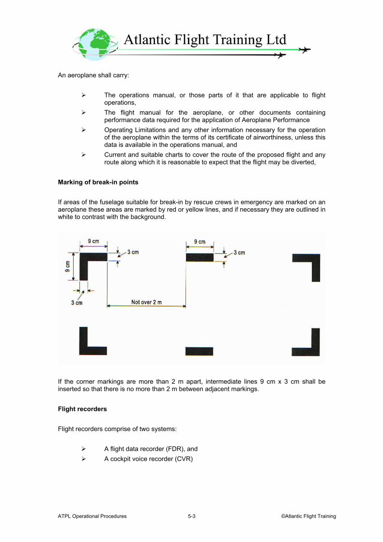
ATPL Operational Procedures ©Atlantic Flight Training 5-3
An aeroplane shall carry:
The operations manual, or those parts of it that are applicable to flight operations,
The flight manual for the aeroplane, or other documents containing performance data required for the application of Aeroplane Performance
Operating Limitations and any other information necessary for the operation of the aeroplane within the terms of its certificate of airworthiness, unless this data is available in the operations manual, and
Current and suitable charts to cover the route of the proposed flight and any route along which it is reasonable to expect that the flight may be diverted,
Marking of break-in points If areas of the fuselage suitable for break-in by rescue crews in emergency are marked on an aeroplane these areas are marked by red or yellow lines, and if necessary they are outlined in white to contrast with the background.
If the corner markings are more than 2 m apart, intermediate lines 9 cm x 3 cm shall be inserted so that there is no more than 2 m between adjacent markings. Flight recorders Flight recorders comprise of two systems:
A flight data recorder (FDR), and A cockpit voice recorder (CVR)
ATPL Operational Procedures 28 October 2003 5-4
Combination recorders (FDR/CVR) can only be used to meet the flight recorder equipage requirements as specifically indicated in this Annex. Flight data recorders – types A Type I flight data recorder records the following:
Flight path Speed Attitude Engine power Configuration, and Operation
Types II and IIA flight data recorders record the following:
Flight path Speed Attitude Engine power, and Configuration of lift and drag devices.
All aeroplanes equipped to utilize digital communications and required to carry a cockpit voice recorder shall record on the cockpit voice recorder or the flight data recorder the digital communications with ATS. Flight data recorders – duration All flight data recorders have to be capable of retaining the information recorded during at least the last 25 hours of their operation, except for the Type II A flight data recorder which has to be capable of retaining the information recorded during at least the last 30 minutes of its operation.
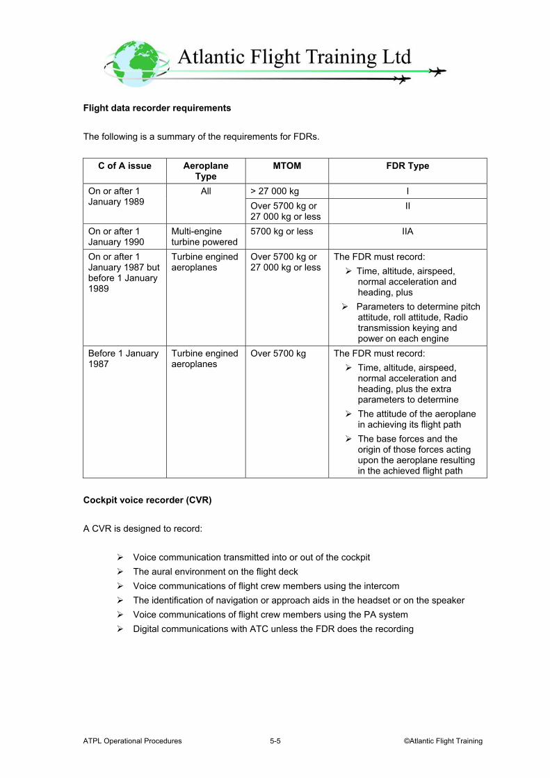
ATPL Operational Procedures ©Atlantic Flight Training 5-5
Flight data recorder requirements The following is a summary of the requirements for FDRs.
C of A issue Aeroplane Type
MTOM FDR Type
> 27 000 kg I On or after 1 January 1989
All Over 5700 kg or 27 000 kg or less
II
On or after 1 January 1990
Multi-engine turbine powered
5700 kg or less IIA
On or after 1 January 1987 but before 1 January 1989
Turbine engined aeroplanes
Over 5700 kg or 27 000 kg or less
The FDR must record: Time, altitude, airspeed,
normal acceleration and heading, plus
Parameters to determine pitch attitude, roll attitude, Radio transmission keying and power on each engine
Before 1 January 1987
Turbine engined aeroplanes
Over 5700 kg The FDR must record: Time, altitude, airspeed,
normal acceleration and heading, plus the extra parameters to determine
The attitude of the aeroplane in achieving its flight path
The base forces and the origin of those forces acting upon the aeroplane resulting in the achieved flight path
Cockpit voice recorder (CVR) A CVR is designed to record:
Voice communication transmitted into or out of the cockpit The aural environment on the flight deck Voice communications of flight crew members using the intercom The identification of navigation or approach aids in the headset or on the speaker Voice communications of flight crew members using the PA system Digital communications with ATC unless the FDR does the recording
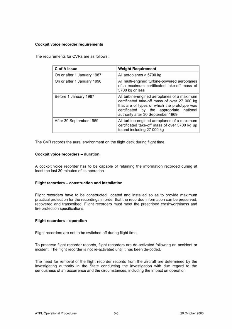
ATPL Operational Procedures 28 October 2003 5-6
Cockpit voice recorder requirements The requirements for CVRs are as follows:
C of A Issue Weight Requirement On or after 1 January 1987 All aeroplanes > 5700 kg On or after 1 January 1990 All multi-engined turbine-powered aeroplanes
of a maximum certificated take-off mass of 5700 kg or less
Before 1 January 1987 All turbine-engined aeroplanes of a maximum certificated take-off mass of over 27 000 kg that are of types of which the prototype was certificated by the appropriate national authority after 30 September 1969
After 30 September 1969 All turbine-engined aeroplanes of a maximum certificated take-off mass of over 5700 kg up to and including 27 000 kg
The CVR records the aural environment on the flight deck during flight time. Cockpit voice recorders – duration A cockpit voice recorder has to be capable of retaining the information recorded during at least the last 30 minutes of its operation. Flight recorders – construction and installation Flight recorders have to be constructed, located and installed so as to provide maximum practical protection for the recordings in order that the recorded information can be preserved, recovered and transcribed. Flight recorders must meet the prescribed crashworthiness and fire protection specifications. Flight recorders – operation Flight recorders are not to be switched off during flight time. To preserve flight recorder records, flight recorders are de-activated following an accident or incident. The flight recorder is not re-activated until it has been de-coded. The need for removal of the flight recorder records from the aircraft are determined by the investigating authority in the State conducting the investigation with due regard to the seriousness of an occurrence and the circumstances, including the impact on operation
ATPL Operational Procedures ©Atlantic Flight Training 5-7
Flight recorders – continued serviceability Operational checks and evaluations of recordings from the flight data and cockpit voice recorder systems are conducted to ensure the continued serviceability of the recorders. FDR and CVR – General requirements
FDR CVR Container Colour – Orange or yellow
It must: Carry reflective material to help in its location Have an underwater location system
Colour – Orange or yellow It must:
Carry reflective material to help in its location Have an underwater location system
Installation The system must be installed so that:
The probability of damage is minimized (Normally as far aft as possible in the vicinity of the rear bulkhead) Electrical power is received from a bus that provides maximum reliability for recording There is a method for pre-flight checking of serviceability
To aid in voice recording, microphones are located in the best positions for the communications of both pilots. The system must be installed so that:
The probability of damage is minimized (Normally as far aft as possible in the vicinity of the rear bulkhead) Electrical power is received from a bus that provides maximum reliability for recording There is a method for pre-flight checking of serviceability If there is an erasure device the system should not self erase on impact or crash
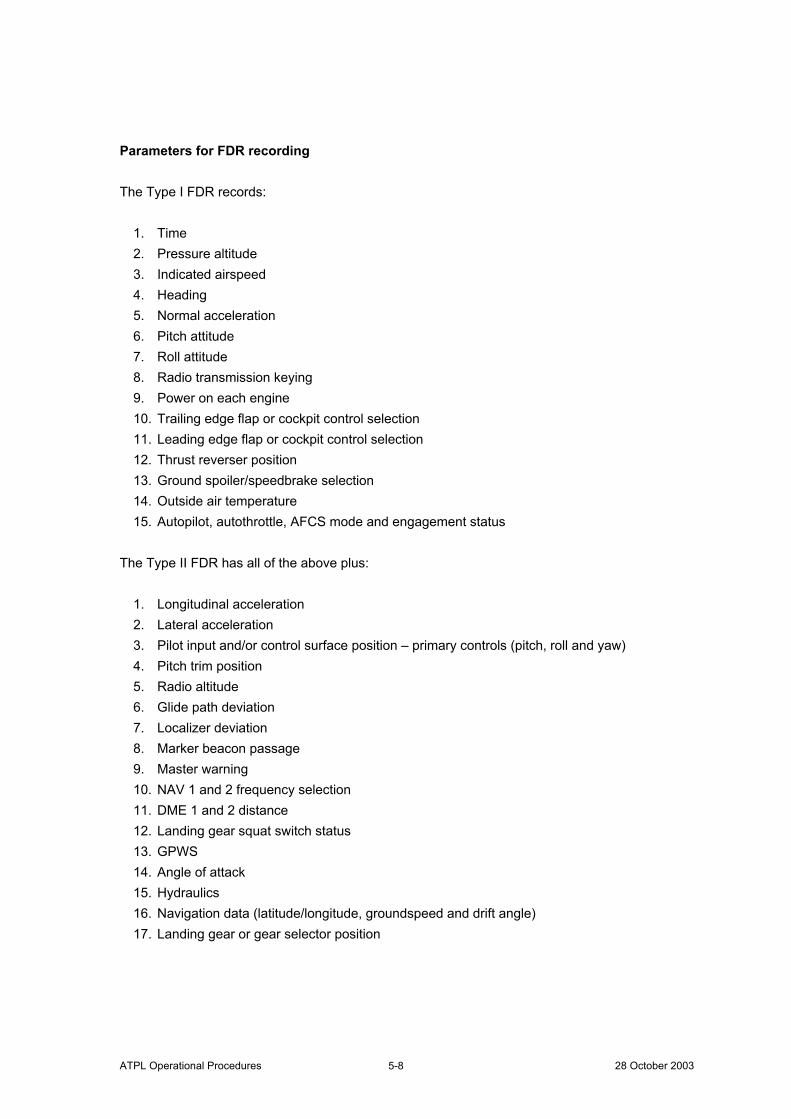
ATPL Operational Procedures 28 October 2003 5-8
Parameters for FDR recording The Type I FDR records:
1. Time 2. Pressure altitude 3. Indicated airspeed 4. Heading 5. Normal acceleration 6. Pitch attitude 7. Roll attitude 8. Radio transmission keying 9. Power on each engine 10. Trailing edge flap or cockpit control selection 11. Leading edge flap or cockpit control selection 12. Thrust reverser position 13. Ground spoiler/speedbrake selection 14. Outside air temperature 15. Autopilot, autothrottle, AFCS mode and engagement status
The Type II FDR has all of the above plus:
1. Longitudinal acceleration 2. Lateral acceleration 3. Pilot input and/or control surface position – primary controls (pitch, roll and yaw) 4. Pitch trim position 5. Radio altitude 6. Glide path deviation 7. Localizer deviation 8. Marker beacon passage 9. Master warning 10. NAV 1 and 2 frequency selection 11. DME 1 and 2 distance 12. Landing gear squat switch status 13. GPWS 14. Angle of attack 15. Hydraulics 16. Navigation data (latitude/longitude, groundspeed and drift angle) 17. Landing gear or gear selector position
ATPL Operational Procedures ©Atlantic Flight Training 5-9
All aeroplanes operated as VFR flights All aeroplanes when operated as VFR flights shall be equipped with:
A magnetic compass An accurate timepiece indicating the time in hours, minutes and seconds A sensitive pressure altimeter An airspeed indicator, and Such additional instruments or equipment as may be prescribed by the
appropriate authority. VFR flights that are operated as controlled flights have to be equipped in accordance with IFR. All aeroplanes on flights over water Seaplanes All seaplanes are equipped with:
One life jacket, or equivalent individual floatation device, for each person on board, stowed in a position easily accessible from the seat or berth of the person for whose use it is provided
Equipment for making the sound signals prescribed in the International Regulations for Preventing Collisions at Sea, where applicable; and
One sea anchor (drogue) Landplanes Landplanes carry the equipment listed below when:
Flying over water and at a distance of more than 93 km (50 nm) away from the shore, in the case of landplanes operated in accordance with the En-route – one power unit inoperative and En-route – two power units inoperative requirements
Flying en route over water beyond gliding distance from the shore, in the case of all other landplanes, and
Taking off or landing at an aerodrome where, in the opinion of the State of the Operator, the take-off or approach path is so disposed over water that in the event of a mishap there would be a likelihood of a ditching.
The equipment required is one life jacket or equivalent individual floatation device for each person on board, stowed in a position easily accessible from the seat or berth of the person for whose use it is provided.
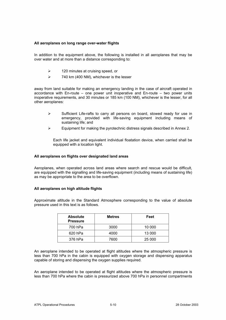
ATPL Operational Procedures 28 October 2003 5-10
All aeroplanes on long range over-water flights In addition to the equipment above, the following is installed in all aeroplanes that may be over water and at more than a distance corresponding to:
120 minutes at cruising speed, or 740 km (400 NM), whichever is the lesser
away from land suitable for making an emergency landing in the case of aircraft operated in accordance with En-route – one power unit inoperative and En-route – two power units inoperative requirements, and 30 minutes or 185 km (100 NM), whichever is the lesser, for all other aeroplanes:
Sufficient Life-rafts to carry all persons on board, stowed ready for use in emergency, provided with life-saving equipment including means of sustaining life; and
Equipment for making the pyrotechnic distress signals described in Annex 2.
Each life jacket and equivalent individual floatation device, when carried shall be equipped with a location light.
All aeroplanes on flights over designated land areas Aeroplanes, when operated across land areas where search and rescue would be difficult, are equipped with the signalling and life-saving equipment (including means of sustaining life) as may be appropriate to the area to be overflown. All aeroplanes on high altitude flights Approximate altitude in the Standard Atmosphere corresponding to the value of absolute pressure used in this text is as follows.
Absolute Pressure
Metres Feet
700 hPa 3000 10 000 620 hPa 4000 13 000 376 hPa 7600 25 000
An aeroplane intended to be operated at flight altitudes where the atmospheric pressure is less than 700 hPa in the cabin is equipped with oxygen storage and dispensing apparatus capable of storing and dispensing the oxygen supplies required. An aeroplane intended to be operated at flight altitudes where the atmospheric pressure is less than 700 hPa where the cabin is pressurized above 700 hPa in personnel compartments
ATPL Operational Procedures ©Atlantic Flight Training 5-11
is provided with oxygen storage and dispensing apparatus capable of storing and dispensing the oxygen supplies required. Pressurized aeroplanes introduced into service on or after 1 July 1962 and intended to be operated at flight altitudes where the atmospheric pressure is less than 376 hPa are equipped with a device to provide positive warning to the pilot of any dangerous loss of pressurization. An aeroplane intended to be operated at flight altitudes at which the atmospheric pressure is less than 376 hPa, or which, if operated at flight altitudes at which the atmospheric pressure is more than 376 hPa, cannot descend safely within four minutes to a flight altitude at which the atmospheric pressure is equal to 620 hPa and for which the individual certificate of airworthiness is first issued on or after 9 November 1998 is provided with automatically deployable oxygen equipment to satisfy the requirements. The total number of oxygen dispensing units has to exceed the number of passenger and cabin attendant seats by at least 10 per cent. All aeroplanes in icing conditions All aeroplanes have to be equipped with suitable anti-icing and/or de-icing devices if it is to be operated where icing conditions are reported to exist or are expected to be encountered. All aeroplanes operated in accordance with instrument flight rules All aeroplanes operated in accordance with instrument flight rules, or when the aeroplane cannot be maintained in a desired attitude without reference to one or more flight instruments, have to be equipped with:
A magnetic compass An accurate timepiece indicating the time in hours, minutes and seconds Two sensitive pressure altimeters with counter drum-pointer or equivalent
presentation. Neither three-pointer nor drum-pointer altimeters satisfy the requirement.
An airspeed indicating system with means of preventing malfunctioning due to either condensation or icing
A turn and slip indicator An attitude indicator (artificial horizon) A heading indicator (directional gyroscope)
The requirements of the turn and slip, attitude indicator and heading
indicator may be met by combinations of instruments or by integrated flight director systems provided that the safeguards against total failure, inherent in the three separate instruments, are retained,
ATPL Operational Procedures 28 October 2003 5-12
A means of indicating whether the power supply to the gyroscopic instrument is adequate
A means of indicating in the flight crew compartment the outside air temperature
A rate-of-climb and descent indicator, and Such additional instruments or equipment as may be prescribed by the
appropriate authority. All aeroplanes over 5700 kg – Emergency power supply for electrically operated attitude indicating instruments All aeroplanes of a maximum certificated take-off mass of over 5700 kg newly introduced into service after 1 January 1975 are fitted with an emergency power supply, independent of the main electrical generating system, for the purpose of operating and illuminating, for a minimum period of 30 minutes, an attitude indicating instrument (artificial horizon), clearly visible to the pilot-in-command. The emergency power supply automatically operates after the total failure of the main electrical generating system and a clear indication is given on the instrument panel that the attitude indicator(s) is being operated by emergency power. Those instruments that are used by any one pilot have to be arranged to permit the pilot to see their indications readily, with the minimum practicable deviation from the position and line of vision normally assumed when looking forward along the flight path. All aeroplanes when operated at night All aeroplanes, when operated at night have to be equipped with:
All equipment specified for IFR The lights required by Annex 2 for aircraft in flight or operating on the
movement area of an aerodrome Two landing lights Illumination for all instruments and equipment that are essential for the safe
operation of the aeroplane that are used by the flight crew Lights in all passenger compartments, and An electric torch for each crewmember station.
Pressurized aeroplanes when carrying passengers – weather radar Pressurized aeroplanes when carrying passengers should be equipped with operative weather radar whenever they are being operated in areas where thunderstorms or other potentially hazardous weather conditions, detectable with airborne weather radar, may be expected to exist.
ATPL Operational Procedures ©Atlantic Flight Training 5-13
All aeroplanes operated above 15 000 m (49 000 ft) – radiation indicator All aeroplanes intended to be operated above 15 000 m (49 000 ft) carry equipment to measure and indicate continuously the dose rate of total cosmic radiation being received and the cumulative dose on each flight. The display unit of the equipment shall be readily visible to a flight crewmember. Individual records are kept for crewmembers who are liable to high exposure. The PIC or the pilot to whom the flight has been delegated will initiate a descent as soon as practicable when the limit values of cosmic radiation specified have been exceeded. All aeroplanes complying with the noise certification Standards in Annex 16, Volume I An aeroplane has to carry a document attesting noise certification. The attestation may be contained in any document, carried on board, approved by the State of Registry. Mach number indicator All aeroplanes with speed limitations expressed in terms of Mach number are equipped with a Mach number indicator. This does not stop the use of the airspeed indicator to derive Mach number for ATS purposes. Aeroplanes required to be equipped with ground proximity warning systems (GPWS) A ground proximity warning system is fitted to:
All turbine-engined aeroplanes of a maximum certificated take-off mass in excess of 15 000kg or authorized to carry more than 30 passengers, for which the individual certificate of airworthiness is first issued on or after 1 July 1979
All turbine-engined aeroplanes of a maximum certificated take-off mass in excess of 5700 kg or authorized to carry more than nine passengers shall be equipped with a ground proximity warning system from 1 January 1999.
A ground proximity warning system provides automatic and timely warning to the flight crew when the aeroplane is in potentially hazardous proximity to the earth’s surface.
ATPL Operational Procedures 28 October 2003 5-14
From 1 January 1999, a ground proximity warning system shall provide, as a minimum, warnings of the following circumstances:
Excessive descent rate Excessive terrain closure rate Excessive altitude loss after take-off or go-around Unsafe terrain clearance while not in landing configuration
Gear not locked down Flaps not in a landing position, and
Excessive descent below the instrument glide path. All piston-engined aeroplanes of a maximum certificated take-off mass in excess of 5700 kg or authorized to carry more than nine passengers should be equipped with a ground proximity warning system. Aeroplanes carrying passengers – cabin attendants’ seats Aeroplanes for which the individual certificate of airworthiness is first issued on or after 1 January 1981 All aeroplanes are equipped with a forward or rearward facing (within 15° of the longitudinal axis of the aeroplane) seat, fitted with a safety harness for the use of each cabin attendant required to satisfy the standard regarding emergency evacuation. Aeroplanes for which the individual certificate of airworthiness was first issued before 1 January 1981 All aeroplanes should be equipped with a forward or rearward facing (within 15° of the longitudinal axis of the aeroplane) seat, fitted with a safety harness for the use of each cabin attendant required to satisfy the standard regarding emergency evacuation. Cabin attendants’ seats provided in accordance with the above are located near floor level and other emergency exits as required by the State of Registry for emergency evacuation. Emergency locator transmitter (ELT) All aeroplanes operated on long range over water flights are equipped with at least two ELT(S). Aeroplanes on flights over designated land areas shall be equipped with at least one ELT(S).
ATPL Operational Procedures ©Atlantic Flight Training 5-15
Aeroplanes required to be equipped with an airborne collision avoidance system (ACAS II) An airborne collision avoidance system (ACAS II) is to be fitted:
From 1 January 2003, to all turbine-engined aeroplanes of a maximum certificated take-off mass in excess of 15 000 kg or authorized to carry more than 30 passengers
From 1 January 2005, all turbine-engined aeroplanes of a maximum certificated take-off mass in excess of 5 700 kg or authorized to carry more than 19 passengers shall be equipped with an airborne collision avoidance system (ACAS II).
Aeroplanes required to be equipped with a pressure-altitude reporting transponder All aeroplanes are to be equipped with a pressure-altitude reporting transponder which operates in accordance with the relevant provisions of Annex 10, Volume IV. This provision is intended to improve the effectiveness of air traffic services as well as airborne collision avoidance systems. Microphones All flight crewmembers required to be on flight deck duty communicate through boom or throat microphones below the transition level/altitude. Turbo-jet aeroplanes - forward-looking wind shear warning system All turbo-jet aeroplanes of a maximum certificated take-off mass in excess of 5700 kg or authorized to carry more than nine passengers should be equipped with a forward-looking wind shear warning system. A forward-looking wind shear warning system should be capable of providing the pilot with a timely aural and visual warning of wind shear ahead of the aircraft, and the information required to permit the pilot to safely commence and continue a missed approach or go-around or to execute an escape manoeuvre if necessary. The system should also provide an indication to the pilot when the limits specified for the certification of automatic landing equipment are being approached, when such equipment is in use. Master Minimum Equipment List (MMEL) The MMEL is formulated by the designer and approved by the State of Design. The information provided allows operators to produce the MEL. The MMEL should not be used as the MEL.
ATPL Operational Procedures 28 October 2003 5-16
Minimum Equipment List (MEL) If deviations from the requirements of States in the certification of aircraft were not permitted an aircraft could not be flown unless all systems and equipment were operable. Experience has proved that some unserviceability can be accepted in the short term when the remaining operative systems and equipment provide for continued safe operations. The State should indicate through approval of a minimum equipment list those systems and items of equipment that may be inoperative for certain flight conditions with the intent that no flight can be conducted with inoperative systems and equipment other than those specified. A minimum equipment list, approved by the State of the Operator, is therefore necessary for each aircraft, based on the master minimum equipment list established for the aircraft type by the organization responsible for the type design in conjunction with the State of Design. The State of the Operator should require the operator to prepare a minimum equipment list designed to allow the operation of an aircraft with certain systems or equipment inoperative provided an acceptable level of safety is maintained. The minimum equipment list is not intended to provide for operation of the aircraft for an indefinite period with inoperative systems or equipment. The basic purpose of the minimum equipment list is to permit the safe operation of an aircraft with inoperative systems or equipment within the framework of a controlled and sound programme of repairs and parts replacement. Operators are to ensure that no flight is commenced with multiple minimum equipment list items inoperative without determining that any interrelationship between inoperative systems or components will not result in an unacceptable degradation in the level of safety and/or undue increase in the flight crew workload. The exposure to additional failures during continued operation with inoperative systems or equipment must also be considered in determining that an acceptable level of safety is being maintained. The minimum equipment list may not deviate from requirements of the flight manual limitations section, emergency procedures or other airworthiness requirements of the State of Registry or of the State of the Operator unless the appropriate airworthiness authority or the flight manual provides otherwise. Systems or equipment accepted as inoperative for a flight should be placarded where appropriate and all such items should be noted in the aircraft technical log to inform the flight crew and maintenance personnel of the inoperative system or equipment. For a particular system or item of equipment to be accepted as inoperative, it may be necessary to establish a maintenance procedure, for completion prior to flight, to deactivate or isolate the system or equipment. It may similarly be necessary to prepare an appropriate flight crew operating procedure. The responsibilities of the pilot-in-command in accepting an aeroplane for operation with deficiencies in accordance with a minimum equipment list are specified earlier.
ATPL Operational Procedures ©Atlantic Flight Training 6-1
Chapter 6.
Aeroplane Communication and Navigation Equipment Communication equipment An aeroplane has to be fitted with radio communication equipment capable of:
Conducting two-way communication for aerodrome control purposes Receiving meteorological information at any time during flight, and Conducting two-way communication at any time during flight with at least one
aeronautical station and with such other aeronautical stations and on such frequencies as may be prescribed by the appropriate authority.
The equipment must be able to transmit/receive on the aeronautical emergency frequency 121.5 MHz. Navigation equipment An aeroplane is fitted with navigation equipment which will enable it to proceed:
In accordance with its operational flight plan In accordance with prescribed RNP types, and In accordance with the requirements of air traffic services
except when navigation for flights under visual flight rules are flown by visual reference to landmarks. For flights where, based on Regional Air Navigation Agreement, minimum navigation performance specifications (MNPS) are flown, an aeroplane is fitted with navigation equipment which:
Continuously provides indications of adherence to or departure from track to the required degree of accuracy at any point along that track, and
Has been authorized by the State of the Operator for MNPS operations concerned.
The prescribed minimum navigation performance specifications and the procedures governing their application are published in Regional Supplementary Procedures (Doc 7030).
ATPL Operational Procedures 28 October 2003 6-2
For flights where, based on Regional Air Navigation Agreement, a vertical separation minimum (VSM) of 300 m (1000 ft) is applied above FL 290. an aeroplane:
Is provided with equipment which is capable of: Indicating to the flight crew the flight level being flown Automatically maintaining a selected flight level Providing an alert to the flight crew when a deviation occurs from the
selected flight level. The threshold for the alert shall not exceed ± 90 m (300 if), and
Automatically reporting pressure-altitude
Is authorized by the State of the operator for operation in the airspace concerned.
Redundancy The aeroplane is provided with navigation equipment to ensure that, in the event of the failure of one item of equipment at any stage of the flight, the remaining equipment will enable the aeroplane to navigate in accordance with the above rules. Guidance material relating to aircraft equipment necessary for flight in airspace where a 300m (1000 if) VSM is applied above FL 290 is contained in the Manual on Implementation of a (1000 ft) Vertical Separation Minimum Between FL 290 and FL 410 Inclusive (Doc 9574) On flights where it is intended to land in instrument meteorological conditions an aeroplane is provided with radio equipment capable of receiving signals providing guidance to a point from which a visual landing can be made. This equipment is capable of providing guidance at every aerodrome at which it is intended to land in instrument meteorological conditions and at any designated alternate aerodromes. Installation The equipment installation is such that the failure of any single unit required for either communications or navigation purposes or both does not result in the failure of another unit required for communications or navigation purposes.
ATPL Operational Procedures ©Atlantic Flight Training 7-1
Chapter 7.
Aeroplane Maintenance Definition When the term “aeroplane” is used it includes; powerplants, propellers, components, accessories, instruments, equipment and apparatus including emergency equipment. Operator’s maintenance responsibilities Operators ensure that, in accordance with procedures acceptable to the State of Registry:
Each aeroplane they operate is maintained in an airworthy condition The operational and emergency equipment necessary for an intended flight is
serviceable The Certificate of Airworthiness of each aeroplane they operate remains
valid. An operator cannot operate an aeroplane unless it is maintained and released to service by an approved organization acceptable to the State of Registry. The person signing the maintenance release has to be licensed in accordance with Annex 1. An operator employs personnel to ensure that all maintenance is carried out in accordance with the maintenance control manual. The maintenance of aeroplanes has to be carried out in accordance with the maintenance programme. Operator’s maintenance control manual The operator provides, for maintenance and operational personnel concerned, a maintenance control manual, acceptable to the State of Registry. The operator ensures that the maintenance control manual is amended as necessary to keep the information contained up to date. Copies of all amendments to the operator’s maintenance control manual are given to everyone who has been issued with a manual. The operator provides the State of the Operator and the State of Registry with a copy of the operators maintenance control manual, together with all amendments and/or revisions to it. The manual incorporates any mandatory material required by the State of the Operator or the State of Registry.
ATPL Operational Procedures 28 October 2003 7-2
Maintenance programme The operator provides, for maintenance and operational personnel concerned, a maintenance programme, approved by the State of Registry. The design and application of the operator’s maintenance programme has to observe Human Factors principles. Copies of all amendments to the maintenance programme are given to everyone who has been given a maintenance programme. Maintenance records An operator ensures that the following records are kept for the periods mentioned below
The total time in service (hours, calendar time and cycles, as appropriate) of the aeroplane and all life limited components
The current status of compliance with all mandatory continuing airworthiness information
Appropriate details of modifications and repairs to the aeroplane and its major components
The time in service (hours, calendar time and cycles, as appropriate) since last overhaul of the aeroplane or its components subject to a mandatory overhaul life
The current aeroplane status of compliance with the maintenance programme, and
The above records are kept for at least 90 days after the unit is permanently withdrawn from service
The detailed maintenance records to show that all requirements for signing of a maintenance release have been met.
The record is kept for a minimum of one year after the maintenance release is signed Where there is a temporary change of operator, the records are made available to the new operator. In the event of any permanent change of operator, the records are transferred to the new operator. Continuing airworthiness information The operator of an aeroplane over 5700 kg maximum certificated take-off mass monitors and assesses maintenance and operational experience with respect to continuing airworthiness and provide the information as prescribed by the State of Registry and reports through the system specified in Annex 8, Part II, 4.2.5 and 4.2.8. The operator of an aeroplane over 5700 kg maximum certificated take-off mass obtains and assesses continuing airworthiness information and recommendations available from the
ATPL Operational Procedures ©Atlantic Flight Training 7-3
organization responsible for the type design and shall implement resulting actions considered necessary in accordance with a procedure acceptable to the State of Registry. Modifications and repairs All modifications and repairs must comply with airworthiness requirements acceptable to the State of Registry. Procedures are established to ensure that the data supporting compliance with the airworthiness requirements are retained. Approved maintenance organization Issue of approval The issue of a maintenance organization approval by a State is dependent upon the applicant demonstrating compliance with the requirements for such an organization. The approval document contains:
Organization’s name and location; Date of issue and period of validity; Terms of approval.
The validity of the approval depends on the organization remaining in compliance with the requirements for an approved maintenance organization. Maintenance organization’s procedures manual The maintenance organization provides a procedures manual for maintenance personnel. This manual must be kept up to date. Copies of all amendments to the procedures manual are given to the relevant personnel. Maintenance procedures and quality assurance system The maintenance organization establishes procedures that ensure good maintenance practices and compliance with all the relevant requirements. This is done by:
Establishing an independent quality assurance system, or By providing a system of inspection to ensure that all maintenance is properly
performed.
ATPL Operational Procedures 28 October 2003 7-4
Facilities The facilities and working environment have to be appropriate for the task to be performed. The maintenance organization must have the necessary technical data, equipment, tools and material to perform the work for which it is approved. Storage facilities have to be provided for parts, equipment, tools and material. Storage conditions must provide security and prevent deterioration of and damage to stored items. Personnel The maintenance organization nominates personnel whose responsibilities include ensuring that the maintenance organization is in compliance with the requirements for issue of approval for an approved maintenance organization. The maintenance organization also employs the necessary personnel to plan, perform, supervise, inspect and release the work to be performed. The competence of maintenance personnel is established in accordance with a procedure and to a level acceptable to the State granting the approval. The person signing a maintenance release has to be qualified in accordance with Annex 1. The maintenance organization ensures that all maintenance personnel receive initial and continuation training appropriate to their assigned tasks and responsibilities. The training programme established by the maintenance organization must include training in knowledge and skills related to human performance, including co-ordination with other maintenance personnel and flight crew. Records The maintenance organization retains detailed maintenance records to show that all requirements for the signing of a maintenance release have been met. These records are kept for as minimum of one year after the maintenance release has been signed. Maintenance release A maintenance release is completed and signed to certify that the maintenance work performed has been completed satisfactorily and in accordance with the procedures described in the maintenance organization’s procedures manual. A maintenance release shall contain a certification including:
Basic details of the maintenance carried out Date such maintenance was completed When applicable, the identity of the approved maintenance organization, and The identity of the person or persons signing the release.
ATPL Operational Procedures ©Atlantic Flight Training 8-1
Chapter 8.
Aeroplane Flight Crew Composition of the flight crew The number and composition of the flight crew cannot be less than that specified in the operations manual. This number is based on the number specified in the C of A. Radio operator The flight crew must include one member who holds a valid radio licence, issued or validated by the State of Registry. Flight engineer When a flight engineer’s station is incorporated in the design of an aeroplane, the flight crew must include at least one flight engineer assigned to that station. If the duties associated with that station can be satisfactorily performed by another flight crew member, holding a flight engineer licence, then a flight engineer need not be carried. Flight navigator The flight crew must include at least one member who holds a flight navigator licence where the safe conduct of the flight cannot be adequately accomplished by the pilots from the pilot station, Flight crew member emergency duties An operator assigns to all flight crew members the necessary duties they are to perform in an emergency or in a situation requiring emergency evacuation. Annual training required is contained in the operator’s training programme and includes:
Instruction in the use of all emergency and lifesaving equipment required to be carried, and
Drills in the emergency evacuation of the aeroplane.
ATPL Operational Procedures 28 October 2003 8-2
Flight crew member training programmes An operator establishes and maintains a ground and flight training programme, approved by the State of the Operator, that ensures that flight crew members are adequately trained to perform their assigned duties. Ground and flight training have to be provided. The training consists of ground and flight training in the type(s) of aeroplane on which the flight crew member serves, and shall include:
Proper flight crew coordination and training in all types of emergency. Training in human performance, and Training in the transport of dangerous goods.
The training for each flight crew member ensures that all flight crew members know the functions for which they are trained. The training programme is given on a recurrent basis, as determined by the State of the Operator and includes an examination to determine competence. The requirement for recurrent flight training in a particular type of aeroplane is:
The use of aeroplane synthetic flight trainers approved by that State for that purpose, or
The completion within the appropriate period of the proficiency check required in that type of aeroplane.
Qualifications Recent experience - pilot-in-command A pilot cannot be used as pilot-in-command of an aeroplane unless, on the same type of aeroplane within the preceding 90 days, that pilot has made at least three take-off and landings. Recent experience - co-pilot A co-pilot cannot operate at the flight controls during take-off and landing unless:
On the same type of aeroplane within the preceding 90 days, that co-pilot has operated the flight controls, as pilot-in-command or as co-pilot, during three take-off and landings, or
Has otherwise demonstrated competence to act as co-pilot on a flight simulator approved for the purpose.
ATPL Operational Procedures ©Atlantic Flight Training 8-3
Pilot-in-command - route and airport qualification An operator cannot use a pilot as pilot-in-command of an aeroplane on a route unless he complies with the Standards below. The pilot must demonstrate to the operator an adequate knowledge of:
The route to be flown, and the aerodromes which are to be used. This shall include knowledge of:
The terrain and minimum safe altitudes The seasonal meteorological conditions The meteorological, communication and air traffic facilities, services
and procedures The search and rescue procedures The navigational facilities and procedures, including any long-range
navigation procedures, associated with the route along which the flight is to take place; and
Procedures applicable to flight paths over heavily populated areas and areas
of high air traffic density, obstructions, physical layout, lighting, approach aids and arrival, departure, holding and instrument approach procedures, and applicable operating minima.
Arrival, departure, holding and instrument approach procedures may be flown in an appropriate training device which is adequate for this purpose. A pilot-in-command must have made an actual approach into each aerodrome of landing on the route, accompanied by a pilot who is qualified for the aerodrome, as a member of the flight crew or as an observer on the flight deck, unless:
The approach to the aerodrome is not over difficult terrain and the instrument approach procedures and aids available are similar to those with which the pilot is familiar, and a margin to be approved by the State of the Operator is added to the normal operating minima, or there is reasonable certainty that approach and landing can be made in visual meteorological conditions, or
The descent from the initial approach altitude can be made by day in visual meteorological conditions, or
The operator qualifies the pilot-in-command to land at the aerodrome concerned by means of an adequate pictorial presentation, or
The aerodrome concerned is adjacent to another aerodrome at which the pilot-in-command is currently qualified to land.
The operator maintains a record of the qualification of the pilot and of the way the qualification was granted.
ATPL Operational Procedures 28 October 2003 8-4
An operator shall not continue to use a pilot as a pilot-in-command on a route unless, within the preceding 12 months, he has made at least one trip between the terminal points of that route as:
A pilot member of the flight crew, or As a check pilot, or As an observer on the flight deck.
In the event that more than 12 months elapse the pilot must requalify in accordance with the above rules. Nomination as Commander To upgrade to commander from co-pilot the command course must consist of the training specified in the Operations Manual:
Training in a simulator and/or flying training An operator proficiency check operating as commander Commander’s responsibilities Line training in command under supervision. A minimum of 10 sectors for pilots
already qualified on type. Completion of a commander’s line check Elements of CRM
Pilot proficiency checks An operator ensures that a pilot’s competence is checked at regular intervals. This includes compliance with IFR which must be demonstrated to a check pilot or an authority examiner. These checks are carried out twice within any period of one year. Any two checks which are similar and which occur within a period of four consecutive months do not satisfy this requirement. Flight crew equipment A flight crew member who uses correcting lenses must have a spare set of the correcting lenses readily available when flying. Flight time, flight duty periods and rest periods The State of the Operator establishes regulations specifying the limitations applicable to the flight time and flight duty periods for flight crew members. These regulations make provision for adequate rest periods and ensure that fatigue occurring either in a flight or successive flights or accumulated over a period of time due to these and other tasks, does not endanger the safety of a flight.
ATPL Operational Procedures ©Atlantic Flight Training 9-1
Chapter 9.
Manuals, Logs and Records
Flight manual The flight manual is updated by implementing changes made mandatory by the State of Registry. Journey log book The aeroplane journey log book should contain the following items and the corresponding roman numerals:
I. Aeroplane nationality and registration. II. Date. III. Names of crewmembers. IV. Duty assignments of crewmembers. V. Place of departure. VI. Place of arrival VII. Time of departure. VIII. Time of arrival IX. Hours of flight. X. Nature of flight (private, aerial work scheduled or non-scheduled). XI. Incidents, observations, if any. XII. Signature of person in charge.
Entries in the journey logbook should be made as soon as possible after the flight and in ink or indelible pencil. The completed journey logbook should be retained to provide a continuous record of the last six months’ operations. Operations Manual An operations manual contains the following:
Operations administration and supervision
Instructions outlining the responsibilities of operations personnel pertaining to the conduct of flight operations
Checklist of emergency and safety equipment and instructions for its use.
ATPL Operational Procedures 28 October 2003 9-2
The minimum equipment list for the aeroplane types operated and specific operations authorized, including any requirements relating to operations in RNP airspace.
Safety precautions during refuelling with passengers on board.
Accident prevention and flight safety programme
Details of the accident prevention and flight safety programme including a statement of safety policy and the responsibility of personnel.
Personnel training
Details of the flight crew training programme and requirements. Details of the cabin attendant duties training programme.
Fatigue and flight time limitations
Rules limiting the flight time and flight duty periods and providing for adequate rest periods for flight crewmembers and cabin attendants.
Flight operations
The flight crew for each type of operation including the designation of the succession of command. The in-flight and the emergency duties assigned to each crewmember. Specific instructions for the computation of the quantities of fuel and oil to be carried, having regard to all circumstances of the operation including the possibility of the failure of one or more powerplants while en route. The conditions under which oxygen shall be used and the amount of oxygen carried. Instructions for mass and balance control. Instructions for the conduct and control of ground de/anti-icing operations. The specifications for the operational flight plan.
ATPL Operational Procedures ©Atlantic Flight Training 9-3
The normal, abnormal and emergency procedures to be used by the flight crew, the checklists and aircraft systems information as required. Standard operating procedures (SOP) for each phase of flight. Instructions on the use of normal checklists and the timing of their use. Emergency evacuation procedures.
Departure contingency procedures. Instructions on the maintenance of altitude awareness and the use of automated or flight crew altitude callout. Instructions on the use of autopilots and auto-throttles in IMC. Instructions on the clarification and acceptance of ATC clearances, particularly where terrain clearance is involved. Departure and approach briefings. Route and destination familiarization. Stabilized approach procedure. Limitation on high rates of descent near the surface. Conditions required to commence or to continue an instrument approach. Instructions for the conduct of precision and non-precision instrument approach procedures. Allocation of flight crew duties and procedures for the management of crew workload during night and IMC instrument approach and landing operations. Instructions and training requirements for the avoidance of controlled flight into terrain and policy for the use of the ground proximity warning system (GPWS). Information and instructions relating to the interception of civil aircraft including:
ATPL Operational Procedures 28 October 2003 9-4
Procedures, as prescribed in Annex 2, for pilots-in-command of intercepted aircraft, and
Visual signals for use by intercepting and intercepted aircraft, as contained in Annex 2.
For aeroplanes intended to be operated above 15 000 m (49 000 ft):
Information which will enable the pilot to determine the best course of action to take in the event of exposure to solar cosmic radiation, and
Procedures in the event that a decision to descend is taken, covering
The necessity of giving the appropriate ATS unit prior warning of the situation and of obtaining a provisional descent clearance, and
The action to be taken in the event that communication with the ATS unit cannot be established or is interrupted.
Aeroplane performance
Operating instructions and information on climb performance with all engines operating is provided.
Route guides and charts
A route guide to ensure that the flight crew will have, for each flight, information relating to communication facilities. navigation aids, aerodromes, and such other information as the operator may deem necessary for the proper conduct of flight operations.
Minimum flight altitudes
The method for determining minimum flight altitudes. The minimum flight altitudes for each route to be flown.
Aerodrome operating minima
The methods for determining aerodrome operating minima. Aerodrome operating minima for each of the aerodromes that are likely to be used as aerodromes of intended landing or as alternate aerodromes.
ATPL Operational Procedures ©Atlantic Flight Training 9-5
The increase of aerodrome operating minima in case of degradation of approach or aerodrome facilities.
Search and rescue
The ground-air visual signal code for use by survivors, as contained in Annex 12. Procedures, as prescribed in Annex 12 for pilots-in-command observing an accident.
Dangerous goods
Information and instructions on the carriage of dangerous goods, including action to be taken in the event of an emergency.
Navigation
A list of the navigational equipment to be carried including any requirements relating to operations in RNP airspace. Where relevant to the operations the long-range navigation procedures to be used.
Communications
The circumstances in which a radio listening watch is to be maintained. Security
Security instructions and guidance. The search procedure checklist. Human Factors
Information on the operators’ training programme for the development of knowledge and skills related to human performance.
Records of emergency and survival equipment carried Where required the operator will give the following information to a Rescue Coordination Centre:
The number, colour and type of life rafts and pyrotechnics
ATPL Operational Procedures 28 October 2003 9-6
Details of emergency medical supplies, and water supplies and the type, and Frequencies of the emergency portable radio equipment.
ATPL Operational Procedures ©Atlantic Flight Training 10-1
Chapter 10.
Security Security of the flight crew compartment Where a flight compartment door is fitted to an aircraft it must be capable of being locked from the inside only.
Aeroplane search procedure checklist An operator ensures that there is an on board checklist of the procedures for searching for a bomb in case of suspected sabotage. The checklist is supported by guidance on the course of action to be taken if a bomb or suspicious object is found. Information is also given on the least-risk bomb location specific to the aeroplane. Training programmes An operator establishes a training programme that enables crew members to act in the most appropriate manner to minimize the consequences of acts of unlawful interference. Reporting acts of unlawful interference Following an act of unlawful interference the pilot-in-command shall submit, without delay, a report of such an act to the designated local authority.

ATPL Operational Procedures 28 October 2003 10-2
Intentionally Left Blank
ATPL Operational Procedures ©Atlantic Flight Training 11-1
PART 2. JAR-OPS 1
Chapter 11.
General Requirements Introduction The following chapters refer to JAR-OPS 1. This document is written for Commercial Air Transportation (Aeroplanes) and is split into two sections:
Section 1 Requirements Section 2 Advisory Circulars Joint (ACJ)/ Acceptable Means of Compliance
(AMC)/ Interpretative and Explanatory Material (IEM)
JAR-OPS 1.035 - Quality System a. Operators are required to establish a Quality System and designate a Quality
Manager to monitor the procedures required thus ensuring safe operational practices and airworthy aeroplanes.
b. The Quality System must include a Quality Assurance Programme that contains
procedures designed to verify that operations are being conducted in accordance with all applicable requirements, standards and procedures.
c. The Quality System and the Quality Manager must be acceptable to the Authority. d. The Quality System must have a valid Quality Manual. JAR-OPS 1.037 - Accident Prevention and Flight Safety Programme a. An operator must establish an accident prevention and flight safety programme which
may be integrated with the Quality System. JAR-OPS 1.040 - Additional Crew Members The operator ensures that crew members, who are not flight or cabin crew members, have been trained for their assigned duties. JAR-OPS 1.075 - Method of Carriage of Persons a. An operator must take all reasonable means to ensure that no person is carried in
any part of an aeroplane other than the passenger compartment unless temporary access has been granted by the commander to any part of the aeroplane:
i. For the safety of the aeroplane or of any person, animal or goods; or ii. Where cargo or stores are carried as long as the compartment is designed to enable a person to have access while the aeroplane is in flight.
ATPL Operational Procedures 28 October 2003 11-2
JAR-OPS 1.085 - Crew Responsibilities a. A crew member is responsible for the proper execution of his duties that:
i. Are related to the safety of the aeroplane and its occupants; and ii. Are specified in the instructions and procedures laid down in the Operations Manual.
b. A crew member:
i. Reports to the commander any incident that has endangered, or may have endangered, safety; and ii. Makes use of the operator's incident reporting schemes. In all cases, a copy of the report(s) is communicated to the commander.
c. A crew member must not perform duties on an aeroplane:
i. While under the influence of any drug that may affect his faculties in a manner contrary to safety; ii. Until a reasonable time period has elapsed after deep water diving; iii. Following blood donation except when a reasonable time period has elapsed; iv. If he is in any doubt of being able to accomplish his assigned duties; or v. If he knows or suspects that he is suffering from fatigue, or feels unfit to the extent that the flight may be endangered.
d. A crew member shall not:
i. Consume alcohol less than 8 hours prior to the specified reporting time for flight duty or the commencement of standby; ii. Commence a flight duty period with a blood alcohol level in excess of 0·2 promille; iii. Consume alcohol during the flight duty period or whilst on standby.
e. The commander shall:
i. Be responsible for the safe operation of the aeroplane and safety of its occupants during flight time; ii. Have authority to give all commands he deems necessary for the purpose of securing the safety of the aeroplane and of persons or property carried therein;
iii. Have authority to disembark any person, or any part of the cargo, which, in his opinion, may represent a potential hazard to the safety of the aeroplane or its occupants;
ATPL Operational Procedures ©Atlantic Flight Training 11-3
iv. Not allow a person to be carried in the aeroplane who appears to be under the influence of alcohol or drugs to the extent that the safety of the aeroplane or its occupants is likely to be endangered; v. Have the right to refuse transportation of inadmissible passengers, deportees
or persons in custody if their carriage poses any risk to the safety of the aeroplane or its occupants;
vi. Ensure that all passengers are briefed on the location of emergency exits and the location and use of relevant safety and emergency equipment; vii. Ensure that all operational procedures and check lists are complied with in accordance with the Operations Manual; viii. Not permit any crew member to perform any activity during take-off, initial climb, final approach and landing except those duties required for the safe operation of the aeroplane; ix. Not permit:
(a) A flight data recorder to be disabled, switched off or erased during flight nor permit recorded data to be erased after flight in the event of an accident or an incident subject to mandatory reporting; (b) A cockpit voice recorder to be disabled or switched off during flight unless he believes that the recorded data, which otherwise would be erased automatically, should be preserved for incident or accident investigation nor permit recorded data to be manually erased during or after flight in the event of an accident or an incident subject to mandatory reporting;
x. Decide whether or not to accept an aeroplane with unserviceabilities allowed
by the CDL or MEL; and
xi. Ensure that the pre-flight inspection has been carried out.
f. The commander or the pilot to whom conduct of the flight has been delegated shall, in an emergency situation that requires immediate decision and action, take any action he considers necessary under the circumstances. In such cases he may deviate from rules, operational procedures and methods in the interest of safety.
JAR-OPS 1.100 - Admission to Flight Deck a. An operator must ensure that no person, other than a flight crew member, is admitted
to, or carried on, the flight deck unless that person is:
i. An operating crew member; ii. A representative of the Authority responsible for certification, licensing or inspection; or iii. Permitted by the instructions contained in the Operations Manual.
ATPL Operational Procedures 28 October 2003 11-4
b. The commander ensures that:
ii. In the interests of safety, admission to the flight deck does not interfere with the flight's operation; and iii. All persons carried on the flight deck are made familiar with the relevant safety procedures.
c. The final decision regarding the admission to the flight deck is the responsibility of the
commander. JAR-OPS 1.110 - Portable Electronic Devices The Operator ensures that Portable Electronic Devices that can affect the performance of aircraft systems are not used. JAR-OPS 1.115 - Alcohol and Drugs The operator ensures that no person enters an aeroplane when under the influence of alcohol or drugs where the safety of the aeroplane or its occupants is likely to be endangered. JAR-OPS 1.120 - Endangering Safety a. An operator must take all reasonable measures to ensure that no person:
i. Recklessly endanger an aeroplane or person; ii. Recklessly permits an aeroplane to endanger any person or property.
JAR-OPS 1.125 - Documents to be Carried a. Operators ensure that the following documents are carried on each flight:
i. Certificate of Registration; ii. Certificate of Airworthiness; iii. Noise Certificate (if applicable); iv. Air Operator Certificate; v. Aircraft Radio Licence; and vi. Third party liability Insurance Certificate(s).
b. Flight crew members carry a valid flight crew licence with appropriate rating(s) on
each flight. Appendix 1 to JAR-OPS 1.125 Where documents are stolen the operation is allowed to continue until the flight reaches a place where replacement documentation can be provided.
ATPL Operational Procedures ©Atlantic Flight Training 11-5
JAR-OPS 1.130 - Manuals to be Carried a. Operators ensure that the following are carried:
i. The relevant sections of the Operations Manual that apply to crew duty; ii. The parts of the Operations Manual which are required for the conduct of a flight; and iii. The current Aeroplane Flight Manual unless the Authority has accepted that the Operations Manual contains relevant information for that aeroplane.
JAR-OPS 1.135 - Additional Information and Forms to be Carried a. Additional information and forms that the Operator must ensure are carried:
i. Operational Flight Plan ii. Aeroplane Technical Log iii. Details of the filed ATS flight plan; iv. Appropriate NOTAM/AIS briefing documentation; v. Appropriate meteorological information; vi. Mass and balance documentation; vii. Notification of special categories of passenger:
i. security personnel if not considered as crew ii. handicapped persons iii. inadmissible passengers iv. deportees and persons in custody;
viii. Notification of special loads including dangerous goods including written information to the commander; ix. Current maps and charts and associated documents x. Any other documentation which may be required by the States concerned with this flight, such as cargo manifest or passenger manifest; and xi. Forms to comply with the reporting requirements of the Authority and the operator.
b. This extra information can be presented on a format other than paper.
ATPL Operational Procedures 28 October 2003 11-6
JAR-OPS 1.140 - Information Retained on the Ground a. An operator ensures that:
i. At least for the duration of each flight;
(a) Information relevant to the flight and appropriate for the type of operation is preserved on the ground; and
(b) The information is retained until it has been duplicated; or, if this is impracticable, (c) The same information is carried in a fireproof container in the aeroplane.
b. The above information includes:
i. A copy of the operational flight plan where appropriate; ii. Copies of the relevant part(s) of the aeroplane technical log; iii. Route specific NOTAM documentation; iv. Mass and balance documentation; and v. Special loads notification.
JAR-OPS 1.145 - Power to Inspect The operator ensures that any person authorised by the Authority is permitted to board and fly in any aeroplane operated in accordance with an AOC issued by that Authority. They may enter and remain on the flight deck provided that the commander can refuse access to the flight deck if, in his opinion, the safety of the aeroplane is compromised. JAR-OPS 1.150 - Production of Documentation and Records a. Operators shall:
i. Give any person authorised by the Authority access to any documents and records which are related to flight operations or maintenance; and ii. Produce all such documents and records, when requested to do so by the Authority, within a reasonable period of time.
b. The commander of an aeroplane must, within a reasonable time of being requested
to do so by the Authority, produce the documentation required to be carried on board.
ATPL Operational Procedures ©Atlantic Flight Training 11-7
JAR-OPS 1.155 - Preservation of Documentation a. An operator ensures that:
i. Any original documentation is preserved for the required retention period after he ceases to be the operator of the aeroplane; and ii. Where a crew member changes employer, he makes available Flight and
Duty Time Limitations and Rest Requirements to the new operator. JAR-OPS 1.160 - Preservation, Production and use of Flight Recorder Recordings a. Preservation of recordings
i. Following an accident, the operator preserves the original recorded data relevant to the accident, for a period of 60 days unless otherwise directed by the investigating authority. ii. Unless permission has been granted by the Authority, following an incident that is subject to mandatory reporting, the operator preserves the recorded data relevant to the incident, for a period of 60 days unless otherwise directed by the authority. iii. When a flight data recorder is required to be carried aboard an aeroplane, the
operator of that aeroplane shall:
(a) Save the recordings for the period of operating time as required except that, for the purpose of testing and maintaining flight data recorders, up to one hour of the oldest recorded material at the time of testing may be erased; and
(b) Keep a document which presents the information necessary to retrieve and convert the stored data into engineering units.
b. Production of recordings. The operator has to produce, within a reasonable time after being requested to do so by the Authority, any recording made by a flight recorder which is available or has been preserved. c. Use of recordings:
i. Cockpit voice recorder recordings may not be used for purposes other than accident investigation except with the consent of all crew members concerned.
ATPL Operational Procedures 28 October 2003 11-8
ii. The flight data recorder recordings may not be used for purposes other than for the investigation of an accident or incident except when the records are:
(a) Used by the operator for airworthiness or maintenance purposes only; or (b) De-identified; or (c) Disclosed under secure procedures.
JAR-OPS 1.165 - Leasing a. Terminology
Terms used in this paragraph have the following meaning:
Dry lease Is when the aeroplane is operated under the AOC of the lessee. Wet lease Is when the aeroplane is operated under the AOC of the lessor.
JAA operator An operator certificated under JAR-OPS Part 1 by one of the JAA Member States.
b. Leasing of aeroplanes between JAA operators
i. Wet lease-out. A JAA operator providing an aeroplane and complete crew to another JAA operator remains the operator of the aeroplane. ii. All leases except wet lease-out
(a) A JAA operator utilising an aeroplane from, or providing it to, another
JAA operator, must obtain prior approval for the operation from his respective Authority. Any conditions which are part of this approval must be included in the lease agreement.
(b) Lease agreements where an aeroplane and complete crew are
involved and no transfer of functions and responsibilities is intended, are to be regarded as variations of the AOC under which the flights will be operated.
c. Leasing of aeroplanes between a JAA operator and any entity other than a JAA
operator
i. Dry lease-in
(a) Dry lease-in from a non-JAA operator is not allowed unless it is approved by the authority.
ATPL Operational Procedures ©Atlantic Flight Training 11-9
ii. Wet lease-in
(a) Wet lease-in of an aeroplane from a non-JAA operator is not allowed without the approval of the Authority.
(b) A JAA operator ensures that, with aeroplanes that are wet leased-in:
i) The safety standards of the lessor with respect to
maintenance and operation are equivalent to JARs;
ii) The lessor is an operator holding an AOC issued by an ICAO Contracting State
iii) The aeroplane has a Certificate of Airworthiness issued in
accordance with ICAO Annex 8. Certificates of Airworthiness issued by a JAA Member State other than the State responsible for issuing the AOC, will be accepted when issued in accordance with JAR-21; and
iv) Any JAA requirement made applicable by the lessee's
Authority is complied with.
iii. Dry lease-out
(a) A JAA operator may dry lease-out an aeroplane to any operator of an ICAO Contracting State provided that the following conditions are met:
i) The Authority has exempted the JAA operator from the relevant provisions of JAR-OPS Part 1 and, the foreign regulatory authority has accepted responsibility in writing for surveillance of the maintenance and operation of the aeroplane(s), has removed the aeroplane from its AOC; and ii) The aeroplane is maintained according to an approved
maintenance programme.
iv Wet lease-out.
(a) A JAA operator providing an aeroplane and complete crew to another operator remains the operator of the aeroplane.
d. Leasing of aeroplanes at short notice. Where a JAA operator needs a replacement aeroplane urgently, the approvals required may be deemed to have been given, provided that:
i The lessor is an operator holding an AOC issued by an ICAO Contracting State
ii. The lease-in period does not exceed 5 consecutive days; and iii. The Authority is immediately notified of the use of this provision.
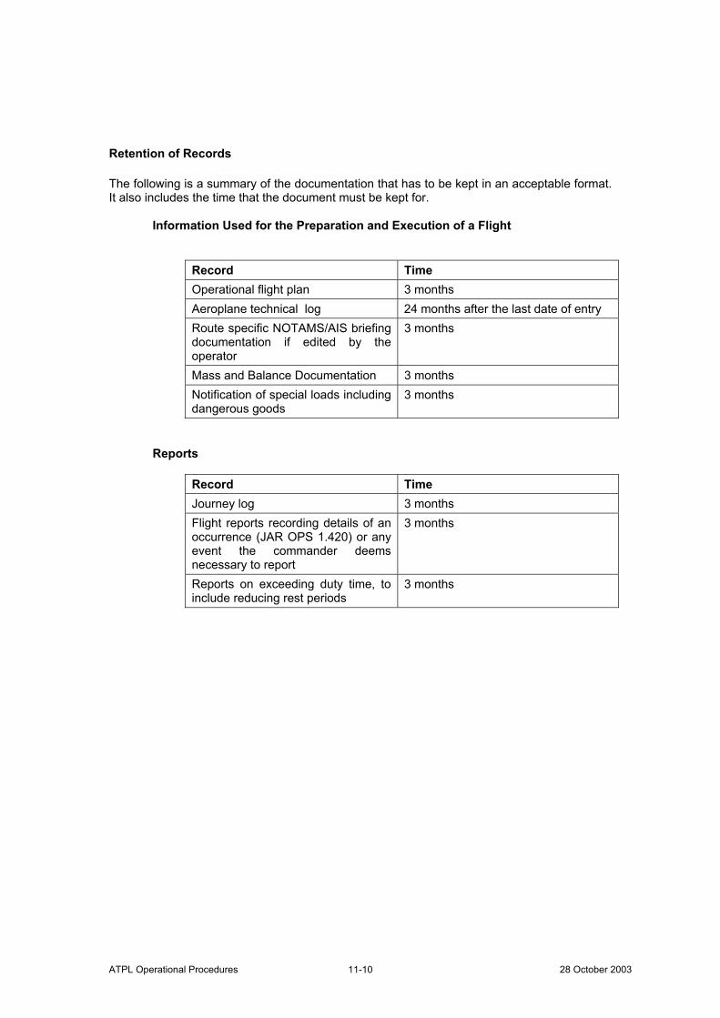
ATPL Operational Procedures 28 October 2003 11-10
Retention of Records The following is a summary of the documentation that has to be kept in an acceptable format. It also includes the time that the document must be kept for.
Information Used for the Preparation and Execution of a Flight
Record Time Operational flight plan 3 months Aeroplane technical log 24 months after the last date of entry Route specific NOTAMS/AIS briefing documentation if edited by the operator
3 months
Mass and Balance Documentation 3 months Notification of special loads including dangerous goods
3 months
Reports
Record Time Journey log 3 months Flight reports recording details of an occurrence (JAR OPS 1.420) or any event the commander deems necessary to report
3 months
Reports on exceeding duty time, to include reducing rest periods
3 months
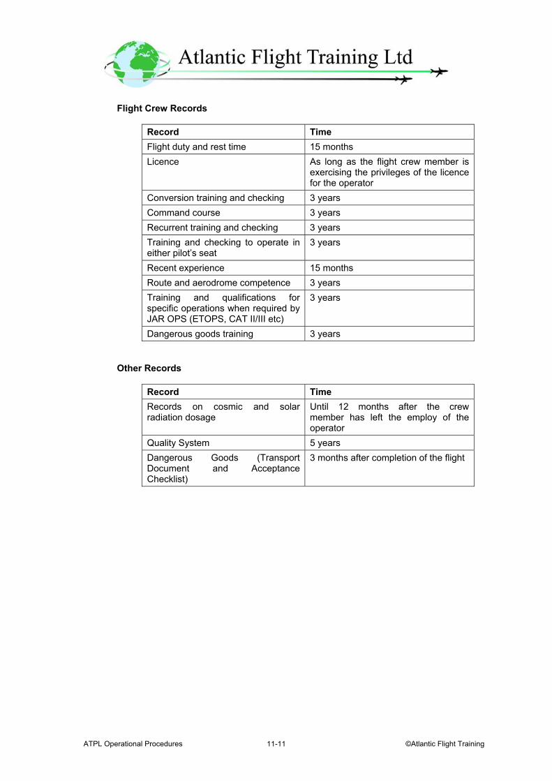
ATPL Operational Procedures ©Atlantic Flight Training 11-11
Flight Crew Records
Record Time Flight duty and rest time 15 months Licence As long as the flight crew member is
exercising the privileges of the licence for the operator
Conversion training and checking 3 years Command course 3 years Recurrent training and checking 3 years Training and checking to operate in either pilot’s seat
3 years
Recent experience 15 months Route and aerodrome competence 3 years Training and qualifications for specific operations when required by JAR OPS (ETOPS, CAT II/III etc)
3 years
Dangerous goods training 3 years
Other Records
Record Time Records on cosmic and solar radiation dosage
Until 12 months after the crew member has left the employ of the operator
Quality System 5 years Dangerous Goods (Transport Document and Acceptance Checklist)
3 months after completion of the flight

ATPL Operational Procedures 28 October 2003 11-12
Intentionally Left Blank
ATPL Operational Procedures ©Atlantic Flight Training 12-1
Chapter 12.
Operator Certification and Supervision Requirements JAR-OPS 1.175 - General Rules for Air Operator Certification a. An operator cannot operate an aeroplane for the purpose of commercial air
transportation except in accordance with the terms and conditions of an Air Operator Certificate (AOC).
b. An applicant for an AOC must allow the Authority to examine all safety aspects of the
proposed operation. c. An applicant for an AOC must:
i. Not hold an AOC issued by another Authority unless specifically approved by the Authorities concerned; ii. Have his principal place of business located in the State responsible for issuing the AOC. iii. Have registered the aeroplanes which are to be operated under the AOC in the State responsible for issuing the AOC; and iv. Satisfy the Authority that he is able to conduct safe operations.
d. With the mutual agreement of the Authority issuing the AOC and another Authority,
aeroplanes registered on the national register of the second-named Authority may be operated.
e. The operator must allow the Authority access to his organisation and to ensure
compliance with JAR-OPS. f. An AOC will be varied, suspended or revoked if the Authority is no longer satisfied
that the operator can maintain safe operations. g. The operator must have:
1. A management organisation capable of exercising operational control and supervision over any flight operated under the terms of its AOC.
2. Nominated an accountable manager, acceptable to the Authority, who has corporate authority for ensuring that all operations and maintenance activities can be financed and carried out to the standard required by the Authority.
ATPL Operational Procedures 28 October 2003 12-2
3. Nominated post holders, acceptable to the Authority, who are responsible for:
i. Flight operations; ii. The maintenance system; iii. Crew training; and iv. Ground operations.
4. A person may hold more than one nominated post when this is acceptable to the authority. Where 21 or more staff are employed then 2 people must be employed to cover the 4 posts.
5. Ensured that every flight is conducted in accordance with the provisions of the Operations Manual.
6. Arranged appropriate ground handling facilities to ensure the safe handling of its flights.
7. Ensure that its aeroplanes are equipped and its crews are qualified, as required for the area and type of operation.
8. Complied with the maintenance requirements, in accordance with Subpart M, for all aeroplanes operated under the terms of its AOC.
9. Provided the Authority with a copy of the Operations Manual and all amendments or revisions to it.
10. Maintained operational support facilities at the main operating base, appropriate for the area and type of operation.
Contents of the AOC The AOC contains the following information:
1. The name and location of the operator 2. The date of issue and the validity period 3. A description of the type of operations authorised 4. The types of aeroplane authorised for use 5. The registrations of all authorised aeroplanes 6. The authorised areas of operation 7. Any special limitations 8. Special authorisations such as:
i. CAT II or CAT III operations with approved minima ii. MNPS iii. ETOPS iv. RNAV v. RVSM vi. Carriage of dangerous goods
ATPL Operational Procedures ©Atlantic Flight Training 12-3
JAR-OPS 1.180 - Issue, Variation and Continued Validity of an AOC a. An operator will not be granted an AOC unless:
i. Aeroplanes operated have a Certificate of Airworthiness issued in accordance with ICAO Annex 8 by a JAA Member State. Certificates of Airworthiness issued by a JAA Member State other than the State responsible for issuing the AOC, will be accepted without further showing when issued in accordance with JAR-21;
ii. The maintenance system has been approved, and iii. The Authority is satisfied that the Operator has the ability to:
(a) Establish and maintain an adequate organisation; (b) Establish and maintain a quality system in accordance with JAR-
OPS; (c) Comply with required training programmes; (d) Comply with maintenance requirements, consistent with the nature and extent of the operations specified
b. The operator must notify the Authority as soon as practicable of any changes to the
information submitted. c. If the Authority is not satisfied that the requirements have been met, they may require
the conduct of one or more demonstration flights, operated as if they were commercial air transport flights.
JAR-OPS 1.195 - Operational Control and Supervision The operator is responsible for operational control and establishing and maintaining a method of supervision of flight operations approved by the Authority. JAR-OPS 1.200 - Operations Manual The operator provides an Operations Manual for the use and guidance of operations personnel. JAR-OPS 1.205 - Competence of Operations Personnel The operator ensures that all personnel are properly instructed, have demonstrated their abilities in their particular duties and are aware of their responsibilities and the relationship of such duties to the operation as a whole.
ATPL Operational Procedures 28 October 2003 12-4
JAR-OPS 1.210 - Establishment of Procedures a. An operator establishes:
i. Procedures and instructions, for each aeroplane type, containing ground staff and crew members' duties both on the ground and in flight. ii. Establishes a check-list system to be used by crew members for all phases of operation of the aeroplane under normal, abnormal and emergency conditions as applicable, to ensure that the operating procedures in the Operations Manual are followed.
b. The operator cannot make a crew member perform any activity during critical phases
of the flight other than those required for the safe operation of the aeroplane. The critical phases of flight are:
Take-off run Take-off flight path Final approach Landing including the landing roll Any other phase at the discretion of the commander
The critical phases of flight are deemed as:
Take-off run Take-off flight path Final approach Landing and landing roll Other phases of flight at the discretion of the commander
JAR-OPS 1.215 - Use of Air Traffic Services The operator is to ensure that Air Traffic Services are used for all flights whenever available. JAR-OPS 1.230 - Instrument Departure and Approach Procedures a. The operator ensures that instrument departure and approach procedures
established by the State in which the aerodrome is located are used. b. A commander may accept an ATC clearance to deviate from a published departure or
arrival route, provided obstacle clearance criteria are observed and full account is taken of the operating conditions. The final approach must be flown visually or in accordance with the established instrument approach procedure.
ATPL Operational Procedures ©Atlantic Flight Training 12-5
c. Different procedures to those required to be used may only be implemented by an operator provided they have been approved by the State in which the aerodrome is located, if required, and accepted by the Authority.
JAR-OPS 1.260 - Persons With Reduced Mobility (PRMs) PRMs are not to be allocated or occupy seats where their presence could:
Impede the crew in their duties Obstruct access to emergency equipment Impede the emergency evacuation of the aeroplane
The commander must always be notified when PRMs are on board. JAR-OPS 1.265 - Carriage of Inadmissible Passengers, Deportees or Persons in Custody An operator establishes procedures for the transportation of inadmissible passengers, deportees or persons in custody to ensure the safety of the aeroplane and its occupants. The commander must be notified when the above-mentioned persons are to be carried on board. JAR-OPS 1.270 - Stowage of Baggage and Cargo a. The operator establishes procedures to ensure that:
i. The hand baggage taken into the passenger cabin can be adequately and securely stowed. ii. All baggage and cargo on board, which might cause injury or damage, or obstruct aisles and exits if displaced, is placed in stowages designed to prevent movement.
JAR-OPS 1.280 - Passenger Seating The operator establishes procedures to ensure that passengers are seated where, if an emergency evacuation is required, they may best assist and not hinder evacuation from the aeroplane. JAR-OPS 1.280 - Passenger Briefing Passengers are given a verbal briefing about safety matters. An audio/visual presentation may be used to give the briefing. In addition, a safety briefing card on which picture type instructions indicate the operation of emergency equipment and exits likely to be used by passengers.
ATPL Operational Procedures 28 October 2003 12-6
Before Take-Off Passengers are briefed on the following information:
Smoking regulations Back of the seat in the upright position and tray table stowed Location of emergency exits Location and use of floor markings Stowage of hand baggage Restrictions on the use of portable electronic devices The location and contents of the safety card
A demonstration of the following is given:
The use of safety belts/harnesses The location and use of oxygen equipment The location and use of life jackets
After Take-Off Passengers are reminded of the following:
Smoking regulations Use of safety belts/harnesses
Before Landing Passengers are reminded of:
Smoking regulations Use of safety belts/harnesses Back of the seat in the upright position and tray table stowed Re-stowage of hand baggage Restrictions on the use of portable electronic devices
After Landing Passengers are reminded of:
Smoking regulations Use of safety belts/harnesses
ATPL Operational Procedures ©Atlantic Flight Training 12-7
JAR-OPS 1.320 - Seats, Safety Belts and Harnesses
Crewmembers Each crewmember has to be properly secured by all safety belts and harnesses:
During take-off and landing During taxying When deemed necessary by the commander in the interests of safety
In other phases of flight each flight crewmember shall keep the safety belt fastened whilst at their station. Passengers The commander ensures that each passenger occupies a seat with the safety belt or harness fastened:
During take-off and landing During taxying When deemed necessary by the commander in the interests of safety
Multiple occupancy of seats is not allowed. Except in the case of adult and infant where a loop belt is used to secure the infant.
IEM-OPS 1.280 - Passenger Seating The following are people who should not be allocated seats which permit direct access to emergency exits:
People suffering from obvious physical or mental handicap to the extent that they would have difficulty in moving quickly if asked to do so
Blind or substantially deaf persons to the extent that they may not be able to readily assimilate printed or verbal instructions
Passengers who because of age or sickness are too frail to move quickly Obese passengers who have difficulty in moving quickly Children and infants Deportees or prisoners in custody Passengers with animals
ATPL Operational Procedures 28 October 2003 12-8
JAR-OPS 1.325 - Securing of Passenger Cabin and Galley(s) a. An operator establishes procedures to ensure that before taxying, take-off and
landing all exits and escape paths are unobstructed. b. The commander ensures that before take-off and landing, and whenever deemed
necessary in the interest of safety, all equipment and baggage is properly secured. JAR-OPS 1.335 - Smoking on Board The commander ensures that no person smokes:
Whenever deemed necessary in the interests of safety While the aircraft is on the ground unless specifically permitted in accordance
with procedures defined in the Operations Manual Outside designated smoking areas, in the aisle(s) and in the toilet(s) In cargo compartments and/or other areas where cargo is carried which is not
stored in flame resistant containers or covered by flame resistant canvas In those areas of the cabin where oxygen is being supplied
ATPL Operational Procedures ©Atlantic Flight Training 13-1
Chapter 13.
All Weather Operations Requirements – Low Visibility Operations JAR-OPS 1.430 - Aerodrome Operating Minima – General a. The operator establishes, for each aerodrome to be used, aerodrome operating
minima that are not lower than the values given later in the chapter. The method of calculation of the minima must be acceptable to the Authority. The minima cannot be lower than any that are established for an aerodrome by the State in which the aerodrome is located, except when specifically approved by that State.
This does not prohibit in-flight calculation of minima for a non-planned alternate aerodrome if carried out in accordance with an accepted method.
b. In establishing aerodrome operating minima the operator must take full account of:
i. The type, performance and handling characteristics of the aeroplane; ii. The composition of the flight crew, their competence and experience; iii. The dimensions and characteristics of the runways which may be selected for use; iv. The adequacy and performance of the available visual and non-visual ground aids; v. The equipment available on the aeroplane for the purpose of navigation
and/or control of the flight path, as appropriate, during:
a. The take-off b. The approach c. The flare d. The landing roll-out and e. The missed approach;
vi. The obstacles in the approach, missed approach and the climb-out areas required for the execution of contingency procedures and necessary clearance; vii. The obstacle clearance altitude/height for the instrument approach procedures; and viii. The means to determine and report meteorological conditions.
The aeroplane categories referred to are given later in this chapter.
ATPL Operational Procedures 28 October 2003 13-2
Appendix 1 to JAR-OPS 1.430 - Aerodrome Operating Minima a. Take-off Minima
i. General
(a) Take-off minima established by the operator must be expressed as visibility or RVR limits, taking into account all relevant factors for each aerodrome planned to be used and the aeroplane characteristics. Where there is a specific need to see and avoid obstacles on departure and/or for a forced landing, additional conditions (e.g. ceiling) must be specified. (b) The commander cannot commence take-off unless the weather conditions at the aerodrome of departure are equal to or better than applicable minima for landing at that aerodrome unless a suitable take-off alternate aerodrome is available. (c) When the reported meteorological visibility is below that required for take-off and RVR is not reported, a take-off may only be commenced if the commander can determine that the RVR/visibility along the take-off runway is equal to or better than the required minimum. (d) When no reported meteorological visibility or RVR is available, a take-off may only be commenced if the commander can determine that the RVR/visibility along the take-off runway is equal to or better than the required minimum.
ii. Visual reference. The take-off minima must be selected to ensure sufficient
guidance to control the aeroplane in the event of both:
(a) A discontinued take-off in adverse circumstances and (b) A continued take-off after failure of the critical power unit.
iii. Required RVR/Visibility
(a) For multi-engined aeroplanes, whose performance is such that, in the event
of a critical power unit failure at any point during take-off, the aeroplane can either stop or continue the take-off to a height of 1500 ft above the aerodrome while clearing obstacles by the required margins, the take-off minima established by an operator must be expressed as RVR/Visibility values not lower than those given in Table 1 below except as provided in paragraph (iv) below:
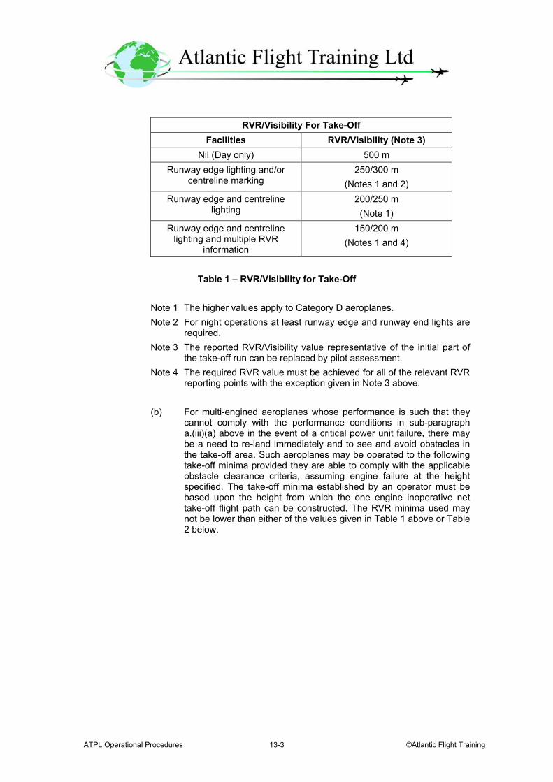
ATPL Operational Procedures ©Atlantic Flight Training 13-3
RVR/Visibility For Take-Off
Facilities RVR/Visibility (Note 3) Nil (Day only) 500 m
Runway edge lighting and/or centreline marking
250/300 m (Notes 1 and 2)
Runway edge and centreline lighting
200/250 m (Note 1)
Runway edge and centreline lighting and multiple RVR
information
150/200 m (Notes 1 and 4)
Table 1 – RVR/Visibility for Take-Off
Note 1 The higher values apply to Category D aeroplanes. Note 2 For night operations at least runway edge and runway end lights are required. Note 3 The reported RVR/Visibility value representative of the initial part of
the take-off run can be replaced by pilot assessment. Note 4 The required RVR value must be achieved for all of the relevant RVR
reporting points with the exception given in Note 3 above.
(b) For multi-engined aeroplanes whose performance is such that they cannot comply with the performance conditions in sub-paragraph a.(iii)(a) above in the event of a critical power unit failure, there may be a need to re-land immediately and to see and avoid obstacles in the take-off area. Such aeroplanes may be operated to the following take-off minima provided they are able to comply with the applicable obstacle clearance criteria, assuming engine failure at the height specified. The take-off minima established by an operator must be based upon the height from which the one engine inoperative net take-off flight path can be constructed. The RVR minima used may not be lower than either of the values given in Table 1 above or Table 2 below.
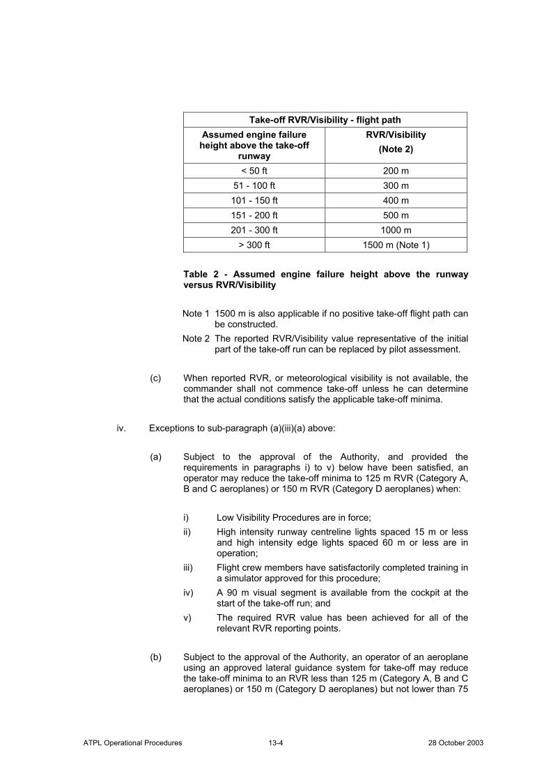
ATPL Operational Procedures 28 October 2003 13-4
Take-off RVR/Visibility - flight path
Assumed engine failure height above the take-off
runway
RVR/Visibility (Note 2)
< 50 ft 200 m 51 - 100 ft 300 m 101 - 150 ft 400 m 151 - 200 ft 500 m 201 - 300 ft 1000 m
> 300 ft 1500 m (Note 1)
Table 2 - Assumed engine failure height above the runway versus RVR/Visibility Note 1 1500 m is also applicable if no positive take-off flight path can
be constructed. Note 2 The reported RVR/Visibility value representative of the initial
part of the take-off run can be replaced by pilot assessment.
(c) When reported RVR, or meteorological visibility is not available, the commander shall not commence take-off unless he can determine that the actual conditions satisfy the applicable take-off minima.
iv. Exceptions to sub-paragraph (a)(iii)(a) above:
(a) Subject to the approval of the Authority, and provided the requirements in paragraphs i) to v) below have been satisfied, an operator may reduce the take-off minima to 125 m RVR (Category A, B and C aeroplanes) or 150 m RVR (Category D aeroplanes) when:
i) Low Visibility Procedures are in force; ii) High intensity runway centreline lights spaced 15 m or less and high intensity edge lights spaced 60 m or less are in operation; iii) Flight crew members have satisfactorily completed training in a simulator approved for this procedure; iv) A 90 m visual segment is available from the cockpit at the start of the take-off run; and v) The required RVR value has been achieved for all of the relevant RVR reporting points.
(b) Subject to the approval of the Authority, an operator of an aeroplane using an approved lateral guidance system for take-off may reduce the take-off minima to an RVR less than 125 m (Category A, B and C aeroplanes) or 150 m (Category D aeroplanes) but not lower than 75
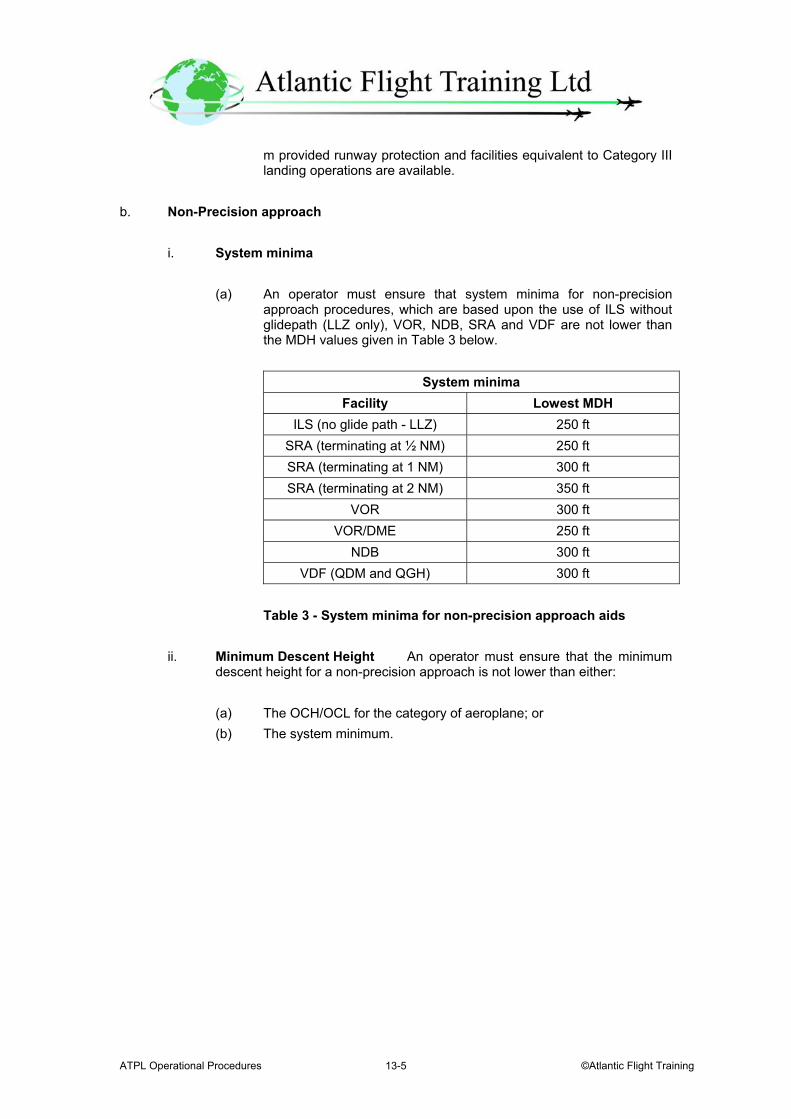
ATPL Operational Procedures ©Atlantic Flight Training 13-5
m provided runway protection and facilities equivalent to Category III landing operations are available.
b. Non-Precision approach
i. System minima
(a) An operator must ensure that system minima for non-precision approach procedures, which are based upon the use of ILS without glidepath (LLZ only), VOR, NDB, SRA and VDF are not lower than the MDH values given in Table 3 below.
System minima
Facility Lowest MDH ILS (no glide path - LLZ) 250 ft
SRA (terminating at ½ NM) 250 ft SRA (terminating at 1 NM) 300 ft SRA (terminating at 2 NM) 350 ft
VOR 300 ft VOR/DME 250 ft
NDB 300 ft VDF (QDM and QGH) 300 ft
Table 3 - System minima for non-precision approach aids
ii. Minimum Descent Height An operator must ensure that the minimum descent height for a non-precision approach is not lower than either:
(a) The OCH/OCL for the category of aeroplane; or (b) The system minimum.
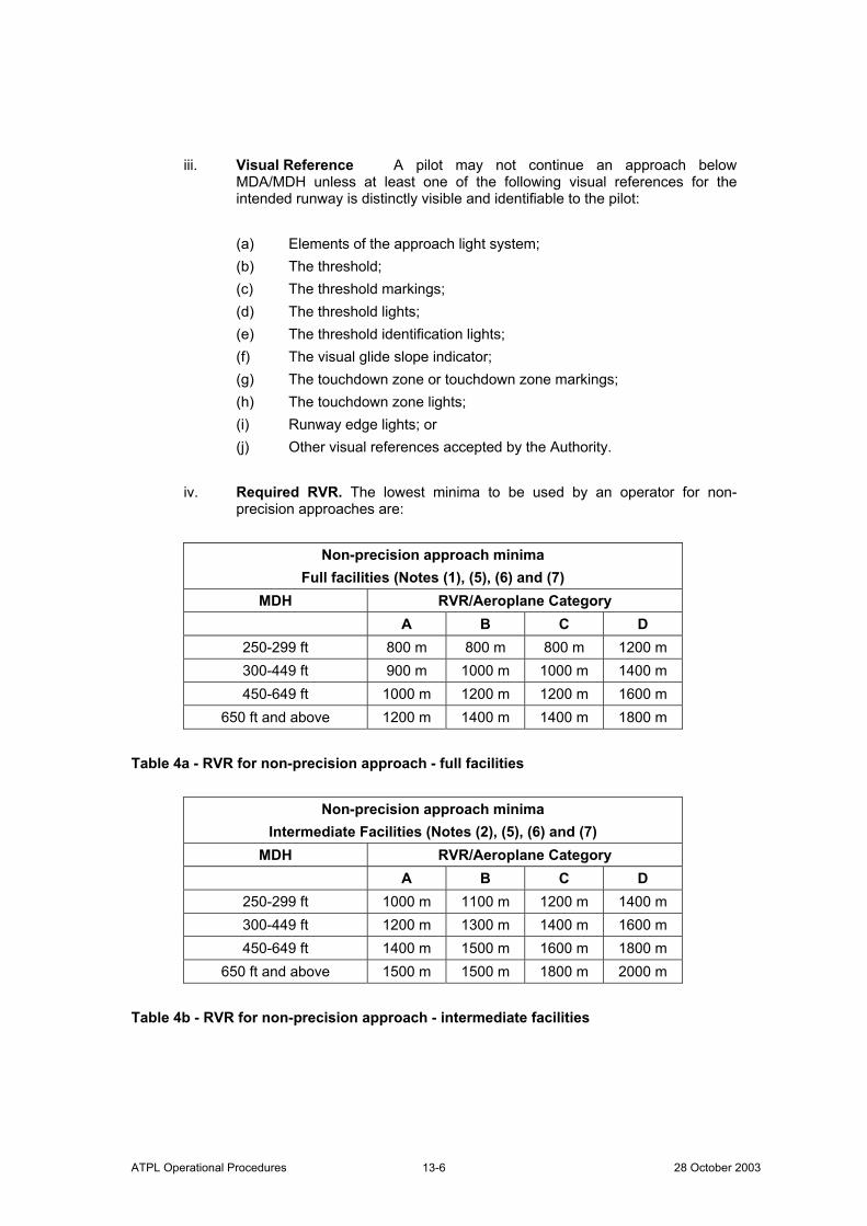
ATPL Operational Procedures 28 October 2003 13-6
iii. Visual Reference A pilot may not continue an approach below MDA/MDH unless at least one of the following visual references for the intended runway is distinctly visible and identifiable to the pilot:
(a) Elements of the approach light system; (b) The threshold; (c) The threshold markings; (d) The threshold lights; (e) The threshold identification lights; (f) The visual glide slope indicator; (g) The touchdown zone or touchdown zone markings; (h) The touchdown zone lights; (i) Runway edge lights; or (j) Other visual references accepted by the Authority.
iv. Required RVR. The lowest minima to be used by an operator for non-
precision approaches are:
Non-precision approach minima Full facilities (Notes (1), (5), (6) and (7)
MDH RVR/Aeroplane Category A B C D
250-299 ft 800 m 800 m 800 m 1200 m 300-449 ft 900 m 1000 m 1000 m 1400 m 450-649 ft 1000 m 1200 m 1200 m 1600 m
650 ft and above 1200 m 1400 m 1400 m 1800 m Table 4a - RVR for non-precision approach - full facilities
Non-precision approach minima Intermediate Facilities (Notes (2), (5), (6) and (7)
MDH RVR/Aeroplane Category A B C D
250-299 ft 1000 m 1100 m 1200 m 1400 m 300-449 ft 1200 m 1300 m 1400 m 1600 m 450-649 ft 1400 m 1500 m 1600 m 1800 m
650 ft and above 1500 m 1500 m 1800 m 2000 m Table 4b - RVR for non-precision approach - intermediate facilities
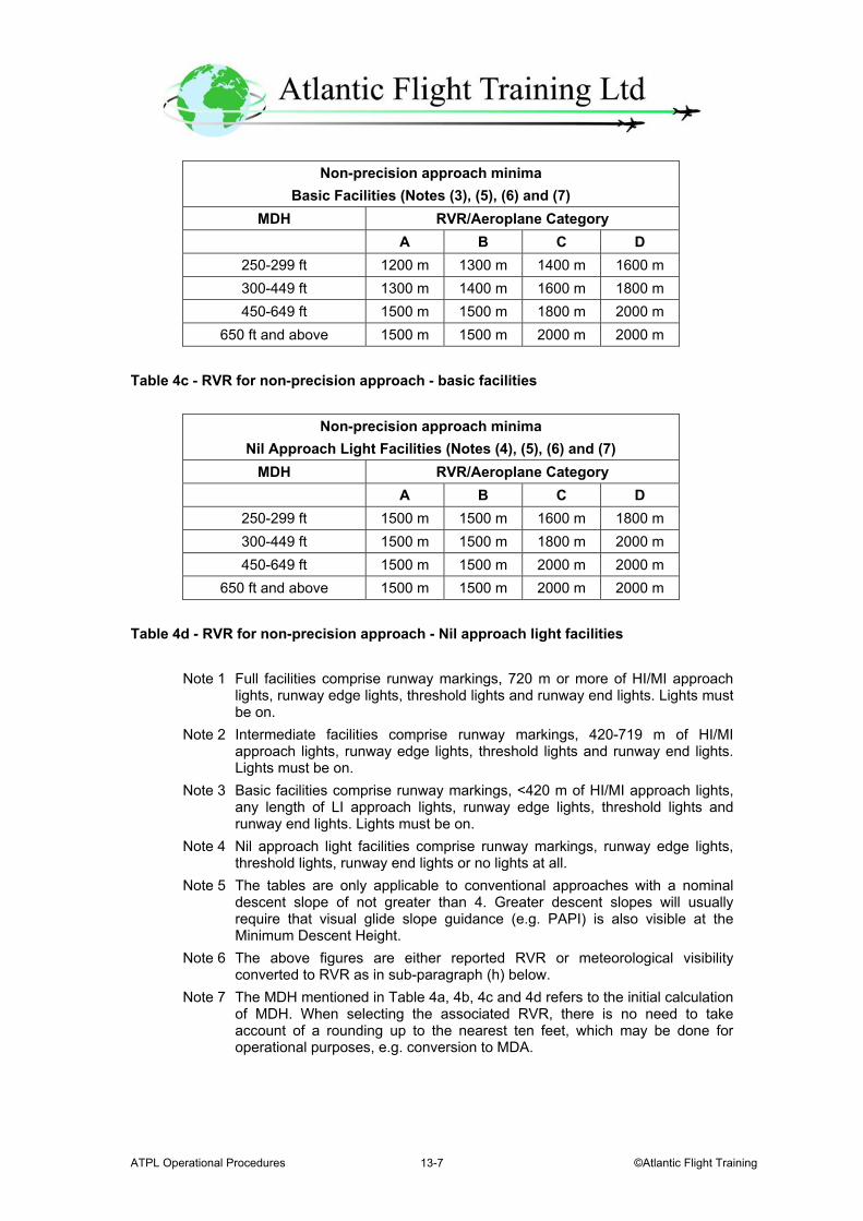
ATPL Operational Procedures ©Atlantic Flight Training 13-7
Non-precision approach minima Basic Facilities (Notes (3), (5), (6) and (7)
MDH RVR/Aeroplane Category A B C D
250-299 ft 1200 m 1300 m 1400 m 1600 m 300-449 ft 1300 m 1400 m 1600 m 1800 m 450-649 ft 1500 m 1500 m 1800 m 2000 m
650 ft and above 1500 m 1500 m 2000 m 2000 m Table 4c - RVR for non-precision approach - basic facilities
Non-precision approach minima Nil Approach Light Facilities (Notes (4), (5), (6) and (7)
MDH RVR/Aeroplane Category A B C D
250-299 ft 1500 m 1500 m 1600 m 1800 m 300-449 ft 1500 m 1500 m 1800 m 2000 m 450-649 ft 1500 m 1500 m 2000 m 2000 m
650 ft and above 1500 m 1500 m 2000 m 2000 m Table 4d - RVR for non-precision approach - Nil approach light facilities
Note 1 Full facilities comprise runway markings, 720 m or more of HI/MI approach lights, runway edge lights, threshold lights and runway end lights. Lights must be on. Note 2 Intermediate facilities comprise runway markings, 420-719 m of HI/MI approach lights, runway edge lights, threshold lights and runway end lights. Lights must be on. Note 3 Basic facilities comprise runway markings, <420 m of HI/MI approach lights, any length of LI approach lights, runway edge lights, threshold lights and runway end lights. Lights must be on. Note 4 Nil approach light facilities comprise runway markings, runway edge lights, threshold lights, runway end lights or no lights at all. Note 5 The tables are only applicable to conventional approaches with a nominal descent slope of not greater than 4. Greater descent slopes will usually require that visual glide slope guidance (e.g. PAPI) is also visible at the Minimum Descent Height. Note 6 The above figures are either reported RVR or meteorological visibility converted to RVR as in sub-paragraph (h) below. Note 7 The MDH mentioned in Table 4a, 4b, 4c and 4d refers to the initial calculation of MDH. When selecting the associated RVR, there is no need to take account of a rounding up to the nearest ten feet, which may be done for operational purposes, e.g. conversion to MDA.
ATPL Operational Procedures 28 October 2003 13-8
v. Night operations. For night operations at least runway edge, threshold and runway end lights must be on.
c. Precision approach - Category I operations
i. General A Category I operation is a precision instrument approach and landing using ILS, MLS or PAR with a decision height not lower than 200 ft and with a runway visual range not less than 550 m. ii. Decision Height An operator must ensure that the decision height to
be used for a Category I precision approach is not lower than:
(a) The minimum decision height specified in the Aeroplane Flight Manual (AFM) if stated; (b) The minimum height to which the precision approach aid can be used without the required visual reference; (c) The OCH/OCL for the category of aeroplane; or (d) 200 ft.
iii. Visual Reference A pilot may not continue an approach below the Category I decision height, determined in accordance with sub-paragraph c.(ii) above, unless at least one of the following visual references for the intended runway is distinctly visible and identifiable to the pilot:
(a) Elements of the approach light system; (b) The threshold; (c) The threshold markings; (d) The threshold lights; (e) The threshold identification lights; (f) The visual glide slope indicator; (g) The touchdown zone or touchdown zone markings; (h) The touchdown zone lights; or (i) Runway edge lights.
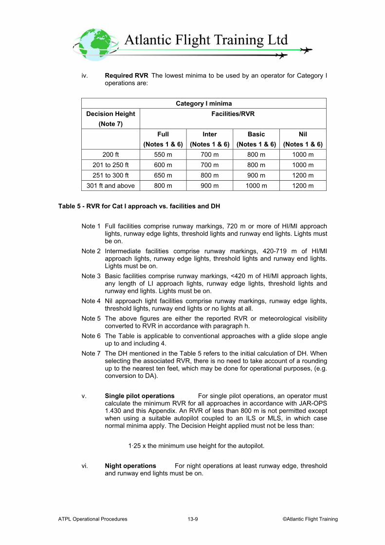
ATPL Operational Procedures ©Atlantic Flight Training 13-9
iv. Required RVR The lowest minima to be used by an operator for Category I operations are:
Category I minima
Decision Height (Note 7)
Facilities/RVR
Full (Notes 1 & 6)
Inter (Notes 1 & 6)
Basic (Notes 1 & 6)
Nil (Notes 1 & 6)
200 ft 550 m 700 m 800 m 1000 m 201 to 250 ft 600 m 700 m 800 m 1000 m 251 to 300 ft 650 m 800 m 900 m 1200 m
301 ft and above 800 m 900 m 1000 m 1200 m Table 5 - RVR for Cat I approach vs. facilities and DH
Note 1 Full facilities comprise runway markings, 720 m or more of HI/MI approach lights, runway edge lights, threshold lights and runway end lights. Lights must be on.
Note 2 Intermediate facilities comprise runway markings, 420-719 m of HI/MI approach lights, runway edge lights, threshold lights and runway end lights. Lights must be on.
Note 3 Basic facilities comprise runway markings, <420 m of HI/MI approach lights, any length of LI approach lights, runway edge lights, threshold lights and runway end lights. Lights must be on. Note 4 Nil approach light facilities comprise runway markings, runway edge lights,
threshold lights, runway end lights or no lights at all. Note 5 The above figures are either the reported RVR or meteorological visibility converted to RVR in accordance with paragraph h. Note 6 The Table is applicable to conventional approaches with a glide slope angle up to and including 4. Note 7 The DH mentioned in the Table 5 refers to the initial calculation of DH. When selecting the associated RVR, there is no need to take account of a rounding up to the nearest ten feet, which may be done for operational purposes, (e.g. conversion to DA).
v. Single pilot operations For single pilot operations, an operator must calculate the minimum RVR for all approaches in accordance with JAR-OPS 1.430 and this Appendix. An RVR of less than 800 m is not permitted except when using a suitable autopilot coupled to an ILS or MLS, in which case normal minima apply. The Decision Height applied must not be less than:
1·25 x the minimum use height for the autopilot. vi. Night operations For night operations at least runway edge, threshold
and runway end lights must be on.
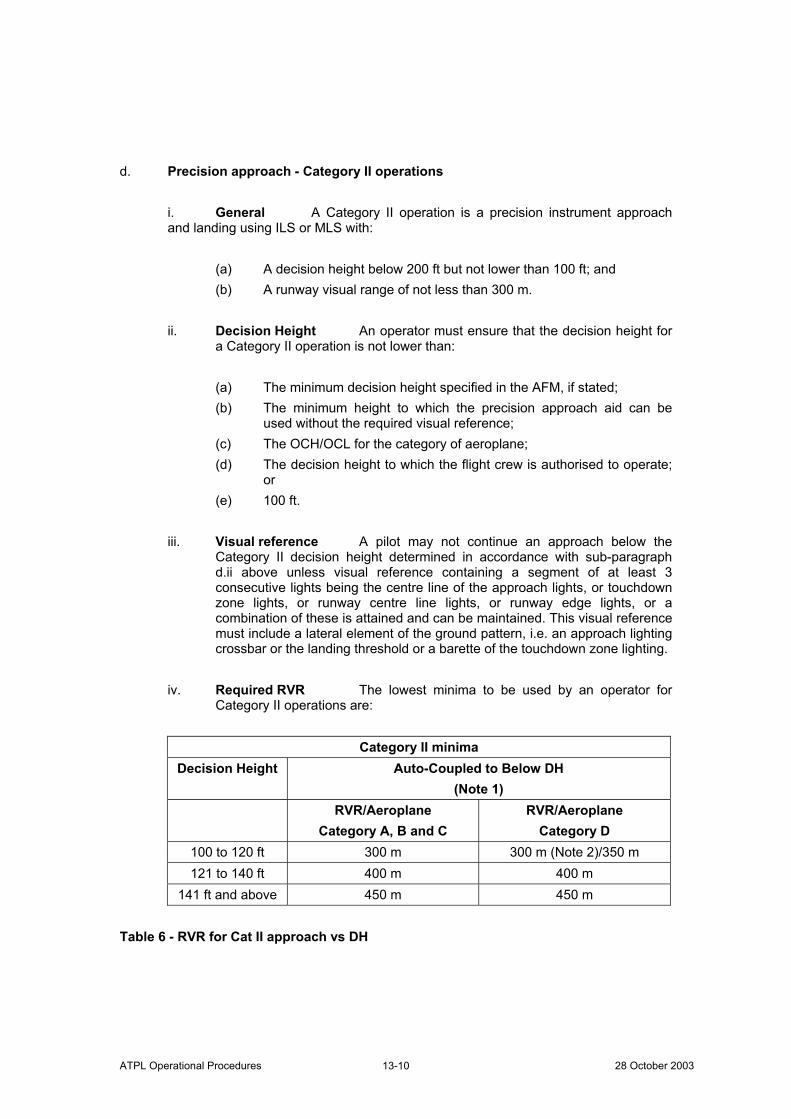
ATPL Operational Procedures 28 October 2003 13-10
d. Precision approach - Category II operations
i. General A Category II operation is a precision instrument approach and landing using ILS or MLS with:
(a) A decision height below 200 ft but not lower than 100 ft; and (b) A runway visual range of not less than 300 m.
ii. Decision Height An operator must ensure that the decision height for a Category II operation is not lower than:
(a) The minimum decision height specified in the AFM, if stated; (b) The minimum height to which the precision approach aid can be used without the required visual reference; (c) The OCH/OCL for the category of aeroplane; (d) The decision height to which the flight crew is authorised to operate; or (e) 100 ft.
iii. Visual reference A pilot may not continue an approach below the Category II decision height determined in accordance with sub-paragraph d.ii above unless visual reference containing a segment of at least 3 consecutive lights being the centre line of the approach lights, or touchdown zone lights, or runway centre line lights, or runway edge lights, or a combination of these is attained and can be maintained. This visual reference must include a lateral element of the ground pattern, i.e. an approach lighting crossbar or the landing threshold or a barette of the touchdown zone lighting.
iv. Required RVR The lowest minima to be used by an operator for
Category II operations are:
Category II minima Decision Height Auto-Coupled to Below DH
(Note 1) RVR/Aeroplane
Category A, B and C RVR/Aeroplane
Category D 100 to 120 ft 300 m 300 m (Note 2)/350 m 121 to 140 ft 400 m 400 m
141 ft and above 450 m 450 m Table 6 - RVR for Cat II approach vs DH
ATPL Operational Procedures ©Atlantic Flight Training 13-11
Note 1 The reference to 'auto-coupled to below DH' in this table means continued use of the automatic flight control system down to a height which is not greater than 80% of the applicable DH. Thus airworthiness requirements may, through minimum engagement height for the automatic flight control system, affect the DH to be applied. Note 2 300 m may be used for a Category D aeroplane conducting an autoland.
e. Precision approach - Category III operations
i. General Category III operations are subdivided as follows:
(a) Category III A operations A precision instrument approach and landing using ILS or MLS with:
i) A decision height lower than 100 ft; and ii) A runway visual range not less than 200 m.
(b) Category III B operations A precision instrument approach and landing using ILS or MLS with:
i) A decision height lower than 50 ft, or no decision height; and ii) A runway visual range lower than 200 m but not less than 75 m.
Note Where the decision height (DH) and runway visual range
(RVR) do not fall within the same Category, the RVR will determine in which Category the operation is to be considered.
ii Decision Height For operations in which a decision height is used, an operator must ensure that the decision height is not lower than:
(a) The minimum decision height specified in the AFM, if stated; (b) The minimum height to which the precision approach aid can be used without the required visual reference; or (c) The decision height to which the flight crew is authorised to operate.
iii. No Decision Height Operations Operations with no decision height may only be conducted if:
(a) The operation with no decision height is authorised in the AFM; (b) The approach aid and the aerodrome facilities can support operations with no decision height; and (c) The operator has an approval for CAT III operations with no decision height.
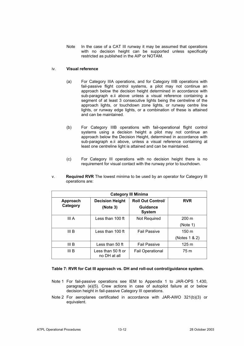
ATPL Operational Procedures 28 October 2003 13-12
Note In the case of a CAT III runway it may be assumed that operations with no decision height can be supported unless specifically restricted as published in the AIP or NOTAM.
iv. Visual reference
(a) For Category IIIA operations, and for Category IIIB operations with fail-passive flight control systems, a pilot may not continue an approach below the decision height determined in accordance with sub-paragraph e.ii above unless a visual reference containing a segment of at least 3 consecutive lights being the centreline of the approach lights, or touchdown zone lights, or runway centre line lights, or runway edge lights, or a combination of these is attained and can be maintained. (b) For Category IIIB operations with fail-operational flight control
systems using a decision height a pilot may not continue an approach below the Decision Height, determined in accordance with sub-paragraph e.ii above, unless a visual reference containing at least one centreline light is attained and can be maintained.
(c) For Category III operations with no decision height there is no requirement for visual contact with the runway prior to touchdown.
v. Required RVR The lowest minima to be used by an operator for Category III operations are:
Category III Minima
Approach Category
Decision Height (Note 3)
Roll Out Control/ Guidance System
RVR
III A Less than 100 ft Not Required 200 m (Note 1)
III B Less than 100 ft Fail Passive 150 m (Notes 1 & 2)
III B Less than 50 ft Fail Passive 125 m III B Less than 50 ft or
no DH at all Fail Operational 75 m
Table 7: RVR for Cat III approach vs. DH and roll-out control/guidance system.
Note 1 For fail-passive operations see IEM to Appendix 1 to JAR-OPS 1.430,
paragraph (e)(5). Crew actions in case of autopilot failure at or below decision height in fail-passive Category III operations.
Note 2 For aeroplanes certificated in accordance with JAR-AWO 321(b)(3) or equivalent.
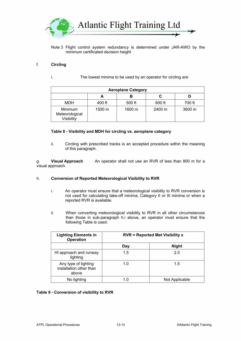
ATPL Operational Procedures ©Atlantic Flight Training 13-13
Note 3 Flight control system redundancy is determined under JAR-AWO by the minimum certificated decision height
f. Circling
i. The lowest minima to be used by an operator for circling are:
Aeroplane Category A B C D
MDH 400 ft 500 ft 600 ft 700 ft Minimum
Meteorological Visibility
1500 m 1600 m 2400 m 3600 m
Table 8 - Visibility and MDH for circling vs. aeroplane category ii. Circling with prescribed tracks is an accepted procedure within the meaning of this paragraph.
g. Visual Approach An operator shall not use an RVR of less than 800 m for a visual approach. h. Conversion of Reported Meteorological Visibility to RVR
i. An operator must ensure that a meteorological visibility to RVR conversion is not used for calculating take-off minima, Category II or III minima or when a reported RVR is available. ii. When converting meteorological visibility to RVR in all other circumstances than those in sub-paragraph h.i above, an operator must ensure that the following Table is used:
Lighting Elements in
Operation RVR = Reported Met Visibility x
Day Night HI approach and runway
lighting 1.5 2.0
Any type of lighting installation other than
above
1.0 1.5
No lighting 1.0 Not Applicable Table 9 - Conversion of visibility to RVR
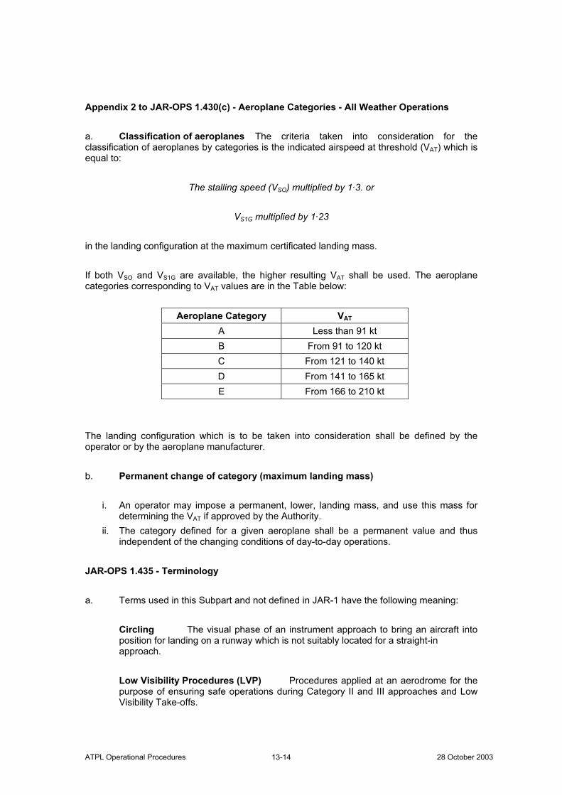
ATPL Operational Procedures 28 October 2003 13-14
Appendix 2 to JAR-OPS 1.430(c) - Aeroplane Categories - All Weather Operations a. Classification of aeroplanes The criteria taken into consideration for the classification of aeroplanes by categories is the indicated airspeed at threshold (VAT) which is equal to:
The stalling speed (VSO) multiplied by 1·3. or
VS1G multiplied by 1·23 in the landing configuration at the maximum certificated landing mass. If both VSO and VS1G are available, the higher resulting VAT shall be used. The aeroplane categories corresponding to VAT values are in the Table below:
Aeroplane Category VAT
A Less than 91 kt B From 91 to 120 kt C From 121 to 140 kt D From 141 to 165 kt E From 166 to 210 kt
The landing configuration which is to be taken into consideration shall be defined by the operator or by the aeroplane manufacturer. b. Permanent change of category (maximum landing mass)
i. An operator may impose a permanent, lower, landing mass, and use this mass for determining the VAT if approved by the Authority. ii. The category defined for a given aeroplane shall be a permanent value and thus independent of the changing conditions of day-to-day operations.
JAR-OPS 1.435 - Terminology a. Terms used in this Subpart and not defined in JAR-1 have the following meaning:
Circling The visual phase of an instrument approach to bring an aircraft into position for landing on a runway which is not suitably located for a straight-in approach. Low Visibility Procedures (LVP) Procedures applied at an aerodrome for the purpose of ensuring safe operations during Category II and III approaches and Low Visibility Take-offs.
ATPL Operational Procedures ©Atlantic Flight Training 13-15
Low Visibility Take-Off (LVTO) A take-off where the Runway Visual Range (RVR) is less than 400 m. Flight control system A system which includes an automatic landing system and/or a hybrid landing system. Fail-Passive flight control system A flight control system is fail-passive if, in the event of a failure, there is no significant out-of-trim condition or deviation of flight path or attitude but the landing is not completed automatically. For a fail-passive automatic flight control system the pilot assumes control of the aeroplane after a failure.
Fail-Operational flight control system A flight control system is fail-operational if, in the event of a failure below alert height, the approach, flare and landing, can be completed automatically. In the event of a failure, the automatic landing system will operate as a fail-passive system. Fail-operational hybrid landing system A system which consists of a primary fail-passive automatic landing system and a secondary independent guidance system enabling the pilot to complete a landing manually after failure of the primary system.
Note A typical secondary independent guidance system consists of a monitored head-up display providing guidance which normally takes the form of command information but it may alternatively be situation (or deviation) information.
Visual approach An approach when either part or all of an instrument approach procedure is not completed and the approach is executed with visual reference to the terrain.
JAR-OPS 1.440 - Low Visibility Operations - General Operating Rules a. An operator shall not conduct Category II or III operations unless:
i. Each aeroplane concerned is certificated for operations with decision heights below 200 ft, or no decision height, and equipped in accordance with JAR- AWO or an equivalent accepted by the Authority; ii. A suitable system for recording approach and/or automatic landing success and failure is established and maintained to monitor the overall safety of the operation; iii. The operations are approved by the Authority; iv. The flight crew consists of at least 2 pilots; and v. Decision Height is determined by means of a radio altimeter.
ATPL Operational Procedures 28 October 2003 13-16
b. An operator shall not conduct low visibility take-offs in less than 150 m RVR (Category A, B and C aeroplanes) or 200 m RVR (Category D aeroplanes) unless approved by the Authority.
Appendix 1 to JAR-OPS 1.440 - Low Visibility Operations - General Operating Rules a. General The following procedures apply to the introduction and approval of
low visibility operations. b. Airborne Systems Operational Demonstration An operator must comply
with the following requirements in order to determine or validate the use and effectiveness of the applicable:
Aircraft flight guidance systems Training Flight crew procedures Maintenance programme Manuals for Category II/III operations
To establish approval:
At least 30 approaches and landings must be accomplished using the Category II/III systems installed in each aircraft type if the requested DH is 50 ft or higher
At least 100 approaches and landings must be accomplished using the Category II/III systems installed in each aircraft type if the requested DH is less than 50 ft
A change to the above figures can be approved by the authority If the number of unsuccessful approaches exceeds 5% of the total then the evaluation programme is extended in 10 approach and landing steps until the failure rate is less than 5%. c. Data Collection for Operational Demonstrations An approved method of data
collection has to be used. d. Data Analysis Unsatisfactory approaches must be documented and analysed
ATPL Operational Procedures ©Atlantic Flight Training 13-17
e. Continuous Monitoring After approval the operations must be continuously monitored. The following information must be retained for a period of 12 months:
The total number of Category II/III approaches Reports of unsatisfactory approaches documented in the following four
categories: Airborne equipment faults Ground facility difficulties Missed approaches because of ATC instructions Other reasons
f. Transitional Periods
Operators with no previous Category II/III experience Initial approval is for Category II/IIIA operations having gained at least 6 months Category I experience on the aeroplane type After completing 6 months Category II/IIIA operations the operator may be approved for Category IIIB operations. Higher minima than those published may be imposed for a period of time. Operators with no previous Category II/III experience These operators may obtain a reduced transition period
g. Maintenance of Category II, Category III and LVTO equipment
Maintenance instructions for the on-board guidance systems must be established by the operator, in liaison with the manufacturer, and included in the operator's aeroplane maintenance programme prescribed in JAR-OPS 1.910 which must be approved by the Authority.
JAR-OPS 1.445 - Low Visibility Operations - Aerodrome Considerations a. An operator shall not use an aerodrome for Category II or III operations unless the
aerodrome is approved for such operations by the State in which the aerodrome is located.
b. An operator shall verify that Low Visibility Procedures (LVP) have been established,
and will be enforced, at those aerodromes where low visibility operations are to be conducted.
ATPL Operational Procedures 28 October 2003 13-18
JAR-OPS 1.450 - Low Visibility Operations - Training and Qualifications a. An operator shall ensure that, prior to conducting Low Visibility Take-Off, Category II
and III operations:
i. Each flight crew member:
(a) Completes the training and checking requirements prescribed in Appendix 1 including simulator training in operating to the limiting values of RVR and Decision Height appropriate to the operator's Category II/III approval; and (b) Is qualified in accordance with Appendix 1;
ii. The training and checking is conducted in accordance with a detailed syllabus approved by the Authority and included in the Operations Manual. This training is in addition to that prescribed in JAR-OPS 1, Subpart N; and
b. The flight crew qualification is specific to the operation and the aeroplane type. JAR-OPS 1.455 - Low Visibility Operations - Operating Procedures a. An operator must establish procedures and instructions to be used for Low Visibility
Take-Off and Category II and III operations. These procedures must be included in the Operations Manual and contain the duties of flight crew members during taxying, take-off, approach, flare, landing, roll-out and missed approach as appropriate.
b. The commander shall satisfy himself that:
i. The status of the visual and non-visual facilities is sufficient prior to commencing a Low Visibility Take-Off or a Category II or III approach; ii. Appropriate LVPs are in force according to information received from Air Traffic Services, before commencing a Low Visibility Take-off or a Category II or III approach; and iii. The flight crew members are properly qualified prior to commencing a Low Visibility Take-off in an RVR of less than 150 m (Category A, B and C aeroplanes) or 200 m (Cat D aeroplanes) or a Category II or III approach.
JAR-OPS 1.460 - Low Visibility Operations - Minimum Equipment a. An operator must include in the Operations Manual the minimum equipment that has
to be serviceable at the commencement of a Low Visibility Take-off or a Category II or III approach in accordance with the AFM or other approved document.
b. The commander shall satisfy himself that the status of the aeroplane and of the
relevant airborne systems is appropriate for the specific operation to be conducted.
ATPL Operational Procedures ©Atlantic Flight Training 13-19
JAR-OPS 1.465 – VFR Operating Minima The operator ensures that:
a. VFR flights are conducted in accordance with the table below. b. Special VFR flights are not commenced when the visibility is less than 3 km and are
not conducted when the visibility is less than 1.5 km. Appendix 1 to JAR-OPS 1.465 - Minimum Visibilities for VFR Operations Airspace Classification
B CDE F & G
Above 900 m (3000 ft) AMSL or above 300 m (1000 ft) above terrain, whichever is the higher
At and below 900 m (3000 ft) AMSL or 300 m (1000 ft) above terrain, whichever is the higher
Distance from cloud
Clear of cloud 1500 m horizontally 300 m (1000 ft) vertically
Clear of cloud and in sight of the surface
Flight visibility 8 km at and above 3050 m (10 000 ft) AMSL (Note 1) 5 km below 3050 m (10 000 ft) AMSL
5 km (Note 2)
Note 1 When the height of the transition altitude is lower than 3050 m (10 000 ft) AMSL, FL 100 should be used in lieu of 10 000ft. Note 2 Cat A and B aeroplanes may be operated in flight visibilities down to 3000 m, provided the appropriate ATS authority permits use of a flight visibility less than 5 km, and the circumstances are such, that the probability of encounters with other traffic is low, and the IAS is 140 kt or less. JAR-OPS 1.340 - Meteorological Conditions On an IFR Flight the commander shall not:
Commence take-off, or Continue beyond the point from which a revised flight plan applies in the event of
in-flight replanning unless information indicates that the expected weather at the destination and/or the required alternates are at or above the planning minima.
ATPL Operational Procedures 28 October 2003 13-20
On an IFR flight the commander shall not continue beyond:
The decision point, or The pre-determined point, when using pre-determined point procedure
unless information indicates that the expected weather at the destination and/or the required alternates are at or above the planning minima. An IFR flight shall not continue towards the planned destination unless the latest information indicates that at the ETA the weather conditions at:
The destination, or At least one destination alternate
Are at or above the applicable aerodrome operating minima. VFR flights shall not be commenced unless the current meteorological reports and forecasts indicate that the flight along the route can be flown under VFR. JAR-OPS 1.405 - Commencement and Continuation of Approach The pilot of a flight can commence an instrument approach regardless of the reported RVR/Visibility. The approach shall not be continued beyond the outer marker or equivalent position if the reported RVR/Visibility is less than the minima required in IEM – OPS 1.405a. If the aircraft has passed the outer marker and the RVR falls below the applicable minima then the approach may be continued to DA/DH or MDA/MDH as applicable. Where RVR is not available then the RVR values are derived using the reported visibility. If no outer marker or equivalent position exists then the pilot shall make the decision to continue or abandon the approach before descending below 1000 ft above the aerodrome on the final approach segment. Where the MDA/MDH is at or above 1000 ft above the aerodrome the operator will establish a height below which the aeroplane is not to descend. The approach may be continued below DA/DH or MDA/MDH and the landing completed provided that the required visual reference is established.
ATPL Operational Procedures ©Atlantic Flight Training 13-21
The touchdown zone RVR is always controlling. Where the reported and relevant mid point and stop end RVRs are also controlling then the following apply (Relevant means that part of the runway used during the high speed phase of the landing to a speed of approximately 60 knots):
The minimum value for the mid point is 125 m or the required RVR value for the touch down zone if less, and
75 m for the stop end Where an aeroplane is fitted with a roll out guidance or control system the minimum value for the mid point RVR is 75 m. Appendix 1 to JAR-OPS 1.375 - In-flight Fuel Management
In-flight Fuel Checks The commander ensures that fuel checks are carried out during flight at regular intervals. The remaining fuel is recorded to:
compare actual with planned consumption check that the fuel remaining is sufficient to complete the flight determine the expected fuel remaining at the destination
In-flight Fuel Management Where an in-flight fuel check shows that the remaining fuel will be less than the required alternate fuel plus final reserve the commander must assess the traffic, operational conditions prevailing at:
the destination aerodrome along the diversion route to an alternate aerodrome, and at the destination alternate aerodrome
when deciding to proceed to destination or to divert so as to land with not less than the final reserve Flight to an Isolated Aerodrome The last point of diversion to any available en-route aerodrome has to be determined. Before reaching this point the commander must assess:
the fuel expected overhead the isolated aerodrome the weather conditions the traffic and operational conditions prevailing
before deciding whether to proceed to the isolated aerodrome or divert.
ATPL Operational Procedures 28 October 2003 13-22
JAR-OPS 1.510 – Landing - Destination and Alternate Aerodromes The landing mass of an aeroplane must not exceed the maximum landing mass specified for the altitude and the ambient temperature expected for the estimated time of landing. Where the missed approach gradient is greater than 2.5% then the operator must verify that the expected landing mass allows the missed approach with a climb gradient equal to or greater than the applicable missed approach gradient in the one-engine inoperative configuration and speed. Where a DH is less than 200 ft the operator must verify that the landing mass allows a missed approach gradient of climb, with the critical engine failed, at the speed and configuration for go-around of at least 2.5%. Use of alternate methods to the above can only be approved by the authority.
ATPL Operational Procedures ©Atlantic Flight Training 14-1
Chapter 14.
Instrument and Equipment Requirements JAR-OPS 1.635 - Circuit Protection Devices In an aeroplane where fuses are used the number of spare fuses available for use in flight must be equal to:
i. At least 10% of the number of fuses of each rating, or ii. Three of each rating whichever is the greater.
JAR-OPS 1.640 - Aeroplane Operating Lights An operator cannot operate an aeroplane unless it is equipped with: a. For flight by day:
i. Anti-collision light system; ii. Lighting supplied from the aeroplane's electrical system to provide adequate illumination for all instruments and equipment essential to the safe operation of the aeroplane; iii. Lighting supplied from the aeroplane's electrical system to provide illumination in all passenger compartments; and iv. An electric torch for each required crew member readily accessible to crew members when seated at their designated station.
b. For flight by night, in addition to the equipment specified above:
i. Navigation/position lights; and ii. Two landing lights or a single light having two separately supplied filaments;
JAR-OPS 1.645 - Windshield Wipers An aeroplane with a maximum certificated take-off mass of more than 5700 kg must be equipped with a windshield wiper or equivalent for each pilot station.
ATPL Operational Procedures 28 October 2003 14-2
JAR-OPS 1.650 - Day VFR Operations - Flight and Navigational Instruments and Associated Equipment An aeroplane flying day VFR must have the following flight and navigational equipment:
Magnetic compass An accurate timepiece showing the time in hours, minutes and seconds A sensitive pressure altimeter calibrated in feet with a sub-scale setting calibrated
in hPa adjustable for any pressure likely to be set in flight An airspeed indicator calibrated in knots A vertical speed indicator A turn and slip indicator or a turn coordinator incorporating a slip indicator An attitude indicator A stabilised direction indicator An outside air temperature gauge visible to the crew
Where two pilots are required the second pilot’s station shall have the following separate instruments:
A sensitive pressure altimeter calibrated in feet with a sub-scale setting calibrated in hPa adjustable for any pressure likely to be set in flight
An airspeed indicator calibrated in knots A vertical speed indicator A turn and slip indicator or a turn coordinator incorporating a slip indicator An attitude indicator A stabilised direction indicator
For flights that:
do not exceed 60 minutes duration that take-off and land at the same aerodrome, and that remain within 50 nm of the aerodrome
A turn and slip indicator, or a turn coordinator incorporating a slip indicator or both an attitude indicator and a slip indicator can replace the following instruments:
A turn and slip indicator or a turn coordinator incorporating a slip indicator An attitude indicator A stabilised direction indicator
ATPL Operational Procedures ©Atlantic Flight Training 14-3
For aeroplanes:
With a maximum certificated take-off mass in excess of 5700 kg or have a passenger seating configuration of more than 9
First issued with a C of A on or after 1 April 1999 The airspeed indicating system must be equipped with a pitot heat system or equivalent. Where duplicate instruments are required then separate displays are provided. All aeroplanes must be fitted with a system that shows when power is not adequately supplied. Aircraft with compressibility limitations not indicated by the required airspeed indicators must have a Mach Number Indicator. Day VFR operations cannot be conducted unless the aeroplane is equipped with a headset with boom microphone or equivalent for each flight crew member. JAR-OPS 1.652 - IFR or Night Operations - Flight and Navigation Instruments and Associated Equipment IFR or night flights must have the following:
Magnetic compass An accurate timepiece showing the time in hours, minutes and seconds Two sensitive pressure altimeters calibrated in feet with a sub-scale setting
calibrated in hPa adjustable for any pressure likely to be set in flight. A three pointer altimeter is not acceptable.
An airspeed indicator calibrated in knots with heated pitot system including a warning system (This does not apply to aircraft of maximum certificated take-off mass of 5700 kg or less with a maximum seating capacity of 9 or less where the C of A was first issued before 1 April 1998).
A vertical speed indicator A turn and slip indicator An attitude indicator A stabilised direction indicator An outside air temperature gauge visible to the crew Two independent static pressure systems (Propeller driven aircraft of maximum
certificated take-off mass of 5700 kg or less are allowed one static pressure system and one alternate source of static pressure).
ATPL Operational Procedures 28 October 2003 14-4
Where two pilots are required the second pilot’s station requires the following:
A sensitive pressure altimeter calibrated in feet with a sub-scale setting calibrated in hPa adjustable for any pressure likely to be set in flight. A three pointer altimeter is not acceptable.
An airspeed indicator calibrated in knots with heated pitot system including a warning system (This does not apply to aircraft of maximum certificated take-off mass of 5700 kg or less with a maximum seating capacity of 9 or less where the C of A was first issued before 1 April 1998).
A vertical speed indicator A turn and slip indicator An attitude indicator A stabilised direction indicator
Where the maximum certificated take-off mass is greater than 5700 kg and the passenger seating configuration is more than 9 seats then the aircraft must be equipped with an additional standby attitude indicator (artificial horizon) capable of being used from either pilot station that:
Is powered continuously during normal operation and after a total failure of the normal electrical system is powered from an independent source
Provides reliable information for a minimum of 30 minutes after a failure Operates independently of other attitude indicating systems Operates automatically after a failure Is appropriately illuminated
Where the standby indicator is certified under JAR 25 the turn and slip indicators may be replaced by slip indicators. The aircraft must also be fitted with:
A chart holder which must also be illuminated and in an easily readable position A means of indicating when power is not being supplied correctly
Aircraft with compressibility limitations not indicated by the required airspeed indicators must have a Mach Number Indicator. Day VFR operations cannot be conducted unless the aeroplane is equipped with a headset with boom microphone or equivalent for each flight crewmember.
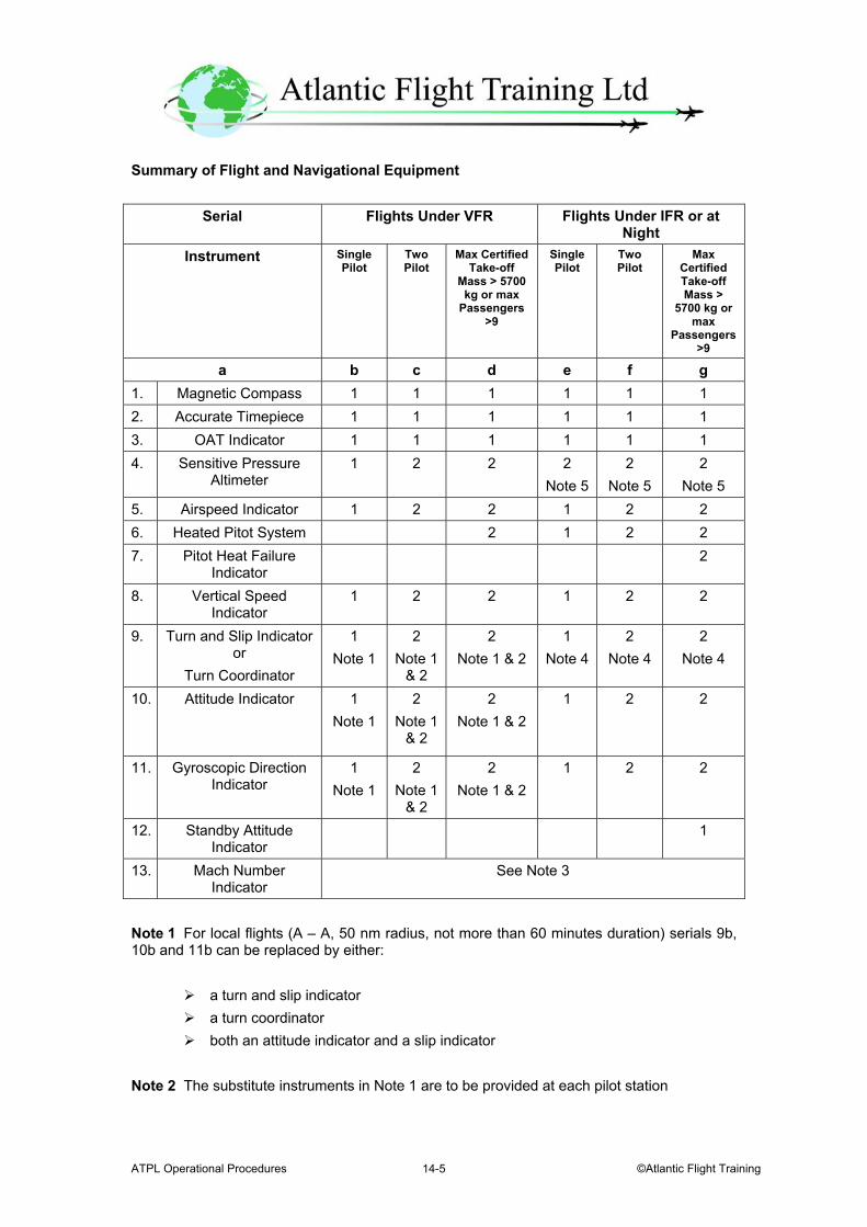
ATPL Operational Procedures ©Atlantic Flight Training 14-5
Summary of Flight and Navigational Equipment
Serial Flights Under VFR Flights Under IFR or at Night
Instrument Single Pilot
Two Pilot
Max Certified Take-off
Mass > 5700 kg or max
Passengers >9
Single Pilot
Two Pilot
Max Certified Take-off Mass >
5700 kg or max
Passengers >9
a b c d e f g 1. Magnetic Compass 1 1 1 1 1 1 2. Accurate Timepiece 1 1 1 1 1 1 3. OAT Indicator 1 1 1 1 1 1 4. Sensitive Pressure
Altimeter 1 2 2 2
Note 52
Note 5 2
Note 5 5. Airspeed Indicator 1 2 2 1 2 2 6. Heated Pitot System 2 1 2 2 7. Pitot Heat Failure
Indicator 2
8. Vertical Speed Indicator
1 2 2 1 2 2
9. Turn and Slip Indicator or
Turn Coordinator
1 Note 1
2 Note 1
& 2
2 Note 1 & 2
1 Note 4
2 Note 4
2 Note 4
10. Attitude Indicator 1 Note 1
2 Note 1
& 2
2 Note 1 & 2
1 2 2
11. Gyroscopic Direction Indicator
1 Note 1
2 Note 1
& 2
2 Note 1 & 2
1 2 2
12. Standby Attitude Indicator
1
13. Mach Number Indicator
See Note 3
Note 1 For local flights (A – A, 50 nm radius, not more than 60 minutes duration) serials 9b, 10b and 11b can be replaced by either:
a turn and slip indicator a turn coordinator both an attitude indicator and a slip indicator
Note 2 The substitute instruments in Note 1 are to be provided at each pilot station
ATPL Operational Procedures 28 October 2003 14-6
Note 3 A Mach Number Indicator is required whenever compressibility limitations are not otherwise indicated by airspeed indicators Note 4 For IFR at night a turn and slip indicator or a slip indicator and a third standby attitude indicator certified to JAR 25 is required Note 5 Three pointer or drum pointer altimeters do no not satisfy the requirement JAR-OPS 1.660 - Altitude Alerting System a. The operator cannot operate a turbine propeller powered aeroplane with a maximum certificated take-off mass in excess of 5700 kg or having a maximum approved passenger seating configuration of more than 9 seats or a turbojet powered aeroplane unless it is equipped with an altitude alerting system capable of:
i. Alerting the flight crew upon approaching a pre-selected altitude; and ii. Alerting the flight crew by at least an aural signal, when deviating from a pre-
selected altitude, Aeroplanes with a maximum certificated take-off mass of 5700 kg or less having a maximum approved passenger seating configuration of more than 9 and first issued with an individual certificate of airworthiness in a JAA Member State or elsewhere before 1 April 1972 and already registered in a JAA Member State on 1 April 1995 are exempted. JAR-OPS 1.665 - Ground Proximity Warning System The operator shall not operate:
a. A turbine powered aeroplane having a maximum certificated take-off mass in excess of 5700 kg or a maximum approved passenger seating configuration of more than 9 unless it is equipped with a ground proximity warning system
b. A turbine powered aeroplane having a maximum certificated take-off mass in
excess of 15 000 kg or a maximum approved passenger seating configuration of more than 30 on or after:
1 October 2001 for aeroplanes first issued with a C of A on or
after this date, or 1 January 2005 for aeroplanes first issued with a C of A before 1
October 2001
unless it is equipped with a GPWS system that includes a Terrain Avoidance and Warning System –TAWS
ATPL Operational Procedures ©Atlantic Flight Training 14-7
c. A turbine powered aeroplane having a maximum certificated take-off mass in excess of 5700 kg but not more than 15 000 kg or a maximum approved passenger seating configuration of more then 9 but not more than 30 on or after:
1 January 2003 for aeroplanes first issued with a C of A on or
after this date, or 1 October 2001 for aeroplanes which are not already equipped
with a GPWS
unless it is equipped with a GPWS system that includes a Terrain Avoidance and Warning System –TAWS
The ground proximity warning system required by this paragraph must automatically provide, by means of aural signals, which can be supplemented by visual signals, warning to the flight crew of:
i. Sink rate ii. Ground proximity iii. Altitude loss after take-off or go-around iv. Incorrect landing configuration and v. Downward glideslope deviation.
The TAWS must automatically provide the Flight Crew by means of aural and visual signals and a Terrain Awareness Display with sufficient alerting time to prevent controlled flight into terrain events and provide a forward looking capability and terrain clearance floor JAR-OPS 1.668 - Airborne Collision Avoidance System An operator shall not operate a turbine powered aeroplane:
Having a maximum certificated take-off mass in excess of 15 000 kg or a maximum approved seating configuration of more than 30 after 1 January 2000, or
Having a maximum certificated take-off mass in excess of 5700 kg but not more than 15 000 kg, or a maximum approved passenger seating configuration of more then 19 but not more than 30 after 1 January 2005 unless,
It is equipped with a minimum performance level of at least ACAS II.

ATPL Operational Procedures 28 October 2003 14-8
JAR-OPS 1.670 - Airborne Weather Radar Equipment a. The operator cannot operate:
i. A pressurised aeroplane; or ii. An unpressurised aeroplane which has a maximum certificated take-off mass of more than 5700 kg; or iii. An unpressurised aeroplane having a maximum approved passenger seating configuration of more than 9 seats after 1 April 1999,
unless it is equipped with airborne weather radar equipment whenever such an aeroplane is being operated at night or in instrument meteorological conditions in areas where thunderstorms or other potentially hazardous weather conditions, regarded as detectable with airborne weather radar, may be expected to exist along the route. b. For a propeller driven pressurised aeroplane, having a maximum certificated take-off mass not exceeding 5700 kg with a maximum approved passenger seating configuration not exceeding 9 seats, the airborne weather radar equipment may be replaced by other equipment capable of detecting thunderstorms and other potentially hazardous weather conditions subject to approval by the Authority. JAR-OPS 1.690 - Crew Member Interphone System a. The operator cannot operate an aeroplane with a maximum certificated take-off mass exceeding 15 000 kg or having a maximum approved passenger seating configuration of more than 19 unless it is equipped with a crew member interphone system. Aeroplanes first issued with an individual certificate of airworthiness in a JAA member State or elsewhere before 1 April 1965 and already registered in a JAA member State on 1 April 1995 are exempt. b. The crew member interphone system required must:
i. Operate independently of the public address system except for handsets, headsets, microphones, selector switches and signalling devices; ii. Provide a means of two-way communication between the flight crew compartment and:
(a) Each passenger compartment; (b) Each galley located other than on a passenger deck level; and (c) Each remote crew compartment that is not on the passenger deck
and is not easily accessible from a passenger compartment;
iii. Be readily accessible for use from each of the required flight crew stations in the flight crew compartment;
ATPL Operational Procedures ©Atlantic Flight Training 14-9
iv. Be readily accessible for use at required cabin crew member stations close to each separate or pair of floor level emergency exits; v. Have an alerting system incorporating aural or visual signals for use by flight crew members to alert the cabin crew and for use by cabin crew members to alert the flight crew; vi. Have a means for the recipient of a call to determine whether it is a normal call or an emergency call; and vii. Provide on the ground a means of two-way communication between ground
personnel and at least two flight crew members. JAR-OPS 1.735 - Internal Doors and Curtains The operator must ensure that the following equipment is installed: a. In an aeroplane with a maximum approved passenger seating configuration of more than 19 passengers, a door between the passenger compartment and the flight deck compartment with:
i. A sign stating 'crew only' and ii. A means of locking to prevent passengers from opening it without the
permission of a member of the flight crew; b. A means for opening each door that separates a passenger compartment from another compartment that has emergency exit provisions. The means for opening must be readily accessible; c. If it is necessary to pass through a doorway or curtain separating the passenger cabin from other areas to reach any required emergency exit from any passenger seat, the door or curtain must have a means to secure it in the open position; d. A sign on each internal door or adjacent to a curtain that is the means of access to a passenger emergency exit, to indicate that it must be secured open during take off and landing; and e. A means for any member of the crew to unlock any door that is normally accessible to passengers and that can be locked by passengers. JAR-OPS 1.760 - First Aid Oxygen A pressurised aeroplane shall not be operated above 25 000 ft when a cabin crew member is required to be carried unless it is equipped with a supply of undiluted oxygen for passengers who for physiological reasons might require oxygen following a cabin depressurisation . The amount of oxygen is calculated using an average flow rate of 3 litres per minute. The amount has to be sufficient for the remainder of the flight after depressurisation when the cabin altitude exceeds 8000 ft but does not exceed 15 000 ft for at least 2% of the
ATPL Operational Procedures 28 October 2003 14-10
passengers (In no case may this be less than one). There must be a minimum of two dispensing units with a means for the cabin crew to use the equipment as well. The amount required for a particular operation is determined on cabin pressure altitudes and flight duration. The equipment has to be capable of generating a mass flow to each user of at least 4 litres per minute. The equipment may be fitted with a device to reduce this flow to 2 litres per minute at any altitude.
IEM-OPS 1.760 - First Aid Oxygen
First aid oxygen is provided for those passengers who require oxygen after supplemental oxygen has been exhausted.
The calculation of the amount of first aid oxygen required takes into account that after a depressurisation the supplemental oxygen should be sufficient to cope with:
All passengers when the cabin altitude is above 15 000 ft A proportion of the passengers when the cabin altitude is between 10 000 ft and
15 000 ft. After depressurisation an emergency descent should be carried out to the lowest altitude compatible with safety. The aircraft should land at the nearest available airfield at the earliest opportunity. JAR-OPS 1.855 - Audio Selector Panel An aeroplane cannot be operated under IFR unless it is equipped with an audio selector panel accessible to each required flight crew member. JAR-OPS 1.860 - Radio Equipment for Operations Under VFR Over Routes Navigated by Reference to Visual Landmarks The operator cannot operate an aeroplane under VFR over routes that can be navigated by reference to visual landmarks, unless it is equipped with the radio equipment, communication and SSR transponder equipment necessary for the following following:
i. Communicate with appropriate ground stations; ii. Communicate with appropriate air traffic control facilities from any
point in controlled airspace within which flights are intended; and iii. Receive meteorological information;
ATPL Operational Procedures ©Atlantic Flight Training 14-11
JAR-OPS 1.865 - Communication and Navigation Equipment for Operations Under IFR, or Under VFR Over Routes Not Navigated by Reference to Visual Landmarks a. An operator cannot operate an aeroplane under IFR, or under VFR over routes that cannot be navigated by reference to visual landmarks, unless the aeroplane is equipped with radio (communication and SSR transponder) and navigation equipment required by the appropriate ATS authority. b. Radio equipment. The operator ensures that radio equipment comprises not less than:
i. Two independent radio communication systems necessary under normal operating conditions to communicate with an appropriate ground station from any point on the route including diversions;
c. Navigation equipment. The operator ensures that navigation equipment
1. Comprises not less than:
i One VOR receiving system, one ADF system, one DME; ii One ILS or MLS where ILS or MLS is required for approach
navigation purposes; iii One Marker Beacon receiving system where a Marker Beacon is required for approach navigation purposes; iv An Area Navigation System when area navigation is required for the route being flown; v An additional DME system on any route where navigation is based only on DME signals; vi An additional VOR receiving system on any route where navigation is based only on VOR signals; and vii An additional ADF system on any route where navigation is based only on NDB signals, or
2 Complies with the Required Navigation Performance (RNP) Type for operation in the airspace concerned.
d. An operator may operate an aeroplane that is not equipped with the navigation equipment above, provided that it is equipped with alternative equipment by the Authority. The reliability and the accuracy of alternative equipment must allow safe navigation for the intended route. e. The operator has to ensure that the VHF communications equipment, ILS Localiser and VOR Receivers installed on aircraft to be operated in IFR comply with the FM immunity performance standards.
ATPL Operational Procedures 28 October 2003 14-12
JAR-OPS 1.866 - Transponder Equipment An operator cannot operate an aeroplane unless it is equipped with:
A pressure altitude reporting SSR transponder, and Any other SSR transponder required for the route being flown
JAR-OPS 1.870 - Additional Navigation Equipment for Operations in MNPS Airspace Regional Supplementary Procedures Doc 7030 specifies the minimum equipment required. The navigation equipment must be visible and usable by the pilot seated at his duty station. JAR-OPS 1.870 - Equipment for Operation in Defined Airspace with RVSM Aeroplanes operating in RVSM airspace must be equipped with:
Two independent altitude measurement systems An altitude alerting system An automatic altitude control system An SSR with altitude reporting system that can be connected to the altitude
measurement system in use for altitude keeping
ATPL Operational Procedures ©Atlantic Flight Training 15-1
Chapter 15.
Aeroplane Maintenance
JAR-OPS 1.880 - Terminology The following definitions from JAR-145 apply to Aeroplane Maintenance:
Preflight inspection means the inspection carried out before flight to ensure that the aeroplane is fit for the intended flight. It does not include defect rectification.
Approved standard means a manufacturing/design/maintenance/quality standard approved by the Authority.
Approved by the Authority means approved by the Authority directly or in accordance with a procedure approved by the Authority.
JAR-OPS 1.885 - Application for and Approval of the Operator's Maintenance System a. For the approval of the maintenance system, an applicant for the initial issue, variation and renewal of an AOC have to submit the following documents:
i. The operator’s Maintenance Management Exposition ii. The operator’s maintenance contract between the operator and a JAR 145
approved organisation iii. The aeroplane technical log iv. The technical specifications of ii above v. The number of aeroplanes
JAR-OPS 1.895 - Maintenance Management a. An operator must be approved in accordance with JAR-145 – Approved Maintenance Organisations in order to carry out the maintenance requirements. An exception is when the Authority is satisfied that the maintenance can be contracted to an appropriate JAR-145 approved/accepted organisation. b. The operator must employ personnel acceptable to the Authority to ensure that all maintenance is carried out on time to an approved. c. The operator must provide suitable office accommodation at appropriate locations for the maintenance personnel.
ATPL Operational Procedures 28 October 2003 15-2
JAR-OPS 1.900 - Quality System a. For maintenance purposes, the operator's quality system must include the following functions in addition to the normal requirements:
i. Monitoring that the activities are being performed in accordance with the accepted procedures; ii. Monitoring that all contracted maintenance is carried out in accordance with the contract; and iii. Monitoring the continued compliance with the requirements of this Subpart.
JAR-OPS 1.905 - Operator's Maintenance Management Exposition a. The operator must provide an operator's Maintenance Management exposition containing details of the organisation structure including:
i. The nominated postholder responsible for the maintenance system; ii. The procedures that must be followed to satisfy the maintenance responsibility of the operator, except that where the operator is approved as a maintenance organisation in accordance with JAR-145, the details may be included in the JAR-145 exposition.
b. The operator's maintenance management exposition and any amendments have to be approved by the Authority. JAR-OPS 1.910 - Operator's Aeroplane Maintenance Programme a. The aeroplane must be maintained in accordance with the operator's aeroplane maintenance programme. The programme contains details of all maintenance required to be carried out. The programme has to include a reliability programme when required by the Authority. b. The operator's aeroplane maintenance programme and any amendments have to be approved by the Authority. JAR-OPS 1.930 - Continued Validity of the Air Operator Certificate in Respect of the Maintenance System The operator must comply with the General Rules for an AOC to ensure continued validity of the air operator's certificate in respect of the maintenance system.
ATPL Operational Procedures ©Atlantic Flight Training 15-3
JAR-OPS 1.935 - Equivalent Safety Case No alternative procedures can be introduced to those prescribed unless needed and an equivalent safety case has first been approved by the Authority and supported by JAA Member Authorities.

ATPL Operational Procedures 28 October 2003 15-4
Intentionally Left Blank
ATPL Operational Procedures ©Atlantic Flight Training 16-1
Chapter 16.
Navigation for Long Range Flights JAR-OPS 1.240 - Routes and Areas of Operation a. An operator has to ensure that operations are only conducted along such routes or in areas, for which:
i. Ground facilities and services, including meteorological services, are provided which are adequate for the planned operation; ii. The performance of the aeroplane intended to be used is adequate to comply with minimum flight altitude requirements; iii. The equipment of the aeroplane intended to be used meets the minimum requirements for the planned operation; iv. Appropriate maps and charts are available; v. If two-engined aeroplanes are used, adequate aerodromes are available within the time/distance limitations. vi. If single-engine aeroplanes are used, surfaces are available which permit a safe forced landing to be executed.
b. The operations have to comply with any restriction on the routes or the areas of operation, imposed by the Authority. JAR-OPS 1.290 - Flight Preparation a. The operator ensures that an operational flight plan is completed for each intended flight. b. The commander cannot commence a flight unless he is satisfied that:
i. The aeroplane is airworthy; ii. The aeroplane is not operated contrary to the provisions of the Configuration Deviation List (CDL); iii. The instruments and equipment required for the flight are available; iv. The instruments and equipment are in operable condition except as provided in the MEL; v. Those parts of the operations manual which are required for the flight are available; vi. The documents, additional information and forms required are on board; vii. Current maps, charts and associated documentation or equivalent data are available to cover the intended operation of the aeroplane including any diversion which may reasonably be expected; viii. Ground facilities and services required for the planned flight are available and adequate;
ATPL Operational Procedures 28 October 2003 16-2
ix. The provisions specified in the operations manual in respect of fuel, oil and oxygen requirements, minimum safe altitudes, aerodrome operating minima and availability of alternate aerodromes, where required, can be complied with for the planned flight; x. The load is properly distributed and safely secured; xi. The mass of the aeroplane, at the commencement of take-off roll, will be such that the flight is within the specified performance limitations; and xii. Any operational limitation in addition to those covered by sub-paragraphs (ix) and (xi) above can be complied with.
JAR-OPS 1.220 - Authorisation of Aerodromes by Operators The operator can only authorise the use of aerodromes that are adequate for the type of aeroplane and operation concerned. IEM OPS 1.220 - Authorisation of Aerodromes When choosing an aerodrome the operator should take account of the following:
Adequate Aerodrome An adequate aerodrome is an aerodrome which the operator considers to be satisfactory, taking account of the applicable performance requirements and runway characteristics. In addition, it should be anticipated that, at the expected time of use, the aerodrome will be available and equipped with necessary ancillary services, such as ATS, sufficient lighting, communications, weather reporting, navaids and emergency services.
a. For an ETOPS en-route alternate aerodrome, the following additional points should be considered.
i. The availability of an ATC facility; and ii. The availability of at least one letdown aid (ground radar is acceptable) for an instrument approach.
JAR-OPS 1.241 - Operation in Defined Airspace with Reduced Vertical Separation Minima (RVSM) An operator cannot operate an aeroplane without RVSM approval where the vertical separation minimum of 300m (1000ft) applies unless approved to do so by the Authority.
ATPL Operational Procedures ©Atlantic Flight Training 16-3
JAR-OPS 1.243 - Operation in Areas with Specific Navigation Performance Requirements An operator cannot operate aeroplanes in MNPS, RNP or RNAV airspace without the approval of the authority. JAR-OPS 1.245 - Maximum Distance from an Adequate Aerodrome for Two-Engined Aeroplanes without an ETOPS Approval a. Unless specifically approved by the Authority in accordance with ETOPS Approval, an operator cannot operate a two-engined aeroplane over a route which contains a point further from an adequate aerodrome than, in the case of:
Performance Class A aeroplanes with either: i. A maximum approved passenger seating configuration of 20 or more; or ii. A maximum take-off mass of 45 360kg or more, the distance flown in 60 minutes at the one-engine-inoperative cruise speed determined in accordance with subparagraph (b) below;
Performance Class A aeroplanes with either: i. A maximum approved passenger seating configuration of 19 or less; or ii. A maximum take-off mass of less than 45 360kg, the distance flown in 120 minutes, or if approved by the authority up to 180 minutes for turbojet aeroplanes, at the one-engine-inoperative cruise speed determined in accordance with subparagraph (b) below; Performance Class B or C aeroplanes:
i. The distance flown in 120 minutes at the one-engine-inoperative cruise
speed determined in accordance with subparagraph (b) below; or ii. 300 nautical miles, whichever is less.
ATPL Operational Procedures 28 October 2003 16-4
b. The operator determines a speed for the calculation of the maximum distance to an adequate aerodrome for each two-engined aeroplane type operated, not exceeding VMO, based upon the true airspeed that the aeroplane can maintain with one-engine-inoperative under the following conditions:
1. International Standard Atmosphere (ISA); 2. Level flight:
i. For turbojet aeroplanes at:
FL 170; or At the maximum flight level to which the aeroplane, with one
engine inoperative, can climb, and maintain, using the gross rate of climb specified in the AFM, whichever is less.
ii. For propeller driven aeroplanes at:
FL 80; or At the maximum flight level to which the aeroplane, with one
engine inoperative, can climb, and maintain, using the gross rate of climb specified in the AFM, whichever is less.
3. Maximum continuous thrust or power on the remaining operating engine; 4. An aeroplane mass not less than that resulting from:
i Take-off at sea-level at maximum take-off mass; and ii All engines climb to the optimum long range cruise altitude; and iii All engines cruise at the long range cruise speed at this altitude, until
the time elapsed since take-off is equal to the applicable threshold prescribed above.
c. The operator must ensure that the following data is included in the Operations Manual:
1. The one-engine-inoperative cruise speed determined in accordance with b above; and 2. The maximum distance from an adequate aerodrome determined in accordance with a and b above.
Note: The speeds and altitudes (flight levels) specified above are only intended to be used for establishing the maximum distance from an adequate aerodrome.
ATPL Operational Procedures ©Atlantic Flight Training 16-5
JAR-OPS 1.060 - Ditching The operator cannot operate an aeroplane with an approved passenger seating configuration of more than 30 passengers on overwater flights at a distance from land suitable for making an emergency landing:
Greater than 120 minutes at cruising speed, or 400 nautical miles,
whichever is the lesser, unless the aeroplane complies with the ditching requirements prescribed in the applicable airworthiness code.
Performance Class A JAR-OPS 1.500 - En-route - One Engine Inoperative a. The operator ensures that with one engine inoperative an aeroplane flies above the minimum en-route altitude along the planned route. The net flight path must have a positive gradient at 1500 ft above the aerodrome where the landing is made after engine failure. If ice protection systems are required, the effect of their use on the net flight path must be taken into account. b. The gradient of the net flight path must be positive at least 1000 ft above all terrain and obstructions along the route within 9.3 km (5 nm) on either side of the intended track. c. The net flight path must permit the aeroplane to continue flight from the cruising altitude to an aerodrome where a landing can be made. The net flight path must clear vertically, by at least 2000 ft, all terrain and obstructions along the route within 9.3 km (5 nm) on either side of the intended track with regard to the conditions set out below:
i. The engine is assumed to fail at the most critical point along the route; ii. Account is taken of the effects of winds on the flight path; iii. Fuel jettisoning is permitted to an extent consistent with reaching the aerodrome with the required fuel reserves, if a safe procedure is used; and iv. The aerodrome where the aeroplane is assumed to land after engine failure must meet the following criteria:
(a) The performance requirements at the expected landing mass are met; and (b) Weather reports or forecasts, or any combination thereof, and field condition reports indicate that a safe landing can be accomplished at the estimated time of landing.
d. Where the navigation accuracy cannot meet the 95% containment level an operator can increase the width margins to 18.5 km (10 nm).
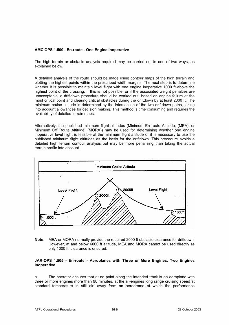
ATPL Operational Procedures 28 October 2003 16-6
AMC OPS 1.500 - En-route - One Engine Inoperative The high terrain or obstacle analysis required may be carried out in one of two ways, as explained below. A detailed analysis of the route should be made using contour maps of the high terrain and plotting the highest points within the prescribed width margins. The next step is to determine whether it is possible to maintain level flight with one engine inoperative 1000 ft above the highest point of the crossing. If this is not possible, or if the associated weight penalties are unacceptable, a driftdown procedure should be worked out, based on engine failure at the most critical point and clearing critical obstacles during the driftdown by at least 2000 ft. The minimum cruise altitude is determined by the intersection of the two driftdown paths, taking into account allowances for decision making. This method is time consuming and requires the availability of detailed terrain maps. Alternatively, the published minimum flight altitudes (Minimum En route Altitude, (MEA), or Minimum Off Route Altitude, (MORA)) may be used for determining whether one engine inoperative level flight is feasible at the minimum flight altitude or it is necessary to use the published minimum flight altitudes as the basis for the driftdown. This procedure avoids a detailed high terrain contour analysis but may be more penalising than taking the actual terrain profile into account.
Note: MEA or MORA normally provide the required 2000 ft obstacle clearance for driftdown. However, at and below 6000 ft altitude, MEA and MORA cannot be used directly as only 1000 ft. clearance is ensured. JAR-OPS 1.505 - En-route - Aeroplanes with Three or More Engines, Two Engines Inoperative a. The operator ensures that at no point along the intended track is an aeroplane with three or more engines more than 90 minutes, at the all-engines long range cruising speed at standard temperature in still air, away from an aerodrome at which the performance
ATPL Operational Procedures ©Atlantic Flight Training 16-7
requirements applicable at the expected landing mass are met unless it complies with the details set out below. b. The two engines inoperative en-route net flight path data must permit the aeroplane to continue the flight, in the expected meteorological conditions, from the point where two engines are assumed to fail simultaneously, to an aerodrome at which it is possible to land safely. The net flight path must clear vertically, by at least 2000 ft all terrain and obstructions along the route within 9.3 km (5 nm) on either side of the intended track. If ice protection systems are used then the effect of their use on the net flight path data must be taken into account. If the navigational accuracy does not meet the 95% containment level, an operator must increase the width margin to 18.5 km (10 nm). c. The two engines are assumed to fail at the most critical point of the route where the aeroplane is more than 90 minutes, at the all engines long range cruising speed at standard temperature in still air, away from an aerodrome at which the performance requirements are met. d. The net flight path must have a positive gradient at 1500 ft above the aerodrome where the landing is assumed to be made after the failure of two engines. e. Fuel jettisoning is permitted if a safe procedure is used. f. The expected mass of the aeroplane at the point where the two engines are assumed to fail must not be less than that which would include sufficient fuel to proceed to an aerodrome where the landing is assumed to be made, and to arrive there at least 1500 ft directly over the landing area and thereafter to fly level for 15 minutes. Performance Class B JAR-OPS 1.540 - En-Route - Multi-engined aeroplanes a. The operator ensures that the aeroplane in the event of an engine failure, can fly above the relevant minimum altitudes for safe flight stated in the Operations Manual to a point 1000 ft above an aerodrome. b. The following must be complied with:
i. The aeroplane is flying at an altitude where the rate of climb equals 300 ft per minute with all engines operating. ii. The en-route gradient with one engine inoperative shall be the gross gradient of descent or climb respectively increased or decreased by a gradient of 0.5%.
ATPL Operational Procedures 28 October 2003 16-8
JAR-OPS 1.542 - En-route - Single-Engine Aeroplanes a. The aeroplane must be capable of reaching a place where a safe forced landing can be made. For landplanes, a place on land is required. This point should be 100 ft above the intended landing area. b. The following limitations must be applied:
i. The aeroplane is flying at an altitude where the rate of climb is less than 300 ft per minute; and ii. The assumed en-route gradient shall be the gross gradient of descent increased by a gradient of 0·5%.
Performance Class C JAR-OPS 1.575 - En-Route - All Engines Operating a. The aeroplane must be capable of a rate of climb of at least 300 ft per minute with all engines operating and be able to satisfy the engine inoperative limitations. JAR-OPS 1.580 - En-Route - One Engine Inoperative a. The operator ensures that the aeroplane will, in the event of a failure at any point on its route or on any planned diversion and with the other engine or engines operating, be capable of continuing the flight from the cruising altitude to an aerodrome where a landing can be made clearing obstacles within 9.3 km (5 nm) either side of the intended track by a vertical interval of at least:
(1) 1000 ft when the rate of climb is zero or greater; or (2) 2000 ft when the rate of climb is less than zero.
b. The flight path must have a positive slope at an altitude of 450 m (1500 ft) above the aerodrome where the landing is assumed to be made after the failure of one engine. c. The available rate of climb of the aeroplane is taken to be 150 ft per minute less than the gross rate of climb specified. d. The width margins are increased to 18.5 km (10 nm) if the navigational accuracy does not meet the 95% containment level. e. Fuel jettisoning is permitted if a safe procedure is used.
ATPL Operational Procedures ©Atlantic Flight Training 16-9
JAR-OPS 1.585 - En-Route - Aeroplanes with Three or More Engines, Two Engines Inoperative a. At no point along the intended track, will an aeroplane with three or more engines be more than 90 minutes at the all-engine long range cruising speed at standard temperature in still air, away from an aerodrome at which the performance requirements applicable at the expected landing mass are met unless it complies with the paragraphs below. b. The two-engines inoperative flight path shown must permit the aeroplane to continue the flight clearing all obstacles within 9.3 km (5 nm) either side of the intended track by a vertical interval of at least 2000 ft, to an aerodrome at which the performance requirements are met. c. The two engines are assumed to fail at the most critical point of that portion of the route where the aeroplane is more than 90 minutes away from an aerodrome at which the performance requirements applicable at the expected landing mass are met. d. The expected mass of the aeroplane at the point where the two engines are assumed to fail must not be less than that which would include sufficient fuel to proceed to an aerodrome where the landing is assumed to be made, and to arrive there at an altitude of a least 450 m (1500 ft) directly over the landing area and thereafter to fly level for 15 minutes. e. The available rate of climb of the aeroplane shall be taken to be 150 ft per minute less than that specified. f. The width margins are increased to 18·5 km (10 nm) if the navigational accuracy does not meet the 95% containment level. g. Fuel jettisoning is permitted as long as the aircraft can reach the aerodrome with the required fuel reserves. A safe procedure must be used. AMC OPS 1.580 - En-Route - One Engine Inoperative Performance B aeroplanes have the same restrictions as Performance Class A aeroplanes. JAR-OPS 1.295 - Selection of Aerodromes a. The operator establishes procedures for the selection of destination and/or alternate aerodromes. b. A take-off alternate is specified in the operational flight plan if it is not possible to return to the aerodrome of departure for meteorological or performance reasons. The take-off alternate must be located within:
i. For two-engined aeroplanes in accordance with the AFM in still air standard conditions based on the actual take-off mass:
ATPL Operational Procedures 28 October 2003 16-10
(a) One hour flight time at a one-engine-inoperative cruising speed; or (b) The operators approved ETOPS diversion time up to a maximum of two hours at the one-engine-inoperative cruising speed; or
ii. Two hours flight time at a one-engine-inoperative cruising speed in still air standard conditions based on the actual take-off mass for three and four- engined aeroplanes; and iii. If the AFM does not contain a one-engine-inoperative cruising speed, the speed to be used for calculation must be that which is achieved with the remaining engine(s) set at maximum continuous power.
c. The operator must select at least one destination alternate for each IFR flight unless:
i. Both:
(a) The duration of the planned flight from take-off to landing does not exceed 6 hours; and (b) Two separate runways are available at the destination and the
meteorological conditions prevailing are such that, for the period from one hour before until one hour after the expected time of arrival at destination, the ceiling will be at least 2000 ft or the circling height + 500 ft whichever is the greater. Visibility must be at least 5 km.; or
ii. The destination is isolated and no adequate destination alternate exists.
d. An operator must select two destination alternates when:
i. The appropriate weather reports or forecasts for the destination indicate that during a period commencing 1 hour before and ending 1 hour after the estimated time of arrival, the weather conditions will be below the applicable planning minima; or ii. No meteorological information is available.
AMC-OPS 1.295 - Location of an En-Route Alternate Aerodrome The en-route alternate should be located within a circle having a radius equal to 20% of the total flight plan distance:
the centre of which lies on the planned routes at a distance from the destination of 25% of the total flight plan distance, or
at least 20% of the total flight plan distance plus 50 nm
whichever is the greater.
ATPL Operational Procedures ©Atlantic Flight Training 16-11
All distances are to be calculated for still air conditions. JAR-OPS 1.297 - Planning Minima for IFR Flights a. Planning minima for take-off alternates. When selecting an alternate aerodrome the appropriate weather reports for a period commencing 1 hour before and ending 1 hour after the estimated time of arrival indicate the weather conditions will be at or above the applicable landing minima. The ceiling must be taken into account when the only approaches available are non-precision and/or circling approaches. Limitations related to one engine inoperative operations must be taken into account. b. Planning minima for destination and destination alternate aerodromes. When selecting the destination aerodrome and/or destination alternate aerodrome(s) for 1 hour before and ending 1 hour after the estimated time of arrival at the aerodrome, the weather conditions will be at or above the applicable planning minima as follows:
i. Planning minima for a destination aerodrome:
(a) RVR/visibility comply with the Aerodrome Operating Minima; and (b) For a non-precision approach or a circling approach, the ceiling at or above MDH; and
ii. Planning minima for destination alternate aerodrome(s):
Type of approach Planning Minima
Cat II and III Cat I (Note 1) Cat I Non-precision
(Notes 1 and 2) Non-precision Non-precision
(Notes 1 and 2) plus 200 ft/1000 m
Circling Circling
Table 1 Planning minima - En-route and destination alternates
Note 1 RVR. Note 2 The ceiling must be at or above the MDH.
c. Planning minima for an en-route alternate aerodrome. When selecting an
aerodrome as an en-route alternate aerodrome the appropriate weather reports indicate that, for a period commencing 1 hour before and ending 1 hour after the expected time of arrival at the aerodrome, the weather conditions will be at or above the planning minima above.
ATPL Operational Procedures 28 October 2003 16-12
Separate Runways Runways on the same aerodrome can be considered to be separate when:
They are separate landing surfaces which may overlay or cross such that if one runway is blocked it will not prevent the planned type of operations on the other runway, and
Each of the landing surfaces has a separate approach procedure based on a separate aid
d. Planning minima for an ETOPS en-route alternate. When selecting ETOPS en-route alternate aerodrome unless the appropriate weather reports or forecasts for a period commencing 1 hour before and ending 1 hour after the expected time of arrival at the aerodrome, the weather conditions will be at or above the planning minima prescribed below, and in accordance with the operator's ETOPS approval.
Type of Approach Planning Minima (RVR/visibility required and ceiling if applicable)
Aerodrome with at least 2 separate approach
procedures based on 2 separate aids serving 2
separate runways
at least 2 separate approach procedures based on 2 separate aids serving 1
runway
or
at least 1 approach procedure based on 1 aid
serving 1 runway Precision Approach Cat II, III
(ILS, MLS) Precision Approach Cat I
Minima Non-Precision Approach
Minima
Precision Approach Cat I (ILS, MLS)
Non-Precision Approach Minima
Circling minima or, if not available, non-precision
approach minima plus 200 ft/1000 m
Non-Precision Approach The lower of non-precision approach minima plus 200 ft/1000 m or circling minima
The higher of circling minima or non-precision approach minima plus 200 ft/1000 m
Circling Approach Circling Minima Table 2 Planning minima – ETOPS JAR-OPS 1.225 - Aerodrome Operating Minima a. The operator specifies aerodrome operating minima for each departure, destination or alternate aerodrome authorised to be used.
ATPL Operational Procedures ©Atlantic Flight Training 16-13
b. Any increments imposed by the Authority must be added to the minima calculated above. c. The minima for a specific type of approach and landing procedure are considered applicable if:
i. The ground equipment shown on the respective chart required for the intended procedure is operative; ii. The aeroplane systems required for the type of approach are operative; iii. The required aeroplane performance criteria are met; and iv. The crew is qualified accordingly.
JAR-OPS 1.515, 1.550, 1.595 - Landing - Dry Runways (Performance Class A, B and C) a. The operator ensures that the landing mass of the aeroplane for the estimated time of landing at the destination aerodrome and at any alternate aerodrome allows a full stop landing from 50 ft above the threshold:
i. For turbo-jet powered aeroplanes, within 60% of the landing distance available; or ii. For turbo-propeller powered aeroplanes, within 70% of the landing distance available; (All Performance B and C aircraft use 70%) iii. For Steep Approach procedures a screen height of less than 50 ft, but not less than 35 ft may be used if the Authority gives permission.
b. The operator must take account of the following:
i. The altitude at the aerodrome; ii. Not more than 50% of the head-wind component or not less than 150% of the tailwind component; and iii. The runway slope in the direction of landing if greater than ± 2%.
c. The following assumptions are made:
i. The aeroplane will land on the most favourable runway, in still air; and ii. The aeroplane will land on the runway most likely to be assigned considering the probable wind speed and direction and the ground handling characteristics of the aeroplane, and considering other conditions such as landing aids and terrain.
d. If an operator is unable to comply with (c)(1) above for a destination aerodrome having a single runway where a landing depends upon a specified wind component, an aeroplane may be dispatched if 2 alternate aerodromes are designated which permit full compliance with sub-paragraphs (a), (b) and (c).
ATPL Operational Procedures 28 October 2003 16-14
Before commencing an approach to land at the destination aerodrome the commander must satisfy himself that a landing can be made in full compliance with JAR-OPS 1.510 and sub-paragraphs (a) and (b) above. e. If an operator is unable to comply with (c)(2) above for the destination aerodrome, the
aeroplane may be dispatched if an alternate aerodrome is designated which permits full compliance with sub-paragraphs (a), (b) and (c).
Landing - Wet and Contaminated Runways The LDA must be at least 115% of the required landing distance. Steep Approach Procedures Where a glideslope of greater than 4.5° is used then Steep Approach Procedures apply. Screen heights of less than 50 ft but not less than 35 ft can be approved providing:
The AFM states the maximum glideslope angle. The aerodrome to be used must have at least a visual glidepath indicating system Weather minima must be specified for each approved runway. Consideration has
to be given to:
The obstacles on the approach The type of glidepath reference and runway guidance The minimum visual reference required at DH/DA or MDH/MDA Available airborne equipment Pilot qualification and aerodrome familiarisation AFM limitations Missed approach criteria
Short Landing Operations Where short landing operations are approved the following apply:
The vertical distance between the path of the pilot’s eye and the path of the lowest part of the wheels does not exceed 3 metres
The visibility must not be less than 1.5 km. Wind limitations may also be specified The above assumes that the aeroplane will cross over the beginning of the declared safe area at 50 ft.
ATPL Operational Procedures ©Atlantic Flight Training 16-15
Minimum Time Routes A minimum time route is as the title says, the route which gives the shortest time between two points. This is not the straight line route but the route which takes into account ATC and airspace restrictions. Establishment of Minimum En-Route Altitude (MEA) MEA is based on the elevation of the highest point along the route segment concerned within a distance on either side of track as specified below:
Segment length up to 100 nm 10 nm (5 nm if in a TMA where navigational aids give a high degree of navigational accuracy)
Segment length more than 100 nm 10% of the segment length up to 60 nm
The MEA is calculated by using the following formula:
Elevation of the highest point plus the following increment:
Not above 5000 ft 1500 ft Above 5000 ft but not above 10 000 ft 2000 ft Above 10 000 ft 10% of the elevation plus
1000 ft
The resultant is then rounded up to the nearest 100 ft.
Fuel Policy The following expands the fuel policy specified in Chapter 3. When an operator calculates the amount of fuel to be carried the following has to be taken into consideration: The amount should be:
Taxy Fuel This should not be less than the amount expected to be used prior to take-off. Local conditions and APU consumption have to be taken into account.
Trip Fuel This includes:
Take-off and climb fuel to take into account the expected departure routing
Fuel from TOC to TOD
ATPL Operational Procedures 28 October 2003 16-16
The fuel from TOD to the point where the approach is initiated taking into account the expected arrival procedure
Fuel for the approach and landing at the destination aerodrome
Contingency Fuel The higher of the following
5 minutes at holding speed at 1500 ft above the destination aerodrome in Standard conditions.
Or any of the following:
5% of the planned trip fuel or in the event of in-flight replanning
5% of the trip fuel for the remainder of the flight, or Not less than 3% of the planned trip fuel or in the event of in-
flight replanning 5% of the trip fuel for the remainder of the flight provided that an en-route alternate is available, or
An amount of fuel sufficient for 20 minutes flying time based on the trip fuel providing the operator has established a fuel monitoring programme, or
An amount of fuel based on a statistical method approved by the authority which ensures an appropriate statistical coverage of the deviation from the planned to actual trip fuel.
The following values of statistical coverage have been
decided:
99% plus 3% of the trip fuel if the calculated flight time is less than 2 hours or more than 2 hours and no suitable en-route alternate is available
99% coverage if the calculated flight time is more than 2 hours and a suitable en-route alternate is available
90% coverage if:
the calculated flight time is greater than 2 hours
2 separate runways are available at the destination, one of which is equipped with ILS/MLS. The weather conditions must comply with those of JAR-OPS 1.295 or the ILS/MLS is operational to Category II/III minima and the cloud base and visibility are better than 500 ft/2500 m.
ATPL Operational Procedures ©Atlantic Flight Training 16-17
Alternate Fuel Sufficient for:
Missed Approach From the DA/DH or MDA/MDH at the destination aerodrome to the missed approach altitude
Climb From missed approach altitude to the cruising level Cruise From TOC to TOD Descent From TOD to where the approach is initiated taking
into account the expected arrival procedure Approach and Landing If in accordance with JAR-OPS two destination
alternates are required the alternate fuel should be sufficient to the alternate which requires the greater amount of fuel.
Final Reserve Fuel
For Aeroplanes with Reciprocating Engines Fuel to fly for 45 minutes For Aeroplanes with Turbine Power Units Fuel to fly for 30 minutes at holding speed at 1500 ft above aerodrome elevation in standard conditions, calculated with the estimated mass on arrival at the alternate or destination when no alternate is required
Minimum Additional Fuel This fuel should permit:
Holding for 15 minutes at 1500 ft above the aerodrome in standard conditions when a flight is operated without a destination alternate, and
Following the failure of a power unit or the loss of pressurisation (based on the failure at the most critical point) the aeroplane to:
Descend as necessary and proceed to an adequate aerodrome Hold for 15 minutes at 1500 ft above aerodrome elevation in
standard conditions Make an approach and landing
The additional fuel is only required when the previously stated fuels are not sufficient for the above.
ATPL Operational Procedures 28 October 2003 16-18
Discretionary Fuel Extra fuel at the discretion of the commander. If the operator’s fuel policy includes planning to a destination aerodrome via a decision point along the route the amount of fuel should be the greater of the two procedures below:
1. Taxy fuel Trip Fuel to the destination via the decision point Contingency fuel equal to not less than 5% of the estimated fuel consumption from the decision point to the destination aerodrome Alternate fuel if a destination alternate is required Final reserve fuel Additional fuel Extra fuel if required by the commander
2. Taxy fuel Estimated fuel consumption from the departure aerodrome to a suitable en-route alternate via the decision point Contingency fuel equal to not less than 5% of the estimated fuel consumption from the decision point to the destination aerodrome Final reserve fuel Additional fuel Extra fuel if required by the commander
Isolated Aerodrome Procedures When planning to an isolated aerodrome for which a destination alternate does not exist the amount of fuel at departure should include:
Trip fuel The contingency fuel stated on page 16-15 Additional fuel if required which must not be less than:
For aeroplanes with reciprocating engines fuel to fly for 45 minutes plus
15% of the flight time planned to be spent at cruising level or 2 hours whichever is less, or
For aeroplanes with turbine power units fuel to fly for 2 hours at normal cruise consumption after arriving overhead the destination including final reserve fuel
Extra fuel if required by the commander
ATPL Operational Procedures ©Atlantic Flight Training 17-1
Chapter 17.
Special Operational Procedures and Hazards (General Aspects) JAR-OPS 1.030 - Minimum Equipment Lists - Operator's Responsibilities a. For each aeroplane, the Authority must approve a Minimum Equipment List (MEL). This is based upon the Master Minimum Equipment List (MMEL). b. The designer under the approval of the State of Design produces the MMEL. JAR 25.1581 General a. Furnishing information. All aeroplanes must have a Flight Manual containing the following:
i. Information required by JAR 25. ii. Other information that is necessary for safe operation because of design, operating, or handling characteristics. iii. Any limitation, procedure, or other information established as a condition of compliance with the National Noise Regulations.
b. The AFM will include:
Loading limitations and information Airspeed limitations Powerplant limitations Equipment and systems limitations Flight crew limitations, Flight time limitations – after systems or powerplant failures Types of operation Operating procedures Handling information Performance information Markings and placards Least-risk bomb location
JAR-OPS 1.345 - Ice and other Contaminants For ice to form on an airframe three considerations are necessary:
Water in a liquid state must be present
ATPL Operational Procedures 28 October 2003 17-2
The outside air temperature must be below 0°C The aeroplane airframe temperature must be below 0°C
a. The operator establishes procedures for ground de-icing and anti-icing and related inspections of the aeroplane(s) are necessary. De-icing is where ice is removed from the aircraft; anti-icing is where ice is prevented from forming. b. A flight cannot be commenced unless:
The external surfaces have been cleared of any contaminant or deposit that might affect the performance of the aeroplane.
The aeroplane is certificated and equipped for flight in icing conditions if there are known or expected icing conditions.
JAR-OPS 1.675 - Equipment for Operations in Icing Conditions a. The operator cannot operate an aeroplane in expected or actual icing conditions unless it is certificated and equipped to operate in icing conditions. b. At night the aeroplane has to be equipped with a means to illuminate or detect the formation of ice. Any illumination that is used must be of a type that will not cause glare or reflection that would affect crew members in the performance of their duties. De-Icing on the Ground A pilot can find information on the de-icing and anti-icing of aeroplanes in:
The operations manual ICAO DOC 9640 – Manual of Aircraft Ground De-Icing/Anti-Icing
For a contaminated aircraft on the ground there are three approved de-icing methods:
The application of de-icing fluids. Heating the airframe by use of hot air Manually sweeping the aircraft
De-icing/Anti-icing on the ground is carried out in a one step or two step procedure:
One Step De-icing/Anti-icing done at the same time Two-Step Ice removal is achieved first and then anti-icing is carried out separately.
ATPL Operational Procedures ©Atlantic Flight Training 17-3
De-Icing/Anti-Icing Fluids Three types are in use:
ISO Type I (unthickened) Fluid ISO Type II (thickened) Fluid ISO Type IV (thickened) Fluid
Fluids are applied neat or diluted dependent on the holdover time. Holdover protection is achieved by a layer of anti-icing fluid remaining on and protecting aircraft surfaces for a period of time. For a one-step procedure the holdover time begins at the commencement of de-icing/anti-icing. With a two-step procedure the holdover time begins at the commencement of the second step. JAR-OPS 1.235 - Noise Abatement Procedures ICAO Document 8168 PANS-OPS details the information required for departure and approach procedures regarding noise abatement. Aircraft are noisy and in the modern era where an airport is close to a built-up area then procedures are designed to reduce the noise as much as possible. Where special departure procedures are designed then it is possible that the TOM may be limited in order to achieve the requirements of the two noise abatement procedures. Two procedures are outlined below. Note that both procedures are not to be initiated at less than 800 ft above aerodrome level Noise abatement procedures in the form of reduced power take-off should not be required in adverse operating conditions such as:
If the runway surface conditions are adversely affected (eg snow, slush, ice or other contaminants)
When the horizontal visibility is less than 1.9 km (1 nm) When the crosswind component, including gusts, exceeds 15 kt When the tailwind component, including gusts, exceeds 5 kt When wind shear has been reported or forecast, or Thunderstorms are expected to affect the approach or departure
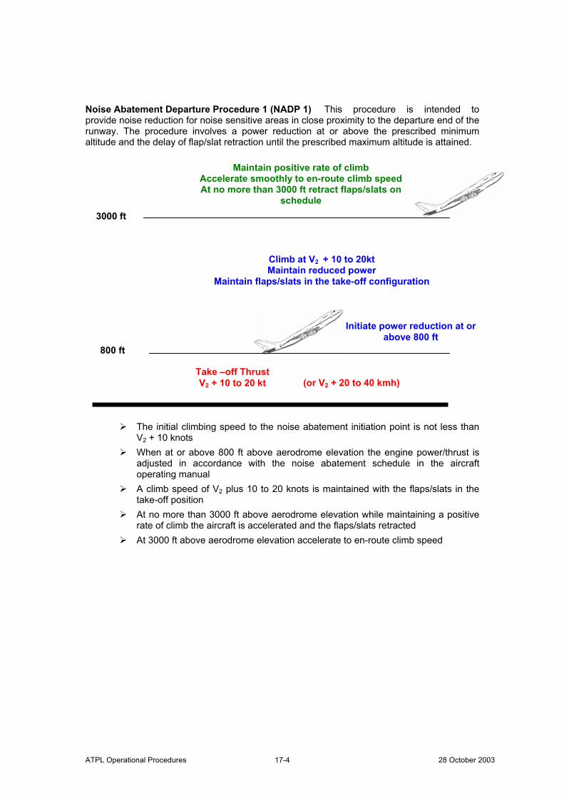
ATPL Operational Procedures 28 October 2003 17-4
Noise Abatement Departure Procedure 1 (NADP 1) This procedure is intended to provide noise reduction for noise sensitive areas in close proximity to the departure end of the runway. The procedure involves a power reduction at or above the prescribed minimum altitude and the delay of flap/slat retraction until the prescribed maximum altitude is attained.
The initial climbing speed to the noise abatement initiation point is not less than
V2 + 10 knots When at or above 800 ft above aerodrome elevation the engine power/thrust is
adjusted in accordance with the noise abatement schedule in the aircraft operating manual
A climb speed of V2 plus 10 to 20 knots is maintained with the flaps/slats in the take-off position
At no more than 3000 ft above aerodrome elevation while maintaining a positive rate of climb the aircraft is accelerated and the flaps/slats retracted
At 3000 ft above aerodrome elevation accelerate to en-route climb speed
800 ft
3000 ft
Take –off Thrust V2 + 10 to 20 kt (or V2 + 20 to 40 kmh)
Initiate power reduction at or above 800 ft
Climb at V2 + 10 to 20kt Maintain reduced power
Maintain flaps/slats in the take-off configuration
Maintain positive rate of climb Accelerate smoothly to en-route climb speed At no more than 3000 ft retract flaps/slats on
schedule
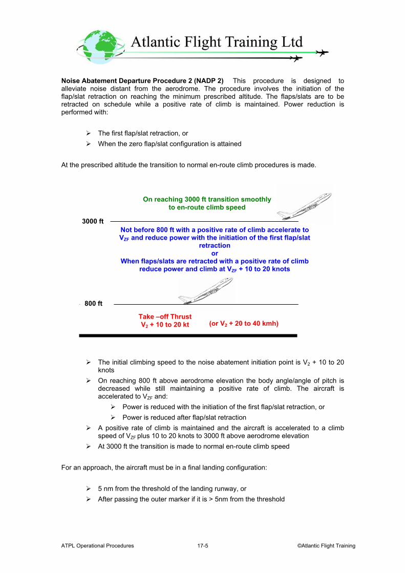
ATPL Operational Procedures ©Atlantic Flight Training 17-5
Noise Abatement Departure Procedure 2 (NADP 2) This procedure is designed to alleviate noise distant from the aerodrome. The procedure involves the initiation of the flap/slat retraction on reaching the minimum prescribed altitude. The flaps/slats are to be retracted on schedule while a positive rate of climb is maintained. Power reduction is performed with:
The first flap/slat retraction, or When the zero flap/slat configuration is attained
At the prescribed altitude the transition to normal en-route climb procedures is made.
The initial climbing speed to the noise abatement initiation point is V2 + 10 to 20 knots
On reaching 800 ft above aerodrome elevation the body angle/angle of pitch is decreased while still maintaining a positive rate of climb. The aircraft is accelerated to VZF and:
Power is reduced with the initiation of the first flap/slat retraction, or Power is reduced after flap/slat retraction
A positive rate of climb is maintained and the aircraft is accelerated to a climb speed of VZF plus 10 to 20 knots to 3000 ft above aerodrome elevation
At 3000 ft the transition is made to normal en-route climb speed
For an approach, the aircraft must be in a final landing configuration:
5 nm from the threshold of the landing runway, or After passing the outer marker if it is > 5nm from the threshold
800 ft
3000 ft
Take –off Thrust V2 + 10 to 20 kt (or V2 + 20 to 40 kmh)
On reaching 3000 ft transition smoothly
to en-route climb speed
Not before 800 ft with a positive rate of climb accelerate to VZF and reduce power with the initiation of the first flap/slat
retraction or
When flaps/slats are retracted with a positive rate of climb reduce power and climb at VZF + 10 to 20 knots
ATPL Operational Procedures 28 October 2003 17-6
For landing there is no limitation on the use of reverse thrust. A displaced threshold is only used for noise abatement if:
Noise is sufficiently reduced The runway distance is still sufficiently long for the operations required
The following conditions preclude the choice of runway to use with regard to noise abatement:
If the runway is not clear and dry The cloud ceiling is 500 ft (150 m) for landing or the horizontal visibility is less
than 1.9 km for take-off or landing The cross wind component including gusts exceeds 15 knots The tail wind component including gusts exceeds 5 kt When windshear has been reported or is forecast When thunderstorms are expected to affect the approach or departure
Fire and Smoke
Carburettor Fire If the engine has not started
Move the mixture control to idle cut off Open the throttle fully Continue to operate the starter motor
If the engine has started Keep the engine going
In both cases, if the fire does not go out action the Engine Fire Drill Engine Fire Account must be taken of whether the aeroplane is in the air or on the ground. The following are general considerations and are not specific to type. Piston Engine Fire
Fuel off Allow the engine to run dry The system should then be purged of fuel Ignition off
Jet Engine Fire
Close the throttle lever Engine start lever to cut off
ATPL Operational Procedures ©Atlantic Flight Training 17-7
Pull the engine fire warning switch
If the warning continues Operate the fire extinguisher system
If this does not work, after 30 seconds
Operate the second fire extinguisher system
Turboprop Engine Fire Same as for the Jet Engine Fire except that at some stage the propeller will need feathering.
AMC OPS 1.790 - Hand Fire Extinguishers The number and location of hand fire extinguishers must be sufficient to provide adequate availability for use, account being taken of the number and size of the passenger compartments, the need to minimise the hazard of toxic gas concentrations and the location of toilets, galleys etc. These considerations may result in the number being greater than the minimum prescribed. There should be at least one fire extinguisher suitable for both flammable fluid and electrical equipment fires installed on the flight deck. Additional extinguishers may be required for the protection of other areas accessible to the crew in flight. Dry chemical fire extinguishers should not be used on the flight deck because of the adverse effect on vision during discharge and, if non-conductive, interference with electrical contacts by the chemical residues. Where only one hand fire extinguisher is required in the passenger compartments it should be located near the cabin crew member's station, where provided. Where two or more hand fire extinguishers are required in the passenger compartments they should be located near each end of the cabin with the remainder distributed throughout the cabin as evenly as is practicable. Unless an extinguisher is clearly visible, a sign should indicate its location. JAR 25.857 Cargo compartment classification a. Class A A Class A cargo or baggage compartment is one in which --
i. The presence of a fire would be easily discovered by a crew member while at his station; and ii. Each part of the compartment is easily accessible in flight.
ATPL Operational Procedures 28 October 2003 17-8
b. Class B A Class B cargo or baggage compartment is one in which:
i. There is sufficient access in flight to enable a crew member to effectively reach any part of the compartment with the contents of a hand fire extinguisher; ii. When the access provisions are being used no hazardous quantity of smoke, flames or extinguishing agent will enter any compartment occupied by the crew or passengers; and iii. There is a separate approved smoke detector or fire detector system to give warning to the pilot or flight engineer station.
c. Class C A Class C cargo or baggage compartment is one not meeting the
requirements for either a Class A or B compartment but in which:
i. There is a separate approved smoke detector or fire detector system to give warning at the pilot or flight engineer station; ii. There is an approved built-in fire-extinguishing system controllable from the pilot or flight engineer stations; iii. There are means to exclude hazardous quantities of smoke, flames, or extinguishing agent, from any compartment occupied by the crew or passengers; and iv. There are means to control ventilation and draughts within the compartment so that the extinguishing agent used can control any fire that may start within the compartment.
d. Class D A Class D cargo or baggage compartment is one in which:
i. A fire occurring in it will be completely confined without endangering the safety of the aeroplane or the occupants; ii. There are means to exclude hazardous quantities of smoke, flames, or other noxious gases, from any compartment occupied by the crew or passengers; iii. Ventilation and draughts are controlled within each compartment so that any fire likely to occur in the compartment will not progress beyond safe limits; iv. Consideration is given to the effect of heat within the compartment on adjacent critical parts of the aeroplane. v. The compartment volume does not exceed 1000 cubic ft.
For compartments of 500 cubic ft or less, an airflow of 1500 cubic ft per hour is acceptable. e. Class E A Class E cargo compartment is one on aeroplanes used only for the
carriage of cargo and in which:
i. There is a separate approved smoke or fire detector system to give warning at the pilot or flight engineer station;
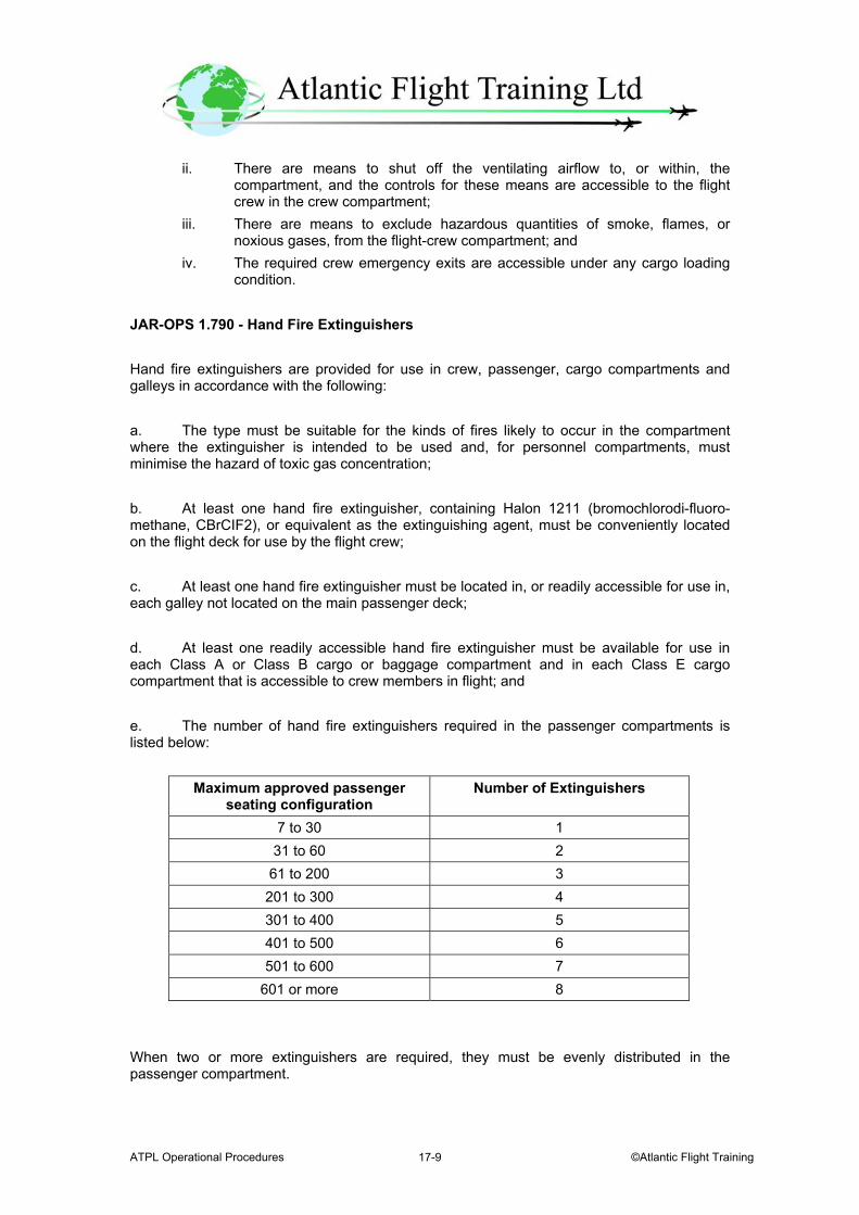
ATPL Operational Procedures ©Atlantic Flight Training 17-9
ii. There are means to shut off the ventilating airflow to, or within, the compartment, and the controls for these means are accessible to the flight crew in the crew compartment; iii. There are means to exclude hazardous quantities of smoke, flames, or noxious gases, from the flight-crew compartment; and iv. The required crew emergency exits are accessible under any cargo loading condition.
JAR-OPS 1.790 - Hand Fire Extinguishers Hand fire extinguishers are provided for use in crew, passenger, cargo compartments and galleys in accordance with the following: a. The type must be suitable for the kinds of fires likely to occur in the compartment where the extinguisher is intended to be used and, for personnel compartments, must minimise the hazard of toxic gas concentration; b. At least one hand fire extinguisher, containing Halon 1211 (bromochlorodi-fluoro-methane, CBrCIF2), or equivalent as the extinguishing agent, must be conveniently located on the flight deck for use by the flight crew; c. At least one hand fire extinguisher must be located in, or readily accessible for use in, each galley not located on the main passenger deck; d. At least one readily accessible hand fire extinguisher must be available for use in each Class A or Class B cargo or baggage compartment and in each Class E cargo compartment that is accessible to crew members in flight; and e. The number of hand fire extinguishers required in the passenger compartments is listed below:
Maximum approved passenger seating configuration
Number of Extinguishers
7 to 30 1 31 to 60 2
61 to 200 3 201 to 300 4 301 to 400 5 401 to 500 6 501 to 600 7
601 or more 8 When two or more extinguishers are required, they must be evenly distributed in the passenger compartment.

ATPL Operational Procedures 28 October 2003 17-10
f. At least one of the required fire extinguishers located in the passenger compartment of an aeroplane with a maximum approved passenger seating configuration of at least 31, and not more than 60, and at least two of the fire extinguishers located in the passenger compartment of an aeroplane with a maximum approved passenger seating configuration of 61 or more must contain Halon 1211 (bromochlorodi-fluoromethane, CBrCIF2), or equivalent as the extinguishing agent. The hand fire extinguishers that may be used in an aircraft are:
Extinguisher Colour Use Remarks Halon 1211 – BCF Green General Anywhere on aircraft
Water Red Domestic fires Nil CO2 Black Electrical fires Not on flight deck
Dry Powder Blue Electrical and liquid fires
Not on flight deck
Automatically triggered water or CO2 extinguishers generally protect toilets. Class of Fires The following classes of fire need to be known:
Class A Solids, ordinary combustible material Class B Flammable liquids Class C Gases Class D Combustible metals
Fire Detection Fire detection systems to be found on an aircraft include:
Electro optical systems which work by the interruption of a beam of light Heat detection systems
Brake Overheat When overheated brakes occur there is a danger that the tyres and brakes may explode. Fire crews should be in attendance while the brakes are in an overheated state. This can take a substantial time. If the aircraft has to be approached it should be from the front or rear and not from the side.
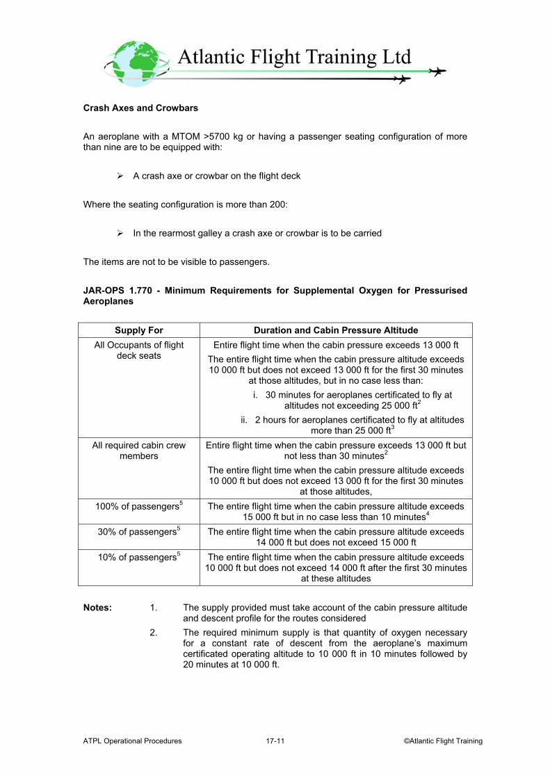
ATPL Operational Procedures ©Atlantic Flight Training 17-11
Crash Axes and Crowbars An aeroplane with a MTOM >5700 kg or having a passenger seating configuration of more than nine are to be equipped with:
A crash axe or crowbar on the flight deck Where the seating configuration is more than 200:
In the rearmost galley a crash axe or crowbar is to be carried The items are not to be visible to passengers. JAR-OPS 1.770 - Minimum Requirements for Supplemental Oxygen for Pressurised Aeroplanes
Supply For Duration and Cabin Pressure Altitude All Occupants of flight
deck seats Entire flight time when the cabin pressure exceeds 13 000 ft
The entire flight time when the cabin pressure altitude exceeds 10 000 ft but does not exceed 13 000 ft for the first 30 minutes
at those altitudes, but in no case less than: i. 30 minutes for aeroplanes certificated to fly at
altitudes not exceeding 25 000 ft2 ii. 2 hours for aeroplanes certificated to fly at altitudes
more than 25 000 ft3
All required cabin crew members
Entire flight time when the cabin pressure exceeds 13 000 ft but not less than 30 minutes2
The entire flight time when the cabin pressure altitude exceeds 10 000 ft but does not exceed 13 000 ft for the first 30 minutes
at those altitudes, 100% of passengers5 The entire flight time when the cabin pressure altitude exceeds
15 000 ft but in no case less than 10 minutes4
30% of passengers5 The entire flight time when the cabin pressure altitude exceeds 14 000 ft but does not exceed 15 000 ft
10% of passengers5 The entire flight time when the cabin pressure altitude exceeds 10 000 ft but does not exceed 14 000 ft after the first 30 minutes
at these altitudes Notes: 1. The supply provided must take account of the cabin pressure altitude and descent profile for the routes considered
2. The required minimum supply is that quantity of oxygen necessary for a constant rate of descent from the aeroplane’s maximum certificated operating altitude to 10 000 ft in 10 minutes followed by 20 minutes at 10 000 ft.
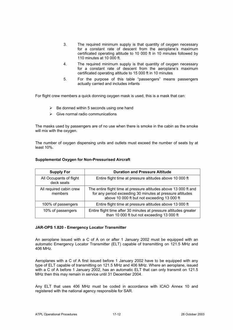
ATPL Operational Procedures 28 October 2003 17-12
3. The required minimum supply is that quantity of oxygen necessary for a constant rate of descent from the aeroplane’s maximum certificated operating altitude to 10 000 ft in 10 minutes followed by 110 minutes at 10 000 ft.
4. The required minimum supply is that quantity of oxygen necessary for a constant rate of descent from the aeroplane’s maximum certificated operating altitude to 15 000 ft in 10 minutes
5. For the purpose of this table “passengers” means passengers actually carried and includes infants
For flight crew members a quick donning oxygen mask is used, this is a mask that can:
Be donned within 5 seconds using one hand Give normal radio communications
The masks used by passengers are of no use when there is smoke in the cabin as the smoke will mix with the oxygen. The number of oxygen dispensing units and outlets must exceed the number of seats by at least 10%. Supplemental Oxygen for Non-Pressurised Aircraft
Supply For Duration and Pressure Altitude All Occupants of flight
deck seats Entire flight time at pressure altitudes above 10 000 ft
All required cabin crew members
The entire flight time at pressure altitudes above 13 000 ft and for any period exceeding 30 minutes at pressure altitudes
above 10 000 ft but not exceeding 13 000 ft 100% of passengers Entire flight time at pressure altitudes above 13 000 ft 10% of passengers Entire flight time after 30 minutes at pressure altitudes greater
than 10 000 ft but not exceeding 13 000 ft JAR-OPS 1.820 - Emergency Locator Transmitter An aeroplane issued with a C of A on or after 1 January 2002 must be equipped with an automatic Emergency Locator Transmitter (ELT) capable of transmitting on 121.5 MHz and 406 MHz. Aeroplanes with a C of A first issued before 1 January 2002 have to be equipped with any type of ELT capable of transmitting on 121.5 MHz and 406 MHz. Where an aeroplane, issued with a C of A before 1 January 2002, has an automatic ELT that can only transmit on 121.5 MHz then this may remain in service until 31 December 2004. Any ELT that uses 406 MHz must be coded in accordance with ICAO Annex 10 and registered with the national agency responsible for SAR.
ATPL Operational Procedures ©Atlantic Flight Training 17-13
JAR-OPS 1.825 - Life Jackets A land aeroplane should not be operated when:
Flying over water and at a distance of more than 50 nm from the shore, or When taking off or landing when the approach path is such that in the event of an
emergency there is a likelihood of ditching Unless it is equipped with Life Jackets equipped with a survivor light for each person on board. Each life jacket must be stored in an easily accessible place. JAR-OPS 1.830 - Life Rafts and Survival ELTs for Extended Overwater Flights Overwater flights are not to be operated at a distance away from land which is suitable for making an emergency landing greater to that corresponding to:
120 minutes at cruising speed or 400 nm whichever is the lesser for aeroplanes capable of continuing the flight to an aerodrome with the critical power unit inoperative at any point along the route or planned diversions, or
30 minutes at cruising speed or 100 nm whichever is the lesser for all other aeroplanes.
For the above to apply the following equipment must be carried:
Sufficient life rafts to carry all persons on board. The life rafts have to be equipped with:
A survival locator light Life saving equipment
Two ELTs
JAR-OPS 1.835 - Survival Equipment An aircraft should not be operated over terrain where SAR would be difficult unless it is equipped with:
Pyrotechnic signalling devices One ELT Additional survival equipment taking into account the number of persons on
board. This equipment need not be carried when the aeroplane:
ATPL Operational Procedures 28 October 2003 17-14
Remains within a distance from an area where SAR is not difficult corresponding to:
120 minutes at the one engine inoperative cruising speed for aeroplanes capable of continuing flight when the critical power unit(s) become inoperative at any point along the flight, or
30 minutes at cruising speed for all other aeroplanes
For JAR 25 aeroplanes the distance must be no greater than 90 minutes at cruising speed from an area suitable for making an emergency landing
JAR-OPS 1.1235 - Security Requirements An operator shall ensure that all appropriate personnel are familiar, and comply with the relevant requirements of the national security programmes of the State of the operator. JAR-OPS 1.1240 - Training Programmes An operator shall establish, maintain and conduct approved training programmes which enable the operator's personnel to take appropriate action to prevent acts of unlawful interference such as sabotage or unlawful seizure of aeroplanes and to minimise the consequences of such events should they occur. JAR-OPS 1.1245 - Reporting Acts of Unlawful Interference Following an act of unlawful interference on board an aeroplane the commander or, in his absence the operator, shall submit, without delay, a report of such an act to the designated local authority and the Authority in the State of the operator. JAR-OPS 1.1250 - Aeroplane Search Procedure Checklist An operator shall ensure that all aeroplanes carry a checklist of the procedures to be followed for that type in searching for concealed weapons, explosives, or other dangerous devices. JAR-OPS 1.1255 - Flight Crew Compartment Security If installed, the flight crew compartment door on all aeroplanes operated for the purpose of carrying passengers shall be capable of being locked from within the compartment in order to prevent unauthorised access. JAR 25.1001 Fuel jettisoning system a. A fuel jettisoning system must be installed on each aeroplane unless it is shown that the aeroplane meets the climb requirements of JAR 25.119 and 25.121(d) at maximum take-off weight, less the actual or computed weight of fuel necessary for a 15-minute flight comprised of a take-off, go-around, and landing at the airport of departure with the aeroplane
ATPL Operational Procedures ©Atlantic Flight Training 17-15
configuration, speed, power, and thrust the same as that used in meeting the applicable take-off approach, and landing climb performance requirements of this JAR-25. b. If a fuel jettisoning system is required it must be capable of jettisoning enough fuel within 15 minutes, starting with the weight given in sub-paragraph (a) of this paragraph, to enable the aeroplane to meet the climb requirements of JAR 25.119 and 25.121(d), assuming that the fuel is jettisoned under the conditions, except weight, found least favourable during the flight tests prescribed in sub-paragraph (c) of this paragraph. c. Fuel jettisoning must be demonstrated beginning at maximum take-off weight with wing-flaps and landing gear up and in:
i. A power-off glide at 1.4 VS1; ii. A climb at the one-engine inoperative best rate-of-climb speed, with the critical engine inoperative and the remaining engines at maximum continuous power; and iii. Level flight at 1.4 VS1, if the results of the tests in the condition specified in sub-paragraph (c)(1) and (2) of this paragraph show that this condition could be critical.
d. During the flight tests prescribed in sub-paragraph (c) of this paragraph, it must be shown that:
i. The fuel jettisoning system and its operation are free from fire hazard; ii. The fuel discharges clear of any part of the aeroplane; iii. Fuel or fumes do not enter any part of the aeroplane; iv The jettisoning operation does not adversely affect the controllability of the aeroplane.
e. Means must be provided to prevent jettisoning the fuel in the tanks used for take-off and landing below the level allowing climb from sea level to 10 000 ft and thereafter allowing 45 minutes cruise at a speed for maximum range. However, if there is an auxiliary control independent of the main jettisoning control, the system may be designed to jettison the remaining fuel by means of the auxiliary jettisoning control.
Fuel should not be jettisoned below 10 000 ft In winter in exceptional circumstances this can be lowered to 7000 ft In summer in exceptional circumstances this can be lowered to 4000 ft
f. The fuel jettisoning valve must be designed to allow flight personnel to close the valve during any part of the jettisoning operation. g. Unless it is shown that using any means (including flaps, slots and slats) for changing the airflow across or around the wings does not adversely affect fuel jettisoning, there must be a placard, adjacent to the jettisoning control, to warn flight-crew members against jettisoning fuel while the means that change the airflow are being used.
ATPL Operational Procedures 28 October 2003 17-16
h. The fuel jettisoning system must be designed so that any reasonably probable single malfunction in the system will not result in a hazardous condition due to unsymmetrical jettisoning of, or inability to jettison, fuel. Transport of Dangerous Goods by Air JAR-OPS 1.1150 - Terminology a. Terms used in this Subpart have the following meanings:
Acceptance Check List A document used to assist in carrying out a check on the external appearance of packages of dangerous goods and their associated documents to determine that all appropriate requirements have been met. Cargo Aircraft Any aircraft which is carrying goods or property but not passengers. In this context the following are not considered to be passengers:
i. A crew member; ii. An operator's employee permitted by, and carried in accordance with, the instructions contained in the Operations Manual; iii. An authorised representative of an Authority; or iv A person with duties in respect of a particular shipment on board.
Dangerous Goods Accident An occurrence associated with and related to the
transport of dangerous goods which results in fatal or serious injury to a person or major property damage.
Dangerous Goods Incident An occurrence, other than a dangerous goods accident, associated with and related to the transport of dangerous goods, not necessarily occurring on board an aircraft, which results in injury to a person, property damage, fire, breakage, spillage, leakage of fluid or radiation or other evidence that the integrity of the packaging has not been maintained. Any occurrence relating to the transport of dangerous goods which seriously jeopardises the aircraft or its occupants is also deemed to constitute a dangerous goods incident.
Dangerous Goods Transport Document A document which is specified by the Technical Instructions. It is completed by the person who offers dangerous goods for air transport and contains information about those dangerous goods. The document bears a signed declaration indicating that the dangerous goods are fully and accurately described by their proper shipping names and UN numbers (if assigned) and that they are correctly classified, packed, marked, labelled and in a proper condition for transport. Freight Container A freight container is an article of transport equipment for radioactive materials, designed to facilitate the transport of such materials, either packaged or unpackaged, by one or more modes of transport.
ATPL Operational Procedures ©Atlantic Flight Training 17-17
Handling Agent An agency which performs on behalf of the operator some or all of the latter's functions including receiving, loading, unloading, transferring or other processing of passengers or cargo.
Overpack An enclosure used by a single shipper to contain one or more packages and to form one handling unit for convenience of handling and stowage. Package The complete product of the packing operation consisting of the packaging and its contents prepared for transport. Packaging Receptacles and any other components or materials necessary for the receptacle to perform its containment function and to ensure compliance with the packing requirements. Proper Shipping Name The name to be used to describe a particular article or substance in all shipping documents and notifications and, where appropriate, on packaging. Serious Injury An injury which is sustained by a person in an accident and which:
i Requires hospitalization for more than 48 hours, commencing within seven days from the date the injury was received; or ii Results in a fracture of any bone (except simple fractures of fingers, toes or nose); or iii Involves lacerations which cause severe haemorrhage, nerve, muscle or tendon damage; or iv Involves injury to any internal organ; or v Involves second or third degree burns, or any burns affecting more than 5% of the body surface; or vi Involves verified exposure to infectious substances or injurious radiation.
State of Origin The Authority in whose territory the dangerous goods were first loaded on an aircraft. Technical Instructions The latest effective edition of the Technical Instructions for the Safe Transport of Dangerous Goods by Air (Doc 9284-AN/905), including the Supplement and any Addendum, approved and published by decision of the Council of the International Civil Aviation Organization. UN Number The four-digit number assigned by the United Nations Committee of Experts on the Transport of Dangerous Goods to identify a substance or a particular group of substances.
ATPL Operational Procedures 28 October 2003 17-18
Unit Load Device Any type of aircraft container, aircraft pallet with a net, or aircraft pallet with a net over an igloo. (Note: an overpack is not included in this definition; for a container containing radioactive materials see the definition for freight container.)
Dangerous Goods Categories
Class 1 - Explosives Class 2 - Compressed gases Class 3 - Flammable liquids Class 4 - Other flammable hazards Class 5 - Oxygen rich material, oxidizers and organic peroxides Class 6 - Material affecting health, poisons and infectious substances Class 7 - Radioactive material Class 8 - Corrosive material Class 9 - Miscellaneous hazards.
JAR-OPS 1.1160 - Scope a. An operator shall comply with the provisions contained in the Technical Instructions on all occasions when dangerous goods are carried, irrespective of whether the flight is wholly or partly within or wholly outside the territory of a State. b. Articles and substances which would otherwise be classed as dangerous goods are excluded from the provisions of this Subpart, to the extent specified in the Technical Instructions, provided:
i. They are required to be aboard the aeroplane in accordance with the relevant JARs or for operating reasons; ii. They are carried as catering or cabin service supplies; iii. They are carried for use in flight as veterinary aid or as a humane killer for an
animal iv. They are carried for use in flight for medical aid for a patient, provided that:
(a) Gas cylinders have been manufactured specifically for the purpose of containing and transporting that particular gas; (b) Drugs, medicines and other medical matter are under the control of trained personnel during the time when they are in use in the aeroplane; (c) Equipment containing wet cell batteries is kept and, when necessary secured, in an upright position to prevent spillage of the electrolyte; and (d) Proper provision is made to stow and secure all the equipment during take-off and landing and at all other times when deemed necessary by the commander in the interest of safety; or
ATPL Operational Procedures ©Atlantic Flight Training 17-19
v. They are carried by passengers or crew members.
Articles and substances intended as replacements for those in (b.i) above shall be transported on an aeroplane as specified in the Technical Instructions. JAR-OPS 1.1170 - Classification An operator shall take all reasonable measures to ensure that articles and substances are classified as dangerous goods as specified in the Technical Instructions. IEM OPS 1.1160(b)(1) - Dangerous Goods on an Aeroplane in Accordance with the Relevant Regulations or for Operating Reasons Dangerous goods required to be on board an aeroplane in accordance with the relevant JARs or for operating reasons are those which are for:
a. The airworthiness of the aeroplane; b. The safe operation of the aeroplane; or c. The health of passengers or crew.
Such dangerous goods include but are not limited to:
a. Batteries; b. Fire extinguishers; c. First-aid kits; d. Insecticides/Air fresheners; e. Life saving appliances; and f. Portable oxygen supplies.
JAR-OPS 1.1165 - Limitations on the Transport of Dangerous Goods a. An operator shall take all reasonable measures to ensure that articles and substances that are specifically identified by name or generic description in the Technical Instructions as being forbidden for transport under any circumstances are not carried on any aeroplane. b. An operator shall take all reasonable measures to ensure that articles and substances or other goods that are identified in the Technical Instructions as being forbidden for transport in normal circumstances are only transported when:
i. They are exempted by the States concerned under the provisions of the Technical Instructions; or ii. The Technical Instructions indicate they may be transported under an approval issued by the State of Origin.
ATPL Operational Procedures 28 October 2003 17-20
JAR-OPS 1.1175 - Packing An operator shall take all reasonable measures to ensure that dangerous goods are packed as specified in the Technical Instructions. JAR-OPS 1.1185 - Dangerous Goods Transport Document a. An operator shall ensure that, except when otherwise specified in the Technical Instructions, dangerous goods are accompanied by a dangerous goods transport document. b. Where dangerous goods are carried on a flight which takes place wholly or partly outside the territory of a State, the English language must be used for the dangerous goods transport document in addition to any other language requirements. JAR-OPS 1.1200 - Inspection for Damage, Leakage or Contamination a. An operator shall ensure that:
i. Packages, overpacks and freight containers are inspected for evidence of leakage or damage immediately prior to loading on an aeroplane or into a unit load device, as specified in the Technical Instructions; ii. A unit load device is not loaded on an aeroplane unless it has been inspected as required by the Technical Instructions and found free from any evidence of leakage from, or damage to, the dangerous goods contained therein; iii. Leaking or damaged packages, overpacks or freight containers are not loaded on an aeroplane; iv. Any package of dangerous goods found on an aeroplane and which appears to be damaged or leaking is removed or arrangements made for its removal by an appropriate authority or organisation. In this case the remainder of the consignment shall be inspected to ensure it is in a proper condition for transport and that no damage or contamination has occurred to the aeroplane or its load; and v. Packages, overpacks and freight containers are inspected for signs of damage or leakage upon unloading from an aeroplane or from a unit load device and, if there is evidence of damage of leakage, the area where the dangerous goods were stowed is inspected for damage of contamination.
JAR-OPS 1.1210 - Loading Restrictions
Passenger Cabin and Flight Deck An operator shall ensure that dangerous goods are not carried in an aeroplane cabin occupied by passengers or on the flight deck, unless otherwise specified in the Technical Instructions. Cargo Compartments An operator shall ensure that dangerous goods are loaded, segregated, stowed and secured on an aeroplane as specified in the Technical Instructions.
ATPL Operational Procedures ©Atlantic Flight Training 17-21
Dangerous Goods Designated for Carriage Only on Cargo Aircraft An operator shall ensure that packages of dangerous goods bearing the `Cargo Aircraft Only' label are carried on a cargo aircraft and loaded as specified in the Technical Instructions.
JAR-OPS 1.1215 - Provision of Information a. Information to Ground Staff. An operator shall ensure that:
i. Information is provided to enable ground staff to carry out their duties with regard to the transport of dangerous goods, including the actions to be taken in the event of incidents and accidents involving dangerous goods; and ii. Where applicable, the information referred to in sub-paragraph (a.i) above is also provided to his handling agent.
b. Information of Passengers and Other Persons:
i. An operator shall ensure that information is promulgated as required by the Technical Instructions so that passengers are warned as to the types of goods which they are forbidden from transporting aboard an aeroplane; and ii. An operator and, where applicable, his handling agent shall ensure that notices are provided at acceptance points for cargo giving information about the transport of dangerous goods.
c. Information to Crew Members. An operator shall ensure that information is provided in the Operations Manual to enable crew members to carry out their responsibilities in regard to the transport of dangerous goods, including the actions to be taken in the event of emergencies arising involving dangerous goods. d. Information to the Commander. An operator shall ensure that the commander is provided with written information, as specified in the Technical Instructions. e. Information in the Event of an Aeroplane Incident or Accident
i. The operator of an aeroplane which is involved in an aeroplane incident shall, on request, provide any information required to minimise the hazards created by any dangerous goods carried. ii. The operator of an aeroplane which is involved in an aeroplane accident shall, as soon as possible, inform the appropriate authority of the State in which the aeroplane accident occurred of any dangerous goods carried.
ATPL Operational Procedures 28 October 2003 17-22
JAR-OPS 1.1220 - Training Programmes a. An operator shall establish and maintain staff training programmes, as required by the Technical Instructions, which must be approved by the Authority. b. Operators not holding a permanent approval to carry dangerous goods. An operator shall ensure that:
i. Staff who are engaged in general cargo handling have received training to carry out their duties in respect of dangerous goods, and. ii. The following personnel:
(a) Crew members; (b) Passenger handling staff; and (c) Security staff employed by the operator who deal with the screening
of passengers and their baggage, have received training which, as a minimum, must cover to a depth sufficient to ensure that an awareness is gained of the hazards associated with dangerous goods, how to identify them and what requirements apply to the carriage of such goods by passengers. Contaminated runway JAR-OPS 1.480 - Terminology a. Terms used in Subparts F, G, H, I and J, and not defined in JAR-1, have the following meaning:
Accelerate-stop distance available (ASDA) The length of the take-off run available plus the length of stopway, if such stopway is declared available by the appropriate Authority and is capable of bearing the mass of the aeroplane under the prevailing operating conditions. Contaminated runway A runway is considered to be contaminated when more than 25% of the runway surface area (whether in isolated areas or not) within the required length and width being used is covered by the following:
i. Surface water more than 3 mm (0·125 in) deep, or by slush, or loose snow, equivalent to more than 3 mm (0·125 in) of water; ii. Snow which has been compressed into a solid mass which resists further compression and will hold together or break into lumps if picked up (compacted snow); or iii. Ice, including wet ice.
ATPL Operational Procedures ©Atlantic Flight Training 17-23
Contaminant Depth If the following limits are exceeded then a take-off should not be attempted:
i. Dry snow > 60 mm ii. Very dry snow > 80 mm iii. Water, slush or wet snow > 15 mm
Damp runway A runway is considered damp when the surface is not dry, but when the moisture on it does not give it a shiny appearance. Dry runway A dry runway is one which is neither wet nor contaminated, and includes those paved runways which have been specially prepared with grooves or porous pavement and maintained to retain 'effectively dry' braking action even when moisture is present. Landing distance available (LDA) The length of the runway which is declared available by the appropriate Authority and suitable for the ground run of an aeroplane landing. Maximum approved passenger seating configuration The maximum passenger seating capacity of an individual aeroplane, excluding pilot seats or flight deck seats and cabin crew seats as applicable, used by the operator, approved by the Authority and specified in the Operations Manual. Take-off distance available (TODA) The length of the take-off run available plus the length of the clearway available. Take-off mass The take-off mass of the aeroplane shall be taken to be its mass, including everything and everyone carried at the commencement of the take-off run. Take-off run available (TORA) The length of runway which is declared available by the appropriate Authority and suitable for the ground run of an aeroplane taking off. Wet runway A runway is considered wet when the runway surface is covered with water, or equivalent, less than specified in subparagraph (a)(2) above or when there is sufficient moisture on the runway surface to cause it to appear reflective, but without significant areas of standing water.
b. The terms 'accelerate-stop distance', 'take-off distance', 'take-off run', 'net take-off flight path', 'one engine inoperative en-route net flight path' and 'two engines inoperative en-route net flight path' as relating to the aeroplane have their meanings defined in the airworthiness requirements under which the aeroplane was certificated, or as specified by the Authority if it finds that definition inadequate for showing compliance with the performance operating limitations.
ATPL Operational Procedures 28 October 2003 17-24
ACJ 25.1583(k) - Maximum Depth of Runway Contaminants for Take-off Operations (Acceptable Means of Compliance) Compliance with 25.1583(k) may be shown using either Method 1 or Method 2 a. Method 1 If information on the effect of runway contaminants on the expected take-off performance of the aeroplane is given take-off operation should be limited to the contamination depths for which take-off information is provided. b. Method 2 If information on the effect of runway contaminants on the expected take-off performance of the aeroplane is not provided, take-off operation should be limited to runways where the degree of contamination does not exceed the equivalent of 3 mm (0.125 inch) of water, except in isolated areas not exceeding a total of 25% of the area within the required length and width being used.
Note 1 In establishing the maximum depth of runway contaminants it may be necessary to take account of the maximum depth for which the engine air intakes have been shown to be free of ingesting hazardous quantities of water or other contaminants in accordance with 25.1091(d)(2).
Note 2 Unless performance effects are based on tests in water depths
exceeding 15mm, or on other evidence equivalent in accuracy to the results of direct testing. It will not normally be acceptable to approve take-off operation in depths of contaminants exceeding the equivalent of 15mm of water.
Aquaplaning Aquaplaning will not generally take place at a speed below:
V = 9√P Where: V is the groundspeed (knots) P is the tyre pressure (lb per in2) If the surface is covered by a contaminant other than water P must be divided by the specific gravity of the contaminent. Bird Hazard Reduction The bird strike hazard on, or in the vicinity of, an aerodrome should be assessed through:
The establishment of a national procedure for recording and reporting birdstrikes to aircraft, and
ATPL Operational Procedures ©Atlantic Flight Training 17-25
The collection of information from aircraft operations personnel on the presence of birds on or around the aerodrome.
All bird strikes have to be reported. On aerodromes the use of the following will deter birds congregating in large flocks:
Long grass Bird scaring techniques such as
Pyrotechnics (most effective) Bird distress calls
Rubbish tips or other equivalent waste areas will attract birds. A bird will generally react to the proximity of an aircraft within 3 seconds. Security Annex 2 Any aircraft that is being subjected to unlawful interference shall endeavour to:
Notify the appropriate ATS unit of this fact Inform the ATS of any significant circumstances Notify any deviation from the current flight plan necessitated by the above
This is to ensure that the ATS unit gives priority to the aircraft and minimizes any risk of conflict with other aircraft. The following procedures are intended as guidance for use by aircraft when unlawful interference occurs and the aircraft is unable to notify an ATS unit of this fact. Procedures If the Aircraft Is Unable To Notify An ATS Unit Unless considerations on board dictate otherwise:
The PlC should attempt to continue flying on the assigned track and at the assigned cruising level, until
An ATS can be notified, or, the aircraft is within radar coverage Where the aircraft must depart from its assigned track or level without being able to make radio contact with ATS, the PlC should, whenever possible:
ATPL Operational Procedures 28 October 2003 17-26
Attempt to broadcast warnings on the VHF emergency frequency and any other
appropriate frequencies, unless circumstances dictate otherwise Other equipment such as on board transponders, data links etc should also be
used, conditions permitting Proceed in accordance with the applicable special procedures for in-flight
contingencies, where such procedures have been established and promulgated If there is no applicable regional procedure, proceed at a level which differs from
the cruising levels normally used for IFR flight:
300 m (1000 ft) if above FL 290, or 150 m (500 ft) if below FL 290
Annex 6 In all aeroplanes the flight crew compartment door should be capable of being locked from within the compartment Aeroplane Search Procedure Checklist An operator shall ensure that there is on board a checklist of the procedures to be followed in searching for a bomb in case of suspected sabotage. The checklist shall be supported by guidance on the course of action to be taken should a bomb or suspicious object be found, Training Programme An operator shall establish and maintain a training programme that enables crew members to act in the most appropriate manner to minimize the consequences of acts of unlawful interference. An operator shall also establish and maintain a training programme to acquaint appropriate employees with preventative measures and techniques in relation to:
Passengers Baggage Cargo Mail Equipment Stores Supplies intended for carriage on an aeroplane
so that they contribute to the prevention of acts of sabotage or other forms of unlawful interference.
ATPL Operational Procedures ©Atlantic Flight Training 17-27
Annex 14 - Isolated Aircraft Parking Position An isolated aircraft parking position shall be designated or the aerodrome control tower shall be advised of an area or areas suitable for the parking of an aircraft which is known or believed to be the subject of unlawful interference, or which for other reasons needs isolation from normal aerodrome activities. The isolated aircraft parking position should be located at the maximum distance practicable and in any case never less than 100 m from other parking positions, buildings or public areas. Care should be taken to ensure that the position is not located over underground utilities such as gas and aviation fuel and, to the extent feasible, electrical or communication cables Document 4444 - Control of Taxiing Aircraft An aircraft known or believed to be the subject of unlawful interference or which for other reasons needs isolation from normal aerodrome activities shall be cleared to the designated isolated parking position. Where such an isolated parking position has not been designated, or if the designated position is not available, the aircraft shall be cleared to:
A position within the area or areas selected by prior agreement with the aerodrome authority
The taxi clearance shall specify the taxi route to be followed to the parking position
The route shall be selected with a view to minimizing any security risks to the public, other aircraft and installations at the aerodrome Reports A Contracting State in which an aircraft subjected to an act of unlawful interference has landed shall notify by the quickest means the State of Registry of the aircraft and the State of the operator of the landing. Other relevant information shall be transmitted to:
The State of Registry and the State of the operator Each state whose citizens suffered fatalities or injuries Each state whose citizens were detained as hostages Each Contracting State whose citizens are known to be on board the aircraft The ICAO
Measures Related To Passengers And Their Cabin Baggage Each Contracting State shall ensure that adequate measures are taken to control transfer and transit passengers and their cabin baggage to prevent unauthorized articles from being taken on board aircraft engaged in international civil aviation operations.
ATPL Operational Procedures 28 October 2003 17-28
Each Contracting State shall ensure that there is no possibility of mixing or contact between passengers subjected to security control and other persons not subjected to such control after the security screening at airports have been passed. If mixing or contact does take place, the passengers concerned and their cabin baggage shall be re-screened before boarding an aircraft. General Objectives of the Measures Each Contracting State shall establish measures to prevent weapons, explosives or any other dangerous devices which may be used to commit an act of unlawful interference, the carriage or bearing of which is not authorized, from being introduced, by any means whatsoever, on board an aircraft engaged in international civil aviation. JAR-OPS 1.420 - Occurrence Reporting Definitions
Incident An occurrence, other than an accident, associated with the operation of an aircraft which affects or could affect the safety of operation Serious Incident An incident involving circumstances indicating that an accident nearly occurred Accident An occurrence associated with the operation of an aircraft which takes place between the time any person boards the aircraft with the intention of flight until such time as all persons have disembarked in which:
A person is fatally or seriously injured as a result of:
Being in the aircraft Being in direct contact with any part of the aircraft, including parts
which have become detached from the aircraft, or Direct exposure to jet blast
Except when the injuries are from:
Natural causes Self inflicted Inflicted by other persons, or When the injuries are to stowaways hiding outside the areas normally
available to the passengers and crew
The aircraft sustains damage or structural failure which adversely affects:
The structural strength
ATPL Operational Procedures ©Atlantic Flight Training 17-29
Performance or flight characteristics
which would normally require major repair or replacement of the affected component. This excludes:
Engine failure or damage when the damage is limited to the:
Engine Engine cowlings Engine accessories
Propellers Wing tips Antennae Tyres Brakes Fairings Small dents Small puncture holes in the skin
The aircraft is missing or completely inaccessible.
Incident Reporting The operator establishes procedures for reporting incidents taking into account the following:
The responsibilities of crewmembers for reporting incidents that endanger, or could endanger, the safety of the operation
The commander shall submit a report to the authority of any incident that endangers, or could endanger, the safety of the operation
Reports have to be dispatched within 72 hours of the time of the incident unless circumstances prevent
The commander ensures that all known or suspected defects and exceedances of the technical limitations are recorded in the technical log. If these endanger or could endanger the safety of the operation then an incident report must be submitted
Accident and Serious Incident Reporting The operator establishes procedures for reporting accidents and serious incidents taking into account the following:
ATPL Operational Procedures 28 October 2003 17-30
The commander shall notify the operator of any accident and serious incident. Where the commander is unable to do this then the reporting has to be done by any other member of the crew.
The operator shall ensure that the Authority in the State of the Operator and any other organisations specified by the State of the Operator are informed of an accident or serious incident by the quickest means. For an accident this is before the aeroplane is moved.
The commander shall submit a report within 72 hours ACAS Resolution Advisory The commander notifies the ATSU concerned and submits an ACAS report to the authority when an aircraft has manoeuvred in response to a Resolution Advisory. Bird Hazards and Strikes When a potential bird hazard is observed the commander will immediately inform the local ATSU. Where a bird strike has occurred then a written bird strike report is submitted to the authority after landing if the aircraft has sustained significant damage. If the commander is unable to do this then the operator must submit the report. In-flight Emergencies with Dangerous Goods on Board Where an emergency occurs and if the situation permits the appropriate ATSU is informed of dangerous goods that are on board an aircraft. After landing, if the occurrence has been related to the transport of dangerous goods then the commander must comply with the reporting procedures applicable to dangerous goods. Unlawful Interference Following an act of unlawful interference the commander shall submit a report to the authority as soon as is practicable. Encountering Potential Hazardous Conditions The commander shall notify the appropriate ATSU as soon as is practicable when a potentially hazardous condition exists. This can include:
Irregularities in ground or navigational facilities Meteorological phenomena Volcanic ash cloud that is encountered in flight
ATPL Operational Procedures ©Atlantic Flight Training 17-31
JAR-OPS 1.1250 - Aeroplane Search Procedure Checklist The operator ensures that all aeroplanes carry a checklist of the procedures to be followed for searching for:
Concealed weapons Explosives Other dangerous devices
The checklist should also give guidance on the action to be taken if a bomb or suspicious object is found.

ATPL Operational Procedures 28 October 2003 17-32
Intentionally Left Blank
ATPL Operational Procedures ©Atlantic Flight Training 18-1
PART 3. NORTH ATLANTIC (NAT) MINIMUM NAVIGATION PERFORMANCE SPECIFICATION (MNPS) AIRSPACE
Chapter 18.
Operational Approval and Aircraft System Requirements for Flight in the NAT MNPS Airspace
The following chapters are all abridged from the North Atlantic MNPS Airspace Operations Manual – Ninth Edition Introduction All material relating to North Atlantic aircraft operations can be found in the following documents:
ICAO Annexes PANS/RAC (Doc.4444) Regional Supplementary Procedures (Doc.7030) State AIPs, and Current NOTAMs
These documents are complementary to the North Atlantic MNPS Airspace Operations Manual – Ninth Edition. The following chapters have been produced principally for the Operational Procedures Examination of the JAR ATPL. Some material may be useful in the Aviation Law Examination. The subjects discussed include:
The vertical extent of the airspace in which Reduced Vertical Separation Minimum (RVSM) may be employed
Information relating to the use of GNSS Flight Planning Procedures Oceanic Clearance Procedures The use of Data Link Air/Ground Communications within MNPS Airspace North Atlantic and Europe Regional Supplementary Procedures
Minimum Navigation Performance Specification Airspace The vertical dimension of MNPS Airspace is between FL285 and FL420; the cruising levels available are FL290 to FL410 inclusive.
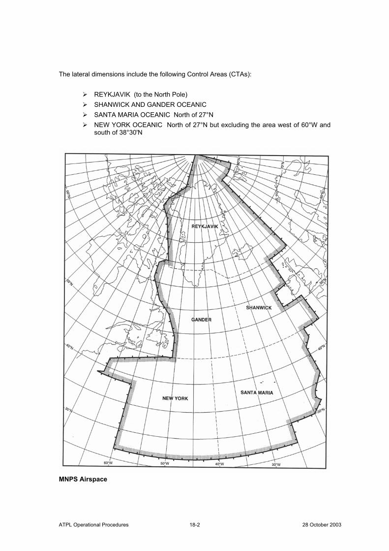
ATPL Operational Procedures 28 October 2003 18-2
The lateral dimensions include the following Control Areas (CTAs):
REYKJAVIK (to the North Pole) SHANWICK AND GANDER OCEANIC SANTA MARIA OCEANIC North of 27°N NEW YORK OCEANIC North of 27°N but excluding the area west of 60°W and
south of 38°30'N
MNPS Airspace
ATPL Operational Procedures ©Atlantic Flight Training 18-3
No aircraft can fly across the North Atlantic within MNPS Airspace, or RVSM Airspace, unless the State of Registry or the State of the Operator approves them. RVSM applies from FL310 to FL390 throughout NAT MNPS airspace. Around November 2001 RVSM will apply in the entire NAT Region. When this happens MNPS airspace will become a sub-division of RVSM airspace. The following abbreviations are to be used in conjunction with the following chapters. Abbreviations ACC Area Control Centre ADC Air Data Computer AFTN Aeronautical Fixed Telecommunication Network AIC Aeronautical Information Circular AIP Aeronautical Information Publication AIS Aeronautical Information Service ARINC ARINC - formerly Aeronautical Radio Incorporated ASR Aviation Safety Report ATA Actual Time of Arrival ATM Air Traffic Management AWPR Automatic Waypoint Reporting BRNAV Basic Area Navigation CAR Caribbean CDU Control Display Unit CMA Central Monitoring Agency CTA Control Area DCPC Direct Controller/Pilot Communications DME Distance Measuring Equipment DR Dead Reckoning ELT Emergency Locator Transmitter ETA Estimated Time of Arrival ETOPS Extended Range Twin-engine Aircraft Operations EUR Europe FDE Fault Detection and Exclusion FIR Flight Information Region FL Flight Level FLAS Flight Level Allocation Scheme FMC Flight Management Computer FMS Flight Management System GLONASS Global Orbiting Navigation Satellite System
ATPL Operational Procedures 28 October 2003 18-4
GMU GPS (Height) Monitoring Unit GNE Gross Navigation Error GNSS Global Navigation Satellite System GP General Purpose GPS Global Positioning System HMU Height Monitoring Unit IATA International Air Transport Association ICAO International Civil Aviation Organisation JAA Joint Aviation Authorities LRNS Long Range Navigation System MASPS Minimum Aircraft System Performance Specification MEL Minimum Equipment List MNPS Minimum Navigation Performance Specification MTT Minimum Time Track NAM North America NAR North American Route NAT North Atlantic NAT SPG North Atlantic Systems Planning Group NDB Non Directional Beacon nm Nautical Mile NOAA National Oceanic and Atmospheric Administration OAC Oceanic Area Control Centre OCA Oceanic Control Area OTS Organized Track System PRM Preferred Route Message PTS Polar Track Structure RA Resolution Advisory RAIM Receiver-Autonomous Integrity Monitoring RMI Remote Magnetic Indicator RNP Required Navigation Performance RVSM Reduced Vertical Separation Minimum SELCAL Selective Calling SID Standard Instrument Departure SSB Single Sideband SSR Secondary Surveillance Radar SST Supersonic Transport TA Traffic Advisory TAS True Airspeed TCAS Traffic (Alert and) Collision Avoidance System TLS Target Level of Safety TMI Track Message Identification
ATPL Operational Procedures ©Atlantic Flight Training 18-5
WAH When Able Higher WATRS West Atlantic Route System General All flights in MNPS airspace must achieve the highest standards of horizontal and vertical navigation performance and accuracy. Aircraft operating within MNPS Airspace are required to meet a Minimum Navigation Performance Specification (MNPS) in the horizontal plane through the mandatory carriage and use of a specified level of navigation equipment. Aircraft operating at RVSM levels in NAT MNPS Airspace are required to be equipped with altimetry and height keeping systems which meet RVSM Minimum Aircraft System Performance Specifications (MASPS). The ultimate responsibility for checking that a NAT MNPS/RVSM flight has the necessary approval rests with the pilot in command. For flights over the NAT Emergency Locator Transmitters (ELTs) must be carried. These beacons must operate on frequency 406 MHz and have a 121.5 MHz search and rescue homing capability. Approval Approval for MNPS operations requires that the following is checked by the State of Registry and the State of the Operator:
The navigation equipment used, together with its installation and maintenance procedures;
The crew navigation procedures employed, and The training requirements.
Navigation Requirements for Unrestricted MNPS Airspace Operations Longitudinal Navigation Longitudinal separations between aircraft following the same track and between aircraft on intersecting tracks in the NAT MNPS Airspace are assessed by use of ATAs/ETAs at common waypoints. The longitudinal separation minima currently used in the NAT MNPS Airspace are expressed in clock minutes and the maintenance of in-trail separations is aided by the application of the Mach Number Technique.
ATPL Operational Procedures 28 October 2003 18-6
Aircraft clock errors can result in waypoint ATA reporting errors. The time-keeping device intended to be used to indicate waypoint passing times must be accurate, and synchronised to an acceptable UTC time signal before commencing flight in MNPS Airspace. The pre-flight procedures for any NAT MNPS operation must include a UTC time check and resynchronisation of the aircraft Master Clock. Lateral Navigation There are two navigational requirements for aircraft planning to operate in MNPS Airspace:
The navigation performance which should be achieved, in terms of accuracy. The need to carry standby equipment with comparable performance
characteristics For approval of unrestricted operation in the MNPS Airspace an aircraft must be equipped with the following:
Two fully serviceable Long Range Navigation Systems (LRNSs). A LRNS may
be one of the following: One Inertial Navigation System (INS); One Global Navigation Satellite System (GNSS); or One navigation system using the inputs from one or more Inertial
Reference System (IRS) or any other sensor system complying with the MNPS requirement.
Each LRNS must be capable of providing to the flight crew a continuous indication of the aircraft position relative to desired track. Routes for Use by Aircraft Not Equipped With Two LRNSs Routes for Aircraft with Only One LRNS A number of special routes have been developed for aircraft equipped with only one LRNS and carrying normal short-range navigation equipment (VOR, DME, ADF). These routes are:
Within MNPS Airspace, and that State approval must be obtained prior to flying along them.
Also available for interim use by aircraft normally approved for unrestricted MNPS operations that have suffered a partial loss of navigation capability and have only a single remaining functional LRNS.
Detailed descriptions of the special routes known as “Blue Spruce Routes” are included later.
ATPL Operational Procedures ©Atlantic Flight Training 18-7
Routes for Aircraft with Short-Range Navigation Equipment Only Aircraft which are equipped only with short-range navigation equipment (VOR, DME, ADF) may operate through MNPS Airspace, along routes G3 or G11, but State approval is required. It is the responsibility of pilots with limited certification to reject clearances that would otherwise divert them from officially permitted routes. Special Arrangements For The Penetration Of MNPS Airspace By Non-MNPS Approved Aircraft The responsible ATC unit may clear an aircraft to climb/descend in MNPS Airspace provided:
The climb or descent can be completed within the coverage of selected VOR/DMEs or NDBs and/or within radar coverage of the ATC unit issuing the clearance and the aircraft is able to maintain Direct Controller/Pilot Communications (DCPC) on VHF; and
MNPS approved aircraft operating in that part of the MNPS Airspace affected by any climb or descent are not penalised.
Non-MNPS Approved aircraft may also be cleared to climb or descend through MNPS Airspace for the sole purpose of landing at or departing from an airport which underlies MNPS Airspace but which does not have serviceable short range navaids, radar or DCPC. Details can be found in the AIS publications of the appropriate ATS Provider State. Equipment Required For Operations At RVSM Levels The minimum equipment standard is embodied in the MASPS for RVSM flight operations. These MASPS require:
Two fully serviceable independent primary altitude measurement systems; One automatic altitude-control system; and One altitude-alerting device.
A functioning Mode-C SSR Transponder is also required for flight through radar controlled RVSM transition airspace. The Minimum Equipment List (MEL) for RVSM operations must reflect the above requirements. Following a failure of an Air Data Computer (ADC), both the Captain’s and Co-pilot’s altimeter instruments are connected to a remaining single functional ADC, this arrangement does not meet the RVSM MASPS requirement for two independent primary altimetry systems. When checking altimeters (pre-flight or in-flight), confirmation is necessary that all altitude indications are within the tolerances specified in the aircraft operating manual. At least two primary altimeters must at all times agree within plus or minus 200 feet.
ATPL Operational Procedures 28 October 2003 18-8
Special Arrangements For Non-RVSM Approved Aircraft
Climb/Descent Through RVSM Levels MNPS approved aircraft that are not approved for RVSM operation will be permitted to climb/descend through RVSM levels to attain cruising levels above or below RVSM airspace. Flights have to climb/descend continuously through the RVSM levels without stopping at any intermediate level and should “Report leaving” current level and “Report reaching” cleared level. Operation at RVSM Levels ATC may provide an altitude reservation for an MNPS approved aircraft that is not approved for RVSM operation to fly at RVSM levels provided that the aircraft:
Is on a delivery flight; or Was RVSM approved but has suffered an equipment failure and is being
returned to its base for repair and/or re-approval; or Is on a mercy or humanitarian flight.
Operators requiring an altitude reservation should contact the initial Oceanic Area Control Centre (OAC), normally not more than 12 hours and not less than 4 hours prior to the intended departure time. The altitude reservation approval should be clearly indicated in Item 18 of the ICAO flight plan.
ATPL Operational Procedures ©Atlantic Flight Training 19-1
Chapter 19.
The Organised Track System (OTS) General North Atlantic (NAT) air traffic contributes to two major alternating flows:
A westbound flow departing Europe in the morning, and An eastbound flow departing North America in the evening.
The effect is to concentrate the traffic at 30°W:
Peak westbound traffic occurring between 1130 UTC and 1800 UTC, and Peak eastbound traffic occurring between 0100 UTC and 0800 UTC
Use of OTS tracks is not mandatory. Aircraft may fly on random routes which remain clear of the OTS or may fly on any route that joins or leaves an outer track of the OTS. There is also nothing to prevent an operator from planning a route which crosses the OTS At and above FL55 the NAT Region is Class A airspace and Instrument Flight Rules (IFR) apply at all times. Airspace utilisation is achieved by the application of:
Mach Number Technique, and A 1000 feet vertical separation minimum between FL310 and FL390.
Construction of the Organised Track System (OTS) The appropriate OAC constructs the OTS after determining the minimum time tracks, taking into consideration
Airlines preferred routes and airspace restrictions such as danger areas and military airspace reservations.
The night-time OTS is produced by Gander OAC and the day-time OTS by Shanwick OAC (Prestwick).
ATPL Operational Procedures 28 October 2003 19-2
The NAT Track Message The agreed OTS is promulgated by means of the NAT Track Message via the AFTN to all interested addressees. Time of publication of the:
Day-time OTS is 0000 UTC, and Night-time OTS is 1200 UTC.
This message gives full details of the co-ordinates of the organised tracks as well as the flight levels that are expected to be in use on each track. In most cases there are also details of domestic entry and exit routings associated with individual tracks:
In the westbound (day-time) system the track most northerly, at its point of origin, is designated Track 'A' (Alpha) and the next most northerly track is designated Track 'B' (Bravo) etc.
In the eastbound (night-time) system the most southerly track, at its point of origin, is designated Track 'Z' (Zulu) and the next most southerly track is designated Track 'Y' (Yankee), etc.
The originating OAC identifies each NAT Track Message, within the Remarks section appended to the end of the NAT Track message, by means of a 3-digit Track Message Identification (TMI) number. Using the Julian calendar date on which that OTS is effective, the OTS effective on February 1st will be identified by TMI 32. (The Julian calendar date is a simple progression of numbered days without reference to months, with numbering starting from the first day of the year.) Any subsequent NAT Track amendments affecting the entry/exit points, route of flight (co-ordinates) or flight level allocation, for an OTS on a given day, will include a successive alphabetic character, ie ‘A’, then ‘B’, etc., added to the end of the TMI number. Remarks may vary periodically depending upon what important aspects of NAT operation Shanwick or Gander wish to bring to the attention of operators such as:
Clearance delivery frequency assignments The vertical extent of MNPS and RVSM Airspace, plus A warning on the occurrence of Gross Navigational Errors (GNEs).
The hours of validity of the two Organised Track Systems (OTS) are normally as follows: Day-time OTS 1130 UTC to 1800 UTC at 30°W Night-time OTS 0100 UTC to 0800 UTC at 30°W Changes to these times can be negotiated between Gander and Shanwick OACs and the specific hours of validity for each OTS are indicated in the NAT Track Message. For flight planning, operators should take account of the times specified in the relevant NAT Track Message(s).
ATPL Operational Procedures ©Atlantic Flight Training 19-3
Oceanic airspace outside the published OTS is available, subject to application of the appropriate separation criteria and NOTAM restrictions. It is possible to flight plan to join or leave an outer track of the OTS. If an operator wishes to file partly or wholly outside the OTS:
Knowledge of separation criteria The forecast upper wind situation, and Correct interpretation of the NAT Track Message
will assist in judging the feasibility of the planned route. OTS Changeover Periods To ensure a smooth transition from night-time to day-time OTSs and vice-versa, a period of several hours is used between the end of one system and the start of the next. These periods are from:
0801 UTC to 1129 UTC: and 1801 UTC to 0059 UTC.
During the changeover periods some restrictions to flight planned routes and levels are imposed. Eastbound and westbound aircraft operating during these periods should file flight level requests in accordance with the Flight Level Allocation Scheme (FLAS) as published. The FLAS as published in the AIPs applies only to the current phase of NAT RVSM operations. During these times there is often a need for clearances to be individually co-ordinated between OACs and cleared flight levels may not be in accordance with those flight planned. If a flight is expected to be level critical, operators are recommended to contact the initial OAC prior to filing of the flight plan to ascertain the likely availability of levels.
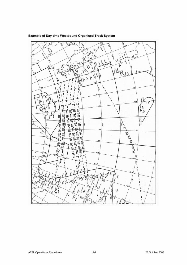
ATPL Operational Procedures 28 October 2003 19-4
Example of Day-time Westbound Organised Track System
ATPL Operational Procedures ©Atlantic Flight Training 19-5
EXAMPLE OF WESTBOUND NAT TRACK MESSAGE
(NAT-1/2 TRACKS FLS 310/ 390 INCLUSIVE OCTOBER 8/ 1130Z TO OCTOBER 8/ 1800Z PART ONE OF TWO PARTS- A 59/10 61/20 61/30 61/40 61/50 60/60 CIMAT EAST LVLS NIL WEST LVLS 310 320 330 340 350 360 390 EUR RTS WEST NIL NAR N464B N466B N468B N472B N474B- B 58/10 60/20 60/30 60/40 59/50 PRAWN YDP EAST LVLS NIL WEST LVLS 310 320 330 340 350 360 370 380 390 EUR RTS WEST NIL NAR N322B N328C N334B N336E N346A N348C N352C N356C N362B- C 57/10 59/20 59/30 58/40 56/50 SCROD VALIE EAST LVLS NIL WEST LVLS 310 320 330 340 350 360 370 380 390 EUR RTS WEST NIL NAR N242B N248B N250C N252B- D 56/10 58/20 58/30 57/40 55/50 OYSTR STEAM EAST LVLS NIL WEST LVLS 310 320 330 340 350 360 370 380 390 EUR RTS WEST NIL NAR N224C N228A N230B N232B- E 55/10 57/20 57/30 56/40 54/50 CARPE REDBY EAST LVLS NIL WEST LVLS 310 320 330 340 350 360 370 380 390 EUR RTS WEST NIL NAR N202B N206C N210C- END OF PART ONE OF TWO PARTS ) (NAT-2/2 TRACKS FLS 310/390 INCLUSIVE AUGUST 14/ 1130Z TO AUGUST 14/ 1800Z PART TWO OF TWO PARTS-
ATPL Operational Procedures 28 October 2003 19-6
F MASIT 56/20 56/30 55/40 53/50 YAY EAST LVLS NIL WEST LVLS 310 320 330 340 350 360 370 380 390 EUR RTS WEST VIA DEVOL NAR N184B N188B N192B- G 49/15 48/20 45/30 42/40 38/50 35/60 HENCH EAST LVLS NIL WEST LVLS 320 340 360 EUR RTS WEST VIA GUNSO NAR NIL REMARKS: 1. TRACK MESSAGE IDENTIFICATION NUMBER IS 281 AND OPERATORS ARE REMINDED TO INCLUDE THE TMI NUMBER AS PART OF THE OCEANIC CLEARANCE READBACK 2. MNPS AIRSPACE EXTENDS FROM FL285 TO FL420. OPERATORS ARE REMINDED THAT SPECIFIC MNPS APPROVAL IS REQUIRED TO FLY IN THIS AIRSPACE. IN ADDITION, RVSM APPROVAL IS REQUIRED TO FLY BETWEEN FL310 AND FL390 INCLUSIVE 3. EIGHTY PERCENT OF GROSS NAVIGATION ERRORS OCCUR AFTER A REROUTE. ALWAYS CARRY OUT WAYPOINT CROSS CHECKS END OF PART TWO OF TWO PARTS )
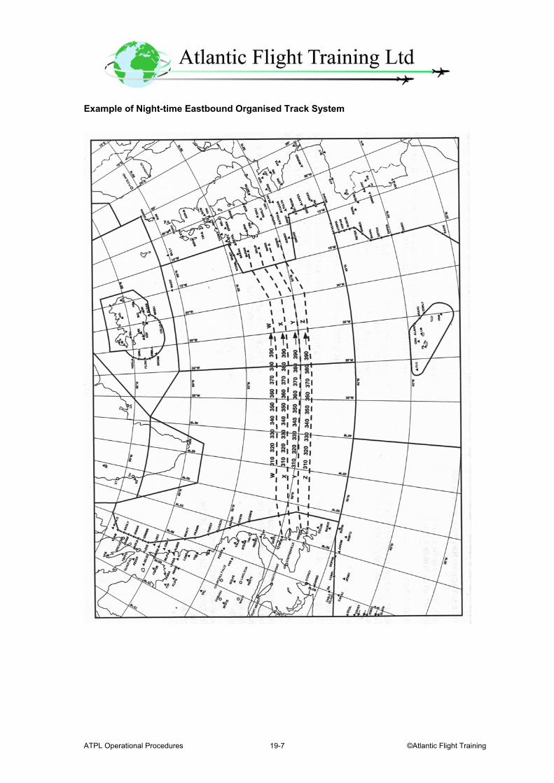
ATPL Operational Procedures ©Atlantic Flight Training 19-7
Example of Night-time Eastbound Organised Track System
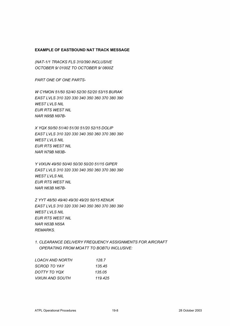
ATPL Operational Procedures 28 October 2003 19-8
EXAMPLE OF EASTBOUND NAT TRACK MESSAGE (NAT-1/1 TRACKS FLS 310/390 INCLUSIVE OCTOBER 9/ 0100Z TO OCTOBER 9/ 0800Z PART ONE OF ONE PARTS- W CYMON 51/50 52/40 52/30 52/20 53/15 BURAK EAST LVLS 310 320 330 340 350 360 370 380 390 WEST LVLS NIL EUR RTS WEST NIL NAR N95B N97B- X YQX 50/50 51/40 51/30 51/20 52/15 DOLIP EAST LVLS 310 320 330 340 350 360 370 380 390 WEST LVLS NIL EUR RTS WEST NIL NAR N79B N83B- Y VIXUN 49/50 50/40 50/30 50/20 51/15 GIPER EAST LVLS 310 320 330 340 350 360 370 380 390 WEST LVLS NIL EUR RTS WEST NIL NAR N63B N67B- Z YYT 48/50 49/40 49/30 49/20 50/15 KENUK EAST LVLS 310 320 330 340 350 360 370 380 390 WEST LVLS NIL EUR RTS WEST NIL NAR N53B N55A REMARKS. 1. CLEARANCE DELIVERY FREQUENCY ASSIGNMENTS FOR AIRCRAFT OPERATING FROM MOATT TO BOBTU INCLUSIVE: LOACH AND NORTH 128.7 SCROD TO YAY 135.45 DOTTY TO YQX 135.05 VIXUN AND SOUTH 119.425
ATPL Operational Procedures ©Atlantic Flight Training 19-9
2. TRACK MESSAGE IDENTIFICATION 282. REMINDED THAT MNPS APPROVAL IS REQUIRED TO FLY IN THIS AIRSPACE. IN ADDITION, RVSM APPROVAL IS REQUIRED TO FLY WITHIN THE NAT REGION BETWEEN FL310 AND FL390 INCLUSIVE. PLEASE REFER TO CANADIAN NOTAM 980097 OR A3797. 4. 80 PERCENT OF GROSS NAVIGATION ERRORS OCCUR AFTER A REROUTE. ALWAYS CARRY OUT WAYPOINT CROSS CHECKS. END OF PART ONE OF ONE PART)

ATPL Operational Procedures 28 October 2003 19-10
Intentionally Left Blank
ATPL Operational Procedures ©Atlantic Flight Training 20-1
Chapter 20.
The Polar Track Structure (PTS) General A Polar Track Structure (PTS) is used consisting of:
10 fixed tracks in Reykjavik CTA, and 5 fixed tracks through Bodø OCA.
The PTS tracks through Bodø OCA are a continuation of the PTS tracks in Reykjavik CTA. The routes are not mandatory. Operators proposing to fly between Europe and Alaska from FL310 to FL390 inclusive are recommended to submit flight plans in accordance with one of the promulgated PTS tracks. Abbreviated Clearances An abbreviated clearance may be issued to an aircraft to follow one of the polar tracks throughout its flight. When an abbreviated clearance is issued it includes:
Clearance limit, which will normally be destination airfield; The cleared track specified by the track code; The cleared flight level(s); and The cleared Mach Number (if required).
On receipt of an abbreviated clearance the pilot must read back the contents of the clearance message and in addition the full details of the track specified by the track code. Abbreviated Position Reports When operating on the PTS position reports may be abbreviated by replacing the normal latitude co-ordinate with the word 'Polar' followed by the track code.
Example “Position, Atlantic 422, Polar Romeo 20 West at 1620, Flight Level 330, Estimating Polar Romeo 40 West at 1718, Polar Romeo 69 West Next”
Unless otherwise required by ATC, a position report should be made at the significant points listed in the appropriate AIP for the relevant PTS track.
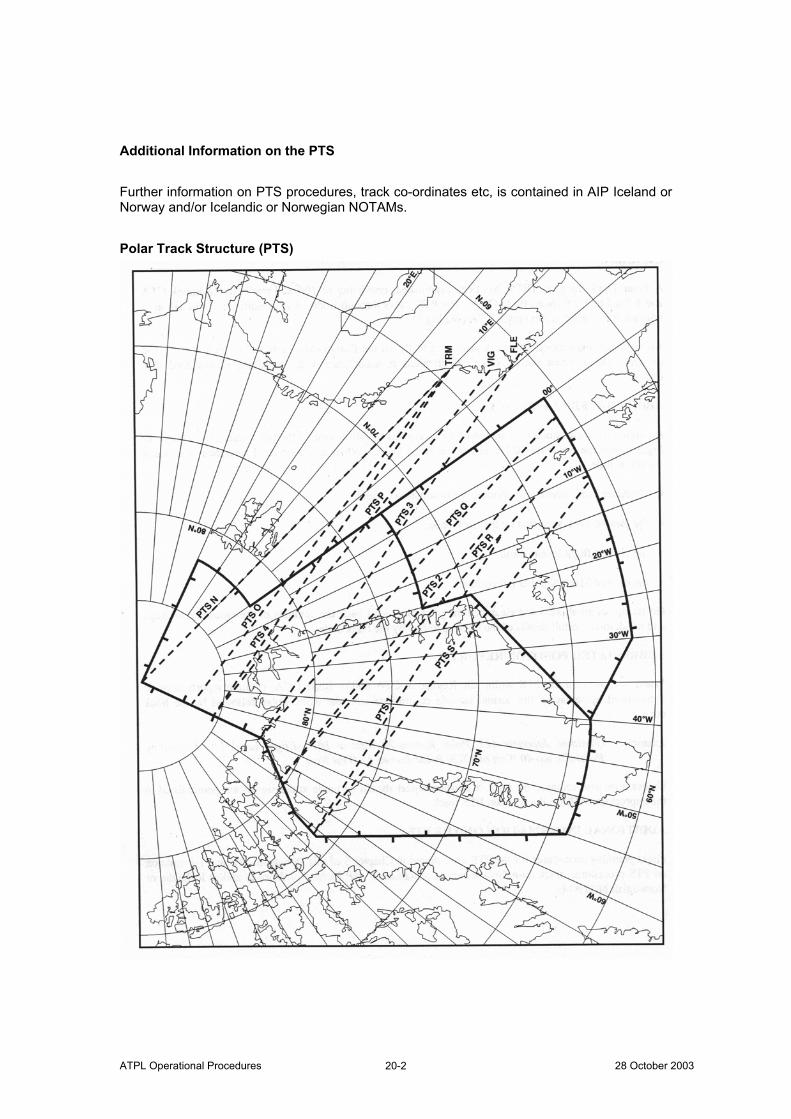
ATPL Operational Procedures 28 October 2003 20-2
Additional Information on the PTS Further information on PTS procedures, track co-ordinates etc, is contained in AIP Iceland or Norway and/or Icelandic or Norwegian NOTAMs. Polar Track Structure (PTS)
ATPL Operational Procedures ©Atlantic Flight Training 21-1
Chapter 21.
Other Routes and Route Structures Within or Adjacent to NAT MNPS Airspace
General The Organised Track System and the Polar Track Structure are the most significant route structures within NAT MNPS Airspace. Other route structures within and adjacent to MNPS Airspace are given below. Other Routes Within NAT MNPS Airspace Other routes within NAT MNPS Airspace illustrated on the next page are as follows:
1. A699 and A700 in the western part of the New York OCA; 2.* “Blue Spruce” Routes, established as special routes for aircraft equipped with only one serviceable LRNS. State approval for MNPS operations is required in order to fly along these routes.
3. Routes between Northern Europe and Spain/Canaries/Lisbon FIR. (T9*, T14
and T16); 4.* Routings between the Azores and the Portuguese mainland and between the
Azores and the Madeira Archipelago;
5. Special routes of short stage lengths where aircraft equipped with normal short-range navigation equipment can meet the MNPS track-keeping criteria (G3 and G11). State approval for MNPS operations is required in order to fly along these routes.
* Routes identified with an asterisk in sub paragraphs (2), (3) and (4) above may be flight planned and flown by approved aircraft equipped with normal short-range navigation equipment (VOR, DME, ADF) and at least one approved fully operational LRNS. Route Structures Adjacent to NAT MNPS Airspace Irish/UK Domestic Route Structures The UK AIP and AIP Ireland both specify the domestic routes to be used for westbound and eastbound NAT traffic based upon entry points into and exit points from oceanic airspace.
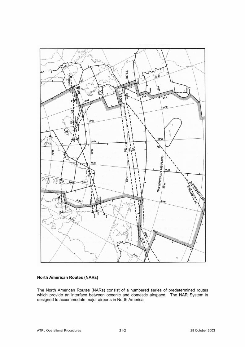
ATPL Operational Procedures 28 October 2003 21-2
North American Routes (NARs) The North American Routes (NARs) consist of a numbered series of predetermined routes which provide an interface between oceanic and domestic airspace. The NAR System is designed to accommodate major airports in North America.
ATPL Operational Procedures ©Atlantic Flight Training 21-3
Full details of all NAR routings together with associated procedures are published in the United States Airport Facility Directory - Northeast and the Canada Flight Supplement. Routes between North America and the Caribbean Area An extensive network of routes linking points in the United States and Canada with Bermuda, the Bahamas and the Caribbean area are defined in the New York OCA to the west of 60°W. This network is known as the Western Atlantic Route System (WATRS). Details of these routes and associated procedures are contained in the United States AIP. Shannon Oceanic Transition Area (SOTA) Part of the Shanwick OCA is designated as the Shannon Oceanic Transition Area (SOTA). MNPS Airspace requirements are still applicable from FL285 to FL420. SOTA has the same vertical extent as the Shanwick OCA, and is bounded by lines joining successively the following points:
N5100 W01500 – N5100 W00800 – N4830 W00800 – N4900 W01500 – N5100 W01500
SHANNON ACC using the call sign SHANNON CONTROL provides air Traffic Service. Full details of the service provided and the procedures used are contained in AIP Ireland. Brest Oceanic Transition Area (BOTA) Part of the Shanwick OCA is designated as the Brest Oceanic Transition Area (BOTA). MNPS Airspace requirements are still applicable from FL285 to FL420. BOTA has the same vertical extent as the Shanwick OCA, and is bounded by lines joining successively the following points:
N4834 W00845 – N4830 W00800 – N4500 W00800 – N4500 W00845 – N4834 W00845
Air Traffic service is provided by the Brest ACC, callsign BREST CONTROL.

ATPL Operational Procedures 28 October 2003 21-4
Intentionally Left Blank
ATPL Operational Procedures ©Atlantic Flight Training 22-1
Chapter 22.
Flight Planning Preferred Route Messages (PRMS) Oceanic planners take into consideration operators' preferred routes in the construction of the OTS. NAT operators should provide information regarding their proposed flights and optimum tracks during the peak traffic periods. The information should be provided as far in advance as possible, but not later than:
1900 UTC for the following day-time OTS and 1000 UTC for the following night-time OTS.
Flight Plan Requirements General All flights which generally route in:
An eastbound or westbound direction should normally be flight planned so that specified ten degrees of longitude (20°W, 30°W, 40°W etc.) are crossed at whole degrees of latitude; and
A northbound or southbound flights should normally be flight planned so that specified parallels of latitude spaced at five degree intervals (65°N, 60°N, 55°N etc.) are crossed at whole degrees of longitude.
All flights should plan to operate on great circle tracks joining successive significant waypoints. Routings During the hours of validity of the OTS, operators are encouraged to flight plan as follows:
In accordance with the OTS; or Along a route to join or leave an outer track of the OTS; or On a random route to remain clear of the OTS
Outside of the OTS periods operators may flight plan any random routing, except that during the two hours prior to each OTS period the following restrictions apply:
ATPL Operational Procedures 28 October 2003 22-2
1. Eastbound/Westbound flights that cross 30°W less than one hour prior to the incoming/pending OTS should plan to remain clear of the incoming/pending OTS structure.
2. Any opposite direction flights crossing 30°W between one and two hours prior
to the incoming OTS
Any eastbound flights between 0930 and 1029 UTC, or Any westbound flights between 2300 and 2359 UTC
where the route beyond 30°W would coincide with the incoming/pending OTS structure at any point, should plan to join an outer track at any point, or backtrack the length of one of the incoming/pending tracks.
Flight Levels Flight levels for use under RVSM are published in the UK and Canada AIPs, as the Flight Level Allocation Scheme (FLAS). The FLAS as published in the AIPs applies only to the current phase of NAT RVSM operations. Different flight level allocation schemes which apply when subsequent phases of RVSM operations are implemented will be similarly published as and when these new phases occur. During the OTS Periods (eastbound 0100-0800 UTC, westbound 1130-1800 UTC) aircraft intending to follow an OTS Track for its entire length may plan at any of the levels as published for that track on the current daily OTS Message. Flights which are planned to remain entirely clear of the OTS or which join or leave an OTS Track (i.e. follow an OTS track for only part of its published length), are all referred to as Random Flights. Pilots intending to fly on a random route or outside the OTS time periods should normally plan flight level(s) appropriate to the direction of flight. Appropriate Direction Levels These are specified by the Semi-circular Rule, ICAO Annex 2, Appendix 3.
NAT RVSM implementation (FL310-FL390 inclusive)
Appropriate Direction Eastbound levels are therefore: 270,290,310,330,350,370,390,410,450,etc
and
Appropriate Direction Westbound levels are therefore:
260,280,320,340,360,380,430,470,etc
ATPL Operational Procedures ©Atlantic Flight Training 22-3
ATC Flight Plans Flight plans for flights departing from points in other Regions and entering the NAT Region without intermediate stops should be submitted as far in advance of departure as possible. In order to signify that a flight is approved to operate in NAT MNPS Airspace:
The letter ‘X’ shall be inserted, in addition to the letter ‘S’, within Item 10 of the flight plan.
If the flight is approved to operate at RVSM levels a ‘W’ must also be included in Item 10.
For turbojet aircraft the Mach Number should be specified in Item 15 of the flight plan. Item 15 of the flight plan should reflect the proposed speeds in the following sequence:
Cruising True Airspeed (TAS); Oceanic entry point and cruising Mach Number; Oceanic landfall and cruising TAS.
Flight Planning Requirements on Specific Routes Flights Planning on the Organised Track System If the flight is planned to operate:
Along the entire length of one of the organised tracks the intended organised track is used in Item 15 of the flight plan using the abbreviation 'NAT' followed by the code letter assigned to the track.
Along part of, or leave, an organised track at some intermediate point it is considered to be a random route aircraft. Full route details must be specified in the flight plan and the track letter must not be used to abbreviate any portion of the route in these circumstances.
The planned Mach Number and flight level for the organised track should be specified at:
The last domestic reporting point prior to oceanic airspace entry or The organised track commencement point.
Geographical co-ordinates in latitude and longitude or as a named waypoint must specify each point at which a change of Mach Number or flight level is planned.
ATPL Operational Procedures 28 October 2003 22-4
For flights operating along the whole length of one of the organised tracks, estimates are only required for the commencement point of the track. Flights Planning on Random Route Segments at/or South of 70°N The requested Mach Number and flight level should be specified at either the last domestic reporting point prior to oceanic airspace entry or the OCA boundary. The route of flight should be specified in terms of the following significant points, with estimates included in Item 18 of the flight plan:
1. The last domestic reporting point prior to the oceanic entry point; 2. The OCA boundary entry point (only required by the Shanwick, New York
and Santa Maria OACs); 3. Significant points formed by the intersection of half or whole degrees of
latitude, with meridians spaced at intervals of ten degrees of longitude from the Zero degree E/W (Greenwich) Meridian to longitude 70oW;
4. The OCA boundary exit point (only required by the Shanwick, New York and Santa Maria OACs); and
5. The first domestic reporting point after ocean exit.
Each point at which a change of Mach Number or flight level is requested must be specified and followed in each case by the next significant point. Flights Planning on a Generally Eastbound or Westbound Direction on Random Route Segments North of 70oN Flight planning requirements are identical to those listed for flights on random route segments at/or south of 70°N except that the route should be specified at 20° longitude intervals at whole degrees of latitude to 60°W. Flights Planning on Random Routes in a Generally Northbound or Southbound Direction Flight planning requirements for flights are identical to those listed for flights operating on random route segments at/or south of 70°N except that the route should be specified in terms of whole degrees of longitude with specified parallels of latitude which are spaced at 5° intervals from 20°N to 90°N. Flights Planning on the Polar Track Structure (PTS) If the flight is planned to operate along the whole length of one of the Polar tracks, the intended track should be defined in Item 15 of the flight plan using the abbreviation 'PTS' followed by the track code.
ATPL Operational Procedures ©Atlantic Flight Training 22-5
Flights wishing to join or leave a polar track at some intermediate point are considered to be following a random route and full track details must be specified in the flight plan. The track code must not be used to abbreviate any portion of the route in these circumstances. Estimated times over significant points must be specified in Item 18 of the flight plan. The requested Mach Number and flight level should be specified at the commencement point of the PTS or at the NAT Oceanic boundary. Each point at which a Mach Number or flight level change is planned must be specified as geographical co-ordinates in latitude and longitude followed in each case by the abbreviation 'PTS' and the track code. Flights Planning to Operate Without HF Communications The carriage of HF communications is mandatory for flight in the Shanwick OCA. Aircraft with only functioning VHF communications equipment should plan their route outside the Shanwick OCA and ensure that they remain within VHF coverage of appropriate ground stations throughout the flight.

ATPL Operational Procedures 28 October 2003 22-6
Intentionally Left Blank
ATPL Operational Procedures ©Atlantic Flight Training 23-1
Chapter 23.
Oceanic ATC Clearances General Oceanic Clearances are required for all flights within the NAT Airspace at or above FL55. Pilots should request Oceanic Clearances from the ATC unit responsible for the first OCA within which they wish to fly. The clearances are applicable only from the entry point. Pilots should request their Oceanic Clearance at least 40 minutes prior to the Oceanic entry point ETA and, if requesting an OTS track, should include the next preferred alternative. When requesting an oceanic clearance the pilot should notify the OAC of the maximum acceptable flight level possible at the boundary; the aircraft must be within radar coverage during any climb. The pilot must notify the OAC of any required change to:
The oceanic flight planned level Track or Mach Number
Methods of obtaining Oceanic Clearances include:
1. Use of published VHF clearance delivery frequencies; 2. By HF communications to the OAC through the appropriate radio station (at
least 40 minutes before boundary/entry estimate); 3. A request via domestic or other ATC agencies; 4. By data link, when arrangements have been made with designated airlines to
request and receive clearances using on-board equipment. At some airports situated close to oceanic boundaries, the Oceanic Clearance must be obtained before departure. If an aircraft has a critical in-flight equipment failure en-route to the NAT Oceanic Airspace, or at dispatch is unable to meet the MEL requirements for RVSM or MNPS approval on the flight, then the pilot must advise ATC at initial contact when requesting Oceanic Clearance. After obtaining and reading back the clearance, the pilot should monitor the forward estimate for oceanic entry and if this changes by 3 minutes or more should pass a revised estimate to ATC. If the cleared oceanic route differs from the original request and/or the oceanic flight level differs from the current flight level, the pilot is responsible for obtaining the necessary domestic reclearance to ensure that the flight complies with its Oceanic Clearance when entering oceanic airspace.
ATPL Operational Procedures 28 October 2003 23-2
There are three elements to an Oceanic Clearance:
route, Mach Number and flight level.
These elements serve to provide for the three basic elements of separation: lateral, longitudinal and vertical. The Oceanic Clearance issued to each aircraft is at a specific flight level and cruise Mach Number. Flight level or Mach Number changes should not normally be made without prior ATC clearance. Prior to reaching the Shanwick OCA boundary, if pilots have not received their Oceanic Clearance then they are to remain clear of Oceanic Airspace whilst awaiting the Clearance. This is not the case for other NAT OCAs where flights may enter whilst pilots are awaiting receipt of a delayed Oceanic Clearance. An example of a pilot voice request for Oceanic Clearance is as follows: “Atlantic 442 request Oceanic Clearance. Estimating 56N010W at 1131. Request Mach decimal eight zero, Flight Level three five zero, able Flight Level three six zero, second choice Track Charlie”. If the request also includes a change to the original flight plan, affecting the OCA, then it should be according to the following example: “Atlantic 442 request Oceanic Clearance. Estimating 55N010W at 1147. Request Mach decimal eight zero, Flight Level three four zero. Now requesting Track Charlie, able Flight Level three six zero, second choice Track Delta”. Contents of Clearances An abbreviated clearance is issued by Air Traffic Services when clearing an aircraft to fly along the whole length of an Organised Track, or along a Polar Track within the Reykjavik CTA and/or Bodø OCA. When an abbreviated clearance is issued it includes:
Clearance Limit, which will normally be destination airfield; Cleared track specified as “Track” plus code letter, or “Polar Track” plus code
identification; Cleared flight level(s); Cleared Mach Number; and If the aircraft is designated to report Met information en route, the phrase “SEND MET
REPORTS”.
ATPL Operational Procedures ©Atlantic Flight Training 23-3
Procedures exist for an abbreviated read back of an Oceanic Clearance issued on VHF. A typical example of such a clearance is as follows: “Atlantic 442 is cleared to Toronto via Track Bravo, from 56N010W maintain Flight Level three five zero, Mach decimal eight zero”. The flight crew will confirm that they are in possession of the current NAT Track message by using the TMI number in the read-back of the Oceanic Clearance, as follows: “Atlantic 442 is cleared to Toronto via Track Bravo 283, from 56N010W maintain Flight Level three five zero, Mach decimal eight zero”. If the TMI number is included in the read-back there is no requirement for the pilot to read back the NAT Track co-ordinates even if the cleared NAT Track is not the one which was originally requested. If any doubt exists as to the TMI or the NAT Track co-ordinates, the pilot should request the complete track co-ordinates from the OAC. Similarly, if the pilot cannot correctly state the TMI, the OAC will read the cleared NAT Track co-ordinates in full and request a full read back of those co-ordinates. Oceanic Clearances For Flights Intending To Operate Within The NAT Region And Subsequently Enter The EUR Or NAM Regions Oceanic Clearances issued to most flights in this category are strategic clearances intended to provide a safe separation for each flight, from oceanic entry to oceanic track termination point. If a pilot receives a clearance on a track other than originally flight planned he must check that the landfall and domestic routeings are fully understood. Oceanic Clearances For Random Flights Intending To Operate Within The NAT Region And Subsequently Enter Regions Other Than NAM Or EUR Oceanic Clearances issued to flights in this category are similar to domestic ATC clearances in that clearances are to destination on the assumption that co-ordination will be effected ahead of the aircraft's passage. In this case, the flight profile may be changed en-route, prior to hand-over from one centre to another, depending upon traffic conditions in the adjacent area. Oceanic Flights Originating From the CAR or SAM Regions And Entering NAT MNPS Airspace Via The New York OCA Pilots are reminded that Oceanic Clearances from the New York OAC do not need to be requested until first contact with New York is established on HF frequencies. Note that Oceanic Clearances are not required for entry to or transit of that portion of the New York OCA outside MNPS Airspace.
ATPL Operational Procedures 28 October 2003 23-4
Errors Associated With Oceanic Clearances Navigation errors associated with Oceanic Clearances fall into several categories of which the most significant are ATC System Loop errors and Waypoint Insertion errors. Waypoint Insertion Errors Experience has shown that many of the track keeping errors which occur result from:
Failure to observe the principles of checking waypoints to be inserted in the navigation systems, against the ATC cleared route;
Failure to load waypoint information carefully; or Failure to cross-check on-board navigation systems.
ATPL Operational Procedures ©Atlantic Flight Training 24-1
Chapter 24.
Communications and Position Reporting Procedures HF Communications Most NAT air/ground communications are conducted on single side-band HF frequencies. VHF Communications The carriage of HF communications equipment is mandatory for flight in the Shanwick OCA. Aircraft with only functioning VHF communications equipment should plan their route outside the Shanwick OCA and ensure that they remain within VHF coverage of appropriate ground stations throughout the flight. Time and Place of Position Reports Unless otherwise requested by Air Traffic Control, position reports from flights on routes which are not defined by designated reporting points should be made at the significant points listed in the flight plan. Air Traffic Control may require any flight operating in a North/South direction to report its position at any intermediate parallel of latitude when necessary. In requiring aircraft to report their position at intermediate points, ATC is guided by the requirement to have position information at approximately hourly intervals and also by the need to cater for varying types of aircraft and varying traffic and MET conditions. Pilots must always report to ATC as soon as possible on reaching any new cruising level. Contents of Position Reports For flights outside the PTS and domestic ATS route network, position should be expressed in terms of latitude and longitude except when flying over named reporting points. For flights whose tracks are predominantly east or west, latitude should be expressed in degrees and minutes, longitude in degrees only. For flights whose tracks are predominantly north or south, latitude should be expressed in degrees only, longitude in degrees and minutes. All times should be expressed in four digits giving both the hour and the minutes UTC. Reporting procedures for PTS flights have already been described in an earlier chapter.
ATPL Operational Procedures 28 October 2003 24-2
Standard Message Types Standard air/ground message types and formats are used within the NAT Region and are published in State AIPs and Atlantic Orientation charts. To enable ground stations to process messages in the shortest possible time, pilots should observe the following rules:
1. Use the correct type of message applicable to the data transmitted; 2. State the message type in the contact call to the ground station or at the start
of the message; 3. Adhere strictly to the sequence of information for the type of message; 4. All times in any of the messages should be expressed in hours and minutes UTC.
The message types are shown below with examples:
POSITION example: “Position, Atlantic 442, 56 North 10 West at 1235, Flight Level 330, Estimating 56 North 20 West at 1310, 56 North 30 West Next” REQUEST CLEARANCE example: “Request Clearance, Atlantic 442, 56 North 20 West at 1308, Flight Level 330, Estimating 56 North 30 West at 1340, 56 North 40 West Next. Request Flight Level 350” or if a position report is not required “Request Clearance, Atlantic 442, Request Flight Level 370” REVISED ESTIMATE example: “Revised Estimate, Atlantic 442, 57 North 40 West at 0305” MISCELLANEOUS Plain language – free format
Addressing Of Position Reports Position reports made by aircraft operating within an OCA at a distance of 60 nm or less from the boundary with an adjacent OCA, including aircraft operating on tracks through successive points on each boundary, should also be made to the ACC serving the adjacent OCA using the message “Shanwick copy Santa Maria”.
ATPL Operational Procedures ©Atlantic Flight Training 24-3
“When Able Higher” (WAH) Reports Prior advice to ATC of the time or position that a flight will be able to accept the next higher level can assist ATC in ensuring optimum use of available altitudes. These reports can also be used to help plan the altitudes for flights as they transition from RVSM to conventional altitudes. A WAH Report must be provided by all flights entering the MNPS Airspace portion of the New York OCA and entering the Santa Maria OCA. Provision of WAH Reports on entering other NAT OCAs is optional or they may be requested by any OAC. When entering an oceanic FIR, pilots should include in the initial position report the time or location that the flight will be able to accept the next higher altitude. The report may include more than one altitude if that information is available.
example: ”Atlantic 442, 40 North 40 West at 1010, Flight Level 350, Estimating 40 North 50 West at 1110, 40 North 60 West Next. Able Flight Level 360 at 1035, Able Flight Level 370 at 1145, Able Flight Level 390 at 1300”
Information thus provided of the aircraft’s future altitude “ability” will not automatically be interpreted by ATC as an advance “request” for a step climb. It will be used as previously indicated to assist ATC in planning airspace utilisation. However, should the pilot wish to register a request for one or more future step climbs, this may be incorporated in the WAH report by appropriately substituting the word “Request” for the word “Able”.
example: “Atlantic 442, 42 North 40 West at 1215, Flight Level 330, Estimating 40 North 50 West at 1310, 38 North 60 West Next. Request Flight Level 340 at 1235, Able Flight Level 350 at 1325, Request Flight Level 360 at 1415”
Although optimal use of the WAH reports is in conjunction with a Position Report, a WAH report can be made or updated separately at any time.
example: “Atlantic 442, Able Flight Level 360 at 1035, Request Flight Level 370 at 1145, Able Flight Level 390 at 1300”
ATC acknowledgement of a WAH report (and any included requests) is NOT a clearance to change altitude. Meteorological Reports From among the aircraft intending to operate on the organised track system, OACs designate those which will be required to report routine meteorological observations at, and midway between, each prescribed reporting point. The designation is made by the OAC when issuing the Oceanic Clearance using the phrase “SEND MET REPORTS“, and is normally made so as to designate one aircraft per track at approximately hourly intervals. Pilots flying tracks partly or wholly off the OTS should include routine Met observations with every prescribed report. The midpoint observation should be recorded then transmitted at the next designated reporting point.
ATPL Operational Procedures 28 October 2003 24-4
SELCAL When using HF communications, pilots should maintain a listening watch on the assigned frequency, unless SELCAL is fitted, in which case they should ensure the following sequence of actions:
1. Provision of the SELCAL code in the flight plan; (any subsequent change of
aircraft for a flight will require passing the new SELCAL information to the OAC);
2. Checking the operation of the SELCAL equipment, at or prior to entry into Oceanic airspace, with the appropriate radio station. (This SELCAL check must be completed prior to commencing SELCAL watch); and
3. Maintenance thereafter of a SELCAL watch. General Purpose VHF Communications (GP/VHF) Radio stations are also responsible for the operation of GP/VHF outlets. It is important for the pilot to appreciate that when using GP/VHF communications they are with a radio station and not by direct contact with ATC. However Direct Controller/Pilot Communications (DCPC) can be arranged if necessary on some GP/VHF frequencies. Data Link Communications Data link communications are gradually being introduced into the NAT environment for position reporting. AIS publications of the NAT ATS Provider States should be consulted to determine the extent of their implementation and any associated procedures. HF Communications Failure Each radio station continuously listens out on its appropriate family/families of NAT HF frequencies. In the event of failure of HF communications every effort should be made by the pilot to relay position reports through other aircraft. An air-to-air VHF frequency for the Region has been agreed; when out of range of VHF ground stations on the same or adjacent frequencies, 123.45 MHz may be used to relay position reports. If necessary initial contact for such relays can be established on 121.5 MHz - although great care must be exercised should this be necessary, as the frequency 121.5 MHz is monitored by all aircraft operating in the NAT Region, in case it is being used by aircraft experiencing emergencies. Therefore in order to minimise unnecessary use of 121.5 MHz, it is recommended that aircraft additionally monitor 123.45 MHz when flying through NAT airspace. General If so equipped, the pilot of an aircraft experiencing a two way communications failure should operate the SSR Transponder on identity Mode A Code 7600 and Mode C.
ATPL Operational Procedures ©Atlantic Flight Training 24-5
The pilot should attempt to contact any ATC facility or another aircraft and inform them of the difficulty and request they relay information to the ATC facility with whom communications are intended. Communications Failure Prior to Entering NAT Region Due to the potential length of time in oceanic airspace, it is strongly recommended that a pilot experiencing communications failure whilst still in domestic airspace does not enter the OCA but adopts the procedure specified in the appropriate domestic AIP and lands at a suitable airport. However, if the pilot elects to continue, then, to allow ATC to provide adequate separation, one of the following procedures should be followed:
1. If operating with a received and acknowledged Oceanic Clearance, the pilot must enter oceanic airspace at the cleared oceanic entry point, level and speed and proceed in accordance with the received and acknowledged Oceanic Clearance. Any level or speed changes required to comply with the Oceanic Clearance must be completed within the vicinity of the oceanic entry point.
2. If operating without a received and acknowledged Oceanic Clearance, the pilot must enter oceanic airspace at the first oceanic entry point, level and speed contained in the filed flight plan and proceed via the filed flight plan route to landfall. The initial oceanic level and speed must be maintained until landfall.
Communications Failure After Entering NAT Region If cleared on the filed flight plan route, the pilot must proceed in accordance with the last received and acknowledged Oceanic Clearance, including level and speed, to the last specified oceanic route point (normally landfall) then continue on the filed flight plan route. After passing the last specified oceanic route point, the flight should conform with the relevant State procedures/regulations. If cleared on other than the filed flight plan route, the pilot must proceed in accordance with the last received and acknowledged Oceanic Clearance, including level and speed, to the last specified oceanic route point (normally landfall). After passing this point, the pilot should conform with the relevant State procedures/regulations, rejoining the filed flight plan route by proceeding, via the published ATS route structure where possible, to the next significant point contained in the filed flight plan. The relevant State procedures/regulations to be followed by an aircraft in order to rejoin its filed Flight Plan route are specified in detail in the appropriate State AIP. Aircraft with a destination within the NAT Region should proceed to their clearance limit and follow the ICAO standard procedure to commence descent from the appropriate designated navigation aid serving the destination aerodrome at, or as close as possible to, the expected approach time. Detailed procedures are promulgated in relevant State AIPs.
ATPL Operational Procedures 28 October 2003 24-6
Operation of Transponders Unless otherwise directed by ATC, pilots of aircraft equipped with SSR transponders flying in the NAT FIRs will operate transponders continuously in Mode A/C Code 2000, except that the last assigned code will be retained for a period of 30 min after entry into NAT airspace. Pilots should note that it is important to change from the last assigned domestic code to the Mode A/C Code 2000 since the original domestic code may not be recognised by the subsequent Domestic Radar Service on exit from the oceanic airspace. This procedure does not affect the use of the special purpose codes (7500, 7600 and 7700) in cases of:
unlawful interference, radio failure, emergency.
Airborne Collision Avoidance Systems (ACAS) Pilots should report all ACAS Resolution Advisories which occur in the NAT Region to the controlling authority for the airspace involved.
ATPL Operational Procedures ©Atlantic Flight Training 25-1
Chapter 25.
Application of Mach Number Technique
Description of Terms ‘Mach Number Technique’ describes the technique where subsonic turbojet aircraft are cleared by ATC to maintain an appropriate Mach Numbers for a portion of the en-route phase of their flight. Objective The objective of the use of Mach Number Technique is to achieve improved utilisation of the airspace on long route segments where ATC has no means other than position reports of ensuring that the longitudinal separation between successive aircraft is not reduced below the established minimum Procedures in NAT Oceanic Airspace The ATC clearance will include the assigned Mach Number to be maintained. Information on the desired Mach Number is included in the flight plan for turbojet aircraft intending to fly in NAT oceanic airspace. ATC uses Mach Number together with pilot position reports to calculate estimated times for significant points along track. These times provide the basis for longitudinal separation between aircraft and for co-ordination with adjacent ATC units. Longitudinal separation between successive aircraft flying a particular track at the same flight level is started from the oceanic entry point. Following aircraft on the same track can be assigned different Mach Numbers. These are to ensure that prescribed separations are assured throughout the oceanic crossing. Intervention by ATC is only necessary if an aircraft is required to change its Mach Number due to conflicting traffic or to change its flight level. Procedure After Leaving Oceanic Airspace After leaving oceanic airspace pilots must maintain their assigned Mach Number in domestic controlled airspace until the appropriate ATC unit authorises a change.

ATPL Operational Procedures 28 October 2003 25-2
Intentionally Left Blank
ATPL Operational Procedures ©Atlantic Flight Training 26-1
Chapter 26.
MNPS Flight Operation & Navigation Procedures General Procedures Importance of Accurate Time The proper operation of a correctly functioning LRNS will ensure that the aircraft follows its cleared track. ATC applies standard separations between cleared tracks and assures the safe lateral separation of aircraft. Longitudinal separations between subsequent aircraft following the same track and between aircraft on intersecting tracks are assessed in terms of differences in ETAs/ATAs at common waypoints. Aircraft clock errors resulting in position report time errors can lead to a shortening of longitudinal separation between aircraft. Prior to entry into the NAT MNPS Airspace the time reference system to be used during the flight must be accurately synchronised to UTC and that the calculation of waypoint ETAs and the reporting of waypoint ATAs are referenced to this system. Pre-flight Procedures for any NAT MNPS flight must include a UTC time check and resynchronisation of the aircraft master clock. Lists of acceptable time sources for this purpose have been promulgated by NAT ATS Provider States. The following are examples of acceptable time standards:
1. GPS (Corrected to UTC) 2. WWV - National Institute of Standards (NIST - Fort Collins, Colorado). WWV
operates continually H24 on 2500, 5000, 10,000, 15,000 and 20,000 kHz (AM/SSB) and provides UTC (voice) once every minute.
3. CHU - National Research Council (NRC - Ottawa, Canada) - CHU operates continually H24 on 3330, 7335 and 14,670 kHz (SSB) and provides UTC (voice) once every minute (English even minutes, French odd minutes).
4. BBC - British Broadcasting Corporation (United Kingdom). The BBC transmits on a number of domestic and worldwide frequencies and transmits the Greenwich time signal (referenced to UTC) once every hour on most frequencies, although there are some exceptions.
The Use of a Master Document Navigation procedures must include the use of a master working document to be used on the flight deck. This document may be based upon:
the flight plan, navigation log, or other suitable document
which lists sequentially the waypoints defining the route, the track and distance between each waypoint, and other information relevant to navigation along the cleared track.
ATPL Operational Procedures 28 October 2003 26-2
Misuse of the Master Document can result in GNEs occurring and for this reason strict procedures regarding its use should be established. These procedures should include the following:
Only one Master Document to be used on the flight deck. However, this does not preclude other crewmembers maintaining a separate flight log.
On INS equipped aircraft a waypoint numbering sequence should be established from the outset of the flight and entered on the Master Document. The identical numbering sequence should be used for storing waypoints in the navigation computers.
For aircraft equipped with FMS databases, FMS generated or inserted waypoints should be carefully compared to Master Document waypoints and cross checked by both pilots.
An appropriate symbology should be adopted to indicate the status of each waypoint listed on the Master Document.
GPS Operational Control Restrictions Any predicted satellite outages that affect the capability of GPS navigation may require that the flight be cancelled, delayed or re-routed. Effects of Satellite Availability Given suitable geometry:
Four appropriately configured satellites are required to determine position; Five appropriately configured satellites are required to detect the presence of a single
faulty satellite; and Six appropriately configured satellites are required to identify the faulty satellite and
exclude it from the navigation solution. The above number of satellites may be reduced if barometric aiding is used. Flight Plan Check The purpose of this check is to ensure complete compatibility between the data in the Master Document and the calculated output from the navigation systems. Typical actions could include:
Checking the distance from the ramp position to the first waypoint. Selecting track waypoint 1 to waypoint 2 and doing the following:
checking accuracy of the indicated distance against that in the Master Document; checking, if possible, that the track displayed is the same in the Master Document
ATPL Operational Procedures ©Atlantic Flight Training 26-3
Similar checks should be carried out for subsequent pairs of waypoints and any discrepancies between the Master Document and displayed data checked for possible waypoint insertion errors.
When each leg of the flight has been checked in this manner it should be annotated on the Master Document
In Flight Procedures Initial flight During the initial part of the flight, ground navaids should be used to verify the performance of the LRNSs. ATC Oceanic Clearance Two flight crewmembers should listen to and record every ATC clearance. Any doubt should be resolved by requesting clarification from ATC. Entering the MNPS Airspace and Reaching an Oceanic Waypoint When passing waypoints, the following checks should be carried out:
Just prior to the waypoint, check the present position co-ordinates of each navigation system against the cleared route in the Master Document, and
Check the next two waypoints in each navigation system against the Master Document.
At the waypoint, check the distance to the next waypoint, confirm that the aircraft turns in the correct direction and takes up a new heading and track appropriate to the leg to the next waypoint.
Before transmitting the position report to ATC, verify the waypoint co-ordinates against the Master Document and those in the steering navigation system. When feasible the position report “next” and “next plus 1” waypoint co-ordinates should be read from the CDU of the navigation system coupled to the autopilot.
Approaching Landfall When the aircraft is within range of land based navaids, and the crew is confident that these navaids are providing reliable navigation information, consideration should be given to updating the LRNSs.
ATPL Operational Procedures 28 October 2003 26-4
Special In Flight Procedures Avoiding Confusion between Magnetic and True Track Reference Crews who decide to check or update their LRNSs by reference to VORs should remember that in the Canadian Northern Domestic Airspace these may be oriented with reference to true north, rather than magnetic north. Navigation in the Area of Compass Unreliability In areas of compass unreliability basic inertial navigation requires no special procedures but most operators feel it is desirable to retain an independent heading reference in case of system failure. (Where the magnetic field is less than 6 micro teslars)
ATPL Operational Procedures ©Atlantic Flight Training 27-1
Chapter 27.
Procedures for Flight at RVSM Levels in MNPS Airspace General Aircraft altimetry systems necessary for flying at RVSM levels must be capable of high-performance standards. Pre-Flight If following a failure of an air data computer (ADC), both the Captain’s and Co-pilot’s altimeter instruments are connected to a remaining single functional ADC, this arrangement does not meet the RVSM MASPS requirement for two independent primary altimetry systems. Any previously granted RVSM Approval is therefore invalidated until corrective action has been taken. A ‘W’ must be entered into Item 10 of the ICAO flight plan to indicate that the aircraft is approved for flight at RVSM levels; the letter ‘X’ must still be included to show that the aircraft satisfies MNPS lateral navigation performance requirements. Pre-flight checks of the altimeters must be conducted and it is essential that all altitude indications are within the tolerances specified in the aircraft operating manual. In-Flight - Before Operating at RVSM Levels Confirmation is necessary that aircraft serviceability still allows flight to be made in RVSM airspace. An altimeter crosscheck should be carried out shortly before entering RVSM airspace; at least two primary altimeters must agree within plus or minus 200 ft. In-Flight - Entering, Flying at and leaving RVSM Levels One automatic altitude-control system should be operative and engaged throughout the cruise. This system should only be disengaged when it is necessary to
Retrim the aircraft, or When the aircraft encounters turbulence and Operating procedures dictate.
When passing waypoints, or at intervals not exceeding 60 minutes, a cross-check of primary altimeters should be conducted. If at any time the readings of the two primary altimeters differ by more than 200 ft, the aircraft’s altimetry system should be considered unserviceable and ATC must be informed as soon as possible.
ATPL Operational Procedures 28 October 2003 27-2
When changing flight levels within RVSM airspace all vertical speeds should be within 500 to 1000 ft per minute. This can reduce the likelihood of TCAS TAs and RAs occurring and should also help to ensure that the aircraft neither undershoots nor overshoots the cleared flight level by more than 150 feet. Equipment Failures The following equipment failures must be reported to ATC as soon as practicable following their identification:
Loss of one or more primary altimetry systems; or Failure of all automatic altitude-control systems
The aircraft should then follow the appropriate procedure described in Chapter 28, “Special Procedures for In-Flight Contingencies”, or as instructed by the controlling ATC unit. Vertical Navigation Performance Monitoring Operational errors, particularly those in the vertical plane, can have a significant effect on risk in the system. For their safety and the safety of other users, crews are reminded of the importance of co-operating with the reporting OAC in the compilation of appropriate documentation including the completion of an “Altitude Deviation Report Form”.
ATPL Operational Procedures ©Atlantic Flight Training 28-1
Chapter 28.
Procedures in the Event of Navigation System Degradation or Failure General The navigation systems fitted to MNPS approved aircraft are generally very accurate and very reliable and GNEs in NAT MNPS Airspace are rare. For unrestricted operation in MNPS Airspace an approved aircraft must be equipped with a minimum of two fully serviceable LRNSs. MNPS approved aircraft that have suffered any equipment failures that result in only a single LRNS remaining serviceable may still be flight planned and flown through the MNPS Airspace but only on specified routes established for this purpose. Crew training and consequent approval for MNPS operations should include instruction on what actions are to be considered in the event of navigation system failures. Detection of Failures Normally, navigation installations include comparator and/or warning devices, but it is still necessary for the crew to make frequent comparison checks. When an aircraft is fitted with three independent systems, the identification of a defective system should be straightforward. Methods of Determining which System is Faulty With only two systems on board, identifying the defective unit can be difficult. If such a situation does arise in oceanic airspace any or all of the following actions should be considered:
Checking malfunction codes for indication of unserviceability. Obtaining a fix. It may be possible to use the following:
The weather radar (range marks and relative bearing lines) to determine the
position relative to an identifiable landmark such as an island; or The ADF to obtain bearings from a suitable NDB, A VOR Contacting a nearby aircraft on VHF, and comparing information on spot wind, or
ground speed and drift.
If such assistance is not available, and as a last resort, the flight plan wind speed and direction for the current DR position of the aircraft, can be compared with that from navigation system outputs.
ATPL Operational Procedures 28 October 2003 28-2
Guidance on What Constitutes a Failed System Operations or navigation manuals should include guidelines on how to decide when a navigation system should be considered to have failed. If there is a difference greater than 15 nm between two aircraft navigation systems it is advisable to split the difference between the readings when determining the aircraft's position. If the disparity exceeds 25 nm one or more of the navigation systems should be regarded as having failed, in which case ATC should be notified. GPS Satellite Fault Detection Outage If the GPS receiver displays an indication of a fault detection function outage (i.e. RAIM is not available), navigation integrity must be provided by comparing the GPS position with the position indicated by another LRNS sensor. If the only sensor for the approved LRNS is GPS, then comparison should be made with a position computed by extrapolating the last verified position with airspeed, heading and estimated winds. If the positions do not agree within 10 nm, the pilot should adopt navigation system failure procedures, until the exclusion function or navigation integrity is regained, and should report degraded navigation capability to ATC. Partial or Complete Loss Of Navigation/FMS Capability By Aircraft Having State Approval For Unrestricted Operations In MNPS Airspace Some aircraft carry triplex equipment (3 LRNSs) and hence if one system fails, even before take off, the two basic requirements for MNPS Airspace operations may still be met and the flight can proceed normally. The following guidance is offered for aircraft equipped with only two operational LRNSs: One System Fails Before Take-Off The pilot should consider:
Delaying departure if timely repair is possible; Obtaining a clearance above or below MNPS Airspace;
Planning on the special routes known as the ‘Blue Spruce’ Routes Use of the above routes is subject to:
Sufficient navigation capability remains to ensure that MNPS accuracy can be met by relying on short-range navaids;
A revised flight plan is filed with the appropriate ATS unit; An appropriate ATC clearance is obtained.
ATPL Operational Procedures ©Atlantic Flight Training 28-3
One System Fails Before the OCA Boundary is Reached The pilot must consider:
Landing at a suitable aerodrome before the boundary or returning to the aerodrome of departure;
Diverting via one of the special routes described previously; Obtaining a reclearance above or below MNPS Airspace.
One System Fails After the OCA Boundary is Crossed Once the aircraft has entered oceanic airspace, the pilot should normally continue to operate the aircraft in accordance with the Oceanic Clearance already received, appreciating that the reliability of the total navigation system has been significantly reduced. The pilot should however,
Assess the prevailing circumstances in MNPS Airspace, etc.; Prepare a proposal to ATC with respect to the prevailing circumstances; Advise and consult with ATC as to the most suitable action; Obtain appropriate reclearance prior to any deviation from the last acknowledged
Oceanic Clearance.
When the flight continues in accordance with its original clearance (especially if the distance ahead within MNPS Airspace is significant), the pilot should begin a careful monitoring programme:
To take special care in the operation of the remaining system bearing in mind that routine methods of error checking are no longer available;
To check the main and standby compass systems frequently against the information which is still available;
To check the performance record of the remaining equipment and if doubt arises regarding its performance and/or reliability, the following procedures should be considered:
Attempting visual sighting of other aircraft or their contrails, which may
provide a track indication; Calling the appropriate OAC for information on other aircraft adjacent to
the aircraft’s estimated position and/or calling on VHF to establish contact with such aircraft (preferably same track/level) to obtain from them information which could be useful. e.g. drift, groundspeed, wind details.
ATPL Operational Procedures 28 October 2003 28-4
The Remaining System Fails After Entering MNPS Airspace The pilot should:
Immediately notify ATC; Make best use of procedures specified above relating to attempting visual
sightings and establishing contact on VHF with adjacent aircraft for useful information;
Keep a special look-out for possible conflicting aircraft, and make maximum use of exterior lights;
If no instructions are received from ATC within a reasonable period consider climbing or descending 500 feet, broadcasting action on 121.5 MHz and advising ATC as soon as possible.
This procedure also applies when the remaining system gives an indication of degradation of performance, or neither system fails completely but the system indications diverge widely and the defective system cannot be determined. Complete Failure of Navigation Systems Computer A characteristic of the navigation computer system is that the computer element might fail, and thus deprive the aircraft of steering guidance and the indication of position relative to cleared track, but the basic outputs of the IRS (LAT/LONG, Drift and Groundspeed) are left unimpaired. A typical drill to minimise the effects of a total navigation computer system failure is suggested below. It requires the carriage of a suitable plotting chart.
Draw the cleared route on a chart and extract mean true tracks between waypoints.
Use the basic IRS/GPS outputs to adjust heading to maintain mean track and to calculate ETAs.
At intervals of not more than 15 minutes plot position (LAT/LONG) on the chart and adjust heading to regain track.
ATPL Operational Procedures ©Atlantic Flight Training 29-1
Chapter 29.
Special Procedures for In-Flight Contingencies Introduction The following procedures are intended for guidance only. Although all possible contingencies cannot be covered, they provide for such cases as:
Inability to maintain assigned level due to weather (for example severe turbulence);
Aircraft performance problems; or Pressurisation failure.
They are applicable primarily when rapid descent, turn-back, or diversion to an alternate aerodrome is required. The pilot's judgement will determine the specific sequence of actions taken, having regard to the prevailing circumstances. General Procedures If an aircraft is unable to continue its flight in accordance with its ATC clearance, a revised clearance should be obtained whenever possible, prior to initiating any action, using the radio telephony distress (MAYDAY, MAYDAY, MAYDAY) signal or urgency (PAN PAN, PAN PAN, PAN PAN) signal as appropriate. If prior clearance cannot be obtained, an ATC clearance should be obtained at the earliest possible time and, in the meantime, the aircraft should broadcast its position (including the ATS Route designator or the Track Code as appropriate) and its intentions, at frequent intervals on 121.5 MHz (with 123.45 MHz as a back-up frequency). Until a revised clearance is obtained the specified NAT in-flight contingency procedures should be carefully followed. The aircraft should be flown at a flight level and/or on a track where other aircraft are least likely to be encountered. Maximum use of aircraft lighting should be made and a good lookout maintained. If TCAS is carried, the displayed information should be used to assist in sighting proximate traffic. Special Procedures The general concept of these NAT in-flight contingency procedures is, whenever operationally feasible, to offset from the assigned route by 30 nm and climb or descend to a level which differs from those normally used by 500 ft if below FL410 or by 1000 ft if above FL410.
ATPL Operational Procedures 28 October 2003 29-2
Initial Action The aircraft should leave its assigned route or track by initially turning 90° to the right or left. Factors which may affect the direction of turn are:
Direction to an alternate airport, Terrain clearance and Levels allocated on adjacent routes or tracks.
Subsequent Action An aircraft that is able to maintain its assigned flight level should, once established on the offset track:
Climb or descend 1000 ft if above FL410 Climb or descend 500 ft when below FL410 Climb 1000 ft or descend 500 ft if at FL410
An aircraft that is unable to maintain its assigned flight level should, whenever possible, minimise its rate of descent while acquiring the 30 nm offset track; and for the subsequent level flight, a flight level should be selected which differs from those normally used: by 1000 ft if above FL410 or by 500 ft if below FL410. If these contingency procedures are employed by a twin engine aircraft as a result of the shutdown of a power unit or the failure of a primary aircraft system the pilot should advise ATC as soon as practicable of the situation, reminding ATC of the type of aircraft involved and requesting expeditious handling. Wake Turbulence Any pilot who encounters a wake turbulence incident when flying in NAT MNPS Airspace or within an adjacent RVSM transition area should report it. When flying within NAT MNPS Airspace (but not in adjacent domestic airspace RVSM transition areas), if necessary, the pilot may offset from cleared track by up to a maximum of 2 nm (upwind) in order to alleviate the effects of wake turbulence. ATC should be advised of this action and the aircraft should be returned to cleared track as soon as the situation allows. TCAS Alerts and Warnings In the event that a Traffic Advisory (TA) is issued, commencement of a visual search for the threat aircraft should be carried out and preparation made to respond to a Resolution Advisory (RA), if one should follow. In the event that an RA is issued, the required manoeuvre should be initiated immediately. Note that manoeuvres should never be made in a direction opposite to those required by the RA, and that RAs should be disregarded only

ATPL Operational Procedures ©Atlantic Flight Training 29-3
when the potentially conflicting traffic has been positively identified and it is evident that no deviation from the current flight path is needed. All RAs should be reported to ATC:
Verbally, as soon as practicable; and In writing, to the Controlling Authority, after the flight has landed.

ATPL Operational Procedures 28 October 2003 29-4
Intentionally Left Blank
ATPL Operational Procedures ©Atlantic Flight Training 30-1
PART 4. MISCELLANEOUS
Chapter 30.
Regional Supplementary Procedures – Doc 7030/4: North Atlantic (NAT) and European (EUR) SUPPS
NAT Introduction The procedures below are supplementary to the previous chapters on MNPS. MNPS Specifications Within MNPS it is expected that:
The lateral track error of any aircraft will be less than 6.3 nm The mean altimetry error will not be more than 80 ft
The above applies to all groups of aircraft. Where an aircraft has a unique avionics system the altimetry system error must not be more than 200 ft. Flight Planning Flights are planned along Great Circle Routes. Separation of Aircraft Lateral Separation Minimum lateral separation is:
60 nm between MNPS aircraft 90 nm between aircraft outside MNPS airspace if one aircraft is not MNPS
approved 120 nm between other aircraft
ATPL Operational Procedures 28 October 2003 30-2
The above minima can be referenced to latitude as long as the track does not change latitude by:
3° at or south of 58°N 2° between 58°N and 70°N 1° at or North of 70°N
At or above 80°N where 1° of latitude is exceeded then the track spacing must be expressed in nm. Longitudinal Separation Subsonic Transport Operations Minimum longitudinal separation is:
10 minutes if Mach Number Technique is used
the aircraft concerned should have reported over a common point and follow the same track
Where aircraft have reported over a common point and the tracks diverge:
10 minute longitudinal separation at the point where tracks diverge 5 minutes where 60 nm lateral separation occurs, and at least 60 nm lateral separation before the next significant point, or, 90
minutes or within 600 nm of the common point whichever is first
If aircraft have not reported over a common point radar may be used to ensure the correct separation.
If the leading aircraft is faster then the separation can be between 10 minutes to 5 minutes using the following formulae:
Time Lead Aircraft 9 minutes 8 minutes 7 minutes 6 minutes 5 minutes
M 0.02 faster than the following aircraft M 0.03 faster than the following aircraft M 0.04 faster than the following aircraft M 0.05 faster than the following aircraft M 0.06 faster than the following aircraft
For MNPS turbojet aircraft not covered by any of the above spacing the minimum separation is 15 minutes.
ATPL Operational Procedures ©Atlantic Flight Training 30-3
Western Atlantic Route System (WATRS) The minimum longitudinal separation when turbo jet aircraft operate within the WATRS area or west of 60°W are:
10 minutes if Mach Number Technique is used and the aircraft is at or above FL 280
the aircraft concerned should have reported over a common point and
follow the same track
Where aircraft have reported over a common point and the tracks diverge:
10 minute longitudinal separation at the point where tracks diverge 5 minutes where 60 nm lateral the next significant point, or, 90 minutes or
within 600 nm of the common point whichever is first
If aircraft have not reported over a common point radar may be used to ensure the correct separation.
If the leading aircraft is faster then the separation can be between 10 minutes to 5 minutes using the following formulae:
Time Lead Aircraft 9 minutes 8 minutes 7 minutes 6 minutes 5 minutes
M 0.02 faster than the following aircraft M 0.03 faster than the following aircraft M 0.04 faster than the following aircraft M 0.05 faster than the following aircraft M 0.06 faster than the following aircraft
Radar may be used to ensure that the timing intervals are kept. For turbojet aircraft not covered by the above the separation is 15 minutes. For non-turbojet aircraft the separation is 20 minutes.
ATPL Operational Procedures 28 October 2003 30-4
Operations Not Meeting the MNPS Airspace Except the WATRS Minimum longitudinal separation is:
15 minutes. 10 minutes if the lead aircraft is M 0.03 faster than the following aircraft and radar
can guarantee the separation 5 minutes if the lead aircraft is M 0.06 faster than the following aircraft and radar
can guarantee the separation EUR Submission of Flight Plans For flights subject to AFTM:
Submission must be at least 3 hours before EOBT A modification message must be transmitted for changes to the EOBT of more
than 15 minutes Indication of 8.33 KHz Spacing Where an aircraft can comply with 8.33 KHz spacing the letter Y is inserted in ITEM 10 of the flight plan. Where an exemption has been granted STS/EXM833 is placed in ITEM 18. All aircraft operating above FL 245 in the EUR region have to be equipped with 8.33 KHz spacing. Separation of Aircraft Longitudinal Separation The minimum separation is 3 minutes provided that:
The flight is continuously monitored by radar The distance between aircraft is never less than 20 nm
ATPL Operational Procedures ©Atlantic Flight Training 30-5
Transfer of Radar Control Silent transfer of radar control may be achieved if:
The minimum distance between aircraft is 10 nm if SSR is being used and radar overlap is at least 30 nm
The distance can be reduced to 5 nm if the ATC units have electronic means of effecting the transfer
Mach Number Control As with NAT Mach Number control can be used in the EUR region. The following conditions must be applied:
Aircraft must fly the Mach No assigned If the Mach No changes by more than M 0.01 ATC must be informed Where required the Mach No should be included in position reports

ATPL Operational Procedures 28 October 2003 30-6
Intentionally Left Blank
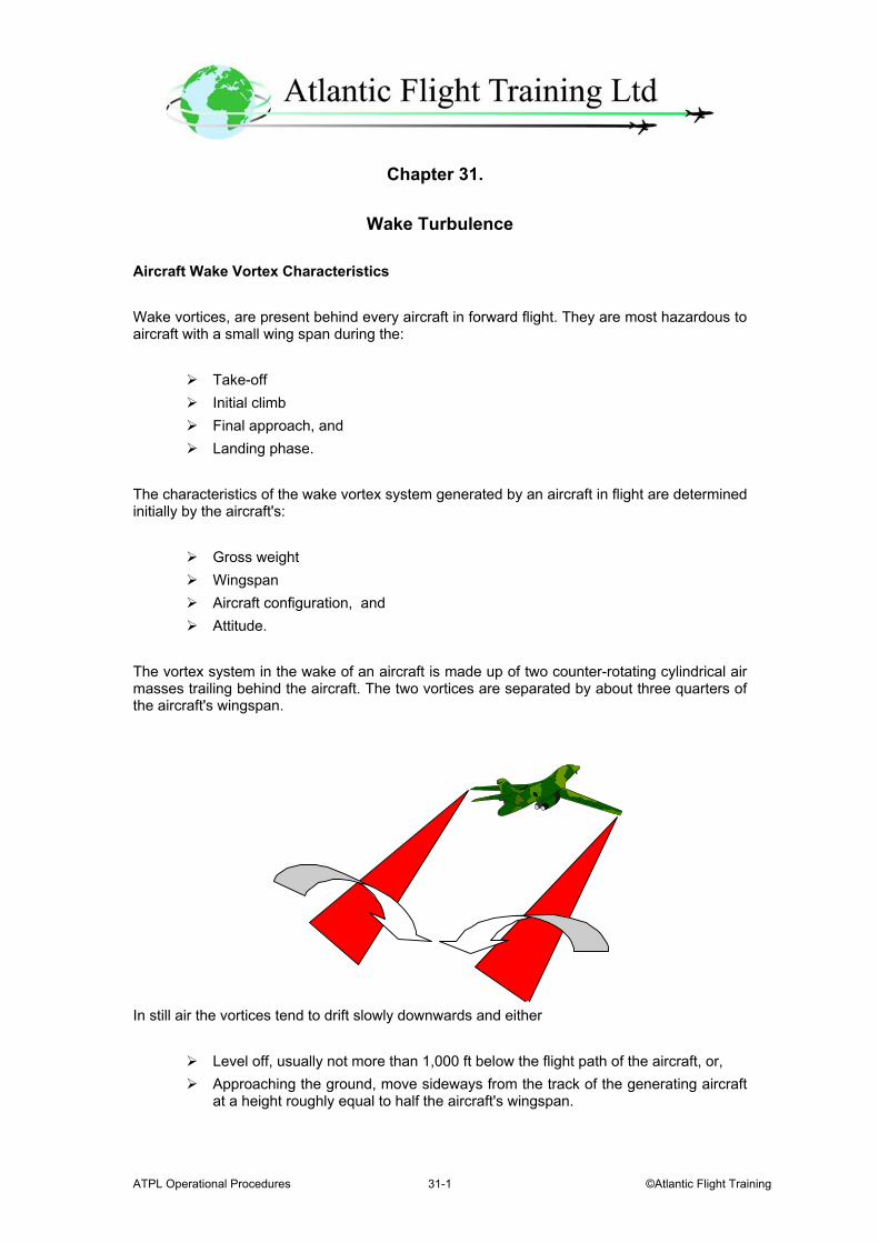
ATPL Operational Procedures ©Atlantic Flight Training 31-1
Chapter 31.
Wake Turbulence Aircraft Wake Vortex Characteristics Wake vortices, are present behind every aircraft in forward flight. They are most hazardous to aircraft with a small wing span during the:
Take-off Initial climb Final approach, and Landing phase.
The characteristics of the wake vortex system generated by an aircraft in flight are determined initially by the aircraft's:
Gross weight Wingspan Aircraft configuration, and Attitude.
The vortex system in the wake of an aircraft is made up of two counter-rotating cylindrical air masses trailing behind the aircraft. The two vortices are separated by about three quarters of the aircraft's wingspan.
In still air the vortices tend to drift slowly downwards and either
Level off, usually not more than 1,000 ft below the flight path of the aircraft, or, Approaching the ground, move sideways from the track of the generating aircraft
at a height roughly equal to half the aircraft's wingspan.
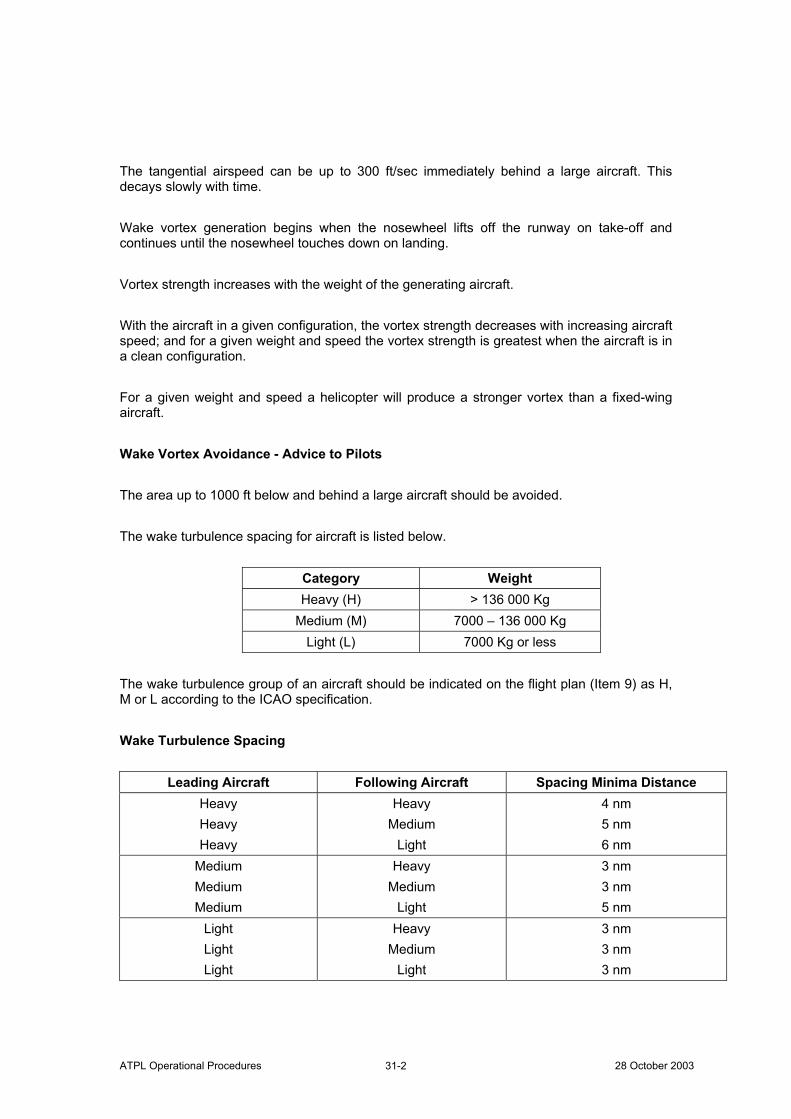
ATPL Operational Procedures 28 October 2003 31-2
The tangential airspeed can be up to 300 ft/sec immediately behind a large aircraft. This decays slowly with time. Wake vortex generation begins when the nosewheel lifts off the runway on take-off and continues until the nosewheel touches down on landing. Vortex strength increases with the weight of the generating aircraft. With the aircraft in a given configuration, the vortex strength decreases with increasing aircraft speed; and for a given weight and speed the vortex strength is greatest when the aircraft is in a clean configuration. For a given weight and speed a helicopter will produce a stronger vortex than a fixed-wing aircraft. Wake Vortex Avoidance - Advice to Pilots The area up to 1000 ft below and behind a large aircraft should be avoided. The wake turbulence spacing for aircraft is listed below.
Category Weight Heavy (H) > 136 000 Kg
Medium (M) 7000 – 136 000 Kg Light (L) 7000 Kg or less
The wake turbulence group of an aircraft should be indicated on the flight plan (Item 9) as H, M or L according to the ICAO specification. Wake Turbulence Spacing
Leading Aircraft Following Aircraft Spacing Minima Distance Heavy Heavy Heavy
Heavy Medium
Light
4 nm 5 nm 6 nm
Medium Medium Medium
Heavy Medium
Light
3 nm 3 nm 5 nm
Light Light Light
Heavy Medium
Light
3 nm 3 nm 3 nm
ATPL Operational Procedures ©Atlantic Flight Training 31-3
The minima should be applied when:
Operating behind another aircraft When crossing the path of an aircraft at the same altitude or 1000 below.
Wake Turbulence Spacing Minima - Departures
Leading Aircraft Following Aircraft Minimum Spacing at the Time Aircraft are Airborne
Heavy Medium or light 2 minutes Medium Light
Departing from the same position 2 minutes
Heavy Medium or light 3 minutes Medium Light
Departing from an intermediate point on
the same runway 3 minutes
Wake Turbulence Spacing Minima - Displaced Landing Threshold A spacing of 2 minutes is used between:
Medium or Light aircraft following a Heavy aircraft, and Light aircraft following a Medium aircraft when operating on a runway with a
displaced threshold when:
A departing Medium or Light aircraft follows a Heavy aircraft or a departing Light aircraft follows a Medium aircraft
An arriving Medium or Light aircraft follows a Heavy aircraft departure, or an arriving Light aircraft follows a departing Medium aircraft:
If the projected flight paths are expected to cross.
Wake Turbulence Spacing Minima - Opposite Direction A spacing of 2 minutes between a Medium or Light aircraft and a Heavy aircraft, and between a Medium aircraft and a Light aircraft whenever the heavier aircraft is making a low or missed approach and the lighter aircraft is:
Taking-off on the same runway in the opposite direction; Landing on the same runway in the opposite direction; Landing on a parallel opposite direction runway separated by less than 760
metres. Wake Turbulence Spacing Minima - Crossing and Parallel Runways When parallel runways separated by less than 760 metres are in use these runways are considered to be a single runway.

ATPL Operational Procedures 28 October 2003 31-4
Wake Turbulence Spacing Minima - Intermediate Approach On intermediate approach a minimum wake turbulence spacing of 5 nm will be applied between a Heavy and a Medium or Light aircraft following or crossing behind.
ATPL Operational Procedures ©Atlantic Flight Training 32-1
Chapter 32.
Windshear Definitions and the Meteorological Background Windshear can be described as a change in wind direction and/or speed in either a vertical or horizontal sense. A simple definition is given by the UK CAA in a still valid AIC.
Definition Variations in vector wind along the aircraft flight path of a pattern, intensity and duration to displace an aircraft abruptly from its intended path such that substantial control action is required.
Low Altitude Windshear Low altitude windshear affects the take-off and landing and can be split into 3 motions
Vertical windshear The change of a horizontal wind vector with height. Horizontal windshear The change of a horizontal wind vector with horizontal distance Updraught/downdraught Changes in the vertical component of wind with horizontal distance.
A windshear encounter can affect large aircraft suddenly by displacing them beyond the pilot’s powers of recovery. Meteorological Features Severe windshear is associated with cumulonimbus or towering cumulus clouds. However, windshear can also be experienced in association with other features such as:
Passage of a front, A marked temperature inversion, A low-level wind maximum A turbulent boundary layer.
Topography or buildings can make the situation worse when there is a strong wind.
ATPL Operational Procedures 28 October 2003 32-2
Thunderstorms This chapter describes the wind flows in and around the thunderstorm which cause the most severe windshears. The shears and draughts associated with the thunderstorm can affect an aircraft from any angle. This makes assessment of angle of attack and the onset of the stall difficult to predict:
Gust Front The Gust Front is a well defined area of cold air flowing out from a downdraught in all directions. This Gust Front leads the storm along its line of movement. The Gust Front will affect the area
Out to 24 to 32 km from the storm centre From the surface up to about 6000 ft.
The area will be subject to turbulence and possibly vertical shear because of the outflowing cold air undercutting inflowing warm air. If the leading edge has no associated precipitation the weather radar will not detect the Gust Front. With some Gust Fronts there is a roll cloud effect which may be associated with the onset of precipitation.
Microbursts A highly concentrated powerful downdraught of air, typically:
Less than 5 km across Lasting from 1 to 5 minutes. Downdraughts up to 60 knots Possible wind speed at the surface of 90 knots
The Microbursts is either “wet or dry”. The dry microburst has no associated precipitation which makes detection difficult. The wet microburst is associated with the precipitation that falls below a cumulonimbus cloud.
Frontal Passage The greatest risk of windshear is from:
Well developed active fronts with a narrow surface frontal zones Marked temperature differences between the two air masses
Sharp changes in wind direction as the front passes will indicate the possibility of windshear, signs to look for are:
A temperature difference of 5° C or more across the frontal zone, and The speed of movement of the front, especially if 30 kt or more,
ATPL Operational Procedures ©Atlantic Flight Training 32-3
The cold front poses the greater risk with the windshear occurring just after the surface passage. The period of windshear for a warm front is longer and precedes the passage. Inversions A strong vertical shear can occur when:
A low level jet forms in association with a strong radiation inversion. These normally develop at night under clear skies.
Low level inversions may develop where a strong upper flow is above a calm flow next to the surface. Windshear can be experienced across the boundary.
Turbulent Boundary Layer In the boundary layer:
Strong surface winds are associated with large gusts and lulls causing horizontal windshear
Solar heating of the ground causes up and downdraughts. Topographical windshears Natural or man made features affect the wind flow and can cause windshear. The direction of flow and wind speed determine the severity of the windshear, Mountain Waves being the best example. The Effects of Windshear on an Aircraft in Flight In windshear the magnitude of the change of wind vector and the rate at which it happens determine the severity. An aeroplane at 1000 ft agl has a headwind component of 40 kt with a surface of 20 kt on the runway. The 20 kt difference may:
Reduce evenly and the effect will be negligible, or If the speed differential still exists at 300 ft the change is going to be marked.
Windshear implies a narrow borderline and the 20 kt of wind speed may well be lost over a small vertical distance.
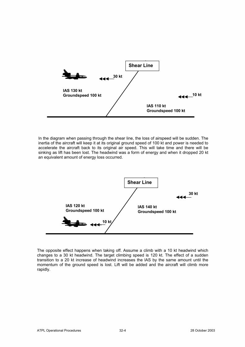
ATPL Operational Procedures 28 October 2003 32-4
Shear Line
IAS 130 kt Groundspeed 100 kt
IAS 110 kt Groundspeed 100 kt
30 kt
10 kt
In the diagram when passing through the shear line, the loss of airspeed will be sudden. The inertia of the aircraft will keep it at its original ground speed of 100 kt and power is needed to accelerate the aircraft back to its original air speed. This will take time and there will be sinking as lift has been lost. The headwind was a form of energy and when it dropped 20 kt an equivalent amount of energy loss occurred.
Shear Line
IAS 140 kt Groundspeed 100 kt
IAS 120 kt Groundspeed 100 kt
30 kt
10 kt
The opposite effect happens when taking off. Assume a climb with a 10 kt headwind which changes to a 30 kt headwind. The target climbing speed is 120 kt. The effect of a sudden transition to a 20 kt increase of headwind increases the lAS by the same amount until the momentum of the ground speed is lost. Lift will be added and the aircraft will climb more rapidly.
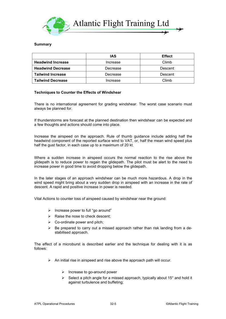
ATPL Operational Procedures ©Atlantic Flight Training 32-5
Summary IAS Effect Headwind Increase Increase Climb Headwind Decrease Decrease Descent Tailwind Increase Decrease Descent Tailwind Decrease Increase Climb Techniques to Counter the Effects of Windshear There is no international agreement for grading windshear. The worst case scenario must always be planned for. If thunderstorms are forecast at the planned destination then windshear can be expected and a few thoughts and actions should come into place. Increase the airspeed on the approach. Rule of thumb guidance include adding half the headwind component of the reported surface wind to VAT, or, half the mean wind speed plus half the gust factor, in each case up to a maximum of 20 kt.
Where a sudden increase in airspeed occurs the normal reaction to the rise above the glidepath is to reduce power to regain the glidepath. The pilot must be alert to the need to increase power in good time to avoid dropping below the glidepath. In the later stages of an approach windshear can be much more hazardous. A drop in the wind speed might bring about a very sudden drop in airspeed with an increase in the rate of descent. A rapid and positive increase in power is needed. Vital Actions to counter loss of airspeed caused by windshear near the ground:
Increase power to full “go around” Raise the nose to check descent; Co-ordinate power and pitch; Be prepared to carry out a missed approach rather than risk landing from a de-
stabilised approach. The effect of a microburst is described earlier and the technique for dealing with it is as follows:
An initial rise in airspeed and rise above the approach path will occur.
Increase to go-around power Select a pitch angle for a missed approach, typically about 15° and hold it
against turbulence and buffeting;
ATPL Operational Procedures 28 October 2003 32-6
The increased airspeed and rate of climb may be rapidly lost. If the downdraught
strikes, airspeed may be lost and the aircraft may start to descend even with the high power and pitch angle.
Where the downdraught begins to change to increasing tailwind is the most critical period. The rate of descent may reduce, but the airspeed may still continue to fall.
If maximum thrust is already applied and there is a risk of striking the ground or an obstacle. Increase the pitch angle until the stick shaker is felt.
When there is an indefinite risk of windshear, it may be possible to use a longer runway, or one that points away from an area of potential threat. Rotating at a slightly higher speed may be possible. The high power setting and high pitch angle after rotation put the aircraft an optimum configuration should a microburst strike. In both approach and take-off cases.
Vital Actions are:
Use the maximum power available as soon as possible; Adopt a pitch angle of around 15° and try and hold that attitude. Do not
chase airspeed; Be guided by stick shaker indications when holding or increasing pitch
attitude, easing the back pressure as required to attain and hold a slightly lower attitude.
Windshear warning can be provided in several ways:
Meteorological warning; ATS warning; Pilot warning; On board pre-encounter warning; On board encounter warning and/or guidance.