Embed Size (px)
Citation preview

Atomic Layer Deposition-Derived Ultra-Low-Density Composite BulkMaterials with Deterministic Density and CompositionMonika M. Biener,* Juergen Biener, Yinmin M. Wang, Swanee J. Shin, Ich C. Tran, Trevor M. Willey,Frederic N. Perez, Jon F. Poco, Stuart A. Gammon, Kevin B. Fournier, Anthony W. van Buuren,Joe H. Satcher, Jr., and Alex V. Hamza
Nanoscale Synthesis and Characterization Laboratory, Lawrence Livermore National Laboratory, 7000 East Avenue, Livermore,California 94550, United States
*S Supporting Information
ABSTRACT: A universal approach for on-demand develop-ment of monolithic metal oxide composite bulk materials withair-like densities (<5 mg/cm3) is reported. The materials arefabricated by atomic layer deposition of titania (TiO2) or zincoxide (ZnO) using the nanoscale architecture of 1 mg/cm3
SiO2 aerogels formed by self-organization as a blueprint. Thisapproach provides deterministic control over density andcomposition without affecting the nanoscale architecture of thecomposite material that is otherwise very difficult to achieve.We found that these materials provide laser-to-X-rayconversion efficiencies of up to 5.3%, which is the highestconversion efficiency yet obtained from any foam-based target, thus opening the door to a new generation of highly efficientlaser-induced nanosecond scale multi-keV X-ray sources.
KEYWORDS: ultra-low-density foam, aerogels, atomic layer deposition, core−shell composite material, titanium dioxide, zinc oxide,lasers, X-ray source
■ INTRODUCTION
Monolithic porous bulk materials with air-like densities haverecently attracted renewed interest1−5 because of manyemerging applications in catalysis, energy storage andconversion, thermal insulation, shock energy absorption, andhigh-energy density physics.6−11 The longest known low-density bulk materials are aerogels12 whose self-similar, fractalnetwork structure is formed by cross-linking colloidal nano-particles,13 but despite the tremendous progress that has beenmade since their discovery more than 80 years ago,12,14 therealization of ultra-low-density aerogels with densities of <5mg/cm3 remains extremly challenging. The difficulty is thatreducing the density often results in unpredictable changes inthe morphology or even collapse of the structure as both thestiffness and strength of porous materials decrease at a morethan linear rate as the density decreases, typically following aquadratic or stronger scaling relationship.15 An exception is theespecially robust SiO2 sol−gel system that allows fabrication ofhigh-quality bulk samples with densities that are lower than thatof the air that fills their pores (1.2 mg/cm3 at 760 Torr and 20°C),15 and although other recently developed synthesisapproaches are capable of generating <5 mg/cm3 bulkmaterials, they are either limited to carbon with graphene asthe structural building block1,2 or restricted to micrometer-sizedfeatures.4
Here, we report on rapid, on-demand development ofmonolithic, ultra-low-density (<5 mg/cm3), mid-to-high-atomicnumber (Z) composite bulk materials with deterministiccontrol over density and composition. Although our work ismotivated by the needs of the Lawrence Livermore NationalLaboratory to develop brighter, nanosecond scale X-ray (∼5−10 keV) sources obtained by laser-irradiating high-Z materials,ultra-low-density monolithic porous bulk materials have manyother promising applications. Laser-induced nanosecond X-raysources can be used, for example, to obtain radiographs fromimploding inertial fusion capsules. A promising approach toincreasing the brightness of laser-created X-ray sources is toreplace the traditional metallic foil targets by an ultra-low-density high-Z foam material.10 The idea is to increase the laser-to-X-ray conversion efficiency by volumetric heating of thetarget material, which requires that the laser irradiationpenetrates through the entire volume of a millimeter-sizedtarget. This requirement limits the foam density to below ∼7mg/cm3 because below this density a laser heating wavepropagates supersonically through the material,16 forming aplasma without hydrodynamic motion of the target materialand thus producing a flat density profile with negligible density
Received: September 24, 2013Accepted: November 27, 2013Published: November 27, 2013
Research Article
www.acsami.org
© 2013 American Chemical Society 13129 dx.doi.org/10.1021/am4041543 | ACS Appl. Mater. Interfaces 2013, 5, 13129−13134
gradients and flow velocities. Above this density, the laserdeposits its energy locally over a small spatial scale and theenergy goes into bulk hydrodynamic motion of the ablatedmaterial rather than heating the target material. Further, in theablated material, laser light is scattered by laser-driveninstabilities17 (Raman scattering, Brillouin scattering, andfilamentation) and is unavailable to then heat the target.Other requirements are that the solid should ideally beuniformly distributed on the length scale of the laser light,thus eliminating engineered microlattices4 as possible tem-plates, and that the high-Z atomic fraction should be as high aspossible to achieve high conversion efficiencies, whicheliminates the use of higher-density templates. The uniformityof laser heating is important as it creates a homogeneous X-raysource that provides higher-quality radiographs than an X-raybacklighter with gradients in either the source strength (i.e.,surface brightness) or the spectral content.18,19
Here, we use recently developed high-quality 1 mg/cm3 SiO2aerogel bulk samples15 as robust nanoscale scaffolds that can behomogeneously coated to the desired density and compositionusing atomic layer deposition (ALD). As previously demon-strated, ALD is ideally suited to uniformly coat ultra-high-aspect ratio materials with atomic scale thickness control,20−24
thus providing the desired deterministic control over densityand composition. The atomic scale control over film thicknessprovided by ALD is the result of using a suitable pair ofsequential, self-limiting surface reactions to deposit a desiredmaterial.25 The concept of fabricating monolithic metal oxidecomposite bulk materials with air-like densities by ALD coatingof 1 mg/cm3 SiO2 aerogel bulk samples was tested for TiO2 andZnO but can be easily extended to other ALD processes orcombinations thereof that use sufficiently volatile precursorspecies. We find that our approach results in doping (Ti)concentrations much higher than those of previous attempts tofabricate TiO2-doped silica aerogels by copolymerization offixed ratios of tetramethoxysilane (TMOS) and titanium(IV)ethoxide monomers.26
■ RESULTS AND DISCUSSIONOptical images from 1 mg/cm3 SiO2 aerogels before and afterbeing coated with TiO2 and ZnO ALD are shown in Figure 1
and Figure 1 of the Supporting Information, respectively. Whilethe uncoated SiO2 aerogels are practically invisible under whitelight illumination, the material turns increasingly opaque withan increasing number of ALD cycles (Figure 1 of theSupporting Information). The material seems to be homoge-neously coated as revealed by optical inspection.Both composition and uniformity were studied by Ruth-
erford backscattering spectrometry (RBS), and representativedata obtained from metal oxide-coated SiO2 scaffold materials(MO−SiO2) are shown in Figure 2a together with depth
profiles of the atomic fractions of Ti and Zn (Figure 2b).RUMP code simulations (Figure 2a,b, solid lines) confirm thatthe material homogeneously coated the RBS detection depth(500 μm). For the example shown in Figure 2a, the atomicfractions of Ti (30 cycles) and Zn (eight cycles) are ∼19 and23%, respectively, and do not change with depth. The atomic
Figure 1. Optical image of 1 mg/cm3 SiO2 aerogels before (left) andafter (right) being coated with 30 cycles of TiO2 ALD. The uncoatedSiO2 aerogel is practically invisible but turns increasingly opaque withan increasing number of ALD cycles.
Figure 2. Composition and depth uniformity of ALD-coated SiO2scaffolds. (a) RBS spectra of TiO2-coated (30 cycles) and ZnO-coated(eight cycles) 1 mg/cm3 SiO2 scaffolds. The positions of the surfacepeaks of O, Si, Ti, and Zn are denoted. Solid lines are the result ofRUMP simulations. (b) Depth profiles of the Ti and Znconcentrations extracted from these RBS spectra. (c) Density vsnumber of ALD cycles for both TiO2- and ZnO-coated SiO2 scaffoldscalculated form RBS composition data.
ACS Applied Materials & Interfaces Research Article
dx.doi.org/10.1021/am4041543 | ACS Appl. Mater. Interfaces 2013, 5, 13129−1313413130
composition provided by RUMP code simulations was alsoused to calculate the density of the MO−SiO2 compositematerials (Figure 2c). For TiO2, the density of the compositematerial increases approximately linearly with the number ofALD cycles at a rate of ∼0.05 mg/cm3 per TiO2 ALD cycle(Figure 2c). For ZnO, the density increases up to 20-fold faster(up to ∼1 mg/cm3 per cycle). The high growth rate observedfor the ZnO ALD process on the SiO2 scaffold suggests a non-ideal ALD behavior as the growth rates for TiO2 and ZnOreported in the literature differ by a factor of only ∼2.5 (0.19nm for ZnO27 vs 0.078 nm for TiO2
28). Note, however, that thenon-ideal behavior of the ZnO ALD process does not affect thecompositional uniformity of the ZnO−SiO2 composite material(Figure 2b). The ZnO ALD process also seems to have anucleation-related induction period as the density increases at a4-fold slower rate during the first eight cycles (∼0.25 mg percycle, which is still 5 times the TiO2 ALD growth rate). Verysimilar results were obtained by weight measurements, althoughwith larger error bars because of the extremely small samplemass (1−5 mg).The nanoscale morphology of the SiO2 scaffold as well as of
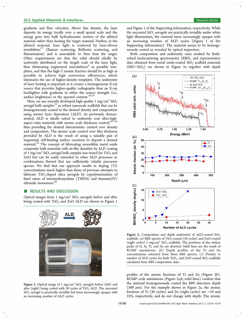
the coated composite materials is illustrated by the transmissionelectron microscopy (TEM) images shown in Figure 3 and
Figure 2 of the Supporting Information, respectively. The SiO2aerogel (Figure 3a) and the coated materials (Figure 3b,c) havevery similar nanoscale morphologies that consist of ∼10 nmwide ligaments. The deposited TiO2 is not readily distinguish-able from the underlying SiO2 scaffold because both the SiO2ligaments and the deposited TiO2
29 are amorphous, and theiratomic numbers are similar, thus providing little contrast.Nevertheless, the fact that the formation of larger TiO2 particlesis not observed implies that the coating is conformal and
uniform. The uniformity of the TiO2 coating is furthersubstantiated by selected-area TEM−EDX analysis as the Ti/Si ratio was found to be nearly independent of the size of theanalyzed area. By contrast, individual crystalline ZnO nano-particles seem to decorate the ZnO-coated SiO2 scaffold(Figure 3c,d). The observation of individual crystalline ZnOnanoparticles [can be indexed to wurtzite phase (see the insetselected area diffraction pattern of Figure 3d)] is consistentwith the idea of a low nucleation density suggested by theobservation of an induction period (Figure 2b).The nanoscale morphology of the MO−SiO2 composite
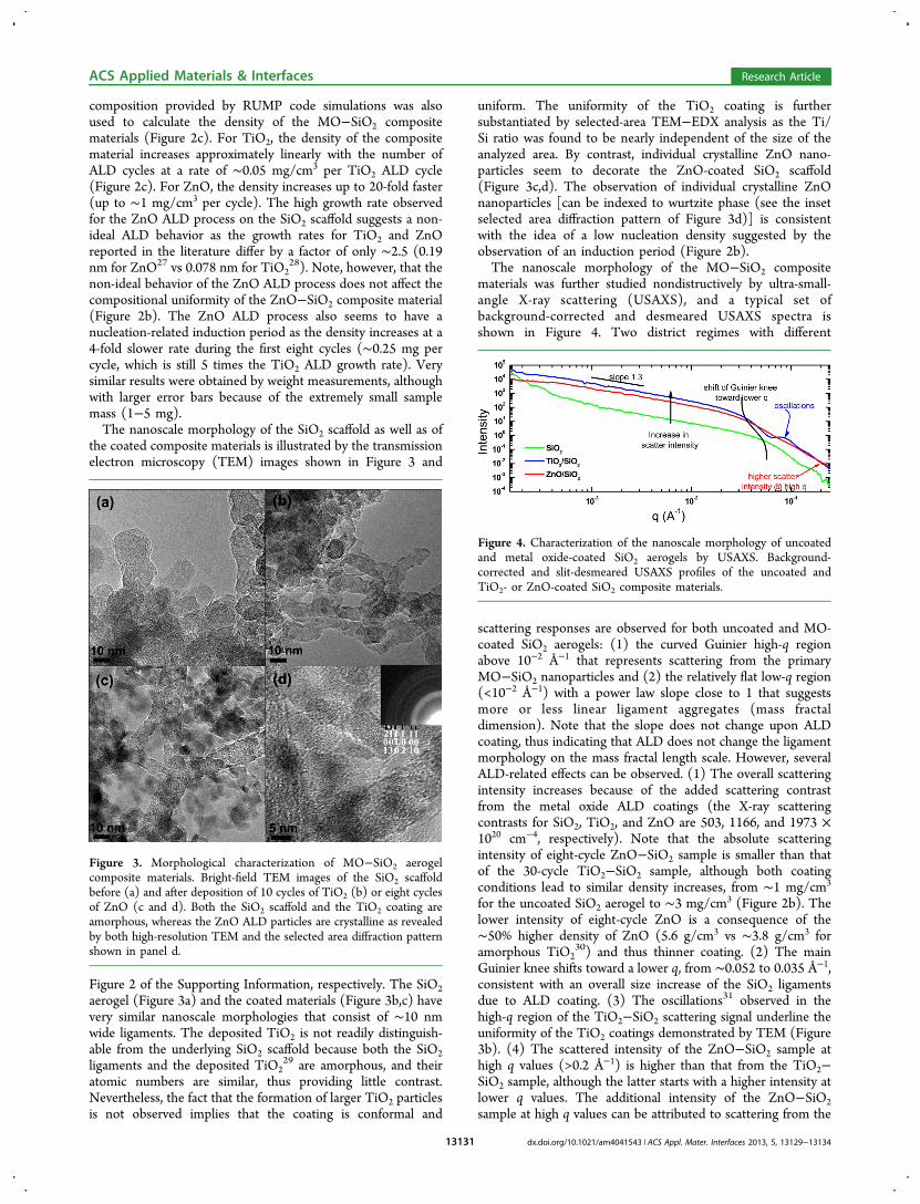
materials was further studied nondistructively by ultra-small-angle X-ray scattering (USAXS), and a typical set ofbackground-corrected and desmeared USAXS spectra isshown in Figure 4. Two district regimes with different
scattering responses are observed for both uncoated and MO-coated SiO2 aerogels: (1) the curved Guinier high-q regionabove 10−2 Å−1 that represents scattering from the primaryMO−SiO2 nanoparticles and (2) the relatively flat low-q region(<10−2 Å−1) with a power law slope close to 1 that suggestsmore or less linear ligament aggregates (mass fractaldimension). Note that the slope does not change upon ALDcoating, thus indicating that ALD does not change the ligamentmorphology on the mass fractal length scale. However, severalALD-related effects can be observed. (1) The overall scatteringintensity increases because of the added scattering contrastfrom the metal oxide ALD coatings (the X-ray scatteringcontrasts for SiO2, TiO2, and ZnO are 503, 1166, and 1973 ×1020 cm−4, respectively). Note that the absolute scatteringintensity of eight-cycle ZnO−SiO2 sample is smaller than thatof the 30-cycle TiO2−SiO2 sample, although both coatingconditions lead to similar density increases, from ∼1 mg/cm3
for the uncoated SiO2 aerogel to ∼3 mg/cm3 (Figure 2b). Thelower intensity of eight-cycle ZnO is a consequence of the∼50% higher density of ZnO (5.6 g/cm3 vs ∼3.8 g/cm3 foramorphous TiO2
30) and thus thinner coating. (2) The mainGuinier knee shifts toward a lower q, from ∼0.052 to 0.035 Å−1,consistent with an overall size increase of the SiO2 ligamentsdue to ALD coating. (3) The oscillations31 observed in thehigh-q region of the TiO2−SiO2 scattering signal underline theuniformity of the TiO2 coatings demonstrated by TEM (Figure3b). (4) The scattered intensity of the ZnO−SiO2 sample athigh q values (>0.2 Å−1) is higher than that from the TiO2−SiO2 sample, although the latter starts with a higher intensity atlower q values. The additional intensity of the ZnO−SiO2sample at high q values can be attributed to scattering from the
Figure 3. Morphological characterization of MO−SiO2 aerogelcomposite materials. Bright-field TEM images of the SiO2 scaffoldbefore (a) and after deposition of 10 cycles of TiO2 (b) or eight cyclesof ZnO (c and d). Both the SiO2 scaffold and the TiO2 coating areamorphous, whereas the ZnO ALD particles are crystalline as revealedby both high-resolution TEM and the selected area diffraction patternshown in panel d.
Figure 4. Characterization of the nanoscale morphology of uncoatedand metal oxide-coated SiO2 aerogels by USAXS. Background-corrected and slit-desmeared USAXS profiles of the uncoated andTiO2- or ZnO-coated SiO2 composite materials.
ACS Applied Materials & Interfaces Research Article
dx.doi.org/10.1021/am4041543 | ACS Appl. Mater. Interfaces 2013, 5, 13129−1313413131

crystalline ZnO nanoparticles, as detected by TEM (Figure 3c).In an attempt to extract more detailed structural information,the experimental USAXS profiles of the MO−SiO2 sampleswere least-squares fit using a core−shell scattering model.Details regarding the fitting procedure can be found in theSupporting Information.In short, the analysis confirms the overall network
morphology observed by TEM as both uncoated and metaloxide-coated SiO2 particles have USAXS-derived particlediameters of ∼8−9 nm (Figure 3 of the SupportingInformation). The coating thickness derived by USAXS is∼2.8 and 0.26 nm for TiO2 (30 cycles) and ZnO ALD (eightcycles), respectively. In the case of TiO2, the USAXS-derivedcoating thickness is in excellent agreement with the expectedlayer thickness of a 30-cycle TiO2 ALD coating (30 × 0.078nm/cycle = 2.34 nm). The USAXS-derived ZnO coatingthickness, however, is much lower than expected from the RBS-derived mass gain, thus demonstrating that the core−shellmodel is not suitable for describing the morphology of theZnO−SiO2 material as expected from the observation ofcrystalline ZnO nanoparticles in TEM micrographs (Figure3d). The analysis also reveals that both the uncoated SiO2 andthe TiO2-coated SiO2 aerogels have narrow size distributionscentered around 8−9 nm (Figure 3 of the SupportingInformation).Finally, we tested the performance of the MO−SiO2
composite materials as multi-keV X-ray sources at the Omegalaser facility32 (Laboratory for Laser Energetics, University ofRochester, Rochester, NY). All targets were irradiated by 40laser beams for a total of 20 kJ on target at a wavelength of 351nm.26 The experiments revealed that the MO−SiO2 compositematerials discussed above have very high laser-to-X-rayconversion efficiencies (CEs). A photograph of such a low-density TiO2−SiO2 composite foam target (2 mg/cm3 TiO2and 1 mg/cm3 SiO2, ∼20 atom % Ti) is presented in Figure 5a,and a schematic of the laser beam configuration is shown inFigure 5b. Snapshot images of ∼4.7 keV X-ray emission atdifferent times during laser irradiation, displayed in Figure 5c,show uniform emission throughout the whole volume,
indicating penetration of the laser through the whole foammaterial. Absolute measurements of the X-ray output revealthat TiO2−SiO2 composite foam targets with 20 atom % Tihave a laser-to-X-ray CE of 5.3% in an energy band from 4.5 to6.0 keV. This appears much higher than the CE valuesmeasured on lower-Ti concentration foam targets (CE of 0.8%for 4 atom % Ti) during the same experiment and exceeds theperformance of thick-foil targets (CE of 3%).33,34 This isactually the highest CE yet obtained from any foam-basedtarget. High-concentration Zn foams were also tested in thesame configuration. They showed a CE of 1% in the band from9 to 11 keV, which is the highest yet reported from a Znmaterial. Overall, the high CE of the MO−SiO2 compositefoam targets described here will open the door to newapplications of laser-induced X-ray generation. The possibilityto easily adjust composition and density greatly facilitates theoptimization of these targets.
■ CONCLUSIONSThe ALD-based approach described here provides a pathtoward the development of ultra-low-density foam materialswith deterministic control over density and composition.Compared to traditional sol−gel-based foam development,the ALD approach described here not only drastically reducedthe developing time but also provided better performingmaterials for the laser-induced X-ray source application. TheALD approach is universal and can easily be expanded to evenmore complex ternary or quaternary materials by combiningdifferent ALD processes. We expect this to have far-reachingimplications in the fields of catalysis and sensor applications.Beyond the synthesis of new functional materials, ALD alsoprovides an opportunity to further characterize ultra-low-density materials that are often very difficult to assess bytraditional characterization methods because of the lack ofcontrast or mechanical instability. For example, the ALD-induced mass gain can also be used to calculate the specificsurface area of ultra-low-density foam materials that otherwisecannot be assessed by BET measurements because ofdeformation or collapse of the structure during wetting withcryogenic N2. For the 1 mg/cm3 SiO2 aerogels used in thisstudy, the observed mass gain of ∼0.05 mg/cm3 per TiO2 ALDcycle translates into a calculated surface area of ∼200 m2/g(assuming a growth rate of 0.078 nm TiO2 per cycle
28). This isclose to the surface area of 207 m2/g of a hypothetical materialthat consists of 13 nm diameter spherical particles ofamorphous SiO2 (density of ∼2.2 g/cm), thus validating theapproach to estimating the surface area of ultra-low-densitymaterials from the experimentally observed ALD-inducedweight gain.
■ EXPERIMENTAL SECTIONSynthesis of Materials. SiO2 aerogels with a density of ∼1 mg/
cm3 were prepared as described previously15 using a two-step sol−gelchemistry approach and the high-temperature fast-reactor solventextraction method developed by Poco and co-workers.35 The details ofaerogel synthesis can be found in ref 15. The aerogels were cast ineither cubic glass molds (volume of 1 cm3) or, for laser experiments, in2 mm diameter polyimide tubes (C22H10N2O5, 50 μm wall thicknessand 2 mm length). The uncoated aerogels were monolithic andpractically invisible under white light illumination. The target densityof the uncoated SiO2 aerogels (1 mg/cm3) was confirmed bymeasuring the mass of samples that were cast in 1 cm3 molds. TheSiO2 aerogel was then converted to a material with the desiredcomposition and density (for this application, <5 mg/cm3) by being
Figure 5. Multi-kiloelectronvolt laser-induced X-ray sources forradiography. (a) Schematics and photograph of a cylindrical low-density foam target. (b) Schematic of the laser beam configuration ofthe Omega laser for X-ray source experiments. (c) Snapshots of ∼4.7keV X-ray emission from a 2 mg/cm3 TiO2−1 mg/cm3 SiO2composite target at different times during the laser irradiationdemonstrating volumetric X-ray generation.
ACS Applied Materials & Interfaces Research Article
dx.doi.org/10.1021/am4041543 | ACS Appl. Mater. Interfaces 2013, 5, 13129−1313413132

coated with 2−30 cycles of either a titanium tetrachloride (TiCl4/H2O)
28 or diethyl zinc (ZnEt2/H2O) ALD process23 using a warmwall reactor (wall and stage temperature of 110 °C). To facilitatehandling, the aerogels were kept in their molds during coating. Longpump (20 s), pulse (500 s at ∼133 Pa), and nitrogen purge cycles (500s) were used to ensure uniform coatings throughout the porousmaterial.Characterization of Materials. The composition and depth
uniformity were measured by Rutherford backscattering spectrometry(RBS, 2.0 MeV 4He+ ions, scattering angle of 164o) and RUMP codesimulations.36 Multiple scattering events are not expected to affect theresults of our RUMP code simulations because their contribution is sosmall in absolute value, especially at the higher-energy side where wedetermine the composition. The mass gain of the coated samples wascalculated from the composition determined by RBS as direct weightmeasurements resulted in larger error bars. The nanoscale morphologyof the ligaments of the aerogel was characterized by bright fieldtransmission electron microscopy (BF-TEM), and the overallmorphology of the material (size, shape, and distribution of thestructural elements) was assessed by USAXS using the Bonse-Hartdouble-crystal USAXS instrument on beamline 15ID-D at theAdvanced Photon Source (Argonne National Laboratory, Argonne,IL).37,38 For each sample, slit-smeared one-dimensional data werecollected in transmission mode by using a photon beam energy of 17.0kV (λ = 0.72932 Å), covering a scattering angular range (q vector)from 10−4 to 0.3 Å−1. The raw data were corrected for backgroundusing the small-angle scattering profile of air as a reference sample.Irena and Indra31 (available online at http://usaxs.xor.aps.anl.gov)were employed to correct and desmear the USAXS data. The slit-desmeared data for uncoated SiO2 aerogels were then least-squares fitusing log-normal distributions of scatterers, having a form factor ofspheroids. For TiO2- and ZnO-coated SiO2 aerogels, a core−shellmodel of scatterers was used.Laser-Induced Nanosecond Scale Multi-Kiloelectronvolt X-
ray Generation. The performance of the MO−SiO2 compositematerials as multi-kiloelectronvolt X-ray sources was tested at theOmega laser facility32 (Laboratory for Laser Energetics, University ofRochester). All targets were irradiated by 40 laser beams for a total of20 kJ on target at a wavelength of 351 nm.
■ ASSOCIATED CONTENT*S Supporting InformationAdditional information about the characterization of materials.This material is available free of charge via the Internet athttp://pubs.acs.org.
■ AUTHOR INFORMATIONCorresponding Author*E-mail: [email protected] authors declare no competing financial interest.
■ ACKNOWLEDGMENTSWork at Lawrence Livermore National Laboratory (LLNL) wasperformed under the auspices of the U.S. Department ofEnergy by LLNL under Contract DE-AC52-07NA27344.Project 13-LWD-031 was funded by the LDRD Program atLLNL. ChemMatCARS is supported by NSF and DOE undergrant NSF/CHE-0822838. APS is supported by the DOE BES,under contract DE-AC02-06CH11357.
■ REFERENCES(1) Mecklenburg, M.; Schuchardt, A.; Mishra, Y. K.; Kaps, S.;Adelung, R.; Lotnyk, A.; Kienle, L.; Schulte, K. Adv. Mater. 2012, 24,3486−3490.(2) Qiu, L.; Liu, J. Z.; Chang, S. L. Y.; Wu, Y.; Li, D. Nat. Commun.2012, 3, 1241.
(3) Zhao, Y.; Hu, C. G.; Hu, Y.; Cheng, H. H.; Shi, G. Q.; Qu, L. T.Angew. Chem., Int. Ed. 2012, 51, 11371−11375.(4) Schaedler, T. A.; Jacobsen, A. J.; Torrents, A.; Sorensen, A. E.;Lian, J.; Greer, J. R.; Valdevit, L.; Carter, W. B. Science 2011, 334,962−965.(5) Biener, J.; Stadermann, M.; Suss, M.; Worsley, M. A.; Biener, M.M.; Rose, K. A.; Baumann, T. F. Energy Environ. Sci. 2011, 4, 656−667.(6) Gesser, H. D.; Goswami, P. C. Chem. Rev. 1989, 89, 765−788.(7) Gibson, L. J.; Ashby, M. F. Cellular solids: Structure and properties,2nd ed.; Cambridge University Press: Cambridge, U.K., 1997.(8) Fournier, K. B.; Constantin, C.; Poco, J.; Miller, M. C.; Back, C.A.; Suter, L. J.; Satcher, J.; Davis, J.; Grun, J. Phys. Rev. Lett. 2004, 92,165005.(9) Fournier, K. B.; Satcher, J. H.; May, M. J.; Poco, J. F.; Sorce, C.M.; Colvin, J. D.; Hansen, S. B.; MacLaren, S. A.; Moon, S. J.; Davis, J.F.; Girard, F.; Villette, B.; Primout, M.; Babonneau, D.; Coverdale, C.A.; Beutler, D. E. Phys. Plasmas 2009, 16, 052703.(10) Perez, F.; Kay, J. J.; Patterson, J. R.; Kane, J.; Villette, B.; Girard,F.; Reverdin, C.; May, M.; Emig, J.; Sorce, C.; Colvin, J.; Gammon, S.;Jaquez, J.; Satcher, J. H.; Fournier, K. B. Phys. Plasmas 2012, 19,083101.(11) Kucheyev, S. O.; Hamza, A. V. J. Appl. Phys. 2010, 108.(12) Kistler, S. S. Nature 1931, 127, 741−741.(13) Vacher, R.; Woignier, T.; Pelous, J.; Courtens, E. Phys. Rev. B1988, 37, 6500.(14) Huesing, N.; Schubert, U. Angew. Chem., Int. Ed. 1998, 37, 23−45.(15) Kucheyev, S. O.; Stadermann, M.; Shin, S. J.; Satcher, J. H.;Gammon, S. A.; Letts, S. A.; van Buuren, T.; Hamza, A. V. Adv. Mater.2012, 24, 776−780.(16) Denavit, J.; Phillion, D. W. Phys. Plasmas 1994, 1, 1971−1984.(17) Kruer, W. L. The Physics of Laser Plasma Interactions; WestviewPress: Boulder, CO, 2003.(18) Landen, O. L.; Farley, D. R.; Glendinning, S. G.; Logory, L. M.;Bell, P. M.; Koch, J. A.; Lee, F. D.; Bradley, D. K.; Kalantar, D. H.;Back, C. A.; Turner, R. E. Rev. Sci. Instrum. 2001, 72, 627−634.(19) Workman, J.; Fincke, J. R.; Keiter, P.; Kyrala, G. A.; Pierce, T.;Sublett, S.; Knauer, J. P.; Robey, H.; Blue, B.; Glendinning, S. G.;Landen, O. L. Rev. Sci. Instrum. 2004, 75, 3915−3920.(20) Baumann, T. F.; Biener, J.; Wang, Y. M. M.; Kucheyev, S. O.;Nelson, E. J.; Satcher, J. H.; Elam, J. W.; Pellin, M. J.; Hamza, A. V.Chem. Mater. 2006, 18, 6106−6108.(21) Biener, J.; Baumann, T. F.; Wang, Y. M.; Nelson, E. J.;Kucheyev, S. O.; Hamza, A. V.; Kemell, M.; Ritala, M.; Leskela, M.Nanotechnology 2007, 18, 055303.(22) George, S. M. Chem. Rev. 2010, 110, 111−131.(23) Kucheyev, S. O.; Biener, J.; Wang, Y. M.; Baumann, T. F.; Wu,K. J.; van Buuren, T.; Hamza, A. V.; Satcher, J. H.; Elam, J. W.; Pellin,M. J. Appl. Phys. Lett. 2005, 86, 083108.(24) Elam, J. W.; Xiong, G.; Han, C. Y.; Wang, H. H.; Birrell, J. P.;Welp, U.; Hryn, J. N.; Pellin, M. J.; Baumann, T. F.; Poco, J. F.;Satcher, J. H. J. Nanomater. 2006, 2006, 64501.(25) Leskela, M.; Ritala, M. Angew. Chem., Int. Ed. 2003, 42, 5548−5554.(26) Perez, F.; Patterson, J. R.; May, M.; Colvin, J. D.; Biener, M. M.;Wittstock, A.; Kucheyev, S. O.; Charnvanichborikarn, S.; Satcher, J. H.;Gammon, S. A.; Poco, J. F.; Fujioka, S.; Zhang, Z.; Ishihara, K.;Tanaka, N.; Ikenouchi, T.; Nishimura; Fournier, K. B. Phys. Plasmas2014, to be submitted for publication.(27) Keun Kim, S.; Seong Hwang, C.; Ko Park, S.-H.; Jin Yun, S.Thin Solid Films 2005, 478, 103−108.(28) Aarik, J.; Aidla, A.; Mandar, H.; Uustare, T. Appl. Surf. Sci. 2001,172, 148−158.(29) Biener, M. M.; Biener, J.; Wichmann, A.; Wittstock, A.;Baumann, T. F.; Baeumer, M.; Hamza, A. V. Nano Lett. 2011, 11,3085−3090.(30) Hoang, V. V. Nanotechnology 2008, 19, 105706.(31) Ilavsky, J.; Jemian, P. R. J. Appl. Crystallogr. 2009, 42, 347−353.
ACS Applied Materials & Interfaces Research Article
dx.doi.org/10.1021/am4041543 | ACS Appl. Mater. Interfaces 2013, 5, 13129−1313413133

(32) Boehly, T. R.; Brown, D. L.; Craxton, R. S.; Keck, R. L.; Knauer,J. P.; Kelly, J. H.; Kessler, T. J.; Kumpan, S. A.; Loucks, S. J.; Letzring,S. A.; Marshall, F. J.; McCrory, R. L.; Morse, S. F. B.; Seka, W.; Soures,J. M.; Verdon, C. P. Opt. Commun. 1997, 133, 495−506.(33) Girard, F.; Primout, M.; Villette, B.; Stemmler, P.; Jacquet, L.;Babonneau, D.; Fournier, K. B. Phys. Plasmas 2009, 16, 052704.(34) Girard, F.; Primout, M.; Villette, B.; Stemmler, P.; Jacquet, L.;Babonneau, D.; Fournier, K. B. Phys. Plasmas 2011, 18, 079901.(35) Poco, J. F.; Coronado, P. R.; Pekala, R. W.; Hrubesh, L. W.Mater. Res. Soc. Symp. Proc. 1996, 431, 297−302.(36) Doolittle, L. R. Nucl. Instrum. Methods Phys. Res., Sect. B 1985, 9,344−351.(37) Ilavsky, J.; Jemian, P. R.; Allen, A. J.; Zhang, F.; Levine, L. E.;Long, G. G. J. Appl. Crystallogr. 2009, 42, 469−479.(38) Ilavsky, J.; Zhang, F.; Allen, A. J.; Levine, L. E.; Jemian, P. R.;Long, G. G. Metall. Mater. Trans. A 2013, 44A, 68−76.
ACS Applied Materials & Interfaces Research Article
dx.doi.org/10.1021/am4041543 | ACS Appl. Mater. Interfaces 2013, 5, 13129−1313413134