Embed Size (px)
Citation preview
Atomic Layer Deposited Coatings for CorrosionProtection of Metals
Emma Salmi
(née Härkönen)
Laboratory of Inorganic ChemistryDepartment of Chemistry
Faculty of ScienceUniversity of Helsinki
Finland
ACADEMIC DISSERTATION
To be presented, with the permission of the Faculty of Science of the University ofHelsinki, for public examination in Auditorium A110 of the Department of
Chemistry, A.I. Virtasen aukio 1, on October 30th, 2015, at 12 o’clock noon.
Helsinki 2015
Supervisor
Professor Mikko RitalaLaboratory of Inorganic ChemistryDepartment of ChemistryUniversity of HelsinkiFinland
Reviewers
Professor Jari KoskinenPhysical Characteristics of Surfaces and InterfacesDepartment of Materials Science and EngineeringAalto University of TechnologyFinland
Associate professor Ola NilsenInorganic Materials ChemistryDepartment of ChemistryUniversity of OsloNorway
Opponent
Professor Erkki LevänenMaterials ScienceTampere University of TechnologyFinland
© Emma SalmiISBN 978-951-51-1561-4 (paperback)ISBN 978-951-51-1562-1 (PDF)http://ethesis.helsinki.fiHelsinki University Printing HouseHelsinki 2015

Abstract
Corrosion is a major global challenge with both economical and technologicalimpacts. The total world-wide costs of corrosion have been evaluated to rise to over 2000 000 million euros annually. While several methods exist for corrosion protection,atomic layer deposited (ALD) coatings have an advantage in applications where thin,fully conformal, highly precise and well-defined coatings both in composition andthickness are needed. In this work the corrosion protection properties of ALD Al2O3
and Ta2O5 based coatings on low alloy steel were studied. The aim was to increase thegeneral understanding on factors affecting the protective properties and failuremechanisms of the ALD coatings.
The protective performance of ALD coatings on steel was improved by focusing onthree topics: substrate pre-treatment, optimisation of the ALD coating architecture,and combination of the optimised ALD coatings with layers deposited by othermethods.
The substrate surface was found to significantly influence the ALD coatingperformance. Improved protective properties were found on steel samples that weremechanically polished to a lower surface roughness, and efficiently cleaned with H2-Ar plasma in addition to the traditional degreasing with an organic solvent. Thesmoother surface finish was concluded to be beneficial due to decreased defectformation after the coating deposition upon detachment of loose particles ormechanically fragile sites. The H2-Ar plasma removed organic residues from the steelsurface, therefore improving the quality of the first layers of the ALD coating.
The performance of the ALD coatings themselves was found to improve when Al2O3
and Ta2O5 were combined to produce Al2O3-Ta2O5 nanolaminate and AlxTayOz
mixture coatings. In these coatings Al2O3 provided sealing properties and Ta2O5 thechemical stability, therefore resulting in coatings with better long-term performancethan could be achieved with either material alone. Optimisation of the Al2O3-Ta2O5
nanolaminate and AlxTayOz mixture coating architectures further enhanced theprotective properties.
To further improve the coating-steel interface and to widen the application areas forthe ALD based protective coatings, the optimised ALD coating processes werecombined with layers deposited with other methods. Firstly, thin filtered cathodic arcsublayers were used to separate the ALD process from the steel surface. This enableda more precise control of the coating-steel interface and led to improved durability ofthe ALD coatings. Secondly, pinhole defects in physical vapour and plasma-enhancedchemical vapour deposited hard coatings were sealed with ALD to afford coatingswith both good corrosion protection performance and resistance against mechanicalwear.
Preface
The research and experimental work included in this dissertation were conducted inthe Laboratory of Inorganic Chemistry at the Department of Chemistry of theUniversity of Helsinki.
I would like to thank Professors Markku Leskelä and Mikko Ritala for giving me theopportunity to work in the thin film group of the Laboratory of Inorganic Chemistry.Furthermore, my supervisor Professor Mikko Ritala is additionally thanked forguidance and advice. It has been a privilege to learn about ALD from you.
The reviewers of this thesis, Professor Jari Koskinen and Associate professor OlaNilsen, are thanked for the timely review process and criticism. The work was greatlyimproved through your contribution.
The contribution from my co-authors is humbly acknowledged. Thank you Dr BelénDíaz, Dr Jolanta wiatowska, Dr Vincent Maurice, Dr Antoine Seyeux, and ProfessorPhilippe Marcus for the electrochemical and failure mode analysis. Thank you DrMartin Fenker for the NSS testing. Thank you Dr Lajos Tóth and Dr GyörgyRadnóczi for the TEM imaging, and Dr Marko Vehkamäki for the TEM and EDSanalysis. Thank you Mrs Maarit Mäkelä and Dr Jaakko Niinistö for helping with theplasma pre-treatments. Thank you Mrs Sanna Tervakangas, Mr Jukka Kolehmainen,and Dr Ivan Kolev for the deposition of the PVD and PECVD coatings for the duplex-coating studies. Thank you Dr Marianna Kemell for guidance with FESEM imagingand EDS analysis, and for teaching me to use the Picosun ALD reactor. I could nothave completed this work without you. Also all the former and present colleagues atthe Laboratory of Inorganic Chemistry are thanked for their help with the practicaland scholarly aspects of research, and creating an enjoyable working atmosphere.
The research leading to this thesis received funding from the European Community’sSeventh Framework Program (FP/2007–2013) under grant agreement no. CP-FP213996-1, and was also supported by the Academy of Finland (Finnish Centre ofExcellence in Atomic Layer Deposition).
I am deeply grateful to my parents, Aimo and Pirkko, and to my sisters, Eeva, Iida,and Hanna, for always supporting me. My friends are thanked for the numerouspressure-relieving laughs and talks over the years. Finally, I would like to express myspecial gratitude to my husband Leo, daughter Ella, and dog Tera for their love,patience, understanding, and motivation.
Helsinki, June 2015
Emma Salmi
Contents
Abstract 3Preface 4
List of original publications 6
Abbreviations and acronyms 81. Introduction 9
2. Background 11
2.1. Atomic layer deposition 112.2. Corrosion protection with atomic layer deposited coatings 12
2.2.1. Materials 13
2.2.2. Protection against gaseous corrosives 15
2.2.3. Protection against liquid corrosives 242.2.4. Diffusion prevention 36
2.2.5 Summary on protective ALD coatings 41
3. Experimental 434. Results and discussion 48
4.1. Pre-treatment 48
4.1.1. Mechanical surface conditioning 48
4.1.2. Plasma pre-treatment 494.2. Atomic layer deposited coatings 53
4.2.1. Aluminium and tantalum oxide 53
4.2.2. Multilayer and mixture coatings 604.3. Duplex coatings 64
4.3.1. Interface control with filtered cathodic arc deposition 65
4.3.2. Blocking of pinholes in hard coatings 69
5. Conclusions 73References 75
6
List of original publications
The thesis is based on the following publications, which will hereafter be referred to bythe roman numerals.
I E. Härkönen, S. Potts, W.W.M. Kessels, B. Díaz, A. Seyeux, J. wiatowska,V. Maurice, P. Marcus, G. Radnóczi, L. Tóth, M. Kariniemi, J. Niinistö andM. RitalaHydrogen-argon plasma pre-treatment for improving the anti-corrosionproperties of thin Al2O3 films deposited using atomic layer deposition onsteelThin Solid Films, 2013, 534, 384-393
II B. Díaz, E. Härkönen, J. wiatowska, V. Maurice, A. Seyeux, P. Marcus andM. RitalaLow-temperature atomic layer deposition of Al2O3 thin coatings forcorrosion protection of steel: Surface and electrochemical analysisCorrosion Science, 2011, 53, 2168-2175
III B. Díaz, E. Härkönen, V. Maurice, J. wiatowska, A. Seyeux, M. Ritala andP. MarcusFailure mechanism of thin Al2O3 coatings grown by atomic layer depositionfor corrosion protection of carbon steelElectrochimica Acta, 2011, 56, 9609-9618
IV B. Díaz, J. wiatowska, V. Maurice, A. Seyeux, E. Härkönen, M. Ritala, S.Tervakangas, J. Kolehmainen and P. MarcusTantalum oxide nanocoatings prepared by atomic layer and filtered cathodicarc deposition for corrosion protection of steel: Comparative surface andelectrochemical analysisElectrochimica Acta, 2013, 90, 232-245
V E. Härkönen, B. Díaz, J. wiatowska, V. Maurice, A. Seyeux, M.Vehkamäki, T. Sajavaara, M. Fenker, P. Marcus and M. RitalaCorrosion protection of steel with oxide nanolaminates grown by atomiclayer depositionJournal of the Electrochemical Society, 2011, 158, C369-C378
VI E. Härkönen, B. Díaz, J. wiatowska, V. Maurice, A. Seyeux, M. Fenker, L.Tóth, G. Radnóczi, P. Marcus and M. RitalaAlxTayOz mixture coatings prepared using atomic layer deposition forcorrosion protection of steelChemical Vapor Deposition, 2013, 19, 194-203
7
VII B. Díaz, E. Härkönen, J. wiatowska, A. Seyeux, V. Maurice, M. Ritalaand P. MarcusCorrosion properties of steel protected by nanometre-thick oxide coatingsCorrosion Science, 2014, 82, 208-217
VIII E. Härkönen, S. Tervakangas, J. Kolehmainen, B. Díaz, J. wiatowska, V.Maurice, A. Seyeux, P. Marcus, M. Fenker, L. Tóth, G. Radnóczi and M.RitalaInterface control of atomic layer deposited oxide coatings by filteredcathodic arc deposited sublayers for improved corrosion protectionMaterials Chemistry and Physics, 2014, 147, 895-907
IX E. Härkönen, I. Kolev, B. Díaz, J. wiatowska, V. Maurice, A. Seyeux, P.Marcus, M. Fenker, L. Tóth, G. Radnóczi, M. Vehkamäki and M. RitalaSealing of hard CrN and DLC coatings with atomic layer depositionACS Applied Materials & Interfaces, 2014, 6, 1893-1901
The author has actively participated in planning the research, written papers I, V, VI, VIIIand IX and participated in writing papers II, III, IV and VII. The author has prepared allthe ALD coatings in papers II-IX and half of the coatings in I. Out of the coatingcharacterisation the UV-Vis, XRR and FESEM imaging were made by the author.
8
Abbreviations and acronyms
ALD atomic layer depositioncf. conferCIGS copper indium gallium selenideCVD chemical vapour depositionDLC diamond like carbonDSSC dye-sensitised solar cellEDS energy dispersive X-ray spectrometrye.g. exempli gratiaEIS electrochemical impedance spectroscopyFCAD filtered cathodic arc depositionFESEM field emission scanning electron microscopeFIB focused ion beami.e. id estLSV linear sweep voltammetryMCFC molten carbonate fuel cellNSS neutral salt sprayOCP open circuit potentialOLED organic light-emitting diodeOPV organic photovoltaicsOTFT organic thin film transistorO2TR oxygen transmission ratePEALD plasma-enhanced atomic layer depositionPECVD plasma-enhanced chemical vapour depositionPEC photoelectrochemical cellPEN polyethylene naphthalatePET polyethylene terephthalatePLA polylactic acidPP polypropylenePVD physical vapour depositionSERS surface-enhanced Raman scatteringTEM transmission electron microscopeTFEL thin film electroluminescentToF-ERDA time-of-flight elastic recoil detection analysisToF-SIMS time-of-flight secondary ion mass spectrometryUBM unbalanced magnetronUV-Vis ultraviolet-visiblevs. versusWVTR water vapour transmission rateXRR X-ray reflection
9
1 Introduction
Corrosion can be classified as the degradation of a material and its properties in achemical or electrochemical reaction with the surrounding environment.1 Corrosion drivesmaterials towards their lowest energy composition. In the most traditional sense, corrosioncorresponds to the electrochemical oxidation of metals in reactions with the surroundingliquid or atmosphere, but also environmental degradation of for instance polymers,ceramics, plastics and concrete are considered corrosion. Today, the total costs ofcorrosion world-wide have been estimated to be 3–4 % of the gross domestic product.2
Thus in 2014 the costs amounted to ~600 000 million euros in the European Union, and~9 000 million euros in Finland.3
Complete prevention of corrosion is difficult and can only be accomplished in a limitednumber of cases.1 Therefore, the aim of corrosion prevention is usually to decrease thecorrosion rate to a tolerable level that allows for maintaining the operative properties of amaterial. Several methods exist for preventing or slowing down corrosion. The systemshould be planned in a way that the risk of local corrosion is minimised. The decision onthe material to be used should be made on the basis that it has sufficient durability in theservice conditions. If a corroding material is used, it must be protected. The protection canbe accomplished by controlling the electrochemical potential of the material, introducinginhibitors into the corrosive environment, or modifying the material surface by alloying orcoating with a more durable material.
The variety of different coating methods includes processes from simple techniques likepainting and varnishing to highly sophisticated vacuum techniques like physical (PVD)and chemical vapour deposition (CVD).4 The aim is to separate the vulnerable materialfrom the environment as completely as possible. This work is focused on corrosionprotection with a CVD-based technique, atomic layer deposition (ALD). In ALD thecoatings are grown in a surface-reaction limited manner sub-monolayer of atoms at atime.5,6 The technique is known for enabling growth of films with low defect densities,high conformality and high controllability even on demanding three-dimensional features.This opens up new possibilities for applications in which extreme precision (conformality,thickness, composition) is needed.
The objective of this work was to create basic understanding on the possibilities of ALDin growing corrosion protection coatings. Firstly, the effect of the substrate pre-treatmentto the protective properties of the ALD coatings was studied. The focus was onmechanical conditioning and cleaning with H2-Ar plasma. Secondly, the ALD coatingsthemselves were optimised in both composition and structure. Coatings combining amaterial with good nucleation and insulation properties, like Al2O3, with a material withgood chemical stability, like Ta2O5, were targeted. Also the optimum architecture of thesecoatings was considered. Thirdly, the combination of ALD with other coating techniqueswas studied to further control the coating-substrate interface and to widen the spectrum ofpossible applications for the ALD-based protection. In Chapter 2, the existing literature on
10
ALD corrosion protection coatings on metals is reviewed. Specific attention is given to thedifferences between ALD materials and influence of coating parameters. In addition, someapplications for which ALD coatings have already been considered are presented. Themain emphasis was in corrosion protection of metals, metal alloys and metallicconstituents in material stacks. In Chapter 3, the conducted experimental work isoverviewed. The results are presented and discussed in Chapter 4, and the work isconcluded in Chapter 5.
11
2 Background
2.1 Atomic layer deposition
ALD is a CVD based method for growing thin films with high precision. Numerousexcellent reviews have been written on ALD generally,5-11 and on the potential of ALD inspecific applications including thin film electroluminescent (TFEL) displays,12
microelectronics,13 energy applications (photovoltaics, fuel cells, batteries),14-18 andcorrosion protection.19
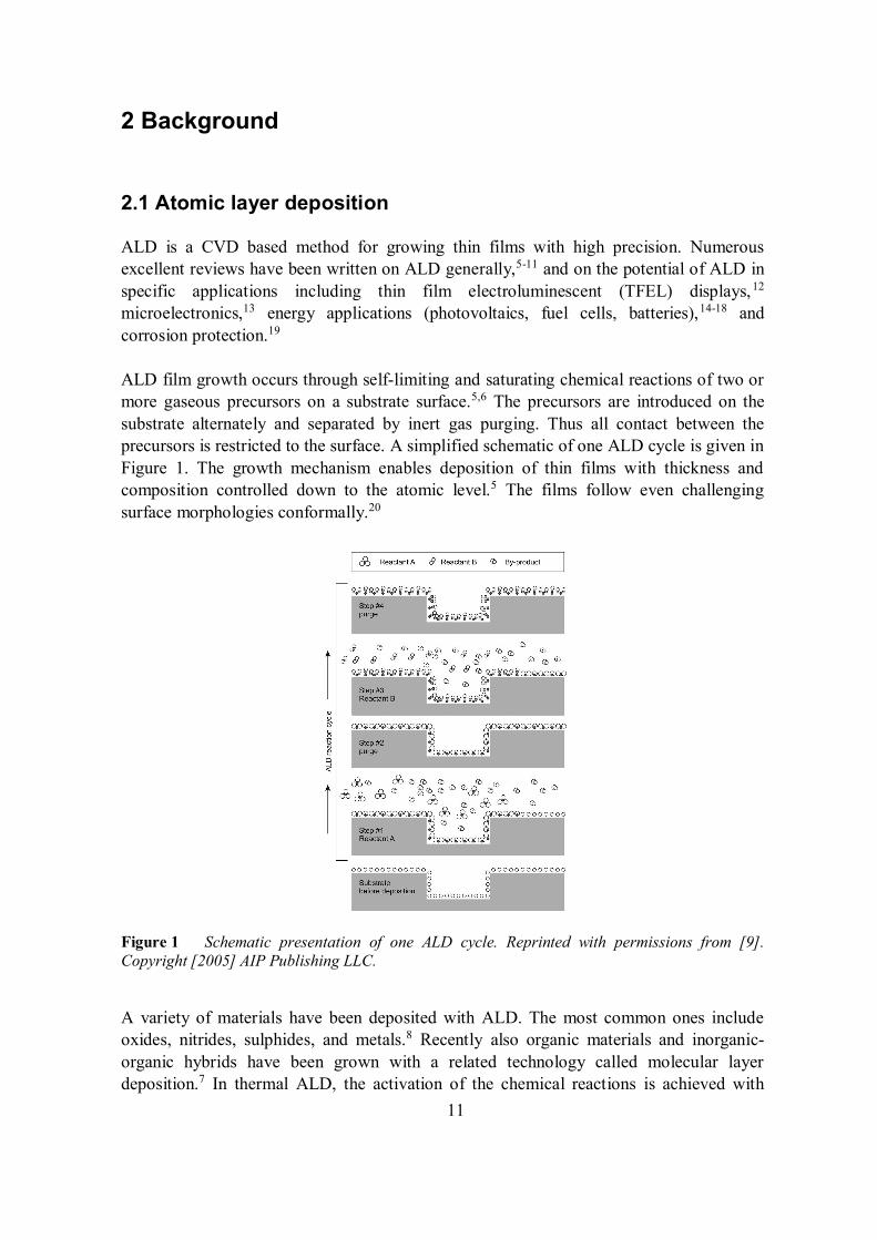
ALD film growth occurs through self-limiting and saturating chemical reactions of two ormore gaseous precursors on a substrate surface.5,6 The precursors are introduced on thesubstrate alternately and separated by inert gas purging. Thus all contact between theprecursors is restricted to the surface. A simplified schematic of one ALD cycle is given inFigure 1. The growth mechanism enables deposition of thin films with thickness andcomposition controlled down to the atomic level.5 The films follow even challengingsurface morphologies conformally.20
Figure 1 Schematic presentation of one ALD cycle. Reprinted with permissions from [9].Copyright [2005] AIP Publishing LLC.
A variety of materials have been deposited with ALD. The most common ones includeoxides, nitrides, sulphides, and metals.8 Recently also organic materials and inorganic-organic hybrids have been grown with a related technology called molecular layerdeposition.7 In thermal ALD, the activation of the chemical reactions is achieved with
12
heat.5,6 However, additional energy can be introduced through activation of the precursorsas in plasma-enhanced ALD (PEALD), radical-enhanced ALD and photo-inducedALD.10,21
Both the main benefits and challenges of ALD in growing corrosion protection coatingscan be derived from the unique growth mechanism. Conformal and precise layers can begrown in regards of structure and composition.5,6,20 Therefore, the coatings can be tailoredfor the needs of a specific application. Compared to many methods like painting, sol-gel,PVD, and CVD the conformality of ALD ensures that surfaces with complex shapes canbe equally encapsulated, and therefore burial of surface features under thick layers is notnecessary. Also post-deposition treatments like annealing, which are needed for instancewith sol-gel coatings, are rarely needed for ALD corrosion protection coatings.Furthermore, the defect density of ALD films is known to be very low,22,23 enablingcomplete sealing of surfaces with very thin layers. Therefore, the dimensions andmorphology of the original surface can be maintained.
The main challenge of ALD is the low growth rate leading to economical infeasibility ofthick coatings.6 Although chemical protection from the environment can be achievedalready with thin coatings, protection against mechanical wear might be limited.Furthermore, as the growth occurs through chemical reactions on the substrate surface, theproperties of ALD films are affected by the substrate.22-25 Most applications utilizing ALDfilms are on highly defined substrates like silicon or previously deposited layers.6,13-18 Inthese systems the composition of the substrate surface is known and can be modified toensure better ALD growth, if deemed necessary. In corrosion protection, heterogeneoussurfaces with unknown and varying composition are common. In addition, the surfaces ofbulk metals and metal alloys can be rough and contain particles that may upon detachmentform defected sites that expose the protected material. Often the substrates have beenmachined at workshops, and may be protected with oils to prevent corrosion duringhandling and/or storing. These issues can lead to unideal ALD nucleation, poor adhesionand insufficient protection with ultra-thin layers.
2.2 Corrosion protection with atomic layer deposited coatings
In this chapter the properties ALD films as corrosion protection coatings are reviewed.Main emphasis is given to the protection of metals and metallic constituents inmultimaterial structures. However, some general references are also made to the moststudied applications utilizing protective ALD coatings on non-metallic surfaces. In thefirst section the most common ALD materials in protective applications are presented withsome process and general material related details. The second section is focused onprotection of surfaces against gaseous corrosives. The permeation barrier properties ofALD films for common corrosive gases in the atmosphere are mainly recounted, butimprovement of durability at elevated temperatures is also considered. In the third sectionprotection against liquid corrosives is reviewed. The sealing properties and chemical
13
durability of the ALD coatings are especially focused on. The final section gives a shortreview on preventing out-diffusion of metals from the substrate into active device layersand inter-diffusion of metals from one active layer to another causing performancedegradation.
2.2.1 Materials
2.2.1.1 Oxides
By far the most frequently used ALD corrosion protection coating is Al2O3 and it is almostalways deposited from trimethyl aluminium (Al(CH3)3) and water.19,26-30 The main reasonfor this is that the process is almost ideal,9 can be successfully used in a wide temperaturerange of 33–500 °C,9,31,32 the films are amorphous as deposited and do not crystallisebelow 800 °C,8,33 and the precursors are relatively cheap. The films are quite pure, and thepurity is improved with increasing deposition temperature.9,31,32 For instance, thehydrogen impurity content decreases from 21.7 at.% at 33 °C to 1.0 at.% at 250 °C.31,32
Low carbon impurity contents have been reported at all deposition temperatures (<0.2at.% at 250 °C). The decrease of the impurity content with deposition temperature isattributed to more complete surface reactions afforded by the increased energy budget.5
Although ALD Al2O3 growth on a variety of different substrates has been shown, thesubstrate has also been shown to have an influence on the film properties.22-25 Problems inthe growth are often suggested to relate to the shortage of appropriate reactive groups (–OH) on the substrate surface. In the case of Pt, Cu, and stainless steel foils also thesubstrate roughness has been claimed to impede proper nucleation.24 Some recent workhas shown that the hardness, Young´s modulus and residual stress of ALD Al2O3 aredependent on the deposition temperature.34 The film thickness did not appear to have asignificant influence on the mechanical properties. Bulk Al2O3 is stable in neutralsolutions, but is dissolved in acidic and basic solutions.35 However, some susceptibility ofALD Al2O3 thin films even to deionised water has been reported.36
Some studies use ALD Al2O3 grown from Al(CH3)3 and O3 or PEALD Al2O3 grown fromAl(CH3)3 and O2 plasma as protective coatings.37,38 The main differences of thoseprocesses from the Al(CH3)3-H2O process are that better quality films can be deposited atlow deposition temperatures,10 and better nucleation and adhesion to challenging surfaceswith unideal chemical species for nucleation can be achieved.37,39 These differences arisefrom the higher reactivity of O3 and O2 plasma compared to H2O.10 However, possibledamage to the substrate during the coating process should also be considered for eachapplication. Furthermore, Al2O3 films deposited using O3 or especially O2 plasma may nothave the same level of conformality on complex surface morphologies that can beachieved with the H2O-based process.40
14
Another frequently used ALD material for corrosion protection coatings is TiO2.19,26,41,42
For protective applications TiO2 is commonly deposited from titanium tetrachloride(TiCl4) or titanium isopropoxide (Ti[OCH(CH3)2]4) with H2O.19,26,42,43 Sometimes morereactive oxygen sources (e.g. H2O2 or O3) are used.41,44 The main characteristics of theseprocesses are well documented and especially the TiCl4-H2O process can also be used in awide temperature range.8,45,46 Different from Al2O3, ALD TiO2 films can bepolycrystalline as deposited.8 Besides the deposition temperature, the crystallisation isdependent on the precursors, substrate and film thickness. Generally, anatase formationcan be observed around 125–680 °C from TiCl4-H2O and 150–350 °C fromTi[OCH(CH3)2)4]-H2O.8,45,46 Rutile formation can start at 275 °C depending on theprocess. Similar to Al2O3, the film purity can be improved by increasing the depositiontemperature. For instance, TiO2 deposited with the TiCl4-H2O process contained 0.3 at.%hydrogen when deposited at 150 °C and 0.1 at.% at 500 °C.46 The chloride contentdecreased from 2 at.% at 150 °C to below the detection limit of Rutherford backscatteringspectrometry at 500 °C. Bulk TiO2 is chemically more stable than Al2O3,35 and is thusexpected to withstand aggressive solutions better also in the thin film form. PolycrystallineALD TiO2 on silicon has been observed to resist etching in H2SO4 solutions better than acorresponding amorphous TiO2 film.47 However, the grain boundaries in polycrystallinefilms may act as preferential routes for corrosives to the protected surface.48
Other ALD oxides used for corrosion protection include Ta2O5,26 SiO2,30,49 ZrO2,50,51
ZnO,52,53 and HfO2.51 A variety of ALD processes exist for these materials,8 but incorrosion protection the most commonly used precursors are H2O with tantalumpentaethoxide (Ta[OCH2CH3]5) for Ta2O5,26 tetrakis(dimethylamino)zirconium(Zr[N(CH3)2]4) or tetrakis(ethylmethylamino)zirconium (Zr[N(CH3)(C2H5)]4) forZrO2,50,51 diethyl zinc (Zn(C2H5)3) for ZnO,52,53 and tetrakis(dimethylamino)hafnium(Hf[N(CH3)2]4) for HfO2.51 SiO2 is usually deposited with the rapid ALD process fromtris(tert-butoxy)silanol ([(CH3)3CO]3SiOH) or tris(tert-pentoxy)silanol([CH3CH2C(CH3)2O]3SiOH) with Al(CH3)3 as the catalyst.30,49 General properties of allthe processes are well documented in the literature.8 The Ta2O5 and SiO2 films areamorphous as deposited, but polycrystalline films of ZrO2, ZnO, and HfO2 can be grownfrom the above-mentioned precursors in appropriate conditions. The chemical durabilitiesof Ta2O5, SiO2, ZrO2 and HfO2 are known to be better than those of Al2O3.35,47
2.2.1.2 Nitrides
ALD and PEALD nitrides are used mainly as diffusion barriers rather than corrosionprotection coatings.54-57 A number of materials and ALD processes have been studied,8 butwithin this work only some general trends are presented. The two most commonly studieddiffusion barrier nitrides are TiN and TaN, others including WN, NbN, MoN and VN. Themost widely used precursors are halides like TiCl4 and TaCl5 with NH3 in ALD and withN2, H2 or NH3 plasmas in PEALD.54-57 For TiN the processes are relativelystraightforward,46,56-58 but for TaN the reduction of Ta(V) to Ta(III), as required for the
15
formation of the desired phase, is challenging.59 For instance, the ALD halide processeswith NH3 usually result in Ta3N5, which has a high resistivity. TaN can be formed whenan additional reducing agent like Zn or Al(CH3)3 is used,58,59 or with a more reducingnitrogen precursor instead of NH3.60 However, the additional or more complex precursorsmay also result in incorporation of additional impurities in the films. Commonly studiedmetalorganic precursors in diffusion barrier studies are alkylamides liketetrakis(dimethylamino)titanium (Ti[N(CH3)2]4), and tetrakis(ethylmethylamino)titanium(Ti[N(CH3)(C2H5)]4).56,61 The main benefits compared to the halide processes are the lessaggressive by-products, which do not degrade the substrate or the growing film, andavoidance of halide impurities from the films.62 However, the thermal stability of theamide precursors is poor.63
Similar to the ALD oxides, impurity contents in the nitride films are decreased withincreasing deposition temperatures. For instance, Ta(Al)N(C) deposited with the TaCl5-Al(CH3)3-NH3 process contain 14 at.% chloride at 250 °C and 4 at.% at 400 °C.54 Thehydrogen impurity content is similarly reduced from 14 to 7 at.%. The nitride films areusually crystalline as deposited.8 However, with the metalorganic precursors likeTi[N(CH3)2]4 amorphous films can be grown at low temperatures. The resistivities of theALD nitrides are dependent on the impurity contents and crystallinity of thefilms.54,57,58,64,65 The Cl impurities in particular have been shown to increase theresistivities.54,58 Low resistivities (~200 cm) have been reported for TiN.56-58,61 Also forTaN low resistivities (<500 cm) can be achieved,55,62 but only if the correct phase isobtained and the films are pure enough. The Ta3N5 phase is semiconducting,59 and TaNfilms with high impurity contents have resistivities of >1000 cm.54,66 Resistivitiesranging from a few hundred to over thousand cm have been reported for the other ALDnitrides.65,67-69
2.2.2 Protection against gaseous corrosives
ALD thin films have been shown to provide protection against the most commoncorrosives in the atmosphere. The main focus has been in inhibiting exposure of functionalmaterials to O2 and moisture. ALD gas permeation barriers have been widely consideredon polymers for food packaging44 and organic devices like light-emitting diodes(OLED),29,30,38,42,50,70-73 thin film transistors (OTFT),74 and photovoltaics (OPV).15,16
Permeation barriers are also needed in fully inorganic structures like Cu(In,Ga)Se2 (copperindium gallium selenide, CIGS) solar cells,15,16 zinc-tin-oxide based thin film transistors,75
and TFEL displays.5,12 The most actively studied application areas for protecting metalsfrom gaseous corrosives with ALD are nanoparticles in general,28,41,76-78 and silver andcopper nanostructures used for plasmon-enhanced analysis techniques.27,79-87 Single papershave also been published on a variety of other applications.52,88-95 In addition to increasedambient durability, also improvement of the oxidation resistance during annealing hasbeen shown.76-78,88,90,92,94-96 Silver tarnishing due to sulphur containing compounds has
16
been slowed down in applications where the visual appearance is of great importance.Some examples include jewels and historical artefacts.97-100
2.2.2.1 Applications
Studies on protective ALD coatings on metals and metal nanostructures against gaseouscorrosives are very varied and scattered in regards of applications. They include forinstance protection of copper rollers used as molds in hot emboss patterning of polymericcomponents,88 molybdenum walls in a microreactor,90 plasmonic silver and coppernanostructures on substrates for analysis devices like biosensors, surface-enhanced Ramanscattering (SERS) and femtosecond laser excitation,27,79-87 and copper nanowires aimed astransparent electrodes.52 In addition, prevention of spontaneous combustion of metallicnanoparticles,28,76,77 and preparation of functionalised nanoparticles with ambientdurability41,78 have been studied. The most studied protective material isAl2O3,28,41,76,77,79,81-93,95 but also TiO2, SiO2 and HfO2 single layers, Al2O3-ZnS and AlN-TiO2 nanolaminates and Al2O3 doped ZnO have been considered.41,52,77,78,80,94-96 Becausethe applications are so varied, drawing general requirements for the coatings or restrictionsfor the deposition conditions is challenging. However, usually the properties of theunderlying metals should be preserved during the ALD process, and in some applications,like when protecting plasmonic nanoparticles, the ALD coating should be thin enough tomaintain the intended functionality of the underlying metal.
For silver jewels and historical artefacts the protective ALD coatings are already in use.97-
100 In research, the aim has been to afford the maximum protection with a minimum effecton the visual appearance. Also the other properties of the substrates should be carefullymaintained, and the coatings on historical artefacts should preferably be easily removable.Thus, so far the only studied ALD coating materials have been Al2O3 and Al2O3-TiO2
nanolaminate. The thicknesses of the coatings have been tailored to maintain the originalvisual appearance.
Encapsulation of polymers used for food packaging and organic and inorganic devices iswidely studied with ALD permeation barriers.15,16,29,30,38,42,44,50,70-75,101-109 The performanceof the layers is commonly evaluated by water vapour transmission (WVTR) and oxygentransmission (O2TR) rates. WVTRs and O2TRs in the order of 0.01–100 g/(m2 day) and0.01–100 cm3/(m2 day) are required for sensitive food products.44 However, therequirements for organic and inorganic electronic devices are more stringent. Thesuggested limits for WVTR and O2TR are in the order of 10-6 g/(m2 day) and 10-5–10-3
cm3/(m2 day) for stable long-term performance.50,105,110 In addition, process restrictionslike temperature and precursors must be considered, as the functionality of the previouslydeposited layers should not be compromised.38,109 The most actively studied ALDpermeation barrier materials are Al2O3, TiO2, SiO2 and ZrO2.29,30,38,42,44,50,70-74,105,106,108
17
2.2.2.2 Influence of deposition parameters
Systematic research on the influence of deposition parameters on the permeationresistance of ALD coatings is quite limited on plain metallic substrates. Thus somegeneral guidelines are borrowed from the numerous permeation barrier studies onpolymers and device structures for OLEDs, OTFTs and OPVs. However, as the substratehas an influence on the ALD thin film properties,24,25 straightforward analogy of theresults cannot be assumed.
In addition to the intrinsic properties of the ALD materials, the depositiontemperature,38,44,70 coating thickness38,44,70-73 and reactivity of the oxygenprecursor38,44,50,73 have been shown to be critical for the permeation barrier properties onpolymers. The steady-state permeation of water and oxygen through good barrier oxideshas been suggested to occur through pinholes,30,70,72,111,112 or along –OH groups existingdue to hydrogen impurities.31,70 The impurity content of ALD films significantly decreaseswith increasing deposition temperature.5 The increasing deposition temperature is thusassumed to have a positive effect on the permeation barrier properties. For instance, thebarrier properties of Al2O3 on polyethylene terephtalate significantly increased withincreasing deposition temperature from 50 to 100 °C.70 However, on heat sensitivesubstrates, like polymers, the upper temperature limit is usually set by the durability andstability of the substrate. Furthermore, if the deposition temperature is too high, filmcracking can occur upon cooling after the deposition due to differences in the thermalexpansion coefficients of the substrate and the film.35 Most permeation barrier studieshave been done at deposition temperatures of 150 °C.
With bulk metal substrates higher deposition temperatures can be used than withpolymers. The responses of the ALD oxide coatings and the substrate to heating are closerto each other, and generally metals themselves are not as sensitive to heat as polymers.35
On Cu plates an increase of the Al2O3 deposition temperature from 100 to 200 °C has beenshown to improve the oxidation resistance and adhesion of the coatings.88 However,nanostructured and highly oxidizing metals might induce similar temperature restrictionsas polymers due to sintering or oxidation during the first ALD cycles. For instance, on Fe,Co and Ag nanoparticles and -columns ALD oxide coatings have been deposited at 50–180 °C to restrict morphological and compositional changes during thedepositions.76,78,86,87,93 Additionally, at high deposition temperatures the possiblecrystallisation of the protective ALD film must be considered. Upon crystallisation grainboundaries, which offer an easier passage for corrosives to the protected surface, areintroduced into the coating.48
The impurity contents of ALD coatings deposited at low temperatures can be decreased byusing reactive oxygen precursors. Replacing H2O with O3, H2O2 or O2 plasma has beenshown to be beneficial for Al2O3, TiO2 and ZrO2 coatings on polymers andmetals.38,41,44,50,73,78 However, when choosing the ALD process, care should be taken alsoto ensure that the precursors themselves do not change properties of the substrate. For
18
instance, O2 plasma has been observed to degrade the functional layers of an OLEDstructure,109 and H2O2 to oxidise the surface of Fe nanoparticles.78
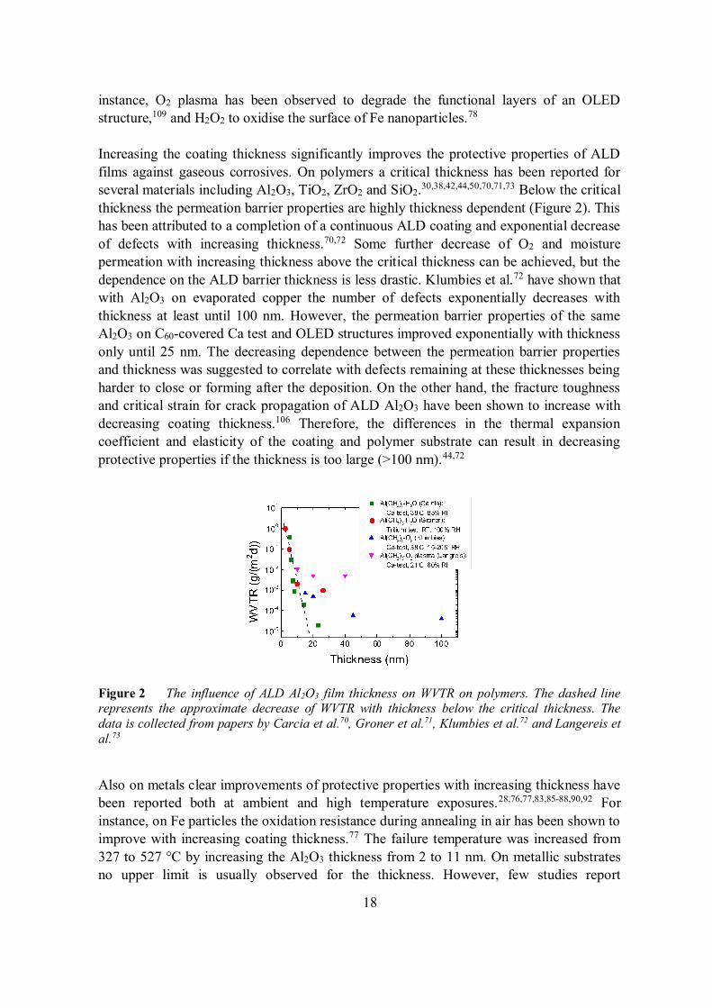
Increasing the coating thickness significantly improves the protective properties of ALDfilms against gaseous corrosives. On polymers a critical thickness has been reported forseveral materials including Al2O3, TiO2, ZrO2 and SiO2.30,38,42,44,50,70,71,73 Below the criticalthickness the permeation barrier properties are highly thickness dependent (Figure 2). Thishas been attributed to a completion of a continuous ALD coating and exponential decreaseof defects with increasing thickness.70,72 Some further decrease of O2 and moisturepermeation with increasing thickness above the critical thickness can be achieved, but thedependence on the ALD barrier thickness is less drastic. Klumbies et al.72 have shown thatwith Al2O3 on evaporated copper the number of defects exponentially decreases withthickness at least until 100 nm. However, the permeation barrier properties of the sameAl2O3 on C60-covered Ca test and OLED structures improved exponentially with thicknessonly until 25 nm. The decreasing dependence between the permeation barrier propertiesand thickness was suggested to correlate with defects remaining at these thicknesses beingharder to close or forming after the deposition. On the other hand, the fracture toughnessand critical strain for crack propagation of ALD Al2O3 have been shown to increase withdecreasing coating thickness.106 Therefore, the differences in the thermal expansioncoefficient and elasticity of the coating and polymer substrate can result in decreasingprotective properties if the thickness is too large (>100 nm).44,72
Figure 2 The influence of ALD Al2O3 film thickness on WVTR on polymers. The dashed linerepresents the approximate decrease of WVTR with thickness below the critical thickness. Thedata is collected from papers by Carcia et al.70, Groner et al.71, Klumbies et al.72 and Langereis etal.73
Also on metals clear improvements of protective properties with increasing thickness havebeen reported both at ambient and high temperature exposures.28,76,77,83,85-88,90,92 Forinstance, on Fe particles the oxidation resistance during annealing in air has been shown toimprove with increasing coating thickness.77 The failure temperature was increased from327 to 527 °C by increasing the Al2O3 thickness from 2 to 11 nm. On metallic substratesno upper limit is usually observed for the thickness. However, few studies report
19
protective coatings thicker than 100 nm.90 On the other hand, ultra-thin coatings areneeded in some applications to minimise the influence of the protective layers on thefunctionality of the protected material.27,79-81,83-87 For instance, the intensity of theelectromagnetic waves from a Ag nanoparticle surface plasmon show an exponentialdecay with increasing distance from the silver surface.87 Thus 1 nm thick protectivelayers are preferred in the ALD protected SERS substrates, and ultra-thin Al2O3 coatingswere shown to afford ambient durability up to 9 months.
2.2.2.3 Comparison of coating materials
The most actively studied protective ALD material against gaseous corrosives onpolymers is Al2O3.29,30,38,42,44,70-74 Also TiO2, ZrO2 and SiO2 have gained attention.30,42,44,50
The WVTR and critical thickness of Al2O3 have been found to be lower than thecorresponding values for the other oxides (Table 1).30,38,42,44,50,70-73 Possible reasons are theideal nature of the ALD Al2O3 process (Al(CH3)3-H2O)9 and the better nucleation of Al2O3
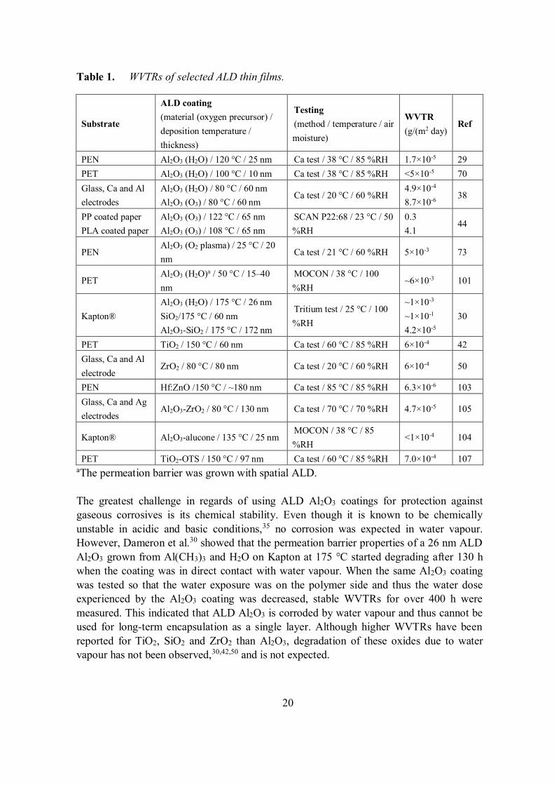
on polymers.25 The best reported WVTR values for ALD Al2O3 are generally in the orderof 10-3–10-6 g/(m2 day) for 20–100 nm thick coatings.29,38,70-73 The high variability isprobably due to differences in the reactive groups of the polymer substrates, ALDprocesses, and sensitivity of the testing methods. WVTRs in the order of ~10-4 g/(m2 day)have been reported for TiO2 and ZrO2 with coating thickness between 50–80 nm.42,50 Thereported permeation barrier properties of SiO2 coatings are poor.30 The WVTR of a 60 nmcoating was 1×10⁻¹ g/(m2 day).
20
Table 1. WVTRs of selected ALD thin films.
Substrate
ALD coating(material (oxygen precursor) /deposition temperature /thickness)
Testing(method / temperature / airmoisture)
WVTR(g/(m2 day)
Ref
PEN Al2O3 (H2O) / 120 °C / 25 nm Ca test / 38 °C / 85 %RH 1.7×10⁻⁵ 29PET Al2O3 (H2O) / 100 °C / 10 nm Ca test / 38 °C / 85 %RH <5×10⁻⁵ 70Glass, Ca and Alelectrodes
Al2O3 (H2O) / 80 °C / 60 nmAl2O3 (O3) / 80 °C / 60 nm
Ca test / 20 °C / 60 %RH4.9×10-4
8.7×10⁻⁶ 38
PP coated paperPLA coated paper
Al2O3 (O3) / 122 °C / 65 nmAl2O3 (O3) / 108 °C / 65 nm
SCAN P22:68 / 23 °C / 50%RH
0.34.1
44
PENAl2O3 (O2 plasma) / 25 °C / 20nm
Ca test / 21 °C / 60 %RH 5×10⁻³ 73
PETAl2O3 (H2O)a / 50 °C / 15–40nm
MOCON / 38 °C / 100%RH
~6×10⁻³ 101
Kapton®Al2O3 (H2O) / 175 °C / 26 nmSiO2/175 °C / 60 nmAl2O3-SiO2 / 175 °C / 172 nm
Tritium test / 25 °C / 100%RH
~1×10⁻³
~1×10⁻¹
4.2×10⁻⁵
30
PET TiO2 / 150 °C / 60 nm Ca test / 60 °C / 85 %RH 6×10⁻⁴ 42Glass, Ca and Alelectrode
ZrO2 / 80 °C / 80 nm Ca test / 20 °C / 60 %RH 6×10⁻⁴ 50
PEN Hf:ZnO /150 °C / ~180 nm Ca test / 85 °C / 85 %RH 6.3×10⁻⁶ 103Glass, Ca and Agelectrodes
Al2O3-ZrO2 / 80 °C / 130 nm Ca test / 70 °C / 70 %RH 4.7×10⁻⁵ 105
Kapton® Al2O3-alucone / 135 °C / 25 nmMOCON / 38 °C / 85%RH
<1×10⁻⁴ 104
PET TiO2-OTS / 150 °C / 97 nm Ca test / 60 °C / 85 %RH 7.0×10⁻⁴ 107aThe permeation barrier was grown with spatial ALD.
The greatest challenge in regards of using ALD Al2O3 coatings for protection againstgaseous corrosives is its chemical stability. Even though it is known to be chemicallyunstable in acidic and basic conditions,35 no corrosion was expected in water vapour.However, Dameron et al.30 showed that the permeation barrier properties of a 26 nm ALDAl2O3 grown from Al(CH3)3 and H2O on Kapton at 175 °C started degrading after 130 hwhen the coating was in direct contact with water vapour. When the same Al2O3 coatingwas tested so that the water exposure was on the polymer side and thus the water doseexperienced by the Al2O3 coating was decreased, stable WVTRs for over 400 h weremeasured. This indicated that ALD Al2O3 is corroded by water vapour and thus cannot beused for long-term encapsulation as a single layer. Although higher WVTRs have beenreported for TiO2, SiO2 and ZrO2 than Al2O3, degradation of these oxides due to watervapour has not been observed,30,42,50 and is not expected.
21
A number of papers report protection of metals with ALD Al2O3 coatings during storagein ambient and exposure to high temperatures.28,41,76,77,79,81-93,95 All these protective Al2O3
layers have been deposited with the Al(CH3)3-H2O process,28,41,76,77,79,81,83-89,91-93,95 or theprocess has not been specified.82,90 Improved ambient durability has been shown for cobaltnanopillars,93 nickel-chromium-copper-aluminium-germanium alloy resistors,89 silvernanoparticles,87 gold and silver pyramids,82 and chromium-gold electrodes.91 Increasedhigh temperature durability has been reported for iron nanoparticles,28,76,77 copper,88
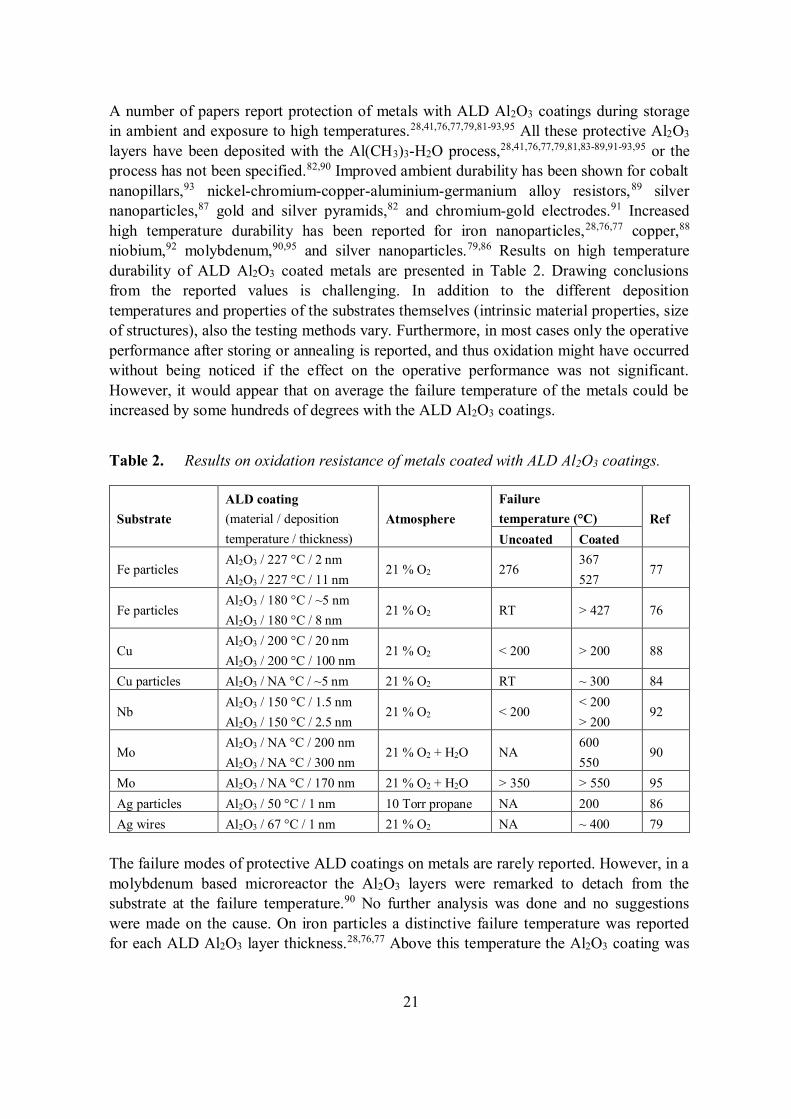
niobium,92 molybdenum,90,95 and silver nanoparticles.79,86 Results on high temperaturedurability of ALD Al2O3 coated metals are presented in Table 2. Drawing conclusionsfrom the reported values is challenging. In addition to the different depositiontemperatures and properties of the substrates themselves (intrinsic material properties, sizeof structures), also the testing methods vary. Furthermore, in most cases only the operativeperformance after storing or annealing is reported, and thus oxidation might have occurredwithout being noticed if the effect on the operative performance was not significant.However, it would appear that on average the failure temperature of the metals could beincreased by some hundreds of degrees with the ALD Al2O3 coatings.
Table 2. Results on oxidation resistance of metals coated with ALD Al2O3 coatings.
SubstrateALD coating(material / depositiontemperature / thickness)
AtmosphereFailuretemperature (°C) RefUncoated Coated
Fe particlesAl2O3 / 227 °C / 2 nmAl2O3 / 227 °C / 11 nm
21 % O2 276367527
77
Fe particlesAl2O3 / 180 °C / ~5 nmAl2O3 / 180 °C / 8 nm
21 % O2 RT > 427 76
CuAl2O3 / 200 °C / 20 nmAl2O3 / 200 °C / 100 nm
21 % O2 < 200 > 200 88
Cu particles Al2O3 / NA °C / ~5 nm 21 % O2 RT ~ 300 84
NbAl2O3 / 150 °C / 1.5 nmAl2O3 / 150 °C / 2.5 nm
21 % O2 < 200< 200> 200
92
MoAl2O3 / NA °C / 200 nmAl2O3 / NA °C / 300 nm
21 % O2 + H2O NA600550
90
Mo Al2O3 / NA °C / 170 nm 21 % O2 + H2O > 350 > 550 95Ag particles Al2O3 / 50 °C / 1 nm 10 Torr propane NA 200 86Ag wires Al2O3 / 67 °C / 1 nm 21 % O2 NA ~ 400 79
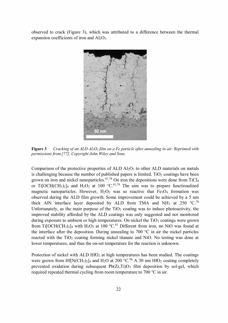
The failure modes of protective ALD coatings on metals are rarely reported. However, in amolybdenum based microreactor the Al2O3 layers were remarked to detach from thesubstrate at the failure temperature.90 No further analysis was done and no suggestionswere made on the cause. On iron particles a distinctive failure temperature was reportedfor each ALD Al2O3 layer thickness.28,76,77 Above this temperature the Al2O3 coating was
22
observed to crack (Figure 3), which was attributed to a difference between the thermalexpansion coefficients of iron and Al2O3.
Figure 3 Cracking of an ALD Al2O3 film on a Fe particle after annealing in air. Reprinted withpermissions from [77]. Copyright John Wiley and Sons.
Comparison of the protective properties of ALD Al2O3 to other ALD materials on metalsis challenging because the number of published papers is limited. TiO2 coatings have beengrown on iron and nickel nanoparticles.41,78 On iron the depositions were done from TiCl4
or Ti[OCH(CH3)2]4 and H2O2 at 100 °C.41,78 The aim was to prepare functionalisedmagnetic nanoparticles. However, H2O2 was so reactive that Fe3O4 formation wasobserved during the ALD film growth. Some improvement could be achieved by a 5 nmthick AlN interface layer deposited by ALD from TMA and NH3 at 250 °C.78
Unfortunately, as the main purpose of the TiO2 coating was to induce photoactivity, theimproved stability afforded by the ALD coatings was only suggested and not monitoredduring exposure to ambient or high temperatures. On nickel the TiO2 coatings were grownfrom Ti[OCH(CH3)2]4 with H2O2 at 100 °C.41 Different from iron, no NiO was found atthe interface after the deposition. During annealing to 700 °C in air the nickel particlesreacted with the TiO2 coating forming nickel titanate and NiO. No testing was done atlower temperatures, and thus the on-set temperature for the reaction is unknown.
Protection of nickel with ALD HfO2 at high temperatures has been studied. The coatingswere grown from Hf[N(CH3)2]4 and H2O at 200 °C.94 A 30 nm HfO2 coating completelyprevented oxidation during subsequent Pb(Zr,Ti)O3 film deposition by sol-gel, whichrequired repeated thermal cycling from room temperature to 700 °C in air.
23
ALD SiO2 coatings were used to protect silver nanohole arrays for surface plasmonresonance biosensing.80 Coatings of 15 nm thickness deposited from [(CH3)3CO]3SiOHwith Al(CH3)3 catalyst at 100 °C prevented silver oxidation during a 5 min exposure to O2
plasma under ultraviolet light.
2.2.2.4 Multilayer and mixture coatings
Enhanced permeation barrier properties on polymers have been reported for ALD layerscombining two or more materials.30,102,105,108 Usually Al2O3 as an excellent permeationbarrier is combined with another chemically more durable material. Examples includeAl2O3-SiO2,30 Al2O3-TiO2,108, Al2O3-HfO2,102 and Al2O3-ZrO2 nanolaminates.105 WVTRand O2TRs in the order of 10-4–10-5 g/(m2 day) and 10-2 cm3/(m2 day) have beenreported,30,102,105,108 and the performance can be maintained for extensive time periods upto 10 000 h.102 In addition to combining good barrier properties with chemical durability,another suggested reason for the improved behaviour is disruption of through-coatingdefects by separation of crystallised layers with amorphous ones.105 Also inorganic-organic nanolaminates have been studied with the aim of improving the elasticity of thecoatings.104,107
The publications on ALD nanolaminate or mixture coatings for preventing degradationdue to gaseous corrosives are significantly scarcer on plain metals than on polymers.52,77,97
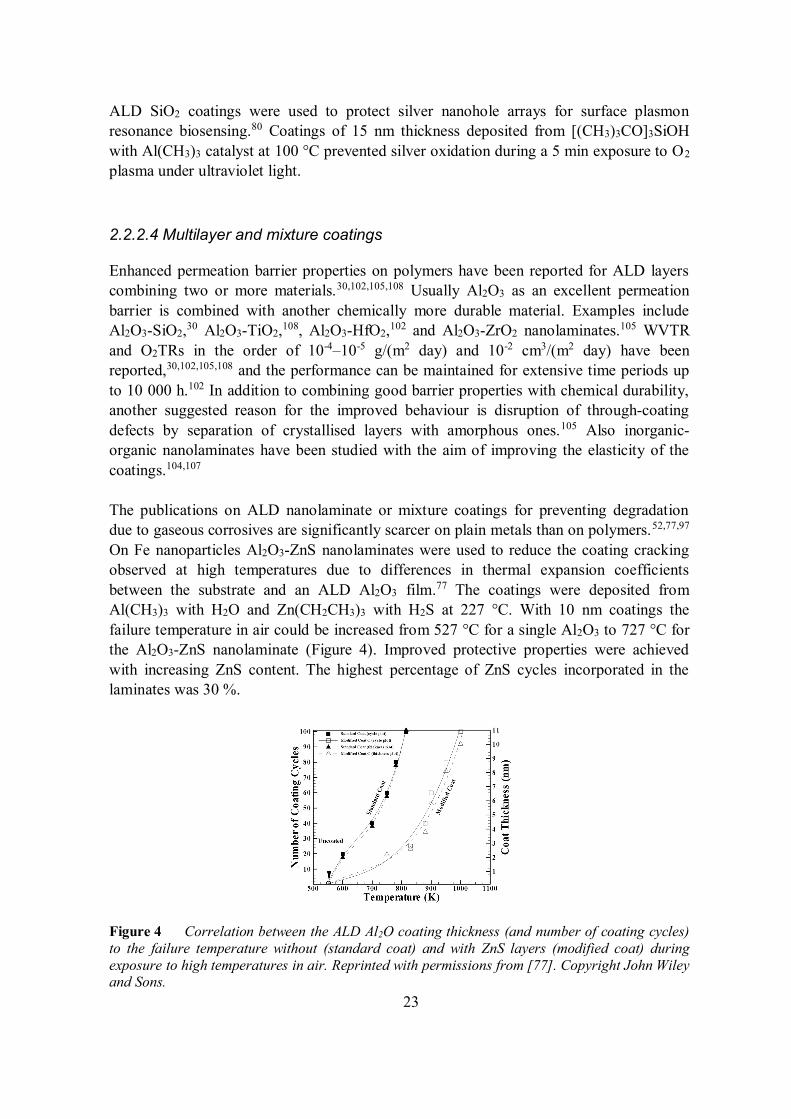
On Fe nanoparticles Al2O3-ZnS nanolaminates were used to reduce the coating crackingobserved at high temperatures due to differences in thermal expansion coefficientsbetween the substrate and an ALD Al2O3 film.77 The coatings were deposited fromAl(CH3)3 with H2O and Zn(CH2CH3)3 with H2S at 227 °C. With 10 nm coatings thefailure temperature in air could be increased from 527 °C for a single Al2O3 to 727 °C forthe Al2O3-ZnS nanolaminate (Figure 4). Improved protective properties were achievedwith increasing ZnS content. The highest percentage of ZnS cycles incorporated in thelaminates was 30 %.
Figure 4 Correlation between the ALD Al2O coating thickness (and number of coating cycles)to the failure temperature without (standard coat) and with ZnS layers (modified coat) duringexposure to high temperatures in air. Reprinted with permissions from [77]. Copyright John Wileyand Sons.
24
Al2O3-TiO2 nanolaminates (90 nm) have been used to prevent tarnishing of silver.97,100
The precursors, deposition temperature and single layer thicknesses were not disclosed. Inaccelerated tioacetamide corrosion test (ISO 4538:1978) the bare silver showed significantdegradation already after 1 hour, but the ALD coated samples remained almost Ag2S freefor 48 h. The aim of using nanolaminates instead of single layers of Al2O3 or TiO2 was notgiven, but possibly the combination of the barrier properties of Al2O3 with the chemicalstability of TiO2 was attempted. Additionally thicker protective coatings could be madeinvisible to the naked eye when the nanolaminate structure was adopted instead of singlelayers. No comparison was made to the protective properties of single layers of Al2O3 orTiO2.
Electrospun Cu nanowires intended to be used as a low cost transparent electrode wereprotected with ALD ZnO coatings doped with Al2O3.52 Zn(CH2CH3)3, Al(CH3)3 and H2Owere used as precursors and the deposition temperature was 150 °C. The material waschosen due to its transparency and conductivity. A 1 nm ALD Al2O3 layer was used as anucleation layer. The Al2O3 nucleation layer was also anticipated to improve the acidresistance of the coating. The oxidation resistance of the nanowires during annealing at160 °C in dry air was significantly improved by the coating. The bare wires werecompletely oxidised and turned insulating in 40 min while the 25 nm coated wires showedonly a 10 % increase in resistance after 8 h. The afforded protection was even moreapparent in humid conditions. Because the conductivity of the protective coating was vitalfor the application, no comparison in regards of protective properties was made to singlelayers of Al2O3 or ZnO.
2.2.3 Protection against liquid corrosives
Matero et al.26 were the first to consider the general corrosion protection properties ofALD coatings against liquid corrosives on metallurgical substrates. They studied theprotection of stainless steel. Similar studies have since been done on stainless steel,19,43,113-
118 steel,37 aluminium alloy,19,37 magnesium alloy,19,119-121 copper,19,53,122,123 and silver andsterling silver.19,97 In addition to the fundamental research on metallic substrates also ALDprotection of metals in applications like plasmon-enhanced dye-sensitised solar cells(DSSC),124,125 nanoparticles used for heterogeneous catalysis,126-129 biomedicaldevices,51,130-132 proteomics based on nanonewton dielectrophoretic forces133-135 andoptical components49,136 have been considered. Furthermore, combination of ALD withcoatings deposited by other methods has opened a pathway to utilise ALD coatings inapplications in which ALD layers alone might not offer sufficient protection for instancedue to limited mechanical durability.137-140 Hereafter these combination coatings arereferred to as duplex coatings. Protection of non-metallic surfaces from liquid corrosivesfor instance in lithium-ion batteries,14,141,142 molten carbonate fuel cells (MCFC),143-145 andphotoelectrochemical cells (PEC) for water splitting17 have also been widely studied withALD coatings.
25
2.2.3.1 Applications
Fundamental research on the electrochemical corrosion protection properties of ALDcoatings on metals has gained significant attention.19,26,37,43,53,97,113-123 Because no singleapplication is specifically considered, there have been no additional requirements for thecoatings. The general aim has been to produce as good sealing properties as possible toisolate the protected surface completely from the corrosive liquids. Additionally, the long-term stability and chemical durability should be optimised. The restrictions to the ALDprocesses are usually determined by the substrate. The most commonly studied protectivematerials have been Al2O3 and TiO2.19,26,37,43,53,113,114,116-123 In addition, Ta2O5 and AlNsingle layers and Al2O3-TiO2 nanolaminates have been considered.19,26,97,113-115,117-119
Several types of applications have gained attention in protecting metallic components inliquids by ALD. Silver nanoparticles can be incorporated in DSSCs to enhance the energyabsorption.124,125 However, the nanoparticles are easily corroded in the I-/I3
- redox shuttle,and their stabilisation with ALD TiO2 and Al2O3-TiO2 nanolaminate coatings has beenstudied. The protective coating should be as thin as possible to minimise the exponentiallydistance dependent extinction of the electromagnetic waves of the surface plasmons. Thisrequirement is similar to the one discussed in the previous chapter in regards of plasmon-enhanced analysis tools.
Copper and cobalt nanoparticles can be used in liquid-phase heterogeneous catalysis forconverting biomass to fuels and chemicals.126-129 The main challenge is to preventleaching and sintering of the metals during the process operation. ALD Al2O3 and TiO2
coatings have been studied. To enable catalysis on the particles, the protective ALD layersmust contain pores. This can be achieved by annealing ultrathin films at 500–700 °C.
Surfaces of several biomedical devices have been protected with ALD. In addition toprotecting the surfaces from degradation, in biomedical devices complete sealing is vitalalso to prevent exposure of living organisms to harmful substances. SiO2 has been used toprotect stainless steel implants.132 Al2O3 has been used to protect nickel-titanium alloysaimed for instance for stents.130 Al2O3 and Al2O3-HfO2 nanolaminates have been used toprotect aluminium contacts in complementary metal oxide semiconductor devices aimedfor biosensing.131 Al2O3, HfO2, ZrO2 and Al2O3-HfO2 nanolaminates have been tested formicroelectromechanical systems aimed generally for biomedical applications.51
Nanonewton dielectrophoretic forces can be used to selectively attach and detach proteinsto a surface for monitoring genetic and protein biomarkers.133-135 However, the currentlyused gold-chromium electrodes corrode in the required electric fields. Protection withALD SiO2 has been attempted. The coating should be quite thin to avoid unnecessaryvoltage loss across the protective layer.
Aluminium and silver reflectors in optical components are prone to corrode in theatmosphere and during exposure to corrosive liquids.49,136 Protection abilities of ALD
26
SiO2 and Al2O3 coatings have been considered. The main requirement is that the reflectiveproperties of the metal substrates must be maintained. Although specific applications areaimed for, the research has been quite fundamental.
Protective ALD coatings against liquid corrosives on non-metallic surfaces have been alsoused in several applications. Some actively studied areas include electrodes in Li-ionbatteries, MCFCs and PEC water splitting. In Li-ion batteries the electrode materialssuffer from chemical and mechanical degradation.14 Protective ALD coatings have beenmost actively studied on carbon, silicon, metal oxide, and their hybrid combinationanodes. Correspondingly the protection of LiCoO2, LiMn2O4, and more complex lithiummetal oxide cathodes has been studied. Al2O3 is the most common protective ALD coatingmaterial, but in addition TiO2, ZnO, ZrO2 and TiN have been considered.14,146 Theprotective layer should be very thin to minimise its influence to the ion and electrontransport to the electrodes.
In MCFCs the state-of-the-art nickel oxide cathode is prone to dissolve in the carbonatemelt (electrolyte).143-145 ALD TiO2, CeO2, and Co3O4 have been suggested as theprotective layers. The active nickel oxide phase is formed through electrochemicaloxidation/lithiation of nickel in the Li2CO3-K2CO3 electrolyte. The protective layer shouldallow the formation of the active layer or a layer with different composition but similarfunctional properties.
In PEC water splitting the semiconductor electrodes with sufficiently narrow band gaps toharvest energy from the visible light are susceptible to corrosion in the aggressive aqueouselectrolytes.17 Both anodes like Si, ZnO, GaAs and GaP,17,147,148 and cathodes like Si,Cu2O and InP17,149 have been protected with ALD coatings. Bulk of the research hasfocused on TiO2 coatings, but other studied materials include MnO and Al2O2:ZnO-TiO2
nanolaminates.17,147-149
2.2.3.2 Influence of deposition parameters
In chapter 2.2.2.2 it was elaborated that the ALD process, deposition temperature andcoating thickness significantly influence the performance of protective coatings againstgaseous corrosives. In liquids, the role of the substrate pre-treatment has been additionallyraised. Marin et al.115 considered the influence of two industrial surface finishes, picklingin HNO3 and HF (ASTM A480-2D) and skinpassing (ASTM A480-2B), on the protectiveproperties of ALD coatings on stainless steel. The pickling treatment produced a roughsurface (RMS 368 nm) with grain boundaries clearly visible while the skinpassing resultedin a smoother finish (RMS 52 nm) with oriented grooves along the direction of theskinpass. A 400 nm ALD Al2O3-TiO2 nanolaminate clearly improved the durability ofsubstrates pre-treated either way. No clear difference between the electrochemicalbehaviours of the coated samples with different pre-treatments could be observed. Thisimplies that the surface finish did not significantly influence the ALD coating
27
performance. However, it is possible that the 400 nm coating was too thick to adequatelyevaluate the influence of the pre-treatment. Furthermore, thus far no consideration hasbeen given to the influence of heterogeneous surface composition like segregated carbideson the surface of steels, or cleanliness. Potts et al.37 have shown that PEALD Al2O3
coatings adhere to steel better than thermal ALD coatings. The suggested cause was acleaning effect from the highly reactive O2 plasma in the beginning of the film deposition.
The most common process used in depositing ALD Al2O3 corrosion protection coatingsagainst liquid corrosives is Al(CH3)3–H2O.26,37,51,53,113,114,116-120,122-124,128-130,136 Only Pottset al.37 have used O2 plasma as the oxidizing precursor in addition to H2O. They comparedthe protective properties of thermal and PEALD Al2O3 coatings deposited at 150 °C onlow alloy steel and aluminium alloy. Thin 10 nm PEALD coatings were observed toperform significantly better than the corresponding thermal ALD coatings. This wasattributed to the lower amount of impurities observed in the PEALD coatings. However,already at 50 nm thickness the performance of the coatings was similar or even reversed.
ALD TiO2 corrosion protection coatings are usually deposited from TiCl4 andH2O,19,26,53,114,117-119 but also Ti(OCH(CH)2)4 and H2O have been used.43,124,125 Generally,non-chloride containing precursors would seem more appealing in depositing corrosionprotection coatings. Indeed, some microblistering has been observed under TiO2 coatingsdeposited from TiCl4 on stainless steel.114 Furthermore, the electrochemical barrierproperties have been observed to be similar for a 100 nm TiO2 deposited from TiCl4
114 anda thinner 50 nm TiO2 deposited from Ti(OCH(CH)2)4
43 on stainless steel. This implies thatbetter results can be achieved with the non-chloride containing precursor. However, directcomparison is challenging due to differences in substrate materials, coating thicknesses,deposition temperatures and testing methods.
For Ta2O5 and SiO2, similar considerations on the effect of the ALD process arechallenging. Either only single process has been studied or the testing methods are sodifferent that any comparison would be pointless.26,113,132-135
The amount of impurities in ALD films decrease with increasing deposition temperature.5
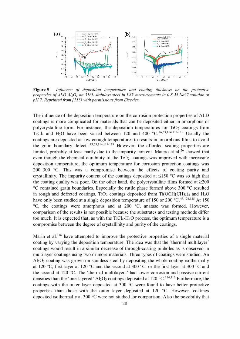
This leads to better quality films with higher density and lower defect density. Foramorphous ALD coatings, this has indeed been shown to improve the protective propertiesagainst liquid corrosives.26,37,113,116 Diaz et al.113 showed clear improvement ofelectrochemical corrosion protection properties of Al2O3 coatings with increasingdeposition temperature (Figure 5). On stainless steel the passive current density in linearsweep voltammetry (LSV) measurements was decreased by one order of magnitude whenincreasing the temperature from 160 to 250 °C. Potts et al.37 observed an almost lineardecrease in coating porosities from 4.5 to 0.5 % with increasing deposition temperaturefrom 50 to 150 °C for Al2O3 films deposited with PEALD on low alloy steel. Theporosities were calculated from corrosion current densities determined from LSV results.However, on aluminium alloy an increase of porosities with deposition temperature wasreported for PEALD Al2O3 without any clear indication on the cause.
28
Figure 5 Influence of deposition temperature and coating thickness on the protectiveproperties of ALD Al2O3 on 316L stainless steel in LSV measurements in 0.8 M NaCl solution atpH 7. Reprinted from [113] with permissions from Elsevier.
The influence of the deposition temperature on the corrosion protection properties of ALDcoatings is more complicated for materials that can be deposited either in amorphous orpolycrystalline form. For instance, the deposition temperatures for TiO2 coatings fromTiCl4 and H2O have been varied between 120 and 400 °C.26,53,114,117-119 Usually thecoatings are deposited at low enough temperatures to results in amorphous films to avoidthe grain boundary defects.43,53,114,117-119 However, the afforded sealing properties arelimited, probably at least partly due to the impurity content. Matero et al.26 showed thateven though the chemical durability of the TiO2 coatings was improved with increasingdeposition temperature, the optimum temperature for corrosion protection coatings was200–300 °C. This was a compromise between the effects of coating purity andcrystallinity. The impurity content of the coatings deposited at 150 °C was so high thatthe coating quality was poor. On the other hand, the polycrystalline films formed at 200°C contained grain boundaries. Especially the rutile phase formed above 300 °C resultedin rough and defected coatings. TiO2 coatings deposited from Ti(OCH(CH)2)4 and H2Ohave only been studied at a single deposition temperature of 150 or 200 °C.43,124,125 At 150°C, the coatings were amorphous and at 200 °C, anatase was formed. However,comparison of the results is not possible because the substrates and testing methods differtoo much. It is expected that, as with the TiCl4-H2O process, the optimum temperature is acompromise between the degree of crystallinity and purity of the coatings.
Marin et al.116 have attempted to improve the protective properties of a single materialcoating by varying the deposition temperature. The idea was that the ´thermal multilayer´coatings would result in a similar decrease of through-coating pinholes as is observed inmultilayer coatings using two or more materials. Three types of coatings were studied. AnAl2O3 coating was grown on stainless steel by depositing the whole coating isothermallyat 120 °C, first layer at 120 °C and the second at 300 °C, or the first layer at 300 °C andthe second at 120 °C. The ‘thermal multilayers’ had lower corrosion and passive currentdensities than the ‘one-layered’ Al2O3 coatings deposited at 120 °C.114,116 Furthermore, thecoatings with the outer layer deposited at 300 °C were found to have better protectiveproperties than those with the outer layer deposited at 120 °C. However, coatingsdeposited isothermally at 300 °C were not studied for comparison. Also the possibility that
29
the lower initial deposition temperature might protect the stainless steel during thesubsequent deposition at the higher temperature was not considered.
As was observed with gaseous corrosives, increasing the coating thickness significantlyimproved the corrosion protection properties of ALDcoatings.26,37,49,53,113,114,116,117,119,120,122-124,136 Compared to the gas environment, moresystematic research has been done on metals in corrosive liquids. On stainless steel, athree orders of magnitude decrease in passive current density could be achieved byincreasing the ALD Al2O3 coating thickness from 10 to 50 nm (Figure 5).113 With Ta2O5,complete blocking of metastable and stable pitting was observed only with 50 nm coatingswhile the results obtained with thinner coatings were inconsistent.113 The improvementwith the coating thickness was attributed to a decrease in the number of through-coatingdefects due to increasing coverage of the coating and decreased amount of impurities.37,113
In ToF-SIMS depth profiles the content of carbon impurities was shown to increase closeto the coating-substrate interface. The contamination was suggested to originate fromgrowth on the substrate surface from which hydrocarbon contamination had beenincompletely removed by the pre-treatment. The outermost region of the coating wasshown to contain more hydroxyl impurities, probably from surface hydroxylation throughdefects when the samples were exposed to ambient.150 Therefore, in average the thinnercoatings contained more carbon and hydroxyl impurities than the thicker coatings, thusmaking their density and barrier properties worse.
Chai et al.123 showed that the improvement of protective properties with increasingthickness level off already for 8 nm ALD Al2O3 coatings on copper. The effectiveprotective properties at 8 nm thickness were attributed to a thorough surface preparation.The high purity copper plates were fine polished (RMS <1 nm) and washed in anultrasonic bath in deionised water for 2 min. In other studies on machined metal plates, thesubstrates were polished by varying methods to a higher RMS roughness ( 20 nm) andthereafter degreased in an ultrasonic bath in either ethanol or isopropanol.37,49,113,114,116-
119,130 However, the surface roughness might not have been the only cause for thedifference. It is possible that the surfaces of the ultrapure copper plates contained lesschemical heterogeneity, which could help in achieving very low defect densities alreadywith 8 nm thick coatings. Most probably both the decreased roughness and chemicalheterogeneity contributed to the excellent protective properties.
The dependence of protective properties with coating thickness is complicated by theobservation that the adhesion of ALD coatings decreases with increasing thickness. Marinet al.114 have shown that a 30 nm Al2O3 has better adhesion to a stainless steel than a 100nm layer. This implies that a compromise between the sealing properties and adhesionshould be considered.
In some applications like plasmon-enhanced DSSCs,124,125 Li-ion batteries,14,141,142 andnanoparticles for heterogeneous catalysis,126-129 the protective coatings have to be verythin to maintain the functional properties of the protected materials. For instance, in Li-ion
30
batteries the protection of electrodes is optimised with 1–5 nm thick coatings.14,141,142
Thinner coatings offered insufficient chemical and mechanical protection, and thickercoatings hindered electron and ion transportation across the electrode-electrolyte interfaceand thereby led to reduced capacities. Remarkably, copper and cobalt nanoparticles usedin heterogeneous catalysis have been protected from leaching and sintering by ultra-thincoatings, which have been made intentionally porous.126-129 The ALD Al2O3 was shown togrow preferentially on under-coordinated atoms in step edges and defects, i.e. the samesites that were especially vulnerable to leaching. Uncoated areas could be found on theterrace sites and they allowed the catalytic processes to proceed.
2.2.3.3 Comparison of coating materials
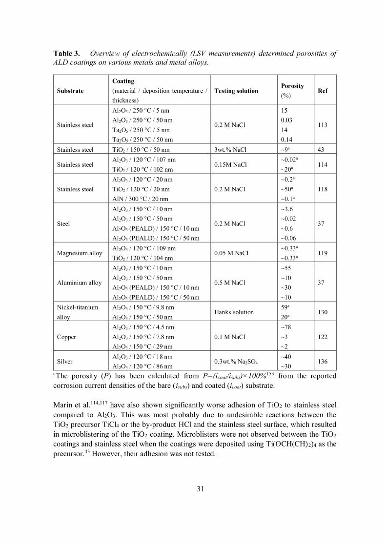
The sealing properties of Al2O3 have been found significantly better than those of TiO2,Ta2O5 and AlN in electrochemical tests (Table 3).26,113,114,117-119 For instance, on stainlesssteel the corrosion current density was decreased three orders of magnitude with a 50 nmAl2O3 coating.113 With TiO2 and Ta2O5, the corresponding decreases were only one andtwo orders of magnitude.43,113 This can be attributed to the intrinsically better insulatingproperties151,152 and better nucleation on challenging substrates of ALD Al2O3 comparedto the other materials.53 Furthermore, TiO2 and other materials that can be crystalline asdeposited suffer from the easier access of corrosives to the protected surface due to thegrain boundaries.26,48,118
31
Table 3. Overview of electrochemically (LSV measurements) determined porosities ofALD coatings on various metals and metal alloys.
SubstrateCoating(material / deposition temperature /thickness)
Testing solutionPorosity(%)
Ref
Stainless steel
Al2O3 / 250 °C / 5 nmAl2O3 / 250 °C / 50 nmTa2O5 / 250 °C / 5 nmTa2O5 / 250 °C / 50 nm
0.2 M NaCl
150.03140.14
113
Stainless steel TiO2 / 150 °C / 50 nm 3wt.% NaCl ~9a 43
Stainless steelAl2O3 / 120 °C / 107 nmTiO2 / 120 °C / 102 nm
0.15M NaCl~0.02a
~20a 114
Stainless steelAl2O3 / 120 °C / 20 nmTiO2 / 120 °C / 20 nmAlN / 300 °C / 20 nm
0.2 M NaCl~0.2a
~50a
~0.1a
118
Steel
Al2O3 / 150 °C / 10 nmAl2O3 / 150 °C / 50 nmAl2O3 (PEALD) / 150 °C / 10 nmAl2O3 (PEALD) / 150 °C / 50 nm
0.2 M NaCl
~3.6~0.02~0.6~0.06
37
Magnesium alloyAl2O3 / 120 °C / 109 nmTiO2 / 120 °C / 104 nm
0.05 M NaCl~0.33a
~0.33a 119
Aluminium alloy
Al2O3 / 150 °C / 10 nmAl2O3 / 150 °C / 50 nmAl2O3 (PEALD) / 150 °C / 10 nmAl2O3 (PEALD) / 150 °C / 50 nm
0.5 M NaCl
~55~10~30~10
37
Nickel-titaniumalloy
Al2O3 / 150 °C / 9.8 nmAl2O3 / 150 °C / 50 nm
Hanks´solution59a
20a 130
CopperAl2O3 / 150 °C / 4.5 nmAl2O3 / 150 °C / 7.8 nmAl2O3 / 150 °C / 29 nm
0.1 M NaCl~78~3~2
122
SilverAl2O3 / 120 °C / 18 nmAl2O3 / 120 °C / 86 nm
0.3wt.% Na2SO4~40~30
136
aThe porosity (P) has been calculated from P=(icoat/isubs)×100%153 from the reportedcorrosion current densities of the bare (isubs) and coated (icoat) substrate.
Marin et al.114,117 have also shown significantly worse adhesion of TiO2 to stainless steelcompared to Al2O3. This was most probably due to undesirable reactions between theTiO2 precursor TiCl4 or the by-product HCl and the stainless steel surface, which resultedin microblistering of the TiO2 coating. Microblisters were not observed between the TiO2
coatings and stainless steel when the coatings were deposited using Ti(OCH(CH)2)4 as theprecursor.43 However, their adhesion was not tested.
32
As already discussed in chapter 2.2.2.3, the main limitation of Al2O3 is the chemicalstability. Any problems observed with gaseous corrosives are expected to be morepronounced with the liquids, and thus the possible applications for protective ALD Al2O3
coatings are certainly restricted close to neutral solutions.35 Marin et al.118 have showncomplete stability of 20 nm Al2O3 on stainless steel for 2000 h immersion in 0.2 M NaClat pH 7. However, Abdulagatov et al.53 observed very severe corrosion of Al2O3 coatedevaporated copper film at 90 °C after 75 hours in water. Capping layers of ALD TiO2
were needed for sufficient durability, as will be elaborated below.
Compared to Al2O3, TiO2 coatings are expected to have better chemical durability. Materoet al.26 observed pitting of stainless steel samples coated with TiO2 during immersion in 1M HCl solution. However, the coatings themselves were found stable even in aggressiveH2SO4 solutions. Marin et al.118 showed changes in a 20 nm TiO2 coated stainless steel in0.2 M NaCl during the first 24 h of a 500 h immersion. After the first 24 h the system wasstabilised for the remaining duration of the test. This indicated slight reduction of theprotective properties of the TiO2 coatings, but no dissolution was observed. It can beconcluded that the chemical durability of ALD TiO2 would appear to be sufficient againsta range of aggressive chemicals, but it also contains pinhole defects endangering the long-term durability of the protected material.
Similar to TiO2, Ta2O5 is expected to be chemically more stable than Al2O3,35 andtherefore a possible alternative to TiO2. The Ta2O5 coatings deposited fromTa(OCH2CH3)5 and H2O are amorphous.8,26,113 Thus the problem of pinhole defectsformed at the grain boundaries of polycrystalline coatings is avoided. Unfortunately, thelong-term stability tests of Ta2O5 coatings on metal substrates are limited. Matero et al.26
showed that stainless steel coated with 150–300 nm Ta2O5 suffer from pitting corrosion in0.1 M HCl solutions. Slight solubility of Ta2O5 was indicated. On the other hand,Sammelselg et al.47 have shown that Ta2O5 on silicon is etched at a very low rate of <0.1nm/s in 80% H2SO4 solution at 110 °C.
Systematic electrochemical studies on corrosion protection properties of ALD SiO2
coatings on metals have not been done. The existing papers have been focused on provingthe viability of protection with ALD for specific applications.49,132-135 On Al-mirrors theSiO2 coatings were grown from [(CH3)3CO]3SiOH with Al(CH3)3 catalyst at 300 °C.49 Theprotection afforded by a 10 nm ALD coating was better than that achieved with 30 nm e-beam evaporated SiO2 and 100 nm commercial SiO2 coatings. The testing was done in 24wt.% KOH solutions. The protective properties further improved with increasing coatingthickness. Al mirrors coated with 120 nm SiO2 were shown to withstand 6 wt.%hydrochloric acid, 70 wt.% nitric acid, 40 wt.% sulphuric acid, 24 wt.% KOH, acetone,isopropanol and 0.77 M NaCl solutions for 2 hours without noticeable changes.
Adequate protection of the electrodes used in attaching and detaching proteins on surfaceswith nanonewton dielectrophoretic forces has been realised with 10 nm ALD SiO2.133-135
The electrolyte solution was deionised water. The coating was deposited from
33
tris(dimethylamino)silane ([(CH3)2N]3SiH) and O2 plasma at 200 °C. On stainless steelsubstrates aimed as biological implants 15 nm SiO2 coatings were electrochemicallydetermined to completely cover the surface.132 The SiO2 coatings were grown frombis(tertiarybutylamino)silane ([(CH3)3CNH]2SiH2) and O2 plasma at 300 °C. The testingwas done in 2mM Ru(NH3)6Cl3 - 0.1 M KCl solution. In both applications only theviability of using the protective ALD coating was demonstrated without additional workon optimizing the coating properties.
2.2.3.4 Multilayer and mixture coatings
Coatings combining two or more ALD grown materials have been used to protect stainlesssteel,19, 26, 114, 115, 117 silver and sterling silver,19,97,124 copper,19,53 magnesium alloy,19,119
cobalt alloy19 and aluminium alloy.19 The most common material combination is Al2O3
and TiO2: Al2O3 layers have been used to improve the adhesion/nucleation of thesubsequent TiO2 layer,53,124 and provide adequate sealing properties.53 TiO2 layers in turnhave been used to protect the chemically unstable Al2O3 from the environment thuspreventing its corrosion.53,138 Also nanolaminate and mixture coatings have been used tocombine the sealing properties of Al2O3 and chemical durability of TiO2 in more complexcoating systems.19,26,51,97,114,115,117,119,131
Nucleation of ALD Al2O3 from Al(CH3)3 and H2O is known to occur well on a variety ofsubstrate materials.22-25 Thus it can be used even as a very thin layer beneath other ALDmaterials to ensure good nucleation. Abdulagatov et al.53 studied in detail the nucleation ofAl2O3 and TiO2 on copper. While nucleation of Al2O3 was observed to occur in 15–20cycles, the TiO2 coatings had significant porosity still at 20 nm thicknesses and showedincreased roughnesses compared to the bare substrate implying an island-like growthmechanism. Sufficient corrosion protection properties were only observed with coatingsutilizing an Al2O3 nucleation layer beneath TiO2. Ultra-thin 0.2 nm Al2O3 layers have alsobeen shown to decrease the necessary thickness of an ALD TiO2 coating on plasmonicsilver nanoparticles in DSSCs from 7.7 to 5.8 nm.124
Abdulagatov et al.53 have shown that the durability of ALD Al2O3 on copper can beimproved with TiO2 capping (Figure 6). Al2O3 on copper lost its protective propertiesalmost immediately in H2O at 90 °C, but the ALD TiO2 capped Al2O3 protected thesubstrate for nearly 90 days.
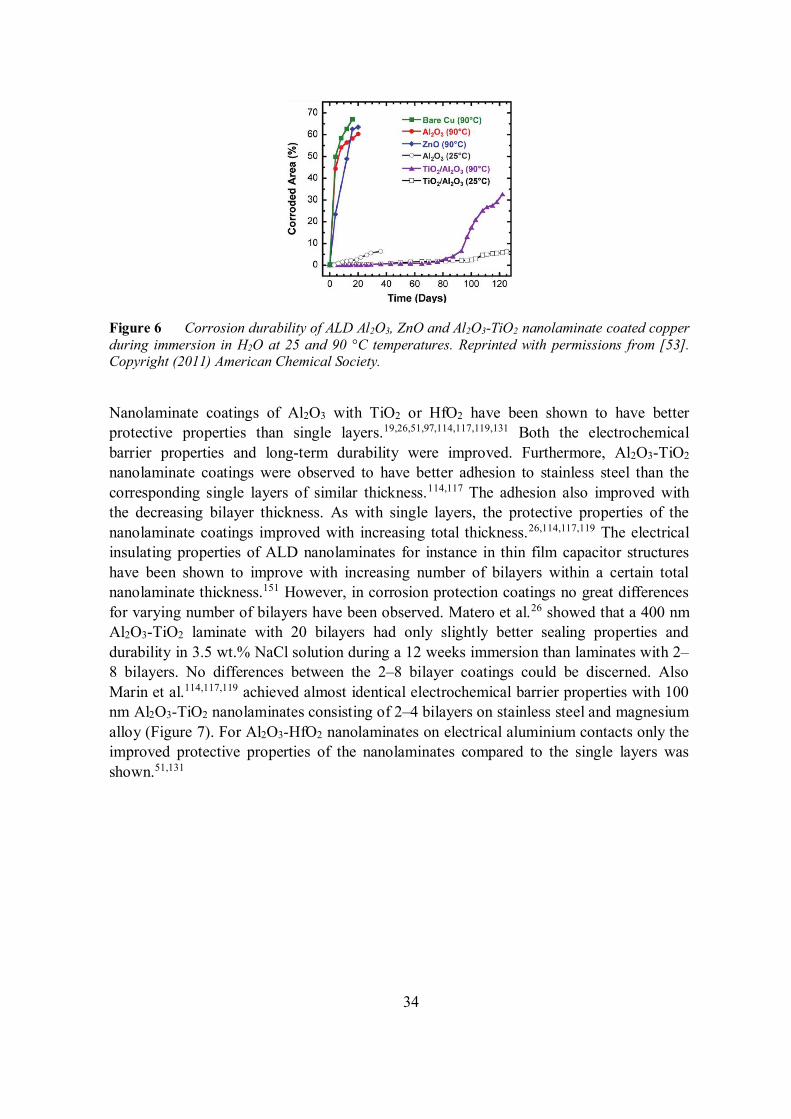
34
Figure 6 Corrosion durability of ALD Al2O3, ZnO and Al2O3-TiO2 nanolaminate coated copperduring immersion in H2O at 25 and 90 °C temperatures. Reprinted with permissions from [53].Copyright (2011) American Chemical Society.
Nanolaminate coatings of Al2O3 with TiO2 or HfO2 have been shown to have betterprotective properties than single layers.19,26,51,97,114,117,119,131 Both the electrochemicalbarrier properties and long-term durability were improved. Furthermore, Al2O3-TiO2
nanolaminate coatings were observed to have better adhesion to stainless steel than thecorresponding single layers of similar thickness.114,117 The adhesion also improved withthe decreasing bilayer thickness. As with single layers, the protective properties of thenanolaminate coatings improved with increasing total thickness.26,114,117,119 The electricalinsulating properties of ALD nanolaminates for instance in thin film capacitor structureshave been shown to improve with increasing number of bilayers within a certain totalnanolaminate thickness.151 However, in corrosion protection coatings no great differencesfor varying number of bilayers have been observed. Matero et al.26 showed that a 400 nmAl2O3-TiO2 laminate with 20 bilayers had only slightly better sealing properties anddurability in 3.5 wt.% NaCl solution during a 12 weeks immersion than laminates with 2–8 bilayers. No differences between the 2–8 bilayer coatings could be discerned. AlsoMarin et al.114,117,119 achieved almost identical electrochemical barrier properties with 100nm Al2O3-TiO2 nanolaminates consisting of 2–4 bilayers on stainless steel and magnesiumalloy (Figure 7). For Al2O3-HfO2 nanolaminates on electrical aluminium contacts only theimproved protective properties of the nanolaminates compared to the single layers wasshown.51,131
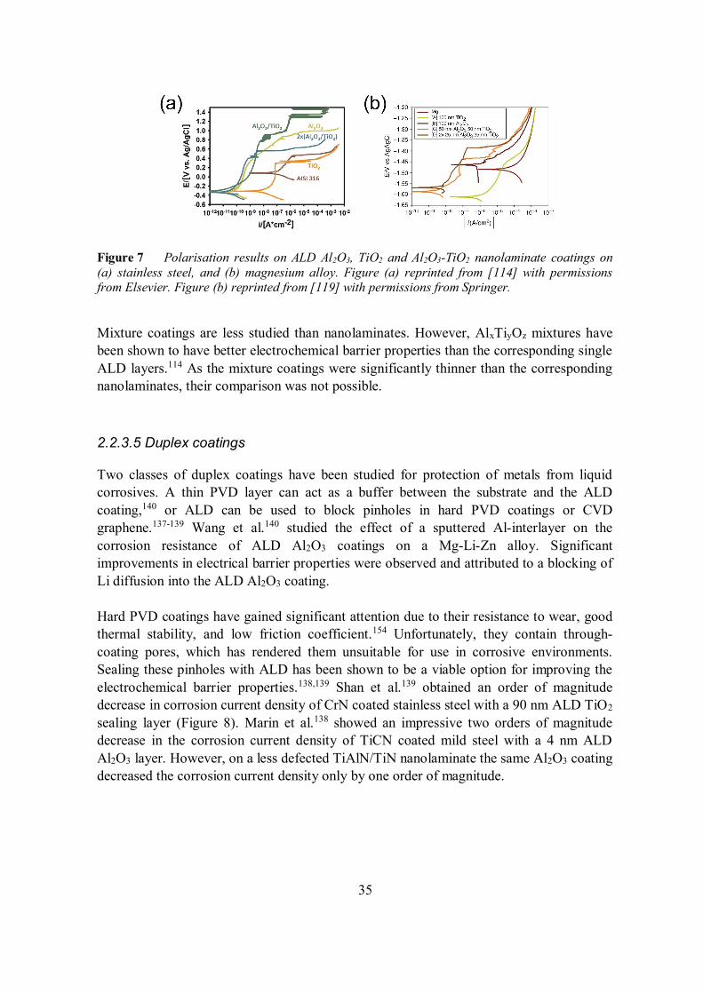
35
Figure 7 Polarisation results on ALD Al2O3, TiO2 and Al2O3-TiO2 nanolaminate coatings on(a) stainless steel, and (b) magnesium alloy. Figure (a) reprinted from [114] with permissionsfrom Elsevier. Figure (b) reprinted from [119] with permissions from Springer.
Mixture coatings are less studied than nanolaminates. However, AlxTiyOz mixtures havebeen shown to have better electrochemical barrier properties than the corresponding singleALD layers.114 As the mixture coatings were significantly thinner than the correspondingnanolaminates, their comparison was not possible.
2.2.3.5 Duplex coatings
Two classes of duplex coatings have been studied for protection of metals from liquidcorrosives. A thin PVD layer can act as a buffer between the substrate and the ALDcoating,140 or ALD can be used to block pinholes in hard PVD coatings or CVDgraphene.137-139 Wang et al.140 studied the effect of a sputtered Al-interlayer on thecorrosion resistance of ALD Al2O3 coatings on a Mg-Li-Zn alloy. Significantimprovements in electrical barrier properties were observed and attributed to a blocking ofLi diffusion into the ALD Al2O3 coating.
Hard PVD coatings have gained significant attention due to their resistance to wear, goodthermal stability, and low friction coefficient.154 Unfortunately, they contain through-coating pores, which has rendered them unsuitable for use in corrosive environments.Sealing these pinholes with ALD has been shown to be a viable option for improving theelectrochemical barrier properties.138,139 Shan et al.139 obtained an order of magnitudedecrease in corrosion current density of CrN coated stainless steel with a 90 nm ALD TiO2
sealing layer (Figure 8). Marin et al.138 showed an impressive two orders of magnitudedecrease in the corrosion current density of TiCN coated mild steel with a 4 nm ALDAl2O3 layer. However, on a less defected TiAlN/TiN nanolaminate the same Al2O3 coatingdecreased the corrosion current density only by one order of magnitude.
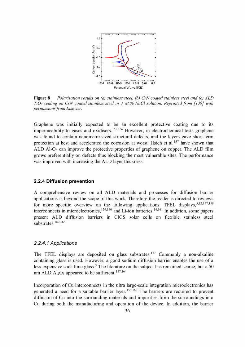
36
Figure 8 Polarisation results on (a) stainless steel, (b) CrN coated stainless steel and (c) ALDTiO2 sealing on CrN coated stainless steel in 3 wt.% NaCl solution. Reprinted from [139] withpermissions from Elsevier.
Graphene was initially expected to be an excellent protective coating due to itsimpermeability to gases and oxidisers.155,156 However, in electrochemical tests graphenewas found to contain nanometre-sized structural defects, and the layers gave short-termprotection at best and accelerated the corrosion at worst. Hsieh et al.137 have shown thatALD Al2O3 can improve the protective properties of graphene on copper. The ALD filmgrows preferentially on defects thus blocking the most vulnerable sites. The performancewas improved with increasing the ALD layer thickness.
2.2.4 Diffusion prevention
A comprehensive review on all ALD materials and processes for diffusion barrierapplications is beyond the scope of this work. Therefore the reader is directed to reviewsfor more specific overview on the following applications: TFEL displays,5,12,157,158
interconnects in microelectronics,159,160 and Li-ion batteries.14,161 In addition, some paperspresent ALD diffusion barriers in CIGS solar cells on flexible stainless steelsubstrates.162,163
2.2.4.1 Applications
The TFEL displays are deposited on glass substrates.157 Commonly a non-alkalinecontaining glass is used. However, a good sodium diffusion barrier enables the use of aless expensive soda lime glass.5 The literature on the subject has remained scarce, but a 50nm ALD Al2O3 appeared to be sufficient.157,164
Incorporation of Cu interconnects in the ultra large-scale integration microelectronics hasgenerated a need for a suitable barrier layer.159,160 The barriers are required to preventdiffusion of Cu into the surrounding materials and impurities from the surroundings intoCu during both the manufacturing and operation of the device. In addition, the barrier
37
should have excellent adhesion to Cu and the other surrounding materials, low resistivity,good electromigration and stress resistance, and preferentially amorphous ornanocrystalline structure to limit diffusion through voids, dislocations and grainboundaries. The deposition of the barrier should be done within the thermal budget (<400°C) of the back-end-of-line microelectronics processing. As ALD thin films are conformaland can be controlled down to sub-nanometre thicknesses, they are predicted to becomethe predominant solution in the future when the currently used PVD techniques reach theirlimits.165 The research on ALD barriers has been mainly focused on transition metalnitrides like TiN,56-58,61,66,166 TaN,54,55,62,64,66,167 WN,65,166 NbN,68 MoN67 and VN.69
However, also transition metal carbides,168 ternary materials like TaCN and WCN,169-173
oxides174-176 and metals177 have been considered. Also Ru containing mixtures andnanolaminates have been studied to enable direct electroplating of copper on the diffusionbarrier.178-183
In all-solid-state batteries one envisioned device architecture is based on 3D structure on asilicon substrate. To ensure stable long-term performance, the diffusion of Li out of theactive layers and into the substrate has to be prevented. The barrier layer should serve alsoas the current collector thus requiring good conductivity. From the ALD grown materialsthe main focus has been on TiN and TaN, but also Pt has been used.66,184-187
Chalcopyrite Cu(In,Ga)Se2 (CIGS) solar cells are made from thin films and thus have thedistinctive advantage over the traditional silicon wafer based solar cells that they can bemade flexible.188 However, to exploit this property also a flexible substrate is needed.Some device structures have been grown on polymers, but the thermal budget of polymersrestricts the conditions for depositing the active layers. Therefore metal foils have beenconsidered as an alternative. Stainless steel foils require a barrier layer for inhibiting out-diffusion of Fe, Ni, Cr, Mn and Mg, and an insulator to enable monolithic integration. Themost detrimental of the out-diffusing elements in regards of performance stability is Fe.189
ALD Al2O3 films have been considered as possible combined diffusion barriers andinsulators.162,163
2.2.2.4 Influence of deposition parameters
As for coatings against gaseous and liquid corrosives, the most important parametersaffecting the diffusion barrier properties of ALD thin films are the choice of precursors,54-
58,61,62,64,166,167 deposition temperature54,58,61,62,67,68,168,187 and film thickness.55,62,64,172,174-176
Because research in this area has been primarily application oriented, simply preventingdiffusion is not enough. The influences of deposition parameters to other film propertieshave to be additionally considered. In Cu interconnects and Li-ion batteries the filmresistivity is especially important.159,184 For instance, the pulse lengths,54,56,62,66,168,170,171,187
precursor sequence,54,58 and plasma power,66,171 have been shown to have an effect on thepurity and resistivity of ALD nitride barrier films.
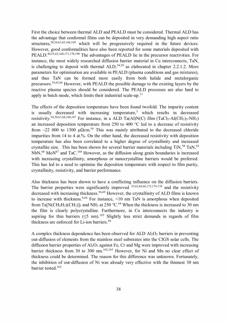
38
First the choice between thermal ALD and PEALD must be considered. Thermal ALD hasthe advantage that conformal films can be deposited in very demanding high aspect ratiostructures,20,54,61,65,166,169 which will be progressively required in the future devices.However, good conformalities have also been reported for some materials deposited withPEALD.40,55,62,168,171,178,190 The advantages of PEALD lie in the precursor reactivities. Forinstance, the most widely researched diffusion barrier material in Cu interconnects, TaN,is challenging to deposit with thermal ALD,54,59 as elaborated in chapter 2.2.1.2. Moreparameters for optimisation are available in PEALD (plasma conditions and gas mixtures),and thus TaN can be formed more easily from both halide and metalorganicprecursors.55,62,66 However, with PEALD the possible damage to the existing layers by thereactive plasma species should be considered. The PEALD processes are also hard toapply in batch mode, which limits their industrial scale-up.11
The effects of the deposition temperature have been found twofold. The impurity contentis usually decreased with increasing temperature,5 which results in decreasedresistivity.54,58,67,68,168,187 For instance, in a ALD Ta(Al)N(C) film (TaCl5-Al(CH3)3-NH3)an increased deposition temperature from 250 to 400 °C led to a decrease of resistivityfrom ~22 000 to 1300 cm.54 This was mainly attributed to the decreased chlorideimpurities from 14 to 4 at.%. On the other hand, the decreased resistivity with depositiontemperature has also been correlated to a higher degree of crystallinity and increasedcrystallite size. This has been shown for several barrier materials including TiN,58 TaN,54
NbN,68 MoN67 and TaC.168 However, as the diffusion along grain boundaries is increasedwith increasing crystallinity, amorphous or nanocrystalline barriers would be preferred.This has led to a need to optimise the deposition temperature with respect to film purity,crystallinity, resistivity, and barrier performance.
Also thickness has been shown to have a conflicting influence on the diffusion barriers.The barrier properties were significantly improved 55,62,64,66,172,174-176 and the resistivitydecreased with increasing thickness.56,69 However, the crystallinity of ALD films is knownto increase with thickness.8,64 For instance, <10 nm TaN is amorphous when depositedfrom Ta[N(CH2H3)(CH3)]5 and NH3 at 250 °C.64 When the thickness is increased to 30 nmthe film is clearly polycrystalline. Furthermore, in Cu interconnects the industry isaspiring for thin barriers ( 5 nm).165 Slightly less strict demands in regards of filmthickness are enforced for Li-ion barriers.66
A complex thickness dependence has been observed for ALD Al2O3 barriers in preventingout-diffusion of elements from the stainless steel substrates into the CIGS solar cells. Thediffusion barrier properties of Al2O3 against Fe, Cr and Mg were improved with increasingbarrier thickness from 30 to 300 nm.162,163 However, for Ni and Mn no clear effect ofthickness could be determined. The reason for this difference was unknown. Fortunately,the inhibition of out-diffusion of Ni was already very effective with the thinnest 30 nmbarrier tested.162
39
2.2.4.3 Comparison of barrier materials
The most actively studied materials for diffusion barriers for Cu in interconnects and Li-ions in batteries have been TiN and TaN.54-58,61,62,64,66,166,167 Both materials have highthermal stabilities, low bulk electrical resistivities and are stable in contact withCu.35,191,192 In regards of the Cu interconnects the barrier properties of TaN are usuallyreported to be slightly better than those of TiN (Table 4).54-58,61,62,64,66,166,167 This has beenattributed to the smaller crystallite size or even amorphous structure of TaN compared toTiN.54,55,57,62,64 Furthermore, the HCl by-product of the TiCl4-NH3 process has been shownto cause pitting corrosion on Cu thus making direct deposition of TiN on Cuchallenging.166 Unfortunately, ALD TaN films are not as easy as TiN to deposit with thedesired oxidation state (chapter 2.2.1.2.).59 Both TiN and TaN have been reported to havepoor adhesion to Cu.181,183
Table 4. Copper diffusion barrier performance of selected ALD materials.
ALD barrier(material / deposition temperature /thickness)
Resistivity( cm)
Testing(method / atmosphere / time)
Failuretemp.(°C)
Ref
TiN (ALD) / 450 °C / 36 nm 120 XRD / vacuum / 60 min 600 57Ti(Al)N (ALD) / 400 °C / 10 nm 140 XRD / N2 / 15 min 650 58TiN (PEALD) / 350 °C / 30 nm 200 XRD / vacuum / 30 min >700 66Ta(Al)N(C) (ALD) / 400 °C / 10nm
1300 XRD / N2 / 15 min 600 54
TaN (ALD) / 250 °C / 5 nm NA Sheet resistance / N2 / 30 min 600 64TaN (PEALD) / 225 °C / 30 nm 1550 XRD / vacuum / 30 min 600 66TaN (PEALD) / 250 °C / 2–15 nm 300–500 XRD / He / continuous heating 700–800 62WN (ALD) / 250–350 °C / 1.5 nm 1500–4000 SEM-RBS / H2-N2 / 30 min 600 65VN (PEALD) / 150 °C / 5 nm ~300 XRD / NA / continuous heating 720 69NbN (ALD) / 400 °C / 10 nm 750 XRD / N2 / 15 min 600 68MoN (ALD) / 400 °C / 10 nm 490 XRD / N2 / 15 min 650 67TaC (PEALD) / 300 °C / 5 nm 600 XRD / vacuum / 30 min 650 168WNC (ALD) / 313 °C / 12 nm 350 XRD / vacuum / 30 min 700 169TaCN (PEALD) / 200 °C / 5 nm 230 XRD / NA / 60 min 550 170Al2O3 (ALD) / 250 °C / 1–3 nm NA XRD / N2 / 5 min 675–750 175,
176TiO2 (ALD) / 240 °C / 1–3 nm NA XRD / N2 / 15 min 650-700 174Ta2O5 (ALD) / 240 / 1–4 nm NA XRD / N2 / 15 min 650 174HfO2 (ALD) / 250 / 1-3 nm NA XRD / N2 / 5 min 650–700 175,
176
Excellent results have been obtained with TiN in inhibiting Li-ion diffusion into thesilicon substrate in battery applications.66,184-187 Very little intercalation of Li into TiN wasobserved, and the samples remained stable during 50 galvanostatic cycles in a LiClO4 and
40
LiPF6 containing electrolyte. TaN has been found to be much more reactive towards Lithan TiN.66,186
Other potential diffusion barrier materials for Cu interconnects include several binarynitrides,65,67-69,166,173 TaC,168 WCN,169,172,173 TaCN,170,171 a few oxides174-176 and Ru.177
Similar to TiN and TaN, the other nitrides and carbides have been found to be relativelygood barriers (Table 4).65,67-69,168 However, they share some of the challenges observed forTiN and TaN. For instance, the HF formed in the ALD WN process from WF6 and NH3
has been found to etch Cu, Si and SiO2.166 Most of the materials are polycrystalline thusenabling diffusion along grain boundaries.67-69,166,168,173 The ternary WCN and TaCN seemto lack some issues related to the corresponding binary nitrides. No etching of Cu, Si orSiO2 has been observed for WNC deposited from WF6, NH3 and triethylboron,173 and thecarbon in TaCN has been shown to significantly decrease the resistivity.171 The oxideshave excellent barrier properties already at very low thicknesses (1–3 nm) (Table 4).174-176
Their insulating nature is suggested to become less significant when the diffusion barrierthickness diminishes. Ru is polycrystalline with columnar structure as deposited impedingits barrier properties.177 Furthermore, it has poor adhesion to Si and SiO2.181,183
Prevention of out-diffusion of elements from stainless steel into the active layers of aCIGS solar cell has only been studied for Al2O3 by ALD.162,163 Comparison of coatingmaterial properties is therefore impossible. With a 300 nm thick Al2O3, Fe diffusion couldbe decreased by 95 %. Furthermore, almost all Ni diffusion was inhibited already with a30 nm film. Unfortunately, significant Cr, Mn and Mg diffusion could be detected eventhrough a 300 nm film.
2.2.4.4 Multilayer and mixture coatings
Nanolaminates and mixtures have not been studied for prevention of diffusion in Li-ionbatteries or CIGS solar cells. The main objective in using complex structures in diffusionbarriers for Cu interconnects has been to allow direct electroplating of Cu onto thebarrier.178-181,183 Currently, PVD copper seed layers have to be deposited on the barrier forthe electroplating.62 This approach has the same challenge as PVD barriers: theconformality is not sufficient for the future devices. Direct electroplating of Cu on ALDRu has been shown,179,182 but the barrier properties of Ru are poor.177 Therefore, the workon laminates and mixtures as diffusion barriers for Cu interconnects has focused oncombining the direct electroplating properties of Ru with materials that have better barrierproperties. Some examples include Ru-TiN,183 Ru-TaN,181,182 Ru-WCN,178 Ru-TaCN180
and Ru-Al2O3.179 Because the nanolaminate or mixture structures disrupt the crystallites inthe films, the barrier properties have been shown to be even better than those observed forthe corresponding single layers. Also direct plating has been proven.178-180,193 Furthermore,as Ru has excellent adhesion to Cu and the nitrides have good adhesion to Si and SiO2, theadhesion issues encountered with the single layers could be simultaneously solved.181,183
41
Nanolaminates made of two materials with different sized crystallites can form coatingsthrough which the diffusion path is more tortuous, and thus improve the barrier properties.Limited research has been focused on simply inhibiting diffusion along grain boundarieswith nanolaminate structures, but this has been demonstrated with TiN-WN and TiN-WNC nanolaminates.173
2.2.5 Summary on protective ALD coatings
Coatings deposited by ALD have been studied for protection of metals, metal alloys andmetallic components in multimaterial structures against gaseous and liquid corrosives for anumber of applications. The application areas encompass for instance gas permeationbarriers, nanoparticles and nanostructures in general and in/on substrates for analyticaltools, DSSCs and heterogeneous catalysis, biomedical devices, prevention of tarnishing insilver jewels and historical artefacts, optical components and electrodes in Li-ion batteries,MCFCs and PECs for water splitting. In addition, there has been increasing activity infundamental research on the protection of metals and metal alloys in liquid corrosives.
The most common protective ALD coating material has been Al2O3. It has an almost idealALD process that enables deposition in a broad temperature range, excellent sealingproperties, and it has been shown to nucleate well on a variety of substrates. The mainchallenge with Al2O3 is the limited chemical stability. Some susceptibility has beenobserved even to water and water vapour. The other widely studied material for protectiveALD coatings has been TiO2. Unlike Al2O3, it is chemically stable. However, dependingon the deposition temperature, it has either a high impurity content or a polycrystallinestructure. Therefore, it also has limited sealing properties. The other studied protectiveALD materials include Ta2O5, SiO2, ZnO, ZrO2, HfO2, AlN and TiN. Best protectiveproperties have been achieved with coatings consisting of two or more materials instead ofsingle layers. These coatings enable combination of beneficial properties of two materialsinto a single coating and disrupt through-coating defects. The most effective, and studied,combination has been Al2O3 and TiO2. Al2O3 is used to ensure good nucleation andsealing properties, and TiO2 to gain chemical stability.
The main parameters affecting the protective performance of ALD coatings against bothgaseous and liquid corrosives have been shown to be the deposition temperature, thecoating thickness and the oxygen precursor. The quality of the coatings is improved withincreasing deposition temperature due to decreased impurity contents. However, withALD materials that can become deposited in polycrystalline form, careful optimisationshould be conducted between the purity and crystallinity of the coatings. Grain boundariesoffer an easy route to the protected surface. The purity and adhesion of ALD coatings havebeen shown to improve when a more aggressive oxygen precursor than H2O is used.However, care should be taken to ensure that the properties of the substrate are preserved.The protective properties of ALD coatings have been observed to significantly improvewith increasing thickness. This has been attributed to increased coverage, closure of
42
defects and decreased impurity content. Furthermore, in liquid corrosives the role of thesubstrate pre-treatment has been raised. Only a few studies have concentrated on the topic,but it would appear that at least decreasing substrate roughness and most probably alsoimproved cleanliness are beneficial.
Duplex coatings comprising of layers deposited by ALD and another method have beenstudied in protection against liquid corrosives. Two main goals have been focused on. Athin PVD layer has been used to separate the substrate and the ALD coating in order toprevent Li diffusion from the substrate to the protective layer. Also blocking of pinholes inPVD and graphene coatings with ALD has been considered.
ALD diffusion barriers have mainly been studied for Cu interconnects in microelectronics,but attention has also been given to Li-ions in batteries and diffusion of substrate speciesinto active layers in TFEL displays and CIGS solar cells. The most studied ALD diffusionbarriers for Cu interconnects and Li-ion batteries include nitrides like TiN and TaN,transition metal carbides, ternary materials like TaCN and WCN, oxides and metals.Generally similar dependencies with deposition parameters and single layers vs.multilayer and mixture structures were reported as for the corrosion protection coatings.However, the research was mostly focused on specific applications, and therefore alsoother material properties in addition to the diffusion barrier properties were critical. Forinhibiting diffusion of substrate species into active layers in TFEL and CIGS solar cells,ALD Al2O3 has been studied. Only few papers exist on the topics, and thus drawing clearconclusions is challenging. It would appear that already 30–50 nm Al2O3 can preventdiffusion of some metals, like Na and Fe. However, even 300 nm is not enough for somemetals, like Cr, Mn and Mg.
43
3 Experimental
A low alloy steel (AISI 52100, DIN 100Cr6) was used as the substrate. The steel wastempered at 180 °C and hardened to 805 HV hardness. The temperature range forprocessing the steel was limited to 160 °C for maintaining the mechanical properties. Thecomposition of the steel was in wt.% C (0.95-1.1), Cr (1.5), Ni (max. 0.30), Mn (0.25-0.45), Cu (max. 0.30), Si (0.15-0.35), P (max. 0.030), S (max. 0.025) and Fe (balance).
3.1 Pre-treatment of the substrate
Substrate surfaces were polished using two methods: lapping and brushing. All thesamples were first ground by planar grinding and then lapped. The lapping was conductedin a water based diamond suspension (6 m). Thereafter, mechanical brushing for 1 minwith Vitax polishing lathes (rotation speed 2800 rpm) using a Luxor polishing agent witha grain size of 0.1 m was conducted for the brushed samples. The surface conditioning isindicated separately for each sample.
After mechanical surface conditioning the samples were covered with silicone oil (Sigma-Aldrich GmbH, No. 85409) to prevent corrosion prior to applying the protective coating.Then the samples were packed in plastic boxes between two polyurethane membranes andshipped to another location for coating. At the coating location the samples weredegreased. Two degreasing recipes were used. In the short recipe the samples were wipedwith an acetone soaked precision wipe, ultrasonicated in isopropanol for 5 min, rinsedwith ethanol and blow-dried with compressed air. In the longer recipe the samples wereadditionally ultrasonicated in acetone for 5 min prior to ultrasonication in isopropanol.
Some of the samples were in situ or ex situ H2-Ar plasma pre-treated prior to coating withALD. The aim of the plasma pre-treatment was to more completely clean the samplesurface from organic residues. The pre-treatments were done with a Beneq TFS-200 ALDreactor presented in detail in reference [194]. The plasma was generated with acapacitively coupled rf power source at 13.56 MHz. The reactor was operated in remoteplasma configuration with a grid separating the active plasma from the substrate. Thepressure and temperature in the reactor were approximately 500 Pa and 160 °C. Theplasma gases, hydrogen (>99.999 %) and argon (>99.999 %), were purified on site withAeronex Gatekeeper and Entergris Gatekeeper purifiers prior to mixing in the reactor. Theshort pre-treatments (5 min) were conducted with a continuous plasma exposure and thelonger pre-treatments (30 min) with ALD-type pulsing to avoid excessive heating of thereaction chamber and samples. A sequence of 5 s on-pulse and 10 s off-pulse was repeateduntil the desired treatment time was reached. Between the in situ pre-treatment and theALD process the reaction chamber was purged for 15 min with nitrogen (>99.999 %). Theex situ treatment additionally involved cooling the reactor to 100 °C, venting to laboratoryair and moving the samples to another reactor for coating. The samples were exposed to
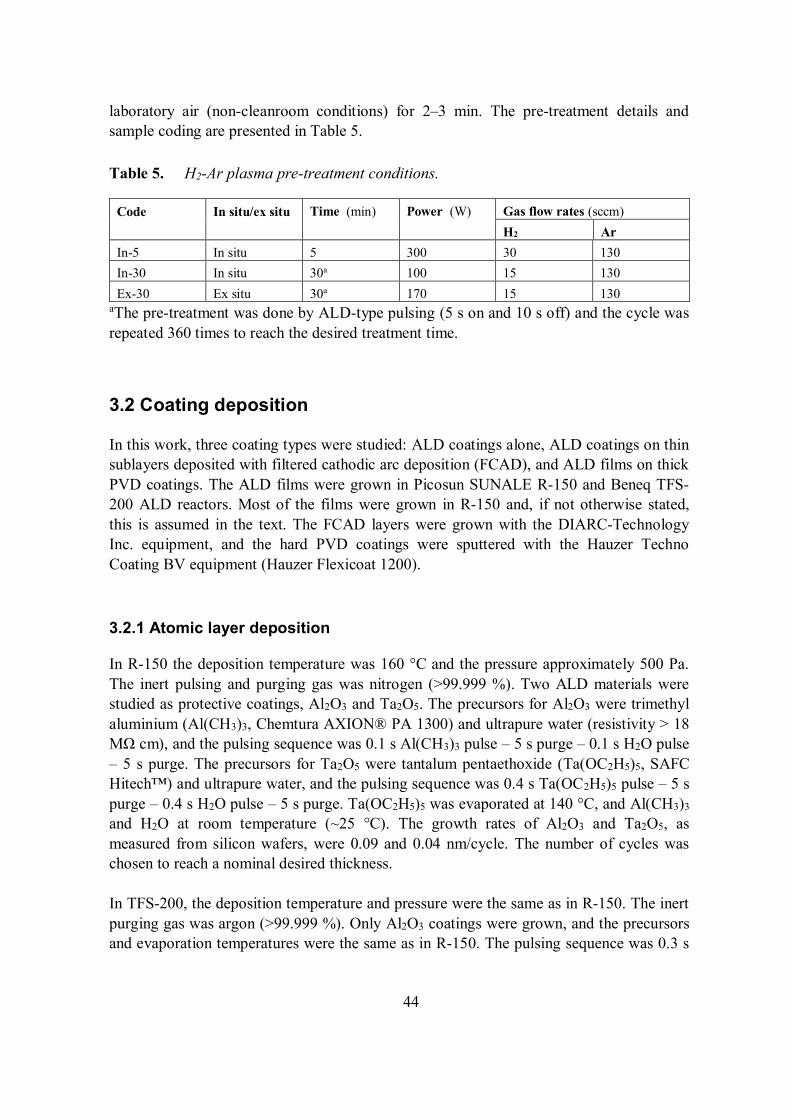
44
laboratory air (non-cleanroom conditions) for 2–3 min. The pre-treatment details andsample coding are presented in Table 5.
Table 5. H2-Ar plasma pre-treatment conditions.
Code In situ/ex situ Time (min) Power (W) Gas flow rates (sccm)H2 Ar
In-5 In situ 5 300 30 130In-30 In situ 30a 100 15 130Ex-30 Ex situ 30a 170 15 130
aThe pre-treatment was done by ALD-type pulsing (5 s on and 10 s off) and the cycle wasrepeated 360 times to reach the desired treatment time.
3.2 Coating deposition
In this work, three coating types were studied: ALD coatings alone, ALD coatings on thinsublayers deposited with filtered cathodic arc deposition (FCAD), and ALD films on thickPVD coatings. The ALD films were grown in Picosun SUNALE R-150 and Beneq TFS-200 ALD reactors. Most of the films were grown in R-150 and, if not otherwise stated,this is assumed in the text. The FCAD layers were grown with the DIARC-TechnologyInc. equipment, and the hard PVD coatings were sputtered with the Hauzer TechnoCoating BV equipment (Hauzer Flexicoat 1200).
3.2.1 Atomic layer deposition
In R-150 the deposition temperature was 160 °C and the pressure approximately 500 Pa.The inert pulsing and purging gas was nitrogen (>99.999 %). Two ALD materials werestudied as protective coatings, Al2O3 and Ta2O5. The precursors for Al2O3 were trimethylaluminium (Al(CH3)3, Chemtura AXION® PA 1300) and ultrapure water (resistivity > 18M cm), and the pulsing sequence was 0.1 s Al(CH3)3 pulse – 5 s purge – 0.1 s H2O pulse– 5 s purge. The precursors for Ta2O5 were tantalum pentaethoxide (Ta(OC2H5)5, SAFCHitech™) and ultrapure water, and the pulsing sequence was 0.4 s Ta(OC2H5)5 pulse – 5 spurge – 0.4 s H2O pulse – 5 s purge. Ta(OC2H5)5 was evaporated at 140 °C, and Al(CH3)3
and H2O at room temperature (~25 °C). The growth rates of Al2O3 and Ta2O5, asmeasured from silicon wafers, were 0.09 and 0.04 nm/cycle. The number of cycles waschosen to reach a nominal desired thickness.
In TFS-200, the deposition temperature and pressure were the same as in R-150. The inertpurging gas was argon (>99.999 %). Only Al2O3 coatings were grown, and the precursorsand evaporation temperatures were the same as in R-150. The pulsing sequence was 0.3 s
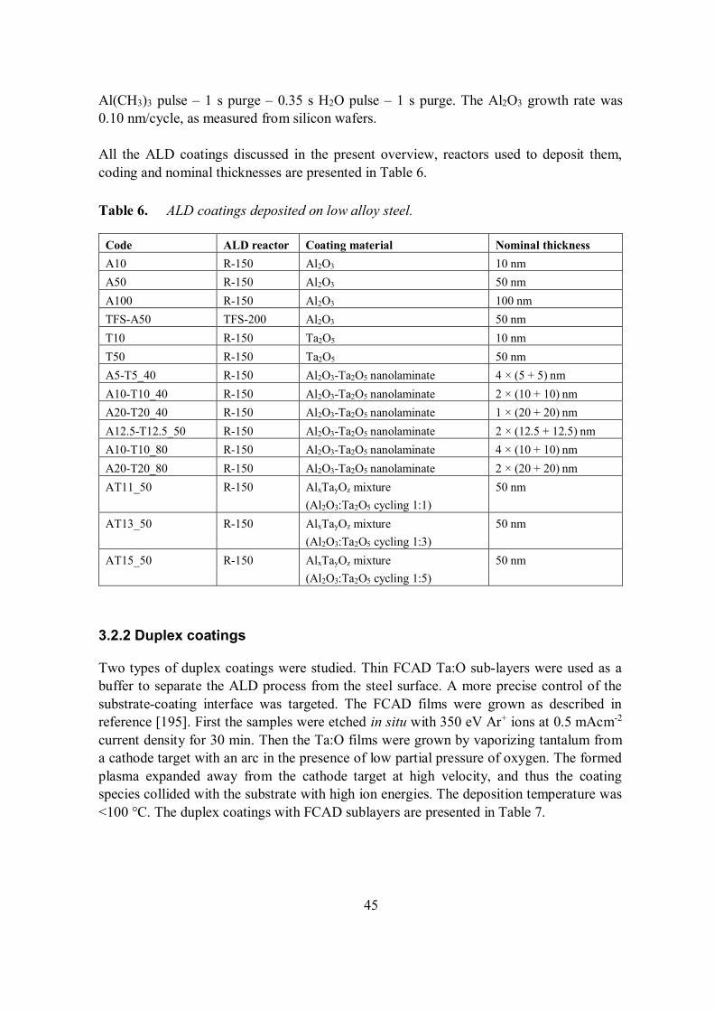
45
Al(CH3)3 pulse – 1 s purge – 0.35 s H2O pulse – 1 s purge. The Al2O3 growth rate was0.10 nm/cycle, as measured from silicon wafers.
All the ALD coatings discussed in the present overview, reactors used to deposit them,coding and nominal thicknesses are presented in Table 6.
Table 6. ALD coatings deposited on low alloy steel.
Code ALD reactor Coating material Nominal thicknessA10 R-150 Al2O3 10 nmA50 R-150 Al2O3 50 nmA100 R-150 Al2O3 100 nmTFS-A50 TFS-200 Al2O3 50 nmT10 R-150 Ta2O5 10 nmT50 R-150 Ta2O5 50 nmA5-T5_40 R-150 Al2O3-Ta2O5 nanolaminate 4 × (5 + 5) nmA10-T10_40 R-150 Al2O3-Ta2O5 nanolaminate 2 × (10 + 10) nmA20-T20_40 R-150 Al2O3-Ta2O5 nanolaminate 1 × (20 + 20) nmA12.5-T12.5_50 R-150 Al2O3-Ta2O5 nanolaminate 2 × (12.5 + 12.5) nmA10-T10_80 R-150 Al2O3-Ta2O5 nanolaminate 4 × (10 + 10) nmA20-T20_80 R-150 Al2O3-Ta2O5 nanolaminate 2 × (20 + 20) nmAT11_50 R-150 AlxTayOz mixture
(Al2O3:Ta2O5 cycling 1:1)50 nm
AT13_50 R-150 AlxTayOz mixture(Al2O3:Ta2O5 cycling 1:3)
50 nm
AT15_50 R-150 AlxTayOz mixture(Al2O3:Ta2O5 cycling 1:5)
50 nm
3.2.2 Duplex coatings
Two types of duplex coatings were studied. Thin FCAD Ta:O sub-layers were used as abuffer to separate the ALD process from the steel surface. A more precise control of thesubstrate-coating interface was targeted. The FCAD films were grown as described inreference [195]. First the samples were etched in situ with 350 eV Ar+ ions at 0.5 mAcm-2
current density for 30 min. Then the Ta:O films were grown by vaporizing tantalum froma cathode target with an arc in the presence of low partial pressure of oxygen. The formedplasma expanded away from the cathode target at high velocity, and thus the coatingspecies collided with the substrate with high ion energies. The deposition temperature was<100 °C. The duplex coatings with FCAD sublayers are presented in Table 7.
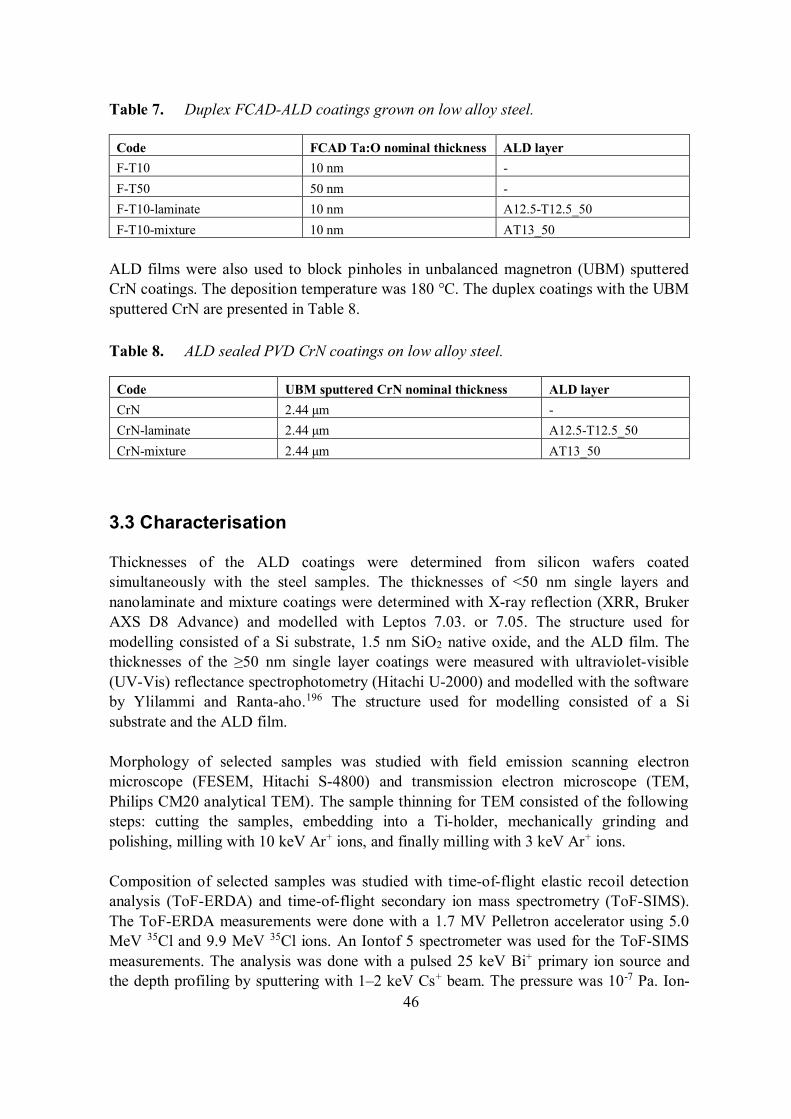
46
Table 7. Duplex FCAD-ALD coatings grown on low alloy steel.
Code FCAD Ta:O nominal thickness ALD layerF-T10 10 nm -F-T50 50 nm -F-T10-laminate 10 nm A12.5-T12.5_50F-T10-mixture 10 nm AT13_50
ALD films were also used to block pinholes in unbalanced magnetron (UBM) sputteredCrN coatings. The deposition temperature was 180 °C. The duplex coatings with the UBMsputtered CrN are presented in Table 8.
Table 8. ALD sealed PVD CrN coatings on low alloy steel.
Code UBM sputtered CrN nominal thickness ALD layerCrN 2.44 m -CrN-laminate 2.44 m A12.5-T12.5_50CrN-mixture 2.44 m AT13_50
3.3 Characterisation
Thicknesses of the ALD coatings were determined from silicon wafers coatedsimultaneously with the steel samples. The thicknesses of <50 nm single layers andnanolaminate and mixture coatings were determined with X-ray reflection (XRR, BrukerAXS D8 Advance) and modelled with Leptos 7.03. or 7.05. The structure used formodelling consisted of a Si substrate, 1.5 nm SiO2 native oxide, and the ALD film. Thethicknesses of the 50 nm single layer coatings were measured with ultraviolet-visible(UV-Vis) reflectance spectrophotometry (Hitachi U-2000) and modelled with the softwareby Ylilammi and Ranta-aho.196 The structure used for modelling consisted of a Sisubstrate and the ALD film.
Morphology of selected samples was studied with field emission scanning electronmicroscope (FESEM, Hitachi S-4800) and transmission electron microscope (TEM,Philips CM20 analytical TEM). The sample thinning for TEM consisted of the followingsteps: cutting the samples, embedding into a Ti-holder, mechanically grinding andpolishing, milling with 10 keV Ar+ ions, and finally milling with 3 keV Ar+ ions.
Composition of selected samples was studied with time-of-flight elastic recoil detectionanalysis (ToF-ERDA) and time-of-flight secondary ion mass spectrometry (ToF-SIMS).The ToF-ERDA measurements were done with a 1.7 MV Pelletron accelerator using 5.0MeV 35Cl and 9.9 MeV 35Cl ions. An Iontof 5 spectrometer was used for the ToF-SIMSmeasurements. The analysis was done with a pulsed 25 keV Bi+ primary ion source andthe depth profiling by sputtering with 1–2 keV Cs+ beam. The pressure was 10-7 Pa. Ion-
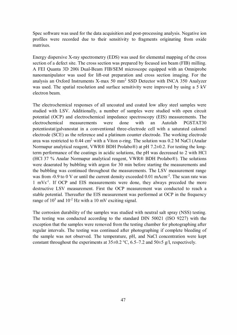
47
Spec software was used for the data acquisition and post-processing analysis. Negative ionprofiles were recorded due to their sensitivity to fragments originating from oxidematrixes.
Energy dispersive X-ray spectrometry (EDS) was used for elemental mapping of the crosssection of a defect site. The cross section was prepared by focused ion beam (FIB) milling.A FEI Quanta 3D 200i Dual-Beam FIB/SEM microscope equipped with an Omniprobenanomanipulator was used for lift-out preparation and cross section imaging. For theanalysis an Oxford Instruments X-max 50 mm2 SSD Detector with INCA 350 Analyzerwas used. The spatial resolution and surface sensitivity were improved by using a 5 kVelectron beam.
The electrochemical responses of all uncoated and coated low alloy steel samples werestudied with LSV. Additionally, a number of samples were studied with open circuitpotential (OCP) and electrochemical impedance spectroscopy (EIS) measurements. Theelectrochemical measurements were done with an Autolab PGSTAT30potentiostat/galvanostat in a conventional three-electrode cell with a saturated calomelelectrode (SCE) as the reference and a platinum counter electrode. The working electrodearea was restricted to 0.44 cm2 with a Viton o-ring. The solution was 0.2 M NaCl (AnalarNormapur analytical reagent, VWR® BDH Prolabo®) at pH 7.2±0.2. For testing the long-term performance of the coatings in acidic solutions, the pH was decreased to 2 with HCl(HCl 37 % Analar Normapur analytical reagent, VWR® BDH Prolabo®). The solutionswere deaerated by bubbling with argon for 30 min before starting the measurements andthe bubbling was continued throughout the measurements. The LSV measurement rangewas from -0.9 to 0 V or until the current density exceeded 0.01 mAcm-2. The scan rate was1 mVs-1. If OCP and EIS measurements were done, they always preceded the moredestructive LSV measurement. First the OCP measurement was conducted to reach astable potential. Thereafter the EIS measurement was performed at OCP in the frequencyrange of 105 and 10-2 Hz with a 10 mV exciting signal.
The corrosion durability of the samples was studied with neutral salt spray (NSS) testing.The testing was conducted according to the standard DIN 50021 (ISO 9227) with theexception that the samples were removed from the testing chamber for photographing afterregular intervals. The testing was continued after photographing if complete bleeding ofthe sample was not observed. The temperature, pH, and NaCl concentration were keptconstant throughout the experiments at 35±0.2 °C, 6.5–7.2 and 50±5 g/l, respectively.
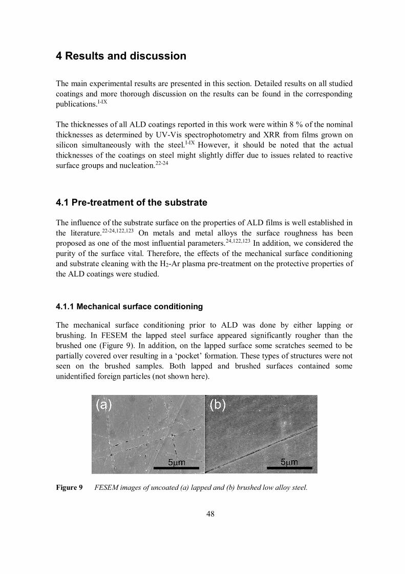
48
4 Results and discussion
The main experimental results are presented in this section. Detailed results on all studiedcoatings and more thorough discussion on the results can be found in the correspondingpublications.I-IX
The thicknesses of all ALD coatings reported in this work were within 8 % of the nominalthicknesses as determined by UV-Vis spectrophotometry and XRR from films grown onsilicon simultaneously with the steel.I-IX However, it should be noted that the actualthicknesses of the coatings on steel might slightly differ due to issues related to reactivesurface groups and nucleation.22-24
4.1 Pre-treatment of the substrate
The influence of the substrate surface on the properties of ALD films is well established inthe literature.22-24,122,123 On metals and metal alloys the surface roughness has beenproposed as one of the most influential parameters.24,122,123 In addition, we considered thepurity of the surface vital. Therefore, the effects of the mechanical surface conditioningand substrate cleaning with the H2-Ar plasma pre-treatment on the protective properties ofthe ALD coatings were studied.
4.1.1 Mechanical surface conditioning
The mechanical surface conditioning prior to ALD was done by either lapping orbrushing. In FESEM the lapped steel surface appeared significantly rougher than thebrushed one (Figure 9). In addition, on the lapped surface some scratches seemed to bepartially covered over resulting in a ‘pocket’ formation. These types of structures were notseen on the brushed samples. Both lapped and brushed surfaces contained someunidentified foreign particles (not shown here).
Figure 9 FESEM images of uncoated (a) lapped and (b) brushed low alloy steel.
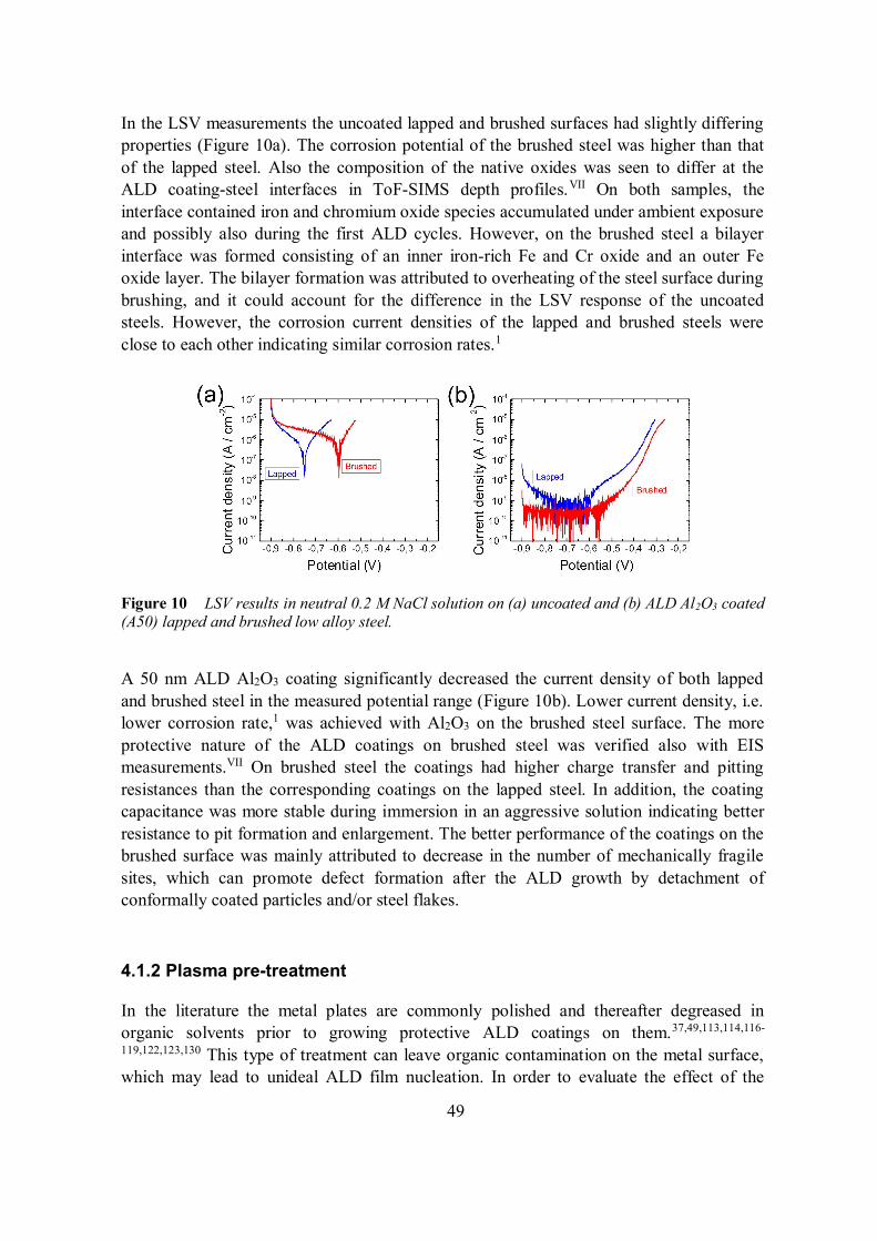
49
In the LSV measurements the uncoated lapped and brushed surfaces had slightly differingproperties (Figure 10a). The corrosion potential of the brushed steel was higher than thatof the lapped steel. Also the composition of the native oxides was seen to differ at theALD coating-steel interfaces in ToF-SIMS depth profiles.VII On both samples, theinterface contained iron and chromium oxide species accumulated under ambient exposureand possibly also during the first ALD cycles. However, on the brushed steel a bilayerinterface was formed consisting of an inner iron-rich Fe and Cr oxide and an outer Feoxide layer. The bilayer formation was attributed to overheating of the steel surface duringbrushing, and it could account for the difference in the LSV response of the uncoatedsteels. However, the corrosion current densities of the lapped and brushed steels wereclose to each other indicating similar corrosion rates.1
Figure 10 LSV results in neutral 0.2 M NaCl solution on (a) uncoated and (b) ALD Al2O3 coated(A50) lapped and brushed low alloy steel.
A 50 nm ALD Al2O3 coating significantly decreased the current density of both lappedand brushed steel in the measured potential range (Figure 10b). Lower current density, i.e.lower corrosion rate,1 was achieved with Al2O3 on the brushed steel surface. The moreprotective nature of the ALD coatings on brushed steel was verified also with EISmeasurements.VII On brushed steel the coatings had higher charge transfer and pittingresistances than the corresponding coatings on the lapped steel. In addition, the coatingcapacitance was more stable during immersion in an aggressive solution indicating betterresistance to pit formation and enlargement. The better performance of the coatings on thebrushed surface was mainly attributed to decrease in the number of mechanically fragilesites, which can promote defect formation after the ALD growth by detachment ofconformally coated particles and/or steel flakes.
4.1.2 Plasma pre-treatment
In the literature the metal plates are commonly polished and thereafter degreased inorganic solvents prior to growing protective ALD coatings on them.37,49,113,114,116-
119,122,123,130 This type of treatment can leave organic contamination on the metal surface,which may lead to unideal ALD film nucleation. In order to evaluate the effect of the
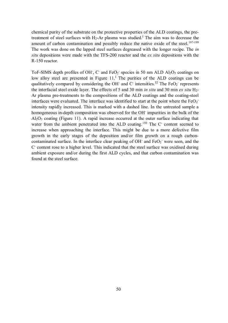
50
chemical purity of the substrate on the protective properties of the ALD coatings, the pre-treatment of steel surfaces with H2-Ar plasma was studied.I The aim was to decrease theamount of carbon contamination and possibly reduce the native oxide of the steel.197-199
The work was done on the lapped steel surfaces degreased with the longer recipe. The insitu depositions were made with the TFS-200 reactor and the ex situ depositions with theR-150 reactor.
ToF-SIMS depth profiles of OH-, C- and FeO2- species in 50 nm ALD Al2O3 coatings on
low alloy steel are presented in Figure 11.I The purities of the ALD coatings can bequalitatively compared by considering the OH- and C- intensities.32 The FeO2
- representsthe interfacial steel oxide layer. The effects of 5 and 30 min in situ and 30 min ex situ H2-Ar plasma pre-treatments to the compositions of the ALD coatings and the coating-steelinterfaces were evaluated. The interface was identified to start at the point where the FeO2
-
intensity rapidly increased. This is marked with a dashed line. In the untreated sample ahomogeneous in-depth composition was observed for the OH- impurities in the bulk of theAl2O3 coating (Figure 11). A rapid increase occurred at the outer surface indicating thatwater from the ambient penetrated into the ALD coating.150 The C- content seemed toincrease when approaching the interface. This might be due to a more defective filmgrowth in the early stages of the deposition and/or film growth on a rough carbon-contaminated surface. In the interface clear peaking of OH- and FeO2
- were seen, and theC- content rose to a higher level. This indicated that the steel surface was oxidised duringambient exposure and/or during the first ALD cycles, and that carbon contamination wasfound at the steel surface.
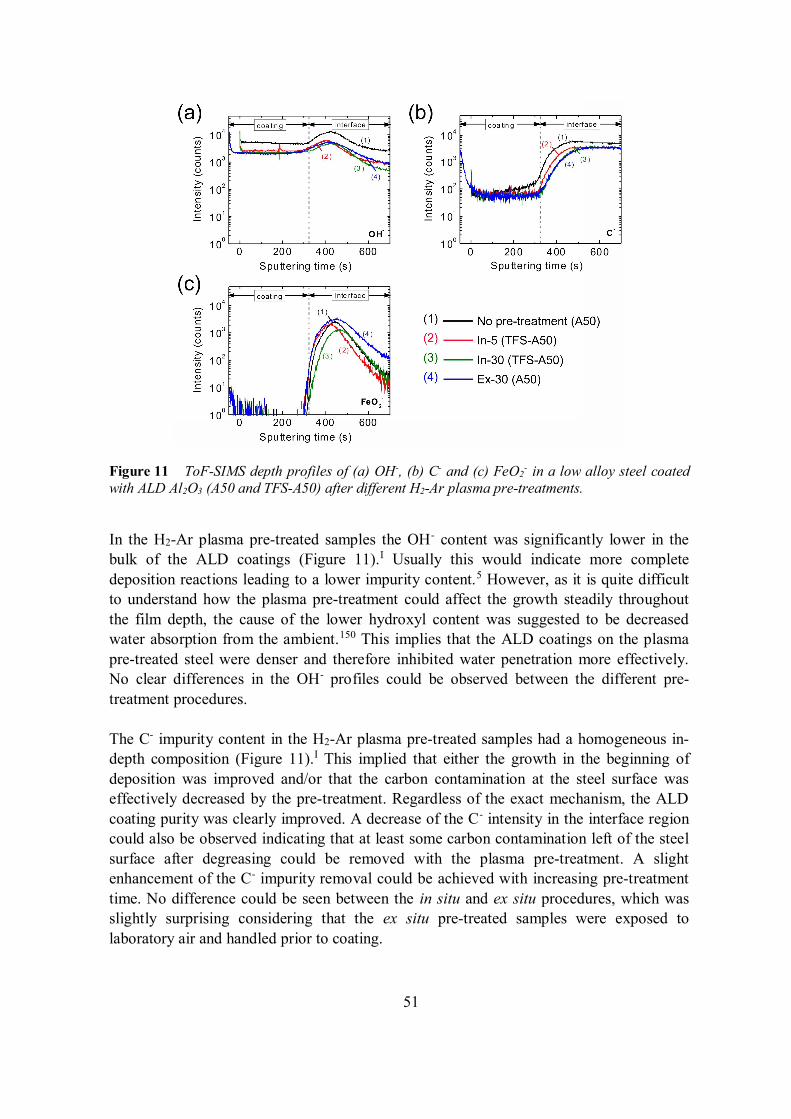
51
Figure 11 ToF-SIMS depth profiles of (a) OH-, (b) C- and (c) FeO2- in a low alloy steel coated
with ALD Al2O3 (A50 and TFS-A50) after different H2-Ar plasma pre-treatments.
In the H2-Ar plasma pre-treated samples the OH- content was significantly lower in thebulk of the ALD coatings (Figure 11).I Usually this would indicate more completedeposition reactions leading to a lower impurity content.5 However, as it is quite difficultto understand how the plasma pre-treatment could affect the growth steadily throughoutthe film depth, the cause of the lower hydroxyl content was suggested to be decreasedwater absorption from the ambient.150 This implies that the ALD coatings on the plasmapre-treated steel were denser and therefore inhibited water penetration more effectively.No clear differences in the OH- profiles could be observed between the different pre-treatment procedures.
The C- impurity content in the H2-Ar plasma pre-treated samples had a homogeneous in-depth composition (Figure 11).I This implied that either the growth in the beginning ofdeposition was improved and/or that the carbon contamination at the steel surface waseffectively decreased by the pre-treatment. Regardless of the exact mechanism, the ALDcoating purity was clearly improved. A decrease of the C- intensity in the interface regioncould also be observed indicating that at least some carbon contamination left of the steelsurface after degreasing could be removed with the plasma pre-treatment. A slightenhancement of the C- impurity removal could be achieved with increasing pre-treatmenttime. No difference could be seen between the in situ and ex situ procedures, which wasslightly surprising considering that the ex situ pre-treated samples were exposed tolaboratory air and handled prior to coating.
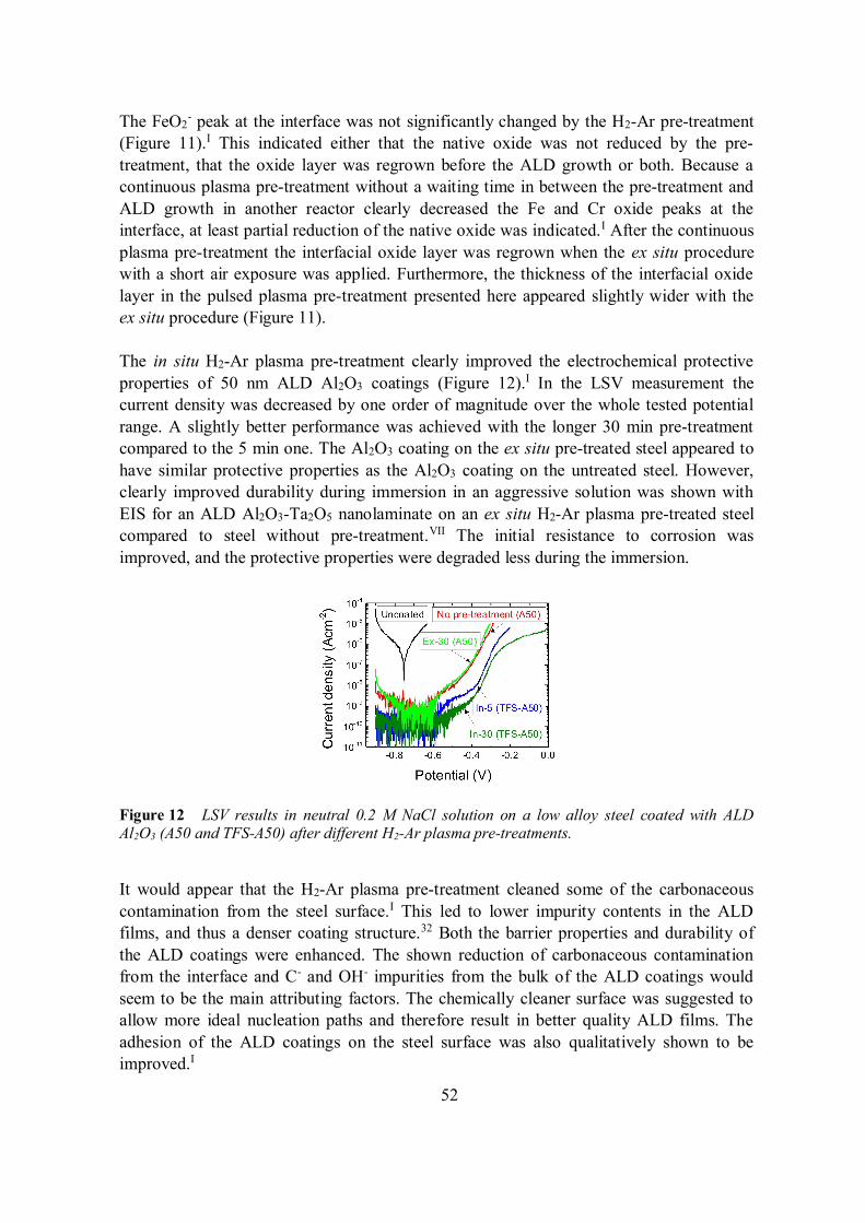
52
The FeO2- peak at the interface was not significantly changed by the H2-Ar pre-treatment
(Figure 11).I This indicated either that the native oxide was not reduced by the pre-treatment, that the oxide layer was regrown before the ALD growth or both. Because acontinuous plasma pre-treatment without a waiting time in between the pre-treatment andALD growth in another reactor clearly decreased the Fe and Cr oxide peaks at theinterface, at least partial reduction of the native oxide was indicated.I After the continuousplasma pre-treatment the interfacial oxide layer was regrown when the ex situ procedurewith a short air exposure was applied. Furthermore, the thickness of the interfacial oxidelayer in the pulsed plasma pre-treatment presented here appeared slightly wider with theex situ procedure (Figure 11).
The in situ H2-Ar plasma pre-treatment clearly improved the electrochemical protectiveproperties of 50 nm ALD Al2O3 coatings (Figure 12).I In the LSV measurement thecurrent density was decreased by one order of magnitude over the whole tested potentialrange. A slightly better performance was achieved with the longer 30 min pre-treatmentcompared to the 5 min one. The Al2O3 coating on the ex situ pre-treated steel appeared tohave similar protective properties as the Al2O3 coating on the untreated steel. However,clearly improved durability during immersion in an aggressive solution was shown withEIS for an ALD Al2O3-Ta2O5 nanolaminate on an ex situ H2-Ar plasma pre-treated steelcompared to steel without pre-treatment.VII The initial resistance to corrosion wasimproved, and the protective properties were degraded less during the immersion.
Figure 12 LSV results in neutral 0.2 M NaCl solution on a low alloy steel coated with ALDAl2O3 (A50 and TFS-A50) after different H2-Ar plasma pre-treatments.
It would appear that the H2-Ar plasma pre-treatment cleaned some of the carbonaceouscontamination from the steel surface.I This led to lower impurity contents in the ALDfilms, and thus a denser coating structure.32 Both the barrier properties and durability ofthe ALD coatings were enhanced. The shown reduction of carbonaceous contaminationfrom the interface and C- and OH- impurities from the bulk of the ALD coatings wouldseem to be the main attributing factors. The chemically cleaner surface was suggested toallow more ideal nucleation paths and therefore result in better quality ALD films. Theadhesion of the ALD coatings on the steel surface was also qualitatively shown to beimproved.I
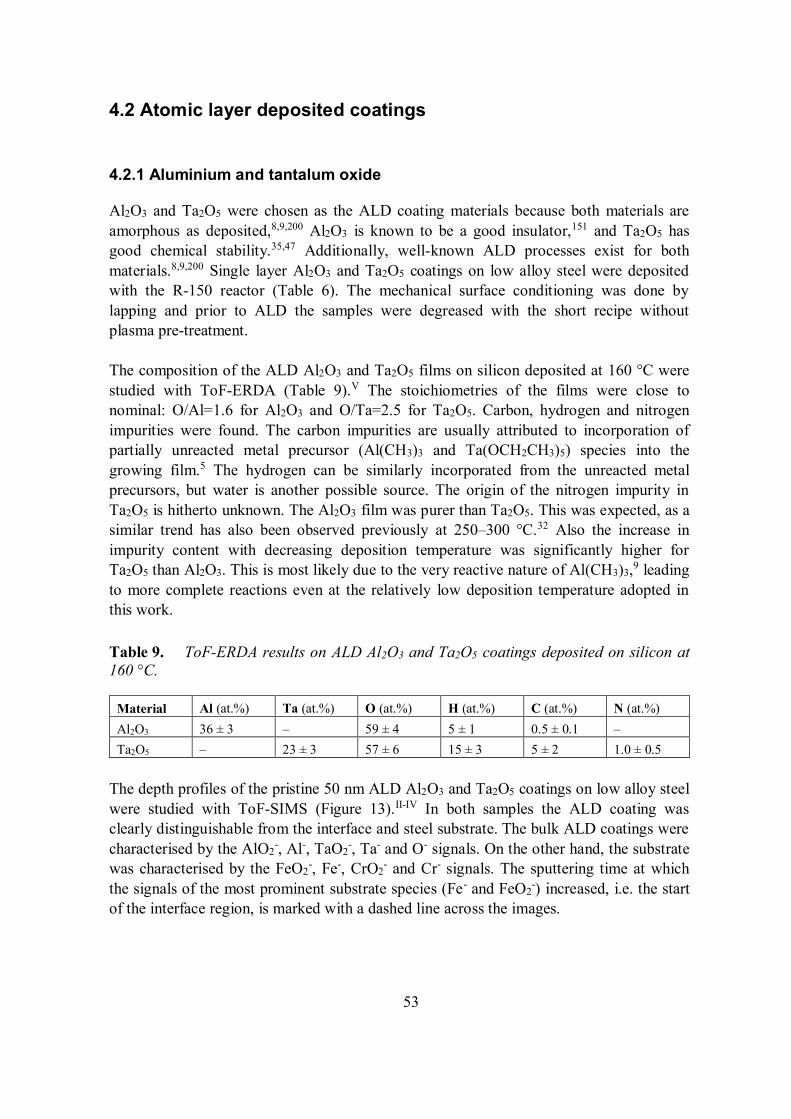
53
4.2 Atomic layer deposited coatings
4.2.1 Aluminium and tantalum oxide
Al2O3 and Ta2O5 were chosen as the ALD coating materials because both materials areamorphous as deposited,8,9,200 Al2O3 is known to be a good insulator,151 and Ta2O5 hasgood chemical stability.35,47 Additionally, well-known ALD processes exist for bothmaterials.8,9,200 Single layer Al2O3 and Ta2O5 coatings on low alloy steel were depositedwith the R-150 reactor (Table 6). The mechanical surface conditioning was done bylapping and prior to ALD the samples were degreased with the short recipe withoutplasma pre-treatment.
The composition of the ALD Al2O3 and Ta2O5 films on silicon deposited at 160 °C werestudied with ToF-ERDA (Table 9).V The stoichiometries of the films were close tonominal: O/Al=1.6 for Al2O3 and O/Ta=2.5 for Ta2O5. Carbon, hydrogen and nitrogenimpurities were found. The carbon impurities are usually attributed to incorporation ofpartially unreacted metal precursor (Al(CH3)3 and Ta(OCH2CH3)5) species into thegrowing film.5 The hydrogen can be similarly incorporated from the unreacted metalprecursors, but water is another possible source. The origin of the nitrogen impurity inTa2O5 is hitherto unknown. The Al2O3 film was purer than Ta2O5. This was expected, as asimilar trend has also been observed previously at 250–300 °C.32 Also the increase inimpurity content with decreasing deposition temperature was significantly higher forTa2O5 than Al2O3. This is most likely due to the very reactive nature of Al(CH3)3,9 leadingto more complete reactions even at the relatively low deposition temperature adopted inthis work.
Table 9. ToF-ERDA results on ALD Al2O3 and Ta2O5 coatings deposited on silicon at160 °C.
Material Al (at.%) Ta (at.%) O (at.%) H (at.%) C (at.%) N (at.%)Al2O3 36 ± 3 – 59 ± 4 5 ± 1 0.5 ± 0.1 –Ta2O5 – 23 ± 3 57 ± 6 15 ± 3 5 ± 2 1.0 ± 0.5
The depth profiles of the pristine 50 nm ALD Al2O3 and Ta2O5 coatings on low alloy steelwere studied with ToF-SIMS (Figure 13).II-IV In both samples the ALD coating wasclearly distinguishable from the interface and steel substrate. The bulk ALD coatings werecharacterised by the AlO2
-, Al-, TaO2-, Ta- and O- signals. On the other hand, the substrate
was characterised by the FeO2-, Fe-, CrO2
- and Cr- signals. The sputtering time at whichthe signals of the most prominent substrate species (Fe- and FeO2
-) increased, i.e. the startof the interface region, is marked with a dashed line across the images.
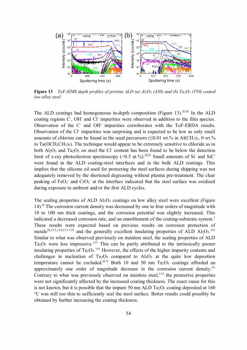
54
Figure 13 ToF-SIMS depth profiles of pristine ALD (a) Al2O3 (A50) and (b) Ta2O5 (T50) coatedlow alloy steel.
The ALD coatings had homogeneous in-depth composition (Figure 13).II-IV In the ALDcoating regions C-, OH- and Cl- impurities were observed in addition to the film species.Observation of the C- and OH- impurities corroborates with the ToF-ERDA results.Observation of the Cl- impurities was surprising and is expected to be low as only smallamounts of chlorine can be found in the used precursors ( 0.01 wt.% in Al(CH3)3, 0 wt.%in Ta(OCH2CH3)5). The technique would appear to be extremely sensitive to chloride as inboth Al2O3 and Ta2O5 on steel the Cl- content has been found to be below the detectionlimit of x-ray photoelectron spectroscopy (<0.5 at.%).II,IV Small amounts of Si- and SiC-
were found in the ALD coating-steel interfaces and in the bulk ALD coatings. Thisimplies that the silicone oil used for protecting the steel surfaces during shipping was notadequately removed by the shortened degreasing without plasma pre-treatment. The clearpeaking of FeO2
- and CrO2- at the interface indicated that the steel surface was oxidised
during exposure to ambient and/or the first ALD cycles.
The sealing properties of ALD Al2O3 coatings on low alloy steel were excellent (Figure14).II The corrosion current density was decreased by one to four orders of magnitude with10 to 100 nm thick coatings, and the corrosion potential was slightly increased. Thisindicated a decreased corrosion rate, and an ennoblement of the coating-substrate system.1
These results were expected based on previous results on corrosion protection ofmetals26,113,114,117-119 and the generally excellent insulating properties of ALD Al2O3.151
Similar to what was observed previously on stainless steel, the sealing properties of ALDTa2O5 were less impressive.113 This can be partly attributed to the intrinsically poorerinsulating properties of Ta2O5.151 However, the effects of the higher impurity contents andchallenges in nucleation of Ta2O5 compared to Al2O3 at the quite low depositiontemperature cannot be excluded.II-V Both 10 and 50 nm Ta2O5 coatings afforded anapproximately one order of magnitude decrease in the corrosion current density.IV
Contrary to what was previously observed on stainless steel,113 the protective propertieswere not significantly affected by the increased coating thickness. The exact cause for thisis not known, but it is possible that the impure 50 nm ALD Ta2O5 coating deposited at 160°C was still too thin to sufficiently seal the steel surface. Better results could possibly beobtained by further increasing the coating thickness.
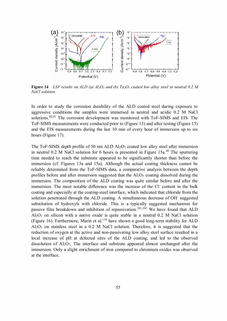
55
Figure 14 LSV results on ALD (a) Al2O3 and (b) Ta2O5 coated low alloy steel in neutral 0.2 MNaCl solution.
In order to study the corrosion durability of the ALD coated steel during exposure toaggressive conditions the samples were immersed in neutral and acidic 0.2 M NaClsolutions.III,IV The corrosion development was monitored with ToF-SIMS and EIS. TheToF-SIMS measurements were conducted prior to (Figure 13) and after testing (Figure 15)and the EIS measurements during the last 10 min of every hour of immersion up to sixhours (Figure 17).
The ToF-SIMS depth profile of 50 nm ALD Al2O3 coated low alloy steel after immersionin neutral 0.2 M NaCl solution for 6 hours is presented in Figure 15a.III The sputteringtime needed to reach the substrate appeared to be significantly shorter than before theimmersion (cf. Figures 13a and 15a). Although the actual coating thickness cannot bereliably determined from the ToF-SIMS data, a comparative analysis between the depthprofiles before and after immersion suggested that the Al2O3 coating dissolved during theimmersion. The composition of the ALD coating was quite similar before and after theimmersion. The most notable difference was the increase of the Cl- content in the bulkcoating and especially at the coating-steel interface, which indicated that chloride from thesolution penetrated through the ALD coating. A simultaneous decrease of OH- suggestedsubstitution of hydroxyls with chloride. This is a typically suggested mechanism forpassive film breakdown and inhibition of repassivation.201,202 We have found that ALDAl2O3 on silicon with a native oxide is quite stable in a neutral 0.2 M NaCl solution(Figure 16). Furthermore, Marin et al.118 have shown a good long-term stability for ALDAl2O3 on stainless steel in a 0.2 M NaCl solution. Therefore, it is suggested that thereduction of oxygen at the active and non-passivating low alloy steel surface resulted in alocal increase of pH at defected sites of the ALD coating, and led to the observeddissolution of Al2O3. The interface and substrate appeared almost unchanged after theimmersion. Only a slight enrichment of iron compared to chromium oxides was observedat the interface.
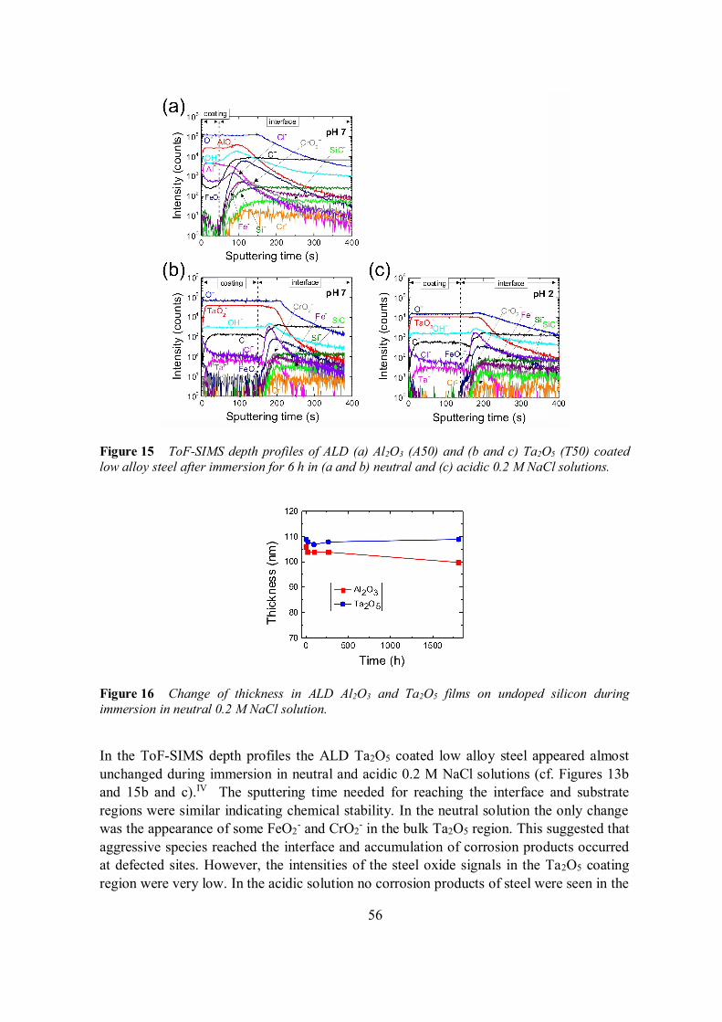
56
Figure 15 ToF-SIMS depth profiles of ALD (a) Al2O3 (A50) and (b and c) Ta2O5 (T50) coatedlow alloy steel after immersion for 6 h in (a and b) neutral and (c) acidic 0.2 M NaCl solutions.
Figure 16 Change of thickness in ALD Al2O3 and Ta2O5 films on undoped silicon duringimmersion in neutral 0.2 M NaCl solution.
In the ToF-SIMS depth profiles the ALD Ta2O5 coated low alloy steel appeared almostunchanged during immersion in neutral and acidic 0.2 M NaCl solutions (cf. Figures 13band 15b and c).IV The sputtering time needed for reaching the interface and substrateregions were similar indicating chemical stability. In the neutral solution the only changewas the appearance of some FeO2
- and CrO2- in the bulk Ta2O5 region. This suggested that
aggressive species reached the interface and accumulation of corrosion products occurredat defected sites. However, the intensities of the steel oxide signals in the Ta2O5 coatingregion were very low. In the acidic solution no corrosion products of steel were seen in the
57
Ta2O5 coating region, which suggested that any oxidised species were dissolved. Thisconclusion was supported by the fact that the interfacial region appeared to extend deeperinto the steel substrate implying an increased roughness due to active corrosion.
Bode plots of the EIS results measured during the immersion of the uncoated and ALDcoated low alloy steel samples are presented in Figure 17.III,IV The initial and changedprotective properties of the coatings and the corrosion process on the exposed steel surfacecan be quite specifically modelled from the EIS results with equivalent circuits. Details onthis type of analysis on the corrosion of Al2O3 and Ta2O5 coated steels is given inpublications [III] and [IV]. Here only the most prominent conclusions are presented.
In the beginning of the immersion in neutral 0.2 M NaCl solution the 50 nm ALD Al2O3
coating appeared to protect the steel very efficiently.III The global impedance was veryhigh as evidenced in the Bode plot by the low frequency range (Figures 17a). Furthermore,the capacitive range with phase angles nearly equal to 90° extended almost through thewhole measured frequency range, which is characteristic for good quality coatings.26 Theexcellent initial protective properties exhibited by the ALD Al2O3 coatings corroboratedthe results obtained in literature26,113,114,117-119 and with LSV (Figure 14). However, theBode plots changed drastically during immersion (Figure 17a). The global impedance atlow frequencies was decreased, and the phase angle at high and middle frequenciesdeviated from the capacitive response. These changes were attributed to decreased chargetransfer resistance (middle frequencies) and to decreased resistance against redox reactionsat the bottom of pinholes exposing the steel surface (high frequencies).203 The decrease ofcharge transfer resistance has been shown to correlate with increased porosity.II
Furthermore, the coating capacitance was increased, which indicated decreased coatingthickness. The decrease in coating thickness during immersion was also observed withToF-SIMS (Figure 15). Thus initially the ALD Al2O3 coating protected the steel well, butthe protective properties were rapidly decreased by both local and general dissolution ofthe coating. An average dissolution rate of 7 nm/h was calculated for ALD Al2O3 on lowalloy steel from the ToF-SIMS and EIS results.III
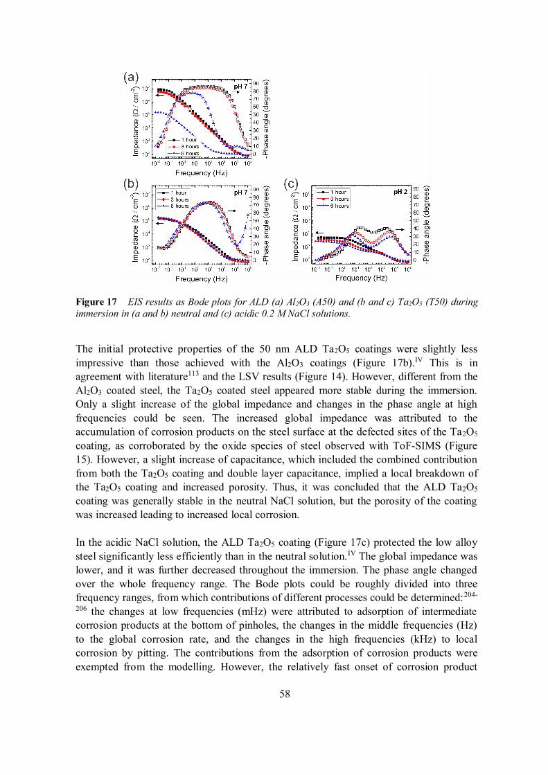
58
Figure 17 EIS results as Bode plots for ALD (a) Al2O3 (A50) and (b and c) Ta2O5 (T50) duringimmersion in (a and b) neutral and (c) acidic 0.2 M NaCl solutions.
The initial protective properties of the 50 nm ALD Ta2O5 coatings were slightly lessimpressive than those achieved with the Al2O3 coatings (Figure 17b).IV This is inagreement with literature113 and the LSV results (Figure 14). However, different from theAl2O3 coated steel, the Ta2O5 coated steel appeared more stable during the immersion.Only a slight increase of the global impedance and changes in the phase angle at highfrequencies could be seen. The increased global impedance was attributed to theaccumulation of corrosion products on the steel surface at the defected sites of the Ta2O5
coating, as corroborated by the oxide species of steel observed with ToF-SIMS (Figure15). However, a slight increase of capacitance, which included the combined contributionfrom both the Ta2O5 coating and double layer capacitance, implied a local breakdown ofthe Ta2O5 coating and increased porosity. Thus, it was concluded that the ALD Ta2O5
coating was generally stable in the neutral NaCl solution, but the porosity of the coatingwas increased leading to increased local corrosion.
In the acidic NaCl solution, the ALD Ta2O5 coating (Figure 17c) protected the low alloysteel significantly less efficiently than in the neutral solution.IV The global impedance waslower, and it was further decreased throughout the immersion. The phase angle changedover the whole frequency range. The Bode plots could be roughly divided into threefrequency ranges, from which contributions of different processes could be determined:204-
206 the changes at low frequencies (mHz) were attributed to adsorption of intermediatecorrosion products at the bottom of pinholes, the changes in the middle frequencies (Hz)to the global corrosion rate, and the changes in the high frequencies (kHz) to localcorrosion by pitting. The contributions from the adsorption of corrosion products wereexempted from the modelling. However, the relatively fast onset of corrosion product
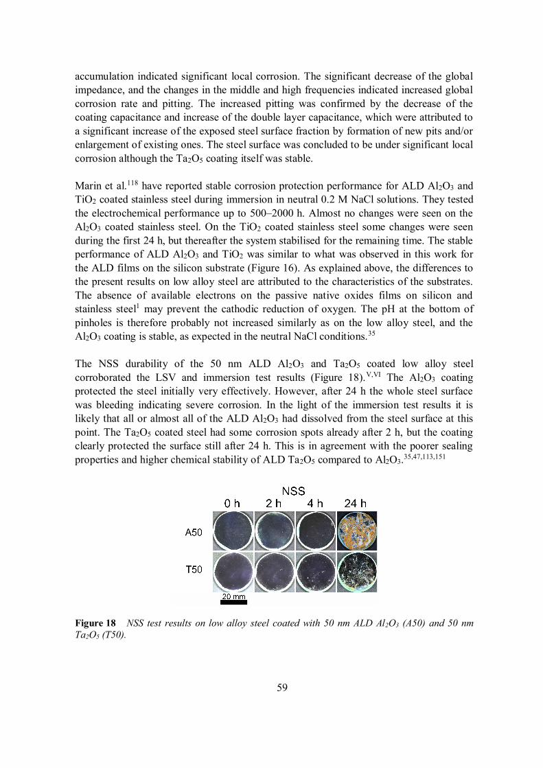
59
accumulation indicated significant local corrosion. The significant decrease of the globalimpedance, and the changes in the middle and high frequencies indicated increased globalcorrosion rate and pitting. The increased pitting was confirmed by the decrease of thecoating capacitance and increase of the double layer capacitance, which were attributed toa significant increase of the exposed steel surface fraction by formation of new pits and/orenlargement of existing ones. The steel surface was concluded to be under significant localcorrosion although the Ta2O5 coating itself was stable.
Marin et al.118 have reported stable corrosion protection performance for ALD Al2O3 andTiO2 coated stainless steel during immersion in neutral 0.2 M NaCl solutions. They testedthe electrochemical performance up to 500–2000 h. Almost no changes were seen on theAl2O3 coated stainless steel. On the TiO2 coated stainless steel some changes were seenduring the first 24 h, but thereafter the system stabilised for the remaining time. The stableperformance of ALD Al2O3 and TiO2 was similar to what was observed in this work forthe ALD films on the silicon substrate (Figure 16). As explained above, the differences tothe present results on low alloy steel are attributed to the characteristics of the substrates.The absence of available electrons on the passive native oxides films on silicon andstainless steel1 may prevent the cathodic reduction of oxygen. The pH at the bottom ofpinholes is therefore probably not increased similarly as on the low alloy steel, and theAl2O3 coating is stable, as expected in the neutral NaCl conditions.35
The NSS durability of the 50 nm ALD Al2O3 and Ta2O5 coated low alloy steelcorroborated the LSV and immersion test results (Figure 18).V,VI The Al2O3 coatingprotected the steel initially very effectively. However, after 24 h the whole steel surfacewas bleeding indicating severe corrosion. In the light of the immersion test results it islikely that all or almost all of the ALD Al2O3 had dissolved from the steel surface at thispoint. The Ta2O5 coated steel had some corrosion spots already after 2 h, but the coatingclearly protected the surface still after 24 h. This is in agreement with the poorer sealingproperties and higher chemical stability of ALD Ta2O5 compared to Al2O3.35,47,113,151
Figure 18 NSS test results on low alloy steel coated with 50 nm ALD Al2O3 (A50) and 50 nmTa2O5 (T50).
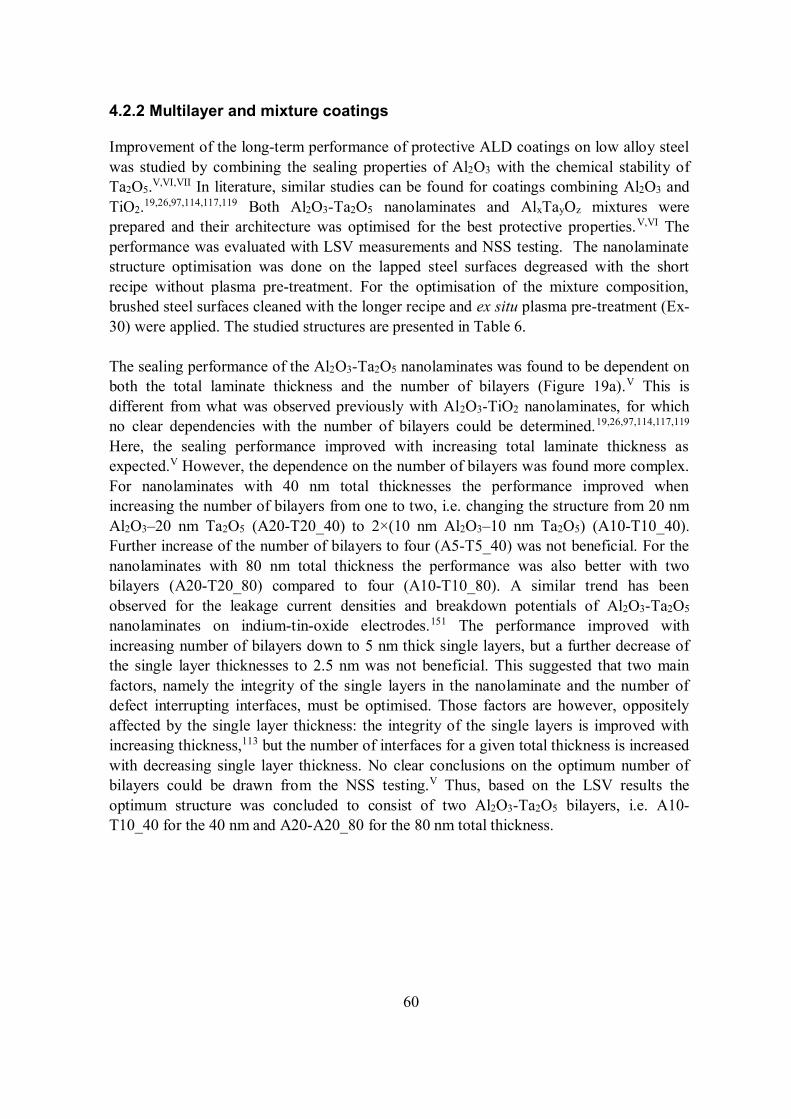
60
4.2.2 Multilayer and mixture coatings
Improvement of the long-term performance of protective ALD coatings on low alloy steelwas studied by combining the sealing properties of Al2O3 with the chemical stability ofTa2O5.V,VI,VII In literature, similar studies can be found for coatings combining Al2O3 andTiO2.19,26,97,114,117,119 Both Al2O3-Ta2O5 nanolaminates and AlxTayOz mixtures wereprepared and their architecture was optimised for the best protective properties.V,VI Theperformance was evaluated with LSV measurements and NSS testing. The nanolaminatestructure optimisation was done on the lapped steel surfaces degreased with the shortrecipe without plasma pre-treatment. For the optimisation of the mixture composition,brushed steel surfaces cleaned with the longer recipe and ex situ plasma pre-treatment (Ex-30) were applied. The studied structures are presented in Table 6.
The sealing performance of the Al2O3-Ta2O5 nanolaminates was found to be dependent onboth the total laminate thickness and the number of bilayers (Figure 19a).V This isdifferent from what was observed previously with Al2O3-TiO2 nanolaminates, for whichno clear dependencies with the number of bilayers could be determined.19,26,97,114,117,119
Here, the sealing performance improved with increasing total laminate thickness asexpected.V However, the dependence on the number of bilayers was found more complex.For nanolaminates with 40 nm total thicknesses the performance improved whenincreasing the number of bilayers from one to two, i.e. changing the structure from 20 nmAl2O3–20 nm Ta2O5 (A20-T20_40) to 2×(10 nm Al2O3–10 nm Ta2O5) (A10-T10_40).Further increase of the number of bilayers to four (A5-T5_40) was not beneficial. For thenanolaminates with 80 nm total thickness the performance was also better with twobilayers (A20-T20_80) compared to four (A10-T10_80). A similar trend has beenobserved for the leakage current densities and breakdown potentials of Al2O3-Ta2O5
nanolaminates on indium-tin-oxide electrodes.151 The performance improved withincreasing number of bilayers down to 5 nm thick single layers, but a further decrease ofthe single layer thicknesses to 2.5 nm was not beneficial. This suggested that two mainfactors, namely the integrity of the single layers in the nanolaminate and the number ofdefect interrupting interfaces, must be optimised. Those factors are however, oppositelyaffected by the single layer thickness: the integrity of the single layers is improved withincreasing thickness,113 but the number of interfaces for a given total thickness is increasedwith decreasing single layer thickness. No clear conclusions on the optimum number ofbilayers could be drawn from the NSS testing.V Thus, based on the LSV results theoptimum structure was concluded to consist of two Al2O3-Ta2O5 bilayers, i.e. A10-T10_40 for the 40 nm and A20-A20_80 for the 80 nm total thickness.
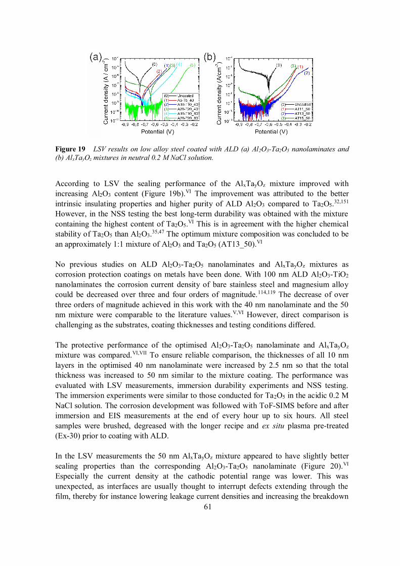
61
Figure 19 LSV results on low alloy steel coated with ALD (a) Al2O3-Ta2O5 nanolaminates and(b) AlxTayOz mixtures in neutral 0.2 M NaCl solution.
According to LSV the sealing performance of the AlxTayOz mixture improved withincreasing Al2O3 content (Figure 19b).VI The improvement was attributed to the betterintrinsic insulating properties and higher purity of ALD Al2O3 compared to Ta2O5.32,151
However, in the NSS testing the best long-term durability was obtained with the mixturecontaining the highest content of Ta2O5.VI This is in agreement with the higher chemicalstability of Ta2O5 than Al2O3.35,47 The optimum mixture composition was concluded to bean approximately 1:1 mixture of Al2O3 and Ta2O5 (AT13_50).VI
No previous studies on ALD Al2O3-Ta2O5 nanolaminates and AlxTayOz mixtures ascorrosion protection coatings on metals have been done. With 100 nm ALD Al2O3-TiO2
nanolaminates the corrosion current density of bare stainless steel and magnesium alloycould be decreased over three and four orders of magnitude.114,119 The decrease of overthree orders of magnitude achieved in this work with the 40 nm nanolaminate and the 50nm mixture were comparable to the literature values.V,VI However, direct comparison ischallenging as the substrates, coating thicknesses and testing conditions differed.
The protective performance of the optimised Al2O3-Ta2O5 nanolaminate and AlxTayOz
mixture was compared.VI,VII To ensure reliable comparison, the thicknesses of all 10 nmlayers in the optimised 40 nm nanolaminate were increased by 2.5 nm so that the totalthickness was increased to 50 nm similar to the mixture coating. The performance wasevaluated with LSV measurements, immersion durability experiments and NSS testing.The immersion experiments were similar to those conducted for Ta2O5 in the acidic 0.2 MNaCl solution. The corrosion development was followed with ToF-SIMS before and afterimmersion and EIS measurements at the end of every hour up to six hours. All steelsamples were brushed, degreased with the longer recipe and ex situ plasma pre-treated(Ex-30) prior to coating with ALD.
In the LSV measurements the 50 nm AlxTayOz mixture appeared to have slightly bettersealing properties than the corresponding Al2O3-Ta2O5 nanolaminate (Figure 20).VI
Especially the current density at the cathodic potential range was lower. This wasunexpected, as interfaces are usually thought to interrupt defects extending through thefilm, thereby for instance lowering leakage current densities and increasing the breakdown
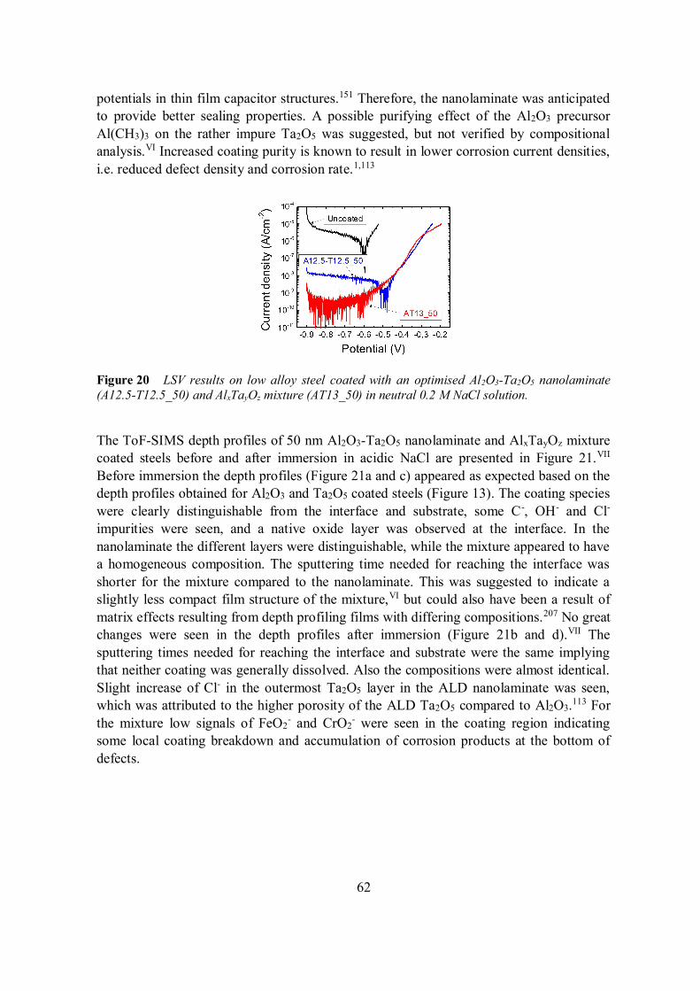
62
potentials in thin film capacitor structures.151 Therefore, the nanolaminate was anticipatedto provide better sealing properties. A possible purifying effect of the Al2O3 precursorAl(CH3)3 on the rather impure Ta2O5 was suggested, but not verified by compositionalanalysis.VI Increased coating purity is known to result in lower corrosion current densities,i.e. reduced defect density and corrosion rate.1,113
Figure 20 LSV results on low alloy steel coated with an optimised Al2O3-Ta2O5 nanolaminate(A12.5-T12.5_50) and AlxTayOz mixture (AT13_50) in neutral 0.2 M NaCl solution.
The ToF-SIMS depth profiles of 50 nm Al2O3-Ta2O5 nanolaminate and AlxTayOz mixturecoated steels before and after immersion in acidic NaCl are presented in Figure 21.VII
Before immersion the depth profiles (Figure 21a and c) appeared as expected based on thedepth profiles obtained for Al2O3 and Ta2O5 coated steels (Figure 13). The coating specieswere clearly distinguishable from the interface and substrate, some C-, OH- and Cl-impurities were seen, and a native oxide layer was observed at the interface. In thenanolaminate the different layers were distinguishable, while the mixture appeared to havea homogeneous composition. The sputtering time needed for reaching the interface wasshorter for the mixture compared to the nanolaminate. This was suggested to indicate aslightly less compact film structure of the mixture,VI but could also have been a result ofmatrix effects resulting from depth profiling films with differing compositions.207 No greatchanges were seen in the depth profiles after immersion (Figure 21b and d).VII Thesputtering times needed for reaching the interface and substrate were the same implyingthat neither coating was generally dissolved. Also the compositions were almost identical.Slight increase of Cl- in the outermost Ta2O5 layer in the ALD nanolaminate was seen,which was attributed to the higher porosity of the ALD Ta2O5 compared to Al2O3.113 Forthe mixture low signals of FeO2
- and CrO2- were seen in the coating region indicating
some local coating breakdown and accumulation of corrosion products at the bottom ofdefects.
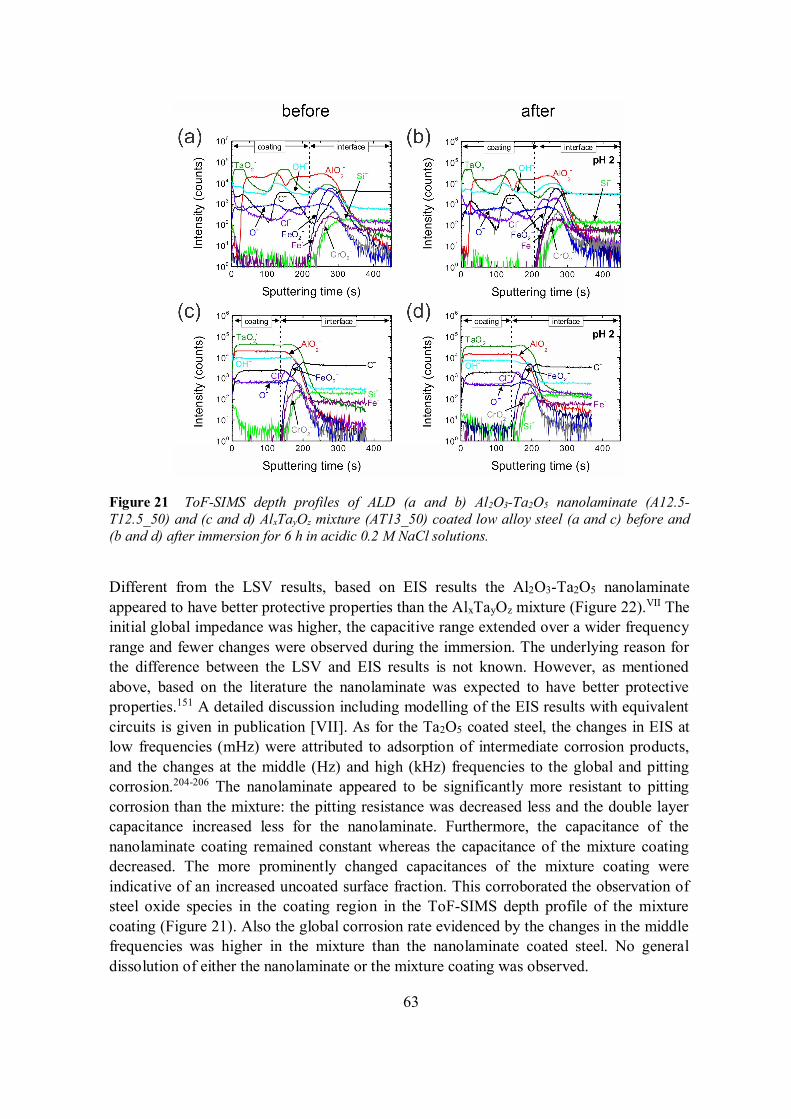
63
Figure 21 ToF-SIMS depth profiles of ALD (a and b) Al2O3-Ta2O5 nanolaminate (A12.5-T12.5_50) and (c and d) AlxTayOz mixture (AT13_50) coated low alloy steel (a and c) before and(b and d) after immersion for 6 h in acidic 0.2 M NaCl solutions.
Different from the LSV results, based on EIS results the Al2O3-Ta2O5 nanolaminateappeared to have better protective properties than the AlxTayOz mixture (Figure 22).VII Theinitial global impedance was higher, the capacitive range extended over a wider frequencyrange and fewer changes were observed during the immersion. The underlying reason forthe difference between the LSV and EIS results is not known. However, as mentionedabove, based on the literature the nanolaminate was expected to have better protectiveproperties.151 A detailed discussion including modelling of the EIS results with equivalentcircuits is given in publication [VII]. As for the Ta2O5 coated steel, the changes in EIS atlow frequencies (mHz) were attributed to adsorption of intermediate corrosion products,and the changes at the middle (Hz) and high (kHz) frequencies to the global and pittingcorrosion.204-206 The nanolaminate appeared to be significantly more resistant to pittingcorrosion than the mixture: the pitting resistance was decreased less and the double layercapacitance increased less for the nanolaminate. Furthermore, the capacitance of thenanolaminate coating remained constant whereas the capacitance of the mixture coatingdecreased. The more prominently changed capacitances of the mixture coating wereindicative of an increased uncoated surface fraction. This corroborated the observation ofsteel oxide species in the coating region in the ToF-SIMS depth profile of the mixturecoating (Figure 21). Also the global corrosion rate evidenced by the changes in the middlefrequencies was higher in the mixture than the nanolaminate coated steel. No generaldissolution of either the nanolaminate or the mixture coating was observed.
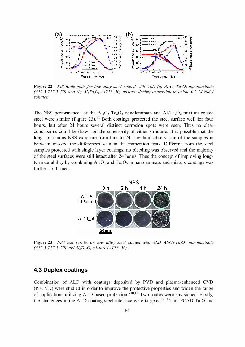
64
Figure 22 EIS Bode plots for low alloy steel coated with ALD (a) Al2O3-Ta2O5 nanolaminate(A12.5-T12.5_50) and (b) AlxTayOz (AT13_50) mixture during immersion in acidic 0.2 M NaClsolution.
The NSS performances of the Al2O3-Ta2O5 nanolaminate and AlxTayOz mixture coatedsteel were similar (Figure 23).VI Both coatings protected the steel surface well for fourhours, but after 24 hours several distinct corrosion spots were seen. Thus no clearconclusions could be drawn on the superiority of either structure. It is possible that thelong continuous NSS exposure from four to 24 h without observation of the samples inbetween masked the differences seen in the immersion tests. Different from the steelsamples protected with single layer coatings, no bleeding was observed and the majorityof the steel surfaces were still intact after 24 hours. Thus the concept of improving long-term durability by combining Al2O3 and Ta2O5 in nanolaminate and mixture coatings wasfurther confirmed.
Figure 23 NSS test results on low alloy steel coated with ALD Al2O3-Ta2O5 nanolaminate(A12.5-T12.5_50) and AlxTayOz mixture (AT13_50).
4.3 Duplex coatings
Combination of ALD with coatings deposited by PVD and plasma-enhanced CVD(PECVD) were studied in order to improve the protective properties and widen the rangeof applications utilizing ALD based protection.VIII,IX Two routes were envisioned. Firstly,the challenges in the ALD coating-steel interface were targeted.VIII Thin FCAD Ta:O and
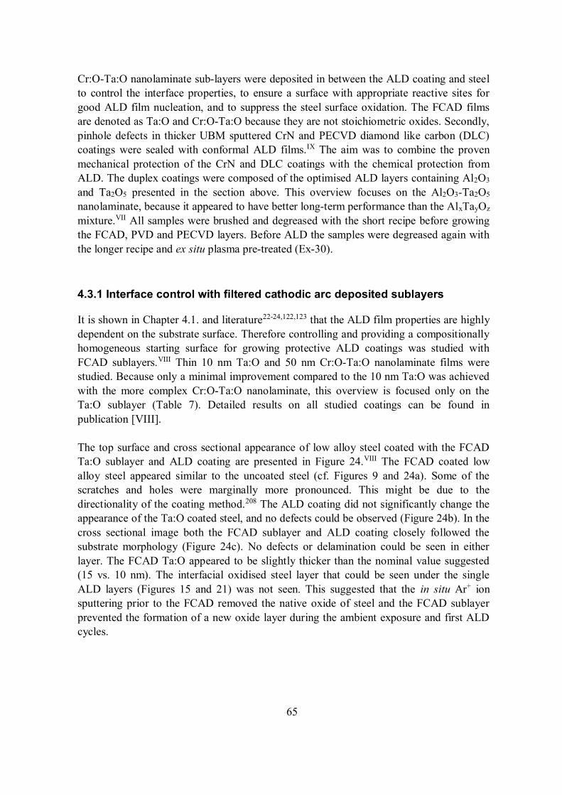
65
Cr:O-Ta:O nanolaminate sub-layers were deposited in between the ALD coating and steelto control the interface properties, to ensure a surface with appropriate reactive sites forgood ALD film nucleation, and to suppress the steel surface oxidation. The FCAD filmsare denoted as Ta:O and Cr:O-Ta:O because they are not stoichiometric oxides. Secondly,pinhole defects in thicker UBM sputtered CrN and PECVD diamond like carbon (DLC)coatings were sealed with conformal ALD films.IX The aim was to combine the provenmechanical protection of the CrN and DLC coatings with the chemical protection fromALD. The duplex coatings were composed of the optimised ALD layers containing Al2O3
and Ta2O5 presented in the section above. This overview focuses on the Al2O3-Ta2O5
nanolaminate, because it appeared to have better long-term performance than the AlxTayOz
mixture.VII All samples were brushed and degreased with the short recipe before growingthe FCAD, PVD and PECVD layers. Before ALD the samples were degreased again withthe longer recipe and ex situ plasma pre-treated (Ex-30).
4.3.1 Interface control with filtered cathodic arc deposited sublayers
It is shown in Chapter 4.1. and literature22-24,122,123 that the ALD film properties are highlydependent on the substrate surface. Therefore controlling and providing a compositionallyhomogeneous starting surface for growing protective ALD coatings was studied withFCAD sublayers.VIII Thin 10 nm Ta:O and 50 nm Cr:O-Ta:O nanolaminate films werestudied. Because only a minimal improvement compared to the 10 nm Ta:O was achievedwith the more complex Cr:O-Ta:O nanolaminate, this overview is focused only on theTa:O sublayer (Table 7). Detailed results on all studied coatings can be found inpublication [VIII].
The top surface and cross sectional appearance of low alloy steel coated with the FCADTa:O sublayer and ALD coating are presented in Figure 24.VIII The FCAD coated lowalloy steel appeared similar to the uncoated steel (cf. Figures 9 and 24a). Some of thescratches and holes were marginally more pronounced. This might be due to thedirectionality of the coating method.208 The ALD coating did not significantly change theappearance of the Ta:O coated steel, and no defects could be observed (Figure 24b). In thecross sectional image both the FCAD sublayer and ALD coating closely followed thesubstrate morphology (Figure 24c). No defects or delamination could be seen in eitherlayer. The FCAD Ta:O appeared to be slightly thicker than the nominal value suggested(15 vs. 10 nm). The interfacial oxidised steel layer that could be seen under the singleALD layers (Figures 15 and 21) was not seen. This suggested that the in situ Ar+ ionsputtering prior to the FCAD removed the native oxide of steel and the FCAD sublayerprevented the formation of a new oxide layer during the ambient exposure and first ALDcycles.
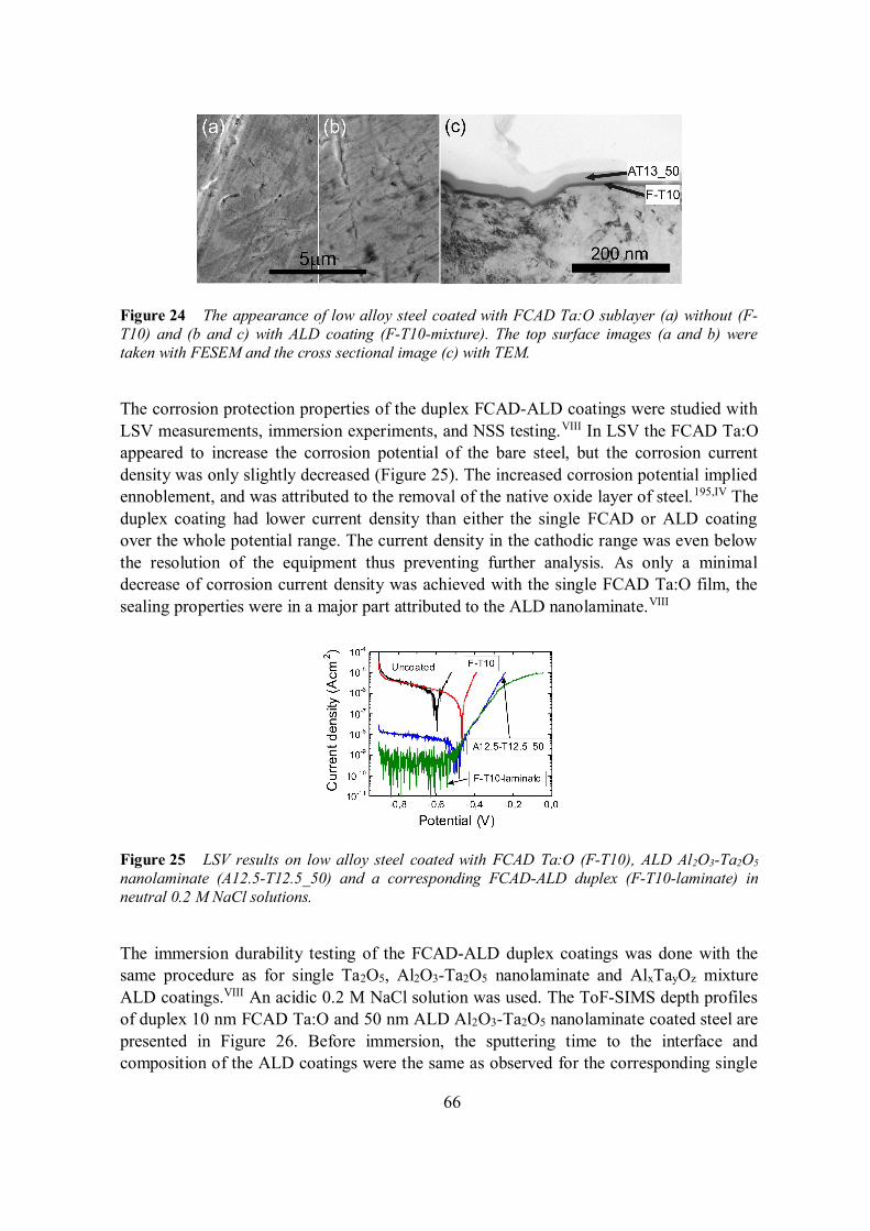
66
Figure 24 The appearance of low alloy steel coated with FCAD Ta:O sublayer (a) without (F-T10) and (b and c) with ALD coating (F-T10-mixture). The top surface images (a and b) weretaken with FESEM and the cross sectional image (c) with TEM.
The corrosion protection properties of the duplex FCAD-ALD coatings were studied withLSV measurements, immersion experiments, and NSS testing.VIII In LSV the FCAD Ta:Oappeared to increase the corrosion potential of the bare steel, but the corrosion currentdensity was only slightly decreased (Figure 25). The increased corrosion potential impliedennoblement, and was attributed to the removal of the native oxide layer of steel.195,IV Theduplex coating had lower current density than either the single FCAD or ALD coatingover the whole potential range. The current density in the cathodic range was even belowthe resolution of the equipment thus preventing further analysis. As only a minimaldecrease of corrosion current density was achieved with the single FCAD Ta:O film, thesealing properties were in a major part attributed to the ALD nanolaminate.VIII
Figure 25 LSV results on low alloy steel coated with FCAD Ta:O (F-T10), ALD Al2O3-Ta2O5
nanolaminate (A12.5-T12.5_50) and a corresponding FCAD-ALD duplex (F-T10-laminate) inneutral 0.2 M NaCl solutions.
The immersion durability testing of the FCAD-ALD duplex coatings was done with thesame procedure as for single Ta2O5, Al2O3-Ta2O5 nanolaminate and AlxTayOz mixtureALD coatings.VIII An acidic 0.2 M NaCl solution was used. The ToF-SIMS depth profilesof duplex 10 nm FCAD Ta:O and 50 nm ALD Al2O3-Ta2O5 nanolaminate coated steel arepresented in Figure 26. Before immersion, the sputtering time to the interface andcomposition of the ALD coatings were the same as observed for the corresponding single
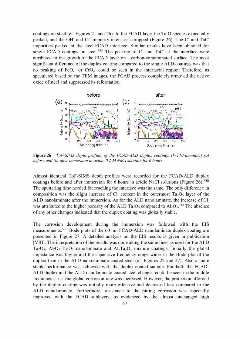
67
coatings on steel (cf. Figures 21 and 26). In the FCAD layer the Ta:O species expectedlypeaked, and the OH- and Cl- impurity intensities dropped (Figure 26). The C- and TaC-
impurities peaked at the steel-FCAD interface. Similar results have been obtained forsingle FCAD coatings on steel.195 The peaking of C- and TaC- at the interface wereattributed to the growth of the FCAD layer on a carbon-contaminated surface. The mostsignificant difference of the duplex coating compared to the single ALD coatings was thatno peaking of FeO2
- or CrO2- could be seen in the interfacial region. Therefore, as
speculated based on the TEM images, the FCAD process completely removed the nativeoxide of steel and suppressed its reformation.
Figure 26 ToF-SIMS depth profiles of the FCAD-ALD duplex coatings (F-T10-laminate) (a)before and (b) after immersion in acidic 0.2 M NaCl solution for 6 hours.
Almost identical ToF-SIMS depth profiles were recorded for the FCAD-ALD duplexcoatings before and after immersion for 6 hours in acidic NaCl solutions (Figure 26).VIII
The sputtering time needed for reaching the interface was the same. The only difference incomposition was the slight increase of Cl- content in the outermost Ta2O5 layer of theALD nanolaminate after the immersion. As for the ALD nanolaminate, the increase of Cl-
was attributed to the higher porosity of the ALD Ta2O5 compared to Al2O3.113 The absenceof any other changes indicated that the duplex coating was globally stable.
The corrosion development during the immersion was followed with the EISmeasurements.VIII Bode plots of the 60 nm FCAD-ALD nanolaminate duplex coating arepresented in Figure 27. A detailed analysis on the EIS results is given in publication[VIII]. The interpretation of the results was done along the same lines as used for the ALDTa2O5, Al2O5-Ta2O5 nanolaminate and AlxTayOz mixture coatings. Initially the globalimpedance was higher and the capacitive frequency range wider in the Bode plot of theduplex than in the ALD nanolaminate coated steel (cf. Figures 22 and 27). Also a morestable performance was achieved with the duplex-coated sample. For both the FCAD-ALD duplex and the ALD nanolaminate coated steel changes could be seen in the middlefrequencies, i.e. the global corrosion rate was increased. However, the protection affordedby the duplex coating was initially more effective and decreased less compared to theALD nanolaminate. Furthermore, resistance to the pitting corrosion was especiallyimproved with the FCAD sublayers, as evidenced by the almost unchanged high
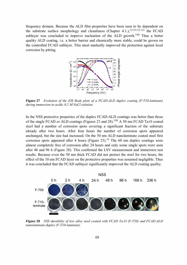
68
frequency domain. Because the ALD film properties have been seen to be dependent onthe substrate surface morphology and cleanliness (Chapter 4.1.),22-24,122,123 the FCADsublayer was concluded to improve nucleation of the ALD growth.VIII Thus a betterquality ALD coating, i.e. a better barrier and chemically more stable, could be grown onthe controlled FCAD sublayer. This most markedly improved the protection against localcorrosion by pitting.
Figure 27 Evolution of the EIS Bode plots of a FCAD-ALD duplex coating (F-T10-laminate)during immersion in acidic 0.2 M NaCl solution.
In the NSS protective properties of the duplex FCAD-ALD coatings was better than thoseof the single FCAD or ALD coatings (Figures 23 and 28).VIII A 50 nm FCAD Ta:O coatedsteel had a number of corrosion spots covering a significant fraction of the substratealready after two hours. After four hours the number of corrosion spots appearedunchanged, but the size had increased. On the 50 nm ALD nanolaminate coated steel firstcorrosion spots appeared after 4 hours (Figure 23).VI The 60 nm duplex coatings werealmost completely free of corrosion after 24 hours and only some single spots were seenafter 48 and 96 h (Figure 28). This confirmed the LSV measurement and immersion testresults. Because even the 50 nm thick FCAD did not protect the steel for two hours, theeffect of the 10 nm FCAD layer on the protective properties was assumed negligible. Thusit was concluded that the FCAD sublayer significantly improved the ALD coating quality.
Figure 28 NSS durability of low alloy steel coated with FCAD Ta:O (F-T50) and FCAD-ALDnanolaminate duplex (F-T10-laminate).
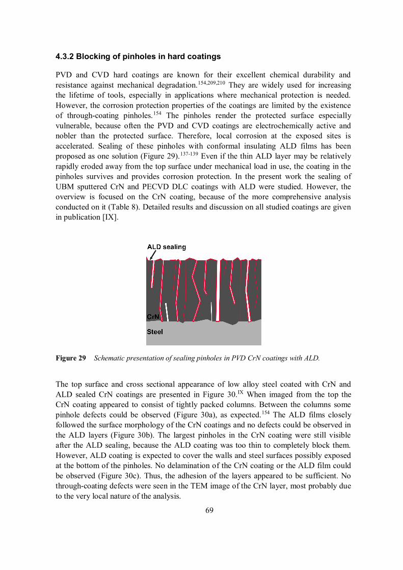
69
4.3.2 Blocking of pinholes in hard coatings
PVD and CVD hard coatings are known for their excellent chemical durability andresistance against mechanical degradation.154,209,210 They are widely used for increasingthe lifetime of tools, especially in applications where mechanical protection is needed.However, the corrosion protection properties of the coatings are limited by the existenceof through-coating pinholes.154 The pinholes render the protected surface especiallyvulnerable, because often the PVD and CVD coatings are electrochemically active andnobler than the protected surface. Therefore, local corrosion at the exposed sites isaccelerated. Sealing of these pinholes with conformal insulating ALD films has beenproposed as one solution (Figure 29).137-139 Even if the thin ALD layer may be relativelyrapidly eroded away from the top surface under mechanical load in use, the coating in thepinholes survives and provides corrosion protection. In the present work the sealing ofUBM sputtered CrN and PECVD DLC coatings with ALD were studied. However, theoverview is focused on the CrN coating, because of the more comprehensive analysisconducted on it (Table 8). Detailed results and discussion on all studied coatings are givenin publication [IX].
Figure 29 Schematic presentation of sealing pinholes in PVD CrN coatings with ALD.
The top surface and cross sectional appearance of low alloy steel coated with CrN andALD sealed CrN coatings are presented in Figure 30.IX When imaged from the top theCrN coating appeared to consist of tightly packed columns. Between the columns somepinhole defects could be observed (Figure 30a), as expected.154 The ALD films closelyfollowed the surface morphology of the CrN coatings and no defects could be observed inthe ALD layers (Figure 30b). The largest pinholes in the CrN coating were still visibleafter the ALD sealing, because the ALD coating was too thin to completely block them.However, ALD coating is expected to cover the walls and steel surfaces possibly exposedat the bottom of the pinholes. No delamination of the CrN coating or the ALD film couldbe observed (Figure 30c). Thus, the adhesion of the layers appeared to be sufficient. Nothrough-coating defects were seen in the TEM image of the CrN layer, most probably dueto the very local nature of the analysis.
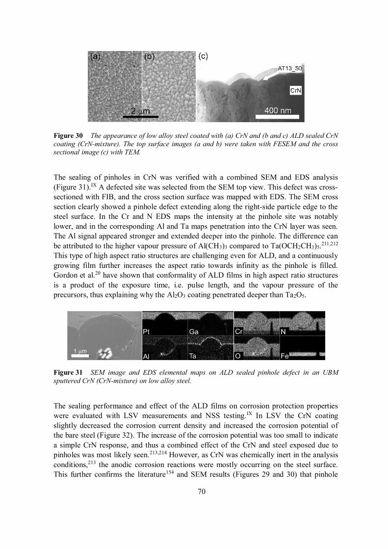
70
Figure 30 The appearance of low alloy steel coated with (a) CrN and (b and c) ALD sealed CrNcoating (CrN-mixture). The top surface images (a and b) were taken with FESEM and the crosssectional image (c) with TEM.
The sealing of pinholes in CrN was verified with a combined SEM and EDS analysis(Figure 31).IX A defected site was selected from the SEM top view. This defect was cross-sectioned with FIB, and the cross section surface was mapped with EDS. The SEM crosssection clearly showed a pinhole defect extending along the right-side particle edge to thesteel surface. In the Cr and N EDS maps the intensity at the pinhole site was notablylower, and in the corresponding Al and Ta maps penetration into the CrN layer was seen.The Al signal appeared stronger and extended deeper into the pinhole. The difference canbe attributed to the higher vapour pressure of Al(CH3)3 compared to Ta(OCH2CH3)5.211,212
This type of high aspect ratio structures are challenging even for ALD, and a continuouslygrowing film further increases the aspect ratio towards infinity as the pinhole is filled.Gordon et al.20 have shown that conformality of ALD films in high aspect ratio structuresis a product of the exposure time, i.e. pulse length, and the vapour pressure of theprecursors, thus explaining why the Al2O3 coating penetrated deeper than Ta2O5.
Figure 31 SEM image and EDS elemental maps on ALD sealed pinhole defect in an UBMsputtered CrN (CrN-mixture) on low alloy steel.
The sealing performance and effect of the ALD films on corrosion protection propertieswere evaluated with LSV measurements and NSS testing.IX In LSV the CrN coatingslightly decreased the corrosion current density and increased the corrosion potential ofthe bare steel (Figure 32). The increase of the corrosion potential was too small to indicatea simple CrN response, and thus a combined effect of the CrN and steel exposed due topinholes was most likely seen.213,214 However, as CrN was chemically inert in the analysisconditions,213 the anodic corrosion reactions were mostly occurring on the steel surface.This further confirms the literature154 and SEM results (Figures 29 and 30) that pinhole
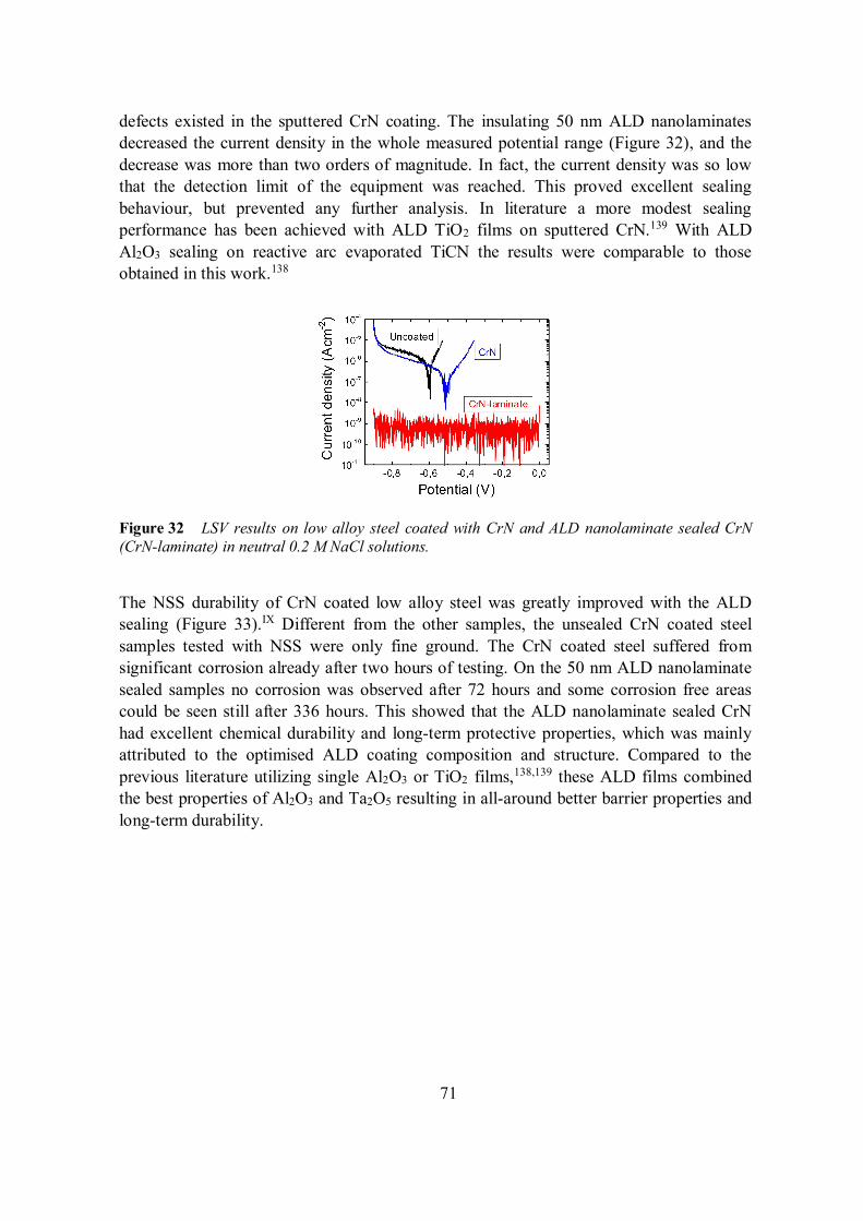
71
defects existed in the sputtered CrN coating. The insulating 50 nm ALD nanolaminatesdecreased the current density in the whole measured potential range (Figure 32), and thedecrease was more than two orders of magnitude. In fact, the current density was so lowthat the detection limit of the equipment was reached. This proved excellent sealingbehaviour, but prevented any further analysis. In literature a more modest sealingperformance has been achieved with ALD TiO2 films on sputtered CrN.139 With ALDAl2O3 sealing on reactive arc evaporated TiCN the results were comparable to thoseobtained in this work.138
Figure 32 LSV results on low alloy steel coated with CrN and ALD nanolaminate sealed CrN(CrN-laminate) in neutral 0.2 M NaCl solutions.
The NSS durability of CrN coated low alloy steel was greatly improved with the ALDsealing (Figure 33).IX Different from the other samples, the unsealed CrN coated steelsamples tested with NSS were only fine ground. The CrN coated steel suffered fromsignificant corrosion already after two hours of testing. On the 50 nm ALD nanolaminatesealed samples no corrosion was observed after 72 hours and some corrosion free areascould be seen still after 336 hours. This showed that the ALD nanolaminate sealed CrNhad excellent chemical durability and long-term protective properties, which was mainlyattributed to the optimised ALD coating composition and structure. Compared to theprevious literature utilizing single Al2O3 or TiO2 films,138,139 these ALD films combinedthe best properties of Al2O3 and Ta2O5 resulting in all-around better barrier properties andlong-term durability.
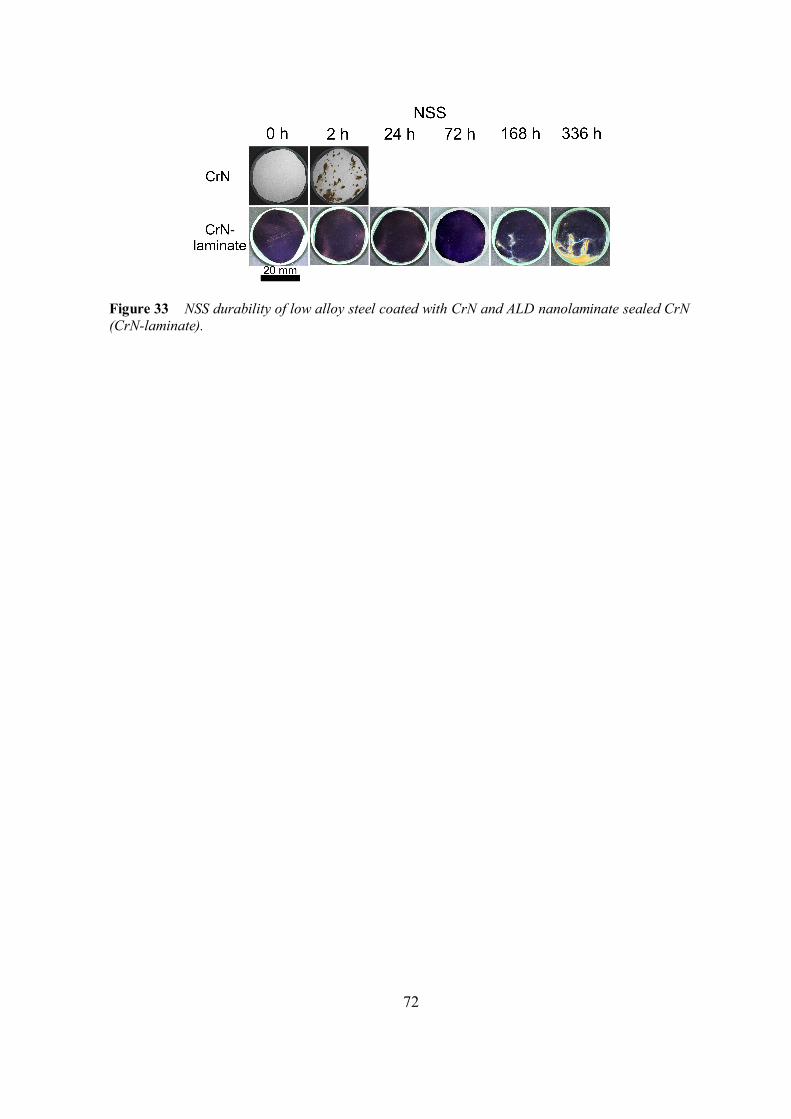
72
Figure 33 NSS durability of low alloy steel coated with CrN and ALD nanolaminate sealed CrN(CrN-laminate).
73
5 Conclusions
In this thesis the protection of metals, metal alloys and metallic constituents inmultimaterial structures with ALD coatings was evaluated. The objective was to study theapplicability of ALD coatings alone and ALD coatings in duplex structures with layersdeposited by other methods for corrosion protection. The effects of the substrate pre-treatment, ALD coating material and deposition parameters to the protective propertiesand the improvement obtained with more complex nanolaminate and mixture coatingscompared to single layers were explored. In the literature review, protection from bothgaseous and liquid corrosives was evaluated. In addition, ALD barriers against metaldiffusion were shortly overviewed. The experimental work was focused on optimizing thesubstrate pre-treatment, the protective properties of ALD coatings based on Al2O3 andTa2O5 and studying the failure mechanisms. The optimised structures were combined withPVD and PECVD grown coatings for synergistically enhanced protection.
A low alloy steel was selected as the material to be protected. The mechanicalconditioning and pre-treatment of the steel surface were found critical for achievingoptimal protection with ALD coatings. Both decreasing the surface roughness andefficient cleaning of the surface with H2-Ar plasma were found beneficial. Theimprovements were attributed to improved ALD nucleation on the smoother and cleanersurface, and lowered defect formation after the deposition due to detachment of foreignparticles or steel flakes.
When optimising the protective properties of the ALD coatings, Al2O3 was found to havesuperior sealing properties, but also to dissolve from the low alloy steel surface even inneutral NaCl solutions. The dissolution was attributed to local increase of pH due to thecathodic reduction of O2 at the bottom of pinholes exposing the steel surface. Ta2O5 wasfound chemically more stable, but inherently less protective due to impurities andmoderate insulating properties. The best corrosion protection was achieved whennanolaminates and mixtures were used, with nanolaminates providing better long-termprotection. The optimum protective properties required a balanced composition of Al2O3
and Ta2O5 in the mixture coatings, and an optimised bilayer structure in thenanolaminates.
A further improvement in the long-term protective properties of ALD coatings could beachieved with duplex PVD-ALD and PECVD-ALD coatings. A thin Ta:O FCAD sublayereffectively separated the ALD process from the steel surface and provided acompositionally controlled starting surface for the ALD growth. This led to improvedsealing properties and better long-term durability. ALD sealing could also be used toblock pinholes in thick PVD and PECVD coatings. Significant improvement in thecorrosion protection properties of hard CrN and DLC coatings was achieved. The ALDsealed hard coatings had a combination of good mechanical durability provided by theCrN or DLC coating and excellent corrosion protection properties provided by the ALDsealing of pinholes, a challenging combination to achieve by either method alone.

74
ALD based protective coatings could be used to achieve effective corrosion protection ofsteel. The coatings themselves had good sealing properties and stability when Al2O3 wascombined with Ta2O5. However, a good substrate-coating interface was challenging toproduce, and both the mechanical conditioning and chemical pre-treatment of the substratewere found critical for producing the proper starting surface for ALD to achieve optimumlong-term protection. Separation of the ALD process from the steel surface was alsobeneficial. Further improvement of the protective properties of ALD coatings onmetallurgical surfaces is likely to require additional consideration on the substrateconditioning and cleaning.
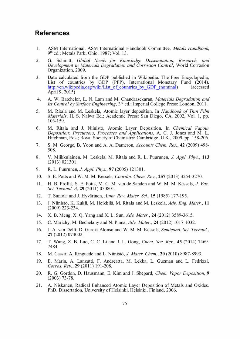
75
References
1. ASM International, ASM International Handbook Committee. Metals Handbook,9th ed.; Metals Park, Ohio, 1987; Vol. 13.
2. G. Schmitt, Global Needs for Knowledge Dissemination, Research, andDevelopment in Materials Degradation and Corrosion Control, World CorrosionOrganization, 2009.
3. Data calculated from the GDP published in Wikipedia: The Free Encyclopedia,List of countries by GDP (PPP), International Monetary Fund (2014).http://en.wikipedia.org/wiki/List_of_countries_by_GDP_(nominal) (accessedApril 9, 2015)
4. A. W. Batchelor, L. N. Lam and M. Chandrasekaran, Materials Degradation andIts Control by Surface Engineering, 3rd ed.; Imperial College Press: London, 2011.
5. M. Ritala and M. Leskelä, Atomic layer deposition. In Handbook of Thin FilmMaterials; H. S. Nalwa Ed.; Academic Press: San Diego, CA, 2002, Vol. 1, pp.103-159.
6. M. Ritala and J. Niinistö, Atomic Layer Deposition. In Chemical VapourDeposition: Precursors, Processes and Applications, A. C. J. Jones and M. L.Hitchman, Eds.; Royal Society of Chemistry: Cambridge, U.K., 2009, pp. 158-206.
7. S. M. George, B. Yoon and A. A. Dameron, Accounts Chem. Res., 42 (2009) 498-508.
8. V. Miikkulainen, M. Leskelä, M. Ritala and R. L. Puurunen, J. Appl. Phys., 113(2013) 021301.
9. R. L. Puurunen, J. Appl. Phys., 97 (2005) 121301.10. S. E. Potts and W. M. M. Kessels, Coordin. Chem. Rev., 257 (2013) 3254-3270.11. H. B. Profijt, S. E. Potts, M. C. M. van de Sanden and W. M. M. Kessels, J. Vac.
Sci. Technol. A, 29 (2011) 050801.12. T. Suntola and J. Hyvärinen, Annu. Rev. Mater. Sci., 15 (1985) 177-195.13. J. Niinistö, K. Kukli, M. Heikkilä, M. Ritala and M. Leskelä, Adv. Eng. Mater., 11
(2009) 223-234.14. X. B. Meng, X. Q. Yang and X. L. Sun, Adv. Mater., 24 (2012) 3589-3615.15. C. Marichy, M. Bechelany and N. Pinna, Adv. Mater., 24 (2012) 1017-1032.16. J. A. van Delft, D. Garcia-Alonso and W. M. M. Kessels, Semicond. Sci. Technol.,
27 (2012) 074002.17. T. Wang, Z. B. Luo, C. C. Li and J. L. Gong, Chem. Soc. Rev., 43 (2014) 7469-
7484.18. M. Cassir, A. Ringuede and L. Niinistö, J. Mater. Chem., 20 (2010) 8987-8993.19. E. Marin, A. Lanzutti, F. Andreatta, M. Lekka, L. Guzman and L. Fedrizzi,
Corros. Rev., 29 (2011) 191-208.20. R. G. Gordon, D. Hausmann, E. Kim and J. Shepard, Chem. Vapor Deposition, 9
(2003) 73-78.21. A. Niskanen, Radical Enhanced Atomic Layer Deposition of Metals and Oxides.
PhD. Dissertation, University of Helsinki, Helsinki, Finland, 2006.
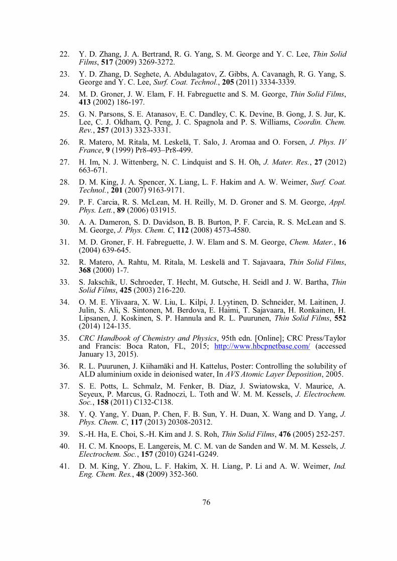
76
22. Y. D. Zhang, J. A. Bertrand, R. G. Yang, S. M. George and Y. C. Lee, Thin SolidFilms, 517 (2009) 3269-3272.
23. Y. D. Zhang, D. Seghete, A. Abdulagatov, Z. Gibbs, A. Cavanagh, R. G. Yang, S.George and Y. C. Lee, Surf. Coat. Technol., 205 (2011) 3334-3339.
24. M. D. Groner, J. W. Elam, F. H. Fabreguette and S. M. George, Thin Solid Films,413 (2002) 186-197.
25. G. N. Parsons, S. E. Atanasov, E. C. Dandley, C. K. Devine, B. Gong, J. S. Jur, K.Lee, C. J. Oldham, Q. Peng, J. C. Spagnola and P. S. Williams, Coordin. Chem.Rev., 257 (2013) 3323-3331.
26. R. Matero, M. Ritala, M. Leskelä, T. Salo, J. Aromaa and O. Forsen, J. Phys. IVFrance, 9 (1999) Pr8-493–Pr8-499.
27. H. Im, N. J. Wittenberg, N. C. Lindquist and S. H. Oh, J. Mater. Res., 27 (2012)663-671.
28. D. M. King, J. A. Spencer, X. Liang, L. F. Hakim and A. W. Weimer, Surf. Coat.Technol., 201 (2007) 9163-9171.
29. P. F. Carcia, R. S. McLean, M. H. Reilly, M. D. Groner and S. M. George, Appl.Phys. Lett., 89 (2006) 031915.
30. A. A. Dameron, S. D. Davidson, B. B. Burton, P. F. Carcia, R. S. McLean and S.M. George, J. Phys. Chem. C, 112 (2008) 4573-4580.
31. M. D. Groner, F. H. Fabreguette, J. W. Elam and S. M. George, Chem. Mater., 16(2004) 639-645.
32. R. Matero, A. Rahtu, M. Ritala, M. Leskelä and T. Sajavaara, Thin Solid Films,368 (2000) 1-7.
33. S. Jakschik, U. Schroeder, T. Hecht, M. Gutsche, H. Seidl and J. W. Bartha, ThinSolid Films, 425 (2003) 216-220.
34. O. M. E. Ylivaara, X. W. Liu, L. Kilpi, J. Lyytinen, D. Schneider, M. Laitinen, J.Julin, S. Ali, S. Sintonen, M. Berdova, E. Haimi, T. Sajavaara, H. Ronkainen, H.Lipsanen, J. Koskinen, S. P. Hannula and R. L. Puurunen, Thin Solid Films, 552(2014) 124-135.
35. CRC Handbook of Chemistry and Physics, 95th edn. [Online]; CRC Press/Taylorand Francis: Boca Raton, FL, 2015; http://www.hbcpnetbase.com/ (accessedJanuary 13, 2015).
36. R. L. Puurunen, J. Kiihamäki and H. Kattelus, Poster: Controlling the solubility ofALD aluminium oxide in deionised water, In AVS Atomic Layer Deposition, 2005.
37. S. E. Potts, L. Schmalz, M. Fenker, B. Diaz, J. Swiatowska, V. Maurice, A.Seyeux, P. Marcus, G. Radnoczi, L. Toth and W. M. M. Kessels, J. Electrochem.Soc., 158 (2011) C132-C138.
38. Y. Q. Yang, Y. Duan, P. Chen, F. B. Sun, Y. H. Duan, X. Wang and D. Yang, J.Phys. Chem. C, 117 (2013) 20308-20312.
39. S.-H. Ha, E. Choi, S.-H. Kim and J. S. Roh, Thin Solid Films, 476 (2005) 252-257.40. H. C. M. Knoops, E. Langereis, M. C. M. van de Sanden and W. M. M. Kessels, J.
Electrochem. Soc., 157 (2010) G241-G249.41. D. M. King, Y. Zhou, L. F. Hakim, X. H. Liang, P. Li and A. W. Weimer, Ind.
Eng. Chem. Res., 48 (2009) 352-360.
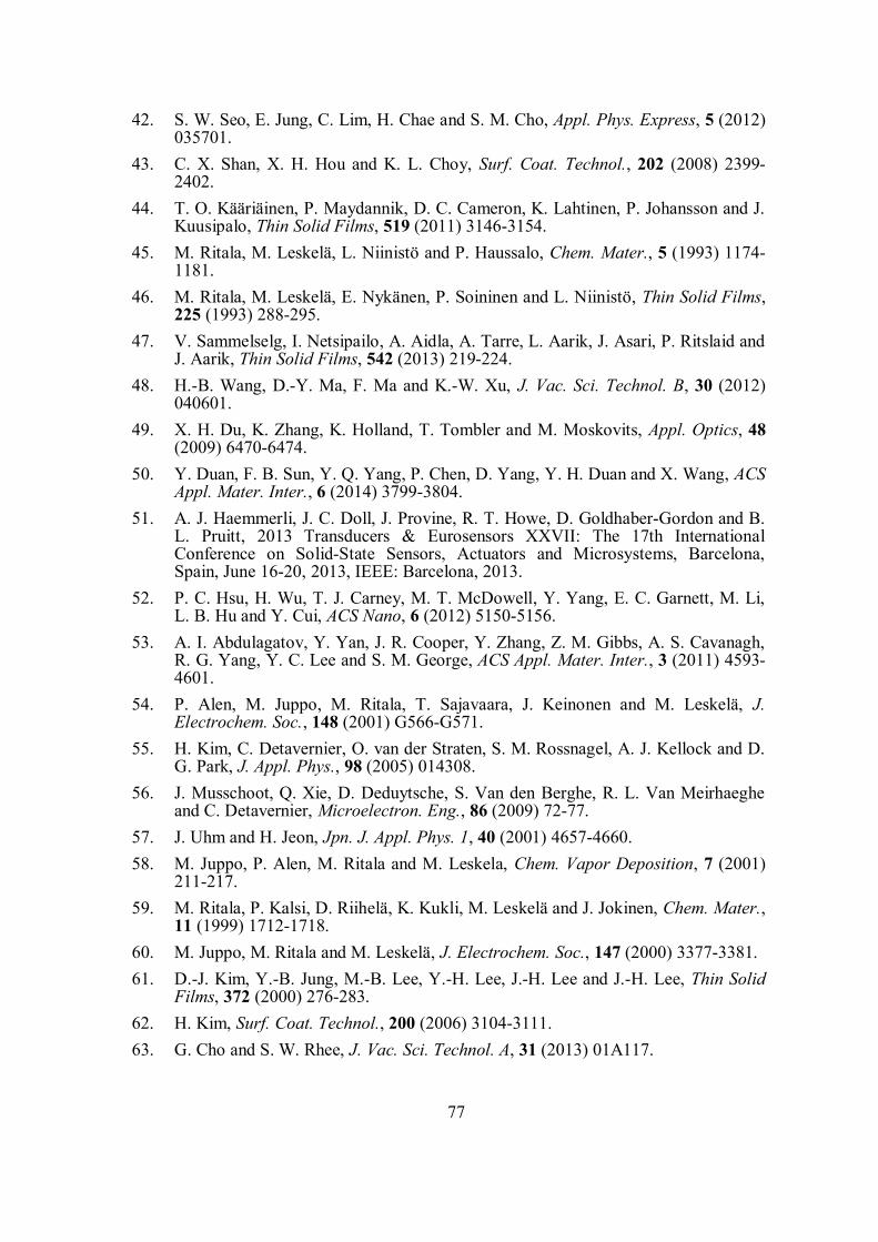
77
42. S. W. Seo, E. Jung, C. Lim, H. Chae and S. M. Cho, Appl. Phys. Express, 5 (2012)035701.
43. C. X. Shan, X. H. Hou and K. L. Choy, Surf. Coat. Technol., 202 (2008) 2399-2402.
44. T. O. Kääriäinen, P. Maydannik, D. C. Cameron, K. Lahtinen, P. Johansson and J.Kuusipalo, Thin Solid Films, 519 (2011) 3146-3154.
45. M. Ritala, M. Leskelä, L. Niinistö and P. Haussalo, Chem. Mater., 5 (1993) 1174-1181.
46. M. Ritala, M. Leskelä, E. Nykänen, P. Soininen and L. Niinistö, Thin Solid Films,225 (1993) 288-295.
47. V. Sammelselg, I. Netsipailo, A. Aidla, A. Tarre, L. Aarik, J. Asari, P. Ritslaid andJ. Aarik, Thin Solid Films, 542 (2013) 219-224.
48. H.-B. Wang, D.-Y. Ma, F. Ma and K.-W. Xu, J. Vac. Sci. Technol. B, 30 (2012)040601.
49. X. H. Du, K. Zhang, K. Holland, T. Tombler and M. Moskovits, Appl. Optics, 48(2009) 6470-6474.
50. Y. Duan, F. B. Sun, Y. Q. Yang, P. Chen, D. Yang, Y. H. Duan and X. Wang, ACSAppl. Mater. Inter., 6 (2014) 3799-3804.
51. A. J. Haemmerli, J. C. Doll, J. Provine, R. T. Howe, D. Goldhaber-Gordon and B.L. Pruitt, 2013 Transducers & Eurosensors XXVII: The 17th InternationalConference on Solid-State Sensors, Actuators and Microsystems, Barcelona,Spain, June 16-20, 2013, IEEE: Barcelona, 2013.
52. P. C. Hsu, H. Wu, T. J. Carney, M. T. McDowell, Y. Yang, E. C. Garnett, M. Li,L. B. Hu and Y. Cui, ACS Nano, 6 (2012) 5150-5156.
53. A. I. Abdulagatov, Y. Yan, J. R. Cooper, Y. Zhang, Z. M. Gibbs, A. S. Cavanagh,R. G. Yang, Y. C. Lee and S. M. George, ACS Appl. Mater. Inter., 3 (2011) 4593-4601.
54. P. Alen, M. Juppo, M. Ritala, T. Sajavaara, J. Keinonen and M. Leskelä, J.Electrochem. Soc., 148 (2001) G566-G571.
55. H. Kim, C. Detavernier, O. van der Straten, S. M. Rossnagel, A. J. Kellock and D.G. Park, J. Appl. Phys., 98 (2005) 014308.
56. J. Musschoot, Q. Xie, D. Deduytsche, S. Van den Berghe, R. L. Van Meirhaegheand C. Detavernier, Microelectron. Eng., 86 (2009) 72-77.
57. J. Uhm and H. Jeon, Jpn. J. Appl. Phys. 1, 40 (2001) 4657-4660.58. M. Juppo, P. Alen, M. Ritala and M. Leskela, Chem. Vapor Deposition, 7 (2001)
211-217.59. M. Ritala, P. Kalsi, D. Riihelä, K. Kukli, M. Leskelä and J. Jokinen, Chem. Mater.,
11 (1999) 1712-1718.60. M. Juppo, M. Ritala and M. Leskelä, J. Electrochem. Soc., 147 (2000) 3377-3381.61. D.-J. Kim, Y.-B. Jung, M.-B. Lee, Y.-H. Lee, J.-H. Lee and J.-H. Lee, Thin Solid
Films, 372 (2000) 276-283.62. H. Kim, Surf. Coat. Technol., 200 (2006) 3104-3111.63. G. Cho and S. W. Rhee, J. Vac. Sci. Technol. A, 31 (2013) 01A117.
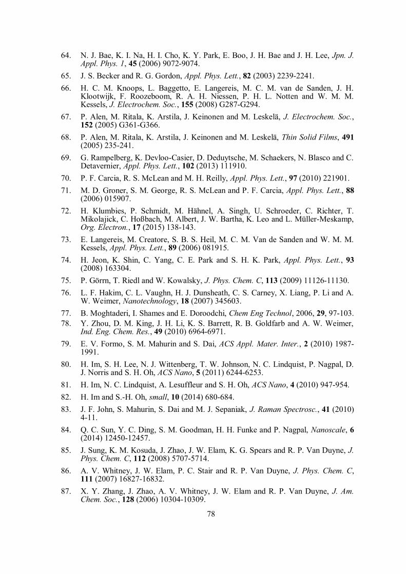
78
64. N. J. Bae, K. I. Na, H. I. Cho, K. Y. Park, E. Boo, J. H. Bae and J. H. Lee, Jpn. J.Appl. Phys. 1, 45 (2006) 9072-9074.
65. J. S. Becker and R. G. Gordon, Appl. Phys. Lett., 82 (2003) 2239-2241.66. H. C. M. Knoops, L. Baggetto, E. Langereis, M. C. M. van de Sanden, J. H.
Klootwijk, F. Roozeboom, R. A. H. Niessen, P. H. L. Notten and W. M. M.Kessels, J. Electrochem. Soc., 155 (2008) G287-G294.
67. P. Alen, M. Ritala, K. Arstila, J. Keinonen and M. Leskelä, J. Electrochem. Soc.,152 (2005) G361-G366.
68. P. Alen, M. Ritala, K. Arstila, J. Keinonen and M. Leskelä, Thin Solid Films, 491(2005) 235-241.
69. G. Rampelberg, K. Devloo-Casier, D. Deduytsche, M. Schaekers, N. Blasco and C.Detavernier, Appl. Phys. Lett., 102 (2013) 111910.
70. P. F. Carcia, R. S. McLean and M. H. Reilly, Appl. Phys. Lett., 97 (2010) 221901.71. M. D. Groner, S. M. George, R. S. McLean and P. F. Carcia, Appl. Phys. Lett., 88
(2006) 015907.72. H. Klumbies, P. Schmidt, M. Hähnel, A. Singh, U. Schroeder, C. Richter, T.
Mikolajick, C. Hoßbach, M. Albert, J. W. Bartha, K. Leo and L. Müller-Meskamp,Org. Electron., 17 (2015) 138-143.
73. E. Langereis, M. Creatore, S. B. S. Heil, M. C. M. Van de Sanden and W. M. M.Kessels, Appl. Phys. Lett., 89 (2006) 081915.
74. H. Jeon, K. Shin, C. Yang, C. E. Park and S. H. K. Park, Appl. Phys. Lett., 93(2008) 163304.
75. P. Görrn, T. Riedl and W. Kowalsky, J. Phys. Chem. C, 113 (2009) 11126-11130.76. L. F. Hakim, C. L. Vaughn, H. J. Dunsheath, C. S. Carney, X. Liang, P. Li and A.
W. Weimer, Nanotechnology, 18 (2007) 345603.77. B. Moghtaderi, I. Shames and E. Doroodchi, Chem Eng Technol, 2006, 29, 97-103.78. Y. Zhou, D. M. King, J. H. Li, K. S. Barrett, R. B. Goldfarb and A. W. Weimer,
Ind. Eng. Chem. Res., 49 (2010) 6964-6971.79. E. V. Formo, S. M. Mahurin and S. Dai, ACS Appl. Mater. Inter., 2 (2010) 1987-
1991.80. H. Im, S. H. Lee, N. J. Wittenberg, T. W. Johnson, N. C. Lindquist, P. Nagpal, D.
J. Norris and S. H. Oh, ACS Nano, 5 (2011) 6244-6253.81. H. Im, N. C. Lindquist, A. Lesuffleur and S. H. Oh, ACS Nano, 4 (2010) 947-954.82. H. Im and S.-H. Oh, small, 10 (2014) 680-684.83. J. F. John, S. Mahurin, S. Dai and M. J. Sepaniak, J. Raman Spectrosc., 41 (2010)
4-11.84. Q. C. Sun, Y. C. Ding, S. M. Goodman, H. H. Funke and P. Nagpal, Nanoscale, 6
(2014) 12450-12457.85. J. Sung, K. M. Kosuda, J. Zhao, J. W. Elam, K. G. Spears and R. P. Van Duyne, J.
Phys. Chem. C, 112 (2008) 5707-5714.86. A. V. Whitney, J. W. Elam, P. C. Stair and R. P. Van Duyne, J. Phys. Chem. C,
111 (2007) 16827-16832.87. X. Y. Zhang, J. Zhao, A. V. Whitney, J. W. Elam and R. P. Van Duyne, J. Am.
Chem. Soc., 128 (2006) 10304-10309.
79
88. M. L. Chang, T. C. Cheng, M. C. Lin, H. C. Lin and M. J. Chen, Appl. Surf. Sci.,258 (2012) 10128-10134.
89. O. M. Hahtela, A. F. Satrapinski, P. H. Sievilä and N. Chekurov, IEEE Trans.Instrum. Meas., 58 (2009) 1183-1187.
90. M. J. M. Mies, E. V. Rebrov, M. H. J. M. de Croon and J. C. Schouten, Chem.Eng. J., 101 (2004) 225-235.
91. M. Muoth, S. W. Lee, K. Chikkadi, M. Mattmann, T. Helbling, A. Intlekofer andC. Hierold, Phys. Status Solidi B, 247 (2010) 2997-3001.
92. M. J. Pellin, J. W. Elam and J. F. Moore, ECS Transactions, 11 (2007) 23-28.93. D. Schmidt, E. Schubert and M. Schubert, Appl. Phys. Lett., 100 (2012) 011912.94. H. G. Yeo and S. Trolier-McKinstry, J. Appl. Phys., 116 (2014) 014105.95. M. J. M. Mies, E. Rebrov, J. C. Jansen, M. H. J. M. Croon and J. C. Schouten, J.
Catal., 247 (2007) 328-338.96. V. Rinnerbauer, Y. X. Yeng, W. R. Chan, J. J. Senkevich, J. D. Joannopoulos, M.
Soljacic and I. Celanovic, Opt. Express, 21 (2013) 11482-11491.97. L. Paussa, L. Guzman, E. Marin, N. Isomaki and L. Fedrizzi, Surf. Coat. Technol.,
206 (2011) 976-980.98. The University of Maryland Home Page, Materials Scientists, Conservators Join
Forces to Preserve Silver Artifacts and Art.http://www.mse.umd.edu/news/news_story.php?id=5270 (accessed March 2,2015).
99. Science Daily Home Page, Nanotechnology Helps Scientists Keep Silver Shiny,http://www.newswise.com/articles/nanotechnology-helps-scientists-keep-silver-shiny (accessed May 3, 2015).
100. M. Mäkelä, P. Soininen and S. Sneck, Protective coating of silver, U.S. Patent8,883,258, November 11, 2014.
101. K. Ali, K.-H. Choi, J. Jo and Y. W. Lee, Mater. Lett., 136 (2014) 90-94.102. C. Y. Chang and F. Y. Tsai, J. Mater. Chem., 21 (2011) 5710-5715.103. C. T. Chou, P. W. Yu, M. H. Tseng, C. C. Hsu, J. J. Shyue, C. C. Wang and F. Y.
Tsai, Adv. Mater., 25 (2013) 1750-1754.104. S. H. Jen, B. H. Lee, S. M. George, R. S. McLean and P. F. Carcia, Appl. Phys.
Lett., 101 (2012) 234103.105. J. Meyer, P. Görrn, F. Bertram, S. Hamwi, T. Winkler, H. H. Johannes, T.
Weimann, P. Hinze, T. Riedl and W. Kowalsky, Adv. Mater., 21 (2009) 1845-1849.
106. D. C. Miller, R. R. Foster, Y. D. Zhang, S. H. Jen, J. A. Bertrand, Z. X. Lu, D.Seghete, J. L. O'Patchen, R. G. Yang, Y. C. Lee, S. M. George and M. L. Dunn, J.Appl. Phys., 105 (2009) 093527.
107. S. W. Seo, E. Jung, C. Lim, H. Chae and S. M. Cho, Thin Solid Films, 520 (2012)6690-6694.
108. A. Singh, F. Nehm, L. Muller-Meskamp, C. Hossbach, M. Albert, U. Schroeder,K. Leo and T. Mikolajick, Org. Electron., 15 (2014) 2587-2592.
109. W. M. Yun, J. Jang, S. Nam, L. H. Kim, S. J. Seo and C. E. Park, ACS Appl.Mater. Inter., 4 (2012) 3247-3253.
80
110. S. H. K. Park, J. Oh, C. S. Hwang, J. I. Lee, Y. S. Yang and H. Y. Chu,Electrochem. Solid-State Lett., 8 (2005) H21-H23.
111. H. Chatham, Surf. Coat. Technol., 78 (1996) 1-9.112. A. Perrotta, E. R. J. van Beekum, G. Aresta, A. Jagia, W. Keuning, R. M. C. M.
van de Sanden, E. W. M. M. Kessels and M. Creatore, Micropor. Mesopor. Mater.,188 (2014) 163-171.
113. B. Diaz, J. Swiatowska, V. Maurice, A. Seyeux, B. Normand, E. Härkönen, M.Ritala and P. Marcus, Electrochim. Acta, 56 (2011) 10516-10523.
114. E. Marin, L. Guzman, A. Lanzutti, W. Ensinger and L. Fedrizzi, Thin Solid Films,522 (2012) 283-288.
115. E. Marin, A. Lanzutti, L. Guzman and L. Fedrizzi, J. Coat. Technol. Res., 8 (2011)655-659.
116. E. Marin, A. Lanzutti, L. Guzman and L. Fedrizzi, Metallogr. Microstr. Anal., 2(2013) 313-320.
117. E. Marin, A. Lanzutti, M. Lekka, L. Guzman, W. Ensinger and L. Fedrizzi, Surf.Coat. Technol., 211 (2012) 84-88.
118. E. Marin, A. Lanzutti, L. Paussa, L. Guzman and L. Fedrizzi, Mater. Corros., 66(2015) 907-914.
119. E. Marin, A. Lanzutti, L. Guzman and L. Fedrizzi, J. Coat. Technol. Res., 9 (2012)347-355.
120. P. C. Wang, Y. T. Shih, M. C. Lin, H. C. Lin, M. J. Chen and K. M. Lin, ThinSolid Films, 518 (2010) 7501-7504.
121. P. C. Wang, Y. T. Shih, M. C. Lin, H. C. Lin, M. J. Chen and K. M. Lin, Surf.Coat. Technol., 204 (2010) 3707-3712.
122. Z. Chai, J. Li, X. Lu and D. He, RCS Adv., 4 (2014) 39365-39371.123. Z. Chai, Y. Liu, J. Li, X. Lu and D. He, RCS Adv., 4 (2014) 50503-50509.124. S. D. Standridge, G. C. Schatz and J. T. Hupp, Langmuir, 25 (2009) 2596-2600.125. S. D. Standridge, G. C. Schatz and J. T. Hupp, J. Am. Chem. Soc., 131 (2009)
8407-8409.126. A. C. Alba-Rubio, B. J. O'Neill, F. Y. Shi, C. Akatay, C. Canlas, T. Li, R. Winans,
J. W. Elam, E. A. Stach, P. M. Voyles and J. A. Dumesic, ACS Catal., 4 (2014)1554-1557.
127. J. C. Lee, D. H. K. Jackson, T. Li, R. E. Winans, J. A. Dumesic, T. F. Kuech andG. W. Huber, Energ. Environ. Sci., 7 (2014) 1657-1660.
128. B. J. O'Neill, D. H. K. Jackson, A. J. Crisci, C. A. Farberow, F. Y. Shi, A. C. Alba-Rubio, J. L. Lu, P. J. Dietrich, X. K. Gu, C. L. Marshall, P. C. Stair, J. W. Elam, J.T. Miller, F. H. Ribeiro, P. M. Voyles, J. Greeley, M. Mavrikakis, S. L. Scott, T. F.Kuech and J. A. Dumesic, Angew. Chem. Int. Edit., 52 (2013) 13808-13812.
129. B. J. O'Neill, C. Sener, D. H. K. Jackson, T. F. Kuech and J. A. Dumesic,ChemSusChem, 7 (2014) 3247-3251.
130. C. C. Kei, Y. S. Yu, J. Racek, D. Vokoun and P. Sittner, J. Mater. Eng. Perform.,23 (2014) 2641-2649.
131. M. Schindler, S. K. Kim, C. S. Hwang, C. Schindler, A. Offenhausser and S.Ingebrandt, Phys. Status Solidi R, 2 (2008) 4-6.
81
132. A. M. Slaney, V. A. Wright, P. J. Meloncelli, K. D. Harris, L. J. West, T. L.Lowary and J. M. Buriak, ACS Appl. Mater. Inter., 3 (2011) 1601-1612.
133. S. Emaminejad, M. Javanmard, R. W. Dutton and R. W. Davis, Anal. Chem., 84(2012) 10793-10801.
134. S. Emaminejad, M. Javanmard, R. W. Dutton and R. W. Davis, ECS Transactions,58 (2013) 67-72.
135. S. Emaminejad, M. Javanmard, C. Gupta, R. W. Dutton, R. W. Davis and R. T.Howe, 2013 Transducers & Eurosensors XXVII: The 17th InternationalConference on Solid-State Sensors, Actuators and Microsystems, Barcelona,Spain, June 16-20, 2013, IEEE: Barcelona, 2013.
136. M. Fedel, C. Zanella, S. Rossi and F. Deflorian, Solar. Energy, 101 (2014) 167-175.
137. Y. P. Hsieh, M. Hofmann, K. W. Chang, J. G. Jhu, Y. Y. Li, K. Y. Chen, C. C.Yang, W. S. Chang and L. C. Chen, ACS Nano, 8 (2014) 443-448.
138. E. Marin, L. Guzman, A. Lanzutti, L. Fedrizzi and M. Saikkonen, Electrochem.Commun., 11 (2009) 2060-2063.
139. C. X. Shan, X. Hou, K. L. Choy and P. Choquet, Surf. Coat. Technol., 202 (2008)2147-2151.
140. P. C. Wang, T. C. Cheng, H. C. Lin, M. J. Chen, K. M. Lin and M. T. Yeh, Appl.Surf. Sci., 270 (2013) 452-456.
141. Z. H. Chen, Y. Qin, K. Amine and Y. K. Sun, J. Mater. Chem., 2010, 20, 7606-7612.
142. A. Mauger and C. Julien, Ionics, 20 (2014) 751-787.143. A. Melendez-Ceballos, V. Albin, S. M. Fernandez-Valverde, A. Ringuede and M.
Cassir, Electrochim. Acta, 140 (2014) 174-181.144. A. Melendez-Ceballos, V. Albin, A. Ringuede, S. M. Fernandez-Valverde and M.
Cassir, Int. J. Hydrogen Energy, 39 (2014) 12233-12241.145. A. Melendez-Ceballos, S. M. Fernandez-Valverde, C. Barrera-Diaz, V. Albin, V.
Lair, A. Ringuede and M. Cassir, Int. J. Hydrogen Energy, 38 (2013) 13443-13452.
146. J. Q. Zhao and Y. Wang, J. Solid State Electr., 17 (2013) 1049-1058.147. Y. W. Chen, J. D. Prange, S. Duhnen, Y. Park, M. Gunji, C. E. D. Chidsey and P.
C. McIntyre, Nat. Mater., 10 (2011) 539-544.148. S. Hu, M. R. Shaner, J. A. Beardslee, M. Lichterman, B. S. Brunschwig and N. S.
Lewis, Science, 344 (2014) 1005-1009.149. A. Paracchino, V. Laporte, K. Sivula, M. Gratzel and E. Thimsen, Nat. Mater., 10
(2011) 456-461.150. C. R. Ottermann, K. Bange, W. Wagner, M. Laube and F. Rauch, Surf. Inter.
Anal., 19 (1992) 435-438.151. K. Kukli, J. Ihanus, M. Ritala and M. Leskelä, J. Electrochem. Soc., 144 (1997)
300-306.152. I. Jogi, K. Kukli, M. Kemell, M. Ritala and M. Leskelä, J. Appl. Phys., 102 (2007)
114114.153. W. Tato and D. Landolt, J. Electrochem. Soc., 145 (1998) 4173-4181.
82
154. M. Fenker, M. Balzer and H. Kappl, Surf. Coat. Technol., 257 (2014) 182-205.155. J. S. Bunch, S. S. Verbridge, J. S. Alden, A. M. van der Zande, J. M. Parpia, H. G.
Craighead and P. L. McEuen, Nano Lett., 8 (2008) 2458-2462.156. S. S. Chen, L. Brown, M. Levendorf, W. W. Cai, S. Y. Ju, J. Edgeworth, X. S. Li,
C. W. Magnuson, A. Velamakanni, R. D. Piner, J. Y. Kang, J. Park and R. S.Ruoff, ACS Nano, 5 (2011) 1321-1327.
157. Y. A. Ono, Electroluminescent Displays, Series on Information Display; WorldScientific: Singapore, Japan, 1995; Vol. 1.
158. P. D. Rack and P. H. Holloway, Mat. Sci. Eng. R, 21 (1998) 171-219.159. A. E. Kaloyeros and E. Eisenbraun, Annu. Rev. Mater. Sci., 30 (2000) 363-385.160. H. Kim, J. Vac. Sci. Technol. B, 21 (2003) 2231-2261.161. J. F. M. Oudenhoven, L. Baggetto and P. H. L. Notten, Adv. Energy Mater., 1
(2011) 10-33.162. D. Bae, S. Kwon, J. Oh, W. K. Kim and H. Park, Renew. Energ., 55 (2013) 62-68.163. H. Park, S. C. Kim, H. C. Bae, T. Cheon, S. H. Kim and W. K. Kim, Mol. Cryst.
Liq. Cryst., 551 (2011) 147-153.164. H. Antson, M. Grasserbauer, M. Hamilo, L. Hiltunen, T. Koskinen, M. Leskelä, L.
Niinistö, G. Stingeder and M. Tammenmaa, Fresenius Z. Anal. Chem., 322 (1985)175-180.
165. P. Cogez, M. Graef, B. Huizing, R. Mahnkopf, H. Ishiuchi, N. Ikumi, S. Choi, J.H. Choi, C. H. Diaz, Y. C. See, P. Gargini, T. Kingscott and I. Steff, The 2013International Technology Roadmap for Semiconductors (ITRS),http://www.itrs.net/home.html (accessed February 11, 2015).
166. K. E. Elers, V. Saanila, P. J. Soininen, W. M. Li, J. T. Kostamo, S. Haukka, J.Juhanoja and W. F. A. Besling, Chem. Vapor Deposition, 8 (2002) 149-153.
167. Q. Xie, J. Musschoot, C. Detavernier, D. Deduytsche, R. L. Van Meirhaeghe, S.Van den Berghe, Y. L. Jiang, G. P. Ru, B. Z. Li and X. P. Qu, Microelectron. Eng.,85 (2008) 2059-2063.
168. T. E. Hong, T. H. Kim, J. H. Jung, S. H. Kim and H. Kim, J. Am. Ceram. Soc., 97(2014) 127-134.
169. S. H. Kim, S. S. Oh, H. M. Kim, D. H. Kang, K. B. Kim, W. M. Li, S. Haukka andM. Tuominen, J. Electrochem. Soc., 151 (2004) C272-C282.
170. Q. Xie, D. Deduytsche, J. Musschoot, R. L. Van Meirhaeghe, C. Detavernier, S. F.Ding and X. P. Qu, Microelectron. Eng., 88 (2011) 646-650.
171. C. Hossbach, S. Teichert, J. Thomas, L. Wilde, H. Wojcik, D. Schmidt, B.Adolphi, M. Bertram, U. Muhle, M. Albert, S. Menzel, B. Hintze and J. W. Bartha,J. Electrochem. Soc., 156 (2009) H852-H859.
172. S. H. Kim, S. S. Oh, K. B. Kim, D. H. Kang, W. M. Li, S. Haukka and M.Tuominen, Appl. Phys. Lett., 82 (2003) 4486-4488.
173. K. E. Elers, V. Saanila, W. M. Li, P. J. Soininen, J. T. Kostamo, S. Haukka, J.Juhanoja and W. F. A. Besling, Thin Solid Films, 434 (2003) 94-99.
174. P. Alen, M. Vehkamaki, M. Ritala and M. Leskelä, J. Electrochem. Soc., 153(2006) G304-G308.
175. P. Majumder, R. Katamreddy and C. Takoudis, J. Cryst. Growth, 309 (2007) 12-17.
83
176. P. Majumder, R. Katamreddy and C. Takoudis, Electrochem. Solid-State Lett., 10(2007) H291-H295.
177. H. Wojcik, U. Merkel, A. Jahn, K. Richter, M. Junige, C. Klein, J. Gluch, M.Albert, F. Munnik, C. Wenzel and J. W. Bartha, Microelectron. Eng., 88 (2011)641-645.
178. D. Greenslit, S. Kumar, T. Chakraborty and E. Eisenbraun, ECS Transactions, 13(2008) 63-70.
179. T. E. Hong, T. Cheon, S. H. Kim, J. K. Kim, Y. B. Park, O. J. Kwon, M. J. Kimand J. J. Kim, J. Alloy Compd., 580 (2013) 72-81.
180. S. H. Kim, H. T. Kim, S. S. Yim, D. J. Lee, K. S. Kim, H. M. Kim, K. B. Kim andH. Sohn, J. Electrochem. Soc., 155 (2008) H589-H594.
181. S. W. Kim, S. H. Kwon, S. J. Jeong and S. W. Kang, J. Electrochem. Soc., 155(2008) H885-H888.
182. S. Kumar, D. Greenslit, T. Chakraborty and E. T. Eisenbraun, J. Vac. Sci. Technol.A, 27 (2009) 572-576.
183. S. H. Kwon, O. K. Kwon, J. S. Min and S. W. Kang, J. Electrochem. Soc., 153(2006) G578-G581.
184. L. Baggetto, H. C. M. Knoops, R. A. H. Niessen, W. M. M. Kessels and P. H. L.Notten, J. Mater. Chem., 20 (2010) 3703-3708.
185. L. Baggetto, J. F. M. Oudenhoven, T. van Dongen, J. H. Klootwijk, M. Mulder, R.A. H. Niessen, M. H. J. M. de Croon and P. H. L. Notten, J. Power Sources, 189(2009) 402-410.
186. H. C. M. Knoops, L. Baggetto, E. Langereis, M. C. M. Van de Sanden, J. H.Klootwijk, F. Roozeboom, R. A. H. Niessen, P. H. L. Notten and W. M. M.Kessels, ECS Transactions, 11 (2007) 45-54.
187. H. C. M. Knoops, M. E. Donders, L. Baggetto, M. C. M. van de Sanden, P. H. L.Notten and W. M. M. Kessels, ECS Transactions, 25 (2009) 333-344.
188. F. Kessler and D. Rudmann, Solar Energy, 77 (2004) 685-695.189. R. Wuerz, A. Eicke, M. Frankenfeld, F. Kessler, M. Powalla, P. Rogin and O.
Yazdani-Assl, Thin Solid Films, 517 (2009) 2415-2418.190. M. Kariniemi, J. Niinisto, M. Vehkamaki, M. Kemell, M. Ritala, M. Leskela and
M. Putkonen, J. Vac. Sci. Technol. A, 30 (2012) 01A115.191. C. E. Ramberg, E. Blanquet, M. Pons, C. Bernard and R. Madar, Microelectron.
Eng., 50 (2000) 357-368.192. CRC Materials Science and Engineering Handbook, 3rd edn.; J. F. Shackelford and
W. Alexander, Eds.; CRC Press: Boca Raton, FL, 2001.193. T. Cheon, S. H. Choi, S. H. Kim and D. H. Kang, Electrochem. Solid-State Lett.,
14 (2011) D57-D61.194. M. Kariniemi, J. Niinistö, T. Hatanpaa, M. Kemell, T. Sajavaara, M. Ritala and M.
Leskelä, Chem. Mater., 23 (2011) 2901-2907.195. B. Diaz, J. Swiatowska, V. Maurice, M. Pisarek, A. Seyeux, S. Zanna, S.
Tervakangas, J. Kolehmainen and P. Marcus, Surf. Coat. Technol., 206 (2012)3903-3910.
196. M. Ylilammi and T. Ranta-aho, Thin Solid Films, 232 (1993) 56-62.
84
197. T. J. Lin, J. A. Antonelli, D. J. Yang, H. K. Yasuda and F. T. Wang, Prog. Org.Coat., 31 (1997) 351-361.
198. M. Mozetic, Vacuum, 61 (2001) 367-371.199. H. Steffen, J. Schwarz, H. Kersten, J. F. Behnke and C. Eggs, Thin Solid Films,
283 (1996) 158-164.200. K. Kukli, M. Ritala and M. Leskelä, J. Electrochem. Soc., 142 (1995) 1670-1675.201. G. S. Frankel, J. Electrochem. Soc., 145 (1998) 2186-2198.202. P. Marcus, V. Maurice and H. H. Strehblow, Corros. Sci., 50 (2008) 2698-2704.203. A. Bonnel, F. Dabosi, C. Deslouis, M. Duprat, M. Keddam and B. Tribollet, J.
Electrochem. Soc., 130 (1983) 753-761.204. I. Epelboin, M. Keddam and J. C. Lestrade, Farad. Discuss., 56 (1973) 264-275.205. P. Li, T. C. Tan and J. Y. Lee, Corros. Sci., 38 (1996) 1935-1955.206. F. Wenger, S. Cheriet, B. Talhi and J. Galland, Corros. Sci., 39 (1997) 1239-1252.207. A. M. Belu, D. J. Graham and D. G. Castner, Biomaterials, 24 (2003) 3635-3653.208. I. G. Brown, Annu. Rev. Mater. Sci., 28 (1998) 243-269.209. P. J. Kelly and R. D. Arnell, Vacuum, 56 (2000) 159-172.210. W. D. Sproul, Surf. Coat. Technol., 81 (1996) 1-7.211. M. Fulem, K. Ruzicka, V. Ruzicka, E. Hulicius, T. Simecek, K. Melichar, J.
Pangrac, S. A. Rushworth and L. M. Smith, J. Cryst. Growth, 248 (2003) 99-107.212. T. Li, W.-W. Zhuang, S. T. Hsu, MOCVD precursors in mixed solvents. U.S.
Patent 6,503,314, June 7, 2003.213. J. Creus, H. Mazille and H. Idrissi, Surf. Coat. Technol., 130 (2000) 224-232.214. C. Mendibide, P. Steyer and J. P. Millet, Surf. Coat. Technol., 200 (2005) 109-112.