Embed Size (px)
Citation preview
I JFRAKED-MICROWAVE FREQUENCY S' NTHESIS DESIGN:
SOME RELEVANT CONCEPTUAL NOISE ASPECTS*j
Donald Halford
Atomic Frequency and Time Standards Section National Bureau of Standards Boulder, Colorado 80302 USA
Abstract
Extremely accurate and precise frequency synthesis into the infrared
and visible radiation regions will allow new vistas of metrology, Frequency
and time measurements a r e the basic operations which will be affected, and
impact is expected in such diverse a r e a s as length standards and metrology,
spectroscopy, timekeeping, communications, and relativistic tests.. In
addition the set of independent base units of measurement may change, and
the speed of light may become a conventional (defined) quantity.
attainment of the desired high accuracy and precision will be easiest and
cheapest i f there is careful optimization of the synthesis design aspects
involving noise.
the linewidth of the signal becomes an important parameter.
-. The
When frequencies in the terahertz region are considered,
Due to the
low-frequency-divergence of the instability of good signal sources , the
concept of the fast linewidth becomes of particular importance.
properties and importance af the fast linewidth in system design a r e dis-
Some of the -
cussed in this paper.
Key Words: Allan variance; Base units; Fast linewidth; Frequency multiplication; Frequency noise; Frequency synthesis ; Infrared frcqiiency metrology; Josephson effect; Linewidth; Mcthane f rcqucncy standard; Phase noise; Unified standa x-(1
*Contribution of the Natioml Bureau of Standards, not subject to copyriglit.
1-A talk based on the matcrial in this document was prcsentcd on 1 Septcniimr 1971 at the Seminar on I'rcyiiency Standards and Metrology, Quebec.
4 3 1
INFRARED-MICROWAVE FREQUENCY SYNTHESIS DESIGN:
SOME RELEVANT CONCEPTUAL NOISE ASPECTS
Out1 in c o I C on t cnt s
Abstract
Key Words
I. INTRODUCTION
11. SOME GOALS AND RECENT ACCOMPLISHMENTS
A. Some Intermediate Goals
B. Metrology and Frequency Synthesis
C. A Major Goal: Methane
III. THE FAST LINEWIDTH AND RELATED NOISE CONCEPTS
A. Sources of Noise
B. Power Law Noise Spectral Densities
C. The Importance of the Fast Linewidth
D. Linewidth Calculations
1. One radian rms in the time domain.
2. One radian r m s in the frequency domain.
3. Modified Lorentzians of various orders : The width and shape of the complete fast
. RF power spcctral line.
4. Some propertics of the fast linewidth.
5’. A graphical fast linewidth construction.
6. Utility of W + and Wt as approximations t o the fast lincwidth W f .
IV. DISCUSSION V. REFERENCES
VI. APPENDIX: GLOSSARY O F SYMBOLS
432
. .-
I. INTRODUCTION
I
‘ I
I
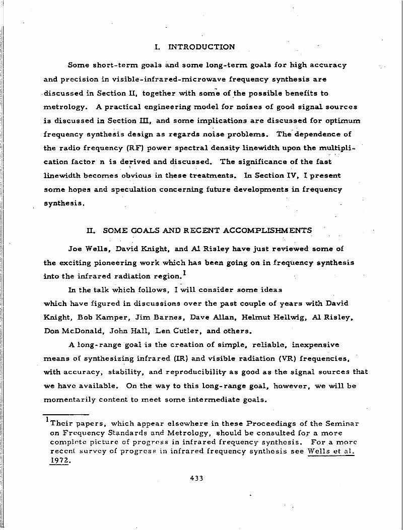
Some short-term goals and some long-term goals for high accuracy
and prccision in visible-infrared-microwave frequency synthesis are
discussed in Section 11, together with som[e of t h e possible benefits to
metrology.
is discussed in Section ILI, and some implications are discussed for optimum
frequency synthesis design a s regards noise problems.
the radio frequency (RF) power spectral density linewidth upon the multipli-
A practical engineering model for noises of good signal sources
The dependence of
linewidth becomes obvious in these treatments. In Section IV, I present
some hopes and speculation concerning future developments in frequency
synthesis.
II. SOME G O A L S AND RECENT ACCOMPLISHMENTS
Joe W e l l s , David Knight, and Al Risley have just reviewed some of
the exciting pioneering work which has been going on in frequency synthesis
into the infrared radiation region. I
In the talk which follows, I will consider some ideas
which have figured in discussions over the past couple of years with David
Knight, Bob Kamper, Jim Barnes, Dave Allan, Helmut Hellwig, Al Risley,
Don McDonald, John Hall, Len Cutler, and others.
A long-range goal is the creation of simple, reliable, inexpensive
means of synthesizing infrared (IR) and visible radiation (VR) frequencies,
with accuracy, stability, and reproducibility as good as the signal sources that
w e havc available.
momentarily content to meet some intermediate goals.
On the way to this long-range goal, however, we will be
1 Thcir papers, which appear elsewhere in these Proceedings of the Seminar on Frequency Standards and Metrology, should be consulted for a more complctc picture of progress i n infrared frequency Synthesis. For a morc reccnl survcy of progress in infrared frequency synthesis see Wells et al . 1972.
4 3 3
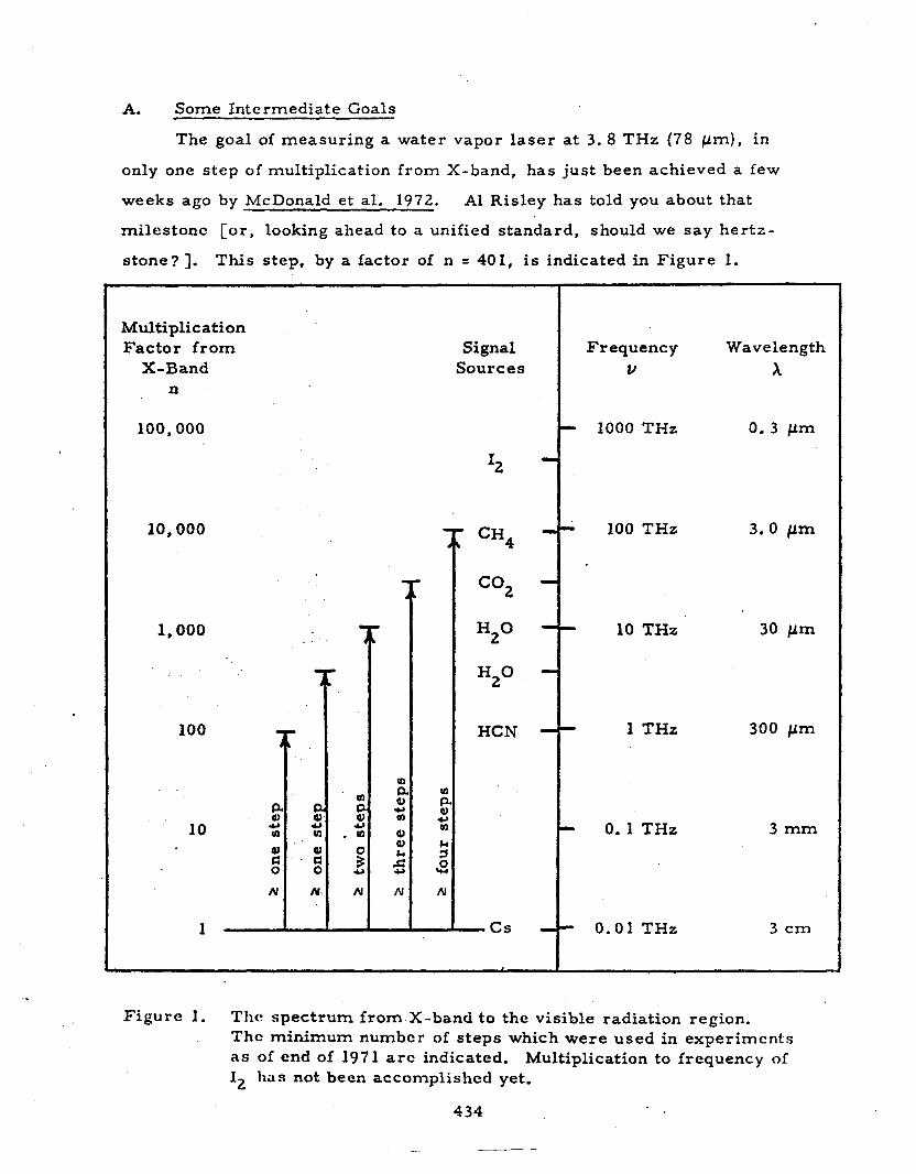
A. Some Intermediate Goals
The goal of measuring a water vapor laser at 3.8 THz (78 pm) , in
only one step of multiplication from X-band, has just been achieved a few
weeks ago by McDonald et al. 1972. A1 Risley has told you about that
milestonc [or , looking ahead to a unified standard, should w e say her tz-
stone?]. This step, by a factor of n = 401, is indicated in Figure 1.
Multiplication Factor f rom X-Band
n
100,000
10,000
1,000
100
10
1
Signal Sources
I2
T cH4
Frequency v
1000 THz
100 THz
10 THz
1 THz
0.1 THz
0.01 THz
Wavelength x
0.3 p m
3.0 p m
30 p m
300 p m
3 mm
3 c m
Figure 1. Tlic spectrum from X-band to the visible radiation region. Thc minimum numbcr of steps which were used in experiments as of end of 1971 arc indicated. Multiplication to frequency of I has not been acconiplishccl yet. 2
434
The measurement of the HCN laser at 0 .89 THz (337 p m ) in only onc
stcp of multiplication (n = 100) from X-band was achieved a year ago by
McDonald et al. 1971. A more difficult, and more significant, goal is to
use only one s t ep of multiplication f rom X-band to measu re the frequency of
the water vapor laser at 10.7 THz (28 pm). Perhaps it cannot be done, but
Don McDonald and Al Risley are sufficiently optimistic about doing it i n one
s tep that they are going to spend some of their time trying it.
will succeed.
I predict they
B. Metrology and Frequency Synthesis
Let u s keep in mind that the ability to measure infrared frequencies
allows us, in general, through appropriate servos, to control and u s e these
signals for many exacting purposes in metrology. The ability to do the
frequency multiplication in the smallest possible number of steps is an
exciting goal, for that ability wi l l allow u s to reduce cost and inconvenience
and to maximize precision, accuracy, and versatility of IR and VR
frequency synthesis.
able to t ransfer the stability and accuracy of various excellent microwave
signal sources [Glaze 1970; Hellwig and Halford 19711 to signals in the IR
and VR; conversely, i f it develops in the future that the best signal sources
are in the IR, then w e will be able to t ransfer their stability and accuracy
t o the other portions of the frequency spectrum.
5-MHz c a r r i e r s as a "working-frequency" for frequency metrology, to use
1-second ticks for time-scale metrology, and to use visible light for length
With good IR/VR/pX frequency synthesis, we will be
It is common to use
. metrology. I note that these prefci-ences can be maintained, and yet, i f
desired, stability and accuracy could be improved by frequency synthesis
f r o m that r eg ion of the spectrum where the best quality signal source exists.
There is no compelling need to choose our pr imary standard so that its
frequency is a t the preferred workin-g frequency of routine metrology.
435
C. A Major Goal: Methane
If one-step multiplication from X-band to 10.7 THz proves to be
feasible by some means, then we could t r y one-step multiplication by a
factor of about three thousand from X-band to the various frequencies of
COz l a s e r s near 29 THz. After that, it would be another factor of about
three up to the frequency of the saturated-absorption methane cell
frequency standard developed by Barger and Hall 1969a.
..
At the moment, and for a t least thedpast two years , the methane
device has been by far the most stable and accurate signal source in the
IR and VR [Barger and Hall 1969a; Barger and Hall 1969b; Hellwirr et al.
- 19723. Although its present accuracy of about one part in IO1' is
considerably less than the accuracy for the microwave cesium beam, its
stability-in the millisecond to one-second range [Hellwig et ai. 1972 J is
unexcelled by any other device.
further improvements both in accuracy and in stability of the methane
device.
There is considerable promise for
2
Hence, a very significant goal, still unattained by means of
frequency metrology as of today (I September 1971), , is the measurement of
the frequency of the saturated-absorption methane cell frequency standard
at.88 THz (3.39 ~ m ) . ~ Full success in the accurate measurement of the
frequency of this ultra-stable frequency source will yield an extremely 4
21 note that lasers, per se, generally a r e no better in stability than a r e microwave klystrons, per se. beam device, the outstanding stability and accuracy arise not from the slave oscillator but from the passive methane and cesium resonances, respcctively. klystron, quartz crystal, Gum) is servoed (slaved) to the frequency of a passive resonance by mcans of frequency metrology. For a discussion of some relevant considerations, see Hellwig 1970.
3The first measurement of the 88-THz methane frequency (in terms of the cesium beam frequency standard) by frequency metrology did occur ten
In the methane device, as in the cesium
In these devices; the frequency of an oscillator (laser,
. wecks la ter , on I1 November 1971 [Evenson et al. 19721. 4Since the methane devicc is not de jure the standard of length, this
determination of the speed of light also requires measurement of thc wavelength of the methane device relative to the krypton- 86 Length stan& rd , as is being done by Bargcr 1971 and by Giacomo 1971.
436 ....
accurate determination of the speed of light, or--using a different language
of metrology- -it will allow accurate length measurements to be referenced
to the cesium beam frequency standard as a primary standard for length,
with the use of a defined nominal value for the speed of light--this is the
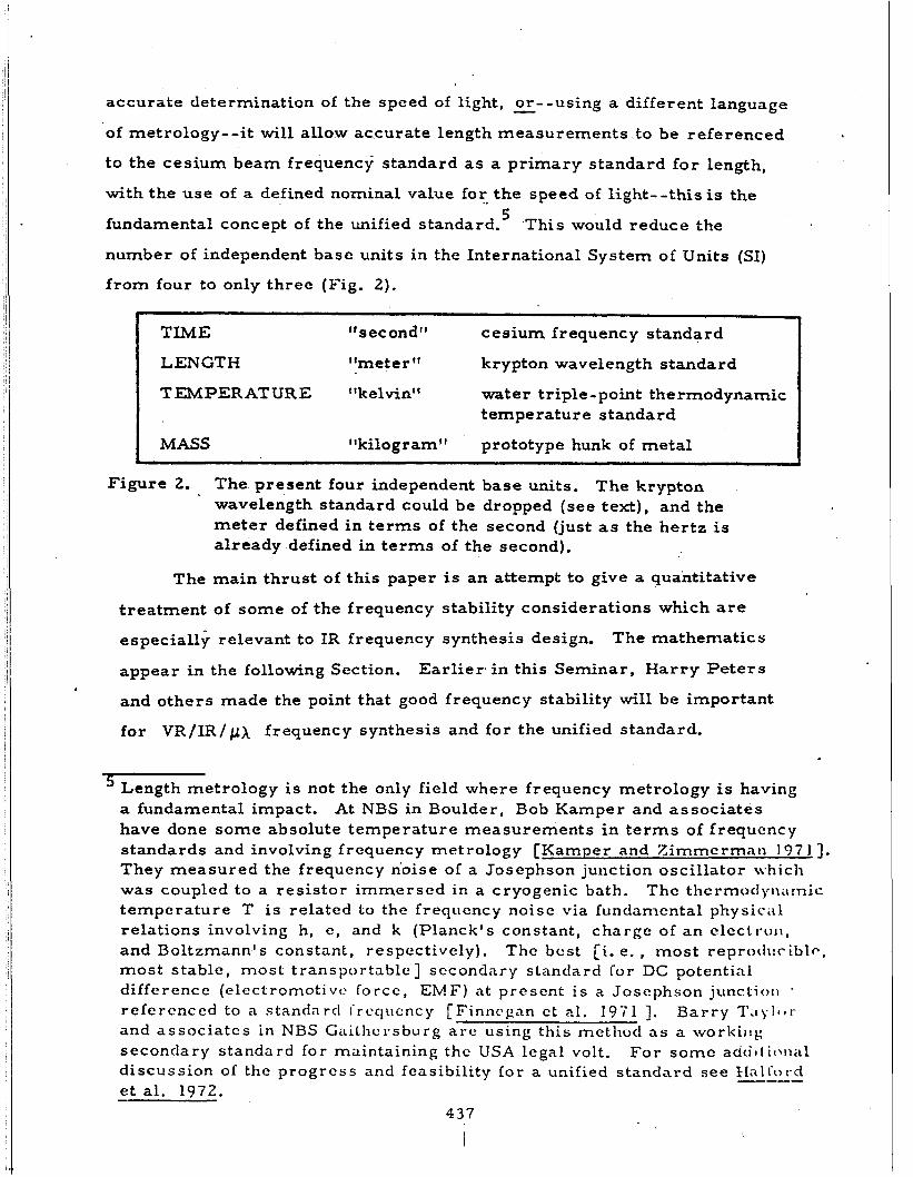
fundamental concept of the unified standard.’ ‘This would reduce the
number of independent base units in the International System of Units (SI)
f rom four to only three (Fig. 2).
-
TIME “second’# cesium frequency standard
LENGTH “meter krypton wavelength standard
TEMPERATURE “kelvintf water triple-point thermodynamic t empe r a tu r e standard
MASS llkilogram’t prototype hunk of metal
Figure 2. The present four independent base units. The krypton wavelength standard could be dropped (see text), and the meter defined in te rms of the second (just as the her tz is already defined in terms of the second).
The main thrust of this paper is an attempt to give a quantitative
treatment of some of the frequency stability considerations which are
especially relevant to IR frequency synthesis design.
appear in the following Section.
and others made the point that good frequency stability will be important
for VR/IR/pX frequency synthesis and for the unified standard.
The mathematics
Earl ier in this Seminar, Harry Peters
’ Length metrology is not the only field where frequency metrology is having a fundamental impact. have done s o m e absolute temperature measurements in t e r m s of frequency standards and involving frequency metrology [Kamper and Zimmcrmnn 197 I ] . They measured the frequency n’oise of a Josephson junction oscillator \vhich was coupled to a resistor immerscd in a cryogenic bath. temperature T i s related Lo the frequcncy noise via fundanicntal physic.11 relations involving h, e, and k (Planck’s constant, charge of an clecti-oil, and Boltzmann’s constant, respectively). The best [i. e. , most reprotluciblc, most stable, most transportable] sccondrrry standard for DC potential difference (elcctromotivc forcc, E M F ) at present i s a Josephson junctioii
At NBS in Boulder, Bob Kamper and associates
Thc thcrmoclyiiarnic
~
refercnccd to a standard f rcc lucncy [ F i n n c g a n ct al. I971 3. Barry T ~ i y I ~ * t - and associatcs in NBS CaiLhcrsburg a r c using this method as a workiiig secondary standard for maintaining thc USA legal volt. discussion of the progress and feasibility lor a unified standard see € i a l f ~ ~ i . c l
For some acio‘tt ic)tial ---
et al. 1972. -
437
Obviously I agree, and it is a crucial argument in m y talk. In addition,
I make the point that, for a given frequency stability performance of the
signal m u r c c s , the optimum utilization of that stability performance will
be co r rc s pondjngly important.
438
III. THE FAST LINEWIDTH AND RELATED NOISE CONCEPTS
I will discuss a few simple concepts that possibly will allow easy
and effective design of low-noise frequency synthesis systems.
down the quantity of perturbing noises, even very weak signals f rom
inefficient non-linear elements (frequency multipliers) can be used for
successful frequency synthesis.
desirable, and should be pursued, but low noise levels are also effective.
A. Sources of Noise
By keeping
Efficiency of harmonic generation is
- .
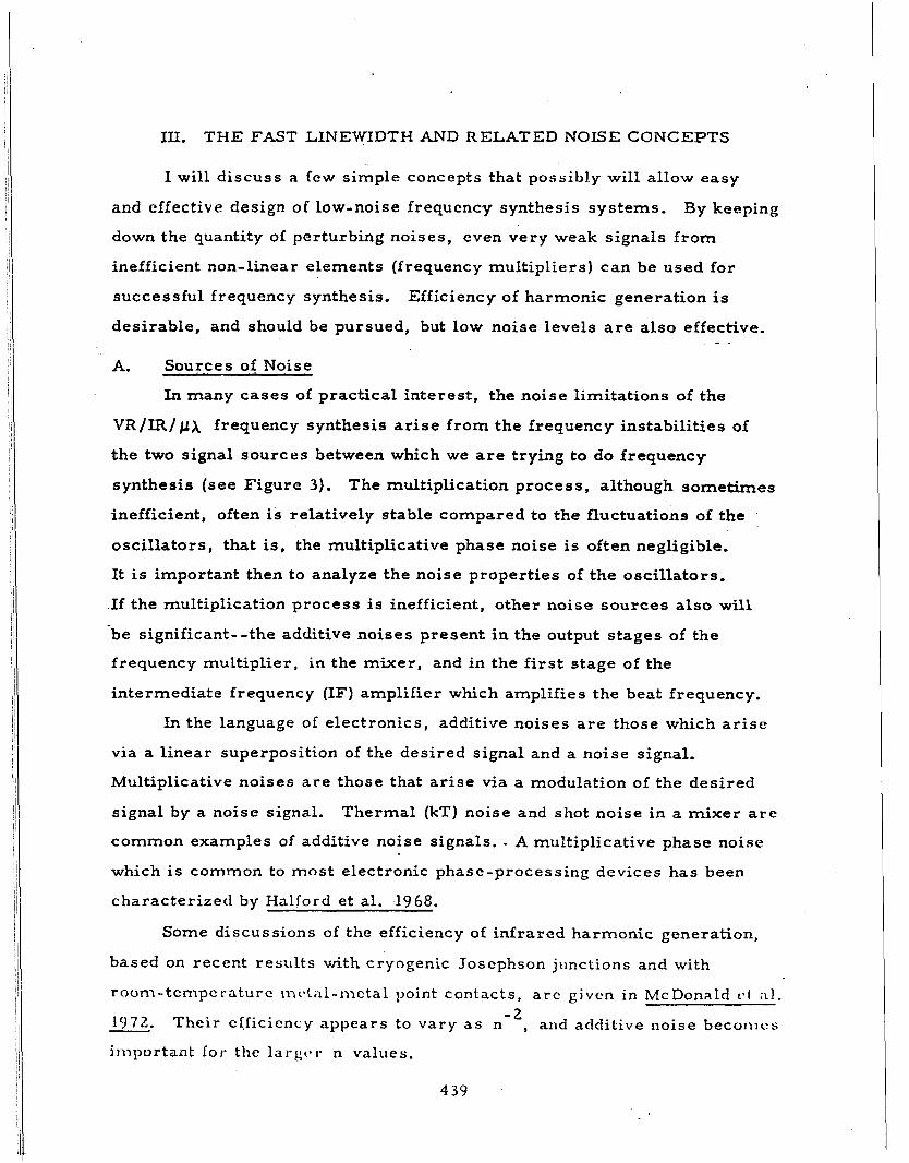
In many cases of practical interest , the noise limitations of the
V R / I R / frequency synthesis arise f rom the frequency instabilities of
the two signal sources between which we are trying to do frequency
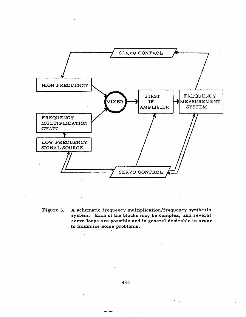
synthesis (see Figurc 3).
inefficient, often is relatively stable compared to the fluctuations of the
oscillators, that is , the multiplicative phase noise is often negligible.
It is important then to analyze the noise properties of the oscillators.
If the multiplication process is inefficient, other noise sources also will
be significant--the additive noises present in the output stages of the
frequency multiplier, in the mixer , and in the first stage of the
intermediate frequency (IF) amplifier which amplifies the bent frequency.
The multiplication process, although sometimes
In the language of electronics, additive noises a r e those which arise
via a l inear superposition of the desired signal and a noise signal.
Multiplicative noises a r e those that arise via a modulation of the desired
signal by a noise signal.
common examples of additive noise signals. - A multiplicative phase noise
which is common to most electronic phase-processing devices has been
characterized by Halfoi-d et al. 1968.
Thermal (kT) noise and shot noise in a mixer are
Some discussions of the efficiency of infrared harmonic generation,
based on recent results with cryogenic Josephson junctions and with
room-tcmpcraturc nit.tirl-nIctal point contacts, a r c given in McDonald c.1 A I . - 2 1972. Their efficiency appears to vary a s n , and additive noise becorncs
iniportant for the lai-gc*r n values.
4 39
SERVO CONTROL
FREQUENCY MULTIPLICATION CHAIN .
Figure 3. A schematic frequency multiplication/frequency synthesis system. Each of the blocks may be complex, and several servo loops are possible and in general desirable in order to minimize noise problems.
440
.-
..
B. Power Law Noise Spectral Densities
Let ma take as a constraint that I am always going to consider signal
sources (oscillators) that a r e fairly well behaved.
signal sources that I can buy, borrow, design, or build. I will not be
talking about lousy ones, I will be talking about good ones? What we find is
that good signal sources will tend to be describable as having some so r t of
a power law frequency instability over wide ranges of Fourier noise
frequency.
indeed, over the Fourier noise frequency ranges that are going t o be'-
important in microwave, infrared, and visible radiation frequency
synthesis--they usually do have these pleasing noise behaviors.
They are the best
That means they will have a power law phase instability. And _ -
For some
_._-- - - additional discussions of the use of power law spectral densities to
characterize high-quality signal sources, see Barnes -et-al. 397 1 and- __ . . ._-
_, ._
_. - Allan- 19 6 6.
The models I am going to discuss will usually assume that l inear
dr i f t and bright line instabilities either are not present, o r e l se are _. - . h+.adLed--.---.------ _ _ ___ ._ - - - - by some additional circuitry o r by some-additional-mathematical treatment
not explicitly considered in this paper. -. - ~ _ _ _ _ - - - - These non-random instabilities can
be very important and bothersome.
their characterization and cure a r e generally well-understood and are
considerably different in nature, a s compared to the random noise aspects
which a r e the focris of this paper.
C.
They are not emphasized here because
. The Importance of the Fast Linewidth
When we design and build a frequency multiplication systcm and
expect that the output signal will be very weak, we realize that additive
noises will be significant.
additivc noises, under the constraint of having a weak signal, we t r y to
reducc the pretlc-tt-ction effective noise bandwidth of thc measuring systctn
as niuc-11 as possi1)lc.
To minimize the deleterious effects of the
The noise bandwidth is generally se t in thc IF aniptificr.
'For s o m e stntc of-the-art examples, see Brandenhcrger et al. 1971 l o r a quartz crystal oscillator, Glaze 1970 for a multiplier chain with output at X-band, Ashicy and Searles 1968 for a two-cavity X-band klystron, and Hcllwig ct nl. i 972 for an 88-THz methane device.
44 1
t
H o w narrow can we make the noisc bandwidth bclorc wc begin slicing off
significant amounts of the desired signal? If we do not make proper use of
various methods of servo control, of various tracking fi l ters, and of
programmed f i l ters , then we may have to use a relatively large noise
bandwidth to ensure that the desired beat signal i s not itself filtered out by
the IF amplifier. The large bandwidth will pass a large amount of additive
noise, and, if the bandwidth is too large, the desired signal may be
swamped by the additive noise.
But suppose we do make appropriate use of servos and dynamic
Is there then a limit as to how narrow we can make the noise filters.
bandwidth?
zero.
beat signal, which is a function of the fast linewidths of the two signal
sources which are being compared.
The answer is yes, there is a limit, and it is greater than
The limit is set by what I choose to call the fast linewidth of the
The various properties of the fast linewidth will become apparent
later i r ~ this paper.
treatment which I can offer at the moment, a formal mathematical one,
is given in Section III. D. 3,
Several definitions a r e possible. The most rigorous
I). Linewidth Calculations
Some of the noise-linewidth results which I wish to derive and
discuss a r e shown in Fig. 4.
Zn general, I have chosen the symbols, noise measures, andlanguage to be
s imilar to the choice used by Barnes et al. 1971.
A glossary of symbols is given in the Appendix.
In this manuscript I do not explicitly t rea t the cases of power law
spectral densities corresponding to white phase noise (a! = t2) and flicker
phase noise (CY = tl).
behavior of the cascs for CY c t 1.
are either zero for zero noise level or a r e infinite for a non-zero noise
level.
can exist. I will t reat this importint problem elsewhere. .
They have anomalous behavior a s compared to the
Strictly speaking, their fast linewidths
If a high frequcncy cut-off i s introduced, then a finite fast linewidth
442
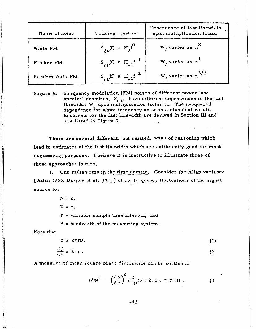
Name of noise
White FM
Flicker F M
Random Walk FM
Dc finin g cqua t i on
-1 S (f) F H 6 V -
2 S (f) I H f - 6 V -2
Dcpendence of fas t linewidth upon multiplication factor
~- 2
W varies as n f
1 W varies as n f
2 /3 W varies as n f
Figure 4. Frequency modulation (FM) noises of different power law spectral densities, S6 v , have different dependences of the fast linewidth Wf upon multiplication factor n, The n-squared dependence for white frequcncy noise is a classical result. Equations for the fast linewidth are derived in Section ILI and are listed in Figure 5 .
There a r e several .different, but related, ways of reasoning which
lead t o estimates of the fast linewidth which are sufficiently good for most
engineering purposes. I believe it is instructive to i l lustrate th ree of
these approaches in turn.
1. One radian rms i n the time domain. Consider the Allan variance
[Allan 1966; B a r n e s et al. 1971) of the frequency fluctuations of the signal
source for
N = 2,
T 2 7,
r = variable sample time interval, and
B = bandwidth of thc ineasuring system.
Note that
@ = 2 T W ,
A measure of m e a n square phase divcrgcnce can be written a s
I" .
443
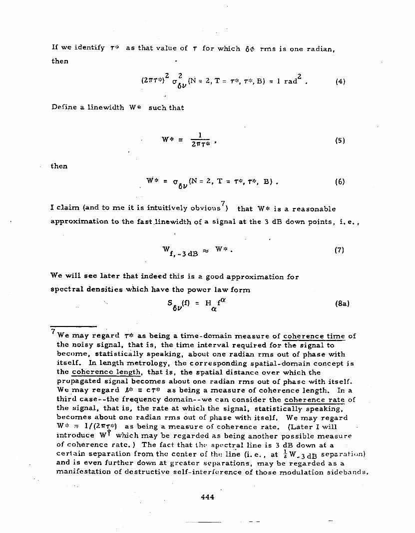
If we identify 7:: a s that value of r fo r which 66 rms i s one radian,
then
(4 ) (ZTT") 2 2 (T (N = 2, T = r&, r+, B) = 1 rad 2 . &V
Define a linewidth W* such that
then
7 I claim (and to me it is intuitively obvious ) that W4 is a reasonable
approximation to the fast .linewidth of a signal a t the 3 d B down points, i. e. ,
w + . Wf,-3dB
We will see la te r that indeed this is a good approximation for
spectral densities which have thc powcr law form
Sav(f) = H fa @a) CY
W e may regard 74 as being a time-domain measure of coherence t ime of the noisy signal, that is, the time interval required for the signal to become, statistically speaking, about one radian r m s out of phase with itself. In length metrology, the corresponding spatial-domain concept i s the coherencc length, that i s , the spatial distance over which the propagated signal becomes about one radian r m s out of phasc with itself. W e may regard a* a CT* as being a measure of coherence length. In a third case--the frequency domain--we can consider the coherence rate of the signal, that is, the rate at which the signal, statistically speaking, becomes about one radian r m s out of phase with itself. W:: 3 1/(27W::) as being a measure of coherence rate. (Later I will introduce W t which may be regarded as being another possible measure of coherence rate. ) The fact that the. spectral line is 3 dB down at a
and is even further down at greater separations, may be regarded as a mnni fc station of d e s tructive s e If - int e r f c! I ence of those modulation s idc ba nd s .
We may regard
ceriain separation from the ccnter of the: lin-e (i. e. , at 1 w-3 dB separation)
444
_____-
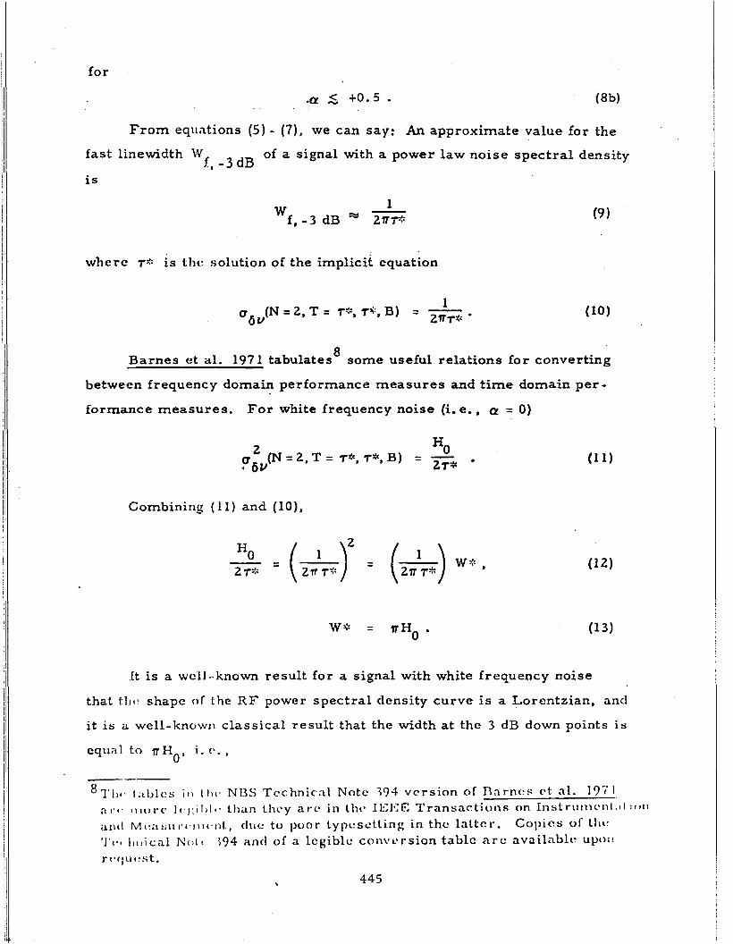
for
.Q! 5 +o. 5 . From equations (5) - (7)' we can say: An approx,mate value for the
fast linewidth W
is
of a signal with a power law noise spectral density f , - 3 dB
1 - f , - 3 dB 2nfl: w
wherc 7:: is thc. solution of the implicit equation
8 Barnes et al. 1971 tabulates some useful relations for converting
between frequency domain performance measures and time domain per -
formance measures. For white frequency noise (i.e. , a = 0)
2 HO pbV(N = 2, T = T*, T*, B) = - 2r*
Combining ( 1 1) and (IO),
.St is a wcll-known result for a signal with white frequency noise
that t l i c . shape of the R F power spectral density curve is a Lorentzian, and
it is a well-know11 classical result that the width at the 3 dB down points is
equal 1.0 n H i. e . , 0'
= nHo = T S Lorentziazl, - 3 dB 6 u
W
In the case of white frequency noise, m y concept of the fast linewidth and
the classical (i. e. , traditional) concept of linewidth a r e identical.
The approximate solution for the fast linewidth given by equations (9)
and (10) turns out to bc exact for the spccial case of whitc frequency noise,
but it is not quite exact for other power law spectral densities. Sections
III. D. 3 and 111. D. 6 give the more carefully derived results and their
comparison with these approximations.
2. One radian rms i n the frequency domain. Consider the spectral
density of the frequency fluctuations of the signal source.
density of the phase fluctuations is related exactly by the factor f
radians, i. e.,
The spectral - 2 square
Sag(f) = (1 rad 2 1 ) - S (f) . f2 6u
Define a linewidth W t such that the integral o f the phase noise spectral
density for all Fouricr noise frequencies greater than 2 Wf amounts to
one radian mean square, i. e.,
7 I claim (and to me it is intuitively obvious ) that Wf is a reasonable
approximation to thc fast linewidth of a signal at the 3 dB down points, 'i. c. ,
W e will see la tcr that indecd th is is a good approsimation for power law
spectral densities givcw by equatit)lls (8a) and (ab).
446
The approximate solution given by equations (16) and (17) is not
exaci for the case of white frequency noise, but it would be exact i f i n
equation (16) we were to require that the integral be set equal to 2 / n square
radians instead of being set equal to 1 square radian.
3. Modified Lorentzians of various orders : The width and shape
of the complete fas t RF power spectral line. In this third, more
detailed derivation, I will make a plausible assumption about the shape of
the complete fast RF power spectral line.
for the assumption, and then I will make some calculations of fast linewidths
that are exact relative to the assumption.
I will provide some justification
As already mentioned, for the case of a signal having white frequency 9 noise, its R F power spectral line has a Lorentzian shape, i. e.,
where, for the narrowband approximation (i. e., that u is much grea te r 0
-3 dB)' than W
a(a = 0) = - I ( )P, ' W-3dB
By studying thc behavior of Bessel functions, and applying that know1edg:c.
to the problem of relating phase modulation to sideband power, we can
easily decide some simple relations. We find for those sideband components
~
91x1 keeping \v i th t he coiistraint that I a m considering only good quality s i g n a l sources , I cxplicitly a m assuming that there a r e no amplitude modulation (AM) sidebands.
447
10 is much greater than the fast linewidth, i. e . , vo I for which I v -
that the sideband pvwcr is proportional to the square of the modulation
index,. that is, it is proportional to the square of the phase modulation
intensity. In a language which is more suitable for discussing random
noise, we find undcr the condition expressed by equation (21) that the fast
RF power spectral density'l at I v - v I from the center of the fast. line
is proportional to the spectral density'' of the phase noise at the Fourier
noise frequency f , with f equal to I v - vo 1 .
0
.
( v O f f ) = b P S ( f ) , (22) 'JRF Power 6(P
f = ( u - vo{ , (2 3)
and (25 1 1 - 2
2 b = constant = - rad .
- 2 That the coefficient b is equal to i rad can be derived using Bessel
functions, but it can also be derived from even simpler trigonometric
identities.
Combining equations (22) and (15) we see for
S6y(f) = H fm 01
This is equivalent to the condition that the modulation index be much smaller than unity, i. e., that the phase modulation is much less than one radian- -for the componcnts uncle 1- considcration:
Pleasc notc that i is in 1 3 n i . 1 1 ~ ~ ct al . 1071, I u s c one-sided spectral densities. spectral density as (vo f f ) to indicate and to remind us that, in the concept of thc h:it R F spcctral l in t> , the center of the fast line, is changing with t imc in tlw general case.
10
In cqii'ition (22) T writ<* 1 1 1 ~ . argunlcnt of thc fast R F powcr .
vO ,
44 8
for
f >> w f , -3dR (2 8)
We note that this is fclly in agrcemcnt with equations (18) and (19).
I now make an assumption about the shape of the fast RF power
spectral lines for power law spectral densities of frequency noise for cases
other than white frequency noise.
vious discussion, I assume that for a l l
Based on the insight gained in the pre-
a < + l o I
The shape function in equation (30) is a Lorentzian for OL equal to zero,
W e m a y call it a "modified Lorentzian of order (1 - case.
01)" for the general
I do not know whether or not equation (30) is in detail the correct
expression for the fast R F power spectral line. From the insight given by
equations (18) through (27), equation (30) is a plausible guess, and, even ii
incorrect, surcly it cannot be very far from being corrcct.
cquations (27) and (25) we see that equation (30) is cor rcc t for thc wings or
the fast linc, and the only possible discrepancy would IC in thc shapc at and
near tlic top of tlic fast linc.
noise cases which a r e under considcration, I do not expect any ''structure"
[othcr than thc srnooth form of equation (30) J would exist in the shape a t
and noar the top of the fast line.
From
For thc power law spectral density of frequency
449
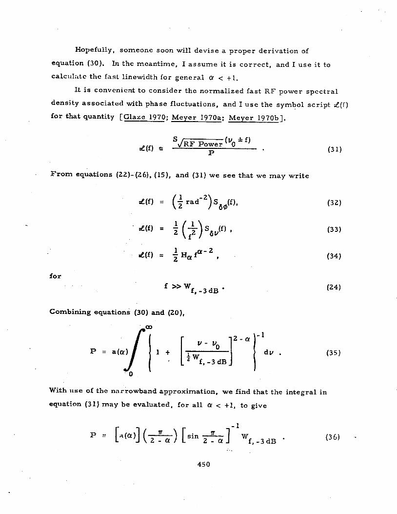
Hopefully, someone soon will devise a proper derivation of
equation (30).
calculate thc fast linewidth for general 01 < + l .
In the meantime, I assume it is correct , and I use it to
It is convcnicnt t o consider thc normalized fast R F power spcctral
density associated with phase fluctuations, and I use the symbol script f (J)
for that quantity [Glaze 1970; Meyer 1970a: Meyer 1970b 3.
. F r o m equations (22)-(26), (15), and (31) we see that we may write
Z(f) = (i rad-‘)S6@(f),
for
>> Wf, -3dB
Combining equations (30) and (20),
With use of the narrowband approximation, we find that the integral in
equation (31) may be evaluated, for all 01 e +1, to give
45 0
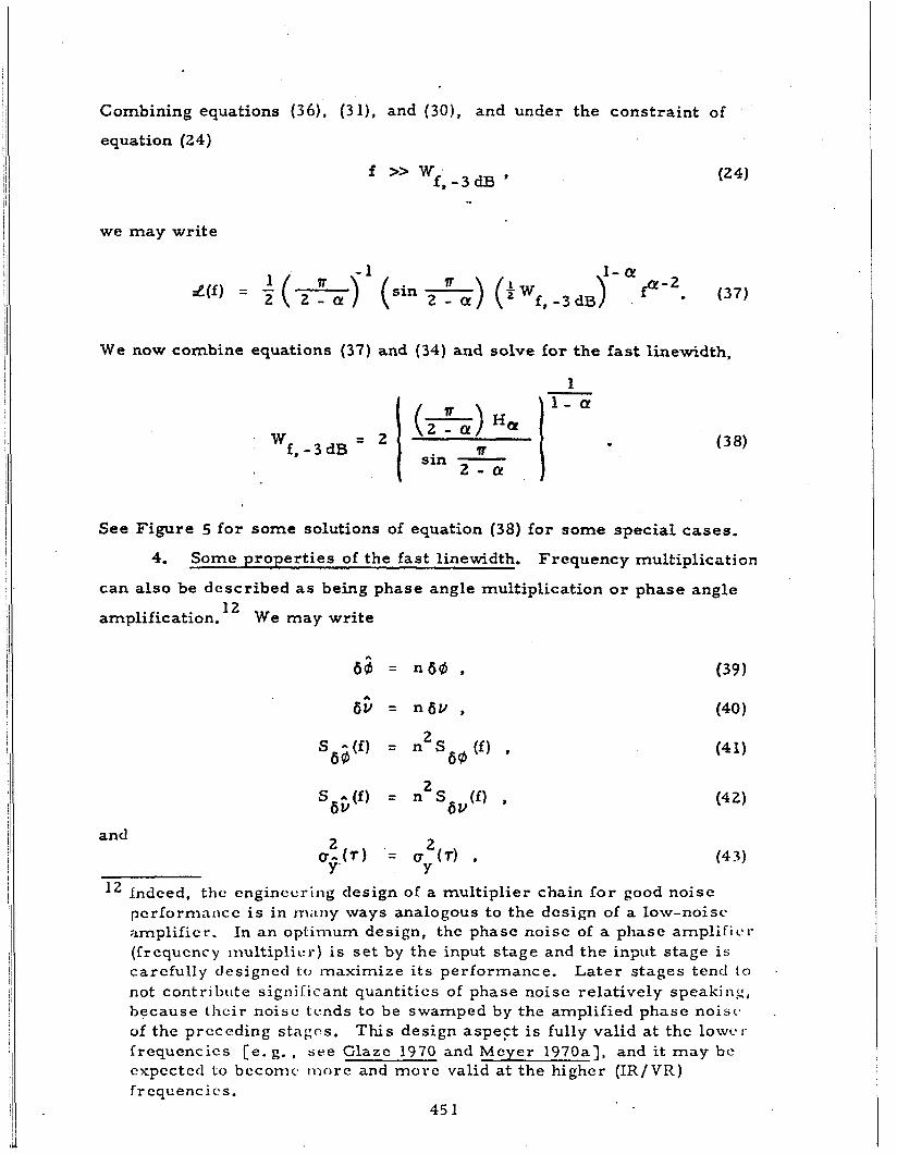
Combining equations ( 3 6 ) . (311, and (30), and under the constraint of
equation (24)
f > > W ' f , - 3 d B * I
we m a y write
- 1
f , -3 dB
W e now combine equations (37) and (34) and solve for the fast linewidth,
1
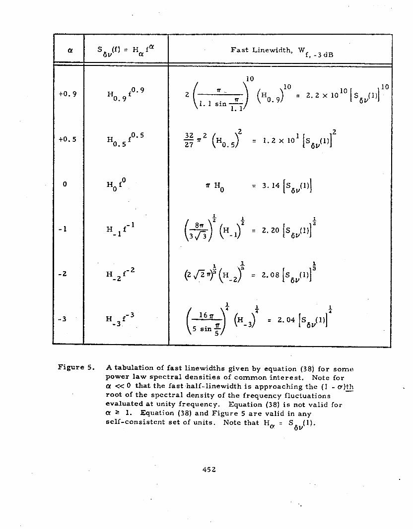
See Figure 5 for some solutions of equation (38) for some special cases.
4. Some properties of the fast linewidth. Frequency multiplication
can also be described as being phase angle multiplication or phase angle
amp1ification.l2 We m a y write
l2 Indced, the cnginccring design of a multiplier chain for good noisc pcrformnnce is in I T I ~ I I I Y ways analogous to the dcsign of a low-noisc amplifier. In an optimum design, thc phase noise of a phase amplific.1- (frequency niultiplicr) is set b y the input stage and the input stage is carcfully designcd t o maximize its performance. Later stages tend to not contribute significant quantities of phase noisc relatively speaking, because thcir noisc tcbnds to be swamped by the amplified phase noisc. of the prcccding stages. This design aspeFt is fully valid at thc 10wc.r frequencics [ e . g . , s e e Glaze 1970 and M c y e r 1970a], and it may bc cxpectctl to bcconic. more and morc valid at the higher ( IR/VR) frcqcencics.
45 1
- CY - -
to. 9
to. 5
0
- 1
* 2
3
H p. 9 0.9
fo. 5 Ho. 5
Ho fo
H f -2 -2
H 3f- 3 -
F a s t Linewidth, W f , - 3 d B
27
Ho = 3. 14 S (1) I b u 1 1 2 -
= 2.20 s (1) I 6 U 1
Figure 5. A tabulation of fast linewidths given by equation (38) for some power law spectral densities of common interest. 01 <e 0 that the fast .half-linewidth is approaching the ( I - a ) t h root of the spectral density of the frequency fluctuations evaluated at unity frequency. a! 2 1. self-consistent set of units. Note that H, = S
Note for
- Equation (38) is not valid for
Equation (38) and Figure 5 a r e valid in any (1).
6 V
452
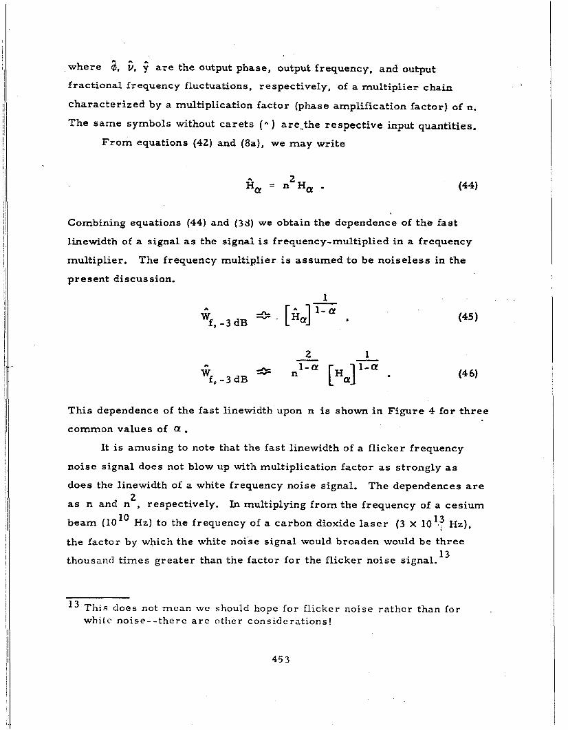
,where 2, c, $ are the output phase, output frequency, and output
fractional frequency fluctuations, respectively, of a multiplier chain
characterized b y a multiplication factor (phase amplification factor) of n.
The same symbols without carets (& ) are-the respective input quantities.
F r o m equations (42) and (8a), we may write
(44) 2 8, = n H, .
Combining equations (44) and (38) we obtain the dependence of the fast
linewidth of a signal as the signal is frequency-multiplied in a frequency
multiplier.
present discussion.
The frequency multiplier is assumed t o be noiseless in the
1
2 1
This dependence of the fast linewidth upon n is shown in Figure 4 for th ree
common values of Q . It is amusing to note that the fast linewidth of a flicker frequency
noise signal does not blow up with multiplication factor as strongly as
does the linewidth of a white frequency noise signal.
as n and n , respectively.
beam (10" Hz) to the frequency of a carbon dioxidc l a se r (3 x 10'*3 Hz),
the factor by which the white noise signal would broaden would be three
thousand times greater than the factor for the flicker noise signal.
The dependences are
In multiplying f rom the frequency of a cesium 2
1 3
l 3 This does not mean w c should hope for f l ickcr noise ra thcr than for whit c noise - - thcrc a r c otiie r con s i d e rations !
45 3
Another point of interest is that the fast linewidth of a flicker
frequency noise signal is proportional to the multiplication factor.
behavior is unique to the flicker noise case.
noises, only for flicker of frequency noise is the fractional linewidth of t h e
frequcncy-multiplied signal independent of the multiplication factor.
This
Of the various power law 14
5 . A graphical fast linewidth construction. It is possible to make a
graphical construction which gives a solution for the fast linewidth.
Figure 6.
revealing fashion the dependence of W upon the random noise level of the
signal source (c. g., a microwave oscillator), the dependence of W
the multiplication factor n, and the general way in which different power
laws for the phase noise spectral density affect Wf . "W locus" is drawn so that it passes through the point
See
Although only approximate, this graphical solution shows in a
f upon
f
h Figure 6 the
2 -1 f = 1 Hz; SsG(f) = -7 dB relative to 1 rad Hz ,
- 1 and so that it has a slope corresponding to f
density, S
the random phase noise at the n-th harmonic) and plotted. At some highest
frequency, f,, the random noise plot will c r o s s the W locus and be below it
for all higher f. Simply identify f as W and for typical random noises
encountered in good oscillators, this approximate value for W
co r rec t within a factor of two o r thereabouts. This is probably adequate
for preliminary engineering design of the frequency synthesis systems of
present inter c st.
. The phase noise spectral
(f) , of the output of the oscillator is multiplied by n2 (to give 68
X f will be f
The intercept of -7 dB is chosen to be cor rec t for flicker of frequency
noise (a = -l), and it is a good approximation for the other commonly-
encountcred noisc laws.
would bc only 2 tlR higher for white F M (a = 0) and would be only 2.5 dU
lower for randon1 walk FM noise.
For example, t o be exact the W locus intercept
- l4 Tlic case of flicker frccpency noise (a = -1) is common, and its siniylc
behavior unrl<*r frequency multiplication allows s o m e of the usual ca l c~~ i - lations concc*riiing noisc to be done easily in one's head.
45 4
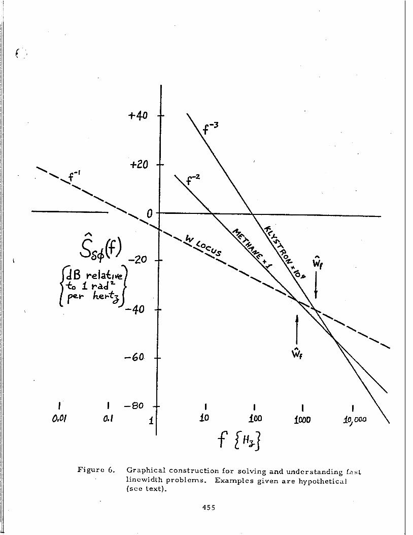
Figure 6. Graphical construction for solving and understanding fast lincwidth problems. ( s c e text).
Examples given a r e hypothetical
45 5
In Figure 6 I consider the hypothetical case of an X-band klystron
signal multiplied by a factor n of lo4 up to the frequency of the methane
device. I assume that the klystron signal has a flicker of frequency noise
of one part in 10 . That is , the N l a n variance for N = 2, T = 7, 7, and
B is
1 1
0 2 ( T ) = (1 X 10-l1f T o . Y
If multiplied t o 88 THz, the phase noise would be
(47 1
(49 1 5 2 2 - 3 S,,(f) = (5.7 X 10 rad Hz ) f ,
and
( 5 0 ) 4 n - 1 0 .
I also consider the hypothctical case of a methane device with direct
output at 88'THz. I assume the methane device has a white frequency noise 13 with a one-second stability of one par t in 10 . That is, the Allan variance
for N = 2, T = T, T, and B is
The phase noise of this mcthane signal is
2 2 - 2 s,$(f) = (1. 6 X 10 rat1 Hx) f ,
and n = 1..
45 6
Equations (49) and (52) are plotted in Figure 6. F rom t h ir intersection
with the W locus we obtain thq fast linewidths for the methane signal and
the multiplied klystron signal to be 680 Hz and 1700 Hz, respectively.
Using equation (38) [or Figure 53 the fast linewidths are calculated to be
500 Hz and 1700 Hz, respectively.
Since multiplication by a factor of ten, for example, would correspond
to a shift of 20'dB on F i g u r e 6, one can look at Figure 6 and quickly com-
prehend how the various fast linewidths would change i f the multiplication
factor were changed.
Although the discussion so f a r has been for pure power law spectral
densities, the graphical construction of Figure 6 can be used to estimate
the fast linewidth of signals whose spectral behavior is not as simple as a
pure power law.
6. Util i ty of W* and of WT as approximations to the fast linewidth
W -f The methods of calculation of W* and Wl involve the usual
frequency/time stability measures, and do not involve any measures of
radio frequency power. This simplification makes them easy to use in
noise calculations.
linewidth W
linewidth in noise calculations without being required to use explicitly R F
power spectral density mathematics.
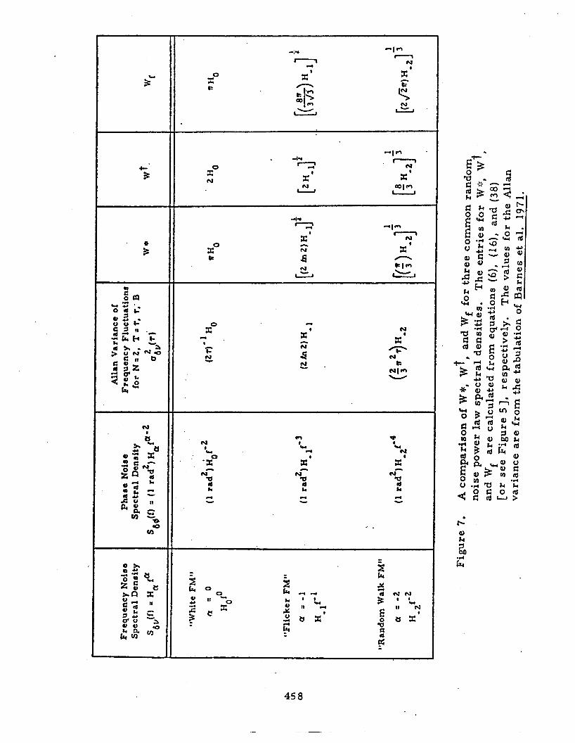
W*, W t , and W for three common random frequency noise power law
spectral densities.
for many engineering purposes.
If W:: and W i a r e adequate approximations to the fast
then we have an easy way to introduce the (approximate) fast f '
In Figure 7, I show a comparison of
f We can see that the approximation is sufficiently good
457
t 3
n
xo t
zo N
n N
X 8 u
X0 k
-1-4
-2 X '
2%
N
si
X0 8 n c
cu X '
N t
U CUI"
...
E o
i aJ I1
xo c,
45 8
IV. DISCUSSION
If the instabilities of all signal sources were merely white frequency
noise, then the mathematics of Section I11 would not be very relevant to
infrared-microwave frequency synthesis.
concept of the fast linewidth, for the linewidth of the signal would be
independent of the time interval we use to look a t the signal.
There would be no need for the
Conversely, i f the spectral density of the frequency fluctuations is
low-frequency divergent, then the longer the time interval T we use to
observe the radio-frequency power spectral linewidths W -3dB(rfP the . broader that linewidth will be.
frequency of the fast line. In principle, and in practice, it is
possible to build a servo to tune a superheterodyne receiver having a
narrowband IF amplifier to track such a moving signal. The bandwidth of
the IF amplifier must be la rger than the fast linewidth of the signal, but it
can be narrowed down toward that bandwidth as a limit.
This is the result of the moving around in
The stabilities of available X-band signal sources and 88-THz methane
devices a r e sufficiently good that we can conceive of frequency synthesis
designs to connect X-band with 88 TNz which could have IF amplifier noise
bandwidths in the 10 Hz range. See Figure 3. With the improvements
which a r e occurring in the stability of these signal sources, we can conceive
of optimum designs fo r the future in which the required noise bandwidth
might get clown to the 10
3
2 I-Iz range.
In order to siiccessfully utilize such a narrowband system, several
control systems will generally be needed, and special auxiliary filters will
be necdctl.
on the output of an X-band oscillator to filter off noise sidebands and
spurious signals which a r e hundreds of kilohertz from the center frequency
("carrier").
probably must be reduced by scrvoing it to the output of a multiplier chain
driven b y a state-of-the-art quartz crystal oscillator.
For example, it usually will be necessary to u s e passive fi l ters
The sccond-to- second instability of the X-band oscillator
The hour-to-hour
45 9
(and longe~r) instability probably must be reduced by servoing this X-band
system to a microwave atomic frequency standard, e, g . , a commercial
rubidium gas ce l l device.
Instead of actually servoing the frequency of the X-band oscillator,
it might Le easier and more effcctivc to servo the center frequency of one
of the IF amplifiers, as indicated in Figure 3.
If an idler oscillator is used in the frequency multiplication chain,
e. g., a t 10 THa, i ts relatively large instabilities will require careful
application of either o r both of the techniques just mentioned.
difficult to servo the frequency of the idler oscillator due to poor
tuneability, the alternate procedure of controlling the center frequency of
If it is
an IF amplifier becomes very attractive. In principle, thio would allow
the idler oscillator to be free-running and yet not contribute to the noise
of the measurement.’ In such a scheme the role of the idler oscillator
would be purely to supply the high power needed for good efficiency at an
intermediate stagc of the frequency multiplication chain.
The point of this filtering and servoing is to reduce the total quantity
of additive noise by minimizing the noise bandwidth of the IF amplifier.
If the beat signal power is sufficiently greater than the noise power in the
narrowband IF bandwidth, i t will be possible to do cycle counting by using
the zero-crossings of the beat signal.
t o achieve very high accuracy in the frequency synthesis, for the uncertainty
will tend to be of the fl-count type.
If this can be done, we will be able
JI cyclc counting cannot be done, then w e will have to acquire a
cer tain amount of patience and use power spectral density detection
techniques, as opposed to zero-crossing techniques, and we will have to
average for t imes long compared to the (linewidth)
useful mcasiircimcnts of the beat signal.
precision of thc frequency conipariscm will not be a s good as for cycle
counling, bill il can stiIl bc vcry good.
- 1 in order to make
The accuracy as well as the
460
I
There a r e many other signal processing t r icks which can be
employed in the "frequency measurement system" block and in the
various servo control systems.
frequency multiplication, then we can reduce the complexity of the
If we can achieve greater efficiency of
apparatus.
the apparatus, ' then we will be able to successfully use non-linear elements
of relatively low effic4;ioncy. An understanding of the fast linewidth allows us
to see morc clearly how the trade-off should go.
Conversely, if we a r e willing to increase the complexity of
The behavior of the fast linewidth under multiplication suggests that
we should be seriously searching for methods of IR/VR frequency division
as a superior alternative to frequency multiplication. If divide-by-two, o r
divide-by-n, flip-flop circuits (or any other type of frequency division
elements) could be achieved at the 88 THz frequency, the beat signal used
i n Figure 3 could be taken at a lower frequency. The fast linewidth of the
beat signal would be narrower than if the beat signal were taken at 88 THz,
and the IF bandwidth could be narrower.
4.
The ultimate extension of course would be, i f possible, to repeatedly
divide al l the way down to the lower frequency. I strongly suggest that
possibilities for partial or complete I R / V R frequency division be sought,
studied, and exploited.
Acknowledgement.
by Ms. Eddycc Helfrich from the outline, notes, and slides used in the
presentation of the talk at Quebec, and from a cassette recording which
was made at Quebec of the talk.
Ms. Helfrich and of Allan Risley and Helmut Hellwig arc deeply appreciatcd.
The basic material of ' this manuscript was assembled
The encouragemcnt and help of
* * *
46 1