Embed Size (px)
DESCRIPTION
Atmos 2.1 Administration Guide
Citation preview
EMC®
Atmos™
Version 2.1
Administrator’s GuideP/N 300-013-492REV 01
EMC Atmos Version 2.1 Administrator’s Guide2
Copyright © 2008 - 2012 EMC Corporation. All rights reserved. Published in the USA.
Published November, 2012
EMC believes the information in this publication is accurate as of its publication date. The information is subject to change without notice.
The information in this publication is provided as is. EMC Corporation makes no representations or warranties of any kind with respect to the information in this publication, and specifically disclaims implied warranties of merchantability or fitness for a particular purpose. Use, copying, and distribution of any EMC software described in this publication requires an applicable software license.
EMC2, EMC, and the EMC logo are registered trademarks or trademarks of EMC Corporation in the United States and other countries. All other trademarks used herein are the property of their respective owners.
For the most up-to-date regulatory document for your product line, go to the technical documentation and advisories section on the EMC online support website.

CONTENTS
Preface
Chapter 1 Overview
About Atmos............................................................................................... 20 Atmos architecture...................................................................................... 21
Atmos installation options .................................................................... 22Atmos front-end nodes.......................................................................... 24
Atmos and object access ............................................................................ 26About the Atmos Installable File System................................................ 27
Atmos system management tools ............................................................... 27 About tenants and subtenants .................................................................... 28 About policy................................................................................................ 29 About administrative roles .......................................................................... 29
Authentication of administrative roles................................................... 30 About Atmos editions ................................................................................. 31
Chapter 2 SecurityAdmin Basics
Overview..................................................................................................... 34 Logging in ................................................................................................... 34 Adding users to the SysAdmin role.............................................................. 35
Atmos SysAdmin naming rules .............................................................. 35Using local authentication..................................................................... 36Using remote authentication ................................................................. 37Configuring an LDAP server as a remote authentication source.............. 37
Removing a SysAdmin................................................................................. 40 Modifying SecurityAdmin information ......................................................... 40
Part 1 SysAdmin
Chapter 3 SysAdmin Basics
Overview..................................................................................................... 46 Logging in ................................................................................................... 46 Using the SysAdmin dashboard .................................................................. 47
About the Summary tab......................................................................... 48About the Performance tab.................................................................... 51
Working with RMGs and nodes.................................................................... 52About the Nodes tab ............................................................................. 53About the Status tab ............................................................................. 55About the Performance tab.................................................................... 56Viewing details for a node ..................................................................... 56About the Events tab ............................................................................. 57About the Disk & FS tab......................................................................... 58About the Node performance tab........................................................... 59
Modifying SysAdmin information ................................................................ 59 Replacing failed disks ................................................................................. 60
Ordering a disk...................................................................................... 60Returning the failed disk ....................................................................... 61
EMC Atmos Version 2.1 Administrator’s Guide 3
Contents
Precautions........................................................................................... 61Handling disks ...................................................................................... 63Replacing a failed disk on WS2-Series hardware ................................... 63Replacing a failed disk on G3 hardware................................................. 67
Chapter 4 Configuring the Atmos System
Configuring the system master serial number.............................................. 74 Configuring NTP (Network Time Protocol) .................................................... 74 Configuring DNS.......................................................................................... 76 Working with location groups...................................................................... 77
Listing location groups .......................................................................... 78Adding location groups ......................................................................... 79Modifying location groups..................................................................... 79Deleting location groups ....................................................................... 80
Configuring web services security settings (system-wide)............................ 80Configuring SSL certificates (system-wide) ............................................ 81Enabling/Disabling SSL (system-wide) .................................................. 81
Configuring data protection......................................................................... 82Configuring the maintenance scheduler ................................................ 82Configuring a federation target .............................................................. 85Configuring MDS remote replication ...................................................... 86
Chapter 5 Managing Tenants
About tenants ............................................................................................. 90Tenant namespace................................................................................ 90
Listing tenants ............................................................................................ 90 Creating tenants ......................................................................................... 91
Configuring an LDAP server as a remote authentication source.............. 92Configuring OpenLDAP for UID secret storage ........................................ 95Configuring AD for UID secret storage .................................................... 97Making the shared secret store highly available .................................... 98Managing an external shared secret store ............................................. 98
Renaming tenants....................................................................................... 99 Creating a TenantAdmin............................................................................ 100
Atmos TenantAdmin naming rules ....................................................... 100Assigning the TenantAdmin role using local authentication ................. 100Assigning the TenantAdmin role using remote authentication ............. 102
Deleting a TenantAdmin............................................................................ 103 Assigning access nodes to a tenant .......................................................... 104 Modifying access node assignments......................................................... 106 Removing access node assignments ......................................................... 106 Enable/Disable SSL for tenant-level web service connections ................... 107 Configuring SSL certificates for a tenant.................................................... 107 Restricting Subtenant/UID data operations ............................................... 109
Restricting Subtenants or UIDs to read and delete operations ............. 109Restricting UIDs to read-only operations.............................................. 110Error Codes ......................................................................................... 111
Chapter 6 System Monitoring, Events, & Reporting
Overview................................................................................................... 114 Notification policy..................................................................................... 114
Testing notifications............................................................................ 115
4 EMC Atmos Version 2.1 Administrator’s Guide
Contents
Email notifications .................................................................................... 116 Monitoring Atmos with your NMS .............................................................. 117
SNMP support ..................................................................................... 117SNMP traps ......................................................................................... 118Dell traps ............................................................................................ 118SNMP agent ........................................................................................ 119Configuring SNMP ............................................................................... 120Getting useful data from the MIBs ....................................................... 121
System reports.......................................................................................... 128Configuring system reports.................................................................. 128SYR symptom codes............................................................................ 130Collecting system reports .................................................................... 137
Log files and log collection........................................................................ 138 Remote log files ........................................................................................ 139 Monitoring events..................................................................................... 140 Troubleshooting disk management events ................................................ 143
DM_FAILED_PARTITION_EVT ................................................................ 144DM_FAILED_FORMAT_EVT.................................................................... 144DM_DISK_UNAVAILABLE...................................................................... 144DM_DAE_UNAVAILABLE....................................................................... 144DM_DISK_ERROR................................................................................. 145DM_MOUNT_FAILED ............................................................................ 145DM_UUIDS_NOT_FOUND ..................................................................... 145DM_FILESYSTEM_NOT_IN_USE ............................................................ 146
Chapter 7 Getting Performance Data
Overview................................................................................................... 148 Example: Getting the statistics.................................................................. 148 Example: Resetting the counters ............................................................... 150
Part 2 TenantAdmin
Chapter 8 TenantAdmin Basics
Overview................................................................................................... 154 Logging in ................................................................................................. 154 Using the Tenant Dashboard ..................................................................... 156 Modifying TenantAdmin Information ......................................................... 157 Quick reference......................................................................................... 157
Configuring policies ............................................................................ 157Configuring web services, CIFS, NFS, or Atmos CAS access .................. 158
Chapter 9 Managing Subtenants
About subtenants ..................................................................................... 162Subtenant namespace ........................................................................ 162
Listing subtenants .................................................................................... 163 Creating subtenants.................................................................................. 163 Renaming subtenants ............................................................................... 163 Managing SubtenantAdmins..................................................................... 164
Creating a Subtenant Admin................................................................ 164Deleting a SubtenantAdmin................................................................. 166
Managing Subtenant Resources................................................................ 166Creating a UID and shared secret......................................................... 168
EMC Atmos Version 2.1 Administrator’s Guide 5
Contents
Configuring CIFS access nodes ............................................................ 169Configuring NFS access nodes............................................................. 176
Setting up CAS Policy-Driven Storage ........................................................ 178CAS Administrator Tasks ..................................................................... 178Creating a PEA file for accessing Atmos CAS ........................................ 179About CAS Metadata ........................................................................... 182Registering Tags.................................................................................. 184Reordering policy selectors ................................................................. 187Assigning a default policy ................................................................... 187Monitoring CAS ................................................................................... 188CAS troubleshooting ........................................................................... 189
Chapter 10 Managing Policies
About policy.............................................................................................. 192Atmos policy components ................................................................... 192When is a policy applied to an object?................................................. 193Policy evaluation................................................................................. 193About the default policy ...................................................................... 193
Working with policy specifications ............................................................ 194Metadata location ............................................................................... 195Replicas .............................................................................................. 195Server Attributes ................................................................................. 198Striping ............................................................................................... 200GeoParity ............................................................................................ 200Retention/Deletion.............................................................................. 202
Working with policy selectors.................................................................... 203Assigning policy selectors to subtenants............................................. 207
Working with policy transition specifications ............................................ 208Defining a policy transition specification ............................................. 209Defining multi-path policy transitions.................................................. 212Policy transitions and Retention/Deletion ........................................... 213Removing a single transition ............................................................... 214Policy transition icons ......................................................................... 214About lock time on exit........................................................................ 215How user-defined and automated policy transition policies interact .... 215Policy transition limitations................................................................. 216
Policy example.......................................................................................... 217Creating the Production policy............................................................. 217Creating the Archive Policy .................................................................. 218Creating the FinalArchive Policy........................................................... 218Creating a Policy Selector .................................................................... 218Automating the object lifecycle by using a policy transition specification ... 219
Part 3 SubtenantAdmin
Chapter 11 SubtenantAdmin Basics
Overview................................................................................................... 226 Using the SubTenant Dashboard............................................................... 227 Working with UIDs and shared secrets ...................................................... 228 Configuring access nodes for NFS ............................................................. 229 Configuring Access Nodes for CIFS ............................................................ 232
Adding or Editing a CIFS Share ............................................................ 232
6 EMC Atmos Version 2.1 Administrator’s Guide

Contents
Reordering policy selectors ....................................................................... 234
Part 4 Appendices
Appendix A Atmos Event Reference
Appendix B Atmos MIB
Atmos MIB Version Group ......................................................................... 268atmosMibMajorVersion ....................................................................... 268atmosMibMinorVersion....................................................................... 268
Atmos Software Version Group.................................................................. 268atmosVersion...................................................................................... 268
Atmos Capacity Group............................................................................... 268atmosNodeCapacityStorageCapacity................................................... 268atmosNodeCapacityStorageCapacityUnit ............................................ 268atmosNodeCapacityStorageUsed ........................................................ 268atmosNodeCapacityStorageUsedUnit.................................................. 268atmosNodeCapacityStorageAvailable.................................................. 269atmosNodeCapacityStorageAvailableUnit ........................................... 269atmosNodeCapacityStoragePercentUsed............................................. 269atmosNodeCapacityMetadataCapacity ................................................ 269atmosNodeCapacityMetadataCapacityUnit.......................................... 269atmosNodeCapacityMetadataUsed ..................................................... 269atmosNodeCapacityMetadataUsedUnit ............................................... 269atmosNodeCapacityMetadataAvailable............................................... 269atmosNodeCapacityMetadataAvailableUnit......................................... 269atmosNodeCapacityMetadataPercentUsed.......................................... 270atmosNodeCapacityDataCapacity........................................................ 270atmosNodeCapacityDataCapacityUnit ................................................. 270atmosNodeCapacityDataUsed............................................................. 270atmosNodeCapacityDataUsedUnit....................................................... 270atmosNodeCapacityDataAvailable ...................................................... 270atmosNodeCapacityDataAvailableUnit ................................................ 270atmosNodeCapacityDataPercentUsed ................................................. 270
Atmos Service Status Group...................................................................... 271atmosServiceActiveEntries .................................................................. 271atmosServiceTable.............................................................................. 271
Atmos Metadata Service Group ................................................................. 272atmosMDSUpmasterCount .................................................................. 272atmosMDSContainerCount .................................................................. 272atmosMDSReplicaGroupCount ............................................................ 272
Atmos Storage Service Group.................................................................... 272atmosSSDestageStatus....................................................................... 272
Atmos Job Service Group........................................................................... 272atmosJSQueueStatus (obsolete).......................................................... 272atmosJSQueueLength.......................................................................... 272atmosJSRecoverQueueLength.............................................................. 272atmosJSRecoverDequeueRate ............................................................. 273atmosJSRecoverByteRate .................................................................... 273atmosJSReclaimQueueLength ............................................................. 273atmosJSReclaimDequeueRate ............................................................. 273atmosJSReclaimByteRate .................................................................... 273atmosJSReplicateQueueLength ........................................................... 273
EMC Atmos Version 2.1 Administrator’s Guide 7

Contents
atmosJSReplicateDequeueRate ........................................................... 273atmosJSReplicateByteRate .................................................................. 273atmosJSVerifyQueueLength ................................................................. 273atmosJSVerifyDequeueRate................................................................. 274atmosJSVerifyByteRate ........................................................................ 274atmosJSDatamigrationStatus .............................................................. 274atmosJSReclaimStatus ........................................................................ 274atmosJSRecoverStatus ........................................................................ 274atmosJSReplicateStatus ...................................................................... 274atmosJSRescanStatus ......................................................................... 274atmosJSUpgradeStatus ....................................................................... 274atmosJSVerifyStatus............................................................................ 274atmosJSDatamigrationQueueLength.................................................... 275atmosJSUpdateQueueLength .............................................................. 275atmosJSRescanQueueLength............................................................... 275
Atmos Web Service Group......................................................................... 275atmosWSReadsPerSec ........................................................................ 275atmosWSWritesPerSec ........................................................................ 275atmosWSDeletesPerSec ...................................................................... 275atmosWSTransPerSec ......................................................................... 275
Atmos Notification Group.......................................................................... 275atmosNotificationVariables ................................................................. 275atmosNotificationCpuUsage................................................................ 276atmosNotificationMemoryUsage ......................................................... 276atmosNotificationSwapUsage ............................................................. 276atmosNotificationFilesystemUsage...................................................... 276atmosNotificationServiceMemoryUsage .............................................. 277atmosNotificationServiceStatus .......................................................... 277atmosNotificationInternalCarrierStatus (obsolete)............................... 277atmosNotificationExternalCarrierStatus (obsolete) .............................. 277atmosNotificationNodeStatus ............................................................. 277atmosNotificationSegmentStatus........................................................ 277atmosNotificationRMGStatus .............................................................. 277atmosNotificationPolicySyncFailed...................................................... 277atmosNotificationUidSyncFailed.......................................................... 277atmosNotificationDAEStatus (obsolete)............................................... 278atmosNotificationDAEBackplaneStatus (obsolete) .............................. 278atmosNotificationDAEFanStatus (obsolete) ......................................... 278atmosNotificationDAETempStatus (obsolete) ...................................... 278atmosNotificationDiskStatus (obsolete) .............................................. 278atmosNotificationPolicyResourceStatus .............................................. 278atmosNotificationMgmtDBStatus (obsolete)........................................ 278atmosNotificationDiskRecovery (obsolete) .......................................... 278atmosNotificationVIPFailover .............................................................. 278atmosNotificationMDSJobFallBehind................................................... 278atmosNotificationMDSSetAccessErr .................................................... 279atmosNotificationNTPClockSourceErr (obsolete) ................................. 279atmosNotificationNTPClockSyncErr ..................................................... 279atmosNotificationMDSInitStatus ......................................................... 279atmosNotificationMDSSyncStatus (obsolete) ...................................... 279atmosNotificationServiceCoreFileCreated............................................ 279atmosNotificationGuiConfiguration ..................................................... 279atmosNotificationGuiAdministrator ..................................................... 279atmosNotificationGuiSubtenantConfig ................................................ 280atmosNotificationGuiTenantConfig...................................................... 280
8 EMC Atmos Version 2.1 Administrator’s Guide

Contents
atmosNotificationGuiSecurityOperation .............................................. 280atmosNotificationGuiMdsConfig.......................................................... 280atmosNotificationGuiOperation........................................................... 280atmosNotificationUpgradeStatus ........................................................ 280atmosNotificationUpdateStatus .......................................................... 280atmosNotificationJSScan..................................................................... 280atmosNotificationCasConfiguration..................................................... 280atmosNotificationCasStatus................................................................ 281atmosNotificationDiskPartition............................................................ 281atmosNotificationFilesystemStatus ..................................................... 281atmosNotificationFilesystemProvisioned............................................. 281atmosNotificationPostgresqlConnStatus ............................................. 281atmosNotificationMaintenanceMode................................................... 281atmosNotificationPostgresConnectionCount ....................................... 281atmosNotificationPostgresDBFailover.................................................. 281atmosNotificationMetadataDiskUtilization .......................................... 281atmosNotificationWebserviceHttpWorkerCrash ................................... 282atmosNotificationCifsAdsReconfiguration ........................................... 282atmosNotificationCasProfileStatus ...................................................... 282atmosNotificationDiskStatusEvent ...................................................... 282atmosNotificationDiskConfigurationFailure ......................................... 282atmosNotificationDiskUnavailable ...................................................... 282atmosNotificationDaeUnavailable ....................................................... 282atmosNotificationDiskError ................................................................. 282atmosNotificationDaeStatus ............................................................... 282atmosNotificationSSCapacityUsage .................................................... 283atmosNotificationDiskRecoveryEvent .................................................. 283atmosNotificationMountPointStatus.................................................... 283atmosNotificationDiskIndexError ......................................................... 283atmosNotificationCoreFiles ................................................................. 283atmosNotificationDaeError .................................................................. 283atmosNotificationFilesystemNotUsed.................................................. 283atmosNotificationDiskMoved .............................................................. 283atmosNotificationMdsSetCreationError ............................................... 283atmosNotificationMdsInsufficientDisk................................................. 284atmosNotificationDirtyDiskCleanup..................................................... 284atmosNotificationSystemDiskUtilization ............................................. 284atmosNotificationDuplicateResource .................................................. 284atmosNotificationDiskReplaceableStatus............................................ 284atmosNotificationMdsTransactionConflict ........................................... 284atmosNotificationMdsBdbPanic .......................................................... 284atmosNotificationMdsSaveRollback .................................................... 284atmosNotificationMdsMasterToSlave .................................................. 284atmosNotificationMdsDbMasterLeaseExpired ..................................... 285atmosNotificationCMFUpdateCfgFailed ............................................... 285atmosNotificationInstallStatus ............................................................ 285atmosNotificationSSLatency ............................................................... 285atmosNotificationSSDestageStatus..................................................... 285atmosNotificationSSProxyLatency ....................................................... 285atmosNotificationRmsLatency ............................................................. 285atmosNotificationMdlsLatency ............................................................ 285atmosNotificationJSLatency................................................................. 285atmosNotificationJSQueueStatus ........................................................ 286atmosNotificationJSQueueLatency ...................................................... 286atmosNotificationCCLatency ............................................................... 286
EMC Atmos Version 2.1 Administrator’s Guide 9

Contents
atmosNotificationAuthSrvLatency ....................................................... 286atmosNotificationNoDiskFound........................................................... 286atmosNotificationNetworkInterfaceStatus ........................................... 286atmosNotificationLockboxError ........................................................... 286atmosNotificationMDSConversionPaused ........................................... 286atmosNotificationDiskMarkedSuspect ................................................ 286atmosNotificationFilesysDevPathChanged .......................................... 287atmosNotificationSvrFanSpeedStatus ................................................. 287atmosNotificationSvrFanRedundancyStatus ........................................ 287atmosNotificationSvrFanStatus ........................................................... 287atmosNotificationSvrBatteryStatus...................................................... 287atmosNotificationSvrPSRedundancy ................................................... 287atmosNotificationSvrPSStatus............................................................. 287atmosNotificationSvrControllerStatus ................................................. 287atmosNotificationSvrChannelStatus.................................................... 288atmosNotificationSvrVirtDiskStatus..................................................... 288atmosNotificationSvrDiskArrayStatus.................................................. 288atmosNotificationSvrTempStatus ........................................................ 288
Atmos Group Conformance Information .................................................... 288atmosMibVersionGroup ...................................................................... 288atmosSoftwareVersionGroup............................................................... 288atmosNodeCapacityGroup................................................................... 288atmosServiceGroup............................................................................. 288atmosMetadataServiceGroup .............................................................. 289atmosStorageServiceGroup................................................................. 289atmosJobServiceGroup........................................................................ 289atmosWebServiceGroup...................................................................... 289atmosNotificationVariableGroup ......................................................... 289atmosNotificationGroup ...................................................................... 289atmosObsolete ................................................................................... 289
Atmos Compliance Information ................................................................. 289atmosCompliance ............................................................................... 289
Appendix C MIB-II (RFC 1213)
MIB II overview.......................................................................................... 292 Textual conventions.................................................................................. 292 Objects and types imported ...................................................................... 293 System group............................................................................................ 293
sysDescr ............................................................................................. 293sysObjectID......................................................................................... 293sysUpTime .......................................................................................... 293sysContact .......................................................................................... 293sysName ............................................................................................. 294sysLocation......................................................................................... 294sysServices ......................................................................................... 294
Interfaces group........................................................................................ 294ifNumber............................................................................................. 294ifTable................................................................................................. 294ifEntry ................................................................................................. 295ifIndex................................................................................................. 296ifDescr ................................................................................................ 296ifType.................................................................................................. 296ifMtu ................................................................................................... 296ifSpeed ............................................................................................... 296
10 EMC Atmos Version 2.1 Administrator’s Guide

Contents
ifPhysAddress ..................................................................................... 296ifAdminStatus ..................................................................................... 296ifOperStatus........................................................................................ 297ifLastChange ....................................................................................... 297ifInOctets ............................................................................................ 297ifInUcastPkts....................................................................................... 298ifInNUcastPkts .................................................................................... 298ifInDiscards......................................................................................... 298ifInErrors ............................................................................................. 298ifInUnknownProtos.............................................................................. 298ifOutOctets.......................................................................................... 299ifOutUcastPkts .................................................................................... 299ifOutNUcastPkts.................................................................................. 299ifOutDiscards ...................................................................................... 299ifOutErrors........................................................................................... 299ifOutQLen............................................................................................ 300ifSpecific............................................................................................. 300
AT Group................................................................................................... 300atTable................................................................................................ 300atEntry ................................................................................................ 300atIfIndex.............................................................................................. 300atPhysAddress .................................................................................... 300atNetAddress ...................................................................................... 301
IP group .................................................................................................... 301ipForwarding ....................................................................................... 301ipDefaultTTL ........................................................................................ 301ipInReceives........................................................................................ 301ipInHdrErrors....................................................................................... 301ipInAddrErrors..................................................................................... 302ipForwDatagrams ................................................................................ 303ipInUnknownProtos............................................................................. 303ipInDiscards........................................................................................ 303ipInDelivers......................................................................................... 303ipOutRequests .................................................................................... 303ipOutDiscards ..................................................................................... 303ipOutNoRoutes.................................................................................... 303ipReasmTimeout ................................................................................. 304ipReasmReqds .................................................................................... 304ipReasmOKs........................................................................................ 304ipReasmFails....................................................................................... 305ipFragOKs ........................................................................................... 305ipFragFails........................................................................................... 305ipFragCreates ...................................................................................... 305ipAddrTable ........................................................................................ 305ipAddrEntry ......................................................................................... 306ipAdEntAddr........................................................................................ 306ipAdEntIfIndex .................................................................................... 306ipAdEntNetMask ................................................................................. 306ipAdEntBcastAddr ............................................................................... 306ipAdEntReasmMaxSize........................................................................ 307ipRouteTable....................................................................................... 307ipRouteEntry ....................................................................................... 307ipRouteDest ........................................................................................ 307ipRouteIfIndex..................................................................................... 307ipRouteMetric1 ................................................................................... 308
EMC Atmos Version 2.1 Administrator’s Guide 11
Contents
ipRouteMetric2 ................................................................................... 308ipRouteMetric3 ................................................................................... 308ipRouteMetric4 ................................................................................... 308ipRouteNextHop.................................................................................. 308ipRouteType ........................................................................................ 308ipRouteProto ....................................................................................... 309ipRouteAge ......................................................................................... 309ipRouteMask....................................................................................... 309ipRouteMetric5 ................................................................................... 309ipRouteInfo ......................................................................................... 309ipNetToMediaTable ............................................................................. 310ipNetToMediaEntry.............................................................................. 310ipNetToMediaIfIndex ........................................................................... 310ipNetToMediaPhysAddress.................................................................. 310ipNetToMediaNetAddress.................................................................... 310ipNetToMediaType .............................................................................. 310ipRoutingDiscards............................................................................... 310
ICMP group ............................................................................................... 311icmpInMsgs ........................................................................................ 311icmpInErrors........................................................................................ 311icmpInDestUnreachs ........................................................................... 311icmpInTimeExcds ................................................................................ 311icmpInParmProbs................................................................................ 312icmpInSrcQuenchs .............................................................................. 312icmpInRedirects .................................................................................. 312icmpInEchos ....................................................................................... 312icmpInEchoReps ................................................................................. 312icmpInTimestamps.............................................................................. 312icmpInTimestampReps........................................................................ 312icmpInAddrMasks ............................................................................... 312icmpInAddrMaskReps ......................................................................... 312icmpOutMsgs...................................................................................... 313icmpOutErrors ..................................................................................... 313icmpOutDestUnreachs ........................................................................ 313icmpOutTimeExcds.............................................................................. 313icmpOutParmProbs ............................................................................. 313icmpOutSrcQuenchs ........................................................................... 313icmpOutRedirects................................................................................ 313icmpOutEchos..................................................................................... 313icmpOutEchoReps............................................................................... 314icmpOutTimestamps ........................................................................... 314icmpOutTimestampReps ..................................................................... 314icmpOutAddrMasks............................................................................. 314icmpOutAddrMaskReps....................................................................... 314
TCP group ................................................................................................. 314tcpRtoAlgorithm .................................................................................. 314tcpRtoMin ........................................................................................... 314tcpRtoMax........................................................................................... 315tcpMaxConn........................................................................................ 315tcpActiveOpens................................................................................... 315tcpPassiveOpens ................................................................................ 315tcpAttemptFails................................................................................... 315tcpEstabResets ................................................................................... 315tcpCurrEstab ....................................................................................... 315tcpInSegs............................................................................................ 316
12 EMC Atmos Version 2.1 Administrator’s Guide
Contents
tcpOutSegs ......................................................................................... 316tcpRetransSegs ................................................................................... 316TCP Connection Table.......................................................................... 316tcpConnTable...................................................................................... 316tcpConnEntry ...................................................................................... 316tcpConnState ...................................................................................... 316tcpConnLocalAddress ......................................................................... 317tcpConnLocalPort ................................................................................ 317tcpConnRemAddress........................................................................... 317tcpConnRemPort ................................................................................. 317tcpInErrs ............................................................................................. 317tcpOutRsts .......................................................................................... 317
UDP group ................................................................................................ 317udpInDatagrams ................................................................................. 317udpNoPorts......................................................................................... 318udpInErrors ......................................................................................... 318udpOutDatagrams............................................................................... 318udpTable............................................................................................. 318udpEntry ............................................................................................. 318udpLocalAddress ................................................................................ 318udpLocalPort....................................................................................... 318
EGP group................................................................................................. 318egpInMsgs .......................................................................................... 318egpInErrors ......................................................................................... 319egpOutMsgs........................................................................................ 319egpOutErrors....................................................................................... 319egpNeighTable .................................................................................... 319egpAs.................................................................................................. 321
Transmission group .................................................................................. 321 SNMP group.............................................................................................. 322
snmpInPkts......................................................................................... 322snmpOutPkts ...................................................................................... 322snmpInBadVersions ............................................................................ 322snmpInBadCommunityNames ............................................................. 322snmpInBadCommunityUses ................................................................ 323snmpInASNParseErrs........................................................................... 323snmpInTooBigs ................................................................................... 323snmpInNoSuchNames......................................................................... 323snmpInBadValues............................................................................... 323snmpInReadOnlys ............................................................................... 324snmpInGenErrs ................................................................................... 324snmpInTotalReqVars ........................................................................... 324snmpInTotalSetVars ............................................................................ 324snmpInGetRequests............................................................................ 324snmpInGetNexts ................................................................................. 324snmpInSetRequests ............................................................................ 324snmpInGetResponses ......................................................................... 325snmpInTraps ....................................................................................... 325snmpOutTooBigs................................................................................. 325snmpOutNoSuchNames ...................................................................... 325snmpOutBadValues ............................................................................ 325snmpOutGenErrs................................................................................. 325snmpOutGetRequests ......................................................................... 325snmpOutGetNexts............................................................................... 325snmpOutSetRequests ......................................................................... 326
EMC Atmos Version 2.1 Administrator’s Guide 13

Contents
snmpOutGetResponses....................................................................... 326snmpOutTraps .................................................................................... 326snmpEnableAuthenTraps .................................................................... 326
Appendix D Host Resources MIB (RFC 2790)
Host Resources System Group .................................................................. 328hrSystemUptime ................................................................................. 328hrSystemDate ..................................................................................... 328hrSystemInitialLoadDevice.................................................................. 328hrSystemInitialLoadParameters........................................................... 328hrSystemNumUsers............................................................................. 328hrSystemProcesses ............................................................................. 328hrSystemMaxProcesses ...................................................................... 328
Host Resources Storage Group.................................................................. 329hrStorageTypes ................................................................................... 329hrMemorySize ..................................................................................... 330hrStorageTable.................................................................................... 330
Host Resources Device Group ................................................................... 331hrDeviceTypes..................................................................................... 332hrDeviceTable ..................................................................................... 333hrProcessorTable ................................................................................ 335hrNetworkTable................................................................................... 335hrPrinterTable ..................................................................................... 336hrDiskStorageTable............................................................................. 337hrPartitionTable .................................................................................. 337hrFSTable............................................................................................ 338hrFSTypes ........................................................................................... 340
Host Resources Running Software Group................................................... 342hrSWOSIndex...................................................................................... 342hrSWRunTable .................................................................................... 342
Host Resources Running Software Performance Group .............................. 343hrSWRunPerfTable .............................................................................. 343
Host Resources Installed Software Group.................................................. 344hrSWInstalledLastChange ................................................................... 344hrSWInstalledLastUpdateTime ............................................................ 344hrSWInstalledTable ............................................................................. 345
Conformance information ......................................................................... 345hostResourcesMibModule................................................................... 345hrMIBCompliances.............................................................................. 345hrMIBGroups....................................................................................... 346
Glossary
Index
14 EMC Atmos Version 2.1 Administrator’s Guide
PREFACE
As part of an effort to improve its product lines, EMC periodically releases revisions of its software and hardware. Therefore, some functions described in this document might not be supported by all versions of the software or hardware currently in use. The product release notes provide the most up-to-date information on product features.
Contact your EMC representative if a product does not function properly or does not function as described in this document.
Note: This document was accurate at publication time. New versions of this document might be released on the EMC online support website. Check the EMC online support website to ensure that you are using the latest version of this document.
AudienceThis document is part of the Atmos documentation set, and is intended for use by system administrators who are responsible for configuring and maintaining Atmos.
Related documentationThe EMC Atmos documentation set includes the following titles:
◆ EMC Atmos Release Notes
◆ EMC Atmos Administrator’s Guide
◆ EMC Atmos Programmer’s Guide
◆ EMC Atmos System Management API Guide
◆ EMC Atmos Security Configuration Guide
◆ EMC Atmos CAS Programmer’s Guide
◆ EMC Atmos CAS API Reference Guide
◆ EMC Atmos online help
◆ EMC Atmos Series Open Source License and Copyright Information
◆ EMC Atmos Series Open Source License and Copyright Information for GPLv3
Conventions used in this documentEMC uses the following conventions for special notices:
Note: A note presents information that is important, but not hazard-related.
IMPORTANT
An important notice contains information essential to software or hardware operation.
EMC Atmos Version 2.1 Administrator’s Guide 15

Preface
Typographical conventions
EMC uses the following type style conventions in this document:
Where to get helpEMC support, product, and licensing information can be obtained as follows:
Product information - For documentation, release notes, software updates, or information about EMC products, go to EMC Online Support at:
https://support.emc.com
Technical support - Go to EMC Online Support and click Service Center. You will see several options for contacting EMC Technical Support. Note that to open a service request, you must have a valid support agreement. Contact your EMC sales representative for details about obtaining a valid support agreement or with questions about your account.
Normal Used in running (nonprocedural) text for:• Names of interface elements, such as names of windows, dialog boxes,
buttons, fields, and menus• Names of resources, attributes, pools, Boolean expressions, buttons,
DQL statements, keywords, clauses, environment variables, functions, and utilities
• URLs, pathnames, filenames, directory names, computer names, links, groups, service keys, file systems, and notifications
Bold Used in running (nonprocedural) text for names of commands, daemons, options, programs, processes, services, applications, utilities, kernels, notifications, system calls, and man pages
Used in procedures for:• Names of interface elements, such as names of windows, dialog boxes,
buttons, fields, and menus• What the user specifically selects, clicks, presses, or types
Italic Used in all text (including procedures) for:• Full titles of publications referenced in text• Emphasis, for example, a new term• Variables
Courier Used for:• System output, such as an error message or script• URLs, complete paths, filenames, prompts, and syntax when shown
outside of running text
Courier bold Used for specific user input, such as commands
Courier italic Used in procedures for:• Variables on the command line• User input variables
< > Angle brackets enclose parameter or variable values supplied by the user
[ ] Square brackets enclose optional values
| Vertical bar indicates alternate selections — the bar means “or”
{ } Braces enclose content that the user must specify, such as x or y or z
... Ellipses indicate nonessential information omitted from the example
16 EMC Atmos Version 2.1 Administrator’s Guide

Preface
Your commentsYour suggestions will help us continue to improve the accuracy, organization, and overall quality of the user publications. Send your opinions of this document to:
EMC Atmos Version 2.1 Administrator’s Guide 17

Preface
18 EMC Atmos Version 2.1 Administrator’s Guide
CHAPTER 1Overview
This chapter includes the following sections:
◆ About Atmos ........................................................................................................... 20◆ Atmos architecture.................................................................................................. 21◆ Atmos and object access ........................................................................................ 26◆ Atmos system management tools ........................................................................... 27◆ About tenants and subtenants ................................................................................ 28◆ About policy............................................................................................................ 29◆ About administrative roles ...................................................................................... 29◆ About Atmos editions ............................................................................................. 31
Overview 19
Overview
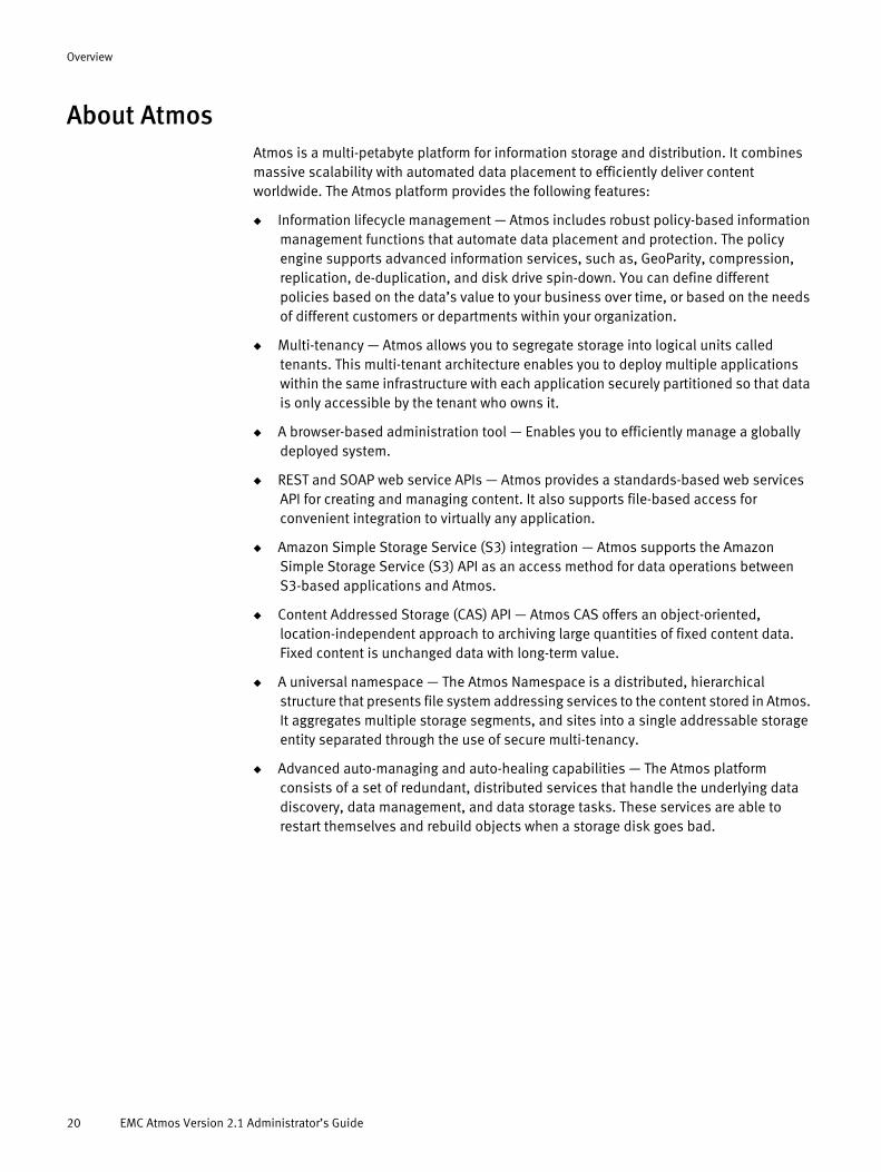
About AtmosAtmos is a multi-petabyte platform for information storage and distribution. It combines massive scalability with automated data placement to efficiently deliver content worldwide. The Atmos platform provides the following features:
◆ Information lifecycle management — Atmos includes robust policy-based information management functions that automate data placement and protection. The policy engine supports advanced information services, such as, GeoParity, compression, replication, de-duplication, and disk drive spin-down. You can define different policies based on the data’s value to your business over time, or based on the needs of different customers or departments within your organization.
◆ Multi-tenancy — Atmos allows you to segregate storage into logical units called tenants. This multi-tenant architecture enables you to deploy multiple applications within the same infrastructure with each application securely partitioned so that data is only accessible by the tenant who owns it.
◆ A browser-based administration tool — Enables you to efficiently manage a globally deployed system.
◆ REST and SOAP web service APIs — Atmos provides a standards-based web services API for creating and managing content. It also supports file-based access for convenient integration to virtually any application.
◆ Amazon Simple Storage Service (S3) integration — Atmos supports the Amazon Simple Storage Service (S3) API as an access method for data operations between S3-based applications and Atmos.
◆ Content Addressed Storage (CAS) API — Atmos CAS offers an object-oriented, location-independent approach to archiving large quantities of fixed content data. Fixed content is unchanged data with long-term value.
◆ A universal namespace — The Atmos Namespace is a distributed, hierarchical structure that presents file system addressing services to the content stored in Atmos. It aggregates multiple storage segments, and sites into a single addressable storage entity separated through the use of secure multi-tenancy.
◆ Advanced auto-managing and auto-healing capabilities — The Atmos platform consists of a set of redundant, distributed services that handle the underlying data discovery, data management, and data storage tasks. These services are able to restart themselves and rebuild objects when a storage disk goes bad.
20 EMC Atmos Version 2.1 Administrator’s Guide

Overview
Atmos architectureThe Atmos platform consists of a set of redundant, distributed services that handle the underlying data discovery, data management, and data storage tasks. The following diagram illustrates the set of Atmos services:
Figure 1 Atmos Services
Atmos architecture 21
Overview
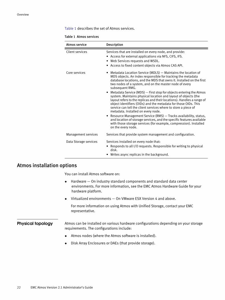
Table 1 describes the set of Atmos services.
Atmos installation options
You can install Atmos software on:
◆ Hardware — On industry standard components and standard data center environments. For more information, see the EMC Atmos Hardware Guide for your hardware platform.
◆ Virtualized environments — On VMware ESX Version 4 and above.
For more information on using Atmos with Unified Storage, contact your EMC representative.
Physical topology Atmos can be installed on various hardware configurations depending on your storage requirements. The configurations include:
◆ Atmos nodes (where the Atmos software is installed).
◆ Disk Array Enclosures or DAEs (that provide storage).
Table 1 Atmos services
Atmos service Description
Client services Services that are installed on every node, and provide: • Access for external applications via NFS, CIFS, IFS.• Web Services requests and WSDL. • Access to fixed content objects via Atmos CAS API.
Core services • Metadata Location Service (MDLS) — Maintains the location of MDS objects. An index responsible for tracking the metadata database locations, and the MDS that owns it. Installed on the first two nodes of a system, and on the master node of every subsequent RMG.
• Metadata Service (MDS) — First stop for objects entering the Atmos system. Maintains physical location and layout of objects (the layout refers to the replicas and their locations). Handles a range of object identifiers (OIDs) and the metadata for those OIDs. This service can tell the client services where to store a piece of metadata. Installed on every node.
• Resource Management Service (RMS) — Tracks availability, status, and location of storage services, and the specific features available with those storage services (for example, compression). Installed on the every node.
Management services Services that provide system management and configuration.
Data Storage services Services installed on every node that: • Responds to all I/O requests. Responsible for writing to physical
disk. • Writes async replicas in the background.
22 EMC Atmos Version 2.1 Administrator’s Guide

Overview
Figure 2 illustrates a logical representation of the two components (nodes and storage) mapped to physical hardware:
Figure 2 WS2-series hardware node to storage mapping
Figure 3 illustrates the Atmos Virtual Edition (AVE) topology. In the virtualized environment, the Atmos front-end nodes map to virtual machines.
Figure 3 Atmos Virtual Edition topology
Atmos architecture 23
Overview
Atmos front-end nodes
The front-end nodes of an Atmos system are further defined within an Atmos system as:
◆ (One or more) Installation segments — An installation segment (IS) is a set of the front-end nodes that share the same private management subnet.
• These front-end Atmos nodes run the set of services to store, retrieve, categorize, and manage the data in the system. See Table 1 for a description of the Atmos services. The set of services installed and running on a node depends on whether the node is a master or slave node.
• One node in an installation segment is the master node. This is the first node installed in each installation segment. All other nodes in the installation segment are slave nodes. You install the Atmos software on the master node, then PXE-boot the slave nodes from the master.
• One node in the entire system is the initial master node. This is the first node of the first installation segment that is installed. (You use the IP address of this node to login and manage the system using the Atmos System Administration Console.)
• On a physical Atmos system, an installation segment is attached to one or more disk array enclosures (DAE) or racks.
• Traffic between Atmos nodes cannot be blocked by a firewall.
◆ (One or more) Resource Management Groups (RMGs) — An RMG is a collection of installation segments that share a single IP multicast domain.
• In most cases, this is equivalent to a subnet on the customer’s public network.
• You can create multiple RMGs on the same subnet.
• RMGs are always associated with a location (such as Boston, Paris, 2nd Floor, Building A). This location association or tag is critical because the Atmos policy manager uses it to determine where to read from and write data to.
• You typically install and manage Atmos at the RMG level. You typically upgrade Atmos at the installation segment or location level.
• All of the RMGs installed within a system must be routable to one another. The RMGs communicate via TCP/IP.
Network topology Each Atmos installation segment has at least two Ethernet ports:
◆ eth0 — For the private management network. The private management network is automatically assigned a private IP address during installation. Atmos uses this network for internal management traffic, such as:
• Installing Atmos (PXE, DHCP, and IPMI)
• Intra-node communications (within an IS)
• Upgrading to a new Atmos version
• Replacing nodes
◆ eth1 — (eth1 and above) Assigned externally facing IP addresses. Atmos uses this network for:
24 EMC Atmos Version 2.1 Administrator’s Guide

Overview
• Tenant access and data replication traffic. The traffic initiated via the Atmos storage API, Amazon S3 applications, and the Atmos CAS API.
• System management traffic. The traffic initiated via the Atmos System Administration Console or applications written to the system management API.
Figure 4 shows the default Atmos network interface topology.
Figure 4 Atmos node network interfaces
Atmos networks can be modified in the following ways:
◆ Bonding physical interfaces.
Location 1
Resource Management Group N-1
Resource Management Group N
Location 2
Installation Segment A
eth0 Node N eth1
Resource Management Group
eth0 Node 0 eth1“public”customernetwork“private”
managementsubnet
Router
Router
...
Installation Segment B
eth0 Node N eth1
eth0 Node 0 eth1“private”managementsubnet
...
Location
Resource Management Group
eth0 Node eth1
Rack
Installation Segment
Atmos architecture 25
Overview
◆ Creating virtual interfaces on the public network (eth1) to separate data, management and tenant access traffic.
◆ Assigning VLAN tags to physical or virtual interfaces.
◆ Adding or removing static routes
Contact your EMC sales representative for more information.
Atmos and object accessAtmos stores unstructured content such as movies, Word files, graphics, and so on, as objects. Each Atmos object is comprised of the following components:
◆ Data — The user’s content such as, audio files, video files, Word documents, and images.
◆ Metadata — The object’s attributes. Every object has a set of system metadata such as, last access time, change time, create time, and object size, by default. In addition, you can define your own custom set of user metadata for each object. You can then use this rich set of metadata to automate how and where Atmos stores and retrieves the object based on a policy.
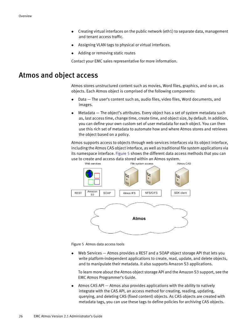
Atmos supports access to objects through web services interfaces via its object interface, including the Atmos CAS object interface, as well as traditional file system applications via its namespace interface. Figure 5 shows the different data access methods that you can use to create and access data stored within an Atmos system.
Figure 5 Atmos data access tools
◆ Web Services — Atmos provides a REST and a SOAP object storage API that lets you write platform-independent applications to create, read, update, and delete objects, and to manipulate their metadata. It also supports Amazon S3 applications.
To learn more about the Atmos object storage API and the Amazon S3 support, see the EMC Atmos Programmer’s Guide.
◆ Atmos CAS API — Atmos also provides applications with the ability to natively integrate with the CAS API, an access method for creating, reading, updating, querying, and deleting CAS (fixed content) objects. As CAS objects are created with metadata tags, you can use these tags to define policies for archiving CAS objects.
26 EMC Atmos Version 2.1 Administrator’s Guide

Overview
To learn more about the Atmos CAS API, see the EMC Atmos CAS API Reference Guide and EMC Atmos CAS Programmer’s Guide. To configure CAS, see the Atmos online help and appropriate chapters in this guide.
◆ File system access — Atmos supports access from traditional file system applications for Windows with CIFS, Linux with NFS, or Linux using the Atmos installable file system (IFS).
To learn more about CIFS and NFS access, see Chapter 11, “SubtenantAdmin Basics.”
About the Atmos Installable File System
The Atmos installable file system (IFS) allows applications to access Atmos objects through a traditional, file system interface.
If you want file system access natively for remote clients, you can install the Atmos installable file system on a server running supported versions of Linux outside the standard Atmos cluster. Figure u shows the IFS components.
Figure 6 Atmos IFS components
◆ Atmos — The Atmos system that you want to communicate with.
◆ Linux server — Linux server where you install the Atmos IFS along with either Samba or NFS to enable access to NFS or Samba clients.
For information about supported Linux platforms and versions, see the Atmos Release Notes.
Atmos system management toolsAtmos provides the following tools for managing, monitoring, and configuring your Atmos system (RMGs, installation segments, tenants, subtenants, access nodes and so on).
◆ System Administration Console — A browser-based graphical interface that lets you manage access, monitor performance and capacity, and configure tenants and subtenants. You use this tool to manage multiple Atmos servers at multiple locations.
Atmos system management tools 27
Overview
◆ System management API — A REST-based API that lets you programmatically perform a subset of the system management functions.
To learn more about the system management API, see the EMC Atmos System Management API Guide.
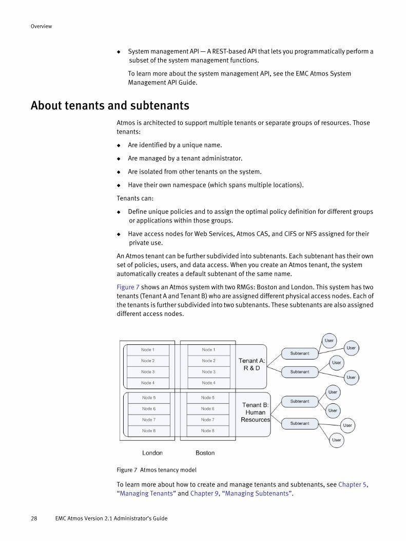
About tenants and subtenantsAtmos is architected to support multiple tenants or separate groups of resources. Those tenants:
◆ Are identified by a unique name.
◆ Are managed by a tenant administrator.
◆ Are isolated from other tenants on the system.
◆ Have their own namespace (which spans multiple locations).
Tenants can:
◆ Define unique policies and to assign the optimal policy definition for different groups or applications within those groups.
◆ Have access nodes for Web Services, Atmos CAS, and CIFS or NFS assigned for their private use.
An Atmos tenant can be further subdivided into subtenants. Each subtenant has their own set of policies, users, and data access. When you create an Atmos tenant, the system automatically creates a default subtenant of the same name.
Figure 7 shows an Atmos system with two RMGs: Boston and London. This system has two tenants (Tenant A and Tenant B) who are assigned different physical access nodes. Each of the tenants is further subdivided into two subtenants. These subtenants are also assigned different access nodes.
Figure 7 Atmos tenancy model
To learn more about how to create and manage tenants and subtenants, see Chapter 5, “Managing Tenants” and Chapter 9, “Managing Subtenants”.
28 EMC Atmos Version 2.1 Administrator’s Guide

Overview
About policyThe Atmos policy engine performs automatic data placement and transformation based on criteria you specify. The policy engine lets you define:
◆ How many replicas of an object to create.
◆ How long to retain one or more of those replicas.
◆ Where to store the replicas. (For example, you can choose to distribute content closer to where it is used.)
◆ What data services to apply to the replicas (such as deduplication, compression, and striping).
◆ How to protect the replicas (for example, by applying GeoParity).
Atmos can apply a policy based on an object’s system metadata or user metadata.
You use the system management tools to define Atmos policy. To learn more, see Chapter 10, “Managing Policies.”
About administrative rolesAtmos includes four administrative roles:
◆ “SecurityAdmin”
◆ “SysAdmin”
◆ “TenantAdmin”
◆ “SubtenantAdmin”
SecurityAdmin The SecurityAdmin is responsible for initiating an Atmos system and creating SysAdmins to manage the system. During the installation process, the SecurityAdmin:
◆ Resets the default SecurityAdmin password.
◆ Assigns users to the SysAdmin role.
An Atmos system has one SecurityAdmin.
SysAdmin The SysAdmin role is responsible for overall management of an Atmos system. Users in the SysAdmin role are responsible for:
◆ Managing installation segments, RMGs, and nodes.
◆ Changing faulty disks.
◆ Adding new hardware.
◆ Creating and managing tenants.
◆ Configuring Atmos nodes for tenant access for a particular access type (web services, file system, or CAS).
◆ Creating and managing location groups.
◆ Assigning users to the TenantAdmin role.
About policy 29

Overview
Multiple users can be assigned the SysAdmin role.
Users who are assigned the SysAdmin role can be authenticated against either the internal authentication source maintained by the Atmos system (referred to as local authentication) or an external authentication source maintained by the customer (referred to as remote authentication). To use an external authentication source, additional configuration must be completed.
TenantAdmin Users in the TenantAdmin role is responsible for:
◆ Managing subtenants.
◆ Creating policy specifications, policy selectors, and (optionally) policy transition specifications.
◆ Assigning policies to subtenants.
◆ Assigning users to the SubtenantAdmin role.
Users in the TenantAdmin role share the following tasks with SubtenantAdmins:
◆ Configuring CIFS or NFS for an assigned access node.
◆ Registering applications (which involves generating a UID/Shared Secret).
TenantAdmins are only aware of the system resources defined for their tenant. They have no ability to view or access other system resources.
A tenant can have multiple TenantAdmins, but a TenantAdmin can be a TenantAdmin for only one tenant. A TenantAdmin can perform all of the tasks that a SubtenantAdmin can.
SubtenantAdmin Subtenants are logical partitions of tenants that group together selected policies, data access, and reporting capabilities. Each subtenant has a unique set of users and sees a unique set of data. A given object can be seen by only one subtenant.
When the SysAdmin creates a tenant, the system automatically creates one corresponding subtenant (which is identical to the tenant).
TenantAdmins can create additional subtenants within their tenant. Users in the SubtenantAdmin role are responsible for:
◆ Creating, generate, disable a UID.
◆ Configuring CIFS or NFS access on specific access nodes.
Authentication of administrative roles
Authentication may depend on the internal authentication source maintained by the Atmos system (referred to as local authentication) or an external authentication source maintained by the customer. (referred to as remote authentication).
The authentication service comprises multiple authentication servers (one master and several read-only slaves). If the master authentication server is temporarily unavailable (for example, because it is down or there is a network disconnection), a failover process is triggered. This occurs only rarely. Complete failover takes some time (roughly 15 minutes, depending on the size and configuration of your system). While failover is in progress,
30 EMC Atmos Version 2.1 Administrator’s Guide
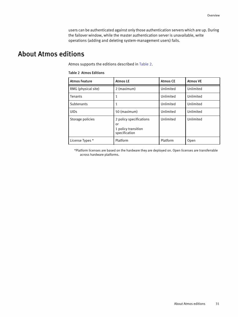
Overview
users can be authenticated against only those authentication servers which are up. During the failover window, while the master authentication server is unavailable, write operations (adding and deleting system-management users) fails.
About Atmos editionsAtmos supports the editions described in Table 2.
*Platform licenses are based on the hardware they are deployed on. Open licenses are transferrable across hardware platforms.
Table 2 Atmos Editions
Atmos Feature Atmos LE Atmos CE Atmos VE
RMG (physical site) 2 (maximum) Unlimited Unlimited
Tenants 1 Unlimited Unlimited
Subtenants 1 Unlimited Unlimited
UIDs 50 (maximum) Unlimited Unlimited
Storage policies 2 policy specifications or1 policy transition specification
Unlimited Unlimited
License Types * Platform Platform Open
About Atmos editions 31

Overview
32 EMC Atmos Version 2.1 Administrator’s Guide
CHAPTER 2SecurityAdmin Basics
This chapter includes the following sections:
◆ Overview................................................................................................................. 34◆ Logging in ............................................................................................................... 34◆ Adding users to the SysAdmin role.......................................................................... 35◆ Removing a SysAdmin............................................................................................. 40◆ Modifying SecurityAdmin information ..................................................................... 40
SecurityAdmin Basics 33

SecurityAdmin Basics
OverviewThe SecurityAdmin is responsible for initiating an Atmos system and for adding users to the SysAdmin role. During the installation process, the SecurityAdmin:
◆ Resets the SecurityAdmin password.
◆ Assigns users to the SysAdmin role.
◆ Configures remote LDAP servers if users in the SysAdmin role are to be authenticated via remote servers.
Any LDAP servers that are configured are also available for authentication by users in the TenantAdmin and SubtenantAdmin roles.
An Atmos system has one SecurityAdmin. The SecurityAdmin is authenticated by the Atmos system (local authentication).
Note: The Atmos administration console does not support Unicode input.
Logging in 1. To log in as the SecurityAdmin, enter the URL:
https://hostname/mgmt_login
Note: If you already are logged in as a TenantAdmin or SubtenantAdmin, log out, then click the Log in TenantAdmin/SubtenantAdmin link.
2. Enter the following fields.
When Auth Type is local, then login credentials are not case-sensitive.
◆ Auth Type — Select Local.
◆ User Name — Enter SecurityAdmin.
◆ Password — Enter the SecurityAdmin password.
34 EMC Atmos Version 2.1 Administrator’s Guide

SecurityAdmin Basics
3. Click Login.
Adding users to the SysAdmin roleUsers assigned to the SysAdmin role can be authenticated against either the internal authentication source maintained by the Atmos system (called local authentication) or an external authentication source maintained by the customer (called remote authentication).
Only LDAP is supported as a remote authentication mechanism for administrators. You can use LDAP to connect to Microsoft Active Directory (AD) as the authentication service provider.
Use remote authentication when your site requires external, centralized authentication. If you use remote authentication, you need to complete an extra configuration page so that Atmos can connect to the remote source. Once configured, the remote source can be used to authenticate users assigned to the SysAdmin, TenantAdmin, and SubTenantAdmin roles.
Note: If you use remote authentication, Atmos recommends that you also configure at least one SysAdmin account for local authentication so that if the remote authentication server becomes unreachable, you can still use the locally authenticated account to log in.
To perform the configuration, you need to work with the LDAP or Microsoft Active Directory administrator to gather details about the LDAP server. See “Configuring an LDAP server as a remote authentication source” on page 37 for details on the required configuration information.
Follow the appropriate procedure to create a new SysAdmin:
◆ “Using local authentication”
◆ “Using remote authentication” (if the remote authentication source has already been configured).
For instructions on how to configure a remote authentication source, see “Configuring an LDAP server as a remote authentication source” on page 37.
Atmos SysAdmin naming rules
The SysAdmin name can include up to 255 alphanumeric characters and the following symbols:
underscore (_) @
dollar sign ($) caret (^)
comma (,) parentheses ()
braces ([ ]) brackets ({ })
Adding users to the SysAdmin role 35
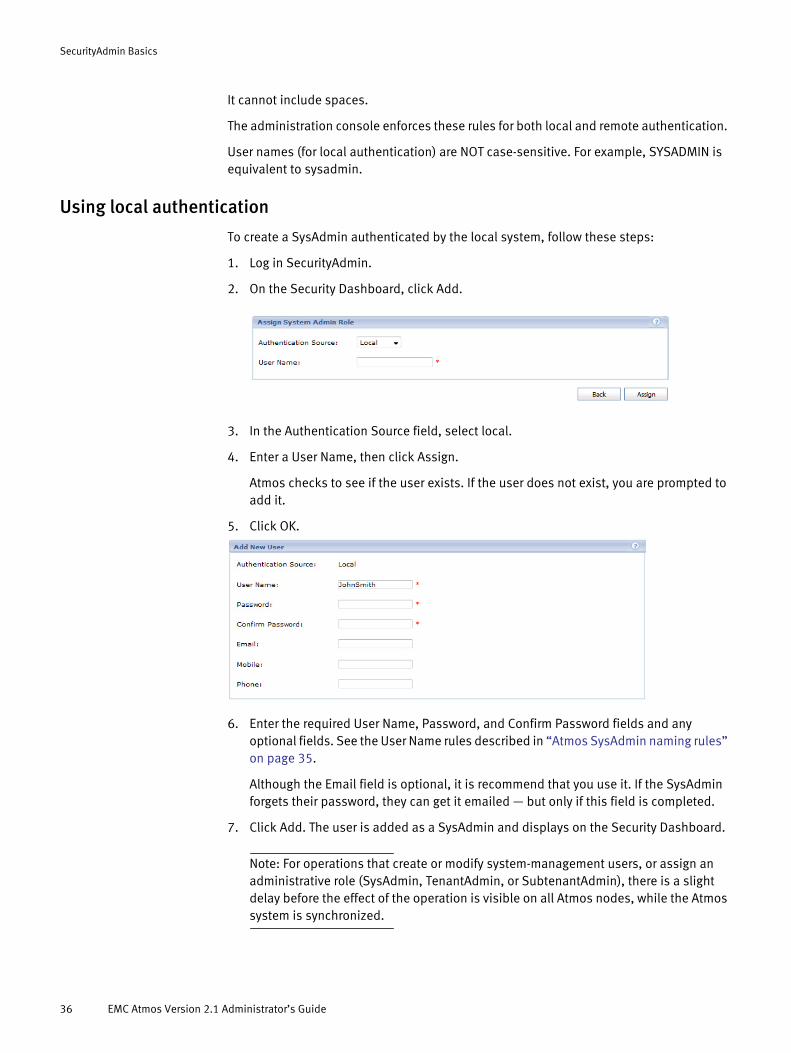
SecurityAdmin Basics
It cannot include spaces.
The administration console enforces these rules for both local and remote authentication.
User names (for local authentication) are NOT case-sensitive. For example, SYSADMIN is equivalent to sysadmin.
Using local authentication
To create a SysAdmin authenticated by the local system, follow these steps:
1. Log in SecurityAdmin.
2. On the Security Dashboard, click Add.
3. In the Authentication Source field, select local.
4. Enter a User Name, then click Assign.
Atmos checks to see if the user exists. If the user does not exist, you are prompted to add it.
5. Click OK.
6. Enter the required User Name, Password, and Confirm Password fields and any optional fields. See the User Name rules described in “Atmos SysAdmin naming rules” on page 35.
Although the Email field is optional, it is recommend that you use it. If the SysAdmin forgets their password, they can get it emailed — but only if this field is completed.
7. Click Add. The user is added as a SysAdmin and displays on the Security Dashboard.
Note: For operations that create or modify system-management users, or assign an administrative role (SysAdmin, TenantAdmin, or SubtenantAdmin), there is a slight delay before the effect of the operation is visible on all Atmos nodes, while the Atmos system is synchronized.
36 EMC Atmos Version 2.1 Administrator’s Guide
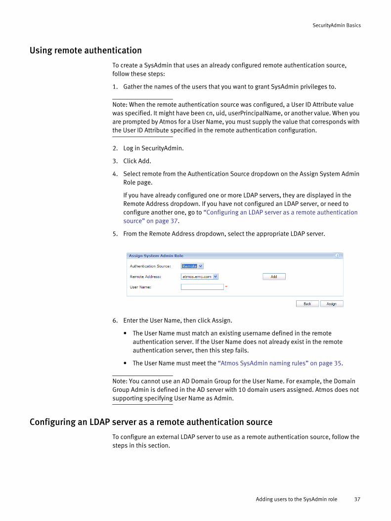
SecurityAdmin Basics
Using remote authentication
To create a SysAdmin that uses an already configured remote authentication source, follow these steps:
1. Gather the names of the users that you want to grant SysAdmin privileges to.
Note: When the remote authentication source was configured, a User ID Attribute value was specified. It might have been cn, uid, userPrincipalName, or another value. When you are prompted by Atmos for a User Name, you must supply the value that corresponds with the User ID Attribute specified in the remote authentication configuration.
2. Log in SecurityAdmin.
3. Click Add.
4. Select remote from the Authentication Source dropdown on the Assign System Admin Role page.
If you have already configured one or more LDAP servers, they are displayed in the Remote Address dropdown. If you have not configured an LDAP server, or need to configure another one, go to “Configuring an LDAP server as a remote authentication source” on page 37.
5. From the Remote Address dropdown, select the appropriate LDAP server.
6. Enter the User Name, then click Assign.
• The User Name must match an existing username defined in the remote authentication server. If the User Name does not already exist in the remote authentication server, then this step fails.
• The User Name must meet the “Atmos SysAdmin naming rules” on page 35.
Note: You cannot use an AD Domain Group for the User Name. For example, the Domain Group Admin is defined in the AD server with 10 domain users assigned. Atmos does not supporting specifying User Name as Admin.
Configuring an LDAP server as a remote authentication source
To configure an external LDAP server to use as a remote authentication source, follow the steps in this section.
Adding users to the SysAdmin role 37

SecurityAdmin Basics
1. Work with the administrator of the LDAP or AD server to gather the configuration information in the following table.
Atmos Prompt Description Examples
Auth Name An alphanumeric string — Use this field to label a particular LDAP or AD server within the Atmos environment. This is especially useful when multiple remote servers are used within an Atmos system. For AD, it is useful to choose the Domain name
ASD-CSE
or atmos.emc.com
Bind DN The Distinguished Name to use to connect to the LDAP server. For AD, there is no requirement to give BindDN account admin privileges, but at a minimum, the Bind DN account must have:• Read access to the user objects in the LDAP
directory in order to search for user accounts• Read access to the Base DN (for example,
DC=angsupport, DC=com) with the correct attribute that is used as the LDAP Login Name (for example, samAccountName)
• For Group Extraction, which is the process of determining a user’s group membership and returning those values to Access Gateway Enterprise Edition, the Bind DN account must also have read access to the group attributes in the LDAP directory
cn=root,dc=host,dc=example,dc=com
or cn=Administrator,cn=Users,dc=ASD-CE,dc=TST
or cn=admin,ou=atmos,dc=emc,dc=com
Bind password Password for Bind DN. For AD this is the password for the user that is being used to join the AD server itself.
ChangeMe
Server Name LDAP server locations or IP addresses, separated by spaces.For AD, this is the fully qualified domain name or IP address of the AD Server itself.
AD-Master.ASD-CSE.TST
or 10.245.33.133
LDAP Debug Level Debug level for the server.Setting it to zero prevents clear text passwords.
0
Protocol LDAP
Note: LDAPS and TLS are not supported.
LDAP
Port Number Specify 389 for LDAP. 389
LDAP Timeout Timeout interval (in milliseconds) to use when communicating with the LDAP server.0 = none and max = 2bn
30000
User Search path Distinguished Name (DN) where to begin User searches
cn=Users,dc=ASD-CSE,dc=TST
or ou=People,ou=atmos,dc=emc,dc=com
Group Search Path Distinguished Name (DN) where to begin Group searches
cn=Users,dc=ASD-CSE,dc=TST
or ou=Group,ou=atmos,dc=emc,dc=com
User Object Class Object class identifying users in the LDAP hierarchy
User
orposixAccount
38 EMC Atmos Version 2.1 Administrator’s Guide
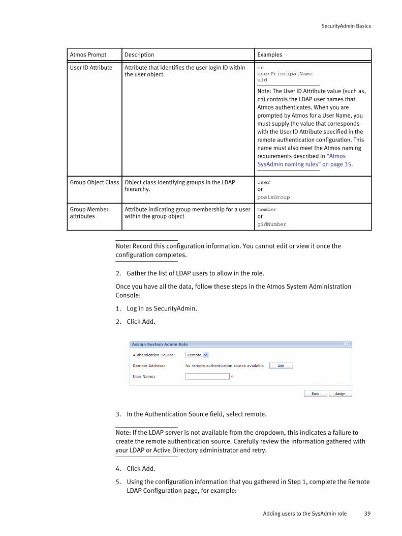
SecurityAdmin Basics
Note: Record this configuration information. You cannot edit or view it once the configuration completes.
2. Gather the list of LDAP users to allow in the role.
Once you have all the data, follow these steps in the Atmos System Administration Console:
1. Log in as SecurityAdmin.
2. Click Add.
3. In the Authentication Source field, select remote.
Note: If the LDAP server is not available from the dropdown, this indicates a failure to create the remote authentication source. Carefully review the information gathered with your LDAP or Active Directory administrator and retry.
4. Click Add.
5. Using the configuration information that you gathered in Step 1, complete the Remote LDAP Configuration page, for example:
User ID Attribute Attribute that identifies the user login ID within the user object.
cnuserPrincipalNameuid
Note: The User ID Attribute value (such as, cn) controls the LDAP user names that Atmos authenticates. When you are prompted by Atmos for a User Name, you must supply the value that corresponds with the User ID Attribute specified in the remote authentication configuration. This name must also meet the Atmos naming requirements described in “Atmos SysAdmin naming rules” on page 35.
Group Object Class Object class identifying groups in the LDAP hierarchy.
User
or posixGroup
Group Member attributes
Attribute indicating group membership for a user within the group object
member
or gidNumber
Atmos Prompt Description Examples
Adding users to the SysAdmin role 39

SecurityAdmin Basics
6. Click Save to return to the Assign System Admin Role page.
7. To refresh the list of remote LDAP servers, select local then select remote from the Authentication Source dropdown.
8. Select the LDAP server from the Remote Address dropdown.
(The value you entered in the Auth Name field is displayed in this dropdown.)
9. Enter the User Name, then click Assign.
Removing a SysAdminTo delete a SysAdmin, follow these steps:
1. Log in as SecurityAdmin.
2. In the row for the SysAdmin you want to remove, click Remove Role.
3. In the pop-up dialog asking you to confirm, click OK.
Note: This action does not delete the user from either the remote or local authentication source, it simply removes that user from the SysAdmin role.
Modifying SecurityAdmin informationTo view or modify SecurityAdmin information:
40 EMC Atmos Version 2.1 Administrator’s Guide
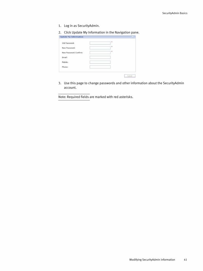
SecurityAdmin Basics
1. Log in as SecurityAdmin.
2. Click Update My Information in the Navigation pane.
3. Use this page to change passwords and other information about the SecurityAdmin account.
Note: Required fields are marked with red asterisks.
Modifying SecurityAdmin information 41

SecurityAdmin Basics
42 EMC Atmos Version 2.1 Administrator’s Guide
PART 1
SysAdmin
This part includes the following chapters:
Chapter 3, “SysAdmin Basics.”
This chapter introduces the SysAdmin role and the tools available to SysAdmin users.
Chapter 4, “Configuring the Atmos System.”
This chapter describes how to access and configure Atmos system settings.
Chapter 5, “Managing Tenants.”
This chapter describes how to manage tenants using the System Dashboard.
Chapter 6, “System Monitoring, Events, & Reporting.”
This chapter describes how to configure and use Atmos system monitoring (the operational reporting framework), event notifications, system reporting, and log collection.
Chapter 7, “Getting Performance Data.”
This chapter explains how to obtain performance data from any workstation that can access an Atmos server.

CHAPTER 3SysAdmin Basics
Introduces the SysAdmin role and the tools available to users in the role. It includes the following topics:
◆ Overview................................................................................................................. 46◆ Logging in ............................................................................................................... 46◆ Using the SysAdmin dashboard .............................................................................. 47◆ Working with RMGs and nodes................................................................................ 52◆ Modifying SysAdmin information ............................................................................ 59◆ Replacing failed disks ............................................................................................. 60
SysAdmin Basics 45

SysAdmin Basics
OverviewUsers in the SysAdmin role are responsible for overall management of an Atmos system. They are responsible for:
◆ Managing installation segments, RMGs, and nodes.
◆ Creating and managing tenants, and assigning users to the TenantAdmin role.
◆ Configuring specific nodes for tenant access, and defining the access type (web services, file system, or CAS).
◆ Creating and managing location groups.
Note: Configuration changes made using the administration console can take up to ten minutes to propagate across the system. When Atmos has trouble accessing particular nodes, changes will take affect on these nodes ten minutes after access has been restored.
Note: The Atmos administration console does not support Unicode input.
Logging in1. To log in as the SysAdmin, enter the URL:
https://hostname/mgmt_login
Note: If you already are logged in as a TenantAdmin or SubtenantAdmin, log out, then click the Switch to SystemAdmin login page link on the TenantAdmin/SubtenantAdmin login page.
Figure 8
2. Enter the following fields.
◆ Auth Type — Select Local
◆ User Name — Enter the SysAdmin name.
◆ Password — Enter the SysAdmin password.
46 EMC Atmos Version 2.1 Administrator’s Guide
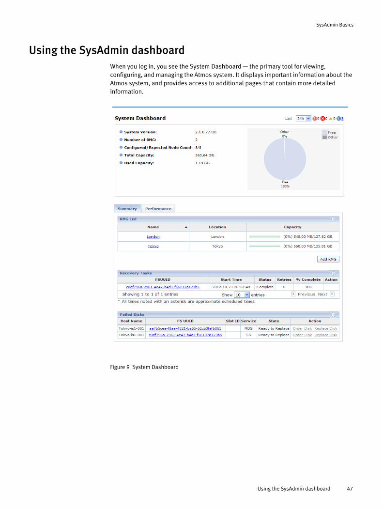
SysAdmin Basics
Using the SysAdmin dashboardWhen you log in, you see the System Dashboard — the primary tool for viewing, configuring, and managing the Atmos system. It displays important information about the Atmos system, and provides access to additional pages that contain more detailed information.
Figure 9 System Dashboard
Using the SysAdmin dashboard 47

SysAdmin Basics
It includes:
◆ Event summary — View the event type counts for a selected time period. Click the link for each event type to view node-level details.
◆ System Version — The Atmos version and build the system is currently running.
◆ Number of RMG — The number of RMGs currently configured.
◆ Configured/Expected Node Count — The total number of nodes currently configured/The number of nodes defined at installation.
◆ Total/Used Capacity — The system’s storage service capacity. This capacity is aggregated and updated periodically.
About the Summary tab
The Summary tab provides access to the following:
◆ “RMG List”
◆ “Recovery Tasks List”
◆ “Failed Disks”
RMG ListUse this list to view details about the RMGs in your system, and to access pages to view and manage the nodes within the RMG. To learn more about managing RMGs and nodes, see “Working with RMGs and nodes” on page 52.
Figure 10 Sample RMG list
Table 3 Event summary icons
Icon Description
Critical condition. Click to see messages about conditions that require immediate attention.
Error. Click to see messages about error conditions. These messages are typically reporting either a physical failure (for example, a disk has failed), or a software failure (for example, unable to distribute a policy).
Warning. Click to see status messages about less than optimal conditions (for example, a disk is starting to fill up).
Information. Click to see routine status messages or the status of an event that has not returned to a normal state.
48 EMC Atmos Version 2.1 Administrator’s Guide
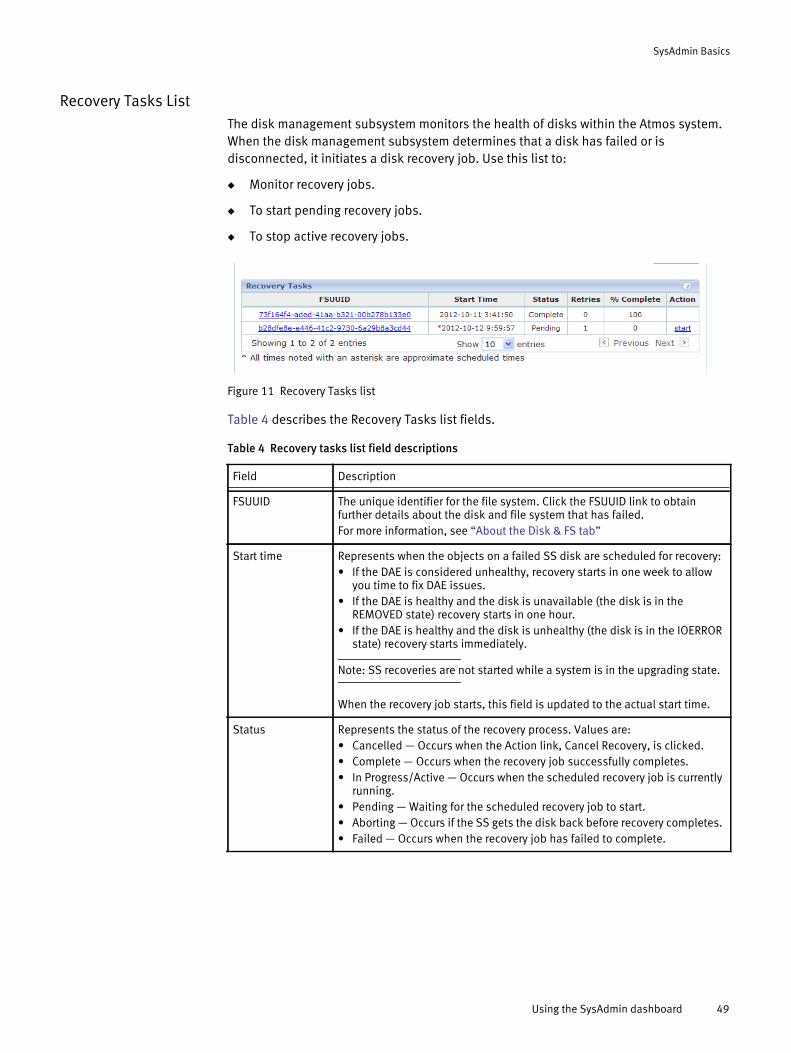
SysAdmin Basics
Recovery Tasks ListThe disk management subsystem monitors the health of disks within the Atmos system. When the disk management subsystem determines that a disk has failed or is disconnected, it initiates a disk recovery job. Use this list to:
◆ Monitor recovery jobs.
◆ To start pending recovery jobs.
◆ To stop active recovery jobs.
Figure 11 Recovery Tasks list
Table 4 describes the Recovery Tasks list fields.
Table 4 Recovery tasks list field descriptions
Field Description
FSUUID The unique identifier for the file system. Click the FSUUID link to obtain further details about the disk and file system that has failed. For more information, see “About the Disk & FS tab”
Start time Represents when the objects on a failed SS disk are scheduled for recovery:• If the DAE is considered unhealthy, recovery starts in one week to allow
you time to fix DAE issues. • If the DAE is healthy and the disk is unavailable (the disk is in the
REMOVED state) recovery starts in one hour.• If the DAE is healthy and the disk is unhealthy (the disk is in the IOERROR
state) recovery starts immediately.
Note: SS recoveries are not started while a system is in the upgrading state.
When the recovery job starts, this field is updated to the actual start time.
Status Represents the status of the recovery process. Values are: • Cancelled — Occurs when the Action link, Cancel Recovery, is clicked. • Complete — Occurs when the recovery job successfully completes. • In Progress/Active — Occurs when the scheduled recovery job is currently
running. • Pending — Waiting for the scheduled recovery job to start. • Aborting — Occurs if the SS gets the disk back before recovery completes. • Failed — Occurs when the recovery job has failed to complete.
Using the SysAdmin dashboard 49
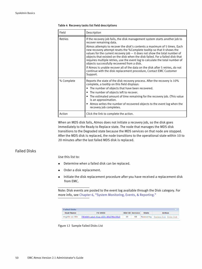
SysAdmin Basics
When an MDS disk fails, Atmos does not initiate a recovery job, so the disk goes immediately to the Ready to Replace state. The node that manages the MDS disk transitions to the Degraded state because the MDS services on that node are stopped. After the MDS disk is replaced, the node transitions to the operational state within 10 to 20 minutes after the last failed MDS disk is replaced.
Failed DisksUse this list to:
◆ Determine when a failed disk can be replaced.
◆ Order a disk replacement.
◆ Initiate the disk replacement procedure after you have received a replacement disk from EMC.
Note: Disk events are posted to the event log available through the Disk category. For more info, see Chapter 6, “System Monitoring, Events, & Reporting.”
Figure 12 Sample Failed Disks List
Retries If the recovery job fails, the disk management system starts another job to recover remaining data. Atmos attempts to recover the disk’s contents a maximum of 5 times. Each new recovery attempt resets the %Complete tooltip so that it shows the values for the current recovery job — it does not show the total number of objects that existed on the disk when the disk failed. For a failed disk that requires multiple retries, use the event log to calculate the total number of objects successfully recovered from a disk.If Atmos is unable recover all of the data on the disk after 5 retries, do not continue with the disk replacement procedure, Contact EMC Customer Support.
% Complete Reports the state of the disk recovery process. After the recovery is 10% complete, a tooltip on this field displays:• The number of objects that have been recovered.• The number of objects left to recover.• The estimated amount of time remaining for the recovery job. (This value
is an approximation.• Atmos writes the number of recovered objects to the event log when the
recovery job completes.
Action Click the link to complete the action.
Table 4 Recovery tasks list field descriptions
Field Description
50 EMC Atmos Version 2.1 Administrator’s Guide

SysAdmin Basics
Table 5 describes the failed disks fields.
Once a disk has been replaced, it is removed from this list and placed on the Show Removed disks page (System Only > Show Removed Disks) for historical information.
You can start the disk replacement procedure when all of the following are true:
◆ Recovery is 100% complete.
◆ The disk is in the Ready to Replace state.
◆ You have a replacement disk on hand.
The replacement disk must match the disk you intend to replace. (For more information, see “Ordering a disk” on page 60.)
About the Performance tab
The performance tab includes graphs that report performance and resource usage over specified time periods. Use the History dropdown at the top of the page to change the reporting period.
You can use the data in these graphs to understand how your business uses capacity over time and to forecast future capacity needs.
Table 5 Failed disk field descriptions
Field Description
Host Name The name of the node that owns the failed disk.
FS UUID The unique identifier for the file system. Click the FSUUID link to obtain further details about the disk and file system that has failed. For more information, see “About the Disk & FS tab” on page 58.
Slot ID The Slot within the DAE where the failed disk resides.
Service The Atmos services assigned to the failed disk. Values are: • SS — Storage service disk. Used to store objects.• MDS — Metadata service disk. Used to store metadata databases. To replace an SS or MDS disk, follow the steps described in “Replacing failed disks” on page 60.
State Displays Ready to Replace when disk recovery is complete.
Action Replace Disk — Click this link to initiate a disk replacement. This is only enabled once the State is Ready to Replace.Order Disk — Click this link to get information about how to order a replacement disk, or to place an online order.
Using the SysAdmin dashboard 51
SysAdmin Basics
Working with RMGs and nodesAn RMG is a collection of installation segments that share a single domain and location identifier. Each RMG has a master node which is the first node installed in each installation segment, and it always has -001 appended to its node name.
When you add a new RMG to an existing Atmos system, it has one installation segment and one master node. If you add more installation segments to that RMG later, there are more master nodes: an RMG with N installation segments has N master nodes.
The initial master node is the first node installed in the first installation segment in the first RMG in the system (during system installation). This is the node where the SysAdmin must login.
Use the RMG page to view important information about the RMG and the nodes that comprise it. It also provides access to additional pages that contain more detailed information.
To access the RMG summary page:
1. Log in to the System Administration Console.
The System Summary page of the System Dashboard appears. The RMG List provides links to all RMGs in this Atmos system, the location, and the used and available capacity.
2. Locate the RMG List on the Summary tab of the System Summary page, then click the name of the RMG.
52 EMC Atmos Version 2.1 Administrator’s Guide
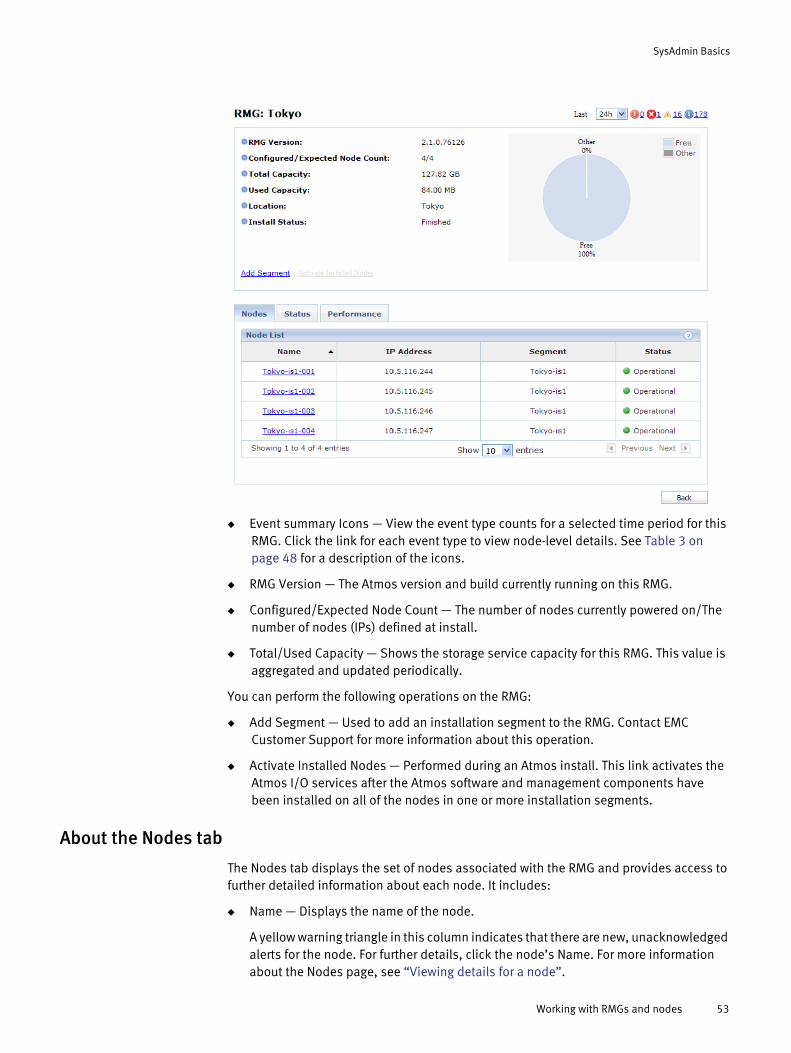
SysAdmin Basics
◆ Event summary Icons — View the event type counts for a selected time period for this RMG. Click the link for each event type to view node-level details. See Table 3 on page 48 for a description of the icons.
◆ RMG Version — The Atmos version and build currently running on this RMG.
◆ Configured/Expected Node Count — The number of nodes currently powered on/The number of nodes (IPs) defined at install.
◆ Total/Used Capacity — Shows the storage service capacity for this RMG. This value is aggregated and updated periodically.
You can perform the following operations on the RMG:
◆ Add Segment — Used to add an installation segment to the RMG. Contact EMC Customer Support for more information about this operation.
◆ Activate Installed Nodes — Performed during an Atmos install. This link activates the Atmos I/O services after the Atmos software and management components have been installed on all of the nodes in one or more installation segments.
About the Nodes tab
The Nodes tab displays the set of nodes associated with the RMG and provides access to further detailed information about each node. It includes:
◆ Name — Displays the name of the node.
A yellow warning triangle in this column indicates that there are new, unacknowledged alerts for the node. For further details, click the node’s Name. For more information about the Nodes page, see “Viewing details for a node”.
Working with RMGs and nodes 53

SysAdmin Basics
◆ IP Address — Displays the node’s IP address for the management network.
◆ Segment — Displays the name of the installation segment that contains the node.
◆ Status — Displays the node’s current status. Table Table 6 describes the possible values.
Note: Service status does not indicate the status of any disks in the RMG.
When a node’s status is not operational (for example, it is degraded), review the event log for information about that node. It typically means a service is down. If it is a critical service (such as MDS), Atmos sends an alert to EMC (if it is configured). If it is a non-critical services, contact EMC Customer Support to have the service restarted.
Table 6 Node States
Icon/Color Status values Description
(Green) Operational The node is fully functional.
(Yellow) New The node has been discovered, but installation has not started.
Replaceable The node can be replaced.
Installed The node has completed Phase 1 of the installation process.
Note: It is not yet operational.
(Red) Disconnected A node cannot be reached through the network.
Maintenance The node is in maintenance mode. Data services are not available in maintenance mode. Nodes are purposefully set to maintenance mode when certain activities (such as bonding network interfaces) are performed on the node.
Degraded Not all Atmos services are running. Nodes typically move from Operational to Degraded if a service unexpectedly stops.
Install failed The node failed to install.
Upgrade failed The node failed to upgrade.
Powered off The node is powered off.
(Blue) Installing A node enters this state when the Atmos software starts installing on the node. Once Atmos is installed on the node, the node moves to the Installed state.
Upgrading The node is upgrading or applying HotFix or Service Pack.
Synchronizing A node in the synchronizing state is verifying and synchronizing its management configuration. The node is also validating that it has the proper software updates. If a node does not have the currently installed software or service pack, it remains in the synchronizing state.
54 EMC Atmos Version 2.1 Administrator’s Guide
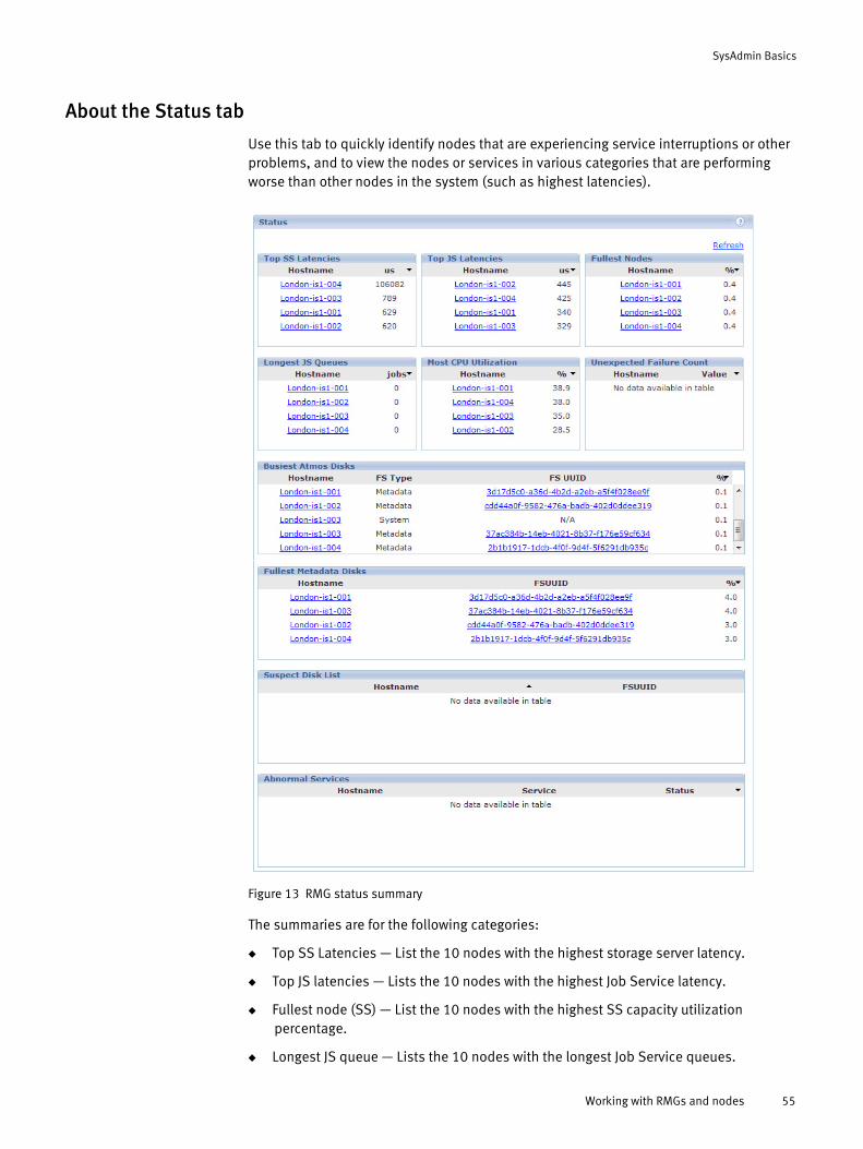
SysAdmin Basics
About the Status tab
Use this tab to quickly identify nodes that are experiencing service interruptions or other problems, and to view the nodes or services in various categories that are performing worse than other nodes in the system (such as highest latencies).
Figure 13 RMG status summary
The summaries are for the following categories:
◆ Top SS Latencies — List the 10 nodes with the highest storage server latency.
◆ Top JS latencies — Lists the 10 nodes with the highest Job Service latency.
◆ Fullest node (SS) — List the 10 nodes with the highest SS capacity utilization percentage.
◆ Longest JS queue — Lists the 10 nodes with the longest Job Service queues.
Working with RMGs and nodes 55
SysAdmin Basics
◆ Most CPU utilization — Lists the 10 nodes with the highest CPU system utilization.
◆ Unexpected Failures count — Lists the 10 nodes with the highest number of core files in the last seven days. A large number of core files (double digits) should trigger an examination of the node's operations. Triple digit counts indicate a need for intervention and correction.
◆ Busiest Atmos disks — Lists the 10 busiest disks.
◆ Fullest Metadata disks — Lists the 10 MDS disks with highest capacity utilization percentage. Atmos will send an alert when the MDS disks are nearing capacity, however it can also be useful to monitor this list.
◆ Suspect disk list — Lists the 10 disks with the highest failure prediction rate. To proactively replace any disks that appear on this list, contact EMC Technical Support.
◆ Abnormal Services — If a service is down, shows the host name, service name (and port, if applicable) and its status. The following services are monitored: CC, MDS, JS, RMS, Authserv, SSproxy, CAS, and MDLS.
Atmos refreshes each list automatically every 5 minutes. Optionally, you can refresh it manually by clicking Refresh. The internal service that collects and aggregates the data refreshes once every minute; it gathers only the data that has changed. Therefore, for different metrics, the frequency of refresh will vary, depending on the collection frequency of the metric.
Note: This page is not intended to provide a history of the state of the RMG.
About the Performance tab
Performance tab includes graphs that report performance and resource usage over specified time periods. Use the History dropdown at the top of the page to change the reporting period.
You can use the data in these graphs to understand how your business uses capacity over time and to forecast future capacity needs.
Viewing details for a node
1. Log in as SysAdmin.
2. In the RMG List area, click Detail for a given RMG. The RMG Summary page for that RMG appears.
3. From the Node List area, click the link for the node you want to view in detail. The node dashboard appears.
56 EMC Atmos Version 2.1 Administrator’s Guide
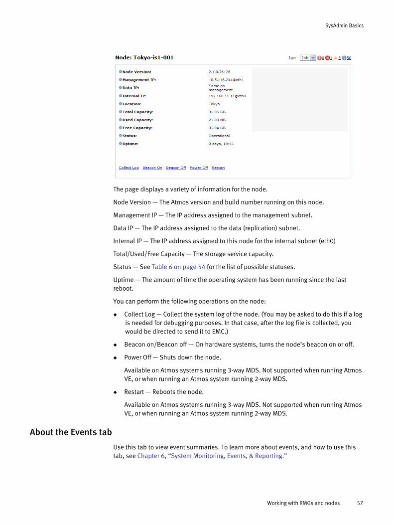
SysAdmin Basics
The page displays a variety of information for the node.
Node Version — The Atmos version and build number running on this node.
Management IP — The IP address assigned to the management subnet.
Data IP — The IP address assigned to the data (replication) subnet.
Internal IP — The IP address assigned to this node for the internal subnet (eth0)
Total/Used/Free Capacity — The storage service capacity.
Status — See Table 6 on page 54 for the list of possible statuses.
Uptime — The amount of time the operating system has been running since the last reboot.
You can perform the following operations on the node:
◆ Collect Log — Collect the system log of the node. (You may be asked to do this if a log is needed for debugging purposes. In that case, after the log file is collected, you would be directed to send it to EMC.)
◆ Beacon on/Beacon off — On hardware systems, turns the node’s beacon on or off.
◆ Power Off — Shuts down the node.
Available on Atmos systems running 3-way MDS. Not supported when running Atmos VE, or when running an Atmos system running 2-way MDS.
◆ Restart — Reboots the node.
Available on Atmos systems running 3-way MDS. Not supported when running Atmos VE, or when running an Atmos system running 2-way MDS.
About the Events tab
Use this tab to view event summaries. To learn more about events, and how to use this tab, see Chapter 6, “System Monitoring, Events, & Reporting.”
Working with RMGs and nodes 57
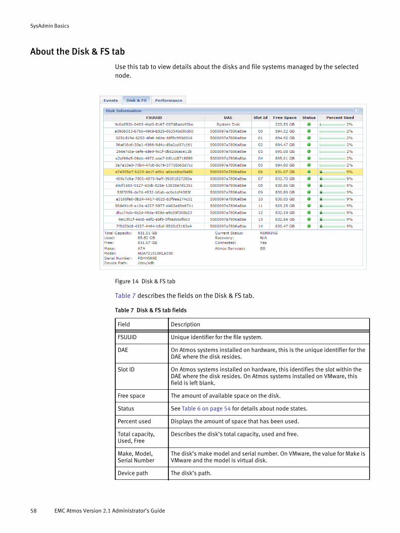
SysAdmin Basics
About the Disk & FS tab
Use this tab to view details about the disks and file systems managed by the selected node.
Figure 14 Disk & FS tab
Table 7 describes the fields on the Disk & FS tab.
Table 7 Disk & FS tab fields
Field Description
FSUUID Unique identifier for the file system.
DAE On Atmos systems installed on hardware, this is the unique identifier for the DAE where the disk resides.
Slot ID On Atmos systems installed on hardware, this identifies the slot within the DAE where the disk resides. On Atmos systems installed on VMware, this field is left blank.
Free space The amount of available space on the disk.
Status See Table 6 on page 54 for details about node states.
Percent used Displays the amount of space that has been used.
Total capacity, Used, Free
Describes the disk’s total capacity, used and free.
Make, Model, Serial Number
The disk’s make model and serial number. On VMware, the value for Make is VMware and the model is virtual disk.
Device path The disk’s path.
58 EMC Atmos Version 2.1 Administrator’s Guide
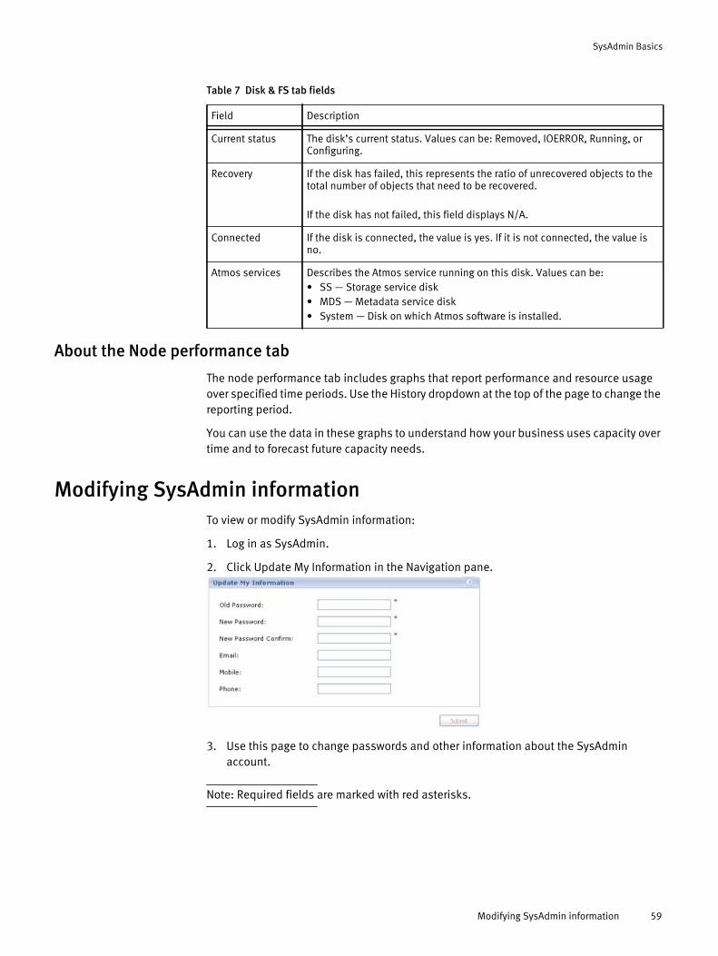
SysAdmin Basics
About the Node performance tab
The node performance tab includes graphs that report performance and resource usage over specified time periods. Use the History dropdown at the top of the page to change the reporting period.
You can use the data in these graphs to understand how your business uses capacity over time and to forecast future capacity needs.
Modifying SysAdmin informationTo view or modify SysAdmin information:
1. Log in as SysAdmin.
2. Click Update My Information in the Navigation pane.
3. Use this page to change passwords and other information about the SysAdmin account.
Note: Required fields are marked with red asterisks.
Current status The disk’s current status. Values can be: Removed, IOERROR, Running, or Configuring.
Recovery If the disk has failed, this represents the ratio of unrecovered objects to the total number of objects that need to be recovered.
If the disk has not failed, this field displays N/A.
Connected If the disk is connected, the value is yes. If it is not connected, the value is no.
Atmos services Describes the Atmos service running on this disk. Values can be: • SS — Storage service disk• MDS — Metadata service disk• System — Disk on which Atmos software is installed.
Table 7 Disk & FS tab fields
Field Description
Modifying SysAdmin information 59

SysAdmin Basics
Replacing failed disksYou can replace a disk using the disk replacement procedure in this section when the following are true:
◆ Recovery is 100% complete (see the Recovery Tasks list on the System Summary page).
◆ The disk is in the Ready to Replace state (See the Failed Disks list on the System Summary page).
◆ You have a replacement disk on hand.
◆ You are replacing a disk on a WS2 or G3 series hardware system. Do not use this procedure if you are running Atmos VE.
Follow these rules when replacing a failed disk:
◆ If there are multiple failed disks in a system, replace them one by one, repeating this procedure as needed until all drives are replaced. If both an MDS and SS disk fail, you do not have to replace the MDS disk first, but Atmos configures the first disk you insert as an MDS disk (if needed).
◆ Do not use a failed or used disk — Atmos does not accept a used or failed disk as the replacement disk.
Ordering a disk
Once a disk is recovered, the Order Disk link is enabled. Follow the link to:
◆ Find out the disk model number and size of the disk to order.
Note: Atmos requires that you replace a disk with another of the same type/model.
◆ Order a disk online.
◆ Contact the Global Customer Support centers to order the disk.
When you click the link, the following dialog displays:
Figure 15 Order disk dialog
60 EMC Atmos Version 2.1 Administrator’s Guide
SysAdmin Basics
Before placing your order, make sure you have the following information available:
◆ Site Number
◆ System Serial Number — This value corresponds to the System Master Serial Number available through the Atmos System Administration Console.
◆ Defective Part Number — This value corresponds to an EMC CRU Part Number shown in Table 8 or Table 9. Use the value in the Model field of the Order Disk dialog to locate the corresponding EMC CRU Part Number.
◆ Defective Part Serial Number — This value corresponds to the Serial # on the Order Disk dialog shown in Figure 15.
◆ Shipping information, including:
• Contact Name
• Address
• City, State, Country, Postal Code
Returning the failed disk
Follow the online instructions to return the failed part to EMC:
https://support.emc.com/servicecenter/returnPart/
Precautions
This section describes the precautions and general procedures you must follow when removing, installing, and storing any replaceable unit (CRU).
Table 8 WS2-Series replacement disk part numbers
Model EMC CRU Part Number
WD1003FBYX-12 005049774
HUA721010KLA330 005048818
ST31000524NS 005049212
WD2002FYPS-12 005049182
ST32000644NS 005049213
HUA723030ALA640 005049566
Table 9 G3-Series replacement disk part numbers
Model EMC CRU Part Number
WD1003FBYX-12 005049826
HUA723020ALA640 005049827
HUA723030ALA640 005049828
Replacing failed disks 61
SysAdmin Basics
Front bezels or EMI shields should always be attached and each compartment should contain a filler panel to ensure EMI compliance and proper air flow.
You should not remove a faulty disk until you have a replacement available.
When you replace or install a disk, you can inadvertently damage the sensitive electronic circuits in the equipment by simply touching them. Electrostatic charge that has accumulated on your body discharges through the circuits. If the air in the work area is very dry, running a humidifier in the work area will help decrease the risk of ESD damage. Follow the procedures below to prevent damage to the equipment.
Read and understand the following instructions:
1. Provide enough room to work on the equipment. Clear the work site of any unnecessary materials or materials that naturally build up electrostatic charge, such as foam packaging, foam cups, cellophane wrappers, and similar items.
2. Do not remove replacement disks from their antistatic packaging until you are ready to install them.
3. Use an ESD wristband when handling any CRU. To use it, attach the clip of the ESD wristband (strap) to any bare (unpainted) metal on the storage system; then put the wristband around your wrist with the metal against your skin. If an ESD wristband is not available, follow the procedures in the Emergency procedures (without an ESD wristband) section.
Emergency procedures (without an ESD kit)
When an ESD kit is not available, use the following procedures to reduce the possibility of an electrostatic discharge by ensuring that your body and the subassembly are at the same electro-static potential.
These procedures are not a substitute for the use of an ESD kit. Follow them only in the event of an emergency.
1. Before touching any CRU, touch a bare (unpainted) metal surface of the cabinet or storage system.
2. Before removing any CRU from its antistatic bag, place one hand firmly on a bare metal surface of the storage system, and at the same time, pick up the CRU while it is still sealed in the antistatic bag. Once you have done this, do not move around the room or touch other furnishings, personnel, or surfaces until you have installed it.
3. When you remove a CRU from the antistatic bag, avoid touching any electronic components and circuits on it.
4. If you must move around the room or touch other surfaces before installing a CRU, first place the CRU back in the antistatic bag. When you are ready again to install the CRU, repeat these procedures.
62 EMC Atmos Version 2.1 Administrator’s Guide

SysAdmin Basics
Handling disks
Access to internal components in DAE7S enclosures mounted 31U (4.5 feet, or 1.38 meters) or more above the floor requires special equipment and is restricted to authorized service personnel only. Attempts to service disks, fans, or LCCs mounted 31U or higher without appropriate tools and personnel may result in serious personal injury.
Disks are extremely sensitive electronic components. Always handle disks gently, and observe the following guidelines:
◆ Always wear a properly attached ESD wristband when removing or replacing a disk module.
◆ Disks are sensitive to the extreme temperatures sometimes encountered during shipping. We recommend that you leave new disks in their shipping material and expose the package to ambient temperature for at least four hours before attempting to use the new modules in your system.
◆ When removing a disk from an enclosure, pull the module part way out of the slot, then wait 30 seconds for the drive to spin down before removing it.
◆ Place modules on a soft, antistatic surface, such as an industry-standard antistatic foam pad or the container used to ship the module. Never place a disk module directly on a hard surface.
◆ Never hit disks, stack disks, or allow them to tip over or fall.
◆ Avoid touching any exposed electronic components and circuits on the disk module.
Replacing a failed disk on WS2-Series hardware
Note: Do not use this procedure if you are running Atmos VE.
If you have the replacement disk on hand and have physical access to the Atmos rack that contains the faulty disk, follow these steps:
1. Log in to the System Administration Console and navigate to the System Dashboard.
Replacing failed disks 63

SysAdmin Basics
2. On the Failed Disks list, locate the disk you intend to replace, and make a note of the Slot ID for later use, then click Replace Disk.
3. Click OK initiate the procedure, or Cancel to exit.
When you click OK, the Disk & FS tab displays — Use it to monitor the status of the new disk as it is added to the system.
4. Follow these steps to physically replace the disk in a WS2-Series DAE:
a. Physically locate the Atmos rack with the failed disk.
b. Find the DAE with the amber fault LED lit.
c. Unlock and remove the DAE’s bezel.
Look for the DAE with multiple disk amber fault LEDs lit.
64 EMC Atmos Version 2.1 Administrator’s Guide

SysAdmin Basics
d. Use the Slot ID information from the Failed Disks list to locate the failed disk — it is the only disk in the DAE whose amber fault LED is NOT lit. In the following example, the amber fault LED is not lit in Slot 3:
e. Verify that it is in the same Slot ID as indicated by the Failed Disks list. If it is not the same Slot ID, do not continue with the procedure — Contact EMC Customer Support.
f. Remove the faulty disk from the DAE.
Note: If the disk is in a rear DAE, you need to slide out the front DAE to replace the failed drive.
g. Insert the new disk in the same slot in the DAE.
Within 30 seconds after the disk is physically replaced, the fault LEDs on all disks are turned off so that only the green LEDs are displayed — This indicates the replacement is continuing successfully.
h. Replace the DAE’s front bezel, then lock it to complete the physical hardware operations.
Replacing failed disks 65

SysAdmin Basics
5. Use the Disk & FS tab to monitor the progress of the replacement, for example:
As the disk management subsystem configures the new disk, the Status transitions from NEW to CONFIGURING and finally to RUNNING, and the FSUUID is updated. Once the disk is in the RUNNING state, the disk replacement procedure is complete, and you can start another disk replacement operation (if required).
If the new disk is not detected, or does not transition to the RUNNING state in 15 minutes or less, contact EMC Customer Support for further assistance.
Once the failed disk process is complete, the original disk failure information is removed from the Disk Information view and moved to Disk Replacement History view available through the Service Only > Show Removed Disks page.
66 EMC Atmos Version 2.1 Administrator’s Guide
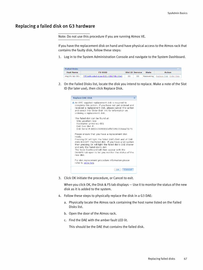
SysAdmin Basics
Replacing a failed disk on G3 hardware
Note: Do not use this procedure if you are running Atmos VE.
If you have the replacement disk on hand and have physical access to the Atmos rack that contains the faulty disk, follow these steps:
1. Log in to the System Administration Console and navigate to the System Dashboard.
2. On the Failed Disks list, locate the disk you intend to replace. Make a note of the Slot ID (for later use), then click Replace Disk.
3. Click OK initiate the procedure, or Cancel to exit.
When you click OK, the Disk & FS tab displays — Use it to monitor the status of the new disk as it is added to the system.
4. Follow these steps to physically replace the disk in a G3 DAE:
a. Physically locate the Atmos rack containing the host name listed on the Failed Disks list.
b. Open the door of the Atmos rack.
c. Find the DAE with the amber fault LED lit.
This should be the DAE that contains the failed disk.
Replacing failed disks 67
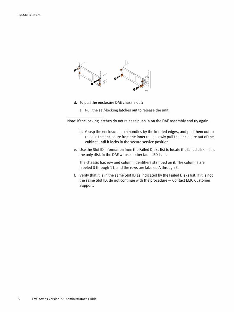
SysAdmin Basics
d. To pull the enclosure DAE chassis out:
a. Pull the self-locking latches out to release the unit.
Note: If the locking latches do not release push in on the DAE assembly and try again.
b. Grasp the enclosure latch handles by the knurled edges, and pull them out to release the enclosure from the inner rails; slowly pull the enclosure out of the cabinet until it locks in the secure service position.
e. Use the Slot ID information from the Failed Disks list to locate the failed disk — it is the only disk in the DAE whose amber fault LED is lit.
The chassis has row and column identifiers stamped on it. The columns are labeled 0 through 11, and the rows are labeled A through E.
f. Verify that it is in the same Slot ID as indicated by the Failed Disks list. If it is not the same Slot ID, do not continue with the procedure — Contact EMC Customer Support.
68 EMC Atmos Version 2.1 Administrator’s Guide
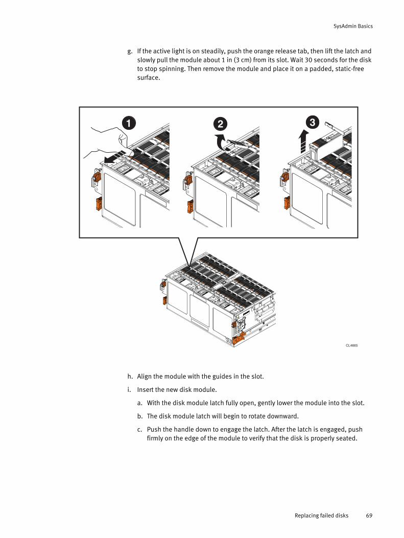
SysAdmin Basics
g. If the active light is on steadily, push the orange release tab, then lift the latch and slowly pull the module about 1 in (3 cm) from its slot. Wait 30 seconds for the disk to stop spinning. Then remove the module and place it on a padded, static-free surface.
h. Align the module with the guides in the slot.
i. Insert the new disk module.
a. With the disk module latch fully open, gently lower the module into the slot.
b. The disk module latch will begin to rotate downward.
c. Push the handle down to engage the latch. After the latch is engaged, push firmly on the edge of the module to verify that the disk is properly seated.
CL4665
2 31
Replacing failed disks 69
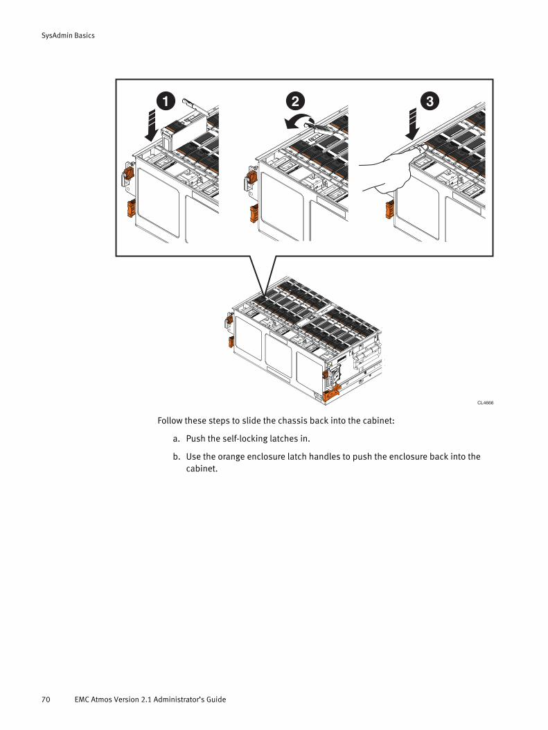
SysAdmin Basics
Follow these steps to slide the chassis back into the cabinet:
a. Push the self-locking latches in.
b. Use the orange enclosure latch handles to push the enclosure back into the cabinet.
CL4666
1 2 3
70 EMC Atmos Version 2.1 Administrator’s Guide
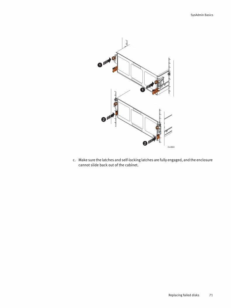
SysAdmin Basics
c. Make sure the latches and self-locking latches are fully engaged, and the enclosure cannot slide back out of the cabinet.
CL4664
2
2
1
1
Replacing failed disks 71

SysAdmin Basics
5. Use the Disk & FS tab to monitor the progress of the replacement.
Once you insert the disk, Atmos configures it. When the configuration completes, you see a new FS UUID and the Status as RUNNING, for example:
As the disk management subsystem configures the new disk, the Status transitions from NEW to CONFIGURING and finally to RUNNING, and the FSUUID is updated. Once the disk is in the RUNNING state, the disk replacement procedure is complete, and you can start another disk replacement operation (if required).
If the new disk is not detected, or does not transition to the RUNNING state in 15 minutes or less, contact EMC Customer Support for further assistance.
Once the failed disk process is complete, the original disk failure information is removed from the Disk Information view and moved to Disk Replacement History view available through the Service Only > Show Removed Disks page.
72 EMC Atmos Version 2.1 Administrator’s Guide
CHAPTER 4Configuring the Atmos System
This chapter describes how to access and configure system settings. It includes the following topics:
◆ Configuring the system master serial number.......................................................... 74◆ Configuring NTP (Network Time Protocol)................................................................. 74◆ Configuring DNS...................................................................................................... 76◆ Working with location groups.................................................................................. 77◆ Configuring web services security settings (system-wide)........................................ 80◆ Configuring data protection..................................................................................... 82
Configuring the Atmos System 73
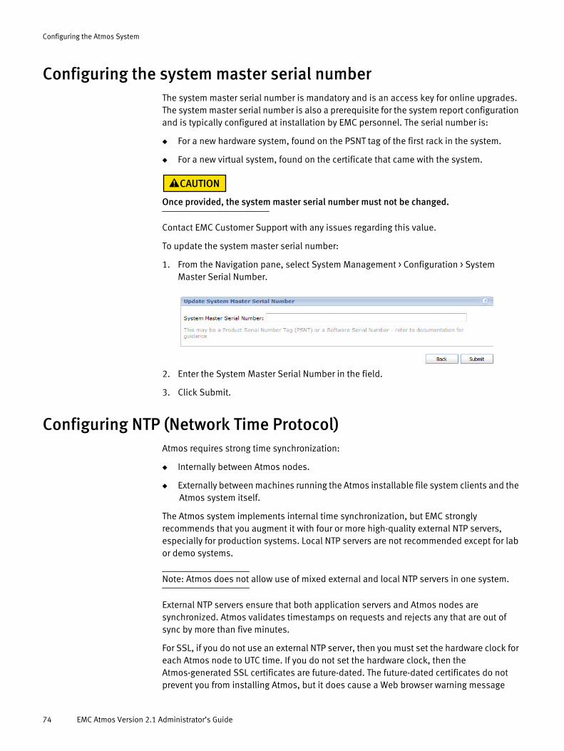
Configuring the Atmos System
Configuring the system master serial numberThe system master serial number is mandatory and is an access key for online upgrades. The system master serial number is also a prerequisite for the system report configuration and is typically configured at installation by EMC personnel. The serial number is:
◆ For a new hardware system, found on the PSNT tag of the first rack in the system.
◆ For a new virtual system, found on the certificate that came with the system.
Once provided, the system master serial number must not be changed.
Contact EMC Customer Support with any issues regarding this value.
To update the system master serial number:
1. From the Navigation pane, select System Management > Configuration > System Master Serial Number.
2. Enter the System Master Serial Number in the field.
3. Click Submit.
Configuring NTP (Network Time Protocol)Atmos requires strong time synchronization:
◆ Internally between Atmos nodes.
◆ Externally between machines running the Atmos installable file system clients and the Atmos system itself.
The Atmos system implements internal time synchronization, but EMC strongly recommends that you augment it with four or more high-quality external NTP servers, especially for production systems. Local NTP servers are not recommended except for lab or demo systems.
Note: Atmos does not allow use of mixed external and local NTP servers in one system.
External NTP servers ensure that both application servers and Atmos nodes are synchronized. Atmos validates timestamps on requests and rejects any that are out of sync by more than five minutes.
For SSL, if you do not use an external NTP server, then you must set the hardware clock for each Atmos node to UTC time. If you do not set the hardware clock, then the Atmos-generated SSL certificates are future-dated. The future-dated certificates do not prevent you from installing Atmos, but it does cause a Web browser warning message
74 EMC Atmos Version 2.1 Administrator’s Guide

Configuring the Atmos System
when you attempt to connect to the system administration user interface. The message displays every time you connect until the certificate is no longer post-dated. This can take up to 24 hours to resolve.
The external NTP servers should meet the following criteria:
◆ The NTP server must have a maximum stratum of 9 (where stratum 1 is the best possible), but it is recommended that you use an NTP server with stratum 1-5.
◆ The external NTP server must have a reliable network connection to Atmos.
◆ The NTP server must be NTP Version 4.
Note: Atmos does not support the use of Windows Domain Controllers as remote NTP time sources.
If an NTP server that meets the criteria is not available within the customer's company, consider allowing the Atmos system to use a well known public NTP server. In addition, you should configure at least three external NTP servers. This best practice guards against unavailability because of NTP server failures and maintenance windows.
Note: For machines running the Atmos IFS, or if you are using Atmos Web Services, EMC strongly recommends that you configure the Linux server running IFS to synchronize their time with the same NTP server that is used by Atmos.
To configure an NTP server:
1. Log in as SysAdmin.
2. From the Navigation pane, select System Management > Configuration > NTP.
3. Select the type of Configuration:
• Choose Default — to create or modify the NTP configuration for all RMGs that do not have an RMG-level configuration.
• Choose a specific RMG name — to modify the NTP configuration for that RMG.
• Click Add to create a new NTP configuration for an RMG:
4. Select the type of NTP Server:
Configuring NTP (Network Time Protocol) 75
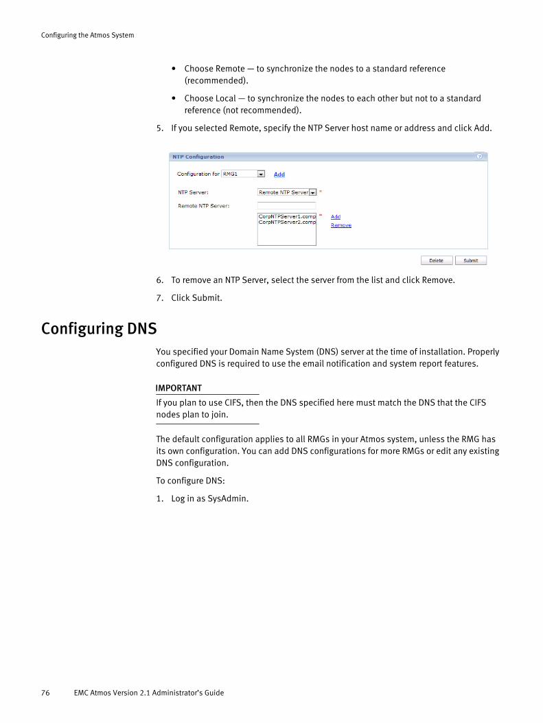
Configuring the Atmos System
• Choose Remote — to synchronize the nodes to a standard reference (recommended).
• Choose Local — to synchronize the nodes to each other but not to a standard reference (not recommended).
5. If you selected Remote, specify the NTP Server host name or address and click Add.
6. To remove an NTP Server, select the server from the list and click Remove.
7. Click Submit.
Configuring DNS You specified your Domain Name System (DNS) server at the time of installation. Properly configured DNS is required to use the email notification and system report features.
IMPORTANT
If you plan to use CIFS, then the DNS specified here must match the DNS that the CIFS nodes plan to join.
The default configuration applies to all RMGs in your Atmos system, unless the RMG has its own configuration. You can add DNS configurations for more RMGs or edit any existing DNS configuration.
To configure DNS:
1. Log in as SysAdmin.
76 EMC Atmos Version 2.1 Administrator’s Guide
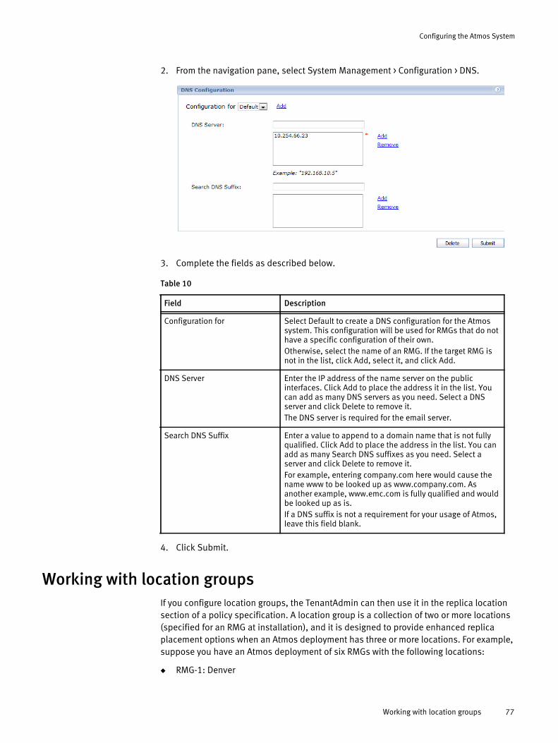
Configuring the Atmos System
2. From the navigation pane, select System Management > Configuration > DNS.
3. Complete the fields as described below.
4. Click Submit.
Working with location groupsIf you configure location groups, the TenantAdmin can then use it in the replica location section of a policy specification. A location group is a collection of two or more locations (specified for an RMG at installation), and it is designed to provide enhanced replica placement options when an Atmos deployment has three or more locations. For example, suppose you have an Atmos deployment of six RMGs with the following locations:
◆ RMG-1: Denver
Table 10
Field Description
Configuration for Select Default to create a DNS configuration for the Atmos system. This configuration will be used for RMGs that do not have a specific configuration of their own.Otherwise, select the name of an RMG. If the target RMG is not in the list, click Add, select it, and click Add.
DNS Server Enter the IP address of the name server on the public interfaces. Click Add to place the address it in the list. You can add as many DNS servers as you need. Select a DNS server and click Delete to remove it.The DNS server is required for the email server.
Search DNS Suffix Enter a value to append to a domain name that is not fully qualified. Click Add to place the address in the list. You can add as many Search DNS suffixes as you need. Select a server and click Delete to remove it.For example, entering company.com here would cause the name www to be looked up as www.company.com. As another example, www.emc.com is fully qualified and would be looked up as is.If a DNS suffix is not a requirement for your usage of Atmos, leave this field blank.
Working with location groups 77
Configuring the Atmos System
◆ RMG-2: Phoenix
◆ RMG-3: Atlanta
◆ RMG-4: Orlando
◆ RMG-5: Seattle
◆ RMG-6: San Francisco
A tenant’s business model might require that all objects with the .png extension are written only to Denver, Phoenix, and San Francisco. If you do not define a location group for this set of RMGs, the policies that the TenantAdmin writes cannot fulfill the business requirement. For example, without a location group, the TenantAdmin could define the replica location with the sameAs modifier like this:
◆ sameAs Denver OR sameAs San Francisco
In this case, the objects are never written to Phoenix. The otherThan modifier does not resolve as required either, for example:
◆ otherThan Orlando AND otherThan Seattle
This replica location expression does not prevent objects from being written to Atlanta.
However, once you define a location group that includes Denver, Phoenix, and San Francisco, the TenantAdmin can simply specify the location group in the replica expression. In this example, Denver, Phoenix, and San Francisco are in a location group called West so the replica location can simply be defined as:
◆ sameAs West
You can create location groups to organize RMG locations by country, region, continent, business unit, or any other groupings that make sense for your business.
Location group rules When specifying location groups, remember that:
◆ A location group must contain at least two locations.
◆ Atmos does not impose any restrictions on the contents of location groups, so location groups can have:
• The same contents as other location groups.
• A subset of the contents of other location groups.
• A superset of the contents of other location groups.
• One location can be specified in an unlimited number of location groups.
◆ Changes to a location group (create, modify, delete) can take up to 10 minutes to propagate to all of the nodes in the Atmos deployment.
◆ If a location group is used by a policy, it cannot be modified or deleted.
◆ Atmos does not impose an upper limit to the number of locations in a location group.
Listing location groups
To list location groups:
1. Log in as SysAdmin.
78 EMC Atmos Version 2.1 Administrator’s Guide

Configuring the Atmos System
2. From the navigation pane, select System Management > Configuration > Location Group.
Adding location groups
1. Log in as SysAdmin.
2. From the navigation pane, select System Management > Configuration > Location Group.
3. Click Add Group.
4. Specify a Location Group name that meets these rules:
• A string with a minium of 2 characters and a maximum of 255 characters.
• The first character in the name must be a letter.
• String can include letters, numbers, and the underscore character (_) only.
• Names are case-sensitive. The location group names a1 and A1 refer to different groups.
5. Select one or more locations to add to the group.
6. Click Save.
Atmos creates the group and distributes the group definition to the nodes in the system. This can take up to 10 minutes to complete. You will not be able to use the group in a policy specification until the distribution completes.
Modifying location groups
To modify existing location groups:
1. Log in as SysAdmin.
2. From the navigation pane, select System Management > Configuration > Location Group.
Working with location groups 79
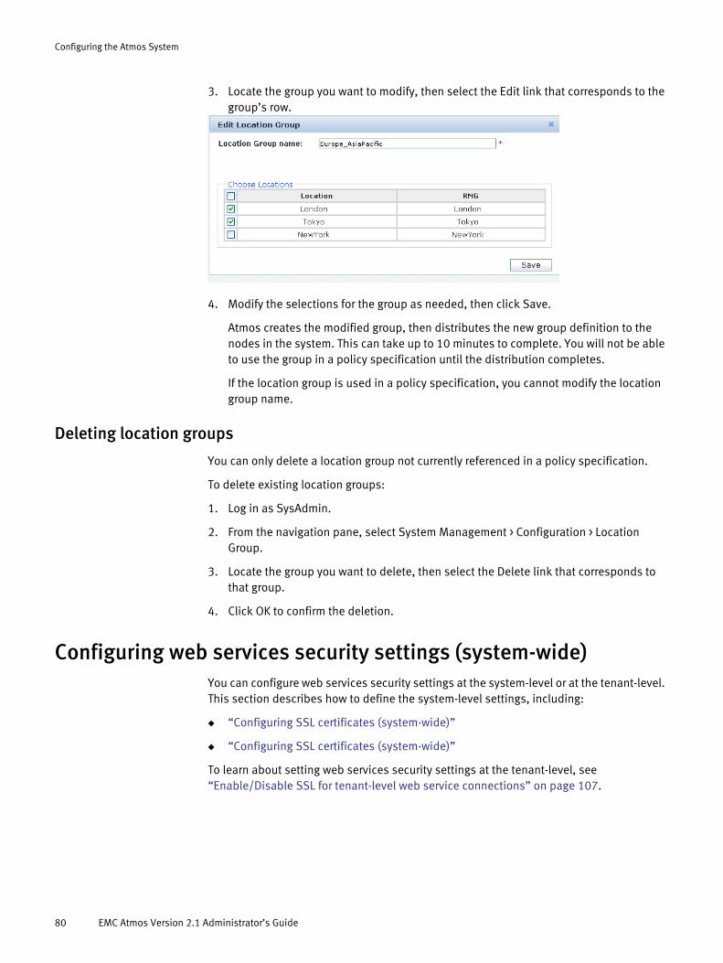
Configuring the Atmos System
3. Locate the group you want to modify, then select the Edit link that corresponds to the group’s row.
4. Modify the selections for the group as needed, then click Save.
Atmos creates the modified group, then distributes the new group definition to the nodes in the system. This can take up to 10 minutes to complete. You will not be able to use the group in a policy specification until the distribution completes.
If the location group is used in a policy specification, you cannot modify the location group name.
Deleting location groups
You can only delete a location group not currently referenced in a policy specification.
To delete existing location groups:
1. Log in as SysAdmin.
2. From the navigation pane, select System Management > Configuration > Location Group.
3. Locate the group you want to delete, then select the Delete link that corresponds to that group.
4. Click OK to confirm the deletion.
Configuring web services security settings (system-wide)You can configure web services security settings at the system-level or at the tenant-level. This section describes how to define the system-level settings, including:
◆ “Configuring SSL certificates (system-wide)”
◆ “Configuring SSL certificates (system-wide)”
To learn about setting web services security settings at the tenant-level, see “Enable/Disable SSL for tenant-level web service connections” on page 107.
80 EMC Atmos Version 2.1 Administrator’s Guide

Configuring the Atmos System
Configuring SSL certificates (system-wide)
Servers use certificates for creating an SSL while communicating with each other over networks. By default, Atmos uses a self-signed certificate for SSL connections. For the best security, EMC recommends you replace the default Atmos certificate with one of your own, signed by your trusted Certificate Authority (CA).
To configure your own SSL certificates for web services access on all nodes, follow the steps below. (To configure SSL certificates on all nodes assigned to a specific tenant, see “Configuring SSL certificates for a tenant” on page 107.)
1. Log in as SysAdmin.
2. From the navigation pane, select System Management > Configuration > Security > SSL.
3. Follow the procedure in “Configuring SSL certificates for a tenant” on page 107.
Enabling/Disabling SSL (system-wide)
If the Secure Sockets Layer (SSL) protocol on access nodes using Web Services is enabled, Atmos SOAP and REST interfaces can be accessed only by HTTPS. When Web Service SSL is disabled, Atmos SOAP and REST interfaces can be accessed by HTTP. By default, SSL is enabled.
SSL should be enabled unless one of the following is “true”:
◆ You secured the connection between the client and server in another way.
◆ Performance is more important than privacy protection for the data passing between the client and server (for example, if you are passing unimportant test data).
To change the SSL enablement setting for web services access on all nodes, follow these steps:
1. Log in as SysAdmin.
Configuring web services security settings (system-wide) 81
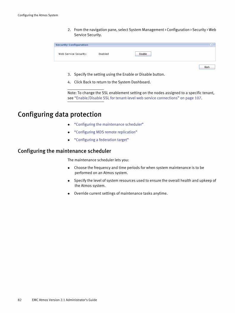
Configuring the Atmos System
2. From the navigation pane, select System Management > Configuration > Security > Web Service Security.
3. Specify the setting using the Enable or Disable button.
4. Click Back to return to the System Dashboard.
Note: To change the SSL enablement setting on the nodes assigned to a specific tenant, see “Enable/Disable SSL for tenant-level web service connections” on page 107.
Configuring data protection◆ “Configuring the maintenance scheduler”
◆ “Configuring MDS remote replication”
◆ “Configuring a federation target”
Configuring the maintenance scheduler
The maintenance scheduler lets you:
◆ Choose the frequency and time periods for when system maintenance is to be performed on an Atmos system.
◆ Specify the level of system resources used to ensure the overall health and upkeep of the Atmos system.
◆ Override current settings of maintenance tasks anytime.
82 EMC Atmos Version 2.1 Administrator’s Guide
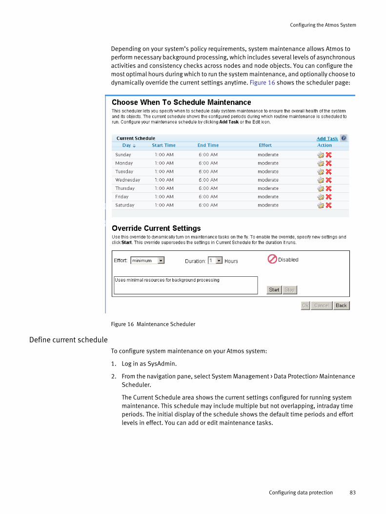
Configuring the Atmos System
Depending on your system’s policy requirements, system maintenance allows Atmos to perform necessary background processing, which includes several levels of asynchronous activities and consistency checks across nodes and node objects. You can configure the most optimal hours during which to run the system maintenance, and optionally choose to dynamically override the current settings anytime. Figure 16 shows the scheduler page:
Figure 16 Maintenance Scheduler
Define current scheduleTo configure system maintenance on your Atmos system:
1. Log in as SysAdmin.
2. From the navigation pane, select System Management > Data Protection> Maintenance Scheduler.
The Current Schedule area shows the current settings configured for running system maintenance. This schedule may include multiple but not overlapping, intraday time periods. The initial display of the schedule shows the default time periods and effort levels in effect. You can add or edit maintenance tasks.
Configuring data protection 83

Configuring the Atmos System
Table 11 describes the fields used in the maintenance scheduler:
3. To add/edit a maintenance task for a specific day, click Add Task or the Edit icon in Current Schedule to open the respective dialog box. An example of the Edit Task dialog box is shown:
4. In Start, select a day and start time from the list boxes to configure when the task begins.
5. In End, select an end time to indicate when the task stops. Note the display of total hours in the Duration field.
Table 11 Current schedule fields
Field Description
Day The Current Schedule area shows the current settings configured for running system maintenance. This schedule may include multiple but not overlapping, intraday time periods.
Start Time Local start time when maintenance begins for the selected day.
End Time Local end time when maintenance stops for the selected day.
Effort Level of system resources used to perform the maintenance tasks. A higher level increases the speed and volume of tasks running for each type of background processing. The effort level can be one of the following values:• Minimum: Uses minimal resources for background processing to maintain
system health.• Moderate: Uses moderate resources for background processing (for
example, when business activities are at non-peak levels).• Above avg: Uses above average resources for background processing (for
example, when business activities are normally at low levels).• Maximum: Uses the most resources allowed for background processing
(for example, when there is a maintenance backlog). This effort level allows the maximum amount of background tasks to run concurrently.
Action • Click the Edit icon to change the current time period and/or effort level for the selected day.
• Click X to delete the row.
Add Task Click Add Task to add a time period for a specific day. You can include multiple but not overlapping, intraday time periods.
? Click ? to display the maintenance scheduler help page.
84 EMC Atmos Version 2.1 Administrator’s Guide

Configuring the Atmos System
6. In Effort, select the effort level from the list box. The description of the selected effort level displays in the text box.
7. Click Submit to save the task. Atmos immediately refreshes the maintenance task in Current Schedule.
8. Click OK on the Maintenance Scheduler page to save the current screen configurations. (The Cancel button allows you to back out without saving any changes.)
Override current settingsThe Override Current Settings section lets you dynamically override the existing settings defined in Current Schedule once you specify and enable the feature. Adjusting system resources on the fly can provide a temporary boost to processing effort for either application operations or maintenance tasks. This override supersedes the settings in Current Schedule for the duration it runs. When the override duration ends or is stopped, maintenance on the normal schedule in Current Schedule resumes, as defined. If the duration of the override overlaps any portion of the configured time periods, Atmos deducts that time from the normal schedule.
To override current settings:
1. Log in as SysAdmin.
2. From the navigation pane, select System Management > Data Protection> Maintenance Scheduler.
3. In Effort in the Override Current Settings area, select the appropriate effort level from the list box. The description of the effort level you selected displays in the text box.
4. In Duration, enter the duration of the override in hours.
5. Click Start to enable Override Current Settings. The Override Enabled icon and Time Left in hours and minutes display.
Here is an example of an enabled override:
Configuring a federation target
If you configure a federation target, the TenantAdmin can define a policy with a replica in that targeted location, that is outside this Atmos system.
1. Log in as SysAdmin.
Configuring data protection 85

Configuring the Atmos System
2. From the navigation pane, select System Management > Data Protection> Federation. The Cloud Federations page appears initially empty, as shown below.
3. Click Add.
4. Fill out the fields on the page:
• Type — Currently, this always is Atmos onLine.
• Name — Specify a name for this target.
• Address — IP address, fully qualified domain name, or hostname for this target. (If a fully qualified domain name or hostname is used, it must be resolvable by Atmos nodes.)
• Full Token ID — A combination of subtenant ID and a UID within that subtenant, both in the Atmos onLine system that is being targeted. The format is subtenant ID/UID.
• Shared Secret — Shared secret for the UID, in the Atmos onLine system that is being targeted.
5. Click Submit. You are returned to the Cloud Federations page, which now shows the target you just configured.
Configuring MDS remote replication
When Atmos is installed, there are three MDS instances running on three different nodes in the same RMG in a master-slave-slave configuration. When Atmos is upgraded to Version 2.1, there are two MDS instances running on two different nodes in the same RMG in a master-slave configuration. The master MDS replicates its data to the slave MDS. The master MDS replicates its data to the MDS slaves. However, if the RMG that contains the master and slave nodes goes offline (for example, due to a power or network outage), all objects owned by the MDS set are unavailable to the user.
86 EMC Atmos Version 2.1 Administrator’s Guide

Configuring the Atmos System
The MDS remote replica feature enables you to configure a secondary installation segment to replicate metadata. If the primary RMG becomes unavailable, Atmos can read from the secondary RMG. To configure MDS remote replication, you must have two installation segments that reside in different RMGs; the installation segments must have the same number of nodes.
Atmos recommends that you perform this configuration
To configure MDS remote replication:
1. Log in as SysAdmin.
2. From the navigation pane, select System Management > Data Protection> MDS Remote Replication.
3. Select values for Installation Segment 1 and Installation Segment 2 from the drop-down lists.
The two installation segments must be in different RMGs. The GUI enforces this requirement: after you select Installation Segment 1, the drop-down list for Installation Segment 2 changes, so it does not contain any installation segments in the same RMG as Installation Segment 1.
4. Click Add.
Note: When you perform this configuration, the nodes in each IS transition to the degraded state while the MDS services are synchronizing. The amount of time needed to perform the synchronization depends on the amount of data in the system.
Configuring data protection 87

Configuring the Atmos System
88 EMC Atmos Version 2.1 Administrator’s Guide
CHAPTER 5Managing Tenants
This chapter describes how to manage tenants using the System Dashboard. It includes following topics:
◆ About tenants ......................................................................................................... 90◆ Listing tenants ........................................................................................................ 90◆ Creating tenants ..................................................................................................... 91◆ Renaming tenants................................................................................................... 99◆ Creating a TenantAdmin........................................................................................ 100◆ Deleting a TenantAdmin........................................................................................ 103◆ Assigning access nodes to a tenant ...................................................................... 104◆ Modifying access node assignments..................................................................... 106◆ Removing access node assignments ..................................................................... 106◆ Enable/Disable SSL for tenant-level web service connections ............................... 107◆ Configuring SSL certificates for a tenant................................................................ 107◆ Restricting Subtenant/UID data operations ........................................................... 109
Managing Tenants 89
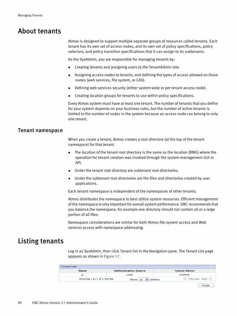
Managing Tenants
About tenantsAtmos is designed to support multiple separate groups of resources called tenants. Each tenant has its own set of access nodes, and its own set of policy specifications, policy selectors, and policy transition specifications that it can assign to its subtenants.
As the SysAdmin, you are responsible for managing tenants by:
◆ Creating tenants and assigning users to the TenantAdmin role.
◆ Assigning access nodes to tenants, and defining the types of access allowed on those nodes (web services, file system, or CAS).
◆ Defining web services security (either system-wide or per tenant access node).
◆ Creating location groups for tenants to use within policy specifications.
Every Atmos system must have at least one tenant. The number of tenants that you define for your system depends on your business rules, but the number of active tenants is limited to the number of nodes in the system because an access node can belong to only one tenant.
Tenant namespace
When you create a tenant, Atmos creates a root directory (at the top of the tenant namespace) for that tenant.
◆ The location of the tenant root directory is the same as the location (RMG) where the operation for tenant creation was invoked through the system-management GUI or API.
◆ Under the tenant root directory are subtenant root directories.
◆ Under the subtenant root directories are the files and directories created by user applications.
Each tenant namespace is independent of the namespaces of other tenants.
Atmos distributes the namespace to best utilize system resources. Efficient management of the namespace is very important for overall system performance. EMC recommends that you balance the namespace; for example one directory should not contain all or a large portion of all files.
Namespace considerations are similar for both Atmos file-system access and Web services access with namespace addressing.
Listing tenantsLog in as SysAdmin, then click Tenant list in the Navigation pane. The Tenant List page appears as shown in Figure 17.
90 EMC Atmos Version 2.1 Administrator’s Guide

Managing Tenants
Figure 17 Tenant List
The Name column shows the tenant ID. Each tenant has a unique ID that is required at login.
Creating tenants
Note: If you are running the Atmos LE, you are allowed to create one tenant.
1. Log in as SysAdmin, then click Create Tenant in the Navigation pane. The Create Tenant page appears.
2. Choose an Authentication Source (Local or Remote). This is used as the authentication source for users assigned to the TenantAdmin role for this tenant. The options are:
• Local — Authenticates users locally (internal) to the platform.
• Remote — Authentication users in an external LDAP server. Choose this option if your site requires external, centralized authentication. This option requires additional configuration as described in “Configuring an LDAP server as a remote authentication source” on page 92.
The Authentication Address field contains either a drop-down list (if LDAP servers are already configured) or a message: “No remote authentication source available,” as shown below. To configure an LDAP server, see “Configuring an LDAP server as a remote authentication source” on page 92.
3. Enter a Tenant Name. The Tenant Name has the following rules:
The tenant name must be unique. It can be up to 30 characters long, and can include alphanumeric characters and the following symbols:
underscore (_) @
dollar sign ($) caret (^)
Creating tenants 91

Managing Tenants
4. Select a UID Shared Secret Store Provider. For Atmos to authenticate REST and SOAP requests, Atmos must securely store the shared secrets associated with each UID. Atmos has two methods for storing UID shared secrets:
• LockBox — Atmos internal secret store (keystore). This is an encrypted file maintained on the Atmos nodes. It is ideal for small environments or test systems that do not have access to an external LDAP server. For environments where the number of UIDs exceed 500, it is recommended that shared secrets are stored in an external LDAP server.
• LDAP — External LDAP server. Only OpenLDAP 2.4 and AD are supported. The target LDAP server must be properly configured with schema extensions before it can be used. Each tenant must use a unique LDAP server or AD.
The shared secret is cached on the Atmos nodes. The cache is refreshed every 5 minutes.
5. If LDAP is selected as the UID shared secret store provider authentication source, complete the fields as described below.
6. Click Submit to create a tenant.
Note: When you create a tenant, Atmos automatically creates a default subtenant under it with the same name, ID, and Authentication Source as the tenant. You cannot delete the default subtenants.
Configuring an LDAP server as a remote authentication source
If you want TenantAdmins for this tenant to be authenticated by a remote authentication source, you might need to complete the Remote LDAP Configuration page (if one has not already been configured by the SecurityAdmin).
comma (,) parentheses ()
braces ([ ]) brackets ({ })
pipe (|)
Field Description
LDAP Servers The LDAP servers are where the secrets are stored. The format is: <ldap node1>:<port>[, <ldap node2>:<port>]... Note: There is no default port. The <port> must be specified.
Bind DN The binddn for the LDAP servers.For AD, the format is: cn=Administrator,cn=users,<base_dn> For example: cn=Administrator,cn=users,DC=MAUI,DC=CIG,DC=COM
Base Directory The base entry where the secrets stored.For AD the format is: cn=atmosks, <base_dn>For example:cn=atmosks,DC=MAUI,DC=CIG,DC=COM
Bind Password For OpenLDAP: the bindpw is the OpenLDAP administrator’s password.For AD: the bindpw is AD administrator's password.
92 EMC Atmos Version 2.1 Administrator’s Guide

Managing Tenants
Work with the administrator of the LDAP or Active Directory server to gather the configuration information in the following table.
Atmos Prompt Description Examples
Auth Name Use this field as a label a particular LDAP or AD server within the Atmos environment. This is especially useful when multiple remote servers are used within an Atmos system. For Active Directory, it is useful to choose the Domain name
ASD-CSE atmos.emc.com
Bind DN The Distinguished Name to use to connect to the LDAP server. This account should have: • Read access to the user objects in the LDAP
directory to search for user accounts.• Read access to the Base DN (for example,
DC=angsupport, DC=com) with the correct attribute used as the LDAP Login Name (for example, samAccountName)
• Read access to the group attributes in the LDAP directory
For Active Directory, this is typically the Admin-level user, their location in LDAP hierarchy and Domain.
cn=root,dc=host,dc=example,dc=com
or cn=Administrator, cn=Users,dc=ASD-CE, dc=TST
cn=admin,ou=atmos,dc=emc,dc=com
Bind password Password for Bind DN. For Active Directory this is the administrative level user’s password for the Active Directory server itself.
ChangeMe
Server Name LDAP server locations or IP addresses, separated by spaces.For Active Directory, this is the fully qualified domain name or IP address of the AD Server itself.
AD-Master.ASD-CSE.TSTor 10.245.33.133
LDAP Debug Level Debug level for the server.Setting it to zero prevents clear text passwords
0
Protocol LDAP
Note: LDAPS and TLS are not supported.
LDAP
Port Number Specify 389 for LDAP 389
LDAP Timeout Timeout interval (in milliseconds) to use when communicating with the LDAP server.0 = none and max = 2bn
30000
User Search path Distinguished Name (DN) where to begin User searches
cn=Users,dc=ASD-CSE,dc=TSTor ou=People,ou=atmos,dc=emc,dc=com
Group Search Path Distinguished Name (DN) where to begin Group searches
cn=Users,dc=ASD-CSE,dc=TSTor ou=Group,ou=atmos,dc=emc,dc=com
User Object Class Object class identifying users in the LDAP hierarchy
UserorposixAccount
Creating tenants 93

Managing Tenants
Note: Record this configuration information. You cannot edit or view it once the configuration completes.
Once you have all of your data, follow these steps in the Atmos System Administration Console:
1. Log in as SysAdmin, then click Create Tenant in the Navigation pane. The Create Tenant page appears
2. Select remote in the Authentication Source, then click Add. The Remote LDAP Configuration page appears.
User ID Attribute Attribute that identifies the user login ID within the user object.
cnuserPrincipalNameuid
Note: The User ID Attribute value (such as, cn) controls the LDAP user names that Atmos authenticates. When you are prompted by Atmos for a User Name, you must supply the value that corresponds with the User ID Attribute specified in the remote authentication configuration. This name must also meet the Atmos naming requirements described in “Atmos TenantAdmin naming rules” on page 100.
Group Object Class Object class identifying groups in the LDAP hierarchy.
Useror posixGroup
Group Member attributes
Attribute indicating group membership for a user within the group object
memberor gidNumber
Atmos Prompt Description Examples
94 EMC Atmos Version 2.1 Administrator’s Guide

Managing Tenants
3. Complete the fields by using the data you gathered from the LDAP administrator.
4. Click Save.
Configuring OpenLDAP for UID secret storage
Before using a new or existing OpenLDAP server as an external store for UID shared secrets, it must be configured with new schema information. The sections below describe how to download the schema scripts, configure the OpenLDAP servers, and start and stop the OpenLDAP servers.
Downloading the schema filesYou can download the ldapSecretStore.tar from the EMC Powerlink website:
http://www.powerlink.EMC.com
The ldapSecretStore.tar file contains the atmoskeystore.ldif file that will need to be available to each OpenLDAP server that is going to be configured.
Configuring existing OpenLDAP serversThis section describes how to configure existing OpenLDAP servers with the LDAP keystore (secret store) schema.
Creating tenants 95

Managing Tenants
Prerequisites:
◆ OpenLDAP 2.4.x is installed as documented by OpenLDAP.
◆ OpenLDAP 2.4.x is configured to run in dynamic configuration mode. For more information about dynamic configuration mode, see the OpenLDAP Administrator Guide.
◆ If the existing OpenLDAP servers are deployed in master/multiple-slaves mode, data synchronization must be configured.
◆ If there is a network firewall between the OpenLDAP server and the Atmos nodes, be sure to configure it to allow LDAP traffic to pass. The default LDAP port is 389.
◆ Download the schema scripts (ldapSecretStore.tar) from EMC Powerlink website.
◆ Ensure admin rights to the OpenLDAP server.
To integrate the schema scripts into OpenLDAP, follow the steps below:
1. Stop the existing OpenLDAP servers.
2. Untar the ldapSecretStore.tar file from the EMC Powerlink website and store the files in the following directories:
• /etc/maui/ldapkeyst/schema24.ldif
• /etc/maui/ldapkeyst/atmoskeystore.ldif
• /usr/local/maui/bin/ldapkeystcfg
3. Import the Atmos keystore schema into each OpenLDAP server using the following command:
ldapkeystcfg -i schema -d <slapd_conf_dir> -f<path_of_atmoskeystore.ldif>
For example:
ldapkeystcfg -i schema -d /etc/openldap/slapd.d -fatmoskeystore.ldif
4. Restart all of the OpenLDAP servers.
5. Add the Atmos keystore root entry into the master OpenLDAP server using the following command:
ldapkeystcfg -i rootentry -r <bind_dn> -b <base_dn> [-p <ldap_port>]
For example:
ldapkeystcfg -i rootentry -r cn=admin,ou=atmos,dc=emc,dc=com -bdc=emc,dc=com
Note: The entries derived from <base_dn> should already be configured to be able to synchronize the OpenLDAP servers.
Configuring new OpenLDAP serversThis section describes how to configure new OpenLDAP servers with the LDAP keystore schema. These steps assume that the OpenLDAP software is installed.
Prerequisites:
96 EMC Atmos Version 2.1 Administrator’s Guide
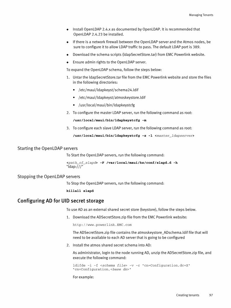
Managing Tenants
◆ Install OpenLDAP 2.4.x as documented by OpenLDAP. It is recommended that OpenLDAP 2.4.23 be installed.
◆ If there is a network firewall between the OpenLDAP server and the Atmos nodes, be sure to configure it to allow LDAP traffic to pass. The default LDAP port is 389.
◆ Download the schema scripts (ldapSecretStore.tar) from EMC Powerlink website.
◆ Ensure admin rights to the OpenLDAP server.
To expand the OpenLDAP schema, follow the steps below:
1. Untar the ldapSecretStore.tar file from the EMC Powerlink website and store the files in the following directories:
• /etc/maui/ldapkeyst/schema24.ldif
• /etc/maui/ldapkeyst/atmoskeystore.ldif
• /usr/local/maui/bin/ldapkeystcfg
2. To configure the master LDAP server, run the following command as root:
/usr/local/maui/bin/ldapkeystcfg -m
3. To configure each slave LDAP server, run the following command as root:
/usr/local/maui/bin/ldapkeystcfg -s -l <master_ldapserver>
Starting the OpenLDAP serversTo Start the OpenLDAP servers, run the following command:
<path_of_slapd> -F /var/local/maui/ks/conf/slapd.d -h"ldap:///"
Stopping the OpenLDAP serversTo Stop the OpenLDAP servers, run the following command:
killall slapd
Configuring AD for UID secret storage
To use AD as an external shared secret store (keystore), follow the steps below.
1. Download the ADSecretStore.zip file from the EMC Powerlink website:
http://www.powerlink.EMC.com
The ADSecretStore.zip file contains the atmoskeystore_ADschema.ldif file that will need to be available to each AD server that is going to be configured
2. Install the atmos shared secret schema into AD:
As administrator, login to the node running AD, unzip the ADSecretStore.zip file, and execute the following command:
ldifde -i -f <schema file> -v -c "cn=Configuration,dc=X""cn=Configuration,<base dn>"
For example:
Creating tenants 97
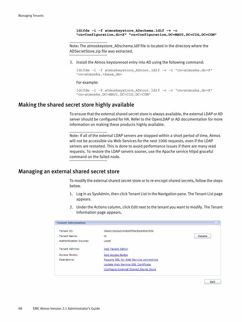
Managing Tenants
ldifde -i -f atmoskeystore_ADschema.ldif -v -c"cn=Configuration,dc=X" "cn=Configuration,DC=MAUI,DC=CIG,DC=COM"
Note: The atmoskeystore_ADschema.ldif file is located in the directory where the ADSecretStore.zip file was extracted.
3. Install the Atmos keystoreroot entry into AD using the following command:
ldifde -i -f atmoskeystore_ADroot.ldif -v -c "cn=atmosks,dc=X""cn=atmosks,<base_dn>
For example:
ldifde -i -f atmoskeystore_ADroot.ldif -v -c "cn=atmosks,dc=X""cn=atmosks,DC=MAUI,DC=CIG,DC=COM"
Making the shared secret store highly available
To ensure that the external shared secret store is always available, the external LDAP or AD server should be configured for HA. Refer to the OpenLDAP or AD documentation for more information on making these products highly available.
Note: If all of the external LDAP servers are stopped within a short period of time, Atmos will not be accessible via Web Services for the next 1000 requests, even if the LDAP servers are restarted. This is done to avoid performance issues if there are many read requests. To restore the LDAP servers sooner, use the Apache service httpd graceful command on the failed node.
Managing an external shared secret store
To modify the external shared secret store or to re-encrypt shared secrets, follow the steps below.
1. Log in as SysAdmin, then click Tenant List in the Navigation pane. The Tenant List page appears.
2. Under the Actions column, click Edit next to the tenant you want to modify. The Tenant Information page appears.
98 EMC Atmos Version 2.1 Administrator’s Guide
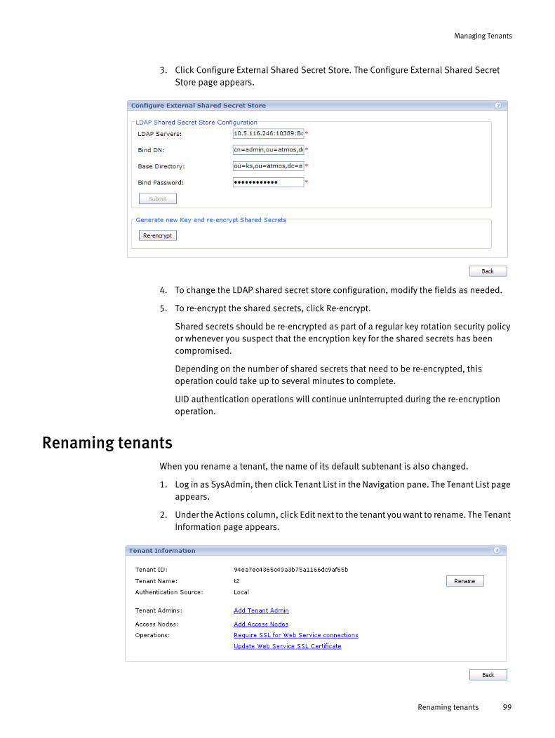
Managing Tenants
3. Click Configure External Shared Secret Store. The Configure External Shared Secret Store page appears.
4. To change the LDAP shared secret store configuration, modify the fields as needed.
5. To re-encrypt the shared secrets, click Re-encrypt.
Shared secrets should be re-encrypted as part of a regular key rotation security policy or whenever you suspect that the encryption key for the shared secrets has been compromised.
Depending on the number of shared secrets that need to be re-encrypted, this operation could take up to several minutes to complete.
UID authentication operations will continue uninterrupted during the re-encryption operation.
Renaming tenantsWhen you rename a tenant, the name of its default subtenant is also changed.
1. Log in as SysAdmin, then click Tenant List in the Navigation pane. The Tenant List page appears.
2. Under the Actions column, click Edit next to the tenant you want to rename. The Tenant Information page appears.
Renaming tenants 99

Managing Tenants
3. Click Rename. The Rename Tenant page appears.
4. Enter the New Tenant Name, then click Submit.
Creating a TenantAdminUsers assigned to the TenantAdmin role can be authenticated against the internal authentication source maintained by the Atmos system (called local authentication) or an external authentication source maintained by the customer (called remote authentication). If remote authentication was specified when the tenant was created, then any TenantAdmin assigned to the tenant must use be authenticated by the remote source.
A tenant can have multiple TenantAdmins, but a TenantAdmin can be a TenantAdmin for only one tenant.
Note: For operations that create/modify system-management users, or assign an administrative role (SysAdmin, TenantAdmin, or SubtenantAdmin) to a user, there is a slight delay before the effect of the operation is visible on all Atmos nodes, while the Atmos system is synchronized.
Atmos TenantAdmin naming rules
The TenantAdmin name can include up to 255 alphanumeric characters and the following symbols:
The System Administration Console enforces these rules for both local and remote authentication.
User names (for local authentication) are NOT case-sensitive. For example, TenantADMIN is equivalent to TenantAdmin.
Assigning the TenantAdmin role using local authentication
Follow these steps to create a TenantAdmin for a tenant that uses local authentication:
underscore (_) @
dollar sign ($) caret (^)
comma (,) parentheses ()
braces ([ ]) brackets ({ })
100 EMC Atmos Version 2.1 Administrator’s Guide

Managing Tenants
1. Log in as SysAdmin, then click Tenant List in the Navigation pane.
2. Click the tenant name.
3. Click Add Tenant Admin. The Add New Admin page appears.
4. Enter the User Name for this TenantAdmin, and click Save.
If the user does not already exist, it prompts you to add the user.
Creating a TenantAdmin 101

Managing Tenants
5. Click OK to add the new (local) user to the system. You are prompted to enter the password and other information about the account.
6. Enter the required Password and Password Confirm fields and any optional fields.
Although the Email field is optional, we highly recommend you use it. If the new TenantAdmin forgets his password, he can get it emailed to him — but only if you fill in this field.
7. Click Save to return to the Tenant Information page. The Tenant Admins area shows the new TenantAdmin’s user name.
Assigning the TenantAdmin role using remote authentication
Follow these steps to create a TenantAdmin for a tenant that uses remote authentication:
1. Work with the LDAP administrator to obtain the valid LDAP user name that you want to assign to the Atmos TenantAdmin role.
102 EMC Atmos Version 2.1 Administrator’s Guide

Managing Tenants
Note: The User ID Attribute value (such as, cn) controls the LDAP user names that Atmos authenticates. When you are prompted by Atmos for a User Name, you must supply the value that corresponds with the User ID Attribute specified in the remote authentication configuration. In addition, this name must also meet the Atmos naming requirements described in “Atmos TenantAdmin naming rules” on page 100.
2. Log in as SysAdmin, then click Tenant List in the Navigation pane. The Tenant List page appears.
3. Click Edit for the Tenant you need to modify. The Tenant Information page appears.
4. Click Add Tenant Admin. The Add New Admin page appears.
5. Enter the User Name, then click Save.
Deleting a TenantAdminThis operation removes the user from the TenantAdmin role, but it does not delete the user from the local or remote authentication source.
1. Log in as SysAdmin, then click Tenant List in the Navigation pane. The Tenant List page appears.
Deleting a TenantAdmin 103
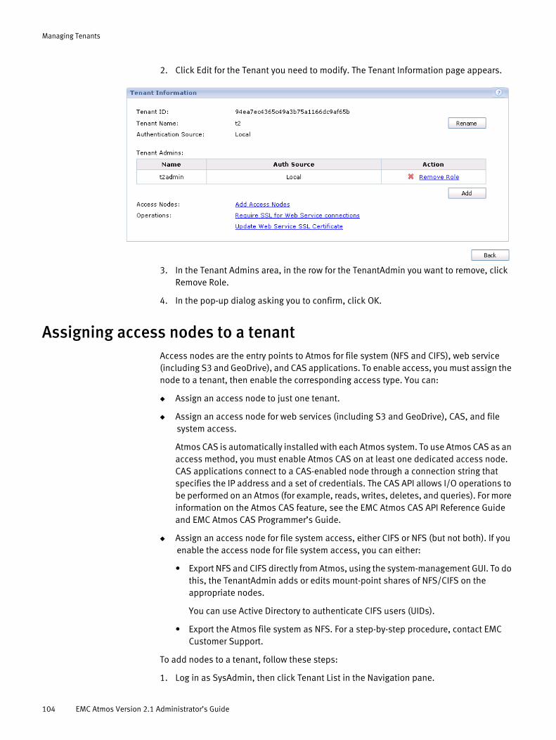
Managing Tenants
2. Click Edit for the Tenant you need to modify. The Tenant Information page appears.
3. In the Tenant Admins area, in the row for the TenantAdmin you want to remove, click Remove Role.
4. In the pop-up dialog asking you to confirm, click OK.
Assigning access nodes to a tenantAccess nodes are the entry points to Atmos for file system (NFS and CIFS), web service (including S3 and GeoDrive), and CAS applications. To enable access, you must assign the node to a tenant, then enable the corresponding access type. You can:
◆ Assign an access node to just one tenant.
◆ Assign an access node for web services (including S3 and GeoDrive), CAS, and file system access.
Atmos CAS is automatically installed with each Atmos system. To use Atmos CAS as an access method, you must enable Atmos CAS on at least one dedicated access node. CAS applications connect to a CAS-enabled node through a connection string that specifies the IP address and a set of credentials. The CAS API allows I/O operations to be performed on an Atmos (for example, reads, writes, deletes, and queries). For more information on the Atmos CAS feature, see the EMC Atmos CAS API Reference Guide and EMC Atmos CAS Programmer’s Guide.
◆ Assign an access node for file system access, either CIFS or NFS (but not both). If you enable the access node for file system access, you can either:
• Export NFS and CIFS directly from Atmos, using the system-management GUI. To do this, the TenantAdmin adds or edits mount-point shares of NFS/CIFS on the appropriate nodes.
You can use Active Directory to authenticate CIFS users (UIDs).
• Export the Atmos file system as NFS. For a step-by-step procedure, contact EMC Customer Support.
To add nodes to a tenant, follow these steps:
1. Log in as SysAdmin, then click Tenant List in the Navigation pane.
104 EMC Atmos Version 2.1 Administrator’s Guide

Managing Tenants
2. Click Edit for the Tenant you need to modify.
3. Under Access Nodes, click Add Access Nodes.
Note: The node IP address is shown rather than the tenant access IP address.
4. On the left, select the check boxes for the nodes to add to the tenant.
5. For each selected node, check the access type for the node (Web Service, and/or a File System, and/or CAS, as required.
6. Check Multi Subtenant Access if you want all subtenants under this tenant to have access to the namespace via the selected nodes). If you do not check this, only the default subtenant under this tenant will have access.
Assigning access nodes to a tenant 105

Managing Tenants
7. Click Save. You are returned to the Tenant Information page. The selected node name now appears in the Access Nodes list for the tenant you modified.
Modifying access node assignments1. Log in as SysAdmin. On the Tenant List page, click Edit for the tenant whose services
you want to modify.
2. At the Tenant Information page for the selected tenant, click Edit in the row of the access node to modify.
3. Enable or disable the services as needed, then click Save to complete the operation.
Note: At least one service must be enabled.
Removing access node assignmentsTo remove the node assignment from a tenant:
1. Log in as SysAdmin. On the Tenant List page, click Edit for the tenant whose access nodes assignments you want to remove.
2. At the Tenant Information page for the selected tenant, click Remove in the row of the access node to remove.
3. Click OK to complete the removal.
Note: Disabling access stops the corresponding service (such as web services or CAS service) from running on the node.
106 EMC Atmos Version 2.1 Administrator’s Guide

Managing Tenants
Enable/Disable SSL for tenant-level web service connectionsUse Require SSL for Web Service connections on the Tenant Information page to enable and disable the Secure Sockets Layer (SSL) protocol on access nodes using web services. When enabled, Atmos SOAP and REST interfaces can only be accessed by HTTPS (plain HTTP requests are refused). When disabled, Atmos SOAP and REST interfaces can be accessed by HTTP and HTTPS.
SSL should be enabled unless one of the following is true:
◆ You secured the connection between the client and server in another way.
◆ Performance is more important than privacy protection for the data passing between the client and server (for example, if you are passing unimportant test data).
To change the SSL enablement setting for web service access on all nodes assigned to this tenant, follow the steps below.
Note: To change the SSL enablement setting for Web-service access on all nodes, see “Configuring SSL certificates (system-wide)” on page 81.
1. Go to the Tenant Information page, click Require SSL for Web Service connections.
Note: This link always is active, but if you click it before any node is assigned to the tenant for Web Service access, you get an error message.
2. Specify the setting using the Enable or Disable button (whichever is active).
3. Click Back to return to the Tenant Information page.
Configuring SSL certificates for a tenantServers use certificates for creating an SSL while communicating with each other over networks. By default, Atmos uses a self-signed certificate for SSL connections. For the best security, we recommend you replace the default Atmos certificate with one of your own, signed by your trusted Certificate Authority (CA).
To configure your own SSL certificates for Web-service access on all nodes assigned to this tenant, follow the steps below.
Note: To configure SSL certificates for all nodes, go to the System Dashboard, click SSL Configuration (in the Operations area), then go to Step 2 below.
Enable/Disable SSL for tenant-level web service connections 107

Managing Tenants
1. On the Tenant Information page, click Update Web Service SSL Certificate (in the Operations area). The Update Web Service SSL Certificate page appears.
2. Select the type of Server Certificate you want. This selection applies only to the format of the Server Certificate File.
• PKCS7— server certificate sent to a CA for requesting a public-key certificate
• PKCS12—server certificate file format commonly used to store private keys with accompanying public key certificates and are protected with a password-based symmetric key
3. Depending on the type of Server Certificate selected PKCS7 or PKCS12), different fields appear on the page. Complete the fields as described below.
PKCS7 Fields Description
Certificate Key File A file which stores the PEM-encoded RSA Private Key.
Certificate Key Password The secret to unencrypt the Certificate Key File. If this is not provided, the non-encrypted private key is accepted.
Server Certificate File A PEM-encoded file that contains the server’s certificate. The Server Certificate File contains just the certificate.
Certificate of Trusted Root CA The public certificate of the trusted root CA certificate. This is the certificate that Atmos trusts. All clients that communicate with Atmos must present a certificate signed by the same CA or signed by a CA that can be linked back to the trusted CA.
Certificate Chain of CAs A file that contains a set of certificates that allows the SSL protocol to check and validate the integrity of the certificate presented to it. The root CA certificate must be the first certificate in the chain file, followed by one or more intermediary CA certificates.
108 EMC Atmos Version 2.1 Administrator’s Guide

Managing Tenants
4. Click Submit.
Restricting Subtenant/UID data operationsYou might want to disable subtenants or UIDs from performing create, update, or delete operations under certain conditions. For example, suppose you want to limit a subtenant’s UIDs to 10GB of storage each. When the UIDs reach the 10GB limit, you want to restrict them from adding new data or modifying existing data, but you still allow them to read or delete their data.
Atmos supports the following data operation restrictions:
◆ “Restricting Subtenants or UIDs to read and delete operations”
◆ “Restricting UIDs to read-only operations”
Note: If you want to use this feature to disable subtenants and UIDs because they have gone over their storage quota, you must perform the calculations to determine the over-quota conditions specific to your business. Atmos does not perform this calculation.
EMC recommends that you use SSH public key authentication while performing the procedures described in this section.
Restricting Subtenants or UIDs to read and delete operations
To disable all data operations except read and delete requests for one or more subtenants or UIDs, perform these steps:
1. Gather the following information:
• The list of subtenants/UIDs whose activities you want to restrict.
• If ACDP is present, obtain the list of ACDP web services nodes. You can gather the nodes list by node name or IP address.
PKCS12 Fields Description
Server Certificate File A file which stores the PEM-encoded file that contains the server’s certificate. The Server Certificate File contains both the certificate and the private key.
Password A symmetric key password use to protect the private key for the PKCS12 certificate.
Certificate of Trusted Root CA The public certificate of the trusted root CA certificate. This is the certificate that Atmos trusts. All clients that communicate with Atmos must present a certificate signed by the same CA or signed by a CA that can be linked back to the trusted CA.
Certificate Chain of CAs\ A file that contains a set of certificates that allows the SSL protocol to check and validate the integrity of the certificate presented to it. The root CA certificate must be the first certificate in the chain file, followed by one or more intermediary CA certificates.
Restricting Subtenant/UID data operations 109

Managing Tenants
2. Create a file that contains the subtenants and UIDs to restrict. You can use the text editor of your choice, but the file must meet the following requirements:
• The file must be named overquota.txt.
• It must reside in /etc/maui/.
• It must be formatted with one subtenant ID or one subtenantID/UID per line, for example:
87b52b79008b4a95bba3815a7924ad21/testcases87b52b79008b4a95bba3815a7924ad21/testcases218942e79008b4a95bba3815a7924a343
3. Log in to the Atmos node where you created and stored the overquota.txt file, then run the following command to distribute the overquota.txt file to each Atmos node:
# config_overquota -f overquota.txt
Note: This command distributes the file to each node, then gracefully restarts the apache server on each Atmos node to ensure that the most up-to-date overquota.txt file is loaded.
4. If ACDP is present:
a. Use scp to distribute the overquota.txt file to each of the ACDP web services nodes for example:
scp overquota.txt root@<wsnode>:/etc/maui/overquota.txt
b. Perform a graceful restart of the Apache service to ensure that each ACDP web services node uses the updated overquota.txt file, by running this command on each ACDP web services node:
# ssh root@<wsnode> apache2 reload
Restricting UIDs to read-only operations
Follow this procedure to disable all data operations except GET requests for one or more UIDs:
1. Gather the following information:
• The list of UIDs whose activities you want to restrict.
• If ACDP is present, obtain the list of ACDP web services nodes.
2. Create a file that contains the subtenants and UIDs to restrict. You can use the text editor of your choice, but the file must meet the following requirements:
• The file must be named readonly.txt.
• It must reside in /etc/maui/.
• It must be formatted with one subtenantID/UID per line, for example:
87b52b79008b4a95bba3815a7924ad21/UID187b52b79008b4a95bba3815a7924ad21/UID2
3. Log in to the Atmos node where you created the readonly.txt file, then run the following command to distribute the readonly.txt file to each Atmos node:
# config_readonly -f readonly.txt
110 EMC Atmos Version 2.1 Administrator’s Guide
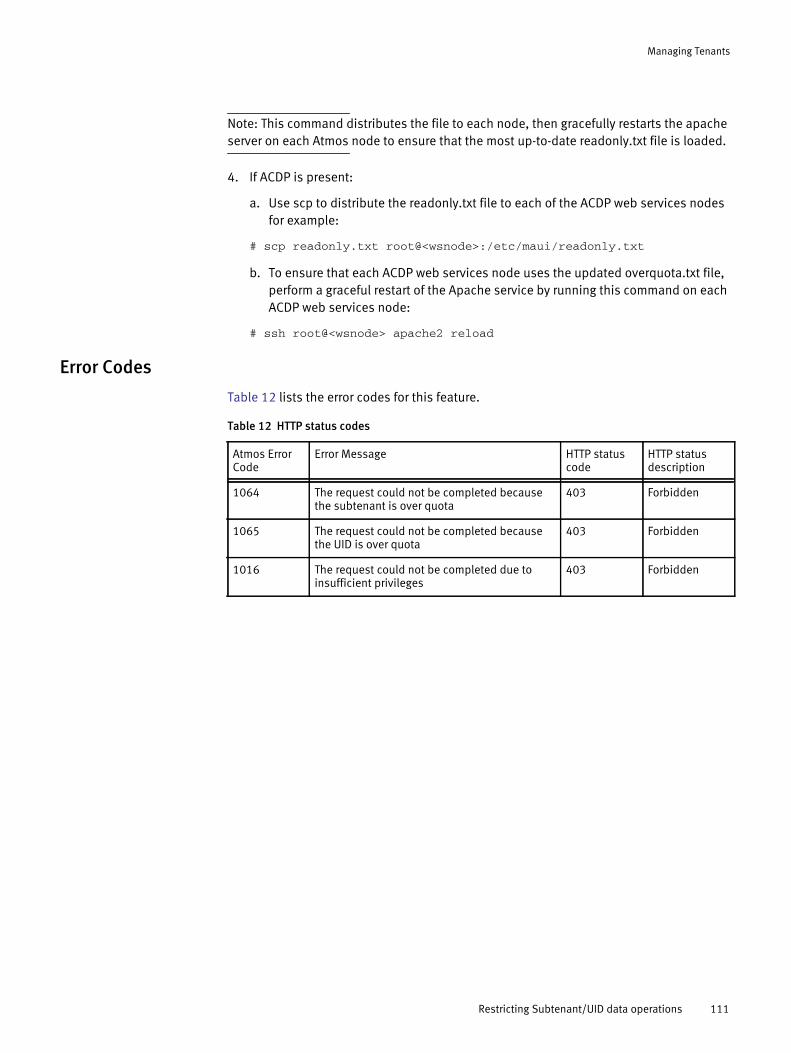
Managing Tenants
Note: This command distributes the file to each node, then gracefully restarts the apache server on each Atmos node to ensure that the most up-to-date readonly.txt file is loaded.
4. If ACDP is present:
a. Use scp to distribute the readonly.txt file to each of the ACDP web services nodes for example:
# scp readonly.txt root@<wsnode>:/etc/maui/readonly.txt
b. To ensure that each ACDP web services node uses the updated overquota.txt file, perform a graceful restart of the Apache service by running this command on each ACDP web services node:
# ssh root@<wsnode> apache2 reload
Error Codes
Table 12 lists the error codes for this feature.
Table 12 HTTP status codes
Atmos Error Code
Error Message HTTP status code
HTTP status description
1064 The request could not be completed because the subtenant is over quota
403 Forbidden
1065 The request could not be completed because the UID is over quota
403 Forbidden
1016 The request could not be completed due to insufficient privileges
403 Forbidden
Restricting Subtenant/UID data operations 111

Managing Tenants
112 EMC Atmos Version 2.1 Administrator’s Guide
CHAPTER 6System Monitoring, Events, & Reporting
This chapter describes how to configure and use Atmos system monitoring, event notifications, system reporting, and log collection. It includes the following topics:
◆ Overview............................................................................................................... 114◆ Notification policy................................................................................................. 114◆ Email notifications ................................................................................................ 116◆ Monitoring Atmos with your NMS .......................................................................... 117◆ System reports...................................................................................................... 128◆ Log files and log collection.................................................................................... 138◆ Remote log files .................................................................................................... 139◆ Monitoring events................................................................................................. 140◆ Troubleshooting disk management events ............................................................ 143
System Monitoring, Events, & Reporting 113
System Monitoring, Events, & Reporting
OverviewAtmos provides various types of system events that can be expressed as messages in logs, emails, and SNMP traps as well as collected in system reports (SYR). These messages help you maintain and troubleshoot your Atmos system.
Atmos provides the following types of event notifications:
◆ Log entries — created when system events result in warnings, errors, and critical conditions, or simply to log useful information. Events may come from either hardware or software. The Atmos System Administration Console and Tenant Administration Console displays searchable event information for SysAdmins and TenantAdmins.
◆ Email notifications — can be triggered and sent based on severity. Email notifications can be configured at the system level and the RMG level.
◆ SNMP — both SNMP trap generation and SNMP standard (MIB-II) MIB access are supported. For MIB access, the SNMP agent must be configured.
◆ System Report (SYR) — can pass event notifications to EMC.
Atmos also provides log collection and system reports, which are used by EMC Technical Support when troubleshooting:
◆ Log collection — collects logs for debugging purposes. After the logs are collected, you can save the log package and send them to EMC Technical Support.
◆ System report — collects data about your Atmos configuration and sends a report to the EMC System Reports database through the System Report (SYR) mechanism. System reports improve customer service and allow EMC to provide timely support for Atmos issues.
This guide provides appendices with more information about individual events and SNMP traps:
◆ Atmos Event Reference ......................................................................................... 239◆ Atmos MIB ............................................................................................................ 267◆ MIB-II (RFC 1213) .................................................................................................. 291◆ Host Resources MIB (RFC 2790) ............................................................................ 327
Notification policyAtmos notification policy allows you to enable or disable notification services at the system level. The services are:
◆ SNMP trap notifications
◆ Email notifications
◆ Remote syslog (system log) collection
To configure notification policy:
1. Log in as SysAdmin.
114 EMC Atmos Version 2.1 Administrator’s Guide

System Monitoring, Events, & Reporting
2. From the Navigation pane, select System Management > Configuration > Notification > Notification Policy.
3. To enable SNMP traps, check Enable SNMP and set the severity drop-down to Information, Warning, Error, or Critical. Your SNMP node can now receive notification of events equal to or higher than your severity setting. Complete the SNMP configuration tasks found in this chapter to finish SNMP set up.
4. To enable email notification, check Enable Email and set the severity drop-down to Information, Warning, Error, or Critical. Your email accounts can now receive email notification of events equal to or higher than your severity setting. Complete the email configuration tasks found in this chapter to finish email set up.
5. To enable the remote syslog to receive event notifications, check Enable remote syslog. Remote syslog can now receive all event notifications after you complete the remote syslog configuration tasks found in this chapter.
6. Click Submit.
Testing notifications
After you have completed system monitoring configuration, you can test your configuration.
1. Return to the Notification Policy page and click Test. The Test Notification popup describes the test process.
2. Click Send to send a test event to your configured services. A message about the status of the test request appears in the dialog box.
3. Check your configured services to see if you received the following test event notification: 59999 GUI test event.
Notification policy 115
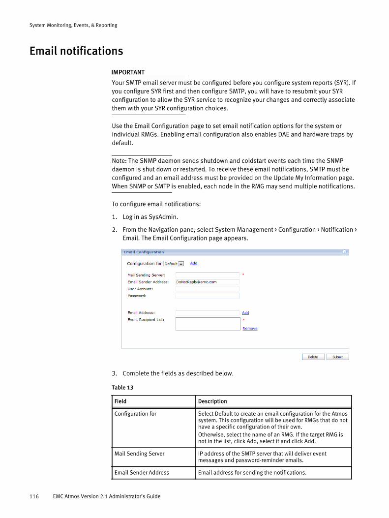
System Monitoring, Events, & Reporting
Email notifications
IMPORTANT
Your SMTP email server must be configured before you configure system reports (SYR). If you configure SYR first and then configure SMTP, you will have to resubmit your SYR configuration to allow the SYR service to recognize your changes and correctly associate them with your SYR configuration choices.
Use the Email Configuration page to set email notification options for the system or individual RMGs. Enabling email configuration also enables DAE and hardware traps by default.
Note: The SNMP daemon sends shutdown and coldstart events each time the SNMP daemon is shut down or restarted. To receive these email notifications, SMTP must be configured and an email address must be provided on the Update My Information page. When SNMP or SMTP is enabled, each node in the RMG may send multiple notifications.
To configure email notifications:
1. Log in as SysAdmin.
2. From the Navigation pane, select System Management > Configuration > Notification > Email. The Email Configuration page appears.
3. Complete the fields as described below.
Table 13
Field Description
Configuration for Select Default to create an email configuration for the Atmos system. This configuration will be used for RMGs that do not have a specific configuration of their own.Otherwise, select the name of an RMG. If the target RMG is not in the list, click Add, select it and click Add.
Mail Sending Server IP address of the SMTP server that will deliver event messages and password-reminder emails.
Email Sender Address Email address for sending the notifications.
116 EMC Atmos Version 2.1 Administrator’s Guide

System Monitoring, Events, & Reporting
4. Click Submit.
Monitoring Atmos with your NMSYour network management station (NMS) should be the central monitoring tool for Atmos. The NMS should be configured to receive the Atmos SNMP traps from the Event Manager and to poll various Atmos and MIB-II MIB objects in order to properly monitor the Atmos hardware and software.
For complete monitoring, a combination of traps and MIB objects must be monitored, such as:
◆ Monitoring engine traps — monitors Atmos system resources and provides SNMP trap notifications of unfavorable system conditions. For more information, see “SNMP support.”
◆ Dell hardware traps — Atmos forwards Dell OpenManage hardware SNMP traps for all severities (information, warning, error, and critical). These traps provide an indication of the node status. For more information about Dell hardware traps, see “Dell traps.”
◆ Atmos MIB — provides detailed information on node storage capacity, DAE storage capacity, Atmos service status, MDS status, SS status, WS status, JS status, and so on. For more information about the Atmos MIB, see Appendix B, “Atmos MIB.”
◆ MIB-II MIB — provides detailed information about the network interfaces. For more information about the MIB-II MIB, see Appendix C, “MIB-II (RFC 1213).”
◆ Host Resources MIB — provides detailed information about the number of disks in the Atmos system, the total storage for all disks, the total storage for a given disk, the total used storage for all disks, and so on. For more information about the Host Resources MIB, see Appendix D, “Host Resources MIB (RFC 2790).”
SNMP support
Atmos supports both SNMP trap generation and SNMP standard (MIB-II) MIB access. For MIB access, the SNMP agent must be configured. SNMP traps and the SNMP agent can be configured at the same time or separately. For better security, choose an SNMP agent community name other than public or private.
User Account The user name of the mail-sending server, which is the email address authenticated by the SMTP server. If the mail server does not require a user account, you do need to enter a user account name.
Password Account password. If the mail server does not require a password, you do not need to enter a password.
Email Address An email address that you want to add to the recipient list. Click Add to do so.
Event Recipient List The collection of email addresses that will receive event notification emails. To delete a recipient, select the address and click Delete.
Table 13
Field Description
Monitoring Atmos with your NMS 117

System Monitoring, Events, & Reporting
You can configure SNMP system-wide or for a specific RMG.
SNMP traps
Traps (notifications) can be sent to an SNMP network-management station (NMS) to relay hardware failures and other events. The feature is selectively enabled with the management user interface. You need to configure the address and port of the network-management station and the SNMP community name.
Traps require a network-management station to receive the traps, hardware to generate true hardware-related events, and the management interface to configure SNMP notifications. Specific events are described in the event table, corresponding to hardware failures. Each particular failure should generate an SNMP trap that is received on the configured network-management station.
The Atmos MIB is now located at SNMP OID tree area .1.3.6.1.4.1.1139.16.3.x as listed in
The severity of a trap depends on the number of traps received during a given period of time. For example, if you receive a MauiAppServiceCrash trap every minute, that indicates a high severity; whereas, receiving the MauiAppServiceCrash trap once every 24 hours is a low severity.
Dell traps
Atmos forwards Dell OpenManage hardware traps (10892.mib and dcstorag.mib) to either your NMS or email. All Dell system traps for all severities (informational, warning, and critical) are forwarded. To receive these traps as email notifications, SMTP must be configured and an email address must be provided on the Update My Information page. When SNMP or SMTP is enabled, each node in the RMG may send multiple notifications.
Note: Atmos Virtual Edition does not support forwarding Dell OpenManage hardware traps, even if the ESX server is a Dell system.
A sample of the most severe Dell traps are listed in Table 14.
Table 14 Sample of Dell Traps
Component Trap Name/Identifier Description/Recovery Severity
Node MIB-Dell-10892::alertMemoryDeviceFailure.1.3.6.1.4.1.674.10892.1.0.1403
Memory device status is warning.
Medium
Node MIB-Dell-10892::alertMemoryDeviceFailure.1.3.6.1.4.1.674.10892.1.0.1404
Memory device status is critical.
High
Node MIB-Dell-10892::alertMemoryDeviceNonRecoverable.1.3.6.1.4.1.674.10892.1.0.1405
Memory device status is non-recoverable.
High
Node StorageManagement-MIB::alertControllerWarning.1.3.6.1.4.1.674.10893.1.20.200.0.753
Alert message ID: %s, Controller warning. %s, %s, %s
Medium
Node StorageManagement-MIB::alertArrayDiskWarning.1.3.6.1.4.1.674.10893.1.20.200.0.903
Alert message ID: %s, Array disk warning. %s, %s, %S
Medium
118 EMC Atmos Version 2.1 Administrator’s Guide
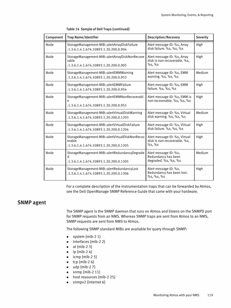
System Monitoring, Events, & Reporting
For a complete description of the instrumentation traps that can be forwarded by Atmos, see the Dell OpenManage SNMP Reference Guide that came with your hardware.
SNMP agent
The SNMP agent is the SNMP daemon that runs on Atmos and listens on the SNMPD port for SNMP requests from an NMS. Whereas SNMP traps are sent from Atmos to an NMS, SNMP requests are sent from NMS to Atmos.
The following SNMP standard MIBs are available for query through SNMP:
◆ system {mib-2 1}◆ interfaces {mib-2 2}◆ at {mib-2 3}◆ ip {mib-2 4}◆ icmp {mib-2 5}◆ tcp {mib-2 6}◆ udp {mib-2 7}◆ snmp {mib-2 11}◆ host resources {mib-2 25}◆ snmpv2 {internet 6}
Node StorageManagement-MIB::alertArrayDiskFailure.1.3.6.1.4.1.674.10893.1.20.200.0.904
Alert message ID: %s, Array disk failure. %s, %s, %s
High
Node StorageManagement-MIB::alertArrayDiskNonRecoverable.1.3.6.1.4.1.674.10893.1.20.200.0.905
Alert message ID: %s, Array disk is non-recoverable. %s, %s, %s
High
Node StorageManagement-MIB::alertEMMWarning.1.3.6.1.4.1.674.10893.1.20.200.0.953
Alert message ID: %s, EMM warning. %s, %s, %s
Medium
Node StorageManagement-MIB::alertEMMFailure.1.3.6.1.4.1.674.10893.1.20.200.0.954
Alert message ID: %s, EMM failure. %s, %s, %s
High
Node StorageManagement-MIB::alertEMMNonRecoverable.1.3.6.1.4.1.674.10893.1.20.200.0.955
Alert message ID: %s, EMM is non-recoverable. %s, %s, %s
High
Node StorageManagement-MIB::alertVirtualDiskWarning.1.3.6.1.4.1.674.10893.1.20.200.0.1203
Alert message ID: %s, Virtual disk warning. %s, %s, %s
Medium
Node StorageManagement-MIB::alertVirtualDiskFailure.1.3.6.1.4.1.674.10893.1.20.200.0.1204
Alert message ID: %s, Virtual disk failure. %s, %s, %s
High
Node StorageManagement-MIB::alertVirtualDiskNonRecoverable.1.3.6.1.4.1.674.10893.1.20.200.0.1205
Alert message ID: %s, Virtual disk is non-recoverable. %s, %s, %s
High
Node StorageManagement-MIB::alertRedundancyDegraded.1.3.6.1.4.1.674.10893.1.20.200.0.1305
Alert message ID: %s, Redundancy has been degraded. %s, %s, %s
Medium
Node StorageManagement-MIB::alertRedundancyLost.1.3.6.1.4.1.674.10893.1.20.200.0.1306
Alert message ID: %s, Redundancy has been lost. %s, %s, %s
High
Table 14 Sample of Dell Traps (continued)
Component Trap Name/Identifier Description/Recovery Severity
Monitoring Atmos with your NMS 119
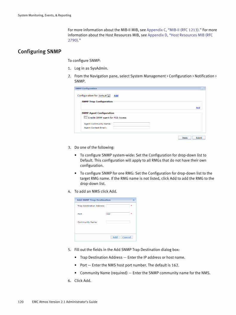
System Monitoring, Events, & Reporting
For more information about the MIB-II MIB, see Appendix C, “MIB-II (RFC 1213).” For more information about the Host Resources MIB, see Appendix D, “Host Resources MIB (RFC 2790).”
Configuring SNMP
To configure SNMP:
1. Log in as SysAdmin.
2. From the Navigation pane, select System Management > Configuration > Notification > SNMP.
3. Do one of the following:
• To configure SNMP system-wide: Set the Configuration for drop-down list to Default. This configuration will apply to all RMGs that do not have their own configuration.
• To configure SNMP for one RMG: Set the Configuration for drop-down list to the target RMG name. If the RMG name is not listed, click Add to add the RMG to the drop-down list.
4. To add an NMS click Add.
5. Fill out the fields in the Add SNMP Trap Destination dialog box:
• Trap Destination Address — Enter the IP address or host name.
• Port — Enter the NMS host port number. The default is 162.
• Community Name (required) — Enter the SNMP community name for the NMS.
6. Click Add.
120 EMC Atmos Version 2.1 Administrator’s Guide
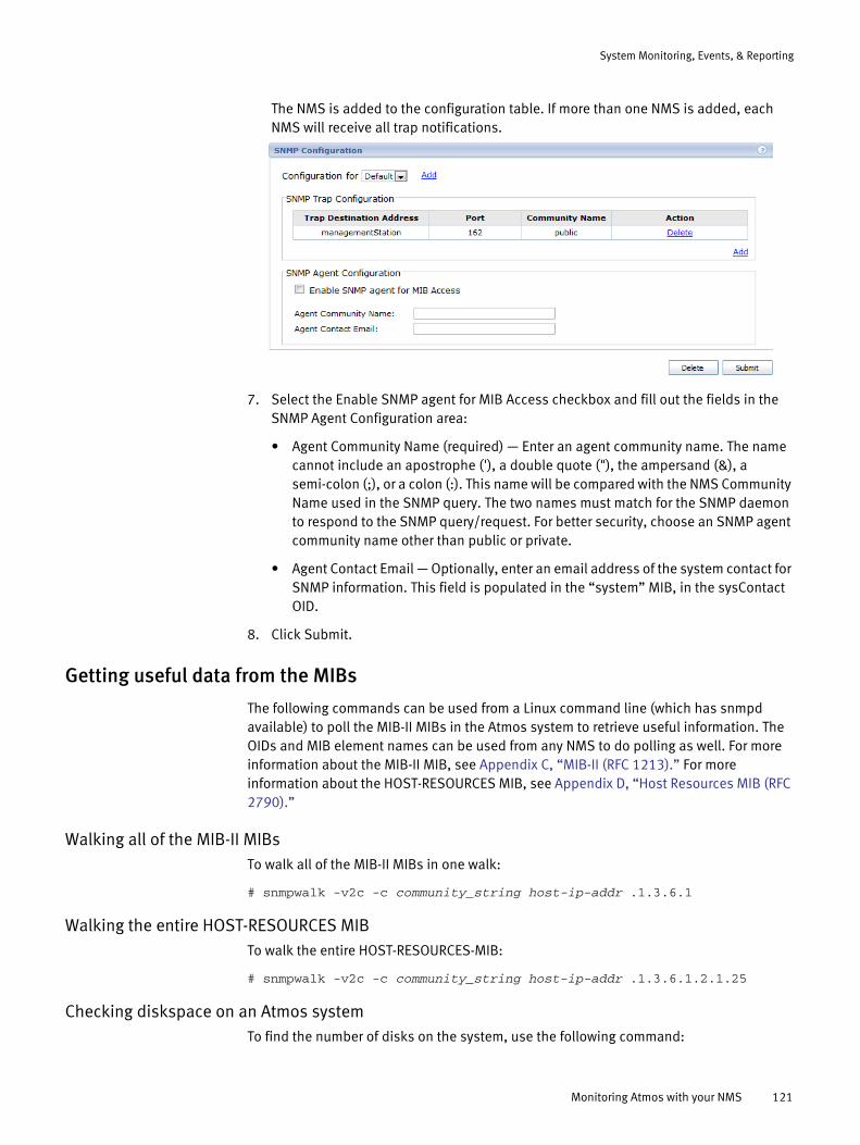
System Monitoring, Events, & Reporting
The NMS is added to the configuration table. If more than one NMS is added, each NMS will receive all trap notifications.
7. Select the Enable SNMP agent for MIB Access checkbox and fill out the fields in the SNMP Agent Configuration area:
• Agent Community Name (required) — Enter an agent community name. The name cannot include an apostrophe ('), a double quote ("), the ampersand (&), a semi-colon (;), or a colon (:). This name will be compared with the NMS Community Name used in the SNMP query. The two names must match for the SNMP daemon to respond to the SNMP query/request. For better security, choose an SNMP agent community name other than public or private.
• Agent Contact Email — Optionally, enter an email address of the system contact for SNMP information. This field is populated in the “system” MIB, in the sysContact OID.
8. Click Submit.
Getting useful data from the MIBs
The following commands can be used from a Linux command line (which has snmpd available) to poll the MIB-II MIBs in the Atmos system to retrieve useful information. The OIDs and MIB element names can be used from any NMS to do polling as well. For more information about the MIB-II MIB, see Appendix C, “MIB-II (RFC 1213).” For more information about the HOST-RESOURCES MIB, see Appendix D, “Host Resources MIB (RFC 2790).”
Walking all of the MIB-II MIBsTo walk all of the MIB-II MIBs in one walk:
# snmpwalk -v2c -c community_string host-ip-addr .1.3.6.1
Walking the entire HOST-RESOURCES MIBTo walk the entire HOST-RESOURCES-MIB:
# snmpwalk -v2c -c community_string host-ip-addr .1.3.6.1.2.1.25
Checking diskspace on an Atmos systemTo find the number of disks on the system, use the following command:
Monitoring Atmos with your NMS 121

System Monitoring, Events, & Reporting
# snmpwalk -v2c -c community_string host-ip-addrHOST-RESOURCES-MIB::hrStorageIndex
This command returns a table of hrStorageIndex items, each representing a disk. The disk is referenced by the index number. For example:
HOST-RESOURCES-MIB::hrStorageIndex.1 = INTEGER: 1HOST-RESOURCES-MIB::hrStorageIndex.3 = INTEGER: 3HOST-RESOURCES-MIB::hrStorageIndex.6 = INTEGER: 6HOST-RESOURCES-MIB::hrStorageIndex.7 = INTEGER: 7HOST-RESOURCES-MIB::hrStorageIndex.8 = INTEGER: 8HOST-RESOURCES-MIB::hrStorageIndex.10 = INTEGER: 10HOST-RESOURCES-MIB::hrStorageIndex.31 = INTEGER: 31HOST-RESOURCES-MIB::hrStorageIndex.32 = INTEGER: 32HOST-RESOURCES-MIB::hrStorageIndex.33 = INTEGER: 33HOST-RESOURCES-MIB::hrStorageIndex.34 = INTEGER: 34HOST-RESOURCES-MIB::hrStorageIndex.35 = INTEGER: 35...HOST-RESOURCES-MIB::hrStorageIndex.87 = INTEGER: 87HOST-RESOURCES-MIB::hrStorageIndex.88 = INTEGER: 88HOST-RESOURCES-MIB::hrStorageIndex.89 = INTEGER: 89
Finding disksTo find which disk is which, use the following command:
# snmpwalk -v2c -c community_string node-ip-addrHOST-RESOURCES-MIB::hrStorageDescr
This command lists the name of each disk, indexed by same index number as shown above. For example:
HOST-RESOURCES-MIB::hrStorageDescr.1 = STRING: Physical memoryHOST-RESOURCES-MIB::hrStorageDescr.3 = STRING: Virtual memoryHOST-RESOURCES-MIB::hrStorageDescr.6 = STRING: Memory buffersHOST-RESOURCES-MIB::hrStorageDescr.7 = STRING: Cached memoryHOST-RESOURCES-MIB::hrStorageDescr.8 = STRING: Shared memoryHOST-RESOURCES-MIB::hrStorageDescr.10 = STRING: Swap spaceHOST-RESOURCES-MIB::hrStorageDescr.31 = STRING: /HOST-RESOURCES-MIB::hrStorageDescr.32 = STRING: /bootHOST-RESOURCES-MIB::hrStorageDescr.33 = STRING:
/mauimds-db/mds-b2abb3f4-2584-437e-ac9c-03eecbd09b0eHOST-RESOURCES-MIB::hrStorageDescr.34 = STRING:
/mauimds-db/mds-a80a27a5-7e8f-4627-8a1f-c6780f0971a3HOST-RESOURCES-MIB::hrStorageDescr.35 = STRING:
/mauimds-db/mds-125c7b2a-6425-4003-9e12-7b929742fb4e...HOST-RESOURCES-MIB::hrStorageDescr.87 = STRING:
/mauiss-disks/ss-cc722b09-441b-4823-bc55-5e0aa4073e61HOST-RESOURCES-MIB::hrStorageDescr.88 = STRING:
/mauiss-disks/ss-18ae1f82-3186-4504-8b25-f681f8174520HOST-RESOURCES-MIB::hrStorageDescr.89 = STRING: /mnt/mauifs
Accessing individual disksTo access an individual disk by index, use the following command:
# snmpget -v2c -c community_string node-ip-addrHOST-RESOURCES-MIB::hrStorageDescr.node_index
This command returns the individual disk. For example:
HOST-RESOURCES-MIB::hrStorageDescr.89 = STRING: /mnt/mauifs
122 EMC Atmos Version 2.1 Administrator’s Guide
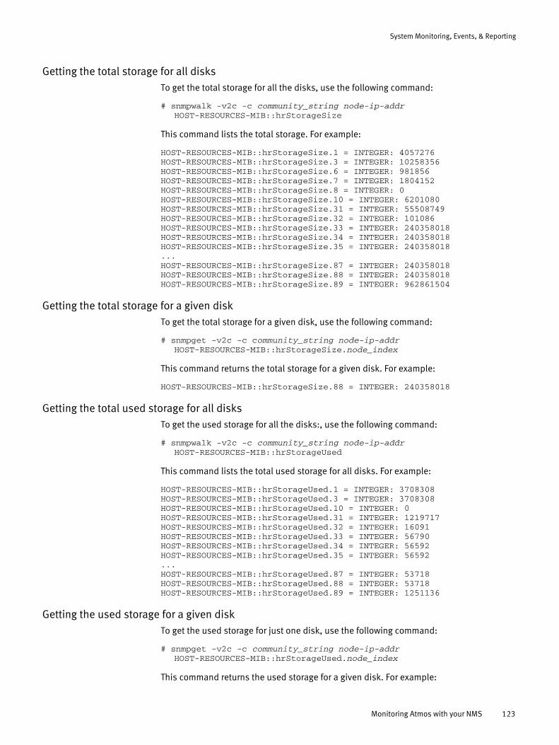
System Monitoring, Events, & Reporting
Getting the total storage for all disksTo get the total storage for all the disks, use the following command:
# snmpwalk -v2c -c community_string node-ip-addrHOST-RESOURCES-MIB::hrStorageSize
This command lists the total storage. For example:
HOST-RESOURCES-MIB::hrStorageSize.1 = INTEGER: 4057276HOST-RESOURCES-MIB::hrStorageSize.3 = INTEGER: 10258356HOST-RESOURCES-MIB::hrStorageSize.6 = INTEGER: 981856HOST-RESOURCES-MIB::hrStorageSize.7 = INTEGER: 1804152HOST-RESOURCES-MIB::hrStorageSize.8 = INTEGER: 0HOST-RESOURCES-MIB::hrStorageSize.10 = INTEGER: 6201080HOST-RESOURCES-MIB::hrStorageSize.31 = INTEGER: 55508749HOST-RESOURCES-MIB::hrStorageSize.32 = INTEGER: 101086HOST-RESOURCES-MIB::hrStorageSize.33 = INTEGER: 240358018HOST-RESOURCES-MIB::hrStorageSize.34 = INTEGER: 240358018HOST-RESOURCES-MIB::hrStorageSize.35 = INTEGER: 240358018...HOST-RESOURCES-MIB::hrStorageSize.87 = INTEGER: 240358018HOST-RESOURCES-MIB::hrStorageSize.88 = INTEGER: 240358018HOST-RESOURCES-MIB::hrStorageSize.89 = INTEGER: 962861504
Getting the total storage for a given diskTo get the total storage for a given disk, use the following command:
# snmpget -v2c -c community_string node-ip-addrHOST-RESOURCES-MIB::hrStorageSize.node_index
This command returns the total storage for a given disk. For example:
HOST-RESOURCES-MIB::hrStorageSize.88 = INTEGER: 240358018
Getting the total used storage for all disksTo get the used storage for all the disks:, use the following command:
# snmpwalk -v2c -c community_string node-ip-addrHOST-RESOURCES-MIB::hrStorageUsed
This command lists the total used storage for all disks. For example:
HOST-RESOURCES-MIB::hrStorageUsed.1 = INTEGER: 3708308HOST-RESOURCES-MIB::hrStorageUsed.3 = INTEGER: 3708308HOST-RESOURCES-MIB::hrStorageUsed.10 = INTEGER: 0HOST-RESOURCES-MIB::hrStorageUsed.31 = INTEGER: 1219717HOST-RESOURCES-MIB::hrStorageUsed.32 = INTEGER: 16091HOST-RESOURCES-MIB::hrStorageUsed.33 = INTEGER: 56790HOST-RESOURCES-MIB::hrStorageUsed.34 = INTEGER: 56592HOST-RESOURCES-MIB::hrStorageUsed.35 = INTEGER: 56592...HOST-RESOURCES-MIB::hrStorageUsed.87 = INTEGER: 53718HOST-RESOURCES-MIB::hrStorageUsed.88 = INTEGER: 53718HOST-RESOURCES-MIB::hrStorageUsed.89 = INTEGER: 1251136
Getting the used storage for a given diskTo get the used storage for just one disk, use the following command:
# snmpget -v2c -c community_string node-ip-addrHOST-RESOURCES-MIB::hrStorageUsed.node_index
This command returns the used storage for a given disk. For example:
Monitoring Atmos with your NMS 123

System Monitoring, Events, & Reporting
HOST-RESOURCES-MIB::hrStorageUsed.88 = 53718
Calculating the total free disk spaceTo calculate the total free disk space, subtract hrStorageUsed from hrStorageSize.
Getting the system uptimeTo get the amount of time since this host was last initialized, use the following command:
# snmpget -v2c -c community_string node-ip-addrHOST-RESOURCES-MIB::hrSystemUptime.node_index
This command returns the system uptime. For example:
HOST-RESOURCES-MIB::hrSystemUptime.0 = Timeticks: (196243987) 22 days,17:07:19.87
Getting the number of system usersTo get the number of user sessions for which this host is storing state information, use the following command:
# snmpget -v2c -c community_string node-ip-addrHOST-RESOURCES-MIB::hrSystemNumUsers.node_index
This command returns the number of users. For example:
HOST-RESOURCES-MIB::hrSystemNumUsers.0 = Gauge32: 2
Getting the number of system processesTo get the number of processes currently running on a system, use the following command:
# snmpget -v2c -c community_string node-ip-addrHOST-RESOURCES-MIB::hrSystemProcesses.node_index
This command returns the number of processes. For example:
HOST-RESOURCES-MIB::hrSystemProcesses.0 = Gauge32: 318
Getting the maximum number of system processesTo get the maximum number of processes the system can support, use the following command:
# snmpget -v2c -c community_string node-ip-addrHOST-RESOURCES-MIB::hrSystemMaxProcesses.node_index
This command returns the maximum number of processes that the system can support. A value of zero represents that there is no fixed maximum value. For example:
HOST-RESOURCES-MIB::hrSystemMaxProcesses.0 = INTEGER: 0
Getting the memory sizeTo get the size of the memory, use the following command:
# snmpget -v2c -c community_string node-ip-addrHOST-RESOURCES-MIB::hrMemorySize.node_index
This command returns the memory size. For example:
HOST-RESOURCES-MIB::hrMemorySize.0 = INTEGER: 4057276 KBytes
124 EMC Atmos Version 2.1 Administrator’s Guide
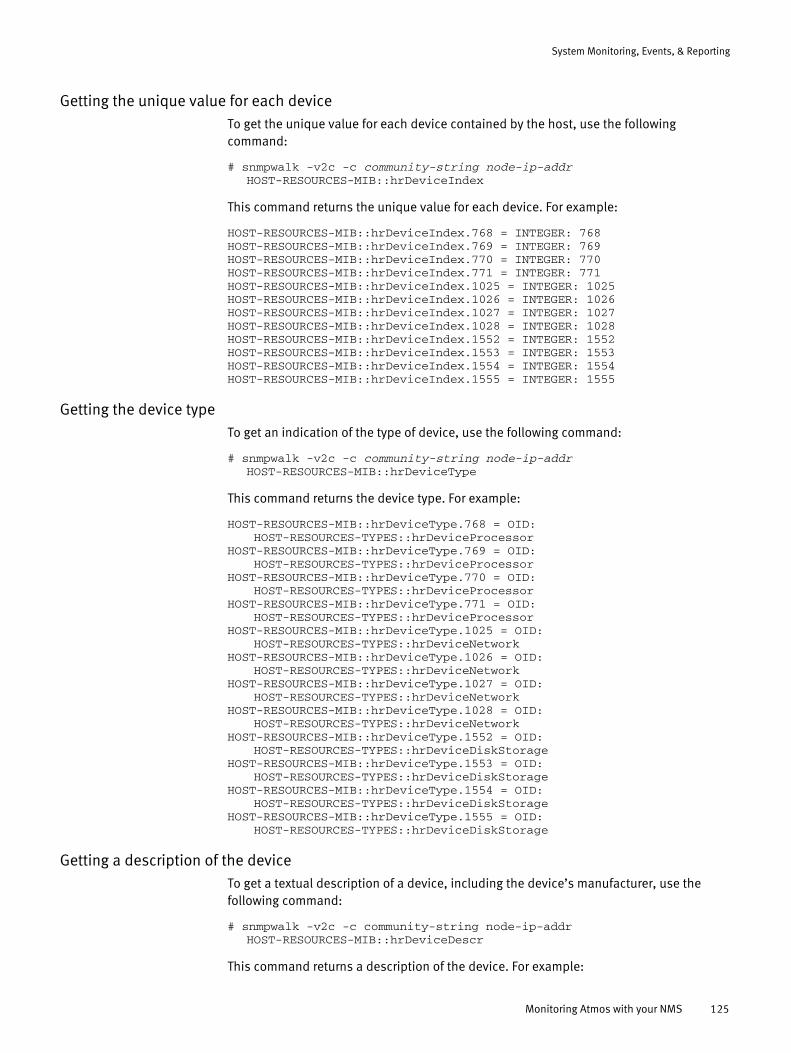
System Monitoring, Events, & Reporting
Getting the unique value for each deviceTo get the unique value for each device contained by the host, use the following command:
# snmpwalk -v2c -c community-string node-ip-addrHOST-RESOURCES-MIB::hrDeviceIndex
This command returns the unique value for each device. For example:
HOST-RESOURCES-MIB::hrDeviceIndex.768 = INTEGER: 768HOST-RESOURCES-MIB::hrDeviceIndex.769 = INTEGER: 769HOST-RESOURCES-MIB::hrDeviceIndex.770 = INTEGER: 770HOST-RESOURCES-MIB::hrDeviceIndex.771 = INTEGER: 771HOST-RESOURCES-MIB::hrDeviceIndex.1025 = INTEGER: 1025HOST-RESOURCES-MIB::hrDeviceIndex.1026 = INTEGER: 1026HOST-RESOURCES-MIB::hrDeviceIndex.1027 = INTEGER: 1027HOST-RESOURCES-MIB::hrDeviceIndex.1028 = INTEGER: 1028HOST-RESOURCES-MIB::hrDeviceIndex.1552 = INTEGER: 1552HOST-RESOURCES-MIB::hrDeviceIndex.1553 = INTEGER: 1553HOST-RESOURCES-MIB::hrDeviceIndex.1554 = INTEGER: 1554HOST-RESOURCES-MIB::hrDeviceIndex.1555 = INTEGER: 1555
Getting the device typeTo get an indication of the type of device, use the following command:
# snmpwalk -v2c -c community-string node-ip-addrHOST-RESOURCES-MIB::hrDeviceType
This command returns the device type. For example:
HOST-RESOURCES-MIB::hrDeviceType.768 = OID:HOST-RESOURCES-TYPES::hrDeviceProcessor
HOST-RESOURCES-MIB::hrDeviceType.769 = OID:HOST-RESOURCES-TYPES::hrDeviceProcessor
HOST-RESOURCES-MIB::hrDeviceType.770 = OID:HOST-RESOURCES-TYPES::hrDeviceProcessor
HOST-RESOURCES-MIB::hrDeviceType.771 = OID:HOST-RESOURCES-TYPES::hrDeviceProcessor
HOST-RESOURCES-MIB::hrDeviceType.1025 = OID:HOST-RESOURCES-TYPES::hrDeviceNetwork
HOST-RESOURCES-MIB::hrDeviceType.1026 = OID:HOST-RESOURCES-TYPES::hrDeviceNetwork
HOST-RESOURCES-MIB::hrDeviceType.1027 = OID:HOST-RESOURCES-TYPES::hrDeviceNetwork
HOST-RESOURCES-MIB::hrDeviceType.1028 = OID:HOST-RESOURCES-TYPES::hrDeviceNetwork
HOST-RESOURCES-MIB::hrDeviceType.1552 = OID:HOST-RESOURCES-TYPES::hrDeviceDiskStorage
HOST-RESOURCES-MIB::hrDeviceType.1553 = OID:HOST-RESOURCES-TYPES::hrDeviceDiskStorage
HOST-RESOURCES-MIB::hrDeviceType.1554 = OID:HOST-RESOURCES-TYPES::hrDeviceDiskStorage
HOST-RESOURCES-MIB::hrDeviceType.1555 = OID:HOST-RESOURCES-TYPES::hrDeviceDiskStorage
Getting a description of the deviceTo get a textual description of a device, including the device’s manufacturer, use the following command:
# snmpwalk -v2c -c community-string node-ip-addrHOST-RESOURCES-MIB::hrDeviceDescr
This command returns a description of the device. For example:
Monitoring Atmos with your NMS 125

System Monitoring, Events, & Reporting
HOST-RESOURCES-MIB::hrDeviceDescr.768 = STRING: GenuineIntel:Intel(R) Xeon(R) CPU E5410 @ 2.33GHz
HOST-RESOURCES-MIB::hrDeviceDescr.769 = STRING: GenuineIntel:Intel(R) Xeon(R) CPU E5410 @ 2.33GHz
HOST-RESOURCES-MIB::hrDeviceDescr.770 = STRING: GenuineIntel:Intel(R) Xeon(R) CPU E5410 @ 2.33GHz
HOST-RESOURCES-MIB::hrDeviceDescr.771 = STRING: GenuineIntel:Intel(R) Xeon(R) CPU E5410 @ 2.33GHz
HOST-RESOURCES-MIB::hrDeviceDescr.1025 = STRING: network interface loHOST-RESOURCES-MIB::hrDeviceDescr.1026 = STRING: network interface
eth0HOST-RESOURCES-MIB::hrDeviceDescr.1027 = STRING: network interface
eth1HOST-RESOURCES-MIB::hrDeviceDescr.1028 = STRING: network interface
sit0HOST-RESOURCES-MIB::hrDeviceDescr.1552 = STRING: SCSI disk (/dev/sda)HOST-RESOURCES-MIB::hrDeviceDescr.1553 = STRING: SCSI disk (/dev/sdb)HOST-RESOURCES-MIB::hrDeviceDescr.1554 = STRING: SCSI disk (/dev/sdc)HOST-RESOURCES-MIB::hrDeviceDescr.1555 = STRING: SCSI disk (/dev/sdd)
Getting the average processor loadTo get the average load (over the last minute) for each processor, use the following command:
# snmpwalk -v2c -c community-string node-ip-addrHOST-RESOURCES-MIB::hrProcessorLoad
This command returns the processor loads. For example:
HOST-RESOURCES-MIB::hrProcessorLoad.768 = INTEGER: 11HOST-RESOURCES-MIB::hrProcessorLoad.769 = INTEGER: 13HOST-RESOURCES-MIB::hrProcessorLoad.770 = INTEGER: 19HOST-RESOURCES-MIB::hrProcessorLoad.771 = INTEGER: 15
Walking all of the Interfaces MIBTo walk all of the interfaces MIB in one walk, use the following command:
# snmpwalk -v2c -c community_string node-ip-addr .1.3.6.1.2.1.2.2.1
Getting the unique value for each network interfaceTo get the unique value for each interface, use the following command:
# snmpwalk -v2c community_string node-ip-addr IF-MIB::ifIndex
This command returns the unique values for each interface. For example:
IF-MIB::ifIndex.1 = INTEGER: 1IF-MIB::ifIndex.2 = INTEGER: 2IF-MIB::ifIndex.3 = INTEGER: 3IF-MIB::ifIndex.4 = INTEGER: 4
Getting information about an interfaceTo get a textual string containing information about the interface, use the following command:
# snmpwalk -v2c community_string node-ip-addr IF-MIB::ifDescr
This command returns information about the interface. For example:
IF-MIB::ifDescr.1 = STRING: loIF-MIB::ifDescr.2 = STRING: eth0IF-MIB::ifDescr.3 = STRING: eth1
126 EMC Atmos Version 2.1 Administrator’s Guide
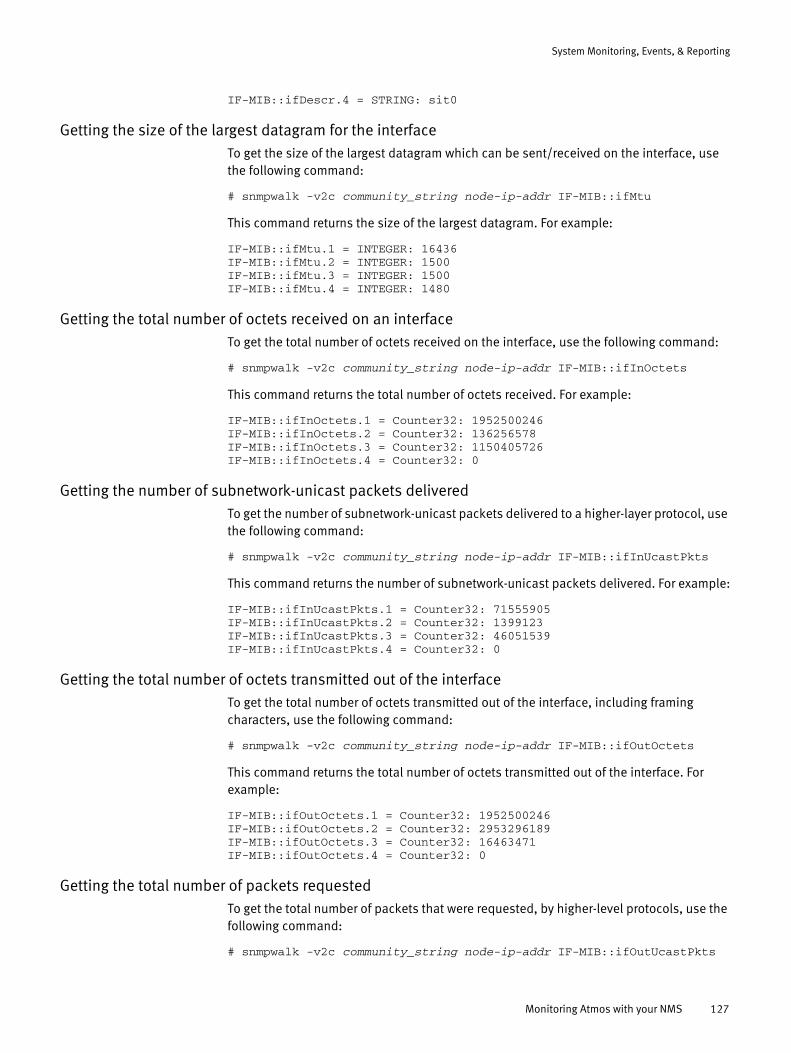
System Monitoring, Events, & Reporting
IF-MIB::ifDescr.4 = STRING: sit0
Getting the size of the largest datagram for the interfaceTo get the size of the largest datagram which can be sent/received on the interface, use the following command:
# snmpwalk -v2c community_string node-ip-addr IF-MIB::ifMtu
This command returns the size of the largest datagram. For example:
IF-MIB::ifMtu.1 = INTEGER: 16436IF-MIB::ifMtu.2 = INTEGER: 1500IF-MIB::ifMtu.3 = INTEGER: 1500IF-MIB::ifMtu.4 = INTEGER: 1480
Getting the total number of octets received on an interfaceTo get the total number of octets received on the interface, use the following command:
# snmpwalk -v2c community_string node-ip-addr IF-MIB::ifInOctets
This command returns the total number of octets received. For example:
IF-MIB::ifInOctets.1 = Counter32: 1952500246IF-MIB::ifInOctets.2 = Counter32: 136256578IF-MIB::ifInOctets.3 = Counter32: 1150405726IF-MIB::ifInOctets.4 = Counter32: 0
Getting the number of subnetwork-unicast packets deliveredTo get the number of subnetwork-unicast packets delivered to a higher-layer protocol, use the following command:
# snmpwalk -v2c community_string node-ip-addr IF-MIB::ifInUcastPkts
This command returns the number of subnetwork-unicast packets delivered. For example:
IF-MIB::ifInUcastPkts.1 = Counter32: 71555905IF-MIB::ifInUcastPkts.2 = Counter32: 1399123IF-MIB::ifInUcastPkts.3 = Counter32: 46051539IF-MIB::ifInUcastPkts.4 = Counter32: 0
Getting the total number of octets transmitted out of the interfaceTo get the total number of octets transmitted out of the interface, including framing characters, use the following command:
# snmpwalk -v2c community_string node-ip-addr IF-MIB::ifOutOctets
This command returns the total number of octets transmitted out of the interface. For example:
IF-MIB::ifOutOctets.1 = Counter32: 1952500246IF-MIB::ifOutOctets.2 = Counter32: 2953296189IF-MIB::ifOutOctets.3 = Counter32: 16463471IF-MIB::ifOutOctets.4 = Counter32: 0
Getting the total number of packets requestedTo get the total number of packets that were requested, by higher-level protocols, use the following command:
# snmpwalk -v2c community_string node-ip-addr IF-MIB::ifOutUcastPkts
Monitoring Atmos with your NMS 127

System Monitoring, Events, & Reporting
This command returns the total number of packets that were requested. For example:
IF-MIB::ifOutUcastPkts.1 = Counter32: 71555905IF-MIB::ifOutUcastPkts.2 = Counter32: 2025319IF-MIB::ifOutUcastPkts.3 = Counter32: 22655375IF-MIB::ifOutUcastPkts.4 = Counter32: 0
Getting the state of a node’s network interfaces using snmpnetstatTo get the state of a node’s network interface, use the following Linux command:
# snmpnetstat -v2c -c community_string -i node-ip-addr
This command returns the state of the network interfaces.
System reportsAtmos can collect system configuration data and node-level events to send in a System Report to the EMC System Reports database through the System Report (SYR) mechanism. System reports are sent to the EMC System Reports Database to improve customer service, and allow EMC to provide timely support for Atmos issues.
Configuring system reports
The System Report Configuration page is used to configure Atmos to be able to securely send Atmos configuration information and error event information to EMC support personnel. The configuration data allows EMC to analyze detailed information about your Atmos environment, including: system information, RMG information, and tenant information.
An SMTP connection is used to send the configuration information. Once the configuration information is received, it is analyzed by a service automation tool called SYR. SYR serves as a repository for configuration data and is used to provide faster problem resolution. The error event information allows EMC Customer Support to handle error events on your Atmos system in a timely manner.
Before using system report configuration, you must provide a system master serial number at installation time, or input it from the Navigation pane by clicking Configuration > System Master Serial Number.
The procedure in this section configures Atmos for system reporting. To actually collect the data, see “Collecting system reports.”
To configure system reports:
1. Log in as SysAdmin.
2. From the Navigation pane, click Configuration > System Report to display the System Report Configuration page.
If you have not already configured the system master serial number, a warning message appears on the page and you cannot configure system reporting.
128 EMC Atmos Version 2.1 Administrator’s Guide
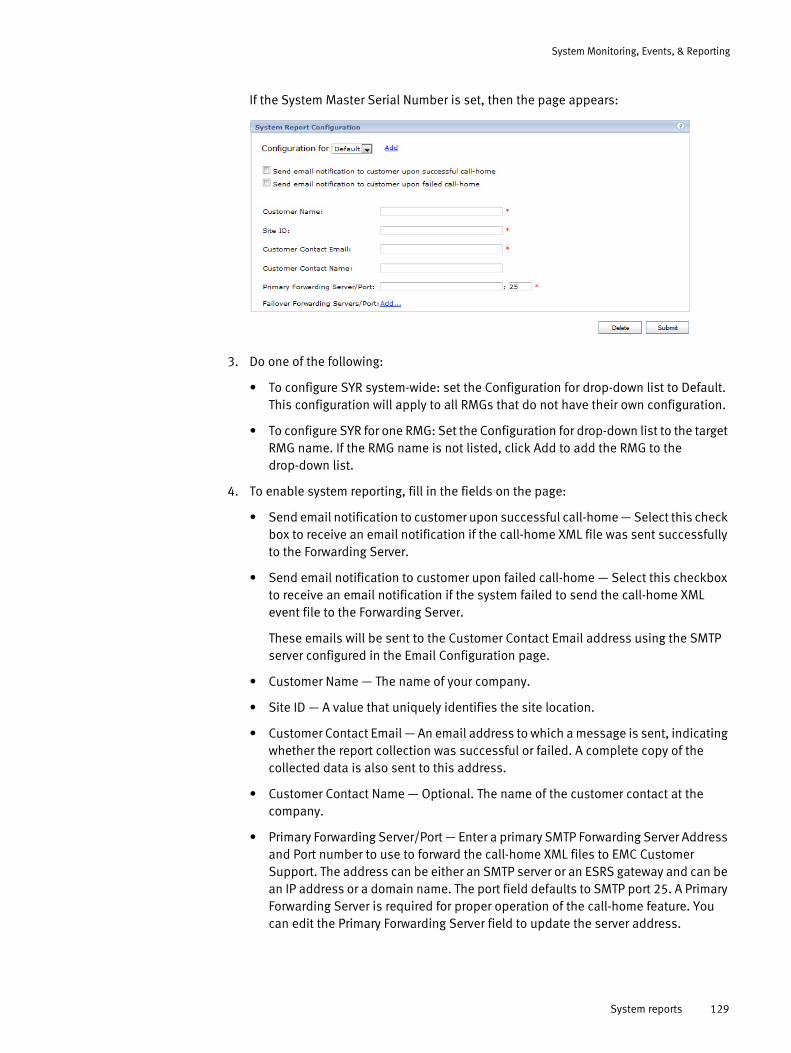
System Monitoring, Events, & Reporting
If the System Master Serial Number is set, then the page appears:
3. Do one of the following:
• To configure SYR system-wide: set the Configuration for drop-down list to Default. This configuration will apply to all RMGs that do not have their own configuration.
• To configure SYR for one RMG: Set the Configuration for drop-down list to the target RMG name. If the RMG name is not listed, click Add to add the RMG to the drop-down list.
4. To enable system reporting, fill in the fields on the page:
• Send email notification to customer upon successful call-home — Select this check box to receive an email notification if the call-home XML file was sent successfully to the Forwarding Server.
• Send email notification to customer upon failed call-home — Select this checkbox to receive an email notification if the system failed to send the call-home XML event file to the Forwarding Server.
These emails will be sent to the Customer Contact Email address using the SMTP server configured in the Email Configuration page.
• Customer Name — The name of your company.
• Site ID — A value that uniquely identifies the site location.
• Customer Contact Email — An email address to which a message is sent, indicating whether the report collection was successful or failed. A complete copy of the collected data is also sent to this address.
• Customer Contact Name — Optional. The name of the customer contact at the company.
• Primary Forwarding Server/Port — Enter a primary SMTP Forwarding Server Address and Port number to use to forward the call-home XML files to EMC Customer Support. The address can be either an SMTP server or an ESRS gateway and can be an IP address or a domain name. The port field defaults to SMTP port 25. A Primary Forwarding Server is required for proper operation of the call-home feature. You can edit the Primary Forwarding Server field to update the server address.
System reports 129

System Monitoring, Events, & Reporting
• Failover Forwarding Servers/Port — Optional. Click Add and enter a failover SMTP Forwarding Server Address and Port number. If you are using SMTP servers as your forwarding servers and have different SMTP servers configured for different RMGs in the system, add a failover forwarding server for each SMTP server.
The call-home feature will try to send the call-home XML file through the Primary Forwarding Server and then any failover forwarding servers until the file is successfully sent to a forwarding server or the list of servers is exhausted.
To remove any of the Failover Forwarding Servers, click the X to remove the server from the list.
5. Click Submit.
SYR symptom codes
Atmos sends symptom codes of detected problems to the EMC System Reports database through the System Report (SYR) mechanism.
Table 15lists the Atmos events wit SYR symptom codes.
Table 15 Atmos Events with SYR Symptom Codes
Event ID OID
SYR Code Category Event Name Event Message Description
110 .1.3.6.1.4.1.1139.16.3.1000.130
110 Configuration UI_CHG_NODE_IP_FAILED_EVT
User %s failed to change the IP address for the node. Reason: %s
This is a configuration event.
1004 .1.3.6.1.4.1.1139.16.3.1000.146
1004 Configuration SM_MM_SETAUTOFAILOVER_FAIL_EVT
Failed to set autofailover. Reason: %s
This is a configuration event.
20002 .1.3.6.1.4.1.1139.16.3.1000.137
20002 Upgrade SM_UPGRADE_FAIL_EVT
Upgrade to software version %s failed on node %s.
This is an upgrade event.
20007 .1.3.6.1.4.1.1139.16.3.1000.137
20007 Upgrade SM_PREPARE_FAIL_EVT
Upgrade prepare step for version %s failed on node %s.
This is an upgrade event.
20008 .1.3.6.1.4.1.1139.16.3.1000.195
20008 Upgrade MDS_CONVERSION_PAUSED
MDS %s CC or BDB conversion task has been paused. Insufficient disk space to continue.
MDS conversion paused.
30001 .1.3.6.1.4.1.1139.16.3.1000.138
30001 Installation SM_UPDATE_FAIL_EVT Installation of service pack/hotfix %d failed.
This is an installation event.
31002 .1.3.6.1.4.1.1139.16.3.1000.168
31002 Configuration MDS_ERROR_CREATING_MDS_SET_CONFIG
Error creating MDS set configuration.
This is a configuration event.
31003 .1.3.6.1.4.1.1139.16.3.1000.169
31003 Configuration MDS_ERROR_INSUFFICIENT_MDS_DISK
Unable to configure MDS sets. Insufficient number of metadata disks found.
This is a configuration event.
130 EMC Atmos Version 2.1 Administrator’s Guide

System Monitoring, Events, & Reporting
40000 .1.3.6.1.4.1.1139.16.3.1000.155
40000 Disk DM_FAILED_PARTITION_EVT
Failed to partition disk %s in slot %s. This disk will be placed in the DISK_STATUS_CRITICAL state and will not be used.
This is a disk event.
40001 .1.3.6.1.4.1.1139.16.3.1000.155
40001 Disk DM_FAILED_FORMAT_EVT
Failed to format partition on disk %s in slot %s. This disk will be placed in the DISK_STATUS_CRITICAL state and will not be used.
This is a disk event.
40006 .1.3.6.1.4.1.1139.16.3.1000.156
40006 Disk DM_DISK_UNAVAILABLE
Disk %s with filesystem %s in DAE %s slot %s has become unavailable. The disk will be put into the DISK_STATUS_REMOVED state.
This is a disk event.
40007 .1.3.6.1.4.1.1139.16.3.1000.157
40007 Disk DM_DAE_UNAVAILABLE
DAE element %s has become unavailable.
This is a disk event.
40008 .1.3.6.1.4.1.1139.16.3.1000.158
40008 Disk DM_DISK_ERROR An error has occurred on filesystem %s on disk %s in DAE %s slot %s. The disk is being put into the DISK_STATUS_CRITICAL state.
This is a disk event.
40014 .1.3.6.1.4.1.1139.16.3.1000.143
40014 Disk DM_MOUNT_FAILED Failed to mount filesystem %s. Error details: %s
This is a disk event.
40018 .1.3.6.1.4.1.1139.16.3.1000.156
40018 Disk DM_UUIDS_NOT_FOUND
"Disk UUID's are not found on this machine. If this is a virtual machine, please add 'disk.enableUUID = TRUE' to the virtual machine settings. For more details, see the installation guide."
This is a disk event.
40022 .1.3.6.1.4.1.1139.16.3.1000.166
40022 Disk DM_FILESYSTEM_NOT_IN_USE
Filesystem is no longer being used by services. Filesystem: %s Disk: %s DAE %s slot %s
This is a disk event.
40023 .1.3.6.1.4.1.1139.16.3.1000.165
40023 Disk DM_DAE_ERROR Error detected on DAE %s. Error details: %s.
This is a disk event.
40028 .1.3.6.1.4.1.1139.16.3.1000.171
40028 Disk DM_SYSDISK_UTILIZATION_CRIT
Utilization for system disk partition %s has reached a critical level. Current utilization: %s
This is a disk event.
Table 15 Atmos Events with SYR Symptom Codes
Event ID OID
SYR Code Category Event Name Event Message Description
System reports 131
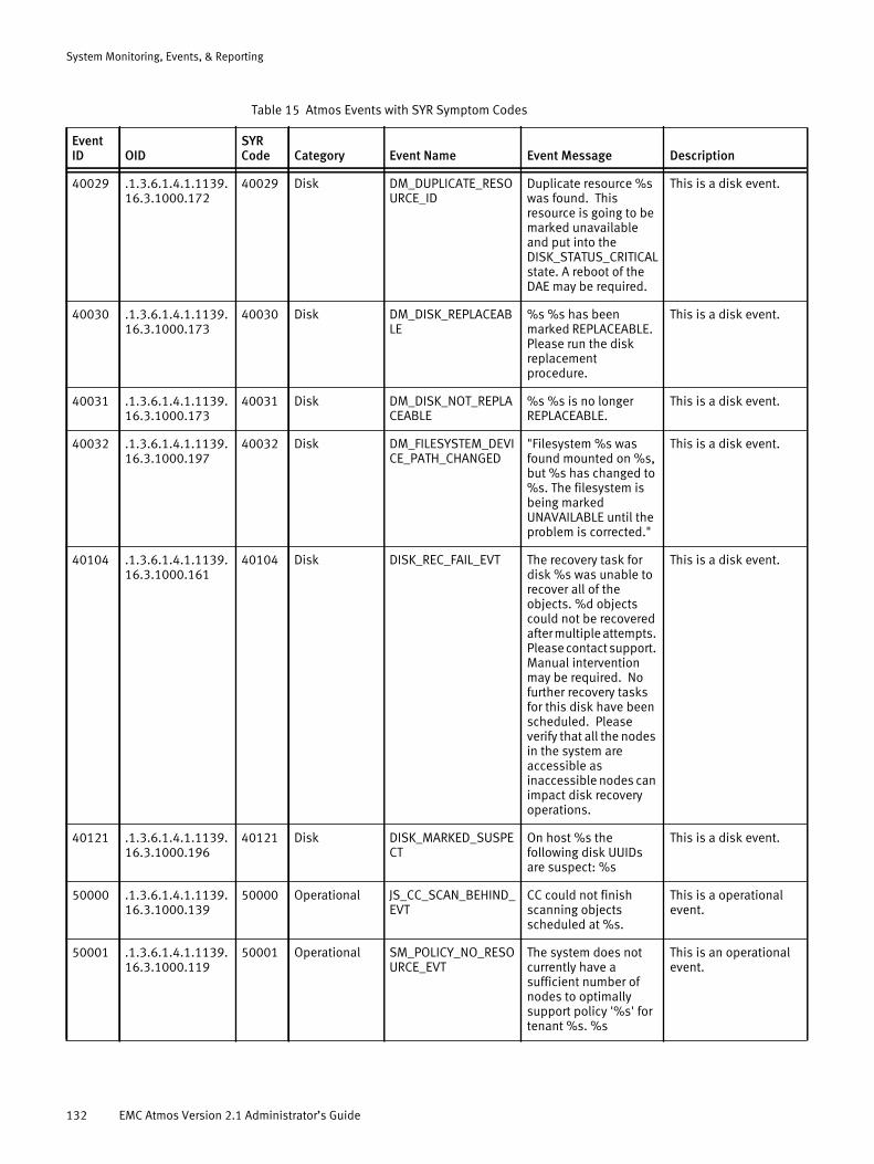
System Monitoring, Events, & Reporting
40029 .1.3.6.1.4.1.1139.16.3.1000.172
40029 Disk DM_DUPLICATE_RESOURCE_ID
Duplicate resource %s was found. This resource is going to be marked unavailable and put into the DISK_STATUS_CRITICAL state. A reboot of the DAE may be required.
This is a disk event.
40030 .1.3.6.1.4.1.1139.16.3.1000.173
40030 Disk DM_DISK_REPLACEABLE
%s %s has been marked REPLACEABLE. Please run the disk replacement procedure.
This is a disk event.
40031 .1.3.6.1.4.1.1139.16.3.1000.173
40031 Disk DM_DISK_NOT_REPLACEABLE
%s %s is no longer REPLACEABLE.
This is a disk event.
40032 .1.3.6.1.4.1.1139.16.3.1000.197
40032 Disk DM_FILESYSTEM_DEVICE_PATH_CHANGED
"Filesystem %s was found mounted on %s, but %s has changed to %s. The filesystem is being marked UNAVAILABLE until the problem is corrected."
This is a disk event.
40104 .1.3.6.1.4.1.1139.16.3.1000.161
40104 Disk DISK_REC_FAIL_EVT The recovery task for disk %s was unable to recover all of the objects. %d objects could not be recovered after multiple attempts. Please contact support. Manual intervention may be required. No further recovery tasks for this disk have been scheduled. Please verify that all the nodes in the system are accessible as inaccessible nodes can impact disk recovery operations.
This is a disk event.
40121 .1.3.6.1.4.1.1139.16.3.1000.196
40121 Disk DISK_MARKED_SUSPECT
On host %s the following disk UUIDs are suspect: %s
This is a disk event.
50000 .1.3.6.1.4.1.1139.16.3.1000.139
50000 Operational JS_CC_SCAN_BEHIND_EVT
CC could not finish scanning objects scheduled at %s.
This is a operational event.
50001 .1.3.6.1.4.1.1139.16.3.1000.119
50001 Operational SM_POLICY_NO_RESOURCE_EVT
The system does not currently have a sufficient number of nodes to optimally support policy '%s' for tenant %s. %s
This is an operational event.
Table 15 Atmos Events with SYR Symptom Codes
Event ID OID
SYR Code Category Event Name Event Message Description
132 EMC Atmos Version 2.1 Administrator’s Guide

System Monitoring, Events, & Reporting
50002 .1.3.6.1.4.1.1139.16.3.1000.145
50002 Operational SM_POLICY_GET_FAIL_EVT
Unable to verify system resources for storage policies - cannot communicate with the system database. Please check the network connection and health status of the master node.
This is an operational event.
50003 .1.3.6.1.4.1.1139.16.3.1000.126
50003 Operational MON_NTP_SYNC_ERR_EVT
NTP time difference between nodes is at the critical limit (4 minutes). Please resync the clock sources.
This is an operational event.
50005 .1.3.6.1.4.1.1139.16.3.1000.102
50005 Operational MON_MEM_USAGE_ERR_EVT
Memory Usage has exceeded threshold of %d.
This is an operational event.
50006 .1.3.6.1.4.1.1139.16.3.1000.101
50006 Operational MON_CPU_USAGE_ERR_EVT
CPU Usage has exceeded threshold of %d
This is an operational event.
50007 .1.3.6.1.4.1.1139.16.3.1000.139
50007 Operational JS_CC_NO_RESOURCE_EVT
The consistency checker has been unable to complete its desired object verifications for the past %d days.
This is an operational event.
50008 .1.3.6.1.4.1.1139.16.3.1000.124
50008 Operational MDS_SET_NO_ACCESS_EVT
MDS Set %s has no running MDS instances. MDS instances down: %s
This is an operational event.
50009 .1.3.6.1.4.1.1139.16.3.1000.124
50009 Operational MDS_SET_RO_EVT MDS Set %s has read-only access. MDS instances down: %s.
This is an operational event.
50010 .1.3.6.1.4.1.1139.16.3.1000.124
50010 Operational MDS_MULTIMASTER_EVT
MDS Set %s has multiple masters: %s
This is an operational event.
50011 .1.3.6.1.4.1.1139.16.3.1000.124
50011 Operational MDS_CFG_NO_FREE_PORT_EVT
MDS Set could not be created - reached max available ports.
This is an operational event.
50012 .1.3.6.1.4.1.1139.16.3.1000.124
50012 Operational MDS_CFG_NO_FREE_NODE_EVT
"MDS Set could not be created, no nodes are eligible for MDS instances"
This is an operational event.
50013 .1.3.6.1.4.1.1139.16.3.1000.127
50013 Operational MDS_CFG_INSTANCE_FAIL_EVT
Failed to configure MDS instance for port %d on node %s
This is an operational event.
Table 15 Atmos Events with SYR Symptom Codes
Event ID OID
SYR Code Category Event Name Event Message Description
System reports 133

System Monitoring, Events, & Reporting
50015 .1.3.6.1.4.1.1139.16.3.1000.123
50015 Operational MDS_EXCD_TENANT_THRSHD
The number of ILM and/or garbage collection jobs for MDS instance %s (tenant=%s) is %d and has exceeded the threshold of %d. This may indicate the system is under heavy load and is temporarily unable to keep up. If this event has been posted multiple times in one week, please contact support.
This is an operational event.
50016 .1.3.6.1.4.1.1139.16.3.1000.123
50016 Operational MDS_EXCD_MDS_THRSHD
The total number of ILM and/or garbage collection jobs for MDS instance %s is %d and has exceeded the threshold of %d. This may indicate the system is under heavy load and is temporarily unable to keep up. If this event has been posted multiple times in one week, please contact support.
This is an operational event.
50017 .1.3.6.1.4.1.1139.16.3.1000.135
50017 Operational MDS_CFG_FAIL_EVT Error while configuring MDS on node %s: %s.
This is an operational event.
50022 .1.3.6.1.4.1.1139.16.3.1000.140
50022 Operational CAS_MULTIPLE_RESTART_EVT
CAS service has been restarted %d times in last %d %s. An additional attempt to restart casd exceeds the threshold of %d times in %d %s.
This is an operational event.
50023 .1.3.6.1.4.1.1139.16.3.1000.141
50023 Operational CAS_LRG_BLOB_UNORPHAN_QUEUE_EVT
CAS blob unorphaning queue size (%d) exceeds the threshold (%d).
This is an operational event.
50024 .1.3.6.1.4.1.1139.16.3.1000.141
50024 Operational CAS_LRG_BLOB_DELETE_QUEUE_EVT
CAS blob delete queue size (%d) exceeds the threshold (%d).
This is an operational event.
50025 .1.3.6.1.4.1.1139.16.3.1000.141
50025 Operational CAS_LRG_MD_PROMO_QUEUE_EVT
CAS metadata promotion queue size (%d) exceeds the threshold (%d).
This is an operational event.
50026 .1.3.6.1.4.1.1139.16.3.1000.151
50026 Operational WS_HTTPD_WORKER_CRASH
An httpd worker has crashed %d times in the last %d %s. This exceeds the threshold of %d times in %d %s.
Apache httpd worker crash threshold reached.
Table 15 Atmos Events with SYR Symptom Codes
Event ID OID
SYR Code Category Event Name Event Message Description
134 EMC Atmos Version 2.1 Administrator’s Guide
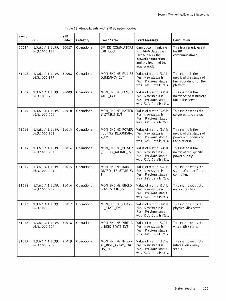
System Monitoring, Events, & Reporting
50027 .1.3.6.1.4.1.1139.16.3.1000.145
50027 Operational SM_DB_COMMUNICATION_ISSUE
Cannot communicate with RMG Database. Please check the network connection and the health of the master node.
This is a generic event for DB communications.
51008 .1.3.6.1.4.1.1139.16.3.1000.199
51008 Operational MON_ENGINE_FAN_REDUNDANCY_EVT
Value of metric '%s' is '%s'. New status is '%s'. Previous status was '%s'. Details: %s.
This metric is the metric of the status of fan redundancy on the platform.
51009 .1.3.6.1.4.1.1139.16.3.1000.200
51009 Operational MON_ENGINE_FAN_STATUS_EVT
Value of metric '%s' is '%s'. New status is '%s'. Previous status was '%s'. Details: %s.
This metric is the metric of the status of a fan in the server.
51010 .1.3.6.1.4.1.1139.16.3.1000.201
51010 Operational MON_ENGINE_BATTERY_STATUS_EVT
Value of metric '%s' is '%s'. New status is '%s'. Previous status was '%s'. Details: %s.
This metric reads the server battery status.
51013 .1.3.6.1.4.1.1139.16.3.1000.202
51013 Operational MON_ENGINE_POWER_SUPPLY_REDUNDANCY_EVT
Value of metric '%s' is '%s'. New status is '%s'. Previous status was '%s'. Details: %s.
This metric is the metric of the status of power redundancy on the platform.
51014 .1.3.6.1.4.1.1139.16.3.1000.203
51014 Operational MON_ENGINE_POWER_SUPPLY_METRIC_EVT
Value of metric '%s' is '%s'. New status is '%s'. Previous status was '%s'. Details: %s.
This metric is the metric of the specific power supply.
51015 .1.3.6.1.4.1.1139.16.3.1000.204
51015 Operational MON_ENGINE_RAID_CONTROLLER_STATE_EVT
Value of metric '%s' is '%s'. New status is '%s'. Previous status was '%s'. Details: %s.
This metric reads the status of a specific raid controller.
51016 .1.3.6.1.4.1.1139.16.3.1000.205
51016 Operational MON_ENGINE_ENCLOSURE_STATE_EVT
Value of metric '%s' is '%s'. New status is '%s'. Previous status was '%s'. Details: %s.
This metric reads the enclosure state.
51017 .1.3.6.1.4.1.1139.16.3.1000.206
51017 Operational MON_ENGINE_CHANNEL_STATE_EVT
Value of metric '%s' is '%s'. New status is '%s'. Previous status was '%s'. Details: %s.
This metric reads the physical disk state.
51018 .1.3.6.1.4.1.1139.16.3.1000.207
51018 Operational MON_ENGINE_VIRTUAL_DISK_STATE_EVT
Value of metric '%s' is '%s'. New status is '%s'. Previous status was '%s'. Details: %s.
This metric reads the virtual disk state.
51019 .1.3.6.1.4.1.1139.16.3.1000.208
51019 Operational MON_ENGINE_INTERNAL_DISK_ARRAY_STATUS_EVT
Value of metric '%s' is '%s'. New status is '%s'. Previous status was '%s'. Details: %s.
This metric reads the internal disk array status.
Table 15 Atmos Events with SYR Symptom Codes
Event ID OID
SYR Code Category Event Name Event Message Description
System reports 135

System Monitoring, Events, & Reporting
51021 .1.3.6.1.4.1.1139.16.3.1000.102
51021 Operational MON_ENGINE_TOTAL_MEMORY_UTILIZATION_EVT
Value of metric '%s' is '%s'. New status is '%s'. Previous status was '%s'. Details: %s.
This metric monitors the utilization of system memory including both physical memory and swap memory.
51024 .1.3.6.1.4.1.1139.16.3.1000.104
51024 Operational MON_ENGINE_FILE_SYSTEM_CAPACITY
Value of metric '%s' is '%s'. New status is '%s'. Previous status was '%s'. Details: %s.
This metric monitors the space utilization of a specified mount point.
51025 .1.3.6.1.4.1.1139.16.3.1000.106
51025 Operational MON_ENGINE_SERVICE_STATUS_EVT
Value of metric '%s' is '%s'. New status is '%s'. Previous status was '%s'. Details: %s.
The status of a service.
51026 .1.3.6.1.4.1.1139.16.3.1000.105
51026 Operational MON_ENGINE_SERVICE_MEMORY_USAGE_EVT
Value of metric '%s' is '%s'. New status is '%s'. Previous status was '%s'. Details: %s.
The memory usage of a service.
51027 .1.3.6.1.4.1.1139.16.3.1000.209
51027 Operational MON_ENGINE_TEMPERATURE_SENSOR_METRIC_EVT
Value of metric '%s' is '%s'. New status is '%s'. Previous status was '%s'. Details: %s.
"Temperature Sensor Metric is the metric of a specific temperature sensor, it reads the value of the temperature information."
51030 .1.3.6.1.4.1.1139.16.3.1000.111
51030 Configuration MON_RMG_STATUS %s %s has been %s This monitors the RMG status of an Atmos System.
51031 .1.3.6.1.4.1.1139.16.3.1000.110
51031 Configuration MON_IS_STATUS %s %s has been %s This monitors the Segment status of an Atmos System.
51032 .1.3.6.1.4.1.1139.16.3.1000.109
51032 Configuration MON_NODE_STATUS The status of node %s has changed to %s due to %s
This monitors the Node status of an Atmos System.
51044 .1.3.6.1.4.1.1139.16.3.1000.164
51044 Operational MON_ENGINE_NUM_CORES_EVT
Value of metric '%s' is '%s'. New status is '%s'. Previous status was '%s'. Details: %s.
This metric monitors the number of core dumps.
51047 .1.3.6.1.4.1.1139.16.3.1000.111
51047 Configuration MON_RMG_COMMUNICATION_STATUS_LOST
Communication with RMG %s was lost
This reports when the communication of an RMG is lost.
51049 .1.3.6.1.4.1.1139.16.3.1000.110
51049 Configuration MON_IS_COMMUNICATION_STATUS_LOST
Communication with installation segment %s has been lost
This reports when the communication of an IS is lost.
51051 .1.3.6.1.4.1.1139.16.3.1000.109
51051 Configuration MON_NODE_CONNECTION_STATUS_LOST
Connection with node %s was lost
This reports when the connection of a Node is lost.
51052 .1.3.6.1.4.1.1139.16.3.1000.109
51052 Configuration MON_NODE_COMMUNICATION_STATUS_LOST
Communication with node %s has been lost
This reports when the communication of a Node is lost.
Table 15 Atmos Events with SYR Symptom Codes
Event ID OID
SYR Code Category Event Name Event Message Description
136 EMC Atmos Version 2.1 Administrator’s Guide

System Monitoring, Events, & Reporting
Collecting system reports
The Collect System Report page is used to collect and then send Atmos configuration information to EMC support personnel. This feature is enabled and configured using the System Report Configuration page. Once the configuration information is collected, it is sent to a service automation tool called SYR, which serves as a repository for configuration data and is used to provide faster problem resolution.
Before you can collect system reports, you must configure system reporting. See “Configuring system reports.”
EMC recommends that you collect a system report after installation or upgrade, and both before and after making configuration changes. This provides EMC with a record of the current configuration of a customer's system, which can be helpful in resolving issues.
To collect system reports:
1. Log in as SysAdmin.
2. From the Navigation pane, click System Management > Service Only > Send System Report. Click Send on the popup to start the process.
51053 .1.3.6.1.4.1.1139.16.3.1000.110
51053 Configuration MON_IS_CONNECTION_STATUS_LOST
Connection with installation segment %s was lost
This reports when the connection with an IS is lost.
51054 .1.3.6.1.4.1.1139.16.3.1000.106
51054 Operational MON_ENGINE_CRIT_SERVICE_STATUS_EVT
Value of metric '%s' is '%s'. New status is '%s'. Previous status was '%s'. Details: %s.
The status of a Critical service.
51056 .1.3.6.1.4.1.1139.16.3.1000.174
51056 Operational MDS_DB_WOULD_ROLLBACK
An MDS transaction conflict has been detected. MDS instance %s has been shutdown.
BDB detected transaction conflict.
51057 .1.3.6.1.4.1.1139.16.3.1000.175
51057 Operational MDS_REP_PANIC A BDB database panic has been detected for MDS instance %s
BDB DB panic detected.
51058 .1.3.6.1.4.1.1139.16.3.1000.176
51058 Operational MDS_SAVE_ROLLBACK
MDS created a back up of its automatically rolled back transaction log.
51062 .1.3.6.1.4.1.1139.16.3.1000.149
51062 Operational MON_ENGINE_META_DATA_SERVICE_CAPACITY
Value of metric '%s' is '%s'. New status is '%s'. Previous status was '%s'. Details: %s.
This metric monitors the disk utilization of a specified Metadata Service instance.
51063 .1.3.6.1.4.1.1139.16.3.1000.160
51063 Operational MON_ENGINE_STORAGE_SERVICE_CAPACITY
Value of metric '%s' is '%s'. New status is '%s'. Previous status was '%s'. Details: %s.
This metric monitors the disk utilization of the Storage Service on this node.
Table 15 Atmos Events with SYR Symptom Codes
Event ID OID
SYR Code Category Event Name Event Message Description
System reports 137

System Monitoring, Events, & Reporting
The Collect System Report page appears, first indicating that system-report information collection is in process, then indicating that the information collection has completed and will be sent to SYR (EMC’s internal name for its System Reporting group).
If you navigate away from the Collect System Report page before the information collection completes, the information continues to be collected and, if it succeeds, the report is sent. Regardless of whether it succeeds, you do not receive any status information.
Log files and log collectionEach Atmos node has numerous logs. The MDS and SS, for example, maintain many log files that are used by Atmos to improve system performance.
A portion of the available disk space is consumed by log files. For example, the MDS maintains 1000 log files by default, which consumes about 10 GB of disk space (once MDS has claimed this disk space, it is reserved even if the objects that were written are deleted). The SS also maintains many log files, which are removed every 12 hours by default. Logging defaults can be changed. For more information, contact EMC Technical Support. EMC Technical Support may ask you to collect logs for debugging purposes.
To collect the logs:
1. Log in as SysAdmin.
2. From the Navigation pane, click System Management > Service Only > Collect Logs. A warning message appears:
138 EMC Atmos Version 2.1 Administrator’s Guide
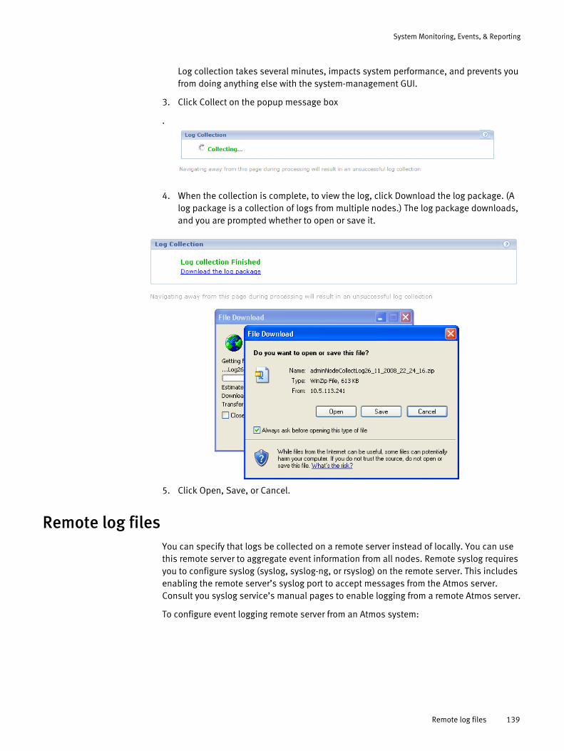
System Monitoring, Events, & Reporting
Log collection takes several minutes, impacts system performance, and prevents you from doing anything else with the system-management GUI.
3. Click Collect on the popup message box
.
4. When the collection is complete, to view the log, click Download the log package. (A log package is a collection of logs from multiple nodes.) The log package downloads, and you are prompted whether to open or save it.
5. Click Open, Save, or Cancel.
Remote log filesYou can specify that logs be collected on a remote server instead of locally. You can use this remote server to aggregate event information from all nodes. Remote syslog requires you to configure syslog (syslog, syslog-ng, or rsyslog) on the remote server. This includes enabling the remote server’s syslog port to accept messages from the Atmos server. Consult you syslog service’s manual pages to enable logging from a remote Atmos server.
To configure event logging remote server from an Atmos system:
Remote log files 139

System Monitoring, Events, & Reporting
1. From the Navigation pane, select System Management > Configuration > Notification > Remote Syslog.
2. Do one of the following:
• To configure remote syslog system-wide: set the Configuration for drop-down list to Default. This configuration will apply to all RMGs that do not have their own configuration.
• To configure remote syslog for one RMG: Set the Configuration for drop-down list to the target RMG name. If the RMG name is not listed, click Add to add the RMG to the drop-down list.
3. Specify the remote server in the Remote syslog host field.
4. Specify the syslog port of the remote server in the Remote syslog port field. The default is 514.
Monitoring events
Note: See Appendix A, “Atmos Event Reference” for information about individual events.
To view event summaries:
140 EMC Atmos Version 2.1 Administrator’s Guide

System Monitoring, Events, & Reporting
◆ If you are a SysAdmin, access the Events tab on the Node Information page (Node Dashboard).
◆ If you are a TenantAdmin, from the Navigation pane, select Tenant Management > Event Details.
Monitoring events 141

System Monitoring, Events, & Reporting
Both interfaces allow you to search for events by severity, category, and date range. The TenantAdmin version also contains the Hostname field. By default, the TenantAdmin see the events for the node (hostname) that the admin is logged into. That TenantAdmin may also be assigned access nodes and the Hostname field allows the TenantAdmin to view events from these nodes.
You can access the event detail interfaces using the event summary provided at the top of the System Dashboard, RMG Dashboard, or Node Dashboard. Event summary links are also available to the TenantAdmin from the Tenant Dashboard
.
Note: Event counts are approximate as event counts at the node, RMG, and system level are being refreshed at different times.
To use the event summary links on the System, RMG, Node, or Tenant Dashboard:
1. Log in as SysAdmin.
2. Or, log in as the TenantAdmin. The Tenant Dashboard appears.
3. Select a time period from the drop-down list to see the event type counts for that time period.
4. Choose the event type by clicking the link after the type icon. Table 16 describes the event icons.
Table 16 Event Category Icons
Event Category Icon Description
Critical condition
Status messages about critical condition messages requiring immediate attention.
Error Status messages about an error condition.
Warning Status messages about less than optimal conditions.
Information Routine status messages or the status of an event that has not returned to a normal state.
142 EMC Atmos Version 2.1 Administrator’s Guide
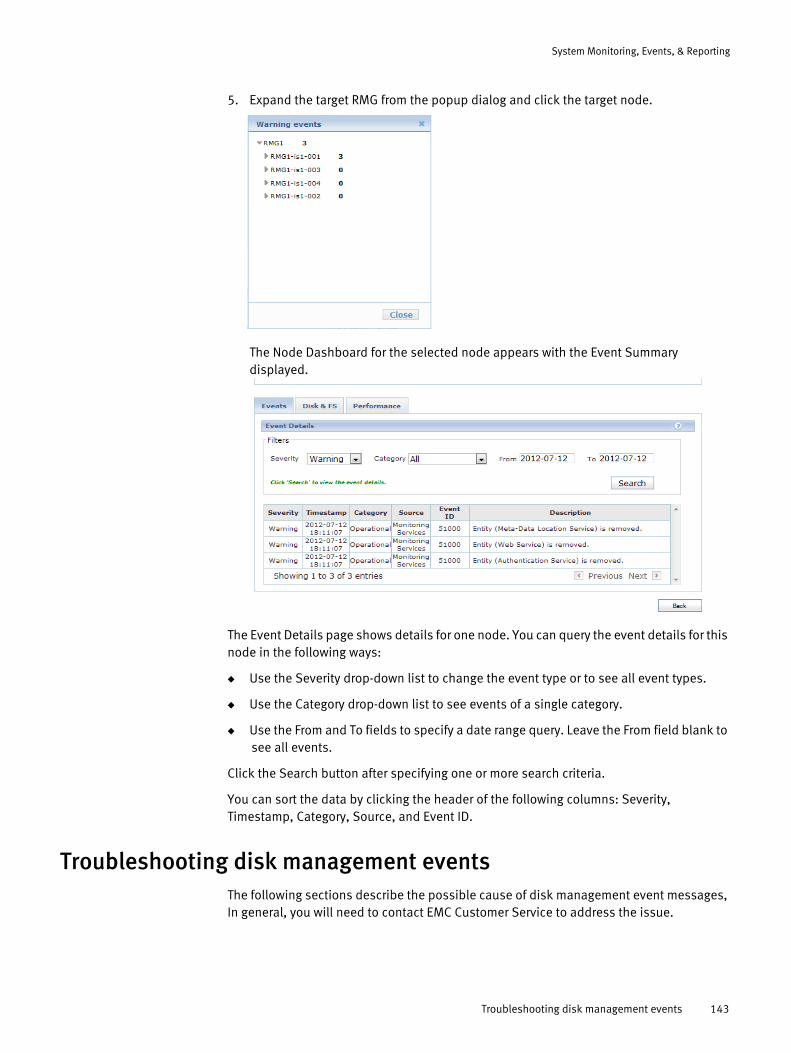
System Monitoring, Events, & Reporting
5. Expand the target RMG from the popup dialog and click the target node.
The Node Dashboard for the selected node appears with the Event Summary displayed.
The Event Details page shows details for one node. You can query the event details for this node in the following ways:
◆ Use the Severity drop-down list to change the event type or to see all event types.
◆ Use the Category drop-down list to see events of a single category.
◆ Use the From and To fields to specify a date range query. Leave the From field blank to see all events.
Click the Search button after specifying one or more search criteria.
You can sort the data by clicking the header of the following columns: Severity, Timestamp, Category, Source, and Event ID.
Troubleshooting disk management eventsThe following sections describe the possible cause of disk management event messages, In general, you will need to contact EMC Customer Service to address the issue.
Troubleshooting disk management events 143

System Monitoring, Events, & Reporting
DM_FAILED_PARTITION_EVT
Event ID: 40000
Event String: Failed to partition disk %s in slot %s. This disk will be placed in the DISK_STATUS_CRITICAL state and will not be used
Trap OID: .1.3.6.1.4.1.1139.16.3.1000.155
Cause: Partitioning the disk (specifically, running the sgdisk command) has failed. In this case, Atmos has retried partitioning the disk already, and all attempts have failed. Investigation into this failure is required. Typically this would fail because of hardware failure.
Note that this event is very rare and hard to reproduce, as all partitioning is done automatically.
DM_FAILED_FORMAT_EVT
Event ID: 40001
Event String: Failed to format partition on disk %s in slot %s. This disk will be placed in the DISK_STATUS_CRITICAL state and will not be used.
Trap OID: .1.3.6.1.4.1.1139.16.3.1000.155
Cause: Formatting the disk (specifically, running the mkfs command) has failed. In this case, Atmos has retried formatting the disk already, and all attempts have failed. Investigation into this failure is required. Typically this would fail because of hardware failure.
Note that this event is very rare and hard to reproduce, as all formatting is done automatically.
DM_DISK_UNAVAILABLE
Event ID: 40006
Event String: Disk %s with filesystem %s in DAE %s slot %s has become unavailable. The disk will be put into the DISK_STATUS_REMOVED state.
Trap OID: .1.3.6.1.4.1.1139.16.3.1000.156
Cause: This means that a disk has been lost. This can be caused by a DAE failure, power failure, flapping, or the disk being manually removed. Other circumstances could also lead to the disk being lost. It is important to note that this message indicates that the Disk Management system knew about the disk before it was lost. In other words, it was once connected to the node but is not anymore.
DM_DAE_UNAVAILABLE
Event ID: 40007
Event String: DAE element %s has become unavailable.
Trap OID: .1.3.6.1.4.1.1139.16.3.1000.157
144 EMC Atmos Version 2.1 Administrator’s Guide
System Monitoring, Events, & Reporting
Cause: The DAE has been lost. This can happen due to power supply failure, or an unplugged cable, and so on.
DM_DISK_ERROR
Event ID: 40008
Event String: An error has occurred on filesystem %s on disk %s in DAE %s slot %s. The disk is being put into the DISK_STATUS_CRITICAL state.
Trap OID: .1.3.6.1.4.1.1139.16.3.1000.158
Cause: An I/O error has occurred on a given filesystem. As such, the service (either MDS or SS) has indicated to the Disk Management system that the filesystem should no longer be used. The filesystem is now unmounted and unconfigured from the service.
An I/O error can have a number of causes. One example is a DAE failure; perhaps a disk was not properly connected or was losing power. In addition, an internal error could have occurred from which the Disk Management system automatically recovered. For this reason, the following factors need to be determined:
◆ If the filesystem is still unconfigured for use
◆ If the I/O error occurred because of some external means, such as a DAE failure.
DM_MOUNT_FAILED
Event ID: 40014
Event String: Failed to mount filesystem %s. Error details: %s
Trap OID: .1.3.6.1.4.1.1139.16.3.1000.143
Cause: This alert indicates that mounting the filesystem failed. Some situations that can cause this are:
◆ The filesystem was temporarily unavailable when the mount was attempted.
◆ Hardware error.
Cause: It must be determined which of these situations caused the mount failure. This can be done by examining /var/log/maui/dm.log, and noting the output and return value of the mount command. Note that this problem is rare and difficult to reproduce.
DM_UUIDS_NOT_FOUND
Event ID: 40018
Event String: Disk UUID's are not found on this machine. If this is a virtual machine, please add 'disk.enableUUID = TRUE' to the virtual machine settings. For more details, see the installation guide.
Trap OID: .1.3.6.1.4.1.1139.16.3.1000.156
Cause: This message is only valid in ESXi/Vmware. If this message is seen, that means that disk serial numbers are not enabled. As a result, disk management cannot manage any disk resources. This means that no disks will be assigned to MDS or SS.
Troubleshooting disk management events 145
System Monitoring, Events, & Reporting
DM_FILESYSTEM_NOT_IN_USE
Event ID: 40022
Event String: Filesystem is no longer being used by services. Filesystem: %s Disk: %s DAE %s slot %s
Trap OID: .1.3.6.1.4.1.1139.16.3.1000.166
Cause: This alert indicates that a service has been unconfigured to use a specific filesystem. This alert can happen because of an I/O error or if the disk was unavailable for a certain amount of time. This alert should be accompanied with 40008 or 40006, which indicate I/O error or disk unavailability, respectively.
146 EMC Atmos Version 2.1 Administrator’s Guide

CHAPTER 7Getting Performance Data
This chapter explains how to obtain performance data from any workstation that can access an Atmos server. This chapter includes the following topics:
◆ Overview............................................................................................................... 148◆ Example: Getting the statistics.............................................................................. 148◆ Example: Resetting the counters ........................................................................... 150
Getting Performance Data 147
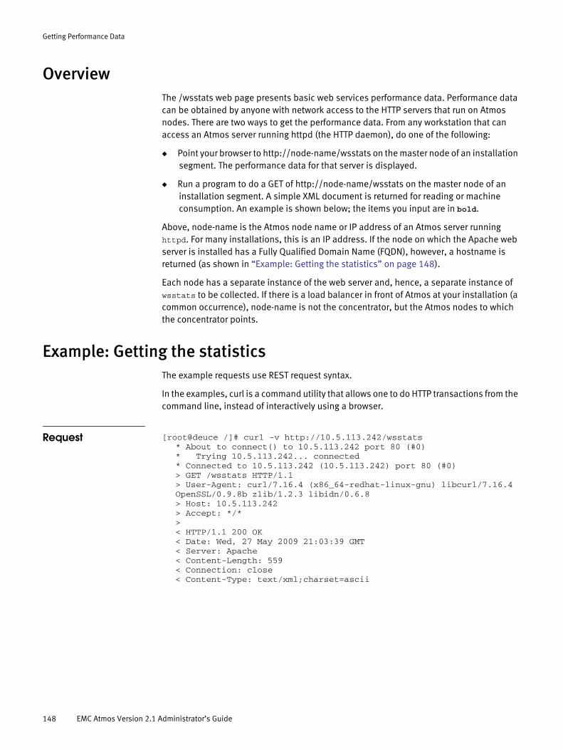
Getting Performance Data
OverviewThe /wsstats web page presents basic web services performance data. Performance data can be obtained by anyone with network access to the HTTP servers that run on Atmos nodes. There are two ways to get the performance data. From any workstation that can access an Atmos server running httpd (the HTTP daemon), do one of the following:
◆ Point your browser to http://node-name/wsstats on the master node of an installation segment. The performance data for that server is displayed.
◆ Run a program to do a GET of http://node-name/wsstats on the master node of an installation segment. A simple XML document is returned for reading or machine consumption. An example is shown below; the items you input are in bold.
Above, node-name is the Atmos node name or IP address of an Atmos server running httpd. For many installations, this is an IP address. If the node on which the Apache web server is installed has a Fully Qualified Domain Name (FQDN), however, a hostname is returned (as shown in “Example: Getting the statistics” on page 148).
Each node has a separate instance of the web server and, hence, a separate instance of wsstats to be collected. If there is a load balancer in front of Atmos at your installation (a common occurrence), node-name is not the concentrator, but the Atmos nodes to which the concentrator points.
Example: Getting the statisticsThe example requests use REST request syntax.
In the examples, curl is a command utility that allows one to do HTTP transactions from the command line, instead of interactively using a browser.
Request [root@deuce /]# curl -v http://10.5.113.242/wsstats* About to connect() to 10.5.113.242 port 80 (#0)* Trying 10.5.113.242... connected* Connected to 10.5.113.242 (10.5.113.242) port 80 (#0)> GET /wsstats HTTP/1.1> User-Agent: curl/7.16.4 (x86_64-redhat-linux-gnu) libcurl/7.16.4OpenSSL/0.9.8b zlib/1.2.3 libidn/0.6.8> Host: 10.5.113.242> Accept: */*>< HTTP/1.1 200 OK< Date: Wed, 27 May 2009 21:03:39 GMT< Server: Apache< Content-Length: 559< Connection: close< Content-Type: text/xml;charset=ascii
148 EMC Atmos Version 2.1 Administrator’s Guide

Getting Performance Data
Response <WSStat><Node name="10.5.113.242"/><ReadsPerSec>675.80</ReadsPerSec><WritesPerSec>1102.43</WritesPerSec><DeletesPerSec>171.57</DeletesPerSec><TransPerSec>1949.80</TransPerSec><MeanReadLatencyMS>4.557</MeanReadLatencyMS><MeanWriteLatencyMS>153.282</MeanWriteLatencyMS><MeanLatencyMS>89.206</MeanLatencyMS><Reads>31087</Reads><Writes>50712</Writes><Deletes>7892</Deletes><Total>89691</Total><ReadLatencyMS>141660</ReadLatencyMS><WriteLatencyMS>7773233</WriteLatencyMS><DeleteLatencyMS>86112</DeleteLatencyMS><UptimeMS>46711</UptimeMS></WSStat>* Closing connection #0[root@deuce /]#
Browser output
Output fields The output is interpreted as follows:
◆ Node name is the server name in the node-name field of the request for the /wsstats page, as defined by the Apache web server when it logs.
◆ Reads, Writes, and Deletes are defined in Table 17.
◆ Total is the sum of reads, writes, and deletes.
◆ The per-second (PerSec) rate for each of the three transaction types is calculated as the count divided by the total uptime since the last server restart.
Table 17 Reads, Writes, and Deletes
REST SOAP
Reads GET and HEAD transactions List, Get, and Read transactions
Writes PUT and POST transactions Create, Set, Update, and Version Transactions
Deletes DELETE transactions Delete transactions
Example: Getting the statistics 149
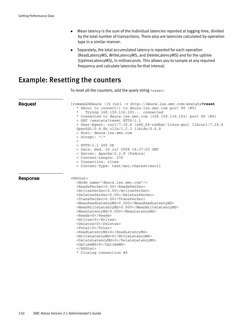
Getting Performance Data
◆ Mean latency is the sum of the individual latencies reported at logging time, divided by the total number of transactions. There also are latencies calculated by operation type in a similar manner.
◆ Separately, the total accumulated latency is reported for each operation (ReadLatencyMS, WriteLatencyMS, and DeleteLatencyMS) and for the uptime (UptimeLatencyMS), in milliseconds. This allows you to sample at any required frequency and calculate latencies for that interval.
Example: Resetting the countersTo reset all the counters, add the query string ?reset:
Request [romanm2@deuce ~]$ curl -v http://deuce.lss.emc.com/wsstats?reset* About to connect() to deuce.lss.emc.com port 80 (#0)* Trying 168.159.116.103... connected* Connected to deuce.lss.emc.com (168.159.116.103) port 80 (#0)> GET /wsstats?reset HTTP/1.1> User-Agent: curl/7.16.4 (x86_64-redhat-linux-gnu) libcurl/7.16.4OpenSSL/0.9.8b zlib/1.2.3 libidn/0.6.8> Host: deuce.lss.emc.com> Accept: */*>< HTTP/1.1 200 OK< Date: Wed, 30 Jul 2008 18:27:03 GMT< Server: Apache/2.2.8 (Fedora)< Content-Length: 276< Connection: close< Content-Type: text/xml;charset=ascii
Response <WSStat><Node name="deuce.lss.emc.com"/><ReadsPerSec>0.00</ReadsPerSec><WritesPerSec>0.00</WritesPerSec><DeletesPerSec>0.00</DeletesPerSec><TransPerSec>0.00</TransPerSec><MeanReadLatencyMS>0.000</MeanReadLatencyMS><MeanWriteLatencyMS>0.000</MeanWriteLatencyMS><MeanLatencyMS>0.000</MeanLatencyMS><Reads>0</Reads><Writes>0</Writes><Deletes>0</Deletes><Total>0</Total><ReadLatencyMS>0</ReadLatencyMS><WriteLatencyMS>0</WriteLatencyMS><DeleteLatencyMS>0</DeleteLatencyMS><UptimeMS>0</UptimeMS></WSStat>* Closing connection #0
150 EMC Atmos Version 2.1 Administrator’s Guide
PART 2
TenantAdmin
This part includes the following chapters:
Chapter 8, “TenantAdmin Basics.”
Provides a brief overview of the TenantAdmin role.
Chapter 9, “Managing Subtenants.”
Describes how users in the TenantAdmin role manage subtenants and access nodes.
Chapter 10, “Managing Policies.”
Introduces Atmos policy specifications, policy selectors, and policy transition specifications (for defining age-based policies).


CHAPTER 8TenantAdmin Basics
Describes TenantAdmin tasks including:
◆ Overview............................................................................................................... 154◆ Logging in ............................................................................................................. 154◆ Using the Tenant Dashboard ................................................................................. 156◆ Modifying TenantAdmin Information ..................................................................... 157◆ Quick reference..................................................................................................... 157
TenantAdmin Basics 153
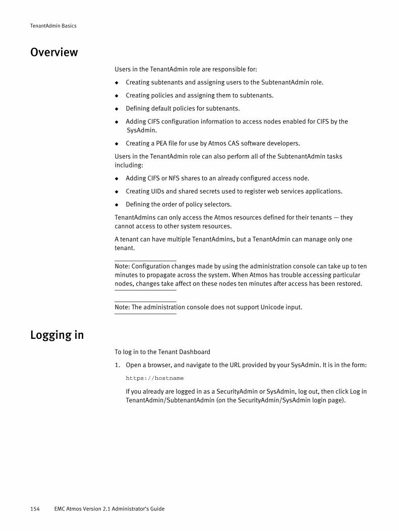
TenantAdmin Basics
OverviewUsers in the TenantAdmin role are responsible for:
◆ Creating subtenants and assigning users to the SubtenantAdmin role.
◆ Creating policies and assigning them to subtenants.
◆ Defining default policies for subtenants.
◆ Adding CIFS configuration information to access nodes enabled for CIFS by the SysAdmin.
◆ Creating a PEA file for use by Atmos CAS software developers.
Users in the TenantAdmin role can also perform all of the SubtenantAdmin tasks including:
◆ Adding CIFS or NFS shares to an already configured access node.
◆ Creating UIDs and shared secrets used to register web services applications.
◆ Defining the order of policy selectors.
TenantAdmins can only access the Atmos resources defined for their tenants — they cannot access to other system resources.
A tenant can have multiple TenantAdmins, but a TenantAdmin can manage only one tenant.
Note: Configuration changes made by using the administration console can take up to ten minutes to propagate across the system. When Atmos has trouble accessing particular nodes, changes take affect on these nodes ten minutes after access has been restored.
Note: The administration console does not support Unicode input.
Logging inTo log in to the Tenant Dashboard
1. Open a browser, and navigate to the URL provided by your SysAdmin. It is in the form:
https://hostname
If you already are logged in as a SecurityAdmin or SysAdmin, log out, then click Log in TenantAdmin/SubtenantAdmin (on the SecurityAdmin/SysAdmin login page).
154 EMC Atmos Version 2.1 Administrator’s Guide
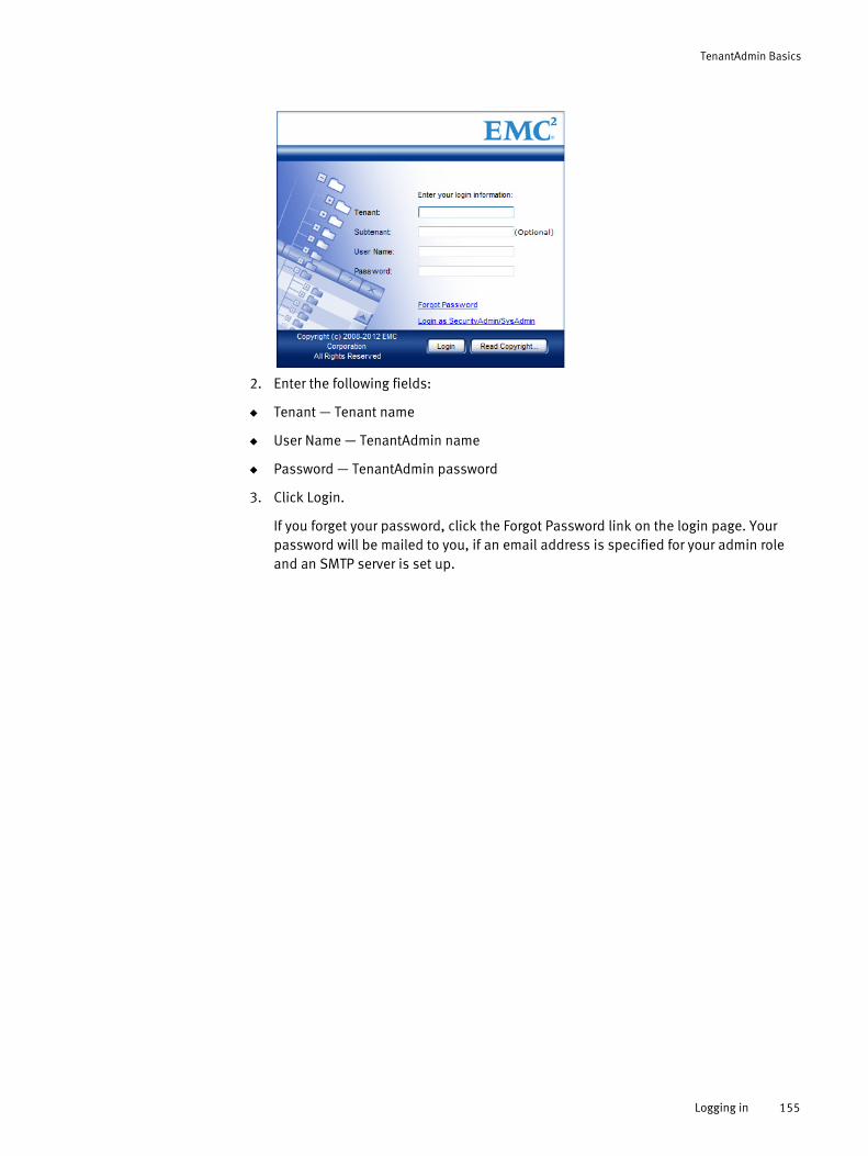
TenantAdmin Basics
2. Enter the following fields:
◆ Tenant — Tenant name
◆ User Name — TenantAdmin name
◆ Password — TenantAdmin password
3. Click Login.
If you forget your password, click the Forgot Password link on the login page. Your password will be mailed to you, if an email address is specified for your admin role and an SMTP server is set up.
Logging in 155
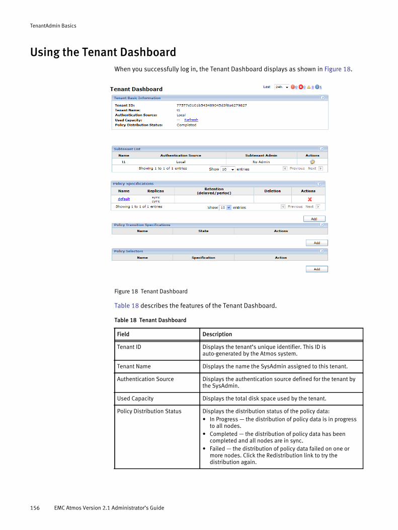
TenantAdmin Basics
Using the Tenant DashboardWhen you successfully log in, the Tenant Dashboard displays as shown in Figure 18.
Figure 18 Tenant Dashboard
Table 18 describes the features of the Tenant Dashboard.
Table 18 Tenant Dashboard
Field Description
Tenant ID Displays the tenant’s unique identifier. This ID is auto-generated by the Atmos system.
Tenant Name Displays the name the SysAdmin assigned to this tenant.
Authentication Source Displays the authentication source defined for the tenant by the SysAdmin.
Used Capacity Displays the total disk space used by the tenant.
Policy Distribution Status Displays the distribution status of the policy data:• In Progress — the distribution of policy data is in progress
to all nodes. • Completed — the distribution of policy data has been
completed and all nodes are in sync. • Failed — the distribution of policy data failed on one or
more nodes. Click the Redistribution link to try the distribution again.
156 EMC Atmos Version 2.1 Administrator’s Guide
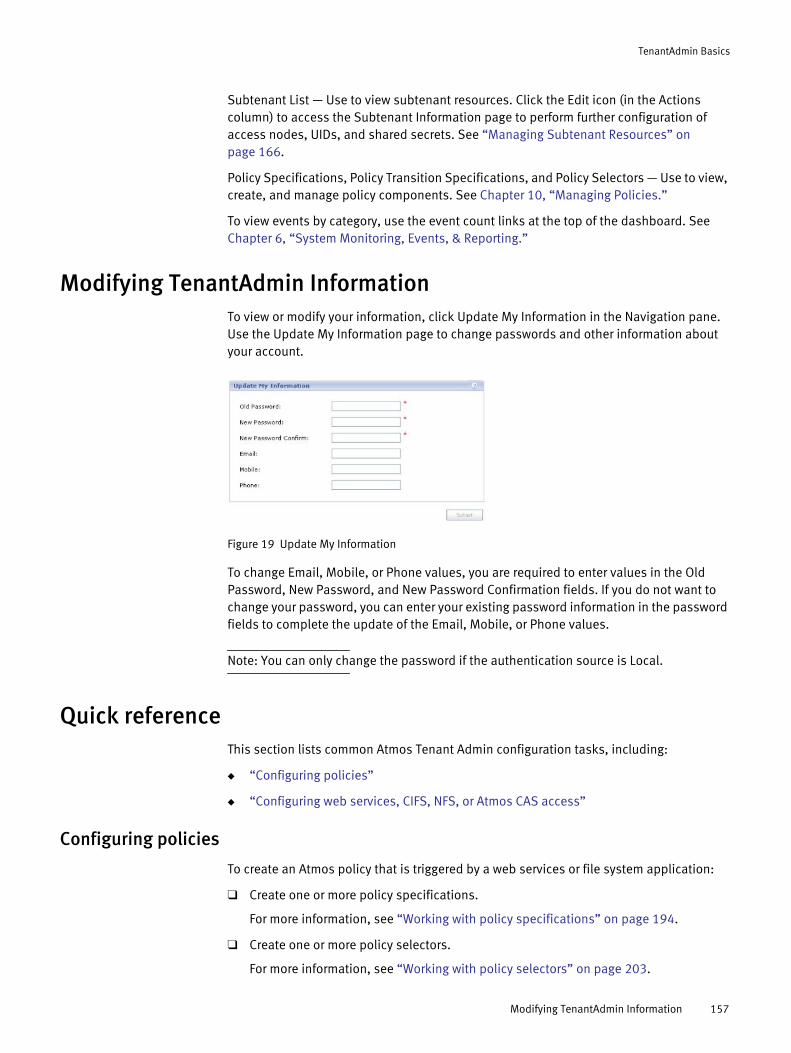
TenantAdmin Basics
Subtenant List — Use to view subtenant resources. Click the Edit icon (in the Actions column) to access the Subtenant Information page to perform further configuration of access nodes, UIDs, and shared secrets. See “Managing Subtenant Resources” on page 166.
Policy Specifications, Policy Transition Specifications, and Policy Selectors — Use to view, create, and manage policy components. See Chapter 10, “Managing Policies.”
To view events by category, use the event count links at the top of the dashboard. See Chapter 6, “System Monitoring, Events, & Reporting.”
Modifying TenantAdmin InformationTo view or modify your information, click Update My Information in the Navigation pane. Use the Update My Information page to change passwords and other information about your account.
Figure 19 Update My Information
To change Email, Mobile, or Phone values, you are required to enter values in the Old Password, New Password, and New Password Confirmation fields. If you do not want to change your password, you can enter your existing password information in the password fields to complete the update of the Email, Mobile, or Phone values.
Note: You can only change the password if the authentication source is Local.
Quick referenceThis section lists common Atmos Tenant Admin configuration tasks, including:
◆ “Configuring policies”
◆ “Configuring web services, CIFS, NFS, or Atmos CAS access”
Configuring policies
To create an Atmos policy that is triggered by a web services or file system application:
❑ Create one or more policy specifications.
For more information, see “Working with policy specifications” on page 194.
❑ Create one or more policy selectors.
For more information, see “Working with policy selectors” on page 203.
Modifying TenantAdmin Information 157
TenantAdmin Basics
❑ Assign the policy selectors to one or more subtenants.
For more information, see “Assigning policy selectors to subtenants” on page 207.
❑ Verify that the order of policy selectors is correct for your business model.
For more information, see “Reordering policy selectors” on page 187.
❑ Assign a default policy to each subtenant.
For more information, see “Assigning a default policy” on page 187.
To create an Atmos policy that is triggered by age-based conditions:
❑ Create one or more policy specifications.
For more information, see “Working with policy specifications” on page 194.
❑ Create the policy transition specification.
For more information, see “Working with policy transition specifications” on page 208.
❑ Create a policy selector and assign it to the first policy specification in the policy transition specification.
For more information, see “Working with policy selectors” on page 203.
❑ Assign the policy selector to one or more subtenants.
For more information, see “Assigning policy selectors to subtenants” on page 207.
❑ Verify that the order of policy selectors is correct for your business model.
For more information, see “Reordering policy selectors” on page 187.
❑ Assign a default policy to each subtenant.
For more information, see “Assigning a default policy” on page 187.
Configuring web services, CIFS, NFS, or Atmos CAS access
◆ “Setting up web services/S3 access”
◆ “Setting up CIFS access”
◆ “Setting up NFS access”
◆ “Setting up Atmos CAS access”
Note: Before you configure CIFS or NFS access to Atmos, you should synchronize your external server’s times with your Atmos NTP server time. For more information, see “Configuring the system master serial number” on page 74.
Setting up web services/S3 access ❑ Verify that your SysAdmin assigned one or more access nodes, and that they are
enabled for web services access.
❑ If you plan to configure your Atmos system with more than just the default subtenant, follow the steps for “Creating tenants” and “Creating a TenantAdmin”.
❑ Use the Subtenant Information page to configure the Atmos credentials needed for web service/S3 access to Atmos.
For more information, see “Creating a UID and shared secret” on page 168.
158 EMC Atmos Version 2.1 Administrator’s Guide
TenantAdmin Basics
❑ Provide the shared secret/UID to the web services/S3 programmers writing Atmos applications.
Setting up CIFS access❑ Verify that your SysAdmin assigned one or more access nodes, and that they are
enabled for CIFS access.
❑ If you plan to configure your Atmos system with more than just the default subtenant, follow the steps for “Creating tenants” and “Creating a TenantAdmin”.
❑ Use the Subtenant Information page to configure the CIFS node information.
For more information, see “Configuring CIFS Node Properties” on page 170.
❑ Continue using the Subtenant Information page to add the CIFS share.
For more information, see “Adding or Editing a CIFS Share” on page 173.
Setting up NFS access ❑ Verify that your SysAdmin assigned one or more access nodes to you, and that they
are enabled for NFS access.
❑ If you plan to configure your Atmos system with more than just the default subtenant, follow the steps for “Creating tenants” and “Creating a TenantAdmin”.
❑ Use the Subtenant Information page to configure the NFS share.
For more information, see “Configuring NFS access nodes” on page 176.
Setting up Atmos CAS access ❑ Verify that your SysAdmin assigned one or more access nodes to you, and that they
are enabled for Atmos CAS access.
❑ If you plan to configure your Atmos system with more than just the default subtenant, follow the steps for “Creating tenants” and “Creating a TenantAdmin”.
❑ Create a CAS PEA file.
For more information, see “Setting up CAS Policy-Driven Storage” on page 178.
❑ Provide the application developer with the following information used for authentication:
❑ A PEA file.
❑ The Subtenant ID, user ID and secret (if the PEA file is not used in the connection string, you can use this information separately in the connection string).
Quick reference 159

TenantAdmin Basics
160 EMC Atmos Version 2.1 Administrator’s Guide
CHAPTER 9Managing Subtenants
Describes how users in the TenantAdmin role manage subtenants. It includes the following topics:
◆ About subtenants ................................................................................................. 162◆ Listing subtenants ................................................................................................ 163◆ Creating subtenants.............................................................................................. 163◆ Renaming subtenants ........................................................................................... 163◆ Managing SubtenantAdmins................................................................................. 164◆ Managing Subtenant Resources............................................................................ 166◆ Setting up CAS Policy-Driven Storage .................................................................... 178
Note: Many of the tasks described in the section on managing subtenant resources can also be performed by the SubtenantAdmin from the Subtenant dashboard.
Managing Subtenants 161

Managing Subtenants
About subtenantsAtmos is designed to support multiple separate groups of resources known as tenants. An Atmos tenant can be further subdivided into subsets of resources called subtenants which represent a logical partition of overall system resources. Each subtenant has their own set of policy selectors, applications, and data. As the TenantAdmin, you are responsible for managing subtenants by:
◆ Creating subtenants and assigning users to the SubtenantAdmin role.
◆ Assigning policy selectors to subtenants.
◆ Assigning a default policy to subtenants.
The following tasks can be performed by both the TenantAdmin and by the SubtenantAdmin:
◆ Reordering policy selectors.
◆ Creating UIDs and shared secrets for web services applications.
◆ Configuring access nodes for NFS and CIFS (if the SysAdmin has enabled the access nodes.
When a tenant is created, Atmos automatically creates a default subtenant of the same name, ID, and authentication source as the tenant. It also creates a subtenant namespace (located under the tenant namespace). You cannot delete the default subtenant.
Subtenant namespace
Each subtenant owns a namespace that is independent of the namespaces of other subtenants within the same tenant. At the top of subtenant namespace is a subtenant root directory.
◆ The subtenant root directory is located in the location (RMG) where the operation for subtenant creation was invoked either through the system-management GUI or the system management API.
◆ The files and directories created by user applications are located under the subtenant root directories.
◆ By default, the metadata records for directories and files are created in the same location (RMG) as the parent directory where the directories and files (user data) are created. You can change the metadata location default behavior by specifying the metadata location in a policy specification.
For more information about metadata location specifications, see “Metadata location” on page 195.
Atmos distributes the namespace to best utilize system resources. Efficient management of the namespace is very important for overall system performance. The namespace should be balanced, one directory should not contain all or a large portion of all files.
Namespace considerations are similar for both Atmos file-system access and Web services access with namespace addressing.
162 EMC Atmos Version 2.1 Administrator’s Guide

Managing Subtenants
Listing subtenantsLog in TenantAdmin. The Subtenant List area is shown in Figure 20.
Figure 20 Subtenant List
Creating subtenants
Note: If you are running Atmos LE, you are allowed to create a maximum of one subtenant.
1. Log in as TenantAdmin.
2. In the Subtenant List area, click Add.
3. Specify an Authentication Source (Local or Remote).
The system lets you authenticate subtenant accounts locally (internal) to the platform or remotely (external), using a preconfigured LDAP server.
Note: Once a subtenant is created, you cannot modify its authentication source.
4. Specify a Subtenant Name, then click Create.
The Subtenant name must be unique. It can be up to 255 characters long, and can include alphanumeric characters, and the underscore (_) and dot (.) symbols.
Renaming subtenants
Note: You cannot rename a tenant's default subtenant directly. However, if you rename a tenant, both its name and its default subtenant’s name are changed.
1. Log in TenantAdmin.
2. In the Subtenant List area, click Edit next to the subtenant you want to modify. The Subtenant Information page appears.
Listing subtenants 163
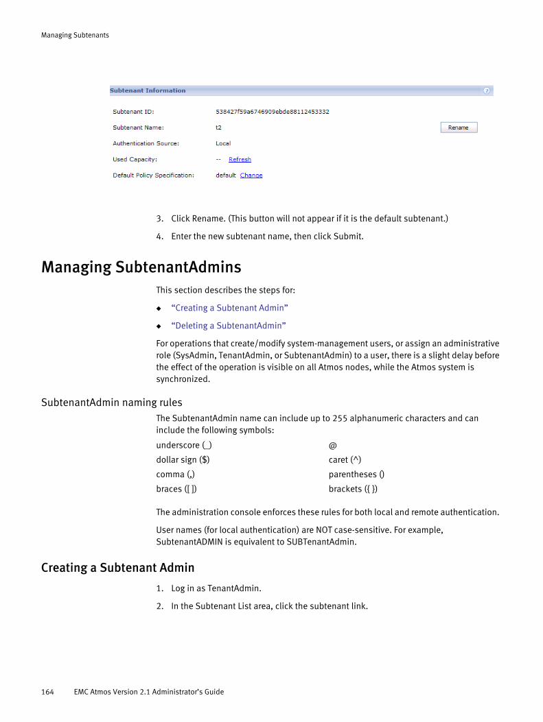
Managing Subtenants
3. Click Rename. (This button will not appear if it is the default subtenant.)
4. Enter the new subtenant name, then click Submit.
Managing SubtenantAdminsThis section describes the steps for:
◆ “Creating a Subtenant Admin”
◆ “Deleting a SubtenantAdmin”
For operations that create/modify system-management users, or assign an administrative role (SysAdmin, TenantAdmin, or SubtenantAdmin) to a user, there is a slight delay before the effect of the operation is visible on all Atmos nodes, while the Atmos system is synchronized.
SubtenantAdmin naming rulesThe SubtenantAdmin name can include up to 255 alphanumeric characters and can include the following symbols:
The administration console enforces these rules for both local and remote authentication.
User names (for local authentication) are NOT case-sensitive. For example, SubtenantADMIN is equivalent to SUBTenantAdmin.
Creating a Subtenant Admin
1. Log in as TenantAdmin.
2. In the Subtenant List area, click the subtenant link.
underscore (_) @
dollar sign ($) caret (^)
comma (,) parentheses ()
braces ([ ]) brackets ({ })
164 EMC Atmos Version 2.1 Administrator’s Guide

Managing Subtenants
3. In the Subtenant Admins area, click Add.
4. Enter the User Name for this SubtenantAdmin, and click Save.
The user name field can include alphanumeric characters and the underscore (_), dot (.) or @ symbols. It must be at least one character but not more than 255 characters.
If the authentication source is local, and the user does not exist, Atmos prompts you to add the user.
5. Click OK to add the new (local) user to the system. You are prompted to enter the password and other information about the account.
6. Enter the required Password and Password Confirm fields and any optional fields.
Although the Email field is optional, if the TenantAdmin forgets his password, he can get it emailed to him — but only if this field is completed.
7. Click Save to return to the Tenant Dashboard.
Managing SubtenantAdmins 165

Managing Subtenants
Deleting a SubtenantAdmin
1. Log in TenantAdmin.
2. In the Subtenant List area, click the subtenant link.
3. In the Subtenant Admins area, in the row for the SubtenantAdmin you want to remove, click Remove Role.
4. In the pop-up dialog asking you to confirm, click OK.
This operation does not delete the user from the authentication source, it removes them from the SubTenantAdmin role.
Managing Subtenant ResourcesThis section describes how to manage subtenant resources which include:
◆ “Creating a UID and shared secret”
◆ “Configuring CIFS access nodes”
◆ “Configuring NFS access nodes”
◆ “Setting up CAS Policy-Driven Storage”
◆ “Reordering policy selectors”
◆ “Assigning a default policy”
You use the Subtenant Information page to manage the subtenant resources. To access the Subtenant Information page:
1. Log in as a TenantAdmin.
2. On the Tenant Dashboard, in the Subtenant List area, click the subtenant name link.
166 EMC Atmos Version 2.1 Administrator’s Guide
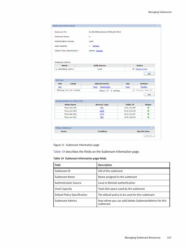
Managing Subtenants
Figure 21 Subtenant Information page
Table 19 describes the fields on the Subtenant Information page.
Table 19 Subtenant Information page fields
Field Description
Subtenant ID UID of the subtenant
Subtenant Name Name assigned to the subtenant
Authentication Source Local or Remote authentication
Used Capacity Total disk space used by the subtenant
Default Policy Specification The default policy to be used for this subtenant.
Subtenant Admins Area where you can add/delete SubtenantAdmins for this subtenant.
Managing Subtenant Resources 167

Managing Subtenants
Creating a UID and shared secret
A UID is a unique identifier that represents a user or application that wants to read or write data to the Atmos system using the REST, S3, or SOAP API. To perform operations on Atmos CAS using the Atmos CAS API, applications must use a combination of UID and subtenant ID in the connection string. TenantAdmins and SubtenantAdmins are responsible for managing them.
When you create a UID, Atmos generates a unique key (or shared secret) for it. For Atmos CAS, applications may use a PEA (Pool Entry Authorization) file to store the credentials for the UID and subtenant ID combination. Once these credentials are created, you can provide them to the application developer who will use the combination to authenticate their application on web service requests.
To create a UID:
Note: If you are running Atmos LE, you are allowed to create a maximum of 50 UIDs.
1. Go to the UID List area, then click Add. The Add UID page appears.
2. In the UID field type a new UID that is unique within the subtenant. It is a string that can:
• Be a maximum of 255 characters.
• Contain the letters a to z (both upper and lower case) and digits 0 to 9.
• The set of valid special characters depends on the authentication source:
– A UID stored in an LDAP source can support these special characters: at sign(@), period (.), and underscore (_).
If unsupported characters are used, Atmos cannot retrieve the corresponding shared secret for the UID. This limitation does not apply to UIDs stored in the local lockbox.
UID List Information about Web-service UIDs belonging to this subtenant. A UID can be assigned to only one subtenant. To add a UID to this subtenant, click Add, then see “ Creating a UID and shared secret” on page 168.This area of the page also enables you to regenerate the secret key (shared secret), disable a UID, and email the secret key to the email address associated with this UID. To update the email information for a UID, click the UID.
Access Nodes for NFS/CIFS Lists nodes with the NFS or CIFS service which can be accessed by this subtenant.
Policy Selectors Lists the policy selectors that are associated with the subtenant
Table 19 Subtenant Information page fields
Field Description
168 EMC Atmos Version 2.1 Administrator’s Guide

Managing Subtenants
– A UID stored in the local lockbox can include the following special characters: - _ @ $ ^ , ; | [ ] ( ) and { }
Note: If the UID will be used with Atmos Cloud Delivery Platform (ACDP), do not use the pipe symbol (|) or you will be unable to gather usage information for that UID as ACDP interprets this character as a delimiter.
3. Optionally, enter an email address. This is used to email the secret key, if that action is specified on the Subtenant Dashboard.
4. Click Add. The Subtenant Information page appears, listing the new UID and the Shared Secret that the system generated for it.
Note: There is a slight delay before the UID is available on all Atmos nodes.
5. Give this information to your application developer for use in authenticating access to the system for Web-service requests.
Disabling, enabling, and regenerating the shared secretYou can disable, enable, or regenerate the shared secret. Remember that:
◆ When you disable a shared secret, the application is no longer able to access the system through web services.
◆ To restore access, enable the shared secret.
◆ When you regenerate a shared secret, the application has to use the new shared secret to access the system.
◆ You cannot revert to a previous shared secret after the regenerate shared secret operation has been performed.
Configuring CIFS access nodes
If your SysAdmin has assigned Atmos access nodes and enabled CIFS access, you need to do a few more steps before the access nodes can be used. The steps include:
◆ “Configuring CIFS Node Properties”
◆ “Adding or Editing a CIFS Share”
Perform all CIFS configuration through the system-management GUI — do not modify the Samba/CIFS configuration file manually.
Atmos does not support two different CIFS shares with the same share path on different nodes, unless the nodes have been configured for high availability. A high availability (HA) solution for CIFS mount points is available upon request. Please contact your local EMC account team for additional details if you would like to enable mount point failover functionality within your Atmos environment.
Active DirectoryActive Directory is supported for authenticating only CIFS users (UIDs), not Atmos administrators.
Managing Subtenant Resources 169
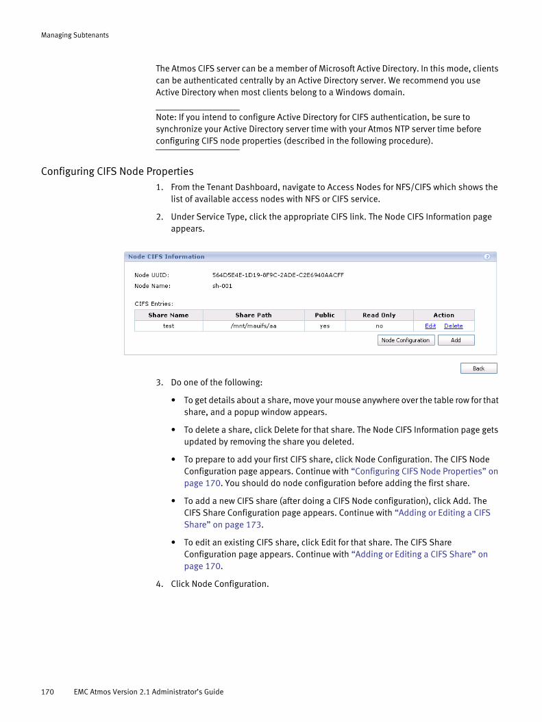
Managing Subtenants
The Atmos CIFS server can be a member of Microsoft Active Directory. In this mode, clients can be authenticated centrally by an Active Directory server. We recommend you use Active Directory when most clients belong to a Windows domain.
Note: If you intend to configure Active Directory for CIFS authentication, be sure to synchronize your Active Directory server time with your Atmos NTP server time before configuring CIFS node properties (described in the following procedure).
Configuring CIFS Node Properties1. From the Tenant Dashboard, navigate to Access Nodes for NFS/CIFS which shows the
list of available access nodes with NFS or CIFS service.
2. Under Service Type, click the appropriate CIFS link. The Node CIFS Information page appears.
3. Do one of the following:
• To get details about a share, move your mouse anywhere over the table row for that share, and a popup window appears.
• To delete a share, click Delete for that share. The Node CIFS Information page gets updated by removing the share you deleted.
• To prepare to add your first CIFS share, click Node Configuration. The CIFS Node Configuration page appears. Continue with “Configuring CIFS Node Properties” on page 170. You should do node configuration before adding the first share.
• To add a new CIFS share (after doing a CIFS Node configuration), click Add. The CIFS Share Configuration page appears. Continue with “Adding or Editing a CIFS Share” on page 173.
• To edit an existing CIFS share, click Edit for that share. The CIFS Share Configuration page appears. Continue with “Adding or Editing a CIFS Share” on page 170.
4. Click Node Configuration.
170 EMC Atmos Version 2.1 Administrator’s Guide
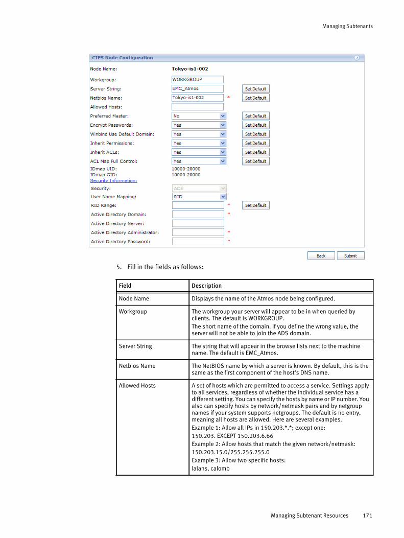
Managing Subtenants
5. Fill in the fields as follows:
Field Description
Node Name Displays the name of the Atmos node being configured.
Workgroup The workgroup your server will appear to be in when queried by clients. The default is WORKGROUP. The short name of the domain. If you define the wrong value, the server will not be able to join the ADS domain.
Server String The string that will appear in the browse lists next to the machine name. The default is EMC_Atmos.
Netbios Name The NetBIOS name by which a server is known. By default, this is the same as the first component of the host's DNS name.
Allowed Hosts A set of hosts which are permitted to access a service. Settings apply to all services, regardless of whether the individual service has a different setting. You can specify the hosts by name or IP number. You also can specify hosts by network/netmask pairs and by netgroup names if your system supports netgroups. The default is no entry, meaning all hosts are allowed. Here are several examples.Example 1: Allow all IPs in 150.203.*.*; except one:150.203. EXCEPT 150.203.6.66Example 2: Allow hosts that match the given network/netmask:150.203.15.0/255.255.255.0Example 3: Allow two specific hosts:lalans, calomb
Managing Subtenant Resources 171

Managing Subtenants
Preferred Master Controls the election of a master node in the CIFS domain and whether nmbd is a preferred master browser for its workgroup. (nmbd is a daemon service involved in the CIFS server. It queries the domain or share names in the domain.)Valid values are Yes, No, and Auto. If Yes, nmbd has a slight advantage in winning the election. If No, nmdb cannot win the election. If Auto, the election is random. The default is No.
Encrypt Passwords Specifies whether to encrypt CIFS user passwords. By default, Windows NT 4.0 SP3 and above and Windows 98 expect encrypted passwords. The default is Yes.
Winbind Use Default Domain
Specifies whether the winbindd daemon operates on users without a domain component in their usernames. Users without a domain component are treated as part of the winbindd server's own domain. The default is No.
Inherit Permissions When set to yes, create mask, directory mask, force create mode, and force directory mode are ignored. The normal behavior of setting the permissions on newly created files is overridden so that the new files and directories take on permissions from their parent directory. New directories will have exactly the same permissions as the parent, and new files will inherit the read and write bits from the parent directory, while the execute bits are determined as usual by the values of the map archive, map hidden, and map system parameters. If this option is set to yes, permissions on new files and directories are inherited from parent directory. The default value is no.
Inherit ACLs This parameter can be used to ensure that if default ACLs exist on parent directories, they are always honored when creating a new file or subdirectory in these parent directories. The default behavior is to use the UNIX mode specified when creating the directory. Enabling this option sets the UNIX mode to 0777, thus guaranteeing that default directory acls are propagated. The default value is yes.
ACL Map Full Control This parameter controls whether Samba maps an originating entry of rwx (read/write/execute) to FULL CONTROL in a Windows ACL. If set to Yes (default), this entry of rwx returns as FULL CONTROL in a Windows ACL. If set to No, this entry of rwx returns likewise but as corresponding bits in the Windows ACL.
IDmap UID The range of user IDs that are allocated for mapping UNIX users to NT user SIDs. This range of user IDs should not contain any existing local users; that is, it should be beyond the maximum UID value of the local system, to avoid overlapping.
IDmap GID The range of group IDs that are allocated for mapping UNIX groups to NT group SIDs. This range of group IDs should not contain any existing local groups; that is, it should be beyond the maximum GID value of the local system, to avoid overlapping.
Security Atmos supports only ADS mode.With ADS mode, the Atmos CIFS server can be a member of Microsoft Active Directory. In this mode, clients can be authenticated centrally by an Active Directory server. Atmos does not support: User (because Atmos does not support internal CIFS user management), Domain, and Share.
User Name Mapping By default, Atmos currently uses Active Directory Relative ID (RID) user mapping schema. This schema maps the RID of an object AD Security ID to a range specified in the CIFS configuration to provide a unique ID for a user/group. This schema is only valid for a Single Domain.
Field Description
172 EMC Atmos Version 2.1 Administrator’s Guide

Managing Subtenants
6. Click Submit.
The configuration fails unless your external servers’ times are synchronized with the Atmos NTP server time (see “Configuring NTP (Network Time Protocol)” on page 74. To ensure this, a dialog box appears with the following notice:
Is your Active Directory server time synchronized with your Atmos NTPserver time? If not, DO NOT PROCEED. See the Atmos documentation fordetails.
If your Active Directory server times are synchronized, click OK on the dialog, to return to the Node CIFS Information page. Otherwise, click Cancel on the dialog, to return to the CIFS Node Configuration page.
Adding or Editing a CIFS Share1. Login and navigate to the Access Nodes for NFS/CIFS area.
This lists the nodes available to the subtenant with the NFS or CIFS service defined.
RID Range Specifies the range of user/group IDs that are allocated for the purpose of mapping UNIX users to NT user RIDs. This range of user IDs should not contain any existing local users or groups; that is, it should be beyond the maximum UID value of the local system to avoid overlapping. A sample range is 20001 - 30000.
Active Directory Domain The fully qualified domain name of the database server. The Active Directory domain is used as the Active Directory service equivalent of the NT4 domain. This must be specified in all-capital letters.
Active Directory Server A directory service used to store information about the network resources. The Active Directory server is either an IP address or a simple host name.
Active Directory Administrator
The user name of the Active Directory administrator.
Active Directory Password The password of the Active Directory administrator.
Field Description
Managing Subtenant Resources 173

Managing Subtenants
2. Under Service Type, click the appropriate CIFS link. The CIFS Share Configuration page appears:
3. Edit the fields on the CIFS Share Configuration page. Parameters with red asterisks are required.
Field Description
Node Name Read-only field that displays the name of the node for which CIFS access is being configured.
Tenant Read-only field that displays the name of the tenant to which the node is assigned.
Subtenant Read-only field that displays the name of the subtenant. The CIFS share when created will map to this subtenant’s namespace.
Share Name Specify a string to display when a users attempt to map a drive to this Atmos node.
Share Path Specify the relative path name of the directory under /mnt/mauifs/ to share. Cannot include these characters: & < > ' or "
Note: This field does not support Unicode characters.
The resulting mount path depends on whether multi_subtenant_access is enabled or not. For example, if you specify share_path as testdir, and multi_subtenant_access is disabled, the resulting mount path is:
/mnt/mauifs/testdir
If multi_subtenant_access is enabled, the resulting path is:/mnt/mauifs/subtenantuuid/testdir
Public If Yes, no password is required to connect to the service; privileges are those of the guest account. The default is Yes.
Browseable Controls whether this share is seen in the list of available shares in a net view and in the browse list. The default is Yes.
174 EMC Atmos Version 2.1 Administrator’s Guide

Managing Subtenants
Read Only If Yes, users of the service cannot create or modify files in the service's directory. The default is No.
Comments This text field is seen next to a share when a client queries the server, either via the network neighborhood or via net view to list what shares are available.
Guest Only If Yes, only guest connections to the service are permitted. This parameter has no effect unless Public is set for the service. The default is Yes.
Valid Users A list of groups/users who are allowed to login to this service. If this is empty (the default), any user can login. Groups are specified using the @ symbol. To specify a group named Group1, you would enter @Group1. To specify a user named user1, you would enter user1. To specify both Group1 and User1, you would enter: @Group1, User1
Create Mask When a file is created, the necessary permissions are calculated according to the mapping from DOS modes to UNIX permissions, and the resulting UNIX mode is bit-wise AND-ed with this parameter. This parameter may be thought of as a bit-wise mask for a file’s UNIX access modes. Any bit not set here is removed from the modes set on a file when it is created. The default value of this parameter removes the “group” and “other” write and execute bits from the UNIX modes.
Directory Mask The octal modes used when converting DOS modes to UNIX modes when creating UNIX directories. When a directory is created, the necessary permissions are calculated according to the mapping from DOS modes to UNIX permissions, and the resulting UNIX mode is bit-wise AND-ed with this parameter. This parameter may be thought of as a bit-wise mask for a directory’s UNIX access modes. Any bit not set here is removed from the modes set on a directory when it is created. The default value of this parameter removes the “group” and “other” write bits from the UNIX mode, allowing only the user who owns the directory to modify it.
Write Cache Size
his option allows Samba to improve performance on systems where the disk subsystem is a bottleneck. The value of this option is specified in bytes, and a size of 262,144 represent a 256k cache size per file. The default Write Cache Size is 8,388,608 bytes.
Force Unknown ACL User
The ACLs that result on a Samba server will most probably not match the originating ACLs. Windows supports the possibility of files that are owned only by a group. Group-alone file ownership is not possible under UNIX/Linux. Errors in migrating group-owned files can be avoided by using the Force Unknown ACL User = yes parameter. This option will automatically convert group-owned files into correctly user-owned files on the Samba server.
Write List A list of groups/users who have read-write access to a service (comma separated). This option overrides the Read Only parameter. To specify a group named Group1, you would enter @Group1. To specify a user named user1, you would enter user1. To specify both Group1 and User1, you would enter: @Group1, User1
Field Description
Managing Subtenant Resources 175

Managing Subtenants
4. Click Submit. You return to the Node CIFS Information page.
Configuring NFS access nodes
Note: Before you configure NFS or CIFS access to Atmos, synchronize your external servers’ times with your Atmos NTP server time (see “Configuring the system master serial number” on page 74.
To configure NFS:
1. Navigate to the Access Nodes for NFS/CIFS area which shows the list of nodes with the NFS or CIFS service which can be accessed.
2. Under Service Type, click the appropriate NFS link. The Node NFS Information page appears.
3. To get details about a share, move your mouse anywhere over the table row for that share, and a popup window appears.
• To add a new NFS share, click Add.
• To edit an existing NFS share, click Edit.
• To remove the share, click Remove. This operations removes the specified NFS share path from the access node, but it does not remove any data from the share.
If you click Add or Edit, the NFS Configuration page appears.
Case-Sensitive This option allows case sensitivity to be enforced on file and folder names. If set to Yes (the default), file and folder names are case-sensitive which may increase performance on creates/writes (especially with small files). If set to No, file and folder names are not case-sensitive.
Field Description
176 EMC Atmos Version 2.1 Administrator’s Guide
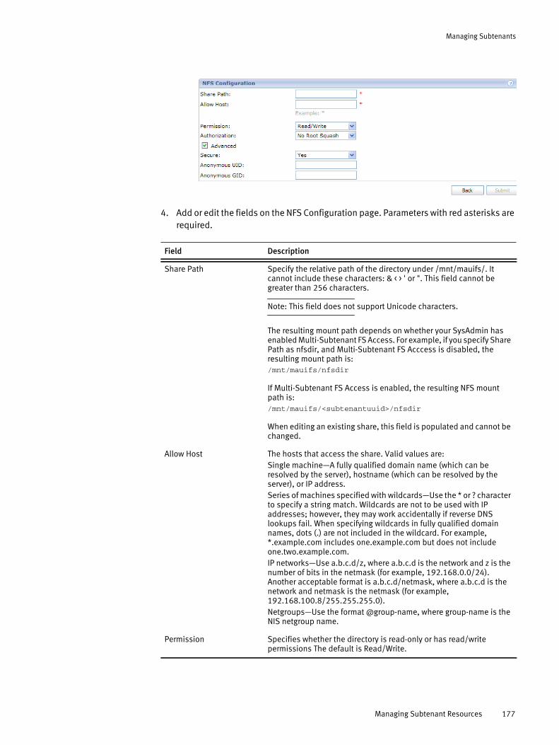
Managing Subtenants
4. Add or edit the fields on the NFS Configuration page. Parameters with red asterisks are required.
Field Description
Share Path Specify the relative path of the directory under /mnt/mauifs/. It cannot include these characters: & < > ' or ". This field cannot be greater than 256 characters.
Note: This field does not support Unicode characters.
The resulting mount path depends on whether your SysAdmin has enabled Multi-Subtenant FS Access. For example, if you specify Share Path as nfsdir, and Multi-Subtenant FS Acccess is disabled, the resulting mount path is: /mnt/mauifs/nfsdir
If Multi-Subtenant FS Access is enabled, the resulting NFS mount path is:/mnt/mauifs/<subtenantuuid>/nfsdir
When editing an existing share, this field is populated and cannot be changed.
Allow Host The hosts that access the share. Valid values are:Single machine—A fully qualified domain name (which can be resolved by the server), hostname (which can be resolved by the server), or IP address.Series of machines specified with wildcards—Use the * or ? character to specify a string match. Wildcards are not to be used with IP addresses; however, they may work accidentally if reverse DNS lookups fail. When specifying wildcards in fully qualified domain names, dots (.) are not included in the wildcard. For example, *.example.com includes one.example.com but does not include one.two.example.com.IP networks—Use a.b.c.d/z, where a.b.c.d is the network and z is the number of bits in the netmask (for example, 192.168.0.0/24). Another acceptable format is a.b.c.d/netmask, where a.b.c.d is the network and netmask is the netmask (for example, 192.168.100.8/255.255.255.0).Netgroups—Use the format @group-name, where group-name is the NIS netgroup name.
Permission Specifies whether the directory is read-only or has read/write permissions The default is Read/Write.
Managing Subtenant Resources 177
Managing Subtenants
Setting up CAS Policy-Driven StoragePrior to Atmos v2.1, only four CAS metadata tags were available for use in policy selectors to drive CAS storage. Beginning with Atmos v2.1, storage administrators can register their own tags as metadata tags or use 15 new CAS system metadata tags. Registering these tags promotes the tags to MDS, which makes the tags available for use in Atmos policy selectors.
Additionally, Atmos 2.1 allows storage administrators to completely control which tags are promoted to MDS. By default, no tags are promoted to MDS. Storage administrators must explicitly register all metadata tags they require for policy-driven storage.
CAS Administrator Tasks
Table 20 describes the administration tasks required to set up CAS policy-driven storage.
Authorization User access. Valid values are:all_squash—Treat all client users as anonymous users.root_squash—Do not treat a remote root user as local root.no_root_squash—Treat a remote root user as local root. This is the default.
Secure If Yes, requires that all requests originate from a port lower than 1024. If No, requests from any port number are accepted. The default is Yes.
Anonymous UID Sets the user ID of the anonymous account, to map all requests to one user.
Anonymous GID Sets the group ID of the anonymous account, to map all requests to one user.
Field Description
Table 20 CAS Administration Tasks
Task Documentation
Enable CAS access for an Atmos node Section “Assigning access nodes to a tenant” on page 104
Establish a CAS application: a combination of a Subtenant Id, UID, and shared secret
Section “Creating a UID and shared secret” on page 168
Register your CAS metadata tags for the application
Section “Registering Tags” on page 184
Generate a PEA file, which holds the access credentials for your CAS application
Section “Creating a PEA file for accessing Atmos CAS” on page 179
Understand CAS monitoring Section “Monitoring events” on page 140
178 EMC Atmos Version 2.1 Administrator’s Guide

Managing Subtenants
Creating a PEA file for accessing Atmos CAS
You can access Atmos CAS with the use of a PEA (Pool Entry Authorization) file. A PEA file contains the shared secret that is used to authenticate a subtenant ID and UID combination. CAS applications can optionally use a PEA file in the connection string to connect to a CAS-enabled access node. You create a PEA file with the Atmos-CAS PEA File Generator, a Java application that runs on your local machine.
Note: In Atmos, each PEA file can only contain a single set of access credentials.
To create a PEA file:
1. Download the Atmos-CAS PEA File Generator from http://Powerlink.EMC.comfollowing this path for registered users: Support > Software Downloads and Licensing > Downloads A-B > Atmos Software and Virtual Edition (VE).
2. Double-click the PEAGenerator.jar file to open the Atmos-CAS PEA file generator, as shown.
3. To get the information you need to complete the Atmos-CAS PEA File Generator dialog box, log in to Atmos using TenantAdmin.
4. From the Tenant Dashboard, record the Tenant ID.
5. In the Subtenant List area, click Edit next to the subtenant you want. At the Subtenant Information page, record the Subtenant ID.
6. In the UID List area, record the name and shared secret of the UID you want.
Setting up CAS Policy-Driven Storage 179
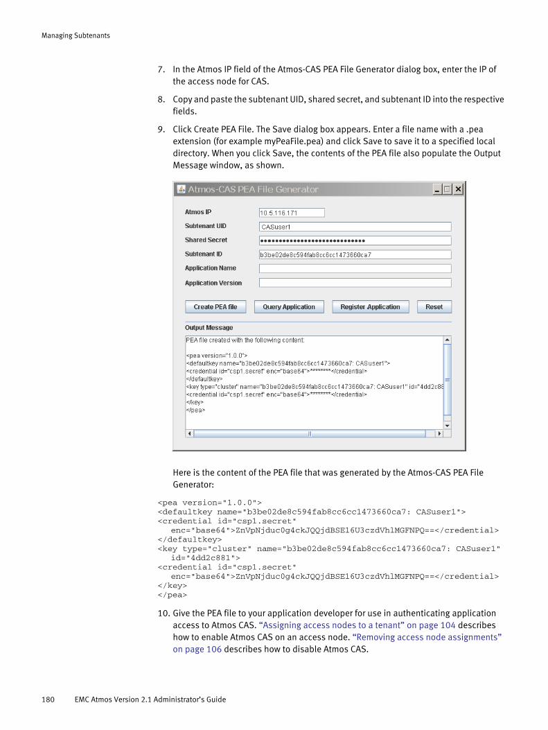
Managing Subtenants
7. In the Atmos IP field of the Atmos-CAS PEA File Generator dialog box, enter the IP of the access node for CAS.
8. Copy and paste the subtenant UID, shared secret, and subtenant ID into the respective fields.
9. Click Create PEA File. The Save dialog box appears. Enter a file name with a .pea extension (for example myPeaFile.pea) and click Save to save it to a specified local directory. When you click Save, the contents of the PEA file also populate the Output Message window, as shown.
Here is the content of the PEA file that was generated by the Atmos-CAS PEA File Generator:
<pea version="1.0.0"><defaultkey name="b3be02de8c594fab8cc6cc1473660ca7: CASuser1"><credential id="csp1.secret"
enc="base64">ZnVpNjduc0g4ckJQQjdBSE16U3czdVhlMGFNPQ==</credential></defaultkey><key type="cluster" name="b3be02de8c594fab8cc6cc1473660ca7: CASuser1"
id="4dd2c881"><credential id="csp1.secret"
enc="base64">ZnVpNjduc0g4ckJQQjdBSE16U3czdVhlMGFNPQ==</credential></key></pea>
10. Give the PEA file to your application developer for use in authenticating application access to Atmos CAS. “Assigning access nodes to a tenant” on page 104 describes how to enable Atmos CAS on an access node. “Removing access node assignments” on page 106 describes how to disable Atmos CAS.
180 EMC Atmos Version 2.1 Administrator’s Guide
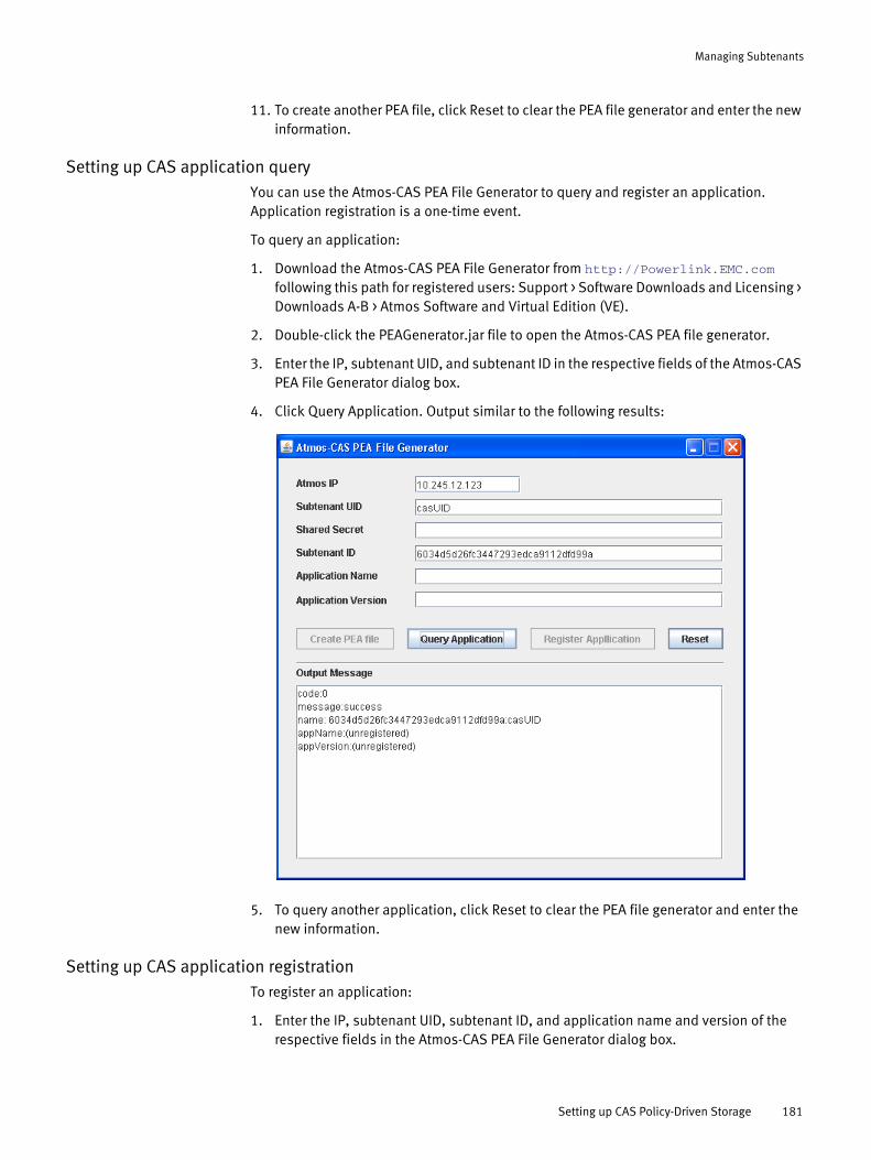
Managing Subtenants
11. To create another PEA file, click Reset to clear the PEA file generator and enter the new information.
Setting up CAS application queryYou can use the Atmos-CAS PEA File Generator to query and register an application. Application registration is a one-time event.
To query an application:
1. Download the Atmos-CAS PEA File Generator from http://Powerlink.EMC.comfollowing this path for registered users: Support > Software Downloads and Licensing > Downloads A-B > Atmos Software and Virtual Edition (VE).
2. Double-click the PEAGenerator.jar file to open the Atmos-CAS PEA file generator.
3. Enter the IP, subtenant UID, and subtenant ID in the respective fields of the Atmos-CAS PEA File Generator dialog box.
4. Click Query Application. Output similar to the following results:
5. To query another application, click Reset to clear the PEA file generator and enter the new information.
Setting up CAS application registrationTo register an application:
1. Enter the IP, subtenant UID, subtenant ID, and application name and version of the respective fields in the Atmos-CAS PEA File Generator dialog box.
Setting up CAS Policy-Driven Storage 181
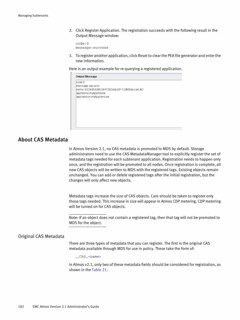
Managing Subtenants
2. Click Register Application. The registration succeeds with the following result in the Output Message window:
code:0message:success
3. To register another application, click Reset to clear the PEA file generator and enter the new information.
Here is an output example for re-querying a registered application.
About CAS Metadata
In Atmos Version 2.1, no CAS metadata is promoted to MDS by default. Storage administrators need to use the CAS MetadataManager tool to explicitly register the set of metadata tags needed for each subtenant application. Registration needs to happen only once, and the registration will be promoted to all nodes. Once registration is complete, all new CAS objects will be written to MDS with the registered tags. Existing objects remain unchanged. You can add or delete registered tags after the initial registration, but the changes will only affect new objects.
Metadata tags increase the size of CAS objects. Care should be taken to register only those tags needed. This increase in size will appear in Atmos CDP metering. CDP metering will be turned on for CAS objects.
Note: If an object does not contain a registered tag, then that tag will not be promoted to MDS for the object.
Original CAS MetadataThere are three types of metadata that you can register. The first is the original CAS metadata available through MDS for use in policy. These take the form of:
__CAS_<name>
In Atmos v2.1, only two of these metadata fields should be considered for registration, as shown in the Table 21.
182 EMC Atmos Version 2.1 Administrator’s Guide
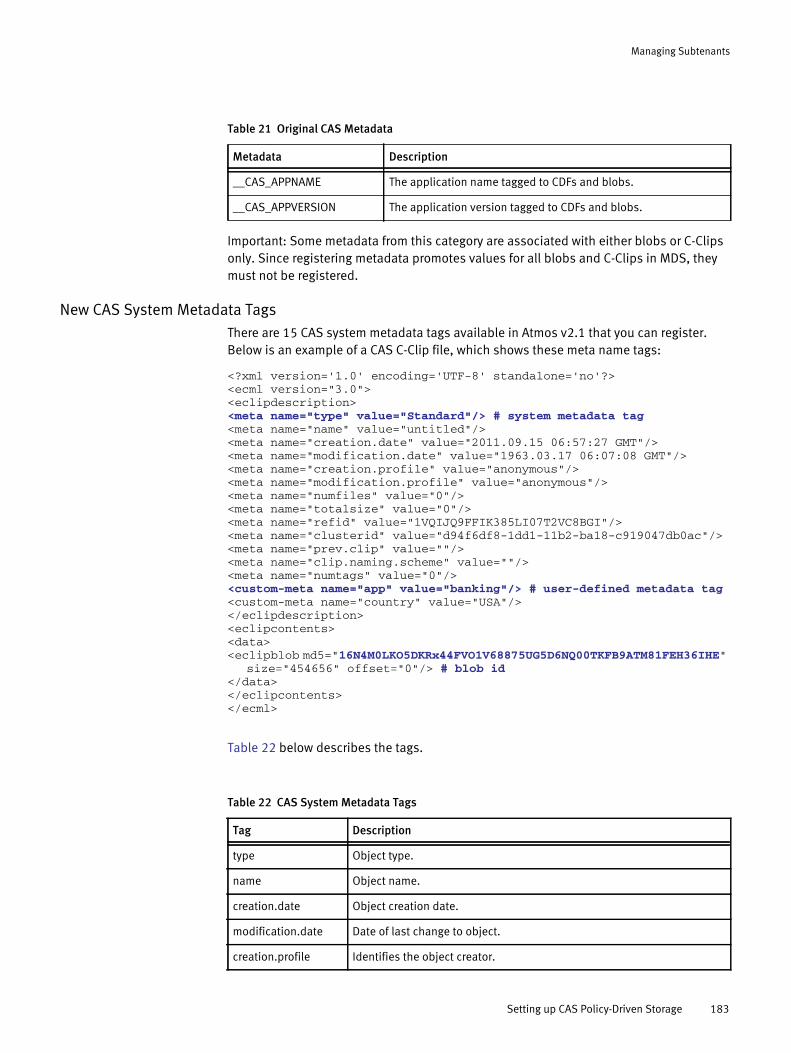
Managing Subtenants
Important: Some metadata from this category are associated with either blobs or C-Clips only. Since registering metadata promotes values for all blobs and C-Clips in MDS, they must not be registered.
New CAS System Metadata TagsThere are 15 CAS system metadata tags available in Atmos v2.1 that you can register. Below is an example of a CAS C-Clip file, which shows these meta name tags:
<?xml version='1.0' encoding='UTF-8' standalone='no'?><ecml version="3.0"><eclipdescription><meta name="type" value="Standard"/> # system metadata tag<meta name="name" value="untitled"/><meta name="creation.date" value="2011.09.15 06:57:27 GMT"/><meta name="modification.date" value="1963.03.17 06:07:08 GMT"/><meta name="creation.profile" value="anonymous"/><meta name="modification.profile" value="anonymous"/><meta name="numfiles" value="0"/><meta name="totalsize" value="0"/><meta name="refid" value="1VQIJQ9FFIK385LI07T2VC8BGI"/><meta name="clusterid" value="d94f6df8-1dd1-11b2-ba18-c919047db0ac"/><meta name="prev.clip" value=""/><meta name="clip.naming.scheme" value=""/><meta name="numtags" value="0"/><custom-meta name="app" value="banking"/> # user-defined metadata tag<custom-meta name="country" value="USA"/></eclipdescription><eclipcontents><data><eclipblob md5="16N4M0LKO5DKRx44FVO1V68875UG5D6NQ00TKFB9ATM81FEH36IHE"
size="454656" offset="0"/> # blob id</data></eclipcontents></ecml>
Table 22 below describes the tags.
Table 21 Original CAS Metadata
Metadata Description
__CAS_APPNAME The application name tagged to CDFs and blobs.
__CAS_APPVERSION The application version tagged to CDFs and blobs.
Table 22 CAS System Metadata Tags
Tag Description
type Object type.
name Object name.
creation.date Object creation date.
modification.date Date of last change to object.
creation.profile Identifies the object creator.
Setting up CAS Policy-Driven Storage 183
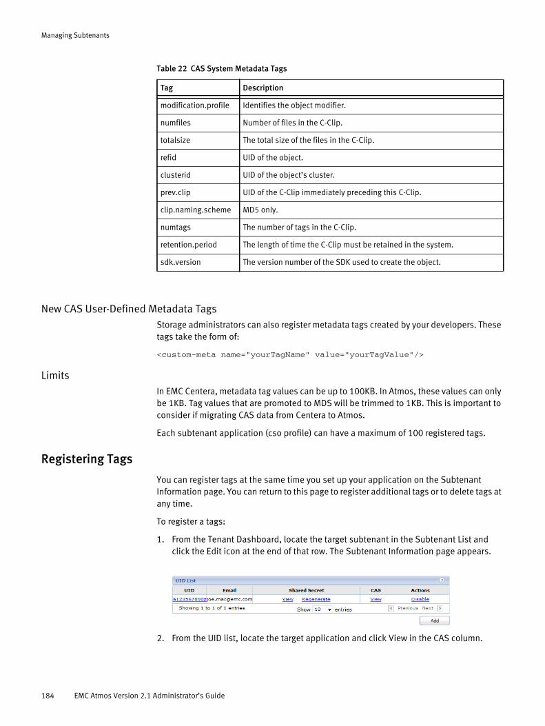
Managing Subtenants
New CAS User-Defined Metadata TagsStorage administrators can also register metadata tags created by your developers. These tags take the form of:
<custom-meta name="yourTagName" value="yourTagValue"/>
LimitsIn EMC Centera, metadata tag values can be up to 100KB. In Atmos, these values can only be 1KB. Tag values that are promoted to MDS will be trimmed to 1KB. This is important to consider if migrating CAS data from Centera to Atmos.
Each subtenant application (cso profile) can have a maximum of 100 registered tags.
Registering Tags
You can register tags at the same time you set up your application on the Subtenant Information page. You can return to this page to register additional tags or to delete tags at any time.
To register a tags:
1. From the Tenant Dashboard, locate the target subtenant in the Subtenant List and click the Edit icon at the end of that row. The Subtenant Information page appears.
2. From the UID list, locate the target application and click View in the CAS column.
modification.profile Identifies the object modifier.
numfiles Number of files in the C-Clip.
totalsize The total size of the files in the C-Clip.
refid UID of the object.
clusterid UID of the object’s cluster.
prev.clip UID of the C-Clip immediately preceding this C-Clip.
clip.naming.scheme MD5 only.
numtags The number of tags in the C-Clip.
retention.period The length of time the C-Clip must be retained in the system.
sdk.version The version number of the SDK used to create the object.
Table 22 CAS System Metadata Tags
Tag Description
184 EMC Atmos Version 2.1 Administrator’s Guide
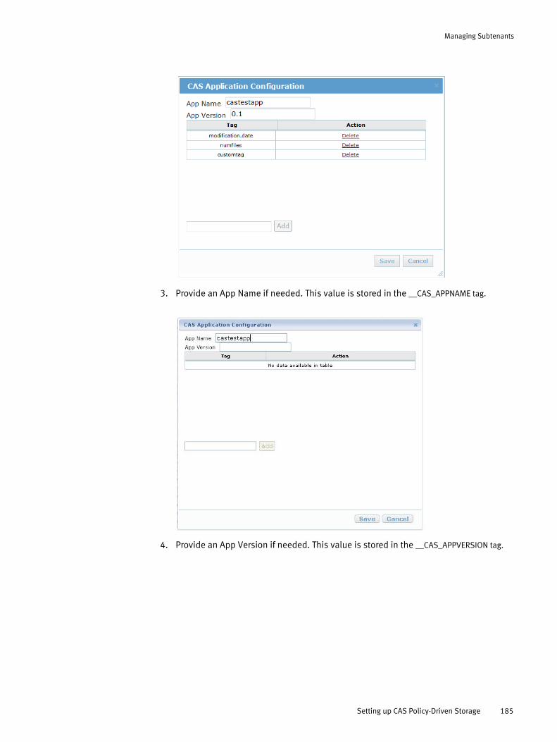
Managing Subtenants
3. Provide an App Name if needed. This value is stored in the __CAS_APPNAME tag.
4. Provide an App Version if needed. This value is stored in the __CAS_APPVERSION tag.
Setting up CAS Policy-Driven Storage 185
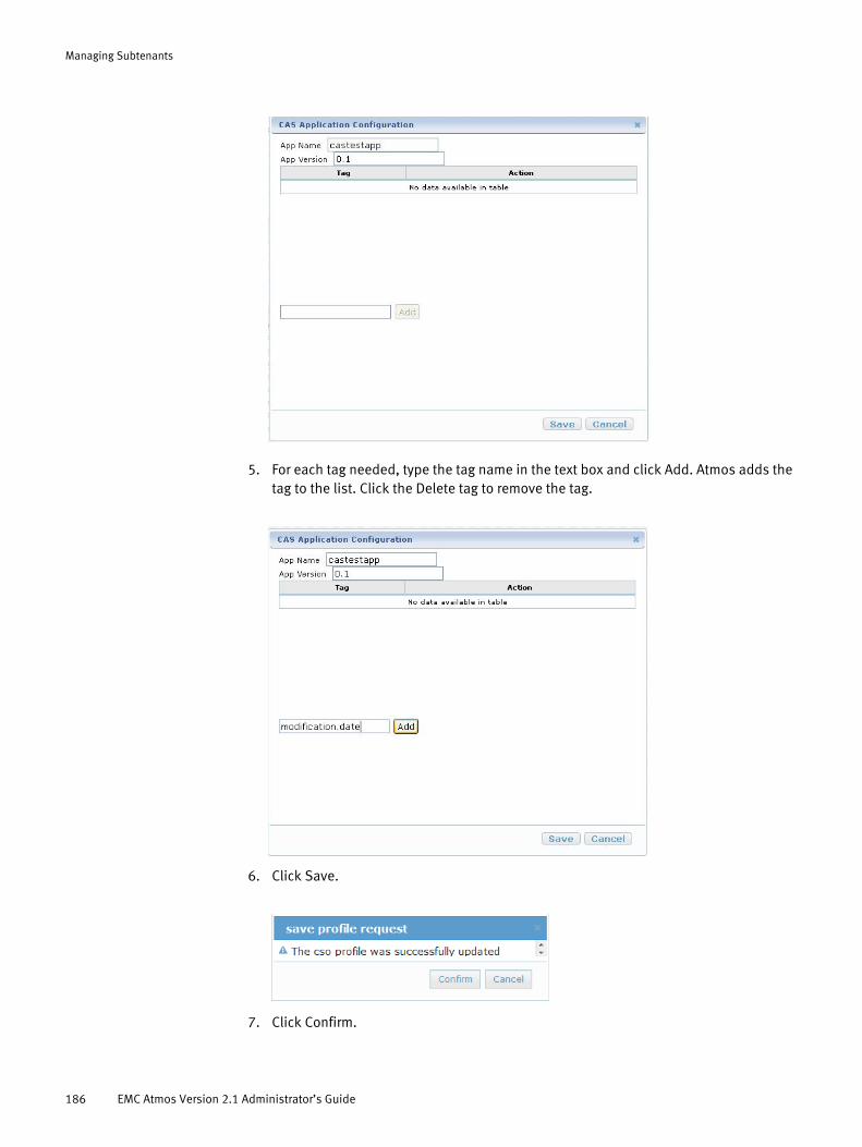
Managing Subtenants
5. For each tag needed, type the tag name in the text box and click Add. Atmos adds the tag to the list. Click the Delete tag to remove the tag.
6. Click Save.
7. Click Confirm.
186 EMC Atmos Version 2.1 Administrator’s Guide
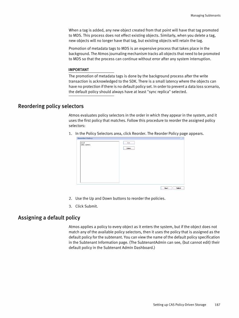
Managing Subtenants
When a tag is added, any new object created from that point will have that tag promoted to MDS. This process does not effect existing objects. Similarly, when you delete a tag, new objects will no longer have that tag, but existing objects will retain the tag.
Promotion of metadata tags to MDS is an expensive process that takes place in the background. The Atmos journaling mechanism tracks all objects that need to be promoted to MDS so that the process can continue without error after any system interruption.
IMPORTANT
The promotion of metadata tags is done by the background process after the write transaction is acknowledged to the SDK. There is a small latency where the objects can have no protection if there is no default policy set. In order to prevent a data loss scenario, the default policy should always have at least "sync replica" selected.
Reordering policy selectors
Atmos evaluates policy selectors in the order in which they appear in the system, and it uses the first policy that matches. Follow this procedure to reorder the assigned policy selectors:
1. In the Policy Selectors area, click Reorder. The Reorder Policy page appears.
2. Use the Up and Down buttons to reorder the policies.
3. Click Submit.
Assigning a default policy
Atmos applies a policy to every object as it enters the system, but if the object does not match any of the available policy selectors, then it uses the policy that is assigned as the default policy for the subtenant. You can view the name of the default policy specification in the Subtenant Information page. (The SubtenantAdmin can see, (but cannot edit) their default policy in the Subtenant Admin Dashboard.)
Setting up CAS Policy-Driven Storage 187
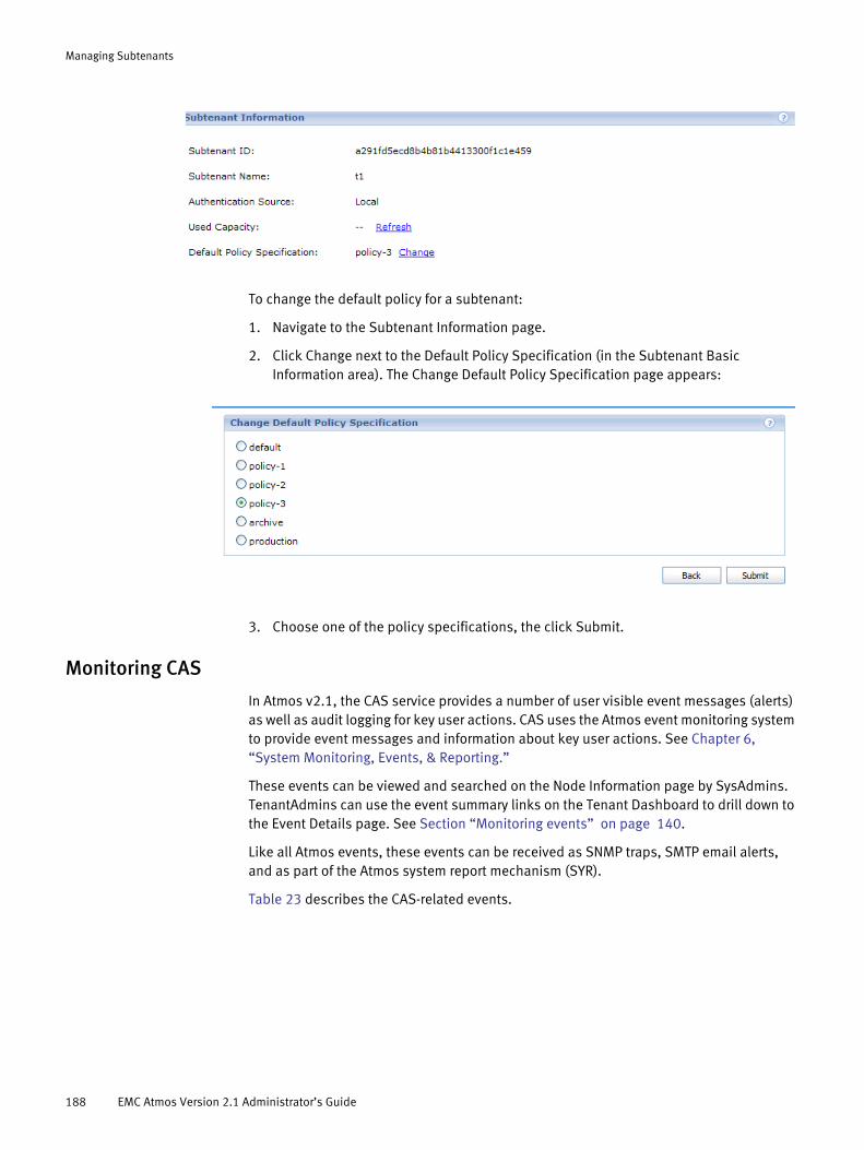
Managing Subtenants
To change the default policy for a subtenant:
1. Navigate to the Subtenant Information page.
2. Click Change next to the Default Policy Specification (in the Subtenant Basic Information area). The Change Default Policy Specification page appears:
3. Choose one of the policy specifications, the click Submit.
Monitoring CAS
In Atmos v2.1, the CAS service provides a number of user visible event messages (alerts) as well as audit logging for key user actions. CAS uses the Atmos event monitoring system to provide event messages and information about key user actions. See Chapter 6, “System Monitoring, Events, & Reporting.”
These events can be viewed and searched on the Node Information page by SysAdmins. TenantAdmins can use the event summary links on the Tenant Dashboard to drill down to the Event Details page. See Section “Monitoring events” on page 140.
Like all Atmos events, these events can be received as SNMP traps, SMTP email alerts, and as part of the Atmos system report mechanism (SYR).
Table 23 describes the CAS-related events.
188 EMC Atmos Version 2.1 Administrator’s Guide

Managing Subtenants
Note that the Information events are essentially CAS audit logging. These events are useful for C AS administrators investigating customer issues.
CAS troubleshooting
Authentication failure using LDAPIf you encounter "Authentication failure" trying to write CAS data with a regenerated shared secret when LDAP is configured as the keystore, you need to restart casd on all nodes.
In this scenario, casd is still recognizing the old shared secret. Restarting casd on the nodes will force the use of the new shared secret.
Table 23 CAS Events
Event ID Event Name SeverityEvent Text/Description
50022 Service Restarted Error CAS service has been restarted %d times in last %d %s. An additional attempt to restart CASD exceeds the threshold of %d times in %d %s.CASD fails to be restarted within expected attempts.
50023 Large Blob Unorphaning Queue Size Event
Error CAS blob unorphaning queue size (%d) exceeds the threshold (%d).Blob unorphaning queue size exceeds threshold.
50024 Large Blob Deletion Queue Size Event
Error CAS blob deletion queue size (%d) exceeds the threshold (%d).Blob deletion queue size exceeds threshold.
50025 Large Metadata Promotion Queue Size Event
Error CAS metadata promotion queue size (%d) exceeds threshold (%d)Metadata promotion queue size exceeds threshold.
01200 Enable/Disable CAS Service Information CAS access has been %s on this nodeCAS service has been enabled or disabled on this node.
01202 Enable/Disable CAS profile Information CAS profile (%s) has been %sCAS profile is enabled / disabled
01203 CAS Service Start/Stop Information CAS service has been manually %sCAS service has been manually stopped or started.
01204 CAS Metadata Promotion Set Change Event
Information CAS metadata promotion tag set has been changed.List of metadata tags to be promoted to MDS has changed. This event also occurs for application registration.
Setting up CAS Policy-Driven Storage 189

Managing Subtenants
190 EMC Atmos Version 2.1 Administrator’s Guide

CHAPTER 10Managing Policies
This chapter describes Atmos policy. It includes the following topics:
◆ About policy.......................................................................................................... 192◆ Working with policy specifications ........................................................................ 194◆ Working with policy selectors................................................................................ 203◆ Working with policy transition specifications ........................................................ 208◆ Policy example...................................................................................................... 217
Managing Policies 191
Managing Policies
About policyPolicy is a powerful feature that lets you define rules for data protection and data placement. Unlike traditional storage systems that apply policies at the volume or file system level, Atmos applies policies at the object level, and each object can have a different policy applied to it.
When a policy is applied to an object, Atmos automatically assigns the data services defined in the policy to the object. Atmos policies specify rules for:
◆ Object replication — You can define:
• How many replicas of an object should be created.
• Where the replicas should be located.
• How the replicas should be written (synchronously or asynchronously).
• Whether to compress or deduplicate the replicas.
• Whether to apply additional data protection (such as, striping or GeoParity).
◆ Object retention — You can define the amount of time during which an object cannot be deleted or modified.
◆ Object deletion — You can specify when an object will be removed from the system.
◆ Metadata location — You can specify the location where Atmos should store user and system metadata for new objects, files, or directories.
Atmos uses policies to implement information lifecycle management (ILM).
Atmos policy components
An Atmos policy is comprised of:
◆ A policy specification which defines how Atmos should replicate the object, and any retention or deletion rules. It also defines where Atmos should place metadata when the object is created. (A policy specification is only used if you assign it to a policy selector, or use it in a policy transition specification.)
◆ A policy selector which defines the conditions that cause a policy to be applied (triggered). You can create policy selectors for
• Object creates
• System metadata updates
• User metadata updates
Policy selectors are assigned to subtenants.
◆ (Optional) A policy transition specification which defines how objects transition through a set of policies over the object’s lifetime. A policy transition specification contains a set of policy specifications and the definitions for the conditions under which the object is moved to the next policy. Atmos supports age-based policy transitions.
192 EMC Atmos Version 2.1 Administrator’s Guide
Managing Policies
Note: If you are running Atmos LE, you are allowed to create a maximum of two policy specifications, or one policy transition specification.
Note: Policy definition is complex, so EMC recommends that you design your policies carefully and thoroughly before implementing them. Begin by familiarizing yourself with the information in this chapter so that you understand the design decisions.
When is a policy applied to an object?
Atmos always applies a policy to an object when the object is created, but you can also apply different policies to that object:
◆ When metadata changes — System or user metadata changes can occur when a REST, SOAP, or file-system application updates an object’s metadata.
◆ Automatically when age-based conditions are met — You can define how an object transitions through a set of policy specifications based on an amount of time that elapses after an object is created, modified, accessed, or after a policy is applied. For example, you could define a lifecycle that moves an object from a production policy to an archive policy six months after the object is created. This features is commonly referred to as automated ILM, and it is implemented through policy transition specifications.
Policy evaluation
The policies you create are valid only for data that enters the system through the nodes assigned to your tenant. You assign policy selectors to subtenants so you can create and assign unique policies for different subtenants.
Atmos evaluates the policy selectors in the order that they appear in the system. The first policy selector that matches the user or system metadata is applied to the object. The order of policy selectors can be changed using the Reorder button in the SubtenantAdmin dashboard.
When an object does not match any user-defined policy selector, Atmos applies the default policy specification.
Atmos evaluates age-based policy transition specifications once per 24 hour period (at midnight). This setting is not configurable.
About the default policy
Atmos creates a default policy specification, called default, for every tenant in the system. The default policy applies to all of the tenant’s subtenants. If no other policies are defined, Atmos applies the default policy to all objects as they enter the system. It also applies the default policy to all objects that do not match any user-defined policy selector.
The default policy is defined as:
◆ Two synchronous replicas. Both replicas are placed in the same location as the UID that created the object (using the symbol $clientCreateLoc).
◆ No server attribute constraints.
About policy 193

Managing Policies
You can modify the default policy, but you cannot delete it.
An Atmos system can operate with only the default policy.
You can also define a different policy specification to be the default for each subtenant that you manage. For more information, see “Assigning a default policy” on page 187.
Working with policy specificationsYou use the Policy Specification page, shown in Figure 22, to define:
◆ The policy specification name
◆ The location where Atmos should store the metadata
◆ Replica details such as:
• Replica write type — Sync or async.
Atmos recommends that your policy defines at least one sync replica
• Location — where to store the replica.
• Server attributes — what storage services to apply.
• Striping or Geoparity — Whether to apply either of these data protection mechanisms.
• Federation — Whether to export the data to an external cloud storage.
◆ Retention and deletion times
To access this page, log in to Atmos using your TenantAdmin credentials, then click Add in the Policy Specifications area.
Figure 22 Policy specification page
A policy specification cannot be deleted if it is referenced by a policy selector or by a policy transition, or if it is assigned as the default policy for a subtenant.
194 EMC Atmos Version 2.1 Administrator’s Guide
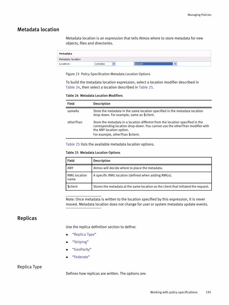
Managing Policies
Metadata location
Metadata location is an expression that tells Atmos where to store metadata for new objects, files and directories.
Figure 23 Policy Specification Metadata Location Options
To build the metadata location expression, select a location modifier described in Table 24, then select a location described in Table 25.
Table 25 lists the available metadata location options.
Note: Once metadata is written to the location specified by this expression, it is never moved. Metadata location does not change for user or system metadata update events.
Replicas
Use the replica definition section to define:
◆ “Replica Type”
◆ “Striping”
◆ “GeoParity”
◆ “Federate”
Replica TypeDefines how replicas are written. The options are:
Table 24 Metadata Location Modifiers
Field Description
sameAs Store the metadata in the same location specified in the metadata location drop-down. For example, same as $client.
otherThan Store the metadata in a location different from the location specified in the corresponding location drop-down. You cannot use the otherThan modifier with the ANY location option.For example, otherThan $client.
Table 25 Metadata Location Options
Field Description
ANY Atmos will decide where to place the metadata.
RMG location name
A specific RMG location (defined when adding RMGs).
$client Stores the metadata at the same location as the client that initiated the request.
Working with policy specifications 195

Managing Policies
◆ Sync — (the default). In general, sync replicas are bit-for-bit copies that are identical at any point in time. If one or more sync replicas are not accessible (possibly because of a disk failure), Atmos will acknowledge the write to the application when the available sync replicas are committed. It will temporarily exclude the inaccessible replica(s) from the list of sync replicas, and schedule it for background repair.
At least one sync replica must be successfully written to in order for Atmos to acknowledge a write.
◆ Async — Async replication is done on a best-effort basis. Atmos uses the eventual consistency model so updates are made eventually, but it does not guarantee when that occurs.
A single object can have both synchronous and asynchronous replicas.
LocationThe location specification tells Atmos where to write the replica. You should plan your replication strategy so that replica locations ensure both:
◆ Data availability — Put some copies of the data close to where it will be accessed.
◆ Data protection — Put replicas in different locations to protect against disk failures.
To build the location expression, select a location modifier (described in Table 26) and a location (described in Table 27).
Table 26 Location modifier options
Field Description
sameAs Store the replica in the location specified in the location dropdown.For example, sameAs Tokyo.
otherThan Store the replica in a different location than is specified in the location dropdown. However, otherThan does not enable you to specify which other location should be used.For example, otherThan Tokyo.
196 EMC Atmos Version 2.1 Administrator’s Guide
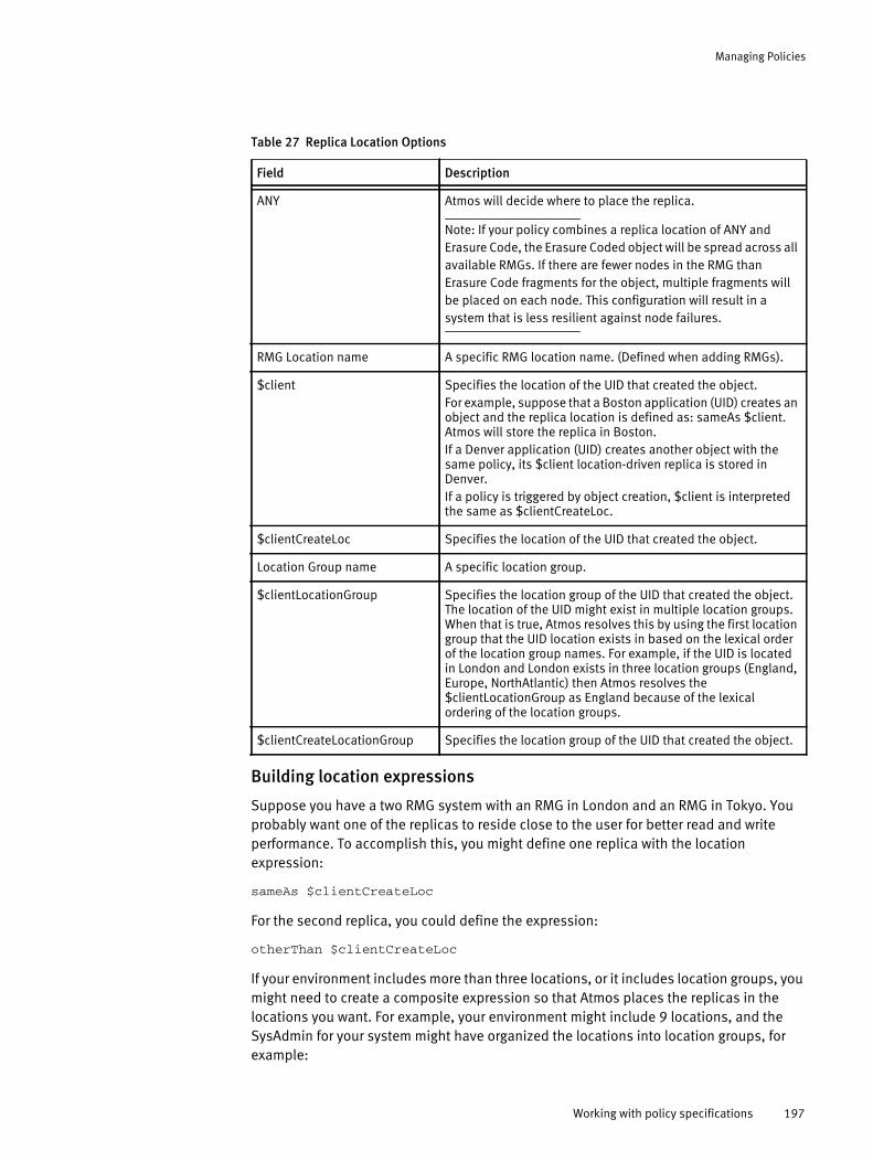
Managing Policies
Building location expressions
Suppose you have a two RMG system with an RMG in London and an RMG in Tokyo. You probably want one of the replicas to reside close to the user for better read and write performance. To accomplish this, you might define one replica with the location expression:
sameAs $clientCreateLoc
For the second replica, you could define the expression:
otherThan $clientCreateLoc
If your environment includes more than three locations, or it includes location groups, you might need to create a composite expression so that Atmos places the replicas in the locations you want. For example, your environment might include 9 locations, and the SysAdmin for your system might have organized the locations into location groups, for example:
Table 27 Replica Location Options
Field Description
ANY Atmos will decide where to place the replica.
Note: If your policy combines a replica location of ANY and Erasure Code, the Erasure Coded object will be spread across all available RMGs. If there are fewer nodes in the RMG than Erasure Code fragments for the object, multiple fragments will be placed on each node. This configuration will result in a system that is less resilient against node failures.
RMG Location name A specific RMG location name. (Defined when adding RMGs).
$client Specifies the location of the UID that created the object. For example, suppose that a Boston application (UID) creates an object and the replica location is defined as: sameAs $client. Atmos will store the replica in Boston. If a Denver application (UID) creates another object with the same policy, its $client location-driven replica is stored in Denver.If a policy is triggered by object creation, $client is interpreted the same as $clientCreateLoc.
$clientCreateLoc Specifies the location of the UID that created the object.
Location Group name A specific location group.
$clientLocationGroup Specifies the location group of the UID that created the object. The location of the UID might exist in multiple location groups. When that is true, Atmos resolves this by using the first location group that the UID location exists in based on the lexical order of the location group names. For example, if the UID is located in London and London exists in three location groups (England, Europe, NorthAtlantic) then Atmos resolves the $clientLocationGroup as England because of the lexical ordering of the location groups.
$clientCreateLocationGroup Specifies the location group of the UID that created the object.
Working with policy specifications 197
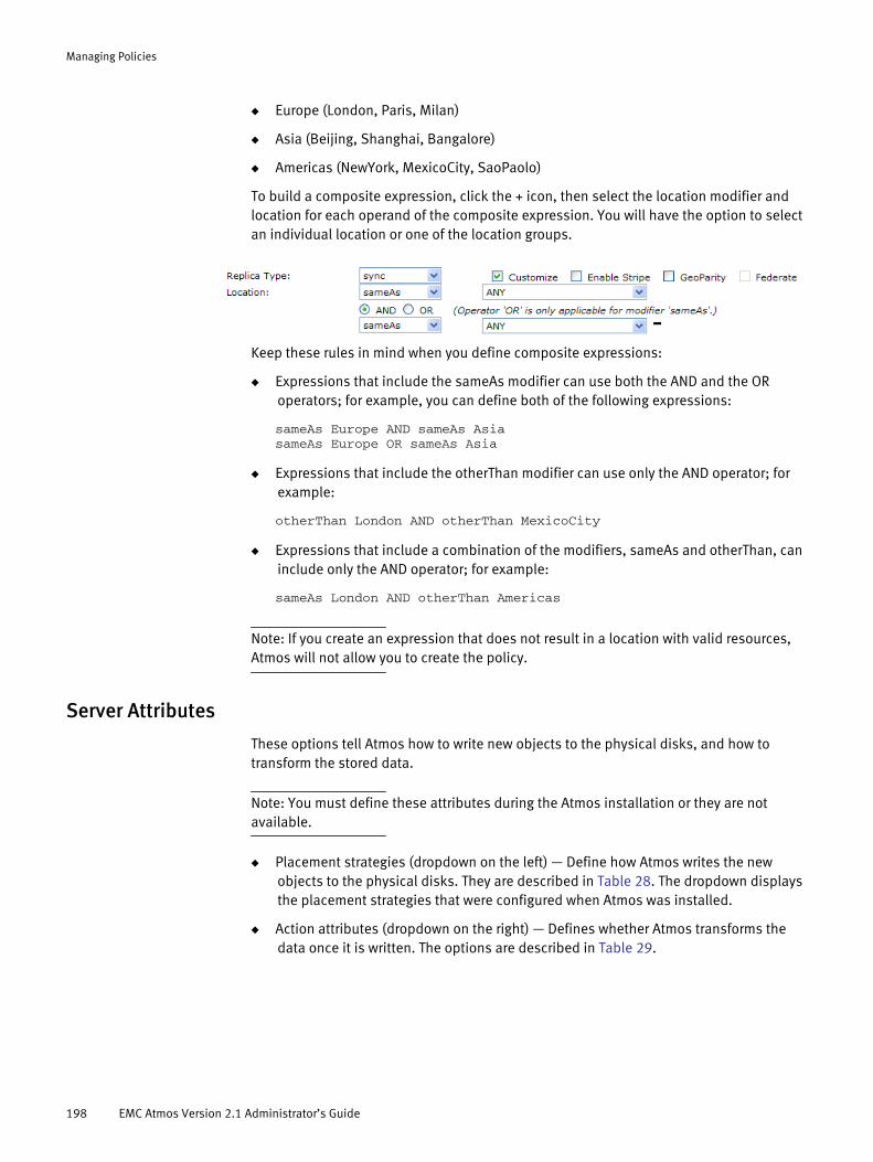
Managing Policies
◆ Europe (London, Paris, Milan)
◆ Asia (Beijing, Shanghai, Bangalore)
◆ Americas (NewYork, MexicoCity, SaoPaolo)
To build a composite expression, click the + icon, then select the location modifier and location for each operand of the composite expression. You will have the option to select an individual location or one of the location groups.
Keep these rules in mind when you define composite expressions:
◆ Expressions that include the sameAs modifier can use both the AND and the OR operators; for example, you can define both of the following expressions:
sameAs Europe AND sameAs AsiasameAs Europe OR sameAs Asia
◆ Expressions that include the otherThan modifier can use only the AND operator; for example:
otherThan London AND otherThan MexicoCity
◆ Expressions that include a combination of the modifiers, sameAs and otherThan, can include only the AND operator; for example:
sameAs London AND otherThan Americas
Note: If you create an expression that does not result in a location with valid resources, Atmos will not allow you to create the policy.
Server Attributes
These options tell Atmos how to write new objects to the physical disks, and how to transform the stored data.
Note: You must define these attributes during the Atmos installation or they are not available.
◆ Placement strategies (dropdown on the left) — Define how Atmos writes the new objects to the physical disks. They are described in Table 28. The dropdown displays the placement strategies that were configured when Atmos was installed.
◆ Action attributes (dropdown on the right) — Defines whether Atmos transforms the data once it is written. The options are described in Table 29.
198 EMC Atmos Version 2.1 Administrator’s Guide
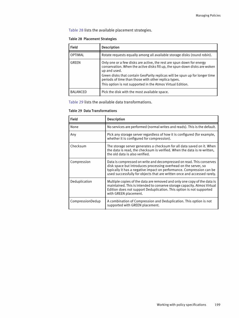
Managing Policies
Table 28 lists the available placement strategies.
Table 29 lists the available data transformations.
Table 28 Placement Strategies
Field Description
OPTIMAL Rotate requests equally among all available storage disks (round robin).
GREEN Only one or a few disks are active, the rest are spun down for energy conservation. When the active disks fill up, the spun-down disks are woken up and used. Green disks that contain GeoParity replicas will be spun up for longer time periods of time than those with other replica types. This option is not supported in the Atmos Virtual Edition.
BALANCED Pick the disk with the most available space.
Table 29 Data Transformations
Field Description
None No services are performed (normal writes and reads). This is the default.
Any Pick any storage server regardless of how it is configured (for example, whether it is configured for compression).
Checksum The storage server generates a checksum for all data saved on it. When the data is read, the checksum is verified. When the data is re-written, the old data is also verified.
Compression Data is compressed on write and decompressed on read. This conserves disk space but introduces processing overhead on the server, so typically it has a negative impact on performance. Compression can be used successfully for objects that are written once and accessed rarely.
Deduplication Multiple copies of the data are removed and only one copy of the data is maintained. This is intended to conserve storage capacity. Atmos Virtual Edition does not support Deduplication. This option is not supported with GREEN placement.
CompressionDedup A combination of Compression and Deduplication. This option is not supported with GREEN placement.
Working with policy specifications 199

Managing Policies
Striping
Striping enables you to put blocks of data of the same replica on different nodes. The Enable Stripe options are shown in Figure 24.
Figure 24 Policy Specification Enable Stripe Options
Table 30 lists the striping options.
GeoParity
GeoParity provides data redundancy without the overhead of replication. GeoParity divides an object into rows, each of which consists of m data fragments and k coding fragments. Each fragment of each row is then stored on a different disk. The disks that compose a Geoparity replica are also called columns of the replica. Using this method, a given row of the replica can be reconstructed from any m of the fragments in the row. Thus the replica can tolerate the unavailability of up to k fragments without losing the contents of the row.
For a GeoParity replica that spans locations:
◆ Columns will be distributed as evenly as possible across the locations. That is, each location will contain either C or C + 1 columns of each replica.
◆ Within each location the columns at this location will be distributed as evenly as possible across the eligible storage services at this location.
Table 30 Striping Options
Field Description
Stripe Number Number of nodes to stripe across.
Stripe Size Amount of data written to each node.
Stripe Unit Options are B, KB, MB, GB, and TB.
200 EMC Atmos Version 2.1 Administrator’s Guide
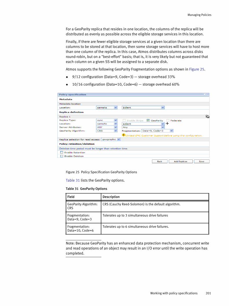
Managing Policies
For a GeoParity replica that resides in one location, the columns of the replica will be distributed as evenly as possible across the eligible storage services in this location.
Finally, if there are fewer eligible storage services at a given location than there are columns to be stored at that location, then some storage services will have to host more than one column of the replica. In this case, Atmos distributes columns across disks round-robin, but on a "best-effort" basis; that is, it is very likely but not guaranteed that each column on a given SS will be assigned to a separate disk.
Atmos supports the following GeoParity Fragmentation options as shown in Figure 25.
◆ 9/12 configuration (Data=9, Code=3) — storage overhead 33%
◆ 10/16 configuration (Data=10, Code=6) — storage overhead 60%
Figure 25 Policy Specification GeoParity Options
Table 31 lists the GeoParity options.
Note: Because GeoParity has an enhanced data protection mechanism, concurrent write and read operations of an object may result in an I/O error until the write operation has completed.
Table 31 GeoParity Options
Field Description
GeoParity Algorithm: CRS
CRS (Cauchy Reed-Solomon) is the default algorithm.
Fragmentation: Data=9, Code=3
Tolerates up to 3 simultaneous drive failures
Fragmentation: Data=10, Code=6
Tolerates up to 6 simultaneous drive failures.
Working with policy specifications 201
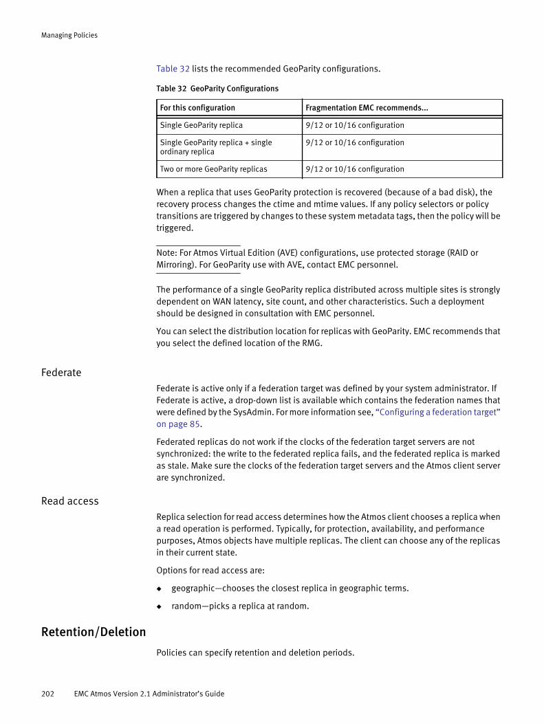
Managing Policies
Table 32 lists the recommended GeoParity configurations.
When a replica that uses GeoParity protection is recovered (because of a bad disk), the recovery process changes the ctime and mtime values. If any policy selectors or policy transitions are triggered by changes to these system metadata tags, then the policy will be triggered.
Note: For Atmos Virtual Edition (AVE) configurations, use protected storage (RAID or Mirroring). For GeoParity use with AVE, contact EMC personnel.
The performance of a single GeoParity replica distributed across multiple sites is strongly dependent on WAN latency, site count, and other characteristics. Such a deployment should be designed in consultation with EMC personnel.
You can select the distribution location for replicas with GeoParity. EMC recommends that you select the defined location of the RMG.
FederateFederate is active only if a federation target was defined by your system administrator. If Federate is active, a drop-down list is available which contains the federation names that were defined by the SysAdmin. For more information see, “Configuring a federation target” on page 85.
Federated replicas do not work if the clocks of the federation target servers are not synchronized: the write to the federated replica fails, and the federated replica is marked as stale. Make sure the clocks of the federation target servers and the Atmos client server are synchronized.
Read accessReplica selection for read access determines how the Atmos client chooses a replica when a read operation is performed. Typically, for protection, availability, and performance purposes, Atmos objects have multiple replicas. The client can choose any of the replicas in their current state.
Options for read access are:
◆ geographic—chooses the closest replica in geographic terms.
◆ random—picks a replica at random.
Retention/Deletion
Policies can specify retention and deletion periods.
Table 32 GeoParity Configurations
For this configuration Fragmentation EMC recommends...
Single GeoParity replica 9/12 or 10/16 configuration
Single GeoParity replica + single ordinary replica
9/12 or 10/16 configuration
Two or more GeoParity replicas 9/12 or 10/16 configuration
202 EMC Atmos Version 2.1 Administrator’s Guide

Managing Policies
◆ Retention — A period of time during which the object cannot be modified or deleted. Atmos evaluates the retention period based on the object create time. If retention is applied when the object is created, you must also specify a Start Delay Window. The Start Delay Window specifies the amount of time to wait before applying the retention period. Once the retention period has passed, then the user can update the object. You can apply a new retention period (after the first one has elapsed), but the time evaluation will continue to be based on the object’s create time.
◆ Deletion — The time after an object was created that it should be deleted. This time must be longer than the retention time since it is not possible to delete an object that is being retained. Deletion applies only to files, not directories. The retention and deletion fields are shown in Figure 26.
Figure 26 Policy Specification Retention and Deletion Options
Note: While objects might expire at various times during the day when their deletion period is met, Atmos purges these expired objects once a day.
Working with policy selectorsA policy selector is an expression that causes a policy specification to be applied to an object when the selector expression conditions are met. The conditions are typically defined based on user or system metadata changes.
Working with policy selectors 203
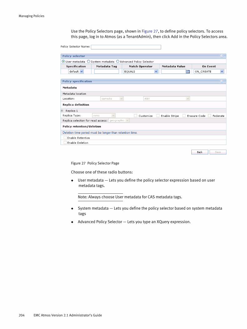
Managing Policies
Use the Policy Selectors page, shown in Figure 27, to define policy selectors. To access this page, log in to Atmos (as a TenantAdmin), then click Add in the Policy Selectors area.
Figure 27 Policy Selector Page
Choose one of these radio buttons:
◆ User metadata — Lets you define the policy selector expression based on user metadata tags.
Note: Always choose User metadata for CAS metadata tags.
◆ System metadata — Lets you define the policy selector based on system metadata tags
◆ Advanced Policy Selector — Lets you type an XQuery expression.
204 EMC Atmos Version 2.1 Administrator’s Guide

Managing Policies
Table 33 describes the policy selector fields.
Table 33 Policy Selector Fields
Field Description
Specification Choose the name of the policy specification or the policy transition specification to apply to the objects when the policy selector conditions are met.
Metadata Tag Enter or choose a metadata tag for the first operand in the policy selector expression. System metadata tags include:• atime — last access time• mtime — last modified time• ctime — change time• itime — create time• uid — UID from UID List, where you create new applications from• gid — group ID, N/A to Web Service users; ignore• size — object size in bytes. This metadata is NOT available for 'ON_CREATE' event.• objname — N/A to Web Service users this release; ignoreThe time format for atime, mtime, ctime, itime is as follows: YYYY-MM-DDTHH:MnMn:SSZ Where: YYYY = Year, MM = Month, DD = Day, HH = Hour, MnMn = Minutes, SS = Seconds. Note that there is a T in between DD and HH, and also a Z at the end. For example, April 12, 2008 at 3:35 would be displayed as:2008-04-12T03:45:00Z
Match Operator Choose an operator to use in the selector expression. The following operators are available:• Equals — matches the defined entry• Starts With — starts with the defined entry• Ends With — ends with the defined entry• Contains — contains the defined entry• < — less than the defined entry• = — equals the defined entry• > — greater than the defined entry• <= — less than or equal to the defined entry• >= — greater than or equal to the defined entry
Working with policy selectors 205

Managing Policies
Triggering On_CREATE based on object sizeAtmos prevents you from using the ON_CREATE event and the system metadata size option because Atmos creates objects with a system metadata size of 0 bytes. However, you can still trigger ON_CREATE based on object size using the user metadata reserved tag called x-maui-create-size.
This example shows how you could define a policy selector for objects over 1000000 bytes at create time:
Figure 28 On_Create with user metadata size
Using the Linux touch commandIf you use the Linux touch command to create a file, it will cause an ON_CREATE event followed by an ON_SMD_UPDATE event to occur. Atmos complies with the POSIX behavior of the touch command. Internally, it performs the following steps:
1. Determine if the object exists.
Metadata Value Enter or choose a metadata value as the second operand in the policy selector expression.
XQuery Expression Enter the XQuery expression that will be used to determine which policy is applied to the object. For example, a query for all objects of .jpg file type would have the following expression://objname[ends-with(.,'.jpg')]
On Event Choose the event that triggers the policy selector. The following object events cause evaluation of policies on existing objects:• ON_CREATE — This event is triggered when an object matching this definition is
created.• ON_SMD_UPDATE— This event is triggered when a change in the system metadata of
an object is made. System metadata includes: atime, mtime, ctime, uid, gid, mode, ACL, DACL, expiration time, and retention time (ACL, expiration time, and retention time are extended attributes available in the Atmos reserved namespace). Policy evaluation is only triggered when attributes are changed directly (for example, through commands, such as chmod, chown, and truncate), or by REST operations that change object ACLs. Policy evaluation is not triggered by indirect operations, such as modifying the data. System metadata changes caused by REST data operations, such as, extending the length of an object, do not trigger policy evaluation.Note that for write operations through CIFS/Samba, the Samba server calls the utime subroutine to change the modification and access times of the file touched, which will trigger policy evaluation.
• ON_UMD_UPDATE — This event is triggered when a change in the user metadata of an object is made.
Note: For CAS policies, always select ON_UMD_UPDATE. This event is triggered when a change in the user metadata of an object is made.
Table 33 Policy Selector Fields (continued)
Field Description
206 EMC Atmos Version 2.1 Administrator’s Guide

Managing Policies
2. If the object does not exist, then create it.
3. Open the object.
4. Update the object.
5. Close the object.
In this workflow, if you have defined a policy selector for the ON_CREATE event, it will fire during the Step 2, and it will apply the associated policy specification. If you also have a policy selector defined for the ON_SMD_UPDATE event, and the object’s system metadata satisfies the criteria for the ON_SMD_UPDATE policy selector, it will be triggered in Step 4. For this reason, if you plan to use the Linux touch command to create files, plan your policy selector strategy carefully.
Using CAS metadata tags to define policiesYou can create a policy selector that is specifically designed to define policies for CAS data. Atmos CAS applies user metadata tags to CAS objects during write creation. These tags can be used to differentiate CAS objects from non-CAS objects; and among CAS objects, CDFs from blobs.
In the Policy selector area of the Policy Selector Name page, you select User metadata and fill in the Metadata Tag and Metadata Value fields. Table 34 lists the tags you can use to define policies for CAS objects. Each tag type relates to a certain part of the object.
Assigning policy selectors to subtenants
Once you define the policy selector, you need to assign it to a subtenant. If a policy selector is not assigned, Atmos will not use it.
Table 34 CAS metadata tags
User metadata tag How used
_CSO_ISCDF Tagged to CDFs only.
_CSO_APPNAME The application name tagged to CDFs and blobs.
Note: To enable Atmos CAS to tag the application name, you must first register the application name that is associated with the combined subtenant UID and subtenant ID pair. Use the Atmos-CAS PEA File Generator to do the one-time application registration.
_CSO_APPVERSION The application version tagged to CDFs and blobs.
Note: To enable Atmos CAS to tag the application version, you must first register the application version that is associated with the combined subtenant UID and subtenant ID pair. Use the Atmos-CAS PEA File Generator to do the one-time application registration.
_CSO_ORPHANED_BLOB Tagged to blobs only. Orphan blobs exist if an application writes blobs without writing the associated CDFs.
Working with policy selectors 207

Managing Policies
To assign a policy selector to a subtenant:
1. Navigate to the Policy Selectors section of the Tenant Dashboard.
2. Click the Assign icon. The Assign Policy page appears.
3. Select the check box for the subtenant to which you want to assign the policy, then click Submit.
Working with policy transition specificationsA policy transition specification represents an information lifecycle storage strategy for an object. Within a policy transition specification, you define:
◆ A start policy — This is the policy that is applied to the object before it begins the age-based transitions.
◆ One or more policy specifications and the conditions that cause the object to transition from one policy to the next.
Objects that are associated with a policy transition specification are moved from one policy to the next automatically when a certain condition is met. For this release, Atmos supports age-based conditions. Figure 29 illustrates how an object governed by a policy transition specification would move from Policy1 through PolicyN (the object’s final state).
In addition, an object can move in and out of the policy transition specification. For example, a policy selector might be triggered that moves the object to a policy that is not part of the policy transition specification.
Figure 29 Policy transitions
208 EMC Atmos Version 2.1 Administrator’s Guide
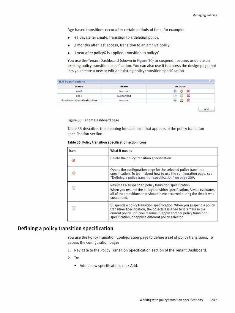
Managing Policies
Age-based transitions occur after certain periods of time, for example:
◆ 45 days after create, transition to a deletion policy.
◆ 3 months after last access, transition to an archive policy.
◆ 1 year after policyX is applied, transition to policyY
You use the Tenant Dashboard (shown in Figure 30) to suspend, resume, or delete an existing policy transition specification. You can also use it to access the design page that lets you create a new or edit an existing policy transition specification.
Figure 30 Tenant Dashboard page
Table 35 describes the meaning for each icon that appears in the policy transition specification section.
Defining a policy transition specification
You use the Policy Transition Configuration page to define a set of policy transitions. To access the configuration page:
1. Navigate to the Policy Transition Specification section of the Tenant Dashboard.
2. To:
• Add a new specification, click Add.
Table 35 Policy transition specification action Icons
Icon What it means
Delete the policy transition specification.
Opens the configuration page for the selected policy transition specification. To learn about how to use the configuration page, see “Defining a policy transition specification” on page 209.
Resumes a suspended policy transition specification.When you resume the policy transition specification, Atmos evaluates all of the transitions that should have occurred during the time it was suspended.
Suspends a policy transition specification. When you suspend a policy transition specification, the objects assigned to it remain in the current policy until you resume it, apply another policy transition specification, or apply a different policy selector.
Working with policy transition specifications 209
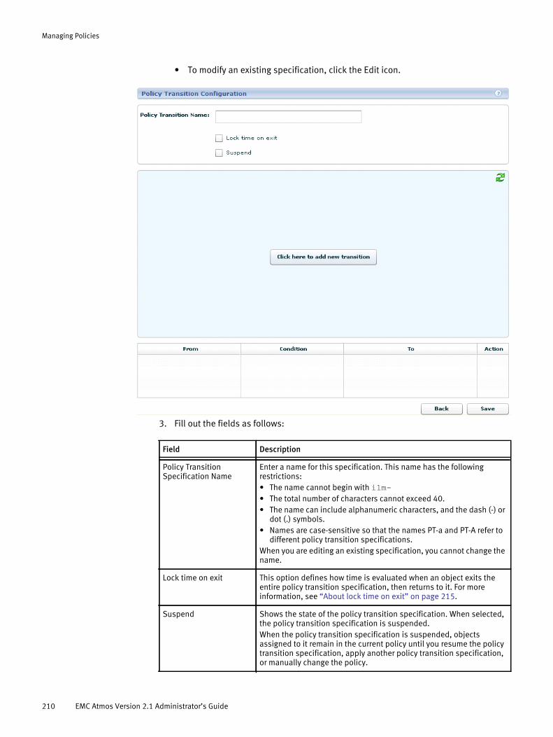
Managing Policies
• To modify an existing specification, click the Edit icon.
3. Fill out the fields as follows:
Field Description
Policy Transition Specification Name
Enter a name for this specification. This name has the following restrictions: • The name cannot begin with ilm-• The total number of characters cannot exceed 40. • The name can include alphanumeric characters, and the dash (-) or
dot (.) symbols. • Names are case-sensitive so that the names PT-a and PT-A refer to
different policy transition specifications. When you are editing an existing specification, you cannot change the name.
Lock time on exit This option defines how time is evaluated when an object exits the entire policy transition specification, then returns to it. For more information, see “About lock time on exit” on page 215.
Suspend Shows the state of the policy transition specification. When selected, the policy transition specification is suspended. When the policy transition specification is suspended, objects assigned to it remain in the current policy until you resume the policy transition specification, apply another policy transition specification, or manually change the policy.
210 EMC Atmos Version 2.1 Administrator’s Guide

Managing Policies
4. To create the first transition, press Click here to add new transition to launch the Add Policy Transition dialog box:
5. Fill out the fields as follows:
6. Click Save.
Note: You need to create at least two policy specifications before you try to create a policy transition specification. You cannot create a loop in the policy transition path. For example, you cannot transition from policy1 to policy2 to policy1.
Field What to do
Source policy Select a policy specification from the dropdown. This policy represents the start of the policy transition specification.
Target policy Select a policy specification name.This policy represents the end of the policy transition specification.
Metadata Select metadata change that causes this transition to be initiated. Value include: • create time — Represents the object’s create time.• apply time — Represents the time when the most recent source
policy was applied to the object.• access time — Represents the time when the object was last
accessed. (Access time is changed when an open object is read or written, an object is closed, the user metadata is set, and the time when any of these operations occur is at least one day later than the object’s current access time).
• modify time — Represents when the object was last updated. A modify operation always also updates the access time.
greater than Select the amount of time that must elapse after the metadata condition occurs before the transition to the next policy should begin.
Working with policy transition specifications 211
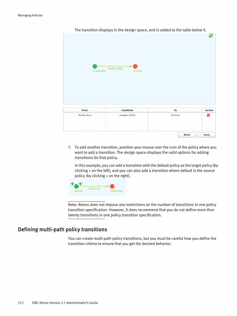
Managing Policies
The transition displays in the design space, and is added to the table below it.
7. To add another transition, position your mouse over the icon of the policy where you want to add a transition. The design space displays the valid options for adding transitions for that policy.
In this example, you can add a transition with the default policy as the target policy (by clicking + on the left), and you can also add a transition where default is the source policy (by clicking + on the right).
Note: Atmos does not impose any restrictions on the number of transitions in one policy transition specification. However, it does recommend that you do not define more than twenty transitions in one policy transition specification.
Defining multi-path policy transitions
You can create multi-path policy transitions, but you must be careful how you define the transition criteria to ensure that you get the desired behavior.
212 EMC Atmos Version 2.1 Administrator’s Guide

Managing Policies
For example, if you define the transition for both access and modify using the same time interval, as shown in Figure 31, the modify path will never be followed because the access time transition will be followed on both an object access and an object modify. This occurs because an object modify operation also always changes the access time.
Figure 31 Multi-path policy transitions
Policy transitions and Retention/Deletion
You can use the retention and deletion option, but they can only be used in the final policy specification of a policy transition specification.
If you use either a retention or a deletion policy, remember that retention and deletion are measured in relation to the object’s create time, and not in relation to the time when the object moves to the policy specification where the retention or deletion is defined. For example, suppose you have a policy specification like this:
◆ Enter Policy1 when the object is created.
◆ Transition to Policy2, one year after entering Policy1. Policy2 specifies a deletion period of two years.
Figure 32 Policy transition with deletion enabled example
Working with policy transition specifications 213

Managing Policies
You might expect that the object would be deleted 2 years after the object entered Policy2 (or three years after the object was created). However, because deletion is based on the object’s create time, it would be deleted 1 year after entering Policy2 (or two years after the object was created).
Removing a single transition
To delete a single transition:
◆ Select the transition, then click the delete icon in the design space, for example:
OR
◆ Select the transition in the table, then click the delete icon. For example:
Note: You cannot modify the definition of a transition in this release. To change the transition definition, delete and recreate it.
Policy transition icons
The designer uses these icons to indicate the state of the transition:
Table 36 Policy transition icons
Icon What it means
Identifies the first policy in the workflow (green).
Identifies the last policy in the workflow. (red)
Identifies a policy transition that is in the middle of the workflow. (blue)
Adds a transition to the specification. You access it by placing your mouse over a policy icon in the design area.
Deletes the transition.
Refreshes the design area.
214 EMC Atmos Version 2.1 Administrator’s Guide
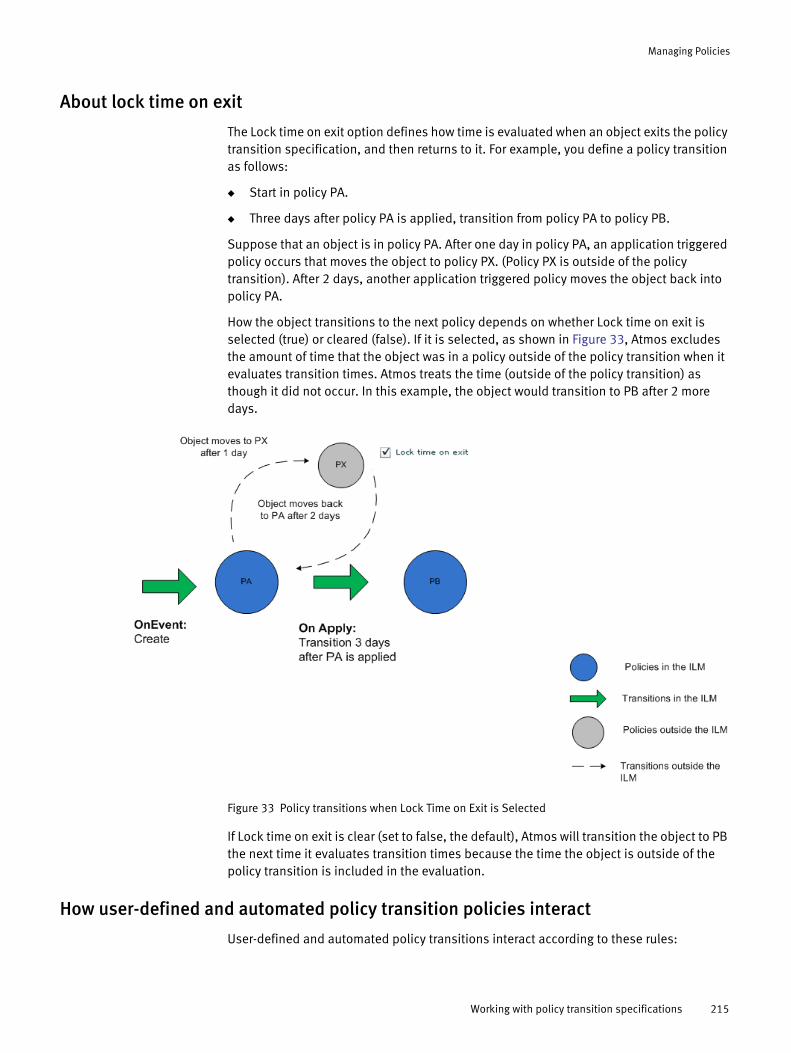
Managing Policies
About lock time on exit
The Lock time on exit option defines how time is evaluated when an object exits the policy transition specification, and then returns to it. For example, you define a policy transition as follows:
◆ Start in policy PA.
◆ Three days after policy PA is applied, transition from policy PA to policy PB.
Suppose that an object is in policy PA. After one day in policy PA, an application triggered policy occurs that moves the object to policy PX. (Policy PX is outside of the policy transition). After 2 days, another application triggered policy moves the object back into policy PA.
How the object transitions to the next policy depends on whether Lock time on exit is selected (true) or cleared (false). If it is selected, as shown in Figure 33, Atmos excludes the amount of time that the object was in a policy outside of the policy transition when it evaluates transition times. Atmos treats the time (outside of the policy transition) as though it did not occur. In this example, the object would transition to PB after 2 more days.
Figure 33 Policy transitions when Lock Time on Exit is Selected
If Lock time on exit is clear (set to false, the default), Atmos will transition the object to PB the next time it evaluates transition times because the time the object is outside of the policy transition is included in the evaluation.
How user-defined and automated policy transition policies interact
User-defined and automated policy transitions interact according to these rules:
Working with policy transition specifications 215
Managing Policies
◆ If a policy transition specification is assigned to an object, Atmos manages the object as defined by the policy transition specification.
◆ If a policy transition specification is assigned to an object, and the object’s policy is changed manually, the change will overwrite the current policy specified by the policy transition specification. However, the policy transitions will remain active, and the next transition will bring the object back into the set of states described by the policy transition specification. You can stop the transitions by suspending the policy transition specification.
◆ If you remove the policy transition specification from an object, the object remains with the current policy. The current policy is not changed unless a new policy transition specification is attached to the object, or the policy is changed manually by an application-driven Atmos policy change.
◆ The policy transition specification includes a set of individual policies. After a policy transition is assigned to an object, the attributes of the underlying policy specifications (such as, number and type of replicas) can be changed. When a transition to a changed policy occurs, the attributes of the policy at the moment of the transition are used, not the original attributes.
◆ If the target policy specified in a transition has been deleted from the system, an object will remain in its current state until a transition to an existing policy is triggered or a manual policy change occurs.
Policy transition limitations
◆ Policy transitions can only proceed to target policies that are ahead of the current policy in the transition definition.
For example, suppose the transition definition specifies that the transitions are policy1 to policy2 to policy3. If the current policy is policy2, you can explicitly change the policy to policy3 by using a different policy selector, but not to policy1.
◆ You cannot find all objects associated with one specified policy transition specification, or find objects in a specific transition state.
◆ Policy transition content changes are not tracked.
If a transition specification is changed, objects created after the change will use the new transition specification. Objects already managed by it will also start to transition according to the new specification (beginning with the next transition). Existing objects cannot continue to use an old transition definition.
◆ Policy transitions do not require at least one common synchronous replica between the source and target policies. In rare circumstances, a very small number of objects might not make the full transition to the target policy.
◆ Policy transitions are evaluated once per day (at midnight).
For example, suppose you defined a policy transition specification that included four transitions. Each transition was triggered 3 hours after the last policy was applied. Because Atmos evaluates all transitions one time per day, any objects that used this policy transition specification would move through all four transitions during that policy evaluation window.
216 EMC Atmos Version 2.1 Administrator’s Guide

Managing Policies
Policy exampleThis section shows how to create:
◆ Three policy specifications.
◆ One policy selector, and assign it to a tenant.
◆ One policy transition specification to automate transitions from one policy specification to another on age-based conditions.
This example shows how to create the Atmos policies that meet this use case:
◆ When an object is first created, apply the Production policy.
• The Production policy has 2 sync replicas and 2 async replicas.
◆ If the object has been in the Production policy for 6 months, apply the Archive policy.
• The Archive policy has 1 sync replica and 1 async replica.
◆ If the object has not been accessed in 3 months, apply the FinalArchive policy.
• The FinalArchive policy has 1 sync Geoparity replica.
Figure 34, “Atmos policy example,” illustrates the object lifecyle.
Figure 34 Atmos policy example
To define this lifecycle, you complete through the following procedures:
◆ “Creating the Production policy”
◆ “Creating the Archive Policy”
◆ “Creating the FinalArchive Policy”
◆ “Automating the object lifecycle by using a policy transition specification”
Creating the Production policy
1. Login to the Tenant dashboard (using TenantAdmin credentials).
2. From the Tenant Dashboard, click Add to open the policy specifications page.
3. In the Policy Specification Name field, type Production.
4. Because this policy specification requires 4 replicas, click Add Replicas three times. (One replica is already defined by default.) For Replica 3 and Replica 4, change the Replica type to Async.
5. Click Save.
Policy example 217
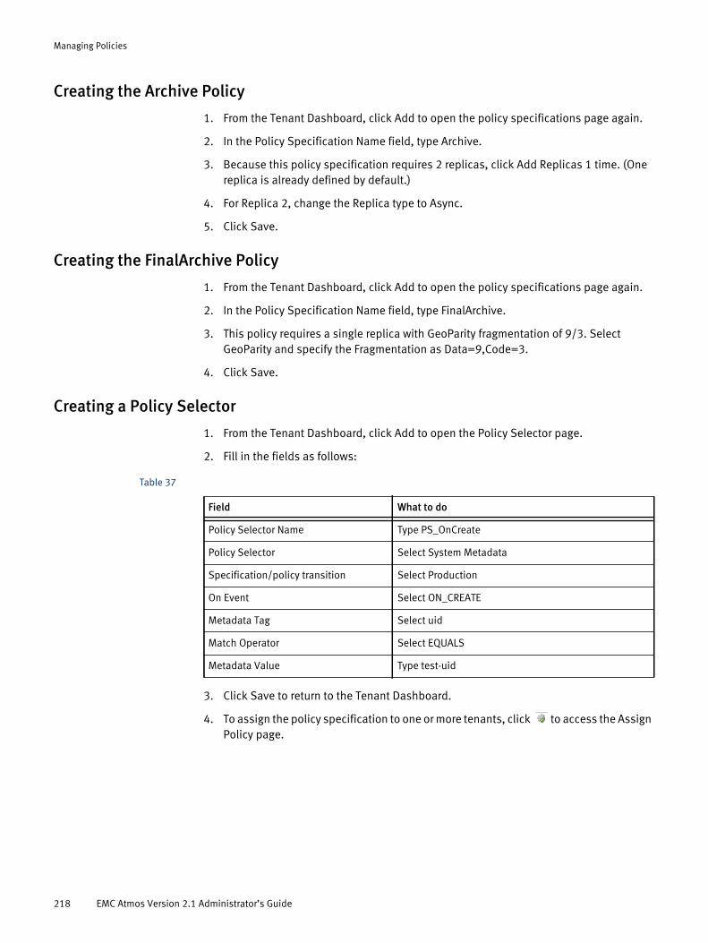
Managing Policies
Creating the Archive Policy
1. From the Tenant Dashboard, click Add to open the policy specifications page again.
2. In the Policy Specification Name field, type Archive.
3. Because this policy specification requires 2 replicas, click Add Replicas 1 time. (One replica is already defined by default.)
4. For Replica 2, change the Replica type to Async.
5. Click Save.
Creating the FinalArchive Policy
1. From the Tenant Dashboard, click Add to open the policy specifications page again.
2. In the Policy Specification Name field, type FinalArchive.
3. This policy requires a single replica with GeoParity fragmentation of 9/3. Select GeoParity and specify the Fragmentation as Data=9,Code=3.
4. Click Save.
Creating a Policy Selector
1. From the Tenant Dashboard, click Add to open the Policy Selector page.
2. Fill in the fields as follows:
3. Click Save to return to the Tenant Dashboard.
4. To assign the policy specification to one or more tenants, click to access the Assign Policy page.
Table 37
Field What to do
Policy Selector Name Type PS_OnCreate
Policy Selector Select System Metadata
Specification/policy transition Select Production
On Event Select ON_CREATE
Metadata Tag Select uid
Match Operator Select EQUALS
Metadata Value Type test-uid
218 EMC Atmos Version 2.1 Administrator’s Guide
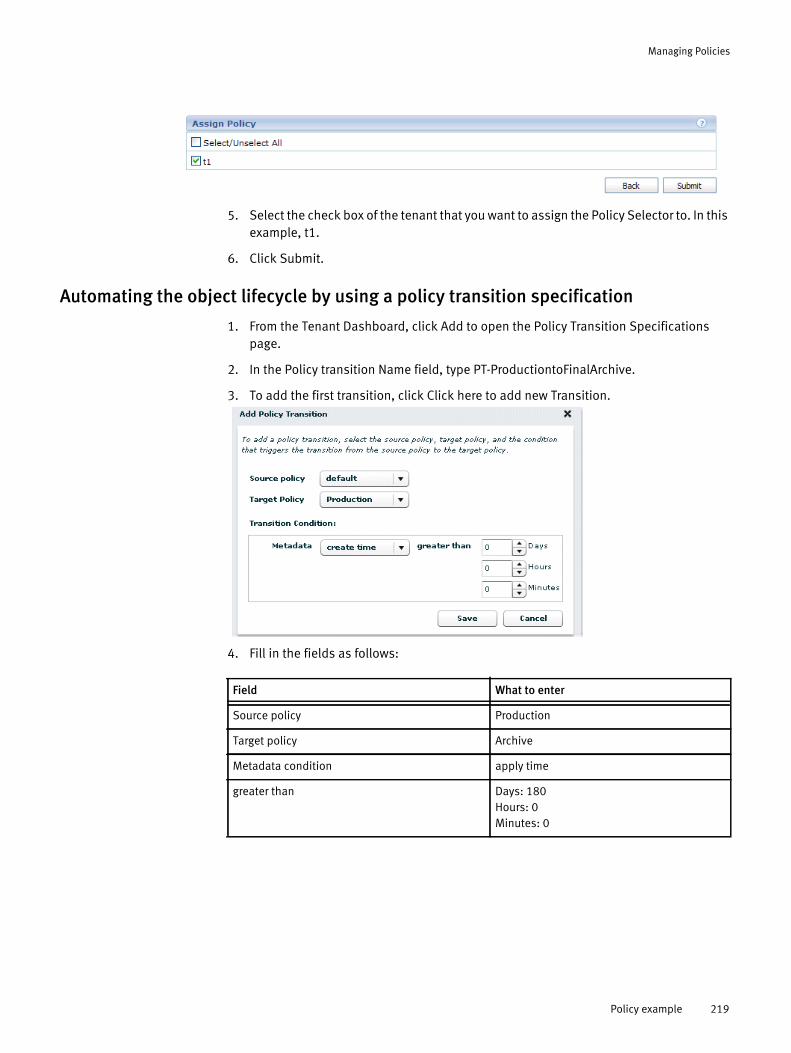
Managing Policies
5. Select the check box of the tenant that you want to assign the Policy Selector to. In this example, t1.
6. Click Submit.
Automating the object lifecycle by using a policy transition specification
1. From the Tenant Dashboard, click Add to open the Policy Transition Specifications page.
2. In the Policy transition Name field, type PT-ProductiontoFinalArchive.
3. To add the first transition, click Click here to add new Transition.
4. Fill in the fields as follows:
Field What to enter
Source policy Production
Target policy Archive
Metadata condition apply time
greater than Days: 180Hours: 0Minutes: 0
Policy example 219
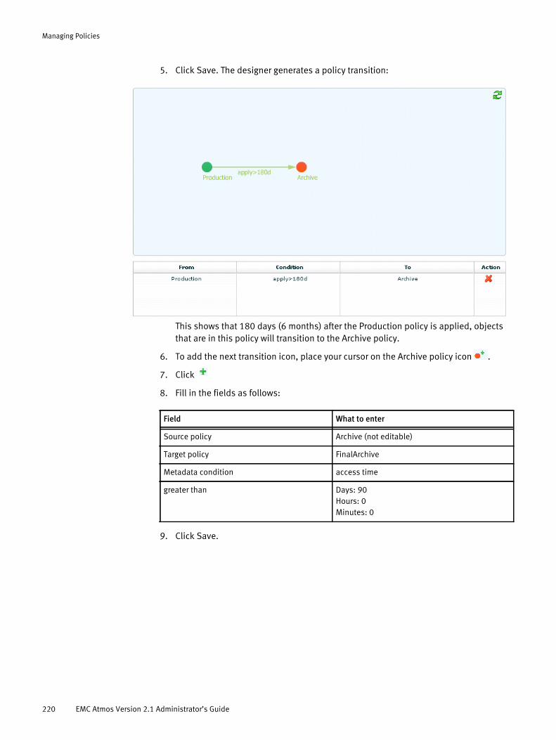
Managing Policies
5. Click Save. The designer generates a policy transition:
This shows that 180 days (6 months) after the Production policy is applied, objects that are in this policy will transition to the Archive policy.
6. To add the next transition icon, place your cursor on the Archive policy icon .
7. Click
8. Fill in the fields as follows:
9. Click Save.
Field What to enter
Source policy Archive (not editable)
Target policy FinalArchive
Metadata condition access time
greater than Days: 90Hours: 0Minutes: 0
220 EMC Atmos Version 2.1 Administrator’s Guide

Managing Policies
10. The specification is now complete. Click Save to return to the Tenant dashboard.
Policy example 221

Managing Policies
222 EMC Atmos Version 2.1 Administrator’s Guide

PART 3
SubtenantAdmin
Includes the following chapter:
Chapter 11, “SubtenantAdmin Basics.”
Describes the SubtenantAdmin responsibilities and tools to manage UIDs and shared secrets, to configure access nodes for NFS and CIFS, and to reorder policy selectors.

CHAPTER 11SubtenantAdmin Basics
Describes the SubtenantAdmin responsibilities and tools. It includes the following topics:
◆ Overview............................................................................................................... 226◆ Working with UIDs and shared secrets .................................................................. 228◆ Configuring access nodes for NFS ......................................................................... 229◆ Configuring Access Nodes for CIFS ........................................................................ 232◆ Reordering policy selectors ................................................................................... 234
SubtenantAdmin Basics 225
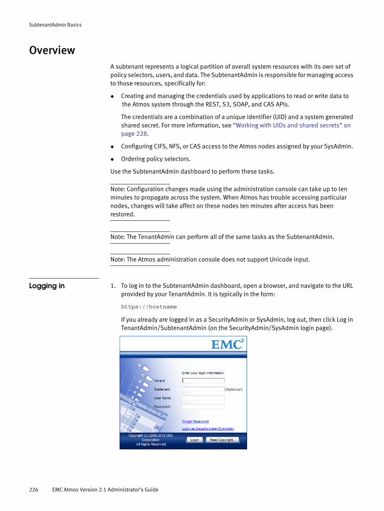
SubtenantAdmin Basics
OverviewA subtenant represents a logical partition of overall system resources with its own set of policy selectors, users, and data. The SubtenantAdmin is responsible for managing access to those resources, specifically for:
◆ Creating and managing the credentials used by applications to read or write data to the Atmos system through the REST, S3, SOAP, and CAS APIs.
The credentials are a combination of a unique identifier (UID) and a system generated shared secret. For more information, see “Working with UIDs and shared secrets” on page 228.
◆ Configuring CIFS, NFS, or CAS access to the Atmos nodes assigned by your SysAdmin.
◆ Ordering policy selectors.
Use the SubtenantAdmin dashboard to perform these tasks.
Note: Configuration changes made using the administration console can take up to ten minutes to propagate across the system. When Atmos has trouble accessing particular nodes, changes will take affect on these nodes ten minutes after access has been restored.
Note: The TenantAdmin can perform all of the same tasks as the SubtenantAdmin.
Note: The Atmos administration console does not support Unicode input.
Logging in 1. To log in to the SubtenantAdmin dashboard, open a browser, and navigate to the URL provided by your TenantAdmin. It is typically in the form:
https://hostname
If you already are logged in as a SecurityAdmin or SysAdmin, log out, then click Log in TenantAdmin/SubtenantAdmin (on the SecurityAdmin/SysAdmin login page).
226 EMC Atmos Version 2.1 Administrator’s Guide

SubtenantAdmin Basics
2. Enter the login credentials you received from your TenantAdmin:
• Tenant — Enter the tenant name.
• Subtenant — Enter the subtenant name.
• User Name/Password — Enter the SubtenantAdmin credentials.
3. Click Login.
If you forget your password, click Forgot Password and your password is emailed to you if an email address and an SMTP server were setup when your SubtenantAdmin credentials were established. Contact your TenantAdmin for more information.
Using the SubTenant DashboardWhen you successfully log in, the Subtenant Dashboard displays:
The following table describes the Subtenant Dashboard fields.
Table 38
Field Description
Subtenant ID Displays the subtenant’s unique identifier. This ID is auto-generated by the Atmos system. This ID, the UID and a shared secret are used on web services authentication requests.
Subtenant Name Displays the name the TenantAdmin has assigned to this subtenant.
Tenant Name Displays the name of the tenant the subtenant belongs to.
Authentication Source Specifies the authentication source defined for the subtenant by the TenantAdmin.
Using the SubTenant Dashboard 227

SubtenantAdmin Basics
Working with UIDs and shared secretsA UID is a unique identifier that represents a user or application that wants to read or write data to the Atmos system using the REST or SOAP API. To perform operations on Atmos CAS using the Atmos CAS API, applications must use a combination of UID and subtenant ID in the connection string. TenantAdmins and SubtenantAdmins are responsible for managing them.
When you create a UID, Atmos generates a unique key (or shared secret) for it. For Atmos CAS, applications may use a PEA (Pool Entry Authorization) file to store the credentials for the UID and subtenant ID combination. Once these credentials are created, you can provide them to the application developer who will use the combination to authenticate their application on web service requests.
To create a UID:
Note: If you are running Atmos LE, you are allowed to create a maximum of 50 UIDs.
1. Go to the UID List area, then click Add. The Add UID page appears.
2. In the UID field type a new UID that is unique within the subtenant. It is a string that can:
Used Capacity Displays the total disk space used by the subtenant.
Default Policy Specification Displays the default policy specification name assigned to the subtenant by this TenantAdmin. The default policy is the policy that is applied to objects entering the Atmos system when an object does not meet the requirements for any other policy. Contact the TenantAdmin for details on this policy.
UID List Displays information about the web services UIDS and shared secrets that are defined for the subtenant. For more information about UIDs, see “Working with UIDs and shared secrets”.
Access Nodes For NIFS/CFS Displays information about the nodes available to the subtenant. For more information about configuring CIFS/NFS/CAS for these nodes, see “Configuring access nodes for NFS” on page 229, “Configuring Access Nodes for CIFS” on page 232, and “Removing access node assignments” on page 106.
Policy Selectors Displays the policy selectors that are available for the subtenant. The TenantAdmin enables access to these policy selectors. Contact your TenantAdmin for more information.
Table 38
Field Description
228 EMC Atmos Version 2.1 Administrator’s Guide

SubtenantAdmin Basics
• Be a maximum of 255 characters.
• Contain the letters a to z (both upper and lower case) and digits 0 to 9.
• The set of valid special characters depends on the authentication source:
– A UID stored in an LDAP source can support these special characters: at sign(@), period (.), and underscore (_).
If unsupported characters are used, Atmos cannot retrieve the corresponding shared secret for the UID. This limitation does not apply to UIDs stored in the local lockbox.
– A UID stored in the local lockbox can include the following special characters: - _ @ $ ^ , ; | [ ] ( ) and { }
Note: If the UID will be used with Atmos Cloud Delivery Platform (ACDP), do not use the pipe symbol (|) or you will be unable to gather usage information for that UID as ACDP interprets this character as a delimiter.
3. Optionally, enter an email address. This is used to email the secret key, if that action is specified on the Subtenant Dashboard.
4. Click Add. The Subtenant Information page appears, listing the new UID and the Shared Secret that the system generated for it.
Note: There is a slight delay before the UID is available on all Atmos nodes.
5. Give this information to your application developer for use in authenticating access to the system for Web-service requests.
Disabling, enabling, and regenerating the shared secretYou can disable, enable, or regenerate the shared secret. Remember that:
◆ When you disable a shared secret, the application is no longer able to access the system through web services.
◆ To restore access, enable the shared secret.
◆ When you regenerate a shared secret, the application has to use the new shared secret to access the system.
◆ You cannot revert to a previous shared secret after the regenerate shared secret operation has been performed.
Configuring access nodes for NFS
Note: Before you configure NFS or CIFS access to Atmos, synchronize your external servers’ times with your Atmos NTP server time (see “Configuring the system master serial number” on page 74.
To configure NFS:
1. Navigate to the Access Nodes for NFS/CIFS area which shows the list of nodes with the NFS or CIFS service which can be accessed.
Configuring access nodes for NFS 229

SubtenantAdmin Basics
2. Under Service Type, click the appropriate NFS link. The Node NFS Information page appears.
3. To get details about a share, move your mouse anywhere over the table row for that share, and a popup window appears.
• To add a new NFS share, click Add.
• To edit an existing NFS share, click Edit.
• To remove the share, click Remove. This operations removes the specified NFS share path from the access node, but it does not remove any data from the share.
If you click Add or Edit, the NFS Configuration page appears.
230 EMC Atmos Version 2.1 Administrator’s Guide

SubtenantAdmin Basics
4. Add or edit the fields on the NFS Configuration page. Parameters with red asterisks are required.
Field Description
Share Path Specify the relative path of the directory under /mnt/mauifs/. It cannot include these characters: & < > ' or ". This field cannot be greater than 256 characters.
Note: This field does not support Unicode characters.
The resulting mount path depends on whether your SysAdmin has enabled Multi-Subtenant FS Access. For example, if you specify Share Path as nfsdir, and Multi-Subtenant FS Acccess is disabled, the resulting mount path is: /mnt/mauifs/nfsdir
If Multi-Subtenant FS Access is enabled, the resulting NFS mount path is:/mnt/mauifs/<subtenantuuid>/nfsdir
When editing an existing share, this field is populated and cannot be changed.
Allow Host The hosts that access the share. Valid values are:Single machine—A fully qualified domain name (which can be resolved by the server), hostname (which can be resolved by the server), or IP address.Series of machines specified with wildcards—Use the * or ? character to specify a string match. Wildcards are not to be used with IP addresses; however, they may work accidentally if reverse DNS lookups fail. When specifying wildcards in fully qualified domain names, dots (.) are not included in the wildcard. For example, *.example.com includes one.example.com but does not include one.two.example.com.IP networks—Use a.b.c.d/z, where a.b.c.d is the network and z is the number of bits in the netmask (for example, 192.168.0.0/24). Another acceptable format is a.b.c.d/netmask, where a.b.c.d is the network and netmask is the netmask (for example, 192.168.100.8/255.255.255.0).Netgroups—Use the format @group-name, where group-name is the NIS netgroup name.
Permission Specifies whether the directory is read-only or has read/write permissions The default is Read/Write.
Configuring access nodes for NFS 231
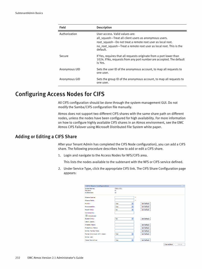
SubtenantAdmin Basics
Configuring Access Nodes for CIFSAll CIFS configuration should be done through the system-management GUI. Do not modify the Samba/CIFS configuration file manually.
Atmos does not support two different CIFS shares with the same share path on different nodes, unless the nodes have been configured for high availability. For more information on how to configure highly available CIFS shares in an Atmos environment, see the EMC Atmos CIFS Failover using Microsoft Distributed File System white paper.
Adding or Editing a CIFS Share
After your Tenant Admin has completed the CIFS Node configuration), you can add a CIFS share. The following procedure describes how to add or edit a CIFS share.
1. Login and navigate to the Access Nodes for NFS/CIFS area.
This lists the nodes available to the subtenant with the NFS or CIFS service defined.
2. Under Service Type, click the appropriate CIFS link. The CIFS Share Configuration page appears:
Authorization User access. Valid values are:all_squash—Treat all client users as anonymous users.root_squash—Do not treat a remote root user as local root.no_root_squash—Treat a remote root user as local root. This is the default.
Secure If Yes, requires that all requests originate from a port lower than 1024. If No, requests from any port number are accepted. The default is Yes.
Anonymous UID Sets the user ID of the anonymous account, to map all requests to one user.
Anonymous GID Sets the group ID of the anonymous account, to map all requests to one user.
Field Description
232 EMC Atmos Version 2.1 Administrator’s Guide
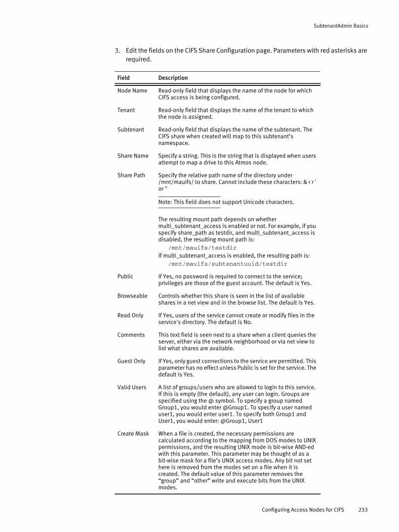
SubtenantAdmin Basics
3. Edit the fields on the CIFS Share Configuration page. Parameters with red asterisks are required.
Field Description
Node Name Read-only field that displays the name of the node for which CIFS access is being configured.
Tenant Read-only field that displays the name of the tenant to which the node is assigned.
Subtenant Read-only field that displays the name of the subtenant. The CIFS share when created will map to this subtenant’s namespace.
Share Name Specify a string. This is the string that is displayed when users attempt to map a drive to this Atmos node.
Share Path Specify the relative path name of the directory under /mnt/mauifs/ to share. Cannot include these characters: & < > ' or "
Note: This field does not support Unicode characters.
The resulting mount path depends on whether multi_subtenant_access is enabled or not. For example, if you specify share_path as testdir, and multi_subtenant_access is disabled, the resulting mount path is:
/mnt/mauifs/testdir
If multi_subtenant_access is enabled, the resulting path is:/mnt/mauifs/subtenantuuid/testdir
Public If Yes, no password is required to connect to the service; privileges are those of the guest account. The default is Yes.
Browseable Controls whether this share is seen in the list of available shares in a net view and in the browse list. The default is Yes.
Read Only If Yes, users of the service cannot create or modify files in the service's directory. The default is No.
Comments This text field is seen next to a share when a client queries the server, either via the network neighborhood or via net view to list what shares are available.
Guest Only If Yes, only guest connections to the service are permitted. This parameter has no effect unless Public is set for the service. The default is Yes.
Valid Users A list of groups/users who are allowed to login to this service. If this is empty (the default), any user can login. Groups are specified using the @ symbol. To specify a group named Group1, you would enter @Group1. To specify a user named user1, you would enter user1. To specify both Group1 and User1, you would enter: @Group1, User1
Create Mask When a file is created, the necessary permissions are calculated according to the mapping from DOS modes to UNIX permissions, and the resulting UNIX mode is bit-wise AND-ed with this parameter. This parameter may be thought of as a bit-wise mask for a file’s UNIX access modes. Any bit not set here is removed from the modes set on a file when it is created. The default value of this parameter removes the “group” and “other” write and execute bits from the UNIX modes.
Configuring Access Nodes for CIFS 233
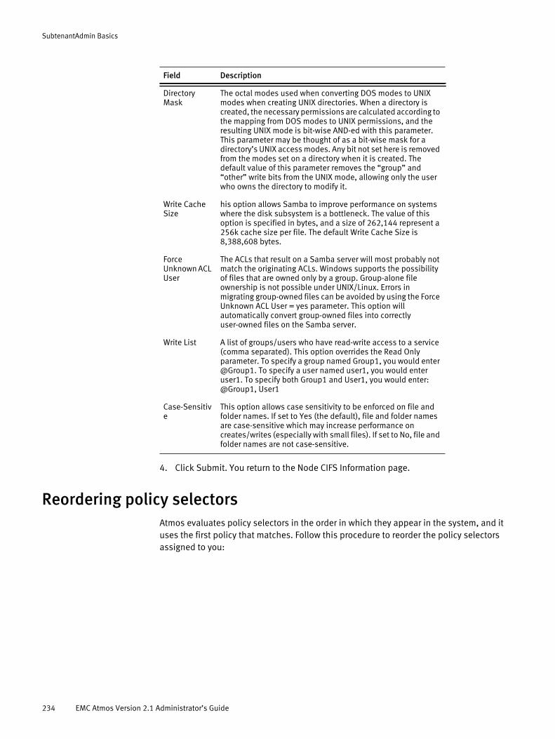
SubtenantAdmin Basics
4. Click Submit. You return to the Node CIFS Information page.
Reordering policy selectorsAtmos evaluates policy selectors in the order in which they appear in the system, and it uses the first policy that matches. Follow this procedure to reorder the policy selectors assigned to you:
Directory Mask
The octal modes used when converting DOS modes to UNIX modes when creating UNIX directories. When a directory is created, the necessary permissions are calculated according to the mapping from DOS modes to UNIX permissions, and the resulting UNIX mode is bit-wise AND-ed with this parameter. This parameter may be thought of as a bit-wise mask for a directory’s UNIX access modes. Any bit not set here is removed from the modes set on a directory when it is created. The default value of this parameter removes the “group” and “other” write bits from the UNIX mode, allowing only the user who owns the directory to modify it.
Write Cache Size
his option allows Samba to improve performance on systems where the disk subsystem is a bottleneck. The value of this option is specified in bytes, and a size of 262,144 represent a 256k cache size per file. The default Write Cache Size is 8,388,608 bytes.
Force Unknown ACL User
The ACLs that result on a Samba server will most probably not match the originating ACLs. Windows supports the possibility of files that are owned only by a group. Group-alone file ownership is not possible under UNIX/Linux. Errors in migrating group-owned files can be avoided by using the Force Unknown ACL User = yes parameter. This option will automatically convert group-owned files into correctly user-owned files on the Samba server.
Write List A list of groups/users who have read-write access to a service (comma separated). This option overrides the Read Only parameter. To specify a group named Group1, you would enter @Group1. To specify a user named user1, you would enter user1. To specify both Group1 and User1, you would enter: @Group1, User1
Case-Sensitive
This option allows case sensitivity to be enforced on file and folder names. If set to Yes (the default), file and folder names are case-sensitive which may increase performance on creates/writes (especially with small files). If set to No, file and folder names are not case-sensitive.
Field Description
234 EMC Atmos Version 2.1 Administrator’s Guide

SubtenantAdmin Basics
1. In the Policy Selectors area, click Reorder. The Reorder Policy page appears.
2. Use the Up and Down buttons to reorder the policies.
3. Click Submit.
Reordering policy selectors 235

SubtenantAdmin Basics
236 EMC Atmos Version 2.1 Administrator’s Guide

PART 4
Appendices
This part includes the following appendices:
Appendix A, “Atmos Event Reference”
This appendix provides descriptions and other information about Atmos events.
Appendix B, “Atmos MIB”
This appendix provides descriptions and other information specific to the Atmos MIB.
Appendix C, “MIB-II (RFC 1213)”
This appendix provides descriptions and other information specific to MIB-II.
Appendix D, “Host Resources MIB (RFC 2790)”
This appendix provides descriptions and other information specific to the Host Resources MIB.

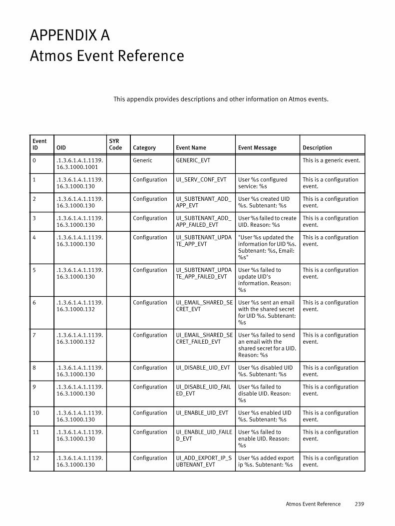
APPENDIX AAtmos Event Reference
This appendix provides descriptions and other information on Atmos events.
Event ID OID
SYR Code Category Event Name Event Message Description
0 .1.3.6.1.4.1.1139.16.3.1000.1001
Generic GENERIC_EVT This is a generic event.
1 .1.3.6.1.4.1.1139.16.3.1000.130
Configuration UI_SERV_CONF_EVT User %s configured service: %s
This is a configuration event.
2 .1.3.6.1.4.1.1139.16.3.1000.130
Configuration UI_SUBTENANT_ADD_APP_EVT
User %s created UID %s. Subtenant: %s
This is a configuration event.
3 .1.3.6.1.4.1.1139.16.3.1000.130
Configuration UI_SUBTENANT_ADD_APP_FAILED_EVT
User %s failed to create UID. Reason: %s
This is a configuration event.
4 .1.3.6.1.4.1.1139.16.3.1000.130
Configuration UI_SUBTENANT_UPDATE_APP_EVT
"User %s updated the information for UID %s. Subtenant: %s, Email: %s"
This is a configuration event.
5 .1.3.6.1.4.1.1139.16.3.1000.130
Configuration UI_SUBTENANT_UPDATE_APP_FAILED_EVT
User %s failed to update UID's information. Reason: %s
This is a configuration event.
6 .1.3.6.1.4.1.1139.16.3.1000.132
Configuration UI_EMAIL_SHARED_SECRET_EVT
User %s sent an email with the shared secret for UID %s. Subtenant: %s
This is a configuration event.
7 .1.3.6.1.4.1.1139.16.3.1000.132
Configuration UI_EMAIL_SHARED_SECRET_FAILED_EVT
User %s failed to send an email with the shared secret for a UID. Reason: %s
This is a configuration event.
8 .1.3.6.1.4.1.1139.16.3.1000.130
Configuration UI_DISABLE_UID_EVT User %s disabled UID %s. Subtenant: %s
This is a configuration event.
9 .1.3.6.1.4.1.1139.16.3.1000.130
Configuration UI_DISABLE_UID_FAILED_EVT
User %s failed to disable UID. Reason: %s
This is a configuration event.
10 .1.3.6.1.4.1.1139.16.3.1000.130
Configuration UI_ENABLE_UID_EVT User %s enabled UID %s. Subtenant: %s
This is a configuration event.
11 .1.3.6.1.4.1.1139.16.3.1000.130
Configuration UI_ENABLE_UID_FAILED_EVT
User %s failed to enable UID. Reason: %s
This is a configuration event.
12 .1.3.6.1.4.1.1139.16.3.1000.130
Configuration UI_ADD_EXPORT_IP_SUBTENANT_EVT
User %s added export ip %s. Subtenant: %s
This is a configuration event.
Atmos Event Reference 239

Atmos Event Reference
13 .1.3.6.1.4.1.1139.16.3.1000.130
Configuration UI_ADD_EXPORT_IP_SUBTENANT_FAILED_EVT
User %s failed to add export ip to subtenant. Reason: %s
This is a configuration event.
14 .1.3.6.1.4.1.1139.16.3.1000.130
Configuration UI_DELETE_EXPORT_IP_EVT
User %s deleted export ip %s. Subtenant: %s
This is a configuration event.
15 .1.3.6.1.4.1.1139.16.3.1000.130
Configuration UI_DELETE_EXPORT_IP_FAILED_EVT
User %s failed to delete export ip from subtenant. Reason: %s
This is a configuration event.
16 .1.3.6.1.4.1.1139.16.3.1000.131
Configuration UI_REMOVE_SYSADMIN_EVT
User %s removed the System Administrator role from user %s.
This is a configuration event.
17 .1.3.6.1.4.1.1139.16.3.1000.131
Configuration UI_REMOVE_SYSADMIN_FAILED_EVT
User %s failed to remove the System Administrator role from specified account. Reason: %s
This is a configuration event.
18 .1.3.6.1.4.1.1139.16.3.1000.131
Configuration UI_ADD_SYSADMIN_EVT
User %s assigned the System Administrator role to user %s.
This is a configuration event.
19 .1.3.6.1.4.1.1139.16.3.1000.131
Configuration UI_ADD_SYSADMIN_FAILED_EVT
User %s failed to assign the System Administrator role to the specified account. Reason: %s
This is a configuration event.
20 .1.3.6.1.4.1.1139.16.3.1000.130
Configuration UI_CHG_USER_INFO_EVT
User %s updated their account information. Auth_source: %s Email: %s Phone: %s Mobile: %s
This is a configuration event.
21 .1.3.6.1.4.1.1139.16.3.1000.130
Configuration UI_CHG_USER_INFO_FAILED_EVT
User %s failed to update their account information. Reason: %s
This is a configuration event.
22 .1.3.6.1.4.1.1139.16.3.1000.130
Configuration UI_DEL_PLACE_POLICY_VECTOR_EVT
User %s deleted placement policy vector %s from tenant %s.
This is a configuration event.
23 .1.3.6.1.4.1.1139.16.3.1000.130
Configuration UI_DEL_PLACE_POLICY_VECTOR_FAILED_EVT
User %s failed to delete placement policy vector from tenant. Reason: %s
This is a configuration event.
24 .1.3.6.1.4.1.1139.16.3.1000.130
Configuration UI_CREATE_PLACE_POLICY_EVT
User %s created placement policy selector %s for tenant %s.
This is a configuration event.
25 .1.3.6.1.4.1.1139.16.3.1000.130
Configuration UI_CREATE_PLACE_POLICY_FAILED_EVT
User %s failed to create placement policy selector for specified tenant. Reason: %s
This is a configuration event.
Event ID OID
SYR Code Category Event Name Event Message Description
240 EMC Atmos Version 2.1 Administrator’s Guide
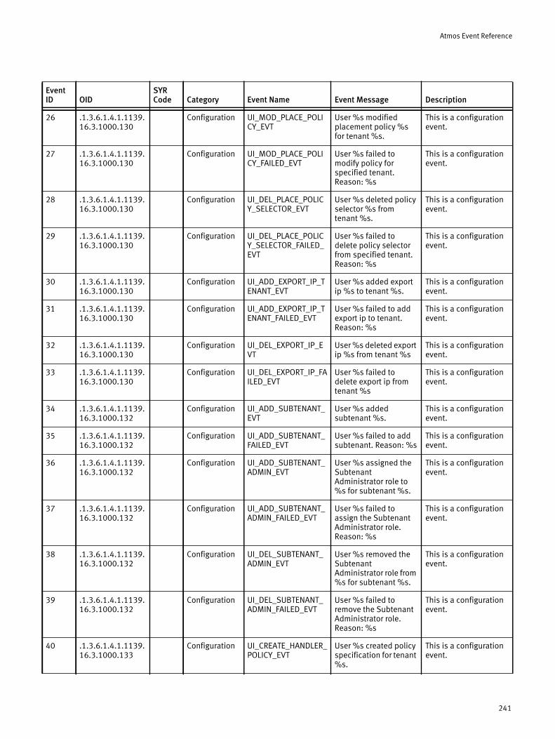
Atmos Event Reference
26 .1.3.6.1.4.1.1139.16.3.1000.130
Configuration UI_MOD_PLACE_POLICY_EVT
User %s modified placement policy %s for tenant %s.
This is a configuration event.
27 .1.3.6.1.4.1.1139.16.3.1000.130
Configuration UI_MOD_PLACE_POLICY_FAILED_EVT
User %s failed to modify policy for specified tenant. Reason: %s
This is a configuration event.
28 .1.3.6.1.4.1.1139.16.3.1000.130
Configuration UI_DEL_PLACE_POLICY_SELECTOR_EVT
User %s deleted policy selector %s from tenant %s.
This is a configuration event.
29 .1.3.6.1.4.1.1139.16.3.1000.130
Configuration UI_DEL_PLACE_POLICY_SELECTOR_FAILED_EVT
User %s failed to delete policy selector from specified tenant. Reason: %s
This is a configuration event.
30 .1.3.6.1.4.1.1139.16.3.1000.130
Configuration UI_ADD_EXPORT_IP_TENANT_EVT
User %s added export ip %s to tenant %s.
This is a configuration event.
31 .1.3.6.1.4.1.1139.16.3.1000.130
Configuration UI_ADD_EXPORT_IP_TENANT_FAILED_EVT
User %s failed to add export ip to tenant. Reason: %s
This is a configuration event.
32 .1.3.6.1.4.1.1139.16.3.1000.130
Configuration UI_DEL_EXPORT_IP_EVT
User %s deleted export ip %s from tenant %s
This is a configuration event.
33 .1.3.6.1.4.1.1139.16.3.1000.130
Configuration UI_DEL_EXPORT_IP_FAILED_EVT
User %s failed to delete export ip from tenant %s
This is a configuration event.
34 .1.3.6.1.4.1.1139.16.3.1000.132
Configuration UI_ADD_SUBTENANT_EVT
User %s added subtenant %s.
This is a configuration event.
35 .1.3.6.1.4.1.1139.16.3.1000.132
Configuration UI_ADD_SUBTENANT_FAILED_EVT
User %s failed to add subtenant. Reason: %s
This is a configuration event.
36 .1.3.6.1.4.1.1139.16.3.1000.132
Configuration UI_ADD_SUBTENANT_ADMIN_EVT
User %s assigned the Subtenant Administrator role to %s for subtenant %s.
This is a configuration event.
37 .1.3.6.1.4.1.1139.16.3.1000.132
Configuration UI_ADD_SUBTENANT_ADMIN_FAILED_EVT
User %s failed to assign the Subtenant Administrator role. Reason: %s
This is a configuration event.
38 .1.3.6.1.4.1.1139.16.3.1000.132
Configuration UI_DEL_SUBTENANT_ADMIN_EVT
User %s removed the Subtenant Administrator role from %s for subtenant %s.
This is a configuration event.
39 .1.3.6.1.4.1.1139.16.3.1000.132
Configuration UI_DEL_SUBTENANT_ADMIN_FAILED_EVT
User %s failed to remove the Subtenant Administrator role. Reason: %s
This is a configuration event.
40 .1.3.6.1.4.1.1139.16.3.1000.133
Configuration UI_CREATE_HANDLER_POLICY_EVT
User %s created policy specification for tenant %s.
This is a configuration event.
Event ID OID
SYR Code Category Event Name Event Message Description
241
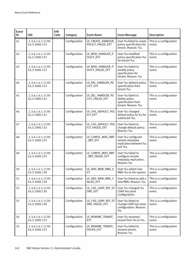
Atmos Event Reference
41 .1.3.6.1.4.1.1139.16.3.1000.133
Configuration UI_CREATE_HANDLER_POLICY_FAILED_EVT
User %s failed to create policy specification for tenant. Reason: %s
This is a configuration event.
42 .1.3.6.1.4.1.1139.16.3.1000.133
Configuration UI_MOD_HANDLER_POLICY_EVT
User %s modified policy specification %s for tenant %s.
This is a configuration event.
43 .1.3.6.1.4.1.1139.16.3.1000.133
Configuration UI_MOD_HANDLER_POLICY_FAILED_EVT
User %s failed to modify policy specification for tenant. Reason: %s
This is a configuration event.
44 .1.3.6.1.4.1.1139.16.3.1000.133
Configuration UI_DEL_HANDLER_POLICY_EVT
User %s deleted policy specification from tenant %s.
This is a configuration event.
45 .1.3.6.1.4.1.1139.16.3.1000.133
Configuration UI_DEL_HANDLER_POLICY_FAILED_EVT
User %s failed to delete policy specification from tenant. Reason: %s
This is a configuration event.
46 .1.3.6.1.4.1.1139.16.3.1000.132
Configuration UI_CHG_DEFAULT_POLICY_EVT
User %s changed default policy to %s for subtenant %s.
This is a configuration event.
47 .1.3.6.1.4.1.1139.16.3.1000.132
Configuration UI_CHG_DEFAULT_POLICY_FAILED_EVT
User %s failed to change default policy. Reason: %s
This is a configuration event.
48 .1.3.6.1.4.1.1139.16.3.1000.135
Configuration UI_CONFIG_MDS_RMT_REP_EVT
User %s configured remote metadata replication between %s and %s.
This is a configuration event.
49 .1.3.6.1.4.1.1139.16.3.1000.135
Configuration UI_CONFIG_MDS_RMT_REP_FAILED_EVT
User %s failed to configure remote metadata replication. Reason: %s
This is a configuration event.
50 .1.3.6.1.4.1.1139.16.3.1000.130
Configuration UI_ADD_NEW_RMG_EVT
User %s added new RMG %s to the system.
This is a configuration event.
51 .1.3.6.1.4.1.1139.16.3.1000.130
Configuration UI_ADD_NEW_RMG_FAILED_EVT
User %s failed to add a new RMG. Reason: %s
This is a configuration event.
52 .1.3.6.1.4.1.1139.16.3.1000.130
Configuration UI_CHG_LDAP_KEY_STORE_EVT
User %s changed %s LDAP key store configuration.
This is a configuration event.
53 .1.3.6.1.4.1.1139.16.3.1000.130
Configuration UI_CHG_LDAP_KEY_STORE_FAILED_EVT
User %s failed to change LDAP key store configuration. Reason: %s
This is a configuration event.
54 .1.3.6.1.4.1.1139.16.3.1000.133
Configuration UI_RENAME_TENANT_EVT
User %s renamed tenant from %s to %s.
This is a configuration event.
55 .1.3.6.1.4.1.1139.16.3.1000.133
Configuration UI_RENAME_TENANT_FAILED_EVT
User %s failed to rename tenant. Reason: %s
This is a configuration event.
Event ID OID
SYR Code Category Event Name Event Message Description
242 EMC Atmos Version 2.1 Administrator’s Guide
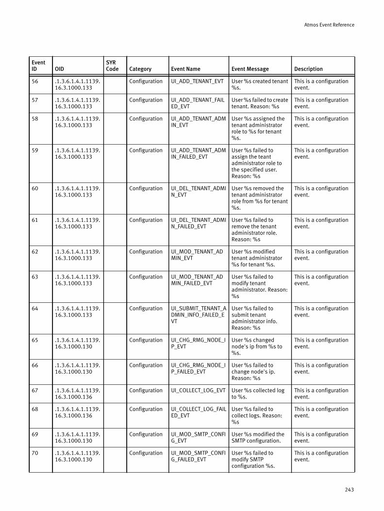
Atmos Event Reference
56 .1.3.6.1.4.1.1139.16.3.1000.133
Configuration UI_ADD_TENANT_EVT User %s created tenant %s.
This is a configuration event.
57 .1.3.6.1.4.1.1139.16.3.1000.133
Configuration UI_ADD_TENANT_FAILED_EVT
User %s failed to create tenant. Reason: %s
This is a configuration event.
58 .1.3.6.1.4.1.1139.16.3.1000.133
Configuration UI_ADD_TENANT_ADMIN_EVT
User %s assigned the tenant administrator role to %s for tenant %s.
This is a configuration event.
59 .1.3.6.1.4.1.1139.16.3.1000.133
Configuration UI_ADD_TENANT_ADMIN_FAILED_EVT
User %s failed to assign the teant administrator role to the specified user. Reason: %s
This is a configuration event.
60 .1.3.6.1.4.1.1139.16.3.1000.133
Configuration UI_DEL_TENANT_ADMIN_EVT
User %s removed the tenant administrator role from %s for tenant %s.
This is a configuration event.
61 .1.3.6.1.4.1.1139.16.3.1000.133
Configuration UI_DEL_TENANT_ADMIN_FAILED_EVT
User %s failed to remove the tenant administrator role. Reason: %s
This is a configuration event.
62 .1.3.6.1.4.1.1139.16.3.1000.133
Configuration UI_MOD_TENANT_ADMIN_EVT
User %s modified tenant administrator %s for tenant %s.
This is a configuration event.
63 .1.3.6.1.4.1.1139.16.3.1000.133
Configuration UI_MOD_TENANT_ADMIN_FAILED_EVT
User %s failed to modify tenant administrator. Reason: %s
This is a configuration event.
64 .1.3.6.1.4.1.1139.16.3.1000.133
Configuration UI_SUBMIT_TENANT_ADMIN_INFO_FAILED_EVT
User %s failed to submit tenant administrator info. Reason: %s
This is a configuration event.
65 .1.3.6.1.4.1.1139.16.3.1000.130
Configuration UI_CHG_RMG_NODE_IP_EVT
User %s changed node's ip from %s to %s.
This is a configuration event.
66 .1.3.6.1.4.1.1139.16.3.1000.130
Configuration UI_CHG_RMG_NODE_IP_FAILED_EVT
User %s failed to change node's ip. Reason: %s
This is a configuration event.
67 .1.3.6.1.4.1.1139.16.3.1000.136
Configuration UI_COLLECT_LOG_EVT User %s collected log to %s.
This is a configuration event.
68 .1.3.6.1.4.1.1139.16.3.1000.136
Configuration UI_COLLECT_LOG_FAILED_EVT
User %s failed to collect logs. Reason: %s
This is a configuration event.
69 .1.3.6.1.4.1.1139.16.3.1000.130
Configuration UI_MOD_SMTP_CONFIG_EVT
User %s modified the SMTP configuration.
This is a configuration event.
70 .1.3.6.1.4.1.1139.16.3.1000.130
Configuration UI_MOD_SMTP_CONFIG_FAILED_EVT
User %s failed to modify SMTP configuration %s.
This is a configuration event.
Event ID OID
SYR Code Category Event Name Event Message Description
243
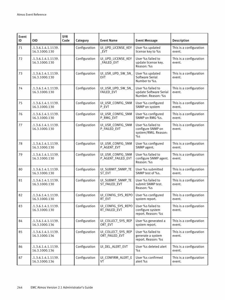
Atmos Event Reference
71 .1.3.6.1.4.1.1139.16.3.1000.130
Configuration UI_UPD_LICENSE_KEY_EVT
User %s updated license key to %s
This is a configuration event.
72 .1.3.6.1.4.1.1139.16.3.1000.130
Configuration UI_UPD_LICENSE_KEY_FAILED_EVT
User %s failed to update license key. Reason: %s
This is a configuration event.
73 .1.3.6.1.4.1.1139.16.3.1000.130
Configuration UI_USR_UPD_SW_SN_EVT
User %s updated Software Serial Number to %s.
This is a configuration event.
74 .1.3.6.1.4.1.1139.16.3.1000.130
Configuration UI_USR_UPD_SW_SN_FAILED_EVT
User %s failed to update Software Serial Number. Reason: %s
This is a configuration event.
75 .1.3.6.1.4.1.1139.16.3.1000.130
Configuration UI_USR_CONFIG_SNMP_EVT
User %s configured SNMP on system
This is a configuration event.
76 .1.3.6.1.4.1.1139.16.3.1000.130
Configuration UI_USR_CONFIG_SNMP_RMG_EVT
User %s configured SNMP on RMG %s.
This is a configuration event.
77 .1.3.6.1.4.1.1139.16.3.1000.130
Configuration UI_USR_CONFIG_SNMP_FAILED_EVT
User %s failed to configure SNMP on system/RMG. Reason: %s
This is a configuration event.
78 .1.3.6.1.4.1.1139.16.3.1000.130
Configuration UI_USR_CONFIG_SNMP_AGENT_EVT
User %s configured SNMP agent.
This is a configuration event.
79 .1.3.6.1.4.1.1139.16.3.1000.130
Configuration UI_USR_CONFIG_SNMP_AGENT_FAILED_EVT
User %s failed to configure SNMP agent. Reason: %s
This is a configuration event.
80 .1.3.6.1.4.1.1139.16.3.1000.130
Configuration UI_SUBMIT_SNMP_TEST_EVT
User %s submitted SNMP test of %s.
This is a configuration event.
81 .1.3.6.1.4.1.1139.16.3.1000.130
Configuration UI_SUBMIT_SNMP_TEST_FAILED_EVT
User %s failed to submit SNMP test. Reason: %s
This is a configuration event.
82 .1.3.6.1.4.1.1139.16.3.1000.130
Configuration UI_CONFIG_SYS_REPORT_EVT
User %s configured system report.
This is a configuration event.
83 .1.3.6.1.4.1.1139.16.3.1000.130
Configuration UI_CONFIG_SYS_REPORT_FAILED_EVT
User %s failed to configure system report. Reason: %s
This is a configuration event.
84 .1.3.6.1.4.1.1139.16.3.1000.136
Configuration UI_COLLECT_SYS_REPORT_EVT
User %s generated a system report.
This is a configuration event.
85 .1.3.6.1.4.1.1139.16.3.1000.136
Configuration UI_COLLECT_SYS_REPORT_FAILED_EVT
User %s failed to generate a system report. Reason: %s
This is a configuration event.
86 .1.3.6.1.4.1.1139.16.3.1000.136
Configuration UI_DEL_ALERT_EVT User %s deleted alert %s
This is a configuration event.
87 .1.3.6.1.4.1.1139.16.3.1000.136
Configuration UI_CONFIRM_ALERT_EVT
User %s confirmed alert %s
This is a configuration event.
Event ID OID
SYR Code Category Event Name Event Message Description
244 EMC Atmos Version 2.1 Administrator’s Guide
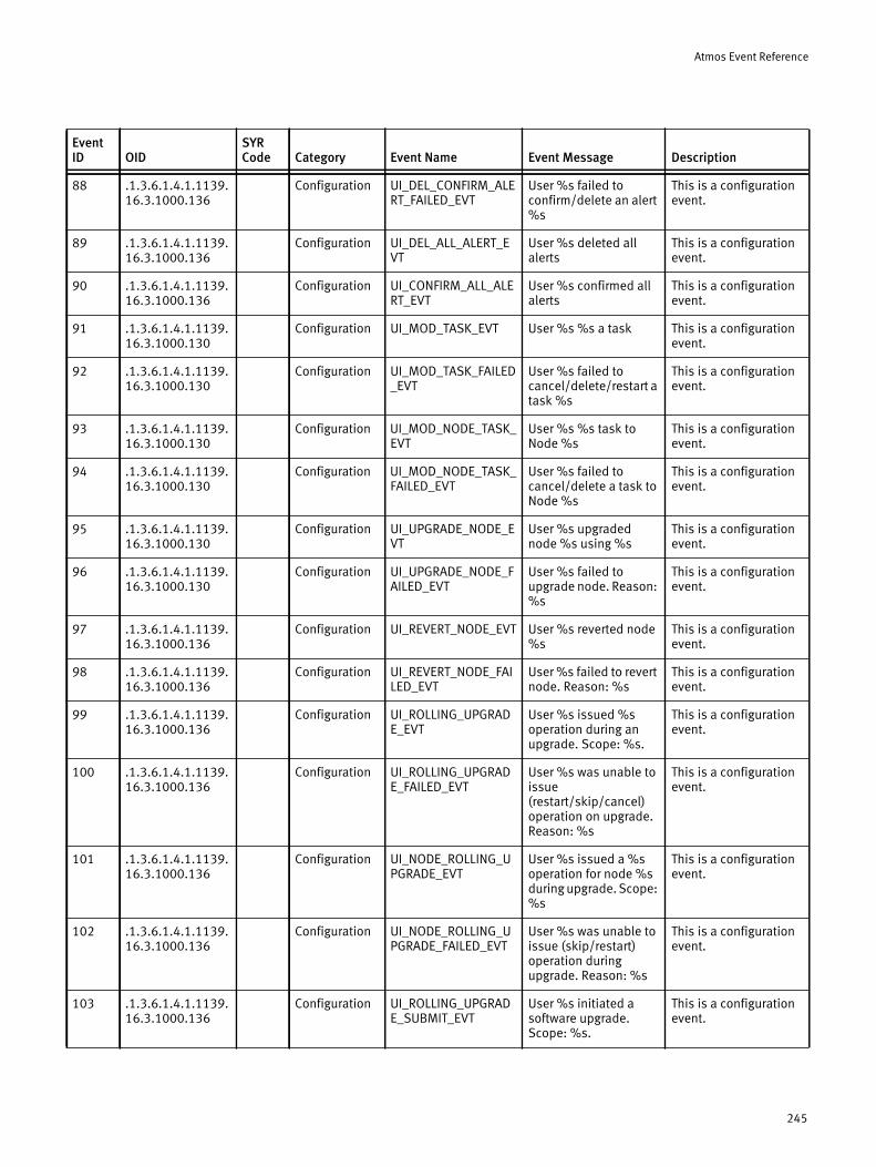
Atmos Event Reference
88 .1.3.6.1.4.1.1139.16.3.1000.136
Configuration UI_DEL_CONFIRM_ALERT_FAILED_EVT
User %s failed to confirm/delete an alert %s
This is a configuration event.
89 .1.3.6.1.4.1.1139.16.3.1000.136
Configuration UI_DEL_ALL_ALERT_EVT
User %s deleted all alerts
This is a configuration event.
90 .1.3.6.1.4.1.1139.16.3.1000.136
Configuration UI_CONFIRM_ALL_ALERT_EVT
User %s confirmed all alerts
This is a configuration event.
91 .1.3.6.1.4.1.1139.16.3.1000.130
Configuration UI_MOD_TASK_EVT User %s %s a task This is a configuration event.
92 .1.3.6.1.4.1.1139.16.3.1000.130
Configuration UI_MOD_TASK_FAILED_EVT
User %s failed to cancel/delete/restart a task %s
This is a configuration event.
93 .1.3.6.1.4.1.1139.16.3.1000.130
Configuration UI_MOD_NODE_TASK_EVT
User %s %s task to Node %s
This is a configuration event.
94 .1.3.6.1.4.1.1139.16.3.1000.130
Configuration UI_MOD_NODE_TASK_FAILED_EVT
User %s failed to cancel/delete a task to Node %s
This is a configuration event.
95 .1.3.6.1.4.1.1139.16.3.1000.130
Configuration UI_UPGRADE_NODE_EVT
User %s upgraded node %s using %s
This is a configuration event.
96 .1.3.6.1.4.1.1139.16.3.1000.130
Configuration UI_UPGRADE_NODE_FAILED_EVT
User %s failed to upgrade node. Reason: %s
This is a configuration event.
97 .1.3.6.1.4.1.1139.16.3.1000.136
Configuration UI_REVERT_NODE_EVT User %s reverted node %s
This is a configuration event.
98 .1.3.6.1.4.1.1139.16.3.1000.136
Configuration UI_REVERT_NODE_FAILED_EVT
User %s failed to revert node. Reason: %s
This is a configuration event.
99 .1.3.6.1.4.1.1139.16.3.1000.136
Configuration UI_ROLLING_UPGRADE_EVT
User %s issued %s operation during an upgrade. Scope: %s.
This is a configuration event.
100 .1.3.6.1.4.1.1139.16.3.1000.136
Configuration UI_ROLLING_UPGRADE_FAILED_EVT
User %s was unable to issue (restart/skip/cancel) operation on upgrade. Reason: %s
This is a configuration event.
101 .1.3.6.1.4.1.1139.16.3.1000.136
Configuration UI_NODE_ROLLING_UPGRADE_EVT
User %s issued a %s operation for node %s during upgrade. Scope: %s
This is a configuration event.
102 .1.3.6.1.4.1.1139.16.3.1000.136
Configuration UI_NODE_ROLLING_UPGRADE_FAILED_EVT
User %s was unable to issue (skip/restart) operation during upgrade. Reason: %s
This is a configuration event.
103 .1.3.6.1.4.1.1139.16.3.1000.136
Configuration UI_ROLLING_UPGRADE_SUBMIT_EVT
User %s initiated a software upgrade. Scope: %s.
This is a configuration event.
Event ID OID
SYR Code Category Event Name Event Message Description
245
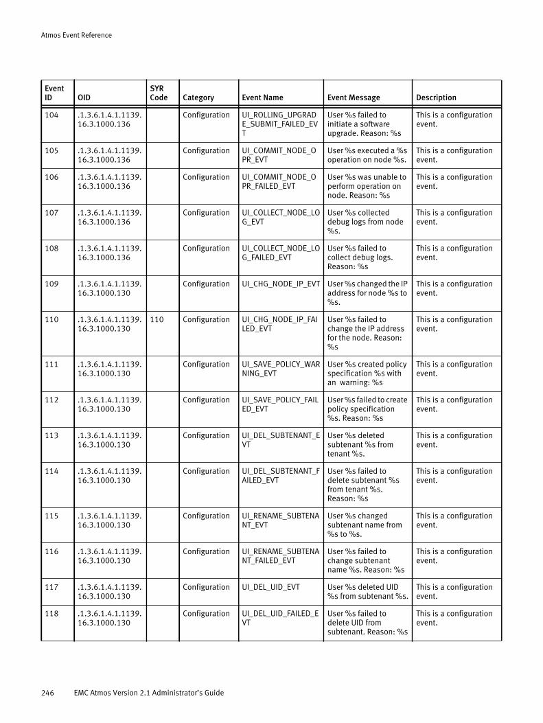
Atmos Event Reference
104 .1.3.6.1.4.1.1139.16.3.1000.136
Configuration UI_ROLLING_UPGRADE_SUBMIT_FAILED_EVT
User %s failed to initiate a software upgrade. Reason: %s
This is a configuration event.
105 .1.3.6.1.4.1.1139.16.3.1000.136
Configuration UI_COMMIT_NODE_OPR_EVT
User %s executed a %s operation on node %s.
This is a configuration event.
106 .1.3.6.1.4.1.1139.16.3.1000.136
Configuration UI_COMMIT_NODE_OPR_FAILED_EVT
User %s was unable to perform operation on node. Reason: %s
This is a configuration event.
107 .1.3.6.1.4.1.1139.16.3.1000.136
Configuration UI_COLLECT_NODE_LOG_EVT
User %s collected debug logs from node %s.
This is a configuration event.
108 .1.3.6.1.4.1.1139.16.3.1000.136
Configuration UI_COLLECT_NODE_LOG_FAILED_EVT
User %s failed to collect debug logs. Reason: %s
This is a configuration event.
109 .1.3.6.1.4.1.1139.16.3.1000.130
Configuration UI_CHG_NODE_IP_EVT User %s changed the IP address for node %s to %s.
This is a configuration event.
110 .1.3.6.1.4.1.1139.16.3.1000.130
110 Configuration UI_CHG_NODE_IP_FAILED_EVT
User %s failed to change the IP address for the node. Reason: %s
This is a configuration event.
111 .1.3.6.1.4.1.1139.16.3.1000.130
Configuration UI_SAVE_POLICY_WARNING_EVT
User %s created policy specification %s with an warning: %s
This is a configuration event.
112 .1.3.6.1.4.1.1139.16.3.1000.130
Configuration UI_SAVE_POLICY_FAILED_EVT
User %s failed to create policy specification %s. Reason: %s
This is a configuration event.
113 .1.3.6.1.4.1.1139.16.3.1000.130
Configuration UI_DEL_SUBTENANT_EVT
User %s deleted subtenant %s from tenant %s.
This is a configuration event.
114 .1.3.6.1.4.1.1139.16.3.1000.130
Configuration UI_DEL_SUBTENANT_FAILED_EVT
User %s failed to delete subtenant %s from tenant %s. Reason: %s
This is a configuration event.
115 .1.3.6.1.4.1.1139.16.3.1000.130
Configuration UI_RENAME_SUBTENANT_EVT
User %s changed subtenant name from %s to %s.
This is a configuration event.
116 .1.3.6.1.4.1.1139.16.3.1000.130
Configuration UI_RENAME_SUBTENANT_FAILED_EVT
User %s failed to change subtenant name %s. Reason: %s
This is a configuration event.
117 .1.3.6.1.4.1.1139.16.3.1000.130
Configuration UI_DEL_UID_EVT User %s deleted UID %s from subtenant %s.
This is a configuration event.
118 .1.3.6.1.4.1.1139.16.3.1000.130
Configuration UI_DEL_UID_FAILED_EVT
User %s failed to delete UID from subtenant. Reason: %s
This is a configuration event.
Event ID OID
SYR Code Category Event Name Event Message Description
246 EMC Atmos Version 2.1 Administrator’s Guide
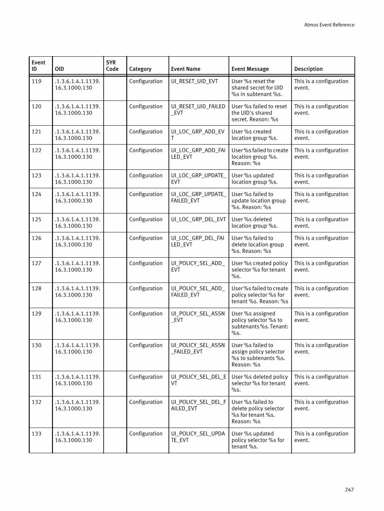
Atmos Event Reference
119 .1.3.6.1.4.1.1139.16.3.1000.130
Configuration UI_RESET_UID_EVT User %s reset the shared secret for UID %s in subtenant %s.
This is a configuration event.
120 .1.3.6.1.4.1.1139.16.3.1000.130
Configuration UI_RESET_UID_FAILED_EVT
User %s failed to reset the UID's shared secret. Reason: %s
This is a configuration event.
121 .1.3.6.1.4.1.1139.16.3.1000.130
Configuration UI_LOC_GRP_ADD_EVT
User %s created location group %s.
This is a configuration event.
122 .1.3.6.1.4.1.1139.16.3.1000.130
Configuration UI_LOC_GRP_ADD_FAILED_EVT
User %s failed to create location group %s. Reason: %s
This is a configuration event.
123 .1.3.6.1.4.1.1139.16.3.1000.130
Configuration UI_LOC_GRP_UPDATE_EVT
User %s updated location group %s.
This is a configuration event.
124 .1.3.6.1.4.1.1139.16.3.1000.130
Configuration UI_LOC_GRP_UPDATE_FAILED_EVT
User %s failed to update location group %s. Reason: %s
This is a configuration event.
125 .1.3.6.1.4.1.1139.16.3.1000.130
Configuration UI_LOC_GRP_DEL_EVT User %s deleted location group %s.
This is a configuration event.
126 .1.3.6.1.4.1.1139.16.3.1000.130
Configuration UI_LOC_GRP_DEL_FAILED_EVT
User %s failed to delete location group %s. Reason: %s
This is a configuration event.
127 .1.3.6.1.4.1.1139.16.3.1000.130
Configuration UI_POLICY_SEL_ADD_EVT
User %s created policy selector %s for tenant %s.
This is a configuration event.
128 .1.3.6.1.4.1.1139.16.3.1000.130
Configuration UI_POLICY_SEL_ADD_FAILED_EVT
User %s failed to create policy selector %s for tenant %s. Reason: %s
This is a configuration event.
129 .1.3.6.1.4.1.1139.16.3.1000.130
Configuration UI_POLICY_SEL_ASSN_EVT
User %s assigned policy selector %s to subtenants %s. Tenant: %s.
This is a configuration event.
130 .1.3.6.1.4.1.1139.16.3.1000.130
Configuration UI_POLICY_SEL_ASSN_FAILED_EVT
User %s failed to assign policy selector %s to subtenants %s. Reason: %s
This is a configuration event.
131 .1.3.6.1.4.1.1139.16.3.1000.130
Configuration UI_POLICY_SEL_DEL_EVT
User %s deleted policy selector %s for tenant %s.
This is a configuration event.
132 .1.3.6.1.4.1.1139.16.3.1000.130
Configuration UI_POLICY_SEL_DEL_FAILED_EVT
User %s failed to delete policy selector %s for tenant %s. Reason: %s
This is a configuration event.
133 .1.3.6.1.4.1.1139.16.3.1000.130
Configuration UI_POLICY_SEL_UPDATE_EVT
User %s updated policy selector %s for tenant %s.
This is a configuration event.
Event ID OID
SYR Code Category Event Name Event Message Description
247
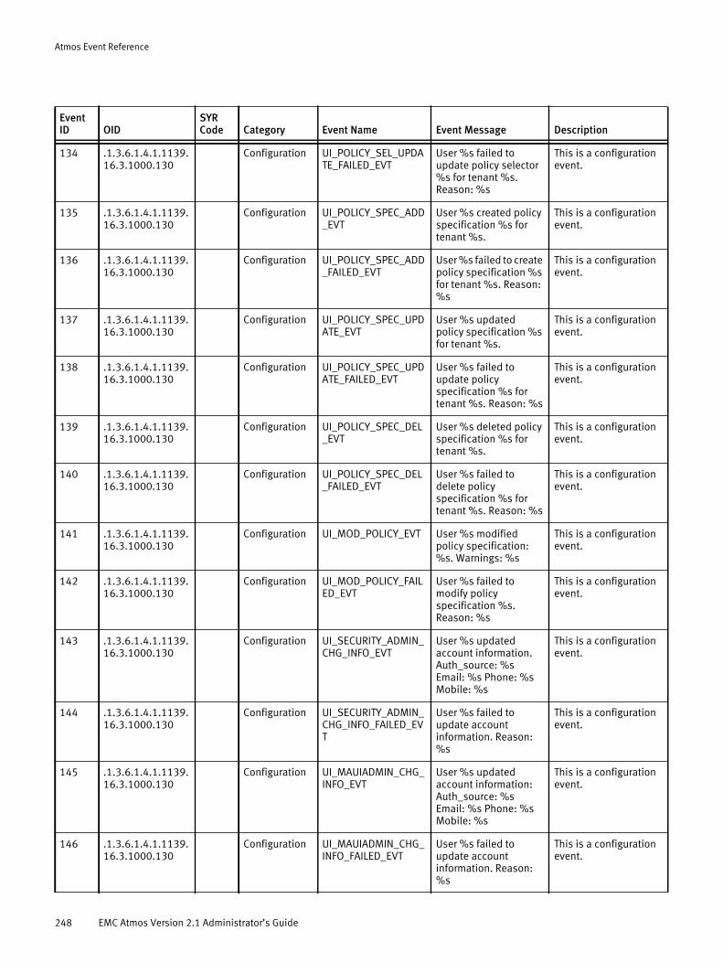
Atmos Event Reference
134 .1.3.6.1.4.1.1139.16.3.1000.130
Configuration UI_POLICY_SEL_UPDATE_FAILED_EVT
User %s failed to update policy selector %s for tenant %s. Reason: %s
This is a configuration event.
135 .1.3.6.1.4.1.1139.16.3.1000.130
Configuration UI_POLICY_SPEC_ADD_EVT
User %s created policy specification %s for tenant %s.
This is a configuration event.
136 .1.3.6.1.4.1.1139.16.3.1000.130
Configuration UI_POLICY_SPEC_ADD_FAILED_EVT
User %s failed to create policy specification %s for tenant %s. Reason: %s
This is a configuration event.
137 .1.3.6.1.4.1.1139.16.3.1000.130
Configuration UI_POLICY_SPEC_UPDATE_EVT
User %s updated policy specification %s for tenant %s.
This is a configuration event.
138 .1.3.6.1.4.1.1139.16.3.1000.130
Configuration UI_POLICY_SPEC_UPDATE_FAILED_EVT
User %s failed to update policy specification %s for tenant %s. Reason: %s
This is a configuration event.
139 .1.3.6.1.4.1.1139.16.3.1000.130
Configuration UI_POLICY_SPEC_DEL_EVT
User %s deleted policy specification %s for tenant %s.
This is a configuration event.
140 .1.3.6.1.4.1.1139.16.3.1000.130
Configuration UI_POLICY_SPEC_DEL_FAILED_EVT
User %s failed to delete policy specification %s for tenant %s. Reason: %s
This is a configuration event.
141 .1.3.6.1.4.1.1139.16.3.1000.130
Configuration UI_MOD_POLICY_EVT User %s modified policy specification: %s. Warnings: %s
This is a configuration event.
142 .1.3.6.1.4.1.1139.16.3.1000.130
Configuration UI_MOD_POLICY_FAILED_EVT
User %s failed to modify policy specification %s. Reason: %s
This is a configuration event.
143 .1.3.6.1.4.1.1139.16.3.1000.130
Configuration UI_SECURITY_ADMIN_CHG_INFO_EVT
User %s updated account information. Auth_source: %s Email: %s Phone: %s Mobile: %s
This is a configuration event.
144 .1.3.6.1.4.1.1139.16.3.1000.130
Configuration UI_SECURITY_ADMIN_CHG_INFO_FAILED_EVT
User %s failed to update account information. Reason: %s
This is a configuration event.
145 .1.3.6.1.4.1.1139.16.3.1000.130
Configuration UI_MAUIADMIN_CHG_INFO_EVT
User %s updated account information: Auth_source: %s Email: %s Phone: %s Mobile: %s
This is a configuration event.
146 .1.3.6.1.4.1.1139.16.3.1000.130
Configuration UI_MAUIADMIN_CHG_INFO_FAILED_EVT
User %s failed to update account information. Reason: %s
This is a configuration event.
Event ID OID
SYR Code Category Event Name Event Message Description
248 EMC Atmos Version 2.1 Administrator’s Guide

Atmos Event Reference
147 .1.3.6.1.4.1.1139.16.3.1000.130
Configuration UI_MAUIADMIN_CFG_ADD_SUCCESS_EVT
User %s successfully added %s configuration for %s.
This is a configuration event.
148 .1.3.6.1.4.1.1139.16.3.1000.130
Configuration UI_MAUIADMIN_CFG_ADD_FAILED_EVT
User %s failed to add %s configuration for %s.
This is a configuration event.
149 .1.3.6.1.4.1.1139.16.3.1000.130
Configuration UI_MAUIADMIN_CFG_MOD_SUCCESS_EVT
User %s successfully modified %s configuration for %s.
This is a configuration event.
150 .1.3.6.1.4.1.1139.16.3.1000.130
Configuration UI_MAUIADMIN_CFG_MOD_FAILED_EVT
User %s failed to modify %s configuration for %s.
This is a configuration event.
151 .1.3.6.1.4.1.1139.16.3.1000.130
Configuration UI_MAUIADMIN_CFG_DELETE_SUCCESS_EVT
User %s successfully deleted %s configuration for %s.
This is a configuration event.
152 .1.3.6.1.4.1.1139.16.3.1000.130
Configuration UI_MAUIADMIN_CFG_DELETE_FAILED_EVT
User %s failed to delete %s configuration for %s.
This is a configuration event.
153 .1.3.6.1.4.1.1139.16.3.1000.136
Upgrade UI_MAUIADMIN_UPGRADE_UPLOAD_START_EVT
User %s successfully started uploading upgrade software %s.
This is a upgrade operation event.
154 .1.3.6.1.4.1.1139.16.3.1000.136
Upgrade UI_MAUIADMIN_UPGRADE_UPLOAD_SUCCESS_EVT
User %s successfully uploaded %s in preparation for software upgrade.
This is a upgrade operation event.
155 .1.3.6.1.4.1.1139.16.3.1000.136
Upgrade UI_MAUIADMIN_UPGRADE_UPLOAD_FAILED_EVT
User %s failed to upload upgrade software %s.
This is a upgrade operation event.
156 .1.3.6.1.4.1.1139.16.3.1000.136
Upgrade UI_MAUIADMIN_UPGRADE_PREPARE_START_EVT
User %s successfully initiated a prepare operation for a software upgrade. Preparing %s.
This is a upgrade operation event.
157 .1.3.6.1.4.1.1139.16.3.1000.136
Upgrade UI_MAUIADMIN_UPGRADE_PREPARE_SUCCESS_EVT
User %s successfully prepared %s for software upgrading.
This is a upgrade operation event.
158 .1.3.6.1.4.1.1139.16.3.1000.136
Upgrade UI_MAUIADMIN_UPGRADE_PREPARE_FAILED_EVT
User %s failed to prepare %s for software upgrade. Reason: %s
This is a upgrade operation event.
159 .1.3.6.1.4.1.1139.16.3.1000.136
Upgrade UI_MAUIADMIN_UPGRADE_APPLY_START_EVT
User %s successfully initiated the apply operation for software upgrading on RMG %s.
This is a upgrade operation event.
160 .1.3.6.1.4.1.1139.16.3.1000.136
Upgrade UI_MAUIADMIN_UPGRADE_APPLY_SUCCESS_EVT
User %s successfully upgraded the software on RMG %s.
This is a upgrade operation event.
Event ID OID
SYR Code Category Event Name Event Message Description
249
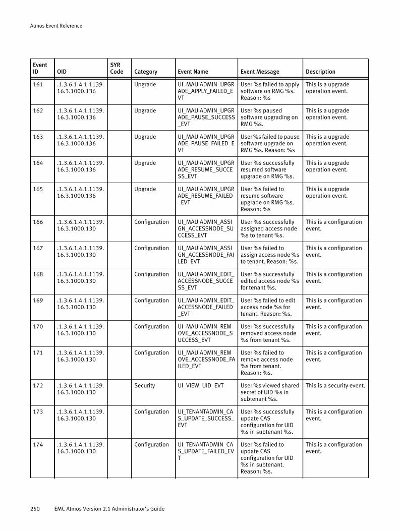
Atmos Event Reference
161 .1.3.6.1.4.1.1139.16.3.1000.136
Upgrade UI_MAUIADMIN_UPGRADE_APPLY_FAILED_EVT
User %s failed to apply software on RMG %s. Reason: %s
This is a upgrade operation event.
162 .1.3.6.1.4.1.1139.16.3.1000.136
Upgrade UI_MAUIADMIN_UPGRADE_PAUSE_SUCCESS_EVT
User %s paused software upgrading on RMG %s.
This is a upgrade operation event.
163 .1.3.6.1.4.1.1139.16.3.1000.136
Upgrade UI_MAUIADMIN_UPGRADE_PAUSE_FAILED_EVT
User %s failed to pause software upgrade on RMG %s. Reason: %s
This is a upgrade operation event.
164 .1.3.6.1.4.1.1139.16.3.1000.136
Upgrade UI_MAUIADMIN_UPGRADE_RESUME_SUCCESS_EVT
User %s successfully resumed software upgrade on RMG %s.
This is a upgrade operation event.
165 .1.3.6.1.4.1.1139.16.3.1000.136
Upgrade UI_MAUIADMIN_UPGRADE_RESUME_FAILED_EVT
User %s failed to resume software upgrade on RMG %s. Reason: %s
This is a upgrade operation event.
166 .1.3.6.1.4.1.1139.16.3.1000.130
Configuration UI_MAUIADMIN_ASSIGN_ACCESSNODE_SUCCESS_EVT
User %s successfully assigned access node %s to tenant %s.
This is a configuration event.
167 .1.3.6.1.4.1.1139.16.3.1000.130
Configuration UI_MAUIADMIN_ASSIGN_ACCESSNODE_FAILED_EVT
User %s failed to assign access node %s to tenant. Reason: %s.
This is a configuration event.
168 .1.3.6.1.4.1.1139.16.3.1000.130
Configuration UI_MAUIADMIN_EDIT_ACCESSNODE_SUCCESS_EVT
User %s successfully edited access node %s for tenant %s.
This is a configuration event.
169 .1.3.6.1.4.1.1139.16.3.1000.130
Configuration UI_MAUIADMIN_EDIT_ACCESSNODE_FAILED_EVT
User %s failed to edit access node %s for tenant. Reason: %s.
This is a configuration event.
170 .1.3.6.1.4.1.1139.16.3.1000.130
Configuration UI_MAUIADMIN_REMOVE_ACCESSNODE_SUCCESS_EVT
User %s successfully removed access node %s from tenant %s.
This is a configuration event.
171 .1.3.6.1.4.1.1139.16.3.1000.130
Configuration UI_MAUIADMIN_REMOVE_ACCESSNODE_FAILED_EVT
User %s failed to remove access node %s from tenant. Reason: %s.
This is a configuration event.
172 .1.3.6.1.4.1.1139.16.3.1000.130
Security UI_VIEW_UID_EVT User %s viewed shared secret of UID %s in subtenant %s.
This is a security event.
173 .1.3.6.1.4.1.1139.16.3.1000.130
Configuration UI_TENANTADMIN_CAS_UPDATE_SUCCESS_EVT
User %s successfully update CAS configuration for UID %s in subtenant %s.
This is a configuration event.
174 .1.3.6.1.4.1.1139.16.3.1000.130
Configuration UI_TENANTADMIN_CAS_UPDATE_FAILED_EVT
User %s failed to update CAS configuration for UID %s in subtenant. Reason: %s.
This is a configuration event.
Event ID OID
SYR Code Category Event Name Event Message Description
250 EMC Atmos Version 2.1 Administrator’s Guide
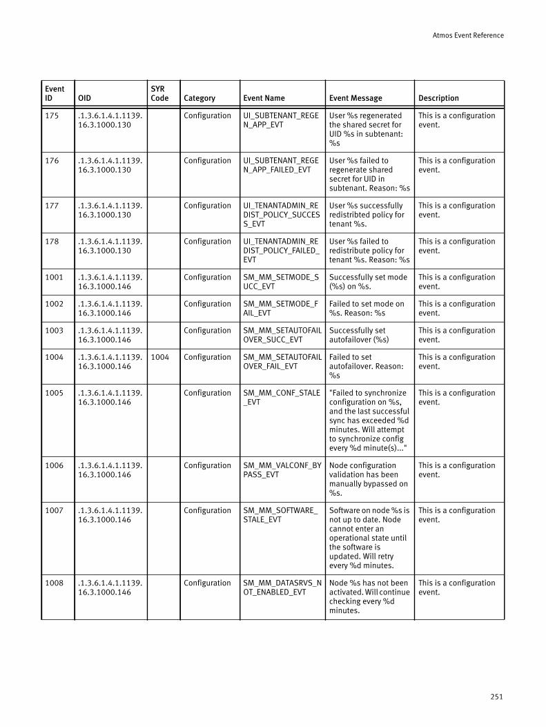
Atmos Event Reference
175 .1.3.6.1.4.1.1139.16.3.1000.130
Configuration UI_SUBTENANT_REGEN_APP_EVT
User %s regenerated the shared secret for UID %s in subtenant: %s
This is a configuration event.
176 .1.3.6.1.4.1.1139.16.3.1000.130
Configuration UI_SUBTENANT_REGEN_APP_FAILED_EVT
User %s failed to regenerate shared secret for UID in subtenant. Reason: %s
This is a configuration event.
177 .1.3.6.1.4.1.1139.16.3.1000.130
Configuration UI_TENANTADMIN_REDIST_POLICY_SUCCESS_EVT
User %s successfully redistribted policy for tenant %s.
This is a configuration event.
178 .1.3.6.1.4.1.1139.16.3.1000.130
Configuration UI_TENANTADMIN_REDIST_POLICY_FAILED_EVT
User %s failed to redistribute policy for tenant %s. Reason: %s
This is a configuration event.
1001 .1.3.6.1.4.1.1139.16.3.1000.146
Configuration SM_MM_SETMODE_SUCC_EVT
Successfully set mode (%s) on %s.
This is a configuration event.
1002 .1.3.6.1.4.1.1139.16.3.1000.146
Configuration SM_MM_SETMODE_FAIL_EVT
Failed to set mode on %s. Reason: %s
This is a configuration event.
1003 .1.3.6.1.4.1.1139.16.3.1000.146
Configuration SM_MM_SETAUTOFAILOVER_SUCC_EVT
Successfully set autofailover (%s)
This is a configuration event.
1004 .1.3.6.1.4.1.1139.16.3.1000.146
1004 Configuration SM_MM_SETAUTOFAILOVER_FAIL_EVT
Failed to set autofailover. Reason: %s
This is a configuration event.
1005 .1.3.6.1.4.1.1139.16.3.1000.146
Configuration SM_MM_CONF_STALE_EVT
"Failed to synchronize configuration on %s, and the last successful sync has exceeded %d minutes. Will attempt to synchronize config every %d minute(s)..."
This is a configuration event.
1006 .1.3.6.1.4.1.1139.16.3.1000.146
Configuration SM_MM_VALCONF_BYPASS_EVT
Node configuration validation has been manually bypassed on %s.
This is a configuration event.
1007 .1.3.6.1.4.1.1139.16.3.1000.146
Configuration SM_MM_SOFTWARE_STALE_EVT
Software on node %s is not up to date. Node cannot enter an operational state until the software is updated. Will retry every %d minutes.
This is a configuration event.
1008 .1.3.6.1.4.1.1139.16.3.1000.146
Configuration SM_MM_DATASRVS_NOT_ENABLED_EVT
Node %s has not been activated. Will continue checking every %d minutes.
This is a configuration event.
Event ID OID
SYR Code Category Event Name Event Message Description
251
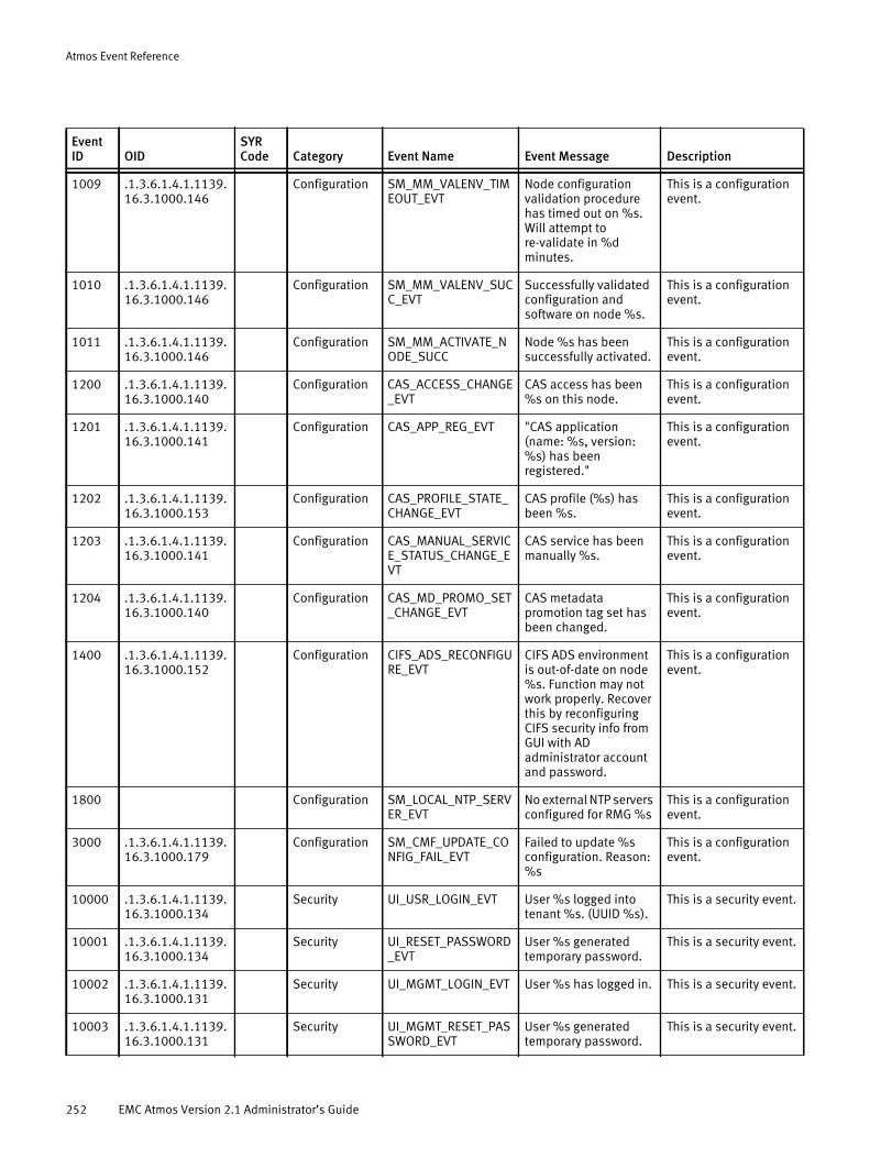
Atmos Event Reference
1009 .1.3.6.1.4.1.1139.16.3.1000.146
Configuration SM_MM_VALENV_TIMEOUT_EVT
Node configuration validation procedure has timed out on %s. Will attempt to re-validate in %d minutes.
This is a configuration event.
1010 .1.3.6.1.4.1.1139.16.3.1000.146
Configuration SM_MM_VALENV_SUCC_EVT
Successfully validated configuration and software on node %s.
This is a configuration event.
1011 .1.3.6.1.4.1.1139.16.3.1000.146
Configuration SM_MM_ACTIVATE_NODE_SUCC
Node %s has been successfully activated.
This is a configuration event.
1200 .1.3.6.1.4.1.1139.16.3.1000.140
Configuration CAS_ACCESS_CHANGE_EVT
CAS access has been %s on this node.
This is a configuration event.
1201 .1.3.6.1.4.1.1139.16.3.1000.141
Configuration CAS_APP_REG_EVT "CAS application (name: %s, version: %s) has been registered."
This is a configuration event.
1202 .1.3.6.1.4.1.1139.16.3.1000.153
Configuration CAS_PROFILE_STATE_CHANGE_EVT
CAS profile (%s) has been %s.
This is a configuration event.
1203 .1.3.6.1.4.1.1139.16.3.1000.141
Configuration CAS_MANUAL_SERVICE_STATUS_CHANGE_EVT
CAS service has been manually %s.
This is a configuration event.
1204 .1.3.6.1.4.1.1139.16.3.1000.140
Configuration CAS_MD_PROMO_SET_CHANGE_EVT
CAS metadata promotion tag set has been changed.
This is a configuration event.
1400 .1.3.6.1.4.1.1139.16.3.1000.152
Configuration CIFS_ADS_RECONFIGURE_EVT
CIFS ADS environment is out-of-date on node %s. Function may not work properly. Recover this by reconfiguring CIFS security info from GUI with AD administrator account and password.
This is a configuration event.
1800 Configuration SM_LOCAL_NTP_SERVER_EVT
No external NTP servers configured for RMG %s
This is a configuration event.
3000 .1.3.6.1.4.1.1139.16.3.1000.179
Configuration SM_CMF_UPDATE_CONFIG_FAIL_EVT
Failed to update %s configuration. Reason: %s
This is a configuration event.
10000 .1.3.6.1.4.1.1139.16.3.1000.134
Security UI_USR_LOGIN_EVT User %s logged into tenant %s. (UUID %s).
This is a security event.
10001 .1.3.6.1.4.1.1139.16.3.1000.134
Security UI_RESET_PASSWORD_EVT
User %s generated temporary password.
This is a security event.
10002 .1.3.6.1.4.1.1139.16.3.1000.131
Security UI_MGMT_LOGIN_EVT User %s has logged in. This is a security event.
10003 .1.3.6.1.4.1.1139.16.3.1000.131
Security UI_MGMT_RESET_PASSWORD_EVT
User %s generated temporary password.
This is a security event.
Event ID OID
SYR Code Category Event Name Event Message Description
252 EMC Atmos Version 2.1 Administrator’s Guide

Atmos Event Reference
10004 .1.3.6.1.4.1.1139.16.3.1000.134
Security UI_SYSADMIN_RESET_PASSWORD_EVT
User %s reset password.
This is a security event.
10005 .1.3.6.1.4.1.1139.16.3.1000.134
Security UI_SYSADMIN_RESET_PASSWORD_FAILED_EVT
User %s failed to reset password %s
This is a security event.
10006 .1.3.6.1.4.1.1139.16.3.1000.134
Security UI_TENANT_RESET_PASSWORD_EVT
Tenant %s UUID %s reset password.
This is a security event.
10007 .1.3.6.1.4.1.1139.16.3.1000.134
Security UI_TENANT_RESET_PASSWORD_FAILED_EVT
User %s failed to reset password %s
This is a security event.
10008 .1.3.6.1.4.1.1139.16.3.1000.131
Security UI_MAUIADMIN_RESET_PASSWORD_EVT
User %s reset his/her password.
This is a security event.
10009 .1.3.6.1.4.1.1139.16.3.1000.131
Security UI_MAUIADMIN_RESET_PASSWORD_FAILED_EVT
User %s failed to reset his/her password %s
This is a security event.
10010 .1.3.6.1.4.1.1139.16.3.1000.131
Security UI_SYSADMIN_LOGIN_EVT
User %s has logged in. This is a security event.
10011 .1.3.6.1.4.1.1139.16.3.1000.131
Security UI_SECURITY_ADMIN_LOGIN_EVT
User %s has logged in. This is a security event.
20000 .1.3.6.1.4.1.1139.16.3.1000.137
Upgrade SM_UPGRADE_START_EVT
Upgrade to software version %s has started.
This is an upgrade event.
20001 .1.3.6.1.4.1.1139.16.3.1000.137
Upgrade SM_UPGRADE_COMPL_EVT
Upgrade to software version %s has completed.
This is an upgrade event.
20002 .1.3.6.1.4.1.1139.16.3.1000.137
20002 Upgrade SM_UPGRADE_FAIL_EVT
Upgrade to software version %s failed on node %s.
This is an upgrade event.
20003 .1.3.6.1.4.1.1139.16.3.1000.137
Upgrade SM_UPGRADE_PAUSE_EVT
Upgrade to software version %s was paused on node %s.
This is an upgrade event.
20004 .1.3.6.1.4.1.1139.16.3.1000.137
Upgrade SM_UPGRADE_RESUME_EVT
Upgrade to software version %s was resumed on node %s.
This is an upgrade event.
20005 .1.3.6.1.4.1.1139.16.3.1000.137
Upgrade SM_PREPARE_START_EVT
Upgrade prepare step for version %s has started.
This is an upgrade event.
20006 .1.3.6.1.4.1.1139.16.3.1000.137
Upgrade SM_PREPARE_COMPL_EVT
Upgrade prepare step for version %s has completed.
This is an upgrade event.
20007 .1.3.6.1.4.1.1139.16.3.1000.137
20007 Upgrade SM_PREPARE_FAIL_EVT
Upgrade prepare step for version %s failed on node %s.
This is an upgrade event.
20008 .1.3.6.1.4.1.1139.16.3.1000.195
20008 Upgrade MDS_CONVERSION_PAUSED
MDS %s CC or BDB conversion task has been paused. Insufficient disk space to continue.
MDS conversion paused
Event ID OID
SYR Code Category Event Name Event Message Description
253
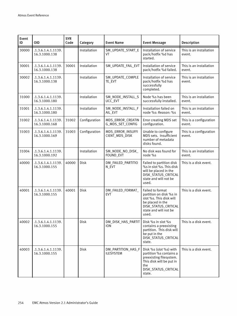
Atmos Event Reference
30000 .1.3.6.1.4.1.1139.16.3.1000.138
Installation SM_UPDATE_START_EVT
Installation of service pack/hotfix %d has started.
This is an installation event.
30001 .1.3.6.1.4.1.1139.16.3.1000.138
30001 Installation SM_UPDATE_FAIL_EVT Installation of service pack/hotfix %d failed.
This is an installation event.
30002 .1.3.6.1.4.1.1139.16.3.1000.138
Installation SM_UPDATE_COMPLETE_EVT
Installation of service pack/hotfix %d has successfully completed.
This is an installation event.
31000 .1.3.6.1.4.1.1139.16.3.1000.180
Installation SM_NODE_INSTALL_SUCC_EVT
Node %s has been successfully installed.
This is an installation event.
31001 .1.3.6.1.4.1.1139.16.3.1000.180
Installation SM_NODE_INSTALL_FAIL_EVT
Installation failed on node %s: Reason: %s
This is an installation event.
31002 .1.3.6.1.4.1.1139.16.3.1000.168
31002 Configuration MDS_ERROR_CREATING_MDS_SET_CONFIG
Error creating MDS set configuration.
This is a configuration event.
31003 .1.3.6.1.4.1.1139.16.3.1000.169
31003 Configuration MDS_ERROR_INSUFFICIENT_MDS_DISK
Unable to configure MDS sets. Insufficient number of metadata disks found.
This is a configuration event.
31004 .1.3.6.1.4.1.1139.16.3.1000.192
Installation SM_NODE_NO_DISK_FOUND_EVT
No disk was found for node %s
This is an installation event.
40000 .1.3.6.1.4.1.1139.16.3.1000.155
40000 Disk DM_FAILED_PARTITION_EVT
Failed to partition disk %s in slot %s. This disk will be placed in the DISK_STATUS_CRITICAL state and will not be used.
This is a disk event.
40001 .1.3.6.1.4.1.1139.16.3.1000.155
40001 Disk DM_FAILED_FORMAT_EVT
Failed to format partition on disk %s in slot %s. This disk will be placed in the DISK_STATUS_CRITICAL state and will not be used.
This is a disk event.
40002 .1.3.6.1.4.1.1139.16.3.1000.155
Disk DM_DISK_HAS_PARTITION
Disk %s in slot %s contains a preexisting partition. This disk will be put in the DISK_STATUS_CRITICAL state.
This is a disk event.
40003 .1.3.6.1.4.1.1139.16.3.1000.155
Disk DM_PARTITION_HAS_FILESYSTEM
Disk %s (slot %s) with partition %s contains a preexisting filesystem. This disk will be put in the DISK_STATUS_CRITICAL state.
This is a disk event.
Event ID OID
SYR Code Category Event Name Event Message Description
254 EMC Atmos Version 2.1 Administrator’s Guide
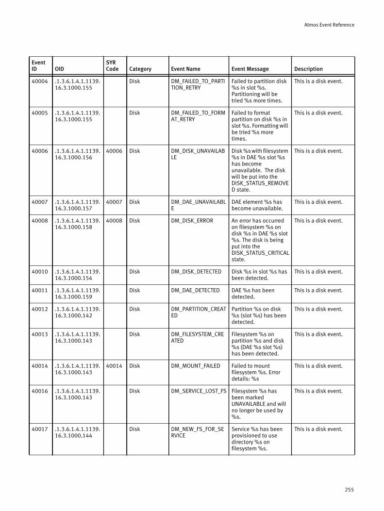
Atmos Event Reference
40004 .1.3.6.1.4.1.1139.16.3.1000.155
Disk DM_FAILED_TO_PARTITION_RETRY
Failed to partition disk %s in slot %s. Partitioning will be tried %s more times.
This is a disk event.
40005 .1.3.6.1.4.1.1139.16.3.1000.155
Disk DM_FAILED_TO_FORMAT_RETRY
Failed to format partition on disk %s in slot %s. Formatting will be tried %s more times.
This is a disk event.
40006 .1.3.6.1.4.1.1139.16.3.1000.156
40006 Disk DM_DISK_UNAVAILABLE
Disk %s with filesystem %s in DAE %s slot %s has become unavailable. The disk will be put into the DISK_STATUS_REMOVED state.
This is a disk event.
40007 .1.3.6.1.4.1.1139.16.3.1000.157
40007 Disk DM_DAE_UNAVAILABLE
DAE element %s has become unavailable.
This is a disk event.
40008 .1.3.6.1.4.1.1139.16.3.1000.158
40008 Disk DM_DISK_ERROR An error has occurred on filesystem %s on disk %s in DAE %s slot %s. The disk is being put into the DISK_STATUS_CRITICAL state.
This is a disk event.
40010 .1.3.6.1.4.1.1139.16.3.1000.154
Disk DM_DISK_DETECTED Disk %s in slot %s has been detected.
This is a disk event.
40011 .1.3.6.1.4.1.1139.16.3.1000.159
Disk DM_DAE_DETECTED DAE %s has been detected.
This is a disk event.
40012 .1.3.6.1.4.1.1139.16.3.1000.142
Disk DM_PARTITION_CREATED
Partition %s on disk %s (slot %s) has been detected.
This is a disk event.
40013 .1.3.6.1.4.1.1139.16.3.1000.143
Disk DM_FILESYSTEM_CREATED
Filesystem %s on partition %s and disk %s (DAE %s slot %s) has been detected.
This is a disk event.
40014 .1.3.6.1.4.1.1139.16.3.1000.143
40014 Disk DM_MOUNT_FAILED Failed to mount filesystem %s. Error details: %s
This is a disk event.
40016 .1.3.6.1.4.1.1139.16.3.1000.143
Disk DM_SERVICE_LOST_FS Filesystem %s has been marked UNAVAILABLE and will no longer be used by %s.
This is a disk event.
40017 .1.3.6.1.4.1.1139.16.3.1000.144
Disk DM_NEW_FS_FOR_SERVICE
Service %s has been provisioned to use directory %s on filesystem %s.
This is a disk event.
Event ID OID
SYR Code Category Event Name Event Message Description
255
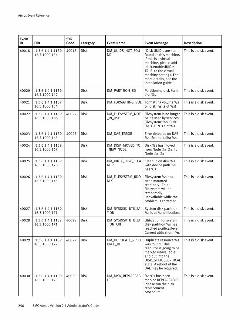
Atmos Event Reference
40018 .1.3.6.1.4.1.1139.16.3.1000.156
40018 Disk DM_UUIDS_NOT_FOUND
"Disk UUID's are not found on this machine. If this is a virtual machine, please add 'disk.enableUUID = TRUE' to the virtual machine settings. For more details, see the installation guide."
This is a disk event.
40020 .1.3.6.1.4.1.1139.16.3.1000.142
Disk DM_PARTITION_SD Partitioning disk %s in slot %s
This is a disk event.
40021 .1.3.6.1.4.1.1139.16.3.1000.154
Disk DM_FORMATTING_VOL Formatting volume %s on disk %s (slot %s)
This is a disk event.
40022 .1.3.6.1.4.1.1139.16.3.1000.166
40022 Disk DM_FILESYSTEM_NOT_IN_USE
Filesystem is no longer being used by services. Filesystem: %s Disk: %s DAE %s slot %s
This is a disk event.
40023 .1.3.6.1.4.1.1139.16.3.1000.165
40023 Disk DM_DAE_ERROR Error detected on DAE %s. Error details: %s.
This is a disk event.
40024 .1.3.6.1.4.1.1139.16.3.1000.167
Disk DM_DISK_MOVED_TO_NEW_NODE
Disk %s has moved from Node %s(%s) to Node %s(%s)
This is a disk event.
40025 .1.3.6.1.4.1.1139.16.3.1000.170
Disk DM_DIRTY_DISK_CLEANUP
Cleanup on disk %s with device path %s has %s
This is a disk event.
40026 .1.3.6.1.4.1.1139.16.3.1000.143
Disk DM_FILESYSTEM_RDONLY
Filesystem %s has been mounted read-only. This filesystem will be temporarily unavailable while the problem is corrected.
This is a disk event.
40027 .1.3.6.1.4.1.1139.16.3.1000.171
Disk DM_SYSDISK_UTILIZATION
System disk partition %s is at %s utilization.
This is a disk event.
40028 .1.3.6.1.4.1.1139.16.3.1000.171
40028 Disk DM_SYSDISK_UTILIZATION_CRIT
Utilization for system disk partition %s has reached a critical level. Current utilization: %s
This is a disk event.
40029 .1.3.6.1.4.1.1139.16.3.1000.172
40029 Disk DM_DUPLICATE_RESOURCE_ID
Duplicate resource %s was found. This resource is going to be marked unavailable and put into the DISK_STATUS_CRITICAL state. A reboot of the DAE may be required.
This is a disk event.
40030 .1.3.6.1.4.1.1139.16.3.1000.173
40030 Disk DM_DISK_REPLACEABLE
%s %s has been marked REPLACEABLE. Please run the disk replacement procedure.
This is a disk event.
Event ID OID
SYR Code Category Event Name Event Message Description
256 EMC Atmos Version 2.1 Administrator’s Guide

Atmos Event Reference
40031 .1.3.6.1.4.1.1139.16.3.1000.173
40031 Disk DM_DISK_NOT_REPLACEABLE
%s %s is no longer REPLACEABLE.
This is a disk event.
40032 .1.3.6.1.4.1.1139.16.3.1000.197
40032 Disk DM_FILESYSTEM_DEVICE_PATH_CHANGED
"Filesystem %s was found mounted on %s, but %s has changed to %s. The filesystem is being marked UNAVAILABLE until the problem is corrected."
This is a disk event.
40100 .1.3.6.1.4.1.1139.16.3.1000.161
Disk DISK_REC_PROG_EVT "On disk %s, %d objects were recovered."
This is a disk event.
40101 .1.3.6.1.4.1.1139.16.3.1000.161
Disk DISK_REC_START_EVT Disk Recovery has been started for disk %s.
This is a disk event.
40102 .1.3.6.1.4.1.1139.16.3.1000.161
Disk DISK_REC_CANC_EVT Disk Recovery has been cancelled for disk %s.
This is a disk event.
40103 .1.3.6.1.4.1.1139.16.3.1000.161
Disk DISK_REC_COMPL_EVT
Disk Recovery completed successfully for disk %s. Disk is now ready to be replaced.
This is a disk event.
40104 .1.3.6.1.4.1.1139.16.3.1000.161
40104 Disk DISK_REC_FAIL_EVT The recovery task for disk %s was unable to recover all of the objects. %d objects could not be recovered after multiple attempts. Please contact support. Manual intervention may be required. No further recovery tasks for this disk have been scheduled. Please verify that all the nodes in the system are accessible as inaccessible nodes can impact disk recovery operations.
This is a disk event.
40105 .1.3.6.1.4.1.1139.16.3.1000.161
Disk DISK_NOT_RCVD_EVT The recovery task for disk %s was unable to recover all of the objects. %d objects have yet to be recovered. Inaccessible resources in the environment may have prevented the completion of this operation. This recovery task has been re-submitted.
This is a disk event.
Event ID OID
SYR Code Category Event Name Event Message Description
257
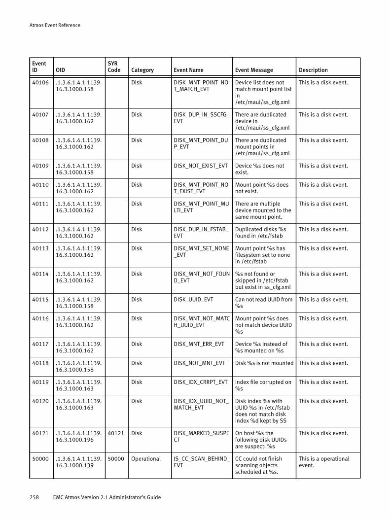
Atmos Event Reference
40106 .1.3.6.1.4.1.1139.16.3.1000.158
Disk DISK_MNT_POINT_NOT_MATCH_EVT
Device list does not match mount point list in /etc/maui/ss_cfg.xml
This is a disk event.
40107 .1.3.6.1.4.1.1139.16.3.1000.162
Disk DISK_DUP_IN_SSCFG_EVT
There are duplicated device in /etc/maui/ss_cfg.xml
This is a disk event.
40108 .1.3.6.1.4.1.1139.16.3.1000.162
Disk DISK_MNT_POINT_DUP_EVT
There are duplicated mount points in /etc/maui/ss_cfg.xml
This is a disk event.
40109 .1.3.6.1.4.1.1139.16.3.1000.158
Disk DISK_NOT_EXIST_EVT Device %s does not exist.
This is a disk event.
40110 .1.3.6.1.4.1.1139.16.3.1000.162
Disk DISK_MNT_POINT_NOT_EXIST_EVT
Mount point %s does not exist.
This is a disk event.
40111 .1.3.6.1.4.1.1139.16.3.1000.162
Disk DISK_MNT_POINT_MULTI_EVT
There are multiple device mounted to the same mount point.
This is a disk event.
40112 .1.3.6.1.4.1.1139.16.3.1000.162
Disk DISK_DUP_IN_FSTAB_EVT
Duplicated disks %s found in /etc/fstab
This is a disk event.
40113 .1.3.6.1.4.1.1139.16.3.1000.162
Disk DISK_MNT_SET_NONE_EVT
Mount point %s has filesystem set to none in /etc/fstab
This is a disk event.
40114 .1.3.6.1.4.1.1139.16.3.1000.162
Disk DISK_MNT_NOT_FOUND_EVT
%s not found or skipped in /etc/fstab but exist in ss_cfg.xml
This is a disk event.
40115 .1.3.6.1.4.1.1139.16.3.1000.158
Disk DISK_UUID_EVT Can not read UUID from %s
This is a disk event.
40116 .1.3.6.1.4.1.1139.16.3.1000.162
Disk DISK_MNT_NOT_MATCH_UUID_EVT
Mount point %s does not match device UUID %s
This is a disk event.
40117 .1.3.6.1.4.1.1139.16.3.1000.162
Disk DISK_MNT_ERR_EVT Device %s instead of %s mounted on %s
This is a disk event.
40118 .1.3.6.1.4.1.1139.16.3.1000.158
Disk DISK_NOT_MNT_EVT Disk %s is not mounted This is a disk event.
40119 .1.3.6.1.4.1.1139.16.3.1000.163
Disk DISK_IDX_CRRPT_EVT Index file corrupted on %s
This is a disk event.
40120 .1.3.6.1.4.1.1139.16.3.1000.163
Disk DISK_IDX_UUID_NOT_MATCH_EVT
Disk index %s with UUID %s in /etc/fstab does not match disk index %d kept by SS
This is a disk event.
40121 .1.3.6.1.4.1.1139.16.3.1000.196
40121 Disk DISK_MARKED_SUSPECT
On host %s the following disk UUIDs are suspect: %s
This is a disk event.
50000 .1.3.6.1.4.1.1139.16.3.1000.139
50000 Operational JS_CC_SCAN_BEHIND_EVT
CC could not finish scanning objects scheduled at %s.
This is a operational event.
Event ID OID
SYR Code Category Event Name Event Message Description
258 EMC Atmos Version 2.1 Administrator’s Guide
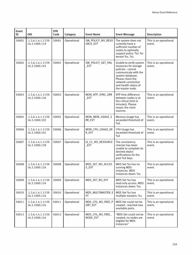
Atmos Event Reference
50001 .1.3.6.1.4.1.1139.16.3.1000.119
50001 Operational SM_POLICY_NO_RESOURCE_EVT
The system does not currently have a sufficient number of nodes to optimally support policy '%s' for tenant %s. %s
This is an operational event.
50002 .1.3.6.1.4.1.1139.16.3.1000.145
50002 Operational SM_POLICY_GET_FAIL_EVT
Unable to verify system resources for storage policies - cannot communicate with the system database. Please check the network connection and health status of the master node.
This is an operational event.
50003 .1.3.6.1.4.1.1139.16.3.1000.126
50003 Operational MON_NTP_SYNC_ERR_EVT
NTP time difference between nodes is at the critical limit (4 minutes). Please resync the clock sources.
This is an operational event.
50005 .1.3.6.1.4.1.1139.16.3.1000.102
50005 Operational MON_MEM_USAGE_ERR_EVT
Memory Usage has exceeded threshold of %d.
This is an operational event.
50006 .1.3.6.1.4.1.1139.16.3.1000.101
50006 Operational MON_CPU_USAGE_ERR_EVT
CPU Usage has exceeded threshold of %d
This is an operational event.
50007 .1.3.6.1.4.1.1139.16.3.1000.139
50007 Operational JS_CC_NO_RESOURCE_EVT
The consistency checker has been unable to complete its desired object verifications for the past %d days.
This is an operational event.
50008 .1.3.6.1.4.1.1139.16.3.1000.124
50008 Operational MDS_SET_NO_ACCESS_EVT
MDS Set %s has no running MDS instances. MDS instances down: %s
This is an operational event.
50009 .1.3.6.1.4.1.1139.16.3.1000.124
50009 Operational MDS_SET_RO_EVT MDS Set %s has read-only access. MDS instances down: %s.
This is an operational event.
50010 .1.3.6.1.4.1.1139.16.3.1000.124
50010 Operational MDS_MULTIMASTER_EVT
MDS Set %s has multiple masters: %s
This is an operational event.
50011 .1.3.6.1.4.1.1139.16.3.1000.124
50011 Operational MDS_CFG_NO_FREE_PORT_EVT
MDS Set could not be created - reached max available ports.
This is an operational event.
50012 .1.3.6.1.4.1.1139.16.3.1000.124
50012 Operational MDS_CFG_NO_FREE_NODE_EVT
"MDS Set could not be created, no nodes are eligible for MDS instances"
This is an operational event.
Event ID OID
SYR Code Category Event Name Event Message Description
259
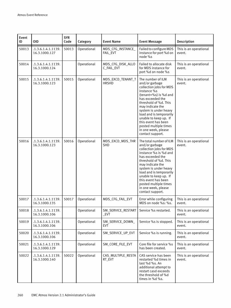
Atmos Event Reference
50013 .1.3.6.1.4.1.1139.16.3.1000.127
50013 Operational MDS_CFG_INSTANCE_FAIL_EVT
Failed to configure MDS instance for port %d on node %s
This is an operational event.
50014 .1.3.6.1.4.1.1139.16.3.1000.124
Operational MDS_CFG_DISK_ALLOC_FAIL_EVT
Failed to allocate disk for MDS instance for port %d on node %s
This is an operational event.
50015 .1.3.6.1.4.1.1139.16.3.1000.123
50015 Operational MDS_EXCD_TENANT_THRSHD
The number of ILM and/or garbage collection jobs for MDS instance %s (tenant=%s) is %d and has exceeded the threshold of %d. This may indicate the system is under heavy load and is temporarily unable to keep up. If this event has been posted multiple times in one week, please contact support.
This is an operational event.
50016 .1.3.6.1.4.1.1139.16.3.1000.123
50016 Operational MDS_EXCD_MDS_THRSHD
The total number of ILM and/or garbage collection jobs for MDS instance %s is %d and has exceeded the threshold of %d. This may indicate the system is under heavy load and is temporarily unable to keep up. If this event has been posted multiple times in one week, please contact support.
This is an operational event.
50017 .1.3.6.1.4.1.1139.16.3.1000.135
50017 Operational MDS_CFG_FAIL_EVT Error while configuring MDS on node %s: %s.
This is an operational event.
50018 .1.3.6.1.4.1.1139.16.3.1000.106
Operational SM_SERVICE_RESTART_EVT
Service %s restarted. This is an operational event.
50019 .1.3.6.1.4.1.1139.16.3.1000.106
Operational SM_SERVICE_DOWN_EVT
Service %s is stopped. This is an operational event.
50020 .1.3.6.1.4.1.1139.16.3.1000.106
Operational SM_SERVICE_UP_EVT Service %s is running. This is an operational event.
50021 .1.3.6.1.4.1.1139.16.3.1000.129
Operational SM_CORE_FILE_EVT Core file for service %s has been created.
This is an operational event.
50022 .1.3.6.1.4.1.1139.16.3.1000.140
50022 Operational CAS_MULTIPLE_RESTART_EVT
CAS service has been restarted %d times in last %d %s. An additional attempt to restart casd exceeds the threshold of %d times in %d %s.
This is an operational event.
Event ID OID
SYR Code Category Event Name Event Message Description
260 EMC Atmos Version 2.1 Administrator’s Guide

Atmos Event Reference
50023 .1.3.6.1.4.1.1139.16.3.1000.141
50023 Operational CAS_LRG_BLOB_UNORPHAN_QUEUE_EVT
CAS blob unorphaning queue size (%d) exceeds the threshold (%d).
This is an operational event.
50024 .1.3.6.1.4.1.1139.16.3.1000.141
50024 Operational CAS_LRG_BLOB_DELETE_QUEUE_EVT
CAS blob delete queue size (%d) exceeds the threshold (%d).
This is an operational event.
50025 .1.3.6.1.4.1.1139.16.3.1000.141
50025 Operational CAS_LRG_MD_PROMO_QUEUE_EVT
CAS metadata promotion queue size (%d) exceeds the threshold (%d).
This is an operational event.
50026 .1.3.6.1.4.1.1139.16.3.1000.151
50026 Operational WS_HTTPD_WORKER_CRASH
An httpd worker has crashed %d times in the last %d %s. This exceeds the threshold of %d times in %d %s.
Apache httpd worker crash threshold reached.
50027 .1.3.6.1.4.1.1139.16.3.1000.145
50027 Operational SM_DB_COMMUNICATION_ISSUE
Cannot communicate with RMG Database. Please check the network connection and the health of the master node.
This is a generic event for DB communications
50028 .1.3.6.1.4.1.1139.16.3.1000.145
Operational SM_DB_COMMUNICATION_RESTORED
Communication with the RMG Database has been restored.
This is a generic event for DB communications
50029 .1.3.6.1.4.1.1139.16.3.1000.148
Operational MGMT_DB_FAILOVER_START
Failover of management db master from %s to %s has begun.
This is an operational event.
50030 .1.3.6.1.4.1.1139.16.3.1000.148
Operational MGMT_DB_FAILOVER_SUCCESSFUL
Failover of management db master to %s was successful.
This is an operational event.
50031 .1.3.6.1.4.1.1139.16.3.1000.148
Operational MGMT_DB_FAILOVER_FAILED
Failover of management db master to %s has encountered an error.
This is an operational event.
50032 .1.3.6.1.4.1.1139.16.3.1000.194
Operational SYNC_UID_FAILED Lockbox operation error - %s.
This is an operational event.
50033 .1.3.6.1.4.1.1139.16.3.1000.210
Operational COMMAND_TIMEOUT Command timed out. Could not determine the state of '%s'. Details: %s.
Failed check due to command timeout.
51000 Operational MON_ENGINE_ENTITY_CHANGE_EVT
Entity (%s) is %s. Monitor engine entity change event.
51007 .1.3.6.1.4.1.1139.16.3.1000.198
Operational MON_ENGINE_FAN_SPEED_EVT
Value of metric '%s' is '%s'. New status is '%s'. Previous status was '%s'. Details: %s.
This metric reads the fan speed information of a specific fan on the platform.
Event ID OID
SYR Code Category Event Name Event Message Description
261

Atmos Event Reference
51008 .1.3.6.1.4.1.1139.16.3.1000.199
51008 Operational MON_ENGINE_FAN_REDUNDANCY_EVT
Value of metric '%s' is '%s'. New status is '%s'. Previous status was '%s'. Details: %s.
This metric is the metric of the status of fan redundancy on the platform.
51009 .1.3.6.1.4.1.1139.16.3.1000.200
51009 Operational MON_ENGINE_FAN_STATUS_EVT
Value of metric '%s' is '%s'. New status is '%s'. Previous status was '%s'. Details: %s.
This metric is the metric of the status of a fan in the server.
51010 .1.3.6.1.4.1.1139.16.3.1000.201
51010 Operational MON_ENGINE_BATTERY_STATUS_EVT
Value of metric '%s' is '%s'. New status is '%s'. Previous status was '%s'. Details: %s.
This metric reads the server battery status.
51011 Operational MON_ENGINE_INTRUSION_EVT
Value of metric '%s' is '%s'. New status is '%s'. Previous status was '%s'. Details: %s.
This metric monitor the chassis security status.
51012 .1.3.6.1.4.1.1139.16.3.1000.193
Operational MON_ENGINE_NETWORK_INTERFACE_STATUS_EVT
Value of metric '%s' is '%s'. New status is '%s'. Previous status was '%s'. Details: %s.
This metrics monitors the network interface status.
51013 .1.3.6.1.4.1.1139.16.3.1000.202
51013 Operational MON_ENGINE_POWER_SUPPLY_REDUNDANCY_EVT
Value of metric '%s' is '%s'. New status is '%s'. Previous status was '%s'. Details: %s.
This metric is the metric of the status of power redundancy on the platform.
51014 .1.3.6.1.4.1.1139.16.3.1000.203
51014 Operational MON_ENGINE_POWER_SUPPLY_METRIC_EVT
Value of metric '%s' is '%s'. New status is '%s'. Previous status was '%s'. Details: %s.
This metric is the metric of the specific power supply.
51015 .1.3.6.1.4.1.1139.16.3.1000.204
51015 Operational MON_ENGINE_RAID_CONTROLLER_STATE_EVT
Value of metric '%s' is '%s'. New status is '%s'. Previous status was '%s'. Details: %s.
This metric reads the status of a specific raid controller.
51016 .1.3.6.1.4.1.1139.16.3.1000.205
51016 Operational MON_ENGINE_ENCLOSURE_STATE_EVT
Value of metric '%s' is '%s'. New status is '%s'. Previous status was '%s'. Details: %s.
This metric reads the enclosure state.
51017 .1.3.6.1.4.1.1139.16.3.1000.206
51017 Operational MON_ENGINE_CHANNEL_STATE_EVT
Value of metric '%s' is '%s'. New status is '%s'. Previous status was '%s'. Details: %s.
This metric reads the physical disk state.
51018 .1.3.6.1.4.1.1139.16.3.1000.207
51018 Operational MON_ENGINE_VIRTUAL_DISK_STATE_EVT
Value of metric '%s' is '%s'. New status is '%s'. Previous status was '%s'. Details: %s.
This metric reads the virtual disk state.
51019 .1.3.6.1.4.1.1139.16.3.1000.208
51019 Operational MON_ENGINE_INTERNAL_DISK_ARRAY_STATUS_EVT
Value of metric '%s' is '%s'. New status is '%s'. Previous status was '%s'. Details: %s.
This metric reads the internal disk array status.
Event ID OID
SYR Code Category Event Name Event Message Description
262 EMC Atmos Version 2.1 Administrator’s Guide

Atmos Event Reference
51020 .1.3.6.1.4.1.1139.16.3.1000.101
Operational MON_ENGINE_CPU_UTILIZATION_EVT
Value of metric '%s' is '%s'. New status is '%s'. Previous status was '%s'. Details: %s.
This metric reads the system CPU utilization information of the OS.
51021 .1.3.6.1.4.1.1139.16.3.1000.102
51021 Operational MON_ENGINE_TOTAL_MEMORY_UTILIZATION_EVT
Value of metric '%s' is '%s'. New status is '%s'. Previous status was '%s'. Details: %s.
This metric monitors the utilization of system memory including both physical memory and swap memory
51022 .1.3.6.1.4.1.1139.16.3.1000.102
Operational MON_ENGINE_PHYSICAL_MEMORY_UTILIZATION_EVT
Value of metric '%s' is '%s'. New status is '%s'. Previous status was '%s'. Details: %s.
This metric monitors the utilization of Physical memory
51023 .1.3.6.1.4.1.1139.16.3.1000.103
Operational MON_ENGINE_SWAP_MEMORY_UTILIZATION_EVT
Value of metric '%s' is '%s'. New status is '%s'. Previous status was '%s'. Details: %s.
This metric monitors the utilization of Swap memory
51024 .1.3.6.1.4.1.1139.16.3.1000.104
51024 Operational MON_ENGINE_FILE_SYSTEM_CAPACITY
Value of metric '%s' is '%s'. New status is '%s'. Previous status was '%s'. Details: %s.
This metric monitors the space utilization of a specified mount point
51025 .1.3.6.1.4.1.1139.16.3.1000.106
51025 Operational MON_ENGINE_SERVICE_STATUS_EVT
Value of metric '%s' is '%s'. New status is '%s'. Previous status was '%s'. Details: %s.
The status of a service
51026 .1.3.6.1.4.1.1139.16.3.1000.105
51026 Operational MON_ENGINE_SERVICE_MEMORY_USAGE_EVT
Value of metric '%s' is '%s'. New status is '%s'. Previous status was '%s'. Details: %s.
The memory usage of a service
51027 .1.3.6.1.4.1.1139.16.3.1000.209
51027 Operational MON_ENGINE_TEMPERATURE_SENSOR_METRIC_EVT
Value of metric '%s' is '%s'. New status is '%s'. Previous status was '%s'. Details: %s.
"Temperature Sensor Metric is the metric of a specific temperature sensor, it reads the value of the temperature information."
51028 Operational MON_ENGINE_VIRTUAL_MACHINE_CPU_EFFECTIVE_SPEED_EVT
Value of metric '%s' is '%s'. New status is '%s'. Previous status was '%s'. Details: %s.
This metric monitors the CPU effective speed for the virtual machine
51029 .1.3.6.1.4.1.1139.16.3.1000.147
Configuration SM_PG_DB_CONNECTION_MONITOR
Value of metric '%s' is '%s'. New status is '%s'. Previous status was '%s'. Details: %s.
This metric monitors the number of connections to the PostGRES database
51030 .1.3.6.1.4.1.1139.16.3.1000.111
51030 Configuration MON_RMG_STATUS %s %s has been %s This monitors the RMG status of an Atmos System
51031 .1.3.6.1.4.1.1139.16.3.1000.110
51031 Configuration MON_IS_STATUS %s %s has been %s This monitors the Segment status of an Atmos System
Event ID OID
SYR Code Category Event Name Event Message Description
263
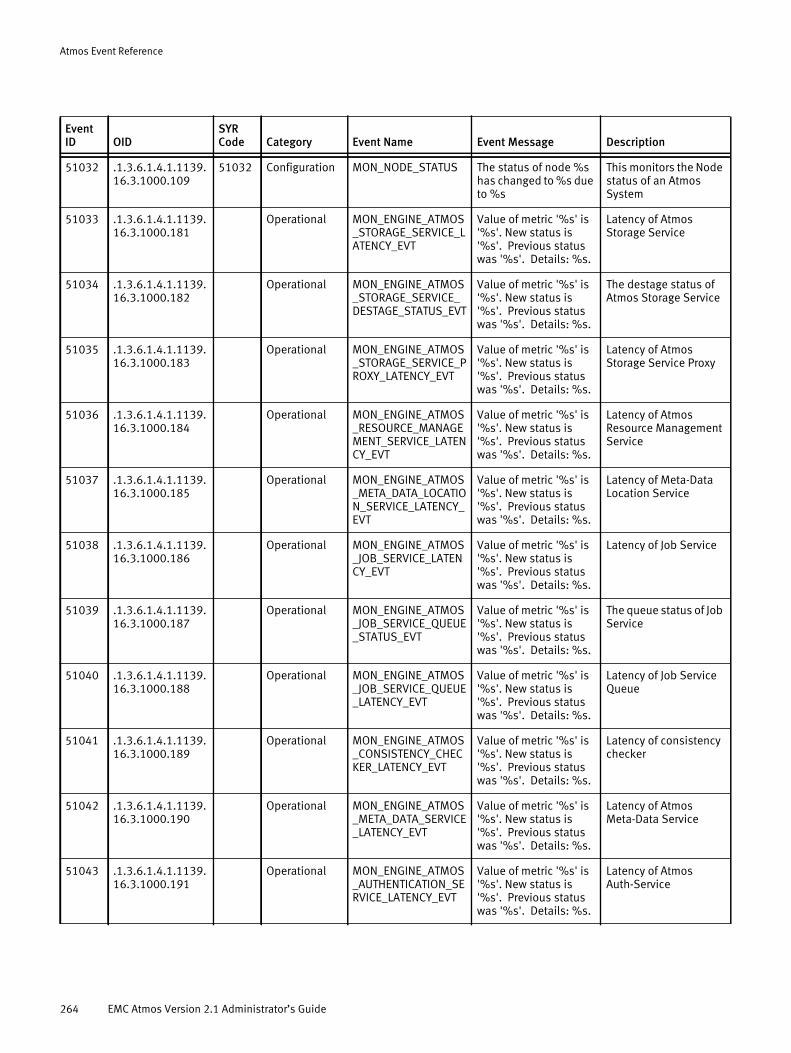
Atmos Event Reference
51032 .1.3.6.1.4.1.1139.16.3.1000.109
51032 Configuration MON_NODE_STATUS The status of node %s has changed to %s due to %s
This monitors the Node status of an Atmos System
51033 .1.3.6.1.4.1.1139.16.3.1000.181
Operational MON_ENGINE_ATMOS_STORAGE_SERVICE_LATENCY_EVT
Value of metric '%s' is '%s'. New status is '%s'. Previous status was '%s'. Details: %s.
Latency of Atmos Storage Service
51034 .1.3.6.1.4.1.1139.16.3.1000.182
Operational MON_ENGINE_ATMOS_STORAGE_SERVICE_DESTAGE_STATUS_EVT
Value of metric '%s' is '%s'. New status is '%s'. Previous status was '%s'. Details: %s.
The destage status of Atmos Storage Service
51035 .1.3.6.1.4.1.1139.16.3.1000.183
Operational MON_ENGINE_ATMOS_STORAGE_SERVICE_PROXY_LATENCY_EVT
Value of metric '%s' is '%s'. New status is '%s'. Previous status was '%s'. Details: %s.
Latency of Atmos Storage Service Proxy
51036 .1.3.6.1.4.1.1139.16.3.1000.184
Operational MON_ENGINE_ATMOS_RESOURCE_MANAGEMENT_SERVICE_LATENCY_EVT
Value of metric '%s' is '%s'. New status is '%s'. Previous status was '%s'. Details: %s.
Latency of Atmos Resource Management Service
51037 .1.3.6.1.4.1.1139.16.3.1000.185
Operational MON_ENGINE_ATMOS_META_DATA_LOCATION_SERVICE_LATENCY_EVT
Value of metric '%s' is '%s'. New status is '%s'. Previous status was '%s'. Details: %s.
Latency of Meta-Data Location Service
51038 .1.3.6.1.4.1.1139.16.3.1000.186
Operational MON_ENGINE_ATMOS_JOB_SERVICE_LATENCY_EVT
Value of metric '%s' is '%s'. New status is '%s'. Previous status was '%s'. Details: %s.
Latency of Job Service
51039 .1.3.6.1.4.1.1139.16.3.1000.187
Operational MON_ENGINE_ATMOS_JOB_SERVICE_QUEUE_STATUS_EVT
Value of metric '%s' is '%s'. New status is '%s'. Previous status was '%s'. Details: %s.
The queue status of Job Service
51040 .1.3.6.1.4.1.1139.16.3.1000.188
Operational MON_ENGINE_ATMOS_JOB_SERVICE_QUEUE_LATENCY_EVT
Value of metric '%s' is '%s'. New status is '%s'. Previous status was '%s'. Details: %s.
Latency of Job Service Queue
51041 .1.3.6.1.4.1.1139.16.3.1000.189
Operational MON_ENGINE_ATMOS_CONSISTENCY_CHECKER_LATENCY_EVT
Value of metric '%s' is '%s'. New status is '%s'. Previous status was '%s'. Details: %s.
Latency of consistency checker
51042 .1.3.6.1.4.1.1139.16.3.1000.190
Operational MON_ENGINE_ATMOS_META_DATA_SERVICE_LATENCY_EVT
Value of metric '%s' is '%s'. New status is '%s'. Previous status was '%s'. Details: %s.
Latency of Atmos Meta-Data Service
51043 .1.3.6.1.4.1.1139.16.3.1000.191
Operational MON_ENGINE_ATMOS_AUTHENTICATION_SERVICE_LATENCY_EVT
Value of metric '%s' is '%s'. New status is '%s'. Previous status was '%s'. Details: %s.
Latency of Atmos Auth-Service
Event ID OID
SYR Code Category Event Name Event Message Description
264 EMC Atmos Version 2.1 Administrator’s Guide

Atmos Event Reference
51044 .1.3.6.1.4.1.1139.16.3.1000.164
51044 Operational MON_ENGINE_NUM_CORES_EVT
Value of metric '%s' is '%s'. New status is '%s'. Previous status was '%s'. Details: %s.
This metric monitors the number of core dumps
51045 .1.3.6.1.4.1.1139.16.3.1000.112
Operational MON_ENGINE_POLICY_SYNC_FAILED
The system weas unable to successfully distributed policy information to all nodes. To resubmit the request press 'retry' from the Tenant Summary page of the tenant administration GUI.
This metric monitors the policy creation
51046 .1.3.6.1.4.1.1139.16.3.1000.109
Configuration MON_NODE_COMMUNICATION_STATUS_RESTORED
Communication with node %s has been restored
This reports when the communication of a Node is restored
51047 .1.3.6.1.4.1.1139.16.3.1000.111
51047 Configuration MON_RMG_COMMUNICATION_STATUS_LOST
Communication with RMG %s was lost
This reports when the communication of an RMG is lost
51048 .1.3.6.1.4.1.1139.16.3.1000.111
Configuration MON_RMG_COMMUNICATION_STATUS_RESTORED
Communication with RMG %s has been restored
This reports when the communication of an RMG is restored
51049 .1.3.6.1.4.1.1139.16.3.1000.110
51049 Configuration MON_IS_COMMUNICATION_STATUS_LOST
Communication with installation segment %s has been lost
This reports when the communication of an IS is lost
51050 .1.3.6.1.4.1.1139.16.3.1000.110
Configuration MON_IS_COMMUNICATION_STATUS_RESTORED
Communication with installation segment %s has been restored
This reports when the communication of an IS is restored
51051 .1.3.6.1.4.1.1139.16.3.1000.109
51051 Configuration MON_NODE_CONNECTION_STATUS_LOST
Connection with node %s was lost
This reports when the connection of a Node is lost
51052 .1.3.6.1.4.1.1139.16.3.1000.109
51052 Configuration MON_NODE_COMMUNICATION_STATUS_LOST
Communication with node %s has been lost
This reports when the communication of a Node is lost
51053 .1.3.6.1.4.1.1139.16.3.1000.110
51053 Configuration MON_IS_CONNECTION_STATUS_LOST
Connection with installation segment %s was lost
This reports when the connection with an IS is lost
51054 .1.3.6.1.4.1.1139.16.3.1000.106
51054 Operational MON_ENGINE_CRIT_SERVICE_STATUS_EVT
Value of metric '%s' is '%s'. New status is '%s'. Previous status was '%s'. Details: %s.
The status of a Critical service
51055 .1.3.6.1.4.1.1139.16.3.1000.106
Operational MON_ENGINE_SERVICE_DOWN_EVT
Value of metric '%s' is '%s'. New status is '%s'. Previous status was '%s'. Details: %s.
Down status of a service
Event ID OID
SYR Code Category Event Name Event Message Description
265

Atmos Event Reference
51056 .1.3.6.1.4.1.1139.16.3.1000.174
51056 Operational MDS_DB_WOULD_ROLLBACK
An MDS transaction conflict has been detected. MDS instance %s has been shutdown.
BDB detected transaction conflict
51057 .1.3.6.1.4.1.1139.16.3.1000.175
51057 Operational MDS_REP_PANIC A BDB database panic has been detected for MDS instance %s
BDB DB panic detected
51058 .1.3.6.1.4.1.1139.16.3.1000.176
51058 Operational MDS_SAVE_ROLLBACK
MDS created a back up of its automatically rolled back transaction log.
51059 .1.3.6.1.4.1.1139.16.3.1000.177
Operational MDS_MASTER_TO_SLAVE
MDS %s has transitioned from master to slave state.
51060 .1.3.6.1.4.1.1139.16.3.1000.178
Operational MDS_DB_REP_LEASE_EXPIRED
Master lease for MDS %s has expired.
MDS master lease expired
51061 .1.3.6.1.4.1.1139.16.3.1000.122
Operational HA_VIP_STATUS HA Virtual IP %s has been %s on node %s
HA VIP status
51062 .1.3.6.1.4.1.1139.16.3.1000.149
51062 Operational MON_ENGINE_META_DATA_SERVICE_CAPACITY
Value of metric '%s' is '%s'. New status is '%s'. Previous status was '%s'. Details: %s.
This metric monitors the disk utilization of a specified Metadata Service instance
51063 .1.3.6.1.4.1.1139.16.3.1000.160
51063 Operational MON_ENGINE_STORAGE_SERVICE_CAPACITY
Value of metric '%s' is '%s'. New status is '%s'. Previous status was '%s'. Details: %s.
This metric monitors the disk utilization of the Storage Service on this node
59999 .1.3.6.1.4.1.1139.16.3.1000.1000
Operational UI_OPERATIONAL_TEST_EVT
This is a notification test event.
GUI test event.
Event ID OID
SYR Code Category Event Name Event Message Description
266 EMC Atmos Version 2.1 Administrator’s Guide
APPENDIX BAtmos MIB
This appendix provides descriptions and other information specific to the Atmos MIB, and includes the following sections:
◆ Atmos MIB Version Group ..................................................................................... 268◆ Atmos Software Version Group.............................................................................. 268◆ Atmos Capacity Group........................................................................................... 268◆ Atmos Service Status Group.................................................................................. 271◆ Atmos Metadata Service Group ............................................................................. 272◆ Atmos Storage Service Group................................................................................ 272◆ Atmos Job Service Group....................................................................................... 272◆ Atmos Web Service Group..................................................................................... 275◆ Atmos Notification Group...................................................................................... 275◆ Atmos Group Conformance Information................................................................. 288◆ Atmos Compliance Information ............................................................................. 289
Atmos MIB 267
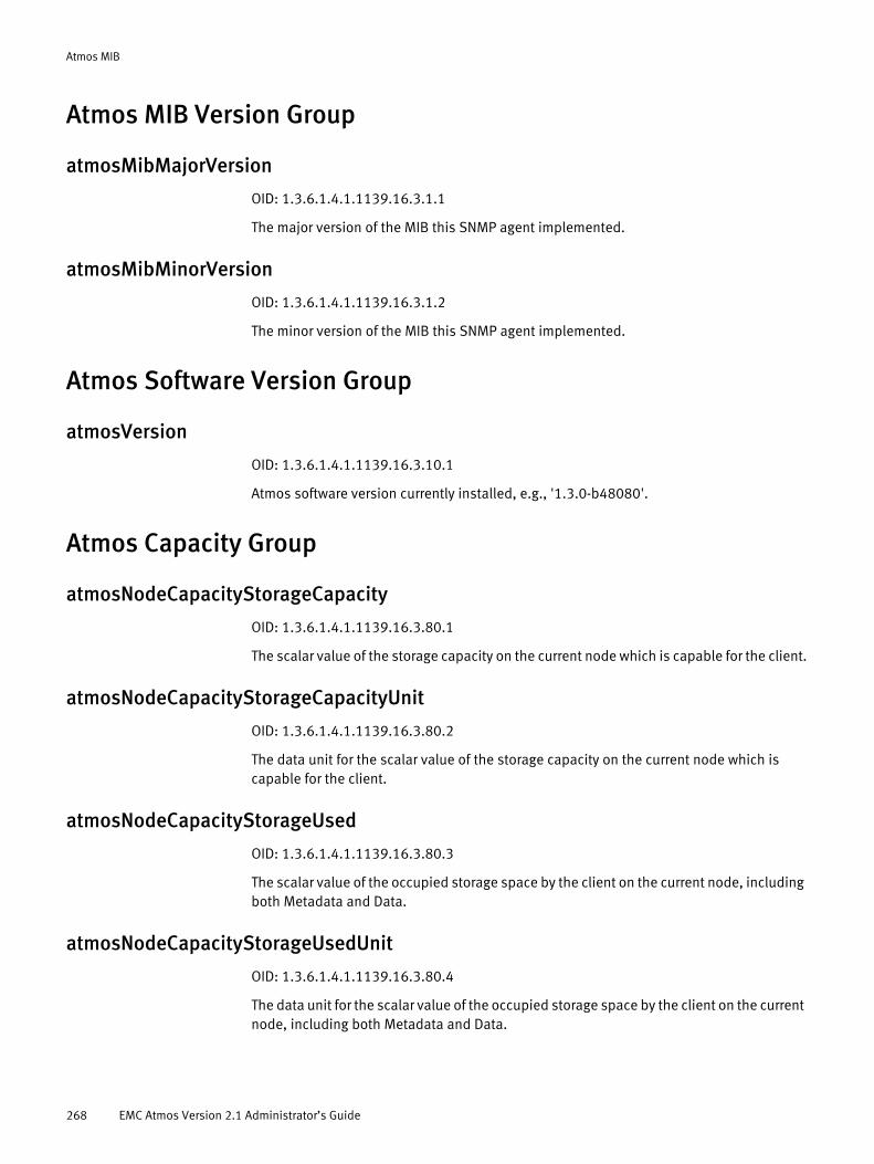
Atmos MIB
Atmos MIB Version Group
atmosMibMajorVersion
OID: 1.3.6.1.4.1.1139.16.3.1.1
The major version of the MIB this SNMP agent implemented.
atmosMibMinorVersion
OID: 1.3.6.1.4.1.1139.16.3.1.2
The minor version of the MIB this SNMP agent implemented.
Atmos Software Version Group
atmosVersion
OID: 1.3.6.1.4.1.1139.16.3.10.1
Atmos software version currently installed, e.g., '1.3.0-b48080'.
Atmos Capacity Group
atmosNodeCapacityStorageCapacity
OID: 1.3.6.1.4.1.1139.16.3.80.1
The scalar value of the storage capacity on the current node which is capable for the client.
atmosNodeCapacityStorageCapacityUnit
OID: 1.3.6.1.4.1.1139.16.3.80.2
The data unit for the scalar value of the storage capacity on the current node which is capable for the client.
atmosNodeCapacityStorageUsed
OID: 1.3.6.1.4.1.1139.16.3.80.3
The scalar value of the occupied storage space by the client on the current node, including both Metadata and Data.
atmosNodeCapacityStorageUsedUnit
OID: 1.3.6.1.4.1.1139.16.3.80.4
The data unit for the scalar value of the occupied storage space by the client on the current node, including both Metadata and Data.
268 EMC Atmos Version 2.1 Administrator’s Guide
Atmos MIB
atmosNodeCapacityStorageAvailable
OID: 1.3.6.1.4.1.1139.16.3.80.5
The scalar value of the available storage space on the current node for the client.
atmosNodeCapacityStorageAvailableUnit
OID: 1.3.6.1.4.1.1139.16.3.80.6
The data unit for the scalar value of the available storage space on the current node for the client.
atmosNodeCapacityStoragePercentUsed
OID: 1.3.6.1.4.1.1139.16.3.80.7
The occupied storage space by the client in percentage on the current node, including both Metadata and Data.
atmosNodeCapacityMetadataCapacity
OID: 1.3.6.1.4.1.1139.16.3.80.8
The scalar value of the storage capacity for Metadata on the current node.
atmosNodeCapacityMetadataCapacityUnit
OID: 1.3.6.1.4.1.1139.16.3.80.9
The data unit for the scalar value of the storage capacity for Metadata on the current node.
atmosNodeCapacityMetadataUsed
OID: 1.3.6.1.4.1.1139.16.3.80.10
The scalar value of the occupied storage space by Metadata on the current node.
atmosNodeCapacityMetadataUsedUnit
OID: 1.3.6.1.4.1.1139.16.3.80.11
The data unit for the scalar value of the occupied storage space by Metadata on the current node.
atmosNodeCapacityMetadataAvailable
OID: 1.3.6.1.4.1.1139.16.3.80.12
The scalar value of the available storage space for Metadata on the current node.
atmosNodeCapacityMetadataAvailableUnit
OID: 1.3.6.1.4.1.1139.16.3.80.13
Atmos Capacity Group 269

Atmos MIB
The data unit for the scalar value of the available storage space for Metadata on the current node.
atmosNodeCapacityMetadataPercentUsed
OID: 1.3.6.1.4.1.1139.16.3.80.14
The occupied storage space by Metadata in percentage on the current node.
atmosNodeCapacityDataCapacity
OID: 1.3.6.1.4.1.1139.16.3.80.15
The scalar value of the storage capacity for Data on current node.
atmosNodeCapacityDataCapacityUnit
OID: 1.3.6.1.4.1.1139.16.3.80.16
The data unit for the scalar value of the storage capacity for Data on current node.
atmosNodeCapacityDataUsed
OID: 1.3.6.1.4.1.1139.16.3.80.17
The scalar value of the occupied storage space by Data on the current node.
atmosNodeCapacityDataUsedUnit
OID: 1.3.6.1.4.1.1139.16.3.80.18
The data unit for the scalar value of the occupied storage space by Data on the current node.
atmosNodeCapacityDataAvailable
OID: 1.3.6.1.4.1.1139.16.3.80.19
The scalar value of the available storage space for Data on the current node.
atmosNodeCapacityDataAvailableUnit
OID: 1.3.6.1.4.1.1139.16.3.80.20
The data unit for the scalar value of the available storage space for Data on current node.
atmosNodeCapacityDataPercentUsed
OID: 1.3.6.1.4.1.1139.16.3.80.21
The occupied storage space by Data in percentage on the current node.
270 EMC Atmos Version 2.1 Administrator’s Guide
Atmos MIB
Atmos Service Status Group
atmosServiceActiveEntries
OID: 1.3.6.1.4.1.1139.16.3.90.1
The number of available Atmos services in the system.
atmosServiceTable
OID: 1.3.6.1.4.1.1139.16.3.90.2
A table defining each Atmos service's detail status entry.
atmosServiceEntryOID: 1.3.6.1.4.1.1139.16.3.90.2.1
An entry describing a given Atmos service's detail status information.
atmosServiceIndex
OID: 1.3.6.1.4.1.1139.16.3.90.2.1.1
The index for a given Service status instance.
atmosServiceName
OID: 1.3.6.1.4.1.1139.16.3.90.2.1.2
The name of the Atmos service.
atmosServiceStatus
OID: 1.3.6.1.4.1.1139.16.3.90.2.1.3
The current status of the Atmos service.
atmosServiceLatency
OID: 1.3.6.1.4.1.1139.16.3.90.2.1.4
The latency of the Atmos service in microseconds.
atmosServiceOid
OID: 1.3.6.1.4.1.1139.16.3.90.2.1.5
The corresponding OID of the Atmos service, which can be queried to get more details about the service. If not applicable, should set as .0.
atmosServiceMemoryUsed
OID: 1.3.6.1.4.1.1139.16.3.90.2.1.6
The memory used by the Atmos service.
atmosServiceMemoryUsedUnit
OID: 1.3.6.1.4.1.1139.16.3.90.2.1.7
Atmos Service Status Group 271
Atmos MIB
The data unit for the memory used by the Atmos service.
Atmos Metadata Service Group
atmosMDSUpmasterCount
OID: 1.3.6.1.4.1.1139.16.3.100.1
The number of masters for replication.
atmosMDSContainerCount
OID: 1.3.6.1.4.1.1139.16.3.100.2
The number of containers.
atmosMDSReplicaGroupCount
OID: 1.3.6.1.4.1.1139.16.3.100.3
The number of replication groups.
Atmos Storage Service GroupAtmos storage service destage status.
atmosSSDestageStatus
OID: 1.3.6.1.4.1.1139.16.3.110.1
Currently destage status of the Atmos Storage Service.
Atmos Job Service GroupAtmos Job queue status type.
atmosJSQueueStatus (obsolete)
OID: 1.3.6.1.4.1.1139.16.3.120.1
Current status of the Job Service queue.
atmosJSQueueLength
OID: 1.3.6.1.4.1.1139.16.3.120.2
The length of the Job Service queue.
atmosJSRecoverQueueLength
OID: 1.3.6.1.4.1.1139.16.3.120.3
The number of jobs on the Job Service recover queue.
272 EMC Atmos Version 2.1 Administrator’s Guide
Atmos MIB
atmosJSRecoverDequeueRate
OID: 1.3.6.1.4.1.1139.16.3.120.5
The rate of jobs being dequeued from the Job Service recover queue, in jobs per second.
atmosJSRecoverByteRate
OID: 1.3.6.1.4.1.1139.16.3.120.6
The rate of Job Service recovery data transferred.
atmosJSReclaimQueueLength
OID: 1.3.6.1.4.1.1139.16.3.120.7
The number of jobs on the Job Service reclaim queue.
atmosJSReclaimDequeueRate
OID: 1.3.6.1.4.1.1139.16.3.120.9
The rate of jobs being dequeued from the Job Service reclaim queue, in jobs per second.
atmosJSReclaimByteRate
OID: 1.3.6.1.4.1.1139.16.3.120.10
The rate of Job Service reclamation data transferred.
atmosJSReplicateQueueLength
OID: 1.3.6.1.4.1.1139.16.3.120.11
The number of jobs on the Job Service replicate queue.
atmosJSReplicateDequeueRate
OID: 1.3.6.1.4.1.1139.16.3.120.13
The rate of jobs being dequeued from the Job Service replicate queue, in jobs per second.
atmosJSReplicateByteRate
OID: 1.3.6.1.4.1.1139.16.3.120.14
The rate of Job Service replication data transferred.
atmosJSVerifyQueueLength
OID: 1.3.6.1.4.1.1139.16.3.120.18
The number of jobs on the Job Service verify queue.
Atmos Job Service Group 273

Atmos MIB
atmosJSVerifyDequeueRate
OID: 1.3.6.1.4.1.1139.16.3.120.20
The rate of jobs being dequeued from the Job Service verify queue, in jobs per second.
atmosJSVerifyByteRate
OID: 1.3.6.1.4.1.1139.16.3.120.21
The rate of Job Service verification data transferred.
atmosJSDatamigrationStatus
OID: 1.3.6.1.4.1.1139.16.3.120.22
Current status of the Job Service data migration queue.
atmosJSReclaimStatus
OID: 1.3.6.1.4.1.1139.16.3.120.23
Current status of the Job Service reclaim queue
atmosJSRecoverStatus
OID: 1.3.6.1.4.1.1139.16.3.120.24
Current status of the Job Service recover queue.
atmosJSReplicateStatus
OID: 1.3.6.1.4.1.1139.16.3.120.25
Current status of the Job Service replicate queue.
atmosJSRescanStatus
OID: 1.3.6.1.4.1.1139.16.3.120.26
Current status of the Job Service rescan queue.
atmosJSUpgradeStatus
OID: 1.3.6.1.4.1.1139.16.3.120.27
Current status of the Job Service upgrade queue.
atmosJSVerifyStatus
OID: 1.3.6.1.4.1.1139.16.3.120.28
Current status of the Job Service verify queue.
274 EMC Atmos Version 2.1 Administrator’s Guide
Atmos MIB
atmosJSDatamigrationQueueLength
OID: 1.3.6.1.4.1.1139.16.3.120.29
The number of jobs on the Job Service data migration queue.
atmosJSUpdateQueueLength
OID: 1.3.6.1.4.1.1139.16.3.120.31
The number of jobs on the Job Service update queue.
atmosJSRescanQueueLength
OID: 1.3.6.1.4.1.1139.16.3.120.31
The number of jobs on the Job Service Rescan queue.
Atmos Web Service Group
atmosWSReadsPerSec
OID: 1.3.6.1.4.1.1139.16.3.140.1
The number of reads per second from the web service interface for the current node.
atmosWSWritesPerSec
OID: 1.3.6.1.4.1.1139.16.3.140.2
The number of writes per second from the web service interface for the current node.
atmosWSDeletesPerSec
OID: 1.3.6.1.4.1.1139.16.3.140.3
The number of deletes per second from the web service interface for the current node.
atmosWSTransPerSec
OID: 1.3.6.1.4.1.1139.16.3.140.4
The number of transactions per second from the web service interface for the current node.
Atmos Notification Group
atmosNotificationVariables
OID: 1.3.6.1.4.1.1139.16.3.1000.1
atmosNotificationNodeOID: 1.3.6.1.4.1.1139.16.3.1000.1.1
Atmos Web Service Group 275

Atmos MIB
The name of the Atmos node that generated the notification.
atmosNotificationNodeUUIDOID: 1.3.6.1.4.1.1139.16.3.1000.1.2
The UUID of the Atmos node that generated the notification.
atmosNotificationOIDOID: 1.3.6.1.4.1.1139.16.3.1000.1.3
The OID that was used to identity the object which caused this notification. If not applicable, should set as .0.
atmosNotificationCurrentStatusOID: 1.3.6.1.4.1.1139.16.3.1000.1.4
The current status of the object which caused this notification.
atmosNotificationPreviousStatusOID: 1.3.6.1.4.1.1139.16.3.1000.1.5
The previous status of the object which caused this notification.
atmosNotificationMessageOID: 1.3.6.1.4.1.1139.16.3.1000.1.6
Detail message for this notification.
atmosNotificationCpuUsage
OID: 1.3.6.1.4.1.1139.16.3.1000.101
This notification is used to report the CPU usage status change on the system.
atmosNotificationMemoryUsage
OID: 1.3.6.1.4.1.1139.16.3.1000.102
This notification is used to report the physical memory usage status change on the system.
atmosNotificationSwapUsage
OID: 1.3.6.1.4.1.1139.16.3.1000.103
This notification is used to report the swap usage status change on the system.
atmosNotificationFilesystemUsage
OID: 1.3.6.1.4.1.1139.16.3.1000.104
This notification is used to report the file system disk space usage status change.
276 EMC Atmos Version 2.1 Administrator’s Guide
Atmos MIB
atmosNotificationServiceMemoryUsage
OID: 1.3.6.1.4.1.1139.16.3.1000.105
This notification is used to report the Atmos service memory usage status change on the system.
atmosNotificationServiceStatus
OID: 1.3.6.1.4.1.1139.16.3.1000.106
This notification is used to report the Atmos service status change.
atmosNotificationInternalCarrierStatus (obsolete)
OID: 1.3.6.1.4.1.1139.16.3.1000.107
This notification is used to report the internal carrier status change, e.g., eth0 is disconnected.
atmosNotificationExternalCarrierStatus (obsolete)
OID: 1.3.6.1.4.1.1139.16.3.1000.108
This notification is used to report the external carrier status change, e.g., eth1 is disconnected.
atmosNotificationNodeStatus
OID: 1.3.6.1.4.1.1139.16.3.1000.109
This notification is used to report the Atmos node status change.
atmosNotificationSegmentStatus
OID: 1.3.6.1.4.1.1139.16.3.1000.110
This notification is used to report the Atmos segment status change.
atmosNotificationRMGStatus
OID: 1.3.6.1.4.1.1139.16.3.1000.111
This notification is used to report the Atmos RMG status change.
atmosNotificationPolicySyncFailed
OID: 1.3.6.1.4.1.1139.16.3.1000.112
This notification is used to report the policy distribution failure.
atmosNotificationUidSyncFailed
OID: 1.3.6.1.4.1.1139.16.3.1000.113
This notification is used to report the UID distribution failure.
Atmos Notification Group 277

Atmos MIB
atmosNotificationDAEStatus (obsolete)
OID: 1.3.6.1.4.1.1139.16.3.1000.114
This notification is used to report the DAE status change of the system.
atmosNotificationDAEBackplaneStatus (obsolete)
OID: 1.3.6.1.4.1.1139.16.3.1000.115
This notification is used to report the DAE backplane status change of the system.
atmosNotificationDAEFanStatus (obsolete)
OID: 1.3.6.1.4.1.1139.16.3.1000.116
This notification is used to report the DAE fan status change of the system.
atmosNotificationDAETempStatus (obsolete)
OID: 1.3.6.1.4.1.1139.16.3.1000.117
This notification is used to report the DAE temperature status change of the system.
atmosNotificationDiskStatus (obsolete)
OID: 1.3.6.1.4.1.1139.16.3.1000.118
This notification is used to report the disk status change of the system.
atmosNotificationPolicyResourceStatus
OID: 1.3.6.1.4.1.1139.16.3.1000.119
This notification is used to report the policy resource status of the system.
atmosNotificationMgmtDBStatus (obsolete)
OID: 1.3.6.1.4.1.1139.16.3.1000.120
This notification is used to report the policy resource failure of the system.
atmosNotificationDiskRecovery (obsolete)
OID: 1.3.6.1.4.1.1139.16.3.1000.121
This notification is used to report a file system's critical state, trigger recovery.
atmosNotificationVIPFailover
OID: 1.3.6.1.4.1.1139.16.3.1000.122
atmosNotificationMDSJobFallBehind
OID: 1.3.6.1.4.1.1139.16.3.1000.123
278 EMC Atmos Version 2.1 Administrator’s Guide
Atmos MIB
This notification is used to report that a tenant's fall-behind job number is over the threshold.
atmosNotificationMDSSetAccessErr
OID: 1.3.6.1.4.1.1139.16.3.1000.124
This notification is used to report that Atmos has read-only (or no) access to objects for a given MDS set, or has multiple masters.
atmosNotificationNTPClockSourceErr (obsolete)
OID: 1.3.6.1.4.1.1139.16.3.1000.125
This notification is used to report that a node is using an internal clock source instead of an external NTP clock source.
atmosNotificationNTPClockSyncErr
OID: 1.3.6.1.4.1.1139.16.3.1000.126
This notification is used to report that NTP clocks on at least 2 nodes in the system are out of sync by over 4 minutes. The clocks should be resync'ed."
atmosNotificationMDSInitStatus
OID: 1.3.6.1.4.1.1139.16.3.1000.127
This notification is used to report on the current status of the MDS service initialization."
atmosNotificationMDSSyncStatus (obsolete)
OID: 1.3.6.1.4.1.1139.16.3.1000.128
This notification is used to report on the MDS synchronization status.
atmosNotificationServiceCoreFileCreated
OID: 1.3.6.1.4.1.1139.16.3.1000.129
This notification is used to report on a core file creation for the given service."
atmosNotificationGuiConfiguration
OID: 1.3.6.1.4.1.1139.16.3.1000.130
This notification is used to report on a GUI Configuration event.
atmosNotificationGuiAdministrator
OID: 1.3.6.1.4.1.1139.16.3.1000.131
This notification is used to report on a GUI Administrator event.
Atmos Notification Group 279
Atmos MIB
atmosNotificationGuiSubtenantConfig
OID: 1.3.6.1.4.1.1139.16.3.1000.132
This notification is used to report on a GUI Subtenant Configuration event
atmosNotificationGuiTenantConfig
OID: 1.3.6.1.4.1.1139.16.3.1000.133
This notification is used to report on a GUI Tenant Configuration event.
atmosNotificationGuiSecurityOperation
OID: 1.3.6.1.4.1.1139.16.3.1000.134
This notification is used to report on a GUI Security Operation event.
atmosNotificationGuiMdsConfig
OID: 1.3.6.1.4.1.1139.16.3.1000.135
This notification is used to report on a GUI Metadata Service Configuration event.
atmosNotificationGuiOperation
OID: 1.3.6.1.4.1.1139.16.3.1000.136
This notification is used to report on a GUI Operational event.
atmosNotificationUpgradeStatus
OID: 1.3.6.1.4.1.1139.16.3.1000.137
This notification is used to report on an Upgrade Status event.
atmosNotificationUpdateStatus
OID: 1.3.6.1.4.1.1139.16.3.1000.138
This notification is used to report on a software update Status event.
atmosNotificationJSScan
OID: 1.3.6.1.4.1.1139.16.3.1000.139
This notification is used to report on a Job Service Scan could not be completed.
atmosNotificationCasConfiguration
OID: 1.3.6.1.4.1.1139.16.3.1000.140
This notification is used to report on a CAS Configuration event.
280 EMC Atmos Version 2.1 Administrator’s Guide

Atmos MIB
atmosNotificationCasStatus
OID: 1.3.6.1.4.1.1139.16.3.1000.141
This notification is used to report on a CAS Status event.
atmosNotificationDiskPartition
OID: 1.3.6.1.4.1.1139.16.3.1000.142
This notification is used to report on a Disk Partitioning event.
atmosNotificationFilesystemStatus
OID: 1.3.6.1.4.1.1139.16.3.1000.143
This notification is used to report on a Filesystem Status event.
atmosNotificationFilesystemProvisioned
OID: 1.3.6.1.4.1.1139.16.3.1000.144
This notification is used to report that a new filesystem has been provisioned for usage.
atmosNotificationPostgresqlConnStatus
OID: 1.3.6.1.4.1.1139.16.3.1000.145
This notification is used to report on a Postgresql database connection status event.
atmosNotificationMaintenanceMode
OID: 1.3.6.1.4.1.1139.16.3.1000.146
This notification is used to report on a Maintenance Mode event.
atmosNotificationPostgresConnectionCount
OID: 1.3.6.1.4.1.1139.16.3.1000.147
This notification is used to report on a postgresql connection count event.
atmosNotificationPostgresDBFailover
OID: 1.3.6.1.4.1.1139.16.3.1000.148
This notification is used to report an event related to postgresql database failover.
atmosNotificationMetadataDiskUtilization
OID: 1.3.6.1.4.1.1139.16.3.1000.149
This notification is used to report on the disk utilization for the given Metadata Service instance.
Atmos Notification Group 281

Atmos MIB
atmosNotificationWebserviceHttpWorkerCrash
OID: 1.3.6.1.4.1.1139.16.3.1000.151
This notification is used to report on a HTTPD worker crash event.
atmosNotificationCifsAdsReconfiguration
OID: 1.3.6.1.4.1.1139.16.3.1000.152
This notification is used to report on a CIFS Active Directory that is out of date. The CIFS security requires reconfiguration.
atmosNotificationCasProfileStatus
OID: 1.3.6.1.4.1.1139.16.3.1000.153
This notification is used to report on a CAS Profile status event.
atmosNotificationDiskStatusEvent
OID: 1.3.6.1.4.1.1139.16.3.1000.154
This notification is used to report on an external disk status event.
atmosNotificationDiskConfigurationFailure
OID: 1.3.6.1.4.1.1139.16.3.1000.155
This notification is used to report on an external disk configuration failure event.
atmosNotificationDiskUnavailable
OID: 1.3.6.1.4.1.1139.16.3.1000.156
This notification is used to report on an external disk unavailable event.
atmosNotificationDaeUnavailable
OID: 1.3.6.1.4.1.1139.16.3.1000.157
This notification is used to report on a Disk Array Enclosure unavailable event.
atmosNotificationDiskError
OID: 1.3.6.1.4.1.1139.16.3.1000.158
This notification is used to report on an external disk error event.
atmosNotificationDaeStatus
OID: 1.3.6.1.4.1.1139.16.3.1000.159
This notification is used to report on a Disk Array Enclosure status event.
282 EMC Atmos Version 2.1 Administrator’s Guide
Atmos MIB
atmosNotificationSSCapacityUsage
OID: 1.3.6.1.4.1.1139.16.3.1000.160
This notification is used to report on a Storage Service Capacity Utilization event. It reports on SS capacity usage that is too high.
atmosNotificationDiskRecoveryEvent
OID: 1.3.6.1.4.1.1139.16.3.1000.161
This notification is used to report on a Disk Recovery event.
atmosNotificationMountPointStatus
OID: 1.3.6.1.4.1.1139.16.3.1000.162
This notification is used to report on a Mount Point Status event.
atmosNotificationDiskIndexError
OID: 1.3.6.1.4.1.1139.16.3.1000.163
This notification is used to report on a Disk Index error event.
atmosNotificationCoreFiles
OID: 1.3.6.1.4.1.1139.16.3.1000.164
This notification is used to report on a Core File count event.
atmosNotificationDaeError
OID: 1.3.6.1.4.1.1139.16.3.1000.165
This notification is used to report on a Disk Array Enclosure error event.
atmosNotificationFilesystemNotUsed
OID: 1.3.6.1.4.1.1139.16.3.1000.166
This notification is used to report on a Filesystem Not Used.
atmosNotificationDiskMoved
OID: 1.3.6.1.4.1.1139.16.3.1000.167
This notification is used to report that an external disk has been moved.
atmosNotificationMdsSetCreationError
OID: 1.3.6.1.4.1.1139.16.3.1000.168
This notification is used to report on an error that occurred during the creation of a new Metadata Service Set.
Atmos Notification Group 283
Atmos MIB
atmosNotificationMdsInsufficientDisk
OID: 1.3.6.1.4.1.1139.16.3.1000.169
This notification is used to report insufficient disk space available on an MDS disk.
atmosNotificationDirtyDiskCleanup
OID: 1.3.6.1.4.1.1139.16.3.1000.170
This notification is used to report on a dirty disk cleanup event.
atmosNotificationSystemDiskUtilization
OID: 1.3.6.1.4.1.1139.16.3.1000.171
This notification is used to report on system disk utilization.
atmosNotificationDuplicateResource
OID: 1.3.6.1.4.1.1139.16.3.1000.172
This notification is used to report on a duplicate disk resource event.
atmosNotificationDiskReplaceableStatus
OID: 1.3.6.1.4.1.1139.16.3.1000.173
This notification is used to report on the replaceable status of a disk.
atmosNotificationMdsTransactionConflict
OID: 1.3.6.1.4.1.1139.16.3.1000.174
This notification is used to report that a MDS transaction conflict has been detected. The MDS will be shut down.
atmosNotificationMdsBdbPanic
OID: 1.3.6.1.4.1.1139.16.3.1000.175
This notification is used to report that a Metadata Service BDB database panic has been detected for the given MDS instance.
atmosNotificationMdsSaveRollback
OID: 1.3.6.1.4.1.1139.16.3.1000.176
This notification is used to report that a Metadata Service created a backup of its rolled-back transaction log.
atmosNotificationMdsMasterToSlave
OID: 1.3.6.1.4.1.1139.16.3.1000.177
284 EMC Atmos Version 2.1 Administrator’s Guide

Atmos MIB
This notification is used to report on a MDS master that has transitioned from master to slave.
atmosNotificationMdsDbMasterLeaseExpired
OID: 1.3.6.1.4.1.1139.16.3.1000.178
This notification is used to report on Metadata Service master lease expiration event.
atmosNotificationCMFUpdateCfgFailed
OID: 1.3.6.1.4.1.1139.16.3.1000.179
This notification is used to report that an Configuration Manager update to a configuration item has failed.
atmosNotificationInstallStatus
OID: 1.3.6.1.4.1.1139.16.3.1000.180
This notification is used to report on the current installation status on a node.
atmosNotificationSSLatency
OID: 1.3.6.1.4.1.1139.16.3.1000.181
This notification is used to report on a Storage Service latency event.
atmosNotificationSSDestageStatus
OID: 1.3.6.1.4.1.1139.16.3.1000.182
This notification is used to report on a Storage Service Destage Status event.
atmosNotificationSSProxyLatency
OID: 1.3.6.1.4.1.1139.16.3.1000.183
This notification is used to report on a Storage Service Proxy Latency event.
atmosNotificationRmsLatency
OID: 1.3.6.1.4.1.1139.16.3.1000.184
This notification is used to report on a Resource Management Service Latency event.
atmosNotificationMdlsLatency
OID: 1.3.6.1.4.1.1139.16.3.1000.185
This notification is used to report on a Job Service Latency event.
atmosNotificationJSLatency
OID: 1.3.6.1.4.1.1139.16.3.1000.186
Atmos Notification Group 285
Atmos MIB
This notification is used to report on a Job Service Latency event.
atmosNotificationJSQueueStatus
OID: 1.3.6.1.4.1.1139.16.3.1000.187
This notification is used to report on a Job Service Queue Status event.
atmosNotificationJSQueueLatency
OID: 1.3.6.1.4.1.1139.16.3.1000.188
This notification is used to report on a Job Service Queue Latency event."
atmosNotificationCCLatency
OID: 1.3.6.1.4.1.1139.16.3.1000.189
This notification is used to report on a Consistency Checker Latency event.
atmosNotificationAuthSrvLatency
OID: 1.3.6.1.4.1.1139.16.3.1000.191
This notification is used to report on an Authentication Service Latency event.
atmosNotificationNoDiskFound
OID: 1.3.6.1.4.1.1139.16.3.1000.192
This notification is used to report that no disk was found for a node.
atmosNotificationNetworkInterfaceStatus
OID: 1.3.6.1.4.1.1139.16.3.1000.193
This notification is used to report on Network Interface status and configured routes.
atmosNotificationLockboxError
OID: 1.3.6.1.4.1.1139.16.3.1000.194
This notification is used to report on a lockbox operation error."
atmosNotificationMDSConversionPaused
OID: 1.3.6.1.4.1.1139.16.3.1000.195
This notification is used to report that a MDS Consistency Checker or BDB conversion task has been paused.
atmosNotificationDiskMarkedSuspect
OID: 1.3.6.1.4.1.1139.16.3.1000.196
This notification is used to report that a disk has been marked as suspect.
286 EMC Atmos Version 2.1 Administrator’s Guide
Atmos MIB
atmosNotificationFilesysDevPathChanged
OID: 1.3.6.1.4.1.1139.16.3.1000.197
This notification is used to report that a filesystem is mounted on a disk whose device path has changed.
atmosNotificationSvrFanSpeedStatus
OID: 1.3.6.1.4.1.1139.16.3.1000.198
This notification is used to report the status of the G3-Dense-480 hardware server fan sensors' speeds.
atmosNotificationSvrFanRedundancyStatus
OID: 1.3.6.1.4.1.1139.16.3.1000.199
This notification is used to report on status of the G3-Dense-480 hardware server fan redundancy status.
atmosNotificationSvrFanStatus
OID: 1.3.6.1.4.1.1139.16.3.1000.200
This notification is used to report on the status of the G3-Dense-480 hardware server fans.
atmosNotificationSvrBatteryStatus
OID: 1.3.6.1.4.1.1139.16.3.1000.201
This notification is used to report on the status of the G3-Dense-480 hardware server batteries.
atmosNotificationSvrPSRedundancy
OID: 1.3.6.1.4.1.1139.16.3.1000.202
This notification is used to report on status of the G3-Dense-480 hardware server's power supply redundancy.
atmosNotificationSvrPSStatus
OID: 1.3.6.1.4.1.1139.16.3.1000.203
This notification is used to report on the G3-Dense-480 hardware server's power supply status.
atmosNotificationSvrControllerStatus
OID: 1.3.6.1.4.1.1139.16.3.1000.204
This notification is used to report on the G3-Dense-380 hardware server's RAID Controller Status.
Atmos Notification Group 287
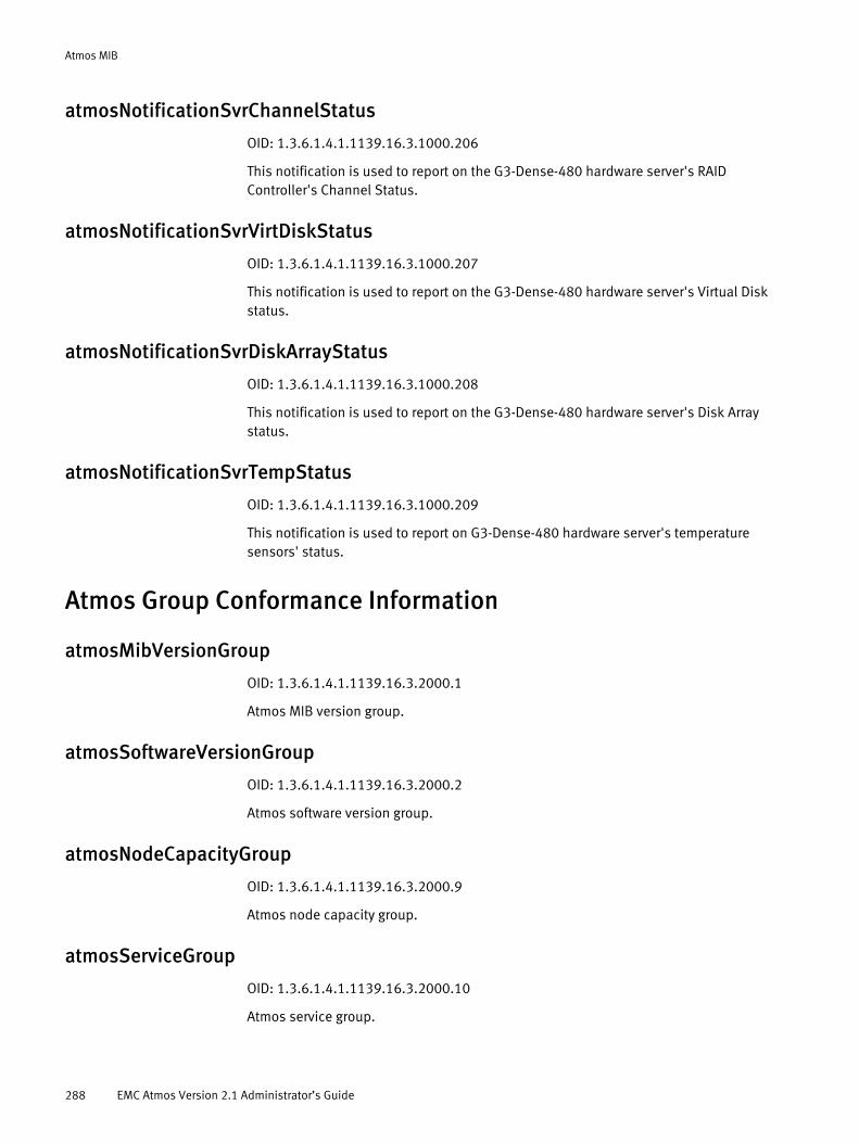
Atmos MIB
atmosNotificationSvrChannelStatus
OID: 1.3.6.1.4.1.1139.16.3.1000.206
This notification is used to report on the G3-Dense-480 hardware server's RAID Controller's Channel Status.
atmosNotificationSvrVirtDiskStatus
OID: 1.3.6.1.4.1.1139.16.3.1000.207
This notification is used to report on the G3-Dense-480 hardware server's Virtual Disk status.
atmosNotificationSvrDiskArrayStatus
OID: 1.3.6.1.4.1.1139.16.3.1000.208
This notification is used to report on the G3-Dense-480 hardware server's Disk Array status.
atmosNotificationSvrTempStatus
OID: 1.3.6.1.4.1.1139.16.3.1000.209
This notification is used to report on G3-Dense-480 hardware server's temperature sensors' status.
Atmos Group Conformance Information
atmosMibVersionGroup
OID: 1.3.6.1.4.1.1139.16.3.2000.1
Atmos MIB version group.
atmosSoftwareVersionGroup
OID: 1.3.6.1.4.1.1139.16.3.2000.2
Atmos software version group.
atmosNodeCapacityGroup
OID: 1.3.6.1.4.1.1139.16.3.2000.9
Atmos node capacity group.
atmosServiceGroup
OID: 1.3.6.1.4.1.1139.16.3.2000.10
Atmos service group.
288 EMC Atmos Version 2.1 Administrator’s Guide

Atmos MIB
atmosMetadataServiceGroup
OID: 1.3.6.1.4.1.1139.16.3.2000.11
Atmos metadata service group.
atmosStorageServiceGroup
OID: 1.3.6.1.4.1.1139.16.3.2000.12
Atmos storage service group.
atmosJobServiceGroup
OID: 1.3.6.1.4.1.1139.16.3.2000.13
Atmos job service group.
atmosWebServiceGroup
OID: 1.3.6.1.4.1.1139.16.3.2000.15
Atmos web service group.
atmosNotificationVariableGroup
OID: 1.3.6.1.4.1.1139.16.3.2000.19
Atmos notification variables group.
atmosNotificationGroup
OID: 1.3.6.1.4.1.1139.16.3.2000.20
Atmos notification group.
atmosObsolete
OID: 1.3.6.1.4.1.1139.16.3.2000.21
Atmos notification group.
Atmos obsolete notifications (no longer used) group.
Atmos Compliance Information
atmosCompliance
OID: 1.3.6.1.4.1.1139.16.3.2010.1
The compliance statement for Atmos.
Atmos Compliance Information 289

Atmos MIB
290 EMC Atmos Version 2.1 Administrator’s Guide
APPENDIX CMIB-II (RFC 1213)
This appendix provides descriptions and other information specific to MIB-II, and includes the following sections:
◆ MIB II overview...................................................................................................... 292◆ Textual conventions.............................................................................................. 292◆ Objects and types imported .................................................................................. 293◆ System group........................................................................................................ 293◆ Interfaces group.................................................................................................... 294◆ AT Group............................................................................................................... 300◆ IP group ................................................................................................................ 301◆ ICMP group ........................................................................................................... 311◆ TCP group ............................................................................................................. 314◆ UDP group ............................................................................................................ 317◆ EGP group............................................................................................................. 318◆ Transmission group .............................................................................................. 321◆ SNMP group.......................................................................................................... 322
MIB-II (RFC 1213) 291
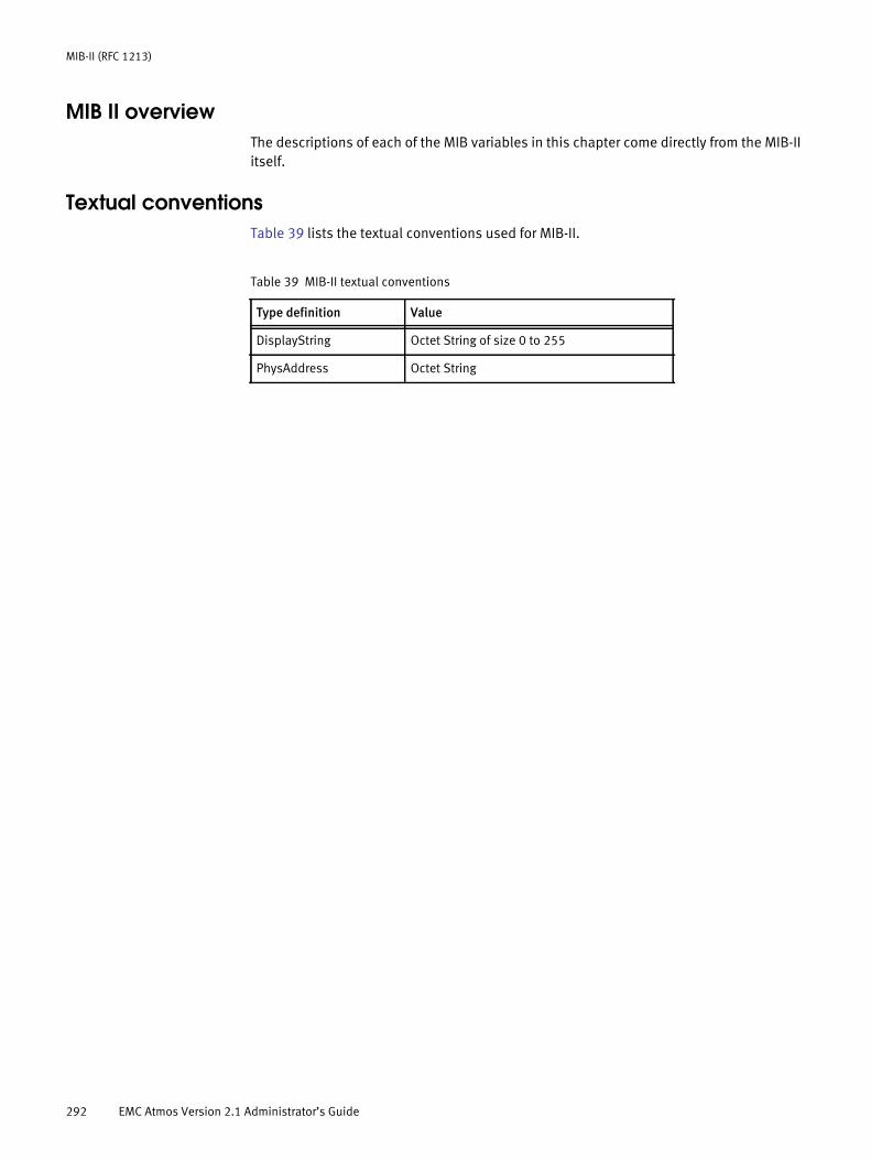
MIB-II (RFC 1213)
MIB II overviewThe descriptions of each of the MIB variables in this chapter come directly from the MIB-II itself.
Textual conventionsTable 39 lists the textual conventions used for MIB-II.
Table 39 MIB-II textual conventions
Type definition Value
DisplayString Octet String of size 0 to 255
PhysAddress Octet String
292 EMC Atmos Version 2.1 Administrator’s Guide

MIB-II (RFC 1213)
Objects and types importedThe following objects and types are imported from RFC1155-SMI:
◆ mgmt
◆ NetworkAddress
◆ IpAddress
◆ Counter
◆ Gauge
◆ TimeTicks
System groupAll systems must implement the System group. If an agent is not configured to have a value for any of the System group variables, a string of length 0 is returned.
sysDescrOID: 1.3.6.1.2.1.1.1
A textual description of the entity. This value should include the full name and version identification of the system's hardware type, software operating-system, and networking software. It is mandatory that this only contain printable ASCII characters.
sysObjectIDOID: 1.3.6.1.2.1.1.2
The vendor's authoritative identification of the network management subsystem contained in the entity. This value is allocated within the SMI enterprises subtree (1.3.6.1.4.1) and provides an easy and unambiguous means for determining ̀ what kind of box' is being managed. For example, if vendor `Flintstones, Inc.' was assigned the subtree 1.3.6.1.4.1.4242, it could assign the identifier 1.3.6.1.4.1.4242.1.1 to its `Fred Router'.
sysUpTimeOID: 1.3.6.1.2.1.1.3
The time (in hundredths of a second) since the network management portion of the system was last reinitialized.
sysContactOID: 1.3.6.1.2.1.1.4
The textual identification of the contact person for this managed node, together with information on how to contact this person.
Objects and types imported 293
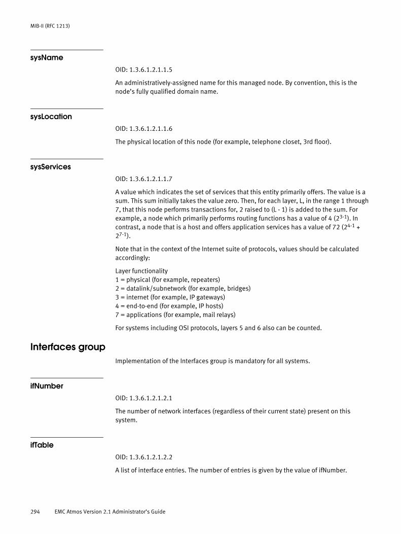
MIB-II (RFC 1213)
sysNameOID: 1.3.6.1.2.1.1.5
An administratively-assigned name for this managed node. By convention, this is the node’s fully qualified domain name.
sysLocationOID: 1.3.6.1.2.1.1.6
The physical location of this node (for example, telephone closet, 3rd floor).
sysServicesOID: 1.3.6.1.2.1.1.7
A value which indicates the set of services that this entity primarily offers. The value is a sum. This sum initially takes the value zero. Then, for each layer, L, in the range 1 through 7, that this node performs transactions for, 2 raised to (L - 1) is added to the sum. For example, a node which primarily performs routing functions has a value of 4 (23-1). In contrast, a node that is a host and offers application services has a value of 72 (24-1 + 27-1).
Note that in the context of the Internet suite of protocols, values should be calculated accordingly:
Layer functionality1 = physical (for example, repeaters)2 = datalink/subnetwork (for example, bridges)3 = internet (for example, IP gateways)4 = end-to-end (for example, IP hosts)7 = applications (for example, mail relays)
For systems including OSI protocols, layers 5 and 6 also can be counted.
Interfaces groupImplementation of the Interfaces group is mandatory for all systems.
ifNumberOID: 1.3.6.1.2.1.2.1
The number of network interfaces (regardless of their current state) present on this system.
ifTableOID: 1.3.6.1.2.1.2.2
A list of interface entries. The number of entries is given by the value of ifNumber.
294 EMC Atmos Version 2.1 Administrator’s Guide

MIB-II (RFC 1213)
ifEntryOID: 1.3.6.1.2.1.2.2.1
An interface entry containing objects at the subnetwork layer and below for a particular interface.
Interfaces group 295

MIB-II (RFC 1213)
ifIndexOID: 1.3.6.1.2.1.2.2.1.1
A unique value for each interface. Its value ranges between 1 and the value of ifNumber. The value for each interface must remain constant at least from one re-initialization of the entity's network management system to the next re- initialization.
ifDescrOID: 1.3.6.1.2.1.2.2.1.2
A textual string containing information about the interface. This string should include the name of the manufacturer, the product name and the version of the hardware interface.
ifTypeOID: 1.3.6.1.2.1.2.2.1.3
The type of interface, distinguished according to the physical/link protocol(s) immediately `below' the network layer in the protocol stack.
ifMtuOID: 1.3.6.1.2.1.2.2.1.4
The size of the largest datagram which can be sent/received on the interface, specified in octets. For interfaces that are used for transmitting network datagrams, this is the size of the largest network datagram that can be sent on the interface.
ifSpeedOID: 1.3.6.1.2.1.2.2.1.5
An estimate of the interface's current bandwidth in bits per second. For interfaces which do not vary in bandwidth or for those where no accurate estimation can be made, this object should contain the nominal bandwidth.
ifPhysAddressOID: 1.3.6.1.2.1.2.2.1.6
The interface's address at the protocol layer immediately `below' the network layer in the protocol stack. For interfaces which do not have such an address (e.g., a serial line), this object should contain an octet string of zero length.
ifAdminStatusOID: 1.3.6.1.2.1.2.2.1.7
The desired state of the interface. The testing (3) state indicates that no operational packets can be passed.
296 EMC Atmos Version 2.1 Administrator’s Guide

MIB-II (RFC 1213)
ifOperStatusOID: 1.3.6.1.2.1.2.2.1.8
The current operational state of the interface. The testing (3) state indicates that no operational packets can be passed.
ifLastChangeOID: 1.3.6.1.2.1.2.2.1.9
The value of sysUpTime at the time the interface entered its current operational state. If the current state was entered prior to the last re-initialization of the local network management subsystem, then this object contains a zero value.
ifInOctetsOID: 1.3.6.1.2.1.2.2.1.10
The total number of octets received on the interface, including framing characters.
Interfaces group 297

MIB-II (RFC 1213)
ifInUcastPktsOID: 1.3.6.1.2.1.2.2.1.11
The number of subnetwork-unicast packets delivered to a higher-layer protocol.
ifInNUcastPktsOID: 1.3.6.1.2.1.2.2.1.12
The number of nonunicast packets (for example, subnetwork-broadcast or subnetwork-multicast) delivered to a higher-layer protocol.
ifInDiscardsOID: 1.3.6.1.2.1.2.2.1.13
The number of inbound packets which were chosen to be discarded even though no errors had been detected to prevent their being deliverable to a higher-layer protocol. One possible reason for discarding such a packet could be to free up buffer space.
ifInErrorsOID: 1.3.6.1.2.1.2.2.1.14
The number of inbound packets that contained errors preventing them from being deliverable to a higher-layer protocol.
ifInUnknownProtosOID: 1.3.6.1.2.1.2.2.1.15
The number of packets received via the interface which were discarded because of an unknown or unsupported protocol.
298 EMC Atmos Version 2.1 Administrator’s Guide

MIB-II (RFC 1213)
ifOutOctetsOID: 1.3.6.1.2.1.2.2.1.16
The total number of octets transmitted out of the interface, including framing characters.
ifOutUcastPktsOID: 1.3.6.1.2.1.2.2.1.17
The total number of packets that were requested, by higher-level protocols, to be transmitted to a subnetwork-unicast address, including those that were discarded or not sent.
ifOutNUcastPktsOID: 1.3.6.1.2.1.2.2.1.18
he total number of packets that higher-level protocols requested be transmitted to a non- unicast (i.e., a subnetwork-broadcast or subnetwork-multicast) address, including those that were discarded or not sent.
ifOutDiscardsOID: 1.3.6.1.2.1.2.2.1.19
The number of outbound packets which were chosen to be discarded even though no errors had been detected to prevent their being transmitted. One possible reason for discarding such a packet could be to free up buffer space.
ifOutErrorsOID: 1.3.6.1.2.1.2.2.1.20
The number of outbound packets that could not be transmitted because of errors.
Interfaces group 299

MIB-II (RFC 1213)
ifOutQLenOID: 1.3.6.1.2.1.2.2.1.21
The length of the output packet queue (in packets).
ifSpecificOID: 1.3.6.1.2.1.2.2.1.22
A reference to MIB definitions specific to the particular media being used to realize the interface. For example, if the interface is realized by an ethernet, then the value of this object refers to a document defining objects specific to ethernet. If this information is not present, its value should be set to the OBJECT IDENTIFIER { 0 0 }, which is a syntatically valid object identifier, and any conformant implementation of ASN.1 and BER must be able to generate and recognize this value.
AT GroupImplementation of the Address Translation group is mandatory for all systems. Note, however, that this group is deprecated by MIB-II. From MIB-II onward, each network protocol group contains its own address translation tables.
atTableOID: 1.3.6.1.2.1.3.1
The Address Translation tables contain the NetworkAddress to `physical' address equivalences. Some interfaces do not use translation tables for determining address equivalences (e.g., DDN-X.25 has an algorithmic method); if all interfaces are of this type, then the Address Translation table is empty, i.e., has zero entries.
atEntryOID: 1.3.6.1.2.1.3.1.1
Each entry contains one network address to physical address equivalence.
atIfIndexOID: 1.3.6.1.2.1.3.1.1.1
The interface on which this entry's equivalence is effective. The interface identified by a particular value of this index is the same interface as identified by the same value of ifIndex.
atPhysAddressOID: 1.3.6.1.2.1.3.1.1.2
The media-dependent `physical' address. Setting this object to a null string (one of zero length) has the effect of invaliding the corresponding entry in the atTable object. That is, it effectively dissasociates the interface identified with said entry from the mapping
300 EMC Atmos Version 2.1 Administrator’s Guide
MIB-II (RFC 1213)
identified with said entry. It is an implementation-specific matter as to whether the agent removes an invalidated entry from the table. Accordingly, management stations must be prepared to receive tabular information from agents that corresponds to entries not currently in use. Proper interpretation of such entries requires examination of the relevant atPhysAddress object.
atNetAddressOID: 1.3.6.1.2.1.3.1.1.3
The NetworkAddress (e.g., the IP address) corresponding to the media-dependent `physical' address.
IP groupImplementation of the IP group is mandatory for all systems.
ipForwardingOID: 1.3.6.1.2.1.4.1
The indication of whether this entity is acting as an IP gateway in respect to the forwarding of datagrams received by, but not addressed to, this entity. IP gateways forward datagrams. IP hosts do not (except those source-routed via the host). Note that for some managed nodes, this object may take on only a subset of the values possible. Accordingly, it is appropriate for an agent to return a `badValue' response if a management station attempts to change this object to an inappropriate value.
ipDefaultTTLOID: 1.3.6.1.2.1.4.2
The default value inserted into the Time-To-Live field of the IP header of datagrams originated at this entity, whenever a TTL value is not supplied by the transport layer protocol.
ipInReceivesOID: 1.3.6.1.2.1.4.3
The total number of input datagrams received from interfaces, including those received in error.
ipInHdrErrorsOID: 1.3.6.1.2.1.4.4
The number of input datagrams discarded due to errors in their IP headers, including bad checksums, version number mismatch, other format errors, time-to-live exceeded, errors discovered in processing their IP options, etc.
IP group 301

MIB-II (RFC 1213)
ipInAddrErrorsOID: 1.3.6.1.2.1.4.5
The number of input datagrams discarded because the IP address in their IP header's destination field was not a valid address to be received at this entity. This count includes invalid addresses (e.g., 0.0.0.0) and addresses of unsupported Classes (e.g., Class E). For entities which are not IP Gateways and therefore do not forward datagrams, this counter includes datagrams discarded because the destination address was not a local address.
302 EMC Atmos Version 2.1 Administrator’s Guide
MIB-II (RFC 1213)
ipForwDatagramsOID: 1.3.6.1.2.1.4.6
The number of input datagrams for which this entity was not their final IP destination, as a result of which an attempt was made to find a route to forward them to that final destination. In entities which do not act as IP Gateways, this counter will include only those packets which were Source-Routed via this entity, and the Source- Route option processing was successful.
ipInUnknownProtosOID: 1.3.6.1.2.1.4.7
The number of locally-addressed datagrams received successfully but discarded because of an unknown or unsupported protocol.
ipInDiscardsOID: 1.3.6.1.2.1.4.8
The number of input IP datagrams for which no problems were encountered to prevent their continued processing, but which were discarded (e.g., for lack of buffer space). Note that this counter does not include any datagrams discarded while awaiting re-assembly.
ipInDeliversOID: 1.3.6.1.2.1.4.9
The total number of input datagrams successfully delivered to IP user-protocols (including ICMP).
ipOutRequestsOID: 1.3.6.1.2.1.4.10
The total number of IP datagrams which local IP user-protocols (including ICMP) supplied to IP in requests for transmission. Note that this counter does not include any datagrams counted in ipForwDatagrams.
ipOutDiscardsOID: 1.3.6.1.2.1.4.11
The number of output IP datagrams for which no problem was encountered to prevent their transmission to their destination, but which were discarded (e.g., for lack of buffer space). Note that this counter would include datagrams counted in ipForwDatagrams if any such packets met this (discretionary) discard criterion.
ipOutNoRoutesOID: 1.3.6.1.2.1.4.12
IP group 303
MIB-II (RFC 1213)
The number of IP datagrams discarded because no route could be found to transmit them to their destination. Note that this counter includes any packets counted in ipForwDatagrams which meet this `no-route' criterion. Note that this includes any datagarms which a host cannot route because all of its default gateways are down..
ipReasmTimeoutOID: 1.3.6.1.2.1.4.13
The maximum number of seconds which received fragments are held while they are awaiting reassembly at this entity.
ipReasmReqdsOID: 1.3.6.1.2.1.4.14
The number of IP fragments received which needed to be reassembled at this entity.
ipReasmOKsOID: 1.3.6.1.2.1.4.15
The number of IP datagrams successfully re- assembled.
304 EMC Atmos Version 2.1 Administrator’s Guide

MIB-II (RFC 1213)
ipReasmFailsOID: 1.3.6.1.2.1.4.16
The number of failures detected by the IP re- assembly algorithm (for whatever reason: timed out, errors, etc). Note that this is not necessarily a count of discarded IP fragments since some algorithms (notably the algorithm in RFC 815) can lose track of the number of fragments by combining them as they are received.
ipFragOKsOID: 1.3.6.1.2.1.4.17
The number of IP datagrams that have been successfully fragmented at this entity.
ipFragFailsOID: 1.3.6.1.2.1.4.18
The number of IP datagrams that have been discarded because they needed to be fragmented at this entity but could not be, e.g., because their Don't Fragment flag was set.
ipFragCreatesOID: 1.3.6.1.2.1.4.19
The number of IP datagram fragments that have been generated as a result of fragmentation at this entity.
ipAddrTableOID: 1.3.6.1.2.1.4.20
The table of addressing information relevant to this entity's IP addresses.
IP group 305

MIB-II (RFC 1213)
ipAddrEntryOID: 1.3.6.1.2.1.4.20.1
The addressing information for one of this entity's IP addresses.
ipAdEntAddrOID: 1.3.6.1.2.1.4.20.1.1
The IP address to which this entry's addressing information pertains.
ipAdEntIfIndexOID: 1.3.6.1.2.1.4.20.1.2
The index value which uniquely identifies the interface to which this entry is applicable. The interface identified by a particular value of this index is the same interface as identified by the same value of ifIndex.
ipAdEntNetMaskOID: 1.3.6.1.2.1.4.20.1.3
The subnet mask associated with the IP address of this entry. The value of the mask is an IP address with all the network bits set to 1 and all the hosts bits set to 0.
ipAdEntBcastAddrOID: 1.3.6.1.2.1.4.20.1.4
The value of the least-significant bit in the IP broadcast address used for sending datagrams on the (logical) interface associated with the IP address of this entry. For example, when the Internet standard all-ones broadcast address is used, the value will be 1. This value applies to both the subnet and network broadcasts addresses used by the entity on this (logical) interface.
306 EMC Atmos Version 2.1 Administrator’s Guide

MIB-II (RFC 1213)
ipAdEntReasmMaxSizeOID: 1.3.6.1.2.1.4.20.1.5
The size of the largest IP datagram which this entity can re-assemble from incoming IP fragmented datagrams received on this interface.
ipRouteTableOID: 1.3.6.1.2.1.4.21
This entity's IP Routing table.
ipRouteEntryOID: 1.3.6.1.2.1.4.21.1
A route to a particular destination.
ipRouteDestOID: 1.3.6.1.2.1.4.21.1.1
The destination IP address of this route. An entry with a value of 0.0.0.0 is considered a default route. Multiple routes to a single destination can appear in the table, but access to such multiple entries is dependent on the table- access mechanisms defined by the network management protocol in use.
ipRouteIfIndexOID: 1.3.6.1.2.1.4.21.1.2
The index value which uniquely identifies the local interface through which the next hop of this route should be reached. The interface identified by a particular value of this index is the same interface as identified by the same value of ifIndex.
IP group 307

MIB-II (RFC 1213)
ipRouteMetric1OID: 1.3.6.1.2.1.4.21.1.3
The primary routing metric for this route. The semantics of this metric are determined by the routing-protocol specified in the route's ipRouteProto value. If this metric is not used, its value should be set to -1.
ipRouteMetric2OID: 1.3.6.1.2.1.4.21.1.4
An alternate routing metric for this route. The semantics of this metric are determined by the routing-protocol specified in the route's ipRouteProto value. If this metric is not used, its value should be set to -1.
ipRouteMetric3OID: 1.3.6.1.2.1.4.21.1.5
An alternate routing metric for this route. The semantics of this metric are determined by the routing-protocol specified in the route's ipRouteProto value. If this metric is not used, its value should be set to -1.
ipRouteMetric4OID: 1.3.6.1.2.1.4.21.1.6
An alternate routing metric for this route. The semantics of this metric are determined by the routing-protocol specified in the route's ipRouteProto value. If this metric is not used, its value should be set to -1.
ipRouteNextHopOID: 1.3.6.1.2.1.4.21.1.7
The IP address of the next hop of this route. (In the case of a route bound to an interface which is realized via a broadcast media, the value of this field is the agent's IP address on that interface.)
ipRouteTypeOID: 1.3.6.1.2.1.4.21.1.8
The type of route. Note that the values direct(3) and indirect(4) refer to the notion of direct and indirect routing in the IP architecture. Setting this object to the value invalid(2) has the effect of invalidating the corresponding entry in the ipRouteTable object. That is, it effectively dissasociates the destination identified with said entry from the route identified with said entry. It is an implementation-specific matter as to whether the agent removes an invalidated entry from the table. Accordingly, management stations must be prepared to receive tabular information from agents that corresponds to entries not currently in use. Proper interpretation of such entries requires examination of the relevant ipRouteType object.
308 EMC Atmos Version 2.1 Administrator’s Guide

MIB-II (RFC 1213)
ipRouteProtoOID: 1.3.6.1.2.1.4.21.1.9
The routing mechanism via which this route was learned. Inclusion of values for gateway routing protocols is not intended to imply that hosts should support those protocols.
ipRouteAgeOID: 1.3.6.1.2.1.4.21.1.10
The number of seconds since this route was last updated or otherwise determined to be correct. Note that no semantics of `too old' can be implied except through knowledge of the routing protocol by which the route was learned.
ipRouteMaskOID: 1.3.6.1.2.1.4.21.1.11
The mask to be logical-ANDed with the destination address before being compared to the value in the ipRouteDest field. For those systems that do not support arbitrary subnet masks, an agent constructs the value of the ipRouteMask by determining whether the value of the correspondent ipRouteDest field belong to a class-A, B, or C network, and then using one of the following:
If the value of the ipRouteDest is 0.0.0.0 (a default route), then the mask value is also 0.0.0.0. It should be noted that all IP routing subsystems implicitly use this mechanism.
ipRouteMetric5OID: 1.3.6.1.2.1.4.21.1.12
An alternate routing metric for this route. The semantics of this metric are determined by the routing-protocol specified in the route's ipRouteProto value. If this metric is not used, its value should be set to -1.
ipRouteInfoOID: 1.3.6.1.2.1.4.21.1.13
A reference to MIB definitions specific to the particular routing protocol which is responsible for this route, as determined by the value specified in the route's ipRouteProto value. If this information is not present, its value should be set to the OBJECT IDENTIFIER { 0 0 }, which is a syntactically valid object identifier, and any conformant implementation of ASN.1 and BER must be able to generate and recognize this value.
mask network
255.0.0.0 class-A
255.255.0.0 class-B
255.255.255.0 class-C
IP group 309
MIB-II (RFC 1213)
ipNetToMediaTableOID: 1.3.6.1.2.1.4.22
The IP Address Translation table used for mapping from IP addresses to physical addresses.
ipNetToMediaEntryOID: 1.3.6.1.2.1.4.22.1
Each entry contains one IP address to physical address equivalence.
ipNetToMediaIfIndexOID: 1.3.6.1.2.1.4.22.1.1
The interface on which this entry's equivalence is effective. The interface identified by a particular value of this index is the same interface as identified by the same value of ifIndex.
ipNetToMediaPhysAddressOID: 1.3.6.1.2.1.4.22.1.2
The media-dependent physical address.
ipNetToMediaNetAddressOID: 1.3.6.1.2.1.4.22.1.3
The IpAddress corresponding to the media-dependent physical address.
ipNetToMediaTypeOID: 1.3.6.1.2.1.4.22.1.4
The type of mapping.
Setting this object to the value invalid(2) has the effect of invalidating the corresponding entry in the ipNetToMediaTable. That is, it effectively dissasociates the interface identified with said entry from the mapping identified with said entry. It is an implementation-specific matter as to whether the agent removes an invalidated entry from the table. Accordingly, management stations must be prepared to receive tabular information from agents that corresponds to entries not currently in use. Proper interpretation of such entries requires examination of the relevant ipNetToMediaType object.
ipRoutingDiscardsOID: 1.3.6.1.2.1.4.23
310 EMC Atmos Version 2.1 Administrator’s Guide
MIB-II (RFC 1213)
The number of routing entries which were chosen to be discarded even though they are valid. One possible reason for discarding such an entry could be to free-up buffer space for other routing entries.
ICMP groupImplementation of the ICMP group is mandatory for all systems.
icmpInMsgsOID: 1.3.6.1.2.1.5.1
The total number of ICMP messages which the entity received. Note that this counter includes all those counted by icmpInErrors.
icmpInErrorsOID: 1.3.6.1.2.1.5.2
The number of ICMP messages which the entity received but determined as having ICMP-specific errors (bad ICMP checksums, bad length, etc.).
icmpInDestUnreachsOID: 1.3.6.1.2.1.5.3
The number of ICMP Destination Unreachable messages received.
icmpInTimeExcdsOID: 1.3.6.1.2.1.5.4
The number of ICMP Time Exceeded messages received.
ICMP group 311
MIB-II (RFC 1213)
icmpInParmProbsOID: 1.3.6.1.2.1.5.5
The number of ICMP Parameter Problem messages received.
icmpInSrcQuenchsOID: 1.3.6.1.2.1.5.6
The number of ICMP Source Quench messages received.
icmpInRedirectsOID: 1.3.6.1.2.1.5.7
The number of ICMP Redirect messages received.
icmpInEchosOID: 1.3.6.1.2.1.5.8
The number of ICMP Echo (request) messages received.
icmpInEchoRepsOID: 1.3.6.1.2.1.5.9
The number of ICMP Echo Reply messages received.
icmpInTimestampsOID: 1.3.6.1.2.1.5.10
The number of ICMP Timestamp (request) messages received.
icmpInTimestampRepsOID: 1.3.6.1.2.1.5.11
The number of ICMP Timestamp Reply messages received.
icmpInAddrMasksOID: 1.3.6.1.2.1.5.12
The number of ICMP Address Mask Request messages received.
icmpInAddrMaskRepsOID: 1.3.6.1.2.1.5.13
The number of ICMP Address Mask Reply messages received.
312 EMC Atmos Version 2.1 Administrator’s Guide
MIB-II (RFC 1213)
icmpOutMsgsOID: 1.3.6.1.2.1.5.14
The total number of ICMP messages which this entity attempted to send. Note that this counter includes all those counted by icmpOutErrors.
icmpOutErrorsOID: 1.3.6.1.2.1.5.15
The number of ICMP messages that this entity did not send due to problems discovered within ICMP such as a lack of buffers. This value should not include errors discovered outside the ICMP layer such as the inability of IP to route the resultant datagram. In some implementations there might be no types of error that contribute to this counter's value.
icmpOutDestUnreachsOID: 1.3.6.1.2.1.5.16
The number of ICMP Destination Unreachable messages sent.
icmpOutTimeExcdsOID: 1.3.6.1.2.1.5.17
The number of ICMP Time Exceeded messages sent.
icmpOutParmProbsOID: 1.3.6.1.2.1.5.18
The number of ICMP Parameter Problem messages sent.
icmpOutSrcQuenchsOID: 1.3.6.1.2.1.5.19
The number of ICMP Source Quench messages sent.
icmpOutRedirectsOID: 1.3.6.1.2.1.5.20
The number of ICMP Redirect messages sent. For a host, this object is always zero, since hosts do not send redirects.
icmpOutEchosOID: 1.3.6.1.2.1.5.21
The number of ICMP Echo (request) messages sent.
ICMP group 313

MIB-II (RFC 1213)
icmpOutEchoRepsOID: 1.3.6.1.2.1.5.22
The number of ICMP Echo Reply messages sent.
icmpOutTimestampsOID: 1.3.6.1.2.1.5.23
The number of ICMP Timestamp (request) messages sent.
icmpOutTimestampRepsOID: 1.3.6.1.2.1.5.24
The number of ICMP Timestamp Reply messages sent.
icmpOutAddrMasksOID: 1.3.6.1.2.1.5.25
The number of ICMP Address Mask Request messages sent.
icmpOutAddrMaskRepsOID: 1.3.6.1.2.1.5.26
The number of ICMP Address Mask Reply messages sent.
TCP groupImplementation of the TCP group is mandatory for all systems that implement the TCP.
Instances of object types that represent information about a particular TCP connection are transient; they persist only as long as the connection in question.
tcpRtoAlgorithmOID: 1.3.6.1.2.1.6.1
The algorithm used to determine the time-out value used for retransmitting unacknowledged octets.
tcpRtoMinOID: 1.3.6.1.2.1.6.2
The minimum value permitted by a TCP implementation for the retransmission time-out, measured in milliseconds. More refined semantics for objects of this type depend upon the algorithm used to determine the retransmission time-out. In particular, when the time-out algorithm is 3 (rsre), an object of this type has the semantics of the LBOUND quantity described in RFC 793.
314 EMC Atmos Version 2.1 Administrator’s Guide

MIB-II (RFC 1213)
tcpRtoMaxOID: 1.3.6.1.2.1.6.3
The maximum value permitted by a TCP implementation for the retransmission time-out, measured in milliseconds. More refined semantics for objects of this type depend upon the algorithm used to determine the retransmission time-out. In particular, when the time-out algorithm is 3 (rsre), an object of this type has the semantics of the UBOUND quantity described in RFC 793.
tcpMaxConnOID: 1.3.6.1.2.1.6.4
The limit on the total number of TCP connections the entity can support. In entities where the maximum number of connections is dynamic, this object should contain the value -1.
tcpActiveOpensOID: 1.3.6.1.2.1.6.5
The number of times TCP connections have made a direct transition to the SYN-SENT state from the CLOSED state.
tcpPassiveOpensOID: 1.3.6.1.2.1.6.6
The number of times TCP connections have made a direct transition to the SYN-RCVD state from the LISTEN state.
tcpAttemptFailsOID: 1.3.6.1.2.1.6.7
The number of times TCP connections have made a direct transition to the CLOSED state from either the SYN-SENT state or the SYN-RCVD state, plus the number of times TCP connections have made a direct transition to the LISTEN state from the SYN-RCVD state.
tcpEstabResetsOID: 1.3.6.1.2.1.6.8
The number of times TCP connections have made a direct transition to the CLOSED state from either the ESTABLISHED state or the CLOSE-WAIT state.
tcpCurrEstabOID: 1.3.6.1.2.1.6.9
The number of TCP connections for which the current state is either ESTABLISHED or CLOSE-WAIT.
TCP group 315

MIB-II (RFC 1213)
tcpInSegsOID: 1.3.6.1.2.1.6.10
The total number of segments received, including those received in error. This count includes segments received on currently established connections.
tcpOutSegsOID: 1.3.6.1.2.1.6.11
The total number of segments sent, including those on current connections but excluding those containing only retransmitted octets.
tcpRetransSegs1.3.6.1.2.1.6.12
The total number of segments retransmitted; that is, the number of TCP segments transmitted containing one or more previously transmitted octets.
TCP Connection TableThe TCP connection table contains information about this entity's existing TCP connections.
tcpConnTableOID: 1.3.6.1.2.1.6.13
A table containing TCP connection-specific information.
tcpConnEntryOID: 1.3.6.1.2.1.6.13.1
Information about a particular current TCP connection. An object of this type is transient, in that it ceases to exist when (or soon after) the connection makes the transition to the CLOSED state.
tcpConnStateOID: 1.3.6.1.2.1.6.13.1.1
The state of this TCP connection.
The only value that might be set by a management station is deleteTCB (12). Accordingly, it is appropriate for an agent to return a badValue response if a management station attempts to set this object to any other value.
If a management station sets this object to the value delete12 (TCB), then this has the effect of deleting the TCB (as defined in RFC 793) of the corresponding connection on the managed node, resulting in immediate termination of the connection.
316 EMC Atmos Version 2.1 Administrator’s Guide

MIB-II (RFC 1213)
As an implementation-specific option, a RST segment might be sent from the managed node to the other TCP endpoint (note, however, that RST segments are not sent reliably).
tcpConnLocalAddressOID: 1.3.6.1.2.1.6.13.1.2
The local IP address for this TCP connection. In the case of a connection in the listen state that is willing to accept connections for any IP interface associated with the node, the value 0.0.0.0 is used.
tcpConnLocalPortOID: 1.3.6.1.2.1.6.13.1.3
The local port number for this TCP connection.
tcpConnRemAddressOID: 1.3.6.1.2.1.6.13.1.4
The remote IP address for this TCP connection.
tcpConnRemPortOID: 1.3.6.1.2.1.6.13.1.5
The remote port number for this TCP connection.
tcpInErrsOID: 1.3.6.1.2.1.6.14
The total number of segments received in error (for example, bad TCP checksums).
tcpOutRstsOID: 1.3.6.1.2.1.6.15
The number of TCP segments sent containing the RST flag.
UDP groupImplementation of the UDP group is mandatory for all systems that implement the UDP.
udpInDatagramsOID: 1.3.6.1.2.1.7.1
The total number of UDP datagrams delivered to UDP users.
UDP group 317
MIB-II (RFC 1213)
udpNoPortsOID: 1.3.6.1.2.1.7.2
The total number of received UDP datagrams for which there was no application at the destination port.
udpInErrorsOID: 1.3.6.1.2.1.7.3
The number of received UDP datagrams that could not be delivered for reasons other than the lack of an application at the destination port.
udpOutDatagramsOID: 1.3.6.1.2.1.7.4
The total number of UDP datagrams sent from this entity.
udpTableOID: 1.3.6.1.2.1.7.5
A table containing UDP listener information.
udpEntryOID: 1.3.6.1.2.1.7.5.1
Information about a particular current UDP listener.
udpLocalAddressOID: 1.3.6.1.2.1.7.5.1.1
The local IP address for this UDP listener. In the case of a UDP listener that is willing to accept datagrams for any IP interface associated with the node, the value 0.0.0.0 is used.
udpLocalPortOID: 1.3.6.1.2.1.7.5.1.2
The local port number for this UDP listener.
EGP groupImplementation of the EGP group is mandatory for all systems which implement the EGP.
egpInMsgs
OID: 1.3.6.1.2.1.8.1
318 EMC Atmos Version 2.1 Administrator’s Guide

MIB-II (RFC 1213)
The number of EGP messages received without error.
egpInErrors
OID: 1.3.6.1.2.1.8.2
The number of EGP messages received that proved to be in error.
egpOutMsgs
OID: 1.3.6.1.2.1.8.3
The total number of locally generated EGP messages.
egpOutErrors
OID: 1.3.6.1.2.1.8.4
The number of locally generated EGP messages not sent due to resource limitations within an EGP entity.
egpNeighTable
OID: 1.3.6.1.2.1.8.5
The EGP neighbor table.
egpNeighEntryOID: 1.3.6.1.2.1.8.5.1
Information about this entity's relationship with a particular EGP neighbor.
egpNeighState
OID: 1.3.6.1.2.1.8.5.1.1
The EGP state of the local system with respect to this entry's EGP neighbor. Each EGP state is represented by a value that is one greater than the numerical value associated with said state in RFC 904.
egpNeighAddr
OID: 1.3.6.1.2.1.8.5.1.2
The IP address of this entry's EGP neighbor.
egpNeighAs
OID: 1.3.6.1.2.1.8.5.1.3
The autonomous system of this EGP peer. Zero should be specified if the autonomous system number of the neighbor is not yet known.
egpNeighInMsgs
OID: 1.3.6.1.2.1.8.5.1.4
The number of EGP messages received without error from this EGP peer.
EGP group 319

MIB-II (RFC 1213)
egpNeighInErrs
OID: 1.3.6.1.2.1.8.5.1.5
The number of EGP messages received from this EGP peer that proved to be in error (e.g., bad EGP checksum).
egpNeighOutMsgs
OID: 1.3.6.1.2.1.8.5.1.6
The number of locally generated EGP messages to this EGP peer.
egpNeighOutErrs
OID: 1.3.6.1.2.1.8.5.1.7
The number of locally generated EGP messages not sent to this EGP peer due to resource limitations within an EGP entity.
egpNeighInErrMsgs
OID: 1.3.6.1.2.1.8.5.1.8
The number of EGP-defined error messages received from this EGP peer.
egpNeighOutErrMsgs
OID: 1.3.6.1.2.1.8.5.1.9
The number of EGP-defined error messages sent to this EGP peer.
egpNeighStateUps
OID: 1.3.6.1.2.1.8.5.1.10
The number of EGP state transitions to the UP state with this EGP peer.
egpNeighStateDowns
OID: 1.3.6.1.2.1.8.5.1.11
The number of EGP state transitions from the UP state to any other state with this EGP peer.
egpNeighIntervalHello
OID: 1.3.6.1.2.1.8.5.1.12
The interval between EGP Hello command retransmissions (in hundredths of a second). This represents the t1 timer as defined in RFC 904.
egpNeighIntervalPoll
OID: 1.3.6.1.2.1.8.5.1.13
The interval between EGP poll command retransmissions (in hundredths of a second). This represents the t3 timer as defined in RFC 904.
egpNeighMode
OID: 1.3.6.1.2.1.8.5.1.14
320 EMC Atmos Version 2.1 Administrator’s Guide
MIB-II (RFC 1213)
The polling mode of this EGP entity, either passive or active.
egpNeighEventTrigger
OID: 1.3.6.1.2.1.8.5.1.15
A control variable used to trigger operator- initiated Start and Stop events. When read, this variable always returns the most recent value that egpNeighEventTrigger was set to. If it has not been set since the last initialization of the network management subsystem on the node, it returns a value of `stop'. When set, this variable causes a Start or Stop event on the specified neighbor, as specified on pages 8-10 of RFC 904. Briefly, a Start event causes an Idle peer to begin neighbor acquisition and a non-Idle peer to reinitiate neighbor acquisition. A stop event causes a non-Idle peer to return to the Idle state until a Start event occurs, either via egpNeighEventTrigger or otherwise.
egpAs
OID: 1.3.6.1.2.1.8.6
The autonomous system number of this EGP entity.
Transmission groupBased on the transmission media underlying each interface on a system, the corresponding portion of the Transmission group is mandatory for that system.
When Internet-standard definitions for managing transmission media are defined, the transmission group is used to provide a prefix for the names of those objects.
Typically, such definitions reside in the experimental portion of the MIB until they are "proven", then as a part of the Internet standardization process, the definitions are accordingly elevated and a new object identifier, under the transmission group is defined. By convention, the name assigned is:
type OBJECT IDENTIFIER ::= { transmission number }
where "type" is the symbolic value used for the media in the ifType column of the ifTable object, and "number" is the actual integer value corresponding to the symbol.
Transmission group 321
MIB-II (RFC 1213)
SNMP groupImplementation of the SNMP group is mandatory for all systems that support an SNMP protocol entity. Some of the objects defined next are zero-valued in those SNMP implementations that are optimized to support only those functions specific to either a management agent or a management station. All of the objects that follow refer to an SNMP entity, and there might be several SNMP entities residing on a managed node (for example, if the node is acting as a management station).
snmpInPktsOID: 1.3.6.1.2.1.11.1
The total number of messages delivered to the SNMP entity from the transport service.
snmpOutPktsOID: 1.3.6.1.2.1.11.2
The total number of SNMP messages that were passed from the SNMP protocol entity to the transport service.
snmpInBadVersionsOID: 1.3.6.1.2.1.11.3
The total number of SNMP messages that were delivered to the SNMP protocol entity and were for an unsupported SNMP version.
snmpInBadCommunityNamesOID: 1.3.6.1.2.1.11.4
The total number of SNMP messages delivered to the SNMP protocol entity that used a SNMP community name not known to said entity.
322 EMC Atmos Version 2.1 Administrator’s Guide
MIB-II (RFC 1213)
snmpInBadCommunityUsesOID: 1.3.6.1.2.1.11.5
The total number of SNMP messages delivered to the SNMP protocol entity that represented an SNMP operation that was not allowed by the SNMP community named in the message.
snmpInASNParseErrsOID: 1.3.6.1.2.1.11.6
The total number of ASN.1 or BER errors encountered by the SNMP protocol entity when decoding received SNMP messages.
snmpInTooBigsOID: 1.3.6.1.2.1.11.8
The total number of SNMP PDUs that were delivered to the SNMP protocol entity and for which the value of the error-status field is “tooBig.”
snmpInNoSuchNamesOID: 1.3.6.1.2.1.11.9
The total number of SNMP PDUs that were delivered to the SNMP protocol entity and for which the value of the error-status field is “noSuchName.”
snmpInBadValuesOID: 1.3.6.1.2.1.11.10
The total number of SNMP PDUs that were delivered to the SNMP protocol entity and for which the value of the error-status field is “badValue.”
SNMP group 323
MIB-II (RFC 1213)
snmpInReadOnlysOID: 1.3.6.1.2.1.11.11
The total number valid SNMP PDUs that were delivered to the SNMP protocol entity and for which the value of the error-status field is “readOnly.”
It is a protocol error to generate an SNMP PDU that contains the value “readOnly” in the error-status field; as such, this object is provided as a means of detecting incorrect implementations of the SNMP.
snmpInGenErrsOID: 1.3.6.1.2.1.11.12
The total number of SNMP PDUs that were delivered to the SNMP protocol entity and for which the value of the error-status field is “genErr.”
snmpInTotalReqVarsOID: 1.3.6.1.2.1.11.13
The total number of MIB objects that have been retrieved successfully by the SNMP protocol entity as the result of receiving valid SNMP Get-Request and Get-Next PDUs.
snmpInTotalSetVarsOID: 1.3.6.1.2.1.11.14
The total number of MIB objects that have been altered successfully by the SNMP protocol entity as the result of receiving valid SNMP Set-Request PDUs.
snmpInGetRequestsOID: 1.3.6.1.2.1.11.15
The total number of SNMP Get-Request PDUs that have been accepted and processed by the SNMP protocol entity.
snmpInGetNextsOID: 1.3.6.1.2.1.11.16
The total number of SNMP Get-Next PDUs that have been accepted and processed by the SNMP protocol entity.
snmpInSetRequestsOID: 1.3.6.1.2.1.11.17
The total number of SNMP Set-Request PDUs that have been accepted and processed by the SNMP protocol entity.
324 EMC Atmos Version 2.1 Administrator’s Guide
MIB-II (RFC 1213)
snmpInGetResponsesOID: 1.3.6.1.2.1.11.18
The total number of SNMP Get-Response PDUs that have been accepted and processed by the SNMP protocol entity.
snmpInTrapsOID: 1.3.6.1.2.1.11.19
The total number of SNMP Trap PDUs that have been accepted and processed by the SNMP protocol entity.
snmpOutTooBigsOID: 1.3.6.1.2.1.11.20
The total number of SNMP PDUs that were generated by the SNMP protocol entity and for which the value of the error-status field is “tooBig.”
snmpOutNoSuchNamesOID: 1.3.6.1.2.1.11.21
The total number of SNMP PDUs that were generated by the SNMP protocol entity and for which the value of the error-status field is “noSuchName.”
snmpOutBadValuesOID: 1.3.6.1.2.1.11.22
The total number of SNMP PDUs that were generated by the SNMP protocol entity and for which the value of the error-status field is “badValue.”
snmpOutGenErrsOID: 1.3.6.1.2.1.11.24
The total number of SNMP PDUs that were generated by the SNMP protocol entity and for which the value of the error-status field is “genErr.”
snmpOutGetRequestsOID: 1.3.6.1.2.1.11.25
The total number of SNMP Get-Request PDUs that have been generated by the SNMP protocol entity.
snmpOutGetNextsOID: 1.3.6.1.2.1.11.26
SNMP group 325
MIB-II (RFC 1213)
The total number of SNMP Get-Next PDUs that have been generated by the SNMP protocol entity.
snmpOutSetRequestsOID: 1.3.6.1.2.1.11.27
The total number of SNMP Set-Request PDUs that have been generated by the SNMP protocol entity.
snmpOutGetResponsesOID: 1.3.6.1.2.1.11.28
The total number of SNMP Get-Response PDUs that have been generated by the SNMP protocol entity.
snmpOutTrapsOID: 1.3.6.1.2.1.11.29
The total number of SNMP Trap PDUs that have been generated by the SNMP protocol entity.
snmpEnableAuthenTrapsOID: 1.3.6.1.2.1.11.30
Indicates whether the SNMP agent process is permitted to generate authentication-failure traps. The value of this object overrides any configuration information; as such, it provides a means whereby all authentication-failure traps may be disabled.
Note that it is strongly recommended that this object be stored in non-volatile memory so that it remains constant between re-initializations of the network management system.
326 EMC Atmos Version 2.1 Administrator’s Guide

APPENDIX DHost Resources MIB (RFC 2790)
This appendix provides descriptions and other information specific to the Host Resources MIB, and includes the following sections:
◆ Host Resources System Group .............................................................................. 328◆ Host Resources Storage Group.............................................................................. 329◆ Host Resources Device Group ............................................................................... 331◆ Host Resources Running Software Group............................................................... 342◆ Host Resources Running Software Performance Group .......................................... 343◆ Host Resources Installed Software Group.............................................................. 344◆ Conformance information ..................................................................................... 345
Host Resources MIB (RFC 2790) 327
Host Resources MIB (RFC 2790)
Host Resources System Group
hrSystemUptime
OID: 1.3.6.1.2.1.25.1.1
The amount of time since this host was last initialized. Note that this is different from sysUpTime in the SNMPv2-MIB [RFC1907] because sysUpTime is the uptime of the network management portion of the system.
hrSystemDate
OID: 1.3.6.1.2.1.25.1.2
The host's notion of the local date and time of day.
hrSystemInitialLoadDevice
OID: 1.3.6.1.2.1.25.1.3
The index of the hrDeviceEntry for the device from which this host is configured to load its initial operating system configuration (i.e., which operating system code and/or boot parameters).
Note that writing to this object just changes the configuration that will be used the next time the operating system is loaded and does not actually cause the reload to occur.
hrSystemInitialLoadParameters
OID: 1.3.6.1.2.1.25.1.4
This object contains the parameters (e.g. a pathname and parameter) supplied to the load device when requesting the initial operating system configuration from that device.
Note that writing to this object just changes the configuration that will be used the next time the operating system is loaded and does not actually cause the reload to occur.
hrSystemNumUsers
OID: 1.3.6.1.2.1.25.1.5
The number of user sessions for which this host is storing state information. A session is a collection of processes requiring a single act of user authentication and possibly subject to collective job control.
hrSystemProcesses
OID: 1.3.6.1.2.1.25.1.6
The number of process contexts currently loaded or running on this system.
hrSystemMaxProcesses
OID: 1.3.6.1.2.1.25.1.7
328 EMC Atmos Version 2.1 Administrator’s Guide
Host Resources MIB (RFC 2790)
The maximum number of process contexts this system can support. If there is no fixed maximum, the value should be zero. On systems that have a fixed maximum, this object can help diagnose failures that occur when this maximum is reached.
Host Resources Storage GroupRegistration point for storage types, for use with hrStorageType. These are defined in the HOST-RESOURCES-TYPES module.
hrStorageTypes
OID: 1.3.6.1.2.1.25.2.1
Registrations for some storage types, for use with hrStorageType.
hrStorageOtherOID: 1.3.6.1.2.1.25.2.1.1
The storage type identifier used when no other defined type is appropriate.
hrStorageRamOID: 1.3.6.1.2.1.25.2.1.2
The storage type identifier used for RAM.
hrStorageVirtualMemoryOID: 1.3.6.1.2.1.25.2.1.3
The storage type identifier used for virtual memory, temporary storage of swapped or paged memory.
hrStorageFixedDiskOID: 1.3.6.1.2.1.25.2.1.4
The storage type identifier used for non-removable rigid rotating magnetic storage devices.
hrStorageRemovableDiskOID: 1.3.6.1.2.1.25.2.1.5
The storage type identifier used for removable rigid rotating magnetic storage devices.
hrStorageFloppyDiskOID: 1.3.6.1.2.1.25.2.1.6
The storage type identifier used for non-rigid rotating magnetic storage devices.
hrStorageCompactDiscOID: 1.3.6.1.2.1.25.2.1.7
The storage type identifier used for read-only rotating optical storage devices.
Host Resources Storage Group 329
Host Resources MIB (RFC 2790)
hrStorageRamDiskOID: 1.3.6.1.2.1.25.2.1.8
The storage type identifier used for a file system that is stored in RAM.
hrStorageFlashMemoryOID: 1.3.6.1.2.1.25.2.1.9
The storage type identifier used for flash memory.
hrStorageNetworkDiskOID: 1.3.6.1.2.1.25.2.1.10
The storage type identifier used for a networked file system.
hrMemorySize
OID: 1.3.6.1.2.1.25.2.2
The amount of physical read-write main memory, typically RAM, contained by the host.
hrStorageTable
OID: 1.3.6.1.2.1.25.2.3
The (conceptual) table of logical storage areas on the host.
An entry shall be placed in the storage table for each logical area of storage that is allocated and has fixed resource limits. The amount of storage represented in an entity is the amount actually usable by the requesting entity, and excludes loss due to formatting or file system reference information.
These entries are associated with logical storage areas, as might be seen by an application, rather than physical storage entities which are typically seen by an operating system. Storage such as tapes and floppies without file systems on them are typically not allocated in chunks by the operating system to requesting applications, and therefore shouldn't appear in this table. Examples of valid storage for this table include disk partitions, file systems, ram (for some architectures this is further segmented into regular memory, extended memory, and so on), backing store for virtual memory (`swap space').
This table is intended to be a useful diagnostic for `out of memory' and `out of buffers' types of failures. In addition, it can be a useful performance monitoring tool for tracking memory, disk, or buffer usage.
hrStorageEntryOID: 1.3.6.1.2.1.25.2.3.1
A (conceptual) entry for one logical storage area on the host. As an example, an instance of the hrStorageType object might be named hrStorageType.3.
hrStorageIndex
OID: 1.3.6.1.2.1.25.2.3.1.1
A unique value for each logical storage area contained by the host.
330 EMC Atmos Version 2.1 Administrator’s Guide
Host Resources MIB (RFC 2790)
hrStorageType
OID: 1.3.6.1.2.1.25.2.3.1.2
The type of storage represented by this entry.
hrStorageDescr
OID: 1.3.6.1.2.1.25.2.3.1.3
A description of the type and instance of the storage described by this entry.
hrStorageAllocationUnits
OID: 1.3.6.1.2.1.25.2.3.1.4
The size, in bytes, of the data objects allocated from this pool. If this entry is monitoring sectors, blocks, buffers, or packets, for example, this number will commonly be greater than one. Otherwise this number will typically be one.
hrStorageSize
OID: 1.3.6.1.2.1.25.2.3.1.5
The size of the storage represented by this entry, in units of hrStorageAllocationUnits. This object is writable to allow remote configuration of the size of the storage area in those cases where such an operation makes sense and is possible on the underlying system. For example, the amount of main memory allocated to a buffer pool might be modified or the amount of disk space allocated to virtual memory might be modified.
hrStorageUsed
OID: 1.3.6.1.2.1.25.2.3.1.6
The amount of the storage represented by this entry that is allocated, in units of hrStorageAllocationUnits.
hrStorageAllocationFailures
OID: 1.3.6.1.2.1.25.2.3.1.7
The number of requests for storage represented by this entry that could not be honored due to not enough storage. It should be noted that as this object has a SYNTAX of Counter32, that it does not have a defined initial value. However, it is recommended that this object be initialized to zero, even though management stations must not depend on such an initialization.
Host Resources Device GroupThe device group is useful for identifying and diagnosing the devices on a system. The hrDeviceTable contains common information for any type of device. In addition, some devices have device-specific tables for more detailed information. More such tables may be defined in the future for other device types.
Registration point for device types, for use with hrDeviceType.
These are defined in the HOST-RESOURCES-TYPES module.
Host Resources Device Group 331
Host Resources MIB (RFC 2790)
hrDeviceTypes
OID: 1.3.6.1.2.1.25.3.1
hrDeviceOtherOID: 1.3.6.1.2.1.25.3.1.1
The device type identifier used when no other defined type is appropriate.
hrDeviceUnknownOID: 1.3.6.1.2.1.25.3.1.2
The device type identifier used when the device type is unknown.
hrDeviceProcessorOID: 1.3.6.1.2.1.25.3.1.3
The device type identifier used for a CPU.
hrDeviceNetworkOID: 1.3.6.1.2.1.25.3.1.4
The device type identifier used for a network interface.
hrDevicePrinterOID: 1.3.6.1.2.1.25.3.1.5
The device type identifier used for a printer.
hrDeviceDiskStorageOID: 1.3.6.1.2.1.25.3.1.6
The device type identifier used for a disk drive.
hrDeviceVideoOID: 1.3.6.1.2.1.25.3.1.10
The device type identifier used for a video device.
hrDeviceAudioOID: 1.3.6.1.2.1.25.3.1.11
The device type identifier used for an audio device.
hrDeviceCoprocessorOID: 1.3.6.1.2.1.25.3.1.12
The device type identifier used for a co-processor.
hrDeviceKeyboardOID: 1.3.6.1.2.1.25.3.1.13
The device type identifier used for a keyboard device.
332 EMC Atmos Version 2.1 Administrator’s Guide

Host Resources MIB (RFC 2790)
hrDeviceModemOID: 1.3.6.1.2.1.25.3.1.14
The device type identifier used for a modem.
hrDeviceParallelPortOID: 1.3.6.1.2.1.25.3.1.15
The device type identifier used for a parallel port.
hrDevicePointingOID: 1.3.6.1.2.1.25.3.1.16
The device type identifier used for a pointing device (e.g., a mouse).
hrDeviceSerialPortOID: 1.3.6.1.2.1.25.3.1.17
The device type identifier used for a serial port.
hrDeviceTapeOID: 1.3.6.1.2.1.25.3.1.18
The device type identifier used for a tape storage device.
hrDeviceClockOID: 1.3.6.1.2.1.25.3.1.19
The device type identifier used for a clock device.
hrDeviceVolatileMemoryOID: 1.3.6.1.2.1.25.3.1.20
The device type identifier used for a volatile memory storage device.
hrDeviceNonVolatileMemoryOID: 1.3.6.1.2.1.25.3.1.21
The device type identifier used for a non-volatile memory storage device.
hrDeviceTable
OID: 1.3.6.1.2.1.25.3.2
The (conceptual) table of devices contained by the host.
hrDeviceEntryOID: 1.3.6.1.2.1.25.3.2.1
A (conceptual) entry for one device contained by the host. As an example, an instance of the hrDeviceType object might be named hrDeviceType.3.
Host Resources Device Group 333
Host Resources MIB (RFC 2790)
hrDeviceIndex
OID: 1.3.6.1.2.1.25.3.2.1.1
A unique value for each device contained by the host. The value for each device must remain constant at least from one re-initialization of the agent to the next re-initialization.
hrDeviceType
OID: 1.3.6.1.2.1.25.3.2.1.2
An indication of the type of device.
If this value is `hrDeviceProcessor { hrDeviceTypes 3 }' then an entry exists in the hrProcessorTable which corresponds to this device.
If this value is `hrDeviceNetwork { hrDeviceTypes 4 }', then an entry exists in the hrNetworkTable which corresponds to this device.
If this value is `hrDevicePrinter { hrDeviceTypes 5 }', then an entry exists in the hrPrinterTable which corresponds to this device.
If this value is `hrDeviceDiskStorage { hrDeviceTypes 6 }', then an entry exists in the hrDiskStorageTable which corresponds to this device.
hrDeviceDescr
OID: 1.3.6.1.2.1.25.3.2.1.3
A textual description of this device, including the device's manufacturer and revision, and optionally, its serial number.
hrDeviceID
OID: 1.3.6.1.2.1.25.3.2.1.4
The product ID for this device.
hrDeviceStatus
OID: 1.3.6.1.2.1.25.3.2.1.5
The current operational state of the device described by this row of the table. A value unknown(1) indicates that the current state of the device is unknown. running(2) indicates that the device is up and running and that no unusual error conditions are known. The warning(3) state indicates that agent has been informed of an unusual error condition by the operational software (e.g., a disk device driver) but that the device is still 'operational'. An example would be a high number of soft errors on a disk. A value of testing(4), indicates that the device is not available for use because it is in the testing state. The state of down(5) is used only when the agent has been informed that the device is not available for any use.
hrDeviceErrors
OID: 1.3.6.1.2.1.25.3.2.1.6
The number of errors detected on this device. It should be noted that as this object has a SYNTAX of Counter32, that it does not have a defined initial value. However, it is recommended that this object be initialized to zero, even though management stations must not depend on such an initialization.
334 EMC Atmos Version 2.1 Administrator’s Guide
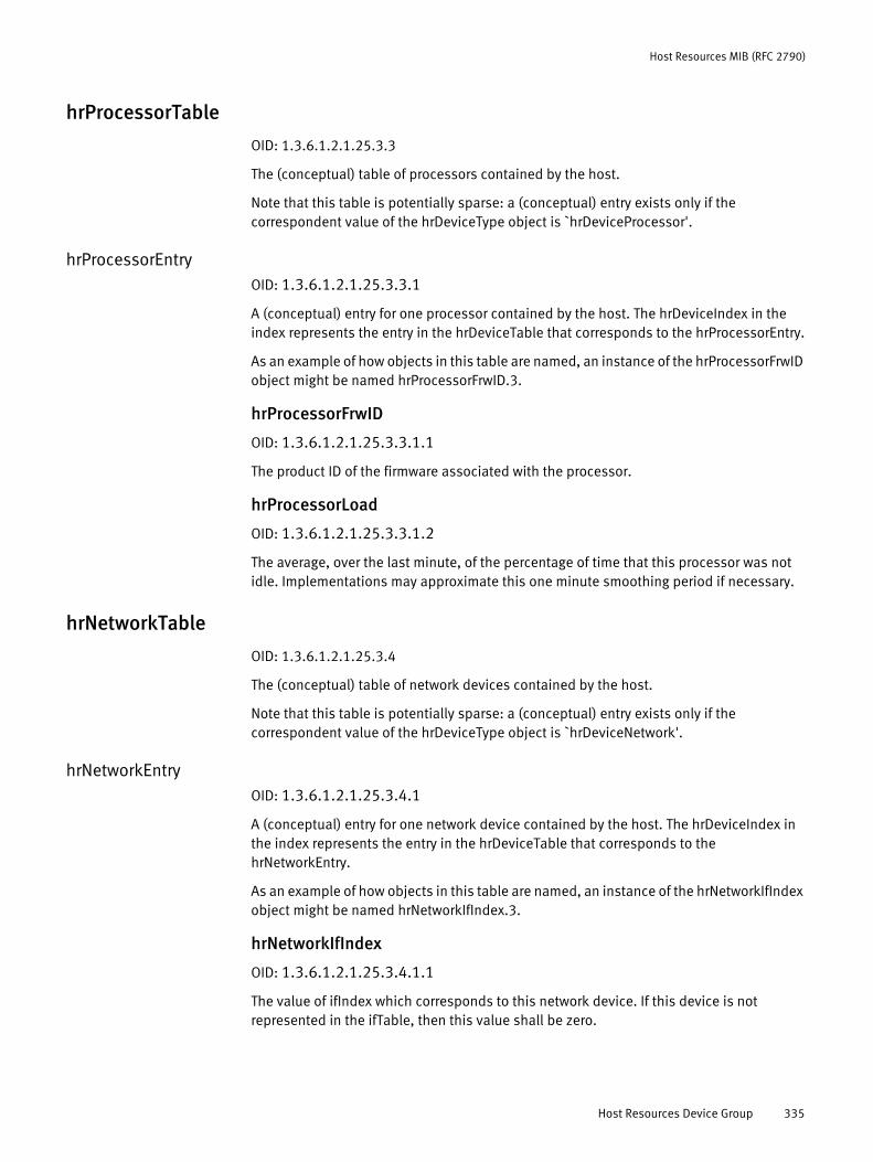
Host Resources MIB (RFC 2790)
hrProcessorTable
OID: 1.3.6.1.2.1.25.3.3
The (conceptual) table of processors contained by the host.
Note that this table is potentially sparse: a (conceptual) entry exists only if the correspondent value of the hrDeviceType object is `hrDeviceProcessor'.
hrProcessorEntryOID: 1.3.6.1.2.1.25.3.3.1
A (conceptual) entry for one processor contained by the host. The hrDeviceIndex in the index represents the entry in the hrDeviceTable that corresponds to the hrProcessorEntry.
As an example of how objects in this table are named, an instance of the hrProcessorFrwID object might be named hrProcessorFrwID.3.
hrProcessorFrwID
OID: 1.3.6.1.2.1.25.3.3.1.1
The product ID of the firmware associated with the processor.
hrProcessorLoad
OID: 1.3.6.1.2.1.25.3.3.1.2
The average, over the last minute, of the percentage of time that this processor was not idle. Implementations may approximate this one minute smoothing period if necessary.
hrNetworkTable
OID: 1.3.6.1.2.1.25.3.4
The (conceptual) table of network devices contained by the host.
Note that this table is potentially sparse: a (conceptual) entry exists only if the correspondent value of the hrDeviceType object is `hrDeviceNetwork'.
hrNetworkEntryOID: 1.3.6.1.2.1.25.3.4.1
A (conceptual) entry for one network device contained by the host. The hrDeviceIndex in the index represents the entry in the hrDeviceTable that corresponds to the hrNetworkEntry.
As an example of how objects in this table are named, an instance of the hrNetworkIfIndex object might be named hrNetworkIfIndex.3.
hrNetworkIfIndex
OID: 1.3.6.1.2.1.25.3.4.1.1
The value of ifIndex which corresponds to this network device. If this device is not represented in the ifTable, then this value shall be zero.
Host Resources Device Group 335
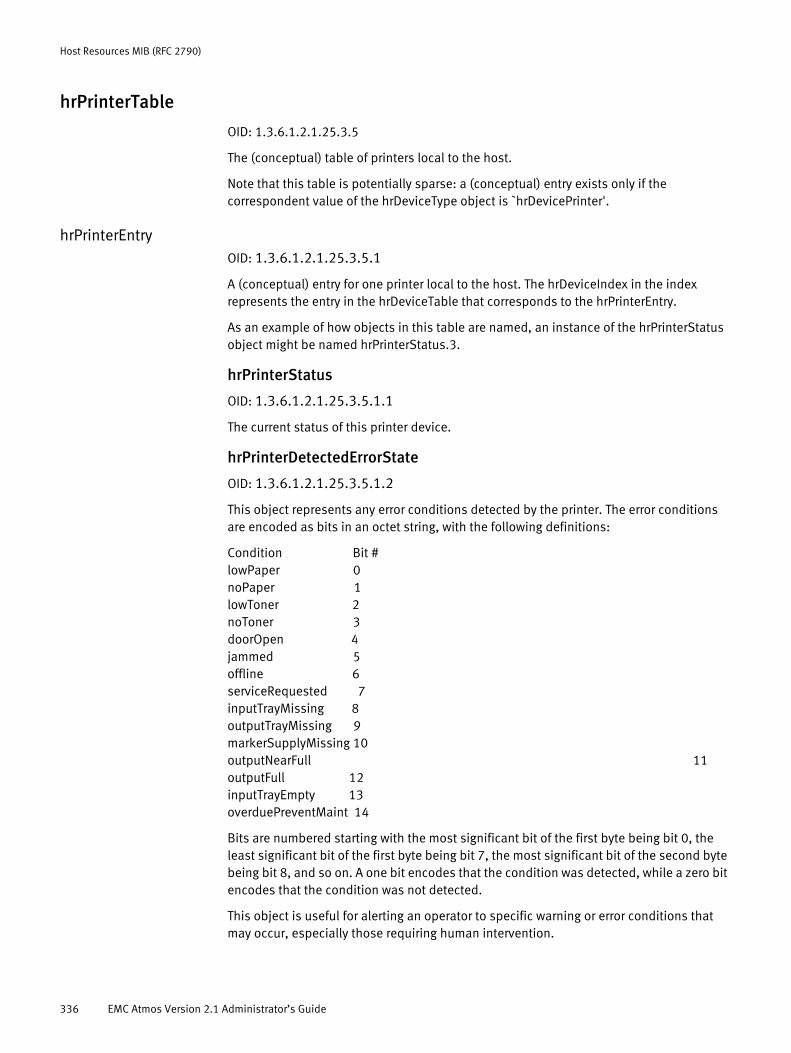
Host Resources MIB (RFC 2790)
hrPrinterTable
OID: 1.3.6.1.2.1.25.3.5
The (conceptual) table of printers local to the host.
Note that this table is potentially sparse: a (conceptual) entry exists only if the correspondent value of the hrDeviceType object is `hrDevicePrinter'.
hrPrinterEntryOID: 1.3.6.1.2.1.25.3.5.1
A (conceptual) entry for one printer local to the host. The hrDeviceIndex in the index represents the entry in the hrDeviceTable that corresponds to the hrPrinterEntry.
As an example of how objects in this table are named, an instance of the hrPrinterStatus object might be named hrPrinterStatus.3.
hrPrinterStatus
OID: 1.3.6.1.2.1.25.3.5.1.1
The current status of this printer device.
hrPrinterDetectedErrorState
OID: 1.3.6.1.2.1.25.3.5.1.2
This object represents any error conditions detected by the printer. The error conditions are encoded as bits in an octet string, with the following definitions:
Condition Bit #lowPaper 0noPaper 1lowToner 2noToner 3doorOpen 4jammed 5offline 6serviceRequested 7inputTrayMissing 8outputTrayMissing 9markerSupplyMissing 10outputNearFull 11outputFull 12inputTrayEmpty 13overduePreventMaint 14
Bits are numbered starting with the most significant bit of the first byte being bit 0, the least significant bit of the first byte being bit 7, the most significant bit of the second byte being bit 8, and so on. A one bit encodes that the condition was detected, while a zero bit encodes that the condition was not detected.
This object is useful for alerting an operator to specific warning or error conditions that may occur, especially those requiring human intervention.
336 EMC Atmos Version 2.1 Administrator’s Guide
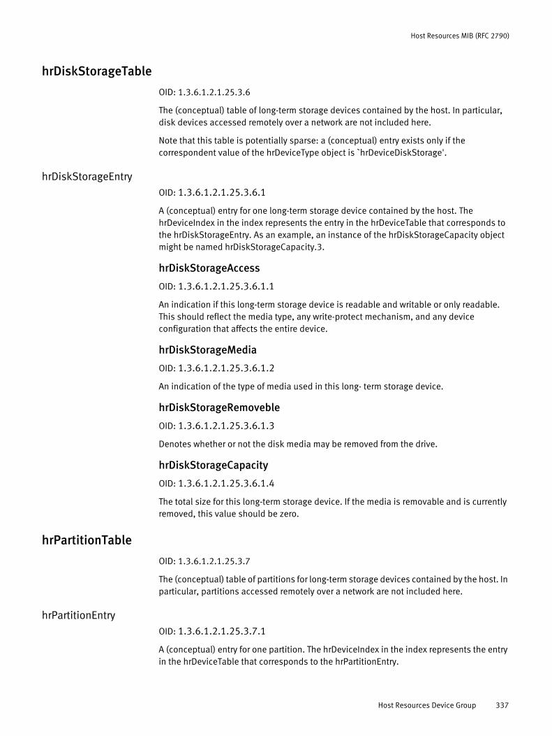
Host Resources MIB (RFC 2790)
hrDiskStorageTable
OID: 1.3.6.1.2.1.25.3.6
The (conceptual) table of long-term storage devices contained by the host. In particular, disk devices accessed remotely over a network are not included here.
Note that this table is potentially sparse: a (conceptual) entry exists only if the correspondent value of the hrDeviceType object is `hrDeviceDiskStorage'.
hrDiskStorageEntryOID: 1.3.6.1.2.1.25.3.6.1
A (conceptual) entry for one long-term storage device contained by the host. The hrDeviceIndex in the index represents the entry in the hrDeviceTable that corresponds to the hrDiskStorageEntry. As an example, an instance of the hrDiskStorageCapacity object might be named hrDiskStorageCapacity.3.
hrDiskStorageAccess
OID: 1.3.6.1.2.1.25.3.6.1.1
An indication if this long-term storage device is readable and writable or only readable. This should reflect the media type, any write-protect mechanism, and any device configuration that affects the entire device.
hrDiskStorageMedia
OID: 1.3.6.1.2.1.25.3.6.1.2
An indication of the type of media used in this long- term storage device.
hrDiskStorageRemoveble
OID: 1.3.6.1.2.1.25.3.6.1.3
Denotes whether or not the disk media may be removed from the drive.
hrDiskStorageCapacity
OID: 1.3.6.1.2.1.25.3.6.1.4
The total size for this long-term storage device. If the media is removable and is currently removed, this value should be zero.
hrPartitionTable
OID: 1.3.6.1.2.1.25.3.7
The (conceptual) table of partitions for long-term storage devices contained by the host. In particular, partitions accessed remotely over a network are not included here.
hrPartitionEntryOID: 1.3.6.1.2.1.25.3.7.1
A (conceptual) entry for one partition. The hrDeviceIndex in the index represents the entry in the hrDeviceTable that corresponds to the hrPartitionEntry.
Host Resources Device Group 337
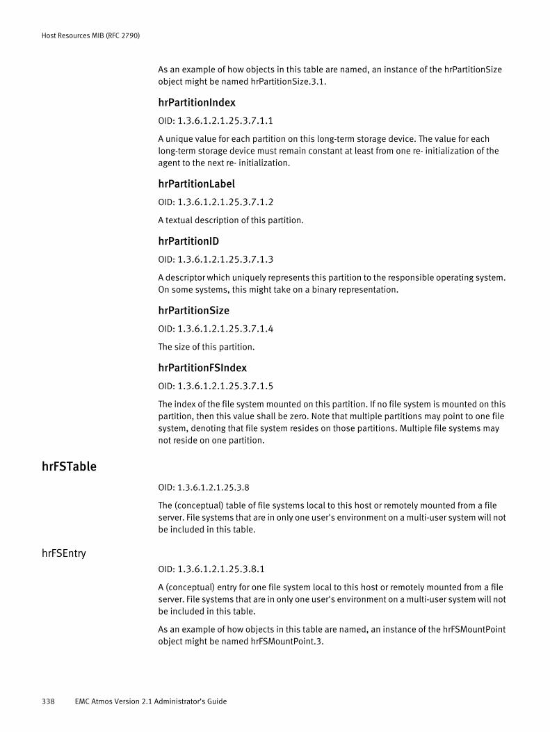
Host Resources MIB (RFC 2790)
As an example of how objects in this table are named, an instance of the hrPartitionSize object might be named hrPartitionSize.3.1.
hrPartitionIndex
OID: 1.3.6.1.2.1.25.3.7.1.1
A unique value for each partition on this long-term storage device. The value for each long-term storage device must remain constant at least from one re- initialization of the agent to the next re- initialization.
hrPartitionLabel
OID: 1.3.6.1.2.1.25.3.7.1.2
A textual description of this partition.
hrPartitionID
OID: 1.3.6.1.2.1.25.3.7.1.3
A descriptor which uniquely represents this partition to the responsible operating system. On some systems, this might take on a binary representation.
hrPartitionSize
OID: 1.3.6.1.2.1.25.3.7.1.4
The size of this partition.
hrPartitionFSIndex
OID: 1.3.6.1.2.1.25.3.7.1.5
The index of the file system mounted on this partition. If no file system is mounted on this partition, then this value shall be zero. Note that multiple partitions may point to one file system, denoting that file system resides on those partitions. Multiple file systems may not reside on one partition.
hrFSTable
OID: 1.3.6.1.2.1.25.3.8
The (conceptual) table of file systems local to this host or remotely mounted from a file server. File systems that are in only one user's environment on a multi-user system will not be included in this table.
hrFSEntryOID: 1.3.6.1.2.1.25.3.8.1
A (conceptual) entry for one file system local to this host or remotely mounted from a file server. File systems that are in only one user's environment on a multi-user system will not be included in this table.
As an example of how objects in this table are named, an instance of the hrFSMountPoint object might be named hrFSMountPoint.3.
338 EMC Atmos Version 2.1 Administrator’s Guide
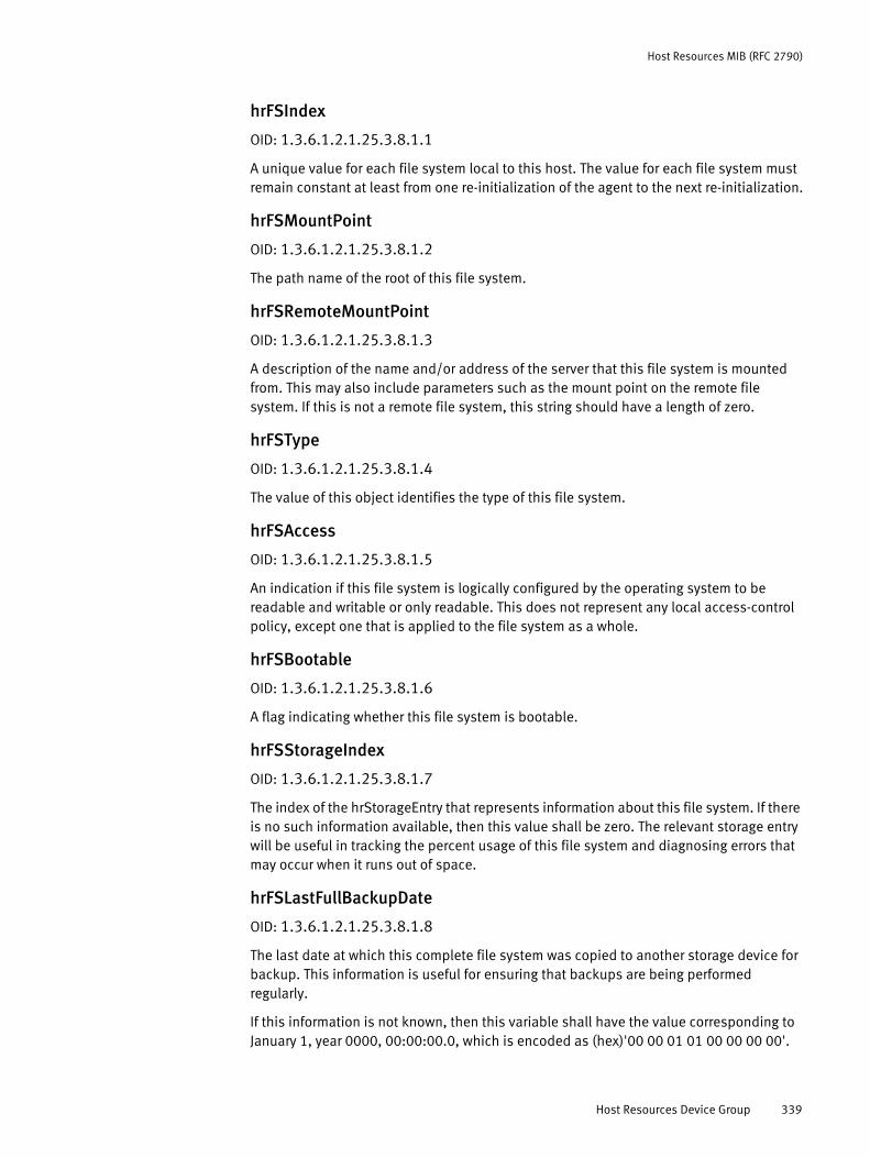
Host Resources MIB (RFC 2790)
hrFSIndex
OID: 1.3.6.1.2.1.25.3.8.1.1
A unique value for each file system local to this host. The value for each file system must remain constant at least from one re-initialization of the agent to the next re-initialization.
hrFSMountPoint
OID: 1.3.6.1.2.1.25.3.8.1.2
The path name of the root of this file system.
hrFSRemoteMountPoint
OID: 1.3.6.1.2.1.25.3.8.1.3
A description of the name and/or address of the server that this file system is mounted from. This may also include parameters such as the mount point on the remote file system. If this is not a remote file system, this string should have a length of zero.
hrFSType
OID: 1.3.6.1.2.1.25.3.8.1.4
The value of this object identifies the type of this file system.
hrFSAccess
OID: 1.3.6.1.2.1.25.3.8.1.5
An indication if this file system is logically configured by the operating system to be readable and writable or only readable. This does not represent any local access-control policy, except one that is applied to the file system as a whole.
hrFSBootable
OID: 1.3.6.1.2.1.25.3.8.1.6
A flag indicating whether this file system is bootable.
hrFSStorageIndex
OID: 1.3.6.1.2.1.25.3.8.1.7
The index of the hrStorageEntry that represents information about this file system. If there is no such information available, then this value shall be zero. The relevant storage entry will be useful in tracking the percent usage of this file system and diagnosing errors that may occur when it runs out of space.
hrFSLastFullBackupDate
OID: 1.3.6.1.2.1.25.3.8.1.8
The last date at which this complete file system was copied to another storage device for backup. This information is useful for ensuring that backups are being performed regularly.
If this information is not known, then this variable shall have the value corresponding to January 1, year 0000, 00:00:00.0, which is encoded as (hex)'00 00 01 01 00 00 00 00'.
Host Resources Device Group 339

Host Resources MIB (RFC 2790)
hrFSLastPartialBackupDate
OID: 1.3.6.1.2.1.25.3.8.1.9
The last date at which a portion of this file system was copied to another storage device for backup. This information is useful for ensuring that backups are being performed regularly.
If this information is not known, then this variable shall have the value corresponding to January 1, year 0000, 00:00:00.0, which is encoded as (hex)'00 00 01 01 00 00 00 00'.
hrFSTypes
OID: 1.3.6.1.2.1.25.3.9
Registrations for some popular File System types, for use with hrFSType.
hrFSOtherOID: 1.3.6.1.2.1.25.3.9.1
The file system type identifier used when no other defined type is appropriate.
hrFSUnknownOID: 1.3.6.1.2.1.25.3.9.2
The file system type identifier used when the type of file system is unknown.
hrFSBerkeleyFFSOID: 1.3.6.1.2.1.25.3.9.3
The file system type identifier used for the Berkeley Fast File System.
hrFSSys5FSOID: 1.3.6.1.2.1.25.3.9.4
The file system type identifier used for the System V File System.
hrFSFatOID: 1.3.6.1.2.1.25.3.9.5
The file system type identifier used for DOS's FAT file system.
hrFSHPFSOID: 1.3.6.1.2.1.25.3.9.6
The file system type identifier used for OS/2's High Performance File System.
hrFSHFSOID: 1.3.6.1.2.1.25.3.9.7
The file system type identifier used for the Macintosh Hierarchical File System.
hrFSMFSOID: 1.3.6.1.2.1.25.3.9.8
340 EMC Atmos Version 2.1 Administrator’s Guide

Host Resources MIB (RFC 2790)
The file system type identifier used for the Macintosh File System.
hrFSNTFSOID: 1.3.6.1.2.1.25.3.9.9
The file system type identifier used for the Windows NT File System.
hrFSVNodeOID: 1.3.6.1.2.1.25.3.9.10
The file system type identifier used for the VNode File System.
hrFSJournaledOID: 1.3.6.1.2.1.25.3.9.11
The file system type identifier used for the Journaled File System.
hrFSiso9660OID: 1.3.6.1.2.1.25.3.9.12
The file system type identifier used for the ISO 9660 File System for CD's.
hrFSRockRidgeOID: 1.3.6.1.2.1.25.3.9.13
The file system type identifier used for the RockRidge File System for CD's.
hrFSNFSOID: 1.3.6.1.2.1.25.3.9.14
The file system type identifier used for the NFS File System.
hrFSNetwareOID: 1.3.6.1.2.1.25.3.9.15
The file system type identifier used for the Netware File System.
hrFSAFSOID: 1.3.6.1.2.1.25.3.9.16
The file system type identifier used for the Andrew File System.
hrFSDFSOID: 1.3.6.1.2.1.25.3.9.17
The file system type identifier used for the OSF DCE Distributed File System.
hrFSAppleshareOID: 1.3.6.1.2.1.25.3.9.18
The file system type identifier used for the AppleShare File System.
Host Resources Device Group 341

Host Resources MIB (RFC 2790)
hrFSRFSOID: 1.3.6.1.2.1.25.3.9.19
The file system type identifier used for the RFS File System.
hrFSDGCFSOID: 1.3.6.1.2.1.25.3.9.20
The file system type identifier used for the Data General DGCFS.
hrFSBFSOID: 1.3.6.1.2.1.25.3.9.21
The file system type identifier used for the SVR4 Boot File System.
hrFSFAT32OID: 1.3.6.1.2.1.25.3.9.22
The file system type identifier used for the Windows FAT32 File System.
hrFSLinuxExt2OID: 1.3.6.1.2.1.25.3.9.23
The file system type identifier used for the Linux EXT2 File System.
Host Resources Running Software GroupThe hrSWRunTable contains an entry for each distinct piece of software that is running or loaded into physical or virtual memory in preparation for running. This includes the host's operating system, device drivers, and applications.
hrSWOSIndex
OID: 1.3.6.1.2.1.25.4.1
The value of the hrSWRunIndex for the hrSWRunEntry that represents the primary operating system running on this host. This object is useful for quickly and uniquely identifying that primary operating system.
hrSWRunTable
OID: 1.3.6.1.2.1.25.4.2
The (conceptual) table of software running on the host.
hrSWRunEntryOID: 1.3.6.1.2.1.25.4.2.1
A (conceptual) entry for one piece of software running on the host. Note that because the installed software table only contains information for software stored locally on this host, not every piece of running software will be found in the installed software table. This is true of software that was loaded and run from a non-local source, such as a network-mounted file system.
342 EMC Atmos Version 2.1 Administrator’s Guide
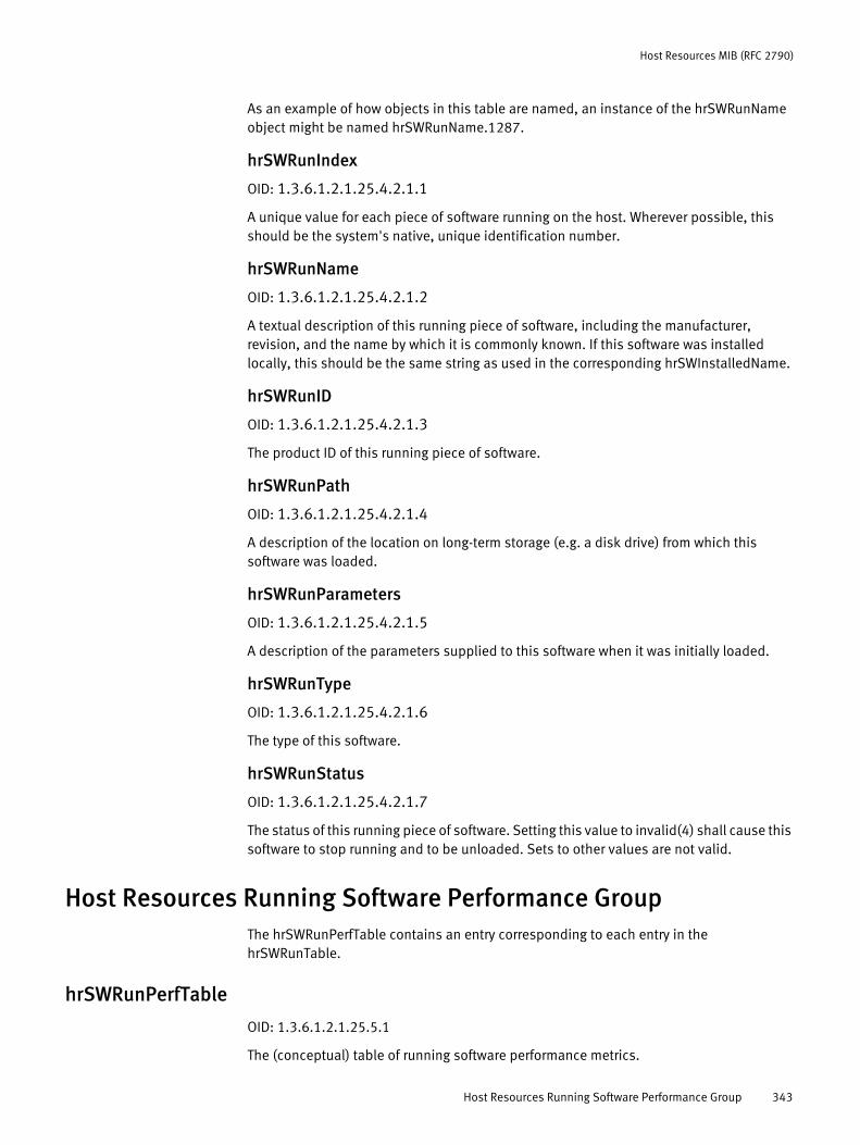
Host Resources MIB (RFC 2790)
As an example of how objects in this table are named, an instance of the hrSWRunName object might be named hrSWRunName.1287.
hrSWRunIndex
OID: 1.3.6.1.2.1.25.4.2.1.1
A unique value for each piece of software running on the host. Wherever possible, this should be the system's native, unique identification number.
hrSWRunName
OID: 1.3.6.1.2.1.25.4.2.1.2
A textual description of this running piece of software, including the manufacturer, revision, and the name by which it is commonly known. If this software was installed locally, this should be the same string as used in the corresponding hrSWInstalledName.
hrSWRunID
OID: 1.3.6.1.2.1.25.4.2.1.3
The product ID of this running piece of software.
hrSWRunPath
OID: 1.3.6.1.2.1.25.4.2.1.4
A description of the location on long-term storage (e.g. a disk drive) from which this software was loaded.
hrSWRunParameters
OID: 1.3.6.1.2.1.25.4.2.1.5
A description of the parameters supplied to this software when it was initially loaded.
hrSWRunType
OID: 1.3.6.1.2.1.25.4.2.1.6
The type of this software.
hrSWRunStatus
OID: 1.3.6.1.2.1.25.4.2.1.7
The status of this running piece of software. Setting this value to invalid(4) shall cause this software to stop running and to be unloaded. Sets to other values are not valid.
Host Resources Running Software Performance GroupThe hrSWRunPerfTable contains an entry corresponding to each entry in the hrSWRunTable.
hrSWRunPerfTable
OID: 1.3.6.1.2.1.25.5.1
The (conceptual) table of running software performance metrics.
Host Resources Running Software Performance Group 343
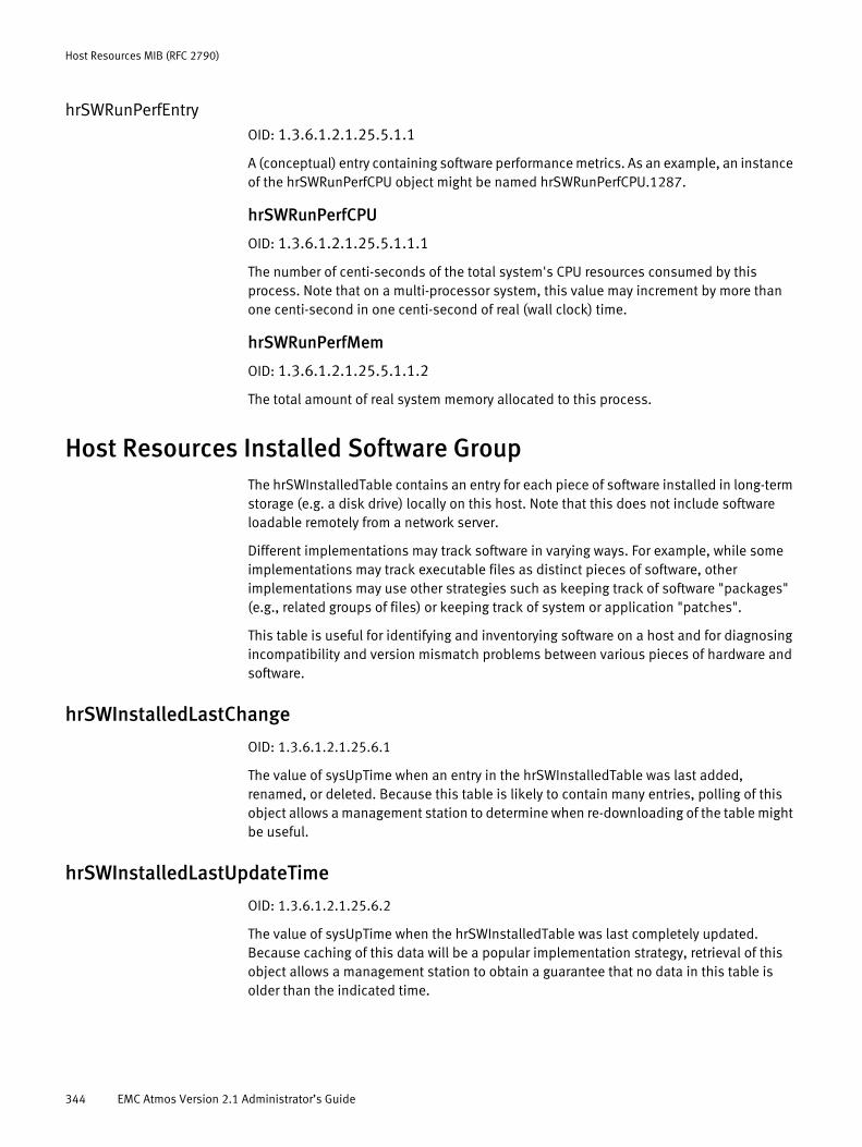
Host Resources MIB (RFC 2790)
hrSWRunPerfEntryOID: 1.3.6.1.2.1.25.5.1.1
A (conceptual) entry containing software performance metrics. As an example, an instance of the hrSWRunPerfCPU object might be named hrSWRunPerfCPU.1287.
hrSWRunPerfCPU
OID: 1.3.6.1.2.1.25.5.1.1.1
The number of centi-seconds of the total system's CPU resources consumed by this process. Note that on a multi-processor system, this value may increment by more than one centi-second in one centi-second of real (wall clock) time.
hrSWRunPerfMem
OID: 1.3.6.1.2.1.25.5.1.1.2
The total amount of real system memory allocated to this process.
Host Resources Installed Software GroupThe hrSWInstalledTable contains an entry for each piece of software installed in long-term storage (e.g. a disk drive) locally on this host. Note that this does not include software loadable remotely from a network server.
Different implementations may track software in varying ways. For example, while some implementations may track executable files as distinct pieces of software, other implementations may use other strategies such as keeping track of software "packages" (e.g., related groups of files) or keeping track of system or application "patches".
This table is useful for identifying and inventorying software on a host and for diagnosing incompatibility and version mismatch problems between various pieces of hardware and software.
hrSWInstalledLastChange
OID: 1.3.6.1.2.1.25.6.1
The value of sysUpTime when an entry in the hrSWInstalledTable was last added, renamed, or deleted. Because this table is likely to contain many entries, polling of this object allows a management station to determine when re-downloading of the table might be useful.
hrSWInstalledLastUpdateTime
OID: 1.3.6.1.2.1.25.6.2
The value of sysUpTime when the hrSWInstalledTable was last completely updated. Because caching of this data will be a popular implementation strategy, retrieval of this object allows a management station to obtain a guarantee that no data in this table is older than the indicated time.
344 EMC Atmos Version 2.1 Administrator’s Guide
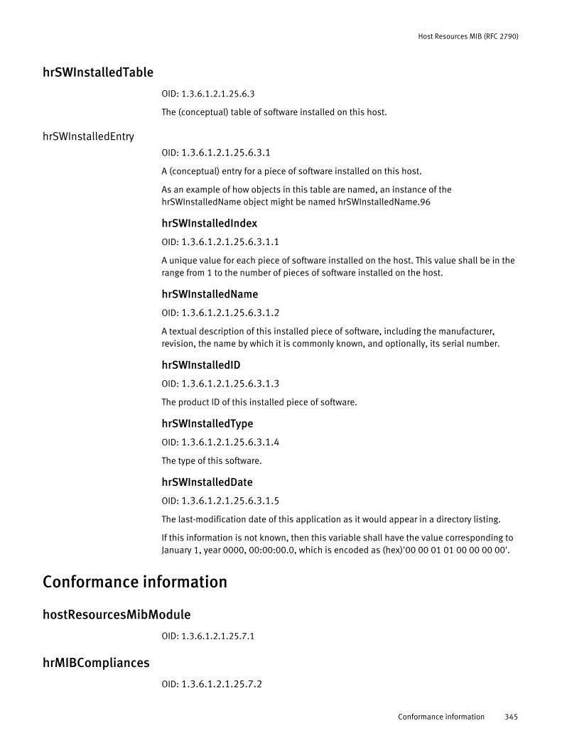
Host Resources MIB (RFC 2790)
hrSWInstalledTable
OID: 1.3.6.1.2.1.25.6.3
The (conceptual) table of software installed on this host.
hrSWInstalledEntryOID: 1.3.6.1.2.1.25.6.3.1
A (conceptual) entry for a piece of software installed on this host.
As an example of how objects in this table are named, an instance of the hrSWInstalledName object might be named hrSWInstalledName.96
hrSWInstalledIndex
OID: 1.3.6.1.2.1.25.6.3.1.1
A unique value for each piece of software installed on the host. This value shall be in the range from 1 to the number of pieces of software installed on the host.
hrSWInstalledName
OID: 1.3.6.1.2.1.25.6.3.1.2
A textual description of this installed piece of software, including the manufacturer, revision, the name by which it is commonly known, and optionally, its serial number.
hrSWInstalledID
OID: 1.3.6.1.2.1.25.6.3.1.3
The product ID of this installed piece of software.
hrSWInstalledType
OID: 1.3.6.1.2.1.25.6.3.1.4
The type of this software.
hrSWInstalledDate
OID: 1.3.6.1.2.1.25.6.3.1.5
The last-modification date of this application as it would appear in a directory listing.
If this information is not known, then this variable shall have the value corresponding to January 1, year 0000, 00:00:00.0, which is encoded as (hex)'00 00 01 01 00 00 00 00'.
Conformance information
hostResourcesMibModule
OID: 1.3.6.1.2.1.25.7.1
hrMIBCompliances
OID: 1.3.6.1.2.1.25.7.2
Conformance information 345

Host Resources MIB (RFC 2790)
hrMIBComplianceOID: 1.3.6.1.2.1.25.7.2.1
hrMIBGroups
OID: 1.3.6.1.2.1.25.7.3
hrSystemGroupOID: 1.3.6.1.2.1.25.7.3.1
The Host Resources System Group.
hrStorageGroupOID: 1.3.6.1.2.1.25.7.3.2
The Host Resources Storage Group.
hrDeviceGroupOID: 1.3.6.1.2.1.25.7.3.3
The Host Resources Device Group.
hrSWRunGroupOID: 1.3.6.1.2.1.25.7.3.4
The Host Resources Running Software Group.
hrSWRunPerfGroupOID: 1.3.6.1.2.1.25.7.3.5
The Host Resources Running Software Performance Group.
hrSWInstalledGroupOID: 1.3.6.1.2.1.25.7.3.6
The Host Resources Installed Software Group.
346 EMC Atmos Version 2.1 Administrator’s Guide

GLOSSARY
This glossary contains terms related to the Atmos system. Many of these terms are used in this manual.
A
access node An internal Atmos node that acts as an entry point for requests generated by clients who do not reside within the Atmos system. An access node can be assigned to one tenant.
Atmos API Atmos provides an API for object access and management (REST and SOAP), and for system management tasks.
Atmos CAS API Atmos provides an access method for Content Addressed Storage on the Atmos platform.
Atmos Installable FileSystem
Atmos software packaged as an rpm and installed on a Linux system running FUSE. IFS enables access to the Atmos storage cloud from traditional file system applications.
Atmos services Atmos services include client service (CS), job service (JS), metadata location service (MDLS), metadata service (MDS), resource management service (RMS), storage service (SS), web service (WS). All Atmos services (except the MDLS) run on every node in the system. The MDLS runs on first two nodes of first RMG, and the first node of subsequent RMGs.
Atmos Virtual Edition The Atmos software that can be installed in a virtual environment.
C
C-Clip A package containing the user’s data and associated metadata. When a user presents a file to the Atmos CAS system, the system calculates a unique Content Address (CA) for the data and then stores the file. The system also creates a separate XML file containing the CA of the user’s file and application-specific metadata. Both the XML file and the user’s data are stored in the C-Clip.
C-Clip Descriptor File(CDF)
The additional XML file that the system creates when making a C-Clip. This file includes the Content Addresses for all referenced blobs and associated metadata.
client service CS. An Atmos service that manages requests that come in via Web Service, IFS, and CIFS/NFS. The client service is installed on every Atmos node.
consistency checker CC. An Atmos service that runs for each tenant. It checks all objects of the tenant and initiates recovery if it fails to access a replica or determines that a replica is not consistent. It runs at a low priority in the background.
Content AddressedStorage (CAS)
The generic term for an Atmos CAS node and its software.
EMC Atmos Version 2.1 Administrator’s Guide 347
Glossary
D
default policy The policy that the Atmos policy manager applies when no other policy is assigned by the user, or no other policy matches. The default policy is named default and defines two synchronous replicas without location or server attribute constraints.
deletion period A policy specification that defines a time period after which Atmos automatically deletes an object.
E
GeoParity An Atmos feature that provides data redundancy without the overhead of replication.
exceptional objects An Atmos object that is known or suspected to be out of conformance with its placement policy specification due to the failure of one or more of its replicas. When Atmos discovers a replica that might be in an invalid state, it records the object on a list of exceptional objects. These exceptional objects are automatically checked for consistency once a day, by default.
F
federation An Atmos replica definition. When defining policies, replicas can be federated. Federated replicas are distributed across a combination of internal Atmos systems and external Atmos-based systems. Atmos supports access to federated data via file-system and Web-services access mechanisms.
file-system client File-system access is provided via NFS (Network File System), CIFS (Common Internet File System), or installable file systems for specific operating systems.
FUSE File System in User Space. Software required by the Atmos installable file system.
G
GeoProtect An Atmos feature that provides better protection optimized for the cloud. GeoProtect increases the availability of your content, reduces storage overhead, and improves access to content.
I
initial master node The first node of the first installation segment in the first RMG that is installed in the system becomes the initial master node. Each Atmos system has only one initial master node. You use the IP address of this node to initiate the system.
installation segment A set of nodes that share the same “private,” management subnet.
J
job service JS. The Atmos service responsible for all asynchronous data-maintenance tasks, like asynchronous replication and consistency checking. It runs on most Atmos nodes and is an application that sits on top of the client.
348 EMC Atmos Version 2.1 Administrator’s Guide
Glossary
L
location Identifies the physical location of the RMG. The RMG’s location is specified during system installation.
location group A collection of two or more locations that is designed to provide enhanced replica placement options when an Atmos deployment has three or more locations
M
management network The private network (eth0) that handles internal management and installation. It is assigned a private IP address.
master node The first node installed in each installation segment. It always has -001 appended to its node name. When a new RMG is added to the system, it has one installation segment, hence one master node. If more installation segments are added to that RMG later, there are more master nodes: an RMG with N installation segments has N master nodes. The very first master node in an Atmos system is the initial master node.
mauicc The Atmos service that performs consistency checking.
mauifs The Atmos service that runs on the Atmos installable file system.
mauiverify A command-line tool used to check the Atmos system’s status. It is typically used to verify that there are no issues that will prevent a successful upgrade. It reports system alerts, and the status of Atmos services and nodes.
metadata disk ratio A setting applied by the user when installing Atmos. It defines the amount of disks to use for metadata storage and the amount to use for data storage. The ratio selected depends on what kind of data the system is expected to handle.
metadata service MDS. The Atmos service that maintains the physical location and layout of objects. Responsible for a range of object identifiers (OIDs) and their metadata. It tells the client service where to store a piece of metadata. Installed on every node.
metadata locationservice
MDLS. The Atmos service that maintains the location of MDS objects. An index responsible for tracking the metadata database locations, and the MDS that owns it. It is installed on the first two nodes of a system, and on the master node of every subsequent RMG.
metadata One of two components of an object, along with user data. Metadata is divided into system metadata and user metadata.
N
namespace Data access provided by a file-system client occurs in the context of a namespace.
namespace interface Atmos web services support an object interface and a namespace interface for interacting with objects. The namespace interface allows an application to interact with objects using file and directory paths.
EMC Atmos Version 2.1 Administrator’s Guide 349
Glossary
node A device where Atmos software is installed and that runs the set of Atmos services that store, retrieve, categorize, and manage the data in the system. Nodes are either master or slave.
network time protocol The protocol used to synchronize the computer clock with a network time source. Atmos requires that time be synchronized across all nodes and clients within 5 minutes. It is recommended that an external NTP server be used for this purpose.
O
object interface Atmos web services support an object interface and a namespace interface for interacting with objects. The object interface allows an application to interact with objects using the object identifier.
P
policy manager service PM. An Atmos service that stores policies and selects the appropriate policies for objects.
policy A set of rules used to guide Atmos about how, when, and where to replicate, and store objects. It is a combination of a policy selector and a policy specification.
policy selector The conditions under which a policy is triggered. If you view a policy as an if-then statement: the selector is the “if” clause.
policy specification A description of what happens when a policy is selected for use, such as information about replicas, striping, and server attributes. If you view a policy as an if-then statement: the specification is the “then” clause.
policy specificationtransition
An information lifecycle storage strategy for an object. It describes how an object should transition among a set of policy specifications for a set of age-based conditions.
private network The Atmos network interface (eth0) used for internal management traffic, such as Installing Atmos (PXE, DHCP, and IPMI), intra-node communications (within an IS), upgrading to a new Atmos version, and replacing nodes.
public network The Atmos network interface (eth1 and above) used for data, replication and system management traffic. This interface is assigned an externally facing IP addresses.
R
resource managementgroup
RMG. A collection of installation segments that share a single domain. In almost all cases, this is equivalent to a subnet on the “public,” customer network. You can create multiple RMGs on the same subnet, as long as each RMG has a unique address. RMGs are responsible for monitoring and discovering nodes within the subnet.
resource managerservice
RMS. The Atmos service that tracks the availability, status, and location of storage services, and the specific features available with those storage services (for example, compression).
retention An Atmos service that can be applied via policy to data-at-rest. If enabled, it defines a time period during which an object cannot be modified. Objects that have a retention period enabled cannot be modified or deleted. Once the retention period expires, the object can be modified or deleted.
350 EMC Atmos Version 2.1 Administrator’s Guide
Glossary
rolling upgrade The upgrade process where Atmos remains accessible and responsive while the software is upgraded.
S
SS Storage Server. A physical server on which user data is stored.
subtenant A logical subset of a tenant that groups together selected policies, data access (that is, file-system or Web-service namespaces), and reporting capabilities. When the SysAdmin creates a tenant, the system automatically creates one corresponding subtenant (which is identical to the tenant). SysAdmins can choose to create additional subtenants within each tenant.
System AdministrationConsole
The application used to configure, manage, and monitor the Atmos system.
system metadata Atmos objects include the following system metadata: atime—last access time, mtime—last modified time, ctime—change time, itime—create time, uid— UID from UID List, where you create new applications from, gid—group ID, N/A to Web Service users; ignore, size—object size in bytes.
T
tenant A conceptual subset of the storage resources within an Atmos system. Associated with a tenant are specific storage resources, security control, storage policies, and access to the data stored on that tenant's resources. Each tenant has a name that is unique system-wide.
Tenant Admin A role within a specific tenant, assigned to one or more users. TenantAdmins control the storage resources, security and storage policies, and data usage of the tenant to which they are assigned. A given user can be a TenantAdmin for multiple tenants. TenantAdmins are unaware of system resources other than those defined for their tenant, nor any ability to access those resources.
U
user data Atmos objects are comprised of user data and metadata.
user meta data Metadata assigned to an object by the user. It is arbitrary key/value pairs. Examples of user metadata are artist name (for example, for MP3 data) and customer type.
W
web services client A flexible Web-services client interface allows direct access to the object API over SOAP or REST. This enables customers to implement a solution without needing to understand the underlying implementation. Using the Atmos Web-services interface allows customers to quickly integrate Atmos with existing applications that, like Atmos, have a service-oriented architecture.
EMC Atmos Version 2.1 Administrator’s Guide 351

Glossary
352 EMC Atmos Version 2.1 Administrator’s Guide

INDEX
Numerics10892.mib 118
Aaccess nodes 176, 229Active Directory 104, 169address translation group 300alerts 53, 116Atmos CAS 20, 28, 104, 158, 159Atmos CAS API 26Atmos file system 104Atmos-CAS PEA File Generator 179, 180authentication
adding and deleting users 30external 30, 35, 100failover 30internal 30, 35, 100servers 30source 36, 37, 39
BBALANCED object storage 199
CCAS API 22, 25CAS application query 181CAS application registration 181CAS metadata tags 207
_CSO_APPNAME 183, 207_CSO_APPVERSION 183, 207_CSO_ISCDF 207_CSO_ORPHANED_BLOB 207
Certificate Authority 81, 107certificates 81checksum 199CIFS 104Cloud Federations 86community name 118compression 199CompressionDedup 199
Ddashboard
subtenant 156, 227system 47
data transformations 199dcstorag.mib 118deduplication 199deletion period 202Dell OpenManage 118
EEGP group 318email
configuring alerts for an RMG 116OpenManage hardware traps 118SysAdmin 36
EMC online support website 15external authentication 30, 35, 100
Ffailover, authentication 30federation 85, 86, 202file system 104
GGeoProtect 348GREEN object storage 199
HHTTP daemon 148
IICMP group 311initial master node 52installation segment 52interfaces group 294interfaces table 294internal authentication 30, 35, 100IP group 301
LLockBox 92logs
collect system log 57collecting logs 138disk space consumption 138log package 139
Mmaster node 52MDS remote replication 86metadata
location 195system 204user 204
MIB access 117MIB-II object hierarchy 292MIB-II overview 292
EMC Atmos Version 2.1 Administrator’s Guide 353
Index
Nnamespace 90, 162network management station 118NFS 104nodes
Node List 56restarting 57tenants 104
notifications 118NTP server 176, 229
Oobject storage
BALANCED 199GREEN 199OPTIMAL 199
objects and types imported 293ON_CREATE 206ON_SMD_UPDATE 206ON_UMD_UPDATE 206OpenLDAP 92
PPEA file 154, 159, 179performance data 147PKCS12 108PKCS7 108placement strategies 199policy
CAS metadata tags 207defining policy selector 204definition 192deletion period 202federate 202match operators 205reordering 187, 234retention period 202selector 192specification 192striping 200triggers 206XQuery expressions 206
public-key certificate 108
Rremote replication (MDS) 86reports 137REST interface 81, 107restarting nodes 57retention period 202RMG
definition 52new 52
rolesSecurityAdmin 29SubtenantAdmin 29SysAdmin 29TenantAdmin 29
SSamba 169, 232Secure Sockets Layer 81SecurityAdmin
login credentials 46login page 46password 41
segment 52server attributes 198Shared Secret 98, 169, 229shutdown command 57SMTP 116SNMP
agent 117community name 118configure for RMG 118configure system-wide 118daemon 116, 119email contact 121standard MIBs 119traps 117, 118
SNMP group 322SOAP interface 81, 107SSL certificates 81, 107statistics 148striping 200SubtenantAdmin 30
email address 165password 165
subtenantsauthentication source 162dashboard 156, 227definition 30list 163namespace 162renaming 163root directory 162SubtenantAdmin role 164
SYR, see system reporting 114, 128, 130SysAdmin 29, 46
deleting a TenantAdmin 103login credentials 46login page 46password 34, 46, 59
system dashboard 47system group 293system log 57system reporting
configuring 128database 114, 128, 130reports 137
TTCP connection table 316TCP group 314TenantAdmin
creating a SubtenantAdmin 164deleting a SubtenantAdmin 166email address 102
354 EMC Atmos Version 2.1 Administrator’s Guide

IndexIndex
password 102role 30, 154
tenantsauthentication source 91creating 92default subtenant 163LDAP configuration 94list 90namespace 90nodes 104renaming 99root directory 90
textual conventions 292transmission group 321traps
Dell OpenManage 118overview 118
UUDP group 317UID 168, 228
XXQuery expressions 206
EMC Atmos Version 2.1 Administrator’s Guide 355

Index
356 EMC Atmos Version 2.1 Administrator’s Guide