Embed Size (px)
Citation preview

ATMPETE 689 UBDATM
ATM ATM
Lesson 12
Well Engineering

Harold Vance Department of Petroleum Engineering
ATMPETE 689 UBDATM
ATM ATM
Well Engineering
• Circulation Programs
• Circulation Calculations (air, gas, mist)
• Circulation Calculations (gasified liquids)

Harold Vance Department of Petroleum Engineering
ATMPETE 689 UBDATM
ATM ATM
Well Engineering
• Wellhead Design
• Casing Design
• Completion Design

Harold Vance Department of Petroleum Engineering
ATMPETE 689 UBDATM
ATM ATM
Well Engineering
• Bit selection
• Underbalanced perforating
• Drillstring design
• Separator design

Harold Vance Department of Petroleum Engineering
ATMPETE 689 UBDATM
ATM ATM
Hole Cleaning
• Optimizing hydraulics with gasses is primarily concerned with hole cleaning - getting the cuttings that are generated by the bit out of the hole.
• With gas, rheological properties have very little to do with hole cleaning
• Hole cleaning with gasses is almost entirely dependent on the annular velocity

Harold Vance Department of Petroleum Engineering
ATMPETE 689 UBDATM
ATM ATM
Drag and Gravitational Forces
• Flowing air exerts a drag force on cuttings
• Gravitational force on the cuttings
• Therefore there is a threshold velocity in which the cuttings will be lifted from the wellbore.
• Threshold velocity increases with size of cuttings.

Harold Vance Department of Petroleum Engineering
ATMPETE 689 UBDATM
ATM ATM
Hole cleaning
• Compressibility of air (or gas) complicates matters.
• Frictional pressure increases downhole pressure - decreases velocity downhole
• Suspended cuttings increase the density of the air, increasing downhole pressure.
• Temperature has an effect on volumetric flow rate.

Harold Vance Department of Petroleum Engineering
ATMPETE 689 UBDATM
ATM ATM
Hole Cleaning
• We must pump at a velocity high enough to remove the cuttings, but not too high where we waste energy.

Harold Vance Department of Petroleum Engineering
ATMPETE 689 UBDATM
ATM ATM
Hole Cleaning Criteria
• Terminal Velocity Criteria
• Minimum Energy Criteria
• Minimum BHP Criteria

Harold Vance Department of Petroleum Engineering
ATMPETE 689 UBDATM
ATM ATM
Terminal Velocity Criteria
• Gray determined that the minimum velocity of the gas must be at least as high as the terminal velocity of the cutting in order to lift the cutting from the wellbore.
• Vc = Vf - Vt

Harold Vance Department of Petroleum Engineering
ATMPETE 689 UBDATM
ATM ATM
Terminal velocity
3f
3c
d
c
2
lbm/ft fluid, ofdensity ρ
lbm/ft cuttings, ofdensity ρ
tcoefficien dragC
ft. diameter, particle sticcharacterid
ft/sec 32.17 on,accelerati nalgravitatio g
34
fd
fcct C
gdV

Harold Vance Department of Petroleum Engineering
ATMPETE 689 UBDATM
ATM ATM
Terminal Velocity
psia and Rin
conditions hole bottomat are P and T
cuttings round-subfor
164.4
cuttingsflat for
369.3
P
TdV
P
TdV
cct
cct

Harold Vance Department of Petroleum Engineering
ATMPETE 689 UBDATM
ATM ATM
Terminal Velocity
• Terminal velocity in air drilling is determined mainly by:– cutting diameter, shape, and density– bottom hole temperature and pressure

Harold Vance Department of Petroleum Engineering
ATMPETE 689 UBDATM
ATM ATM
Terminal Velocity
• As pressure increases Vt decreases.
• As pressure increases Air velocity decreases
• If the mass flow rate of gas remains constant the local air velocity decreases with increasing pressure.
• The air flow rate required to lift the cuttings increases with increasing BHP

Harold Vance Department of Petroleum Engineering
ATMPETE 689 UBDATM
ATM ATM
Friction Pressure
ft diameter, pipeD
ft diameter, holeD
gravity todueon acceleratig
ft/s velocity,mixturev
lbm/cu.ft density, mixtureρ
cuttings andair of
mixture theoffactor friction f
2
p
h
m
m
m
2
ph
mmmm DDg
vf
dL
dP Eq. 2.5
Harold Vance Department of Petroleum Engineering
ATMPETE 689 UBDATM
ATM ATM
Friction Pressure
pipe theof roughness absoluteε
2ln86.014.1
f
1
correct more is Nikuradse that argued Guo
14.0
quationWeymouth
f
a
333.0
m
ph
ph
a
ca
DD
DDf
ff

Harold Vance Department of Petroleum Engineering
ATMPETE 689 UBDATM
ATM ATM
Friction Pressure
• Mixture density is a function of air density, cuttings density, and mass of the cuttings.
• Air density is a function of the pressure
• Mass of the cuttings is a function of:– ROP– Hole cleaning efficiency

Harold Vance Department of Petroleum Engineering
ATMPETE 689 UBDATM
ATM ATM
Friction Pressure
• Pressure drops down the drillstring and through the bit play a part in BHP due to temperature effects.
• Temperature is also effected by:– formation temperature– influx of formation fluid (expansion of gas into the
wellbore)– Mechanical friction– Pressure

Harold Vance Department of Petroleum Engineering
ATMPETE 689 UBDATM
ATM ATM
Required injection rates???
• Relating downhole air velocities to surface injection rates is quite complex.
• We need cuttings shape and size to determine terminal velocity

Harold Vance Department of Petroleum Engineering
ATMPETE 689 UBDATM
ATM ATM
Minimum Energy Criteria
• Probably the most widely used criteria was developed by Angel in 1957.
• Angel assumed that, for efficient cuttings transport downhole, the kinetic energy of the air striking each cutting should be the same as that of air giving efficient cuttings transport at standard pressure and temperature.

Harold Vance Department of Petroleum Engineering
ATMPETE 689 UBDATM
ATM ATM
Minimum Energy Criteria
ft/min pressure, and Temp standard
atvelocity air(orgas)v
lbm/cuft pressure, and tempstandard
at gas)(or air ofdensity ρ
ft/min downhole, velocity gas)(or air v
lbm/cuft rate,injection
downhole required minimum
at the gas)(or air ofdensity ρ2
1
2
1
stp
stp
min
min
22minmin
stpstpvv

Harold Vance Department of Petroleum Engineering
ATMPETE 689 UBDATM
ATM ATM
Minimum Energy Criteria
minmin
stpstpvv

Harold Vance Department of Petroleum Engineering
ATMPETE 689 UBDATM
ATM ATM
Minimum Energy Criteria
• Experience from shallow blast holes, drilled in limestone quarrying operations, indicated that cuttings were transported efficiently if the air velocity equaled or exceeded 3,000 feet per minute.
• This is equivalent to Gray’s terminal velocity for flat cuttings with a diameter of 0.46 in. or sub-rounded particles of 0.26 in.

Harold Vance Department of Petroleum Engineering
ATMPETE 689 UBDATM
ATM ATM
Minimum Energy Criteria
lbm/min air, of rate flow mass
the;given time ain wellin the
pointany past flowingair of massw
lbm/min cuttings,
of rate flow mass the;given time
ain generated cuttings of massw
1
2
a
c
2
a
cam
ph
mmmm
w
w
DDg
vf
dL
dP
Angel computed the downhole air pressure with eq. 2.5

Harold Vance Department of Petroleum Engineering
ATMPETE 689 UBDATM
ATM ATM
Minimum Energy Criteria
depth holeh
GhTre temperatudownholeT
F/100' gradient, mperatureannular teG
F re, temperatusurfaceT
absolute lbf/sq.ft, pressure,air surfaceP
s
s
s
22
22
aG
abT
T
T
aG
abTPP
G
a
s
ssb

Harold Vance Department of Petroleum Engineering
ATMPETE 689 UBDATM
ATM ATM
Minimum Energy Criteria
ft. diameter, drillpipeD
ft. diameter, holeD
101.625b
ft/hr rate,n penetratioROP
scf/m rate, flow gasQ
1)(airgravity specific gasS
3.53
8.28
p
h
222333.1
26-
2
phph
h
DDDD
Q
Q
DROPSQa

Harold Vance Department of Petroleum Engineering
ATMPETE 689 UBDATM
ATM ATM
Minimum Energy Criteria
This was combined with the cuttings transport criterion defined in Eq 2.10 to deduce the minimum air flow rate as a function of hole depth, annular geometry, and penetration rate.
minmin
stpstpvv Eq. 2.10

Harold Vance Department of Petroleum Engineering
ATMPETE 689 UBDATM
ATM ATM
Minimum Energy Criteria
To simplify, the average downhole temperature can be used to calculate BHP.
2222
2222
261.6av
Tahavs
stpph
s bTebTPvDD
QGhTSav
This was solved numerically for the gas injection rate required to give an annular velocity equivalent in cuttings lifting power to air with a velocity of 3000 ft/min.
A series of charts was generated for different geometries and penetration rates

Harold Vance Department of Petroleum Engineering
ATMPETE 689 UBDATM
ATM ATM
Minimum Energy Criteria
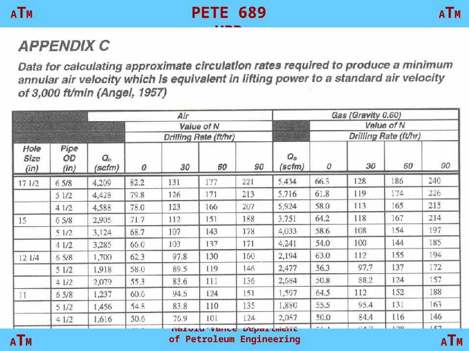
• Qmin can be approximated by:
• Qmin = Qo + NH
• Qo = injection rate (scfm) at zero depth that corresponds to an annular velocity of 3000 ft/min
• N = factor dependent on the penetration rate (Appendix C)
• H = hole depth, 1000 ft.
Harold Vance Department of Petroleum Engineering
ATMPETE 689 UBDATM
ATM ATM

Harold Vance Department of Petroleum Engineering
ATMPETE 689 UBDATM
ATM ATM

Harold Vance Department of Petroleum Engineering
ATMPETE 689 UBDATM
ATM ATM

Harold Vance Department of Petroleum Engineering
ATMPETE 689 UBDATM
ATM ATM
7-7/8” hole 3-1/2” drillpipe
6” drill collars 3800’ hole depth

Harold Vance Department of Petroleum Engineering
ATMPETE 689 UBDATM
ATM ATM
Minimum BHP Criteria
Angel’ analysis does not predict a minimum BHP, but gives a pressure that decreases monotonically with decreasing air flow rate.

Harold Vance Department of Petroleum Engineering
ATMPETE 689 UBDATM
ATM ATM
Natural Gas Drilling
3f
3c
d
c
2
lbm/ft fluid, ofdensity ρ
lbm/ft cuttings, ofdensity ρ
tcoefficien dragC
ft. diameter, particle sticcharacterid
ft/sec 32.17 on,accelerati nalgravitatio g
34
fd
fcct C
gdV

Harold Vance Department of Petroleum Engineering
ATMPETE 689 UBDATM
ATM ATM
Terminal velocity of natural gas
• Vtg = Vtair(1/S)0.5

Harold Vance Department of Petroleum Engineering
ATMPETE 689 UBDATM
ATM ATM
Natural gas drilling
• Lower density of natural gas than air results in:– lower BHP– lower drag forces– Higher required circulation rates– Non-ideal behavior of natural gas is not usually
a problem since operating pressures are low and ideal behavior can be assumed.

Harold Vance Department of Petroleum Engineering
ATMPETE 689 UBDATM
ATM ATM
Natural gas injection rate
• A first order estimate can be derived by taking Angel’s figures for air drilling at the appropriate depth and penetration rate and dividing these by the square root of the gas’s specific gravity.
• Usually acceptable in practice

Harold Vance Department of Petroleum Engineering
ATMPETE 689 UBDATM
ATM ATM
Mist Drilling
• Liquid volumes are only 1 to 2 percent at the prevailing temperature and pressure.
Harold Vance Department of Petroleum Engineering
ATMPETE 689 UBDATM
ATM ATM
Hole cleaning, mist
• Water droplets act similarly to cuttings with slip velocity of near zero - mists do not clean the wellbore more efficiently than dry gas. Therefore annular velocities are high.
• Circulating fluid density is increased however and may add to the frictional pressure losses.

Harold Vance Department of Petroleum Engineering
ATMPETE 689 UBDATM
ATM ATM
Hole cleaning, mist
• The increased density will lower the terminal velocity of the cuttings, but will increase the BHP reducing the volumetric flow rate at the bottom of the hole.
• Higher air injection rates are usually required when misting than with dry air.

Harold Vance Department of Petroleum Engineering
ATMPETE 689 UBDATM
ATM ATM
Application of Angel’s method to mist drilling
• Determine the penetration rate that would generate the same mass of cuttings as the mass of liquid entering the well over a time period. This includes any base liquid, foamer, and water influx.

Harold Vance Department of Petroleum Engineering
ATMPETE 689 UBDATM
ATM ATM
Apparent equivalent ROP
rate.n penetratio
danticipate actual the toadded is This
380
124169
350.5L
lbm/ft.cu. 62.4 is water ofdensity the
assuming 350.5L is rate flow mass the
(BPH) L is rate liquid total theIf
22bb
e D
L
DROP

Harold Vance Department of Petroleum Engineering
ATMPETE 689 UBDATM
ATM ATM
Angel’s method for mist
• The minimum air injection rate, required for good hole cleaning during mist drilling, is determined; either from Angel’s charts or from the approximation in equation 2.17

Harold Vance Department of Petroleum Engineering
ATMPETE 689 UBDATM
ATM ATM
Example
• Hole size = 7 7/8”
• depth = 5000’
• Drillpipe size = 4 1/2”
• Anticipated ROP = 30 feet/hr
• Qo = 671, N = 65, H = 5000/1000 = 5
• Minimum air rate for dry air =
• Qa = Qa +NH = 670 + 65x5 = 995 scfm

Harold Vance Department of Petroleum Engineering
ATMPETE 689 UBDATM
ATM ATM
Example
• Liquid injection rate is 6 BPH
• Water influx is 3.8 BPH
• Total liquid rate is 9.8 BPH
• Penetration rate that would give this mass cuttings per hour is 60 ft/hr.

Harold Vance Department of Petroleum Engineering
ATMPETE 689 UBDATM
ATM ATM
Example
• The minimum air rate required for dry air drilling at a penetration rate of 90 ft/hr using the value of N for 90 ft/hr, N = 98.3 would be 1162 scfm

Harold Vance Department of Petroleum Engineering
ATMPETE 689 UBDATM
ATM ATM
Wellhead Design - Low pressure
• Gas, mist, and foam drilling are normally utilized on low pressure wells
• Low pressure wells require simple wellhead designs
• Some operators opt for a simple annular preventer alone

Harold Vance Department of Petroleum Engineering
ATMPETE 689 UBDATM
ATM ATM
Wellhead Design - Low pressure
• However, a principal manufacturer of such equipment strongly cautions that such use exceeds the design criteria of this equipment.
• The minimum setup should consist of a rotating head mounted above a two ram set of manually-operated blowout preventers, consisting of a pipe ram and a blind ram

Harold Vance Department of Petroleum Engineering
ATMPETE 689 UBDATM
ATM ATM
Wellhead Design - Low pressure
• Slightly higher pressure systems should also have an annular preventer between the rams and the rotating head.
• For added safety the BOP system should be hydraulically operated
• Working pressure of these rotating heads is ~400-500 psi

Harold Vance Department of Petroleum Engineering
ATMPETE 689 UBDATM
ATM ATM
Wellhead Design - High pressure
• Gasified liquids, flowdrilling, mudcap drilling
• Rotating heads on top of conventional hydraulically operated BOP usually suffice
• In Canada, nitrified liquids are often used with an RBOP installed atop a conventional BOP stack.

Harold Vance Department of Petroleum Engineering
ATMPETE 689 UBDATM
ATM ATM
Wellhead Design - High pressure
• Blind rams should be installed in the bottom set of rams (when a two ram system is used)
• Sometimes a third set of rams (pipe rams) is utilized.
• In this case the RBOP is installed atop an annular preventer.
• The blind ram is placed between the two sets of pipe rams.

Harold Vance Department of Petroleum Engineering
ATMPETE 689 UBDATM
ATM ATM
Wellhead Design - High pressure
• The lowermost set of rams should be installed directly atop the wellhead (or an adapter spool if necessary)
• You should never place any choke or kill lines below the lowest set of rams.
• If one of these lines cuts out, there is no way to shut in the well.

Harold Vance Department of Petroleum Engineering
ATMPETE 689 UBDATM
ATM ATM
Wellhead Design - High pressure
• Care must be taken to utilize a rig with a substructure high enough so that the wellhead is not below ground level, with space enough to put the entire desired BOP stack below the rig floor

Harold Vance Department of Petroleum Engineering
ATMPETE 689 UBDATM
ATM ATM
Wellhead Design - Snub drilling
• Snub drilling and CT drilling have BOP stacks that allow tripping at much higher pressures than other forms of UBD (routinely up to 10,000 psi)
• Snubbing and CT units can be used for UBD at pressure that cannot be managed by conventional surface equipment.

Harold Vance Department of Petroleum Engineering
ATMPETE 689 UBDATM
ATM ATM
Casing Design
• Casing design for UBD is not significantly different than conventional
• With air drilling, the casing tension should always be design with no buoyancy considered.
• No difference in burst design - usually

Harold Vance Department of Petroleum Engineering
ATMPETE 689 UBDATM
ATM ATM
Casing Design
• Collapse design should always be based on an empty casing string
• A collapse design factor for UBD should be ~1.2 for UBD instead of 1.125 (API design factor)

Harold Vance Department of Petroleum Engineering
ATMPETE 689 UBDATM
ATM ATM
Casing Design - Corrosion control
• For fluid filled wells, corrosion is usually not considered when drilling.
• Corrosion is not a factor when drilling with dry air
• Corrosion must be considered when drilling with mist, foam, or aerated fluids.
• Corrosion inhibitors should be added to the system

Harold Vance Department of Petroleum Engineering
ATMPETE 689 UBDATM
ATM ATM
Casing Design - Casing wear
• Casing wear is accelerated with gas drilling
• This is due to less lubrication by the drilling fluid
• Most air drilled holes are drilled faster and less time is spent rotating
• Doglegs add to casing wear

Harold Vance Department of Petroleum Engineering
ATMPETE 689 UBDATM
ATM ATM
Completion Design
• If a well is properly drilled under underbalanced conditions, but is completed using overbalanced methods, much if not all of the impairment-reducing benefits might be permanently lost.

Harold Vance Department of Petroleum Engineering
ATMPETE 689 UBDATM
ATM ATM
Underbalanced Completion Techniques
• Running production casing, liners, slotted liners and other tools underbalanced.
• Controlled cementing of production casing or liners
• Running production tubing and downhole completion assemblies
• Perforating underbalanced

Harold Vance Department of Petroleum Engineering
ATMPETE 689 UBDATM
ATM ATM
Running casing and liners underbalanced
• If the completion is not open hole, casing or liners must be run
• Surface pressures are usually reduced by bullheading a heavier fluid down the annulus.
• This fluid may be more dense than that with which the well was drilled, but still must be light enough to prevent overbalance.
Harold Vance Department of Petroleum Engineering
ATMPETE 689 UBDATM
ATM ATM
Running casing and liners underbalanced
• For casing and un-slotted liners, the well is usually allowed to flow while running the casing.
• This helps to prevent excessive surge pressures.
• A snubbing unit might be required to get the casing started in the hole.

Harold Vance Department of Petroleum Engineering
ATMPETE 689 UBDATM
ATM ATM
Running casing and liners underbalanced
• Slotted liners do not allow the well to be shut-in when the liner is across the BOP stack.
• It may be necessary to flood the backside with drilling fluid to allow the running of the slotted liner into the wellbore
• Fluid is continuously pumped down the wellbore to reduce pressures

Harold Vance Department of Petroleum Engineering
ATMPETE 689 UBDATM
ATM ATM
Cementing pipe underbalanced
• If casing is run underbalanced, cementing should also be accomplished underbalanced.
• HSP of the cement slurry can be reduced by entraining gas, or by reduced density additives.

Harold Vance Department of Petroleum Engineering
ATMPETE 689 UBDATM
ATM ATM
Running tubing underbalanced
• No matter the production casing/liner design, production will almost always be required.
• With cemented casing and liners, the tubing can be run conventionally.

Harold Vance Department of Petroleum Engineering
ATMPETE 689 UBDATM
ATM ATM
Running tubing underbalanced
• Tubing can be run underbalanced in a number of ways– snubbing– CT– diverting flow– Setting a packer above the open zone with a
temporary plug

Harold Vance Department of Petroleum Engineering
ATMPETE 689 UBDATM
ATM ATM
Bit selection
• The bit selection process– Assemble offset well data– Develop a description of the well to be drilled– Review offset well bit runs– Develop candidate bit programs– Confirm that the selected bits are consistent with
the proposed BHA’s– Perform an economic evaluation, to identify the
preferred bit program

Harold Vance Department of Petroleum Engineering
ATMPETE 689 UBDATM
ATM ATM
Assemble offset well data
• Identify the nearest, most similar wells to the proposed location
• Gather as much information as possible about drilling these wells
• Include bit records, mud logs, wireline logs, daily drilling reports, mud reports, directional reports

Harold Vance Department of Petroleum Engineering
ATMPETE 689 UBDATM
ATM ATM
Develop a description of the well to be drilled
• Characterize the proposed hole geometry– hole size– casing points,– trajectory

Harold Vance Department of Petroleum Engineering
ATMPETE 689 UBDATM
ATM ATM
Develop a description of the well to be drilled
• Outline the anticipated values of rock hardness and abrasivity at all depths– Sonic travel time logs give qualitative
indications of formation hardness.• Low travel times - high rock compressive strengths

Harold Vance Department of Petroleum Engineering
ATMPETE 689 UBDATM
ATM ATM
Develop a description of the well to be drilled
• Outline the anticipated values of rock hardness and abrasivity at all depths– Abrasivity is more difficult to quantify
• It is possible to form a qualitative assessment of the rock’s potential for abrasive bit wear.
• Abrasiveness is related to– Hardness of its constituent minerals– Bulk compressive strength– Grain size distribution– Shape

Harold Vance Department of Petroleum Engineering
ATMPETE 689 UBDATM
ATM ATM
Develop a description of the well to be drilled
• Make note of any formations that may have a special impact on bit performance
• Divide the well into distinct zones
• Each zone corresponds to a significant change in formation properties or drilling condition

Harold Vance Department of Petroleum Engineering
ATMPETE 689 UBDATM
ATM ATM
Review offset well bit runs
• Determine what bits were used to drill through each formation likely to be penetrated
• Identify which bit gave the best or worst performance
• Look at the bit grading
• Use the bit performance to infer formation hardness and abrasivity

Harold Vance Department of Petroleum Engineering
ATMPETE 689 UBDATM
ATM ATM
Identify candidate bits
• Identify which bits are candidates for each zone to be penetrated
• Consider fixed cutter and roller cone bits

Harold Vance Department of Petroleum Engineering
ATMPETE 689 UBDATM
ATM ATM
Roller Cone Bits
• Key design considerations for roller cone bits are:– cutting structure– bearing– seal types– gauge protection
• Should be matched to the formations hardness and abrasivity

Harold Vance Department of Petroleum Engineering
ATMPETE 689 UBDATM
ATM ATM
Fixed Cutter Bits
• Key design considerations for fixed cutter bits are:– cutting structure– body material and profile– gauge– stabilizing (anti-whirl) features
• Should be matched to formations hardness and abrasivity

Harold Vance Department of Petroleum Engineering
ATMPETE 689 UBDATM
ATM ATM
Fixed Cutter considerations
• PCD cutters wear rapidly in hard formations
• Impregnated and natural diamond bits tolerate very hard and abrasive formations
• Gauge protection is dependent on abrasiveness

Harold Vance Department of Petroleum Engineering
ATMPETE 689 UBDATM
ATM ATM
Develop candidate bit programs
• At this stage, develop several alternative bit programs.
• Consists of type of bit, start and end depths, and anticipated penetration rates.

Harold Vance Department of Petroleum Engineering
ATMPETE 689 UBDATM
ATM ATM
Confirm that the selected bits are consistent with the proposed
BHA’s
• Do the operating parameters of the proposed BHA’s inhibit bit performance?
• Is WOB limited?
• Do the selected downhole motors exceed the rpm capabilities of the bits?

Harold Vance Department of Petroleum Engineering
ATMPETE 689 UBDATM
ATM ATM
Perform an economic evaluation, to identify the preferred bit
program• Use the estimated penetration rate and bit life
to predict the probable cost for each bit run:
• Chi = CriTi + Cbi
• Predicted cost of the interval is the sum of all the bit costs for the particular bit program.
• Rank all the alternative bit programs

Harold Vance Department of Petroleum Engineering
ATMPETE 689 UBDATM
ATM ATM
Bit selection for Dry Gas, Must and Foam drilling
• Roller cone
• Fixed cutter

Harold Vance Department of Petroleum Engineering
ATMPETE 689 UBDATM
ATM ATM
Roller Cone Bits
• Dry gas drilling produces a smoother hole bottom than with mud, and full coverage of the bottom of the hole with cutters is not as important.
• Larger teeth can be used for harder formations
• Abrasive wear is normally higher for dry gas drilling

Harold Vance Department of Petroleum Engineering
ATMPETE 689 UBDATM
ATM ATM
Roller Cone Bits
• Cone offset is not as important with dry gas drilling
• Good gauge protection is very important
• Utilize sealed bearings
Harold Vance Department of Petroleum Engineering
ATMPETE 689 UBDATM
ATM ATM
Fixed Cutter Bits
• PDC bits are usually a poor choice for dry gas drilling
• Not has heat tolerant
• Diamond bits may be heat tolerant.

Harold Vance Department of Petroleum Engineering
ATMPETE 689 UBDATM
ATM ATM
Bit selection for gasified and liquid systems
• Not much difference from conventional drilling

Harold Vance Department of Petroleum Engineering
ATMPETE 689 UBDATM
ATM ATM
Underbalanced perforating
• Can be performed with wireline or with tubing conveyed perforating guns.

Harold Vance Department of Petroleum Engineering
ATMPETE 689 UBDATM
ATM ATM
Drillstring design
• Similar to conventional drilling
• There will be less buoyancy
• BHA should be designed so that all compression is in the BHA
• An exception is in horizontal wellbores.

Harold Vance Department of Petroleum Engineering
ATMPETE 689 UBDATM
ATM ATM
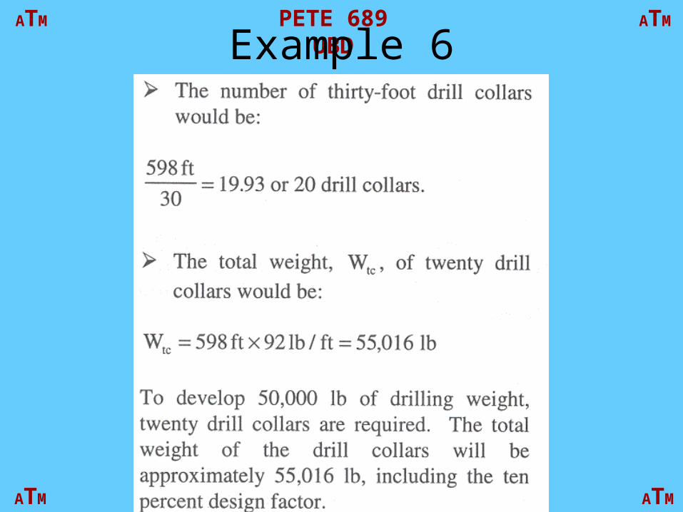
Example 6

Harold Vance Department of Petroleum Engineering
ATMPETE 689 UBDATM
ATM ATM
Example 6

Harold Vance Department of Petroleum Engineering
ATMPETE 689 UBDATM
ATM ATM
Example 6
Harold Vance Department of Petroleum Engineering
ATMPETE 689 UBDATM
ATM ATM
Example 6

Harold Vance Department of Petroleum Engineering
ATMPETE 689 UBDATM
ATM ATM
Drillstring design
• Drillpipe is usually designed with:– a design factor of 1.1– and an overpull from 50,000 - 100,000 lbf

Harold Vance Department of Petroleum Engineering
ATMPETE 689 UBDATM
ATM ATM
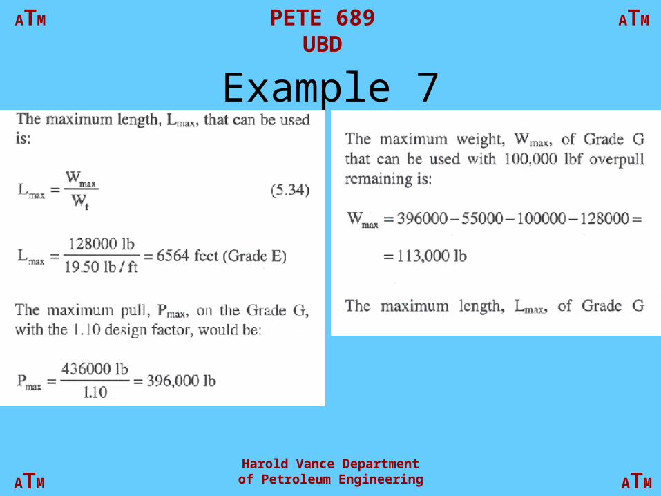
Example 7

Harold Vance Department of Petroleum Engineering
ATMPETE 689 UBDATM
ATM ATM
Example 7

Harold Vance Department of Petroleum Engineering
ATMPETE 689 UBDATM
ATM ATM
Example 7
Harold Vance Department of Petroleum Engineering
ATMPETE 689 UBDATM
ATM ATM
Example 7

Harold Vance Department of Petroleum Engineering
ATMPETE 689 UBDATM
ATM ATM
Example 7

Harold Vance Department of Petroleum Engineering
ATMPETE 689 UBDATM
ATM ATM
Separator designCapacity is a function of:
• Size
• Design and arrangement
• Number of stages
• Operating P and T
• Characteristics of fluids
• Varying gas/liquid ratio
• Size and distribution of particles
• Liquid level
• Well-fluid pattern
• Foreign material in fluids
• Foaming tendency of fluids
• Physical condition of separator
• Others

Harold Vance Department of Petroleum Engineering
ATMPETE 689 UBDATM
ATM ATM
Maximum gas velocity

Harold Vance Department of Petroleum Engineering
ATMPETE 689 UBDATM
ATM ATM

Harold Vance Department of Petroleum Engineering
ATMPETE 689 UBDATM
ATM ATM
Gas Separating Capacity

Harold Vance Department of Petroleum Engineering
ATMPETE 689 UBDATM
ATM ATM

Harold Vance Department of Petroleum Engineering
ATMPETE 689 UBDATM
ATM ATM

Harold Vance Department of Petroleum Engineering
ATMPETE 689 UBDATM
ATM ATM

Harold Vance Department of Petroleum Engineering
ATMPETE 689 UBDATM
ATM ATM