Embed Size (px)
DESCRIPTION
It is a OPNET Lab, ATM design
Citation preview
Model Descriptions Reference Manual 3 ATM Model Description
3 ATM Model Description
Asynchronous Transfer Mode (ATM) is a connection-oriented packet switching technique that is universally accepted as the transfer mode of choice for Broadband Integrated Services Digital Network. This document describes key features of the ATM model suite shipped as part of the standard OPNET model library.
Model Features
This section provides a list of the main features available in the ATM model:
• The ATM model suite captures the following protocol behavior:
• Configurable parameters for Service Specific Connection Oriented Protocol (SSCOP)
• Dynamic routing using PNNI or an adaptation of the Bellman-Ford shortest path algorithm.
• Simulation efficiency modes to reduce the duration of large simulations without sacrificing accuracy.
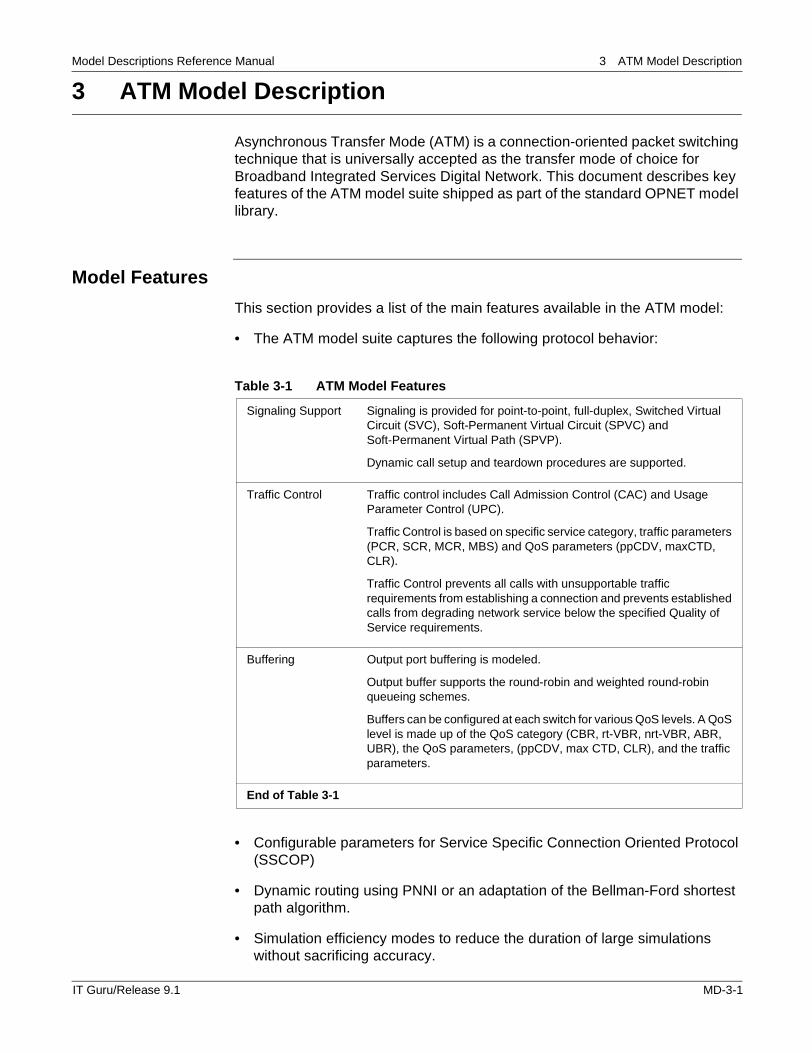
Table 3-1 ATM Model Features
Signaling Support Signaling is provided for point-to-point, full-duplex, Switched Virtual Circuit (SVC), Soft-Permanent Virtual Circuit (SPVC) and Soft-Permanent Virtual Path (SPVP).
Dynamic call setup and teardown procedures are supported.
Traffic Control Traffic control includes Call Admission Control (CAC) and Usage Parameter Control (UPC).
Traffic Control is based on specific service category, traffic parameters (PCR, SCR, MCR, MBS) and QoS parameters (ppCDV, maxCTD, CLR).
Traffic Control prevents all calls with unsupportable traffic requirements from establishing a connection and prevents established calls from degrading network service below the specified Quality of Service requirements.
Buffering Output port buffering is modeled.
Output buffer supports the round-robin and weighted round-robin queueing schemes.
Buffers can be configured at each switch for various QoS levels. A QoS level is made up of the QoS category (CBR, rt-VBR, nrt-VBR, ABR, UBR), the QoS parameters, (ppCDV, max CTD, CLR), and the traffic parameters.
End of Table 3-1
IT Guru/Release 9.1 MD-3-1
Model Descriptions Reference Manual 3 ATM Model Description
• An API package that applications can use to create, destroy, and send packets through an ATM Virtual Circuit
• SPVC Reroute capability to reroute SPVC connections on failure
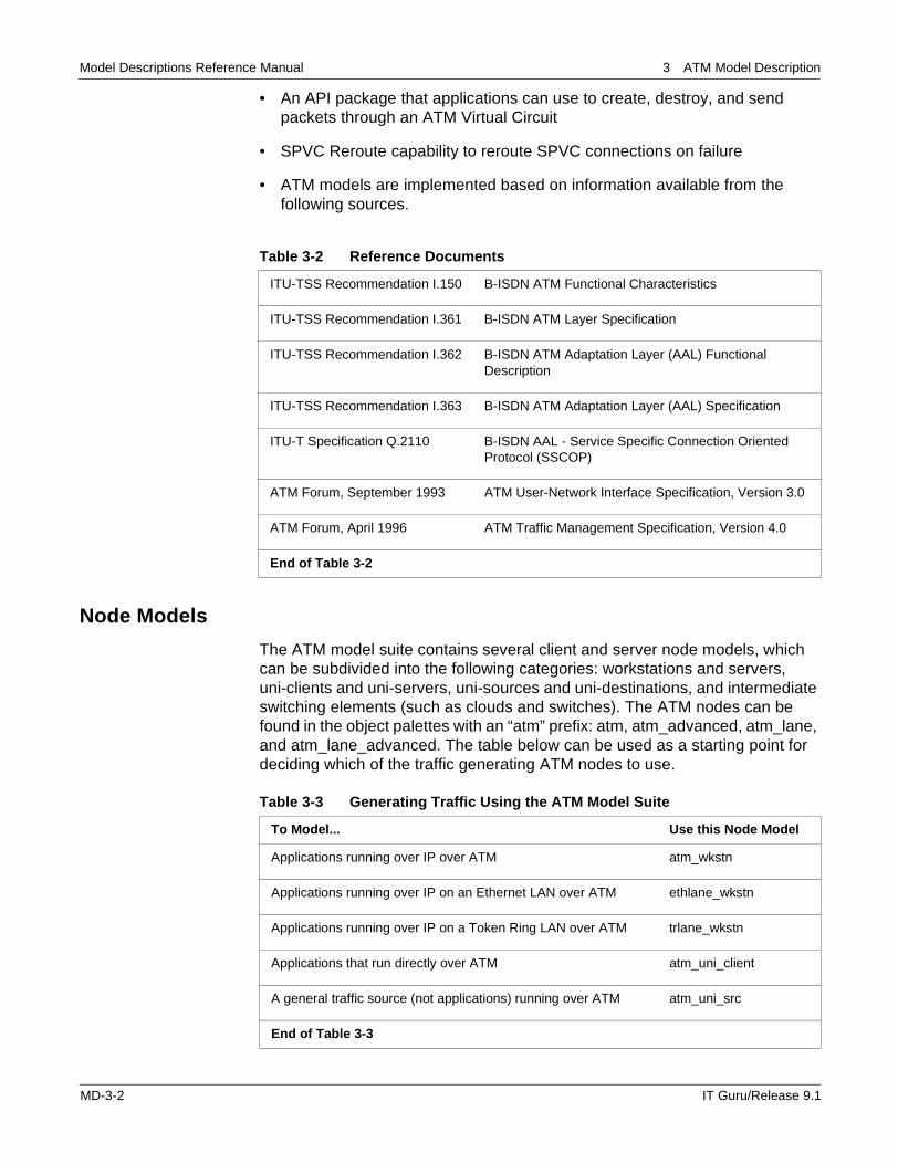
• ATM models are implemented based on information available from the following sources.
Node Models
The ATM model suite contains several client and server node models, which can be subdivided into the following categories: workstations and servers, uni-clients and uni-servers, uni-sources and uni-destinations, and intermediate switching elements (such as clouds and switches). The ATM nodes can be found in the object palettes with an “atm” prefix: atm, atm_advanced, atm_lane, and atm_lane_advanced. The table below can be used as a starting point for deciding which of the traffic generating ATM nodes to use.
Table 3-2 Reference Documents
ITU-TSS Recommendation I.150 B-ISDN ATM Functional Characteristics
ITU-TSS Recommendation I.361 B-ISDN ATM Layer Specification
ITU-TSS Recommendation I.362 B-ISDN ATM Adaptation Layer (AAL) Functional Description
ITU-TSS Recommendation I.363 B-ISDN ATM Adaptation Layer (AAL) Specification
ITU-T Specification Q.2110 B-ISDN AAL - Service Specific Connection Oriented Protocol (SSCOP)
ATM Forum, September 1993 ATM User-Network Interface Specification, Version 3.0
ATM Forum, April 1996 ATM Traffic Management Specification, Version 4.0
End of Table 3-2
Table 3-3 Generating Traffic Using the ATM Model Suite
To Model... Use this Node Model
Applications running over IP over ATM atm_wkstn
Applications running over IP on an Ethernet LAN over ATM ethlane_wkstn
Applications running over IP on a Token Ring LAN over ATM trlane_wkstn
Applications that run directly over ATM atm_uni_client
A general traffic source (not applications) running over ATM atm_uni_src
End of Table 3-3
MD-3-2 IT Guru/Release 9.1
Model Descriptions Reference Manual 3 ATM Model Description
The main features of the various types of ATM node models are described below. For additional information on specific node models, right-click on the node in the project workspace and select View Node Description from the pop-up menu.
Workstations and Servers
Workstations
The atm_wkstn model features an application layer that resides over an IP layer, which in turn resides over the ATM layer. The application layer supports all of the OPNET application models; specifically, the standard network application and custom application models.
All data going to the same destination is multiplexed into a single ATM connection, regardless of the application the data is from. The atm_wkstn node model is found on the atm object palette, whereas the corresponding intermediate and advanced models are located on the atm_advanced object palette.
The basic atm_wkstn model, like all of OPNET’s basic models, has the same functionality as the intermediate and advanced versions, but certain attributes are hidden from view. To change the value of attributes that are hidden in the basic model, switch to a model with an _int or _adv suffix.
Servers
The atm_server node model is used with the workstation described above (atm_wkstn). This server can support all of the application models. The atm_server node model is found in the atm object palette, whereas the intermediate and advanced versions are located on the atm_advanced object palette.
LANE (LAN Emulation) Workstations and Servers
The ATM LANE workstations and servers have the same functionality as the main ATM workstations and servers described above, with the additional feature of supporting LAN emulation (Ethernet or Token Ring). In the workstation nodes, the application layer resides over IP over LANE over ATM. The LANE node models are located on the atm_lane and atm_lane_advanced object palettes. The models are:
• ethlane_wkstn, trlane_wkstn
• ethlane_server, ethlane_service, trlane_server, trlane_service
IT Guru/Release 9.1 MD-3-3
Model Descriptions Reference Manual 3 ATM Model Description
Uni-clients and Uni-servers
These client node models feature an application layer that resides directly over the ATM layer. Unlike the ATM workstation node model, the ATM uni-client model establishes a separate ATM connection for each application task. Examples of application tasks are sending an e-mail, downloading a file, and making a voice call. ATM uni-clients can be used only with ATM uni-servers, which are capable of supporting all of the application services.
The ATM uni-client and uni-server node models are located in the atm_advanced object palette. The models are:
• atm_uni_client
• atm_uni_server
Uni-sources and Uni-destinations
These node models are unlike the workstations and clients described so far, in that they do not use the application models to generate traffic. Instead, traffic is generated by a raw packet generator, which resides over the ATM layer. The raw packet generator enables you to specify traffic in terms of packets — by specifying values for packet sizes and packet interarrival times.
The atm_uni_source and atm_uni_dest nodes are always used together, since the atm_uni_source node can only generate traffic, but not receive it, while the atm_uni_dest node can only receive traffic. The traffic generated by one atm_uni_source node can be distributed amongst several atm_uni_dest nodes. Similarly, an atm_uni_dest node can receive traffic from one or more atm_uni_source nodes. The models are:
• atm_uni_src
• atm_uni_dest
Switching Elements
Switching elements in the network topology neither generate nor sink traffic. Instead, they retain connection information related to the network and switch incoming packets through a fabric. The atm_cloud node models aggregated switching elements, which would typically be a service provider’s network. You can specify values for the loss and delay across the aggregation. The models are:
• atm_<switch_name>
• atm_cloud
MD-3-4 IT Guru/Release 9.1
Model Descriptions Reference Manual 3 ATM Model Description
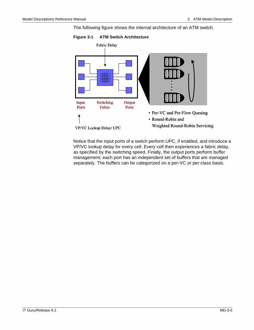
The following figure shows the internal architecture of an ATM switch.
Figure 3-1 ATM Switch Architecture
Notice that the input ports of a switch perform UPC, if enabled, and introduce a VP/VC lookup delay for every cell. Every cell then experiences a fabric delay, as specified by the switching speed. Finally, the output ports perform buffer management; each port has an independent set of buffers that are managed separately. The buffers can be categorized on a per-VC or per-class basis.
• Per-VC and Per-Flow Queuing• Round-Robin and
Weighted Round-Robin Servicing
Output Buffering
Input Ports
SwitchingFabric
OutputPorts
Fabric Delay
VP/VC Lookup Delay/ UPC
• Per-VC and Per-Flow Queuing• Round-Robin and
Weighted Round-Robin Servicing
Output BufferingOutput Buffering
Input Ports
SwitchingFabric
OutputPorts
Fabric Delay
VP/VC Lookup Delay/ UPC
IT Guru/Release 9.1 MD-3-5
Model Descriptions Reference Manual 3 ATM Model Description
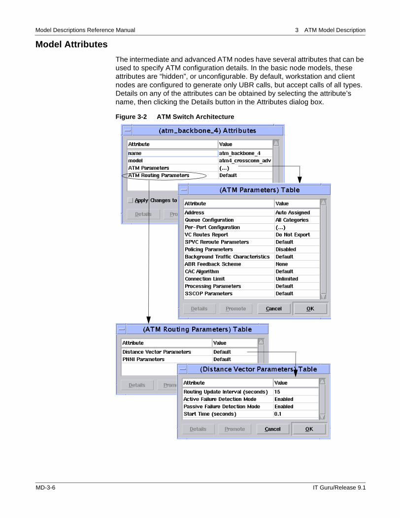
Model Attributes
The intermediate and advanced ATM nodes have several attributes that can be used to specify ATM configuration details. In the basic node models, these attributes are “hidden”, or unconfigurable. By default, workstation and client nodes are configured to generate only UBR calls, but accept calls of all types. Details on any of the attributes can be obtained by selecting the attribute’s name, then clicking the Details button in the Attributes dialog box.
Figure 3-2 ATM Switch Architecture
MD-3-6 IT Guru/Release 9.1
Model Descriptions Reference Manual 3 ATM Model Description
Some of the important ATM model attributes are listed below.
• Traffic Contract. Based on the type of ATM node being used, this attribute has appropriate names:
— ATM IP Parameters->SVC Characteristics->Traffic Contract (IP)
— ATM LANE Parameters (LANE)
— ATM Application Parameters (UNI-Client and UNI-Sources)
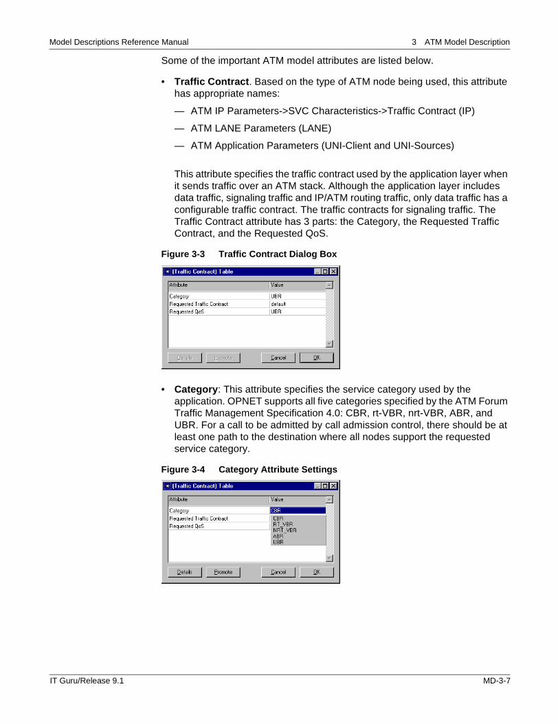
This attribute specifies the traffic contract used by the application layer when it sends traffic over an ATM stack. Although the application layer includes data traffic, signaling traffic and IP/ATM routing traffic, only data traffic has a configurable traffic contract. The traffic contracts for signaling traffic. The Traffic Contract attribute has 3 parts: the Category, the Requested Traffic Contract, and the Requested QoS.
Figure 3-3 Traffic Contract Dialog Box
• Category: This attribute specifies the service category used by the application. OPNET supports all five categories specified by the ATM Forum Traffic Management Specification 4.0: CBR, rt-VBR, nrt-VBR, ABR, and UBR. For a call to be admitted by call admission control, there should be at least one path to the destination where all nodes support the requested service category.
Figure 3-4 Category Attribute Settings
IT Guru/Release 9.1 MD-3-7
Model Descriptions Reference Manual 3 ATM Model Description
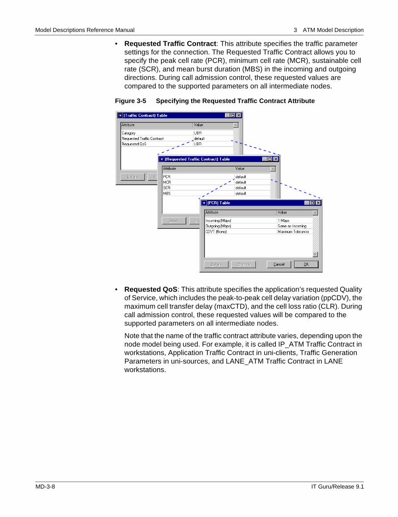
• Requested Traffic Contract: This attribute specifies the traffic parameter settings for the connection. The Requested Traffic Contract allows you to specify the peak cell rate (PCR), minimum cell rate (MCR), sustainable cell rate (SCR), and mean burst duration (MBS) in the incoming and outgoing directions. During call admission control, these requested values are compared to the supported parameters on all intermediate nodes.
Figure 3-5 Specifying the Requested Traffic Contract Attribute
• Requested QoS: This attribute specifies the application’s requested Quality of Service, which includes the peak-to-peak cell delay variation (ppCDV), the maximum cell transfer delay (maxCTD), and the cell loss ratio (CLR). During call admission control, these requested values will be compared to the supported parameters on all intermediate nodes.
Note that the name of the traffic contract attribute varies, depending upon the node model being used. For example, it is called IP_ATM Traffic Contract in workstations, Application Traffic Contract in uni-clients, Traffic Generation Parameters in uni-sources, and LANE_ATM Traffic Contract in LANE workstations.
MD-3-8 IT Guru/Release 9.1
Model Descriptions Reference Manual 3 ATM Model Description
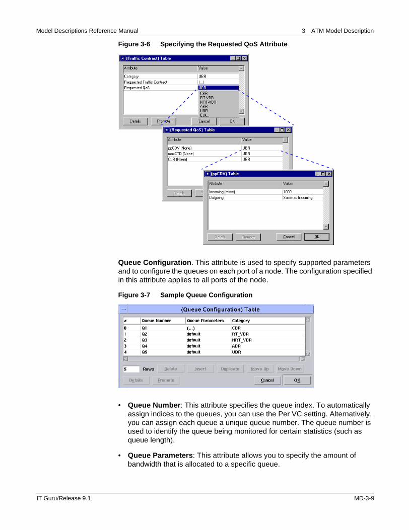
Figure 3-6 Specifying the Requested QoS Attribute
Queue Configuration. This attribute is used to specify supported parameters and to configure the queues on each port of a node. The configuration specified in this attribute applies to all ports of the node.
Figure 3-7 Sample Queue Configuration
• Queue Number: This attribute specifies the queue index. To automatically assign indices to the queues, you can use the Per VC setting. Alternatively, you can assign each queue a unique queue number. The queue number is used to identify the queue being monitored for certain statistics (such as queue length).
• Queue Parameters: This attribute allows you to specify the amount of bandwidth that is allocated to a specific queue.
IT Guru/Release 9.1 MD-3-9
Model Descriptions Reference Manual 3 ATM Model Description
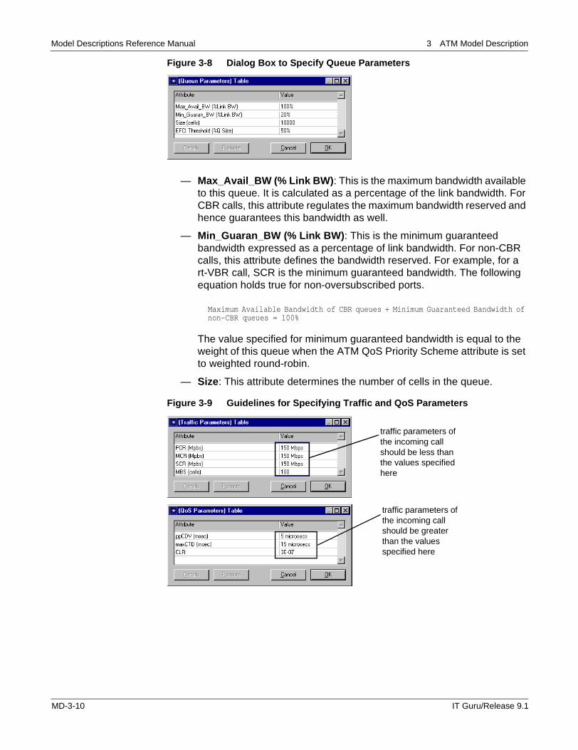
Figure 3-8 Dialog Box to Specify Queue Parameters
— Max_Avail_BW (% Link BW): This is the maximum bandwidth available to this queue. It is calculated as a percentage of the link bandwidth. For CBR calls, this attribute regulates the maximum bandwidth reserved and hence guarantees this bandwidth as well.
— Min_Guaran_BW (% Link BW): This is the minimum guaranteed bandwidth expressed as a percentage of link bandwidth. For non-CBR calls, this attribute defines the bandwidth reserved. For example, for a rt-VBR call, SCR is the minimum guaranteed bandwidth. The following equation holds true for non-oversubscribed ports.
Maximum Available Bandwidth of CBR queues + Minimum Guaranteed Bandwidth of non-CBR queues = 100%
The value specified for minimum guaranteed bandwidth is equal to the weight of this queue when the ATM QoS Priority Scheme attribute is set to weighted round-robin.
— Size: This attribute determines the number of cells in the queue.
Figure 3-9 Guidelines for Specifying Traffic and QoS Parameters
traffic parameters of the incoming call should be less than the values specified here
traffic parameters of the incoming call should be greater than the values specified here
MD-3-10 IT Guru/Release 9.1
Model Descriptions Reference Manual 3 ATM Model Description
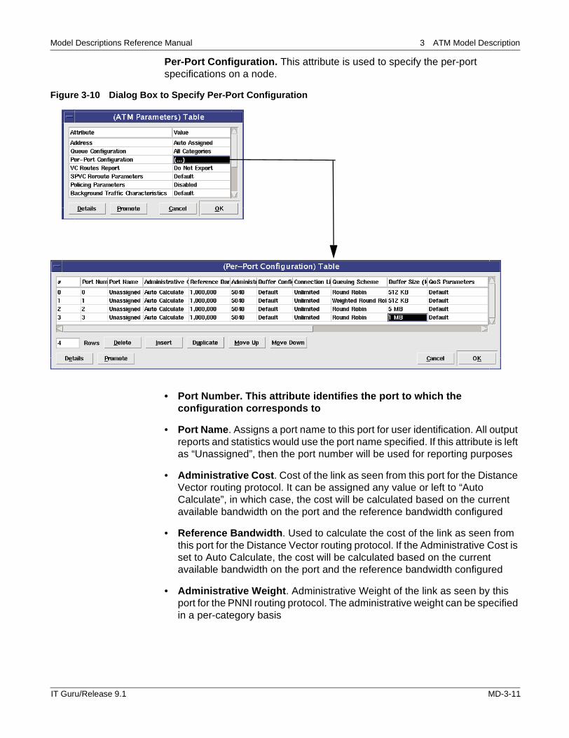
Per-Port Configuration. This attribute is used to specify the per-port specifications on a node.
Figure 3-10 Dialog Box to Specify Per-Port Configuration.
• Port Number. This attribute identifies the port to which the configuration corresponds to
• Port Name. Assigns a port name to this port for user identification. All output reports and statistics would use the port name specified. If this attribute is left as “Unassigned”, then the port number will be used for reporting purposes
• Administrative Cost. Cost of the link as seen from this port for the Distance Vector routing protocol. It can be assigned any value or left to “Auto Calculate”, in which case, the cost will be calculated based on the current available bandwidth on the port and the reference bandwidth configured
• Reference Bandwidth. Used to calculate the cost of the link as seen from this port for the Distance Vector routing protocol. If the Administrative Cost is set to Auto Calculate, the cost will be calculated based on the current available bandwidth on the port and the reference bandwidth configured
• Administrative Weight. Administrative Weight of the link as seen by this port for the PNNI routing protocol. The administrative weight can be specified in a per-category basis
IT Guru/Release 9.1 MD-3-11
Model Descriptions Reference Manual 3 ATM Model Description
• Buffer Configuration. This attribute is the same as the “Queue Configuration” attribute but on a per-port basis. When left to default, the value of this attribute defaults to the top level common “Queue Configuration” attribute. If this attribute is explicitly specified, then the top level attribute will be ignored
• Connection Limit. Maximum number of VCs that can be routed through this port at any point of time
• Queuing Scheme. Specifies the queuing scheme for scheduling packets for different queues within a port. The two queueing schemes available are round robin and weighted round robin
• Buffer Size. Buffer size in Megabytes that is shared by all queues on this port. There is a “Queue Size” attribute in cells on a per-queue basis. The queue will start to drop packets (overflow) if either the buffer size limit or the queue size limit is reached
• QoS Parameters. Specifies the supported quality of service parameters on a per-category per-port basis, which include the peak-to-peak cell delay variation, the maximum cell transfer delay and the cell loss ratio
Policing Parameters. This attribute is used to specify the usage policy control (UPC) function. After a connection is set up, the incoming traffic may violate the traffic contract that was requested when the connection was made. This policy control mechanism determines whether the incoming data conforms to the traffic contract specified during connection setup. The Policing functionality can be enabled by setting this attribute to either the Tagging or Discard Option.
• Tagging Option: non-conforming cells are tagged with the CLP bit set to a high value.
• Discard Option: non-conforming cells are tagged and then discarded.
The Policing functionality is a dual leaky bucket implementation that polices for the peak cell rate (PCR) of the incoming traffic. In VBR virtual circuits, a dual leaky bucket polices for both the peak cell rate (PCR) and the sustainable cell rate (SCR) of the incoming cells.
SPVC Reroute Parameters. This compound attribute specifies the number of SPVC reroute attempts and the time between the attempts for re-routing SPVC connections on failure.There are link attributes to export reports on a particular link:
• ATM Link Failure Report: Exports the number of VCs traversing the link at the time of failure, number of rerouted connections and the paths taken by the rerouted connections
• ATM Trunk Report: Exports the number of VCs traversing the trunk at the specified time and the bandwidth allocated on the trunk at the specified time
MD-3-12 IT Guru/Release 9.1
Model Descriptions Reference Manual 3 ATM Model Description
Processing Parameters. Parameters used to compute processing time of the packet within a node
• VC Lookup Delay. This attribute specifies the processing delay for VP/VC (Virtual Path/Virtual Connection) Switching.
• VP Lookup Delay. This attribute specifies the processing delay for VP Switching.VC and VP lookup delays model the effect of lookup in the switching tables to determine the output VPI and VCI, since these identifiers are of local significance.
• Switching Speed. This attribute specifies how fast a cell is switched through the core switching fabric. This speed is specified in cells/sec
• Segmentation Rate. Rate at which the incoming higher layer packets are segmented into AAL PDUs.
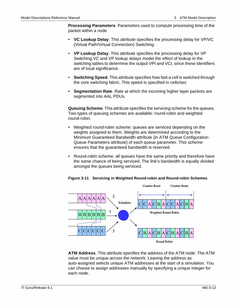
Queuing Scheme. This attribute specifies the servicing scheme for the queues. Two types of queuing schemes are available: round-robin and weighted round-robin.
• Weighted round-robin scheme: queues are serviced depending on the weights assigned to them. Weights are determined according to the Minimum Guaranteed Bandwidth attribute (in ATM Queue Configuration · Queue Parameters attribute) of each queue parameter. This scheme ensures that the guaranteed bandwidth is reserved.
• Round-robin scheme: all queues have the same priority and therefore have the same chance of being serviced. The link’s bandwidth is equally divided amongst the queues being serviced.
Figure 3-11 Servicing in Weighted Round-robin and Round-robin Schemes
ATM Address. This attribute specifies the address of the ATM node. The ATM value must be unique across the network. Leaving the address as auto-assigned selects unique ATM addresses at the start of a simulation. You can choose to assign addresses manually by specifying a unique integer for each node.
AAAAAA
BBBBBB
CCCCCC
ABCACCABCAC
2
1
3
C
Counter Reset
ABCABCABCABC
Weighted Round Robin
Round Robin
Scheduler
Counter Reset
AAAAAA
BBBBBB
CCCCCC
ABCACCABCAC
2
1
3
C
Counter Reset
ABCABCABCABC
Weighted Round Robin
Round Robin
Scheduler
Counter Reset
IT Guru/Release 9.1 MD-3-13
Model Descriptions Reference Manual 3 ATM Model Description
AAL Layer Selection. This attribute specifies the adaptation layer used by a node. The atm_uni_src node can establish many ATM connections with different traffic contracts for each connection; each connection can specify its own AAL type.
In the atm_uni_src node model, this attribute appears as a sub-attribute of the Traffic Generation Parameters attribute. For the other workstation and client nodes, use the “Application Transport Layer Protocol” attribute to specify the AAL type for each application.
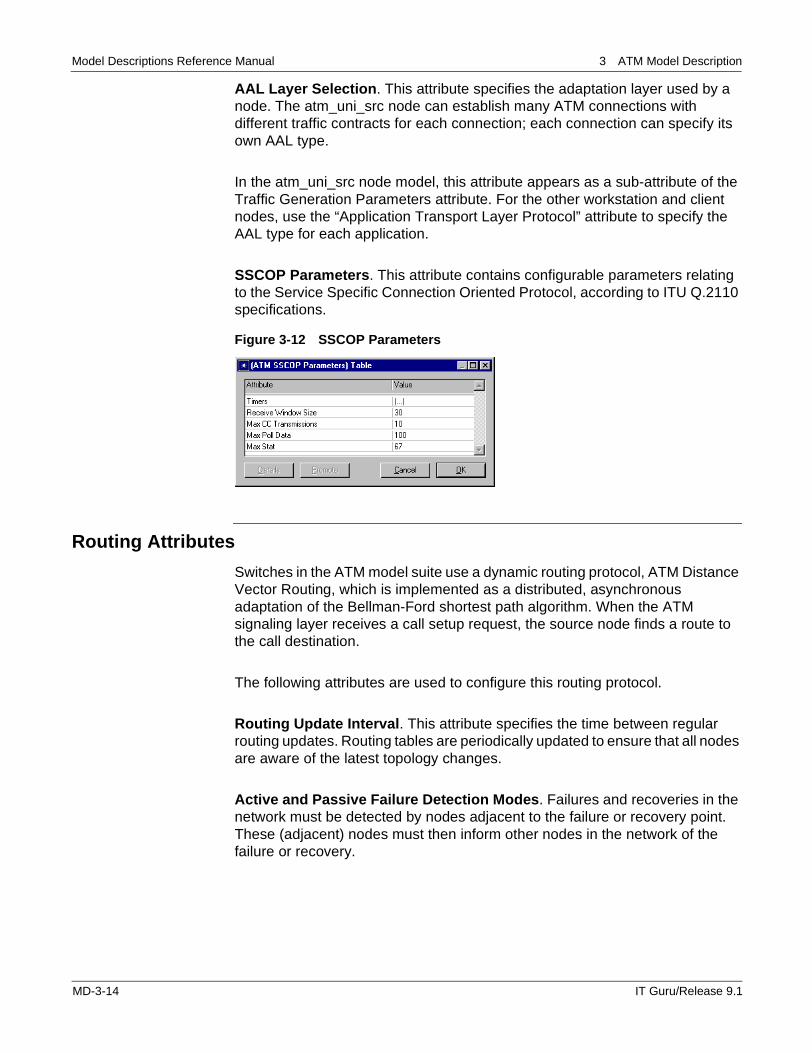
SSCOP Parameters. This attribute contains configurable parameters relating to the Service Specific Connection Oriented Protocol, according to ITU Q.2110 specifications.
Figure 3-12 SSCOP Parameters
Routing Attributes
Switches in the ATM model suite use a dynamic routing protocol, ATM Distance Vector Routing, which is implemented as a distributed, asynchronous adaptation of the Bellman-Ford shortest path algorithm. When the ATM signaling layer receives a call setup request, the source node finds a route to the call destination.
The following attributes are used to configure this routing protocol.
Routing Update Interval. This attribute specifies the time between regular routing updates. Routing tables are periodically updated to ensure that all nodes are aware of the latest topology changes.
Active and Passive Failure Detection Modes. Failures and recoveries in the network must be detected by nodes adjacent to the failure or recovery point. These (adjacent) nodes must then inform other nodes in the network of the failure or recovery.
MD-3-14 IT Guru/Release 9.1
Model Descriptions Reference Manual 3 ATM Model Description
• active failure detection mode: the routing process detects a neighbor node or link failure/recovery and updates its routing tables immediately. The node sends out route advertisements that reflect its updated routing table.
• passive failure detection mode: failure is detected implicitly when no route costs have been received in two or more route update periods.
See the PNNI Model Description document for details on PNNI parameters.
Simulation Attributes
Simulation attributes can be used to reduce the simulation run time duration. By enabling one or more of the simulation attributes, you can reduce the amount of time needed for the simulation to run, without sacrificing the accuracy of your results.
The ATM simulation attributes are described below:
ATM Dynamic Routing Protocol. This simulation attribute determines the routing protocol used by the ATM switches. When this simulation attribute is set to Distance Vector, all switches in the network use the Distance Vector Routing Protocol, as described in the Switch Attributes section. Using the Fast-Mode PNNI setting reduces simulation run time by using the static PNNI routing protocol whereas using the Explicit-Mode PNNI would run the full blown PNNI routing protocol on all nodes.
ATM SSCOP Sim Efficiency Mode. When this simulation attribute is set to enabled, the IDLE timer is set to infinity. The IDLE timer is started when there is no outstanding data waiting to be acknowledged or any pending data to be transmitted. When data traffic begins, the SSCOP process transitions from the IDLE phase to the active phase. When this simulation attribute is enabled, the SSCOP process will not be able to detect link or node failures when there is no data traffic between the peer processes. Therefore, you should disable this attribute if you are studying node and link failures.
ATM Sim Efficiency. When this simulation attribute is set to Enabled, cells are delivered directly to the destination nodes and are not transmitted via the link pipeline stages. Propagation and transmission delays are computed internally. This efficiency attribute increases simulation speed by reducing the total number of events. Note that you cannot collect link utilization and throughput statistics if this efficiency mode is enabled.
IT Guru/Release 9.1 MD-3-15
Model Descriptions Reference Manual 3 ATM Model Description
compound_cell_enabled. When this simulation attribute is set to enabled, packets are sent into the ATM network without being segmented into cells. However, overheads and segmentation delays are computed. Although this efficiency mode affects the value of statistics monitored at the ATM layer (such as cell delay, cell loss ratio, and cell delay variation), statistics monitored at higher layers are unaffected.
Available Statistics
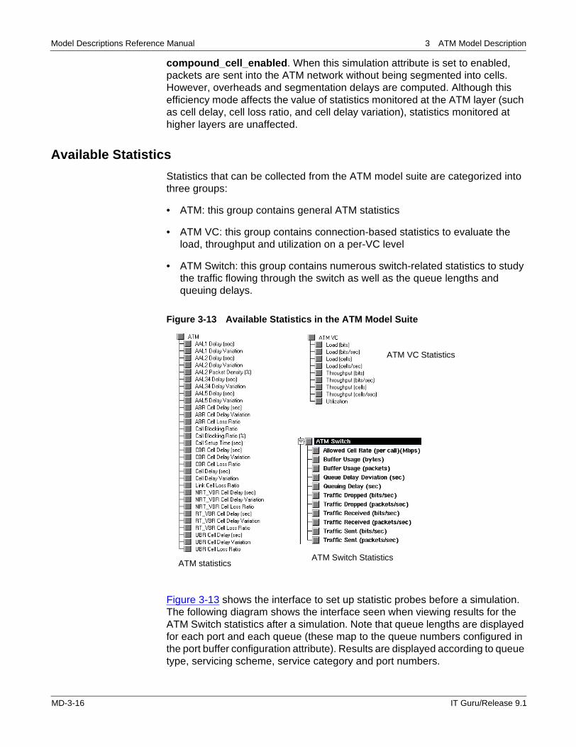
Statistics that can be collected from the ATM model suite are categorized into three groups:
• ATM: this group contains general ATM statistics
• ATM VC: this group contains connection-based statistics to evaluate the load, throughput and utilization on a per-VC level
• ATM Switch: this group contains numerous switch-related statistics to study the traffic flowing through the switch as well as the queue lengths and queuing delays.
Figure 3-13 Available Statistics in the ATM Model Suite
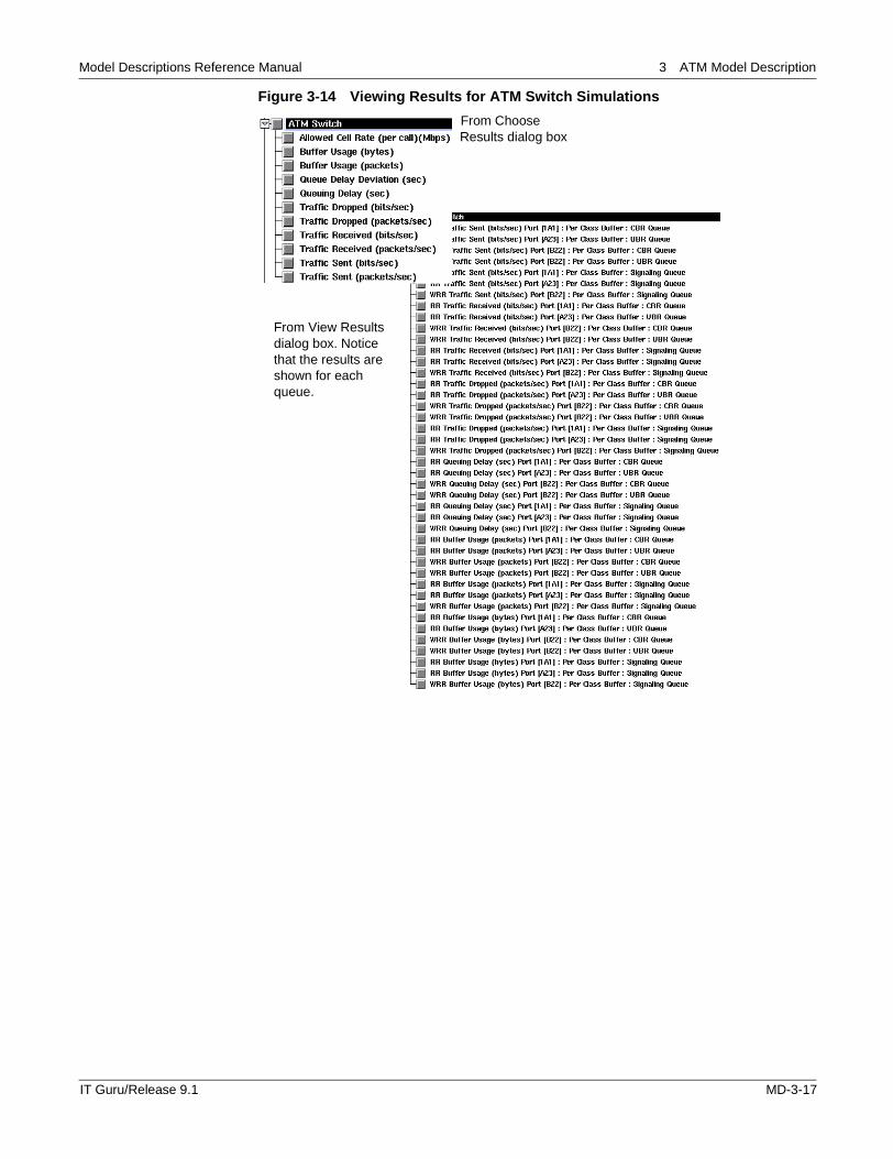
Figure 3-13 shows the interface to set up statistic probes before a simulation. The following diagram shows the interface seen when viewing results for the ATM Switch statistics after a simulation. Note that queue lengths are displayed for each port and each queue (these map to the queue numbers configured in the port buffer configuration attribute). Results are displayed according to queue type, servicing scheme, service category and port numbers.
ATM statistics
ATM VC Statistics
ATM Switch Statistics
MD-3-16 IT Guru/Release 9.1
Model Descriptions Reference Manual 3 ATM Model Description
Figure 3-14 Viewing Results for ATM Switch Simulations
From Choose Results dialog box
From View Results dialog box. Notice that the results are shown for each queue.
IT Guru/Release 9.1 MD-3-17
Model Descriptions Reference Manual 3 ATM Model Description
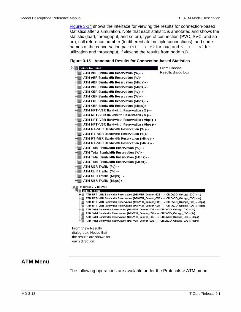
Figure 3-14 shows the interface for viewing the results for connection-based statistics after a simulation. Note that each statistic is annotated and shows the statistic (load, throughput, and so on), type of connection (PVC, SVC, and so on), call reference number (to differentiate multiple connections), and node names of the conversation pair (n1 --> n2 for load and n1 <-- n2 for utilization and throughput, if viewing the results from node n1).
Figure 3-15 Annotated Results for Connection-based Statistics
ATM Menu
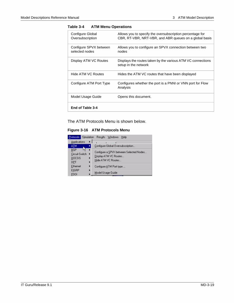
The following operations are available under the Protocols > ATM menu.
From View Results dialog box. Notice that the results are shown for each direction
From Choose Results dialog box
MD-3-18 IT Guru/Release 9.1
Model Descriptions Reference Manual 3 ATM Model Description
The ATM Protocols Menu is shown below.
Figure 3-16 ATM Protocols Menu
Table 3-4 ATM Menu Operations
Configure Global Oversubscription
Allows you to specify the oversubscription percentage for CBR, RT-VBR, NRT-VBR, and ABR queues on a global basis
Configure SPVX between selected nodes
Allows you to configure an SPVX connection between two nodes
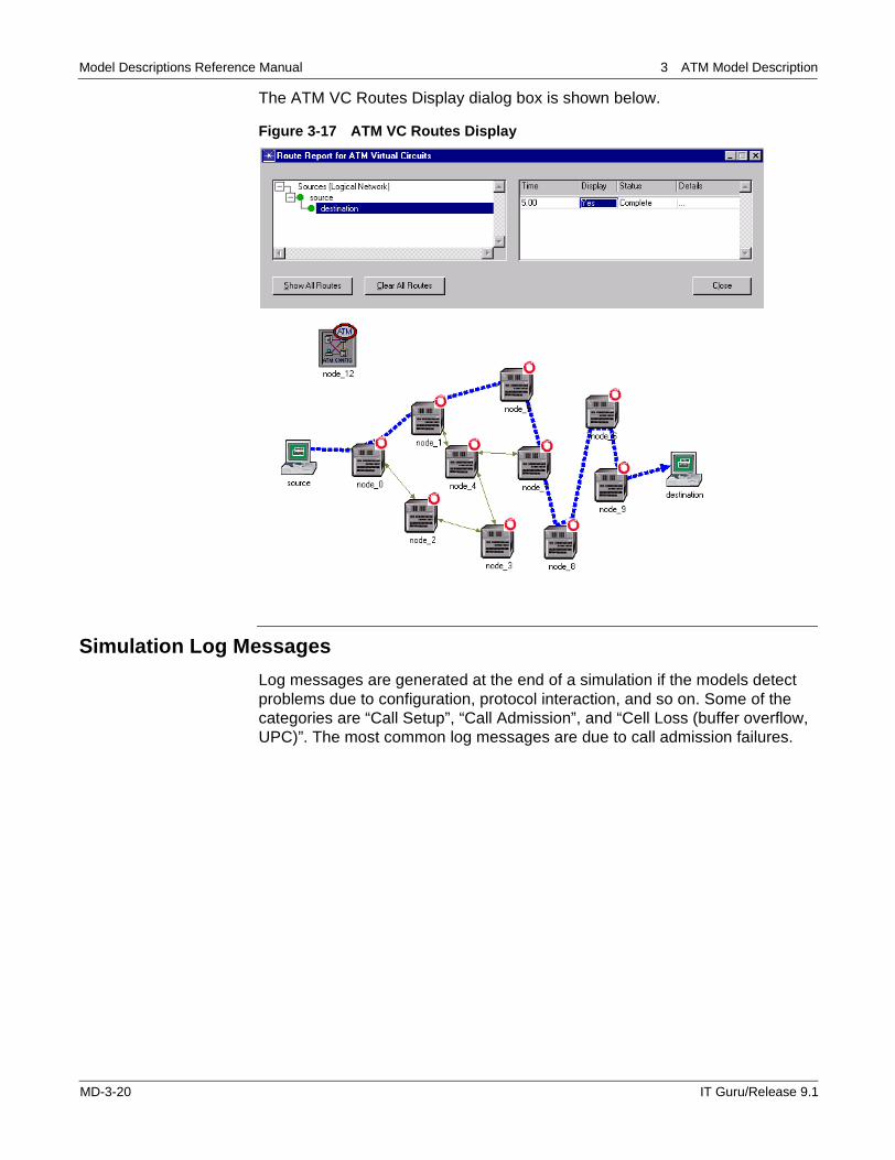
Display ATM VC Routes Displays the routes taken by the various ATM VC connections setup in the network
Hide ATM VC Routes Hides the ATM VC routes that have been displayed
Configure ATM Port Type Configures whether the port is a PNNI or VNN port for Flow Analysis
Model Usage Guide Opens this document.
End of Table 3-4
IT Guru/Release 9.1 MD-3-19
Model Descriptions Reference Manual 3 ATM Model Description
The ATM VC Routes Display dialog box is shown below.
Figure 3-17 ATM VC Routes Display
Simulation Log Messages
Log messages are generated at the end of a simulation if the models detect problems due to configuration, protocol interaction, and so on. Some of the categories are “Call Setup”, “Call Admission”, and “Cell Loss (buffer overflow, UPC)”. The most common log messages are due to call admission failures.
MD-3-20 IT Guru/Release 9.1
Model Descriptions Reference Manual 3 ATM Model Description
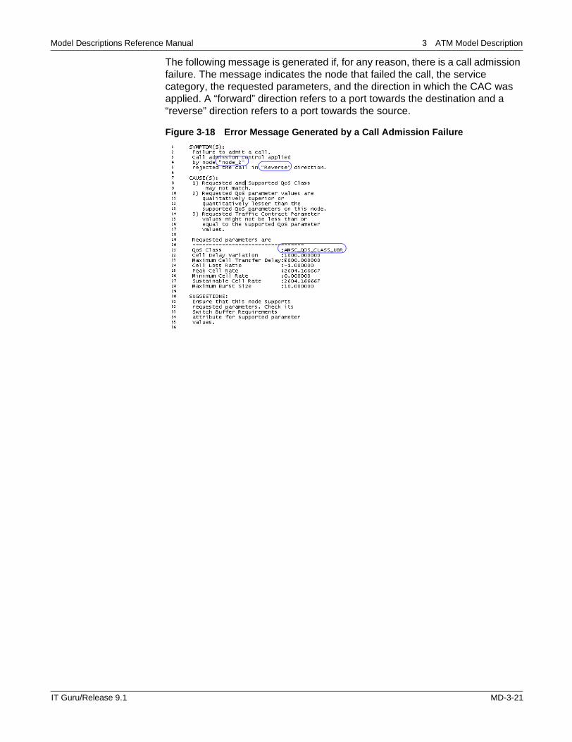
The following message is generated if, for any reason, there is a call admission failure. The message indicates the node that failed the call, the service category, the requested parameters, and the direction in which the CAC was applied. A “forward” direction refers to a port towards the destination and a “reverse” direction refers to a port towards the source.
Figure 3-18 Error Message Generated by a Call Admission Failure
IT Guru/Release 9.1 MD-3-21
Model Descriptions Reference Manual 3 ATM Model Description
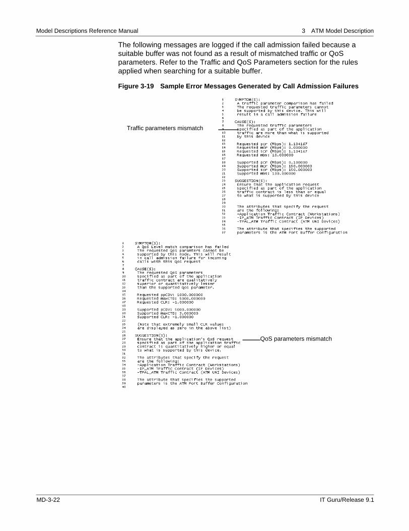
The following messages are logged if the call admission failed because a suitable buffer was not found as a result of mismatched traffic or QoS parameters. Refer to the Traffic and QoS Parameters section for the rules applied when searching for a suitable buffer.
Figure 3-19 Sample Error Messages Generated by Call Admission Failures
Traffic parameters mismatch
QoS parameters mismatch
MD-3-22 IT Guru/Release 9.1
Model Descriptions Reference Manual 3 ATM Model Description
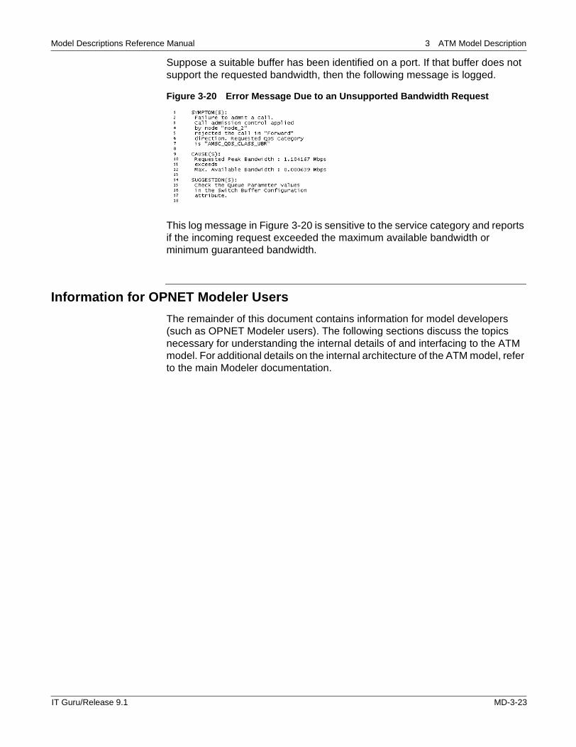
Suppose a suitable buffer has been identified on a port. If that buffer does not support the requested bandwidth, then the following message is logged.
Figure 3-20 Error Message Due to an Unsupported Bandwidth Request
This log message in Figure 3-20 is sensitive to the service category and reports if the incoming request exceeded the maximum available bandwidth or minimum guaranteed bandwidth.
Information for OPNET Modeler Users
The remainder of this document contains information for model developers (such as OPNET Modeler users). The following sections discuss the topics necessary for understanding the internal details of and interfacing to the ATM model. For additional details on the internal architecture of the ATM model, refer to the main Modeler documentation.
IT Guru/Release 9.1 MD-3-23
Model Descriptions Reference Manual 3 ATM Model Description
Model Architecture
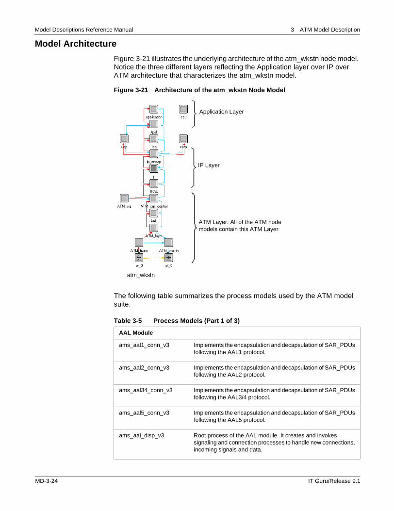
Figure 3-21 illustrates the underlying architecture of the atm_wkstn node model. Notice the three different layers reflecting the Application layer over IP over ATM architecture that characterizes the atm_wkstn model.
Figure 3-21 Architecture of the atm_wkstn Node Model
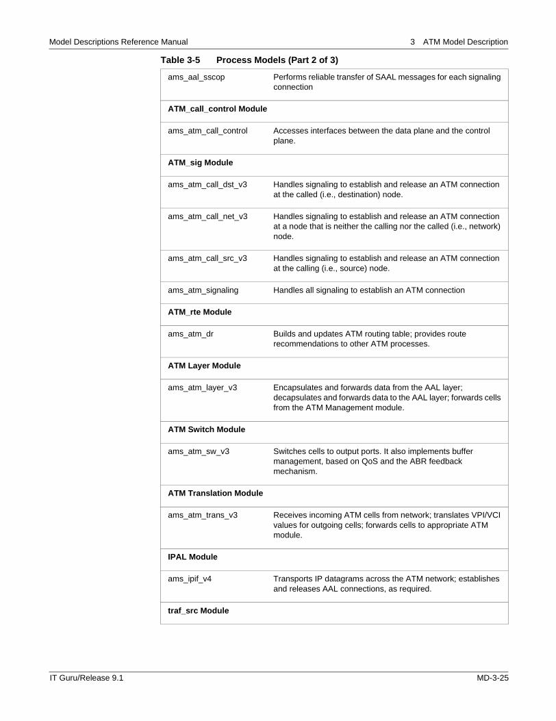
The following table summarizes the process models used by the ATM model suite.
Table 3-5 Process Models (Part 1 of 3)
AAL Module
ams_aal1_conn_v3 Implements the encapsulation and decapsulation of SAR_PDUs following the AAL1 protocol.
ams_aal2_conn_v3 Implements the encapsulation and decapsulation of SAR_PDUs following the AAL2 protocol.
ams_aal34_conn_v3 Implements the encapsulation and decapsulation of SAR_PDUs following the AAL3/4 protocol.
ams_aal5_conn_v3 Implements the encapsulation and decapsulation of SAR_PDUs following the AAL5 protocol.
ams_aal_disp_v3 Root process of the AAL module. It creates and invokes signaling and connection processes to handle new connections, incoming signals and data.
atm_wkstn
Application Layer
IP Layer
ATM Layer. All of the ATM node models contain this ATM Layer
MD-3-24 IT Guru/Release 9.1
Model Descriptions Reference Manual 3 ATM Model Description
ams_aal_sscop Performs reliable transfer of SAAL messages for each signaling connection
ATM_call_control Module
ams_atm_call_control Accesses interfaces between the data plane and the control plane.
ATM_sig Module
ams_atm_call_dst_v3 Handles signaling to establish and release an ATM connection at the called (i.e., destination) node.
ams_atm_call_net_v3 Handles signaling to establish and release an ATM connection at a node that is neither the calling nor the called (i.e., network) node.
ams_atm_call_src_v3 Handles signaling to establish and release an ATM connection at the calling (i.e., source) node.
ams_atm_signaling Handles all signaling to establish an ATM connection
ATM_rte Module
ams_atm_dr Builds and updates ATM routing table; provides route recommendations to other ATM processes.
ATM Layer Module
ams_atm_layer_v3 Encapsulates and forwards data from the AAL layer; decapsulates and forwards data to the AAL layer; forwards cells from the ATM Management module.
ATM Switch Module
ams_atm_sw_v3 Switches cells to output ports. It also implements buffer management, based on QoS and the ABR feedback mechanism.
ATM Translation Module
ams_atm_trans_v3 Receives incoming ATM cells from network; translates VPI/VCI values for outgoing cells; forwards cells to appropriate ATM module.
IPAL Module
ams_ipif_v4 Transports IP datagrams across the ATM network; establishes and releases AAL connections, as required.
traf_src Module
Table 3-5 Process Models (Part 2 of 3)
IT Guru/Release 9.1 MD-3-25
Model Descriptions Reference Manual 3 ATM Model Description
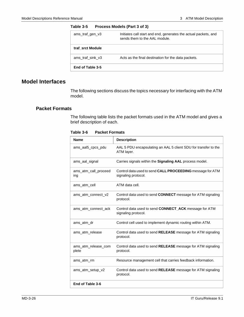
Model Interfaces
The following sections discuss the topics necessary for interfacing with the ATM model.
Packet Formats
The following table lists the packet formats used in the ATM model and gives a brief description of each.
ams_traf_gen_v3 Initiates call start and end, generates the actual packets, and sends them to the AAL module.
traf_srct Module
ams_traf_sink_v3 Acts as the final destination for the data packets.
End of Table 3-5
Table 3-5 Process Models (Part 3 of 3)
Table 3-6 Packet Formats
Name Description
ams_aal5_cpcs_pdu AAL 5 PDU encapsulating an AAL 5 client SDU for transfer to the ATM layer.
ams_aal_signal Carries signals within the Signaling AAL process model.
ams_atm_call_proceeding
Control data used to send CALL PROCEEDING message for ATM signaling protocol.
ams_atm_cell ATM data cell.
ams_atm_connect_v2 Control data used to send CONNECT message for ATM signaling protocol.
ams_atm_connect_ack Control data used to send CONNECT_ACK message for ATM signaling protocol.
ams_atm_dr Control cell used to implement dynamic routing within ATM.
ams_atm_release Control data used to send RELEASE message for ATM signaling protocol.
ams_atm_release_complete
Control data used to send RELEASE message for ATM signaling protocol.
ams_atm_rm Resource management cell that carries feedback information.
ams_atm_setup_v2 Control data used to send RELEASE message for ATM signaling protocol.
End of Table 3-6
MD-3-26 IT Guru/Release 9.1
Model Descriptions Reference Manual 3 ATM Model Description
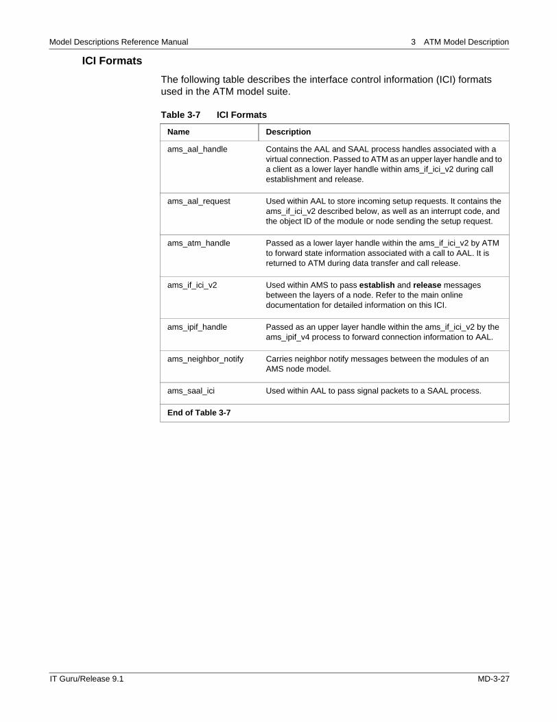
ICI Formats
The following table describes the interface control information (ICI) formats used in the ATM model suite.
Table 3-7 ICI Formats
Name Description
ams_aal_handle Contains the AAL and SAAL process handles associated with a virtual connection. Passed to ATM as an upper layer handle and to a client as a lower layer handle within ams_if_ici_v2 during call establishment and release.
ams_aal_request Used within AAL to store incoming setup requests. It contains the ams_if_ici_v2 described below, as well as an interrupt code, and the object ID of the module or node sending the setup request.
ams_atm_handle Passed as a lower layer handle within the ams_if_ici_v2 by ATM to forward state information associated with a call to AAL. It is returned to ATM during data transfer and call release.
ams_if_ici_v2 Used within AMS to pass establish and release messages between the layers of a node. Refer to the main online documentation for detailed information on this ICI.
ams_ipif_handle Passed as an upper layer handle within the ams_if_ici_v2 by the ams_ipif_v4 process to forward connection information to AAL.
ams_neighbor_notify Carries neighbor notify messages between the modules of an AMS node model.
ams_saal_ici Used within AAL to pass signal packets to a SAAL process.
End of Table 3-7
IT Guru/Release 9.1 MD-3-27

Model Descriptions Reference Manual 3 ATM Model Description
MD-3-28 IT Guru/Release 9.1