Embed Size (px)
Citation preview

Worcester Polytechnic Institute
Major Qualifying Project
Atlas in the Cloud
Authors:Zachary EstepComputer ScienceJames MeginComputer ScienceEvan RichardRobotics Engineering andMechanical Engineering
Supervisors:Dr. Michael Gennert
Dr. Taskin Padir
April 3, 2015
This report represents the work of WPI undergraduate students submitted to the facultyas evidence of completion of a degree requirement. WPI routinely publishes these reportson its website without editorial or peer review. For more information about the projects
program at WPI, please seehttp://www.wpi.edu/academics/ugradstudies/project-learning.html
Evan Richard completed this project by participating in the MQP-VINE (VerticallyIntegrated Experience) program, with his 1 unit of MQP work spread over multiple years.
Abstract
This report describes the research, system analysis, design methodology, and testing procedures
that were used to create a Cloud-based robotics development kit. The goal of this project was to utilize
Cloud computing resources in support of the Worcester Polytechnic Institute-Carnegie Mellon University
DARPA Robotics Challenge team. The following report begins with background on the underlying
technologies and the DARPA Robotics Challenge. The report includes a systems analysis and design
methodology. User feedback informed subsequent revision of the original design. The report ends with
implementation details, testing, and the results achieved by the system.
Executive Summary
The goal of this project was to create a Cloud robotics development toolkit to support the Worcester
Polytechnic Institute-Carnegie Mellon University DARPA Robotics Challenge team. The DARPA Robotics
Challenge (DRC) is a robotics competition in which teams compete to complete tasks that simulate a disaster
relief effort. The teams will have access to a ’cloud’ of distributed processors and storage during the final
competition. Utilizing these Cloud resources at the finals would give the WPI-CMU team a competitive edge.
This project provides the WPI-CMU team with a system to run their software and simulations on Cloud
machines. This system will allows the WPI-CMU team to update these Cloud simulations with perception
information from the Atlas robot.
Before this project, the WPI-CMU team did not have the ability to utilize the Cloud resources at the DRC
finals. Accessing these Cloud resources will significantly improve the performance of the team’s software.
The team’s software simulations run much slower than real time, and are important to the operation of the
robot. Improving simulation performance at the DRC finals will decrease the time it takes for the team to
complete challenge tasks.
Simulations are also used during the WPI-CMU team’s development process. The system gives members
of the WPI-CMU team access to virtual machines that they can take advantage of before the final round of
competition. The increased simulator performance on these virtual machines will increase the development
speed of the WPI-CMU team.
The system can additionally recreate the robot’s environment in a simulation using the robot’s perceptive
data. The robot is being taken to a test bed event before the final round of the competition. At this test
bed event, the team will save all of the robot’s perceptive information. The system will be able to recreate
the test bed from this perceptive information in a simulation. This will give the team more practice in the
test bed environment, which will better prepare them for the DRC finals. The team will also be able to use
this at the final round of the competition to create simulations of the robot’s environment on the fly.
In order to construct a system to accomplish these goals, the capstone team broke the system down into
two major parts. The first part is a command line utility that allows the team to leverage Cloud resources.
The second part is a plugin for the Gazebo robotics simulator that can render the robot’s perceptions into
a simulated world.
The command line utility went through several design iterations. At each iteration, the utility was given
to the greater WPI-CMU team and tested for user feedback. The user feedback then informed changes to
the design and use of the utility.
I

The command line utility can call up Cloud machines preloaded with everything needed to run the WPI-
CMU team’s code on the fly. The utility provides Cloud machines through Amazon Web Services. These
machines can be created, terminated, and saved with a python script that utilizes Amazon Web Services’
Boto software development kit. The utility also creates a virtual private network connection between the
user’s machine and the machine they are running in the Cloud. The utility makes it easy for the user to log
into the Cloud machine, synchronize their local codebase with the one in the Cloud, and run simulations on
the Cloud machine. Most importantly, the utility allows the WPI-CMU team to use all of their development
tools with the Cloud.
The simulator plugin generates a world from the robot’s perceptions. The information from the robot’s
sensors are compressed into an occupancy map. This occupancy map is given to the plugin, which determines
how to best draw the occupancy map into a simulation. The objects drawn into the simulation have physical
properties that the simulated robot can interact with.
Extensive testing of the system was performed to verify that it worked properly. The command line
utility was tested by launching Cloud machines and running them through some of the team’s workflows.
The results of the command line utility tests showed that Cloud machines could be created in under two
minutes, and ran simulations twice as fast as the machines the team was using before. The simulator plugin
was tested by drawing a variety of sample occupancy maps, as well as occupancy maps generated from a
simulated robot. The plugin was able to quickly and accurately render the data from these occupancy maps
into a simulated world.
The system will allow the WPI-CMU team to better prepare for the final round of the DRC. The system
will also allow the team to utilize the Cloud resources at the DRC finals. This will allow the WPI-CMU
team to better perform at the DRC finals.
Acknowledgment
This research is sponsored by Defense Advanced Research Project Agency, DARPA Robotics Challenge
Program under Contract No. HR0011-14-C-0011. The authors would like to thank DARPA, Dr. Michael
Gennert, Dr. Taskin Padir, Matt DeDonato, Benzun Babu, Felipe Polido, Kevin Knoedler, and Tracey
Coetzee.
II

Contents
1 Introduction 1
2 Background 1
2.1 DARPA Robotics Challenge . . . . . . . . . . . . . . . . . . . . . . . . . . . . . . . . . . . . . 1
2.2 Atlas . . . . . . . . . . . . . . . . . . . . . . . . . . . . . . . . . . . . . . . . . . . . . . . . . . 4
2.3 ROS . . . . . . . . . . . . . . . . . . . . . . . . . . . . . . . . . . . . . . . . . . . . . . . . . . 4
2.4 Gazebo . . . . . . . . . . . . . . . . . . . . . . . . . . . . . . . . . . . . . . . . . . . . . . . . 5
2.5 CloudSim . . . . . . . . . . . . . . . . . . . . . . . . . . . . . . . . . . . . . . . . . . . . . . . 6
2.6 Cloud Computing at the DRC . . . . . . . . . . . . . . . . . . . . . . . . . . . . . . . . . . . . 6
3 Initial Design 7
3.1 Systems Analysis . . . . . . . . . . . . . . . . . . . . . . . . . . . . . . . . . . . . . . . . . . . 7
3.1.1 Stakeholder Analysis . . . . . . . . . . . . . . . . . . . . . . . . . . . . . . . . . . . . . 7
3.1.2 Key Needs Analysis . . . . . . . . . . . . . . . . . . . . . . . . . . . . . . . . . . . . . 8
3.1.3 Gap Analysis . . . . . . . . . . . . . . . . . . . . . . . . . . . . . . . . . . . . . . . . . 9
3.1.4 Requirements . . . . . . . . . . . . . . . . . . . . . . . . . . . . . . . . . . . . . . . . . 9
3.1.5 Use Cases . . . . . . . . . . . . . . . . . . . . . . . . . . . . . . . . . . . . . . . . . . . 10
3.2 Gazebo Plugin . . . . . . . . . . . . . . . . . . . . . . . . . . . . . . . . . . . . . . . . . . . . 12
3.3 Running Ros & Gazebo in the Cloud . . . . . . . . . . . . . . . . . . . . . . . . . . . . . . . . 13
4 User Feedback 13
5 Final Design 14
5.1 Updated Requirements . . . . . . . . . . . . . . . . . . . . . . . . . . . . . . . . . . . . . . . . 15
5.2 Updated Use Cases . . . . . . . . . . . . . . . . . . . . . . . . . . . . . . . . . . . . . . . . . . 16
5.3 Utility for Management of Cloud Machines . . . . . . . . . . . . . . . . . . . . . . . . . . . . 17
5.4 System Daemon for Management of the Cloud Lab . . . . . . . . . . . . . . . . . . . . . . . . 19
5.5 Gurobi & Other User Interface Updates . . . . . . . . . . . . . . . . . . . . . . . . . . . . . . 20
6 Evaluation 21
6.1 Testing Cloud Management Utility . . . . . . . . . . . . . . . . . . . . . . . . . . . . . . . . . 21
6.1.1 Test Methodology . . . . . . . . . . . . . . . . . . . . . . . . . . . . . . . . . . . . . . 21
6.1.2 Results . . . . . . . . . . . . . . . . . . . . . . . . . . . . . . . . . . . . . . . . . . . . 22
6.2 Testing the Gazebo Plugin . . . . . . . . . . . . . . . . . . . . . . . . . . . . . . . . . . . . . . 23
6.2.1 Test Methodology . . . . . . . . . . . . . . . . . . . . . . . . . . . . . . . . . . . . . . 23
6.2.2 Results . . . . . . . . . . . . . . . . . . . . . . . . . . . . . . . . . . . . . . . . . . . . 24
6.3 Final User Feedback . . . . . . . . . . . . . . . . . . . . . . . . . . . . . . . . . . . . . . . . . 26
7 Conclusion 27
8 Future Work 27
III

Appendices 28
A Testing Data 28
IV
List of Figures
1 Boston Dynamics’ Atlas Robot . . . . . . . . . . . . . . . . . . . . . . . . . . . . . . . . . . . 2
2 DRC Finals Simplified Communications Diagram . . . . . . . . . . . . . . . . . . . . . . . . . 3
3 Cloud ROS Master Setup . . . . . . . . . . . . . . . . . . . . . . . . . . . . . . . . . . . . . . 18
4 Object Count vs Draw Time . . . . . . . . . . . . . . . . . . . . . . . . . . . . . . . . . . . . 24
5 Simulated Atlas Performing the Door Task . . . . . . . . . . . . . . . . . . . . . . . . . . . . 25
6 Octomap of the Door Task . . . . . . . . . . . . . . . . . . . . . . . . . . . . . . . . . . . . . 25
7 Simulation Constructed from an Octomap . . . . . . . . . . . . . . . . . . . . . . . . . . . . . 26
List of Tables
1 Stakeholders . . . . . . . . . . . . . . . . . . . . . . . . . . . . . . . . . . . . . . . . . . . . . . 8
2 Key Needs . . . . . . . . . . . . . . . . . . . . . . . . . . . . . . . . . . . . . . . . . . . . . . . 9
3 Requirements . . . . . . . . . . . . . . . . . . . . . . . . . . . . . . . . . . . . . . . . . . . . . 10
4 Putting a World into Gazebo Use Case . . . . . . . . . . . . . . . . . . . . . . . . . . . . . . 11
5 Using CloudSim to launch a Cloud machine Use Case . . . . . . . . . . . . . . . . . . . . . . 11
6 Roslaunching onto the Cloud Use Case . . . . . . . . . . . . . . . . . . . . . . . . . . . . . . 11
7 View a simulation on the Cloud machine Use Case . . . . . . . . . . . . . . . . . . . . . . . . 11
8 Controlling Atlas in a Cloud simulation Use Case . . . . . . . . . . . . . . . . . . . . . . . . 12
9 Updated Cloud Management Requirments . . . . . . . . . . . . . . . . . . . . . . . . . . . . . 15
10 Connecting to the Cloud Use Case . . . . . . . . . . . . . . . . . . . . . . . . . . . . . . . . . 16
11 A daemon to manage the Cloud Machines Use Case . . . . . . . . . . . . . . . . . . . . . . . 16
12 Registering Gurobi on a Cloud machine Use Case . . . . . . . . . . . . . . . . . . . . . . . . 16
13 Cloudlaunch Realtime Factors . . . . . . . . . . . . . . . . . . . . . . . . . . . . . . . . . . . . 22
14 East Coast Launch Time Results . . . . . . . . . . . . . . . . . . . . . . . . . . . . . . . . . . 28
15 West Coast Launch Time Results . . . . . . . . . . . . . . . . . . . . . . . . . . . . . . . . . . 28
16 Plugin Results . . . . . . . . . . . . . . . . . . . . . . . . . . . . . . . . . . . . . . . . . . . . 28
V
1 Introduction
The DARPA Robotics Challenge (DRC) is a robotics competition held by the Defense Advanced Research
Project Agency (DARPA) to develop robots capable of assisting in disaster relief efforts. The joint WPI
and CMU team will compete at the DRC finals with Boston Dynamics’ Atlas robot. The WPI-CMU team
has programmed this advanced humanoid robot to complete a series of challenging tasks in order to win
the competition. The capstone project team developed a system capable of distributing the Atlas robot’s
operating system into the Cloud.
The capstone team’s system seamlessly connects the WPI-CMU team’s laboratory to a sea of virtual
machines in the Amazon Web Services Cloud. The system is composed of a few easy to use command line
utilities that manage and setup connections to Cloud machines capable of simulating the Atlas robot or
becoming part of its distributed operating system. The system includes a plugin for the Gazebo robotics
simulator that transforms the robot’s live sensor data into a simulated world. The WPI-CMU team can use
this system to develop and test the competition software.
This paper documents the capstone team’s process of development, feedback, revision, and testing of
the final system. It begins with background information on important incorporated technologies. The Atlas
robot utilizes the Robot Operating System described in [8]. The robot is simulated in the Gazebo robotics
simulator [6]. These simulations provide a manner of testing a robot which cannot be broken or damaged. As
part of the goal of this project, the capstone team worked to improve the performance of these simulations.
The team drafted an initial specification for the system and performed a systems analysis. After building
the initial system, the capstone team met with the WPI-CMU team for a round of testing and user feedback.
The user feedback was incorporated into critical system revisions that yielded a final system tailored to the
needs of the WPI-CMU team. The finalized system was tested thoroughly and the results of those tests are
included here.
2 Background
2.1 DARPA Robotics Challenge
The DARPA Robotics Challenge finals will be held in June of 2015. The eleven participating teams will
compete by programming robots to complete a series of tasks designed to simulate disaster relief functionality.
The DRC was motivated by disasters such as the 2011 Fukushima nuclear power plant meltdown. These
tasks include the following: driving a vehicle, leaving the vehicle, travelling through a doorway, negotiating
debris, using a cutting tool, reaching through a cut opening and opening a valve, plugging a cylindrical hole,
crossing a debris field, climbing stairs, and completing a surprise task [3].
The first round of the DRC was held in June of 2013 as the Virtual Robotics Challenge (VRC). In this
preliminary competition, teams competed using simulations of an Atlas robot. The simulated robot had
to complete a series of tasks similar to those in the DRC finals. The WPI-CMU team placed second in
the Virtual Robotics Challenge. The VRC was the reason for the creation of the Open Source Robotic
Foundation’s (OSRF) CloudSim project that would be utilized heavily in this capstone team’s effort.
The WPI-CMU team was awarded an Atlas robot for their success during the VRC. This advanced
humanoid robot was developed by Boston Dynamics as a platform suited to varied terrain and tasks [1]. The
1

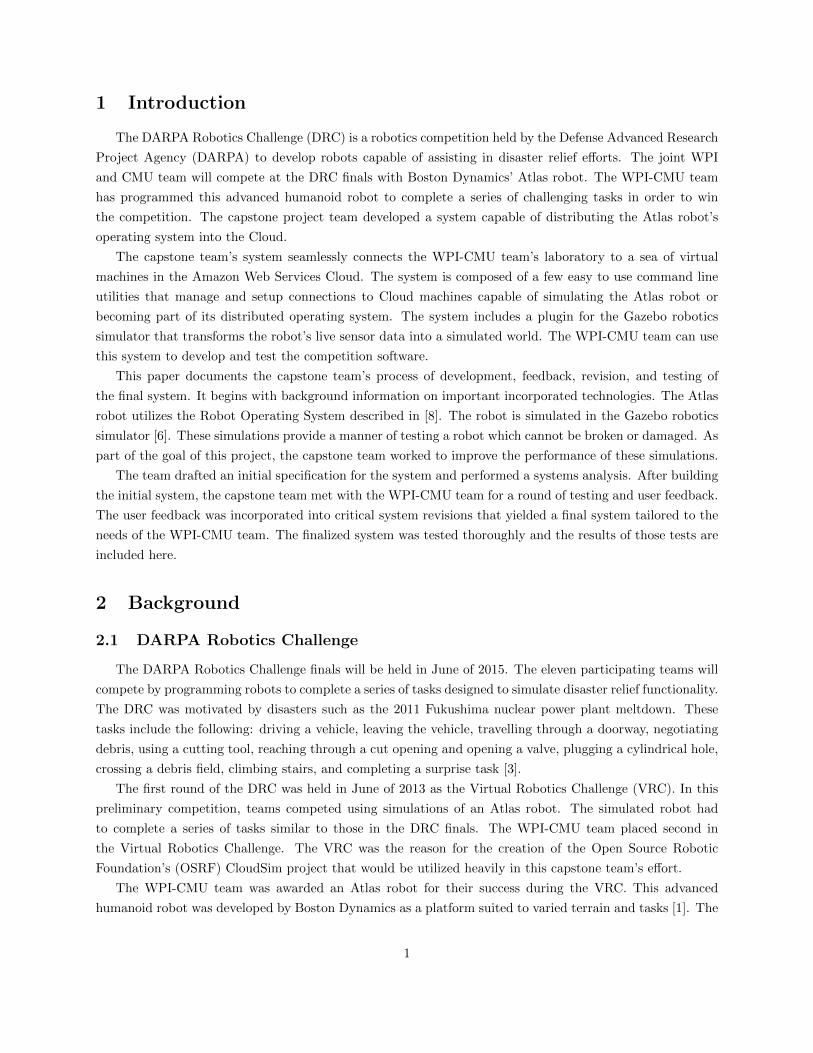
Figure 1: Boston Dynamics’ Atlas Robot
2

Figure 2: DRC Finals Simplified Communications Diagram [4]
Atlas robot is pictured in Figure 1.
Each team will have one hour to complete the whole set of tasks. The teams will be scored based on the
number of completed tasks and ties will be broken by finishing time. Each team will have two runs and will
be scored on the better run [3].
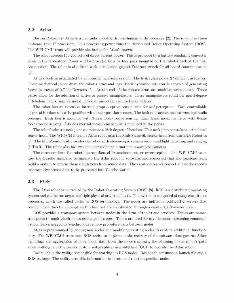
At the DRC finals, the WPI-CMU team will operate Atlas from the Operator Control Station (OCS)
computers. The robot will have a wireless connection to the field computer. The OCS has two wireless
links to the field computer: a unidirectional link and a bidirectional link. The unidirectional link will have
a bandwidth of 300 Mbits/sec. This link will transmit in one second bursts, with one to thirty second long
blackouts in between. The bidirectional link will have a bandwidth between 2,000 bits/sec and 9,600 bits/sec.
DARPA is also providing a Virtual Private Network (VPN) connection from the OCS to Cloud computing
resources with 50 Mbits/sec bandwidth [4]. Figure 2 shows an overview of the communications at the DRC
finals.
A test-bed event will be held in South Carolina in preparation for the DRC finals. The team will test the
Atlas robot in mock trial tasks. The WPI-CMU team will save all of the robot’s environmental perceptions.
The motivation is to use these recording to prepare for the final round of the competition. The capstone
team has created a system to model these perceptions in a Gazebo simulation.
The WPI-CMU team prepares for the DRC with accurate Gazebo simulations of each task. The team
moves from successful simulation of a task to testing the same code on the physical robot. This capstone
project allows the WPI-CMU team to leverage the distributed computing power available at the challenge
finals.
3
2.2 Atlas
Boston Dynamics’ Atlas is a hydraulic robot with near-human anthropometry [2]. The robot has three
on-board Intel i7 processors. This processing power runs the distributed Robot Operating System (ROS).
The WPI-CMU team will provide the brains for Atlas’s brawn.
The robot accepts 140-200 volts of direct current power. This is provided by a battery emulating converter
when in the laboratory. Power will be provided by a battery pack mounted on the robot’s back at the final
competition. The robot is also fitted with a dedicated gigabit Ethernet switch for off-board communication
[2].
Atlas’s body is articulated by an internal hydraulic system. The hydraulics power 27 different actuators.
These mechanical joints drive the robot’s arms and legs. Each hydraulic actuator is capable of generating
forces in excess of 2.7 kiloNewtons [2]. At the end of the robot’s arms are modular wrist plates. These
plates allow for the addition of active or passive manipulators. These manipulators could be: multi-degree
of freedom hands, simpler metal hooks, or any other required manipulator.
The robot has an extensive internal proprioceptive sensor suite for self-perception. Each controllable
degree of freedom senses its position with linear position sensors. The hydraulic actuators also sense hydraulic
pressure. Each foot is mounted with 3-axis force/torque sensing. Each hand mount is fitted with 6-axis
force/torque sensing. A 6-axis inertial measurement unit is mounted in the pelvis.
The robot’s electric neck joint constitutes a 28th degree of freedom. This neck joint controls an articulated
sensor head. The WPI-CMU team’s Atlas robot uses the MultiSense-SL sensor head from Carnegie Robotics
[2]. The MultiSense head provides the robot with stereoscopic camera vision and light detecting and ranging
(LIDAR). The robot also has two shoulder mounted situational-awareness cameras.
These sensors form the robot’s perceptions of its environment, or exteroception. The WPI-CMU team
uses the Gazebo simulator to simulate the Atlas robot in software, and requested that the capstone team
build a system to inform these simulations from sensor data. The capstone team’s project allows the robot’s
exteroceptive sensor data to be processed into Gazebo worlds.
2.3 ROS
The Atlas robot is controlled by the Robot Operating System (ROS) [8]. ROS is a distributed operating
system and can be run across multiple physical or virtual hosts. This system is composed of many constituent
processes, which are called nodes in ROS terminology. The nodes are individual XML-RPC servers that
communicate directly amongst each other, but are coordinated through a central ROS master node.
ROS provides a transport system between nodes in the form of topics and services. Topics are named
transports through which nodes exchange messages. Topics are used for asynchronous streaming communi-
cation. Services provide synchronous remote procedure calls between nodes.
Atlas is programmed by adding new nodes and modifying existing nodes to capture additional function-
ality. The WPI-CMU team uses ROS nodes to implement the entirety of the software that governs Atlas,
including: the aggregation of point cloud data from the robot’s sensors, the planning of the robot’s path
when walking, and the team’s customized graphical user interface (GUI) to operate the Atlas robot.
Roslaunch is the utility responsible for starting up ROS nodes. Roslaunch consumes a launch file and a
ROS package. The utility uses this information to locate and run the specified nodes.
4
ROS launch-files describe the collection of nodes to be launched in XML. Launch files coordinate nodes
across multiple machines. Users can specify nodes to be run remotely on another machine connected to the
same ROS master.
The WPI-CMU team coordinates the manipulations of the Atlas robot and field computer using cus-
tomized launch files. Some nodes run on the Operator Control Station. Usually these nodes are related
to client side tools like the WPI-CMU team’s customized graphical user interface for manipulating Atlas.
Other nodes run on the field computer or the robot itself.
2.4 Gazebo
Gazebo provides accurate physics simulations and visualizations of robots in dynamic environments
[5]. The Gazebo simulator runs as a ROS node. The Gazebo ROS API allows the manipulation of Gazebo
through ROS transports. The simulated robots have working sensors and cameras as well as realistic physical
characteristics [6]. The Gazebo client, gzclient, provides users with a graphical interface to a running
simulation. The Gazebo server, gzserver, computes real-time physics and runs simulated versions of the
robot’s sensors.
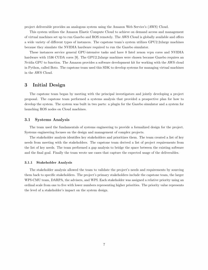
Gazebo uses the Simulation Description Format (SDF) to describe the robot and its environment. SDF
uses an XML schema to describe the appearance and physical characteristics of a model in the simulation
[7]. Gazebo provides for the insertion of SDF models into a running simulation.
1 <robot name="drc_skeleton">
2 <link name="l_clav">
3 <inertial >
4 <mass value="2.369" />
5 <origin xyz="0.014 0.058 0.029" rpy="0 -0 0" />
6 <inertia ixx="0.004" ixy="0.001" ixz="0" iyy="0.006" iyz="0" izz="0.007" />
7 </inertial >
8 <visual >
9 <origin xyz="0 0 0" rpy="1.04719755 0 0" />
10 <geometry >
11 <mesh filename="package :// atlas_description/meshes/l_clav.dae" scale="1 1 1" />
12 </geometry >
13 </visual >
14 <collision group="default">
15 <origin rpy="0 1.5707963267949 0" xyz="0 0.0697 0.0261"/>
16 <geometry >
17 <cylinder radius="0.045" length="0.1525"/>
18 </geometry >
19 </collision >
20 </link >
21 ...
22 </robot >
Listing 1: Part of the SDF used to describe the Atlas robot
Listing 1 demonstrates how the links and joints of a robot are described in SDF. The listing describes
the robot’s left clavicle and gives it physical and graphical properties, such as inertia and geometry. SDF
can be used to describe arbitrary robots and their environments in Gazebo.
5

Gazebo worlds are described in .world files, also written in SDF. Gazebo can dynamically load plugins
to modify the world or another aspect of the simulation. World files are loaded from ROS launch-files
through the Gazebo ROS API. A user can load a world file into Gazebo like so: roslaunch gazebo ros
empty world.launch This command will launch an empty Gazebo simulation.
The WPI-CMU team uses Gazebo simulations to assist in the operation of Atlas and in the development
effort in the lead up to the DRC. This means that the Gazebo simulator is key to the WPI-CMU team’s
operations both leading up to the finals and at the actual finals event.
Simulator performance is a limiting factor for the WPI-CMU team’s development velocity. Simulator
performance was degraded while performing the complicated tasks asked of the robot. The WPI-CMU team’s
customizations to the Gazebo user interface further degraded performance. A major goal of this project was
to ameliorate this issue.
The performance of a Gazebo simulation is measured by its real time factor. This statistic is defined assimulationtime
realtime . The real time factor of a simulation is a measure of how quickly the simulation is running
as compared to reality. High real time factors indicate good performance and low real time factors indicate
lackluster performance. By way of example, a simulation running at a one-half real time factor takes two
seconds to simulate one second of the robot’s operation. Conversely, a simulation running at at a real time
factor of two takes half a second to simulate one second of the robot’s operation. The WPI-CMU team
requested the ability to run Gazebo at a faster real time factor because simulator speed is a significant
bottleneck to development. The capstone team improved the performance of the simulator by moving it into
the Cloud.
2.5 CloudSim
CloudSim was developed by the Open Source Robotics Foundation to be used in the Virtual Robotics
Challenge. CloudSim uses Amazon Web Services to deploy virtual machines to run the Gazebo simulator.
CloudSim presents users with a web browser interface with which to manage simulation machines. The
OSRF also provides the user with a tool called gzweb. Gzweb lets the user view the simulation in their web
browser as if they were using the Gazebo client.
CloudSim gives the user the ability to use python scripts to affect a running simulation. CloudSim
gives the user the ability to establish a virtual private network connection between their computer and the
simulator machine in the Cloud. The user is additionally provided with the keys to connect to the simulator
machine via SSH. The capstone team utilized CloudSim as reference material for the team’s own systems.
2.6 Cloud Computing at the DRC
A major goal of the DRC is to advance Cloud robotics, and it is for this reason alone that the teams will
be provided with access to the Cloud at the DRC finals. Cloud computing is the utilization of remote servers
for computation and information storage. Cloud robotics is the use of these remote servers to improve the
performance of robots.
At the DRC finals, the WPI-CMU team will have a connection from the OCS to distributed processors
and storage in the Cloud. The capstone team’s project was to build a system that could take advantage of
these resources. The connection to these Cloud resources at the DRC finals will be through a VPN [4]. The
6
project deliverable provides an analogous system using the Amazon Web Service’s (AWS) Cloud.
This system utilizes the Amazon Elastic Compute Cloud to achieve on demand access and management
of virtual machines set up to run Gazebo and ROS remotely. The AWS Cloud is globally available and offers
a wide variety of different types of instances. The capstone team’s system utilizes GPU2.2xlarge machines
because they simulate the NVIDIA hardware required to run the Gazebo simulator.
These instances service general GPU-intensive tasks and have 8 Intel xenon vcpu cores and NVIDIA
hardware with 1536 CUDA cores [9]. The GPU2.2xlarge machines were chosen because Gazebo requires an
Nvidia GPU to function. The Amazon provides a software development kit for working with the AWS cloud
in Python, called Boto. The capstone team used this SDK to develop systems for managing virtual machines
in the AWS Cloud.
3 Initial Design
The capstone team began by meeting with the principal investigators and jointly developing a project
proposal. The capstone team performed a systems analysis that provided a prospective plan for how to
develop the system. The system was built in two parts: a plugin for the Gazebo simulator and a system for
launching ROS nodes on Cloud machines.
3.1 Systems Analysis
The team used the fundamentals of systems engineering to provide a formalized design for the project.
Systems engineering focuses on the design and management of complex projects.
The stakeholder analysis identifies key stakeholders and prioritizes them. The team created a list of key
needs from meeting with the stakeholders. The capstone team derived a list of project requirements from
the list of key needs. The team performed a gap analysis to bridge the space between the existing software
and the final goal. Finally the team wrote use cases that capture the expected usage of the deliverables.
3.1.1 Stakeholder Analysis
The stakeholder analysis allowed the team to validate the project’s needs and requirements by sourcing
them back to specific stakeholders. The project’s primary stakeholders include the capstone team, the larger
WPI-CMU team, DARPA, the advisers, and WPI. Each stakeholder was assigned a relative priority using an
ordinal scale from one to five with lower numbers representing higher priorities. The priority value represents
the level of a stakeholder’s impact on the system design.
7

ID Title Description Role Priority ContactSH.01 DRC Team
WPI-CMUTeam members who workon Atlas
Programming the robot;testing; wrangling; partic-ipation in meetings
1 email alias,weeklymeetings
SH.02 Advisors Professors Padir and Gen-nert
Advising the team; provid-ing critical oversight, acu-men and strategy; facili-tates use of lab equipment,resource acquisition, etc.;responsible for grading
2 e-mail,weeklymeetings,telephone
SH.03 DARPA Defense Advanced Re-search Projects Agency
Managing the competition;declaration of the rulesof the competition; poten-tial government use of thistechnology
5 One-waycontact; re-ceive newsfrom teamleaders.
SH.04 WPI One of two schools on theDRC team, and the schoolthe capstone team mem-bers are from
Public relations, prizemoney, and advertise-ment tied to DRC teamperformance
5 Proxy: Ad-visors
SH.05 CapstoneTeam
The MQP team buildingthe system. Members ofSH.01
Grades and experience; de-signing, building, and test-ing the system; assistingthe team where necessaryon non-MQP related taskssuch as wrangling the robot
4 group orpersonal e-mail, dailyand ad-hocmeetings
Table 1: The Stakeholder table describes each stakeholder and prioritizes them, with 1 being highest priorityand 5 being the lowest.
The WPI-CMU Team was given the maximum priority of one because WPI-CMU is the stakeholder who
directly consumes the capstone team’s deliverables. The project’s advisers were given a priority of two to
show their high level of impact on the project’s goals and design. A priority of four was given to the capstone
team because they are subservient to the other stakeholders. WPI and DARPA were assigned priorities of
five because the other stakeholders have much more immediate impact on the project.
3.1.2 Key Needs Analysis
The team’s key needs were traced to specific stakeholders. See Table 2, which assigns each need an
identifying ID. The capstone team described, categorized, and traced each key need.
8
ID Need Stakeholder TraceN.01 The system should provide for the running of a simulation in a Cloud
environment.SH.01, SH.02, SH.03,SH.04, SH.05
N.02 The system should be able to map the robot’s perceptions into thesimulation.
SH.01, SH.05
N.03 The system should aid the WPI-CMU team’s development process. SH.01, SH.05N.04 The system should be accessible to the WPI-CMU team and should
be simple to use.SH.01, SH.05
Table 2: The Key Needs table presents the project’s needs in the order that they were addressed by thecapstone team. Starting with the ability to move simulations into the Cloud, each need builds upon theprevious need. A successful implementation needed to satisfy all of these needs.
3.1.3 Gap Analysis
The gap between the initial system and the desired outcome informed design and process decisions. The
first need identified was to build and set up a Cloud simulation environment. The existing OSRF project,
CloudSim, was a strong candidate for fulfilling this need. CloudSim is capable of fully simulating Atlas and
exposes browser-side tools for interacting with Gazebo.
The capstone team rejected CloudSim because it was not able to meet the specific needs of the WPI-CMU
team. The WPI-CMU team’s customized software is incompatible with the latest stable release of CloudSim.
The capstone team would begin by using CloudSim for managing the Cloud machines, but would eventually
build its own command line tools for working with the machines themselves.
The second need was to map the robot’s perceptions into a simulation. The WPI-CMU team can take the
sum of the robot’s perceptions and store them in an occupancy map. However, there did not yet exist a way
to use that occupancy map to inform the obstacles within a simulated environment. Gazebo’s functionality
needed to be extended to meet this need. Gazebo provides for extending its features with user-defined
plugins. This method was chosen for mapping the robot’s perceptions into the simulation.
The third and fourth needs were the most important because they ensure usability. The system was
made accessible and easy to use by tailoring it to the specific usage of the WPI-CMU team. The capstone
team met with members of the WPI-CMU team and based the interface of the deliverable around the team
members’ expected usage.
3.1.4 Requirements
The capstone team used the key needs to derive testable and verifiable requirements for the project. Table
3 below describes each requirement and gives each an identifier, a category, and a priority. The priorities are
once again ordinal from one to five with one being the highest priority. In addition, each requirement was
validated by tying it back to the relevant stakeholders and needs from Table 2. Requirements have three
categories: design, performance, and technology. Design requirements inform the design of the system and
its interfaces. Performance requirements constrain the performance of the system. Technology requirements
represent technologies that the team is required to use.
9
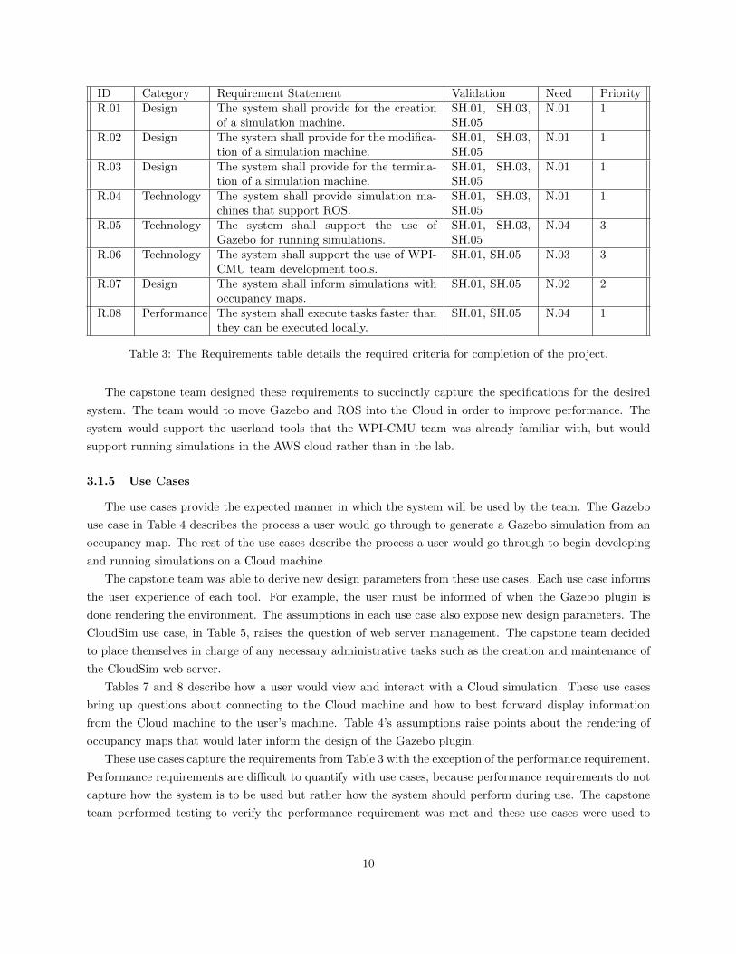
ID Category Requirement Statement Validation Need PriorityR.01 Design The system shall provide for the creation
of a simulation machine.SH.01, SH.03,SH.05
N.01 1
R.02 Design The system shall provide for the modifica-tion of a simulation machine.
SH.01, SH.03,SH.05
N.01 1
R.03 Design The system shall provide for the termina-tion of a simulation machine.
SH.01, SH.03,SH.05
N.01 1
R.04 Technology The system shall provide simulation ma-chines that support ROS.
SH.01, SH.03,SH.05
N.01 1
R.05 Technology The system shall support the use ofGazebo for running simulations.
SH.01, SH.03,SH.05
N.04 3
R.06 Technology The system shall support the use of WPI-CMU team development tools.
SH.01, SH.05 N.03 3
R.07 Design The system shall inform simulations withoccupancy maps.
SH.01, SH.05 N.02 2
R.08 Performance The system shall execute tasks faster thanthey can be executed locally.
SH.01, SH.05 N.04 1
Table 3: The Requirements table details the required criteria for completion of the project.
The capstone team designed these requirements to succinctly capture the specifications for the desired
system. The team would to move Gazebo and ROS into the Cloud in order to improve performance. The
system would support the userland tools that the WPI-CMU team was already familiar with, but would
support running simulations in the AWS cloud rather than in the lab.
3.1.5 Use Cases
The use cases provide the expected manner in which the system will be used by the team. The Gazebo
use case in Table 4 describes the process a user would go through to generate a Gazebo simulation from an
occupancy map. The rest of the use cases describe the process a user would go through to begin developing
and running simulations on a Cloud machine.
The capstone team was able to derive new design parameters from these use cases. Each use case informs
the user experience of each tool. For example, the user must be informed of when the Gazebo plugin is
done rendering the environment. The assumptions in each use case also expose new design parameters. The
CloudSim use case, in Table 5, raises the question of web server management. The capstone team decided
to place themselves in charge of any necessary administrative tasks such as the creation and maintenance of
the CloudSim web server.
Tables 7 and 8 describe how a user would view and interact with a Cloud simulation. These use cases
bring up questions about connecting to the Cloud machine and how to best forward display information
from the Cloud machine to the user’s machine. Table 4’s assumptions raise points about the rendering of
occupancy maps that would later inform the design of the Gazebo plugin.
These use cases capture the requirements from Table 3 with the exception of the performance requirement.
Performance requirements are difficult to quantify with use cases, because performance requirements do not
capture how the system is to be used but rather how the system should perform during use. The capstone
team performed testing to verify the performance requirement was met and these use cases were used to
10
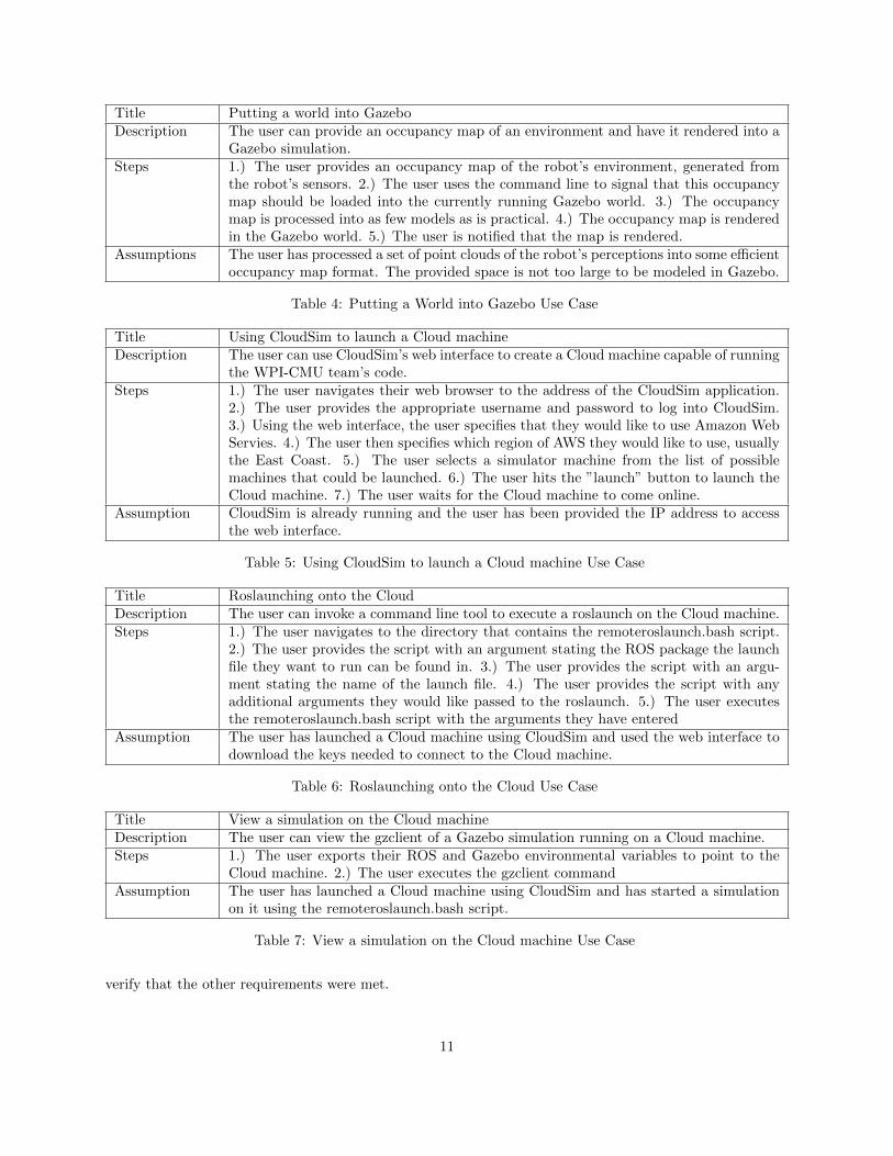
Title Putting a world into GazeboDescription The user can provide an occupancy map of an environment and have it rendered into a
Gazebo simulation.Steps 1.) The user provides an occupancy map of the robot’s environment, generated from
the robot’s sensors. 2.) The user uses the command line to signal that this occupancymap should be loaded into the currently running Gazebo world. 3.) The occupancymap is processed into as few models as is practical. 4.) The occupancy map is renderedin the Gazebo world. 5.) The user is notified that the map is rendered.
Assumptions The user has processed a set of point clouds of the robot’s perceptions into some efficientoccupancy map format. The provided space is not too large to be modeled in Gazebo.
Table 4: Putting a World into Gazebo Use Case
Title Using CloudSim to launch a Cloud machineDescription The user can use CloudSim’s web interface to create a Cloud machine capable of running
the WPI-CMU team’s code.Steps 1.) The user navigates their web browser to the address of the CloudSim application.
2.) The user provides the appropriate username and password to log into CloudSim.3.) Using the web interface, the user specifies that they would like to use Amazon WebServies. 4.) The user then specifies which region of AWS they would like to use, usuallythe East Coast. 5.) The user selects a simulator machine from the list of possiblemachines that could be launched. 6.) The user hits the ”launch” button to launch theCloud machine. 7.) The user waits for the Cloud machine to come online.
Assumption CloudSim is already running and the user has been provided the IP address to accessthe web interface.
Table 5: Using CloudSim to launch a Cloud machine Use Case
Title Roslaunching onto the CloudDescription The user can invoke a command line tool to execute a roslaunch on the Cloud machine.Steps 1.) The user navigates to the directory that contains the remoteroslaunch.bash script.
2.) The user provides the script with an argument stating the ROS package the launchfile they want to run can be found in. 3.) The user provides the script with an argu-ment stating the name of the launch file. 4.) The user provides the script with anyadditional arguments they would like passed to the roslaunch. 5.) The user executesthe remoteroslaunch.bash script with the arguments they have entered
Assumption The user has launched a Cloud machine using CloudSim and used the web interface todownload the keys needed to connect to the Cloud machine.
Table 6: Roslaunching onto the Cloud Use Case
Title View a simulation on the Cloud machineDescription The user can view the gzclient of a Gazebo simulation running on a Cloud machine.Steps 1.) The user exports their ROS and Gazebo environmental variables to point to the
Cloud machine. 2.) The user executes the gzclient commandAssumption The user has launched a Cloud machine using CloudSim and has started a simulation
on it using the remoteroslaunch.bash script.
Table 7: View a simulation on the Cloud machine Use Case
verify that the other requirements were met.
11
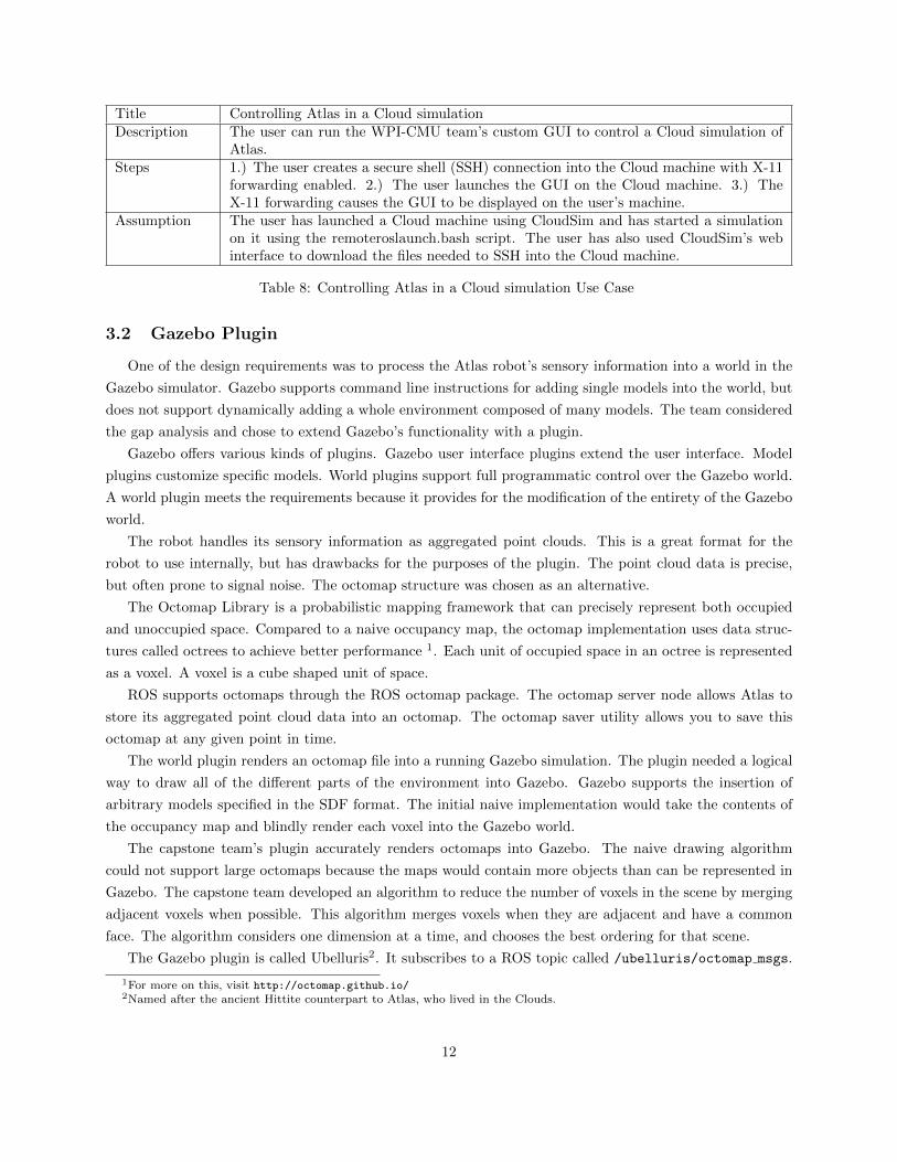
Title Controlling Atlas in a Cloud simulationDescription The user can run the WPI-CMU team’s custom GUI to control a Cloud simulation of
Atlas.Steps 1.) The user creates a secure shell (SSH) connection into the Cloud machine with X-11
forwarding enabled. 2.) The user launches the GUI on the Cloud machine. 3.) TheX-11 forwarding causes the GUI to be displayed on the user’s machine.
Assumption The user has launched a Cloud machine using CloudSim and has started a simulationon it using the remoteroslaunch.bash script. The user has also used CloudSim’s webinterface to download the files needed to SSH into the Cloud machine.
Table 8: Controlling Atlas in a Cloud simulation Use Case
3.2 Gazebo Plugin
One of the design requirements was to process the Atlas robot’s sensory information into a world in the
Gazebo simulator. Gazebo supports command line instructions for adding single models into the world, but
does not support dynamically adding a whole environment composed of many models. The team considered
the gap analysis and chose to extend Gazebo’s functionality with a plugin.
Gazebo offers various kinds of plugins. Gazebo user interface plugins extend the user interface. Model
plugins customize specific models. World plugins support full programmatic control over the Gazebo world.
A world plugin meets the requirements because it provides for the modification of the entirety of the Gazebo
world.
The robot handles its sensory information as aggregated point clouds. This is a great format for the
robot to use internally, but has drawbacks for the purposes of the plugin. The point cloud data is precise,
but often prone to signal noise. The octomap structure was chosen as an alternative.
The Octomap Library is a probabilistic mapping framework that can precisely represent both occupied
and unoccupied space. Compared to a naive occupancy map, the octomap implementation uses data struc-
tures called octrees to achieve better performance 1. Each unit of occupied space in an octree is represented
as a voxel. A voxel is a cube shaped unit of space.
ROS supports octomaps through the ROS octomap package. The octomap server node allows Atlas to
store its aggregated point cloud data into an octomap. The octomap saver utility allows you to save this
octomap at any given point in time.
The world plugin renders an octomap file into a running Gazebo simulation. The plugin needed a logical
way to draw all of the different parts of the environment into Gazebo. Gazebo supports the insertion of
arbitrary models specified in the SDF format. The initial naive implementation would take the contents of
the occupancy map and blindly render each voxel into the Gazebo world.
The capstone team’s plugin accurately renders octomaps into Gazebo. The naive drawing algorithm
could not support large octomaps because the maps would contain more objects than can be represented in
Gazebo. The capstone team developed an algorithm to reduce the number of voxels in the scene by merging
adjacent voxels when possible. This algorithm merges voxels when they are adjacent and have a common
face. The algorithm considers one dimension at a time, and chooses the best ordering for that scene.
The Gazebo plugin is called Ubelluris2. It subscribes to a ROS topic called /ubelluris/octomap msgs.
1For more on this, visit http://octomap.github.io/2Named after the ancient Hittite counterpart to Atlas, who lived in the Clouds.
12

The user can direct the plugin to a map file by publishing to this topic. To do so, the user would execute:
~: rostopic pub /ubelluris/octomap_msgs std_msgs/String mapfile.bt
The plugin will then load the map file and render it into Gazebo as quickly as possible.
3.3 Running Ros & Gazebo in the Cloud
A design requirement was to launch simulations onto Cloud machines that were capable of supporting
the entirety of the WPI-CMU team’s development tools and dependencies. These development tools include
Gazebo, rviz the robotics visualizer, and the team’s customized graphical user interface for interacting with
the robot. One existing system to launch Gazebo simulations in the Cloud is the Open Source Robotics
Foundation’s CloudSim project.
CloudSim allows a user to interact with a website to manage and manipulate cloud machines as well as
use the Gazebo simulator on said machines. The OSRF has a gzweb project that CloudSim uses to allow
users to visualize Gazebo simulations in the browser. This allows a machine that could not otherwise run
Gazebo to interact with Gazebo simulations. Gzweb was perfect for the VRC but is incompatible with the
WPI-CMU team’s usage of Gazebo and related tools.
The initial design of the system was to use CloudSim to launch and manage Cloud machines. This design
also gave the user a script, called remoteroslaunch.bash, to run ROS nodes on these Cloud machines. This
system could run Gazebo simulations, or just ROS nodes, on the virtual machines maintained by CloudSim.
This initial system was adequate, but not perfect. The capstone team turned to user feedback to look for a
way to improve the system.
4 User Feedback
The capstone team presented the initial design and deliverables to the wider WPI-CMU team. Members
of the WPI-CMU team ran the initial Cloud simulation system and responded with feedback on its operations
and performance. The initial demonstration of Cloud simulation highlighted some areas of improvement for
the overall system. The capstone team used this to derive a list of additional requirements for the overall
system and to generate additional use cases.
CloudSim would have to be removed from the system. The WPI-CMU team needed fast access to the
Cloud but CloudSim took 5-10 minutes to launch a machine. Also, the Gzweb based user interface precluded
any integration with the WPI-CMU team’s customized GUI. Additionally, CloudSim became significantly
out-of-date in terms of supported ROS and Gazebo packages. Over time more and more work was required
to use CloudSim in the manner initially adopted by the capstone team.
The WPI-CMU team required a Cloud machine management infrastructure too different from CloudSim.
CloudSim had an appropriate user interface for the VRC, but not the DRC finals. The capstone team
decided to replace the usage of CloudSim with a custom utility for launching and managing virtual machines
in the AWS Cloud. The capstone team designed and built a system for managing Cloud simulators from the
WPI-CMU team’s lab. This system takes the form of a python script called cloudmanager.py
Also, the capstone team identified the need for a system daemon to monitor the Cloud machines and to
bring down any that went haywire or were left unattended. This daemon would be crucial because machines
13
running overtime would be an unnecessary drain on the team’s financial resources.
The WPI-CMU team’s customized tools and interfaces worked poorly with the initial Cloud system. In
the initial design, the WPI-CMU team’s customized GUI would be X11 forwarded from the Cloud machine.
This resulted in lackluster performance due to the network latency between the Cloud and the laboratory
where the tests were conducted. The capstone team worked with the wider WPI-CMU team to develop a
solution to this problem. The capstone team used some of the WPI-CMU team’s existing ROS nodes to
connect a local GUI to the cloud machine over a TCP/UDP tunnel.
Additionally, tab completion would be added to the system to make it more accessible to users. ROS
allows users to use tab completion when executing commands to enter arguments, such as ROS packages and
launch files. The cloud management software was designed to utilize ROS’s package structure. The capstone
team integrated bash completion into its cloudmanager.py software to allow for the same ease of use by an
end user.
The WPI-CMU team had begun using a proprietary optimization library called Gurobi for trajectory
optimization. This offered powerful new capabilities both to simulations and to real ROS systems connected
to the robot.
The WPI-CMU team uses Gurobi’s free academic license to register their copies of Gurobi. This method
requires that each machine be uniquely identified by a tuple of mac address, hostname, and internet protcol
address. This process is not intrusive in normal usage of the Gurobi library. The user merely logs into
the Gurobi website with the appropriate academic email address. This registration method requires that
each licensed machine be within the WPI campus network to become licensed. This presented a problem
for running the WPI-CMU team’s code on Cloud machines. Each Cloud machine would have a different
tuple of identifying information. Additionally, the machine would be from outside of the wpi.edu domain
and therefore not registrable with a free academic license. The capstone team created another program to
automate the process in order to overcome this limitation.
5 Final Design
The user feedback was used to design a finalized system. The capstone team was eventually able to
perform all the upgrades necessitated by the user feedback. It was challenging to surmount the issues faced
by the initial system, but the final system incorporates all required functions identified in user feedback.
This final system allows the WPI-CMU team to control a whole host of simulated machines in the Amazon
Cloud. These machines are dynamically available in only a few minutes. A user can connect to a Cloud
machine to speed up the performance of their Gazebo simulation or to run remote ROS nodes. The system
supports either local or remote ROS masters.
The capstone team designed a daemon that monitors this Cloud lab and terminates long running machines
that have been forgotten. The development of this daemon utilized the same Boto SDK the capstone team
used to develop the prior utility for managing individual Cloud simulator machines. The cost of running
virtual machines is quite modest and the daemon ensures that money is never wasted by letting machines
run out of control. This daemon can run on a laboratory machine already in the WPI-CMU team’s lab, on
a host outside of the lab, or within the Cloud.
An important challenge to overcome was the clunky licensing process for the Gurobi dependency that
14

would not work in the Cloud. This was not an issue in the traditional lab setup, but became quite the problem
for the capstone team’s virtual lab in the Cloud. Ultimately the capstone team ended up automating this
process as a short program, called gurobilicense.py.
Additionally, the capstone team updated the userland tools to support bash completion. This update
makes the custom WPI-CMU Cloud utilities work seamlessly with existing ROS and Gazebo tools. Also, the
capstone team made updates to support the customized graphical interface used by the WPI-CMU team.
5.1 Updated Requirements
After receiving user feedback, the requirements for the Cloud management utility needed to be updated.
The existing requirements derived during the capstone team’s initial systems analysis still needed to be met.
However, some of these requirements had to be expanded upon to capture the users’ feedback. New require-
ments also had to be added, and some of the existing requirements were combined. The new requirements
for the Cloud management utility can be found in Table 9.
ID Category Requirement Statement Validation Need PriorityR.01 Design The system shall provide for the creation
of a simulation machine.SH.01, SH.03,SH.05
N.01 1
R.02 Design The system shall provide for the modifi-cation of a simulation machine. Modifica-tions to simulation machines can be savedfor later use.
SH.01, SH.03,SH.05
N.01 1
R.03 Design The system shall provide for the termina-tion of a simulation machine. The systemshall provide a daemon to terminate ma-chines that are inactive.
SH.01, SH.03,SH.05
N.01 1
R.04 Technology The system shall provide simulation ma-chines that support ROS, Gazebo, and theteam’s development tools.
SH.01, SH.03,SH.05
N.01 1
R.05 Technology The system shall allow the Cloud machinesto easily register Gurobi.
SH.01, SH.03,SH.05
N.01 1
R.06 Performance The system shall allow the team’s devel-opment tools to be used without latency.
SH.01, SH.05 N.02 2
R.07 Performance The system shall execute tasks faster thanthey can be executed locally.
SH.01, SH.05 N.04 1
Table 9: The Updated Requirements table details the new requirements for the Cloud management system.
The capstone team updated the first three design requirements to reflect the new utilities for managing
the virtual machines. The fourth requirement is largely conserved from the earlier requirements list. The fifth
requirement captures the need to properly license the Gurobi library from the Cloud. The sixth requirement
reflects the changed approach for running the WPI-CMU team’s client-side tools. Formerly these were X11
forwarded at great expense but are now run directly on the lab computer and are merely connected to the
Cloud simulator machine. The performance requirement, number seven, has remained unchanged.
15

5.2 Updated Use Cases
The finalized system design prompted a revision of the use cases. The capstone team developed additional
use cases to capture the specific functionality that was added in the final revision of the system. The original
use cases still apply to the final system but have been omitted for brevity.
Title Connecting to the CloudDescription The user can invoke a command line tool to get secure shell connectivity to a Gazebo
simulation instance in the Cloud.Steps 1.) The user runs a command line utility. 2.) The user provides appropriate credentials
to the utility. 3.) The user is now in a VPN with the Cloud machine. 4.) The useris provided with a script for logging into the Cloud machine. 5.) The user is providedwith a script that will launch arbitrary ROS nodes onto the machine.
Assumption The user has credentials for the Cloud.
Table 10: Connecting to the Cloud Use Case
The purpose of this use case is to capture the new Cloud management utility that users can use to
manage virtual machines in the Amazon Cloud. This utility replaces the capstone team’s prior usage of the
CloudSim project.
Title A daemon to manage the Cloud MachinesDescription The user can run a daemon to monitor the Cloud machines and turn off long running
machines.Steps 1.) The user starts a daemon from the command line. 2.) The user can view a log of
the daemons output. 3.) The daemon shuts down any machines that are accidentallyleft running.
Assumption The user has credentials for the Cloud. The daemon has these credentials as well.
Table 11: A daemon to manage the Cloud Machines Use Case
This use case captures the new daemon that was added to the cloud management system. The daemon
terminates long running machines to save the WPI-CMU team money.
Title Registering Gurobi on a Cloud machineDescription The user can register Gurobi on their Cloud machine.Steps 1.) The user creates an SSH connection into the Cloud machine. 2.) The user runs
the script gurobilicense.py. 3.) The user provides the script with their credentials forthe Gurobi website and WPI’s proxy. 4.) The script register’s Gurobi on the Cloudmachine
Assumption The user has launched and has the credentials for a Cloud.
Table 12: Registering Gurobi on a Cloud machine Use Case
This use case represents an important step towards automating the registration of critical WPI-CMU
dependencies. The capstone team automated this process in a small program that takes in a user’s credentials
and uses them to license Gurobi with a free academic license.
16

5.3 Utility for Management of Cloud Machines
CloudSim had to be replaced, but the ability to manage virtual machines had to be retained. CloudSim
was replaced with a python script, called cloudmanager.py to manage Cloud machines. It achieves everything
needed of CloudSim, and is not burdened with the other features supported by the OSRF’s CloudSim project.
Components of CloudSim were salvaged wherever possible to expedite the development process.
The capstone team’s program, like CloudSim, used Amazon’s Boto SDK to interact with Amazon’s Cloud.
The script uses Boto to provide the user with a list of running Cloud machines. It then gives the user the
option to either connect to an already running Cloud machine, or to launch a new one. Usage is as follows:
~: sudo python cloudmanager.py
Welcome! Here are the already-running machines:
54.148.21.20 is running master 2-15
Enter target IP address to connect to a running instance, or enter NEW for a new machine.
>>
If the user launches a new machine, they are given a list of machine images to launch.
>>NEW
Would you like to use the default machine image, or load a saved one?
Enter an image name to use a saved image, or enter DEFAULT for the default image.
default_image
master 2-15
>>
After the user has connected to their machine, the script establishes a secure VPN connection between the
user’s machine and the one in the Cloud. The script lastly waits for the user to instruct it to shut down the
Cloud machine or to save an image of the machine. Here is the terminal output of setting up the VPN with
the prompt for the user’s next command.
>>master 2-15
launching machine, this can take a few minutes...
Setting up VPN to IP 52.0.149.216
The authenticity of host ’52.0.149.216 (52.0.149.216)’ can’t be established.
ECDSA key fingerprint is 7c:5a:29:9e:ef:44:55:20:7e:57:e6:db:9b:d3:3d.
Are you sure you want to continue connecting (yes/no)? yes
Warning: Permanently added ’52.0.149.216’ (ECDSA) to the list of known hosts.
openvpn.key 100\% 636 0.6KB/s 00:01
Killing other openvpn connections...
VPN ready. To kill it:
sudo killall openvpn
connected to machine running at IP 52.0.149.216
hostname: ec2-52-0-149-216.compute-1.amazonaws.com
to save an image of the machine, enter save_ami desired_image_name
to terminate the instance, enter terminate
17
to exit, enter exit
>>
Users can choose to save machine images with arbitrary names. These images can be loaded the next time
a user launches a Cloud machine. This allows users to save any modifications they make to their machines
to be loaded in the future.
>>save_ami new machine image name
saving an image, the machine will not be usable while this happens.
Cloudmanager.py provides users with the ability to SSH into the Cloud machines. It provides this
functionality through sshsim.bash. This bash script, borrowed from CloudSim, connects users to their
virtual machine using the previously shared SSH keys.
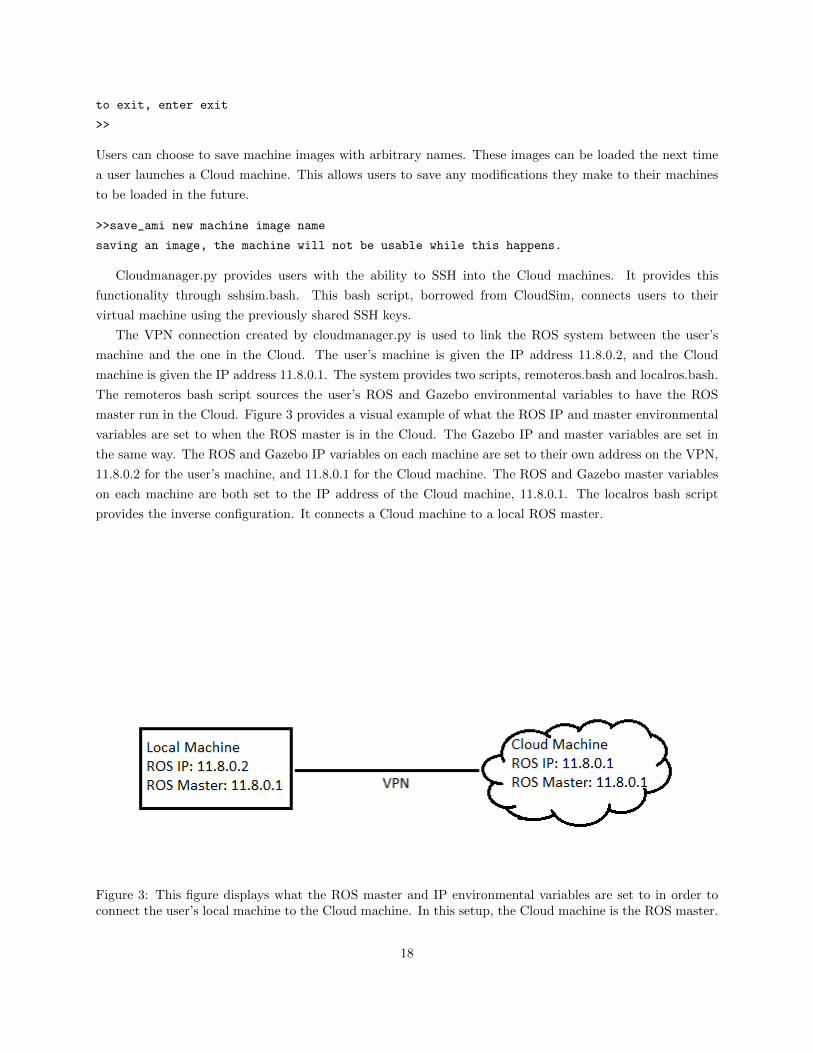
The VPN connection created by cloudmanager.py is used to link the ROS system between the user’s
machine and the one in the Cloud. The user’s machine is given the IP address 11.8.0.2, and the Cloud
machine is given the IP address 11.8.0.1. The system provides two scripts, remoteros.bash and localros.bash.
The remoteros bash script sources the user’s ROS and Gazebo environmental variables to have the ROS
master run in the Cloud. Figure 3 provides a visual example of what the ROS IP and master environmental
variables are set to when the ROS master is in the Cloud. The Gazebo IP and master variables are set in
the same way. The ROS and Gazebo IP variables on each machine are set to their own address on the VPN,
11.8.0.2 for the user’s machine, and 11.8.0.1 for the Cloud machine. The ROS and Gazebo master variables
on each machine are both set to the IP address of the Cloud machine, 11.8.0.1. The localros bash script
provides the inverse configuration. It connects a Cloud machine to a local ROS master.
Figure 3: This figure displays what the ROS master and IP environmental variables are set to in order toconnect the user’s local machine to the Cloud machine. In this setup, the Cloud machine is the ROS master.
18

The remoteroslaunch.bash script is used to launch ROS nodes on the Cloud machine, as it was in the
initial design. This script synchronizes the user’s workspace to match the one in the Cloud. This was done
in order to keep the workflow of using the Cloud as close as possible to the team’s original workflow. The
script accomplishes this sychronization by using the rsync utility. The script then has the Cloud machine
set up its environmental variables appropriately, as shown in Figure 3.
The remoteroslaunch.bash script lastly executes the roslaunch command on the Cloud machine, using
the arguments provided by the user. This bash script accepts arguments in the same manner as roslaunch.
For example, to roslaunch Atlas in a blank world with the argument for the model version to be four, one
would execute:
~: roslaunch wrecs_simulator_v4_launch atlas_blank.launch model_args:="_v4".
Similarly, to do this with remoteroslaunch.bash one would execute:
~: ./remoteroslaunch.bash wrecs_simulator_v4_launch atlas_blank.launch model_args:="_v4".
In order to have remoteroslaunch.bash work identically to the roslaunch command, the capstone team gave
it the ability to tab complete its arguments.
The remoteroslaunch.bash will only start the gzserver component of Gazebo when the client is not
required. This prevents the Cloud machine from having to process the display of Gazebo, which improves
the simulator’s performance. The display can be viewed on the user’s machine by running the gzclient.
Sourcing remoteros.bash allows the user to connect the local gzclient to the gzserver running on the Cloud
machine. This allows the user to use gzclient to interact with a Gazebo simulation running in the Cloud.
The capstone team initially explored running the DRC team’s customized GUI in the Cloud. The initial
design used X11 to forward the GUI to the local machine. However, this method caused noticeable delay in
the user interface due to the network latency between the local machine and the Cloud. To fix this problem,
the capstone team redesigned the system to use the team’s existing ROS node to create a TCP/UDP relay
from the Cloud machine to the user’s. This is the same relaying method that allows telecommuting members
of the WPI-CMU team to remotely test the actual Atlas robot. The user runs the GUI locally, using the
TCP/UDP relay to send inputs and changes in display between the two machines. This setup allowed the
customized GUI to run smoothly on the user’s machine while connected to a Cloud simulation.
5.4 System Daemon for Management of the Cloud Lab
The capstone team designed and implemented a daemon to manage the Cloud machines autonomously.
This system daemon is a linux program, clouddaemon.py, that runs in the background and monitors the
WPI-CMU team’s AWS account. The daemon is programmed to shut down any long running virtual
machines.
The daemon tracks if there are any machines currently running in the Cloud. If there are no machines
running, the daemon wakes every two hours to check on the lab. If machines are running, the daemon
shuts down any machines that have been running for longer than three hours. The daemon calculates the
run-time of every running machine when it wakes up. If there are still machines running, the daemon will
wake again at the time when the first machine’s runtime totals three hours. When the daemon wakes up, it
will again choose which machines to terminate and when it should again awaken. This process repeats until
the daemon receives the signal to terminate.
19
5.5 Gurobi & Other User Interface Updates
The capstone team worked to overcome incompatibility with the Gurobi library dependency. The Gurobi
library had become a major requirement for the WPI-CMU team’s DRC tasks. Gurobi is a high performance
optimization library used for linear programming, quadratic and quadratically constrained programming, and
mixed integer programming. The WPI-CMU team uses this library for trajectory optimization.
This was a major problem for the capstone team because the library would have to be registered every
time a simulator machine was loaded - even if the machine-image had been used before and had previously
registered Gurobi. This contrasts with the WPI-CMU team’s lab computers, which have statically defined
identifying credentials like IP and MAC addresses and so only need to be registered once. Additionally,
academic licenses for Gurobi are only valid within an academic domain. The virtual machines in the Cloud
would have to appear to be within the wpi.edu private network in order to be registered.
The capstone team quickly overcame this by learning how to license Gurobi through X11 forwarded
browser sessions that utilized the WPI campus VPN. The configuration for this was moderately complex,
and the performance of the X11 forwarded browser was often lack luster and frustrating to the user. It would
have been unreasonable to expect every user of the system to go through this process every time they want
to use a virtual machine.
The capstone team overcame these problems by automating the licensing process. The solution takes the
form of a small python program, gurobilicense.py. This program takes credentials from the user and uses
them to register the Gurobi library for that computer.
The program uses the python ”requests” module to interact with the Gurobi licensing and authentication
servers. Importantly, the packets involved are routed through WPI’s student proxy sever with an opensource
utility called ”proxychains”. This utility routes the requests through proxy.wpi.edu using the given user’s
WPI credentials. This proxy server is enough to allow Gurobi to be licensed using a free academic license,
even though it is running on a machine in the AWS cloud that would normally be outside of the wpi.edu
domain.
This process was incorporated into the cloud machine management software so that machines would
automatically be equipped with registered copies of the Gurobi library. Some members of the WPI-CMU
team were interested in running simulations on their own computers and needed to license Gurobi off of
campus. This utility was provided to allow this process to be as quick and painless as possible. The terminal
inputs and outputs of running the utility are shown below.
~: ./gurobilicense.py [email protected] gurobipassforjlmegin jlmegin wpipassforjlmegin
Gurobi liscene key: b6885e2b-ac21-1d85-4ac9-54f38cf096e
ProxyChains-3.1 (http://proxychains.sf.net)
Gurobi license key lcient (version 6.0.0)
Copyright (c) 2014, Gurobi Optimization, Inc.
--------------------------------
Contacting Gurobi key server...
--------------------------------
20

|DNS-request| apps.gurobi.com
|S-chain|-<>-130.215.36.61:8080-<>-130.215.36.61:8080-<><>-4.2.2.2:53-<><>-OK
|DNS-response| apps.gurobi.com is 108.116.123.68
|S-chain|-<>-130.215.36.61:8080-<>-140.215.36.61:8080-<><>-108.166.123.68:80-<><>-OK
Key for license ID 84751 was successfully retrieved.
License expires at the end of the day on 2016-02-29.
---------------------
Saving license key...
---------------------
In which directory would you like to store the Gurobi license key file?
[hit Enter to store it in /home/ubuntu]:
--> License key saved to file ’/home/ubuntu/gurobi.lic’.
6 Evaluation
The capstone team designed tests to verify that the system worked and met the design requirements.
The Cloud management utility was tested to determine in-simulator performance and the amount of time
it takes to launch a virtual machine. The latter was accomplished by using the utility to launch machines
onto Amazon’s Cloud and measuring how long it took for these machines to start up. The performance of
these Cloud machines was then compared to the computers in the WPI-CMU lab. The capstone team ran
the same simulations on both local, and cloud based machines and compared the performance of both.
The Gazebo plugin was tested to verify its ability to quickly and accurately render worlds into Gazebo
from the robot’s sensory information. The plugin was tested to see if it could correctly render a variety of
sample octomaps into a Gazebo simulation. The plugin was also tested with an octomap generated by a
simulated Atlas. These tests confirmed the accuracy of the capstone team’s plugin.
The exhaustive system tests performed by the capstone team verified each requirement identified in the
systems analysis. These tests are based closely on the use cases that the capstone team wrote to describe
the system’s use and interfaces. The capstone team also once again collected feedback from the users on the
WPI-CMU team to ensure quality of user experience. The following sections outline the details of each test
performed, how these tests represent the fulfillment of the capstone team’s mandate, and how the deliverable
was received by the team.
6.1 Testing Cloud Management Utility
6.1.1 Test Methodology
The Cloud management utility, cloudmanager.py, was designed to be minimalist and easy to use. The
utility needed to bring machines online quickly and with minimal setup by the end user. The performance
21

of the system needed to be satisfactory for the WPI-CMU team’s demand. The capstone team designed a
series of tests for the cloudmanager.py utility.
As a first test, a number of simulator machines were launched in the Western and Eastern US Seaboard
and the team recorded how long the machines took to come online. The first step in this test was to modify
the cloudmanager.py script. The script was modified to print a timestamp when an instance was requested
and a second timestamp when the instance was launched and ready to use. The second step was to use the
script to launch an instance of a G2.2xlarge machine on Amazon’s Cloud. The third step was to record the
time it took for the instance to be launched. This was done by recording the diference in time between the
two timestamps printed out by the modified script. These tests were repeated in both the east and west
coast server regions for a total of five times in each region.
The Gazebo simulator was run through some of the WPI-CMU team’s workflows to gauge simulator
performance between the Cloud and the lab computers. The first step in this test was to launch a simulation
of the Atlas robot on a machine in the lab. For this test, the lab machine used was drcocu4. The simulation
launched in this test is the WPI-CMU team’s atlas blank.launch. The second step was to record the real
time factor of the simulation. The third step was to launch the client tools needed to control the robot: the
team’s custom GUI and rviz. The final step was to record the real time factor of the simulation with these
client tools running. This test was then repeated on a G2.2xlarge machine running on Amazon’s Cloud.
6.1.2 Results
For the first test, the capstone team launched five G2.2xlarge instances on Amazon’s east coast servers,
located in North Virginia. The average time it took for one of these instances to be launched was 103.4
seconds, with a standard deviation of 6.7 seconds. Launching one of these instances using CloudSim took
about five minutes, or 300 seconds. This gives the Cloudlaunch utility a 290 percent speedup over CloudSim.
The test was repeated on Amazon’s west coast servers, located in Oregon. The average time it took for
instances launched in the West was 109.4 seconds, with a standard deviation of 9.7 seconds. These results
show that the system is responsive enough to be used for development and competition.
To establish the performance increase of using a Cloud machine, the capstone team launched a simulation
of the Atlas robot in a blank world on a computer in the lab (drcocu4) and a G2.2xlarge instance.
Machine Real Time Factor (Client Tools) Real Time Factor (No ClientTools)
drcocu4 0.22 0.53G2.2xlarge 0.45 0.67
Table 13: The real time factors of simulating Atlas in Gazebo on a lab machine and in the Cloud, with andwithout client tools running. The client tools used were rviz and the DRC team’s custom GUI.
The resulting real time factors from both machines are shown in Table 13. The data indicates that
without client tools running, the Cloud is 25% faster than local simulation. With client tools running,
the Cloud simulator is more than twice as fast. This significant speedup will be immensely useful to the
WPI-CMU team because it will cut software testing time in half.
The two tests verify that all of the requirements for the Cloud management utility have been met, and
that all use cases related to the utility can be completed. The tests demonstrated that the utility could
22

create and modify Cloud simulation machines, and at the end of the tests the utility was used to successfully
terminate the Cloud machines. This fulfills the first three updated requirements.
The second test also demonstrated that the system supported ROS, Gazebo, and the WPI-CMU team’s
development tools. This test also shows that Gurobi was successfully registered on the Cloud machine, since
it is required to be able to run the WPI-CMU team’s software. The second test showed that the development
tools could be used without latency, and that the Cloud simulations have a higher real time factor than ones
run in the lab. This fulfills the remainder of the updated requirements. The completion of these requirements
similarly demonstrates that all use cases related to the Cloud utility have been fulfilled.
6.2 Testing the Gazebo Plugin
6.2.1 Test Methodology
The Gazebo plugin was designed to map the Atlas robot’s perceptions of its environment into a Gazebo
simulation. In order for this to be useful to the team, the simulation must be created quickly and must
accurately represent the environment. The first test was to verify that the system worked by testing it
against various environments. A variety of sample octomaps were drawn into simulation. The time it took
to draw the octomaps and the relative rates of voxel reduction were observed. First, the team initialized a
Gazebo simulator with the atlas blank world.
roslaunch wrecs_simulator_v4_launch atlas_blank.launch
Then, the plugin was directed to render the test octomap into the world.
rostopic pub /ubelluris/octomap_msgs std_msgs/String testoctomap.bt
The second test was with sensory information from a simulated Atlas robot. Atlas used the octomap
server ROS node to build an octomap from point cloud and transform data while performing a task. This
octomap was then recreated in another simulation. The time it took to draw the octomap into the simulation
was recorded to ensure that it can be created in time for it to be useful to the team. First the team launched
a simulation of Atlas in the door task in Gazebo.
roslaunch wrecs_simulator_v4_launch drc_practice_task_5.launch
Then, the team ran the octomap server to construct an octomap of the Atlas robot’s environment.
roslaunch perception_tools octomap_server_example.launch
Next, the team saved the octomap using the octomap saver utility.
octomap\_saver doortaskoctomap.bt
A new atlas blank world was launched. The plugin was then used to render the octomap into Gazebo.
roslaunch wrecs_simulator_v4_launch atlas_blank.launch
rostopic pub /ubelluris/octomap_msgs std_msgs/String doortaskoctomap.bt
23

Figure 4: The number of objects drawn into a simulation by the plugin compared to the total time it tookto reduce the initial voxels into those objects and draw them.
6.2.2 Results
For the first plugin test, the capstone team rendered seven different octomaps into Gazebo simulations.
The tests used the sample octomaps provided by the Octomap Library. The team also used an octomap
generated from within the Gazebo simulation. All octomaps tested are included with this report.
The results show that small scenes are drawn faster than more complicated scenes. The results indicate
that there is a linear relationship between the number of voxels in the octomap and the amount of time it
takes to draw them. This means that the algorithm for drawing models is of O(n) complexity. The test
results also indicate that on average the plugin reduces the number of models that must be drawn to one
fifth of the initial number of voxels.
The capstone team recorded an octomap from a simulated DRC task and used it to conduct the second
test. The capstone team’s plugin was used to render this octomap into Gazebo. This test confirmed the
accuracy of the plugin. For pictures of the test results, see Figures 5, 6 and 7.
Figure 5 shows the WPI-CMU team’s drc practice task 5.launch simulation running in Gazebo. The
capstone team took an octomap from the simulated robot using the octomap server’s octomap saver utility
provided in the ros-hydro-octomap-server package. Figure 6 shows the octomap captured and visualized
with the ocotvis utility.
Figure 7 shows the results of passing the resultant octomap to the capstone team’s Gazebo plugin. A
comparison of figure 6 and figure 7 establish the accuracy of the plugin.
24

Figure 5: A Gazebo simulation of the Atlas robot doing the door task.
Figure 6: The octomap generated by the simulated Atlas robot in Figure 5
25
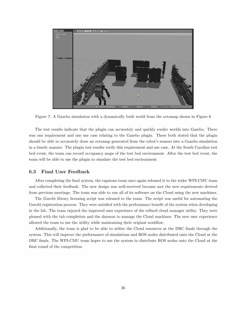
Figure 7: A Gazebo simulation with a dynamically built world from the octomap shown in Figure 6
The test results indicate that the plugin can accurately and quickly render worlds into Gazebo. There
was one requirement and one use case relating to the Gazebo plugin. These both stated that the plugin
should be able to accurately draw an octomap generated from the robot’s sensors into a Gazebo simulation
in a timely manner. The plugin test results verify this requirement and use case. At the South Carolina test
bed event, the team can record occupancy maps of the test bed environment. After the test bed event, the
team will be able to use the plugin to simulate the test bed environment.
6.3 Final User Feedback
After completing the final system, the capstone team once again released it to the wider WPI-CMU team
and collected their feedback. The new design was well-received because met the new requirements derived
from previous meetings. The team was able to run all of its software on the Cloud using the new machines.
The Gurobi library licensing script was released to the team. The script was useful for automating the
Gurobi registration process. They were satisfied with the performance benefit of the system when developing
in the lab. The team enjoyed the improved user experience of the refined cloud manager utility. They were
pleased with the tab completion and the daemon to manage the Cloud machines. The new user experience
allowed the team to use the utility while maintaining their original workflow.
Additionally, the team is glad to be able to utilize the Cloud resources at the DRC finals through the
system. This will improve the performance of simulations and ROS nodes distributed onto the Cloud at the
DRC finals. The WPI-CMU team hopes to use the system to distribute ROS nodes onto the Cloud at the
final round of the competition.
26

7 Conclusion
The goal of the capstone project was to construct a system for utilizing Cloud Computing at the DRC.
The capstone team drafted a system design after analyzing the stakeholder requirements. Then the team
implemented the system, released it to the wider WPI-CMU team, and updated it with the provided user
feedback.
The system outlined in this paper provides an easy way for the WPI-CMU team to begin leveraging the
Cloud and to develop sophisticated solutions to the problems presented at the DRC. This system is the best
way for the WPI-CMU team to prepare for the distributed processors and storage that will be available at the
DRC. The capstone team firmly believes that the system provided herein is everything that the WPI-CMU
team might need to distribute processing into the Cloud.
The system allows the WPI-CMU team members to quickly call up and utilize the power of the AWS
Cloud to speed up their workflow. This system was tested extensively. The test results indicate that the
system for running Gazebo simulations in the Cloud significantly outperforms local simulations in the lab.
The WPI-CMU team’s development cycle will benefit from the adoption of this system. This speedup will
allow the WPI-CMU team to outpace its competition both before and during the final competition.
8 Future Work
The capstone team believes that this system can be used to move complicated robotics tasks into the
Cloud. ROS is a distributed operating system. Its nodes need not be bound to one physical host. The
system that the capstone team put together is a proof of concept for more complicated systems in the future.
Cloud robotics systems like the one outlined in this paper provide a way to educate future roboticists without
the cost of providing them with their own robots to work on. A comprehensive study of what manner of
processes are best to be offloaded has yet to be performed. Such a study could identify which parts of a
given ROS system are most suitable for movement into the Cloud.
In the absence of degraded communications, tasks like those performed in the DRC could be aided by
the computational power of the Cloud. Currently expensive operations like trajectory optimization could be
offloaded to save both power and time. The Cloud used for the capstone team’s study was reliable, robust,
and low latency. Solutions like this could allow for robots like Atlas to become even more functional by
tapping into these capabilities.
Cloud robotics offers a way to allow robots to share their intelligence and to cooperate together and learn
faster than any individual system could. Multiple robots unified under a single Cloud system would be able
to instantly share information with one another: what one robot would know, every robot would know. It
would enable robots to access stored trajectories and environmental maps, making trajectory optimization
and mapping less computationally intensive. The distributed intelligence offered by Cloud robotics will
increase the pace of robotics innovation.
27

Appendices
A Testing Data
Attempt Time (seconds)1 1052 1013 1084 935 110Average 103.4
Table 14: The time it took to launch an instance on the East coast is recorded in this table.
Attempt Time (seconds)1 972 1233 1064 1145 107Average 109.4
Table 15: The time it took to launch an instance on the West coast is recorded in this table.
Map Initial Voxel Count Final Object Count Time (seconds)Two walls and a table 10019 1545 181Hallway (large) 11305 2844 341Hallway (small) 9461 1850 216Stairs 5224 951 107Trees 4906 1274 146Wall with windows(small)
3318 537 59
Wall with windows(large)
7767 1137 130
Table 16: The Plugin Results table presents the number of original voxels in each octomap, the final numberof objects that were rendered into the simulation, and the time it took to render the map in Gazebo.
References
[1] Atlas - The Agile Anthropomorphic Robot,Boston Dynamics, [online] 2013, www.bostondynamics.com/
robot_Atlas.html (Accessed: February 2015)
[2] Boston Dynamics Atlas Robot - Operation and Maintenance Manual revision 2.0,Boston Dynamics,
[online] 2015, (Accessed: February 2015)
28

[3] DARPA, Rules of the DRC Finals, (DARPA Robotics Challenge) [online] 2014, www.
theroboticschallenge.org/files/20140624DRC_Finals_Rules_Release_1_DISTAR_3.pdf (Ac-
cessed: February 2015)
[4] DARPA, Communications between Operator and Robot for the DRC Finals, (DARPA Robotics Chal-
lenge) [online] 2015, http://theroboticschallenge.org/sites/default/files/2015_01_27_Comms_
Doc_For_Teams_Release_2_DISTAR_Case_23912.pdf (Accessed: February 2015)
[5] N. Koenig and A. Howard, Design and use paradigms for Gazebo, an open-source multi-robot simulator,
in 2004, pp. 2154 vol.3.
[6] Gazebo, Gazebo, [online] 2014, http://Gazebosim.org/ (Accessed: February 2015)
[7] SDFormat, SDF, [online] 2014, http://sdformat.org/ (Accessed: February 2015)
[8] M. Quigley, K. Conley, B. Gerkey, J. Faust, T. Foote, J. Leibs, R. Wheeler and A. Y. Ng, ROS: An
open-source robot operating system, in 2009, pp. 5.
[9] Amazon Web Services, Amazon Elastic Compute Cloud, [online] 2015, http://aws.amazon.com/ec2/
(Accessed: February 2015)
[10] Felipe Polido, Worcester Polytechnic Institute Robotics Program, A Comparative Study of Robot Hands
for the DARPA Robotics Challenge [online] 2015. (Accessed: February 2015)
29
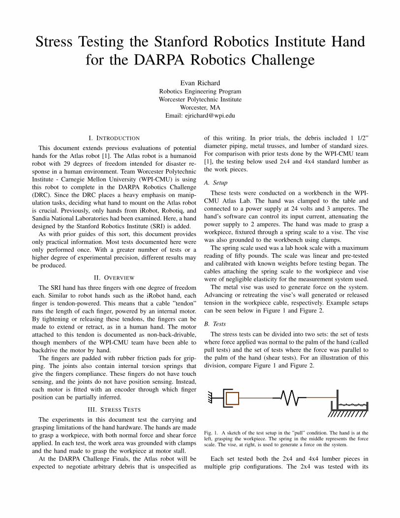
Stress Testing the Stanford Robotics Institute Handfor the DARPA Robotics Challenge
Evan RichardRobotics Engineering ProgramWorcester Polytechnic Institute
Worcester, MAEmail: [email protected]
I. INTRODUCTION
This document extends previous evaluations of potentialhands for the Atlas robot [1]. The Atlas robot is a humanoidrobot with 29 degrees of freedom intended for disaster re-sponse in a human environment. Team Worcester PolytechnicInstitute - Carnegie Mellon University (WPI-CMU) is usingthis robot to complete in the DARPA Robotics Challenge(DRC). Since the DRC places a heavy emphasis on manip-ulation tasks, deciding what hand to mount on the Atlas robotis crucial. Previously, only hands from iRobot, Robotiq, andSandia National Laboratories had been examined. Here, a handdesigned by the Stanford Robotics Institute (SRI) is added.
As with prior guides of this sort, this document providesonly practical information. Most tests documented here wereonly performed once. With a greater number of tests or ahigher degree of experimental precision, different results maybe produced.
II. OVERVIEW
The SRI hand has three fingers with one degree of freedomeach. Similar to robot hands such as the iRobot hand, eachfinger is tendon-powered. This means that a cable ”tendon”runs the length of each finger, powered by an internal motor.By tightening or releasing these tendons, the fingers can bemade to extend or retract, as in a human hand. The motorattached to this tendon is documented as non-back-drivable,though members of the WPI-CMU team have been able tobackdrive the motor by hand.
The fingers are padded with rubber friction pads for grip-ping. The joints also contain internal torsion springs thatgive the fingers compliance. These fingers do not have touchsensing, and the joints do not have position sensing. Instead,each motor is fitted with an encoder through which fingerposition can be partially inferred.
III. STRESS TESTS
The experiments in this document test the carrying andgrasping limitations of the hand hardware. The hands are madeto grasp a workpiece, with both normal force and shear forceapplied. In each test, the work area was grounded with clampsand the hand made to grasp the workpiece at motor stall.
At the DARPA Challenge Finals, the Atlas robot will beexpected to negotiate arbitrary debris that is unspecified as
of this writing. In prior trials, the debris included 1 1/2”diameter piping, metal trusses, and lumber of standard sizes.For comparison with prior tests done by the WPI-CMU team[1], the testing below used 2x4 and 4x4 standard lumber asthe work pieces.
A. Setup
These tests were conducted on a workbench in the WPI-CMU Atlas Lab. The hand was clamped to the table andconnected to a power supply at 24 volts and 3 amperes. Thehand’s software can control its input current, attenuating thepower supply to 2 amperes. The hand was made to grasp aworkpiece, fixtured through a spring scale to a vise. The visewas also grounded to the workbench using clamps.
The spring scale used was a lab hook scale with a maximumreading of fifty pounds. The scale was linear and pre-testedand calibrated with known weights before testing began. Thecables attaching the spring scale to the workpiece and visewere of negligible elasticity for the measurement system used.
The metal vise was used to generate force on the system.Advancing or retreating the vise’s wall generated or releasedtension in the workpiece cable, respectively. Example setupscan be seen below in Figure 1 and Figure 2.
B. Tests
The stress tests can be divided into two sets: the set of testswhere force applied was normal to the palm of the hand (calledpull tests) and the set of tests where the force was parallel tothe palm of the hand (shear tests). For an illustration of thisdivision, compare Figure 1 and Figure 2.
Fig. 1. A sketch of the test setup in the ”pull” condition. The hand is at theleft, grasping the workpiece. The spring in the middle represents the forcescale. The vise, at right, is used to generate a force on the system.
Each set tested both the 2x4 and 4x4 lumber pieces inmultiple grip configurations. The 2x4 was tested with its

Fig. 2. A sketch of the test setup in the ”shear” condition.
short end and its long end against the palm. The 4x4 wastested in both square and diamond configurations. That is, theworkpiece was oriented with its flat face and its edge towardsthe palm, respectively. Both the 2x4 and 4x4 were also grabbedat the very end, with the full length of the workpiece extendingout of the palm. An illustration of these configurations can beseen in Figure 3.
All grip configurations were performed twice, labelled inthe test results as ”palm” and ”fingertips”. In the palm tests,the workpiece was pressed flat against the palm before thegrab command was sent to the hand. In the fingertip tests,the workpiece was instead held approximately three inchesaway from the palm before the grab command was sent. Theworkpiece was allowed to settle from these initial conditionsinto whatever final orientation the hand gripped it in.
Failure was declared when the workpiece slipped and es-caped the hand’s grasp.
Fig. 3. The five orientations used. From left to right: 4x4 square, 4x4 diamond,2x4 short, 2x4 long, and end. The end grip was used on both the 2x4 and4x4 workpieces in the pull test only.
C. Results
The test data, collated with prior test data collected bymembers of the WPI-CMU team, appears at the end of thisdocument. For the results of the pull tests, see Table II. Theshear test results are in Table III.
The data shows that the Stanford Robotics Institute handis unequivocally stronger than any hand tested so far. Itoutperformed every hand on nearly every test, maxing outthe available spring scale in the majority of the experimentsrun. The iRobot hands beat it in two shear tests, but by lessthan a ten pound margin. Of special note is that the SRI handgenerally did better with a finger tip grip than a palm closuregrip. This is likely due to increased engagement of the frictionpads on the hand’s fingers. More of the rubber pads’ surfacearea touches the workpiece in this grip.
TABLE IAN EXAMPLE OF A TABLE
One Two
Three Four
IV. CONCLUSION
The SRI hand exhibits a much stronger grip strength thanany hand previously tested. However, for it to be used incompetition, some challenges must be overcome. In otherwords, its stronger grip strength does not necessarily meanit is the best choice. Other hands have greater degrees offreedom than the SRI hand. Further, the spring compliance ofthe SRI hand makes the fingers ”flop” about when the hand isin motion. This is difficult to reflect in the Atlas robot’s modelof itself. An accurate model of the self is necessary for taskssuch as grasping. Additionally, these stress tests caused wearon the SRI hand that began to remove the friction pads on thefingers.
It is hoped that this quantitative data can be used in a morequalitative assessment of hand selection in the future.
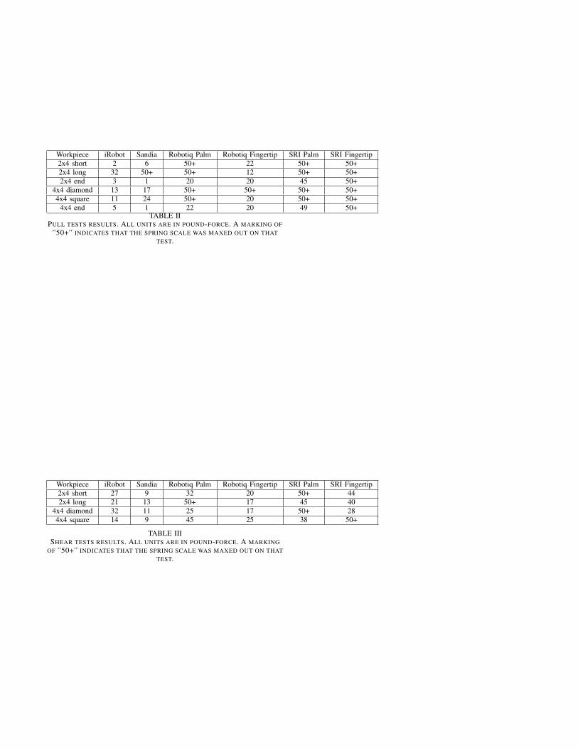
Workpiece iRobot Sandia Robotiq Palm Robotiq Fingertip SRI Palm SRI Fingertip2x4 short 2 6 50+ 22 50+ 50+2x4 long 32 50+ 50+ 12 50+ 50+2x4 end 3 1 20 20 45 50+
4x4 diamond 13 17 50+ 50+ 50+ 50+4x4 square 11 24 50+ 20 50+ 50+
4x4 end 5 1 22 20 49 50+TABLE II
PULL TESTS RESULTS. ALL UNITS ARE IN POUND-FORCE. A MARKING OF”50+” INDICATES THAT THE SPRING SCALE WAS MAXED OUT ON THAT
TEST.
Workpiece iRobot Sandia Robotiq Palm Robotiq Fingertip SRI Palm SRI Fingertip2x4 short 27 9 32 20 50+ 442x4 long 21 13 50+ 17 45 40
4x4 diamond 32 11 25 17 50+ 284x4 square 14 9 45 25 38 50+
TABLE IIISHEAR TESTS RESULTS. ALL UNITS ARE IN POUND-FORCE. A MARKING
OF ”50+” INDICATES THAT THE SPRING SCALE WAS MAXED OUT ON THATTEST.

ACKNOWLEDGMENT
This research is sponsored by Defense Advanced ResearchProject Agency, DARPA Robotics Challenge Program underContract No. HR0011-14-C-0011.
REFERENCES
[1] Felipe Polido, Worcester Polytechnic Institute Robotics Program, AComparative Study of Robot Hands for the DARPA Robotics Challenge[online] 2015. (Accessed: February 2015)