Embed Size (px)
DESCRIPTION
exhauster
Citation preview

MULTISTAGECENTRIFUGALBLOWERSZM 31
Curves are based on atmospheric conditions of 1 Atm, 68F/20C, 36% RH, and 3550 rpm
General Performance Speci�cations Standard
Technical DataNumber of Stages ............... 1 to 11
Inlet Connection .................. 3” �ange, ASA 125# / ANSI 150# drilling
Optional DIN 80 adapter �ange
Outlet Connection ................ 3” �ange, ASA 125# / ANSI 150# drilling
Optional DIN 80 adapter �ange
Operating Speed .................. Fixed speed 3550 RPM (60 Hz), 2960 RPM (50 Hz)
Variable speed option available
Casing Pressure..................... 15 PSIG (1 bar)
Seals (air) ............................ Labyrinth type
Seals (gas) .......................... OPTi Seal/ Stu�ng box type/ Carbon ring type/
Custom available
Bearings .............................. Ball, 10-year minimum life per AFBMA L10 standard
Lubrication .......................... Standard Grease
Impeller Diameter ................ 14.50 in (368.3 mm)
Impeller Tip Speed .............. 225 ft/s (68.5 m/s) direct, 321 ft/s (97.9 m/s) belt
First Critical Speed .............. 6320 RPM (11-stage)
Drive Type ........................... Direct coupled or Belt driven,
Inlet driven (standard) or Outlet driven
Shaft End ............................ 1.125 in (28.58 mm) diameter at coupling
Vibration Tolerance ............. .25 in/s (6.4 mm/s) ISO overall speci�cation,
1.25 mils (0.03 mm) peak to peak
Rotor Balance ...................... Military standard 167-1. Individual impellers and rotating assembly dynamically balanced
Materials of ConstructionCasing ................................. Cast iron ASTM A48 grade 25/30
Bearing Caps & Housings ... Cast iron ASTM A48 grade 25/30
Shaft ................................... Carbon steel AISI 4140 (stainless steel available)
Impellers ............................. Cast aluminum ANSI AA319/356 (stainless steel/custom alloys available)
Seals (air) ............................ Cast iron ASTM A48 grade 30 with lead babbitt insert Zinc-Alloy, ZA-12
Seals (gas) .......................... Consult Factory
Tie Rods .............................. .50 in (12.7 mm) diameter, high strength steel ASTM A193-B7/B7M available
Blower Base ........................ Welded structural steel ASTM A36 ASME/AWS D1.1
Motor Pedestal .................... Welded steel plate ASTM A36
Joint Sealing Compound .... RTV silicone
Base Isolation Pads ............. Neoprene rubber
Finish .................................. Standard 2 part epoxy, 7011 Atlas Copco Dark Gray
1
mbar PSIG
0
2
40
120
160
200
INLET FLOW RATE
0
2
4
5
7
8
9
SHA
FT IN
PUT
POW
ER
DIS
CHA
RGE
PRES
SURE
BHP kW
4
3
1
6
2
5
ZM 31 Blower
0
1
2
3
4
0
2
mbar inHg
27
213
240
INLET FLOW RATE
SHA
FT IN
PUT
POW
ER
INLE
T VA
CUU
M
BHP kW
1
4
6
ZM 31 Exhauster
5
187
160
133
6
3
2
3
0
100
50 100 300
m3/hr
CFM
150 250 350 400 450 500
150 200 250
1
7
3
1
10
3
4
30020050
0
100
50 100 300
m3/hr
CFM
150 250 350 400 450 500
150 200 250
30020050
4
8
7
6
5
5
7
6
53
107
80
280
240
80
www.atlascopco.uswww.e�ciencyblowers.com
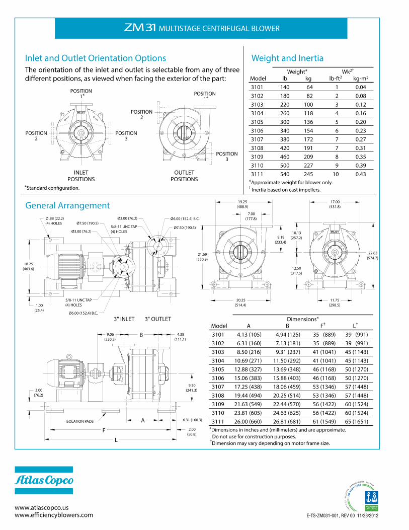
ZM 31 MULTISTAGE CENTRIFUGAL BLOWER
Inlet and Outlet Orientation OptionsThe orientation of the inlet and outlet is selectable from any of three di�erent positions, as viewed when facing the exterior of the part:
General Arrangement
Weight and Inertia
*Standard con�guration.
Dimensions* Model A B F† L†
3101 4.13 (105) 4.94 (125) 35 (889) 39 (991) 3102 6.31 (160) 7.13 (181) 35 (889) 39 (991) 3103 8.50 (216) 9.31 (237) 41 (1041) 45 (1143) 3104 10.69 (271) 11.50 (292) 41 (1041) 45 (1143) 3105 12.88 (327) 13.69 (348) 46 (1168) 50 (1270) 3106 15.06 (383) 15.88 (403) 46 (1168) 50 (1270) 3107 17.25 (438) 18.06 (459) 53 (1346) 57 (1448) 3108 19.44 (494) 20.25 (514) 53 (1346) 57 (1448) 3109 21.63 (549) 22.44 (570) 56 (1422) 60 (1524) 3110 23.81 (605) 24.63 (625) 56 (1422) 60 (1524) 3111 26.00 (660) 26.81 (681) 61 (1549) 65 (1651)
*Dimensions in inches and (millimeters) and are approximate. Do not use for construction purposes.
†Dimension may vary depending on motor frame size.
Weight* Wk2†
Model lb kg lb-ft2 kg-m2
3101 140 64 1 0.04 3102 180 82 2 0.08 3103 220 100 3 0.12 3104 260 118 4 0.16 3105 300 136 5 0.20 3106 340 154 6 0.23 3107 380 172 7 0.27 3108 420 191 7 0.31 3109 460 209 8 0.35 3110 500 227 9 0.39 3111 540 245 10 0.43*Approximate weight for blower only.† Inertia based on cast impellers.
E-TS-ZM031-001, REV 00 11/28/2012
8
POSITION 1*
POSITION2
POSITION 1*
POSITION3
OUTLETPOSITIONS
INLETPOSITIONS
POSITION2
POSITION3
3" OUTLET3" INLET
F
L
3.00(76.2)
9.50(241.3)
A2.00
(50.8)
6.31 (160.3)
4.38 (111.1)
B9.06(230.2)
ISOLATION PADS
Ø7.50 (190.5)Ø6.00 (152.4) B.C.
Ø7.50 (190.5)
18.25(463.6)
Ø3.00 (76.2)
5/8-11 UNC TAP(4) HOLES
Ø6.00 (152.4) B.C.
1.00(25.4)
Ø .88 (22.2)(4) HOLES
Ø3.00 (76.2)
5/8-11 UNC TAP(4) HOLES
22.63(574.7)
11.75(298.5)
17.00(431.8)
20.25(514.4)
10.13(257.2)9.19
(233.4)
19.25(488.9)
21.69(550.9)
12.50(317.5)
7.00(177.8)


![Atlas Copco (India) Limited · 3. Atlas Copco International B.V. ACO0101339 4. Atlas Copco AB ACO0101595, ACO0101097, A 0005191 and 10177354 5. Atlas Copco [I] Ltd Charitable Foundation](https://img.pdfslide.us/doc/110x75/5ec4197bfe534e04f779e397/atlas-copco-india-limited-3-atlas-copco-international-bv-aco0101339-4-atlas.jpg)