Embed Size (px)
Citation preview

| 0
Michael DewUnited Launch Alliance
Denver, CO
Atlas Centaur Sun Shield Design and Testing: An Update
AIAA Space 2009 ConferencePasadena, CASept 15, 2009
ILC Dover, Frederica, DE (Design, Analysis, Testing)Cliff Willey – Product MgrJohn Lin – Project Lead
John Mollura – Systems EngineerAlbert Madlangbayan – Design EngineerShobana Sivaguru – Design Engineer
Jody Ware – Materials Engineer
ULA, Denver, CO (Design, Analysis, Testing)Bernard Kutter – Mgr, Advanced Programs
Mike Dew – Lead EngineerBen Colvin – Design EngineerKirk Allwein – Thermal Analyst
Mike Logan – Systems Engineer
NASA KSC LSP (Analysis, Support)Gary O’NeilLaurie Walls
Brian Pitchford, SAS
NASA GRC (Testing, Analysis, Support)Dave Plachta – Lead Engineer
Mike McVetta – Mechanical Test EngDamir Ljubanovic – Electrical Test Eng
John Siamidis – Thermal Analyst
Innovative Engineering Solutions, Murrieta, CA (Material Testing)Parker Jasper – Staff Engineer/Lead Test Eng
David Kerner – Mgr, QA
Development Team

| 1
Centaur Sun Shield for an Atlas 400 E
nabl
es G
SO
Mis
sion
s fo
r 400
Veh
icle
Provides for longer coast missions on the 400Thermal shields, used in the past on the Atlas 500 vehicle, are protected from atmospheric air loads during launch by virtue of the fact that the Centaur is enclosed within the payload fairing On the Atlas 400 vehicle, the Centaur is exposed to the atmosphere during launch, and therefore has not flown with thermal blankets shielding the CentaurThe sun shield design is also scalable for use on a Delta upper stageThe deployable sun shield technology can be applied to:– Telescope Shades– Re-entry Shields– Solar Sails– Propellant Depots
Centaur Upper Stage

| 2
What’s a Centaur Sun Shield?
A light weight, segmented thermal radiation shield that launches in a stowed configurationDeploys after payload fairing jettison by the inflation of boomsSurrounds the Centaur’s cryogen tanks to reduce radiation heat transferA boom located at the center of each of the six trapezoids inflates independently of the other fiveWindow openings at the forward end to allow the Avionics components to meet their thermal environment requirementsAn assembly called a columnator provides for boom stowage in a small package, and provides controlled inflation pressure and speed during deployment
Vertical Boom
Horizontal Boom
Sun Shield
T-Boom Interface
Columnator
Roller Assembly

| 3
Concept of Operations

| 4
CSS First Deployment Test
Sun Shield Demo Deployment in Dec 2007
A Phase I effort took place during 2007 in a partnership between ULA and ILC Dover which resulted in a deployable proof-of-concept Sun Shield being demonstrated at a test facility in DenverCentaur Sun Shield Phase I Accomplishments – April thru Dec, 2007– Completed design of demo unit, developed manufacturing processes, built one– Successful multiple tests conducted of both individual petals and a full-up CSS
Assembly– Recording and documentation of the tests in the form of boom pressure readings,
digital photos and digital movies, with 8 different camera anglesA Phase II effort took place in 2008 thru March 2009 with a partnership between ULA, ILC, NASA Glenn Research Center (GRC) and NASA Kennedy Space Center (KSC) to define requirements, determine materials and fabrication techniques, and to test components in a vacuum chamber at cold temperatures

| 5
Centaur Sun Shield - Components
Columnator is located inside the forward end of the vertical boom. It acts as an inflation port and packing volume for the boom, and has the appropriate packing volume for boom lengthThe middle gland is adjustable externally from the boom, and is used during the packing and deployment stages– Compressed for the deployment stage, allowing it to regulate the speed and
the pressure of the boom deployment– It is decompressed and retracted for the packing stage
The top disc of the columnator helps stabilize and straighten the vertical boom during deployment. During the deployment stage, the inflation gas pushes the aft end of the vertical boom extruding the boom out and over the columnator
Vertical Boom Packed
Adjustable Middle Gland

| 6
Centaur Sun Shield - Components
The T-boom is the interface between the horizontal and vertical boomsHorizontal boom inflates after the vertical boom fully inflates
Shield
HorizBoom
Vertical Boom
Vertical-to-Horizontal Boom Interface
Photo from within Vacuum Chamber
| 7
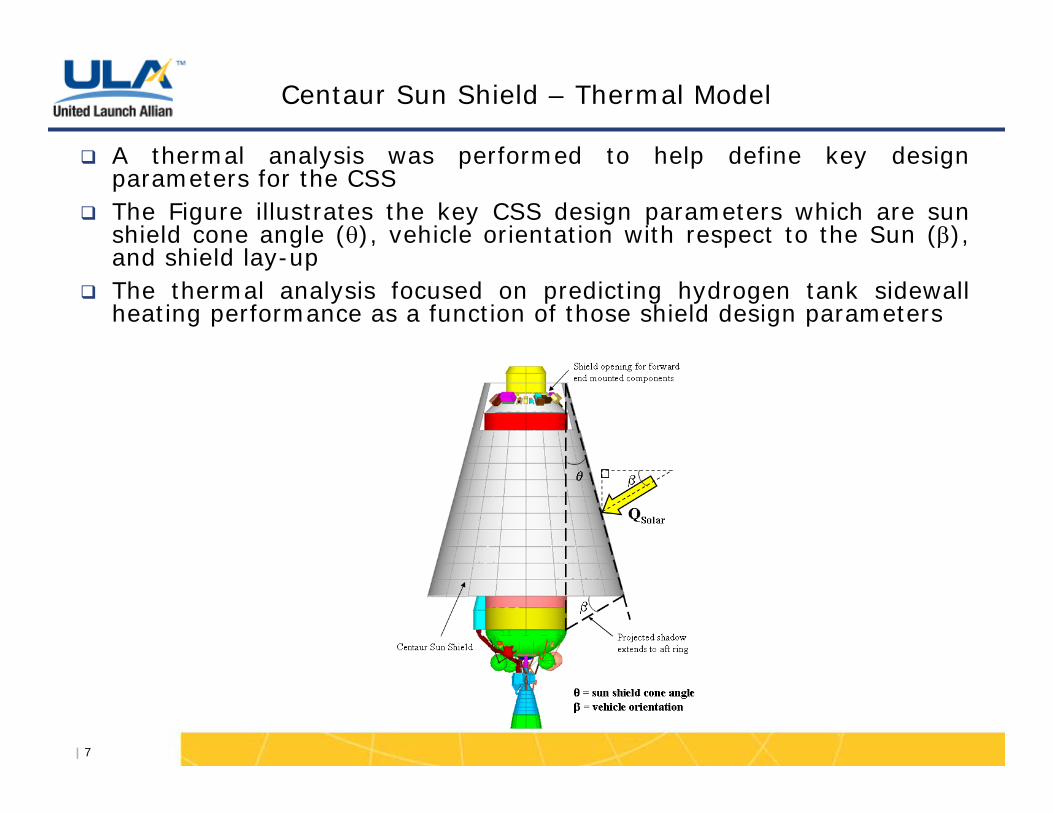
Centaur Sun Shield – Thermal Model
A thermal analysis was performed to help define key design parameters for the CSSThe Figure illustrates the key CSS design parameters which are sun shield cone angle ( ), vehicle orientation with respect to the Sun ( ), and shield lay-upThe thermal analysis focused on predicting hydrogen tank sidewall heating performance as a function of those shield design parameters

| 8
Thermal Analysis Assumptions
The CSS is deployed on-orbit after the effects of ascent aeroheatingare washed away– Fixed foam on Centaur tank
The initial CSS will be designed to reduce on-orbit hydrogen tank sidewall heating rates to the levels experienced by the Titan Centaur launch vehicleThe analysis considered varying sun shield cone anglesThe vehicle orientation was limited so the Centaur forward end and aft end mounted components will still meet their thermal requirementsThe analysis also considered number of shield layers ranging from 1 to 5, and two different shield material lay-upsWhile the sun shield is deployed it was assumed that the Centaurvehicle will be rolling about the flight axis such that it is evenly heatedIn modeling the heat transfer thru the sun shield, a radiation shield degradation factor was applied to account for on-orbit optical property degradation and contact between individual shield layersThe liquid hydrogen was modeled as a boundary condition and was constrained to a temperature of -420°F

| 9
Thermal Analysis
The tables below list two of the shield configuration cases analyzed, with optical properties for each shieldThe Figures on the next slide show the predicted sidewall tank heating performance as a function of the various shield design parametersWith the glass cloth-VDG as the outer layer, the heating rate goal can be met with a 3 to 5-layer blanketBy changing the outermost shield layer to silver coated Teflon, with its lower solar absorptivity, a substantial decrease in tank heating is realizable with the same number of layers
DAKDAKInnermost Layer
DAKDAKMiddle Layer(s)
Silver coated TeflonGlass Cloth-VDGOutermost layer
Case 2Case 1
Shield Material
Shield Layer
0.140.050.140.05DAK
0.100.850.100.85Silver Coated Teflon
0.210.030.350.81Glass Cloth-VDG
absorptivityemissivityabsorptivityemissivity
InboardOutboard
Optical Properties
Shield Materials

| 10
Thermal Analysis
Number of shield layers to accommodate heat rate design goal fordifferent half-cone angles

| 11
Testing
Thermal vacuum chamber (TVAC) tests were conducted at NASA Glenn Research Center, Cleveland in Dec 2008 thru Feb 2009– A single petal subscale engineering unit was tested – The first series of tests was deployment of the single petal at
its expected cold temperature• Observation and measurement of the CSS mechanical and
pneumatic components’ operation within a vacuum
– The second test measured the thermal performance of the sun shield in vacuum• Measurement of shield layer temperatures; cold plate heat flux,
etc.
Separate from the TVAC tests (at a different location and time), a number of material coupon tests were also performed at low temperature

| 12
Test Article After Deployment in TVAC Chamber at GRC, Dec 08 –Feb 09
TVAC Chamber at NASA Glenn, Dec 2008Ø22’ x 54’ Long
CSS single petal tests in TVAC chamber– Deployment Test: Tested the Sun Shield
materials and mechanisms in a vacuum at cold temperature
– Thermal Test – See next slide
Testing

| 13
Test Set Up ModelTVAC Chamber with single petal Test Article
Thermal Tests at NASA Glenn
Copper Plate
Single CSS Petal (3 layers)
Heater Array
Horizontal Boom
Vertical Boom

| 14
Sun Shield Development Tasks
Project Tasks Going ForwardMaterials evaluation and testing at low tempComplete component designs for the Engineering Development Unit (EDU), leading to the flight testAnalyze data from GRC tests and correlate data to analytical modelFurther define the requirements to be used in the design, development and testing of the Sun Shield–Conduct a Systems Requirements Review in Sept 2009
Continue with the design of the support structure for the Sun Shield attachment to the Atlas Launch VehicleDefine flight test measurements and instrumentation–Conduct a Preliminary Design Review in late 2009
Build an EDU and perform more development tests –2010/2011Flight Test - 2012

| 15
Summary
Design and testing to date has led to a successful demonstration of the sun shield in both ambient atmosphere, and in vacuum at low temperatureThe maturity of the sun shield design and development is leading to an SRR and PDR this yearThe ULA-ILC-NASA team made significant advancements in Sun Shield development with a relatively small budgetThe next steps are:– Complete the design– Conduct more material tests– Release drawings– Build an Engineering Development Unit (EDU)– Perform ground tests with the EDU– Use the EDU as the first flight test article
With continued funding, the team is on-track for a test flight in 2012