Embed Size (px)
Citation preview
1
ATLAS Calorimeter Argon Gap Convection Test Bed
Brian Cuerden24 Apr 2014
2
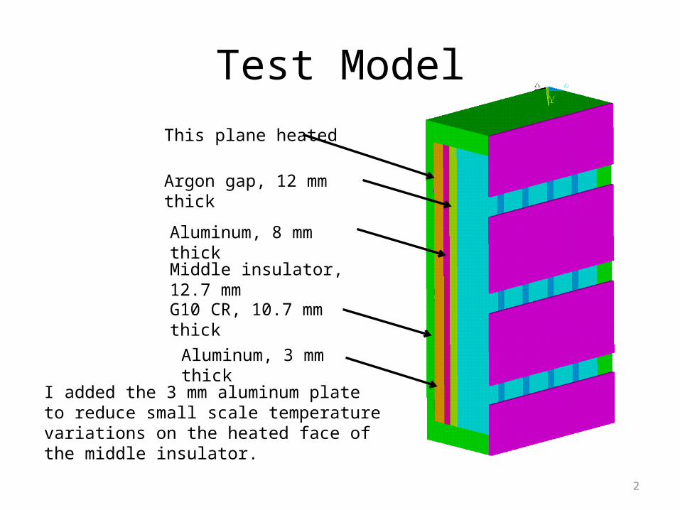
Test Model
Argon gap, 12 mm thick
Aluminum, 8 mm thick
Middle insulator, 12.7 mm
G10 CR, 10.7 mm thick
Aluminum, 3 mm thick
I added the 3 mm aluminum plate to reduce small scale temperature variations on the heated face of the middle insulator.
This plane heated
3
Earlier Results for Argon Layer Conductance
• The equation used in the previous analyses gives a conductance of 52.8 W/m2-°K for a 2 °K temperature differential (see slide 4).
• At lower temperature differentials, heat was transported from the lower regions of the inner cylinder to the upper regions of the outer cylinder, ref. slide 5, suggesting that size is more important at low temperature differentials (the convective cells that form are larger).
• A test data point at a 2 °K differential temperature is recommended. The predicted effective conductivity of the Argon layer is 4.8 times the static conductance value. For this case heat was predicted to move radially from the inner cylinder to the outer cylinder except at the top and bottom, ref. slide 6.
4
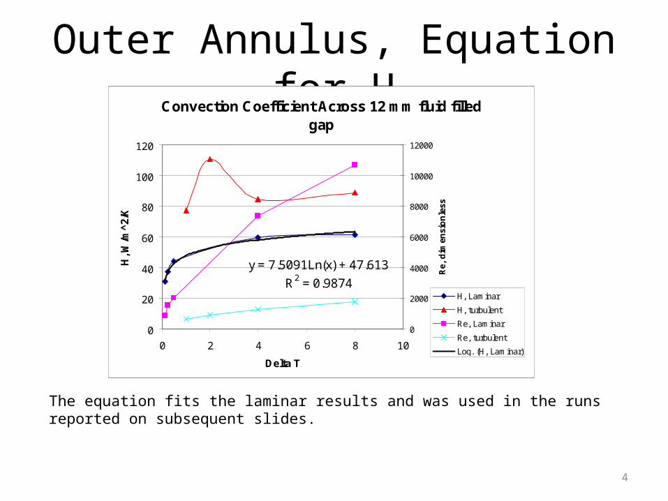
Outer Annulus, Equation for HConvection Coefficient Across 12 mm fluid filled
gap
y = 7.5091Ln(x) + 47.613
R2 = 0.9874
0
20
40
60
80
100
120
0 2 4 6 8 10
Delta T
H, W
/m^
2/K
0
2000
4000
6000
8000
10000
12000
Re,
dim
ensi
on
less
H, Laminar
H, turbulent
Re, Laminar
Re, turbulent
Log. (H, Laminar)
The equation fits the laminar results and was used in the runs reported on subsequent slides.
5
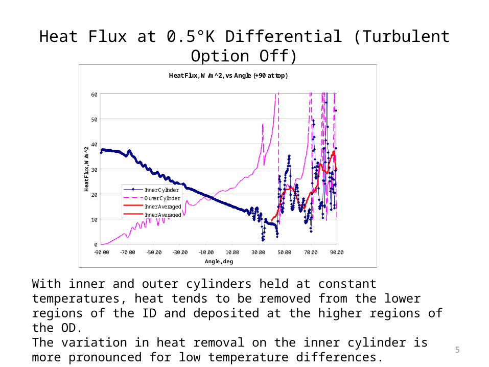
Heat Flux at 0.5°K Differential (Turbulent Option Off)
Heat Flux, W/m^2, vs Angle (+90 at top)
0
10
20
30
40
50
60
-90.00 -70.00 -50.00 -30.00 -10.00 10.00 30.00 50.00 70.00 90.00
Angle, deg
He
at
Flu
x,
W/m
^2
Inner Cylinder
Outer Cylinder
Inner Averaged
Inner Averaged
With inner and outer cylinders held at constant temperatures, heat tends to be removed from the lower regions of the ID and deposited at the higher regions of the OD. The variation in heat removal on the inner cylinder is more pronounced for low temperature differences.
6
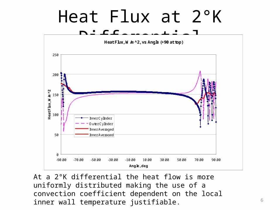
Heat Flux at 2°K DifferentialHeat Flux, W/m^2, vs Angle (+90 at top)
0
50
100
150
200
250
-90.00 -70.00 -50.00 -30.00 -10.00 10.00 30.00 50.00 70.00 90.00
Angle, deg
He
at
Flu
x,
W/m
^2
Inner Cylinder
Outer Cylinder
Inner Averaged
Inner Averaged
At a 2°K differential the heat flow is more uniformly distributed making the use of a convection coefficient dependent on the local inner wall temperature justifiable.
7
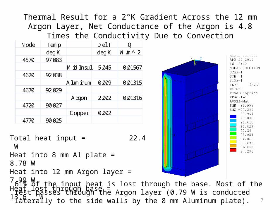
Thermal Result for a 2°K Gradient Across the 12 mm Argon Layer, Net Conductance of the Argon is 4.8 Times the Conductivity Due to Convection
Node Temp Del T Qdeg K deg K W/m̂ 2
4570 97.083Mid Insul 5.045 0.01567
4620 92.038Aluminum 0.009 0.01315
4670 92.029Argon 2.002 0.01316
4720 90.027Copper 0.002
4770 90.025
Total heat input = 22.4 WHeat into 8 mm Al plate = 8.78 WHeat into 12 mm Argon layer = 7.99 WHeat lost through base = 13.6 W
61% of the input heat is lost through the base. Most of the rest passes through the Argon layer (0.79 W is conducted laterally to the side walls by the 8 mm Aluminum plate).
8
Suggested Test Design Modification
• Small spatial scale temperature variations on the heater side of the middle insulator are possible and might effect the accuracy of the heat flux calculated from the differential temperature across this member.
• This can be reduced by adding a 3 mm plate on the heater side (assumed to be opposite from the Argon gap). Heaters should be bonded to the aluminum plate.
9
Initial Runs
• In these runs the thermal conductivity of G10 was input as an isotropic material with K=0.0014– This has been updated to K=0.000311 in-plane and
K = 0.000453 W/(m-°K) in the thickness direction• The effective conductivity of the Argon gap
was set at ten times the static conductivity of Argon.
10
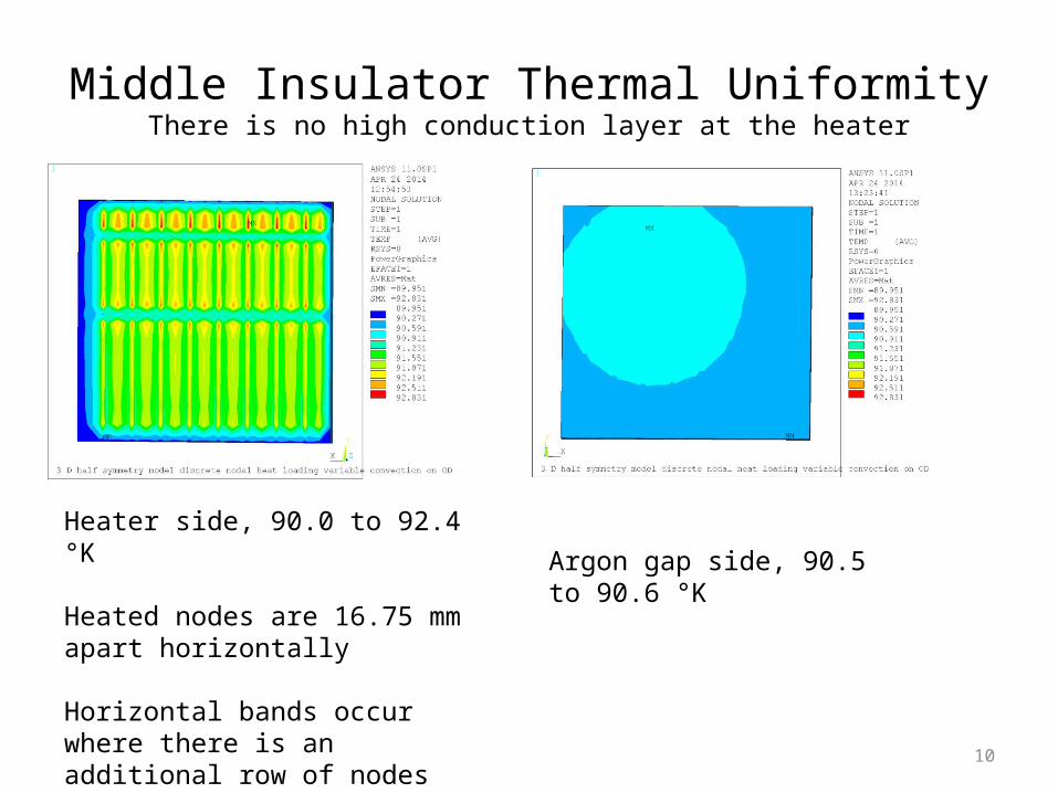
Middle Insulator Thermal UniformityThere is no high conduction layer at the heater
Heater side, 90.0 to 92.4 °K
Heated nodes are 16.75 mm apart horizontally
Horizontal bands occur where there is an additional row of nodes between heated rows
Argon gap side, 90.5 to 90.6 °K
11
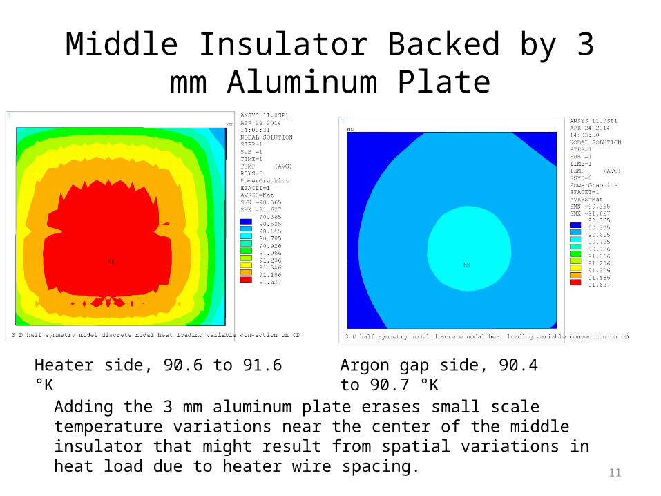
Middle Insulator Backed by 3 mm Aluminum Plate
Heater side, 90.6 to 91.6 °K Argon gap side, 90.4 to 90.7 °K
Adding the 3 mm aluminum plate erases small scale temperature variations near the center of the middle insulator that might result from spatial variations in heat load due to heater wire spacing.