Embed Size (px)
Citation preview

Address all communications and shipments to:
2645 Federal Signal DriveUniversity Park, IL 60466-3195(888)751-1500
Atkinson Dynamics Intercoms
Models AD-26, AD-27, AD-56, and AD-57
Installation and Service Instructions
INSTALLATION AND SERVICE INSTRUCTIONS FOR ATKINSON DYNAMICSHEAVY-DUTY INTERCOMS
SAFETY MESSAGE TO INSTALLERS, USERS AND MAINTENANCE PERSONNEL
It is important to follow all instructions shipped with this product. This device is to be installed by atrained electrician who is thoroughly familiar with the National Electrical Code and will follow NECGuidelines as well as local codes. Marine installations shall be in accordance with Title 46, CFR,Parts 110-113.
The selection of the mounting location for the device, its controls and the routing on the wiring is tobe accomplished under the direction of the facilities engineer and the safety engineer. In addition,listed below are some other important safety instructions and precautions you should follow:
• This is not a listed safety device and is not intended to be used as such.
• Read and understand all instructions before installing or operating this equipment.
• Disconnect power before connecting or doing any maintenance on this intercom.
• All effective warning speakers produce loud sounds which may cause in certain situations,permanent hearing loss. You should take appropriate precautions such as wearing hearingprotection.
• After testing is complete, provide a copy of this instruction sheet to all operating personnel.
• Establish a procedure to routinely check the intercom installation for integrity and properoperation. Any maintenance must be performed by a trained electrician in accordance with NECguidelines and local codes.
• This device can be installed in climates with wind blown dust and rain or splashing water. Do notinstall this device in climates that exceed the unit's operating temperature range.
Failure to follow all safety precautions and instructions may result in property damage, seriousinjury, or death to you or others.
A. General Features.
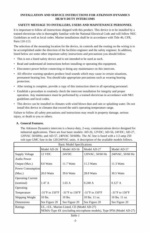
The Atkinson Dynamics intercom is a heavy-duty, 2-way, communications device designed forindustrial applications. There are four basic models: AD-26, 12VDC; AD-56, 24VDC; AD-27,120VAC 50/60Hz; and AD-57, 240VAC 50/60Hz. The AC line is fused with a 1/2-amp 250volt type GMC fuse in the 120/240VAC units. A description of the available models follows.
Basic Model Specifications
Model AD-26 Model AD-56 Model AD-27 Model AD-57
Supply Voltage 12 VDC 24VDC 120VAC, 50/60 Hz 240VAC, 50/60 Hz
Audio Power
Output (Max.) 8.0 Watts 11.7 Watts 11.3 Watts 11.3 Watts
Power Consumption
(Max.) 20.0 Watts 39.6 Watts 28.8 Watts 30.5 Watts
Operating Current
(nominal) 1.47 A 1.65 A 0.240 A 0.127 A
Operating
Temperature -31°F to 150°F -31°F to 150°F -31°F to 150°F -31°F to 150°FShipping Weight 10 lbs. 10 lbs. 10 lbs. 11 oz. 10 lbs. 11 oz
Dimensions See Figure 20 See Figure 20 See Figure 20 See Figure 20
Ratings UL, cUL, Marine-Listed, CE (Model AD-27)NEMA-Type 4X (excluding microphone models), Type IP56 (Model AD-27)
Table 1
-1-
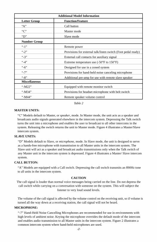
Additional Model Information
Letter Group Function/Feature
“A” Call button
“C” Master mode
“D” Slave mode
Number Group
“-1” Remote power
“-2” Provisions for external talk/listen switch (Foot pedal ready)
“-3” External call contacts for auxiliary signal
“-4” Extreme temperature use (-50°F to 150°F)
“-6” Designed for use in a zoned system
“-7” Provisions for hand-held noise canceling microphone
“-8” Additional pre-amp for use with remote slave speakerMiscellaneous
“-M22” Equipped with remote monitor switch
“-M34” Provisions for headset microphone with belt switch
“-M44” Remote speaker volume control
Table 2
MASTER UNITS:
“C” Models default to Master, or speaker, mode. In Master mode, the unit acts as a speaker andbroadcasts audio signals generated elsewhere in the intercom system. Depressing the Talk switchturns the unit into a microphone and enables the user to broadcast to all other intercoms in thesystem. Releasing the switch returns the unit to Master mode. Figure 4 illustrates a Master/Slaveintercom system.
SLAVE UNITS:
“D” Models default to Slave, or microphone, mode. In Slave mode, the unit is designed to serveas a hands-free microphone with transmission to all Master units in the intercom system. TheSlave unit will act as a speaker and broadcast audio transmissions only when the Talk switch ofany Master unit in the intercom system is depressed. Figure 4 illustrates a Master/ Slave intercomsystem.
CALL BUTTON:
“A” Models are equipped with a Call switch. Depressing the call switch transmits an 890Hz toneto all units in the intercom system.
CAUTIONThe call signal is louder than normal voice messages being carried on the line. Do not depress the
call switch while carrying on a conversation with someone on the system. This will subject thelistener to very loud sound levels.
The volume of the call signal is affected by the volume control on the receiving unit, so if volume isturned all the way down at a receiving station, the call signal will not be heard.
MICROPHONE:
“-7” Hand-Held Noise Cancelling Microphones are recommended for use in environments withhigh levels of ambient noise. Keying the microphone overrides the default mode of the intercomand enables audio transmission to all Master units in the intercom system. Figure 2 illustrates acommon intercom system where hand-held microphones are used.
-2-
-3-
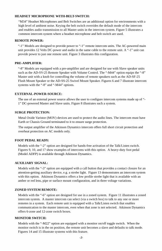
HEADSET MICROPHONE WITH-BELT-SWITCH:
“M34” Headset Microphones and Belt Switches are an additional option for environments with ahigh level of ambient noise. Keying the belt switch overrides the default mode of the intercomand enables audio transmission to all Master units in the intercom system. Figure 5 illustrates acommon intercom system where a headset microphone and belt switch are used.
REMOTE POWER:
“-1” Models are designed to provide power to “-1” remote intercom units. The AC-powered mainunit provides 12 Volts DC-power and audio in the same cable to the remote unit. A “-1” unit canprovide power to just one remote unit. Figure 3 illustrates this configuration.
PRE-AMPLIFIER:
“-8” Models are equipped with a pre-amplifier and are designed for use with Slave speaker unitssuch as the AD-SV-25 Remote Speaker with Volume Control. The “-M44” option equips the “-8”Master unit with a knob for controlling the volume of remote speakers such as the AD-SF-25Flush Mount Speaker or the AD-SS-25 Swivel Mount Speaker. Figures 6 and 7 illustrate intercomsystems with the “-8” and “-M44” options.
EXTERNAL-POWER-SOURCE:
The use of an external power source allows the user to configure intercom systems made up of “-1” DC-powered Master and Slave units. Figure 8 illustrates such a system.
SURGE PROTECTION:
Metal Oxide Varistor (MOV) devices are used to protect the audio lines. The intercom must haveEarth or Chassis Ground terminated to it to ensure surge protection.
The output amplifier of the Atkinson Dynamics intercom offers full short circuit protection andoverheat protection on AC models only.
FOOT PEDAL READY:
Models with the “-2” option are designed for hands-free activation of the Talk/Listen switch.Figures 9, 10, and 17 show examples of intercoms with this option. A heavy-duty foot pedal(Model ADFP) is available through Atkinson Dynamics.
AUXILIARY SIGNAL:
Models with the “-3” option are equipped with a call button that provides a contact closure for anattention-getting auxiliary device, e.g. a strobe light. Figure 13 demonstrates an intercom systemwith this option. Atkinson Dynamics offers a low profile strobe light that is available with anamber or red lens, pipe or surface mount configuration, and in three voltage variations.
ZONED SYSTEM REMOTE:
Models with the “-6” option are designed for use in a zoned system. Figure 11 illustrates a zonedintercom system. A master intercom can select (via a switch box) to talk to any one or moreremotes in a system. Each remote unit is equipped with a Talk/Listen switch that enablescommunication to the master intercom, even when that zone is not selected. Atkinson Dynamicsoffers 6-zone and 12-zone switch boxes.
MONITOR SWITCH:
Models with the “-M22” option are equipped with a monitor on/off toggle switch. When themonitor switch is in the on position, the remote unit becomes a slave and defaults to talk mode.Figures 14 and 15 illustrate systems with this feature.
B. Unpacking.
After unpacking the Atkinson Dynamics Intercom, examine it for damage that may haveoccurred in transit. If the equipment has been damaged, do not attempt to install or operate it,and file a claim immediately with the carrier stating the extent of the damage. Carefully checkall envelopes, shipping labels and tags before removing or destroying them.
Before attempting to install the intercom, be sure that all parts listed in the KIT CONTENTSLIST have been supplied.
C. Kit Contents List.
Qty. Description Part Number
1 Resistor, 1K, 1W 101216
D. Mounting.
CAUTIONThe selection of the mounting location for the device, its controls and the routing of the wiring
is to be accomplished under the direction of the facilities and the safety engineer.
NOTEIntercoms supplied with flexible cords for connection to field wiring are not intended
for permanent mounting.
The intercom is intended to be mounted on any relatively flat and rigid surface by the twomounting ears on the exterior of the housing. Figure 9 is a dimensional outline drawingshowing the proper mounting configuration. The two mounting ears are 13/32" diameter holesspaced 5.68" apart. Hardware for mounting the intercom to the surface shall be provided by theinstaller.
WARNINGThis unit is heavy and should be mounted on a rigid surface capable of supporting the weight
of the intercom.
WARNINGFor shipboard applications, installations shall be in accordance with the United States Coast Guard,
Title 46 CRF, Parts 110-113.
For units using the noise cancelling hand-held microphone, install the supplied microphonemounting clip on any rigid surface near the intercom. Avoid locating the microphone where itmay be exposed to excessive moisture or dust.
E. Electrical Connections.
Plug each intercom into a nearby power source with a protective earth grounding. The plugshould remain readily accessible for disconnection. Connect the audio inputs in parallel.
Audio wires should be sized properly by your licensed installation electrician for yourspecified application.
Optional: A 1K, 1W resistor is included in a kit with each intercom. Installing the resistoracross the audio lines helps to reduce noise in certain environments. Only one resistor needs tobe installed on the lines for any system installation.
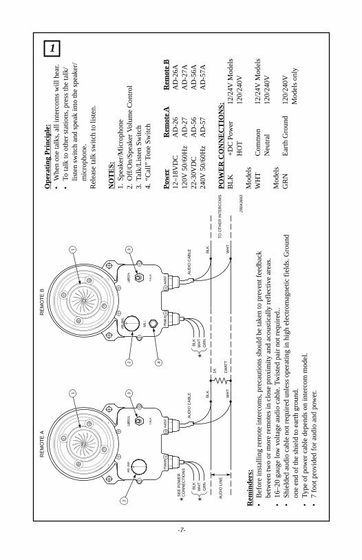
See figures 1 through 19 for typical intercom connections and wiring information.
-4-

F. Service.
1. General.
Federal Signal will service your equipment or provide technical assistance with anyproblems that cannot be handled locally.
Any units returned to Atkinson Dynamics for service, inspection, or repair must beaccompanied by a Return Material Authorization. This R.M.A can be obtained only from thefactory by calling (888)751-1500.
At this time a brief explanation of the service requested or the nature of the malfunction,should be given.
Address all communications and shipments to:
ATKINSON DYNAMICSService Department2645 Federal Signal DriveUniversity Park, IL 60466-3195
-5-
-6-
2. Replacement Parts.
WARNINGReplace fuse with GMC-1/2 only. DO NOT substitute.
Description Part NumberBelt switch assembly K137146BConnector, 3-Position (12/24V PC Boards) K140411A-03Cover plate gasket K8590013BFuse, GMC-1/2 K148A155AHeadset assembly K137145AKnob, volume control K141A129AMicrophone assembly K137144APC Board, 120VAC K2001875BPC Board, 120VAC, w/headset K2001875B-M34PC Board, 12V, AD-26 K2001878BPC Board, 12V, AD-26-7 K2001878B-06PC Board, 12V, AD-26-8 K2001896B-01PC Board, 12V, AD-26-8-M44 K2001896BPC Board, 12V, AD-26A K2001878B-05PC Board, 12V, AD-26C K2001878B-01PC Board, 12V, AD-26D K2001878B-02PC Board, 12V, AD-26SA-25 K2001878B-17PC Board, 240VAC K2001875B-01PC Board, 240VAC, w/headset K2001875B-01M34PC Board, 24V, AD-26SA-25 K2001878B-19PC Board, 24V, AD-56 K2001878B-07PC Board, 24V, AD-56-8 K2001896B-03PC Board, 24V, AD-56-8-M44 K2001896B-02PC Board, 24V, AD-56A K2001878B-12PC Board, 24V, AD-56C K2001878B-08PC Board, 24V, AD-56D K2001878B-09PC Board, 120VAC, -1 Models K2001885APC Board, 240VAC, -1 Models K2001885A-01Kit, potentiometer w/ on/off switch K8590236AKit, push button switch (12/24V models) K8590242AKit, push button switch (120/240V models) K8590241AResistor, 1K, 1W K101216ARubber boot, push button switch K288697ARubber boot, toggle switch K288696ARubber boot, volume control K288A542AKit, toggle switch, DPDT K8590238AKit, potentiometer, 10K Ohm K8590237AKit, toggle switch, 3PDT (AD-27A-M34 & AD-27A-4-M34 only) K122342AKit, toggle switch, 3PDT K8590239BKit, pushbutton switch, 3PDT K8590288AKit, potentiometer, 1K Ohm K8590289AVoice Coil/Diaphragm Assembly-Series C K8590181A
G. Warranty.
Atkinson Dynamics guarantees their intercoms to be free of defects at the time of delivery. Ifdamage is found to be a factory defect, Atkinson Dynamics will warrant all labor charges forrepair for one full year, and all replacement parts for two full years.
-7-
290A
3693
BLK
WH
T
BLK
WH
T
AU
DIO
LIN
ETO
OT
HE
R IN
TE
RC
OM
S1K 1W
ATT
AU
DIO
CA
BLE
RE
MO
TE
AR
EM
OT
E B
AU
DIO
CA
BLE
1 32
1 32 4
BLK
WH
TG
RN
*SE
E P
OW
ER
CO
NN
EC
TIO
NS
*B
LKW
HT
GR
N*
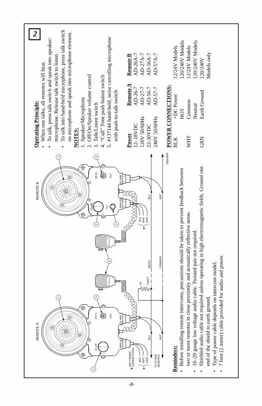
Rem
inde
rs:
•B
efor
e in
stal
ling
rem
ote
inte
rcom
s, p
reca
utio
ns s
houl
d be
take
n to
pre
vent
feed
back
betw
een
two
or m
ore
rem
otes
in c
lose
pro
xim
ity a
nd a
cous
tical
ly r
efle
ctiv
e ar
eas.
•16
–20
gaug
e lo
w v
olta
ge a
udio
cab
le. T
wis
ted
pair
not r
equi
red.
.•
Shi
elde
d au
dio
cabl
e no
t req
uire
d un
less
ope
ratin
g in
hig
h el
ectr
omag
netic
fiel
ds. G
roun
don
e en
d of
the
shie
ld to
ear
th g
roun
d.•
Type
of
pow
er c
able
dep
ends
on
inte
rcom
mod
el.
•7
foot
pro
vide
d fo
r au
dio
and
power
.
Ope
ratin
g P
rinci
ple:
•W
hen
one
talk
s, a
ll in
terc
oms
will
hea
r.
•To
talk
to o
ther
sta
tions
, pre
ss th
e ta
lk/
liste
n sw
itch
and
spea
k in
to th
e sp
eake
r/m
icro
phon
e.R
elea
se ta
lk s
witc
h to
list
en.
NO
TE
S:
1.S
peak
er/M
icro
phon
e2.
Off/
On/
Spe
aker
Vol
ume
Con
trol
3.Ta
lk/L
iste
n S
witc
h4.
“Cal
l” To
ne S
witc
h
Pow
erR
emot
e A
Rem
ote
B12
–18V
DC
AD
-26
AD
-26A
120V
50/
60H
zA
D-2
7A
D-2
7A22
-30V
DC
AD
-56
AD
-56A
240V
50/
60H
zA
D-5
7A
D-5
7A
PO
WE
R C
ON
NE
CT
ION
S:
BLK
+D
C P
ower
12/2
4V M
odel
sH
OT
120/
240V
Mod
els
WH
TC
omm
on12
/24V
Mod
els
Neu
tral
120/
240V
Mod
els
GR
NE
arth
Gro
und
120/
240V
Mod
els
only
1
BLK
WH
TG
RN
*
290A
3694
BLK
WH
T
BLK
WH
T
AU
DIO
CO
MM
ON
RE
MO
TE
AR
EM
OT
E B
TO O
TH
ER
RE
MO
TE
S
1K 1WAT
T
1 3
5
2
1 32 4
BLK
WH
TG
RN
*SE
E P
OW
ER
CO
NN
EC
TIO
NS
*
Ope
ratin
g P
rinci
ple:
•W
hen
one
talk
s, a
ll re
mot
es w
ill h
ear
.•
To ta
lk, p
ress
talk
sw
itch
and
spea
k in
to s
peak
er/
mic
roph
one.
Rel
ease
talk
sw
itch
to li
sten
.•
To ta
lk in
to h
and-
held
mic
roph
one,
pre
ss ta
lk s
witc
hon
mic
roph
one
and
spea
k in
to m
icro
phon
e el
emen
t.N
OT
ES
:1.
Spe
aker
/Mic
roph
one
2.O
ff/O
n/S
peak
er v
olum
e co
ntro
l3.
Talk
/Lis
ten
switc
h4.
“Cal
l” To
ne p
ush
butto
n sw
itch
5.#1
3714
4 ha
nd-h
eld,
noi
se c
ance
lling
mic
roph
one
with
pus
h-to
-tal
k sw
itch
Pow
erR
emot
e A
Rem
ote
B12
–18V
DC
AD
-26-
7A
D-2
6A-7
120V
50/
60H
zA
D-2
7-7
AD
-27A
-722
-30V
DC
AD
-56-
7A
D-5
6A-7
240V
50/
60H
zA
D-5
7-7
AD
-57A
-7
PO
WE
R C
ON
NE
CT
ION
S:
BLK
+D
C P
ower
12/2
4V M
odel
sH
OT
120/
240V
Mod
els
WH
TC
omm
on12
/24V
Mod
els
Neu
tral
120/
240V
Mod
els
GR
NE
arth
Gro
und
120/
240V
Mod
els
only
-8-
Rem
inde
rs:
•B
efor
e in
stal
ling
rem
ote
inte
rcom
s, p
reca
utio
ns s
houl
d be
take
n to
pre
vent
feed
back
bet
wee
ntw
o or
mor
e re
mot
es in
clo
se p
roxi
mity
and
aco
ustic
ally
ref
lect
ive
area
s.•
16–2
0 ga
uge
low
vol
tage
aud
io c
able
. Tw
iste
d pa
ir no
t req
uire
d.•
Shi
elde
d au
dio
cabl
e no
t req
uire
d un
less
ope
ratin
g in
hig
h el
ectr
omag
netic
fiel
ds. G
roun
d on
een
d of
the
shie
ld to
ear
th g
roun
d.•
Type
of
pow
er c
able
dep
ends
on
inte
rcom
mod
el.
•7
foot
(2
met
er)
cabl
e pr
ovide
d fo
r au
dio
and
power
.
2
290A
3695
GR
N
BLK
WH
T
GR
N
BLK
WH
T
1K 1WAT
T
AU
DIO
CO
MM
ON
(+)
DC
PO
WE
R
3/16
-20
AW
G
RE
MO
TE
AR
EM
OT
E B
1 32
1 32
BLK
WH
TG
RN
*SE
E P
OW
ER
CO
NN
EC
TIO
NS
*
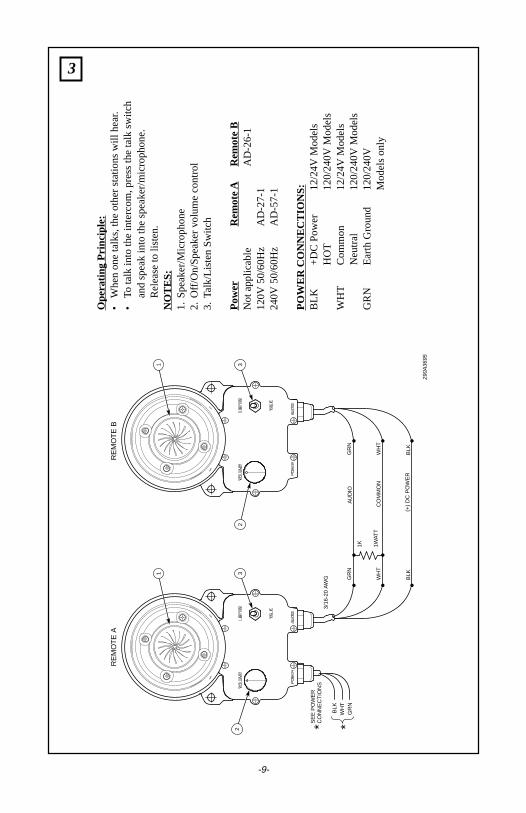
Ope
ratin
g P
rinci
ple:
•W
hen
one
talk
s, th
e ot
her
stat
ions
will
hea
r.
•To
talk
into
the
inte
rcom
, pre
ss th
e ta
lk s
witc
han
d sp
eak
into
the
spea
ker/
mic
roph
one.
Rel
ease
to li
sten
.N
OT
ES
:1.
Spe
aker
/Mic
roph
one
2.O
ff/O
n/S
peak
er v
olum
e co
ntro
l3.
Talk
/Lis
ten
Sw
itch
Pow
erR
emot
e A
Rem
ote
BN
ot a
pplic
able
AD
-26-
112
0V 5
0/60
Hz
AD
-27-
124
0V 5
0/60
Hz
AD
-57-
1
PO
WE
R C
ON
NE
CT
ION
S:
BLK
+D
C P
ower
12/2
4V M
odel
sH
OT
120/
240V
Mod
els
WH
TC
omm
on12
/24V
Mod
els
Neu
tral
120/
240V
Mod
els
GR
NE
arth
Gro
und
120/
240V
Mod
els
only
3
-9-
GR
N
BLK
WH
T
GR
N 1
BLK
3
WH
T 2
GR
N 1
BLK
3
WH
T 2
AU
DIO
CO
MM
ON
CO
NT
RO
L
290A
3696
MA
ST
ER
"A
"M
AS
TE
R "
B"
SLA
VE
1 3
4 5
2
1
1
3
2
2
1K
1W
ATT
SE
E P
OW
ER
CO
NN
EC
TIO
NS
BLK
WH
TG
RN
* *B
LKW
HT
GR
N*
BLK
WH
TG
RN
*
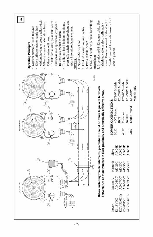
Ope
ratin
g P
rinci
ple:
•M
aste
rs n
orm
ally
list
en to
sla
ve.
•S
lave
talk
s to
mas
ter
hand
s-fr
ee,
with
out h
avin
g to
pre
ss a
talk
sw
itch.
•W
hen
any
mas
ter
talk
s, s
lave
hea
rs.
Oth
er m
aste
rs w
ill h
ear
.•
To ta
lk in
to m
aste
r, p
ress
talk
sw
itch
and
spea
k in
to s
peak
er/m
icro
phon
e.R
elea
se ta
lk s
witc
h to
list
en.
•To
talk
into
han
d-he
ld m
icro
phon
e,pr
ess
talk
sw
itch
on m
icro
phon
e an
dsp
eak
into
mic
roph
one
elem
ent.
NO
TE
S:
1.S
peak
er/M
icro
phon
e2.
Off/
On/
Spe
aker
vol
ume
cont
rol
3.P
ress
-to-
talk
Sw
itch
4.#1
3714
4 ha
nd-h
eld,
noi
se c
ance
lling
mic
roph
one
5.3-
cond
ucto
r/16
–22
gaug
e ca
ble.
Use
shie
lded
cab
le in
ele
ctric
ally
noi
syar
eas.
Gro
und
one
end
of th
e sh
ield
to“e
arth
” gr
ound
. Gro
und
chas
sis
of D
Cun
it to
gro
und.
Bef
ore
inst
allin
g re
mot
e in
terc
oms,
pre
caut
ions
sho
uld
be ta
ken to
pre
vent
feed
back
betw
een
two
or m
ore
rem
otes
in c
lose
prox
imity
and
aco
ustic
ally
refle
ctiv
e ar
eas.
Pow
erM
aste
r AM
aste
r B
Sla
ve12
–18V
DC
AD
-26C
-7A
D-2
6CA
D-2
6D12
0V 5
0/60
Hz
AD
-27C
-7A
D-2
7CA
D-2
7D22
-30V
DC
AD
-56C
-7A
D-5
6CA
D-5
6D24
0V 5
0/60
Hz
AD
-57C
-7A
D-5
7CA
D-5
7D
PO
WE
R C
ON
NE
CT
ION
S:
BLK
+D
C P
ower
12/2
4V M
odel
sH
OT
120/
240V
Mod
els
WH
TC
omm
on12
/24V
Mod
els
Neu
tral
120/
240V
Mod
els
GR
NE
arth
Gro
und
120/
240V
Mod
els
only
4
-10-
290A
3702
BLK
WH
T
BLK
WH
T
AU
DIO
CO
MM
ON
RE
MO
TE
TO O
TH
ER
INT
ER
CO
MS
1 37
56
2 4 SE
E P
OW
ER
CO
NN
EC
TIO
NS
BLK
WH
TG
RN
* *B
LKW
HT
GR
N*
1K
1W
ATT
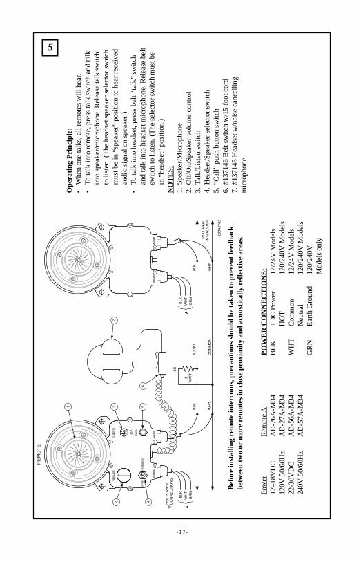
Ope
ratin
g P
rinci
ple:
•W
hen
one
talk
s, a
ll re
mot
es w
ill h
ear
.•
To ta
lk in
to r
emot
e, p
ress
talk
sw
itch
and
talk
into
spe
aker
/mic
roph
one.
Rel
ease
talk
sw
itch
to li
sten
. (T
he h
eads
et s
peak
er s
elec
tor
switc
hm
ust b
e in
“sp
eake
r” p
ositi
on to
hea
r re
ceiv
edau
dio
sign
al o
n sp
eak
er.)
•To
talk
into
hea
dset
, pre
ss b
elt “
talk
” sw
itch
and
talk
into
hea
dset
mic
roph
one.
Rel
ease
bel
tsw
itch
to li
sten
. (T
he s
elec
tor
switc
h m
ust b
ein
“he
adse
t” p
ositi
on.)
NO
TE
S:
1.S
peak
er/M
icro
phon
e2.
Off/
On/
Spe
aker
vol
ume
cont
rol
3.Ta
lk/L
iste
n sw
itch
4.H
eads
et/S
peak
er s
elec
tor
switc
h5.
“Cal
l” pu
sh b
utto
n sw
itch
6.#1
3714
6 B
elt s
witc
h w
/15
foot
cor
d7.
#137
145
Hea
dset
w/n
oise
can
celli
ngm
icro
phon
e
Bef
ore
inst
allin
g re
mot
e in
terc
oms,
pre
caut
ions
sho
uld
be ta
ken to
pre
vent
feed
back
betw
een
two
or m
ore
rem
otes
in c
lose
prox
imity
and
aco
ustic
ally
refle
ctiv
e ar
eas.
Pow
erR
emot
e A
12–1
8VD
CA
D-2
6A-M
3412
0V 5
0/60
Hz
AD
-27A
-M34
22-3
0VD
CA
D-5
6A-M
3424
0V 5
0/60
Hz
AD
-57A
-M34
PO
WE
R C
ON
NE
CT
ION
S:
BLK
+D
C P
ower
12/2
4V M
odel
sH
OT
120/
240V
Mod
els
WH
TC
omm
on12
/24V
Mod
els
Neu
tral
120/
240V
Mod
els
GR
NE
arth
Gro
und
120/
240V
Mod
els
only
5
-11-
BLK WHT
BLK 1 WHT 2
AUDIO
200 FT. MAX.
COMMON
290A3742B
MASTER
REMOTESLAVE
STATION
1
32
1
2
1K1WATT
SEE POWERCONNECTIONS
BLKWHTGRN
*
*
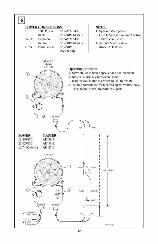
POWER CONNECTIONS:BLK +DC Power 12/24V Models
HOT 120/240V ModelsWHT Common 12/24V Models
Neutral 120/240V ModelsGRN Earth Ground 120/240V
Models only
NOTES1. Speaker/Microphone2. Off/On Speaker Volume Control3. Talk/Listen Switch4. Remote Slave Station
Model AD-SV-25
Operating Principle:1. Slave station is both a speaker and a microphone.2. Master is normally in “Listen” mode
until the talk button is pressed to talk to remote.3. Volume controls are for received signal volume only.
They do not control transmitted signals.
POWER MASTER12-18VDC AD-26-822-32VDC AD-56-8120V 50/60 Hz AD-27-8
6
-12-
BLK WHT
BLK 1 WHT 2
AUDIO
200 FT. MAX.
COMMON
290A3743B
MASTER
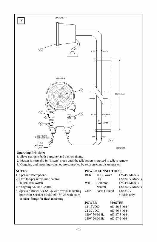
SPEAKER
1
32
5
4
SEE POWERCONNECTIONS
BLKWHTGRN
1K1WATT
*
*
NOTES:1. Speaker/Microphone2. Off/On/Speaker volume control3. Talk/Listen switch4. Outgoing Volume Control5. Speaker Model AD-SS-25 with swivel mounting
bracket or Speaker Model AD-SF-25 with holesin outer flange for flush mounting
Operating Principle:1. Slave station is both a speaker and a microphone.2. Master is normally in “Listen” mode until the talk button is pressed to talk to remote.3. Outgoing and incoming volumes are controlled by separate controls on master.
POWER CONNECTIONS:BLK +DC Power 12/24V Models
HOT 120/240V ModelsWHT Common 12/24V Models
Neutral 120/240V ModelsGRN Earth Ground 120/240V
Models only
POWER MASTER12-18VDC AD-26-8-M4422-32VDC AD-56-8-M44120V 50/60 Hz AD-27-8-M44240V 50/60 Hz AD-57-8-M44
7
-13-
GR
N
RE
D
WH
T
BLK
GR
N 1
RE
D 3
WH
T 4
BLK
2
GR
N 1
RE
D 3
WH
T 4
BLK
2
AU
DIO
+ D
C P
OW
ER
CO
MM
ON
CO
NT
RO
L
290A
3744
MA
ST
ER
"A
"M
AS
TE
R "
B"
SLA
VE
1 3
4 5
2
1
1
3
2
2
PO
WE
R
(+)
( -)
1K 1WAT
T
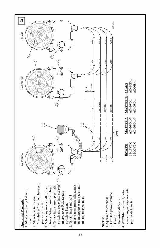
Ope
ratin
g P
rinci
ple:
1.M
aste
rs n
orm
ally
list
en to
slav
e.2.
Sla
ve ta
lks
to m
aste
rs“h
ands
-fre
e”, w
ithou
t hav
ing
topr
ess
a ta
lk s
witc
h.3.
Whe
n an
y m
aste
r ta
lks,
sla
vehe
ars.
Oth
er m
aste
r w
ill h
ear
.4.
To ta
lk in
to m
aste
r, p
ress
talk
switc
h an
d sp
eak
into
spe
aker
/m
icro
phon
e. R
elea
se ta
lksw
itch
to li
sten
.5.
To ta
lk in
to h
and-
held
mic
roph
one,
pre
ss ta
lk s
witc
hon
mic
roph
one
and
spea
k in
tom
icro
phon
e el
emen
t.
NO
TE
S:
1.S
peak
er/M
icro
phon
e2.
Off/
On/
Spe
aker
Vol
ume
Con
trol
3.P
ress
-to-
Talk
Sw
itch
4.#1
3714
4 H
and-
held
, noi
se-
canc
ellin
g m
icro
phon
e w
ithpu
sh-t
o-ta
lk s
witc
h
PO
WE
RM
AS
TE
R A
MA
ST
ER
BS
LAV
E12
-18V
DC
AD
-26C
-1-7
AD
-26C
-1A
D-2
6D-1
22-3
2VD
CA
D-5
6C-1
-7A
D-5
6C-1
AD
56D
-1
8
-14-
9
290A
4065
BLK
WH
T
BLK
GR
N
RE
D
WH
T
1K 1WA
TT
AU
DIO
CO
MM
ON
RE
MO
TE
AR
EM
OT
E B
1 32
BLK
WH
TG
RN
*SE
E P
OW
ER
CO
NN
EC
TIO
NS
TO
OT
HE
RIN
TE
RC
OM
S
*
1 3 4
2
BLK
WH
TG
RN
*
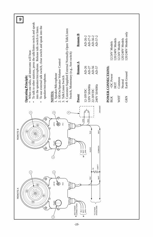
Ope
ratin
g P
rinci
ple:
•W
hen
one
talk
s, a
ll in
terc
oms
will
hea
r.
•To
talk
to o
ther
sta
tions
, pre
ss th
e ta
lk/li
sten
sw
itch
and
spea
kin
to th
e sp
eake
r/m
icro
phon
e. R
elea
se ta
lk s
witc
h to
list
en.
•To
use
ext
erna
l tal
k sw
itch,
clo
se s
witc
h an
d sp
eak
into
the
spea
ker/
mic
roph
one.
NO
TE
S:
1.S
peak
er/M
icro
phon
e2.
Off/
On/
Spe
aker
Vol
ume
Con
trol
3.Ta
lk/L
iste
n S
witc
h4.
Cus
tom
er-S
uppl
ied
Ext
erna
l Nor
mal
ly-O
pen
Tal
k/Li
sten
Sw
itch,
Mom
enta
ry (
e.g.
, foo
t sw
itch)
Pow
erR
emot
e A
Rem
ote
B
12-1
8VD
CA
D-2
6A
D-2
6-2
120V
50/
60H
zA
D-2
7A
D-2
7-2
22-3
0VD
CA
D-5
6A
D-5
6-2
240V
50/
60H
zA
D-5
7A
D-5
7-2
PO
WE
R C
ON
NE
CT
ION
S:
BLK
+D
C P
ower
12/2
4V M
odel
sH
OT
120/
240V
Mod
els
WH
TC
omm
on12
/24V
Mod
els
Neu
tral
120/
240V
Mod
els
GR
NE
arth
Gro
und
120/
240V
Mod
els
only
-15-
GR
N
WH
T
BLK
GR
N
WH
T
BLK
GR
N
WH
T
BLK
AU
DIO
CO
NT
RO
L
CO
MM
ON
290A
4066
MA
ST
ER
"A
"M
AS
TE
R "
B"
SLA
VE
3
4
2
1
3
2
2
1K
1W
AT
T
SE
E P
OW
ER
CO
NN
EC
TIO
NS
BLK
WH
TG
RN
**B
LKW
HT
GR
N*
BLK
WH
TG
RN
*
RE
D
BLU
1
PO
WE
R C
ON
NE
CT
ION
S:
BLK
+D
C P
ower
12/2
4V M
odel
sH
OT
120/
240V
Mod
els
WH
TC
omm
on12
/24V
Mod
els
Neu
tral
120/
240V
Mod
els
GR
NE
arth
Gro
und
120/
240V
Mod
els
only
Ope
ratin
g P
rinci
ple:
•M
aste
rs n
orm
ally
list
en to
sla
ve.
•S
lave
talk
s to
mas
ter
hand
s-fr
ee, w
ithou
t hav
ing
topr
ess
a ta
lk s
witc
h.•
Whe
n an
y m
aste
r ta
lks,
sla
ve h
ears
. O
ther
mas
ters
will
hea
r.•
To ta
lk in
to m
aste
r, pre
ss ta
lk s
witc
h an
d sp
eak
into
spea
ker/
mic
roph
one.
Rel
ease
talk
sw
itch
to li
sten
.•
Mas
ter
“A”
can
talk
by
pres
sing
eith
er th
e ta
lk s
witc
hor
ext
erna
l sw
itch
(cus
tom
er s
uppl
ied)
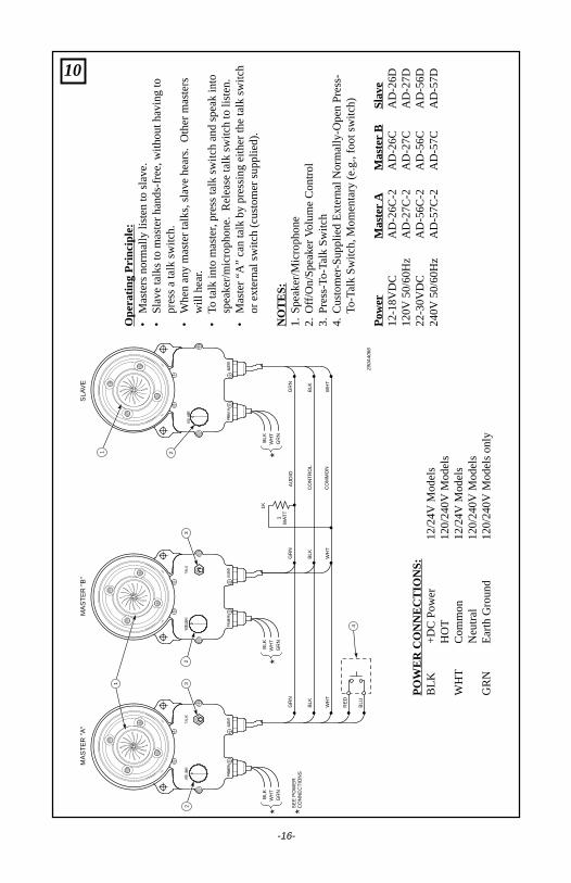
.
NO
TE
S:
1.S
peak
er/M
icro
phon
e2.
Off/
On/
Spe
aker
Vol
ume
Con
trol
3.P
ress
-To-
Talk
Sw
itch
4.C
usto
mer
-Sup
plie
d E
xter
nal N
orm
ally
-Ope
n P
ress
-To
-Tal
k S
witc
h, M
omen
tary
(e.
g., f
oot s
witc
h)
Pow
erM
aste
r A
Mas
ter
BS
lave
12-1
8VD
CA
D-2
6C-2
AD
-26C
AD
-26D
120V
50/
60H
zA
D-2
7C-2
AD
-27C
AD
-27D
22-3
0VD
CA
D-5
6C-2
AD
-56C
AD
-56D
240V
50/
60H
zA
D-5
7C-2
AD
-57C
AD
-57D10
-16-
11
-17-
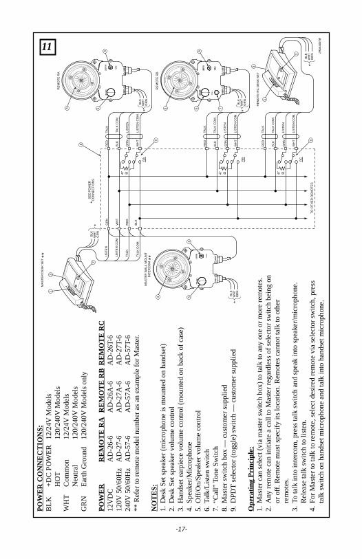
PO
WE
R C
ON
NE
CT
ION
S:
BLK
+D
C P
OW
ER
12/2
4V M
odel
sH
OT
120/
240V
Mod
els
WH
TC
omm
on12
/24V
Mod
els
Neu
tral
120/
240V
Mod
els
GR
NE
arth
Gro
und
120/
240V
Mod
els
only
PO
WE
RR
EM
OT
E R
AR
EM
OT
E R
BR
EM
OT
E R
C12
VD
CA
D-2
6-6
AD
-26A
-6A
D-2
6T-6
120V
50/
60H
zA
D-2
7-6
AD
-27A
-6A
D-2
7T-6
240V
50/
60H
zA
D-5
7-6
AD
-57A
-6A
D-5
7T-6
** R
efer
to r
emot
e m
odel
num
ber
as a
n e
xam
ple
for
Mas
ter.
NO
TE
S:
1.D
esk
Set
spe
aker
(m
icro
phon
e is
mou
nted
on
hand
set)
2.D
esk
Set
spe
aker
vol
ume
cont
rol
3.H
ands
et e
arpi
ece
volu
me
cont
rol (
mou
nted
on
back
of c
ase)
4.S
peak
er/M
icro
phon
e5.
Off/
On/
Spe
aker
vol
ume
cont
rol
6.Ta
lk/L
iste
n sw
itch
7.“C
all”
Tone
Sw
itch
8.M
aste
r sw
itch
box
— c
usto
mer
sup
plie
d9.
DP
DT
sel
ecto
r (t
oggl
e) s
witc
h —
cus
tom
er s
uppl
ied
Ope
ratin
g P
rinci
ple:
1.M
aste
r ca
n se
lect
(vi
a m
aste
r sw
itch
box)
to ta
lk to
any
one
or
mor
e re
mot
es.
2.A
ny r
emot
e ca
n in
itiat
e a
call
to M
aste
r re
gard
less
of s
elec
tor
switc
h be
ing
onor
off.
Rem
ote
mus
t spe
cify
its
loca
tion.
Rem
otes
can
not t
alk
to o
ther
rem
otes
.3.
To ta
lk in
to in
terc
om, p
ress
talk
sw
itch
and
spea
k in
to s
peak
er/m
icro
phon
e.R
elea
se ta
lk s
witc
h to
list
en.
4.F
or M
aste
r to
talk
to r
emot
e, s
elec
t des
ired
rem
ote
via
sele
ctor
sw
itch,
pre
ssta
lk s
witc
h on
han
dset
mic
roph
one
and
talk
into
han
dset
mic
roph
one.
290A
4067
B
RE
MO
TE
RB
MA
ST
ER
DE
SK
SE
T
MA
ST
ER
WA
LL M
OU
NT
INT
ER
CO
M
4 5 7
SE
E P
OW
ER
CO
NN
EC
TIO
NS
BLK
WH
TG
RN
*
*
*
****
RE
MO
TE
RA
4
8
6
3
5
BLK
WH
TG
RN
BLK
WH
TG
RN
RE
MO
TE
RC
DE
SK
SE
T
BLK
WH
TG
RN
TO
OT
HE
R R
EM
OT
ES
4
65
BLK
WH
TG
RN
*
*
*
WH
T
GR
N
RE
D
BLK
BLK
RE
D
GR
N
WH
T
TALK
CO
M.
TALK
LIS
TE
N
LIS
TE
N C
OM
.
TALK
CO
M.
TALK
LIS
TE
N
LIS
TE
N C
OM
.
TALK
CO
M.
TALK
LIS
TE
N
LIS
TE
N C
OM
.
TALK
CO
M.
TALK
LIS
TE
N
LIS
TE
N C
OM
.
BLK
RE
D
GR
N
WH
T
BLK
RE
D
RC
RB
RA
GR
N
WH
T2
3
2
99
1
1
6
12
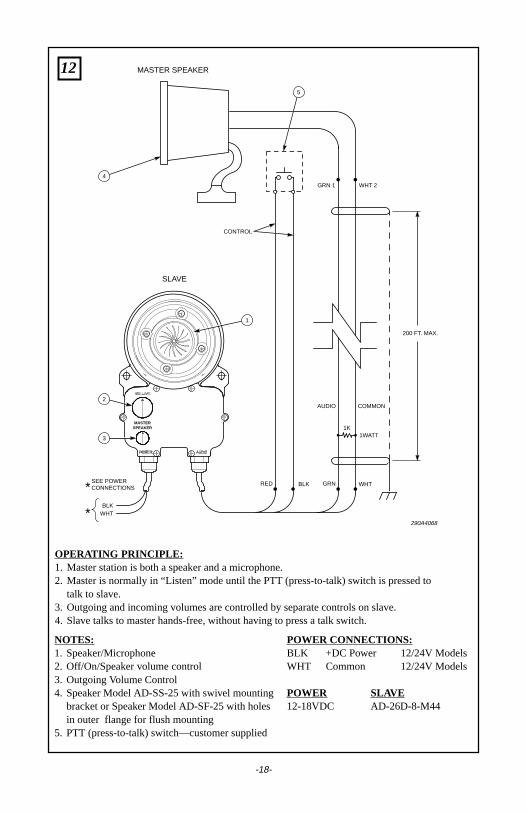
NOTES:1. Speaker/Microphone2. Off/On/Speaker volume control3. Outgoing Volume Control4. Speaker Model AD-SS-25 with swivel mounting
bracket or Speaker Model AD-SF-25 with holesin outer flange for flush mounting
5. PTT (press-to-talk) switch—customer supplied
OPERATING PRINCIPLE:1. Master station is both a speaker and a microphone.2. Master is normally in “Listen” mode until the PTT (press-to-talk) switch is pressed to
talk to slave.3. Outgoing and incoming volumes are controlled by separate controls on slave.4. Slave talks to master hands-free, without having to press a talk switch.
POWER CONNECTIONS:BLK +DC Power 12/24V ModelsWHT Common 12/24V Models
POWER SLAVE12-18VDC AD-26D-8-M44
GRN WHTRED BLK
GRN 1 WHT 2
AUDIO
CONTROL
200 FT. MAX.
COMMON
290A4068
SLAVE
MASTER SPEAKER
1
2
4
3
SEE POWERCONNECTIONS
BLKWHT
1K1WATT
*
*
5
MASTERSPEAKER
-18-
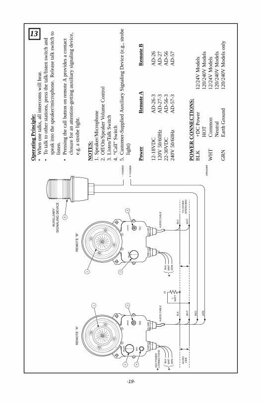
13O
pera
ting
Prin
cipl
e:•
Whe
n on
e ta
lks,
all
inte
rcom
s w
ill h
ear
.•
To ta
lk to
oth
er s
tatio
ns, p
ress
the
talk
/list
en s
witc
h an
dsp
eak
into
the
spea
ker/
mic
roph
one.
Rel
ease
talk
sw
itch
tolis
ten.
•P
ress
ing
the
call
butto
n on
rem
ote
A p
rovid
es a
con
tact
clos
ure
for
an a
ttent
ion-
getti
ng a
uxili
ary
sign
alin
g de
vice
,e.
g. a
str
obe
light
.
NO
TE
S:
1.S
peak
er/M
icro
phon
e2.
Off/
On/
Spe
aker
Vol
ume
Con
trol
3.Li
sten
/Tal
k S
witc
h4.
“Cal
l” S
witc
h5.
Cus
tom
er-S
uppl
ied
Aux
iliar
y S
igna
ling
De
vice
(e.
g., s
trob
elig
ht)
Pow
erR
emot
e A
Rem
ote
B
12-1
8VD
CA
D-2
6-3
AD
-26
120V
50/
60H
zA
D-2
7-3
AD
-27
22-3
0VD
CA
D-5
6-3
AD
-56
240V
50/
60H
zA
D-5
7-3
AD
-57
PO
WE
R C
ON
NE
CT
ION
S:
BLK
+D
C P
ower
12/2
4V M
odel
sH
OT
120/
240V
Mod
els
WH
TC
omm
on12
/24V
Mod
els
Neu
tral
120/
240V
Mod
els
GR
NE
arth
Gro
und
120/
240V
Mod
els
only
BLK
AU
DIO
CA
BLE
AU
DIO
CA
BLE
TO
OT
HE
RIN
TE
RC
OM
SA
UD
IOLI
NE
RE
D
WH
T
BLK
- P
OW
ER
+ P
OW
ER
WH
T
GR
N
290A
4069
RE
MO
TE
"A
"R
EM
OT
E "
B"
AU
XIL
LIA
RY
SIG
NA
LIN
G D
EV
ICE
1
5
3
2
1K
1W
AT
T
SE
E P
OW
ER
CO
NN
EC
TIO
NS
BLK
WH
TG
RN
* *B
LKW
HT
GR
N*
1 32 4
-19-
14
-20-
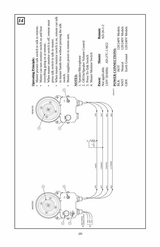
Ope
ratin
g P
rinci
ple:
•M
aste
r pr
esse
s ta
lk s
witc
h to
talk
to r
emot
e.•
Mas
ter
can
turn
mon
itor
switc
h on
and
hea
rev
eryt
hing
goi
ng o
n at
rem
ote.
•W
hen
mas
ter
mon
itor
switc
h is
of
f, re
mot
e m
ust
pres
s ta
lk s
witc
h to
talk
to m
aste
r.
•W
hen
mas
ter
mon
itor
switc
h is
on,
rem
ote
can
talk
to m
aste
r ha
nds-
free
with
out p
ress
ing
the
talk
switc
h.•
Mas
ter
supp
lies
pow
er to
rem
ote
unit.
NO
TE
S:
1.S
peak
er/M
icro
phon
e2.
Off/
On/
Spe
aker
Vol
ume
Con
trol
3.P
ress
-To-
Talk
Sw
itch
4.M
aste
r M
onito
r S
witc
h
Pow
erM
aste
rR
emot
eN
ot a
pplic
able
AD
-26-
1-2
120V
50/
60H
zA
D-2
7C-1
-M22
PO
WE
R C
ON
NE
CT
ION
S:
BLK
HO
T12
0/24
0V M
odel
sW
HT
Neu
tral
120/
240V
Mod
els
GR
NE
arth
Gro
und
120/
240V
Mod
els
GR
N
BLK
WH
T
GR
N
BLK
WH
T
AU
DIO
CO
MM
ON
CO
NT
RO
L
RE
DR
ED
(+)
PO
WE
R
290A
4070
MA
ST
ER
RE
MO
TE
1 32 4
1
3
2
1K
1W
AT
T
SE
E P
OW
ER
CO
NN
EC
TIO
NS
BLK
WH
TG
RN
* *
15
-21-
GR
N
BLK
WH
T
GR
N
BLK
WH
T
AU
DIO
CO
MM
ON
CO
NT
RO
L
290A
4071
MA
ST
ER
SLA
VE
1 32 4
1
3
2
1K
1W
AT
T
SE
E P
OW
ER
CO
NN
EC
TIO
NS
BLK
WH
TG
RN
* *B
LKW
HT
GR
N*
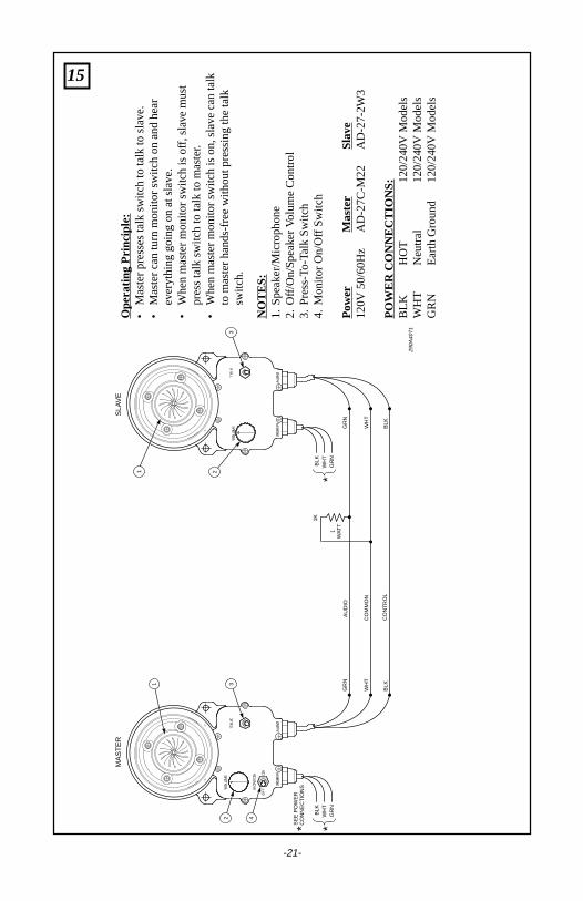
Ope
ratin
g P
rinci
ple:
•M
aste
r pr
esse
s ta
lk s
witc
h to
talk
to s
lave
.•
Mas
ter
can
turn
mon
itor
switc
h on
and
hea
rev
eryt
hing
goi
ng o
n at
sla
ve.
•W
hen
mas
ter
mon
itor
switc
h is
of
f, sl
ave
mus
tpr
ess
talk
sw
itch
to ta
lk to
mas
ter
.•
Whe
n m
aste
r m
onito
r sw
itch
is o
n, s
lave
can
talk
to m
aste
r ha
nds-
free
with
out p
ress
ing
the
talk
switc
h.
NO
TE
S:
1.S
peak
er/M
icro
phon
e2.
Off/
On/
Spe
aker
Vol
ume
Con
trol
3.P
ress
-To-
Talk
Sw
itch
4.M
onito
r O
n/O
ff S
witc
h
Pow
erM
aste
rS
lave
120V
50/
60H
zA
D-2
7C-M
22A
D-2
7-2W
3
PO
WE
R C
ON
NE
CT
ION
S:
BLK
HO
T12
0/24
0V M
odel
sW
HT
Neu
tral
120/
240V
Mod
els
GR
NE
arth
Gro
und
120/
240V
Mod
els
16
-22-
GR
N
RE
D
WH
T
BLK
GR
N
RE
D
WH
T
BLK
GR
N
RE
D
WH
T
BLK
AU
DIO
+ D
C P
OW
ER
CO
MM
ON
CO
NT
RO
L
290A
4072
MA
ST
ER
"A
"S
LAV
EM
AS
TE
R "
B"
3
3
2 4 8
4
1
77
2
211
DC
PO
WE
R
(+)
(-)
1K 1WA
TT
5
6
4
RE
DB
LKG
RN
WH
T
SP
KR
HE
AD
SE
TS
PK
RH
EA
DS
ET
SP
KR
HE
AD
SE
T
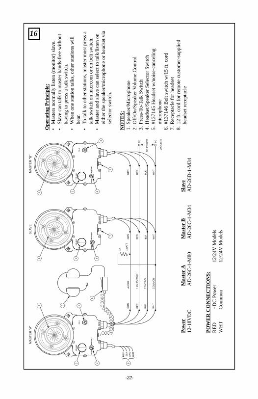
Ope
ratin
g P
rinci
ple:
•M
aste
rs n
orm
ally
list
en (
mon
itor)
slave
.•
Sla
ve c
an ta
lk to
mas
ter
hand
s-fr
ee w
ithou
tha
ving
to p
ress
a ta
lk s
witc
h.•
Whe
n on
e st
atio
n ta
lks,
oth
er s
tatio
ns w
illhe
ar.
•To
talk
to o
ther
sta
tions
, mas
ter
mus
t pre
ss a
talk
sw
itch
on in
terc
om o
r on
bel
t sw
itch.
•M
aste
r an
d sl
ave
can
sele
ct to
talk
/list
en o
nei
ther
the
spea
ker/
mic
roph
one
or h
eads
et v
iase
lect
or s
witc
h.
NO
TE
S:
1.S
peak
er/M
icro
phon
e2.
Off/
On/
Spe
aker
Vol
ume
Con
trol
3.P
ress
-To-
Talk
Sw
itch
4.H
eads
et/S
peak
er S
elec
tor
Sw
itch
5.#1
3714
5 H
eads
et w
/noi
se-c
ance
ling
mic
roph
one
6.#1
3714
6 B
elt s
witc
h w
/15
ft. c
ord
7.R
ecep
tacl
e fo
r he
adse
t8.
12 ft
. cor
d fo
r re
mot
e cu
stom
er-sup
plie
dhe
adse
t rec
epta
cle
Pow
erM
aste
r A
Mas
ter
BS
lave
12-1
8VD
CA
D-2
6C-1
-M80
AD
-26C
-1-M
34A
D-2
6D-1
-M34
PO
WE
R C
ON
NE
CT
ION
S:
RE
D+
DC
Pow
er12
/24V
Mod
els
WH
TC
omm
on12
/24V
Mod
els
17
-23-
GR
N
RE
D
WH
T
BLK
GR
N
WH
TOB
SE
RV
E C
OLO
R C
OD
E
GR
N
RE
D
WH
T
BLK
AU
DIO
+ D
C P
OW
ER
CO
MM
ON
CO
NT
RO
L
AU
DIO
+ D
C P
OW
ER
CO
MM
ON
CO
NT
RO
L
290A
4073
MA
ST
ER
"A
"M
AS
TE
R "
B"
SLA
VE
3
5
2
1
3
2
2
PO
WE
R
(+)
(-)
1K
1WA
TT
1
4
RE
D
BR
N
OR
YE
L
* BLU
(
+ D
C P
OW
ER
FR
OM
MA
ST
ER
"B
")*
BLK
(
CO
NT
RO
L F
RO
M M
AS
TE
R "
B")
*
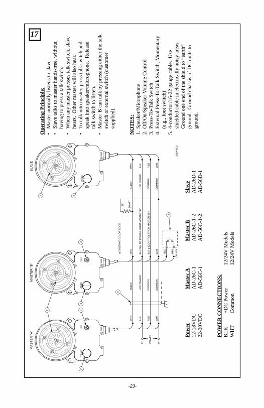
Ope
ratin
g P
rinci
ple:
•M
aste
r no
rmal
ly li
sten
s to
sla
ve.
•S
lave
talk
s to
mas
ter
hand
s-fr
ee, w
ithou
tha
ving
to p
ress
a ta
lk s
witc
h.•
Whe
n an
y m
aste
r pr
esse
s ta
lk s
witc
h, s
lave
hear
s. O
ther
mas
ter
will
als
o he
ar.
•To
talk
into
mas
ter,
pre
ss ta
lk s
witc
h an
dsp
eak
into
spe
aker
/mic
roph
one.
Rel
ease
talk
sw
itch
to li
sten
.•
Mas
ter
B c
an ta
lk b
y pr
essi
ng e
ither
the
talk
switc
h or
ext
erna
l sw
itch
(cus
tom
ersu
pplie
d).
NO
TE
S:
1.S
peak
er/M
icro
phon
e2.
Off/
On/
Spe
aker
Vol
ume
Con
trol
3.P
ress
-To-
Talk
Sw
itch
4.E
xter
nal P
ress
-To-
Talk
Sw
itch,
Mom
enta
ry(e
.g.,
foot
sw
itch)
5.4-
cond
ucto
r/16
-22
gaug
e ca
ble.
Use
shie
lded
cab
le in
ele
ctric
ally
noi
sy a
reas
.G
roun
d on
e en
d of
the
shie
ld to
“ea
rth”
grou
nd.
Gro
und
chas
sis
of D
C u
nits
togr
ound
.
Pow
erM
aste
r A
Mas
ter
BS
lave
12-1
8VD
CA
D-2
6C-1
AD
-26C
-1-2
AD
-26D
-122
-30V
DC
AD
-56C
-1A
D-5
6C-1
-2A
D-5
6D-1
PO
WE
R C
ON
NE
CT
ION
S:
BLK
+D
C P
ower
12/2
4V M
odel
sW
HT
Com
mon
12/2
4V M
odel
s
18
-24-
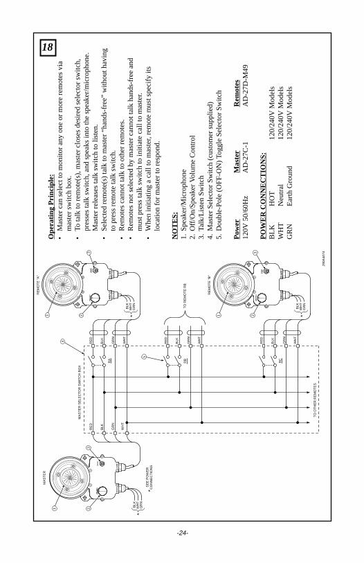
Ope
ratin
g P
rinci
ple:
•M
aste
r ca
n se
lect
to m
onito
r an
y on
e or
mor
e re
mot
es v
iam
aste
r sw
itch
box.
•To
talk
to r
emot
e(s)
, mas
ter
clos
es d
esire
d se
lect
or s
witc
h,pr
esse
s ta
lk s
witc
h, a
nd s
peak
s in
to th
e sp
eake
r/m
icro
phon
e.M
aste
r re
leas
es ta
lk s
witc
h to
list
en.
•S
elec
ted
rem
ote(
s) ta
lk to
mas
ter
“han
ds-f
ree”
with
out h
avin
gto
pre
ss r
emot
e ta
lk s
witc
h.•
Rem
otes
can
not t
alk
to o
ther
rem
otes
.•
Rem
otes
not
sel
ecte
d by
mas
ter
cann
ot ta
lk h
ands
-fre
e an
dm
ust p
ress
talk
sw
itch
to in
itiat
e ca
ll to
mas
ter
.•
Whe
n in
itiat
ing
a ca
ll to
mas
ter
, rem
ote
mus
t spe
cify
its
loca
tion
for
mas
ter
to r
espo
nd.
NO
TE
S:
1.S
peak
er/M
icro
phon
e2.
Off/
On/
Spe
aker
Vol
ume
Con
trol
3.Ta
lk/L
iste
n S
witc
h4.
Mas
ter
Sel
ecto
r S
witc
h (c
usto
mer
sup
plie
d)5.
Dou
ble-
Pol
e (O
FF
-ON
) Tog
gle
Sel
ecto
r S
witc
h
Pow
erM
aste
rR
emot
es12
0V 5
0/60
Hz
AD
-27C
-1A
D-2
7D-M
49
PO
WE
R C
ON
NE
CT
ION
S:
BLK
HO
T12
0/24
0V M
odel
sW
HT
Neu
tral
120/
240V
Mod
els
GR
NE
arth
Gro
und
120/
240V
Mod
els
290A
4074
RE
MO
TE
"B
"
MA
ST
ER
SE
E P
OW
ER
CO
NN
EC
TIO
NS
MA
ST
ER
SE
LEC
TO
R S
WIT
CH
BO
X
TO
RE
MO
TE
RB
*
RE
MO
TE
"A
"
1
4
2
BLK
WH
TG
RN
TO
OT
HE
R R
EM
OT
ES
1
32
BLK
WH
TG
RN
**
BLK
WH
TG
RN
*
BLK
RE
D
GR
N
WH
T
BLK
RE
D
GR
N
WH
T
BLK
RE
D
GR
N
WH
T
BLK
RE
D
RC
RB
RA
GR
N
WH
T
5
3
1 23
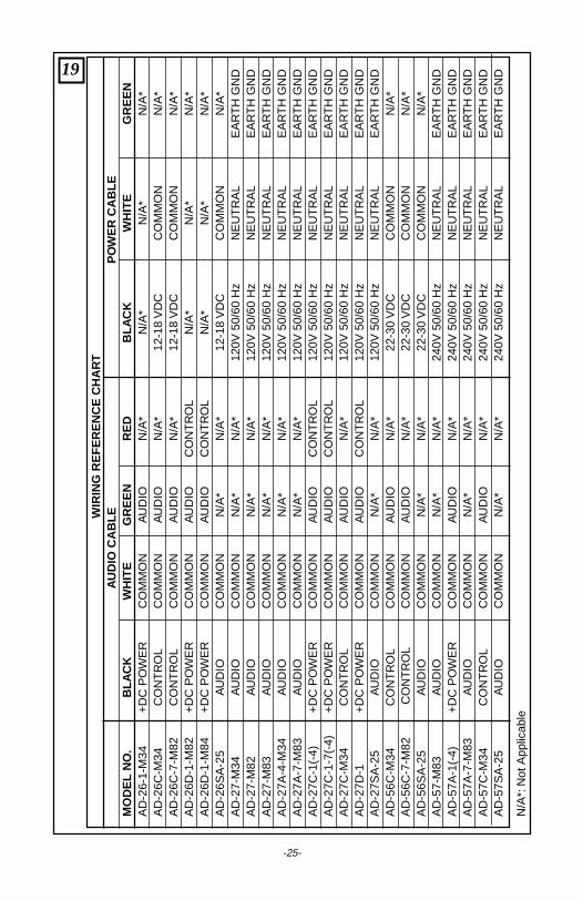
19W
IRIN
G R
EF
ER
EN
CE
CH
AR
TA
UD
IO C
AB
LEP
OW
ER
CA
BLE
MO
DE
L N
O.
BLA
CK
WH
ITE
GR
EE
NR
ED
BLA
CK
WH
ITE
GR
EE
NA
D-2
6-1-
M34
+D
C P
OW
ER
CO
MM
ON
AU
DIO
N/A
*N
/A*
N/A
*N
/A*
AD
-26C
-M34
CO
NT
RO
LC
OM
MO
NA
UD
ION
/A*
12-1
8 V
DC
CO
MM
ON
N/A
*A
D-2
6C-7
-M82
CO
NT
RO
LC
OM
MO
NA
UD
ION
/A*
12-1
8 V
DC
CO
MM
ON
N/A
*A
D-2
6D-1
-M82
+D
C P
OW
ER
CO
MM
ON
AU
DIO
CO
NT
RO
LN
/A*
N/A
*N
/A*
AD
-26D
-1-M
84+
DC
PO
WE
RC
OM
MO
NA
UD
IOC
ON
TR
OL
N/A
*N
/A*
N/A
*A
D-2
6SA
-25
AU
DIO
CO
MM
ON
N/A
*N
/A*
12-1
8 V
DC
CO
MM
ON
N/A
*A
D-2
7-M
34A
UD
IOC
OM
MO
NN
/A*
N/A
*12
0V 5
0/60
Hz
NE
UT
RA
LE
AR
TH
GN
DA
D-2
7-M
82A
UD
IOC
OM
MO
NN
/A*
N/A
*12
0V 5
0/60
Hz
NE
UT
RA
LE
AR
TH
GN
DA
D-2
7-M
83A
UD
IOC
OM
MO
NN
/A*
N/A
*12
0V 5
0/60
Hz
NE
UT
RA
LE
AR
TH
GN
DA
D-2
7A-4
-M34
AU
DIO
CO
MM
ON
N/A
*N
/A*
120V
50/
60 H
zN
EU
TR
AL
EA
RT
H G
ND
AD
-27A
-7-M
83A
UD
IOC
OM
MO
NN
/A*
N/A
*12
0V 5
0/60
Hz
NE
UT
RA
LE
AR
TH
GN
DA
D-2
7C-1
(-4)
+D
C P
OW
ER
CO
MM
ON
AU
DIO
CO
NT
RO
L12
0V 5
0/60
Hz
NE
UT
RA
LE
AR
TH
GN
DA
D-2
7C-1
-7(-
4)+
DC
PO
WE
RC
OM
MO
NA
UD
IOC
ON
TR
OL
120V
50/
60 H
zN
EU
TR
AL
EA
RT
H G
ND
AD
-27C
-M34
CO
NT
RO
LC
OM
MO
NA
UD
ION
/A*
120V
50/
60 H
zN
EU
TR
AL
EA
RT
H G
ND
AD
-27D
-1+
DC
PO
WE
RC
OM
MO
NA
UD
IOC
ON
TR
OL
120V
50/
60 H
zN
EU
TR
AL
EA
RT
H G
ND
AD
-27S
A-2
5A
UD
IOC
OM
MO
NN
/A*
N/A
*12
0V 5
0/60
Hz
NE
UT
RA
LE
AR
TH
GN
DA
D-5
6C-M
34C
ON
TR
OL
CO
MM
ON
AU
DIO
N/A
*22
-30
VD
CC
OM
MO
NN
/A*
AD
-56C
-7-M
82 C
ON
TR
OL
CO
MM
ON
AU
DIO
N/A
*22
-30
VD
CC
OM
MO
NN
/A*
AD
-56S
A-2
5A
UD
IOC
OM
MO
NN
/A*
N/A
*22
-30
VD
CC
OM
MO
NN
/A*
AD
-57-
M83
AU
DIO
CO
MM
ON
N/A
*N
/A*
240V
50/
60 H
zN
EU
TR
AL
EA
RT
H G
ND
AD
-57A
-1(-
4)+
DC
PO
WE
RC
OM
MO
NA
UD
ION
/A*
240V
50/
60 H
zN
EU
TR
AL
EA
RT
H G
ND
AD
-57A
-7-M
83A
UD
IOC
OM
MO
NN
/A*
N/A
*24
0V 5
0/60
Hz
NE
UT
RA
LE
AR
TH
GN
DA
D-5
7C-M
34C
ON
TR
OL
CO
MM
ON
AU
DIO
N/A
*24
0V 5
0/60
Hz
NE
UT
RA
LE
AR
TH
GN
DA
D-5
7SA
-25
AU
DIO
CO
MM
ON
N/A
*N
/A*
240V
50/
60 H
zN
EU
TR
AL
EA
RT
H G
ND
N/A
*: N
ot A
pplic
able
-25-
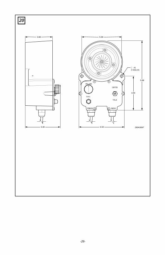
3.88 5.68
5.00 6.50
4.84
9.88
290A3697
.412 HOLES∅
20
-26-

2561494HREV. H Printed 11/06Printed in U.S.A.