Embed Size (px)
Citation preview
ATINER CONFERENCE PAPER SERIES No: LNG2014-1176
1
Athens Institute for Education and Research
ATINER
ATINER's Conference Paper Series
CIV2015-1719
Thomas L. Attard
Associate Professor
University of Alabama at Birmingham
USA
Hongyu Zhou
Assistant Professor
University of Alabama in Huntsville
USA
Damage Absorption of High-Impact
Structural Systems using Time-Reaction of
Hybridized Epoxy-Polyurea Interfaces
ATINER CONFERENCE PAPER SERIES No: CIV2015-1719
An Introduction to
ATINER's Conference Paper Series
ATINER started to publish this conference papers series in 2012. It includes only the
papers submitted for publication after they were presented at one of the conferences
organized by our Institute every year. This paper has been peer reviewed by at least two
academic members of ATINER.
Dr. Gregory T. Papanikos
President
Athens Institute for Education and Research
This paper should be cited as follows:
Attard, T. L. and Zhou, H. (2015). "Damage Absorption of High-Impact
Structural Systems using Time-Reaction of Hybridized Epoxy-Polyurea
Interfaces", Athens: ATINER'S Conference Paper Series, No: CIV2015-1719.
Athens Institute for Education and Research
8 Valaoritou Street, Kolonaki, 10671 Athens, Greece
Tel: + 30 210 3634210 Fax: + 30 210 3634209 Email: [email protected] URL:
www.atiner.gr
URL Conference Papers Series: www.atiner.gr/papers.htm
Printed in Athens, Greece by the Athens Institute for Education and Research. All rights
reserved. Reproduction is allowed for non-commercial purposes if the source is fully
acknowledged.
ISSN: 2241-2891
25/11/2015
ATINER CONFERENCE PAPER SERIES No: CIV2015-1719
Damage Absorption of High-Impact Structural Systems using
Time-Reaction of Hybridized Epoxy-Polyurea Interfaces
Thomas L. Attard
Hongyu Zhou
Abstract
A carbon-fiber reinforced hybrid-polymeric matrix (CHMC) composite was
developed for vibration suppression applications, where the hybrid matrix
system was created by combining two polymeric compounds - the epoxy-based
phase I which has highly crosslinked morphology and the lightly-crosslinked
polyurea elastomeric phase II which when reacted with curing phase I,
provides high damping and fracture toughness. The chemical reactions
incurring the hybrid matrix system are discussed. The microstructures and
micromechanical properties of CHMC are examined through scanning electron
microscopy and nanoindentation. Dynamic properties of CHMC as well as
conventional carbon-fiber reinforced epoxies are investigated using free
vibration and randomly excited vibration tests, and test results indicate CHMC
exhibits significantly greater damping than carbon-fiber/epoxy. The influence
of two material processing parameters - the polyurea thickness hp and elapsed
curing time tc of epoxy - on material damping is investigated. Generally,
damping coefficients increase with greater hp and smaller tc.
Keywords: Composite Vibrations, Electron microscopy; Hybrid, Internal
friction/damping, Polyurea
Acknowledgments: This research was partially supported by Department of
Homeland Security through the Higher Education Research Experience
(HERE) Program, and by the Southeast Region Research Initiative (SERRI) at
the Department of Energy’s Oak Ridge National Laboratory (ORNL), DHS
Project No. 90300.
ATINER CONFERENCE PAPER SERIES No: CIV2015-1719
Introduction
Damping is an important property that influences the dynamic behaviors
of various materials and structures, in particular the behaviors of those used in
vibration sensitive applications. In order to minimize resonance and suppress
resonant or near-resonant vibrations, high damping materials are often desired
in structural designs. The benefits of using higher-damped structural materials
include extending the service life of the various structural components,
reducing noise, and reducing structural weight. Most polymeric matrix
composites (PMCs) intrinsically have significantly higher damping than
metallic materials, and the damping mechanisms in composite materials differ
from those observed in conventional structural materials, such as metals and
alloys. At the constituent level, the energy dissipation in fibrous composites is
induced by 1) the viscoelastic/viscoplastic nature of the comprising fiber and
matrix constituents, 2) the interaction between material phases, and 3) any
damage that may exist in the material, either from a pre-existing condition or
newly formed state (Nashif et al., 1985). At the laminate level, the damping of
fibrous composites depends not only on the constituent lamina (or ply)
properties, but also on the ply orientations and inter-laminar effects (Berthelot
and Sefrani, 2003).
In the design of structural materials, it is often contradictory to obtain high
stiffness and high damping, i.e., bulk materials that combine high damping and
high stiffness are not common (Lakes, 2002). The microstructure of some
composite materials gives rise to combined high stiffness and high damping.
These materials are often composed of a stiff, low damping phase (e.g.
reinforcing fibers) and a compliant, high damping phase. The inclusion of soft
particulate phases, such as the core-shell rubber (SCR), into epoxy-based
matrices has been proved to be an effective method to improve damping
(Cawse and Stanford, 1987; Tsai et al., 2009); however, reduction in material
stiffness is often substantial. In this light, multilayered Carbon-fiber reinforced
Hybrid-Matrix Composite, or CHMC, is developed to provide high material
damping while maintaining ambient stiffness and low fabrication cost. Earlier
studies conducted by Zhou and Attard (2013) and Zhou et al. (2013)
demonstrated the potential of CHMC as a structural retrofitting material to
sustain strength of otherwise brittle substrates and preclude failure. In the
present study, chemical reactions involved in CHMC fabrication process are
discussed; microstructural and micromechanical properties of CHMC are
characterized using scanning electron microscopy (SEM) and nanoindentation;
and dynamic properties of CHMC and CHMC/steel composite beams are
studied through free vibration and randomly-excited forced vibration tests. Test
results are compared to those obtained from carbon-fiber reinforced epoxy
(CFE, also commonly referred to as CFRP) beams; and the mechanisms
enabling enhanced damping in the CHMC are discussed.
ATINER CONFERENCE PAPER SERIES No: CIV2015-1719
The Carbon-Fiber Reinforced Hybrid Matrix Composite (CHMC)
Multilayered Morphology, Chemical Composition, and Microstructures
While the strength and stiffness of continuous fibrous composites are
mostly governed by the fiber properties, the matrix phases in composite
materials provide stress transferring paths for the reinforcing fibers; thus, the
matrix phase, at least to some extent, affects the fracture toughness of the
composites (Agarwal et al., 2006) and the general energy dissipation
capacities. Most thermosetting polymers, such as epoxies, fracture within a
relatively low strain range; as a result, damages initiated in the reinforcing
fibers or at the fiber-matrix interface quickly bridge together via matrix
cracking causing imminent failure of the material system. One solution to
improve the damage tolerance of polymeric composites is to induce "damage
barriers" so that microscopic damage events can be isolated, rendering any
singe crack harmless (Zhou et al. 2013). To implement this concept,
elastomeric layers were introduced in the epoxy base matrix. The hybrid
polymeric matrix system combines the high stiffness and good fiber saturation
of epoxy-based polymers with the high damping and fracture toughness of
lightly-crosslinked elastomers.
The multilayered cross-ply morphology of CHMC is schematically shown
in Figure 1a and 1b, where the "self-supporting" laminates are stand-alone
composite laminates used to manufacture, for example, mechanical
components, whereas in a retrofitting application, the laminates may be
attached to a substrate, such as steel or concrete, to provide a requisite strength.
The hybrid matrix system of the CHMC is created by saturating the reinforcing
carbon fiber in an epoxy-based matrix phase I, where the condensation
crosslinking reaction between epoxy resin molecules, i.e., in this case the
Bisphenol A diglycidal ether, and the hardener (polyetheramine) takes place to
form a highly crosslinked structure, see Scheme 1.
ATINER CONFERENCE PAPER SERIES No: CIV2015-1719
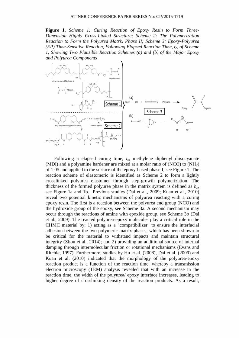
Figure 1. Scheme 1: Curing Reaction of Epoxy Resin to Form Three-
Dimension Highly Cross-Linked Structure; Scheme 2: The Polymerization
Reaction to Form the Polyurea Matrix Phase II; Scheme 3: Epoxy-Polyurea
(EP) Time-Sensitive Reaction, Following Elapsed Reaction Time, tc, of Scheme
1, Showing Two Plausible Reaction Schemes (a) and (b) of the Major Epoxy
and Polyurea Components
N R N
H
H
H
H
+
N R
X
X
N
X
X
H 3 C
O O O
C H 3
O H n+1
X =
H 3 C
O O O
C H 3
O O
O H
O
n
R =
H 2 C
O
C H 3
C H 2
O
C H 3
C H 3 m
diglycidal ether of Bisphenol A,
homopolymer
Where:
H C C H 3 3
Polyetheramine
N N C
O C
O
H 2 N O C H 2 C H
C H 3
N H 2 n
N
O
+
N O C H 2 C H
C H 3
N
H H
H H 2 C
C 6 H 4
N C O
C 6 H 4
N
H
O n
2 N O C H 2 C H
C H 3
n N
O
N
H H m
m m
bis(4-isocyanatophenyl)methane (MDI) diamine oligomer
H
E p o x y O H + N C O P o l y u r e a
E p o x y O
N C
O
P o l y u r e a
H
R N H 2 + C H
H 2 C
O =
H
N
O H
C H
H 2 C R
Scheme 1
Scheme 2
Scheme 3
(a)
(b)
Following a elapsed curing time, tc, methylene diphenyl diisocyanate
(MDI) and a polyamine hardener are mixed at a molar ratio of (NCO) to (NH2)
of 1.05 and applied to the surface of the epoxy-based phase I, see Figure 1. The
reaction scheme of elastomeric is identified as Scheme 2 to form a lightly
crosslinked polyurea elastomer through step-growth polymerization. The
thickness of the formed polyurea phase in the matrix system is defined as hp,
see Figure 1a and 1b. Previous studies (Dai et al., 2009; Kuan et al., 2010)
reveal two potential kinetic mechanisms of polyurea reacting with a curing
epoxy resin. The first is a reaction between the polyurea end group (NCO) and
the hydroxide group of the epoxy, see Scheme 3a. A second mechanism may
occur through the reactions of amine with epoxide group, see Scheme 3b (Dai
et al., 2009). The reacted polyurea-epoxy molecules play a critical role in the
CHMC material by: 1) acting as a "compatibilizer" to ensure the interfacial
adhesion between the two polymeric matrix phases, which has been shown to
be critical for the material to withstand impacts and maintain structural
integrity (Zhou et al., 2014); and 2) providing an additional source of internal
damping through intermolecular friction or rotational mechanisms (Evans and
Ritchie, 1997). Furthermore, studies by Hu et al. (2008), Dai et al. (2009) and
Kuan et al. (2010) indicated that the morphology of the polyurea-epoxy
reaction product is a function of the reaction time, whereby a transmission
electron microscopy (TEM) analysis revealed that with an increase in the
reaction time, the width of the polyurea/ epoxy interface increases, leading to
higher degree of crosslinking density of the reaction products. As a result,
ATINER CONFERENCE PAPER SERIES No: CIV2015-1719
fracture toughness of the polyurea/ epoxy system increased with an increase in
reaction time.
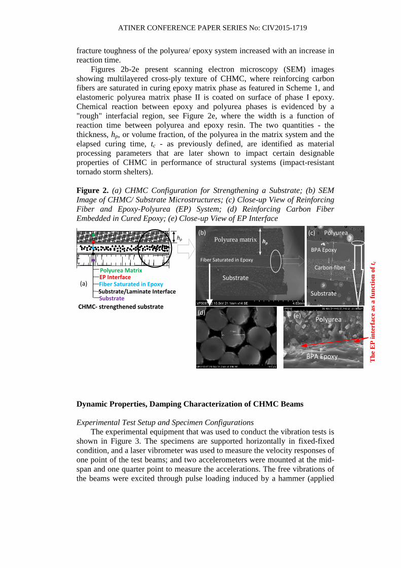
Figures 2b-2e present scanning electron microscopy (SEM) images
showing multilayered cross-ply texture of CHMC, where reinforcing carbon
fibers are saturated in curing epoxy matrix phase as featured in Scheme 1, and
elastomeric polyurea matrix phase II is coated on surface of phase I epoxy.
Chemical reaction between epoxy and polyurea phases is evidenced by a
"rough" interfacial region, see Figure 2e, where the width is a function of
reaction time between polyurea and epoxy resin. The two quantities - the
thickness, hp, or volume fraction, of the polyurea in the matrix system and the
elapsed curing time, tc - as previously defined, are identified as material
processing parameters that are later shown to impact certain designable
properties of CHMC in performance of structural systems (impact-resistant
tornado storm shelters).
Figure 2. (a) CHMC Configuration for Strengthening a Substrate; (b) SEM
Image of CHMC/ Substrate Microstructures; (c) Close-up View of Reinforcing
Fiber and Epoxy-Polyurea (EP) System; (d) Reinforcing Carbon Fiber
Embedded in Cured Epoxy; (e) Close-up View of EP Interface
Dynamic Properties, Damping Characterization of CHMC Beams
Experimental Test Setup and Specimen Configurations
The experimental equipment that was used to conduct the vibration tests is
shown in Figure 3. The specimens are supported horizontally in fixed-fixed
condition, and a laser vibrometer was used to measure the velocity responses of
one point of the test beams; and two accelerometers were mounted at the mid-
span and one quarter point to measure the accelerations. The free vibrations of
the beams were excited through pulse loading induced by a hammer (applied
(a)
hp hp
Polyurea
Polyurea
Substrate
BPA Epoxy
Carbon-fiber
buddle
(b) (c)
(d) (e)
Substrate
Polyurea matrix
Polyurea Matrix EP Interface Fiber Saturated in Epoxy
BPA Epoxy
CHMC- strengthened substrate
Substrate/Laminate Interface Substrate
Fiber Saturated in Epoxy
Th
e E
P i
nte
rfa
ce a
s a
fu
ncti
on
of
t c
ATINER CONFERENCE PAPER SERIES No: CIV2015-1719
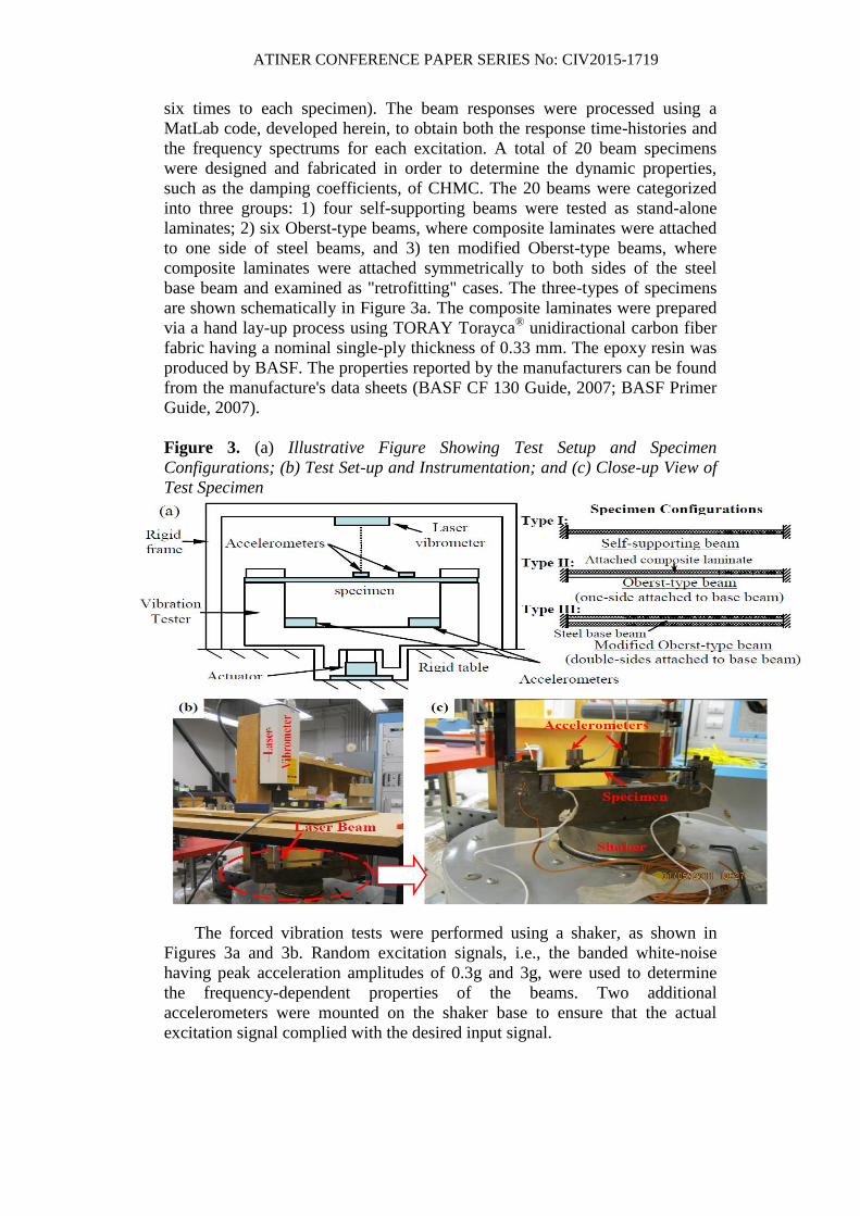
six times to each specimen). The beam responses were processed using a
MatLab code, developed herein, to obtain both the response time-histories and
the frequency spectrums for each excitation. A total of 20 beam specimens
were designed and fabricated in order to determine the dynamic properties,
such as the damping coefficients, of CHMC. The 20 beams were categorized
into three groups: 1) four self-supporting beams were tested as stand-alone
laminates; 2) six Oberst-type beams, where composite laminates were attached
to one side of steel beams, and 3) ten modified Oberst-type beams, where
composite laminates were attached symmetrically to both sides of the steel
base beam and examined as "retrofitting" cases. The three-types of specimens
are shown schematically in Figure 3a. The composite laminates were prepared
via a hand lay-up process using TORAY Torayca® unidiractional carbon fiber
fabric having a nominal single-ply thickness of 0.33 mm. The epoxy resin was
produced by BASF. The properties reported by the manufacturers can be found
from the manufacture's data sheets (BASF CF 130 Guide, 2007; BASF Primer
Guide, 2007).
Figure 3. (a) Illustrative Figure Showing Test Setup and Specimen
Configurations; (b) Test Set-up and Instrumentation; and (c) Close-up View of
Test Specimen
The forced vibration tests were performed using a shaker, as shown in
Figures 3a and 3b. Random excitation signals, i.e., the banded white-noise
having peak acceleration amplitudes of 0.3g and 3g, were used to determine
the frequency-dependent properties of the beams. Two additional
accelerometers were mounted on the shaker base to ensure that the actual
excitation signal complied with the desired input signal.
ATINER CONFERENCE PAPER SERIES No: CIV2015-1719
Experimental Analysis Method
Self-Supporting Beams
The governing equation of an un-damped uniform Euler-Bernoulli beam in
transverse free vibration may be written in the form of equation (1) as
4 2
4 2( , ) ( , ) 0
EI w wx t x t
A x t
(1)
where E is the Young's Modulus of the beam material, A and I are the area and
moment of inertia of the beam cross-section, respectively; ρ is the mass
density;; w(x,t) is the transverse deflection of the beam as a function of the
location x along the beam, and time t; (Rao, 2007). The solution of equation (1)
can be obtained by assuming the transverse displacement of the beam to be
( , ) ( ) ( )w x t W x T t (2)
then equation (1) becomes
4 2
2
4 2
1 1d W x d T tEI
A W x T tdx dt
(3)
Or
4
4
4
( )( ) 0
W x AW x
EIx
(4)
2
2
2
( )( ) 0
T tT t
t
(5)
where ω is the natural frequency. The solution of equation (6) may then be
expressed as
1 2
3 4
( ) cosh( ) cos( ) cosh( ) cos( )
sinh( ) sin( ) sinh( ) sin( )
W x C x x C x x
C x x C x x
(6)
where
4 2A
EI
(7)
and A, B, C1 ~ C4, are constants that may be determined by the imposing
boundary conditions. For lightly damped self-supporting uniform beams fixed
at both ends, see Figure 3a - type I, boundary conditions
(0) 0, (0) 0, ( ) 0, ( ) 0w w
w w L Lx x
may be substituted into equation (6),
leading to
cos( ) cosh( ) 1L L (8)
ATINER CONFERENCE PAPER SERIES No: CIV2015-1719
The approximate solution of equation (10) may be expressed as
2 1 2, 1,2,3...i L i i (9)
Recalling equation (7), the natural frequency of mode i may be calculated
as
2 42
42 , 1,2,3...
2 1i i
EIf i
ALi
(10)
where fi is natural frequency of mode i in Hz. For a viscoelastic beam subjected
to harmonic loading of frequency , elastic moduli of the materials may be
expressed as complex quantities
* ' 1E E i (11)
where E*ω is the complex Young's modulus of the beam material at frequency
ω; ηω is the loss factor associated to the dynamic Young's modulus (or storage
moduli) E'ω. Thus, the storage modulus of the beam material, Eω
', may be
expressed as a function of ωi, via equation (12)
2 4
'
4
2 1
i L AE
Ii
(12)
The loss modulus, Eω", is then calculated using the storage modulus and
the composite damping coefficient (or the loss factor) via equation (13) as
'' ' 'tan 2i iE E E (13)
where ηi and ξi are the loss factor and damping coefficient of mode i,
respectively.
Experimental measurements of the damping coefficient, ξ, or the loss
factor, η, may be evaluated using logarithm decrement method (when
analyzing free response data in time domain) via equation (14)
1
1
1ln
( 1) d n
x
n T x
(14)
where x1 are xn are the amplitudes of the first and nth
vibration cycles that are
used for the logarithm decrement calculation, ω1 is the natural frequency of
first mode vibration, expressed in rad/ sec, and Td is the period of vibration of
the first cycle of the damped response; or the half-power bandwidth method
(when analyzing response in the frequency domain) via equation (15)
ATINER CONFERENCE PAPER SERIES No: CIV2015-1719
0,2
i
i
i
f
f
(15)
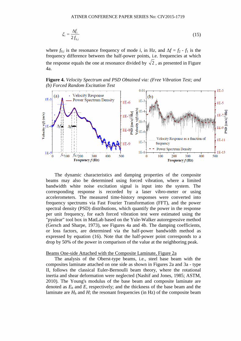
where f0,i is the resonance frequency of mode i, in Hz, and Δf = f2 - f1 is the
frequency difference between the half-power points, i.e. frequencies at which
the response equals the one at resonance divided by 2 , as presented in Figure
4a.
Figure 4. Velocity Spectrum and PSD Obtained via: (Free Vibration Test; and
(b) Forced Random Excitation Test
The dynamic characteristics and damping properties of the composite
beams may also be determined using forced vibration, where a limited
bandwidth white noise excitation signal is input into the system. The
corresponding response is recorded by a laser vibro-meter or using
accelerometers. The measured time-history responses were converted into
frequency spectrums via Fast Fourier Transformation (FFT), and the power
spectral density (PSD) distributions, which quantify the power in the response
per unit frequency, for each forced vibration test were estimated using the
"pyulear" tool box in MatLab based on the Yule-Walker autoregressive method
(Gersch and Sharpe, 1973), see Figures 4a and 4b. The damping coefficients,
or loss factors, are determined via the half-power bandwidth method as
expressed by equation (16). Note that the half-power point corresponds to a
drop by 50% of the power in comparison of the value at the neighboring peak.
Beams One-side Attached with the Composite Laminate, Figure 2a
The analysis of the Oberst-type beams, i.e., steel base beam with the
composites laminate attached on one side as shown in Figures 2a and 3a - type
II, follows the classical Euler-Bernoulli beam theory, where the rotational
inertia and shear deformation were neglected (Nashif and Jones, 1985; ASTM,
2010). The Young's modulus of the base beam and composite laminate are
denoted as Eb and E, respectively; and the thickness of the base beam and the
laminate are Hb and H; the resonant frequencies (in Hz) of the composite beam
ATINER CONFERENCE PAPER SERIES No: CIV2015-1719
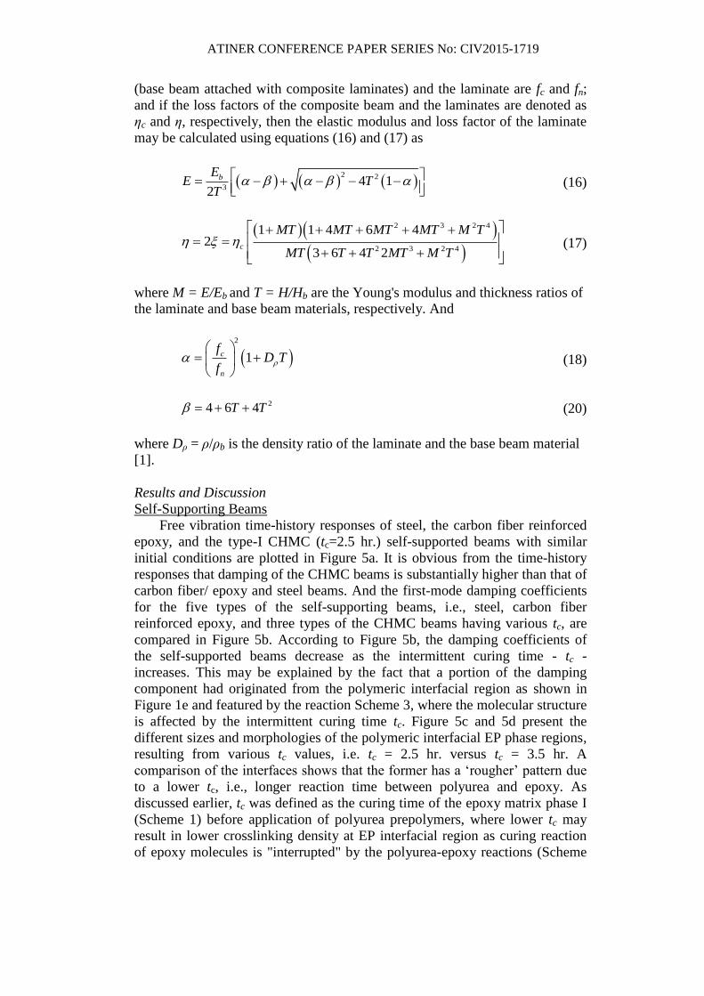
(base beam attached with composite laminates) and the laminate are fc and fn;
and if the loss factors of the composite beam and the laminates are denoted as
ηc and η, respectively, then the elastic modulus and loss factor of the laminate
may be calculated using equations (16) and (17) as
2 2
34 1
2
bEE T
T
(16)
2 3 2 4
2 3 2 4
1 1 4 6 42
3 6 4 2c
MT MT MT MT M T
MT T T MT M T
(17)
where M = E/Eb and T = H/Hb are the Young's modulus and thickness ratios of
the laminate and base beam materials, respectively. And
2
1c
n
fD T
f
(18)
24 6 4T T
(20)
where Dρ = ρ/ρb is the density ratio of the laminate and the base beam material
[1].
Results and Discussion
Self-Supporting Beams
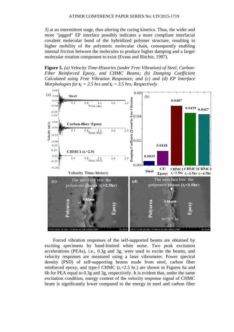
Free vibration time-history responses of steel, the carbon fiber reinforced
epoxy, and the type-I CHMC (tc=2.5 hr.) self-supported beams with similar
initial conditions are plotted in Figure 5a. It is obvious from the time-history
responses that damping of the CHMC beams is substantially higher than that of
carbon fiber/ epoxy and steel beams. And the first-mode damping coefficients
for the five types of the self-supporting beams, i.e., steel, carbon fiber
reinforced epoxy, and three types of the CHMC beams having various tc, are
compared in Figure 5b. According to Figure 5b, the damping coefficients of
the self-supported beams decrease as the intermittent curing time - tc -
increases. This may be explained by the fact that a portion of the damping
component had originated from the polymeric interfacial region as shown in
Figure 1e and featured by the reaction Scheme 3, where the molecular structure
is affected by the intermittent curing time tc. Figure 5c and 5d present the
different sizes and morphologies of the polymeric interfacial EP phase regions,
resulting from various tc values, i.e. tc = 2.5 hr. versus tc = 3.5 hr. A
comparison of the interfaces shows that the former has a ‘rougher’ pattern due
to a lower tc, i.e., longer reaction time between polyurea and epoxy. As
discussed earlier, tc was defined as the curing time of the epoxy matrix phase I
(Scheme 1) before application of polyurea prepolymers, where lower tc may
result in lower crosslinking density at EP interfacial region as curing reaction
of epoxy molecules is "interrupted" by the polyurea-epoxy reactions (Scheme
ATINER CONFERENCE PAPER SERIES No: CIV2015-1719
3) at an intermittent stage, thus altering the curing kinetics. Thus, the wider and
more "jagged" EP interface possibly indicates a more compliant interfacial
covalent molecular bond of the hybridized polymer structure, resulting in
higher mobility of the polymeric molecular chain, consequently enabling
internal friction between the molecules to produce higher damping and a larger
molecular rotation component to exist (Evans and Ritchie, 1997).
Figure 5. (a) Velocity Time-Histories (under Free Vibration) of Steel, Carbon-
Fiber Reinforced Epoxy, and CHMC Beams; (b) Damping Coefficient
Calculated using Free Vibration Responses; and (c) and (d) EP Interface
Morphologies for tc = 2.5 hrs and tc = 3.5 hrs, Respectively
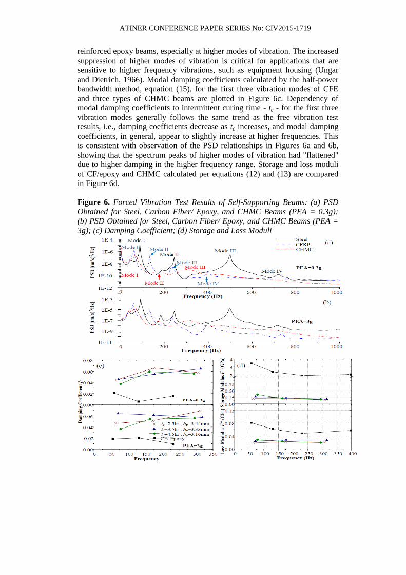
Forced vibration responses of the self-supported beams are obtained by
exciting specimens by band-limited white noise. Two peak excitation
accelerations (PEAs), i.e., 0.3g and 3g, were used to excite the beams, and
velocity responses are measured using a laser vibrometer. Power spectral
density (PSD) of self-supporting beams made from steel, carbon fiber
reinforced epoxy, and type-I CHMC (tc=2.5 hr.) are shown in Figures 6a and
6b for PEA equal to 0.3g and 3g, respectively. It is evident that, under the same
excitation condition, energy content of the velocity response signal of CHMC
beam is significantly lower compared to the energy in steel and carbon fiber
ATINER CONFERENCE PAPER SERIES No: CIV2015-1719
reinforced epoxy beams, especially at higher modes of vibration. The increased
suppression of higher modes of vibration is critical for applications that are
sensitive to higher frequency vibrations, such as equipment housing (Ungar
and Dietrich, 1966). Modal damping coefficients calculated by the half-power
bandwidth method, equation (15), for the first three vibration modes of CFE
and three types of CHMC beams are plotted in Figure 6c. Dependency of
modal damping coefficients to intermittent curing time - tc - for the first three
vibration modes generally follows the same trend as the free vibration test
results, i.e., damping coefficients decrease as tc increases, and modal damping
coefficients, in general, appear to slightly increase at higher frequencies. This
is consistent with observation of the PSD relationships in Figures 6a and 6b,
showing that the spectrum peaks of higher modes of vibration had "flattened"
due to higher damping in the higher frequency range. Storage and loss moduli
of CF/epoxy and CHMC calculated per equations (12) and (13) are compared
in Figure 6d.
Figure 6. Forced Vibration Test Results of Self-Supporting Beams: (a) PSD
Obtained for Steel, Carbon Fiber/ Epoxy, and CHMC Beams (PEA = 0.3g);
(b) PSD Obtained for Steel, Carbon Fiber/ Epoxy, and CHMC Beams (PEA =
3g); (c) Damping Coefficient; (d) Storage and Loss Moduli
ATINER CONFERENCE PAPER SERIES No: CIV2015-1719
Beams Having One-Side Attached to the Composite Laminate
When materials are used as retrofitting systems for a substrate, such as
steel or concrete, they are often applied as thin laminates or coatings. It is often
not feasible to test the dynamic properties of the retrofitting material system as
a self-supported system. In such cases, the retrofitting material can be attached
to one side (Oberst-type) or both sides (modified Oberst-type) of a base beam,
as shown Figure 3. The properties of the retrofitting laminate, such as the
smeared elastic modulus and damping coefficient (or loss factor), can be
determined from the dynamic responses of the composite beam and the base
beam according to equations (16)-(21).
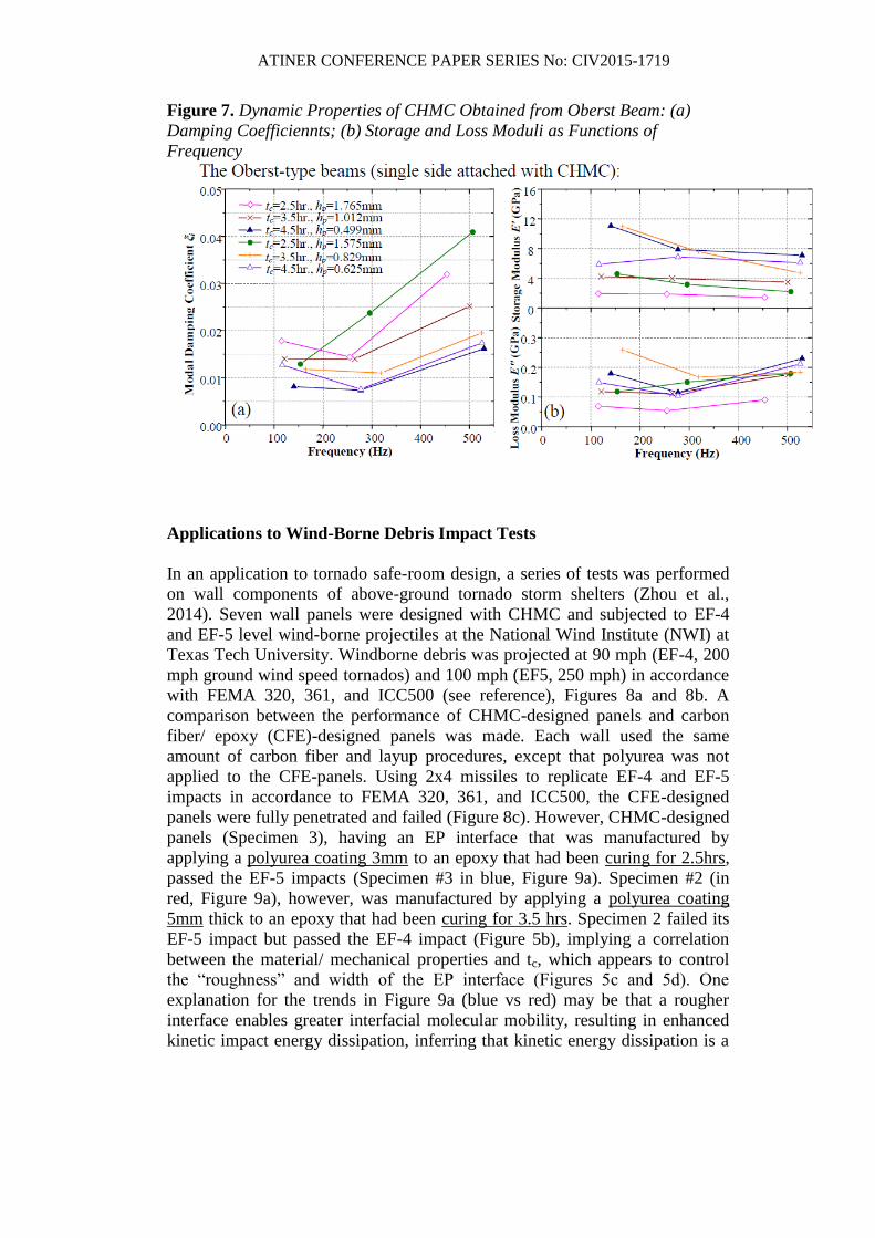
The calculated damping coefficient of the retrofitting laminate, ξ, based on
equation (17) for the Oberst-type beams are plotted in Figure 7a as functions of
frequency. Damping coefficients of the CHMC used as retrofitting laminates
are shown lower than those of self-supporting laminates due to the smaller
volume fraction of the high damping constituent - the polyurea matrix phase II,
since the elastomer can only be applied to one side of the retrofitting laminate.
Comparing the first mode damping coefficients of laminates having the same
tc, one can find that the damping coefficient is higher with a greater thickness
of the matrix phase II, i.e., higher hp. As mentioned in the previous sections,
the tc affects the morphology of the polyurea-epoxy interface, and in turn has
an impact on the damping the cohesion between this two matrix phases. The
differing interface morphologies have been demonstrated critical for impact
resistance of the composite (Zhou et al., 2014). The dependence of frequency
on the damping coefficients of the CHMC-retrofitted beams follows the same
trend as the self-supporting laminates, i.e., damping increases as the driving
frequency increases. This observation may be a result of the viscous properties
of the composite constituents, particularly polyurea. The storage and loss
moduli of the attached composite laminate may be calculated using the forced
vibration responses based on equations (12) and (13), respectively. The results
are plotted in Figure 7b.
ATINER CONFERENCE PAPER SERIES No: CIV2015-1719
Figure 7. Dynamic Properties of CHMC Obtained from Oberst Beam: (a)
Damping Coefficiennts; (b) Storage and Loss Moduli as Functions of
Frequency
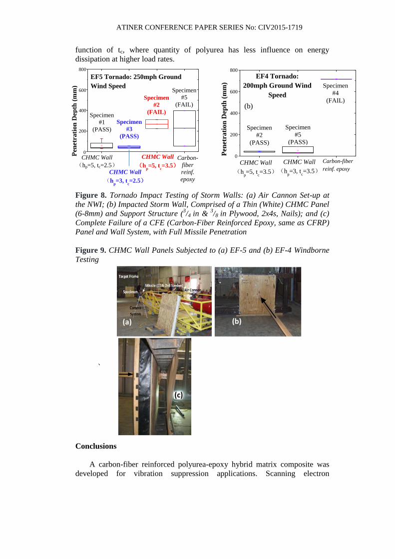
Applications to Wind-Borne Debris Impact Tests
In an application to tornado safe-room design, a series of tests was performed
on wall components of above-ground tornado storm shelters (Zhou et al.,
2014). Seven wall panels were designed with CHMC and subjected to EF-4
and EF-5 level wind-borne projectiles at the National Wind Institute (NWI) at
Texas Tech University. Windborne debris was projected at 90 mph (EF-4, 200
mph ground wind speed tornados) and 100 mph (EF5, 250 mph) in accordance
with FEMA 320, 361, and ICC500 (see reference), Figures 8a and 8b. A
comparison between the performance of CHMC-designed panels and carbon
fiber/ epoxy (CFE)-designed panels was made. Each wall used the same
amount of carbon fiber and layup procedures, except that polyurea was not
applied to the CFE-panels. Using 2x4 missiles to replicate EF-4 and EF-5
impacts in accordance to FEMA 320, 361, and ICC500, the CFE-designed
panels were fully penetrated and failed (Figure 8c). However, CHMC-designed
panels (Specimen 3), having an EP interface that was manufactured by
applying a polyurea coating 3mm to an epoxy that had been curing for 2.5hrs,
passed the EF-5 impacts (Specimen #3 in blue, Figure 9a). Specimen #2 (in
red, Figure 9a), however, was manufactured by applying a polyurea coating
5mm thick to an epoxy that had been curing for 3.5 hrs. Specimen 2 failed its
EF-5 impact but passed the EF-4 impact (Figure 5b), implying a correlation
between the material/ mechanical properties and tc, which appears to control
the “roughness” and width of the EP interface (Figures 5c and 5d). One
explanation for the trends in Figure 9a (blue vs red) may be that a rougher
interface enables greater interfacial molecular mobility, resulting in enhanced
kinetic impact energy dissipation, inferring that kinetic energy dissipation is a
ATINER CONFERENCE PAPER SERIES No: CIV2015-1719
function of tc, where quantity of polyurea has less influence on energy
dissipation at higher load rates.
Figure 8. Tornado Impact Testing of Storm Walls: (a) Air Cannon Set-up at
the NWI; (b) Impacted Storm Wall, Comprised of a Thin (White) CHMC Panel
(6-8mm) and Support Structure (3/4 in &
3/8 in Plywood, 2x4s, Nails); and (c)
Complete Failure of a CFE (Carbon-Fiber Reinforced Epoxy, same as CFRP)
Panel and Wall System, with Full Missile Penetration
Figure 9. CHMC Wall Panels Subjected to (a) EF-5 and (b) EF-4 Windborne
Testing
Conclusions
A carbon-fiber reinforced polyurea-epoxy hybrid matrix composite was
developed for vibration suppression applications. Scanning electron
CHMC Wall
(hp=5, tc=2.5)
0
200
400
600
800
Carbon-
fiber
reinf.
epoxy
Specimen
#1
(PASS)
Specimen
#3
(PASS)
Specimen
#2
(FAIL)
Specimen
#5
(FAIL)
CHMC Wall
(hp=3, t
c=2.5)
CHMC Wall
(hp=5, t
c=3.5)
Pen
etra
tio
n D
epth
(m
m)
EF5 Tornado: 250mph Ground
Wind Speed
0
200
400
600
800
Specimen
#4
(FAIL)
Specimen
#2
(PASS)
Specimen
#5
(PASS)
Carbon-fiber
reinf. epoxy
CHMC Wall
(hp=3, t
c=3.5)
CHMC Wall
(hp=5, t
c=3.5)
Pen
etra
tio
n D
epth
(m
m)
EF4 Tornado:
200mph Ground Wind
Speed
(b)
(a)
(b)
(c)
(
a)
ATINER CONFERENCE PAPER SERIES No: CIV2015-1719
microscopy (SEM) images showing microstructures of the CHMC are
presented. A multilayered cross-ply texture was evidenced by SEM images,
and micromechanical properties of the constituents were studied using
nanoindentation tests; the cross-ply modulus profile of the CHMC laminate
was obtained, and nanoindentation results indicate substantial hysteretic
damping properties of the matrix constituents, where crosslinking reaction of
the epoxy phase was altered by adding polyurea phase. Reaction between
epoxy and polyurea (EP) phases formed a well-bonded interface, which is
believed to provide substantial additional internal damping for the CHMC.
Dynamic properties of the CHMC and conventional carbon fiber
reinforced epoxies (CF/ epoxy) are investigated using free vibration and forced
vibration tests. Natural frequencies and damping coefficients were calculated
using vibration responses of tested beams. CHMC exhibits enhanced damping
and vibration suppression capability than the conventional CF/ epoxy both as a
stand-alone structural material and as a retrofitting system. In general, the
observed damping is higher when used as a stand-alone laminate than as a
retrofitting material. This may be attributed to the single-side coated lay-up of
the retrofitting laminates, thus, the lower volume fraction of the polyurea
phase. The influence of the two material processing parameters - hp and tc - on
the material damping was investigated, and the results reveal that, generally,
the damping coefficients increase with greater hp and smaller tc. Damping
based design of CHMC is facilitated through material processing parameters,
including matrix phase II thickness - hp - and intermittent curing time - tc, -
which impact its material properties.
References
Agarwal B., Broutman L. J. and Chandrashekhara K. Analysis and performance of
fiber composites. 3rd
Edition ed. New York, NY: Jon Wiley & Sons; 2006.
ASTM E756-05. Standard test method for measuring vibration-damping properties of
materials. West Conshohocken, PA: ASTM; 2010.
BASF Mbrance CF 130 Data Guide. Shakopee, MN: BASF Construction Chemicals,
LLC - Building Systems; 2007.
BASF Mbrace Primer Data Guide. Shakopee, MN: BASF, The Chemical Company;
2007.
Berthelot J. M. and Sefrani Y. Damping analysis of unidirectional glass and Kevlar
fibre composites. Comp Sci & Tech 2003;64:1261-78.
Cawse J. L., Stanford J. L. Rubber-toughened polyurethane network and composite
mateirals. Polymer 1987;28:356-67.
Dai J. B., Kuan H. C., Du X. S., Dai S. C. and Ma J. Development of a novel
toughener for epoxy resins. Polym Int 2009;58:838-45.
Evans E. and Ritchie K. Dynamic strength of molecular adhesion bonds. Biophys J
1997;72(4):1541-55.
Federal Emergency Management Agency. Taking shelter from the storm: building a
safe room for your home or small business. FEMA P-320. Washington DC; 2008.
Federal Emergency Management Agency. Design and construction guidance for
community safe rooms. FEMA P-361. Washington DC; 2008.
ATINER CONFERENCE PAPER SERIES No: CIV2015-1719
Gersch W. and Sharpe D. R. Estimation of power spectra with finite-order
autoregression models. IEEE Trans Automat Contr 1973;18(4):367-9.
Hu H., Yu S., Wang M., Ma J. and Liu K. Tribological properties of epoxy/ polyurea
composite. Polymers for Advanced Technologies 2008; 20: 748-52.
International Code Concil & National Storm Shelter Association. NSSA standard for
the design and construction of storm shelters. ICC500; 2008.
Kuan H. C, Dai J. B. and Ma J. A reactive polymer for toughening epoxy resin. J Appl
Polym Sci 2010;115:3265-72.
Lakes R. S. High damping composite materials: effect of structural hierarchy. J
Compos Mater 2002;36(3):287-97.
Nashif A. D., Jones D. I. G. and Henderson J. P. Vibration damping. New York, NY:
Jonh Wiley & Sons; 1985.
Rao S. S. Vibration of continous systems. New York, NY: John Wiley & Sons; 2007.
Tsai J. L., Huang B. H. and Cheng Y. L. Enhancing fracture toughness of glass/epoxy
composites by using rubber particles together with silica nanoparticles. J Comp
Mater 2009;43(25):3107-23.
Zhou H. and Attard T. L. Rehabilitation and strength sustainability of fatigue damaged
concrete-encased steel flexural members using a newly developed polymeric
carbon-fiber composite. Comp Part B: Eng 2013;45:1091-103.
Zhou H., Attard T. L., Wang Y. L., Wang J. A. and Ren F. Rehabilitation of notch
damaged steel beams using a carbon fiber reinforced hybrid polymeric-matrix
composite. Compos Struct 2013;106:690-702.
Zhou H., Dhiradhamvit K. and Attard T. L. Tornado-borne debris impact performance
of an innovative storm safe room system protected by a carbon fiber reinforced
hybrid-polymer matrix composite. Engineering Structures 2014;59:308-19.
Ungar E. E. and Dietrich C. W. High-frequency vibration isolation. J Sound Vib
1966;4(2):224-41.


![Daniel Defoe 1719 [Robinson Crusoe]](https://img.pdfslide.us/doc/110x75/577d2baa1a28ab4e1eab0991/daniel-defoe-1719-robinson-crusoe.jpg)


![1719. MANAGEMENT INFORMATION SYSTEM [HCL] [IT]](https://img.pdfslide.us/doc/110x75/55178231497959a8308b4ac2/1719-management-information-system-hcl-it.jpg)