Embed Size (px)
Citation preview

ATH 1300/1600 M-MTMAGLEV HYBRID TURBOMOLECULAR PUMPS
User’s Manual

GB
0077
9 –
Ed 0
2 -
Mar
ch 0
4
Alcatel Vacuum Technology, as part of the AlcatelGroup, has been supplying vacuum pumps, leakdetection systems, vacuum measurement and micromachining systems.Thanks to its complete range of products, thecompany has become an essential player in multipleapplications : instrumentation, Research &Developement, industry and semiconductors.
Alcatel Vacuum Technology has launched Adixen, itsnew brand name, in recognition of the company’sinternational standing in vacuum position.With both ISO 9001 and 14001 certifications, theFrench company is an acknowlegded expert in serviceand support, and Adixen products have the highestquality and environmental standards.
With 40 years of experience, AVT today has aworldwide presence, through its international networkthat includes a whole host of experienced subsidiaries,distributors and agents.The first step was the founding of Alcatel VacuumProducts (Hingham- MA) in the United States, thirtyyears ago, reinforced today by 2 others USsubsidiaries in Fremont (CA) and Tempe (AZ).In Europe, AVTF-France headquarters and three of itssubsidiaries, Alcatel Hochvakuumtechnik (Germany),Alcatel Vacuum Technology UK (Scotland) and AlcatelVacuum Systems (Italy) form the foundation for theEuropean partner network.In Asia, our presence started in 1993 with AlcatelVacuum Technology (Japan), and has beenstrengthened with Alcatel Vacuum Technology Korea(in 1995), Alcatel Vacuum Technology Taïwan (in2001), Alcatel Vacuum Technology Singapore, andmore recently with Alcatel Vacuum TechnologyShanghai (China) (in 2004).This organization is rounded off by more than 40represensatives based in a variety of continents.
Thus, whatever the circumstances, the users ofAdixen products can always rely on quicksupport of our specialists in VacuumTechnology.

Alcatel Vacuum Technology France - User’s ATH 1300 M/MT - ATH 1600 M/MT
ATH 1300 M/MT - ATH 1600 M/MTMaglev hybrid turbomolecular pumps
Welcome
1/2
GB
0072
0 -
Editi
on 0
8 -
Janu
aray
04
APPLICATIONS:
SEMICONDUCTOR APPLICATIONSPlasma etching, Ion implantation, Sputtering,Plasma deposition.
OTHERS APPLICATIONSElectron microscopes, Surface analysis,Research and development, High energy physics,Space simulation, Accelerators.
ADVANTAGES:High throughput - Quiet and clean vacuum - Corrosionproof - High MTBF - Minimum size, volume and weight -Smart and compact electronic controller - Reliability -Maintenance free - Battery free - Easy integration.
Dear Customer,
You have just purchased anAlcatel maglev hybrid turbopump.We would like to thank youand are proud to count youas one of our customers.
This product has benefitedfrom Alcatel’s many yearsof experience in the field of turbomolecular pumpdesign.
In order to ensure the bestpossible performance of the equipment and yourcomplete satisfaction inusing it, we advise you toread this manual carefullybefore any intervention onyour pump and to payparticular attention to the equipment installationand start-up section.
MANUAL REFERENCE: 105 677EDITION: 12 - JANUARY 2004

Alcatel Vacuum Technology France - User’s Manual ATH 1300 M/MT - 1600 M/MT
ATH 1300 M/MT - ATH 1600 M/MTMaglev hybrid turbomolecular pumps
1/2
GB
0072
0 -
Editi
on 0
8 -
Janu
ary
04
This product complies with the requirements of EuropeanDirectives, listed in the Declaration of Conformity contained inG100 of this Manual. These Directives are amended byDirective 93/68/E.E.C (E.C. Marking).
Copyright/Intellectual property:The use of Alcatel products are subject to copyright and intellectual property rights in force in any jurisdisction.All rights reserved, including copying this document in wholeor any part without prior written authorization from AlcatelVacuum Technology France.Specifications and information are subject to change withoutnotice by from Alcatel Vacuum Technology France.
Contents
Alcatel Vacuum Technology France - User’s Manual ATH 1300 M/MT - ATH 1600 M/MT
User’s Manual ATH 1300 M/MT - 1600 M/MT
GB
0072
1 -
Editi
on 1
2 -
Janu
ary
04
1/2
Introduction
Start-up
Introduction to the ATH 1300 M/MT - 1600 M/MT and associated ACT controller . . .
The pump operating principle . . . . . . . . . . . .
Pump overview . . . . . . . . . . . . . . . . . . . . .
ACT 1300 M controller. . . . . . . . . . . . . . . . .
The accessories . . . . . . . . . . . . . . . . . . . . .
The technical characteristics . . . . . . . . . . . . .
Certificate of compliance SEMI S2-93 A . . . . .
Safety instructions . . . . . . . . . . . . . . . . . . . .
Unpacking and storage . . . . . . . . . . . . . . . .
Pump connections to an installation . . . . . . . .
Inlet and exhaust connections . . . . . . . . . . . .
Air inlet valve connection (option) . . . . . . . . . . .
Nitrogen purge device connection . . . . . . . . .
Water cooling connection . . . . . . . . . . . . . . .
Heating band connection . . . . . . . . . . . . . . .
Electrical connections . . . . . . . . . . . . . . . . . .
«Dry contacts» connector wiring . . . . . . . . . .
«Inputs/Outputs» connector wiring . . . . . . . . .
«Rem.» connector wiring . . . . . . . . . . . . . . .
RS 232 or RS 485 serial link wiring . . . . . . . .
Detailed description of RS commands . . . . . . .
A 10
A 20
A 30
A 40
A 50
A 60
A 70
B 10
B 20
B 30
B 31
B 40
B 50
B 60
B 70
B 80
B 90
B 91
B 100
B 110
B120

Contents
Alcatel Vacuum Technology France - User’s Manual ATH 1300 M/MT - ATH 1600 M/MT
User’s Manual ATH 1300 M/MT - 1600 M/MT
GB
0072
1 -
Editi
on 1
2 -
Janu
ary
04
Cautions are used when failure to observe instructions could result in significant damage toequipment and/or facilities.
2/2
Operation
Maintenance
Maintenance instructions
Maintenance components
Appendix
CAUTION!
Warnings are used when failure to observe instructionscould result in injury or death
WARNING
Safety instructions . . . . . . . . . . . . . . . . . . . . . .
Controller start-up . . . . . . . . . . . . . . . . . . . . . .
Configuring the controller for the application . . .
Controlling the pump using the controller front panel
“Local” and “Remote” mode operation. . . . . . . .
«Ext. safety» contact operation . . . . . . . . . . . . .
“INH” inhibit mode operation. . . . . . . . . . . . . .
Safety instructions . . . . . . . . . . . . . . . . . . . . . .
Diagnosis and Troubleshooting . . . . . . . . . . . . .
Shipping procedure for contaminated pumps . . .
Spare parts - Instructions of use . . . . . . . . . . . .
First level maintenance parts . . . . . . . . . . . . . .
Pumping curves . . . . . . . . . . . . . . . . . . . . . . .
Safety questionnaire . . . . . . . . . . . . . . . . . . . .
Declaration of conformity . . . . . . . . . . . . . . . . .
C 10
C 20
C 30
C 40
C 50
C 60
C 70
D 10
D 20
E 00
F 00
F 10
G 10
G 11
G 100

1/2
GB
0072
3 -
Editi
on 0
5 -
Janu
ary
01
Alcatel Vacuum Technology France - User’s Manual ATH 1300 M/MT - ATH 1600 M/MT
A 10Introduction to the ATH 1300 M/MT - ATH 1600 M/MTand associated ACT controller
ATH 1300 MATH 1600 M
1 magnetically levitatedhybrid turbo pump
Five active axesACTIDYNE® Maglev bearings type (S2M Patent)Rotor position control in5 directions.
Automatic balancing systemLowest possible levels ofnoise and vibration.Compensation for anyimbalance of the rotor.
Maintenance free
Inert gas purgeEliminate corrosion ofthe motor and magneticbearing coils.
Battery freeIn case of a power failure,the pump motor acts likea generator to transformthe rotor energy intoelectrical power to supplythe controller.
ATH 1300 MTATH 1600 MT
Integral heater bandMaintaining the pumps internal surface up to 75°Cto prevent the condensation effect.Temperature regulated by the ACT controller, or bythe customer device.

2/2
GB
0072
3 -
Editi
on 0
5 -
Janu
ary
01
Alcatel Vacuum Technology France - User’s Manual ATH 1300 M/MT - ATH 1600 M/MT
A 10Introduction to the ATH 1300 M/MT - ATH 1600 M/MTand associated ACT controller
ACT 1300 M controller
The new generation ofACT controller family
Especially designed for maglev turbopumpsLight and small controllers.Battery free.Automatically detects and operates the ATH 1300 M/MTor ATH 1600 M/MT.
Convenient interfaceHandy keyboard;Alphanumeric display.
Modern pump monitoringMonitoring of testing and troubleshooting parameters;RS 232/485 serial links;Automatic power supply detection from 100 V -15% to120 V +10% and from 200 V -15% to 240 V +10%,48/63 Hz single phase.
Power supply for heater: 100-120/200-240 V - 50/60 HzATH 1300 MT: 200 WATH 1600 MT: 135 W
Large range of interfaceDry contacts interface for status signals and optocoupledcontrol inputs;Selectable Analog 0-10 V output.

A 20The pump operating principle
1/4
GB
0072
4 -
Editi
on 0
5 -
Janu
ary
04
Alcatel Vacuum Technology France - User’s Manual ATH 1300 M/MT - ATH 1600 M/MT
A hybrid technology The ATH 1300 M and the ATH 1600 M integrate the advantages of a multi-staged turbomolecular pump with a spiral helix molecular drag section to enhance ultra high-vacuum (UHV) and ultra clean technology (UCT).
The turbomolecular section provides high pumping speedsand UHV ultimate vacuum.The molecular drag section provides a high compressionratio and extends forevacuum tolerance up to 1.5 mbar.
Inlet
Magneticlevitatedbearings
Gas purgeCooling
Moleculardrag
Stator
Rotor
Motor
Dry back-upbearings
Exhaust

A 20The pump operating principle
2/4
GB
0072
4 -
Editi
on 0
5 -
Janu
ary
04
Alcatel Vacuum Technology France - User’s Manual ATH 1300 M/MT - ATH 1600 M/MT
5 actives axis The mobile assembly formed by the turbo rotor andthe shaft is known as the rotor. This rotor is driven bythe motor and held in suspension by magnetic fieldsgenerated by electromagnets housed in active bearing,type ACTIDYNE® maglev bearing (S2M Patent).The mobile rotor has five axes of freedom monitored by5 active bearings.
+Rotor
Stator
BearingElectronics
Poweramplifiers
Referencesignal
Detector signalElectro-magnet
Positiondetector
+Signalprocessing+
Z
X
XY
Y
Movements in relation to these axes are monitored byposition sensors. According to the position data recorded,the ACT controller corrects differences to bring the rotorback to its optimum position, by varying the current inelectro-magnets.
3 controlled translations (X, Y, Z)
2 controlled rocking (X, Y)

A 20The pump operating principle
3/4
GB
0072
4 -
Editi
on 0
5 -
Janu
ary
04
Alcatel Vacuum Technology France - User’s Manual ATH 1300 M/MT - ATH 1600 M/MT
Automatic BalancingSystem
The back-up bearings
No maintenance
Battery free
The Automatic Balancing System is an electronic device.That monitors the rotor position, allowing it to rotate onits own axis of inertia.Changes in the rotor balance, due to deposit built-upduring the life time of the pump, are automaticallycompensated by the Automatic Balancing System.Therefore, there is a total absence of vibration.
They are dry-lubricated ceramic ball bearings.They are never used in normal operation, since the rotoris not in contact with the bearings.The back-up bearings are only used to protect the pump inaccidental air in-rushes, accidental shocks or power failure.
By design, the pump doesn’t include parts liable to wearand doesn’t need preventive maintenance. However, theback-up bearings used in case of accidental shut-downshave to be changed when the controller indicates it: thepercentage of landing time to be deducted depends on itsfrequency of use (see D 10).
In case of a power failure, the motor acts like a generator,supplying enough power for the magnetic bearings.When the rotation speed is lower than the minimum setpoint,the pump lands and shuts down on the back-up bearings.
Rotor geometric axisStator geometric axisRotor inertia axis

4/4
GB
0072
4 -
Editi
on 0
5 -
Janu
ary
04
Alcatel Vacuum Technology France - User’s Manual ATH 1300 M/MT - ATH 1600 M/MT
A 20The pump operating principle
The hybrid-turbo pumpin an installation
At the pump exhaust, the gases are evacuated toatmosphere by a primary pump.Since the ATHM compression ratio is set by the design,the ATHM limit pressure is given by that of the primarypump used.
Chamberto be
pumped
Secondarypumping
INLETPRESSURE
ATMOSPHERICPRESSURE
Primarypumping
Primary vacuumSecondary vacuum
A 30Pump overview
1/2
GB
0072
5 -
Editi
on 0
5 -
Janu
ary
04
Alcatel Vacuum Technology France - User’s Manual ATH 1300 M/MT - ATH 1600 M/MT
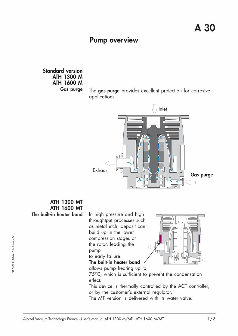
Standard versionATH 1300 MATH 1600 M
Gas purge
ATH 1300 MTATH 1600 MT
The built-in heater band
Inlet
Gas purgeExhaust
The gas purge provides excellent protection for corrosiveapplications.
In high pressure and highthroughtput processes suchas metal etch, deposit canbuild up in the lowercompression stages ofthe rotor, leading thepumpto early failure.The built-in heater bandallows pump heating up to75°C, which is sufficient to prevent the condensationeffect.This device is thermally controlled by the ACT controller,or by the customer’s external regulator.The MT version is delivered with its water valve.
A 30Pump overview
2/2
GB
0072
5 -
Editi
on 0
5 -
Janu
ary
04
Alcatel Vacuum Technology France - User’s Manual ATH 1300 M/MT - ATH 1600 M/MT
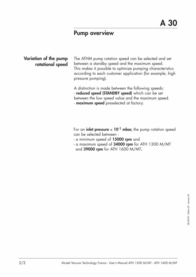
Variation of the pumprotational speed
The ATHM pump rotation speed can be selected and setbetween a standby speed and the maximum speed.This makes it possible to optimize pumping characteristicsaccording to each customer application (for example, highpressure pumping).
A distinction is made between the following speeds:- reduced speed (STANDBY speed) which can be setbetween the low speed value and the maximum speed.- maximum speed preselected at factory.
For an inlet pressure ≤ 10-1 mbar, the pump rotation speedcan be selected between :- a minimum speed of 15000 rpm and - a maximum speed of 34000 rpm for ATH 1300 M/MTand 39000 rpm for ATH 1600 M/MT.
1/2
GB
0072
6 -
Editi
on 0
3 -
Janu
ary
01
Alcatel Vacuum Technology France - User’s Manual ATH 1300 M/MT - ATH 1600 M/MT
A 40ACT 1300 M controller
Compact and functional
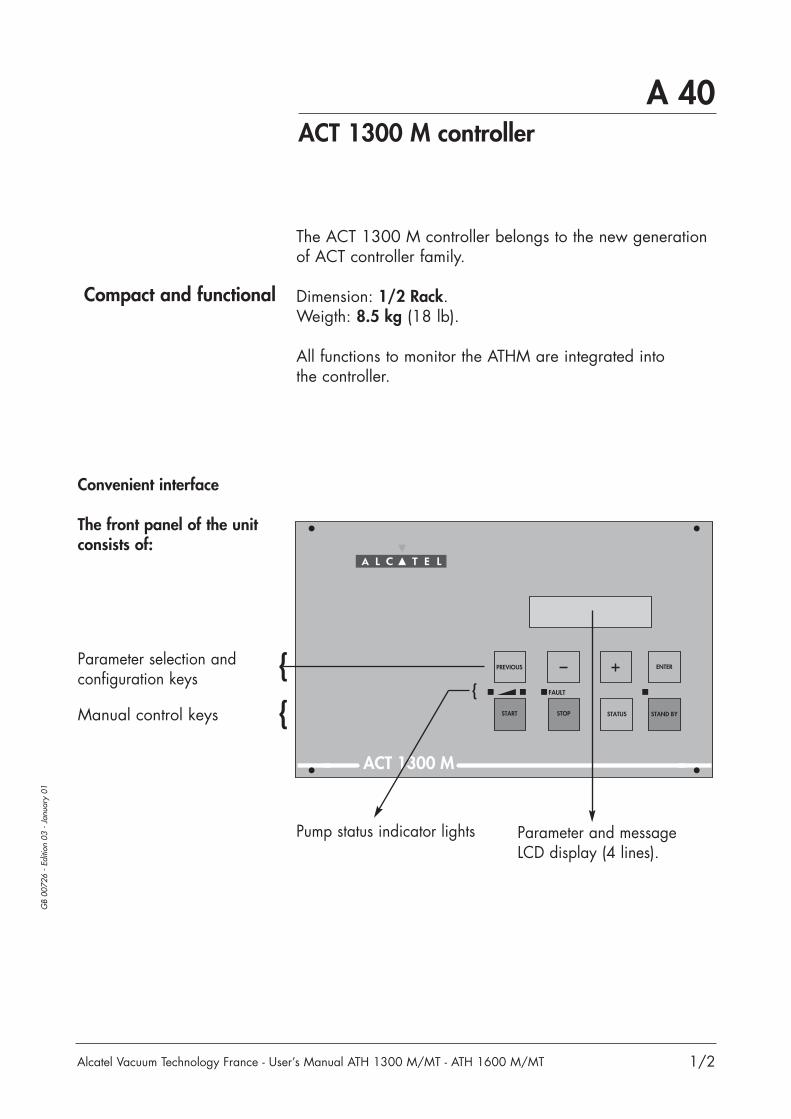
The ACT 1300 M controller belongs to the new generationof ACT controller family.
Dimension: 1/2 Rack.Weigth: 8.5 kg (18 lb).
All functions to monitor the ATHM are integrated intothe controller.
START STOP STATUS STAND BY
ENTERPREVIOUS
ACT 1300 M
FAULT
Convenient interface
The front panel of the unitconsists of:
Parameter selection andconfiguration keys
Manual control keys
Parameter and messageLCD display (4 lines).
Pump status indicator lights

2/2
GB
0072
6 -
Editi
on 0
3 -
Janu
ary
01
Alcatel Vacuum Technology France - User’s Manual ATH 1300 M/MT - ATH 1600 M/MT
A 40ACT 1300 M controller
PUMP CABLE
REM.
DRY CONTACTS
RS 232
0 1The rear panel of the unit
consists of:
1 Power supply connector
2 Pump connector
3 Relay terminal strip(Wiring characteristicson B 90.)
4 Analog output andRS 485 serial link(Wiring characteristicson B 100.)
5 RS 232 connector(Wiring characteristicson B 110.)
6 Inputs, outputsconnector
(Wiring instructionson B 91.)
7 Grounding
1
6
57
23
4
- to replicate the monitoring parameters available in theform of dry contacts.
- selectable 0 - 10 Volts output for speed, pump current ortemperature;
RS485 serial link allowing many pump installations in anetwork.
The RS 232 serial link is used to control and monitor thepump using a computer.
- For the remote control of START/STOP/STANBY/INHIBITfunctions,
- to take in account external safety,- to allow dry contact outputs.
Allow the fixation of a grounding cable to connect thecontroller at the ground and to connect the groundingcables of the accessories (water valve, air inlet valvecable).

A 50The accessories
1/2
GB
0172
4 -
Editi
on 0
9 -
Janu
ary
04
Alcatel Vacuum Technology France - User’s Manual ATH 1300 M/MT - ATH 1600 M/MT
Flow Reduction device DN 16
Flow rate P.N.
25 SCCM 066950
50 SCCM* 066752
* delivered with air inlet valve
See the Alcatel catalog.
Pump accessoriesScreen filter This filter protects the pump against solid particles.
Mesh size 3.5 mm. It is integrated into the pump housing.
This device is used toreduce the purge gas flow rate in someprocesses.
Purge flow reduction device
Isolation valveat inlet pump
The secondary isolationvalve is used to maintainthe vacuum in the chamberwhile the pump is reset toatmospheric pressure.
Air inlet valveand cable
This valve will slow downthe pump in complete safety.With this option, the brakingtime from nominal speed to0 rpm is t < 15 mn.Without this accessory, thebraking time is about 30 mn.(See B 40 for valve installation).
DN 200 ISO (S.Steel) P.N.Standard filter + standard clip 107824Convexe filter + bored clip 108872Removable filter + standard clip 104907
DN 250 ISOConvexe filter (alu) + standard clip 109199Convexe filter (S.Steel) + standard clip 108762
Air inlet valve P.N.12 VDC 106866Air inlet cableLength P.N.1 m 1060523.5 m 1051725 m 10517310 m 10517415 m 10517520 m A459362
An entire range of connection accessories is available in the Alcatel catalog (clampingring, centering ring, etc.).

A 50The accessories
2/2
GB
0172
4 -
Editi
on 0
9 -
Janu
ary
04
Alcatel Vacuum Technology France - User’s Manual ATH 1300 M/MT - ATH 1600 M/MT
Connection cable
Thermostatic cable
Controller accessories
Interconnecting cable between heater band and controller.This cable includes water valve cable.
Interconnecting cablebetween pump andcontroller.
Length P.N.
1 m 104624
3.5 m 103719
5 m 103720
10 m 103721
15 m 104587
20 m A214574
Length P.N.
1 m 110 V A328698A
3.5 m 110 V A328698B
5 m 110 V A328698C
10 m 110 V A328698D
15 m 110 V A328698E
20 m 110 V A328698F
Length P.N.
1 m 230 V A328697A
3.5 m 230 V A328697B
5 m 230 V A328697C
10 m 230 V A328697D
15 m 230 V A328697E
20 m 230 V A328697F
Power line cable Cable to connect thecontroller to the powersupply.
Length P.N.
2.5 m US A328406
2.5 m EUROPE A328405
The thermostatic cable must be connected to a 4 A circuitbreaker on the two phases.
A 60The technical characteristics
1/5
GB
0072
8 -
Editi
on 0
8 -
Janu
ary
04
Alcatel Vacuum Technology France - User’s Manual ATH 1300 M/MT - ATH 1600 M/MT
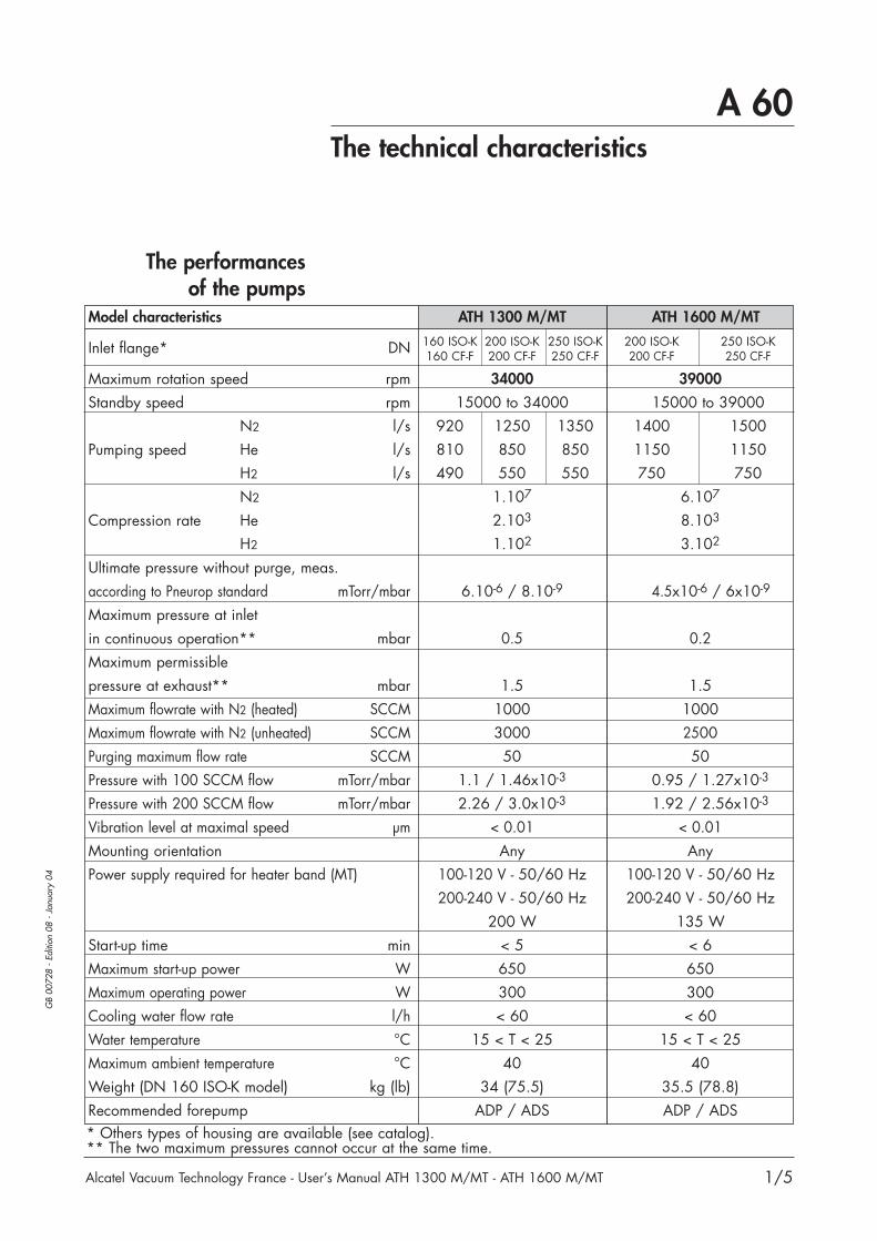
The performancesof the pumps
* Others types of housing are available (see catalog).** The two maximum pressures cannot occur at the same time.
Model characteristics ATH 1300 M/MT
Inlet flange* DN 160 ISO-K 200 ISO-K 250 ISO-K160 CF-F 200 CF-F 250 CF-F
Maximum rotation speed rpm 34000
Standby speed rpm 15000 to 34000N2 l/s 920 1250 1350
Pumping speed He l/s 810 850 850H2 l/s 490 550 550N2 1.107
Compression rate He 2.103
H2 1.102
Ultimate pressure without purge, meas.according to Pneurop standard mTorr/mbar 6.10-6 / 8.10-9
Maximum pressure at inletin continuous operation** mbar 0.5Maximum permissiblepressure at exhaust** mbar 1.5Maximum flowrate with N2 (heated) SCCM 1000Maximum flowrate with N2 (unheated) SCCM 3000Purging maximum flow rate SCCM 50Pressure with 100 SCCM flow mTorr/mbar 1.1 / 1.46x10⁻³
Pressure with 200 SCCM flow mTorr/mbar 2.26 / 3.0x10⁻³
Vibration level at maximal speed µm < 0.01Mounting orientation AnyPower supply required for heater band (MT) 100-120 V - 50/60 Hz
200-240 V - 50/60 Hz200 W
Start-up time min < 5Maximum start-up power W 650Maximum operating power W 300Cooling water flow rate l/h < 60Water temperature °C 15 < T < 25Maximum ambient temperature °C 40Weight (DN 160 ISO-K model) kg (lb) 34 (75.5)Recommended forepump ADP / ADS
ATH 1600 M/MT
200 ISO-K 250 ISO-K200 CF-F 250 CF-F
39000
15000 to 390001400 15001150 1150750 750
6.107
8.103
3.102
4.5x10⁻⁶ / 6x10⁻⁹
0.2
1.51000250050
0.95 / 1.27x10⁻³
1.92 / 2.56x10⁻³
< 0.01Any
100-120 V - 50/60 Hz200-240 V - 50/60 Hz
135 W< 6650300< 60
15 < T < 2540
35.5 (78.8)ADP / ADS

A 60The technical characteristics
2/5
GB
0072
8 -
Editi
on 0
8 -
Janu
ary
04
Alcatel Vacuum Technology France - User’s Manual ATH 1300 M/MT - ATH 1600 M/MT
Controller characteristics11
2.5
150
49
237
54.75
453408
109.5
219
M 4
132.
5
122.
45
ACT 1300 M
PREVIOUS ENTER+
STAND BYSTATUSSTOP
FAULT
START
CG Centre de gravité
CG
96
Model characteristics ACT 1300 MWeight 8.5 kgDimensions HxWxD mm 132.5 x 219 x 453
1/2 Rack 19"Power supplyNominal voltage 100 V -15% to 120 V +10%(single phase and two-phase) 200 V -15% to 240 V +10%Frequency 48/63 HzMaximum power consumption 750 VACustomer main circuit breaker rating 10 AAmbient operating temperature T ≤ 50 °C
Controller dimensions
A 60
Alcatel Vacuum Technology France - User’s Manual ATH 1300 M/MT - ATH 1600 M/MT
The technical characteristics
GB
0072
8 -
Editi
on 0
8 -
Janu
ary
04
3/5
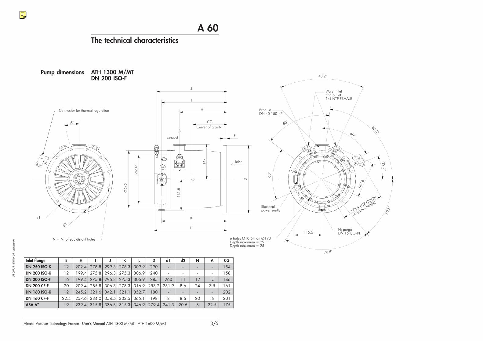
ATH 1300 M/MTDN 200 ISO-F
Inlet flangeDN 250 ISO-KDN 200 ISO-KDN 200 ISO-FDN 200 CF-FDN 160 ISO-KDN 160 CF-FASA 6”
E1212162012
22.419
H202.4199.4199.4209.4245.2257.6239.4
I278.8275.8275.8285.8321.6334.0315.8
J299.3296.3296.3306.3342.1354.5336.3
K278.3275.3275.3278.3321.1333.5315.3
L309.9306.9306.9316.9352.7365.1346.9
D290240285
253.2180198
279.4
d1--
260231.9
-181
241.3
d2--
118.6
-8.620.6
N--
1224-
208
CG154158146161202201175
A--
157.5
-18
22.5
Pump dimensions

A 60
Alcatel Vacuum Technology France - User’s Manual ATH 1300 M/MT - ATH 1600 M/MT
The technical characteristics
GB
0072
8 -
Editi
on 0
8 -
Janu
ary
04
Pump dimensions
4/5
ATH 1600 M/MTDN 200 ISO-F
Inlet flangeUVG 250DN 250 ISO-FDN 250 ISO-KDN 250 CF-FDN 200 ISO-FDN 200 ISO-KDN 200 CF-FASA 6”
E1616122616122019
H199.4199.4199.4210,9199.4199.4225.9239.4
I285.8285.8285.8297,3285.8285.8312.3325.8
J306.3306.3306.3317,8306.3306.3332.8346.3
K285.3285.3285.3285.3285.3311.8325.3
L317.4317.4317.4296,8317.4317.4343.9357.4
D350335290306285240
253.2279.4
d1320310
-284260
-231.9241.3
d21511-
8,611-
8.620.6
N1212-
3212-
248
CG139141154152161176175150
A15°15°
-5,625°
15°-
7.5°22.5°

A 60The technical characteristics
GB
0072
8 -
Editi
on 0
8 -
Janu
ary
04
Alcatel Vacuum Technology France - User’s Manual ATH 1300 M/MT - ATH 1600 M/MT 5/5
Out.1/8 NPT female
For 1/4" ext. diam. tube
For 1/4" ext. diam. tube
DN 16 ISO-KF
In. 1/8 NPT female
66
30
14
29
25.25
55 62.5
28 68.5
66
74.9
28.9
50.550.5
3.93.9
12.325
Water valvedimensions
Air inlet valvedimensions

1/1
GB
0072
9 -
Editi
on 0
1 -
Janu
ary
01
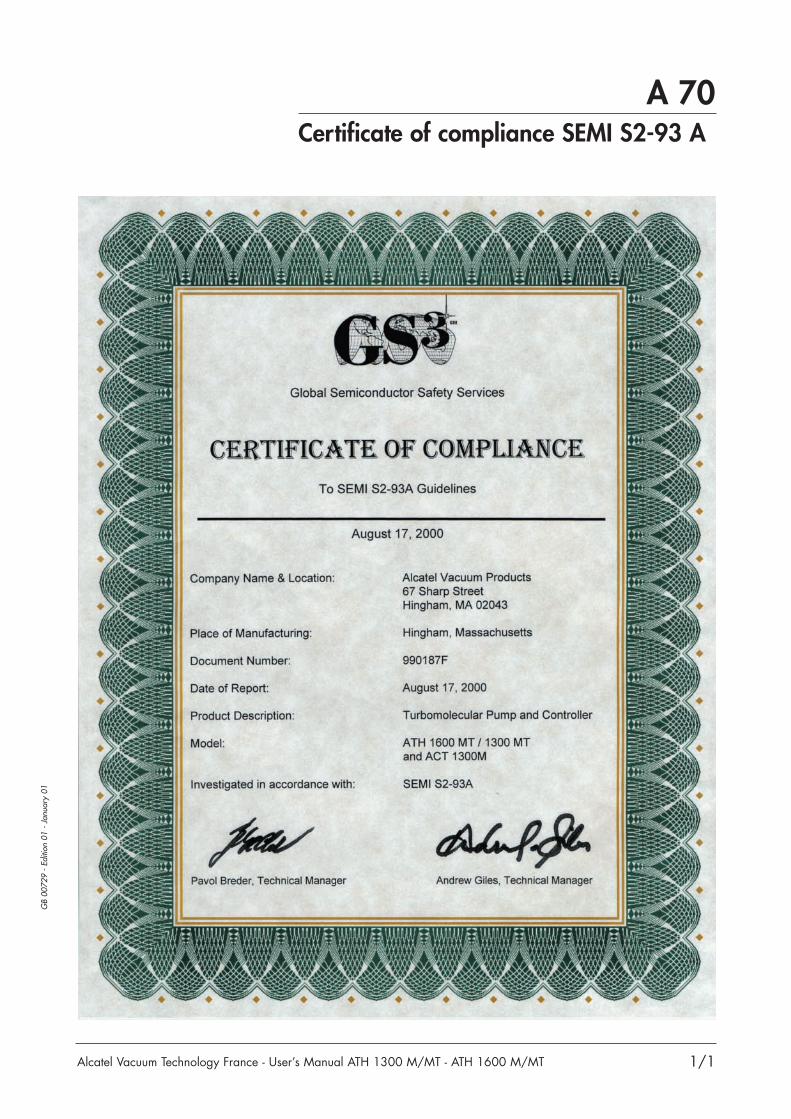
A 70
Alcatel Vacuum Technology France - User’s Manual ATH 1300 M/MT - ATH 1600 M/MT
Certificate of compliance SEMI S2-93 A


B 10Safety instructions
1/5
GB
0073
1 -
Editi
on 0
5 -
Nov
embe
r 02
Alcatel Vacuum Technology France - User’s Manual ATH 1300 M/MT - ATH 1600 M/MT
Before switching on the pump, the user shouldstudy the manual and follow the safety instructions listedin the compliance certificate booklet supplied with thepump.
• The controllers must be connected to an electricalinstallation including an ground connection in compliancewith decree 88.1056 of 14th November 1988.
• Our products are designed to comply with current EECregulations. Any modification of the product madeby the user is liable to lead to non-compliance withthe regulations, or even to put into doubt the EMC(electromagnetic compatibility) performance and the safetyof the product. ALCATEL declines any responsibility forsuch operations.
CAUTION!
This pump is not equipped with an emergencystop EMO device because it is designed for use on processtools and integration with the process tool EMO.
CAUTION!
This pump is not equipped with a lock out/tagout (LO/TO) device because it is designed for use on pro-cess tools.In order to properly secure the pump for installation or/and maintenance, the entire tool needs tobe properly locked-out/tagged out in accordance withOSHA requirement 29 CFR.1910.147.
CAUTION!
Risk of electrical shock. Switch off the pump andwait before disconnecting the main cable, aslong as the rotor is moving. Only the authorizedand trained technicians can perform intervention
on the equipment.
WARNING
B 10Safety instructions
2/5
GB
0073
1 -
Editi
on 0
5 -
Nov
embe
r 02
Alcatel Vacuum Technology France - User’s Manual ATH 1300 M/MT - ATH 1600 M/MT
• The EMC performance of the product is obtained onthe condition that the installation complies with EMC rules.In particular, in disturbed environments, it is essential to: - use shielded cables and connections for interfaces,- stabilize the power supply line with shielding fromthe power supply source to a distance of 3 m fromthe product inlet.
• Magnetic field level: the level for the static fieldsmeasured at the exterior of the pump is a maximum of0.2 mT.
• The units containing control circuits are designed toguarantee normal safety conditions taking their normaloperating environment into account (use in rack).In specific cases of use on tables, make sure that noobjects enter the ventilation openings or block the openingswhen handling the units.
When switching off an item of equipmentcontaining loaded capacitors at over 60 VDC or25 VAC, take precautions concerning the accessto the connector pins (single-phase motors,
equipment with line filter, frequency converter, monitoringunit, etc.). Wait 1 minute after pump switch off beforeoperating on the product.
WARNING
When handling the equipment, usethe devices provided for thispurpose (hoisting rings, handle, etc.).
WARNING
Can cause muscle strain or back injury.Use lifting aids and proper liftingtechniques when removing or replacing.
HEAVY OBJET
Risk of tilting over: although compliance withEEC safety regulations is guaranteed (normalrange ± 10°), it is recommended to takeprecautions against the risk of tilting over
during handling, installation and operation (refer to A 60for the location of the center of gravity) for pump andcontroller.
WARNING

B 10Safety instructions
3/5
GB
0073
1 -
Editi
on 0
5 -
Nov
embe
r 02
Alcatel Vacuum Technology France - User’s Manual ATH 1300 M/MT - ATH 1600 M/MT
The vacuum pump is also a compressor:incorrect use may be dangerous.Study the user manual before starting up thepump. External inputs (contact or voltage) can
be used to stop the turbomolecular pump in case ofroughing pump power failure (see External fault on B 91).
WARNING
The access to the rotor of a turbomolecularpump with an unconnected intake is dangerous.Similarly, if the pump is not switched on, it maybe driven by another pump in operation (risk of
injury).
WARNING
• Make sure that the parts or chambers connected tothe inlet of our pumps withstand a negative pressureof 1 bar in relation to the atmospheric pressure.
• The leaktightness of the products is guaranteed whenthey leave the factory for normal operating conditions.It is the user's responsibility to maintain the level ofleaktightness particularly when pumping dangerous gases.
For process pumps:If loss of purge flow creates a significant risk,then the external monitoring of the purge flowand the response to loss of purge flow must be
provided by the process equipment and interlocked ifnecessary.If pyrophoric materials above the LEL are sent to thepump then nitrogen should be supplied at a rate toensure that concentration is diluted to be below the LEL,in addition an interlock should be provided to ensure thatgas flow to the pump is stopped when nitrogen is lost.
WARNING
• The performance and the operational safety of thisproduct are guaranteed provided that it is used in normaloperating conditions.

B 10Safety instructions
4/5
GB
0073
1 -
Editi
on 0
5 -
Nov
embe
r 02
Alcatel Vacuum Technology France - User’s Manual ATH 1300 M/MT - ATH 1600 M/MT
Safety interlock.The pump motor is protected against overloadthrough the drive "start/stop" and enablecontrol circuitry of the variable speed controller.
The drive start/stop includes solid state components. Ifhazards due to accidental contact with moving machineryor unintentional flow or liquid, gas or solids exist, anadditional hardwired stop circuit is required to removeAC input power to the drive.It is never required to override this interlock duringinstallation, use or maintenance.Once activated power will be switch off and the pumpwill be put in a safe condition. When a fault occurs, thecause must be corrected before the fault can be cleared.It is required to switch power off and on to clear thefault.
WARNING
The machines are designed so asto prevent any thermal risk to theuser's safety. However, specific
operating conditions may generate, temperaturesjustifying particular attention on the part of the user(external surfaces > 70°C on exhaust connections).Always use gloves before servicing.
WARNING
Contact may cause burn.Do not touch or wear protective gearbefore servicing.
HOT SURFACE
If any pyrophoric, toxic, oxider or flammablematerial can be sent to the pump, then anexhaust monitor should be used in thesecondary exhaust to ensure that gas flow to
the pump is stopped when secondary exhaust is lost.Also, if flammable materials are sent to the pump, thecustomer will need to provide a hardware based LELdetection in the secondary exhaust (capable of detectingat 25% of the LEL) that will stop chemical supply to thepump when gas is detected at 25% of LEL for thatflammable material.
WARNING

B 10Safety instructions
5/5
GB
0073
1 -
Editi
on 0
5 -
Nov
embe
r 02
Alcatel Vacuum Technology France - User’s Manual ATH 1300 M/MT - ATH 1600 M/MT
Located on the pump housing, thislabel warns the user againstpossible risk of injury due to any
hand contacts with hot surface. It demands to useprotective gloves before any intervention is performed.
WARNING
Contact may cause burn.Do not touch or wear protective gearbefore servicing.
HOT SURFACE
Located on the pump housing, thislabel indicates that due to its heavyweight, the product should not be
handled manually, but always through appropriatehandling devices.
WARNING
Can cause muscle strain or back injury.Use lifting aids and proper liftingtechniques when removing or replacing.
HEAVY OBJET
Located on the pump housing, thislabel indicates that some of theinternal parts are energized and
could cause electrical shocks in case of contact. It advicesto disconnect the pump before any intervention or toproperly lock-out and tag-out the equipment breakerbefore any intervention on the pump.
WARNINGHAZARDOUS VOLTAGE ENCLOSEDDanger risk of electric shock, disconnect mainpower source and heater power. (if heater is used, max 110/230 V, 300 VA, 50/60 Hz).Prior to servicing and wait 5 minutes beforeworking on this equipment.
Located on thepump housing, thislabel warns the
user against pumped process gas that could be dangerousand toxic and could cause severe injuries or death. Itprecises that any preventive maintenance operation canonly be performed by trained personnel.
WARNINGFLAMMABLE, CORROSIVE AND TOXICCHEMICALS LOCATED WHITHIN THE ENCLOSUREExplosure may result in severe injuryor death.Preventive maintenance must be doneby trained personnel only.
Pump connection to the installation :It is strongly recommended to secure the maglevturbopump installation to prevent any safetyhazard to the user in standard operating
conditions. Refer to B30.
WARNING


B 20Unpacking and storage
GB
0073
2 -
Editi
on 0
6 -
Janu
ary
04
Alcatel Vacuum Technology France - User’s Manual ATH 1300 M/MT - ATH 1600 M/MT 1/2
Unpacking
To keep your product in the clean condition in which it leftour factory, we recommend to unpack the pump only onits assembly site.
Risk of tilting: compliance with the EEC safetyrules is guaranteed (normal range ± 10°). Still, itis recommended to take precautions in regard tothe risk of tilting during product handling, instal-
lation and operation (refer to A60 for the location of thecenter of gravity for pump and controller).
WARNING
Unpack the equipment carefully and keep the packaging. Make sure that the equipment has not beendamaged during the transport. If it has been damaged,take the necessary steps with the carrier and informAlcatel if necessary.In all cases, we recommend that you keep the packaging(reprocessing material) to transport the equipment ifnecessary or for prolonged storage.
CAUTION!
Electricalcable
Thermostaticcable
Water valve
Turbomolecularpump
Controller

B 20Unpacking and storage
2/2
GB
0073
2 -
Editi
on 0
6 -
Janu
ary
04
Alcatel Vacuum Technology France - User’s Manual ATH 1300 M/MT - ATH 1600 M/MT
This packaging also contains other cardboard boxes,for the accessories (screen filter, air inlet valve, watervalve, purge device and high temperature sticker) and forthe electric cable.
It is packaged in a separated cardboard box.Lift the device out of its packaging (weight 8.5 kg) by hand.
It is packaged in a separated cardboard box.
Lift the pump out of its packagingby using the hoisting rings locatedon the inlet blanking flange (weight
ATH 1300 M: 34 kg; ATH 1600 M: 35.5 kg.
Controller storage
The accessories
The controller
The pump
Connection forair inlet valve
and nitrogen device
Inlet
Exhaust
Pump storage
WARNING
Can cause muscle strain or back injury.Use lifting aids and proper liftingtechniques when removing or replacing.
HEAVY OBJET
ASA 6’’, ISO or CF-Fflange blanking.
Blanked witha DN 40 ISO-KF protector.
Blanked witha DN 16 ISO-KF protector.
The controller can be stored in its cardboard boxat storage temperature between - 20°C and + 70°C.CAUTION!
If you need to store a pump which has run,don't forget to blow out the water line and purge the functional block with N2.
CAUTION!
If the pump is going to be put into storage, theinlet and exhaust connections should be blanked off. Thisequipment can be stored without any precautions at anambient temperature between 5 and 40°C.
CAUTION!

B 30Pump connections to an installation
1/6
GB
0073
3 -
Editi
on 1
0 -
Febr
uary
03
Alcatel Vacuum Technology France - User’s Manual ATH 1300 M/MT - ATH 1600 M/MT
Maglev pump connectioninstructions
Why securing MAGLEV pump
installation ?
Maglev hybrid Turbopumps are designed so as to preventany safety hazard to the user in standard operatingconditions.However, some operating conditions may generate hazardsfor the user and the environment : the kinetic energy storedin a maglev turbopump is very high. In case of a mechani-cal failure an improperly installed pump could be ejectedfrom the equipment if the kinetic energy was transferred tothe pump body. It is absolutely necessary to install the pump according tothe following installation specifications to secure the userand the equipment.
Alcatel declines any responsibility if the pump installationis not designed in accordance with these installationspecifications.
ATHM
1
32
Installations specificationsChamber
Equipment
Frame
Maglev pump connection instructions
Respect the item 1, 2 and 3 pump connection instructions.

B 30
Alcatel Vacuum Technology France - User’s Manual ATH 1300 M/MT - ATH 1600 M/MT
Pump connections to an installation
2/6
GB
0073
3 -
Editi
on 1
0 -
Febr
uary
03
Worst Case Turbo PumpCrash Scenario
Definitions
The kinetic energy of the rotor has to be absorbed by theinstallation if the pump seizes suddenly.The maximum resulting loads have been measured on atest bench by simulating a worst case Turbo pump crashwith a rotor split into 2 parts at nominal speed. Theimpact of the rotor parts creates the following transientloads.The rotor parts can be ejected out of the pump inletflange and can impact on the plate of the valve or anyother part of the system. If this is placed close to the turbopump and if it has high stiffness the impact can create ahigh axial load on the system. Such axial force has notbeen observed on a standard pendulum valve.The impact of the rotor parts on the housing will create aradial force on the housing. This radial force will create abending moment on the system as a function of thedistance to the pump.The deceleration of the rotor parts creates a torque valueon the pump housing, which is transmitted to the system.
The maximum values of the axial force and the bendingmoment occur at approximately the same time. A delay ofup to several ms has been observed for the maximumtorque value.
Axial loads (a)
Bending moment (b)
Torque (c)
Loads transmitted to thesystem (item 1)
Pump
Rotor
Pump fixed tosystem : valve
Pendulum plate
Front view
Pump
Top view
Torque (c)
Loads :
Bendingmoment (b)
Axial load (a)

Alcatel Vacuum Technology France - User’s Manual ATH 1300 M/MT - ATH 1600 M/MT
B 30Pump connections to an installation
3/6
GB
0073
3 -
Editi
on 1
0 -
Febr
uary
03
Loads transmitted to thesystem (cont.)
ATH 1300 MTransmitted forces on Alcatel test bench
Torq
ue -
Ben
ding
mom
ent -
K N
.m
Axi
al fo
rce
- K
N
TorqueBending momentAxial force
Time - ms
Pump model Unit ATH 1300 ATH 1600Nominal speed (rpm) 34000 39000Energy kNm 60 76Torque Max. KNm 23 30
Duration ms 1.3 2.5Delay ms 1.5 2.1
Bending moment Max. KNm 17 21Duration ms 0.7 1.3Delay ms 0 0
Axial force* Max. KN 0<<316 0<<398Duration ms 0.4 0.8Delay ms 0 0
* Max. axial force occurs if the pump inlet is obstructed with high stiffness parts.There is no load if the system has low stiffness (i.e. valve).
ATH 1600 MTransmitted forces on Alcatel test bench
Torq
ue -
Ben
ding
mom
ent -
K N
.m
Axi
al fo
rce
- K
N
TorqueBending momentAxial force
Time - ms

Inlet flange installationconditions (item 2)
B 30Pump connections to an installation
Alcatel Vacuum Technology France - User’s Manual ATH 1300 M/MT - ATH 1600 M/MT 4/6
GB
0073
3 -
Editi
on 1
0 -
Febr
uary
03
We strongly recommend the use of ISO-F or CF-F flanges.ISO-K type flanges are not recommended to fastenturbomolecular because:• There is no visual reminder (like threaded holes on ISO-F)
to signal how many clamps are needed to secure the pump,• It is not as easy to fasten claw clamps on ISO-K flanges as
to secure bolts on ISO-F flanges,• The ISO-K flanges do not prevent accidental rotation of the
pump on the equipment flange in case of pump rotor crash.This rotation could damage the foreline and the purge gasline which would generate hazards for the user.
WARNING
For safety reasons, it is important to tighten the bolts with atorque wrench according to the specified values :- lower torque risk of loosened bolts- higher torque risk of damaging the bolts.
WARNING
The resulting maximum loads from a crash have to be takeninto account by the pump assembling bolts.Design and secure the pump frame so that it can withstandthe loads.According to the housing type:
Mounting holes ATH 1300 - ATH 1600
at inlet flanges
Inlet flange DN200 ISO-F DN250 ISO-F DN200 CFF DN250 CFF
Type of bolts dictated M 10 M 10 M 8 M 8
Number of bolts dictated 12 12 24 32
Bolt metric grade 12-9 12-9 12-9 12-9
Installation torque per 30 30 20 20
bolt (N.m)
Total clamping force (N) 161500 161500 266000 355000
Alcatel Vacuum Technology France - User’s Manual ATH 1300 M/MT - ATH 1600 M/MT
B 30Pump connections to an installation
5/6
GB
0073
3 -
Editi
on 1
0 -
Febr
uary
03
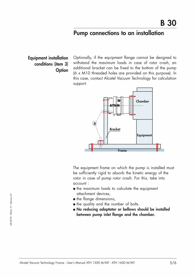
The equipment frame on which the pump is installed mustbe sufficiently rigid to absorb the kinetic energy of therotor in case of pump rotor crash. For this, take intoaccount : the maximum loads to calculate the equipment
attachment devices, the flange dimensions, the quality and the number of bolts. No reducing adaptator or bellows should be installed
between pump inlet flange and the chamber.
Equipment installationconditions (item 3)
Option
Optionally, if the equipment flange cannot be designed towithstand the maximum loads in case of rotor crash, anadditional bracket can be fixed to the bottom of the pump(6 x M10 threaded holes are provided on this purpose). Inthis case, contact Alcatel Vacuum Technology for calculationsupport.
ATHM
3
Chamber
Equipment
Bracket
Frame

B 30
Alcatel Vacuum Technology France - User’s Manual ATH 1300 M/MT - ATH 1600 M/MT
Pump connections to an installation
6/6
GB
0073
3 -
Editi
on 1
0 -
Febr
uary
03
The pump can operatein any position
In.
In.
In.
In.
B 31Inlet and exhaust connections
1/3
GB
0232
9 -
Editi
on 0
1 -
Janu
ary
04
Alcatel Vacuum Technology France - User’s Manual ATH 1300 M/MT - ATH 1600 M/MT
Vacuum connections
At inlet:
Screen filter
Mounting of the insertable inlet flange
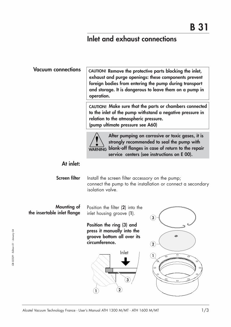
Install the screen filter accessory on the pump; connect the pump to the installation or connect a secondaryisolation valve.
Position the filter (2) into theinlet housing groove (1).
Position the ring (3) andpress it manually into thegroove bottom all over itscircumference.
Remove the protective parts blocking the inlet,exhaust and purge openings: these components preventforeign bodies from entering the pump during transportand storage. It is dangerous to leave them on a pump inoperation.
After pumping on corrosive or toxic gases, it isstrongly recommended to seal the pump withblank-off flanges in case of return to the repairservice centers (see instructions on E 00).
1
2
3
Inlet
21
3
CAUTION!
Make sure that the parts or chambers connectedto the inlet of the pump withstand a negative pressure inrelation to the atmospheric pressure.(pump ultimate pressure see A60)
CAUTION!
WARNING
B 31Inlet and exhaust connections
2/3
GB
0232
9 -
Editi
on 0
1 -
Janu
ary
04
Alcatel Vacuum Technology France - User’s Manual ATH 1300 M/MT - ATH 1600 M/MT
Secondary isolation valve
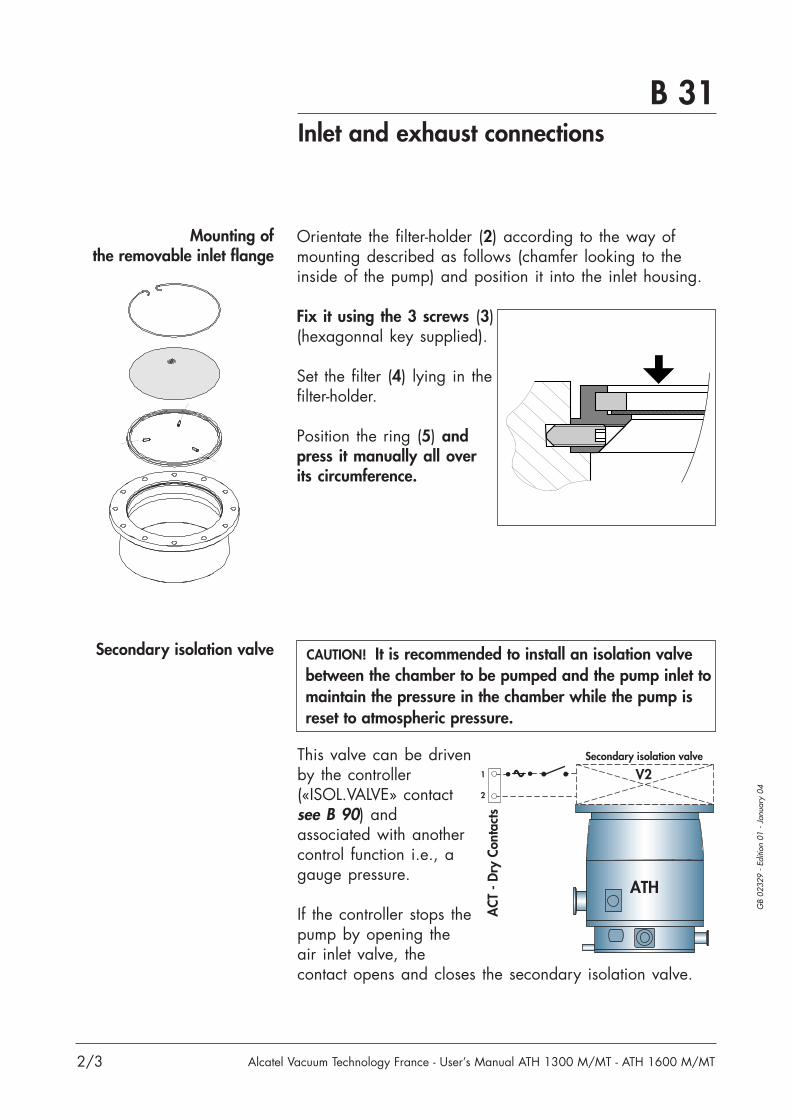
This valve can be drivenby the controller(«ISOL.VALVE» contactsee B 90) andassociated with anothercontrol function i.e., agauge pressure.
If the controller stops thepump by opening theair inlet valve, thecontact opens and closes the secondary isolation valve.
ACT
- D
ry C
onta
cts
1
2
Secondary isolation valve
ATH
V2
It is recommended to install an isolation valvebetween the chamber to be pumped and the pump inlet tomaintain the pressure in the chamber while the pump isreset to atmospheric pressure.
CAUTION!
Mounting of the removable inlet flange
Orientate the filter-holder (2) according to the way ofmounting described as follows (chamfer looking to theinside of the pump) and position it into the inlet housing.
Fix it using the 3 screws (3)(hexagonnal key supplied).
Set the filter (4) lying in thefilter-holder.
Position the ring (5) andpress it manually all overits circumference.
B 31Inlet and exhaust connections
3/3
GB
0232
9 -
Editi
on 0
1 -
Janu
ary
04
Alcatel Vacuum Technology France - User’s Manual ATH 1300 M/MT - ATH 1600 M/MT
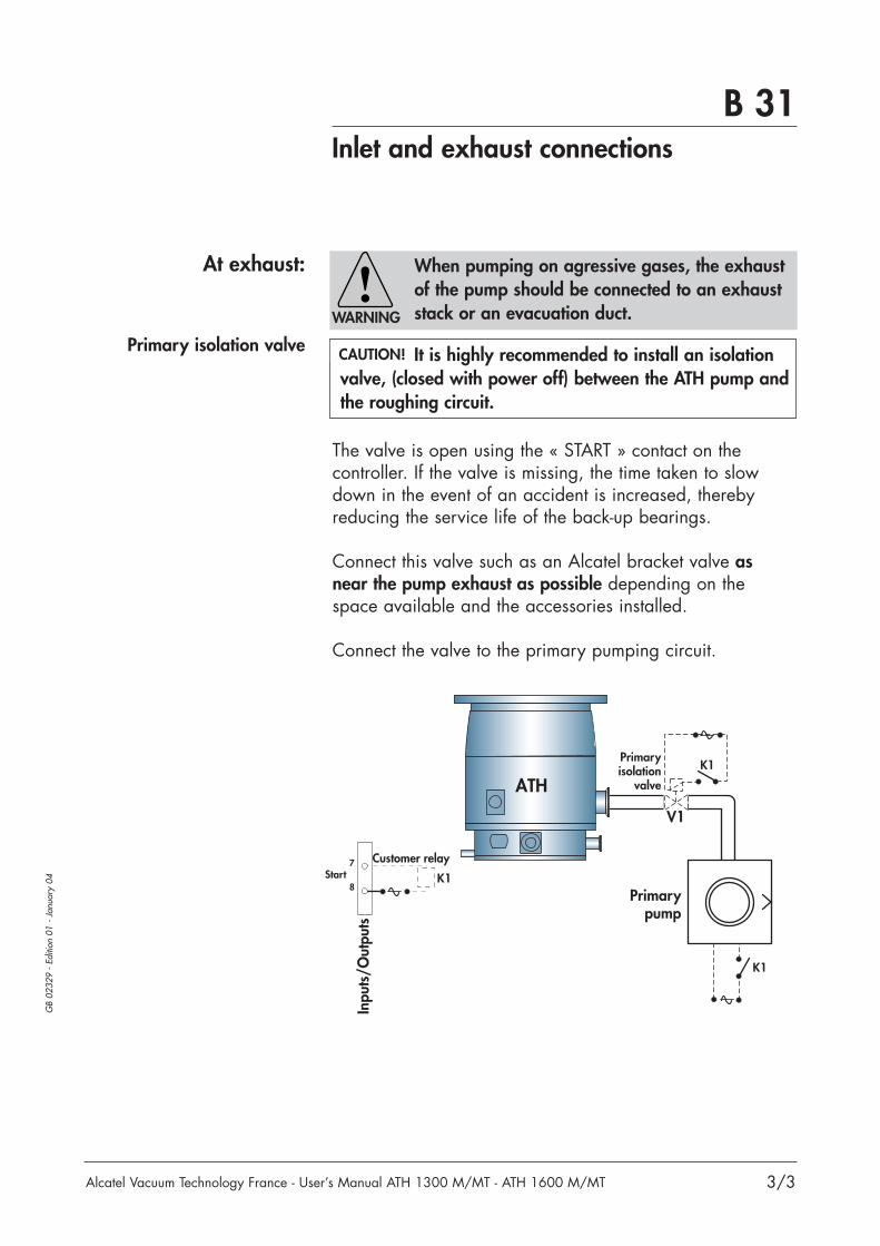
At exhaust:
Primary isolation valve
The valve is open using the « START » contact on thecontroller. If the valve is missing, the time taken to slowdown in the event of an accident is increased, therebyreducing the service life of the back-up bearings.
Connect this valve such as an Alcatel bracket valve asnear the pump exhaust as possible depending on thespace available and the accessories installed.
Connect the valve to the primary pumping circuit.
Inpu
ts/O
utpu
ts
7
8Start
Customer relay
K1
V1
Primaryisolation
valve
K1
ATH
Primarypump
K1
When pumping on agressive gases, the exhaustof the pump should be connected to an exhauststack or an evacuation duct.
It is highly recommended to install an isolationvalve, (closed with power off) between the ATH pump andthe roughing circuit.
CAUTION!
WARNING


B 40
Alcatel Vacuum Technology France - User’s Manual ATH 1300 M/MT - ATH 1600 M/MT
Air inlet valve connection(option)
1/2
GB
0073
4 -
Editi
on 0
7 -
Mar
ch 0
3
Function
Vacuum connection
Without purge device
With purge device
The air inlet valve is calibrated to reset the volume of the pump to atmospheric pressure. When the pump is isolated (at inlet and exhaust) the rotorslow down efficiency is increased.If the venting time is setted, the reset to atmosphericpressure takes place when the pump is stopped or whenfaults are registered on the controller (see C 50).
Air inlet valve is delivered with a DN 16 long nipple notused in this installation.Install the valve on the DN 16 fitting of the pump.The valve must be connected to an inert gas line whichcan be for example dry nitrogen (Pressure between 1 and1.5 bars absolute) (see B 50 for nitrogen characteristics).Connect the inert gas line with a rigid stainless stell orflexible pipe (ext. diam 1/4“).
See B 50 .
Blank-off frange
Inert gas

B 40
Alcatel Vacuum Technology France - User’s Manual ATH 1300 M/MT - ATH 1600 M/MT
Air inlet valve connection(option)
2/2
GB
0073
4 -
Editi
on 0
7 -
Mar
ch 0
3
Electrical connection
ATH
N2V3
Air inletvalve
8
7Air valve 12 VDC
Connect the valve (12 VDC)powered and driven by the controller via the «AIR VALVE» contact onthe Dry Contact connector(see B 90).
Protective earthing instruction
The grounding wire of the air inlet cable has to be fixed tothe grounding fixation on the ACT rear panel.
ATH
N2V3
Air inletvalve
10
9Air inlet
It is also possible toconnect another valve on the «AIR INLET» contact onthe Dry Contact connectorbut, in this case, you mustuse an external powersupply.
For this:- use a NC (Normally Closed) valve,- use an external power supply,- connect the air inlet valve between “9-10“ contacts,- adjust the inert gas pressure to 1.1/1.5 bar
(absolute pressure).
See C 30 to configure the menus “Time to venting“ and“Venting time“ parameters.
DRY CONTACTS
PUMP CABLE
REM.
RS 232MODEM
RS 232
Air Inlet valve grounding cable
Air Inlet valve cable

B 50Nitrogen purge device connection
1/3
GB
0073
5 -
Editi
on 0
7 -
Mar
ch 0
3
Alcatel Vacuum Technology France - User’s Manual ATH 1300 M/MT - ATH 1600 M/MT
Characteristics of filtered
dry nitrogen supply
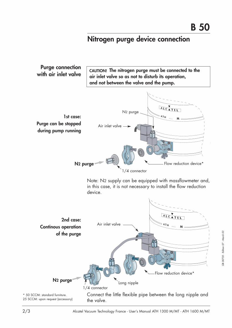
Purge connectionwithout air inlet valve
A filtered dry nitrogen supply with the followingcharacteristics is required:- Dew point < 22°C- Dust < 1 µm- Oil < 0.1 ppm- Absolute pressure of 1 to 1.5 bar.
The nitrogen purge must be connected directly tothe pump exhaust port.
Connect the nitrogen supply to the DN 16 purge fitting*.The nitrogen flow reduction device controls the pressureand guarantees a flow rate of 50 SCCM at pressure1.1 bars.
Note: N2 supply can be equipped with a massflowmeter,and in this case, it is not necesssary to install the flowreduction device.
* Different connection accessories can be found in the ALCATEL catalog.
1/4 connector
Flow reduction device
N2 purge
CAUTION!
B 50Nitrogen purge device connection
2/3
GB
0073
5 -
Editi
on 0
7 -
Mar
ch 0
3
Alcatel Vacuum Technology France - User’s Manual ATH 1300 M/MT - ATH 1600 M/MT
2nd case:Continous operation
of the purge
Connect the little flexible pipe between the long nipple andthe valve.
* 50 SCCM: standard furniture.25 SCCM: upon request (accessory)
Long nipple
Flow reduction device*
Air inlet valve
1st case:Purge can be stoppedduring pump running
1/4 connector
1/4 connector
Flow reduction device*
Air inlet valve
Purge connectionwith air inlet valve
The nitrogen purge must be connected to theair inlet valve so as not to disturb its operation,and not between the valve and the pump.
N2 purge
N2 purge
N2 purge
Note: N2 supply can be equipped with massflowmeter and,in this case, it is not necessary to install the flow reductiondevice.
CAUTION!

B 50Nitrogen purge device connection
3/3
GB
0073
5 -
Editi
on 0
7 -
Mar
ch 0
3
Alcatel Vacuum Technology France - User’s Manual ATH 1300 M/MT - ATH 1600 M/MT
Adjust the flow rate
20
1.0 1.1 1.2 1.3 1.4 1.5
70
60
50
40
30
Flow rate (SCCM)
Purge 50 SCCM
Purge 25 SCCM
Absolute pressure at inlet (bar)
Feed the nitrogen purgethroughout pumpingaccording to the flow rateand pressure values inthe scale given.
To limit the flow rateat 25 SCCM, connectthe nitrogen flow reductiondevice accessory(see A 50).
When the neutral gas purge is stopped, the pum-ped process gases can passed from fore vacuum side tothe high vacuum side, and condensate, eventually, dama-ge internal maglev bearings.We provide to monitor purge flow to warranty a perma-nent gas flushing for maglev back-up bearing protection.
CAUTION!


1/2
GB
0073
6 -
Editi
on 1
0 -
Janu
ary
04
Alcatel Vacuum Technology France - User’s Manual ATH 1300 M/MT - ATH 1600 M/MT
B 60Water cooling connection
Characteristicsof water cooling
For ATH 1300 Mand ATH 1600 M
model
For ATH 1300 MTand ATH 1600 MT
model
- Provide a water inlet pipe and a tap to adjustthe flow rate.- Connect the water valveto the water inlet line usinga flexible tube following theassembly diagram (see A 60):- Connect the other nippleto the draining circuit.
Waterinlet
Wateroutlet
Avoid to screw the connector on the valve inletport using a 13 mm flat wrench, to maintain it(water leak risk).
CAUTION
In order to limit the corrosion and clogging of the coolingpipes, it is recommended to use cooling water with thefollowing characteristics:- treated soft water or non-corrosive industrial water- pH between 7.5 and 11- hardness < 7 milli-equivalent/dm3
- Resistivity > 1500 Ω.cm- Solid pollution < 100 mg/dm3
- Solid particle size (maxi): 0.03 mm2
- Pressure range between 2 and 7 bars- Temperature: 15 < T < 25°C- Flow rate: 60 l/h- Deionized water compatible
- Provide a water inlet pipe and a tap to adjust the flow rate.- Connect the water inletline to one of the coolerwater fittings 1/4 NPT female on the pump, with the otherfitting connected to the water draining circuit via a tube(supplied by customer).

2/2
GB
0073
6 -
Editi
on 1
0 -
Janu
ary
04
Alcatel Vacuum Technology France - User’s Manual ATH 1300 M/MT - ATH 1600 M/MT
B 60Water cooling connection
Electrical connection
Connect the water valve via the «WATER VALVE» contacton the DRY CONTACTS connector.The temperature is regulated by a sensor integrated intothe pump (see B 70).
Temperature is regulated by the controller.
Protective earthing instruction
The grounding wire of the water valve cable has to befixed to the grounding fixation on the ACT rear panel. (see B 70 - 1/3).
6
5
4
3Water valve
Thermostat
Thermostat
Dry
con
tact
s
Watervalve
Heatingband
11
12
Do not mount water fittings above electricalcomponents in case of leak at water fittingconnection.
CAUTION

B 70Heating band connection
1/2
GB
0173
1 -
Editi
on 0
2 -
Janu
ary
04
Alcatel Vacuum Technology France - User’s Manual ATH 1300 M/MT - ATH 1600 M/MT
INPUTS/OUTPUTS
DRY CONTACTS
PUMP CABLE
REM.
RS 232MODEM
RS 232
Don’t forget to connectthe connector to theground. (Screw M5).
Thermostaticcable
Connect to the heatingband on the pump
Connect to the water valve
Connect to the «Dry Contacts» on terminals 5-6 and 11-12,or on the machine if thetemperature is regulate by thecustomer device (see B 90).
Connect the thermostatic cable to the power line (main with ground connection).
Water valve cable
Water valve grounding cable
For thermostated MTmodels
Connection
These pumps are equipped with an heating band,a thermal sensor and a valve to regulate the water flowrate.The body of the pump can be heated to 75°C to avoid gascondensation in the pump on the semiconductor processes.
Connect the thermostatic cable as follows:
Voltage or current hazard sufficientto cause shock. Disconnect and isolate power before servicing.
WARNINGHAZARDOUS VOLTAGE ENCLOSEDDanger risk of electric shock, disconnect mainpower source and heater power. (if heater is used, max 110/230 V, 300 VA, 50/60 Hz).Prior to servicing and wait 5 minutes beforeworking on this equipment.
Ex: model ATH 2300 MT

Hot surfaces are signalled by a label-sticked onhot surfaces. The pump housing temperature canreach 75° C. Contact may cause burn. Do nottouch or wear protective gloves before servicing.
B 70Heating band connection
2/2
GB
0173
1- E
ditio
n 02
- J
anua
ry 0
4
Alcatel Vacuum Technology France - User’s Manual ATH 1300 M/MT - ATH 1600 M/MT
Heating band temperature
The sticker «hot surface» must besticked conspicuously on the pumphousing.
WARNING
Contact may cause burn.Do not touch or wear protective gearbefore servicing.
HOT SURFACE
Temperature is regulated by the controller.
Connect the heater cable via the «THERMOSTAT» contacton the DRY CONTACTS connector and to the power line(110 or 230 VAC).The heater cable (110 or 230 V) (see A 50) must bechoosen in function of the power supply (110 or 230 V).
The temperature can be choosen on the controller(between 31 and 75°C or OFF).By choosing «OFF» temperature, the heating band isswitched off and the pump is cooled permanently.
The temperature of the pump can be read on the displayof the controller (see C 30).
On certain type of pumps, a thermoswitch is integrated and cut the power supply ofthe heater at pump body temperature of T > 100°C.The thermoswitch is manually resetable from the outside ofthe pump.
6
5Thermostat
Thermostat
Dry
con
tact
s
Heatingband
11
12
* External power supply in accordance with the heater band voltage.
**
6
5
Thermostat
Thermoswitch
Heatingband
WARNING

B 80Electrical connection
1/7
GB
0073
8 -
Editi
on 1
0 -
Janu
ary
03
Alcatel Vacuum Technology France - User’s Manual ATH 1300 M/MT - ATH 1600 M/MT
B 80
Make sure that main switch is off during electrical connection. Danger, risk of electricshock: disconnect main power source and heaterpower prior to servicing (if heater is used,
max. 110/230 V, 300 W, 50/60 Hz).
Study the preliminary precautions (See B 10).
WARNING
All the internal electrical connections required foruse the pump are made prior shipment.However, the electrical connection of the mainpower supply may be provided by the process
tool. An out of phase condition is corrected automatically by the controller.
WARNING
An IEC 417#5019 symbol is located on the rearpanel.
WARNING
The pump doesn't have any internal overcurrentprotection, so it is required to power the pumpfrom a facilities supplied main circuit breakerrated 10 A minimum, and which has a minimum
amp. interrupting current of 10 000 AIC.
WARNING
This pump is not equipped with an emergencystop EMO device because it is designated for useon process tools and integration with the processtool EMO.
Check that the pump is correctly connected to the equip-ment emergency stop system.
WARNING
An internal input contact can be used to signal aroughing pump power failure (see B 91).This will stop the turbomolecular pump avoiding overpres-sure risk in the pump.
CAUTION!
WARNING

B 80
2/7
GB
0073
8 -
Editi
on 1
0 -
Janu
ary
03
Alcatel Vacuum Technology France - User’s Manual ATH 1300 M/MT - ATH 1600 M/MT
INPUTS / OUTPUTS
DRY CONTACTS
PUMP CABLE
REM.
RS 232MODEM
RS 232
B 80Electrical connection
Controller installation
Connections
The unit must be installed in an environment ventilatedeither by natural convection or by the movement of forcedair. Cooling is normally performed by an internal fan whichventilates air from the inside to the outside of the unit.
Connect the controller to the power supplyusing the cable supplied. (Main with ground connection).
Connect the controller to the pump using thecable ordered.
Make various connections if dryinputs/outputs are used (see B 91).
Connect the RS232serial link cable to the connector(cable supplied by customer). (see B 110 and B 120).
Delayed fuses (x2) located belowthe controller:16A - T - 250V(see F 10).
Electrical grounding of controllerframe (M5) for EMC accordance.
Connect the RS 485 serial link tothis connector(see B 100).Analog output is available on thisconnector (see B 100).
Connect the connector with2 squares and 2 screws M3.
Some output contacts are avai-lable on terminal DRY CONTACTS (see B 90).
Not used
Secure manuallythe 2 assembling screws.
Make sure that:- the openings on the bottom, top and rear of the unit arenot blocked;- the ambient temperature does not exceed 50°C;- a free space of at least 15 mm is left behind, above and below the unit;- the controller location is at a height between64.5’’ and 11’’ from the floor.
CAUTION!
WARNINGHAZARDOUS VOLTAGE ENCLOSEDDanger risk of electric shock, disconnect mainpower source and heater power. (if heater is used, max 110/230 V, 300 VA, 50/60 Hz).Prior to servicing and wait 5 minutes beforeworking on this equipment.

B 80Electrical connection
3/7
GB
0073
8 -
Editi
on 1
0 -
Janu
ary
03
Alcatel Vacuum Technology France - User’s Manual ATH 1300 M/MT - ATH 1600 M/MT
Connection betweenpump and controller
On the pump connector 1 - On the pump connector, identify the main index on thepump connector.
2 - Then identify the main index on the cable connector.
3 - Insert the connector in accordance to the main indexand then, press the bayonet type connector axially intoplace and rotate the bayonet ring at the same time until itlocks into position (feel the « click »).
If it is difficult to press and rotate, remove the connectorand check the pins on the pump connector (bent pins).
Try again. Press
Rotate
B 80Electrical connection
4/7
GB
0073
8 -
Editi
on 1
0 -
Janu
ary
03
Alcatel Vacuum Technology France - User’s Manual ATH 1300 M/MT - ATH 1600 M/MT
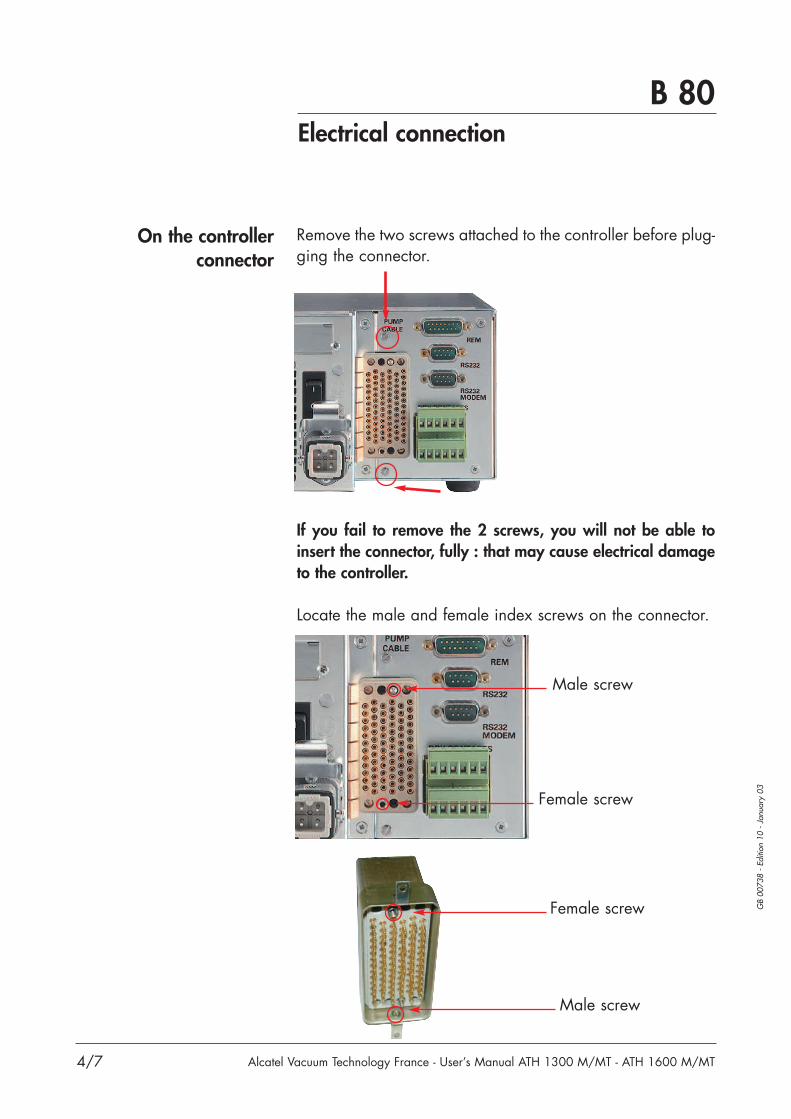
Remove the two screws attached to the controller before plug-ging the connector.
If you fail to remove the 2 screws, you will not be able toinsert the connector, fully : that may cause electrical damageto the controller.
Locate the male and female index screws on the connector.
Male screw
Female screw
Male screw
Female screw
On the controllerconnector

Plug the connector accordingly and press the connectoraxially, tighten manually the 2 screws at the same time (Don’tuse a screwdriver).Caution: if you use a screwdriver, take care to the appliedtorque.There is a risk to break the head screw or the connector.
Assemble the two small screws that you had previously disassembled and check that the surfaces are in contact withthe ACT.
Secure manually the 2 screws. (Don’t used a screwdriver).
Caution: If the two surfacesaren’t in contact, it means thatthe connector is not in well ins-talled, an electrical damagecan occur.
Surface incontact
B 80Electrical connection
5/7
GB
0073
8 -
Editi
on 1
0 -
Janu
ary
03
Alcatel Vacuum Technology France - User’s Manual ATH 1300 M/MT - ATH 1600 M/MT

B 80Electrical connection
6/7
GB
0073
8 -
Editi
on 1
0 -
Janu
ary
03
Alcatel Vacuum Technology France - User’s Manual ATH 1300 M/MT - ATH 1600 M/MT
Main power connectionAt the rear of the
controller
Check that the seal is available on the controller connector.
Identify the main index.
Identify the main index on the female HARTING connector.
Plug the female connector in accordance to the main index,and lock the connector.
Index
Seal
Lock

Alcatel Vacuum Technology France - User’s Manual ATH 2300 M/MT 7/7
B 80Electrical connection
GB
0073
8 -
Editi
on 1
0 -
Janu
ary
03
Typical connection
- A primary isolation valve V1 between the ATH andthe roughing pump;- a secondary isolation valve V2 between the ATH andthe chamber to be pumped;- a relay K1, their contacts drive the valve V1 and theprimary pump power supply;- the thermostatic option.
In this installation, we use:
V1
Primaryisolation
valve
K1
ATH
7
8
6
5
4
3
8
7
2
1Isolation Valve
Water valve= 12 VDC
Air valve= 12 VDC
Thermostat
StartCustomer relay
Dry
con
tact
sIn
puts
/out
puts
Pump cable
Powersupply
K1
ACT
11
12Thermostat
Secondary isolation valve
Watervalve
N2V3
V2
Primarypump
K1
Air inletvalve
Pump cable includes temperature sensor information
Wiring diagram in case of temperature regulation with the controller
Minimum electrical connectionLegendThermostatic cable for ATH MTCustomer supplies recommended by Alcatel


B 90“Dry contacts“ connector wiring
1/1
GB
0073
9 -
Editi
on 0
9 -
Janu
ary
01
Alcatel Vacuum Technology France - User’s Manual ATH 1300 M/MT - ATH 1600 M/MT
Depending on the previous configuration thecontacts are closed (see C 50).
Signaling using outputs
Dry contact outputs250 VAC - 3 A max
Controller outputs12 VDC
Contactfunctionnal status
Their functions are to copythe data concerning thepump operating status.
When the controller detects a bearing operatingfault, it opens the contact.After a stop, it opens when the rotation speedreaches 10000 rpm.This contact can be used to control a secondaryisolation valve which is used to maintain thepressure in the chamber while the pump is resetto atmospheric pressure.
0
1
0
1ISV
Thermos.
Power off Power on Start on Nominal speed Alarm DeStop
Depending on temperature parameter
0
1Watervalve
Depending on temperature parameter
(1)
Isol. valve 1 - 2
The contacts are opened or closed, depending onthe pump temperature and the selected temperature.Thermostat 5 - 6
11-12
Air inlet* 9 - 10
The voltage delivered on this output depends onthe pump temperature and the selectedtemperature.
Water valve 3 - 4
1 2 5 63 4
7 8 11 129 10
12 VDC
12 VDC
The voltage is delivered on this output during the“Venting time” according to the configuration(see C 50).
Air valve* 7 - 8
(1) This function is valid at 10000 rpm + setted delay when Stop or Ext. fault commandsare activated.
* Stop / Ext. fault functions allow to close the contacts at 10000 rpm + setted delay.
When the units containing the control circuitsare equipped with dry contacts outputs, it is thecustomer’s responsability to use the outputs incompliance with safety regulations.
CAUTION!
WARNINGHAZARDOUS VOLTAGE ENCLOSEDDanger risk of electric shock, disconnect mainpower source and heater power. (if heater is used, max 110/230 V, 300 VA, 50/60 Hz).Prior to servicing and wait 5 minutes beforeworking on this equipment.


B 91“Inputs/Outputs“ connector wiring
1/3
GB
0074
0 -
Editi
on 0
9 -
Janu
ary
04
Alcatel Vacuum Technology France - User’s Manual ATH 1300 M/MT - ATH 1600 M/MT
15 1
30 16171819
44 3142 40 39 38 37 36 35 34 33 32
- +~=5 to 30 V
Wiring supplied by customer
fig 1
- +~=
-+~= -+
~=
- +~=
In the case of alocal mode operation of thecontroller, the pump will runonly if the terminal plug(delivered with the controller)is connected on the“Inputs/Outputs” connector.
The control by voltage
The control by drycontacts with
“input control” mode
The” inputs/outputs” connector is located at the rear of thecontroller (DB 44 contacts, female connector).The inputs are considered to be activated if the AC or DCvoltage applied is between 5 and 30 Volts (fig 1).
15 1
30 28 27 25 24 161718
44 41 38 37 36 35 34 32
Wiring suppliedby customer
fig 2Start
Mode input control
Stand-by
Inhibit
Ex. fault
Stop
394042 31
These inputs can be controlled by customer equipmentexternal contacts (fig 2).
It is necessary to read the following table for more information.
15 1
30 18
44 3142 40 39 32
Terminal plug type DB 44contacts male connector
Factory wiring(Soldered-side view)
When the units containing the control circuitsare equipped with dry contacts outputs, it is thecustomer’s responsability to use the outputs incompliance with safety regulations.
CAUTION!
CAUTION!

B 91“Inputs/Outputs“ connector wiring
2/3
GB
0074
0 -
Editi
on 0
9 -
Janu
ary
04
Alcatel Vacuum Technology France - User’s Manual ATH 1300 M/MT - ATH 1600 M/MT
(1) “Input control“ mode: by strapping terminals 39-40, all the (+) terminals are supplied with 15 VDC.Connect the (-) terminals to the dry contact and to the ground.
(2) If the equipment has only one output to stop and start the pump it is possible to order “start” and “stop” in same time.
Ground24, 25, 26, 27,28, 29, 41, 42
37(+) 38(-) 38(-)GND
Remotestart(2)
Voltage5V/30VDC/AC
Dry contacts“Input control“
mode(Strap 39-40)(1)
Function
Command mode
17(+) 16(-) 16(-)GND
Remotestop(2)
35(+) 36(-) 36(-)GND
Remotestandby
31(+) 32(-) 32(-)GND
Externalfault
19(+) 18(-) 18(-)GND
Inhibit
INPU
TS
Rem
ote
func
tion
if“R
emot
e“ m
ode
sele
cted
Not
“Re
mot
e“ m
ode
depe
nden
t (s
afet
y)
- “Remote stop - Ext. fault - Inhibit“ inputs must be valid.- The “Remote start“ allows pump starting when an
impulse or a permanent action is applied on thisinput.
When the input is disabled, the motor is stopped byimpulse or by permanent action.Restart the pump as follows:- desable “ Remote start“- valid “Remote stop“- valid again “Remote start“
- When the “Standby“ is validated, the rotation speedcorresponds to the setted speed (see C30).
- When the “Standby“ is disabled, the rotation speedcorresponds to the nominal speed.
- When the “External fault“ input is desabled the motoris stopped. Actions on the start, stop key (or remote)are desactivated.
- Restart the pump by validating the input “Ext. fault“,and activate the “Start“ (key or remote).
- When the “Inhibit“ is disabled, the controller doesn’tsupply the motor and inhibit the progressing function.There is no air inlet, the actions on the start, stop(key and remote) are desactivated.
- When “inhibit“ is valid, the controller powers themotor and restores the previous operating status.
+
_
GND
Input
INPUT CONTROLMode
Sub D 44 Pts Fem. on ACT
+ 15 V
0 V
39
40
+
_
GND
Input
INPUT CONTROLMode
Sub D 44 Pts Fem. on ACT
+ 15 V
0 V
39
40
“Input control“ mode

B 91“Inputs/Outputs“ connector wiring
3/3
GB
0074
0 -
Editi
on 0
9 -
Janu
ary
04
Alcatel Vacuum Technology France - User’s Manual ATH 1300 M/MT - ATH 1600 M/MT
* This threshold can be set between - 3% and - 50%. It can be accessed on the front panel using the “SET UP“ and “RELAY SPEED“ menu.
15 14
TEMP ANDAT SPEEDAT SPEED
13 12 11 10 9 8 7 6 345 2 1
30 16
44 314243 4041 39
ACC START WARNING
BRAKING POWERFAULT
The output dry contacts
The output dry contact functions is to copy the dataconcerning the pump status.
- The POWER contact is closed following the power-up and afterapproximately 20 seconds. In case of power failure, this contactopens at ≈ 10000 rpm
- The WARNING contact is opened when the pump temperaturereaches alert threshold. It remains open when the pump temperatureis greater than the alarm threshold.
- The WARNING contact closed at temperature below the alertthreshold minus 2°C (Hysteresis).
- The BRAKING contact is closed when the pump decelerates to reachzero speed following a STOP, INHIBIT, or EXTERNAL FAULT action.THE BRAKING contact is always open at speeds below 400 rpm.
- The BRAKING contact is opened after a START action.
- The contact is closed when the START control is activated on thecontroller. The contact can be used to control a primary isolationvalve and via a power relaying device, to control the primary pump.
- The ACCELERATING contact is closed when the motor is inacceleration phase with a speed over 400 rpm. It remains closeduntil the setted speed is reached.
- The ACCELERATING contact is open when a STOP, INHIBIT, orEXTERNAL FAULT action is taken into account.
- The FAULT contact is open following the appearance of any fault(external, temperature, frame, motor, etc…).
- The contact is closed if there are no faults.
- The AT SPEED and THERM. TEMP contact is closed when the settedspeed is reached or when the pump is in overspeed mode (in theevent of modification of reference speed), and when the temperatureis greater than the heating temperature minus 3°C (if thermostatictemperature setted “ON“).
- The AT SPEED and THERM. TEMP contact is opened when a STOP,INHIBIT, or EXTERNAL FAULT action is taken into account, or whenthe pump temperature is not reached, or when the speed decreasesunder the threshold “relay speed“ setted*.
- The AT SPEED contact is closed when the setted speed is reached orwhen the pump is in overspeed mode (in the event of modification ofreference speed),
- The AT SPEED contact is opened when a STOP, INHIBIT, orEXTERNAL FAULT action is taken into account, or when the speeddecreases under the threshold “relay speed“ setted*.
Power 1 - 2
Warning 3 - 4temperature
Braking 5 - 6
Start 7 - 8
Accelerating 9 - 10
Fault 11 - 12
At speed 13 - 14andthermostaticTemperature
At speed (only) 15-30
Not
“Re
mot
e“ m
ode
depe
nden
t (s
afet
y)
OU
TPU
T
OutputDry contact
30 VAC RMS/60 VDC-1A
Sub D 44 Pins Fem. on ACT


B 100
Alcatel Vacuum Technology France - User’s Manual ATH 1300 M/MT - 1600 M/MT 1/1
GB
0074
1 -
Editi
on 0
5 -
Janu
ary
03
"Rem." connector wiring
“Rem.“ connector at the rear of the controller
Used to monitor the selected parameter(see ANALOG OUT menus C 30).
1 2 3 4 5
9 10 11 12
6 7 8
1413 15
RS485 V(+)RS485 V(-)
0V
Analog output (0-10V)
Analog.Output 8 - 15
Analog output signal The signal is transmitted between terminal 8 and 15 ofthe remote connector.Four values can be used to plot curves:
Pump rotation speed* 360 rpm (OV) to 60000 rpm (10V)
Pump temperature 0°C (OV) to 100°C (10V)
Controller temperature 0°C (OV) to 100°C (10V)
Current 0mA (OV) to 8700mA (5.8V)
Factory configuration is setted on speed.
0 10
Voltage (V)00
Con
trolle
r tem
pera
ture
(°C
)
Spee
d (rp
m)
Cur
rent
(mA
)
0
Pum
p te
mpe
ratu
re (°
C)
0
100 10060000 rpm 15000
*ATH 1600 39000 rpm (6.5 V)*ATH 1300 34000 rpm (5.66 V)*ATH 2300 31000 rpm (5.16 V)


B 110RS 232 or RS 485 serial link wiring
1/2
GB
0074
2 -
Editi
on 0
5 -
Janv
ier
04
Alcatel Vacuum Technology France - User’s Manual ATH 1300 M/MT - ATH 1600 M/MT
At the first power-up, the user finds the defaultconfiguration. The serial link parameters can be modifiedby accessing the corresponding unit menu (see C 30).
The default configuration of the serial link is as follows:
Type: RS 232 Transmission speed: 9600 bauds Data length: 8 bits Parity: NONE Stop bit: 1
Refer to C 30 to customize the parameters.
RS232 connector wiring:
1 2 3 4 5
GND (Ground)DTR (Data terminal ready)
TD (Transmission data)(Reception data) RD
(Data set ready) DSR
6 7 8 9
Connection examples:
RS232 type serial linkwith a single controller
DB 9 contacts, male connector.
START STOP STATUS STAND BY
ENTERPREVIOUS
ACT 1300 M
FAULT
1
59
61
9
6
5

B 110RS 232 or RS 485 serial link wiring
2/2
GB
0074
2 -
Editi
on 0
5 -
Janv
ier
04
Alcatel Vacuum Technology France - User’s Manual ATH 1300 M/MT - ATH 1600 M/MT
Rem. connector wiring:1 2 3 4 5
9 10 11 12
6 7 8
1413 15
RS485 V(+)RS485 V(-)
Multiple RS485 serial link:several units (up to 999) canbe controlled on a single link.
«Rem.» connector pins 13 and 14 DB 15 contacts, male connector.
RS 485 communication box
End of the line wiring
(A)(B)

B 120Detailed descriptionof RS232 and RS485 commands
1/8
GB
0074
3 -
Editi
on 0
4 -
June
98
Alcatel Vacuum Technology France - User’s Manual ATH 1300 M/MT - ATH 1600 M/MT
(valid from V3.09A version variable drives)
Conventions applicableto the syntax of all
commands:
Status values
Error messages
ADR
Syntax
Result
DEF
Syntax
Result
adr = address, from 000 to 255<CR> Carriage Return (ascii 13)<LF> Line Feed (ascii 10); between square brackets:
this character is not compulsory.
OK : command executed correctly
Err0 : adjustment error (out of bounds)Err1 : command error (syntax)Err2 : parameter error (e.g. non-hexadecimal character)Err3 : context errorErr4 : checksum error
Specifies the address of the device for networking.
#adrADR,aaa<CR>[<LF>]adr = address of the device before the commandaaa = new address of the devicecondition : 000 ≤ aaa ≤ 255
#aaa,OK or Err2
This command is used to allocate a specific number to each of the products making up a network(loop for RS 232 or parallel for RS 485).
Note : it is important to note down the numberallocated to each device.
List the faults
#adrDEF<CR>List the faults separated by the separator character.
#adr,OK if there is no fault.

B 120Detailed descriptionof RS232 and RS485 commands
2/8
GB
0074
3 -
Editi
on 0
4 -
June
98
Alcatel Vacuum Technology France - User’s Manual ATH 1300 M/MT - ATH 1600 M/MT
GET
Syntax
IDN
Syntax
Result
LEV10
Syntax
Result
List the data (data only)
#adrGETAI<CR>[<LF>] : List analog inputs#adrGETLI<CR>[<LF>] : List logical inputs#adrGETLO<CR>[<LF>] : List logical outputs
Identifies the device which is communicating, and itssoftware version
#adrIDN<CR>[<LF>]
#adr,ACT2300M - Vx.zz’
Returns the type of Variable drive Supervisor, the softwareversion (x), the software edition (zz).
Returns the state of the parameters defined by SET
#adrLEV10<CR>[<LF>]
#adr,nnnnn,sssss,00000,0,ccccc,eeeee,ddddd,pppp,qqqq,jj,kk,lll,mmm
Returns current values:nnnnn: nominal speed set point (in rpm)sssss: stand-by speed set point (in rpm)00000: not used0: not usedccccc: pump working time (in hours)eeeee: electronic working time (in hours)ddddd: start delay (max 14459 s, that is 240 mn 59s)pppp: time to venting (max 3599 s, that is 59 mn 59s)qqqq: venting time (max 3599 s, that is 59 mn 59s)jj: speed threshold for relay (3 to 50%)kk: control temperature (30 to 75°C)lll: bearing threshold (0 to 100%)mmm: bearing current value (0 to 100%)

B 120Detailed descriptionof RS232 and RS485 commands
3/8
GB
0074
3 -
Editi
on 0
4 -
June
98
Alcatel Vacuum Technology France - User’s Manual ATH 1300 M/MT - ATH 1600 M/MT
NSP
Syntax
Result
OPT
Syntax
Result
Switches the speed set point to the nominal speed value
#adrNSP<CR>[<LF>]
#adr,OK
The speed set point for the pump is set to its nominal value.
Used to select possible user choices
#adrOPT01,n<CR>[<LF>]choice of parameters on the analog output:
n = 0 : real pump speedn = 1 : pump currentn = 2 : temperature of pump bodyn = 3 : temperature of internal electronics
#adrOPT02,n<CR>[<LF>]choice of temperature unit
n = 0 : degrees Centigraden = 1 : degrees Fahrenheit
#adrOPT11,n<CR>[<LF>]buzzer
n = 0 : withoutn = 1 : with
#adrOPT14,n<CR>[<LF>]remote mode
n = 0 : offn = 1 : on
#adr,OK
The choice of the temperature unit affects the results ofthe DLR and STA strings and the display (if cabinet fitted).
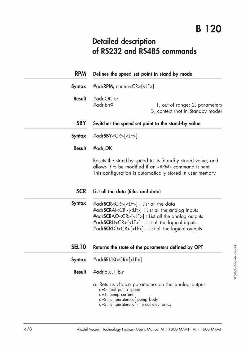
B 120Detailed descriptionof RS232 and RS485 commands
4/8
GB
0074
3 -
Editi
on 0
4 -
June
98
Alcatel Vacuum Technology France - User’s Manual ATH 1300 M/MT - ATH 1600 M/MT
RPM
Syntax
Result
SBY
Syntax
Result
SCR
Syntax
SEL10
Syntax
Result
Defines the speed set point in stand-by mode
#adrRPM, nnnnn<CR>[<LF>]
#adr,OK or#adr,ErrX 1, out of range; 2, parameters
3, context (not in Standby mode)
Switches the speed set point to the stand-by value
#adrSBY<CR>[<LF>]
#adr,OK
Resets the stand-by speed to its Standby stored value, andallows it to be modified if an «RPM» command is sent. This configuration is automatically stored in user memory
List all the data (titles and data)
#adrSCR<CR>[<LF>] : List all the data#adrSCRAI<CR>[<LF>] : List all the analog inputs#adrSCRAO<CR>[<LF>] : List all the analog outputs#adrSCRLI<CR>[<LF>] : List all the logical inputs#adrSCRLO<CR>[<LF>] : List all the logical outputs
Returns the state of the parameters defined by OPT
#adrSEL10<CR>[<LF>]
#adr,a,u,1,b,r
a: Returns choice parameters on the analog outputa=0: real pump speeda=1: pump currenta=2: temperature of pump bodya=3: temperature of internal electronics

B 120Detailed descriptionof RS232 and RS485 commands
5/8
GB
0074
3 -
Editi
on 0
4 -
June
98
Alcatel Vacuum Technology France - User’s Manual ATH 1300 M/MT - ATH 1600 M/MT
SEL10(continued)
Result
SEP
Syntax
Result
Returns the state of the parameters defined by OPT(continued)
u: Returns the choice of temperature unitu=0: degrees Centigradeu=1: degrees Fahrenheit
1: Not used
b: Returns buzzer choiceb=0: whithoutb=1: whith
r: Returns remote choicer=0: remote mode offr=1: remote mode on
#adr,OK
Defines the character which separates the parametersin a reply
#adrSEP,nnn<CR>[<LF>]nnn: 3-digit decimal value of the ascii code of thedesired character (with leading zeros).condition : 000 ≤ nnn ≤ 255
#adr,OK or #adr,ErrX if error
Allows the user to select the character which separatesthe parameters returned by the DLR STA and LEV commands.Default value: comma «,» ascii code = 044If ok, the selected value is automatically stored in usermemory.

B 120Detailed descriptionof RS232 and RS485 commands
6/8
GB
0074
3 -
Editi
on 0
4 -
June
98
Alcatel Vacuum Technology France - User’s Manual ATH 1300 M/MT - ATH 1600 M/MT
SET
Syntax
Result
SPD
Syntax
Result
STA
Syntax
Result
Defines the internal operating parameters
#adrSET10,ccccc<CR>[<LF>] : pump working time (in hours)#adrSET11,eeeee<CR>[<LF>] : electronic working time (in hours)#adrSET13,ddddd<CR>[<LF>] : start relay (max 14459 s,
that is 240 mn59 s)#adrSET14,pppp<CR>[<LF>] : time to venting (max 3559 s,
that is 59 mn 59 s)#adrSET15,qqqq<CR>[<LF>] : venting time (max 3559 s,
that is 59 mn 59 s)#adrSET30,jj<CR>[<LF>] : speed threshold for relay (3 to 50%)#adrSET31,kk<CR>[<LF>] : control temperature (30 to 75°C)#adrSET32,lll<CR>[<LF>] : bearing threshold (0 to 100%)#adrSET33,mmm<CR>[<LF>] : bearing current value (0 to 100%)
#adr,OK or ErrX
Returns the current speed
#adrSPD<CR>[<LF>]
#adr,nnnnn rpm
Returns the status of the internal dynamic parameters
#adrSTA<CR> or STA<CR>
#adr,sss, rrrrr, vvv, www, xxx, yyy, zzz, aa, bbbbb, ccc, ddd,ggggggggggggggggggggggggg<CR>
adr: address
s1: order status
Bit 7 6 5 4 3 2 1 0INH LOCAL STOP (free) REM STDBY START
0 OFF OFF OK OFF OFF OFF1 1 ON ON fault ON ON ON

B 120Detailed descriptionof RS232 and RS485 commands
7/8
GB
0074
3 -
Editi
on 0
4 -
June
98
Alcatel Vacuum Technology France - User’s Manual ATH 1300 M/MT - ATH 1600 M/MT
STA(continued)
Returns the status of the internal dynamic parameters(continued)
rrrrr: speed in rpm zzz: Axial z12vvv: Radial v13 aa: Motor voltage Vwww: Radial w13 bbbbb: Motor current mAxxx: Radial v24 ccc: Pump temp(°C)yyy: Radial w24 ddd: Controller temp (°C)
g 0 = OK 1 = ALERT 2 = FAULT
0123456789101112131415161718192021222324
W01: pow. overheatW02: mot. overheatW03: mot. control
W12: power voltW13: pow. current
W20: bearingW21: act temp.W22: pump temp.
W28: eeprom write
D00: seized pump
D04: hall sensorD05: overc/sensorD06: ext. safetyD11: mag. suspens.
D14: V13D15: W13D16: V24D17: W24D18: Z12D24: bear. changed
D23: pump temp.D25: temp. sensor 1D26: no connectD30: eeprom checkD29: input powerD31: codingD32: no connectedD33: temp. sensor 2
s3: valve status
s2: pump statusBit 7 6 5 4 3 2 1 0
Fault Warning Braking Nom. speed Accele- Start Powertemp. and Temp rating
0 OK OK OFF OFF OFF OFF OFF1 1 fault warn.T ON ON ON ON ON
Bit 7 6 5 4 3 2 1 0At (free) (free) Water Ther- Air Isol.
speed valve mostat inlet valve0 OFF close OFF close close1 1 ON open ON open open

B 120Detailed descriptionof RS232 and RS485 commands
8/8
GB
0074
3 -
Editi
on 0
4 -
June
98
Alcatel Vacuum Technology France - User’s Manual ATH 1300 M/MT - ATH 1600 M/MT
TIT
Syntax
TMP
Syntax
Result
List the data titles
#adrTITAI<CR>[<LF>] : List analog inputs#adrTITLI<CR>[<LF>] : List logical inputs#adrTITLO<CR>[<LF>] : List logical outputs
Defines the operating state of the turbomolecular pump
#adrTMPON<CR>[<LF>] start pump rotation#adrTMPOFF<CR>[<LF>] stop pump
#adr,OK or #adr,Err3 if the pump is already in the staterequested (context error)

C 10Safety instructions
1/1
GB
0074
5 -
Editi
on 0
4 -
Mar
ch 0
0
Alcatel Vacuum Technology France - User’s Manual ATH 1300 M/MT - ATH 1600 M/MT
Before to use the controller, make sure that the mechanical and electricalconnections have been made (see chapter B).If an error message is displayed during operation, see D 20.
The controller should never be switched off as long as the rotor is moving.
It is highly recommended to install:• a screen filter at the pump inlet;• an isolation valve between the chamber to be pumped and the ATH pump;• an isolation valve between the ATH pump and the backing pump.
WARNING
The machines are designed so as not to present a thermal risk for the user’ssafety.However, specific operating conditions can generate temperatures which require particular care to be taken by the user (external surfaces > 70°C).
Avoid moving or causing a shock on a pump in operation. There is a risk of seizing if the pump rotates in an axis perpendicular to its axis of rotation.
An air inlet valve (option) can be connected (see B 40) to ensure the pump’s safety anddurability.As long as the pump is running, the air inlet valve has to be supplied with inert gas.
CAUTION!
In case of maintenance, refer to chapter D10.CAUTION!
WARNING
CAUTION!


C 20Controller start-up
1/2
GB
0173
5 -
Editi
on 0
3 -
Janu
ary
04
Alcatel Vacuum Technology France - User’s Manual ATH 1300 M/MT - ATH 1600 M/MT
The controller performsa self-test and identifies thepumps to which it isconnected.
The initialization time isapproximately 20 seconds.
Display initialization:
The equipment is identified,the program version isdisplayed.
Indicator lights test:they are lit in succession.
The working screen isdisplayed (connected pumpidentification).
CHECKING PROCEDURE
KEYB XX HACT XXXX V3.XX
ATH XXXX XREADY TO START!
Parameter settingaccess
Selection
Validation
• used to access the parameter setting mode.• used to exit the various menus without validating the functions.
• used to move in the menus, or from one parameter to another.• used to select or adjust the value of the selected parameter.
• used to validate the selection of a menu, parameter or value.
• used to exit the menus and return to the pump parameterdisplay.
The message on the display are:• during acceleration, the nominal speed:
“STARTing“ and the green light is OFF.
• pump at speed and pump not at choosen temperature:“WAITING HEAT“ and green light is ON.
• pump at speed and at temperature (minus 3°C): “OK FOR PROCESS“, and the green light is ON.
The parameter setting keys
Once the various electrical connections have been made, setthe main switch on the rear panel to "I".
PREVIOUS
ENTER
STATUS
FAULT

C 20Controller start-up
2/2
GB
0173
5 -
Editi
on 0
3 -
Janu
ary
04
Alcatel Vacuum Technology France - User’s Manual ATH 1300 M/MT - ATH 1600 M/MT
Enter the sub-menus by pressingConfigure the parametersfor the application using
the various menus.
DISPLAY SETUP
Display and/or select the parameters to bemonitored (see C 30).
PREVIOUS
Access the parameterprogramming (see C 30).
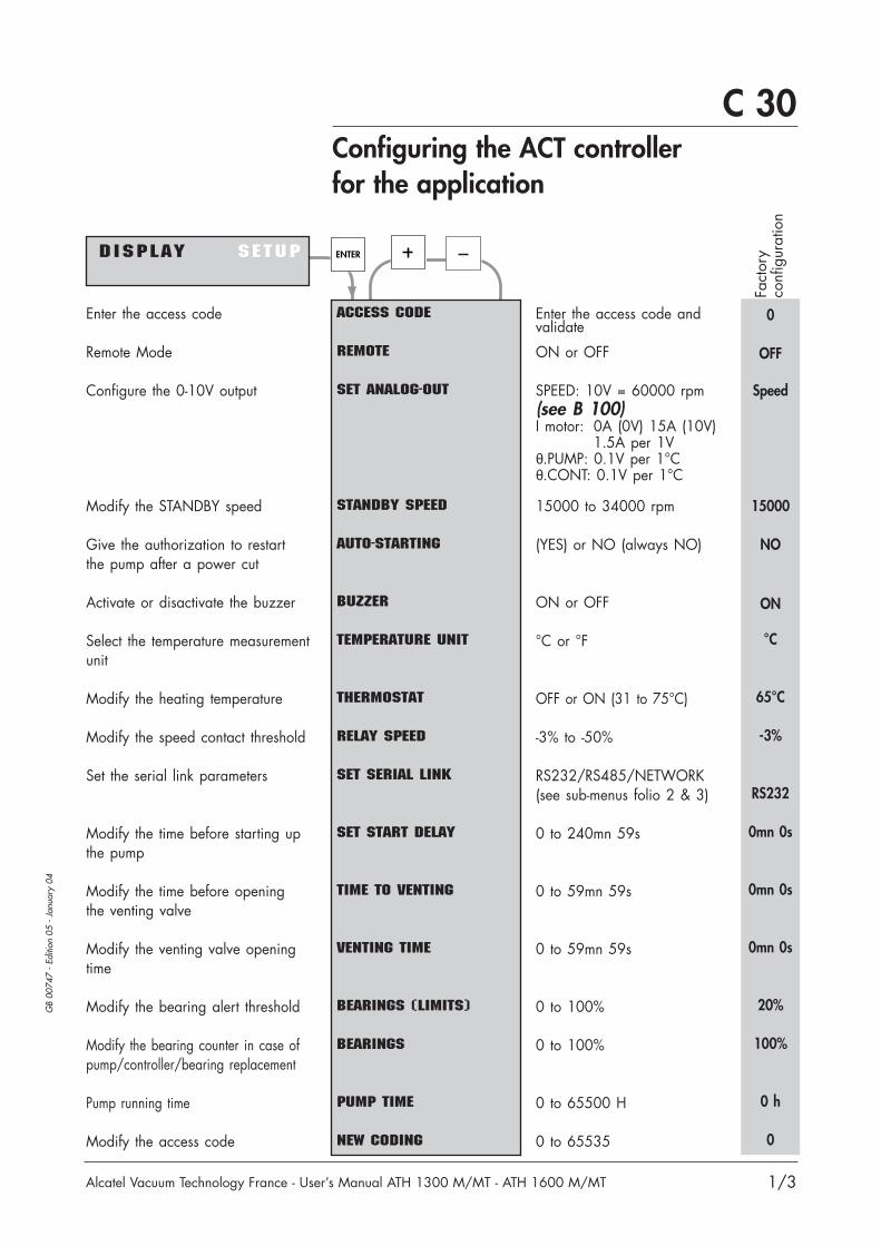
C 30Configuring the ACT controllerfor the application
Alcatel Vacuum Technology France - User’s Manual ATH 1300 M/MT - ATH 1600 M/MT
GB
0074
7 -
Editi
on 0
5 -
Janu
ary
04
1/3
DISPLAY SETUPSETUP
Enter the access code andvalidate
ON or OFF
SPEED: 10V = 60000 rpm(see B 100)I motor: 0A (0V) 15A (10V)
1.5A per 1V θ.PUMP: 0.1V per 1°Cθ.CONT: 0.1V per 1°C
15000 to 34000 rpm
(YES) or NO (always NO)
ON or OFF
°C or °F
OFF or ON (31 to 75°C)
-3% to -50%
RS232/RS485/NETWORK(see sub-menus folio 2 & 3)
0 to 240mn 59s
0 to 59mn 59s
0 to 59mn 59s
0 to 100%
0 to 100%
0 to 65500 H
0 to 65535
0
OFF
Speed
15000
NO
ON
°C
65°C
-3%
RS232
0mn 0s
0mn 0s
0mn 0s
20%
100%
0 h
0
ACCESS CODE
REMOTE
SET ANALOG-OUT
STANDBY SPEED
AUTO-STARTING
BUZZER
TEMPERATURE UNIT
THERMOSTAT
RELAY SPEED
SET SERIAL LINK
SET START DELAY
TIME TO VENTING
VENTING TIME
BEARINGS (LIMITS)
BEARINGS
PUMP TIME
NEW CODING
Fact
ory
conf
igur
atio
n
ENTER
Enter the access code
Remote Mode
Configure the 0-10V output
Modify the STANDBY speed
Give the authorization to restartthe pump after a power cut
Activate or disactivate the buzzer
Select the temperature measurementunit
Modify the heating temperature
Modify the speed contact threshold
Set the serial link parameters
Modify the time before starting upthe pump
Modify the time before openingthe venting valve
Modify the venting valve openingtime
Modify the bearing alert threshold
Modify the bearing counter in case ofpump/controller/bearing replacement
Pump running time
Modify the access code

C 30Configuring the ACT controllerfor the application
Alcatel Vacuum Technology France - User’s Manual ATH 1300 M/MT - ATH 1600 M/MT
GB
0074
7 -
Editi
on 0
5 -
Janu
ary
04
2/3
Serial link setting
ENTER
Transmission speed . . . . . . . Parity . . . . . . . . . . . . . . . . Data length . . . . . . . . . . . . Number of STOP bits . . . . . . Authorizes or does notauthorize the echo ofcharacters received on the linkData separatingcharacter . . . . . . . . . . . . . Number of controller in amultiple link . . . . . . . . . . . . Authorizes transmission at pre-setintervals on the serial link, if ON,Set the transmission interval
Transmission speed . . . . . . . Parity . . . . . . . . . . . . . . . . Data length . . . . . . . . . . . . Number of STOP bits . . . . . . Data separatingcharacter. . . . . . . . . . . . . . Number of controller in amultiple link . . . . . . . . . . . .
Default Setting valuesvalues
9600 bauds 1200 2400 4800 9600None None Even Odd8 bits 7 or 81 bit 1 or 2
ON ON or OFF
44 (comma) 0 to 255
0 0 to 255
OFF ON or OFF0mn1s 0 to 4mn15s
or 255 s
9600 bauds 1200 2400 4800 9600None None Even Odd8 bits 7 or 81 bit 1 or 2
44 (comma) 0 to 255
0 0 to 255
SPEEDPARITYDATA-BITSSTOP-BITSECHO
SEPARATOR
ADDRESS
SET DATA LOGGER
SPEEDPARITYDATA-BITSSTOP-BITSSEPARATOR
ADDRESS
RS 232 R S 4 8 5R S 4 8 5NETWORK
Return to Set start delay
Return to Set start delay
R S 2 3 2R S 2 3 2 RS 485NETWORK
Serial link selectionSET SERIAL L INK

C 30Configuring the ACT controllerfor the application
Alcatel Vacuum Technology France - User’s Manual ATH 1300 M/MT - ATH 1600 M/MT
GB
0074
7 -
Editi
on 0
5 -
Janu
ary
04
3/3
Number of controller in asequence in the case of themultiple link . . . . . . . . . . . .
0 0 to 255ADDRESS
RS 232 RS 485N E T W O R KN E T W O R K
Return to Set start delay
Serial link setting(continued)

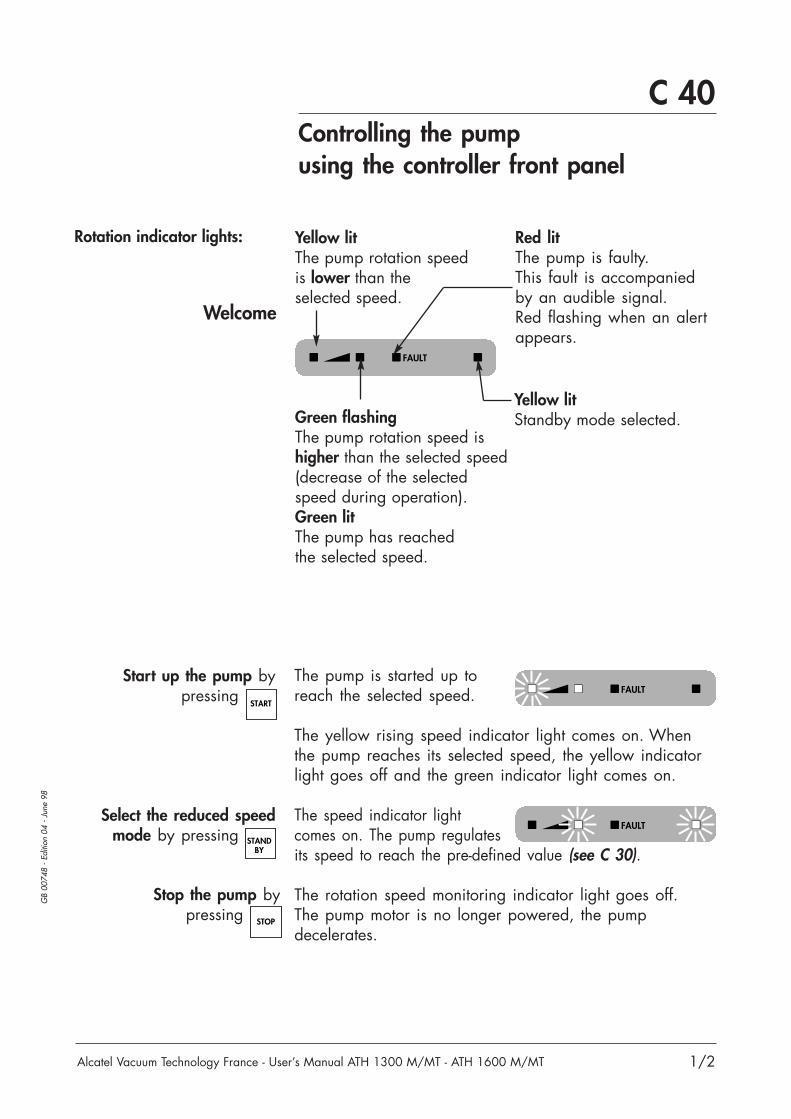
C 40Controlling the pumpusing the controller front panel
Alcatel Vacuum Technology France - User’s Manual ATH 1300 M/MT - ATH 1600 M/MT
Welcome
GB
0074
8 -
Editi
on 0
4 -
June
98
1/2
The pump is started up toreach the selected speed.
The yellow rising speed indicator light comes on. Whenthe pump reaches its selected speed, the yellow indicatorlight goes off and the green indicator light comes on.
The speed indicator lightcomes on. The pump regulatesits speed to reach the pre-defined value (see C 30).
The rotation speed monitoring indicator light goes off.The pump motor is no longer powered, the pumpdecelerates.
Yellow litStandby mode selected.
Start up the pump bypressing
Stop the pump bypressing
Select the reduced speedmode by pressing
Red litThe pump is faulty.This fault is accompaniedby an audible signal.Red flashing when an alertappears.
STANDBY
START
STOP
Yellow litThe pump rotation speed is lower than theselected speed.
Green flashingThe pump rotation speed ishigher than the selected speed(decrease of the selectedspeed during operation).Green litThe pump has reachedthe selected speed.
Rotation indicator lights:
FAULT
FAULT
FAULT

C 40Controlling the pumpusing the controller front panel
Alcatel Vacuum Technology France - User’s Manual ATH 1300 M/MT - ATH 1600 M/MT
Welcome
GB
0074
8 -
Editi
on 0
4 -
June
98
2/2
400H FAULT 1D06:EXTERNAL SAFETY
420H WARNING 1W20:BEARING
ENTER
ENTER
DISPLADISPLAYY SETUP
STATUS F A U LF A U L TTWARNING BEARING
STATUS FAULTW A R N I N GW A R N I N G BEARING
STATUS FAULTWARNING B E A R I N GB E A R I N G
ENTER
ATH 20°C 1 .50AACT 36°C 34000
S T A T U SS T A T U S FAULTWARNING BEARING
S T A T U SS T A T U S FAULTWARNING BEARING
Pump and controller status• pump temperature• pump motor current• controller temperature• pump rotation speed
Successive display of last10 faults• number of hours of pumpoperation when the faultappeared• record number (1 to 10)• fault title
Successive display of last10 alerts• number of hours of pumpoperation when the alertappeared• record number (1 to 10)• alert title
ENTER
ENTER
ENTER
ENTER
ENTER
ENTER
Bearing data• the bearing life time (%) andthe alert threshold (%).
The bearing life time% restant
BEARINGS100.00/20%

C 50
1/4
GB
0173
7 -
Editi
on 0
3 -
Janu
ary
04
Alcatel Vacuum Technology France - User’s Manual ATH 1300 M/MT - ATH 1600 M/MT
In the case of a local mode operation of thecontroller, make sure that the terminal plug (delivered withthe ACT) is connected to the Inputs/Outputs” connector atthe rear of the unit (see B 91 for the wiring of the plug).
C 50Local and remote mode operation
Pumping cyclefrom chamber
at atmospheric pressure
Switch on the controller
Start the pumping by
Open the valve V2
Select the stand-by mode STANDBY
START
V3
ATH ADP
N2
V2
V1
Chamberto be evacuated
The valve V3 is closed and the «FAULT» contact closes.The rotor is levitated.The heating band is powered (for ATH MT).
The primary pumps starts and valve V1 opens(if the primary pumping is controlled by the controller).If the pump start-up time has been programmed (see C 20),the countdown of the time before the pump begins rotatingis displayed on the screen.If the pump start-up time has not been programmed, theprimary pumping system and ATH start up at the same time.
Take care to wire the customer relay in series with«ISOL. VALVE» contact (for a gauge for example).The chamber continues to be pumped until the customeroperating pressure is reached.
The pump reaches the standby speed programmed (see C 30).The standby mode can be selected when pump is stoppedor in rotation.
The controller screendisplays “KEYB“.
Local mode operation
Pumping start
KEYB XX HACT XXXXX V3.XX
ATH XXXXXXREADY TO START!
CAUTION!

C 50Local and remote mode operation
2/4
GB
0173
7 -
Editi
on 0
3 -
Janu
ary
04
Alcatel Vacuum Technology France - User’s Manual ATH 1300 M/MT - ATH 1600 M/MT
The level of vacuum in the chamber is maintained.
The controller displayindicates temporarily:
The time for the delay to open and opening time are 0s.After a STOP signal (or a default), the pump will brakewithout air-inlet. The duration of the rotor slow down untilits complete stop could be more than 30 minutes.No message of venting on the front panel.
It closes before if the rotation of the pump reaches 0 rpmor if there is a START signal.If the setted opening time isreached before the pump reaches 0 rpm, the controller displays:
This closes the primary isolation valve V1 and the primarypump stops. If the ISV contact is connected, V2 closes.The braking of the pump from maximum speed to10000 rpm takes t < 10 min.
Close the valve V2
1st caseNo air inlet valve connected
(standard configurationfrom Alcatel factory)
The customer has to set the delay to open the valve andthe time of opening (see C 30 “Time to venting” or“Venting time”).After a STOP signal (or a default), the pump will brakewithout air-inlet down to 10000 rpm. At 10000 rpm plusthe delay (see C 30), the air inlet valve will open. It staysopen for the chosen opening time (max. 3599s). When the valve is open,there is a message«VENTING» on the frontpanel, during the ventingtime.
2nd caseAir inlet valve connected
Stop the pumping by
(no air inlet valveconnected)
STOP
Pumping stop
KEYB BRK XX H
.................BRAKING.................
KEYB BRK XX H
.................VENTING.................
Close the valve V3
KEYB BRK XX H
.................BRAKING.................
Open the valve V3

Alcatel Vacuum Technology France - User’s Manual ATH 1300 M/MT - ATH 1600 M/MT
C 50
GB
0173
7 -
Editi
on 0
3 -
Janu
ary
04
Local and remote mode operation
3/4
Immediate restarts
Event of a power cut
Short power cuts
If the pump has been stopped by an air inlet, we adviseto limit to 2 the number of immediate restarts per hour.If the pump has been stopped without air inlet, immediaterestarts are not limited.
If a power cut occurs, the rotor remains suspended bythe energy emitted by the motor’s counter-electromotiveforce, until the rotor rotation speed is low enough (around9000 rpm) so that it can rest on the back-up bearingswithout being damaged.
When the rotation speed reaches about 10000 rpm, the controller display indicates:
Otherwise, the minimum speed is reached before thepower is restored:- «ISOL.VALVE» contact is open (V2 closes);- «START» contact is open (V1 closes);- the air inlet valve is open if setted;- the pump lands on its back-up bearings;- the controller is stopped;- the landing’s time counter decreases (see D 10).
The normal start-up procedure is to be resumed after powerhas been restored (see page 1).
If the pump is remote controlled:- disable “Remote Start”;- valid “Remote Stop”;- valid again “Remote Start” (see B 91).
Note: If the power is restored before this minimum speed(9000 rpm) is reached, the pump resumes its initial speedwithout any disturbance. The landing’s time counter doesn’tdecrease.
D 29 : INPUT POWER

Alcatel Vacuum Technology France - User’s Manual ATH 1300 M/MT - ATH 1600 M/MT
C 50Local and remote mode operation
GB
0173
7 -
Editi
on 0
3 -
Janu
ary
04
4/4
Remote mode operation
The START/STOP/STANDBY commands are the same asthose for the local mode.
REM XX HACT XXXXX V3.XX
ATH XXXXXXREADY TO START!
The controller screendisplays “REM“.
In the case of Remote mode operation, the input /output connector has to be wired according to the
remote functions requested (see B 91).Set the controller on “Remote ON” mode (see C 30).
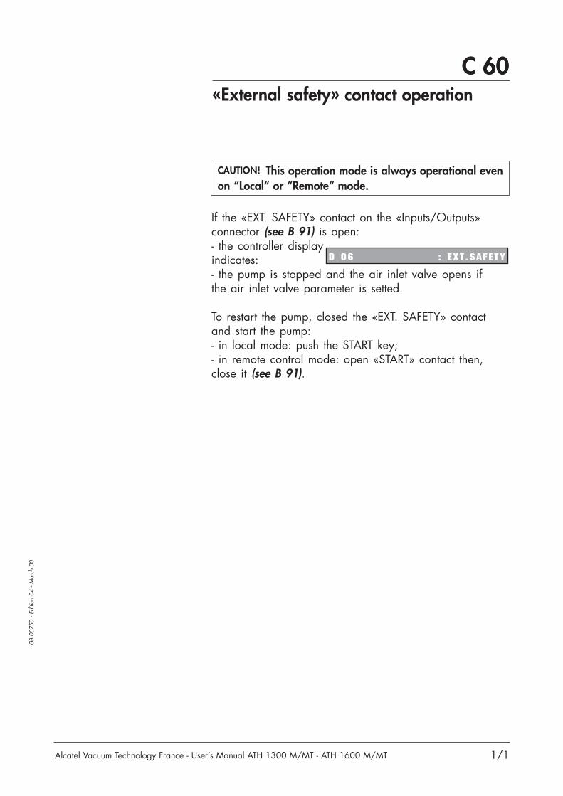
Alcatel Vacuum Technology France - User’s Manual ATH 1300 M/MT - ATH 1600 M/MT
C 60
1/1
GB
0075
0 -
Editi
on 0
4 -
Mar
ch 0
0
C 60«External safety» contact operation
If the «EXT. SAFETY» contact on the «Inputs/Outputs»connector (see B 91) is open:- the controller display indicates:- the pump is stopped and the air inlet valve opens if the air inlet valve parameter is setted.
To restart the pump, closed the «EXT. SAFETY» contactand start the pump:- in local mode: push the START key;- in remote control mode: open «START» contact then,close it (see B 91).
D 06 : EXT .SAFETY
This operation mode is always operational evenon “Local“ or “Remote“ mode.CAUTION!


C 70
Alcatel Vacuum Technology France - User’s Manual ATH 1300 M/MT - ATH 1600 M/MT 1/1
GB
0075
1 -
Editi
on 0
2 -
Mar
ch 0
0
C 70«INH» Inhibit mode operation
“INH” mode desable
The controller doesn’t supply the motor, inhibit theprogressed functions and memorize them. There is no airinlet except if the venting time is on progress.
The actions on START, STOP (KEY or REM) aredesactivated.
This operation mode is always operational evenon “Local” or “Remote” mode.
INH. BRK. XX H
.................BRAKING.......
The controller screendisplays “INH. BRK.“.
“INH” mode valid
The controller power the motor and restore the previousmemorized operating status.
REM XX H
.................STARTING................
The controller screen displays“KEY“ or “REM“.
CAUTION!


GB
0173
9 -
Editi
on 0
7 -
Janu
ary
04
D 10
Alcatel Vacuum Technology France - User’s Manual ATH 1300 M/MT - ATH 1600 M/MT
Safety instructions
1/2
During exhaust maintenance, operator could be in contact with residues from theexhaust port or with contaminated oil which could cause severe injury or death.Always wear gloves, protective glasses and a breathing mask.
Standard precautions before any maintenance operation:Before performing a maintenance operation, switch off the pump by setting themain switch to "0", disconnect the main cable and wait 1 minute before operating on the product.
If this last one remains connected, some components will still be energized.This pump is not equipped with a lock out/tag out (LO/TO) device because it is designatedfor use on process tools.In order to properly secure the pump for installation and maintenance, it is required toproperly lock out/tag out the pump in accordance with OSHA requirements.
After pumping on corrosive or toxic gases, in case of pump return for repair, it is strongly recommended to seal the pump with blank flanges(see instructions on E 00).
WARNING
WARNING
Chemical supplies coming from the tool, water and nitrogen need also to be locked out/tagged out.
WARNING
Before starting any maintenance operations, be sure to check the pumpingconditions: toxicity, corrosion, of the pumped gases.
WARNING
Product tightness is guaranteed upon leaving the factory for normal operatingconditions.It is the responsibility of the user to ensure that the level of tightness is maintained whenpumping dangerous gases.
CAUTION!
Before any intervention on the pump, we advise to prolonge N2 flow for 30mn.CAUTION!
WARNING

GB
0173
9 -
Editi
on 0
7 -
Janu
ary
04
D 10
Alcatel Vacuum Technology France - User’s Manual ATH 1300 M/MT - ATH 1600 M/MT
Safety instructions
2/2
Back-up bearings
The bearing counter
When the pump is running, the rotor is levitated magnetically.There is therefore no friction between moving and fixed parts.
When the pump is stopped from the controller, the back-upbearings are not used. The rotor remains levitated by magneticbearings.
Only the back-up bearings require maintenance: they aredesigned to withstand many accidental shut-downs, or manylandings of the rotor on the bearings at full speed.These accidental shut-downs occur only in exeptionalcircumstances: broken power supply cable, strong shocks,faulty electronics. It is advisable to check the bearingcounter and provide ball bearings maintenance, when needed.
Life time of these bearings depends on the duration andnumber of landing. The initial percentage displayed bythe controller is 100%.When this percentage reaches 0%, the pump can’t restart andthe back-up bearings have to be changed.The decrementation of the counter is done by:- a landing after a magnetic bearing trouble, at full speed,
nearly 20% (ATH 1300 - 1600) per landing; nearly 33% (ATH 2300) per landing;
- a landing at 9000 rpm after a prolonged power failurenearly 0.03%.
However, the decrementation depends on the bearingsrotation duration:- if the braking valve is not connected, or- if the gas supply is closed on it, or- if there are no exhaust or inlet isolation valves.
The bearing alert threshold can be set on the menu (C30). If the bearing life time is smaller than the alert threshold, analert message is displayed:
The internal memory of the controller informs the operatorwhen the bearings require maintenance by displaying:
D 2 4 : B E A R . C H A N G E D
W 2 0 : B E A R I N G S
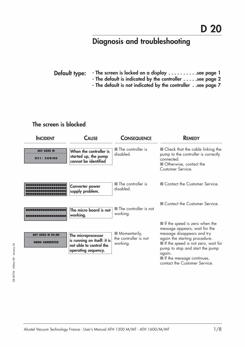
GB
0075
4 -
Editi
on 0
8 -
Janu
ary
04
D 20
Alcatel Vacuum Technology France - User’s Manual ATH 1300 M/MT - ATH 1600/M/MT
Diagnosis and troubleshooting
1/8
Default type:
The screen is blocked
The controller isdisabled.
The controller isdisabled.
The controller is notworking.
Momentarily,the controller is notworking.
ACT xxxx M- - - - - - - - - - - - - - - - - - - - - - - - - - - - - - - - - - - -
D31: CODING
ACT xxxx M V3.00- - - - - - - - - - - - - - - - - - - - - - - - - - - - - - - - - - - -
WDOG CONVERTER
- The screen is locked on a display . . . . . . . . . .see page 1- The default is indicated by the controller . . . . .see page 2- The default is not indicated by the controller . .see page 7
Check that the cable linking thepump to the controller is correctlyconnected. Otherwise, contact theCustomer Service.
Contact the Customer Service.
Contact the Customer Service.
If the speed is zero when themessage appears, wait for themessage disappears and tryagain the starting procedure. If the speed is not zero, wait forpump to stop and start the pumpagain. If the message continues,contact the Customer Service.
INCIDENT CAUSE CONSEQUENCE REMEDY
When the controller isstarted up, the pumpcannot be identified
The microprocessoris running on itself: it isnot able to control theoperating sequency.
Converter powersupply problem.
The micro board is notworking.

GB
0075
4 -
Editi
on 0
8 -
Janu
ary
04
D 20
Alcatel Vacuum Technology France - User’s Manual ATH 1300 M/MT - ATH 1600/M/MT
Diagnosis and troubleshooting
2/8
The "FAULT" contact opens (see B 91).Depending on the defect type:- the "FAULT" signal can be on, for an alarm, and flashingfor an alert;
- the air inlet valve must open;- and the controller can stop the pump.In the following table, we’ll use the symbol:
When a defect appears
Defaults identification:
N
N
N
N
INCIDENT CAUSE CONSEQUENCE REMEDY
D 00:SEIZED PUMP
W 01:POWER
OVERHEAT
W 02:MOTOR
OVERHEAT
W 03:MOTOR
CONTROLOVERHEAT
Pumping cell seized.
The power supplytemperature is outsideauthorized limits.
The stator motortemperature is toohigh.
The frequencyconverter temperatureis too high.
The controller doesn’tsupply the motor.
The controller temporarilystops driving the pumprotation untilthe temperaturedrops back belowthe authorized limit.
The controller temporarilystops driving the pumprotation untilthe temperaturedrops back belowthe authorized limit.
The controller temporarilystops driving the pumprotation untilthe temperaturedrops back belowthe authorized limit.
Check manually that the rotorrotates; otherwise contact theCustomer Service.
Check the power supplyvoltage; Check that the ventilation ofthe controller is operating (airadmissions not blocked).
Reduce the number of start-upsper hour; Reduce the working pressureor the flowrate; For thermostatic pump, checkthat the water valve is opening; Check the water cooling of thepump (check that the water ispresent and the flowrate); Check the purge flowrate.
Reduce the number of start-upsper hour; Reduce the working pressureor the flowrate; Check that the ventilation ofthe controller is operating (airadmissions not blocked).
FAU
LT
The signal lights on The signal light not on
The signal light is flashingY The air inlet valve opensN The air inlet valve doesn’t open
FAULT
OPE
N
OPE
N
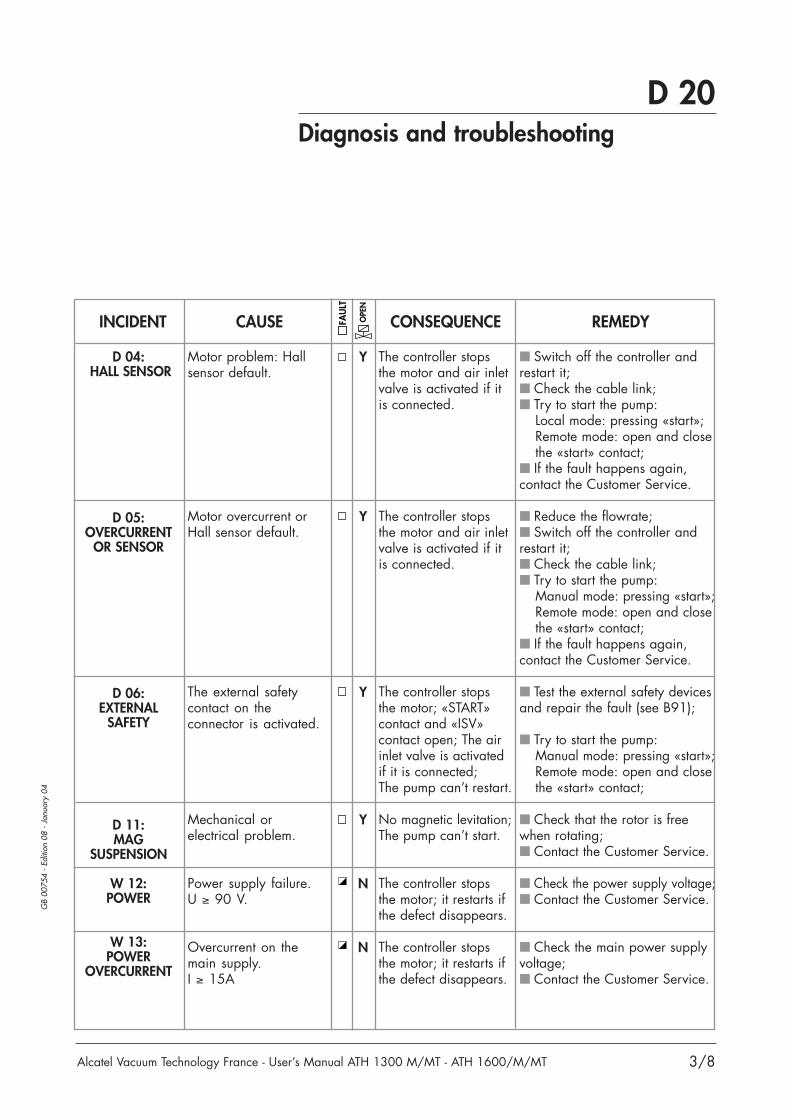
GB
0075
4 -
Editi
on 0
8 -
Janu
ary
04
D 20
Alcatel Vacuum Technology France - User’s Manual ATH 1300 M/MT - ATH 1600/M/MT
Diagnosis and troubleshooting
3/8
Y
Y
Y
Y
N
N
INCIDENT CAUSE CONSEQUENCE REMEDY
D 04:HALL SENSOR
D 05:OVERCURRENT
OR SENSOR
D 06:EXTERNAL
SAFETY
D 11:MAG
SUSPENSION
W 12:POWER
W 13:POWER
OVERCURRENT
Motor problem: Hallsensor default.
Motor overcurrent orHall sensor default.
The external safetycontact on theconnector is activated.
Mechanical orelectrical problem.
Power supply failure.U ≥ 90 V.
Overcurrent on themain supply.I ≥ 15A
The controller stops the motor and air inletvalve is activated if itis connected.
The controller stops the motor and air inletvalve is activated if itis connected.
The controller stops the motor; «START»contact and «ISV»contact open; The airinlet valve is activatedif it is connected;The pump can’t restart.
No magnetic levitation;The pump can’t start.
The controller stops the motor; it restarts ifthe defect disappears.
The controller stops the motor; it restarts ifthe defect disappears.
Switch off the controller andrestart it; Check the cable link; Try to start the pump:
Local mode: pressing «start»;Remote mode: open and closethe «start» contact;
If the fault happens again,contact the Customer Service.
Reduce the flowrate; Switch off the controller andrestart it; Check the cable link; Try to start the pump:
Manual mode: pressing «start»;Remote mode: open and closethe «start» contact;
If the fault happens again,contact the Customer Service.
Test the external safety devicesand repair the fault (see B91);
Try to start the pump:Manual mode: pressing «start»;Remote mode: open and closethe «start» contact;
Check that the rotor is freewhen rotating; Contact the Customer Service.
Check the power supply voltage; Contact the Customer Service.
Check the main power supplyvoltage; Contact the Customer Service.
FAU
LT
OPE
N

GB
0075
4 -
Editi
on 0
8 -
Janu
ary
04
D 20
Alcatel Vacuum Technology France - User’s Manual ATH 1300 M/MT - ATH 1600/M/MT
Diagnosis and troubleshooting
4/8
YYYYY
N
N
N
N
Y
Y
Y
INCIDENT CAUSE CONSEQUENCE REMEDY
D 14: V 13D 15: W 13D 16: V 24D 17: W 24D 18: Z 12
W 20:BEARING
W 21:ACT TEMP.
W 22:PUMP TEMP.
D 23:PUMP TEMP.
D 24:BEARINGS MUST
BE CHANGED
D 25:TEMP SENSOR-1
D 26:NO CONNECT
The rotor positionoutside authorizedlimits.
The bearing life time issmaller than the alertthreshold
The controllertemperature exceedsthe authorized limit60°C.
The pump temperatureexceeds the authorizedlimit 80°C.
The pump temperatureexceeds the authorizedlimit T ≥ 90°C.
The authorized limit forthe number of landingson the emergencybearings has beenreached.
Temperature sensor-1failure.
Wiring fault betweenpump and controller(connection cable).
The controller stops the motor;«START» contact and«ISV» contact open;The air inlet valve isactivated if it is connec-ted;The pump can’t restart.
Another landing on the bearings ispossible
The controller stops the motor;The pump can’t restart.
The controller stops the pump.
The controller stopsthe motor when thetemperature is below30°C. Then the motorstarts again.
The pump can’t restart.
The controller displaythe default but itdoesn’t stop the motor;PUMP -TEMP1 = 0°C.
The pump can’t start.
Check that there are novibrations on the pump frame; Check that the attachments arecorrectly fastened; If the message disappears, tryto start the pump; If the fault happens again,contact the Customer Service.
Contact the customer service toreplace the ball bearings.
Check that the ventilation is operating (air admissions notblocked); Provide more space aroundthe controller.
Check that the pump coolingdevice is running.
W 22
Call the Customer Service tochange the emergency bearings.
Call the Customer Service.
Check that the cable iscorrectly locked to the pump andthe controller; If the fault appears again, callthe Customer Service.
FAU
LT
OPE
N

GB
0075
4 -
Editi
on 0
8 -
Janu
ary
04
D 20
Alcatel Vacuum Technology France - User’s Manual ATH 1300 M/MT - ATH 1600/M/MT
Diagnosis and troubleshooting
5/8
N
Y
N
N
N
INCIDENT CAUSE CONSEQUENCE REMEDY
W 28:DISABLE
EEPROM WRITE
D 29:INPUT POWER
D 30:EEPROM
CHECKSUM
D 31:CODING
D 32:C. INSIDE
Memory problem.
Main power failure.
Memory erased.
Incompatibility betweenthe pump and thecontroller.
Controller inside wiringdisconnected.
The controller doesn’tstop the motor and the data is not saved.
Imminent landing.
The pump doesn’t start.
The pump doesn’t start.
The pump doesn’t start
Reinitialize the controller withmain switch 0/1 when the pumpis stopped. If the fault appears again,contact the Customer Service.
Check that the power supply ispresent, otherwise see D 20 7/8; Contact the Customer Service.
Contact the Customer Service.
Replace the pump model orcontroller:ATH 2300 M and ACT 2300 M,
orATH 1300 M and ACT 1300 M.
orATH 1600 M and ACT 1300 M.
FAU
LT
OPE
N
Check that the cable betweenpump and controller is correctlyconnected.
Replace the pump model orcontroller:ATH 2300 M and ACT 2300 M, orATH 1300 M and ACT 1300 M, orATH 1600 M and ACT 1300 M.
Pump stopped, switch off thecontroller and start again; Contact the Customer Service
Several defects appear:
INCIDENT CAUSE REMEDY
D 04 - D 05 - D 11D 25 - D 26 - D 31
The pump is not connected tothe controller.
D 11 - D 31Incompatibility between thepump and the controller.
D 04 - D 05 Motor information failure.

GB
0075
4 -
Editi
on 0
8 -
Janu
ary
04
D 20
Alcatel Vacuum Technology France - User’s Manual ATH 1300 M/MT - ATH 1600/M/MT
Diagnosis and troubleshooting
6/8
Default is not indicatedby the controller
Check that the controller ispowered. Check that the power voltageis between 100 V -15% and120 V +10% or between200 V -15% and 240 V +10%. Check the fuses: 2 fuses (16 A) under the controller.
Contact the Customer Service.
Pump stopped, reinitialize the controller with the mainswitch (0/1). Contact the Customer Service.
Change the cable linkbetween the pump and thecontroller. Contact the Customer Service.
Check that the pump is rigidlyfixed to the frame; Check that there are novibrations on the pump frame; Check that the attachment are correctly fastened(Problem can be caused by ananti-vibration flagstone); Contact the Customer Service.
INCIDENT CAUSE REMEDY
No event occursafter power on
Isolate the product fromthe various energysources before any
maintenance operations.
No mains current
The ATH only starts-up inSTANDBY mode
Electronic problem
The motor power loadstays below 100W
Electronic problem
Up to 7000 rpm,the pump starts to vibrate
Mechanical problem

GB
0075
4 -
Editi
on 0
8 -
Janu
ary
04
D 20
Alcatel Vacuum Technology France - User’s Manual ATH 1300 M/MT - ATH 1600/M/MT
Diagnosis and troubleshooting
7/8
Close the chamber isolation valve. Start the pump. If the pumpreaches the expected speed:the leak is in the chamber.
If the valve is controlled by the«START» contact, check that thevalve opens when the «START»command is selected. If the valve doesn’t open,check the coil and electricalconnection. Check on the controller theclosing of the «START» contact(valve disconnected). If the contact doesn’t close,contact the Customer Service.
Install a gauge at the primarypump inlet and check its vacuumlimit (P ≤ 1.10-1 mbar).
ACT powered, valvedisconnected from the controller,check the «AIR INLET» outputvoltage (0V). Check the air inlet valve operation (NC). If the output is defective,contact the Customer Service.
Replace the valve by a blank-off.Take care that the pump is notprotected now. Start the pump. If the pump reaches its speed,stop it quickly and exchange thevalve. If not, contact the CustomerService.
INCIDENT CAUSE REMEDY
The pump doesn't reachthe expected speed
Leak on the installation
Exhaust isolation valvestays closed
Defective rough pumping
Air inlet valve stays opened
Leak on the air inlet valve
NO
NO
NO
NO

GB
0075
4 -
Editi
on 0
8 -
Janu
ary
04
D 20
Alcatel Vacuum Technology France - User’s Manual ATH 1300 M/MT - ATH 1600/M/MT
Diagnosis and troubleshooting
8/8
Close the water line.If the temperature increases,there is a leak on the water line.
Check that the«THERMOSTAT» contacts areclosed.
Check the heating bandpower supply.
Contact the Customer Service.
Check that the water valveoutput is supplied with 12 VDCand the water valve is notopened.
INCIDENT CAUSE REMEDY
The thermostatictemperature is not reached The heating band doesn't
heat
“… waiting HEAT…“after 1 h 30
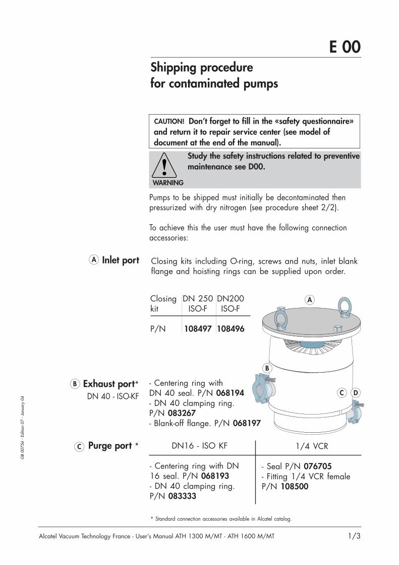
Don’t forget to fill in the «safety questionnaire»and return it to repair service center (see model of document at the end of the manual).
GB
0075
6 -
Editi
on 0
7 -
Janu
ary
04
E 00
Alcatel Vacuum Technology France - User’s Manual ATH 1300 M/MT - ATH 1600 M/MT
Shipping procedurefor contaminated pumps
1/3
Pumps to be shipped must initially be decontaminated thenpressurized with dry nitrogen (see procedure sheet 2/2).
To achieve this the user must have the following connectionaccessories:
Inlet port
Exhaust port*DN 40 - ISO-KF
Purge port * DN16 - ISO KF
- Centering ring with DN16 seal. P/N 068193- DN 40 clamping ring.P/N 083333
* Standard connection accessories available in Alcatel catalog.
A
B
C D
A
B
C
Study the safety instructions related to preventivemaintenance see D00.
WARNING
CAUTION!
- Centering ring withDN 40 seal. P/N 068194- DN 40 clamping ring.P/N 083267- Blank-off flange. P/N 068197
Closing kits including O-ring, screws and nuts, inlet blankflange and hoisting rings can be supplied upon order.
1/4 VCR
- Seal P/N 076705- Fitting 1/4 VCR femaleP/N 108500
Closing DN 250 DN200kit ISO-F ISO-F
P/N 108497 108496

GB
0075
6 -
Editi
on 0
7 -
Janu
ary
04
E 00
Alcatel Vacuum Technology France - User’s Manual ATH 1300 M/MT - ATH 1600 M/MT
Shipping procedurefor contaminated pumps
2/3
Roughdecontamination
procedure
The pump must be disconnected from its installation andisolated electrically.
General sweeping1 Fit the DN 16 blank flangewith anti-suckback valve onthe purge connector (or1/4 VCR).
Sweep with dry nitrogen**using the injector at anabsolute pressure of 1.1 to1.5 bar for 30 minutes.
Install the pump under a suction hood.It must remain there throughout the operation.
Purge / inletsweeping
2 Fit the DN 40 blank flangeon the pump exhaust port.
Sweep with dry nitrogen**for 10 minutes.
Stop the nitrogen flow.
* Standard connection accessories available in Alcatel catalog.** Characteristics of dry nitrogen: see B 50.
30’
10’
N2
N2
WARNING
Required accessorieson purge port to
maintain the pressure*
D - DN 16 1/8 BSPT Flange with anti-suckback valve P/N A458805- Injector P/N 106859
Note: Pressurization kits include connecting accessories forinlet, exhaust and purge ports, plus an injector.
- Kit DN200-ISO-F + Purge DN 16 P/N 108499- Kit HDPCVD DN250-ISO-F + Purge 1/4 VCR P/N 108498
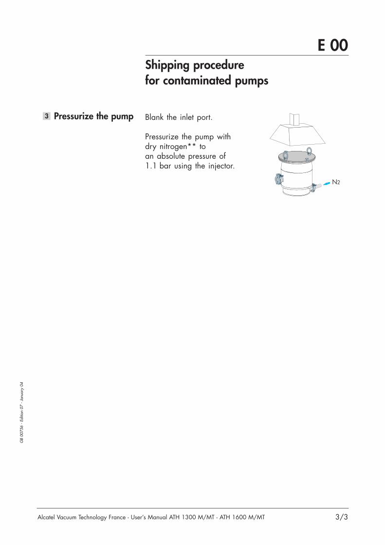
GB
0075
6 -
Editi
on 0
7 -
Janu
ary
04
E 00
Alcatel Vacuum Technology France - User’s Manual ATH 1300 M/MT - ATH 1600 M/MT
Shipping procedurefor contaminated pumps
3/3
Pressurize the pump3 Blank the inlet port.
Pressurize the pump withdry nitrogen** to an absolute pressure of1.1 bar using the injector.
N2


GB
0139
0 -
Editi
on 0
2 -
Sept
embe
r 03
F 00
Alcatel Vacuum Technology France - User’s Manual ATH 1300 M/MT - ATH 1600 M/MT
Spare parts - Instructions of use
1/1
Replacement of partsand use of non genuine
pars
Our products are designed to comply with current ECregulations and guarantee optimal operating conditions,with maximum safety conditions for the user.
Any modification of the product made by the user maylead to non-compliance with the regulations, and affectthe performance of the product and the user’s safety.
Replacement of defective components with non-genuineparts may jeopardize the safety conditions of theequipment. As a result, the EC declaration of conformitybecomes null and AVTF withdraws responsibility for suchoperations.
Counterfeiting and unfair trading of parts are condemnedunder the civil and criminal laws.
AVTF urges users not to take parts in the use of“imitations”, or the misappropriation and pirating ofintellectual property.
AVTF supplies maintenance components, spare parts orkits to perform the maintenance of its products (seechapter F).

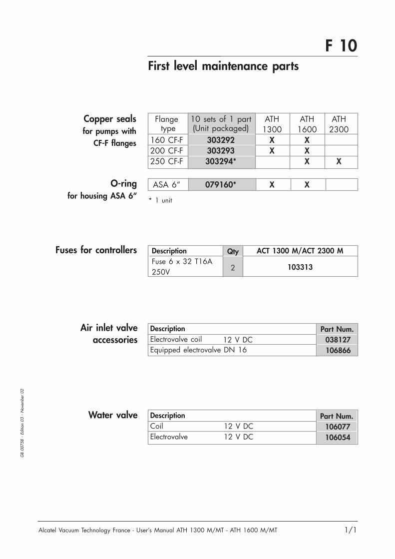
Alcatel Vacuum Technology France - User’s Manual ATH 1300 M/MT - ATH 1600 M/MT
GB
0075
8 -
Editi
on 0
3 -
Nov
embe
r 02
1/1
First level maintenance partsF 10
Part Num.038127106866
DescriptionElectrovalve coilEquipped electrovalve DN 16
12 V DC
ACT 1300 M/ACT 2300 MDescriptionFuse 6 x 32 T16A250V
Fuses for controllers
Copper sealsfor pumps with
CF-F flanges
Qty
2
Air inlet valveaccessories
Flange 10 sets of 1 part ATH ATH ATHtype (Unit packaged) 1300 1600 2300
160 CF-F 303292 X X200 CF-F 303293 X X250 CF-F 303294* X X
ASA 6“ 079160* X X
* 1 unit
Part Num.106077106054
12 V DC12 V DC
Water valve
103313
DescriptionCoilElectrovalve
O-ringfor housing ASA 6“


G 10Pumping curves
Alcatel Vacuum Technology France - User’s Manual ATH 1300 M/MT - ATH 1600 M/MT
GB
0076
0 -
Editi
on 0
2 -
Sept
embe
r 99
1/2
Inlet pressure (Pa)
Inlet pressure (mbar)
Pumping speed (l/s)
0
500400
300
200100
900
1000
11001200
1500
1300
1400
800
700
600
10-5 10-4 10-310-6 10-2 10-1 1011
10-4 10-3 10-2 10-1 1 101 103102
Pumping speed versus inlet pressure
Upper limitsfor continuous operation
ATH 1300 M, DN 200ATH 1600 M, DN 200N2
H2
N2
H2

G 10Pumping curves
Alcatel Vacuum Technology France - User’s Manual ATH 1300 M/MT - ATH 1600 M/MT
GB
0076
0 -
Editi
on 0
2 -
Sept
embe
r 99
2/2
Inlet pressure (Pa)
Inlet pressure (mbar)
Flow rate(sccm)
1
10
100
1000
10000
10-310-4 10-2 110-1 101
10-110-2 1 101 103102
Flow rate versus inlet pressure
Gas : N2
Upper limitsfor continuous operation
ATH 1300 M, DN 200ATH 1600 M, DN 200

G 11
1/2
GB
0076
1 -
Editi
on 0
6 -
July
03
Alcatel Vacuum Technology France - User’s Manual ATH 1300 M/MT - ATH 1600 M/MT
You wish to return an Alcatel vacuum pump or helium leak detector for maintenance. The equipment will bedismantled and possibly cleaned by a technican from our Service Centre.In order to ensure the effective safety of our staff and protection of the environment, we need to know the typesof gas or substances with which the pump or leak detector has been used.This will enable us to take the appropriate safety measures.
The following page contains a questionnaire that you can use for this purpose. This procedure complies with the European Community’s L360 directives and articles L231 and R231 of the French Labour Code.
We wish to draw your attention to the following points: The risk may be of the following nature:- Chemical: danger to health, risks of explosion, fire, risks for the environment. Please indicate the chemical
formula and name of the gases or substances that have been in contact with the equipment (pump orhelium detector).
- Biological: pathogenic germs, micro-organisms (bacteria, viruses, etc.) classes 1 to 4 and group E. We are currently unable to deal with contamination of this sort without risk to the safery of our staff. If yourequipment has been contaminated in this way, contact us so that we can try to find a solution together.
- Radioactive: contact us in this case.
Attention!
In the event of chemical contamination, please indicate the following gases or substances:
- gases (or substances) introduced into the reactor and which may be found at the exhaust (A),
- gases (or substances) resulting from the reaction or process (B),
- gases (or substances) that may possibly be formed inside the pump (due to a thermodynamic or chemicalreaction, condensation, deposition, precipitation, etc.) (C)
Precautions need to be taken before transferring contaminated pumps.Please contact customer service for recommendations.
Procedure for returning ALCATEL vacuum pumps and helium leak detectors
SAFETY QUESTIONNAIRE
Gasesintroduced
AReator Pump or pump unit
Substanced producedby reaction
ExhaustABC
BC
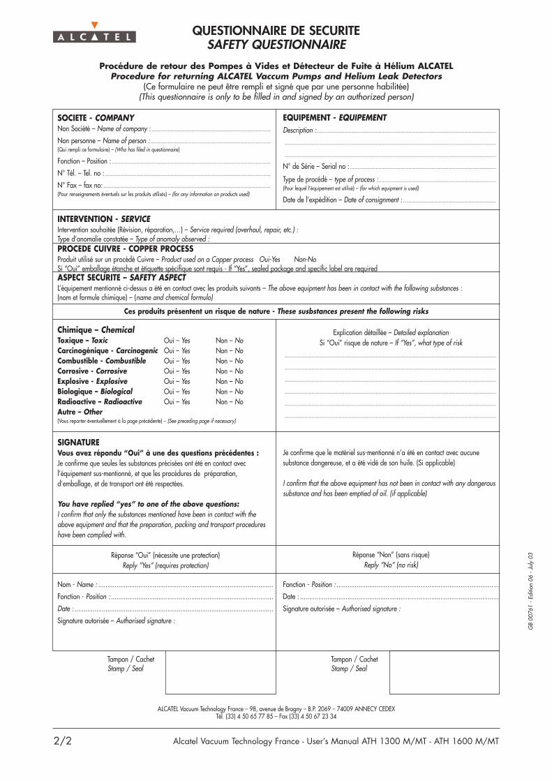
2/2
GB
0076
1 -
Editi
on 0
6 -
July
03
Alcatel Vacuum Technology France - User’s Manual ATH 1300 M/MT - ATH 1600 M/MT
QUESTIONNAIRE DE SECURITESAFETY QUESTIONNAIRE
Procédure de retour des Pompes à Vides et Détecteur de Fuite à Hélium ALCATELProcedure for returning ALCATEL Vaccum Pumps and Helium Leak Detectors
(Ce formulaire ne peut être rempli et signé que par une personne habilitée)(This questionnaire is only to be filled in and signed by an authorized person)
SOCIETE - COMPANYNon Société – Name of company : .......................................................................................
Non personne – Name of person :........................................................................................(Qui rempli ce formulaire) – (Who has filed in questionnaire)
Fonction – Position : ....................................................................................................................
N° Tél. – Tel. no : .........................................................................................................................
N° Fax – fax no: ..........................................................................................................................(Pour renseignements éventuels sur les produits utilisés) – (for any information on products used)
Chimique – ChemicalToxique – Toxic Oui – Yes Non – NoCarcinogénique - Carcinogenic Oui – Yes Non – NoCombustible - Combustible Oui – Yes Non – NoCorrosive - Corrosive Oui – Yes Non – NoExplosive - Explosive Oui – Yes Non – NoBiologique – Biological Oui – Yes Non – NoRadioactive – Radioactive Oui – Yes Non – NoAutre – Other(Vous reporter éventuellement à la page précédente) – (See preceding page if necessary)
Je confirme que le matériel sus-mentionné n’a été en contact avec aucunesubstance dangereuse, et a été vidé de son huile. (Si applicable)
I confirm that the above equipment has not been in contact with any dangeroussubstance and has been emptied of oil. (if applicable)
Réponse “Non” (sans risque)Reply “No“ (no risk)
Fonction - Position : .........................................................................................
Date : .............................................................................................................
Signature autorisée – Authorised signature :
SIGNATUREVous avez répondu “Oui” à une des questions précédentes :Je confirme que seules les substances précisées ont été en contact avecl’équipement sus-mentionné, et que les procédures de préparation,d’emballage, et de transport ont été respectées.
You have replied “yes” to one of the above questions:I confirm that only the substances mentioned have been in contact with theabove equipment and that the preparation, packing and transport procedureshave been complied with.
Réponse “Oui” (nécessite une protection)Reply “Yes“ (requires protection)
Nom - Name : ................................................................................................
Fonction - Position : .........................................................................................
Date : .............................................................................................................
Signature autorisée – Authorised signature :
ALCATEL Vacuum Technology France – 98, avenue de Brogny – B.P. 2069 – 74009 ANNECY CEDEXTél. (33) 4 50 65 77 85 – Fax (33) 4 50 67 23 34
EQUIPEMENT - EQUIPEMENTDescription : ...................................................................................................................................
...........................................................................................................................................................
...........................................................................................................................................................
N° de Série – Serial no :...........................................................................................................
Type de procédé – type of process :......................................................................................(Pour lequel l’équipement est utilisé) – (for which equipment is used)
Date de l’expédition – Date of consignment : ....................................................................
Explication détaillée – Detailed explanationSi “Oui” risque de nature – If “Yes”, what type of risk
...........................................................................................................................................................
...........................................................................................................................................................
...........................................................................................................................................................
...........................................................................................................................................................
...........................................................................................................................................................
...........................................................................................................................................................
Tampon / CachetStamp / Seal
Tampon / CachetStamp / Seal
INTERVENTION - SERVICEIntervention souhaitée (Révision, réparation,…) – Service required (overhaul, repair, etc.) :Type d’anomalie constatée – Type of anomaly observed :PROCEDE CUIVRE - COPPER PROCESSProduit utilisé sur un procédé Cuivre – Product used on a Copper process Oui-Yes Non-NoSi “Oui” emballage étanche et étiquette spécifique sont requis - If “Yes”, sealed package and specific label are requiredASPECT SECURITE – SAFETY ASPECTL’équipement mentionné ci-dessus a été en contact avec les produits suivants – The above equipment has been in contact with the following substances :(nom et formule chimique) – (name and chemical formulo)
Ces produits présentent un risque de nature - These susbstances present the following risks

G 100
1/1
GB
0232
6 -
Editi
on 0
1- J
anua
ry 0
4
Alcatel Vacuum Technology France - User’s Manual ATH 1300 M/MT - ATH 1600 M/MT


![TIRATEX · 1300 · 1600 · 2019. 8. 13. · COMPETENCE IN WOVEN BAGS TIRATEX Tape stretching line TIRATEX 1300 1600 Working width up to [mm] 1.300 1.600 Production speed up to [m/min]](https://img.pdfslide.us/doc/110x75/60b3a4f255f62605bf0c4a3f/tiratex-1300-1600-2019-8-13-competence-in-woven-bags-tiratex-tape-stretching.jpg)