Embed Size (px)
Citation preview
CHASSIS - U250E AUTOMATIC TRANSAXLE
259LSK03
Viscosity
High
Reduced Viscosity
High Temperature
: ATF Type T-IV: ATF WS
CH-8
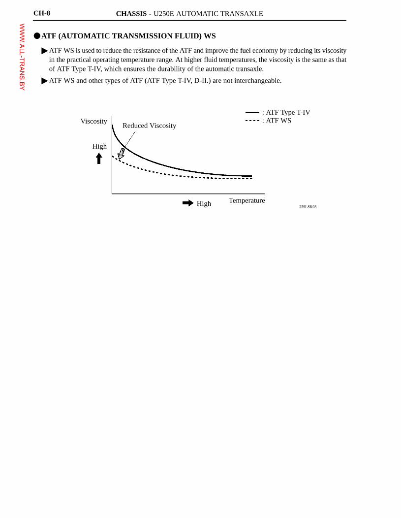
�ATF (AUTOMATIC TRANSMISSION FLUID) WS
� ATF WS is used to reduce the resistance of the ATF and improve the fuel economy by reducing its viscosityin the practical operating temperature range. At higher fluid temperatures, the viscosity is the same as thatof ATF Type T-IV, which ensures the durability of the automatic transaxle.
� ATF WS and other types of ATF (ATF Type T-IV, D-II.) are not interchangeable.
WWW.ALL-TR
ANS.BY
CHASSIS - U250E AUTOMATIC TRANSAXLE
025CH01Y
CH-6
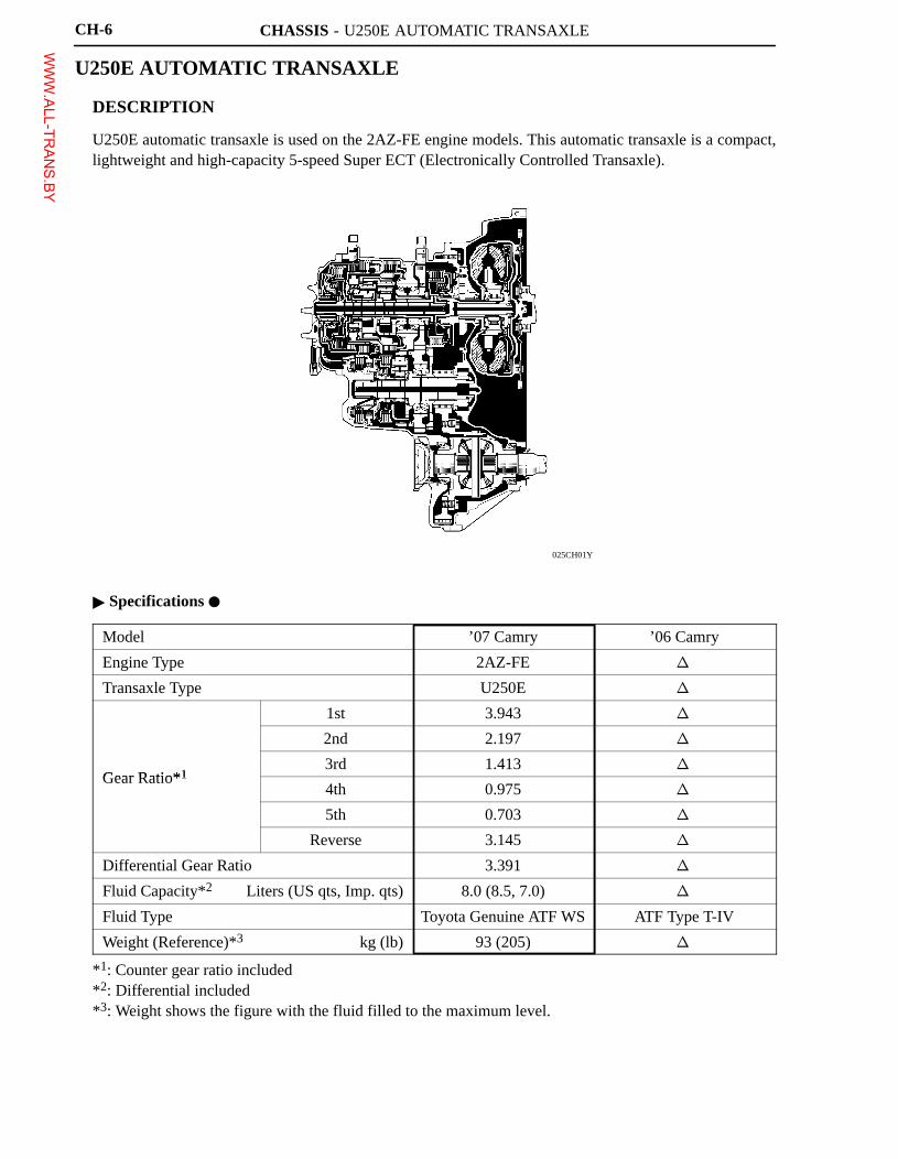
U250E AUTOMATIC TRANSAXLE
�DESCRIPTION
U250E automatic transaxle is used on the 2AZ-FE engine models. This automatic transaxle is a compact,lightweight and high-capacity 5-speed Super ECT (Electronically Controlled Transaxle).
� Specifications �
Model ’07 Camry ’06 Camry
Engine Type 2AZ-FE �
Transaxle Type U250E �
1st 3.943 �
2nd 2.197 �
Gear Ratio*13rd 1.413 �
Gear Ratio*14th 0.975 �
5th 0.703 �
Reverse 3.145 �
Differential Gear Ratio 3.391 �
Fluid Capacity*2 Liters (US qts, Imp. qts) 8.0 (8.5, 7.0) �
Fluid Type Toyota Genuine ATF WS ATF Type T-IV
Weight (Reference)*3 kg (lb) 93 (205) �
*1: Counter gear ratio included*2: Differential included*3: Weight shows the figure with the fluid filled to the maximum level.
WWW.ALL-TR
ANS.BY
CHASSIS - U250E AUTOMATIC TRANSAXLE
025CH02Y
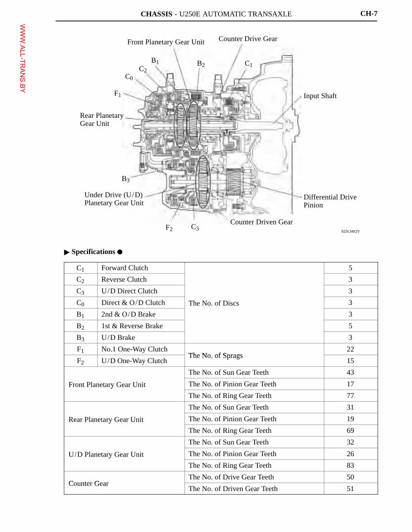
Front Planetary Gear Unit
F1
C0
C2
B1 B2 C1
Rear Planetary Gear Unit
Counter Drive Gear
Input Shaft
Differential Drive Pinion
Counter Driven GearC3F2
B3
Under Drive (U/D) Planetary Gear Unit
CH-7
� Specifications �
C1 Forward Clutch 5
C2 Reverse Clutch 3
C3 U/D Direct Clutch 3
C0 Direct & O/D Clutch The No. of Discs 3
B1 2nd & O/D Brake 3
B2 1st & Reverse Brake 5
B3 U/D Brake 3
F1 No.1 One-Way ClutchThe No of Sprags
22
F2 U/D One-Way ClutchThe No. of Sprags
15
The No. of Sun Gear Teeth 43
Front Planetary Gear Unit The No. of Pinion Gear Teeth 17y
The No. of Ring Gear Teeth 77
The No. of Sun Gear Teeth 31
Rear Planetary Gear Unit The No. of Pinion Gear Teeth 19y
The No. of Ring Gear Teeth 69
The No. of Sun Gear Teeth 32
U/D Planetary Gear Unit The No. of Pinion Gear Teeth 26y
The No. of Ring Gear Teeth 83
Counter GearThe No. of Drive Gear Teeth 50
Counter GearThe No. of Driven Gear Teeth 51
WWW.ALL-TR
ANS.BY
CHASSIS - U250E AUTOMATIC TRANSAXLE CH-23
�ELECTRONIC CONTROL SYSTEM
1. General
The electronic control system of the U250E automatic transaxle consists of the control listed below.
System Outline
Shift Timing ControlThe ECM sends current to 3 solenoid valves (SL1, SL2, and SL3) basedon signals from each sensor and shifts the gear.
Clutch Pressure Control(See page CH-28)
� Controls the pressure that is applied directly to B1 brake, C0 and C1clutches by actuating 3 solenoid valves (SL1, SL2, and SL3) inaccordance with ECM signals.
� 3 solenoid valves (SL1, SL2, and SL3) minutely control the clutchpressure in accordance with the engine output and drivingconditions.
Line Pressure Optimal Control(See page CH-29)
Actuates the solenoid valve SLT to control the line pressure inaccordance with information from the ECM and the operatingconditions of the transaxle.
Shifting Control in Uphill /Downhill Traveling(See page CH-30)
Controls to restrict the 4th or 5th upshift or to provide appropriateengine braking by the ECM to determine whether the vehicle istraveling uphill or downhill.
Lock-up Timing ControlThe ECM sends current to the solenoid valves DSL and SL2 based onsignals from each sensor and engages or disengages the lock-up clutch.
Flex Lock-up Clutch Control(See page CH-31)
Controls the solenoid valve SL2 and DSL, provides an intermediatemode between the ON/OFF operation of the lock-up clutch, andincrease the operating range of the lock-up clutch to improve fueleconomy.
Engine Torque ControlRetards the engine ignition timing temporarily to improve shift feelingduring up or down shifting.
“N” to “D” Squat ControlWhen the shift lever is shifted from “N” to “D” position, the gear istemporarily shifted to 3rd and then to 1st to reduce vehicle squat.
Diagnosis(See page CH-32)
When the ECM detects a malfunction, the ECM makes a diagnosis andmemorizes the malfunctioning part.
Fail-safe(See page CH-32)
Even if a malfunction is detected in the sensors or solenoids, the ECMactivates fail-safe control to prevent the vehicle’s drivability frombeing significantly affected.
WWW.ALL-TR
ANS.BY
CHASSIS - U250E AUTOMATIC TRANSAXLE
025CH12Y
MASS AIR FLOW METER
ENGINE COOLANTTEMP. SENSOR
CRANKSHAFTPOSITION SENSOR
THROTTLE POSITIONSENSOR
ACCELERATOR PEDALPOSITION SENSOR
INPUT TURBINESPEED SENSOR
COUNTER GEARSPEED SENSOR
ATF TEMP. SENSOR
STOP LIGHT SWITCH
STARTER RELAY(Starter Signal)
PARK/NEUTRALPOSITION SWITCH
TRANSMISSIONCONTROL SWITCH
VG
THW
NE
VTA1VTA2
VPAVPA2
NT
NC
THO1
STP
STA
NSW
P,R,N,D,3,2
4,L
ECM
SL1
SL2
SL3
SLT
S4
DSL
SR
IGT1�4
IGF1
CANH,CANL
WSPD
SOLENOID VALVE SL1
SOLENOID VALVE SL2
SOLENOID VALVE SL3
SOLENOID VALVE SLT
SOLENOID VALVE S4
SOLENOID VALVE DSL
SOLENOID VALVE SR
IGNITION COILS
DLC3
CAN (CAN No.1 Bus)
COMBINATION METER
Shift Position Indicator Light
MILVehicle Speed Signal
CH-24
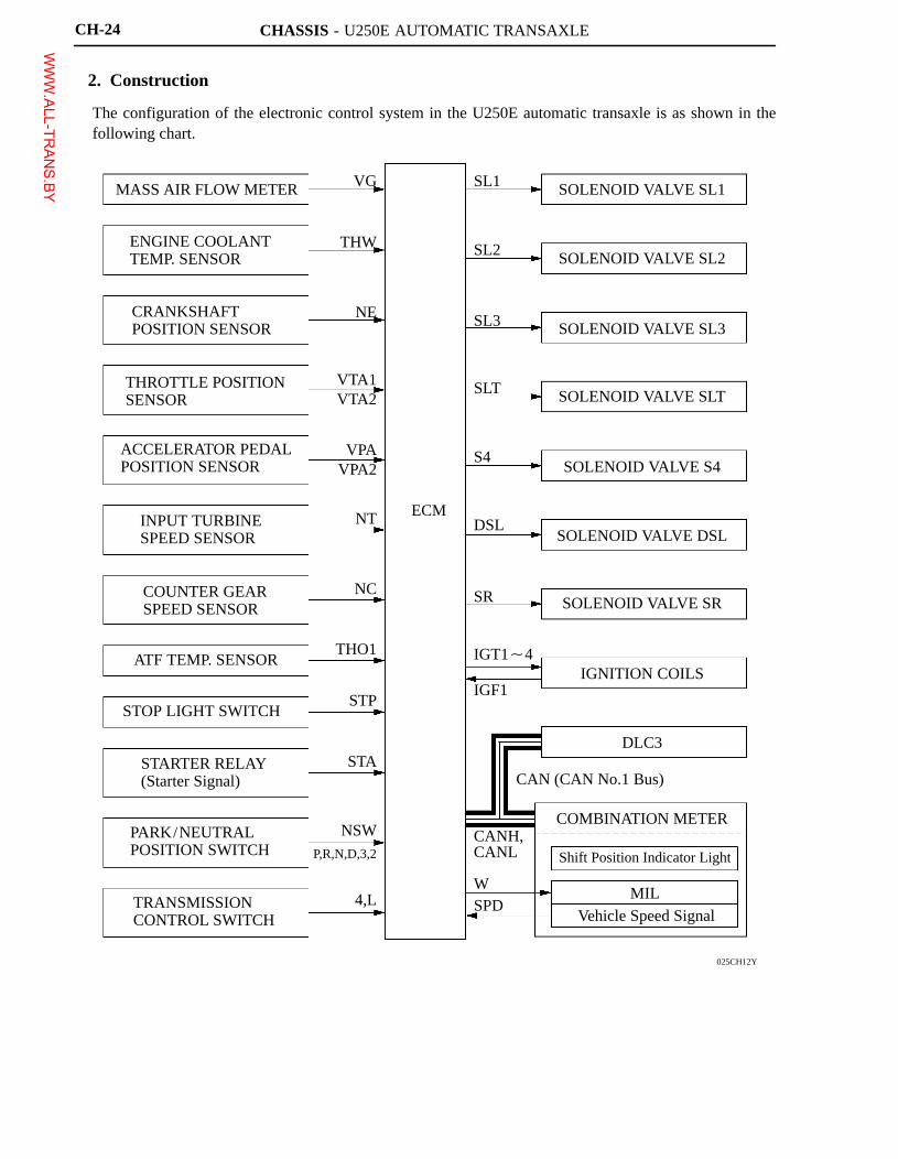
2. Construction
The configuration of the electronic control system in the U250E automatic transaxle is as shown in thefollowing chart.
WWW.ALL-TR
ANS.BY
CHASSIS - U250E AUTOMATIC TRANSAXLE
025CH13TE
Shift PositionIndicator Light
MalfunctionIndicator Lamp
Stop Light Switch
TransmissionControl Switch
DLC3
Counter GearSpeed Sensor
ECM
Input TurbineSpeed SensorPark/Neutral
Position Switch
Solenoid Valve SL3
Solenoid Valve SLT
Solenoid Valve SL1
ATF Temp. Sensor
Solenoid Valve DSL
Solenoid Valve SL2
Solenoid Valve S4
SolenoidValve SR
CH-25
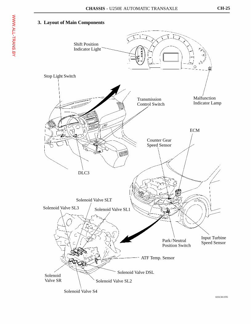
3. Layout of Main Components
WWW.ALL-TR
ANS.BY
CHASSIS - U250E AUTOMATIC TRANSAXLE
241CH87
Lower Valve Body
ATF Temperature Sensor
211CH16
Direct Clutch (C2)Drum
Input TurbineSpeed Sensor
Counter GearSpeed Sensor
Counter Drive Gear
CH-26
4. Construction and Operation of Main Components
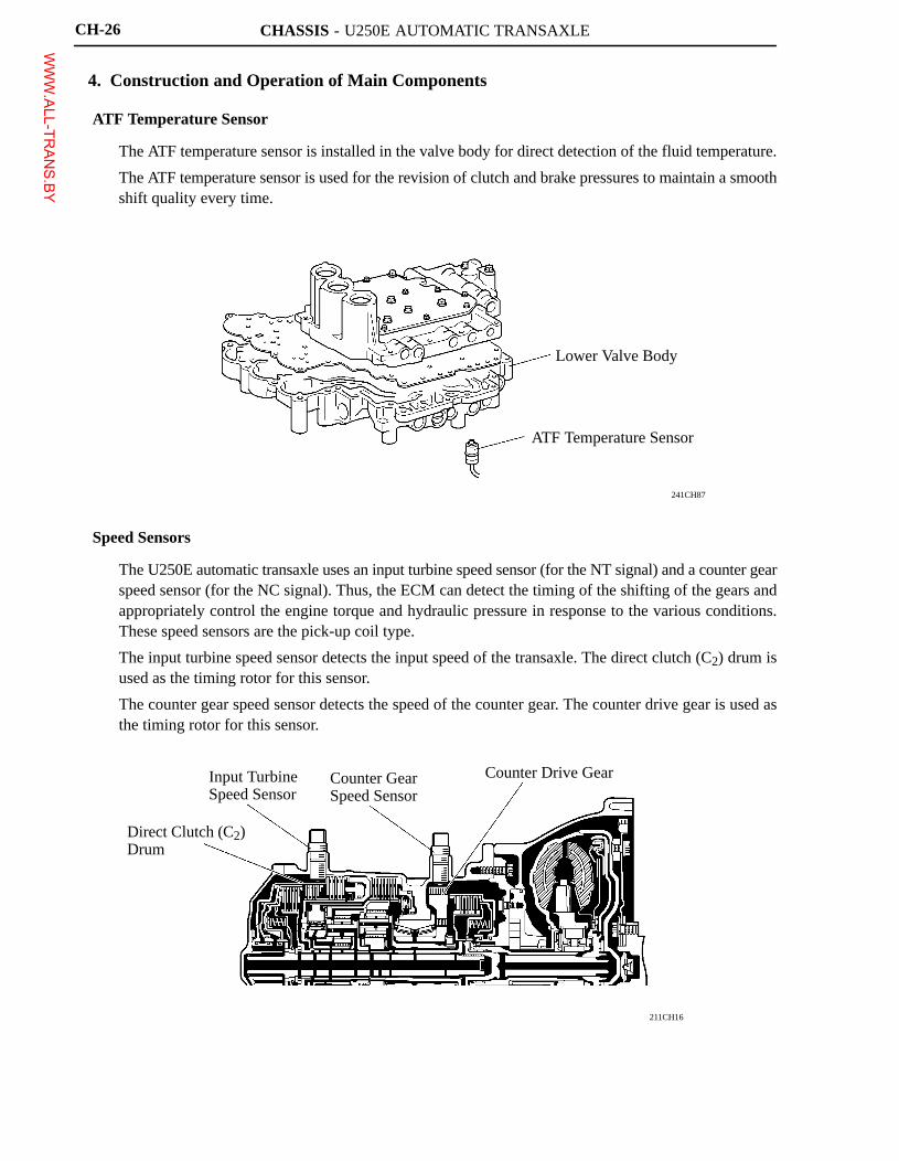
ATF Temperature Sensor
� The ATF temperature sensor is installed in the valve body for direct detection of the fluid temperature.
� The ATF temperature sensor is used for the revision of clutch and brake pressures to maintain a smoothshift quality every time.
Speed Sensors
� The U250E automatic transaxle uses an input turbine speed sensor (for the NT signal) and a counter gearspeed sensor (for the NC signal). Thus, the ECM can detect the timing of the shifting of the gears andappropriately control the engine torque and hydraulic pressure in response to the various conditions.These speed sensors are the pick-up coil type.
� The input turbine speed sensor detects the input speed of the transaxle. The direct clutch (C2) drum isused as the timing rotor for this sensor.
� The counter gear speed sensor detects the speed of the counter gear. The counter drive gear is used asthe timing rotor for this sensor.
WWW.ALL-TR
ANS.BY
CHASSIS - U250E AUTOMATIC TRANSAXLE
025CH14Y
FromIgnitionSwitch
+B
NSW
Park/NeutralPosition Switch
STA
To Starter Relay
PL P
RL R
NL N
DL D
2L 3
LL 2
NSSD
AT4
NSSL
ATL
TransmissionControl Switch
ECM
4 L
CAN(CAN No.1 Bus)
Shift PositionSignal
Combination Meter
Shift PositionIndicator Light
CH-27
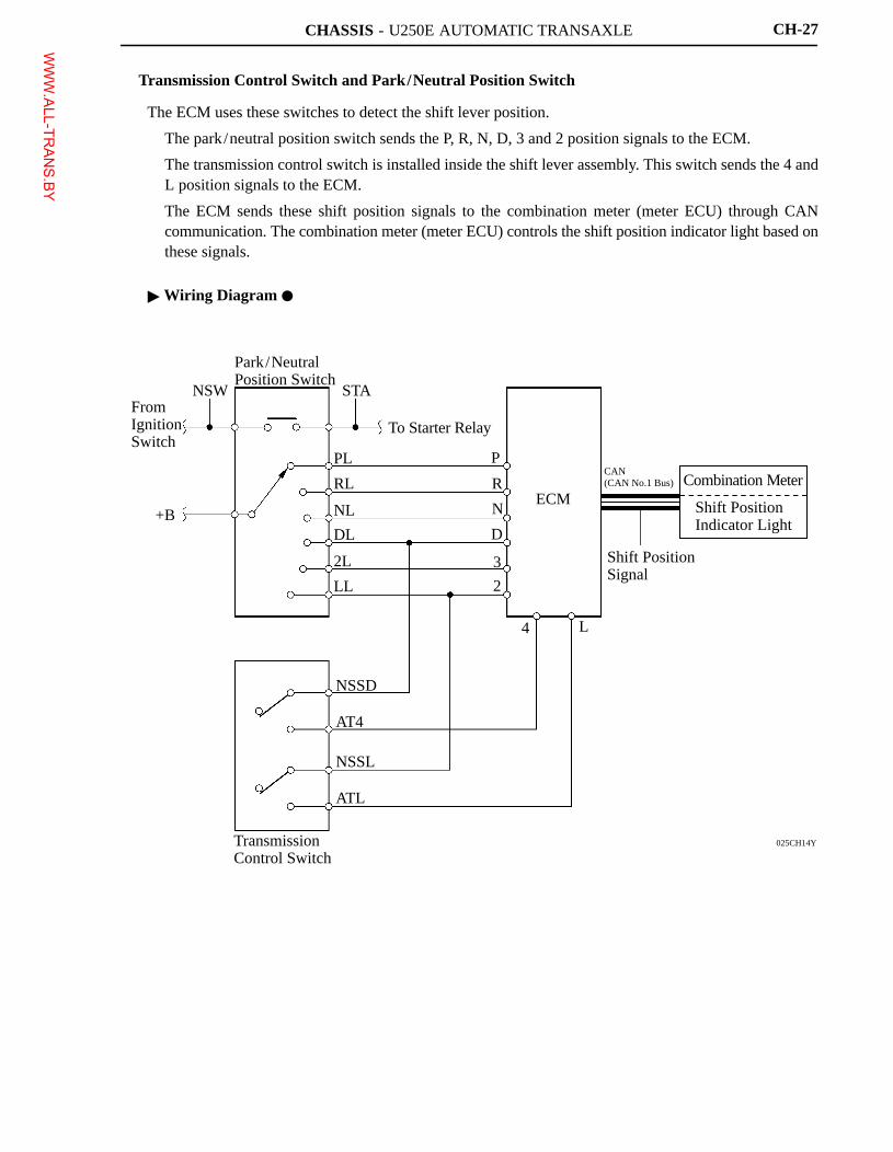
Transmission Control Switch and Park/Neutral Position Switch
The ECM uses these switches to detect the shift lever position.
� The park/neutral position switch sends the P, R, N, D, 3 and 2 position signals to the ECM.
� The transmission control switch is installed inside the shift lever assembly. This switch sends the 4 andL position signals to the ECM.
� The ECM sends these shift position signals to the combination meter (meter ECU) through CANcommunication. The combination meter (meter ECU) controls the shift position indicator light based onthese signals.
� Wiring Diagram �
WWW.ALL-TR
ANS.BY
CHASSIS - U250E AUTOMATIC TRANSAXLE
211CH15
B1 ControlValve
SL1
Line Pressure
C0 ControlValve
B1
SL2
ECM
C1 ControlValve
C0
Sensor Signal
SL3
C1
� Input Turbine Speed Sensor � Counter Gear Speed Sensor� Throttle Position Sensor� Mass Air Flow Meter� ATF Temperature Sensor� Engine Coolant Temp. Sensor
���
�: ON X: OFFB1 C0 C1
2nd3rd
X
4th�
�
�
�
�
�
XX
025CH26Y
Input ShaftSpeed
Target rpm Change Ratio
Practical rpm Change Ratio
TimeInput TurbineSpeed Sensor
ECM Signals from Various SensorsEngine Speed
Engine Torque InformationATF Temperature
SL1
SL2
SL3
Clutch /BrakePressure
Solenoid Drive Signal
Output ShaftTorque
Time
CH-28
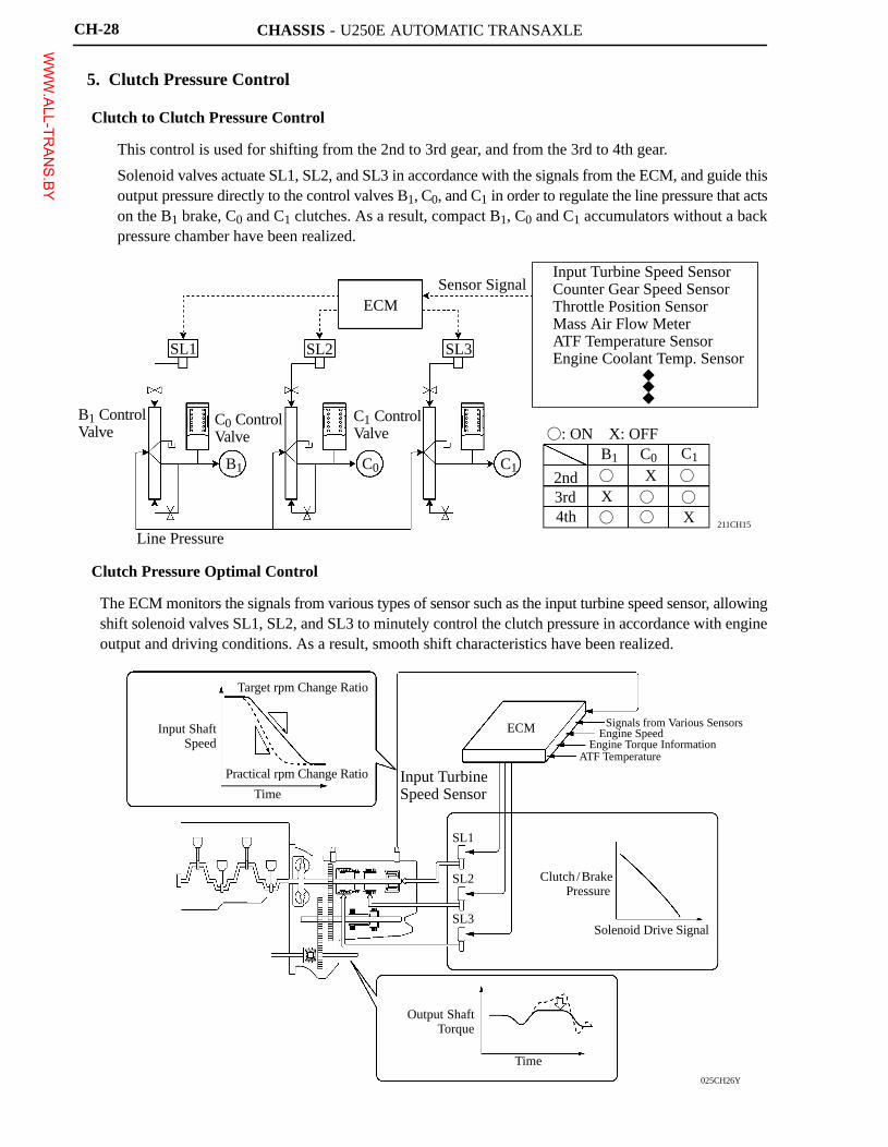
5. Clutch Pressure Control
Clutch to Clutch Pressure Control
� This control is used for shifting from the 2nd to 3rd gear, and from the 3rd to 4th gear.
� Solenoid valves actuate SL1, SL2, and SL3 in accordance with the signals from the ECM, and guide thisoutput pressure directly to the control valves B1, C0, and C1 in order to regulate the line pressure that actson the B1 brake, C0 and C1 clutches. As a result, compact B1, C0 and C1 accumulators without a backpressure chamber have been realized.
Clutch Pressure Optimal Control
The ECM monitors the signals from various types of sensor such as the input turbine speed sensor, allowingshift solenoid valves SL1, SL2, and SL3 to minutely control the clutch pressure in accordance with engineoutput and driving conditions. As a result, smooth shift characteristics have been realized.
WWW.ALL-TR
ANS.BY
CHASSIS - U250E AUTOMATIC TRANSAXLE
161ES26
Line Pressure
Pump
Primary Regulator
FluidPressure
Current
Throttle Pressure
Solenoid Valve SLT
Solenoid Drive Signal
Transaxle
Input Turbine SpeedATF Temperature
Shift Position
Engine
Throttle Valve OpeningEngine Coolant TemperatureIntake Air MassEngine Speed
ECM
CH-29
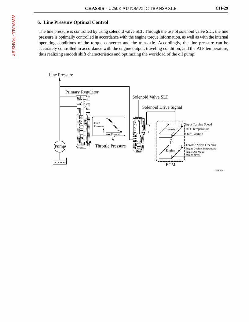
6. Line Pressure Optimal Control
The line pressure is controlled by using solenoid valve SLT. Through the use of solenoid valve SLT, the linepressure is optimally controlled in accordance with the engine torque information, as well as with the internaloperating conditions of the torque converter and the transaxle. Accordingly, the line pressure can beaccurately controlled in accordance with the engine output, traveling condition, and the ATF temperature,thus realizing smooth shift characteristics and optimizing the workload of the oil pump.
WWW.ALL-TR
ANS.BY
CHASSIS - U250E AUTOMATIC TRANSAXLE
229LC183
5th 5th4th
5th 4th 3rd
3rd 5th 4th5th
(Brake Operating)
4th 3rd 4th
Without Control
5th
With ControlBrake Operating
162CH10
Actual Acceleration < Reference Acceleration
Reference acceleration
Actual acceleration
Smaller
Uphill
Actual Acceleration > Reference Acceleration
Greater
Downhill
CH-30
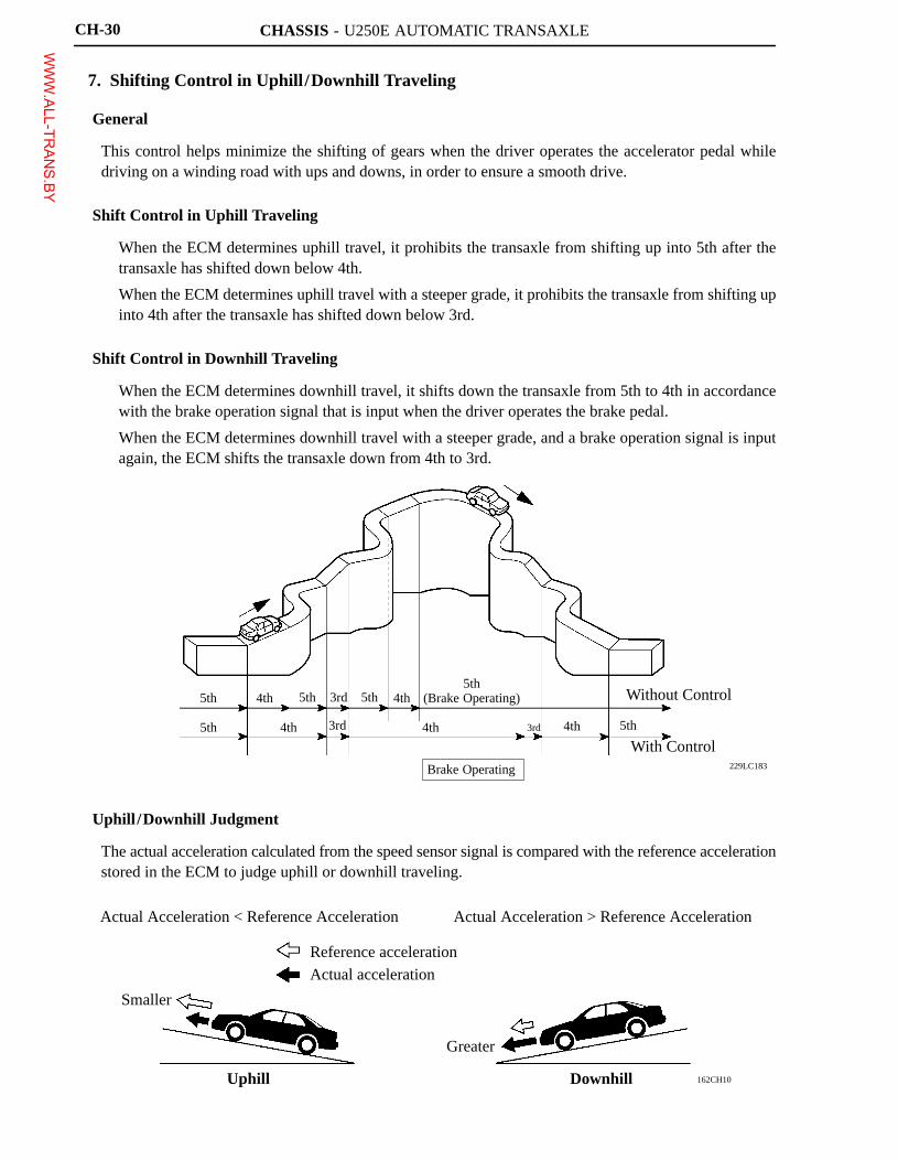
7. Shifting Control in Uphill /Downhill Traveling
General
This control helps minimize the shifting of gears when the driver operates the accelerator pedal whiledriving on a winding road with ups and downs, in order to ensure a smooth drive.
Shift Control in Uphill Traveling
� When the ECM determines uphill travel, it prohibits the transaxle from shifting up into 5th after thetransaxle has shifted down below 4th.
� When the ECM determines uphill travel with a steeper grade, it prohibits the transaxle from shifting upinto 4th after the transaxle has shifted down below 3rd.
Shift Control in Downhill Traveling
� When the ECM determines downhill travel, it shifts down the transaxle from 5th to 4th in accordancewith the brake operation signal that is input when the driver operates the brake pedal.
� When the ECM determines downhill travel with a steeper grade, and a brake operation signal is inputagain, the ECM shifts the transaxle down from 4th to 3rd.
Uphill /Downhill Judgment
The actual acceleration calculated from the speed sensor signal is compared with the reference accelerationstored in the ECM to judge uphill or downhill traveling.
WWW.ALL-TR
ANS.BY
CHASSIS - U250E AUTOMATIC TRANSAXLE
025CH25Y
EngineSpeed
Engine SpeedSignal
Input TurbineSpeed Signal
Vehicle Speed
ECM
Throttle Position Sensor
Engine CoolantTemp. Sensor
EngineSpeedSignal
Lock-upControl Valve
Input TurbineSpeed Sensor
Solenoid Valve SL2
ATF Temp. Sensor
Current
Time
LinearSolenoidSignal
275TU89
Large
ThrottleOperating
Angle Acceleration
Flex Lock-upOperating Range
Lock-up OperatingRange
Deceleration
Vehicle Speed
High
Flex Lock-up Timing
CH-31
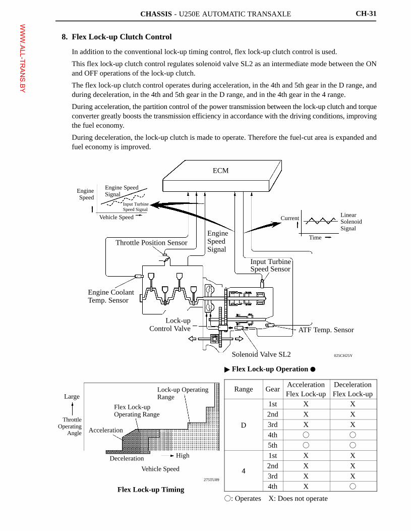
8. Flex Lock-up Clutch Control
� In addition to the conventional lock-up timing control, flex lock-up clutch control is used.
� This flex lock-up clutch control regulates solenoid valve SL2 as an intermediate mode between the ONand OFF operations of the lock-up clutch.
� The flex lock-up clutch control operates during acceleration, in the 4th and 5th gear in the D range, andduring deceleration, in the 4th and 5th gear in the D range, and in the 4th gear in the 4 range.
� During acceleration, the partition control of the power transmission between the lock-up clutch and torqueconverter greatly boosts the transmission efficiency in accordance with the driving conditions, improvingthe fuel economy.
� During deceleration, the lock-up clutch is made to operate. Therefore the fuel-cut area is expanded andfuel economy is improved.
� Flex Lock-up Operation �
Range GearAccelerationFlex Lock-up
DecelerationFlex Lock-up
1st X X
2nd X X
D 3rd X XD4th � �
5th � �
1st X X
42nd X X
43rd X X4th X �
�: Operates X: Does not operate
WWW.ALL-TR
ANS.BY
CHASSIS - U250E AUTOMATIC TRANSAXLE
Service Tip
The ECM uses the CAN protocol for diagnostic communication. Therefore, a hand-held tester anda dedicated adapter [CAN VIM (Vehicle Interface Module)] are required for accessing diagnosticdata. For details, see the 2007 Camry Repair Manual (Pub. No. RM0250U).
CH-32
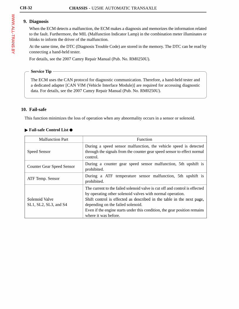
9. Diagnosis
� When the ECM detects a malfunction, the ECM makes a diagnosis and memorizes the information relatedto the fault. Furthermore, the MIL (Malfunction Indicator Lamp) in the combination meter illuminates orblinks to inform the driver of the malfunction.
� At the same time, the DTC (Diagnosis Trouble Code) are stored in the memory. The DTC can be read byconnecting a hand-held tester.
� For details, see the 2007 Camry Repair Manual (Pub. No. RM0250U).
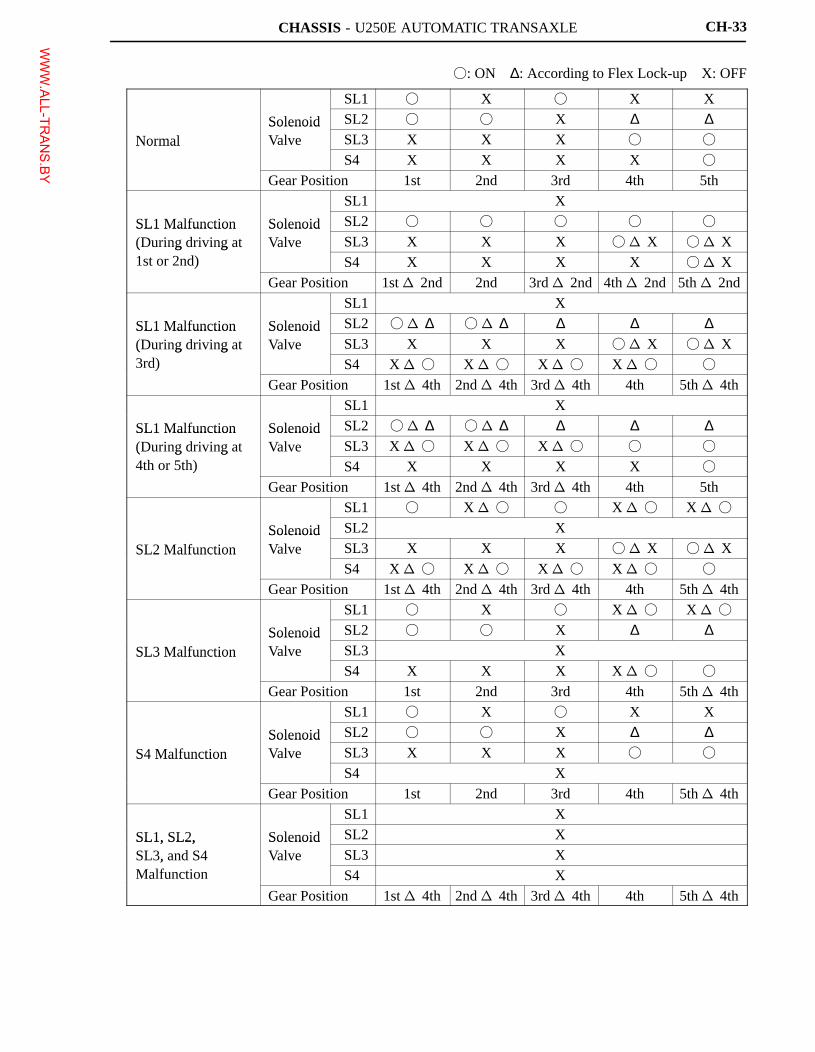
10. Fail-safe
This function minimizes the loss of operation when any abnormality occurs in a sensor or solenoid.
� Fail-safe Control List �
Malfunction Part Function
Speed SensorDuring a speed sensor malfunction, the vehicle speed is detectedthrough the signals from the counter gear speed sensor to effect normalcontrol.
Counter Gear Speed SensorDuring a counter gear speed sensor malfunction, 5th upshift isprohibited.
ATF Temp. SensorDuring a ATF temperature sensor malfunction, 5th upshift isprohibited.
Solenoid Valve
The current to the failed solenoid valve is cut off and control is effectedby operating other solenoid valves with normal operation.Shift control is effected as described in the table in the next page,Solenoid Valve
SL1, SL2, SL3, and S4Shift control is effected as described in the table in the next page,depending on the failed solenoid.Even if the engine starts under this condition, the gear position remainswhere it was before.
WWW.ALL-TR
ANS.BY
CHASSIS - U250E AUTOMATIC TRANSAXLE CH-33
�: ON ∆: According to Flex Lock-up X: OFF
SL1 � X � X X
Solenoid SL2 � � X ∆ ∆Normal
SolenoidValve SL3 X X X � �Normal
S4 X X X X �
Gear Position 1st 2nd 3rd 4th 5th
SL1 X
SL1 Malfunction Solenoid SL2 � � � � �SL1 Malfunction(During driving at
SolenoidValve SL3 X X X � � X � � X( g g
1st or 2nd) S4 X X X X � � X)
Gear Position 1st � 2nd 2nd 3rd � 2nd 4th � 2nd 5th � 2nd
SL1 X
SL1 Malfunction Solenoid SL2 � � ∆ � � ∆ ∆ ∆ ∆SL1 Malfunction(During driving at
SolenoidValve SL3 X X X � � X � � X( g g
3rd) S4 X � � X � � X � � X � � �)
Gear Position 1st � 4th 2nd � 4th 3rd � 4th 4th 5th � 4th
SL1 X
SL1 Malfunction Solenoid SL2 � � ∆ � � ∆ ∆ ∆ ∆SL1 Malfunction(During driving at
SolenoidValve SL3 X � � X � � X � � � �( g g
4th or 5th) S4 X X X X �)
Gear Position 1st � 4th 2nd � 4th 3rd � 4th 4th 5th
SL1 � X � � � X � � X � �
Solenoid SL2 X
SL2 MalfunctionSolenoidValve SL3 X X X � � X � � XSL2 Malfunction
S4 X � � X � � X � � X � � �
Gear Position 1st � 4th 2nd � 4th 3rd � 4th 4th 5th � 4th
SL1 � X � X � � X � �
Solenoid SL2 � � X ∆ ∆SL3 Malfunction
SolenoidValve SL3 XSL3 Malfunction
S4 X X X X � � �
Gear Position 1st 2nd 3rd 4th 5th � 4th
SL1 � X � X X
Solenoid SL2 � � X ∆ ∆S4 Malfunction
SolenoidValve SL3 X X X � �S4 Malfunction
S4 X
Gear Position 1st 2nd 3rd 4th 5th � 4th
SL1 X
SL1, SL2, Solenoid SL2 XSL1, SL2,SL3, and S4
SolenoidValve SL3 X,
Malfunction S4 X
Gear Position 1st � 4th 2nd � 4th 3rd � 4th 4th 5th � 4th
WWW.ALL-TR
ANS.BY
CHASSIS - U250E AUTOMATIC TRANSAXLE
212CH01
C0 C2
B1 F1 B2
Pinion Gear
Front Planetary Gear Unit
Sun Gear C1
Input Shaft
Intermediate Shaft
Counter Drive GearRing GearRing GearRear Planetary
Gear Unit
Sun Gear
Counter Shaft
C3Differential Drive Pinion
Ring GearCounter Driven Gear
Pinion Gear
U/D Planetary Gear Unit
F2 B3
Sun Gear
CH-10
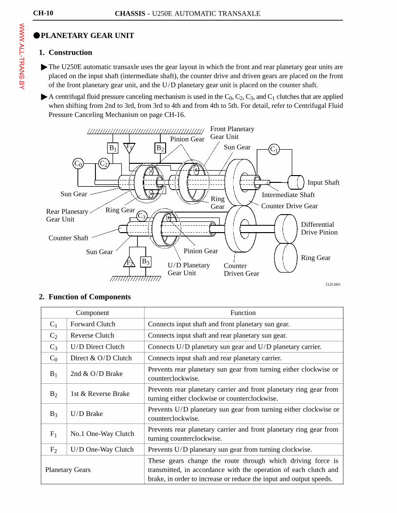
�PLANETARY GEAR UNIT
1. Construction
� The U250E automatic transaxle uses the gear layout in which the front and rear planetary gear units areplaced on the input shaft (intermediate shaft), the counter drive and driven gears are placed on the frontof the front planetary gear unit, and the U/D planetary gear unit is placed on the counter shaft.
� A centrifugal fluid pressure canceling mechanism is used in the C0, C2, C3, and C1 clutches that are appliedwhen shifting from 2nd to 3rd, from 3rd to 4th and from 4th to 5th. For detail, refer to Centrifugal FluidPressure Canceling Mechanism on page CH-16.
2. Function of Components
Component Function
C1 Forward Clutch Connects input shaft and front planetary sun gear.
C2 Reverse Clutch Connects input shaft and rear planetary sun gear.
C3 U/D Direct Clutch Connects U/D planetary sun gear and U/D planetary carrier.
C0 Direct & O/D Clutch Connects input shaft and rear planetary carrier.
B1 2nd & O/D BrakePrevents rear planetary sun gear from turning either clockwise orcounterclockwise.
B2 1st & Reverse BrakePrevents rear planetary carrier and front planetary ring gear fromturning either clockwise or counterclockwise.
B3 U/D BrakePrevents U/D planetary sun gear from turning either clockwise orcounterclockwise.
F1 No.1 One-Way ClutchPrevents rear planetary carrier and front planetary ring gear fromturning counterclockwise.
F2 U/D One-Way Clutch Prevents U/D planetary sun gear from turning clockwise.
Planetary GearsThese gears change the route through which driving force istransmitted, in accordance with the operation of each clutch andbrake, in order to increase or reduce the input and output speeds.
WWW.ALL-TR
ANS.BY
CHASSIS - U250E AUTOMATIC TRANSAXLE CH-11
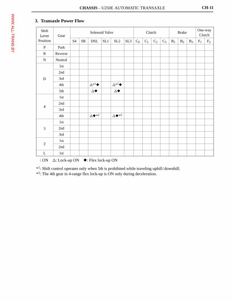
3. Transaxle Power Flow
ShiftLever Gear
Solenoid Valve Clutch BrakeOne-wayClutchLever
PositionGear
S4 SR DSL SL1 SL2 SL3 C0 C1 C2 C3 B1 B2 B3 F1 F2
P Park � � �
R Reverse � � � � �
N Neutral � � �
1st � � � � � �
2nd � � � � �
D 3rd � � � � � �
4th � �*1� �*1� � � � � �
5th � � �� �� � � � �
1st � � � � � �
42nd � � � � �
43rd � � � � � �
4th � ��*2��*2 � � � � �
1st � � � � � �
3 2nd � � � � �
3rd � � � � � �
21st � � � � � �
22nd � � � � �
L 1st � � � � � � � �
�: ON �: Lock-up ON �: Flex lock-up ON
*1: Shift control operates only when 5th is prohibited while traveling uphill /downhill.*2: The 4th gear in 4-range flex lock-up is ON only during deceleration.
WWW.ALL-TR
ANS.BY
CHASSIS - U250E AUTOMATIC TRANSAXLE
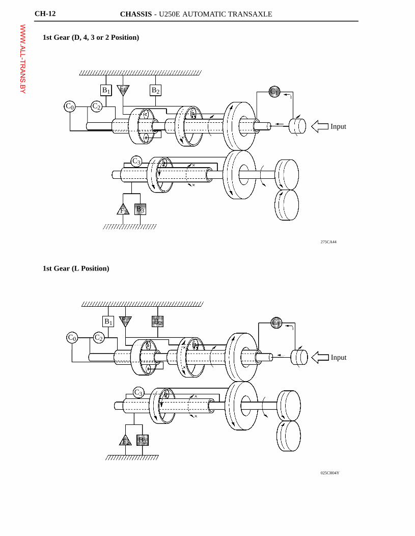
275CA44
C0 C2
B1 F1 B2 C1
Input
C3
F2 B3
025CH04Y
C0 C2
B1 F1 B2 C1
Input
C3
B3F2
CH-12
1st Gear (D, 4, 3 or 2 Position)
1st Gear (L Position)
WWW.ALL-TR
ANS.BY
CHASSIS - U250E AUTOMATIC TRANSAXLE
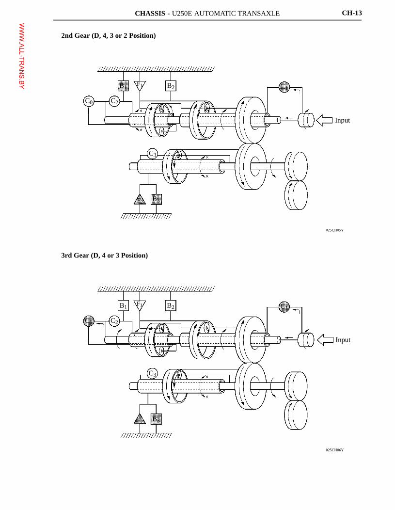
025CH05Y
C0 C2
B1F1 B2 C1
Input
C3
F2 B3
025CH06Y
C0 C2
B1F1 B2
C3
F2 B3
C1
Input
CH-13
2nd Gear (D, 4, 3 or 2 Position)
3rd Gear (D, 4 or 3 Position)
WWW.ALL-TR
ANS.BY
CHASSIS - U250E AUTOMATIC TRANSAXLE
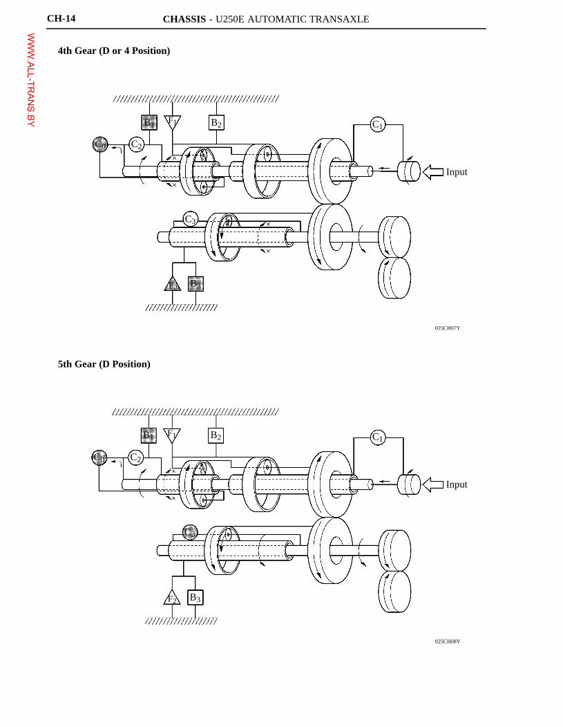
025CH07Y
C0 C2
B1 B2F1
C3
B3F2
C1
Input
025CH08Y
C0 C2
B1 F1 B2
C3
F2 B3
C1
Input
CH-14
4th Gear (D or 4 Position)
5th Gear (D Position)
WWW.ALL-TR
ANS.BY
CHASSIS - U250E AUTOMATIC TRANSAXLE
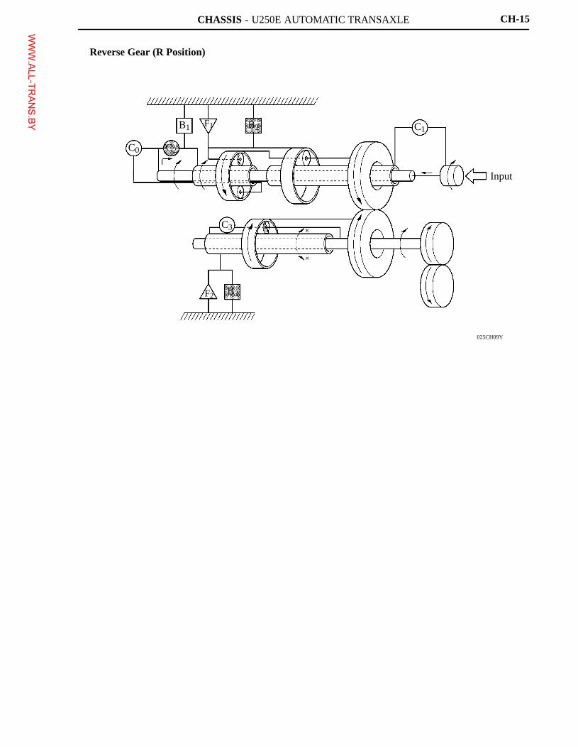
025CH09Y
C0 C2
B1 B2F1
C3
F2 B3
C1
Input
CH-15
Reverse Gear (R Position)
WWW.ALL-TR
ANS.BY
CHASSIS - U250E AUTOMATIC TRANSAXLE
275CA54
Chamber A
Piston C0 Clutch
Chamber B
C0 Clutch C2 Clutch C1 Clutch
C3 Clutch
157CH17
Centrifugal Fluid Pressure Applied to Chamber A
Target Fluid Pressure
Piston Fluid Pressure Chamber
Fluid Pressure Applied to Piston Shaft Side
Chamber B (Lubrication Fluid)
Centrifugal Fluid Pressure Applied to Chamber B
Clutch
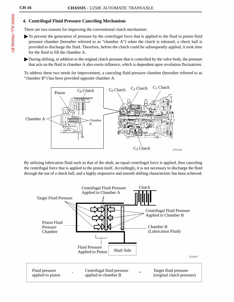
Fluid pressure applied to piston
- Centrifugal fluid pressure applied to chamber B
Target fluid pressure (original clutch pressure)
=
CH-16
4. Centrifugal Fluid Pressure Canceling Mechanism
There are two reasons for improving the conventional clutch mechanism:
� To prevent the generation of pressure by the centrifugal force that is applied to the fluid in piston fluidpressure chamber (hereafter referred to as “chamber A”) when the clutch is released, a check ball isprovided to discharge the fluid. Therefore, before the clutch could be subsequently applied, it took timefor the fluid to fill the chamber A.
� During shifting, in addition to the original clutch pressure that is controlled by the valve body, the pressurethat acts on the fluid in chamber A also exerts influence, which is dependent upon revolution fluctuations.
To address these two needs for improvement, a canceling fluid pressure chamber (hereafter referred to as“chamber B”) has been provided opposite chamber A.
By utilizing lubrication fluid such as that of the shaft, an equal centrifugal force is applied, thus cancelingthe centrifugal force that is applied to the piston itself. Accordingly, it is not necessary to discharge the fluidthrough the use of a check ball, and a highly responsive and smooth shifting characteristic has been achieved.
WWW.ALL-TR
ANS.BY
CHASSIS - U250E AUTOMATIC TRANSAXLE
025CH15TE
: The shift lever can be moved only with theignition switch in the ON position and thebrake pedal depressed.
: The shift lever can be moved at anytime.
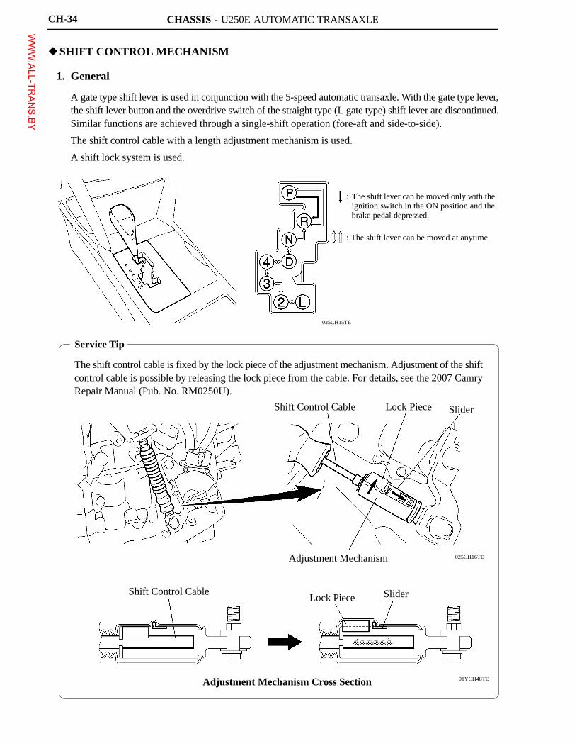
Service Tip
The shift control cable is fixed by the lock piece of the adjustment mechanism. Adjustment of the shiftcontrol cable is possible by releasing the lock piece from the cable. For details, see the 2007 CamryRepair Manual (Pub. No. RM0250U).
025CH16TE
Shift Control Cable Lock Piece Slider
01YCH48TE
Adjustment Mechanism
Shift Control CableLock Piece Slider
Adjustment Mechanism Cross Section
CH-34
�SHIFT CONTROL MECHANISM
1. General
� A gate type shift lever is used in conjunction with the 5-speed automatic transaxle. With the gate type lever,the shift lever button and the overdrive switch of the straight type (L gate type) shift lever are discontinued.Similar functions are achieved through a single-shift operation (fore-aft and side-to-side).
� The shift control cable with a length adjustment mechanism is used.
� A shift lock system is used.
WWW.ALL-TR
ANS.BY
CHASSIS - U250E AUTOMATIC TRANSAXLE
025CH20TE
Stop Light Switch
Ignition Switch
Shift LockECU
Key InterlockSolenoid
Shift Lock Solenoid Assembly
Shift LockSolenoid
P DetectionSwitch
CH-35
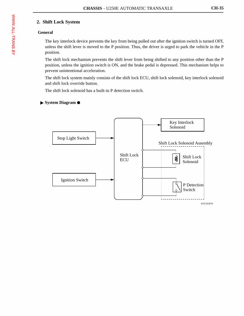
2. Shift Lock System
General
� The key interlock device prevents the key from being pulled out after the ignition switch is turned OFF,unless the shift lever is moved to the P position. Thus, the driver is urged to park the vehicle in the Pposition.
� The shift lock mechanism prevents the shift lever from being shifted to any position other than the Pposition, unless the ignition switch is ON, and the brake pedal is depressed. This mechanism helps toprevent unintentional acceleration.
� The shift lock system mainly consists of the shift lock ECU, shift lock solenoid, key interlock solenoidand shift lock override button.
� The shift lock solenoid has a built-in P detection switch.
� System Diagram �
WWW.ALL-TR
ANS.BY
CHASSIS - U250E AUTOMATIC TRANSAXLE
025CH17TE
Stop Light SwitchKey Interlock Solenoid
Shift Lock OverrideButton
Shift Lock Solenoid Assembly� Shift Lock Solenoid� P Detection Switch
Shift Lock ECU
025CH19TE
Lock Pin
Key InterlockSolenoid
CH-36
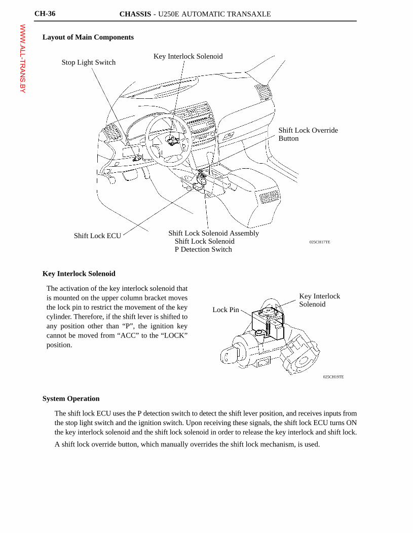
Layout of Main Components
Key Interlock Solenoid
The activation of the key interlock solenoid thatis mounted on the upper column bracket movesthe lock pin to restrict the movement of the keycylinder. Therefore, if the shift lever is shifted toany position other than “P”, the ignition keycannot be moved from “ACC” to the “LOCK”position.
System Operation
� The shift lock ECU uses the P detection switch to detect the shift lever position, and receives inputs fromthe stop light switch and the ignition switch. Upon receiving these signals, the shift lock ECU turns ONthe key interlock solenoid and the shift lock solenoid in order to release the key interlock and shift lock.
� A shift lock override button, which manually overrides the shift lock mechanism, is used.
WWW.ALL-TR
ANS.BY
CHASSIS - U250E AUTOMATIC TRANSAXLE
208CH02
Pump Impeller
Stator
Input Shaft
Lock-up Clutch
Turbine Runner
One-way Clutch
025CH03Y
Pump Body Drive Gear
Stator ShaftDriven Gear
CH-9
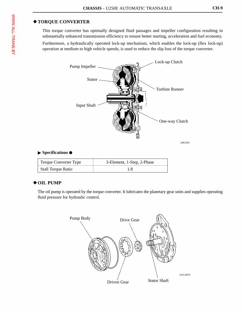
�TORQUE CONVERTER
� This torque converter has optimally designed fluid passages and impeller configuration resulting insubstantially enhanced transmission efficiency to ensure better starting, acceleration and fuel economy.
� Furthermore, a hydraulically operated lock-up mechanism, which enables the lock-up (flex lock-up)operation at medium to high vehicle speeds, is used to reduce the slip loss of the torque converter.
� Specifications �
Torque Converter Type 3-Element, 1-Step, 2-Phase
Stall Torque Ratio 1.8
�OIL PUMP
The oil pump is operated by the torque converter. It lubricates the planetary gear units and supplies operatingfluid pressure for hydraulic control.
WWW.ALL-TR
ANS.BY
CHASSIS - U250E AUTOMATIC TRANSAXLE
025CH24Y
Solenoid Valve SL3
Solenoid Valve SLT Solenoid Valve SL1
Upper Valve Body
Plate
Lower Valve Body
Solenoid Valve DSLSolenoid Valve S4
Solenoid Valve SL2
Solenoid Valve SR
025CH22Y
Solenoid Modulator Valve
Lock-up Relay Valve
Lock-up Control Valve
B1 Control Valve
Secondary Regulator ValveC1 Control Valve
Solenoid RelayValve
C0 Control Valve
Accumulator Control Valve
B3 Orifice Control Valve
B2 Control Valve
CH-17
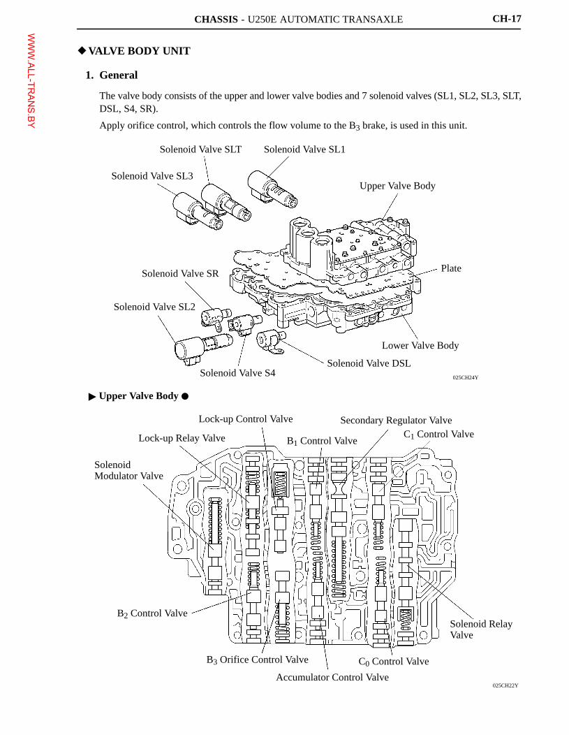
�VALVE BODY UNIT
1. General
� The valve body consists of the upper and lower valve bodies and 7 solenoid valves (SL1, SL2, SL3, SLT,DSL, S4, SR).
� Apply orifice control, which controls the flow volume to the B3 brake, is used in this unit.
� Upper Valve Body �
WWW.ALL-TR
ANS.BY
CHASSIS - U250E AUTOMATIC TRANSAXLE
025CH23Y
B2 Apply Control Valve
4-5 Shift Valve
B1 Apply Control Valve
Primary Regulator Valve
Clutch Apply Control Valve
CH-18
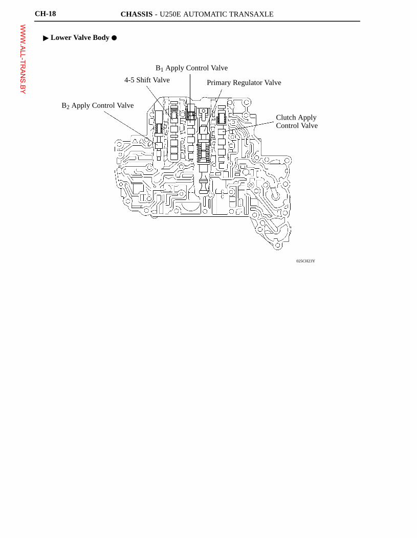
� Lower Valve Body �
WWW.ALL-TR
ANS.BY
CHASSIS - U250E AUTOMATIC TRANSAXLE
275CA51
Sleeve Solenoid Coil
Spool Valve
Hydraulic Pressure
Current
CH-19
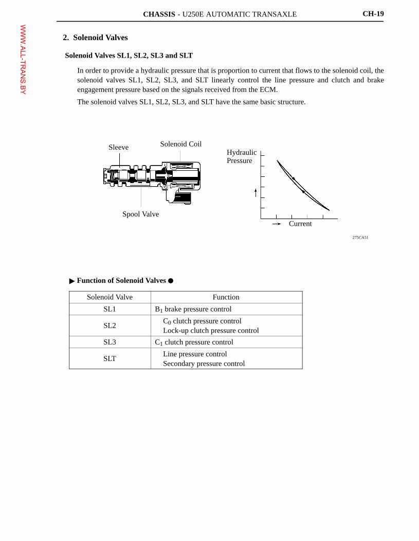
2. Solenoid Valves
Solenoid Valves SL1, SL2, SL3 and SLT
� In order to provide a hydraulic pressure that is proportion to current that flows to the solenoid coil, thesolenoid valves SL1, SL2, SL3, and SLT linearly control the line pressure and clutch and brakeengagement pressure based on the signals received from the ECM.
� The solenoid valves SL1, SL2, SL3, and SLT have the same basic structure.
� Function of Solenoid Valves �
Solenoid Valve Function
SL1 B1 brake pressure control
SL2� C0 clutch pressure control� Lock-up clutch pressure control
SL3 C1 clutch pressure control
SLT� Line pressure control� Secondary pressure control
WWW.ALL-TR
ANS.BY
CHASSIS - U250E AUTOMATIC TRANSAXLE
025CH11Y
Control Pressure
Line Pressure
Solenoid Valve ON Solenoid Valve OFF
Drain
241CH81
Solenoid Valve DSL
Line Pressure
Line Pressure
Line Pressure
Solenoid Valve S4
Solenoid Valve SR
Solenoid Relay Valve
To Lock-up Relay Valve
To B2 Control Valve
To Clutch Apply Control Valve
To 4-5 Shift Valve
ON State OFF State
CH-20
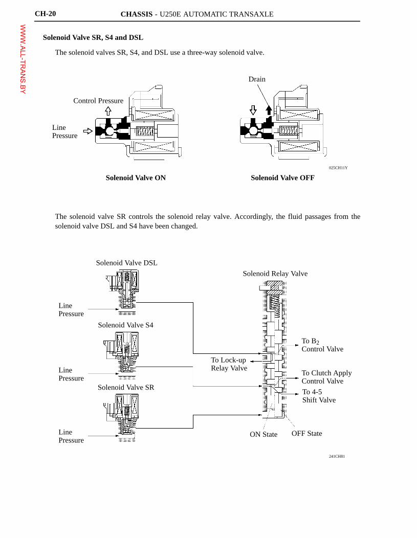
Solenoid Valve SR, S4 and DSL
� The solenoid valves SR, S4, and DSL use a three-way solenoid valve.
� The solenoid valve SR controls the solenoid relay valve. Accordingly, the fluid passages from thesolenoid valve DSL and S4 have been changed.
WWW.ALL-TR
ANS.BY
CHASSIS - U250E AUTOMATIC TRANSAXLE
243CH20
Line Pressure
4-5 Shift ValveC3 Accumulator
S4 ON
5th: C3 Clutch ON
C3
S4 OFFB3
Except 5th: B3 Brake ON
B3 Accumulator
ON State
OFF State
Solenoid Valve S4
241CH83
LinePressure
Solenoid Valve DSL
Solenoid Relay Valve
Lock-up Relay Valve
LinePressure
(a) (b)
Lock-up ON Chamber
Lock-up OFF Chamber
B2
B2 Control Valve
(b)
“R”“L”
(a)
(a) (b)
CH-21
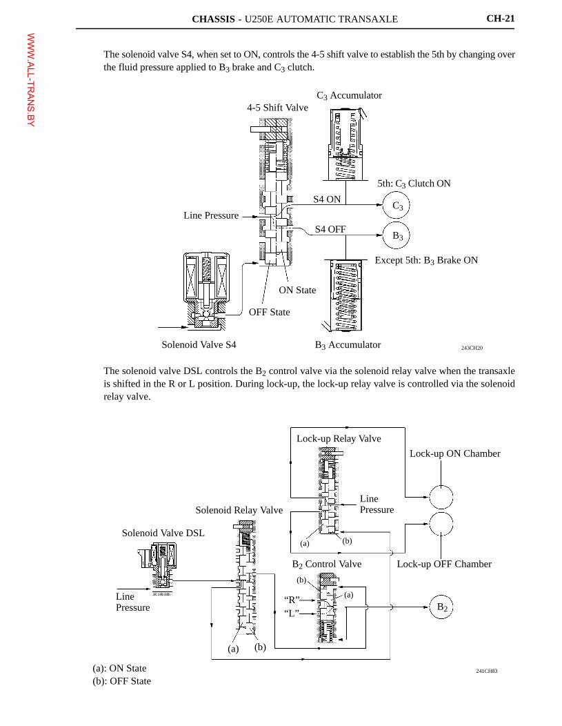
� The solenoid valve S4, when set to ON, controls the 4-5 shift valve to establish the 5th by changing overthe fluid pressure applied to B3 brake and C3 clutch.
� The solenoid valve DSL controls the B2 control valve via the solenoid relay valve when the transaxleis shifted in the R or L position. During lock-up, the lock-up relay valve is controlled via the solenoidrelay valve.
(a): ON State(b): OFF State
WWW.ALL-TR
ANS.BY
CHASSIS - U250E AUTOMATIC TRANSAXLE
241CH84
Line Pressure
B3 ApplyFluid Pressure
Orifice
B3 Orifice Control Valve
OrificeExcept 5th: B3 Brake ON
B3
B3 Accumulator
CH-22
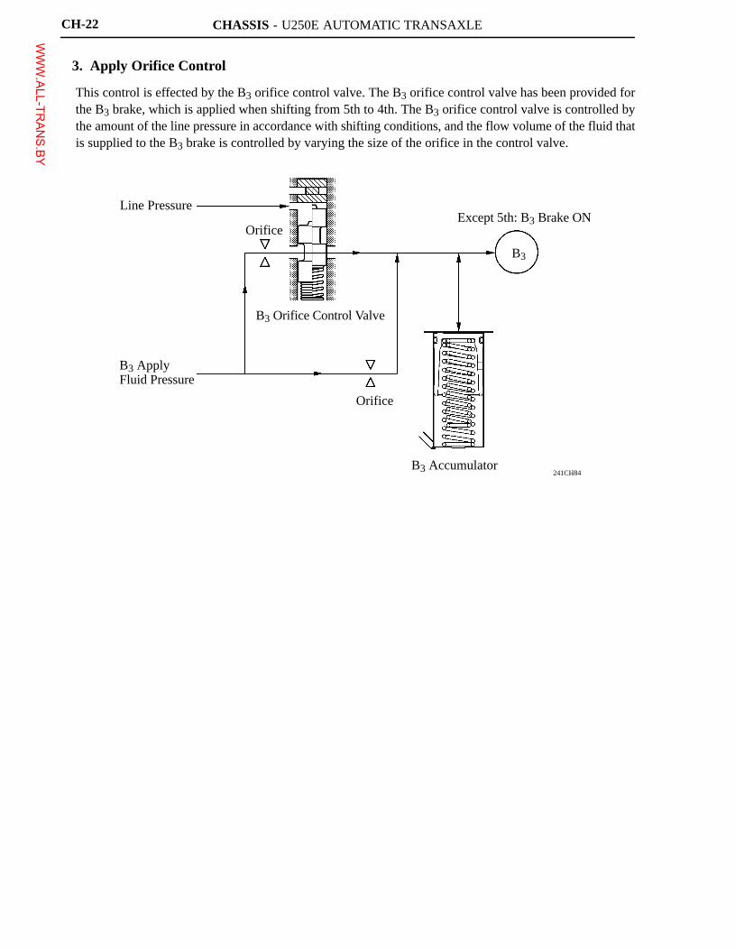
3. Apply Orifice Control
This control is effected by the B3 orifice control valve. The B3 orifice control valve has been provided forthe B3 brake, which is applied when shifting from 5th to 4th. The B3 orifice control valve is controlled bythe amount of the line pressure in accordance with shifting conditions, and the flow volume of the fluid thatis supplied to the B3 brake is controlled by varying the size of the orifice in the control valve.
WWW.ALL-TR
ANS.BY
CHASSIS - U660E AUTOMATIC TRANSAXLE
01YCH05Y
Lock-up Clutch
Lock-up Damper
One-way Clutch
Turbine Runner
Pump Impeller
Stator
Input Shaft
One-way Clutch
Narrowed
for U660E (’07 Camry)
Length Reduction
for U151E (’06 Camry)
01YCH36TE
Pump BodyDrive Gear
Driven GearPump Cover
Stator Shaft
CH-41
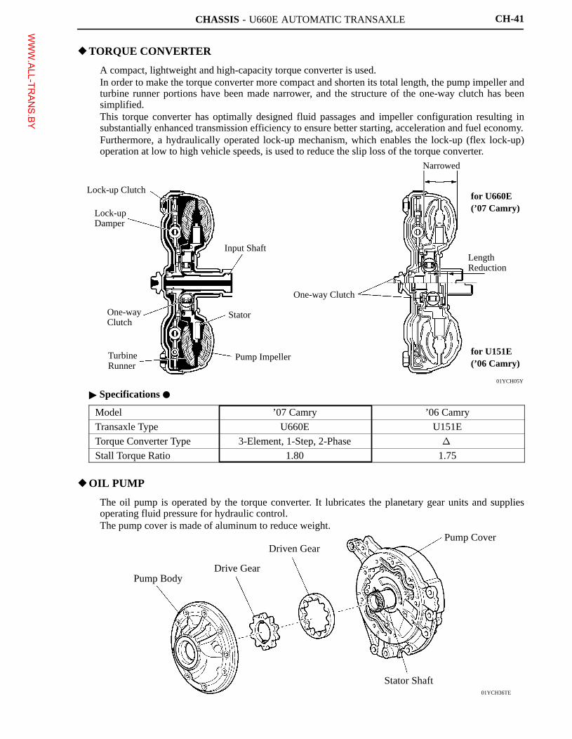
�TORQUE CONVERTER
� A compact, lightweight and high-capacity torque converter is used.� In order to make the torque converter more compact and shorten its total length, the pump impeller and
turbine runner portions have been made narrower, and the structure of the one-way clutch has beensimplified.
� This torque converter has optimally designed fluid passages and impeller configuration resulting insubstantially enhanced transmission efficiency to ensure better starting, acceleration and fuel economy.
� Furthermore, a hydraulically operated lock-up mechanism, which enables the lock-up (flex lock-up)operation at low to high vehicle speeds, is used to reduce the slip loss of the torque converter.
� Specifications �
Model ’07 Camry ’06 Camry
Transaxle Type U660E U151E
Torque Converter Type 3-Element, 1-Step, 2-Phase �
Stall Torque Ratio 1.80 1.75
�OIL PUMP
� The oil pump is operated by the torque converter. It lubricates the planetary gear units and suppliesoperating fluid pressure for hydraulic control.
� The pump cover is made of aluminum to reduce weight.
WWW.ALL-TR
ANS.BY
CHASSIS - U660E AUTOMATIC TRANSAXLE
259LSK03
Viscosity
High
Reduced Viscosity
High Temperature
: ATF Type T-IV: ATF WS
CH-40
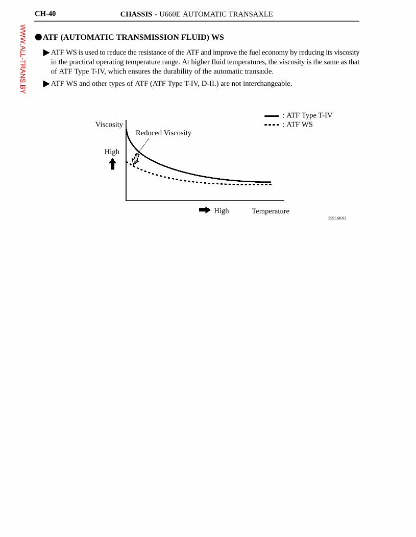
�ATF (AUTOMATIC TRANSMISSION FLUID) WS
� ATF WS is used to reduce the resistance of the ATF and improve the fuel economy by reducing its viscosityin the practical operating temperature range. At higher fluid temperatures, the viscosity is the same as thatof ATF Type T-IV, which ensures the durability of the automatic transaxle.
� ATF WS and other types of ATF (ATF Type T-IV, D-II.) are not interchangeable.
WWW.ALL-TR
ANS.BY
CHASSIS - U660E AUTOMATIC TRANSAXLE
01YCH01Y
CH-37
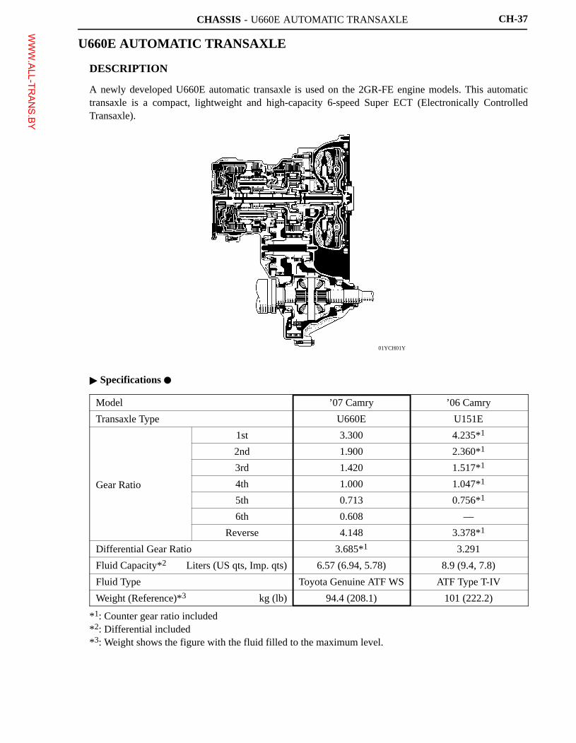
U660E AUTOMATIC TRANSAXLE
�DESCRIPTION
A newly developed U660E automatic transaxle is used on the 2GR-FE engine models. This automatictransaxle is a compact, lightweight and high-capacity 6-speed Super ECT (Electronically ControlledTransaxle).
� Specifications �
Model ’07 Camry ’06 Camry
Transaxle Type U660E U151E
1st 3.300 4.235*1
2nd 1.900 2.360*1
3rd 1.420 1.517*1
Gear Ratio 4th 1.000 1.047*1
5th 0.713 0.756*1
6th 0.608 —
Reverse 4.148 3.378*1
Differential Gear Ratio 3.685*1 3.291
Fluid Capacity*2 Liters (US qts, Imp. qts) 6.57 (6.94, 5.78) 8.9 (9.4, 7.8)
Fluid Type Toyota Genuine ATF WS ATF Type T-IV
Weight (Reference)*3 kg (lb) 94.4 (208.1) 101 (222.2)
*1: Counter gear ratio included*2: Differential included*3: Weight shows the figure with the fluid filled to the maximum level.
WWW.ALL-TR
ANS.BY
CHASSIS - U660E AUTOMATIC TRANSAXLE
01YCH02Y
C1
C2 F1 B2
Counter Drive GearB3
B1
U/D PlanetaryGear Unit
Input Shaft
DifferentialDrive Pinion
Counter Driven Gear
Ravigneaux PlanetaryGear Unit
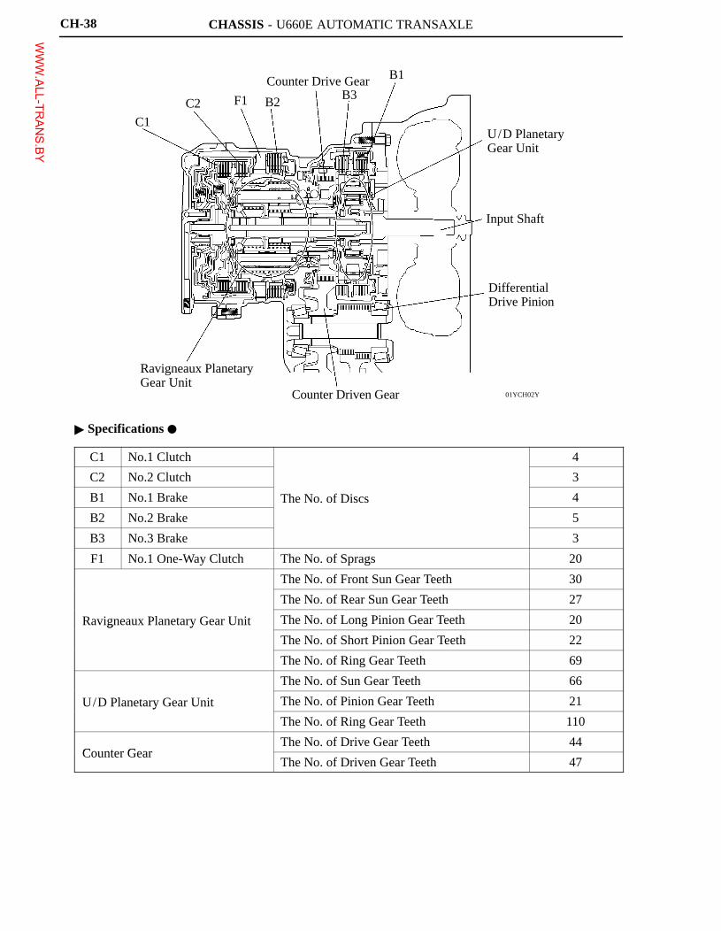
CH-38
� Specifications �
C1 No.1 Clutch 4
C2 No.2 Clutch 3
B1 No.1 Brake The No. of Discs 4
B2 No.2 Brake 5
B3 No.3 Brake 3
F1 No.1 One-Way Clutch The No. of Sprags 20
The No. of Front Sun Gear Teeth 30
The No. of Rear Sun Gear Teeth 27
Ravigneaux Planetary Gear Unit The No. of Long Pinion Gear Teeth 20g y
The No. of Short Pinion Gear Teeth 22
The No. of Ring Gear Teeth 69
The No. of Sun Gear Teeth 66
U/D Planetary Gear Unit The No. of Pinion Gear Teeth 21y
The No. of Ring Gear Teeth 110
Counter GearThe No. of Drive Gear Teeth 44
Counter GearThe No. of Driven Gear Teeth 47
WWW.ALL-TR
ANS.BY
CHASSIS - U660E AUTOMATIC TRANSAXLECH-58
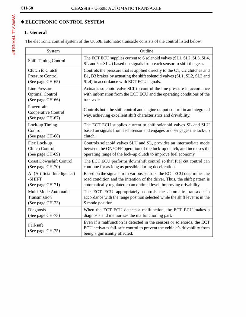
�ELECTRONIC CONTROL SYSTEM
1. General
The electronic control system of the U660E automatic transaxle consists of the control listed below.
System Outline
Shift Timing ControlThe ECT ECU supplies current to 6 solenoid valves (SL1, SL2, SL3, SL4,SL and/or SLU) based on signals from each sensor to shift the gear.
Clutch to ClutchPressure Control(See page CH-65)
Controls the pressure that is applied directly to the C1, C2 clutches andB1, B3 brakes by actuating the shift solenoid valves (SL1, SL2, SL3 andSL4) in accordance with ECT ECU signals.
Line PressureOptimal Control(See page CH-66)
Actuates solenoid valve SLT to control the line pressure in accordancewith information from the ECT ECU and the operating conditions of thetransaxle.
PowertrainCooperative Control(See page CH-67)
Controls both the shift control and engine output control in an integratedway, achieving excellent shift characteristics and drivability.
Lock-up TimingControl(See page CH-68)
The ECT ECU supplies current to shift solenoid valves SL and SLUbased on signals from each sensor and engages or disengages the lock-upclutch.
Flex Lock-upClutch Control(See page CH-69)
Controls solenoid valves SLU and SL, provides an intermediate modebetween the ON/OFF operation of the lock-up clutch, and increases theoperating range of the lock-up clutch to improve fuel economy.
Coast Downshift Control(See page CH-70)
The ECT ECU performs downshift control so that fuel cut control cancontinue for as long as possible during deceleration.
AI (Artificial Intelligence)-SHIFT(See page CH-71)
Based on the signals from various sensors, the ECT ECU determines theroad condition and the intention of the driver. Thus, the shift pattern isautomatically regulated to an optimal level, improving drivability.
Multi-Mode AutomaticTransmission(See page CH-73)
The ECT ECU appropriately controls the automatic transaxle inaccordance with the range position selected while the shift lever is in theS mode position.
Diagnosis(See page CH-75)
When the ECT ECU detects a malfunction, the ECT ECU makes adiagnosis and memorizes the malfunctioning part.
Fail-safe(See page CH-75)
Even if a malfunction is detected in the sensors or solenoids, the ECTECU activates fail-safe control to prevent the vehicle’s drivability frombeing significantly affected.
WWW.ALL-TR
ANS.BY
CHASSIS - U660E AUTOMATIC TRANSAXLE
01YCH23Y
INPUT TURBINESPEED SENSOR
COUNTER GEAR SPEED SENSOR
ATF PRESSURE SWITCHES
ATF TEMP. SENSOR
STOP LIGHT SWITCH
COMBINATION METER
STARTER RELAY(Starter Signal)
PARK/NEUTRAL POSITION SWITCH
TRANSMISSION CONTROL SWITCH
MASS AIR FLOW METER
ENGINE COOLANT TEMP. SENSOR
CRANKSHAFT POSITION SENSOR
THROTTLE POSITION SENSOR
ACCELERATOR PEDAL POSITION SENSOR
NTB
NCB
TPS1,2,3
NTO
NCO
THO1
STP
SPD
STA
NSW
R,D
NSW
P,R,N,D
S,SFTU
SFTD
VG
THW
NE
VTA1
VTA2
VPA
VPA2
CAN+ CAN-
CAN+ CAN-
SL1
SL2
SL3
SL4
SLU
SLT
SL
W
CANHCANL
#10�#60
IGT1�6
IGF
M
Local CAN
CAN (CAN No.1 Bus)
SOLENOID VALVE SL1
SOLENOID VALVE SL2
SOLENOID VALVE SL3
SOLENOID VALVE SL4
SOLENOID VALVE SLU
SOLENOID VALVE SLT
SOLENOID VALVE SL
DLC3
COMBINATION METER
Shift Range Indicator Light
Shift Position Indicator Light
S Mode Indicator Light
BuzzerMIL
FUEL INJECTORS
IGNITION COILS
THROTTLE CONTROL MOTOR
ECT ECU
ECM
CH-59
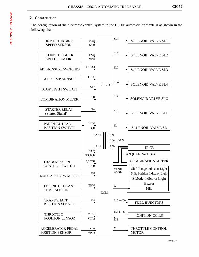
2. Construction
The configuration of the electronic control system in the U660E automatic transaxle is as shown in thefollowing chart.
WWW.ALL-TR
ANS.BY
CHASSIS - U660E AUTOMATIC TRANSAXLE
025CH10TE
S mode Indicator Light
Shift Position Indicator Light
Shift Range Indicator Light Malfunction
Indicator Lamp
Stop Light Switch
DLC3
Transmission Control Switch
ECM
ECT ECU
ATF Temp. Sensor
ATF Pressure Switch
Counter GearSpeed Sensor
Input Turbine Speed Sensor
Park/Neutral Position Switch
Solenoid Valve SL
Solenoid Valve SLT
Solenoid Valve SLU
Solenoid Valve SL2Solenoid Valve SL1Solenoid Valve
SL4Solenoid Valve SL3
CH-60
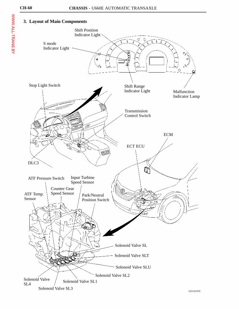
3. Layout of Main Components
WWW.ALL-TR
ANS.BY
CHASSIS - U660E AUTOMATIC TRANSAXLE
025CH28TE
ECT ECU
Transaxle Connector
Automatic TransaxleCompensation Value
QR Code
Transaxle Front View
CH-61
4. Construction and Operation of Main Components
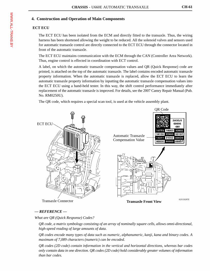
ECT ECU
� The ECT ECU has been isolated from the ECM and directly fitted to the transaxle. Thus, the wiringharness has been shortened allowing the weight to be reduced. All the solenoid valves and sensors usedfor automatic transaxle control are directly connected to the ECT ECU through the connector located infront of the automatic transaxle.
� The ECT ECU maintains communication with the ECM through the CAN (Controller Area Network).Thus, engine control is effected in coordination with ECT control.
� A label, on which the automatic transaxle compensation values and QR (Quick Response) code areprinted, is attached on the top of the automatic transaxle. The label contains encoded automatic transaxleproperty information. When the automatic transaxle is replaced, allow the ECT ECU to learn theautomatic transaxle property information by inputting the automatic transaxle compensation values intothe ECT ECU using a hand-held tester. In this way, the shift control performance immediately afterreplacement of the automatic transaxle is improved. For details, see the 2007 Camry Repair Manual (Pub.No. RM0250U).
� The QR code, which requires a special scan tool, is used at the vehicle assembly plant.
— REFERENCE —
What are QR (Quick Response) Codes?
� QR code, a matrix symbology consisting of an array of nominally square cells, allows omni-directional,high-speed reading of large amounts of data.
� QR codes encode many types of data such as numeric, alphanumeric, kanji, kana and binary codes. Amaximum of 7,089 characters (numeric) can be encoded.
� QR codes (2D code) contain information in the vertical and horizontal directions, whereas bar codesonly contain data in one direction. QR codes (2D code) hold considerably greater volumes of informationthan bar codes.
WWW.ALL-TR
ANS.BY
CHASSIS - U660E AUTOMATIC TRANSAXLE
01YCH44TELower Valve Body
ATF TemperatureSensor
01YCH45TE
ATF Pressure Switch
Lower Valve Body
ATF PressureSwitch
ATF Pressure SwitchCross-Section
CH-62
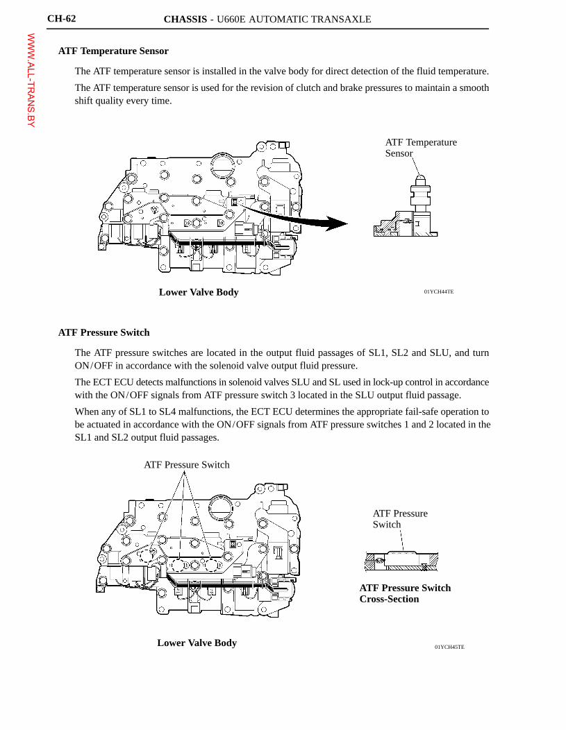
ATF Temperature Sensor
� The ATF temperature sensor is installed in the valve body for direct detection of the fluid temperature.
� The ATF temperature sensor is used for the revision of clutch and brake pressures to maintain a smoothshift quality every time.
ATF Pressure Switch
� The ATF pressure switches are located in the output fluid passages of SL1, SL2 and SLU, and turnON/OFF in accordance with the solenoid valve output fluid pressure.
� The ECT ECU detects malfunctions in solenoid valves SLU and SL used in lock-up control in accordancewith the ON/OFF signals from ATF pressure switch 3 located in the SLU output fluid passage.
� When any of SL1 to SL4 malfunctions, the ECT ECU determines the appropriate fail-safe operation tobe actuated in accordance with the ON/OFF signals from ATF pressure switches 1 and 2 located in theSL1 and SL2 output fluid passages.
WWW.ALL-TR
ANS.BY
CHASSIS - U660E AUTOMATIC TRANSAXLE
01YCH24TE
No.2 Upper Valve Body
Input TurbineSpeed Sensor
Counter GearSpeed Sensor
No.1 Upper Valve Body
Engine Side
Lower Valve Body
CH-63
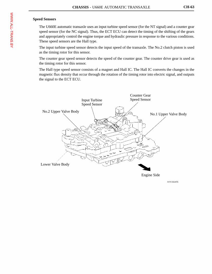
Speed Sensors
� The U660E automatic transaxle uses an input turbine speed sensor (for the NT signal) and a counter gearspeed sensor (for the NC signal). Thus, the ECT ECU can detect the timing of the shifting of the gearsand appropriately control the engine torque and hydraulic pressure in response to the various conditions.These speed sensors are the Hall type.
� The input turbine speed sensor detects the input speed of the transaxle. The No.2 clutch piston is usedas the timing rotor for this sensor.
� The counter gear speed sensor detects the speed of the counter gear. The counter drive gear is used asthe timing rotor for this sensor.
� The Hall type speed sensor consists of a magnet and Hall IC. The Hall IC converts the changes in themagnetic flux density that occur through the rotation of the timing rotor into electric signal, and outputsthe signal to the ECT ECU.
WWW.ALL-TR
ANS.BY
CHASSIS - U660E AUTOMATIC TRANSAXLE
Shift Position Indicator Light
01YCH25Y
FromStarter Cut Relay*1Ignition Switch*2
IG1Relay
Park/NeutralPosition Switch
IG1Relay
TransmissionControl Switch
NSW
B
RB
IG
STA
L
DL
NL
RL
PL
S
SFTU
SFTD
To Starter Relay
S
SFTU
SFTD
P R N D
ECM
Shift PositionSignal
LocalCAN
R D
ECT ECU
Shift PositionSignal
CAN(CAN No.1 Bus)
Combination Meter
S Mode Indicator Light
Shift Range Indicator Light
CH-64
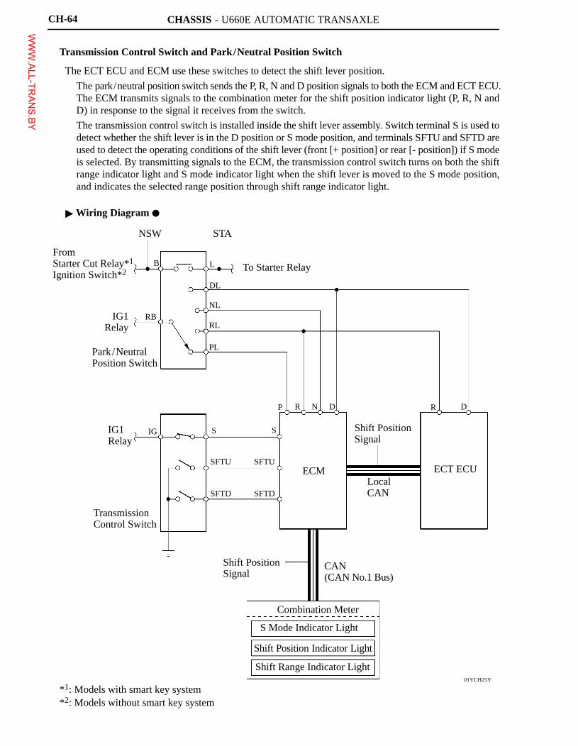
Transmission Control Switch and Park/Neutral Position Switch
The ECT ECU and ECM use these switches to detect the shift lever position.
� The park/neutral position switch sends the P, R, N and D position signals to both the ECM and ECT ECU.The ECM transmits signals to the combination meter for the shift position indicator light (P, R, N andD) in response to the signal it receives from the switch.
� The transmission control switch is installed inside the shift lever assembly. Switch terminal S is used todetect whether the shift lever is in the D position or S mode position, and terminals SFTU and SFTD areused to detect the operating conditions of the shift lever (front [+ position] or rear [- position]) if S modeis selected. By transmitting signals to the ECM, the transmission control switch turns on both the shiftrange indicator light and S mode indicator light when the shift lever is moved to the S mode position,and indicates the selected range position through shift range indicator light.
� Wiring Diagram �
*1: Models with smart key system*2: Models without smart key system
WWW.ALL-TR
ANS.BY
CHASSIS - U660E AUTOMATIC TRANSAXLE
01YCH26TE
ATF Temp. Sensor
Input TurbineSpeed Sensor
Counter GearSpeed Sensor
ECT ECU
Engine TorqueInformation
Local CANECM
Mass Air Flow Meter
Engine CoolantTemp. Sensor
Throttle PositionSensor
SL1
C1
SL2
C2
SL3
B1
SL4
B3
Line Pressure
CH-65
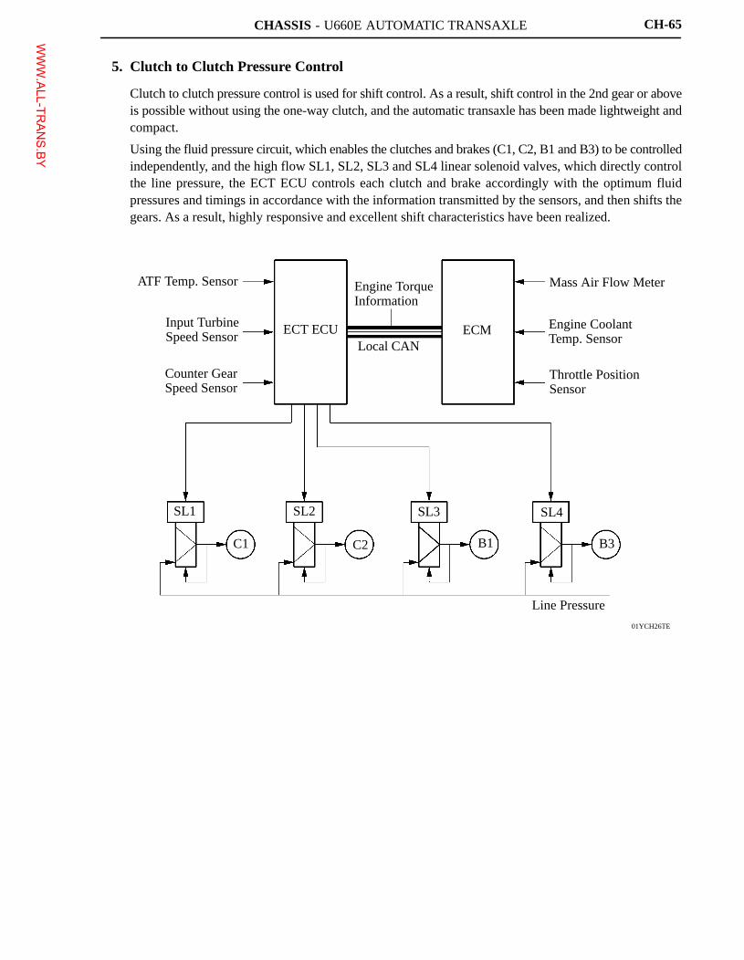
5. Clutch to Clutch Pressure Control
� Clutch to clutch pressure control is used for shift control. As a result, shift control in the 2nd gear or aboveis possible without using the one-way clutch, and the automatic transaxle has been made lightweight andcompact.
� Using the fluid pressure circuit, which enables the clutches and brakes (C1, C2, B1 and B3) to be controlledindependently, and the high flow SL1, SL2, SL3 and SL4 linear solenoid valves, which directly controlthe line pressure, the ECT ECU controls each clutch and brake accordingly with the optimum fluidpressures and timings in accordance with the information transmitted by the sensors, and then shifts thegears. As a result, highly responsive and excellent shift characteristics have been realized.
WWW.ALL-TR
ANS.BY
CHASSIS - U660E AUTOMATIC TRANSAXLE
01YCH27Y
Line Pressure
Pump
Primary Regulator
FluidPressure
Current
Solenoid Valve SLT
Solenoid Drive Signal
ECTECU
ECM
Input Turbine Speed
ATF Temp.
Shift Position
Throttle Valve Opening
Intake Air Mass
Engine Coolant Temp.Engine Speed
CH-66
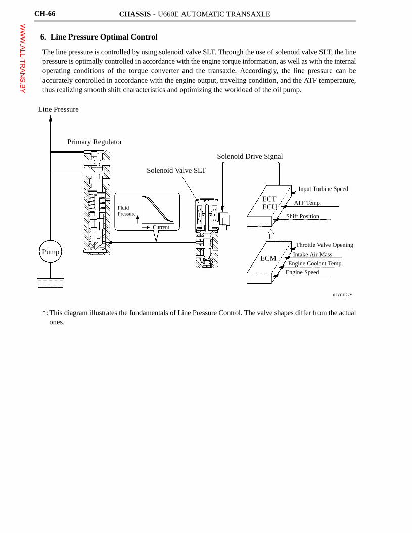
6. Line Pressure Optimal Control
The line pressure is controlled by using solenoid valve SLT. Through the use of solenoid valve SLT, the linepressure is optimally controlled in accordance with the engine torque information, as well as with the internaloperating conditions of the torque converter and the transaxle. Accordingly, the line pressure can beaccurately controlled in accordance with the engine output, traveling condition, and the ATF temperature,thus realizing smooth shift characteristics and optimizing the workload of the oil pump.
*: This diagram illustrates the fundamentals of Line Pressure Control. The valve shapes differ from the actualones.
WWW.ALL-TR
ANS.BY
CHASSIS - U660E AUTOMATIC TRANSAXLE
01YCH28Y
AcceleratorPedal Opening
ThrottleValve Opening
DriveForce
Linear Output Increase
Tire Slippage Suppression
Time
: Conventional
: U660E
01YCH29Y
Variation inAccelerator
Pedal Operation
Gear Position
Drive Force
3rd4th
5th6th
Drive Force ischanged by driver’sinput
Time
: Slow Accelerator Pedal Operation
: Sudden Accelerator Pedal Operation
CH-67
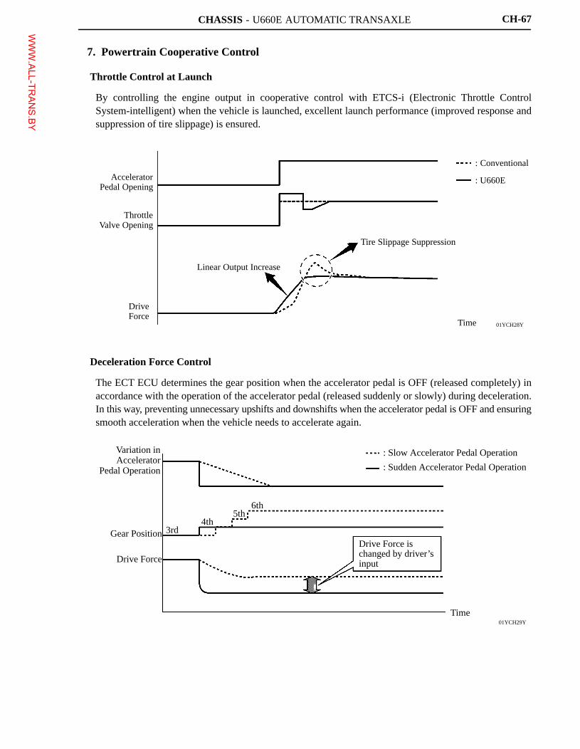
7. Powertrain Cooperative Control
Throttle Control at Launch
By controlling the engine output in cooperative control with ETCS-i (Electronic Throttle ControlSystem-intelligent) when the vehicle is launched, excellent launch performance (improved response andsuppression of tire slippage) is ensured.
Deceleration Force Control
The ECT ECU determines the gear position when the accelerator pedal is OFF (released completely) inaccordance with the operation of the accelerator pedal (released suddenly or slowly) during deceleration.In this way, preventing unnecessary upshifts and downshifts when the accelerator pedal is OFF and ensuringsmooth acceleration when the vehicle needs to accelerate again.
WWW.ALL-TR
ANS.BY
CHASSIS - U660E AUTOMATIC TRANSAXLE
01YCH30Y
Accelerator PedalOperation
Driver’s desireddrive force
ECM
ETCS-i ControlESA Control
Optimalengine output
Optimal clutchengagement hydraulicpressure and timing
ECT ECU
DrivesSolenoidValve
Solenoid Valve(SL1, SL2, SL3, SL4)
Driver’s desired driveforce is achieved
01YCH31Y
Large
ThrottleOpeningAngle
Lock-upOperating Range
Vehicle Speed
2nd 3rd
4th 5th 6th Lock-upOperating Range
High
Lock-up Timing
CH-68
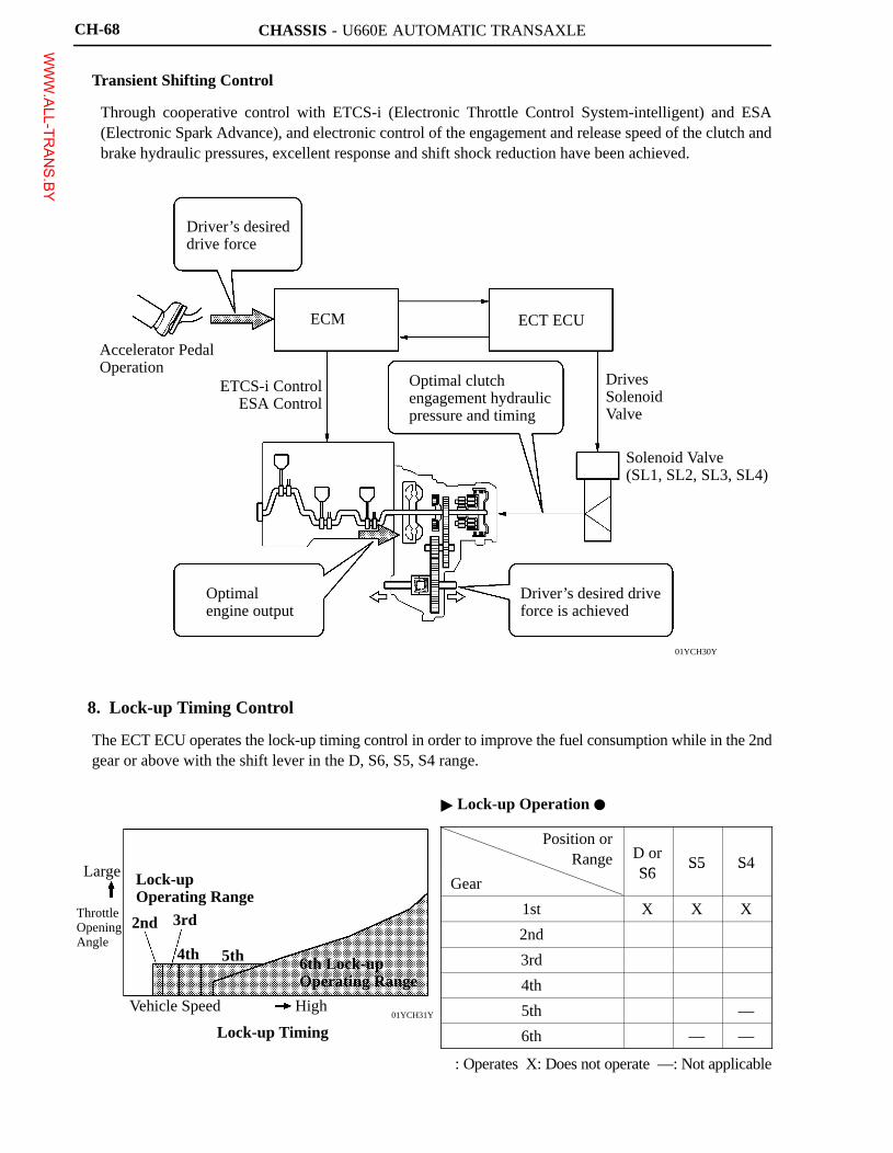
Transient Shifting Control
Through cooperative control with ETCS-i (Electronic Throttle Control System-intelligent) and ESA(Electronic Spark Advance), and electronic control of the engagement and release speed of the clutch andbrake hydraulic pressures, excellent response and shift shock reduction have been achieved.
8. Lock-up Timing Control
The ECT ECU operates the lock-up timing control in order to improve the fuel consumption while in the 2ndgear or above with the shift lever in the D, S6, S5, S4 range.
� Lock-up Operation �
Position orRange D or
S6S5 S4
GearS6
S5 S4
1st X X X
2nd � � �
3rd � � �
4th � � �
5th � � —
6th � — —
�: Operates X: Does not operate —: Not applicable
WWW.ALL-TR
ANS.BY
CHASSIS - U660E AUTOMATIC TRANSAXLE
01YCH32Y
EngineSpeed
Engine SpeedSignal
Input TurbineSpeed Signal
Vehicle Speed
ECM
Throttle Position Sensor
Engine CoolantTemp. Sensor
Lock-upControl Valve
EngineSpeedSignal
ECT ECU
Input TurbineSpeed Sensor
ATF Temperature Sensor
Solenoid Valve SLU
Current
Time
LinearSolenoidSignal
01YCH33Y
Large
ThrottleOpeningAngle
VehicleSpeed
Flex Lock-up OperatingRange (Acceleration)
High
Lock-upOperating Range
Flex Lock-up OperatingRange (Deceleration)
Flex Lock-Up Timing in 6th Gear
CH-69
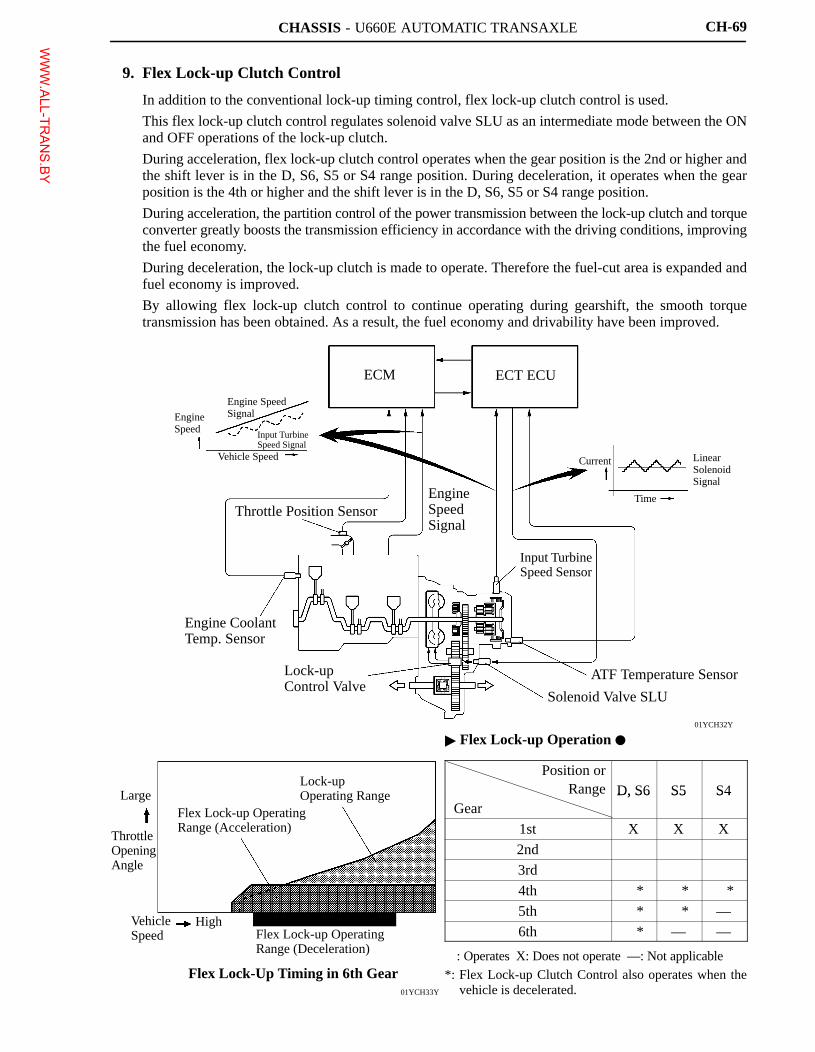
9. Flex Lock-up Clutch Control
� In addition to the conventional lock-up timing control, flex lock-up clutch control is used.
� This flex lock-up clutch control regulates solenoid valve SLU as an intermediate mode between the ONand OFF operations of the lock-up clutch.
� During acceleration, flex lock-up clutch control operates when the gear position is the 2nd or higher andthe shift lever is in the D, S6, S5 or S4 range position. During deceleration, it operates when the gearposition is the 4th or higher and the shift lever is in the D, S6, S5 or S4 range position.
� During acceleration, the partition control of the power transmission between the lock-up clutch and torqueconverter greatly boosts the transmission efficiency in accordance with the driving conditions, improvingthe fuel economy.
� During deceleration, the lock-up clutch is made to operate. Therefore the fuel-cut area is expanded andfuel economy is improved.
� By allowing flex lock-up clutch control to continue operating during gearshift, the smooth torquetransmission has been obtained. As a result, the fuel economy and drivability have been improved.
� Flex Lock-up Operation �
Position orRange D, S6 S5 S4
GearD, S6 S5 S4
1st X X X
2nd � � �
3rd � � �
4th �* �* �*
5th �* �* —
6th �* — —
�: Operates X: Does not operate —: Not applicable
*: Flex Lock-up Clutch Control also operates when thevehicle is decelerated.
WWW.ALL-TR
ANS.BY
CHASSIS - U660E AUTOMATIC TRANSAXLE
01YCH34Y
Fuel Cut Control ON
Fuel Cut Control OFF
EngineSpeed
Continuous Fuel CutControl Operation
6th
5th
to 5th to 4th
to 4th to 3rd
Time
Fuel Cut Control ON
Fuel Cut Control OFF
: with Downshift Control (6AT)
: without Downshift Control (5AT)
CH-70
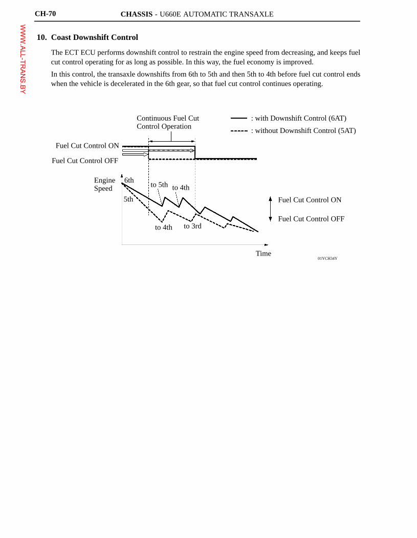
10. Coast Downshift Control
� The ECT ECU performs downshift control to restrain the engine speed from decreasing, and keeps fuelcut control operating for as long as possible. In this way, the fuel economy is improved.
� In this control, the transaxle downshifts from 6th to 5th and then 5th to 4th before fuel cut control endswhen the vehicle is decelerated in the 6th gear, so that fuel cut control continues operating.
WWW.ALL-TR
ANS.BY
CHASSIS - U660E AUTOMATIC TRANSAXLE
00MCH14Y
Input Signal
Sensor Signal
� ThrottleOpening Angle
� Vehicle Speed� Engine Speed� Brake Signal
Calculation by ECU
VehicleAcceleration
AI-SHIFT
Road ConditionUphill /Downhill Driving
Smaller Estimating the Grade
Greater
: Criterion Acceleration
: Actual Acceleration
Driver’s Intention
� AccelerationPedal Operation
� VehicleCondition
Estimating theDriver’s Intention
Basic ShiftPattern Control
Road ConditionSupport Control
Driver’s IntentionSupport Control
CH-71
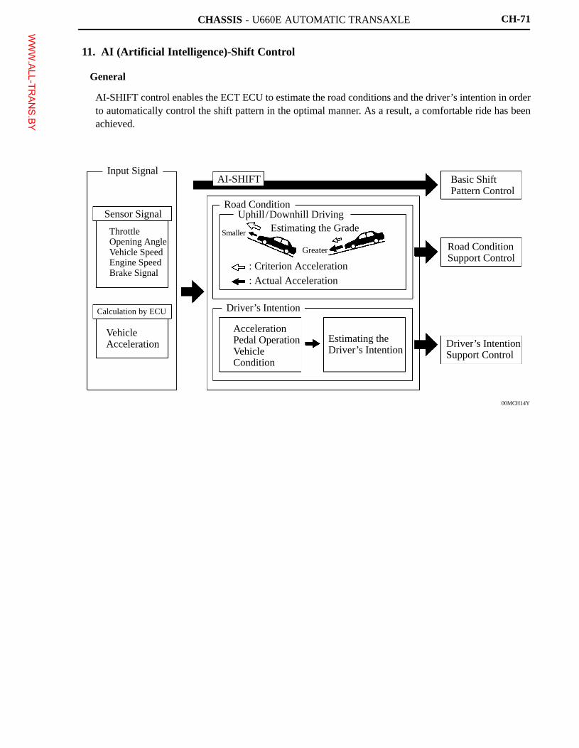
11. AI (Artificial Intelligence)-Shift Control
General
AI-SHIFT control enables the ECT ECU to estimate the road conditions and the driver’s intention in orderto automatically control the shift pattern in the optimal manner. As a result, a comfortable ride has beenachieved.
WWW.ALL-TR
ANS.BY

CHASSIS - U660E AUTOMATIC TRANSAXLE
040SC13C
6th
6th
4th 5th
4th 3rd
3rd 5th 4th5th
(Brake Operating)
4th 3rd 4th
6th
5th 6th
without Control
with Control
CH-72
Road Condition Support Control
Under road condition support control, ECT ECU determines the throttle valve opening angle and the vehiclespeed whether the vehicle is being driven uphill or downhill.To achieve the optimal drive force while driving uphill, this control prevents the transaxle from up shiftingto the 5th or 6th gear. To achieve the optimal engine brake effect while driving downhill, this controlautomatically downshifts the transaxle to the 5th or 4th or 3rd gear.
Driver’s Intention Support Control
Estimates the driver’s intention based on the accelerator operation and vehicle condition to switch to a shiftpattern that is well-suited to each driver, without the need to operate the shift pattern select switch used inthe conventional models.
WWW.ALL-TR
ANS.BY
CHASSIS - U660E AUTOMATIC TRANSAXLE
01YCH35Y
CAN(CAN No.1 Bus)
Combination Meter
Shift Range Indicator Light
S Mode Indicator Light
Buzzer
ECM
IgnitionAdvanceSignal
LocalCAN
ECT ECU
Engine
Solenoid ValveControl Signal
A/T
Shift-up Signal
Shift-down Signal
S Mode Position Signal
TransmissionControl Switch
CH-73
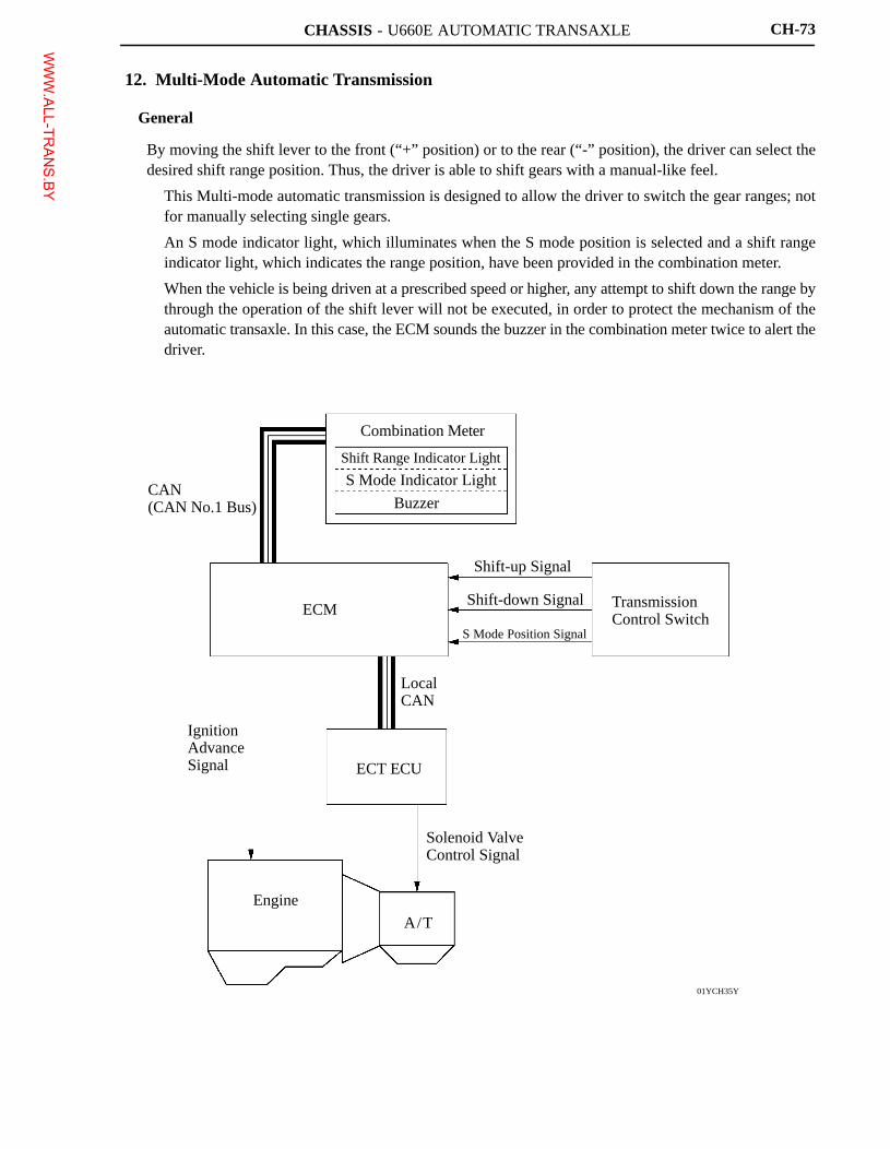
12. Multi-Mode Automatic Transmission
General
By moving the shift lever to the front (“+” position) or to the rear (“-” position), the driver can select thedesired shift range position. Thus, the driver is able to shift gears with a manual-like feel.
� This Multi-mode automatic transmission is designed to allow the driver to switch the gear ranges; notfor manually selecting single gears.
� An S mode indicator light, which illuminates when the S mode position is selected and a shift rangeindicator light, which indicates the range position, have been provided in the combination meter.
� When the vehicle is being driven at a prescribed speed or higher, any attempt to shift down the range bythrough the operation of the shift lever will not be executed, in order to protect the mechanism of theautomatic transaxle. In this case, the ECM sounds the buzzer in the combination meter twice to alert thedriver.
WWW.ALL-TR
ANS.BY
CHASSIS - U660E AUTOMATIC TRANSAXLE
030SC29C
Transition of ShiftRange Positions S Mode
Position
Shift Pattern
: Default Shift Range
CH-74
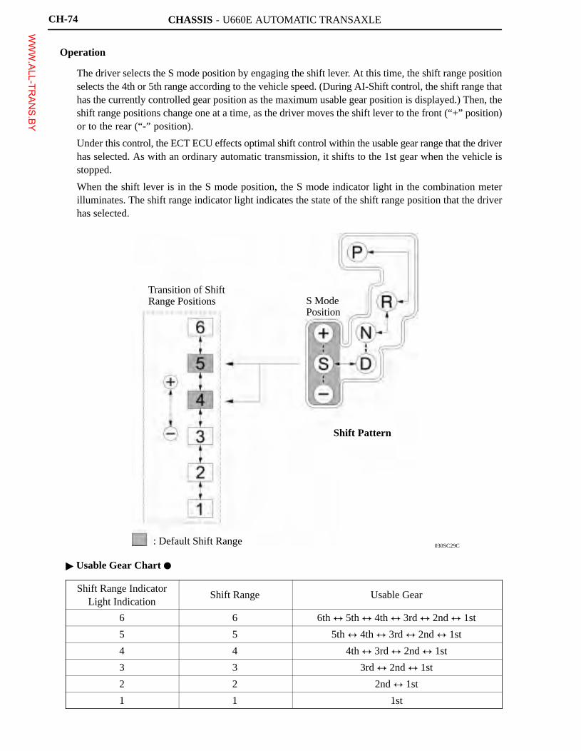
Operation
� The driver selects the S mode position by engaging the shift lever. At this time, the shift range positionselects the 4th or 5th range according to the vehicle speed. (During AI-Shift control, the shift range thathas the currently controlled gear position as the maximum usable gear position is displayed.) Then, theshift range positions change one at a time, as the driver moves the shift lever to the front (“+” position)or to the rear (“-” position).
� Under this control, the ECT ECU effects optimal shift control within the usable gear range that the driverhas selected. As with an ordinary automatic transmission, it shifts to the 1st gear when the vehicle isstopped.
� When the shift lever is in the S mode position, the S mode indicator light in the combination meterilluminates. The shift range indicator light indicates the state of the shift range position that the driverhas selected.
� Usable Gear Chart �
Shift Range IndicatorLight Indication
Shift Range Usable Gear
6 6 6th � 5th � 4th � 3rd � 2nd � 1st
5 5 5th � 4th � 3rd � 2nd � 1st
4 4 4th � 3rd � 2nd � 1st
3 3 3rd � 2nd � 1st
2 2 2nd � 1st
1 1 1st
WWW.ALL-TR
ANS.BY
CHASSIS - U660E AUTOMATIC TRANSAXLE
Service Tip
The ECM uses the CAN protocol for diagnostic communication. Therefore, a hand-held tester anda dedicated adapter [CAN VIM (Vehicle Interface Module)] are required for accessing diagnosticdata. For details, see the 2007 Camry Repair Manual (Pub. No. RM0250U).
CH-75
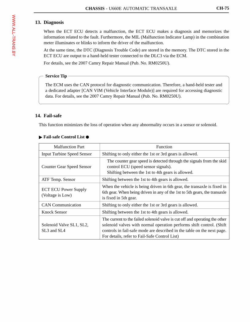
13. Diagnosis
� When the ECT ECU detects a malfunction, the ECT ECU makes a diagnosis and memorizes theinformation related to the fault. Furthermore, the MIL (Malfunction Indicator Lamp) in the combinationmeter illuminates or blinks to inform the driver of the malfunction.
� At the same time, the DTC (Diagnosis Trouble Code) are stored in the memory. The DTC stored in theECT ECU are output to a hand-held tester connected to the DLC3 via the ECM.
� For details, see the 2007 Camry Repair Manual (Pub. No. RM0250U).
14. Fail-safe
This function minimizes the loss of operation when any abnormality occurs in a sensor or solenoid.
� Fail-safe Control List �
Malfunction Part Function
Input Turbine Speed Sensor Shifting to only either the 1st or 3rd gears is allowed.
Counter Gear Speed Sensor� The counter gear speed is detected through the signals from the skid
control ECU (speed sensor signals).� Shifting between the 1st to 4th gears is allowed.
ATF Temp. Sensor Shifting between the 1st to 4th gears is allowed.
ECT ECU Power Supply (Voltage is Low)
When the vehicle is being driven in 6th gear, the transaxle is fixed in6th gear. When being driven in any of the 1st to 5th gears, the transaxleis fixed in 5th gear.
CAN Communication Shifting to only either the 1st or 3rd gears is allowed.
Knock Sensor Shifting between the 1st to 4th gears is allowed.
Solenoid Valve SL1, SL2, SL3 and SL4
The current to the failed solenoid valve is cut off and operating the othersolenoid valves with normal operation performs shift control. (Shiftcontrols in fail-safe mode are described in the table on the next page.For details, refer to Fail-Safe Control List)
WWW.ALL-TR
ANS.BY
CHASSIS - U660E AUTOMATIC TRANSAXLECH-76
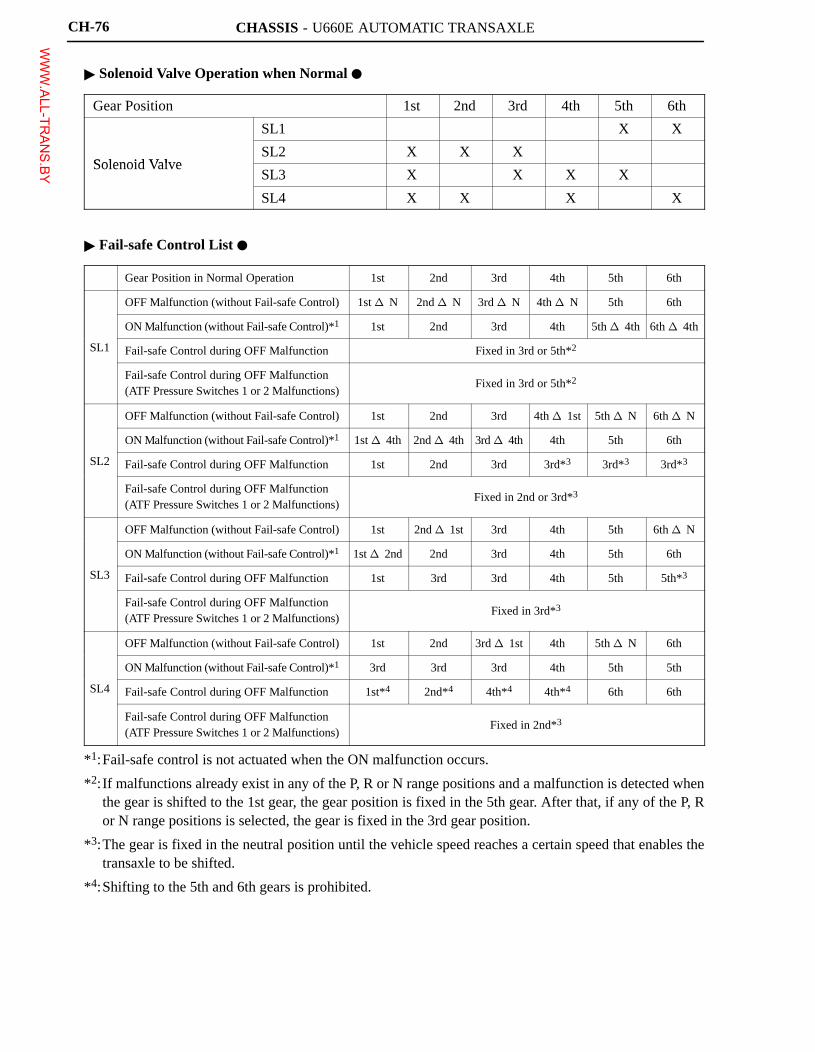
� Solenoid Valve Operation when Normal �
Gear Position 1st 2nd 3rd 4th 5th 6th
SL1 � � � � X X
Solenoid ValveSL2 X X X � � �
Solenoid ValveSL3 X � X X X �
SL4 X X � X � X
� Fail-safe Control List �
Gear Position in Normal Operation 1st 2nd 3rd 4th 5th 6th
OFF Malfunction (without Fail-safe Control) 1st � N 2nd � N 3rd � N 4th � N 5th 6th
ON Malfunction (without Fail-safe Control)*1 1st 2nd 3rd 4th 5th � 4th 6th � 4th
SL1 Fail-safe Control during OFF Malfunction Fixed in 3rd or 5th*2
Fail-safe Control during OFF Malfunction(ATF Pressure Switches 1 or 2 Malfunctions)
Fixed in 3rd or 5th*2
OFF Malfunction (without Fail-safe Control) 1st 2nd 3rd 4th � 1st 5th � N 6th � N
ON Malfunction (without Fail-safe Control)*1 1st � 4th 2nd � 4th 3rd � 4th 4th 5th 6th
SL2 Fail-safe Control during OFF Malfunction 1st 2nd 3rd 3rd*3 3rd*3 3rd*3
Fail-safe Control during OFF Malfunction(ATF Pressure Switches 1 or 2 Malfunctions)
Fixed in 2nd or 3rd*3
OFF Malfunction (without Fail-safe Control) 1st 2nd � 1st 3rd 4th 5th 6th � N
ON Malfunction (without Fail-safe Control)*1 1st � 2nd 2nd 3rd 4th 5th 6th
SL3 Fail-safe Control during OFF Malfunction 1st 3rd 3rd 4th 5th 5th*3
Fail-safe Control during OFF Malfunction(ATF Pressure Switches 1 or 2 Malfunctions)
Fixed in 3rd*3
OFF Malfunction (without Fail-safe Control) 1st 2nd 3rd � 1st 4th 5th � N 6th
ON Malfunction (without Fail-safe Control)*1 3rd 3rd 3rd 4th 5th 5th
SL4 Fail-safe Control during OFF Malfunction 1st*4 2nd*4 4th*4 4th*4 6th 6th
Fail-safe Control during OFF Malfunction(ATF Pressure Switches 1 or 2 Malfunctions)
Fixed in 2nd*3
*1:Fail-safe control is not actuated when the ON malfunction occurs.
*2:If malfunctions already exist in any of the P, R or N range positions and a malfunction is detected whenthe gear is shifted to the 1st gear, the gear position is fixed in the 5th gear. After that, if any of the P, Ror N range positions is selected, the gear is fixed in the 3rd gear position.
*3:The gear is fixed in the neutral position until the vehicle speed reaches a certain speed that enables thetransaxle to be shifted.
*4:Shifting to the 5th and 6th gears is prohibited.
WWW.ALL-TR
ANS.BY
CHASSIS - U660E AUTOMATIC TRANSAXLE
01YCH06Y
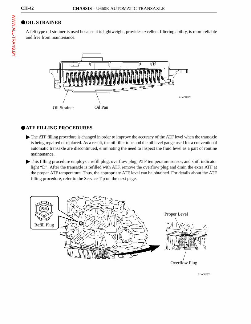
Oil Strainer Oil Pan
01YCH07Y
Refill Plug
Proper Level
Overflow Plug
CH-42
�OIL STRAINER
A felt type oil strainer is used because it is lightweight, provides excellent filtering ability, is more reliableand free from maintenance.
�ATF FILLING PROCEDURES
� The ATF filling procedure is changed in order to improve the accuracy of the ATF level when the transaxleis being repaired or replaced. As a result, the oil filler tube and the oil level gauge used for a conventionalautomatic transaxle are discontinued, eliminating the need to inspect the fluid level as a part of routinemaintenance.
� This filling procedure employs a refill plug, overflow plug, ATF temperature sensor, and shift indicatorlight “D”. After the transaxle is refilled with ATF, remove the overflow plug and drain the extra ATF atthe proper ATF temperature. Thus, the appropriate ATF level can be obtained. For details about the ATFfilling procedure, refer to the Service Tip on the next page.
WWW.ALL-TR
ANS.BY
CHASSIS - U660E AUTOMATIC TRANSAXLE
Service Tip
ATF Filling procedure using SST (09843-18040)
When a large amount of ATF needs to be filled (i.e. after removal and installation of oil pan or torqueconverter), perform the procedure from step 1.When a small amount of ATF is required (i.e. removal and installation of oil cooler tube, repair ofa minor oil leak), perform the procedure from step 7.
1) Raise the vehicle while keeping it level.2) Remove the refill plug and overflow plug.3) Fill the transaxle with WS type ATF through the refill plug hole until it overflows from the
overflow plug hole.� ATF WS must be used to fill the transaxle.
4) Reinstall the overflow plug.5) Add the specified amount of ATF (specified amount is determined by the procedure that was
performed) and reinstall the refill plug.
Example:
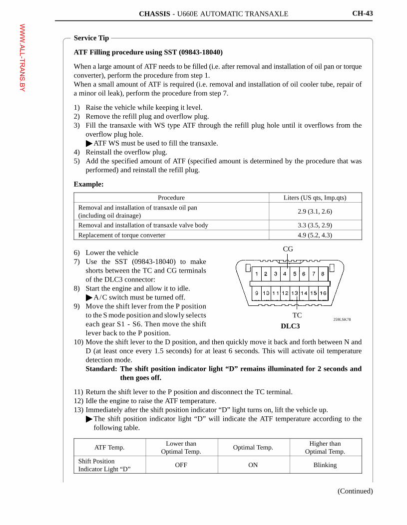
6) Lower the vehicle7) Use the SST (09843-18040) to make
shorts between the TC and CG terminalsof the DLC3 connector:
8) Start the engine and allow it to idle.� A/C switch must be turned off.
9) Move the shift lever from the P positionto the S mode position and slowly selectseach gear S1 - S6. Then move the shiftlever back to the P position.
10) Move the shift lever to the D position, and then quickly move it back and forth between N andD (at least once every 1.5 seconds) for at least 6 seconds. This will activate oil temperaturedetection mode.Standard: The shift position indicator light “D” remains illuminated for 2 seconds and
then goes off.
11) Return the shift lever to the P position and disconnect the TC terminal.12) Idle the engine to raise the ATF temperature.13) Immediately after the shift position indicator “D” light turns on, lift the vehicle up.
� The shift position indicator light “D” will indicate the ATF temperature according to thefollowing table.
259LSK78
CG
TC
DLC3
CH-43
Procedure Liters (US qts, Imp.qts)
Removal and installation of transaxle oil pan(including oil drainage)
2.9 (3.1, 2.6)
Removal and installation of transaxle valve body 3.3 (3.5, 2.9)
Replacement of torque converter 4.9 (5.2, 4.3)
ATF Temp.Lower than
Optimal Temp.Optimal Temp.
Higher thanOptimal Temp.
Shift PositionIndicator Light “D”
OFF ON Blinking
(Continued)
WWW.ALL-TR
ANS.BY
CHASSIS - U660E AUTOMATIC TRANSAXLE
14) Remove the overflow plug and adjust the oil quantity.� If the ATF overflows, go to step 17, and if the ATF does not overflow, go to step 15.
15) Remove the refill plug.16) Add ATF through the refill plug hole until it flows out from the overflow plug hole.17) When the ATF flow slows to a trickle, install the overflow plug and a new gasket.18) Reinstall the refill plug (if the refill plug was removed).19) Lower the vehicle.20) Turn the ignition switch (engine switch) OFF to stop the engine.
For details about the ATF Filling procedures, see the 2007 Camry Repair Manual (Pub. No.RM0250U).
CH-44
WWW.ALL-TR
ANS.BY
CHASSIS - U660E AUTOMATIC TRANSAXLE
01YCH03Y
Intermediate Shaft
Ravigneaux Planetary Gear Unit
Rear Sun Gear
Ring Gear
Front Sun Gear
Counter Driven Gear
Ring Gear
Differential Drive Pinion
Counter Drive Gear
Ring Gear
Sun Gear
Input Shaft
Pinion Gear
U/D Planetary Gear Unit
Short Pinion GearC2
C1
F1 B2 B3 B1
Long Pinion Gear
CH-45
�PLANETARY GEAR UNIT
1. Construction
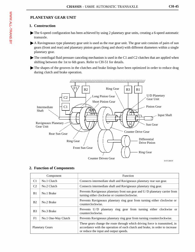
� The 6-speed configuration has been achieved by using 2 planetary gear units, creating a 6-speed automatictransaxle.
� A Ravingneaux type planetary gear unit is used as the rear gear unit. The gear unit consists of pairs of sungears (front and rear) and planetary pinion gears (long and short) with different diameters within a singleplanetary gear.
� The centrifugal fluid pressure canceling mechanism is used in the C1 and C2 clutches that are applied whenshifting between the 1st to 6th gears. Refer to CH-51 for details.
� The shapes of the grooves in the clutches and brake linings have been optimized in order to reduce dragduring clutch and brake operation.
2. Function of Components
Component Function
C1 No.1 Clutch Connects intermediate shaft and Ravigneaux planetary rear sun gear.
C2 No.2 Clutch Connects intermediate shaft and Ravigneaux planetary ring gear.
B1 No.1 BrakePrevents Ravigneaux planetary front sun gear and U/D planetary carrier fromturning either clockwise or counterclockwise.
B2 No.2 BrakePrevents Ravigneaux planetary ring gear from turning either clockwise orcounterclockwise.
B3 No.3 BrakePrevents U/D planetary ring gear from turning either clockwise orcounterclockwise.
F1 No.1 One-Way Clutch Prevents Ravigneaux planetary ring gear from turning counterclockwise.
Planetary GearsThese gears change the route through which driving force is transmitted, inaccordance with the operation of each clutch and brake, in order to increaseor reduce the input and output speeds.
WWW.ALL-TR
ANS.BY
CHASSIS - U660E AUTOMATIC TRANSAXLECH-46
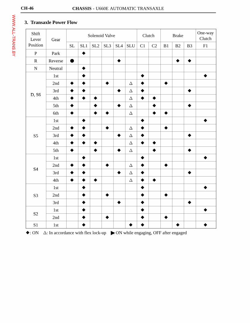
3. Transaxle Power Flow
ShiftLever Gear
Solenoid Valve Clutch BrakeOne-wayClutchLever
PositionGear
SL SL1 SL2 SL3 SL4 SLU C1 C2 B1 B2 B3 F1
P Park �
R Reverse � � � �
N Neutral �
1st � � �
2nd � � � � � �
D S63rd � � � � � �
D, S64th � � � � � �
5th � � � � � �
6th � � � � � �
1st � � �
2nd � � � � � �
S5 3rd � � � � � �
4th � � � � � �
5th � � � � � �
1st � � �
S42nd � � � � � �
S43rd � � � � � �
4th � � � � � �
1st � � �
S3 2nd � � � �
3rd � � � �
S21st � � �
S22nd � � � �
S1 1st � � � � �
�: ON �: In accordance with flex lock-up�: ON while engaging, OFF after engagedWWW.ALL-TR
ANS.BY
CHASSIS - U660E AUTOMATIC TRANSAXLE
01YCH08Y
C2
C1
F1 B2 B3 B1
Input
01YCH09Y
C2
F1
C1
B2 B3 B1
Input
CH-47
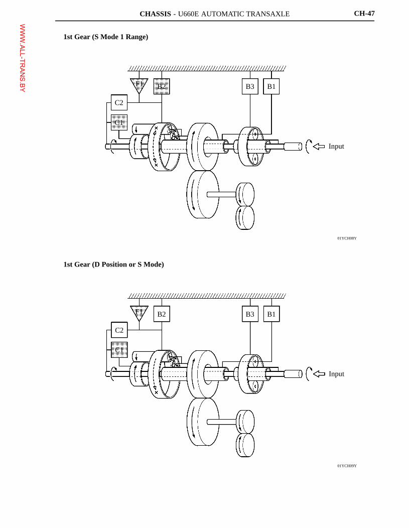
1st Gear (S Mode 1 Range)
1st Gear (D Position or S Mode)
WWW.ALL-TR
ANS.BY
CHASSIS - U660E AUTOMATIC TRANSAXLE
01YCH10Y
C2
C1
F1 B2 B3 B1
Input
01YCH11Y
C2
C1
F1 B2 B3 B1
Input
CH-48
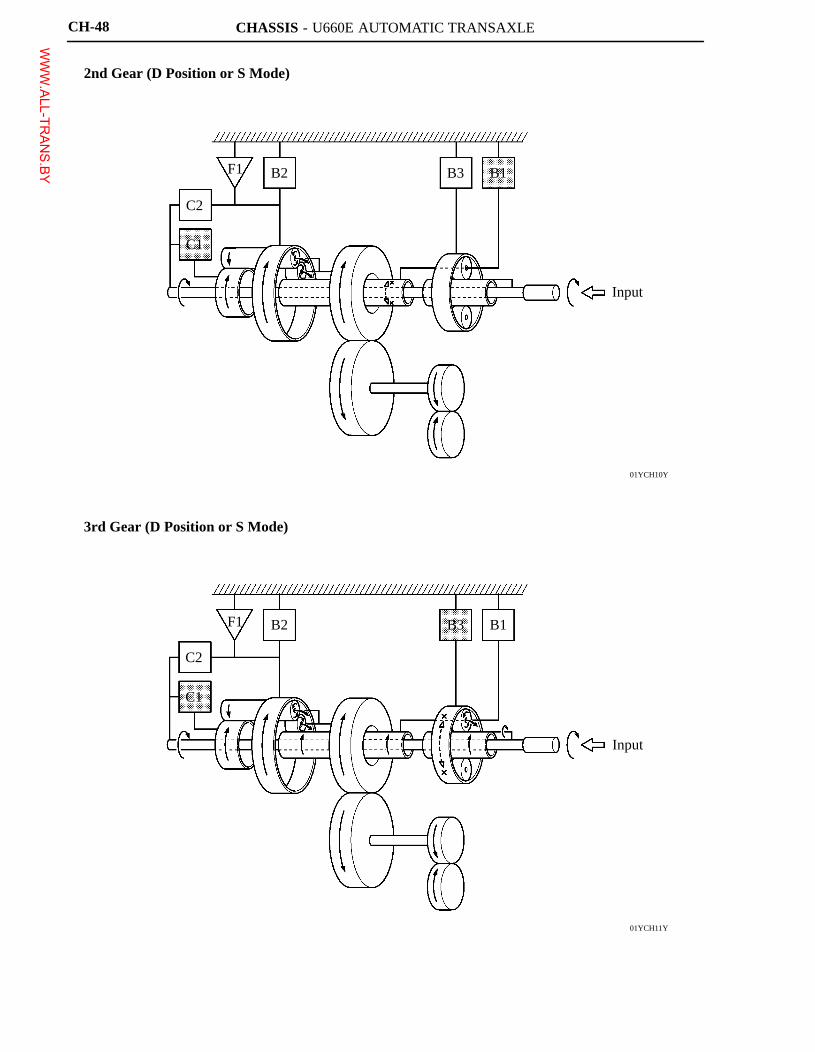
2nd Gear (D Position or S Mode)
3rd Gear (D Position or S Mode)
WWW.ALL-TR
ANS.BY
CHASSIS - U660E AUTOMATIC TRANSAXLE
01YCH12Y
C2
C1
F1 B2 B3 B1
Input
01YCH13Y
C1
C2
F1 B2 B3 B1
Input
CH-49
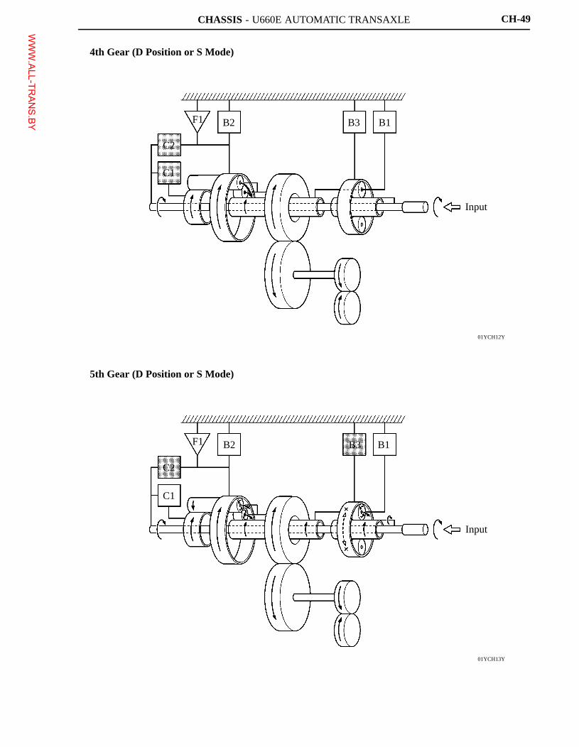
4th Gear (D Position or S Mode)
5th Gear (D Position or S Mode)
WWW.ALL-TR
ANS.BY
CHASSIS - U660E AUTOMATIC TRANSAXLE
01YCH14Y
C2
C1
F1 B2 B3 B1
Input
01YCH15Y
C2
C1
F1 B2 B3 B1
Input
CH-50
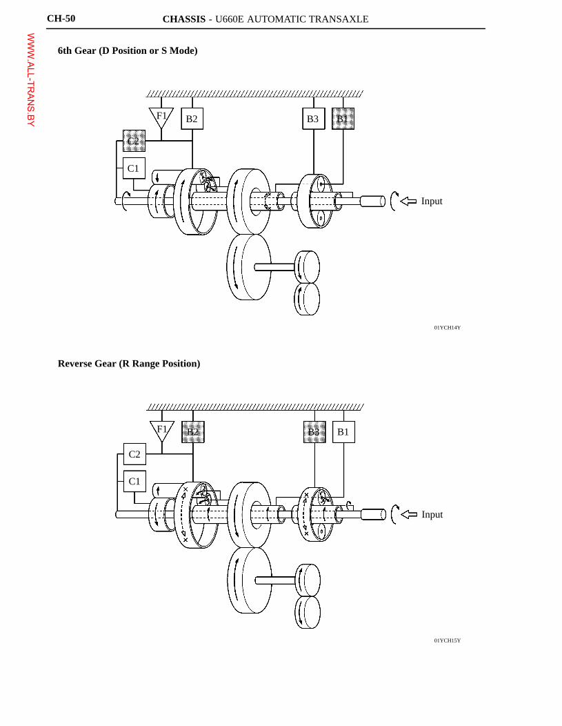
6th Gear (D Position or S Mode)
Reverse Gear (R Range Position)
WWW.ALL-TR
ANS.BY
CHASSIS - U660E AUTOMATIC TRANSAXLE
025CH27Y
Chamber B
Chamber AC1 C2
Piston Chamber B
157CH17
Shaft Side
Fluid pressure applied to piston
- Centrifugal fluid pressure applied to chamber B
Target fluid pressure (original clutch pressure)
=
Target Fluid Pressure
Piston Fluid Pressure Chamber
Fluid Pressure Applied to Piston
Chamber B (Lubrication Fluid)
Centrifugal Fluid Pressure Applied to Chamber B
ClutchCentrifugal Fluid Pressure Applied to Chamber A
CH-51
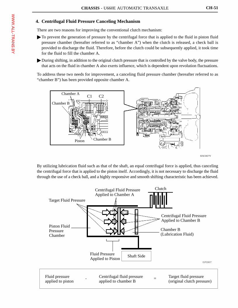
4. Centrifugal Fluid Pressure Canceling Mechanism
There are two reasons for improving the conventional clutch mechanism:
� To prevent the generation of pressure by the centrifugal force that is applied to the fluid in piston fluidpressure chamber (hereafter referred to as “chamber A”) when the clutch is released, a check ball isprovided to discharge the fluid. Therefore, before the clutch could be subsequently applied, it took timefor the fluid to fill the chamber A.
� During shifting, in addition to the original clutch pressure that is controlled by the valve body, the pressurethat acts on the fluid in chamber A also exerts influence, which is dependent upon revolution fluctuations.
To address these two needs for improvement, a canceling fluid pressure chamber (hereafter referred to as“chamber B”) has been provided opposite chamber A.
By utilizing lubrication fluid such as that of the shaft, an equal centrifugal force is applied, thus cancelingthe centrifugal force that is applied to the piston itself. Accordingly, it is not necessary to discharge the fluidthrough the use of a check ball, and a highly responsive and smooth shifting characteristic has been achieved.
WWW.ALL-TR
ANS.BY
CHASSIS - U660E AUTOMATIC TRANSAXLE
01YCH17Y
Angular Ball Bearing
Counter Drive Gear Elongated Opening
Counter Drive Gear
01YCH18Y
Spring
Piston (Split type)
Piston (Non-split Type)
Divided Portion
C1 C2
Piston (Split type)
Counter Drive Gear
Piston B3
CH-52
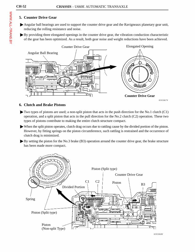
5. Counter Drive Gear
� Angular ball bearings are used to support the counter drive gear and the Ravigneaux planetary gear unit,reducing the rolling resistance and noise.
� By providing three elongated openings in the counter drive gear, the vibration conduction characteristicof the gear has been optimized. As a result, both gear noise and weight reductions have been achieved.
6. Clutch and Brake Pistons
� Two types of pistons are used; a non-split piston that acts in the push direction for the No.1 clutch (C1)operation, and a split piston that acts in the pull direction for the No.2 clutch (C2) operation. These twotypes of pistons contribute to making the entire clutch structure compact.
� When the split piston operates, clutch drag occurs due to rattling cause by the divided portion of the piston.However, by fitting springs on the piston circumference, such rattling is restrained and the occurrence ofclutch drag is minimized.
� By setting the piston for the No.3 brake (B3) operation around the counter drive gear, the brake structurehas been made more compact.
WWW.ALL-TR
ANS.BY
CHASSIS - U660E AUTOMATIC TRANSAXLE
025CH18TE
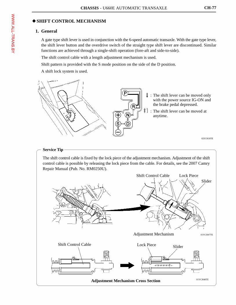
: The shift lever can be moved onlywith the power source IG-ON andthe brake pedal depressed.
: The shift lever can be moved atanytime.
Service Tip
The shift control cable is fixed by the lock piece of the adjustment mechanism. Adjustment of the shiftcontrol cable is possible by releasing the lock piece from the cable. For details, see the 2007 CamryRepair Manual (Pub. No. RM0250U).
01YCH47TE
01YCH48TE
Shift Control Cable Lock PieceSlider
Adjustment Mechanism
Shift Control Cable Lock Piece Slider
Adjustment Mechanism Cross Section
CH-77
�SHIFT CONTROL MECHANISM
1. General
� A gate type shift lever is used in conjunction with the 6-speed automatic transaxle. With the gate type lever,the shift lever button and the overdrive switch of the straight type shift lever are discontinued. Similarfunctions are achieved through a single-shift operation (fore-aft and side-to-side).
� The shift control cable with a length adjustment mechanism is used.
� Shift pattern is provided with the S mode position on the side of the D position.
� A shift lock system is used.
WWW.ALL-TR
ANS.BY
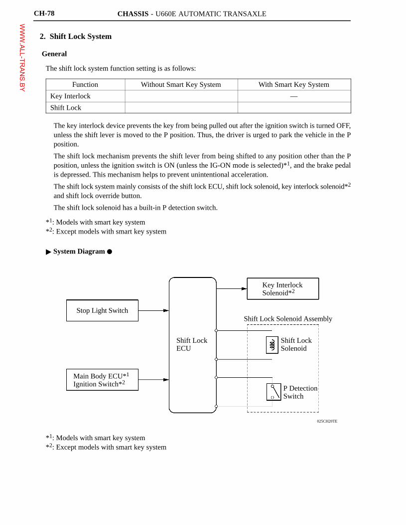
CHASSIS - U660E AUTOMATIC TRANSAXLE
025CH20TE
Stop Light Switch
Main Body ECU*1Ignition Switch*2
Shift LockECU
Key InterlockSolenoid*2
Shift Lock Solenoid Assembly
Shift LockSolenoid
P DetectionSwitch
CH-78
2. Shift Lock System
General
The shift lock system function setting is as follows:
Function Without Smart Key System With Smart Key System
Key Interlock � —
Shift Lock � �
� The key interlock device prevents the key from being pulled out after the ignition switch is turned OFF,unless the shift lever is moved to the P position. Thus, the driver is urged to park the vehicle in the Pposition.
� The shift lock mechanism prevents the shift lever from being shifted to any position other than the Pposition, unless the ignition switch is ON (unless the IG-ON mode is selected)*1, and the brake pedalis depressed. This mechanism helps to prevent unintentional acceleration.
� The shift lock system mainly consists of the shift lock ECU, shift lock solenoid, key interlock solenoid*2
and shift lock override button.
� The shift lock solenoid has a built-in P detection switch.
*1: Models with smart key system*2: Except models with smart key system
� System Diagram �
*1: Models with smart key system*2: Except models with smart key system
WWW.ALL-TR
ANS.BY
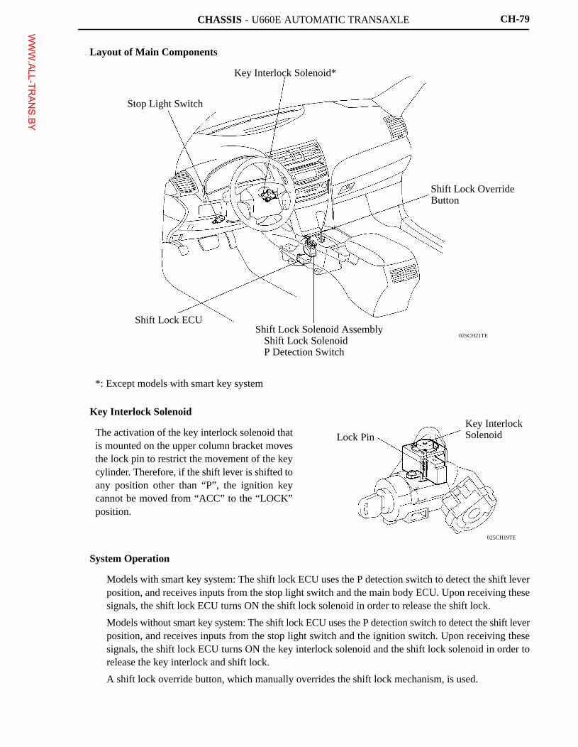
CHASSIS - U660E AUTOMATIC TRANSAXLE
025CH21TE
Stop Light Switch
Key Interlock Solenoid*
Shift Lock OverrideButton
Shift Lock Solenoid Assembly� Shift Lock Solenoid� P Detection Switch
Shift Lock ECU
025CH19TE
Lock PinKey InterlockSolenoid
CH-79
Layout of Main Components
*: Except models with smart key system
Key Interlock Solenoid
The activation of the key interlock solenoid thatis mounted on the upper column bracket movesthe lock pin to restrict the movement of the keycylinder. Therefore, if the shift lever is shifted toany position other than “P”, the ignition keycannot be moved from “ACC” to the “LOCK”position.
System Operation
� Models with smart key system: The shift lock ECU uses the P detection switch to detect the shift leverposition, and receives inputs from the stop light switch and the main body ECU. Upon receiving thesesignals, the shift lock ECU turns ON the shift lock solenoid in order to release the shift lock.
� Models without smart key system: The shift lock ECU uses the P detection switch to detect the shift leverposition, and receives inputs from the stop light switch and the ignition switch. Upon receiving thesesignals, the shift lock ECU turns ON the key interlock solenoid and the shift lock solenoid in order torelease the key interlock and shift lock.
� A shift lock override button, which manually overrides the shift lock mechanism, is used.
WWW.ALL-TR
ANS.BY
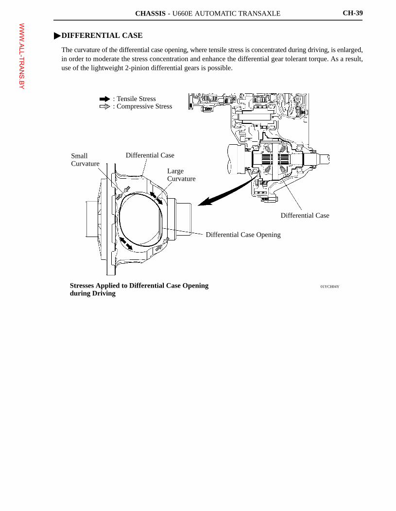
CHASSIS - U660E AUTOMATIC TRANSAXLE
01YCH04Y
: Tensile Stress: Compressive Stress
Differential Case
SmallCurvature
Differential Case
LargeCurvature
Differential Case Opening
Stresses Applied to Differential Case Openingduring Driving
CH-39
�DIFFERENTIAL CASE
The curvature of the differential case opening, where tensile stress is concentrated during driving, is enlarged,in order to moderate the stress concentration and enhance the differential gear tolerant torque. As a result,use of the lightweight 2-pinion differential gears is possible.
WWW.ALL-TR
ANS.BY
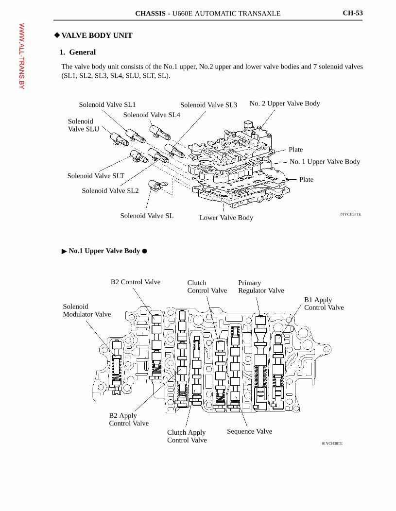
CHASSIS - U660E AUTOMATIC TRANSAXLE
01YCH37TE
Solenoid Valve SL1
Solenoid Valve SL4
Solenoid Valve SL3 No. 2 Upper Valve Body
Plate
No. 1 Upper Valve Body
Plate
Lower Valve BodySolenoid Valve SL
Solenoid Valve SL2
Solenoid Valve SLT
Solenoid Valve SLU
01YCH38TE
Solenoid Modulator Valve
B2 Control Valve Clutch Control Valve
Primary Regulator Valve
B1 Apply Control Valve
Sequence ValveClutch Apply Control Valve
B2 Apply Control Valve
CH-53
�VALVE BODY UNIT
1. General
The valve body unit consists of the No.1 upper, No.2 upper and lower valve bodies and 7 solenoid valves(SL1, SL2, SL3, SL4, SLU, SLT, SL).
� No.1 Upper Valve Body �
WWW.ALL-TR
ANS.BY
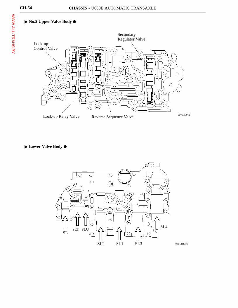
CHASSIS - U660E AUTOMATIC TRANSAXLE
01YCH39TE
Lock-up Control Valve
Secondary Regulator Valve
Reverse Sequence ValveLock-up Relay Valve
01YCH40TE
SLSLT SLU
SL2 SL1 SL3
SL4
CH-54
� No.2 Upper Valve Body �
� Lower Valve Body �
WWW.ALL-TR
ANS.BY
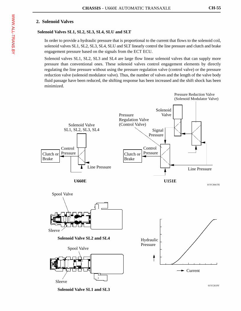
CHASSIS - U660E AUTOMATIC TRANSAXLE
01YCH41TE
01YCH19Y
Clutch orBrake
Control Pressure
Solenoid ValveSL1, SL2, SL3, SL4
Line Pressure
U660E
Pressure Regulation Valve (Control Valve)
Clutch orBrake
ControlPressure
SignalPressure
SolenoidValve
Pressure Reduction Valve (Solenoid Modulator Valve)
Line Pressure
U151E
Spool Valve
Sleeve
Solenoid Valve SL2 and SL4
Spool Valve
Sleeve
Solenoid Valve SL1 and SL3
Hydraulic Pressure
Current
CH-55
2. Solenoid Valves
Solenoid Valves SL1, SL2, SL3, SL4, SLU and SLT
� In order to provide a hydraulic pressure that is proportional to the current that flows to the solenoid coil,solenoid valves SL1, SL2, SL3, SL4, SLU and SLT linearly control the line pressure and clutch and brakeengagement pressure based on the signals from the ECT ECU.
� Solenoid valves SL1, SL2, SL3 and SL4 are large flow linear solenoid valves that can supply morepressure than conventional ones. These solenoid valves control engagement elements by directlyregulating the line pressure without using the pressure regulation valve (control valve) or the pressurereduction valve (solenoid modulator valve). Thus, the number of valves and the length of the valve bodyfluid passage have been reduced, the shifting response has been increased and the shift shock has beenminimized.
WWW.ALL-TR
ANS.BY
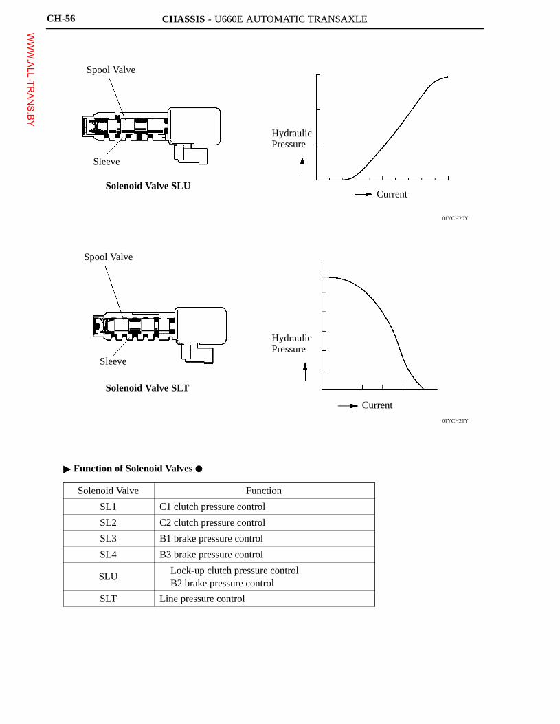
CHASSIS - U660E AUTOMATIC TRANSAXLE
01YCH20Y
01YCH21Y
Spool Valve
Sleeve
Solenoid Valve SLU
Hydraulic Pressure
Current
Spool Valve
Sleeve
Solenoid Valve SLT
Hydraulic Pressure
Current
CH-56
� Function of Solenoid Valves �
Solenoid Valve Function
SL1 C1 clutch pressure control
SL2 C2 clutch pressure control
SL3 B1 brake pressure control
SL4 B3 brake pressure control
SLU� Lock-up clutch pressure control� B2 brake pressure control
SLT Line pressure control
WWW.ALL-TR
ANS.BY
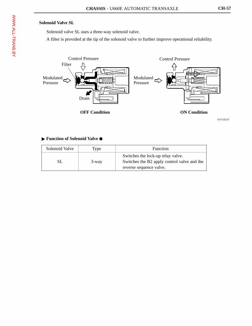
CHASSIS - U660E AUTOMATIC TRANSAXLE
01YCH22Y
Modulated Pressure
FilterControl Pressure
Drain
OFF Condition
Modulated Pressure
Control Pressure
ON Condition
CH-57
Solenoid Valve SL
� Solenoid valve SL uses a three-way solenoid valve.
� A filter is provided at the tip of the solenoid valve to further improve operational reliability.
� Function of Solenoid Valve �
Solenoid Valve Type Function
SL 3-way� Switches the lock-up relay valve.� Switches the B2 apply control valve and the
reverse sequence valve.
WWW.ALL-TR
ANS.BY