Embed Size (px)
Citation preview

Micro MotionTM
ATEX Installation Drawings and Instructions for LFT Transmitters
For ATEX-approved installations
Installation InstructionsP/N 20002600, Rev. AJanuary 2005

ATEX Installation Drawings and Instructions for LFT Transmitters
For ATEX-approved installations
For technical assistance, phone the support center nearest you:• In U.S.A., phone 1-800-522-MASS (1-800-522-6277)• In Canada and Latin America, phone (303) 527-5200• In Asia, phone (65) 6770-8155• In the U.K., phone 0800 - 966 180 (toll-free)• Outside the U.K., phone +31 (0) 318 495 670
©2005, Micro Motion, Inc. All rights reserved. Micro Motion is a registered trademark of Micro Motion, Inc. The Micro Motion and Emerson logos are trademarks of Emerson Electric Co. All other trademarks are property of their respective owners.


Contents
ATEX Installation Drawings and Instructions v
Model LFT TransmittersInstallation Instructions . . . . . . . . . . . . . . . . . . . . . . . . . . . . . . . . . . . . . 1
Installation Drawings . . . . . . . . . . . . . . . . . . . . . . . . . . . . . . . . . . . . . . . 6Model LFT field-mount mA/FO transmitter to LF sensor . . . . . . . . . . . . . . . . . . . . . . . . . . . . . 6
Model LFT field-mount fieldbus transmitter to LF sensor . . . . . . . . . . . . . . . . . . . . . . . . . . . . 7
Model LFT field-mount Profibus-PA transmitter to LF sensor. . . . . . . . . . . . . . . . . . . . . . . . . . 8
Model LFT field-mount config-I/O transmitter to LF sensor . . . . . . . . . . . . . . . . . . . . . . . . . . . 9

vi ATEX Installation Drawings and Instructions

1
Model LFT TransmittersATEX Installation Instructions and Drawings
• For installing a Model LFT transmitter with a 4-wire connection to an LF sensor
Subject: Equipment type Transmitter type LFT***L****
Manufactured and submitted for examination
Micro Motion, Inc.
Address Boulder, Co. 80301, USA
Standard basis EN 50021:1999 Non-sparking ´n´
EN 50281-1-1:1998 Dust ´D´
Code for type of protection EEx nC IIB +H2 T6
EEx nC IIC T6
EEx nC [L] IIB +H2 T6
EEx nC [L] IIC T6
ATEX Installation Instructions

Model LFT Transmitters
2 ATEX Installation Instructions
1) Subject and type
Transmitter type LFT***L****
Instead of the *** letters and numerals will be inserted which characterize the following modifications:
Marking without influence to the type of protection
L F T * * * L * * *
Letter for conduit connections
Numeral for outputs
1 = One mA, one frequency flow only fieldmount EEx n C
3 = One mA, one frequency multivariable field mount EEx n C
4 = Two mA, two frequency configurable field mount EEx n C
6 = Foundation fieldbus field mount EEx nC [L]7 = Profibus-PA field mount EEx nC [L]
*
Numeral for display
1 = Standard display; gas group IIB+H2 2 = Backlight display; gas group IIB+H2 3 = No display; gas group IIC4 = IIC display cover; gas group IIC5 = IIC display cover with backlight display;
gas group IIC
Approval
L = ATEX — Equipment Category 3 (Zone 2)
Model LFT Transmitters
ATEX Installation Instructions 3
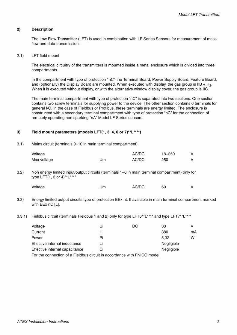
2) Description
The Low Flow Transmitter (LFT) is used in combination with LF Series Sensors for measurement of mass flow and data transmission.
2.1) LFT field mount
The electrical circuitry of the transmitters is mounted inside a metal enclosure which is divided into three compartments.
In the compartment with type of protection “nC” the Terminal Board, Power Supply Board, Feature Board, and (optionally) the Display Board are mounted. When executed with display, the gas group is IIB + H2. When it is executed without display, or with the alternative window display cover, the gas group is IIC.
The main terminal compartment with type of protection “nC” is separated into two sections. One section contains two screw terminals for supplying power to the device. The other section contains 6 terminals for general I/O. In the case of Fieldbus or Profibus, these terminals are energy limited. The enclosure is constructed with a secondary terminal compartment with type of protection “nC” for the connection of remotely operating non sparking “nA” Model LF Series sensors.
3) Field mount parameters (models LFT(1, 3, 4, 6 or 7)**L****)
3.1) Mains circuit (terminals 9–10 in main terminal compartment)
3.2) Non energy limited input/output circuits (terminals 1–6 in main terminal compartment) only for type LFT(1, 3 or 4)**L****
3.3) Energy limited output circuits type of protection EEx nL II available in main terminal compartment marked with EEx nC [L].
3.3.1) Fieldbus circuit (terminals Fieldbus 1 and 2) only for type LFT6**L**** and type LFT7**L****
Voltage AC/DC 18–250 V
Max voltage Um AC/DC 250 V
Voltage Um AC/DC 60 V
Voltage Ui DC 30 V
Current Ii 380 mA
Power Pi 5,32 W
Effective internal inductance Li Negligible
Effective internal capacitance Ci Negligible
For the connection of a Fieldbus circuit in accordance with FNICO model

Model LFT Transmitters
4 ATEX Installation Instructions
3.4) Power and signal circuits in secondary terminal compartment marked with "nC" for type LFT1**L**** or LFT3**L**** or LFT4**L**** or LFT6**L**** or LFT7**L**** (to remotely mounted LF sensor):
3.5) Ambient temperature range
4) Marking
After de-energizing, delay 5 minutes before opening (models LFT(1, 3, 4, 6 or 7)**L**** only).
5) Special conditions for safe use / Installation instructions
5.1) For the application of the transmitter in an ambient temperature of less than –20 °C suitable cable and cable entries or conduit entries for this condition shall be used (models LFT*(1, 2 or 3)*L**** only).
5.2) When cable entries are used they shall conform to clause 7.2.6 of EN 50021.
5.3) For type LFT(6 or 7)**L**** only, the cover of the terminal compartment containing terminals 1–6 may be removed for short periods when the apparatus is in service to permit checking or adjustment of energized energy limited circuits.
Voltage Uo DC 16,31 V
Current Io 0,396 A
Power Po 5,96 W
LFT(1, 3, 4, 6 or 7)(1, 2, or 3)*L**** Ta –40 °C up to +55 °C
LFT(1, 3, 4, 6 or 7)(4 or 5)*L**** Ta –20 °C up to +55 °C
LFT*(1, 2 or 3)*L**** –40 °C ≤ Ta ≤ +55 °C
LFT(1, 3, 4, 6 or 7)(4 or 5)*L**** –20 °C ≤ Ta ≤ +55 °C
- type - type of protection
LFT(1, 3, or 4)(1 or 2)*L**** II 3 G EEx nC IIB + H2 T6
II 3 D IP66/IP67 T65 °CKEMA 04 ATEX 1273 X
LFT(6 or 7)(1 or 2)*L**** II 3 G EEx nC [L] IIB + H2 T6
II 3 D IP66/IP67 T65 °CKEMA 04 ATEX 1273 X
LFT(1, 3, or 4)(3, 4 or 5)*L**** II 3 G EEx nC IIC T6
II 3 D IP66/IP67 T65 °CKEMA 04 ATEX 1273 X
LFT(6 or 7)(3, 4 or 5)*L**** II 3 G EEx nC [L] IIC T6
II 3 D IP66/IP67 T65 °CKEMA 04 ATEX 1273 X

Model LFT Transmitters
ATEX Installation Instructions 5
5.4) A degree of ingress protection of at least IP 54 according to EN 60529 will only be achieved when cable and conduit entries providing IP54 according to EN 60529 are used. For applications in explosive atmospheres caused by air/dust mixtures, a degree of ingress protection of at least IP66/IP67 according to EN 60529 will only be achieved when cable and conduit entries are used that provide a degree of ingress protection of at least IP66/IP67 according to EN 60529.
5.5) Replacement of fuses is not allowed.

6 ATEX Installation Drawings
Model LFT Transmitters
Model LFT field-mount mA/FO transmitter to LF sensor
Hazardous AreaNo Display
EEx nC IIC T6With Display
EEx nC IIB + H2 T6EEx nC IIC T6
Refer to transmitter tag for complete hazardous area classification.
Model LFT Field Mount Transmitter
Bro
wn–
Bla
ck–
Blu
e–W
hite
–
4-wire cable supplied with sensor (wire termination required)
Equipment ground
USP+
USP–
I/O1+
(mA
HA
RT
+)
I/O1–
(mA H
ART–)I/O2+(FO+)
I/O2–(FO–)
I/O3+(RS485+)
I/O3–
(RS485–)
VACVDC
Hazardous AreaEEx nA IIC
4-wire cable supplied with sensor (cable supplied with integral molded connector for sensor termination)Refer to sensor tag for complete
hazardous area classification.
Micro Motion mass flowmeter system connection
Electronics: LFT Field MountSensor: Model LF
EB-20002237 Rev. A
Models: LF2M, LF3M, LF4M
(For temporary diagnostic use only)
ATEX Installation Drawings 7
Model LFT Transmitters
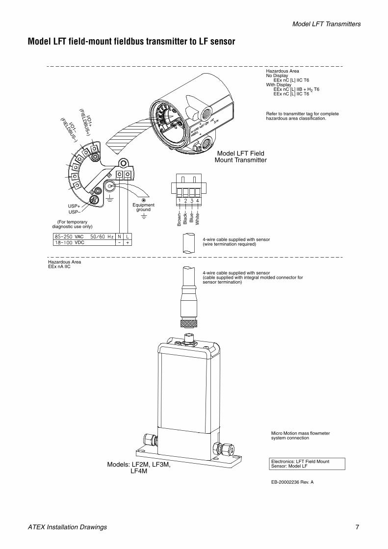
Model LFT field-mount fieldbus transmitter to LF sensor
Hazardous AreaNo Display
EEx nC [L] IIC T6With Display
EEx nC [L] IIB + H2 T6EEx nC [L] IIC T6
Refer to transmitter tag for complete hazardous area classification.
Model LFT Field Mount Transmitter
Bro
wn–
Bla
ck–
Blu
e–W
hite
–
4-wire cable supplied with sensor (wire termination required)
Equipment ground
USP+USP–
I/O1+
(FIE
LDB
US
+)
I/O1–
(FIELDBU
S–)
VACVDC
Hazardous AreaEEx nA IIC
4-wire cable supplied with sensor (cable supplied with integral molded connector for sensor termination)
Micro Motion mass flowmeter system connection
Electronics: LFT Field MountSensor: Model LF
EB-20002236 Rev. A
Models: LF2M, LF3M, LF4M
(For temporary diagnostic use only)
8 ATEX Installation Drawings
Model LFT Transmitters
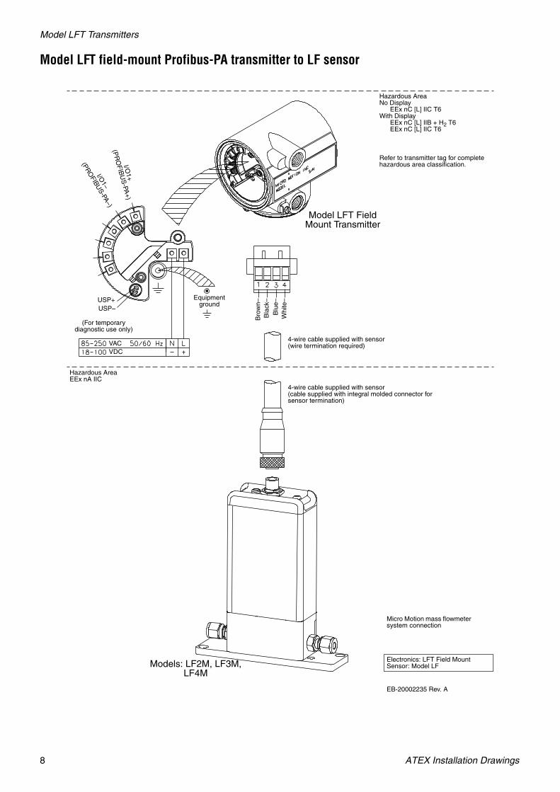
Model LFT field-mount Profibus-PA transmitter to LF sensor
Hazardous AreaNo Display
EEx nC [L] IIC T6With Display
EEx nC [L] IIB + H2 T6EEx nC [L] IIC T6
Refer to transmitter tag for complete hazardous area classification.
Model LFT Field Mount Transmitter
Bro
wn–
Bla
ck–
Blu
e–W
hite
–
4-wire cable supplied with sensor (wire termination required)
Equipment ground
USP+USP–
I/O1+
(PR
OF
IBU
S-PA
+)
I/O1–
(PRO
FIBUS-PA–)
VACVDC
Hazardous AreaEEx nA IIC
4-wire cable supplied with sensor (cable supplied with integral molded connector for sensor termination)
Micro Motion mass flowmeter system connection
Electronics: LFT Field MountSensor: Model LF
EB-20002235 Rev. A
Models: LF2M, LF3M, LF4M
(For temporary diagnostic use only)

ATEX Installation Drawings 9
Model LFT Transmitters
Model LFT field-mount config-I/O transmitter to LF sensor
Hazardous AreaNo Display
EEx nC IIC T6With Display
EEx nC IIB + H2 T6EEx nC IIC T6
Refer to transmitter tag for complete hazardous area classification.
Model LFT Field Mount Transmitter
Bro
wn–
Bla
ck–
Blu
e–W
hite
–
4-wire cable supplied with sensor (wire termination required)
Equipment ground
USP+USP–
mA
1 HA
RT
+
(CH
AN
NE
L A)
mA1 H
ART–
(CH
ANN
EL A)
mA2/D01/FO+
(CHANNEL B)mA2/D01/FO–(CHANNEL B)
FO/DO2/DI+
(CHANNEL C)
FO/DO2/DI–
(CHANNEL C)
VACVDC
Hazardous AreaEEx nA IIC
4-wire cable supplied with sensor (cable supplied with integral molded connector for sensor termination)Refer to sensor tag for complete
hazardous area classification.
Micro Motion mass flowmeter system connection
Electronics: LFT Field MountSensor: Model LF
EB-20002239 Rev. A
Models: LF2M, LF3M, LF4M
(For temporary diagnostic use only)

10 ATEX Installation Drawings


Micro MotionTM
©2004, Micro Motion, Inc. All rights reserved. P/N 20002600, Rev. A
*20002600*
Micro Motion Inc. USAWorldwide Headquarters7070 Winchester CircleBoulder, Colorado 80301T (303) 527-5200
(800) 522-6277F (303) 530-8459
Micro Motion EuropeEmerson Process ManagementWiltonstraat 303905 KW VeenendaalThe NetherlandsT +31 (0) 318 495 670F +31 (0) 318 495 689
Micro Motion United KingdomEmerson Process Management LimitedHorsfield WayBredbury Industrial EstateStockport SK6 2SU U.K.T 0800 966 180F 0800 966 181
Micro Motion JapanEmerson Process ManagementShinagawa NF Bldg. 5F1-2-5, Higashi ShinagawaShinagawa-kuTokyo 140-0002 JapanT (81) 3 5769-6803F (81) 3 5769-6843
Micro Motion AsiaEmerson Process Management1 Pandan CrescentSingapore 128461Republic of SingaporeT (65) 6777-8211F (65) 6770-8003
For the latest Micro Motion product specifications, view the PRODUCTS section of our Web site at www.micromotion.com