Embed Size (px)
Citation preview
ABB industrial drives
Application guideATEX-certified Safe disconnection functionfor ACS850 drives (+Q971)

List of related manuals
All manuals are available in PDF format on the Internet. See section Further information on the inside of the back cover.
Hardware and firmware manuals Code (English)ACS850-04 (1.1 to 45 kW) hardware manual 3AUA0000045496ACS850-04 (55 to 160 kW) hardware manual 3AUA0000045487ACS850-04 (200 to 500 kW) hardware manual 3AUA0000026234ACS850 Standard Control Program firmware manual 3AUA0000045497
Other Code (English)Application guide - Safe torque off function for ACSM1, ACS850 and ACQ810 drives
3AFE68929814
Technical catalogue - Electronic products and relays 2CDC110004C0206
Application guide
ATEX-certified Safe disconnection function for ACS850 drives (+Q971)
3AUA0000074343 Rev BEN
EFFECTIVE: 2011-04-05
© 2011 ABB Oy. All Rights Reserved.

5
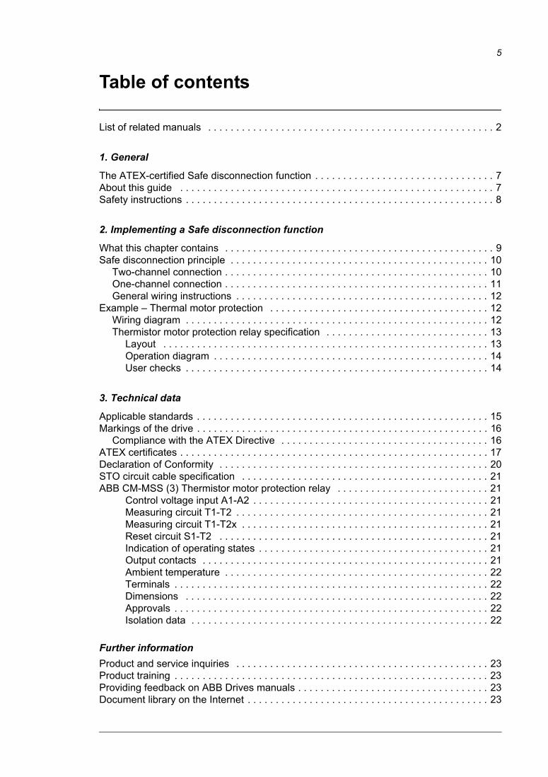
Table of contents
List of related manuals . . . . . . . . . . . . . . . . . . . . . . . . . . . . . . . . . . . . . . . . . . . . . . . . . . . 2
1. General
The ATEX-certified Safe disconnection function . . . . . . . . . . . . . . . . . . . . . . . . . . . . . . . . 7About this guide . . . . . . . . . . . . . . . . . . . . . . . . . . . . . . . . . . . . . . . . . . . . . . . . . . . . . . . . 7Safety instructions . . . . . . . . . . . . . . . . . . . . . . . . . . . . . . . . . . . . . . . . . . . . . . . . . . . . . . . 8
2. Implementing a Safe disconnection function
What this chapter contains . . . . . . . . . . . . . . . . . . . . . . . . . . . . . . . . . . . . . . . . . . . . . . . . 9Safe disconnection principle . . . . . . . . . . . . . . . . . . . . . . . . . . . . . . . . . . . . . . . . . . . . . . 10
Two-channel connection . . . . . . . . . . . . . . . . . . . . . . . . . . . . . . . . . . . . . . . . . . . . . . . 10One-channel connection . . . . . . . . . . . . . . . . . . . . . . . . . . . . . . . . . . . . . . . . . . . . . . . 11General wiring instructions . . . . . . . . . . . . . . . . . . . . . . . . . . . . . . . . . . . . . . . . . . . . . 12
Example – Thermal motor protection . . . . . . . . . . . . . . . . . . . . . . . . . . . . . . . . . . . . . . . 12Wiring diagram . . . . . . . . . . . . . . . . . . . . . . . . . . . . . . . . . . . . . . . . . . . . . . . . . . . . . . 12Thermistor motor protection relay specification . . . . . . . . . . . . . . . . . . . . . . . . . . . . . 13
Layout . . . . . . . . . . . . . . . . . . . . . . . . . . . . . . . . . . . . . . . . . . . . . . . . . . . . . . . . . . 13Operation diagram . . . . . . . . . . . . . . . . . . . . . . . . . . . . . . . . . . . . . . . . . . . . . . . . . 14User checks . . . . . . . . . . . . . . . . . . . . . . . . . . . . . . . . . . . . . . . . . . . . . . . . . . . . . . 14
3. Technical data
Applicable standards . . . . . . . . . . . . . . . . . . . . . . . . . . . . . . . . . . . . . . . . . . . . . . . . . . . . 15Markings of the drive . . . . . . . . . . . . . . . . . . . . . . . . . . . . . . . . . . . . . . . . . . . . . . . . . . . . 16
Compliance with the ATEX Directive . . . . . . . . . . . . . . . . . . . . . . . . . . . . . . . . . . . . . 16ATEX certificates . . . . . . . . . . . . . . . . . . . . . . . . . . . . . . . . . . . . . . . . . . . . . . . . . . . . . . . 17Declaration of Conformity . . . . . . . . . . . . . . . . . . . . . . . . . . . . . . . . . . . . . . . . . . . . . . . . 20STO circuit cable specification . . . . . . . . . . . . . . . . . . . . . . . . . . . . . . . . . . . . . . . . . . . . 21ABB CM-MSS (3) Thermistor motor protection relay . . . . . . . . . . . . . . . . . . . . . . . . . . . 21
Control voltage input A1-A2 . . . . . . . . . . . . . . . . . . . . . . . . . . . . . . . . . . . . . . . . . . 21Measuring circuit T1-T2 . . . . . . . . . . . . . . . . . . . . . . . . . . . . . . . . . . . . . . . . . . . . . 21Measuring circuit T1-T2x . . . . . . . . . . . . . . . . . . . . . . . . . . . . . . . . . . . . . . . . . . . . 21Reset circuit S1-T2 . . . . . . . . . . . . . . . . . . . . . . . . . . . . . . . . . . . . . . . . . . . . . . . . 21Indication of operating states . . . . . . . . . . . . . . . . . . . . . . . . . . . . . . . . . . . . . . . . . 21Output contacts . . . . . . . . . . . . . . . . . . . . . . . . . . . . . . . . . . . . . . . . . . . . . . . . . . . 21Ambient temperature . . . . . . . . . . . . . . . . . . . . . . . . . . . . . . . . . . . . . . . . . . . . . . . 22Terminals . . . . . . . . . . . . . . . . . . . . . . . . . . . . . . . . . . . . . . . . . . . . . . . . . . . . . . . . 22Dimensions . . . . . . . . . . . . . . . . . . . . . . . . . . . . . . . . . . . . . . . . . . . . . . . . . . . . . . 22Approvals . . . . . . . . . . . . . . . . . . . . . . . . . . . . . . . . . . . . . . . . . . . . . . . . . . . . . . . . 22Isolation data . . . . . . . . . . . . . . . . . . . . . . . . . . . . . . . . . . . . . . . . . . . . . . . . . . . . . 22
Further informationProduct and service inquiries . . . . . . . . . . . . . . . . . . . . . . . . . . . . . . . . . . . . . . . . . . . . . 23Product training . . . . . . . . . . . . . . . . . . . . . . . . . . . . . . . . . . . . . . . . . . . . . . . . . . . . . . . . 23Providing feedback on ABB Drives manuals . . . . . . . . . . . . . . . . . . . . . . . . . . . . . . . . . . 23Document library on the Internet . . . . . . . . . . . . . . . . . . . . . . . . . . . . . . . . . . . . . . . . . . . 23

6
General 7
1
General
The ATEX-certified Safe disconnection functionThe Safe torque off (STO) feature of ACS850 drives is certified for use as a Safe disconnection function to protect equipment in potentially explosive atmospheres according to European Council Directive 94/9/EC.
About this guideThis document is delivered with ACS850 drives that have been ordered with the ATEX-certified Safe disconnection function option (code +Q971). The guide is intended for people who plan the installation, install, commission, use, or service the equipment related to the Safe disconnection function. The reader is expected to know the fundamentals of electricity, wiring, electrical components and electrical schematic symbols.
The guide contains information on implementing an ATEX-compliant protective circuit using the Safe torque off feature, along with a motor thermal protection method example, and the ATEX certification documents.
Note: The conformance of the whole installation with all relevant standards, directives, and local electrical code is the responsibility of the supplier of the system.
For further information of the Safe torque off function, refer to Application guide – Safe torque off function for ACSM1, ACS850 and ACQ810 drives (3AFE68929814 [English]), and the Hardware Manual and Firmware Manual of the drive.
8 General
Safety instructions
WARNING! Only qualified electricians are allowed to carry out the installation work described in this manual.
• Follow all safety regulations required with application of motors in Zone 1 areas (EN 60079-14).
• Follow the safety instructions given in the Hardware manual of the drive, and the Safe torque off function for ACSM1, ACS850 and ACQ810 drives Application guide. Ignoring the safety instructions can cause injury or death, or damage to the equipment.
• Never work on the drive, the braking chopper circuit, the motor cable or the motor when input power is applied to the drive. Always ensure by measuring that no voltage is actually present.
WARNING! The Safe torque off feature of ACS850 drives cannot prevent the intermediate DC current from flowing through, and heating up, the motor in case a short-circuit occurs in the output stage of the drive. The supplier must take this
into account when planning the protection of the installation.
• Ensure that the safety requirements of EN 50495 are fulfilled. The protective system shall be at least SIL1 compliant. When using CM MSS (3) relay in the protective system, a proof test interval (T1) of maximum 7 years is required to fulfill SIL1 requirements. The safety values of STO function are available in Safe torque off function for ACSM1, ACS850 and ACQ810 drives Application guide (3AFE68929814 [English]).
Implementing a Safe disconnection function 9
2
Implementing a Safe disconnection function
What this chapter containsThis chapter describes how the Safe torque off (STO) feature of the drive is used for ATEX-compliant protective functions.
10 Implementing a Safe disconnection function
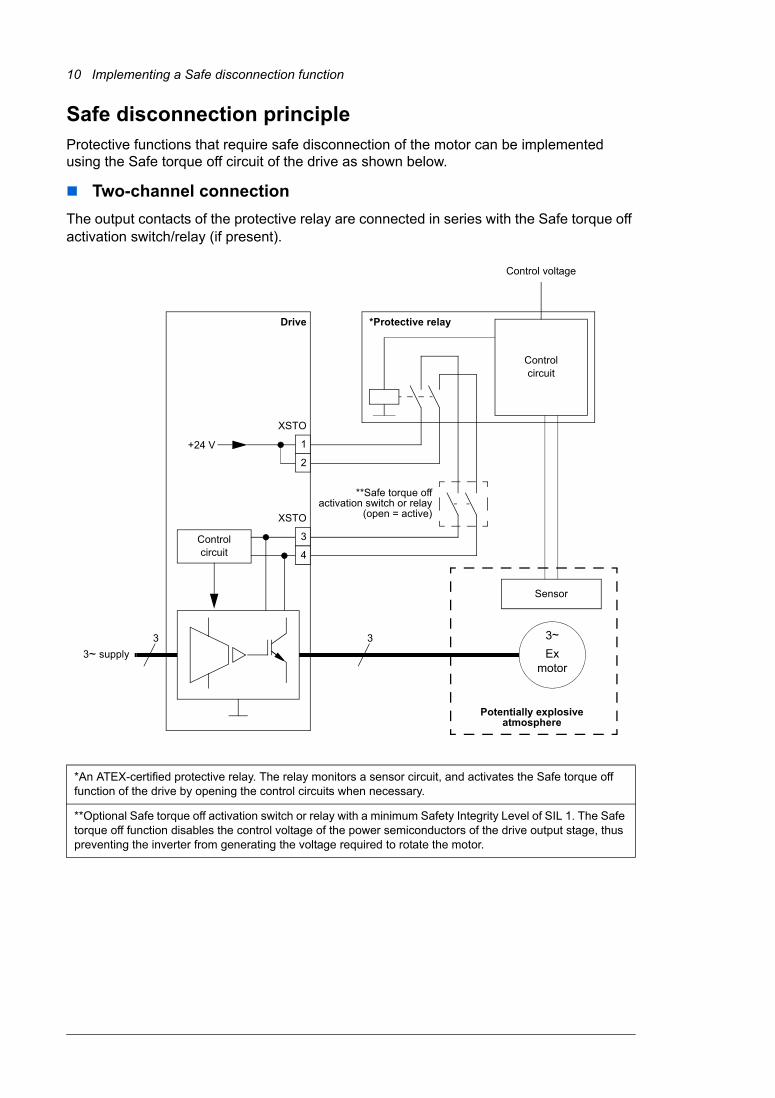
Safe disconnection principleProtective functions that require safe disconnection of the motor can be implemented using the Safe torque off circuit of the drive as shown below.
Two-channel connectionThe output contacts of the protective relay are connected in series with the Safe torque off activation switch/relay (if present).
*An ATEX-certified protective relay. The relay monitors a sensor circuit, and activates the Safe torque off function of the drive by opening the control circuits when necessary.
**Optional Safe torque off activation switch or relay with a minimum Safety Integrity Level of SIL 1. The Safe torque off function disables the control voltage of the power semiconductors of the drive output stage, thus preventing the inverter from generating the voltage required to rotate the motor.
+24 V
Control circuit
Drive
**Safe torque offactivation switch or relay
(open = active)
3 3 3~Ex
motor3~ supply
*Protective relay
Control circuit
Control voltage
Sensor
Potentially explosive atmosphere
XSTO
XSTO
1
2
3
4
Implementing a Safe disconnection function 11
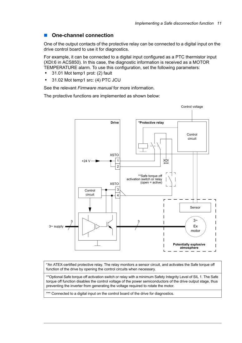
One-channel connectionOne of the output contacts of the protective relay can be connected to a digital input on the drive control board to use it for diagnostics.
For example, it can be connected to a digital input configured as a PTC thermistor input (XDI:6 in ACS850). In this case, the diagnostic information is received as a MOTOR TEMPERATURE alarm. To use this configuration, set the following parameters:• 31.01 Mot temp1 prot: (2) fault• 31.02 Mot temp1 src: (4) PTC JCU
See the relevant Firmware manual for more information.
The protective functions are implemented as shown below:
*An ATEX-certified protective relay. The relay monitors a sensor circuit, and activates the Safe torque off function of the drive by opening the control circuits when necessary.
**Optional Safe torque off activation switch or relay with a minimum Safety Integrity Level of SIL 1. The Safe torque off function disables the control voltage of the power semiconductors of the drive output stage, thus preventing the inverter from generating the voltage required to rotate the motor.
*** Connected to a digital input on the control board of the drive for diagnostics.
+24 V
Control circuit
Drive
**Safe torque offactivation switch or relay
(open = active)
3 3 3~Ex
motor3~ supply
*Protective relay
Control circuit
Control voltage
Sensor
Potentially explosive atmosphere
XSTO
XSTO
1
2
3
4
***XDI
12 Implementing a Safe disconnection function
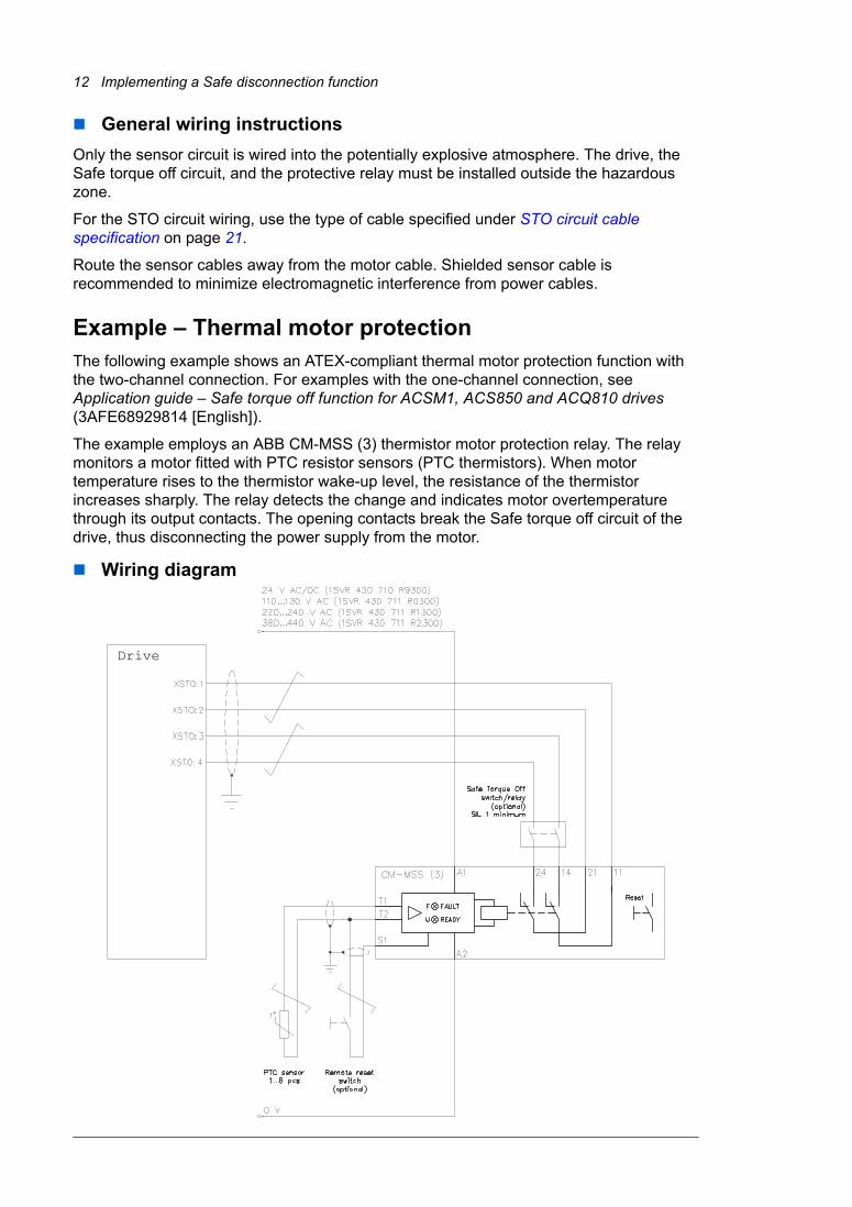
General wiring instructionsOnly the sensor circuit is wired into the potentially explosive atmosphere. The drive, the Safe torque off circuit, and the protective relay must be installed outside the hazardous zone.
For the STO circuit wiring, use the type of cable specified under STO circuit cable specification on page 21.
Route the sensor cables away from the motor cable. Shielded sensor cable is recommended to minimize electromagnetic interference from power cables.
Example – Thermal motor protectionThe following example shows an ATEX-compliant thermal motor protection function with the two-channel connection. For examples with the one-channel connection, see Application guide – Safe torque off function for ACSM1, ACS850 and ACQ810 drives (3AFE68929814 [English]).
The example employs an ABB CM-MSS (3) thermistor motor protection relay. The relay monitors a motor fitted with PTC resistor sensors (PTC thermistors). When motor temperature rises to the thermistor wake-up level, the resistance of the thermistor increases sharply. The relay detects the change and indicates motor overtemperature through its output contacts. The opening contacts break the Safe torque off circuit of the drive, thus disconnecting the power supply from the motor.
Wiring diagram
Drive
Implementing a Safe disconnection function 13
Thermistor motor protection relay specificationThe order codes of CM-MSS (3) relays for different control voltages are listed below.
For technical data of the relays, see page 21. More information on the CM-MSS series of relays is available from Electronic products and relays - Technical catalogue (2CDC110004C0206).
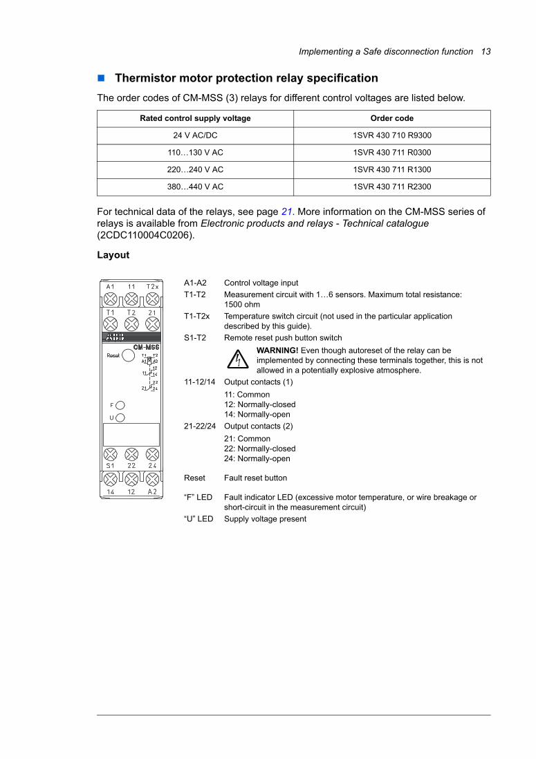
Layout
Rated control supply voltage Order code
24 V AC/DC 1SVR 430 710 R9300
110…130 V AC 1SVR 430 711 R0300
220…240 V AC 1SVR 430 711 R1300
380…440 V AC 1SVR 430 711 R2300
A1-A2 Control voltage inputT1-T2 Measurement circuit with 1…6 sensors. Maximum total resistance:
1500 ohmT1-T2x Temperature switch circuit (not used in the particular application
described by this guide).S1-T2 Remote reset push button switch
WARNING! Even though autoreset of the relay can be implemented by connecting these terminals together, this is not allowed in a potentially explosive atmosphere.
11-12/14 Output contacts (1)11: Common12: Normally-closed14: Normally-open
21-22/24 Output contacts (2)21: Common22: Normally-closed24: Normally-open
Reset Fault reset button
“F” LED Fault indicator LED (excessive motor temperature, or wire breakage or short-circuit in the measurement circuit)
“U” LED Supply voltage present
14 Implementing a Safe disconnection function
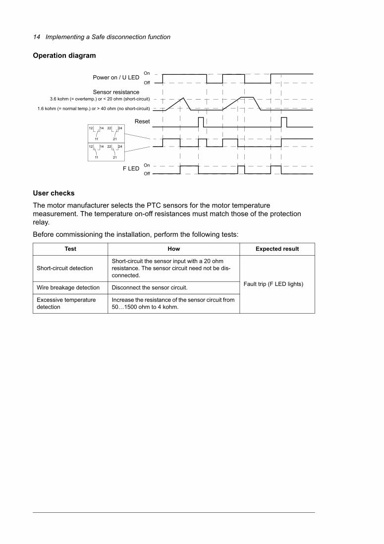
Operation diagram
User checksThe motor manufacturer selects the PTC sensors for the motor temperature measurement. The temperature on-off resistances must match those of the protection relay.
Before commissioning the installation, perform the following tests:
Test How Expected result
Short-circuit detectionShort-circuit the sensor input with a 20 ohm resistance. The sensor circuit need not be dis-connected.
Fault trip (F LED lights)Wire breakage detection Disconnect the sensor circuit.
Excessive temperature detection
Increase the resistance of the sensor circuit from 50…1500 ohm to 4 kohm.
On
Off
3.6 kohm (= overtemp.) or < 20 ohm (short-circuit)
1.6 kohm (= normal temp.) or > 40 ohm (no short-circuit)
On
Off
Power on / U LED
Sensor resistance
Reset
F LED
11
12 14
21
22 24
11
12 14
21
22 24
Technical data 15
3
Technical data
Applicable standardsThe ATEX-certified Safe disconnection function of the drive complies with the standards listed below.
EN 50495: 2010 Safety devices required for the safe functioning of equipment with respect to explosion risks
IEC 61508 Part 1: 1998 - General RequirementsPart 2: 2000 - Requirements for electrical/electronic/programmable electronic safety-related systems
EN 61800-5-2: 2007 Adjustable speed electrical power drive systemsPart 5-2: Safety requirements - Functional
16 Technical data
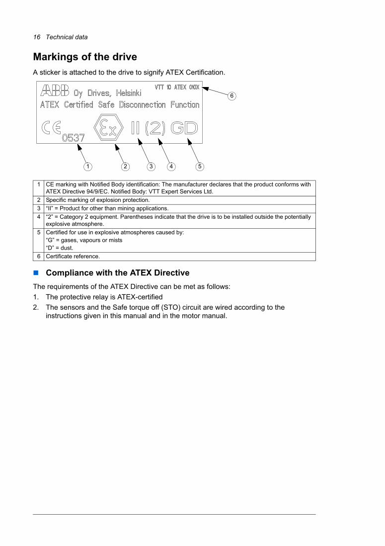
Markings of the driveA sticker is attached to the drive to signify ATEX Certification.
Compliance with the ATEX DirectiveThe requirements of the ATEX Directive can be met as follows:1. The protective relay is ATEX-certified2. The sensors and the Safe torque off (STO) circuit are wired according to the
instructions given in this manual and in the motor manual.
1 CE marking with Notified Body identification: The manufacturer declares that the product conforms with ATEX Directive 94/9/EC. Notified Body: VTT Expert Services Ltd.
2 Specific marking of explosion protection.3 “II” = Product for other than mining applications.4 “2” = Category 2 equipment. Parentheses indicate that the drive is to be installed outside the potentially
explosive atmosphere.5 Certified for use in explosive atmospheres caused by:
“G” = gases, vapours or mists“D” = dust.
6 Certificate reference.
1 2 3 4 5
6
Technical data 17
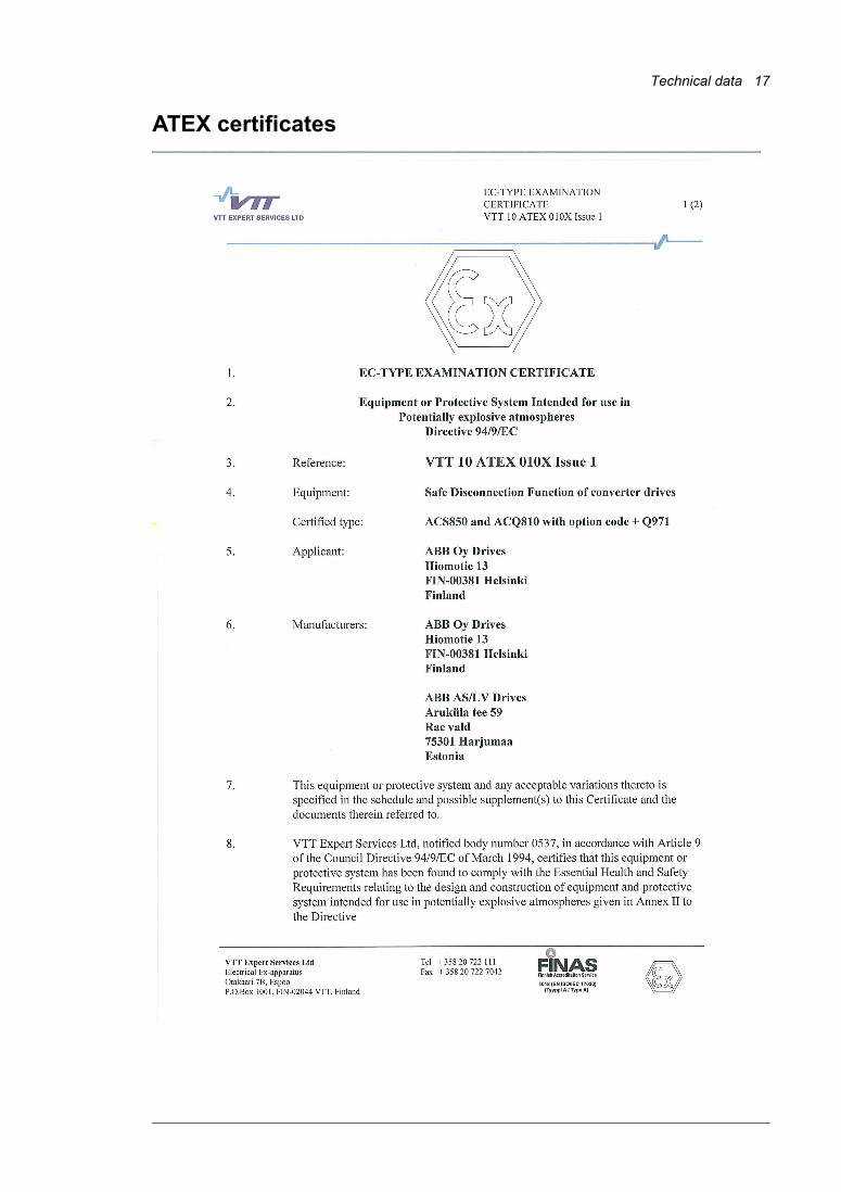
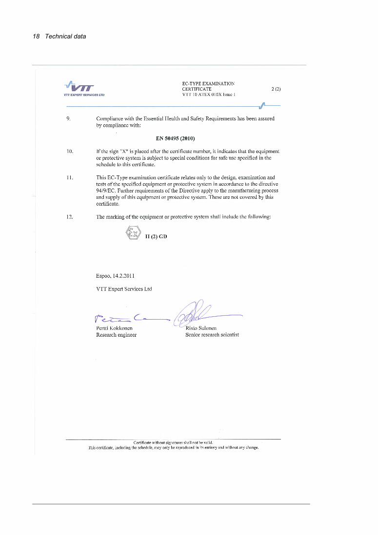
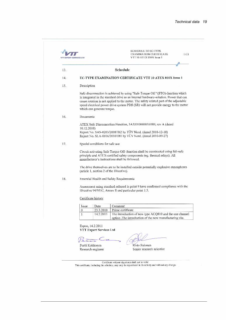
ATEX certificates
18 Technical data
Technical data 19
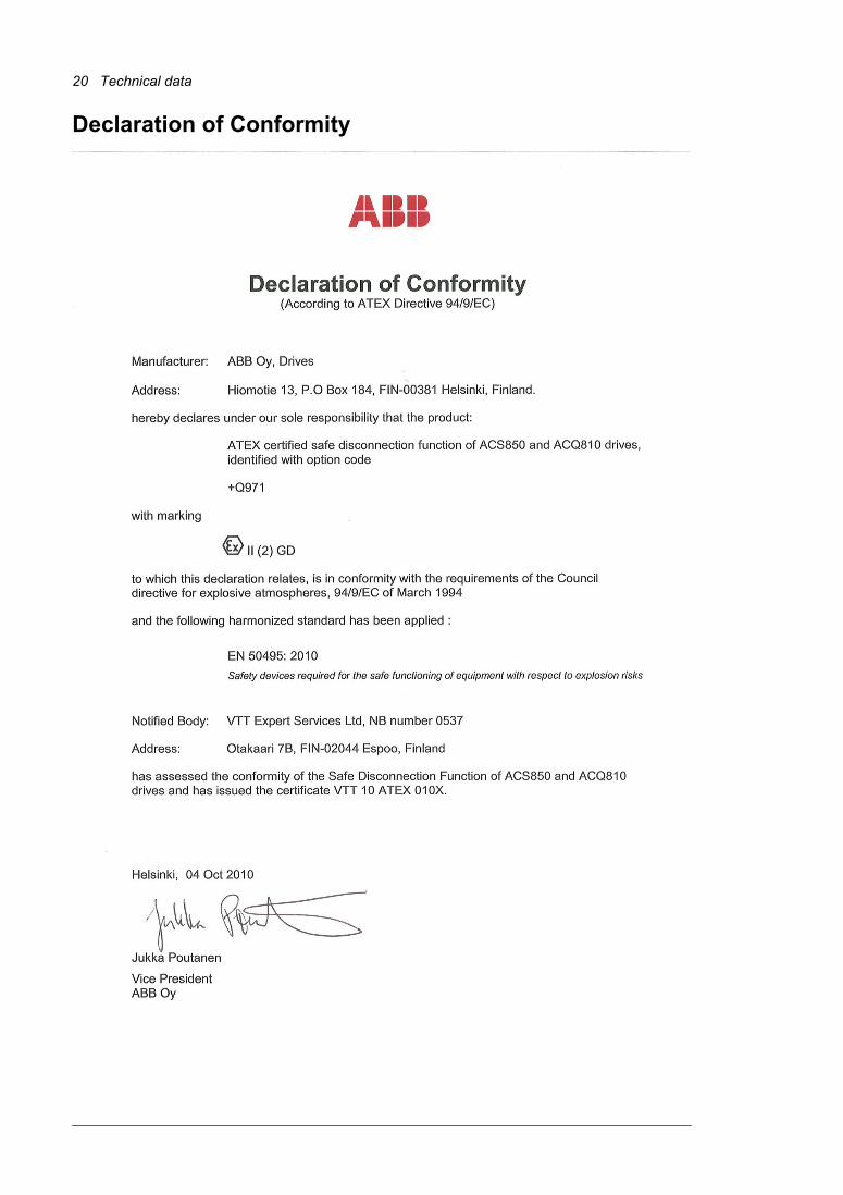
20 Technical data
Declaration of Conformity
Technical data 21
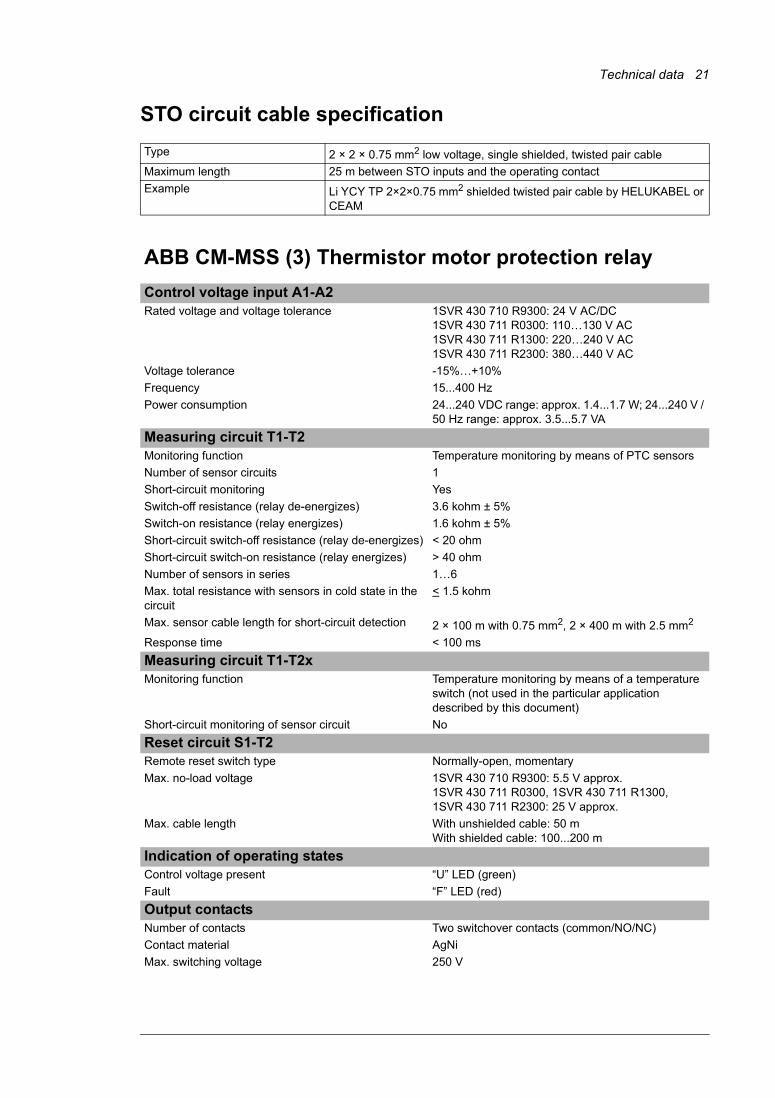
STO circuit cable specificationType 2 × 2 × 0.75 mm2 low voltage, single shielded, twisted pair cableMaximum length 25 m between STO inputs and the operating contactExample Li YCY TP 2×2×0.75 mm2 shielded twisted pair cable by HELUKABEL or
CEAM
ABB CM-MSS (3) Thermistor motor protection relayControl voltage input A1-A2Rated voltage and voltage tolerance 1SVR 430 710 R9300: 24 V AC/DC
1SVR 430 711 R0300: 110…130 V AC1SVR 430 711 R1300: 220…240 V AC1SVR 430 711 R2300: 380…440 V AC
Voltage tolerance -15%…+10%Frequency 15...400 HzPower consumption 24...240 VDC range: approx. 1.4...1.7 W; 24...240 V /
50 Hz range: approx. 3.5...5.7 VA Measuring circuit T1-T2Monitoring function Temperature monitoring by means of PTC sensorsNumber of sensor circuits 1Short-circuit monitoring YesSwitch-off resistance (relay de-energizes) 3.6 kohm ± 5%Switch-on resistance (relay energizes) 1.6 kohm ± 5%Short-circuit switch-off resistance (relay de-energizes) < 20 ohmShort-circuit switch-on resistance (relay energizes) > 40 ohmNumber of sensors in series 1…6Max. total resistance with sensors in cold state in the circuit
< 1.5 kohm
Max. sensor cable length for short-circuit detection 2 × 100 m with 0.75 mm2, 2 × 400 m with 2.5 mm2
Response time < 100 msMeasuring circuit T1-T2xMonitoring function Temperature monitoring by means of a temperature
switch (not used in the particular application described by this document)
Short-circuit monitoring of sensor circuit NoReset circuit S1-T2Remote reset switch type Normally-open, momentaryMax. no-load voltage 1SVR 430 710 R9300: 5.5 V approx.
1SVR 430 711 R0300, 1SVR 430 711 R1300, 1SVR 430 711 R2300: 25 V approx.
Max. cable length With unshielded cable: 50 mWith shielded cable: 100...200 m
Indication of operating statesControl voltage present “U” LED (green)Fault “F” LED (red)Output contactsNumber of contacts Two switchover contacts (common/NO/NC)Contact material AgNiMax. switching voltage 250 V
22 Technical data
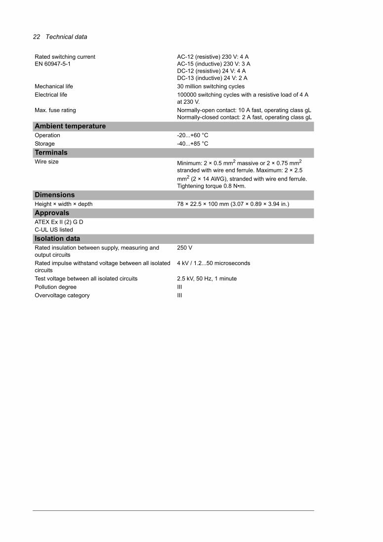
Rated switching current EN 60947-5-1
AC-12 (resistive) 230 V: 4 AAC-15 (inductive) 230 V: 3 ADC-12 (resistive) 24 V: 4 ADC-13 (inductive) 24 V: 2 A
Mechanical life 30 million switching cycles Electrical life 100000 switching cycles with a resistive load of 4 A
at 230 V.Max. fuse rating Normally-open contact: 10 A fast, operating class gL
Normally-closed contact: 2 A fast, operating class gLAmbient temperatureOperation -20...+60 °CStorage -40...+85 °CTerminalsWire size Minimum: 2 × 0.5 mm2 massive or 2 × 0.75 mm2
stranded with wire end ferrule. Maximum: 2 × 2.5 mm2 (2 × 14 AWG), stranded with wire end ferrule. Tightening torque 0.8 N•m.
DimensionsHeight × width × depth 78 × 22.5 × 100 mm (3.07 × 0.89 × 3.94 in.)ApprovalsATEX Ex II (2) G DC-UL US listedIsolation dataRated insulation between supply, measuring and output circuits
250 V
Rated impulse withstand voltage between all isolated circuits
4 kV / 1.2...50 microseconds
Test voltage between all isolated circuits 2.5 kV, 50 Hz, 1 minutePollution degree IIIOvervoltage category III
Further information
Product and service inquiriesAddress any inquiries about the product to your local ABB representative, quoting the type designation and serial number of the unit in question. A listing of ABB sales, support and service contacts can be found by navigating to www.abb.com/drives and selecting Sales, Support and Service network.
Product trainingFor information on ABB product training, navigate to www.abb.com/drives and select Training courses.
Providing feedback on ABB Drives manualsYour comments on our manuals are welcome. Go to www.abb.com/drives and select Document Library – Manuals feedback form (LV AC drives).
Document library on the InternetYou can find manuals and other product documents in PDF format on the Internet. Go to www.abb.com/drives and select Document Library. You can browse the library or enter selection criteria, for example a document code, in the search field.
3AU
A00
0007
4343
Rev
B E
N 2
011-
04-0
5Contact us
ABB OyDrivesP.O. Box 184FI-00381 HELSINKIFINLANDTelephone +358 10 22 11Fax +358 10 22 22681www.abb.com/drives
ABB Inc.Automation TechnologiesDrives & Motors16250 West Glendale DriveNew Berlin, WI 53151USATelephone 262 785-3200
1-800-HELP-365Fax 262 780-5135www.abb.com/drives
ABB Beijing Drive Systems Co. Ltd.No. 1, Block D, A-10 Jiuxianqiao BeiluChaoyang DistrictBeijing, P.R. China, 100015Telephone +86 10 5821 7788Fax +86 10 5821 7618www.abb.com/drives