Embed Size (px)
Citation preview

CommerCiaL fire-rated WiringsystemsTHERMAL MANAGEMENT SOLUTIONS WWW.PENTAIRTHERMAL.COMEN-CommercialFireRatedSpecialtyWiringCatalog-SB-H57513 11/13THERMAL MANAGEMENT SOLUTIONS
NORTH AMERICA Tel: +1.800.545.6258Fax: +1.800.527.5703Tel: +1.650.216.1526Fax: [email protected]
EuROpE, MIddlE EAsT, AfRICATel: +32.16.213.511Fax: [email protected]
AsIA pACIfICTel: +86.21.2412.1688Fax: [email protected]
lATIN AMERICATel: +1.713.868.4800Fax: [email protected]
Pentair, DigiTrace, Handvise, Pyropak, PyroSizer, Pyrotenax, QuickTerm, Sheathmaster, System 1850, and System 1850-SE are owned by Pentair or its global affiliates. All other trademarks are the property of their respective owners. Pentair reserves the right to change specifications without prior notice.
© 2004-2013 Pentair.
WWW.pENTAIRTHERMAl.COM
NO
RTH
AMER
ICA 2013com
mercial Fire-rated W
iring systems

For over 75 years, Pyrotenax brand mineral insulated products have satisfied the unique requirements of the wiring and heating industries.
Pentair Thermal Management offers a unique product—Pyrotenax brand Mineral Insulated (MI) wiring cable—for the safe operation of critical emergency circuits. These circuits are essential for the safe evacuation of buildings and to continue firefighters’ efforts during an emergency. Typical fire-rated applications include wiring for fire pumps, emergency generators, firefighters’ elevators and smoke extraction fans.
Other applications include the retrofitting of electrical power feeders in commercial buildings due to increased power consumption and the elimination of the effects of electromagnetic interference (caused by high current feeders) on electronic equipment.
We provide quality solutions for winter safety, comfort and performance to building and infrastructure design, construction, operation and maintenance professionals. From pipe freeze protection to maintaining fluid temperatures and melting snow, detecting leaks, heating floors, maintaining critical circuits with fire-rated and specialty cables, you can rely on Pentair Thermal Managements’ solutions & services for greater safety, comfort and performance.
the heart of our solutions
building & infrastructure solutions

iFloorheating icommercial fire-rated wiring
Tunnels
Airports
Hospitals
High-rise buildings
High-rise buildings, hospitals, airports, and tunnels are locations where fires can be costly and deadly if the emergency systems in place do not operate properly. Pentair Thermal Management fire-rated cables will operate for at least 2 hours under fire conditions to allow for the continued operation of life safety equipment and the safe evacuation of the facility.
Mineral Insulated cable technology for special applications include hollow conductor cable systems for high current particle accelerator applica-tions, patented systems for eliminating electromagnetic interference, and systems for introducing utility services into a building using MI cable instead of concrete encasement of the service conductors. Historic and commercial building retrofits are typical applications where the space for electrical wiring is limited. Pentair Thermal Management non-fire-rated cables and service entrance systems are small in profile and unobtrusive, providing the perfect solution for these applications.
Pentair Thermal Management wiring systems can be found in commercial applications worldwide:
Rockefeller Center, USA • Riyadh University Hospital, Saudi Arabia • U.S. Capitol Building, USA • Stuttgart International Airport, Germany • NYC Mu-seum of Natural History, USA • Heathrow International Airport, UK • Harvard University, USA • NYU Medical Center, USA • Montreal Metro, CA • Brussels Metro, Belgium • Pentagon Building, USA • Wing Lung Bank, Hong Kong • Yankee Stadium, USA • Buckingham Palace, UK • The White House, USA • Vienna Metro, Austria • Texas Medical Center, USA • Dublin Airport, Ireland • Los Angeles City Hall, USA • Channel Tunnel, UK
specialty wiring systems
fire-rated systems

ii PENTAIRii THERMAL MANAGEMENT SOLUTIONS
APPLICATIoNS
Fire pump
Main electrical panel
Central fire alarm control panel
Smoke extraction fans Firefighters’ elevatorPressurization fans
Utilitytransformer
Generator
Feeder panel

power cables
fire alarm cables
For all critical life safety circuits fed by the emergency supply including: the fire pump, fire alarm system, smoke extraction fans, pressurization fans, and power for the firefighters’ elevator.
For the retrofit of service entrance feeders when additional power is needed and where encasement of conventional conductors in concrete is not feasible.
For the retrofitting of power feeders in locations where space is limited and difficult installation conditions exist.
Standard power feeders throughout the building.
fire-rated cable system
service entrance cable system
space saving cable system
normal power cables
typical wiring systems in a high-rise building
Fire-RatedCable System
Space SavingCable System
Service Entrance Cable System
Technical Data Sheets
Codes and Standards
Appendixes

iv PENTAIRiv THERMAL MANAGEMENT SOLUTIONS
pyrotenaX system 1850A UL Classified/ ULC Listed 2-hour fire-rated, mineral insulated, copper-sheathed power cable for protection of critical life safety circuits.
pyrotenaX system 1850Pyrotenax System 1850 mineral insulated, copper-sheathed wiring cable is an ideal alternative for retrofitting feeders in buildings and for ease of installa-tion in tight spaces and difficult runs.
Space saving MI cable vs conduit & wire
WIRING SYSTeMS
fire-rated cable system
space saving cable system

vFloorheating vcommercial fire-rated wiring
pyrotenaX system 1850-seA UL Classified 2-hour fire-rated, mineral insulated, copper-sheathed service entrance cable system that allows service entrance conductors to be routed inside the building.
This system is designed as an alternative to concrete encasement for service conductors. Where conditions make concrete encasement difficult or imprac-tical, Authorities Having Jurisdiction (AHJs) have accepted this system as an alternative to concrete encasement.
service entrance system

vi PENTAIRvi THERMAL MANAGEMENT SOLUTIONS
Seamlessmetal sheath
Magnesiumoxide insulation
Solid conductors
Using only inorganic materials, copper and magnesium oxide (Mgo), Pyrotenax Mineral Insulated (MI) wiring cable offers a unique combination of dependability, versatility, and performance. Highly compacted magnesium oxide insulation provides exceptional temperature and electrical performance. Manufactured using a process unique to the Pyrotenax brand, this product has set the standard for fire-rated electrical cables worldwide.
Pyrotenax mineral insulated cable is listed in the NeC/CeC as “Type MI” and is available in 1, 2, 3, 4 and 7 conductor configurations in a range of sizes between 18 AWG and 500 kcmil.
Pyrotenax mineral insulated wiring cable offers unique fire survival properties as well as small size and enhanced ampacity capability.
Designed to specified length tolerances, Pyrotenax MI factory terminated cables are ideal for a wide variety of wiring applications including hazardous locations and areas where the space for electrical wiring is limited.
WIRING TeCHNoLoGY
mineral insulated technology

viiFloorheating viicommercial fire-rated wiring
Thic
knes
s (I
n.)
Thic
knes
s (m
m)
Fire resistance (W)
0.5 0.75 1 2
2
3
3
4
4
5
5
6 152
7
76
101
127
178
Thic
knes
s (I
n.)
Thic
knes
s (m
m)
Fire resistance (W)
0.5 0.75 1 2
2
3
3
4
4
5
5
6 152
7
76
101
127
178
Thic
knes
s (I
n.)
Thic
knes
s (m
m)
Fire resistance (hr)
0.5 0.75 1 2
2
3
3
4
4
5
5
6 152
7
76
101
127
178
4 inches of concrete minimum for 2-hour fire resistance of a concrete slab
Dotted line: regular aggregates
Solid line: lightweight aggregates
The traditional method of fire protection of electrical cables in emergency circuits (encasement of non-fire-rated cables in 2 inches of concrete) was accepted as suitable for 1-hour protection, but is hardly adequate for today’s 2-hour requirement. encasement of cables in concrete is not a listed method, and in fact Fig 19.2.7 (reproduced below) in the 2008 NFPA Fire Protection Handbook clearly shows that it is not suitable. Codes will eventually change to reflect this reality, but it will take time—meanwhile, designers be aware!
PYRoTeNAx MI CABLe
Fire-rated electrical cables are UL Classified/ULC Listed as 2-hour fire-rated if they successfully pass the ANSI/UL 2196 and ULC-S139 fire test standards, which require that circuit integrity be maintained throughout a fire test that reaches 1850°F over a two hour period, followed by the full force of a fire-fighter's hose-stream.
In 2012, Underwriters Laboratories conducted research testing on polymer-insulated fire-rated cables and found serious problems with the cable designs, so much so that based on that research they made a decision to de-certify all fire-rated cables. MI cable, being a different technology and not subject to the issues with polymer cables was quickly re-instated by UL and ULC with a new System identifier ("System 1850") in UL/ULC categories FHIT/FHITC.
You can trust Pyrotenax fire-rated cable, the original, and the best solution for protection of life safety circuits. The totally inorganic construction of unjacketed System 1850 MI cable allows for an environmentally clean electrical cable that does not burn, produce smoke, or contribute fuel when exposed to fire conditions.
the benchmark of safety and reliability
FM Approvals GP-12-Hour Fire Resistant Cable

viii PENTAIRviii THERMAL MANAGEMENT SOLUTIONS
FeATUReS
system 1850 system 1850-se
2-hour fire rated • •
No conduit required • •
Zero smoke, zero flame spread • •
Vertical strength in fire • •
Space savings • •
Free air ampacity • •
One pull system •
30-year extended warranty • •
Wet location • •
Fire-rated spliced available • N/A
benefits
N/A = Not Applicable

ixFloorheating ixcommercial fire-rated wiring
500 kcmil THHN cable in conduit rated at
380 A
500 kcmil MI cable rated at
620 A
ReASoNS To CHooSe PeNTAIR THeRMALMANAGeMeNT WIRING SYSTeMS
It is critical that circuits involving life safety and firefighting efforts remain operable during an emergency. These circuits provide power for emergency equipment, fire pumps, pressurization fans and fire alarm systems. Pyrotenax fire-rated cables are designed to operate for at least 2 hours under fire conditions to allow for the continued operation of life safety equipment and the safe evacuation of the facility.
Single conductor Pyrotenax MI cables require no conduit, allowing for as much as 80% space savings over conduit and wire. In addition, the NeC and CeC allow bundled single-conductor MI cable to be operated at higher ampacities, resulting in significant savings in materials and installation costs, especially in short runs.
The inorganic construction of Pyrotenax MI wiring cables means that there is virtually no aging of the cable. This allows Pyrotenax MI wiring cables to operate at higher ampacities than conventional wiring, resulting in significant cost savings in materials and installation (especially in shorter runs).
fire rated
free air rating
single conductor advantages

x PENTAIRx THERMAL MANAGEMENT SOLUTIONS
xiFloorheating xicommercial fire-rated wiring
iso certification Pentair Thermal Management maintains an ISO 9001:2008 registered Quality Management System and 14001:2004 Environmental Management Systems at its MI cable manufacturing facility. The Quality Management System covers all manufacturing and business processes and the Environmental Management Systems ensures sound environmental performance.
six sigma Understanding and satisfying the needs of our customers is important to Pentair Thermal Management. We have a customer-focused, data-driven Six Sigma program to continuously improve the quality and delivery of our products, services, and business processes.
on time delivery Pentair Thermal Management consistently meets customer demands for product delivery. We strive to ship product from stock on the day the order is placed and for 100% on time delivery of all custom manufactured products.
SeRVICeS AND SUPPoRT
With years of experience, Pentair Thermal Management field service engineers are highly qualified to offer field support, advice, and training at all stages of a project. Backed by expert factory engineering support, the service is available worldwide.
Pentair Thermal Management has been at the forefront in the development of life safety wiring systems for many years. our engineering expertise is frequently called upon to consult on critical applications, create technical product standards and to revise national and local codes. our specialists can help you with your specification needs as well.
The construction of Pyrotenax MI wiring cable lends itself to a variety of applications that would be difficult or impossible to solve otherwise. examples include using the MI cable sheath and a compensator to eliminate magnetic fields around the MI cables, as well as using hollow conductors to allow circulation of coolant to limit temperature rise at high current densities in particle accelerator applications.
field and technical support
eXpertise in life safety circuits
unique solutions
ISO 14001Environmental

xii PENTAIRxii THERMAL MANAGEMENT SOLUTIONS
WeB SeRVICeS AND SoFTWARe
Pentair Thermal Management is a world leader in heat-tracing, fire-rated and specialty wiring and sensing solutions for the oil & gas, power, food & beverage, chemical, water and other process industries, as well as for the commercial and residential construction markets. Visit our web site to download, print, browse product information, or submit a question.
on our interactive frequently asked questions and answers (FAQ) page, you’ll find questions broken down by markets and product lines. If your question does not appear, simply submit a new question. A Pentair Thermal Management technical expert will answer your question and post it to the web site.
The online voltage drop calculator allows you to estimate the voltage drop for Pyrotenax MI cable, and to determine the appropriate size of cable to use.
pyrosizer software aids in the design of critical circuits that utilize Pyrotenax MI copper cable. enter basic project conditions on the “Project Default Parameters” screen and then simply apply these parameters to the entire project to minimize keying, and speed up design.
visit www.pentairthermal.com
on-line design tool
download cable sizing software
on-line technical support

xiiiFloorheating xiiicommercial fire-rated wiring
Visit our web site at www.pentairthermal.com or contact us at 1-800-545-6258.
for proven fire-rated solutions, look to the leader.
pentair thermal management north american operations
Menlo Park, CARedwood City, CA
Trenton, Ontario
Baton Rouge, LAHouston, TX
Worldwide Headquarters
Edmonton, Alberta
Fort McMurray, Alberta
Philadelphia, PA
HeadquartersService/Sales CentersManufacturing Centers
Chicago, IL
Seattle, WA
Milton, Ontario
before you buy, weigh the facts:
greater selection
offering the most complete product line of proven heating technologies to better satisfy your unique needs.
more innovation
As a world leader in heating cable technologies, design optimization, construction, and control and monitoring systems, we invented many of today’s industry standards.
more manufacturing experience
Quality-driven manufacturing processes, combined with years of manufacturing self-regulating and mineral-insulated cables gives you products proven to be the most reliable.


Fire-Rated Cable
SystemSpace Saving Cable System
Service Entrance Cable System
Codes and StandardsTechnical D
ata SheetsAppendixes
This section provides design guides for the Pentair Thermal Management commercial wiring products. Each design guide is also available in .pdf format on our web site at www.pentairthermal.com.
Contents
System 1850 Fire-Rated Cable System . . . . . . . . . . . . . . . . . . . . . . . . . . . . . . . . . . . . . 3
Space Saving Cable System . . . . . . . . . . . . . . . . . . . . . . . . . . . . . . . . . . . . . . . . . . . . . 19
System 1850-SE Service Entrance Cable System . . . . . . . . . . . . . . . . . . . . . . . . . . . . 31
Design guiDes
1 tHeRMAL MAnAGeMent soLUtIons

THERMAL MANAGEMENT SOLUTIONS2

Fire-Rated Cable
SystemSpace Saving Cable System
Service Entrance Cable System
sCodes and Standards
Technical Data Sheets
Appendixes
This section provides an overview of general circuit design considerations and installation guidelines for Pyrotenax Fire-Rated Cables. For additional information, contact your Pentair Thermal Management representative or phone Pentair Thermal Management at (800) 545-6258. Also, visit our web site at www.pentairthermal.com.
Contents
Introduction . . . . . . . . . . . . . . . . . . . . . . . . . . . . . . . . . . . . . . . . . . . . . . . . . . . . . . . . . . . 4Typical Applications . . . . . . . . . . . . . . . . . . . . . . . . . . . . . . . . . . . . . . . . . . . . . . . . 4Typical Locations . . . . . . . . . . . . . . . . . . . . . . . . . . . . . . . . . . . . . . . . . . . . . . . . . . 4Pyrotenax System 1850 Fire-Rated Mineral Insulated Cable . . . . . . . . . . . . . . . 4
Cable Construction . . . . . . . . . . . . . . . . . . . . . . . . . . . . . . . . . . . . . . . . . . . . . . 5Configurations . . . . . . . . . . . . . . . . . . . . . . . . . . . . . . . . . . . . . . . . . . . . . . . . . . 5
Approvals and Certifications . . . . . . . . . . . . . . . . . . . . . . . . . . . . . . . . . . . . . . . . . 5Pyrotenax System 1850 MI Cable . . . . . . . . . . . . . . . . . . . . . . . . . . . . . . . . . . . 5Outside North America . . . . . . . . . . . . . . . . . . . . . . . . . . . . . . . . . . . . . . . . . . . 5
Fire Alarm Circuits . . . . . . . . . . . . . . . . . . . . . . . . . . . . . . . . . . . . . . . . . . . . . . . . . . . . . 6Pyrotenax System 1850 Fire Alarm Circuit Design Considerations . . . . . . . . . . 6
Cable Sizing . . . . . . . . . . . . . . . . . . . . . . . . . . . . . . . . . . . . . . . . . . . . . . . . . . . . 6Cable Termination and Splices . . . . . . . . . . . . . . . . . . . . . . . . . . . . . . . . . . . . . 6
Installation Guidelines . . . . . . . . . . . . . . . . . . . . . . . . . . . . . . . . . . . . . . . . . . . . . . 7Supporting Fire Alarm Cable . . . . . . . . . . . . . . . . . . . . . . . . . . . . . . . . . . . . . . 7Seismic Considerations . . . . . . . . . . . . . . . . . . . . . . . . . . . . . . . . . . . . . . . . . . . 8Terminating Fire Alarm Cable . . . . . . . . . . . . . . . . . . . . . . . . . . . . . . . . . . . . . 8Connecting Fire Alarm Cable . . . . . . . . . . . . . . . . . . . . . . . . . . . . . . . . . . . . . . 8
Critical Power Circuits . . . . . . . . . . . . . . . . . . . . . . . . . . . . . . . . . . . . . . . . . . . . . . . . . . 9Circuit Design Considerations . . . . . . . . . . . . . . . . . . . . . . . . . . . . . . . . . . . . . . . . 9
Cable Sizing . . . . . . . . . . . . . . . . . . . . . . . . . . . . . . . . . . . . . . . . . . . . . . . . . . . . 9Voltage Drop . . . . . . . . . . . . . . . . . . . . . . . . . . . . . . . . . . . . . . . . . . . . . . . . . . . 10Equipment Bonding . . . . . . . . . . . . . . . . . . . . . . . . . . . . . . . . . . . . . . . . . . . . . 10Short Circuit Capability . . . . . . . . . . . . . . . . . . . . . . . . . . . . . . . . . . . . . . . . . . 11Expansion and Vibration . . . . . . . . . . . . . . . . . . . . . . . . . . . . . . . . . . . . . . . . . 11Corrosion and Copper-Armored Cables . . . . . . . . . . . . . . . . . . . . . . . . . . . . 11Cable Termination and Splices . . . . . . . . . . . . . . . . . . . . . . . . . . . . . . . . . . . . 11Typical System Installation . . . . . . . . . . . . . . . . . . . . . . . . . . . . . . . . . . . . . . 13
Installation Guidelines . . . . . . . . . . . . . . . . . . . . . . . . . . . . . . . . . . . . . . . . . . . . . 13Supporting System 1850 MI Cable . . . . . . . . . . . . . . . . . . . . . . . . . . . . . . . . . 13Seismic Considerations . . . . . . . . . . . . . . . . . . . . . . . . . . . . . . . . . . . . . . . . . . 14Cable Layout . . . . . . . . . . . . . . . . . . . . . . . . . . . . . . . . . . . . . . . . . . . . . . . . . . 15Terminating System 1850 MI Cable . . . . . . . . . . . . . . . . . . . . . . . . . . . . . . . . 16Connecting System 1850 MI Cable . . . . . . . . . . . . . . . . . . . . . . . . . . . . . . . . . 16
3 THERMAL MANAGEMENT SOLUTIONS EN-PyrotenaxSystem1850FireRatedCableSystem-DG-H57573 11/13
SYSTEM 1850 FIRE-RATED CABLE SYSTEM
IntRodUCtIon
Pentair Thermal Management Pyrotenax System 1850 mineral insulated (MI) wiring cables meet the relevant requirements of the U.S. National Electrical Code (NEC), the National Fire Alarm Code, the Canadian Electrical Code (CEC), and the Canadian National Building Code for fire protection of emergency power feeders and fire alarm circuits. The codes stipulate that a reliable source of power is required to operate all critical life safety circuits necessary to provide time for a safe evacuation of building occupants and to allow emergency crews to effectively control the fire. Fire-resistance ratings of 1-hour or 2-hours are required depending on national and local codes, the type of circuit, and the environment.
typical Applications
Pentair Thermal Management fire-rated wiring cables meet the most stringent requirements for 2-hour fire rating, allowing for the highest degree of fire protection for emergency back-up power supply systems, emergency equipment, and fire alarm systems. In the event of a fire, electrical power and communication is preserved for critical life safety circuits. These critical circuits provide power for:
• Fire pumps – to maintain pressure in the sprinkler system
• Firefighters’ elevators
• Smoke dampers and pressurization fans – to maintain smoke-free areas for egress
• Smoke extraction fans
• Emergency lighting and exit signs
• Fire alarm and voice communication systems
typical Locations
Typical locations requiring emergency power feeders include:
• High-rise buildings
• Hospitals and other institutions
• Historic buildings
• Tunnels and subways
• Airports, stadiums, hotels, banks, etc.
Pyrotenax system 1850 Fire-Rated Mineral Insulated Cable
System 1850 2-hour fire-rated MI cable offers a unique combination of dependability, versatility, and permanence while withstanding continuous operating temperatures as high as 250°C (482°F) and intermittent exposure temperatures as high as 1010°C (1850°F).
Featuring “zero smoke, zero flame spread, zero fuel contribution” and up to 80% space savings compared to conventional conduit and wire systems, System 1850 MI cable is the preferred choice for many specifiers. The ease with which this tough cable can be pulled into difficult runs with tight corners makes it an ideal choice for many applications. System 1850 MI cable may be installed in virtually any location: outdoors, submersed, or buried with a protective over-jacket. The cable can be bent, twisted, or pulled, and can withstand mechanical abrasion while remaining fully functional.
System 1850 MI cable is 2-hour fire-rated to ANSI/UL 2196 / ULC-S139 fire test standards, which utilize the ASTM E-119 time-temperature curve. The test requires that cables remain operational after exposure to temperatures up to 1010°C (1850°F) for two hours followed by the full force of a firefighter’s hose stream. System 1850 MI cable passes this rigorous circuit integrity test without additional mechanical protection.
SYSTEM 1850 FIRE-RATED CABLE SYSTEM
THERMAL MANAGEMENT SOLUTIONSEN-PyrotenaxSystem1850FireRatedCableSystem-DG-H57573 11/134

Fire-Rated Cable
SystemSpace Saving Cable System
Service Entrance Cable System
sCodes and Standards
Technical Data Sheets
Appendixes
CAbLe ConstRUCtIon
Pyrotenax System 1850 MI cables are manufactured using only inorganic materials, copper and magnesium oxide. This construction is inherently tough, yet allows the cable to be bent and molded to fit into tight spaces. In addition, the totally inorganic construction of unjacketed System 1850 MI cable allows for an environmentally clean electrical cable that does not burn, produce smoke, or contribute fuel when exposed to fire conditions.
Solid copper conductors
Magnesium oxide (MgO) insulation
Seamless copper sheath
Fig. 1 system 1850 MI cable construction
For superior corrosion protection, an optional polymer jacket is available and is suitable for use in temperatures as low as –40°C (–40°F).
ConFIGURAtIons
System 1850 fire-rated MI cables are available in a range of sizes and conductor configurations for power feeders and in twisted pair configurations for fire alarm circuits.
Approvals and Certifications
PyRotenAx systeM 1850 MI CAbLe
Pyrotenax System 1850 MI cables meet the requirements of the circuit integrity fire test, ANSI/UL 2196 (ULC-S139 in Canada), and are UL Listed and CSA Certified in North America.
The details of this system appear in the online UL and ULC Fire Resistance Directories as Electrical Circuit Integrity System (FHIT and FHITC) System No. 1850. Mineral insulated wiring cables are also Classified by Factory Mutual (FM) as a 2-hour fire-resistive cable.
Factory terminated MI cable sets are approved for both nonhazardous locations and hazardous locations. For specific approval information, see the product data sheets in the Technical Data section.
oUtsIde noRtH AMeRICA
Pyrotenax fire-rated fire alarm and power cables are also available for use outside North America, and are LPCB certified to BS EN 60702-1, BS 6387 Categories C, W, and Z, BS EN 50267-2-1, BS EN 50200, BS 8434-2 and BS 5839-1 for standard and enhanced grades of cable. These products carry the CE Mark and are approved to local standards. Contact Pentair Thermal Management for information on our range of cables certified for use worldwide.
Introduction
5 THERMAL MANAGEMENT SOLUTIONS EN-PyrotenaxSystem1850FireRatedCableSystem-DG-H57573 11/13

FIRe ALARM CIRCUIts
The following general guidelines relate to the design and installation of fire alarm circuits utilizing Pyrotenax System 1850 MI cables.
Pyrotenax system 1850 Fire Alarm Circuit design Considerations
Fire alarm systems should only be designed by professionals familiar with generally accepted design practices. The information provided below relates specifically to designs using Pentair Thermal Management fire alarm cables and must be followed, along with all relevant local codes and standards, to ensure that the systems are designed properly. For additional information, contact your Pentair Thermal Management representative or phone Pentair Thermal Management at (800) 545-6258.
CAbLe sIzInG
Primarily data and signal communications, these circuits are low voltage and low current, utilizing 18 AWG and 16 AWG conductors.
Cable sizing should be in accordance with the fire alarm system manufacturers’ recommendations.
CAbLe teRMInAtIon And sPLICes
When using Pyrotenax System 1850 shielded twisted-pair cables, the drain wire is connected to the metallic inner shield. At each junction box, the drain wires are connected together, but not grounded; the shield drain wire is only grounded at one point in the circuit.
system 1850 MI Cable
System 1850 MI fire alarm cables are approved as a complete system only when used with the appropriate Pyrotenax termination and splice kits. The use of nonapproved components may compromise the reliability of the system and will invalidate approvals and warranties.
Brassgland
Pot
Fig. 2 system 1850 MI cable termination
SYSTEM 1850 FIRE-RATED CABLE SYSTEM
THERMAL MANAGEMENT SOLUTIONSEN-PyrotenaxSystem1850FireRatedCableSystem-DG-H57573 11/136

Fire-Rated Cable
SystemSpace Saving Cable System
Service Entrance Cable System
sCodes and Standards
Technical Data Sheets
Appendixes
Emergencysplitter
Transferswitch
CPU
Security console(Central alarm control facility)
Basement
BasementGround
1 st floor
2 nd floor
3 rd floor
4 th floor
5 th floor
6 th floor
7 th floor
8 th floor
9 th floor
n th floor
Data-gathering panels
First device on each floor(Pull station, horn, speaker, strobe)
Other devices
Roof
Fire-ratedcable
Fig. 3 typical fire alarm system
Installation Guidelines
These installation guidelines apply to Pyrotenax System 1850 MI cables only. When installing a system, refer to the requirements in the UL/ULC Fire Resistance Directory and the appropriate System 1850 data sheets, or installation instructions shipped with the product, and available on the Pentair Thermal Management web site at www.pentairthermal.com.
sUPPoRtInG FIRe ALARM CAbLe
It is important that all support components are made of appropriate materials, such as copper, steel, stainless steel, and concrete. Low melting point or combustible materials such as aluminum, brass, plastic, lead, wood, etc. are not acceptable.
system 1850 MI Cable
System 1850 MI cables may be directly mounted on noncombustible surfaces such as concrete or masonry, or supported by steel rod and channel (trapeze) systems. UL/ULC listing requirements for fire-rated cables stipulate support spacing at certain intervals; refer to the installation instructions shipped with the product and available on the Pentair Thermal Management web site, www.pentairthermal.com.
Fire Alarm Circuits
7 THERMAL MANAGEMENT SOLUTIONS EN-PyrotenaxSystem1850FireRatedCableSystem-DG-H57573 11/13
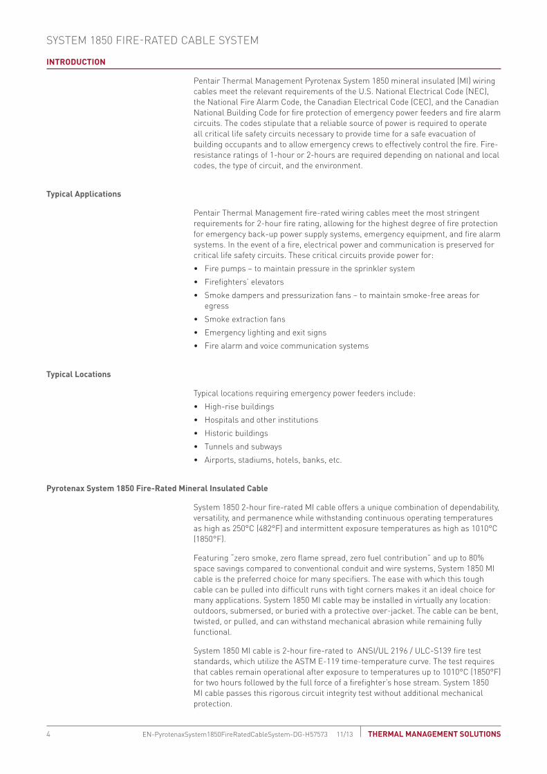
Trapeze method Surface-mounted installation
Steelrod
Steelchannel
Twisted paircables
Noncombustiblematerial
Twisted paircables
Fig. 4 typical fire alarm installations for system 1850 MI cable
seIsMIC ConsIdeRAtIons
In areas where there is a risk of seismic activity, precautions must be taken where the cable crosses expansion joints and at termination points. For more information, see Appendix: Pyrotenax MI Cable Expansion and Vibration (H57613).
teRMInAtInG FIRe ALARM CAbLe
Pyrotenax system 1850 MI cable
Details on terminating Pyrotenax System 1850 MI cables can be found in the installation instructions provided with each System 1850 MI fire alarm cable termination kit. Factory terminated System 1850 MI cable sets are available. For details on terminated cable sets, contact your Pentair Thermal Management representative or phone Pentair Thermal Management at (800) 545-6258.
ConneCtInG FIRe ALARM CAbLe
Pyrotenax system 1850 MI Cable
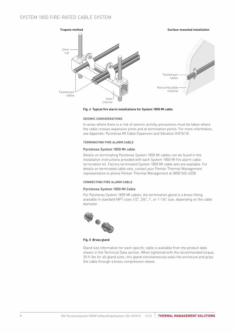
For Pyrotenax System 1850 MI cables, the termination gland is a brass fitting available in standard NPT sizes 1/2", 3/4", I", or 1-1/4" size, depending on the cable diameter.
Fig. 5 brass gland
Gland size information for each specific cable is available from the product data sheets in the Technical Data section. When tightened with the recommended torque, 25 ft-lbs for all gland sizes, this gland simultaneously seals the enclosure and grips the cable through a brass compression sleeve.
SYSTEM 1850 FIRE-RATED CABLE SYSTEM
THERMAL MANAGEMENT SOLUTIONSEN-PyrotenaxSystem1850FireRatedCableSystem-DG-H57573 11/138

Fire-Rated Cable
SystemSpace Saving Cable System
Service Entrance Cable System
sCodes and Standards
Technical Data Sheets
Appendixes
CRItICAL PoweR CIRCUIts
The following general guidelines relate to the design and installation of critical power circuits utilizing Pyrotenax System 1850 cables.
Circuit design Considerations
Critical power circuit systems should only be designed by professionals familiar with generally accepted design practices. The information provided below relates specifically to designs using Pyrotenax power cables and must be followed, along with all relevant local codes and standards, to ensure that the systems are designed properly. For further information, contact your Pentair Thermal Management representative or phone Pentair Thermal Management at (800) 545-6258.
CAbLe sIzInG
System 1850 MI cable size is based on circuit breaker size, which in turn is based on load calculations. Special rules apply for motors, including fire pumps, where cable size is based on 125% of full load current. Use the ampacity tables specified in the electrical code to determine the cable size. If the calculated voltage drop exceeds the specified limits, a larger cable size must be chosen.
Multiconductor MI cables have the same ampacity ratings as cable in conduit or other multiconductor cable types. However, the NEC and CEC allow full “free air” ampacity for unjacketed single conductor MI cables configured according to Fig. 6 as long as a space of 2.15 cable diameters is maintained between bundles.
(S)
(S)
MulticonductorMI cable
SingleconductorMI cables
Spacing (S) between multiphase paralleled single conductor cables
Note: For free air ampere ratings, the spacing “S” between bundles should be a minimum of 2.15 cable diameters in the U.S. (NEC) and Canada (CEC).
Fig. 6 spacing of bundled conductors
Although unjacketed single conductor MI cable is unaffected by any temperature increase resulting under the installation conditions shown in Fig. 6, the termination may need to be “sized-up” to keep it within its temperature limits in accordance with electrical code requirements. Refer to the installation instructions shipped with the product for details on sizing up MI cable terminations.
Critical Power Circuits
9 THERMAL MANAGEMENT SOLUTIONS EN-PyrotenaxSystem1850FireRatedCableSystem-DG-H57573 11/13

VoLtAGe dRoP
Voltage drop calculations are based on calculated load, not circuit breaker rating.
For conventional cables, simple formulas are used to determine if the cable size listed in the ampacity tables meets the required voltage drop limits. While these formulas can be applied to System 1850 MI cable, voltage drop values specific to the characteristics of MI cable can be calculated using any of the following:
• An equation based on the run length, the conductor current, and the circuit volt-age is provided in Appendix: Pyrotenax MI Voltage Drop Calculations (H57611)
• A quick voltage drop calculator is available on the Pentair Thermal Management web site, www.pentairthermal.com
• PyroSizer MI cable sizing software is available on the Pentair Thermal Manage-ment web site, www.pentairthermal.com, or through your Pentair Thermal Man-agement representative
eqUIPMent bondInG
The copper sheath of System 1850 MI cables meets North American code requirements for the equipment grounding conductor. The brass gland completes the grounding path from the cable sheath to the equipment. For single conductor cables, the ground path includes a nonferrous brass plate, as shown in Fig. 7 (in Canada, brass plates are required only for ampacities over 200 A).
MulticonductorMI cable
Brass glandBrass plate
Enclosure wall
Lock washer
Details of brass plate
Steel enclosure cutout(steel must be removed)
Lock washer
Single conductorMI cables
Locknuts
.Fig. 7 equipment bonding using brass plate
SYSTEM 1850 FIRE-RATED CABLE SYSTEM
THERMAL MANAGEMENT SOLUTIONSEN-PyrotenaxSystem1850FireRatedCableSystem-DG-H57573 11/1310
Fire-Rated Cable
SystemSpace Saving Cable System
Service Entrance Cable System
sCodes and Standards
Technical Data Sheets
Appendixes
sHoRt CIRCUIt CAPAbILIty
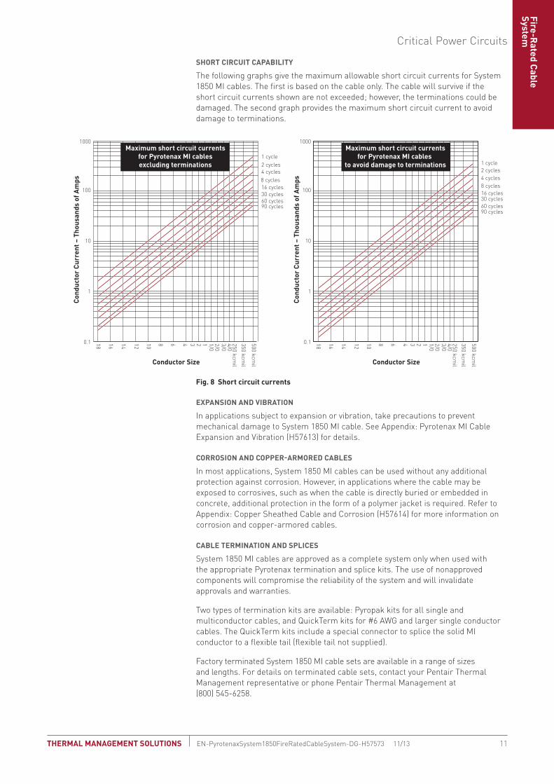
The following graphs give the maximum allowable short circuit currents for System 1850 MI cables. The first is based on the cable only. The cable will survive if the short circuit currents shown are not exceeded; however, the terminations could be damaged. The second graph provides the maximum short circuit current to avoid damage to terminations.
10
100
1000
Conductor Size
18 1416 12 10 8 6 4 3 2 1 1/02/03/04/0250 kcm
il350 kcm
il
500 kcmil
Cond
ucto
r Cu
rren
t – T
hous
ands
of A
mps
0.1
1
0.1
1
10
100
1000
Conductor Size
1 cycle2 cycles4 cycles8 cycles16 cycles30 cycles60 cycles90 cycles
18 1416 12 10 8 6 4 3 2 1 1/02/03/04/0250 kcm
il350 kcm
il
500 kcmil
Cond
ucto
r Cu
rren
t – T
hous
ands
of A
mps
1 cycle2 cycles4 cycles8 cycles16 cycles30 cycles60 cycles90 cycles
Maximum short circuit currentsfor Pyrotenax MI cablesexcluding terminations
Maximum short circuit currentsfor Pyrotenax MI cables
to avoid damage to terminations
Fig. 8 short circuit currents
exPAnsIon And VIbRAtIon
In applications subject to expansion or vibration, take precautions to prevent mechanical damage to System 1850 MI cable. See Appendix: Pyrotenax MI Cable Expansion and Vibration (H57613) for details.
CoRRosIon And CoPPeR-ARMoRed CAbLes
In most applications, System 1850 MI cables can be used without any additional protection against corrosion. However, in applications where the cable may be exposed to corrosives, such as when the cable is directly buried or embedded in concrete, additional protection in the form of a polymer jacket is required. Refer to Appendix: Copper Sheathed Cable and Corrosion (H57614) for more information on corrosion and copper-armored cables.
CAbLe teRMInAtIon And sPLICes
System 1850 MI cables are approved as a complete system only when used with the appropriate Pyrotenax termination and splice kits. The use of nonapproved components will compromise the reliability of the system and will invalidate approvals and warranties.
Two types of termination kits are available: Pyropak kits for all single and multiconductor cables, and QuickTerm kits for #6 AWG and larger single conductor cables. The QuickTerm kits include a special connector to splice the solid MI conductor to a flexible tail (flexible tail not supplied).
Factory terminated System 1850 MI cable sets are available in a range of sizes and lengths. For details on terminated cable sets, contact your Pentair Thermal Management representative or phone Pentair Thermal Management at (800) 545-6258.
Critical Power Circuits
11 THERMAL MANAGEMENT SOLUTIONS EN-PyrotenaxSystem1850FireRatedCableSystem-DG-H57573 11/13

Pyropak termination kit QuickTerm termination kit
Spacer disk andinsulating sleevingassembly
Brasspot
Mastic sealingcompound
Brass gland connector
QuickTerm
Cable Ref.
Caution
Heat-shrinkable tubing Identification card
Brass gland connector
Copper crimpconnector
Self-amalgamating tape
Emery paper
Fig. 9 terminations for system 1850 MI cable
In cases where the manufactured length is shorter than the required run length, a splice is used to join individual lengths of cable. Two options for splicing System 1850 MI cable are available:
Factory fire-rated splice: A UL/ULC 2-hour fire-rated, all-welded joint is installed at the factory.
Field-installed fire-rated splice: A field-installed splice, consisting of a splice kit and a separate field installed fire protection kit, is used to extend cable length or to repair a damaged cable.
Factory splice
Field-installed splice
Fig. 10 splices for system 1850 MI cable
SYSTEM 1850 FIRE-RATED CABLE SYSTEM
THERMAL MANAGEMENT SOLUTIONSEN-PyrotenaxSystem1850FireRatedCableSystem-DG-H57573 11/1312

Fire-Rated Cable
SystemSpace Saving Cable System
Service Entrance Cable System
sCodes and Standards
Technical Data Sheets
Appendixes
tyPICAL systeM InstALLAtIon
A typical critical power circuit installation utilizing System 1850 MI cable is shown in Fig. 11. Additionally, components and accessories available for single and multiconductor MI cables are shown in Table 1. For further information on components and accessories, see the product data sheet in the Technical Data section.
Emergencysplitter
Emergencysplitter
Generator
Firepump
Transferswitch
Transferswitch
Mainelectricalswitchgear
Gearclamp
Factoryjoint
Brass plate
QuickTerm termination kit
Flexibletails
Pipeclamp
System 1850 fire-rated MI cable
Fig. 11 typical system 1850 power circuit system
tAbLe 1 CoMPonent And ACCessoRy AVAILAbILIty
single conductor MI Multiconductor MI
Pyropak termination kit • •
QuickTerm termination kit •
Field and factory splices • •
Brass plates •
Installation Guidelines
These installation guidelines apply to System 1850 MI cables only. When installing a system, refer to the requirements in the UL/ULC Fire Resistance Directory and System 1850 data sheet and installation instructions shipped with the product, and available on the Pentair Thermal Management web site at www.pentairthermal.com. Refer to national and local electrical codes for additional details. For further information, contact your Pentair Thermal Management representative or phone Pentair Thermal Management at (800) 545-6258.
sUPPoRtInG systeM 1850 MI CAbLe
It is important that all support components are made of appropriate materials, such as copper, steel, stainless steel, and concrete. Low melting point or combustible materials such as aluminum, brass, plastic, lead, wood, etc. are not acceptable.
Critical Power Circuits
13 THERMAL MANAGEMENT SOLUTIONS EN-PyrotenaxSystem1850FireRatedCableSystem-DG-H57573 11/13

System 1850 MI cable may be directly mounted on noncombustible surfaces such as concrete or masonry, or supported by steel rod and channel (trapeze) systems. To achieve free air rating, spacing must be maintained between the cable bundles and also between the bundles and the mounting surface; refer to Fig. 12. UL/ULC listing requirements for fire-rated cables stipulate support spacing at certain intervals; refer to the installationinstructions shipped with the product and available on the Pentair Thermal Management web site, www.pentairthermal.com.
System 1850 MI cable should not be installed in conduit, other than when transitioning through a wall, floor, or ceiling.
Steelrod
1-1/2" channel(to maintain NEC/CEC
free air rating)Multiconductor
cable
Free air-ratedinstallation
Free air-rated installation
Surface-mounted installation
Singleconductor
cables Steelchannel
Noncombustiblematerial
Noncombustiblematerial
Singleconductorcables
Fig. 12 supporting system 1850 MI cable
It is important to keep the overall loading on the rod and channel system within limits. Table 2 shows the recommended loading guidelines based on the minimum channel depth of 1-1/2 inch. Note that the cable load calculations as shown in Table 2 take into account only the load represented by the MI cable.
tAbLe 2 LoAdInG GUIdeLInes
Cable load* support method
Up to 150 lbs (68 kg) 3/8" (10 mm) threaded rod
Between 150 lbs and 267 lbs (68 kg and 121 kg) 1/2" (13 mm) threaded rod
Between 267 lbs and 400 lbs (121 kg and 182 kg) 5/8" (16 mm) threaded rod
Channel
1. Maximum width of 1-1/2 in (38 mm) channel: 36 in (915 mm)
2. Maximum load per channel = 200 lbs (91 kg). Channel may be doubled to increase load to 400 lb (182 kg) or reduce spacing between supports ensuring that cable load does not exceed 200 lbs/channel.
* Cable load (lbs) = lbs/ft cable x total number of runs x spacing between supports mea-sured in feet
Cable load (kg) = kg/m cable x total number of runs x spacing between supports mea-sured in meters
note: UL/ULC listing requirements for fire-rated cables stipulate support spacing at cer-tain intervals; refer to the installation instructions shipped with the product and available on the Pentair Thermal Management web site, www.pentairthermal.com.
seIsMIC ConsIdeRAtIons
In areas where there is a risk of seismic activity, precautions must be taken where the cable crosses expansion joints and at termination points. For more information, see Appendix: Pyrotenax MI Cable Expansion and Vibration (H57613).
SYSTEM 1850 FIRE-RATED CABLE SYSTEM
THERMAL MANAGEMENT SOLUTIONSEN-PyrotenaxSystem1850FireRatedCableSystem-DG-H57573 11/1314

Fire-Rated Cable
SystemSpace Saving Cable System
Service Entrance Cable System
sCodes and Standards
Technical Data Sheets
Appendixes
CAbLe LAyoUt
In multiconductor cables, the magnetic effects of the phase conductors cancel each other out, allowing for cable installation in any configuration. However, single conductor cables should be bundled in groups containing one conductor from each phase to minimize the resulting magnetic field in each grouping. The grouped single conductor cables are then fastened tightly together, ensuring that the gland connectors at each end of the cable run are connected to the metal enclosure through a nonferrous entry, such as a brass plate, or in accordance with national electrical codes. Typical single conductor cable configurations are shown in Fig. 13. The neutral conductor may be located within or outside the cable group.
Single circuit(preferred)
Single circuit(alternative)
Two cables inparallel per phase
(preferred)Two cables in
parallel per phase(alternative)
Three or more cablesin parallel per phase
(preferred)Three or more cablesin parallel per phase
(alternative)
Note: For free air ampere ratings, the spacing “S” between bundles should be a minimum of 2.15 cable diameters in the U.S. (NEC) and Canada (CEC). For magnetic effect purposes, the neutral may be located as shown, or outside groups in the most convenient location.
S
S S
S S S
S
S
S
S
S
S
S
S
S
SS S
Single Phase Three-Phase • 3 Wire Three-Phase • 4 Wire
Fig. 13 Recommended installation configurations
Electrical codes generally limit paralleling cable configurations to cable sizes 1/0 AWG and larger. The codes address the balancing of resistance by stipulating:
• All conductors must be the same length
• All conductors must be the same size and the same material
• All conductors must have the same type of insulation
• All conductors must be terminated in the same manner
A current measurement should be taken immediately after the cables begin to carry load. Load imbalances between conductors of up to 10% are tolerable and expected. Deviations above 10% must be investigated and corrected.
When installing single conductor cables through a ferrous enclosure, precautions must be taken to prevent induction heating in the steel. This is accomplished by removing a section of the enclosure and installing a nonferrous brass plate (in Canada, this is only required above 200 amperes). Brass plates with pretapped holes are available for the gland connectors.
Critical Power Circuits
15 THERMAL MANAGEMENT SOLUTIONS EN-PyrotenaxSystem1850FireRatedCableSystem-DG-H57573 11/13
Brassplate
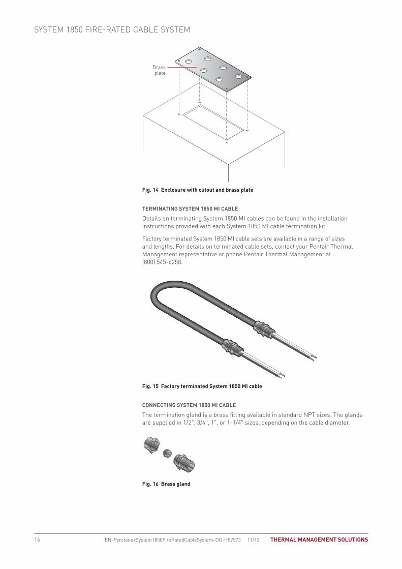
Fig. 14 enclosure with cutout and brass plate
teRMInAtInG systeM 1850 MI CAbLe
Details on terminating System 1850 MI cables can be found in the installation instructions provided with each System 1850 MI cable termination kit.
Factory terminated System 1850 MI cable sets are available in a range of sizes and lengths. For details on terminated cable sets, contact your Pentair Thermal Management representative or phone Pentair Thermal Management at (800) 545-6258.
Fig. 15 Factory terminated system 1850 MI cable
ConneCtInG systeM 1850 MI CAbLe
The termination gland is a brass fitting available in standard NPT sizes. The glands are supplied in 1/2", 3/4", 1", or 1-1/4" sizes, depending on the cable diameter.
Fig. 16 brass gland
SYSTEM 1850 FIRE-RATED CABLE SYSTEM
THERMAL MANAGEMENT SOLUTIONSEN-PyrotenaxSystem1850FireRatedCableSystem-DG-H57573 11/1316

Fire-Rated Cable
SystemSpace Saving Cable System
Service Entrance Cable System
sCodes and Standards
Technical Data Sheets
Appendixes
Gland size information for each MI cable is available from the product data sheets in the Technical Data section. When tightened with the recommended torque, 25 ft-lbs for all gland sizes, this gland simultaneously seals the enclosure and grips the cable through a brass compression sleeve. This connection, when installed according to the installation instructions, provides the following benefits:
• Code-compliant bonding path from the cable sheath.
• Hydrostatic withstand pressure up to 500 lbs/in2 (35 kg/cm2)
note: Terminations are not required to be fire-rated since the emergency equipment they serve is in a fire-rated room.
Critical Power Circuits
17 THERMAL MANAGEMENT SOLUTIONS EN-PyrotenaxSystem1850FireRatedCableSystem-DG-H57573 11/13

SYSTEM 1850 FIRE-RATED CABLE SYSTEM
THERMAL MANAGEMENT SOLUTIONSEN-PyrotenaxSystem1850FireRatedCableSystem-DG-H57573 11/1318

Fire-Rated Cables
Space Saving Cable System
Service Entrance Cable System
sCodes and Standards
Technical Data Sheets
Appendixes
This section provides an overview of general circuit design considerations and installation guidelines for Pyrotenax System 1850 Power Cables in space savings applications. For additional information, contact your Pentair Thermal Management representative or phone Pentair Thermal Management at (800) 545-6258. Also, visit our web site at www.pentairthermal.com.
ContentsIntroduction . . . . . . . . . . . . . . . . . . . . . . . . . . . . . . . . . . . . . . . . . . . . . . . . . . . . . . . . . . 20
Typical Locations . . . . . . . . . . . . . . . . . . . . . . . . . . . . . . . . . . . . . . . . . . . . . . . . . 20System 1850 Mineral Insulated Cable . . . . . . . . . . . . . . . . . . . . . . . . . . . . . . . . 20
Construction. . . . . . . . . . . . . . . . . . . . . . . . . . . . . . . . . . . . . . . . . . . . . . . . . . . 20Configurations . . . . . . . . . . . . . . . . . . . . . . . . . . . . . . . . . . . . . . . . . . . . . . . . . 20
Approvals and Certifications . . . . . . . . . . . . . . . . . . . . . . . . . . . . . . . . . . . . . . . . 21Circuit Design Considerations . . . . . . . . . . . . . . . . . . . . . . . . . . . . . . . . . . . . . . . . . . . 21
Cable Sizing . . . . . . . . . . . . . . . . . . . . . . . . . . . . . . . . . . . . . . . . . . . . . . . . . . . . . . 21Voltage Drop . . . . . . . . . . . . . . . . . . . . . . . . . . . . . . . . . . . . . . . . . . . . . . . . . . . . . 22Equipment Bonding . . . . . . . . . . . . . . . . . . . . . . . . . . . . . . . . . . . . . . . . . . . . . . . 22Short Circuit Capability. . . . . . . . . . . . . . . . . . . . . . . . . . . . . . . . . . . . . . . . . . . . . 23Expansion and Vibration . . . . . . . . . . . . . . . . . . . . . . . . . . . . . . . . . . . . . . . . . . . . 23Corrosion and Copper-armored Cables . . . . . . . . . . . . . . . . . . . . . . . . . . . . . . . 23Cable Termination . . . . . . . . . . . . . . . . . . . . . . . . . . . . . . . . . . . . . . . . . . . . . . . . . 24Cable Splices . . . . . . . . . . . . . . . . . . . . . . . . . . . . . . . . . . . . . . . . . . . . . . . . . . . . . 25Typical Space Saving System Installation . . . . . . . . . . . . . . . . . . . . . . . . . . . . . 26
Installation Guidelines . . . . . . . . . . . . . . . . . . . . . . . . . . . . . . . . . . . . . . . . . . . . . . . . . 27Supporting Space Saving MI Cables . . . . . . . . . . . . . . . . . . . . . . . . . . . . . . . . . . 27Seismic Considerations . . . . . . . . . . . . . . . . . . . . . . . . . . . . . . . . . . . . . . . . . . . . 27Cable Layout . . . . . . . . . . . . . . . . . . . . . . . . . . . . . . . . . . . . . . . . . . . . . . . . . . . . . 27Terminating System 1850 MI Cables . . . . . . . . . . . . . . . . . . . . . . . . . . . . . . . . . . 29Connecting System 1850 MI Cable . . . . . . . . . . . . . . . . . . . . . . . . . . . . . . . . . . . 29
19 THERMAL MANAGEMENT SOLUTIONS EN-PyrotenaxSpaceSavingCableSystem-DG-H57574 11/13
SPACE SAVING CABLE SYSTEM

IntRodUCtIon
Increased power consumption due to the expansion of office space in existing buildings, as well as the conversion of buildings to commercial use, has resulted in greater demand for the retrofitting of electrical power feeders. In many instances, this involves installing power cable in constricted spaces and along difficult runs.
Pentair Thermal Management Pyrotenax System 1850 mineral insulated (MI) power cable allows up to 80% space savings over traditional rigid conduit and wire solutions, and are easily installed in areas where space is limited.
typical Locations
System 1850 MI power cables, when used in space saving applications, are ideal for high capacity feeders and low profile wiring in the following locations:
• Older high-rise buildings
• Historic buildings
• Health care facilities
• Any location where space is limited
system 1850 Mineral Insulated Cable
System 1850 MI cable offers a unique combination of dependability, versatility, and permanence while capable of operating continuously at ambient temperatures as high as 250°C (482°F).
ConstRUCtIon
Pyrotenax System 1850 MI cables are manufactured using only inorganic materials, copper and magnesium oxide. This construction is inherently tough, yet allows the cable to be bent and molded to fit into tight spaces. In addition, the totally inorganic construction of unjacketed System 1850 MI cable allows for an environmentally clean electrical cable that does not burn, produce smoke, or add fuel when exposed to fire conditions.
Fig. 1 system 1850 MI cable construction
System 1850 MI cables have a seamless metal sheath that allows the cable to withstand bending, twisting, pulling, and mechanical abrasion, while remaining fully functional. For superior corrosion protection, an optional polymer jacket is available and is suitable for use in temperatures as low as –40°C (–40°F).
ConFIGURAtIons
System 1850 MI cables are available in a range of sizes and conductor configurations, allowing for use in a diverse range of applications. For specifications, see the product data sheet in the Technical Data section.
Solid copper conductors
Magnesium oxide (MgO) insulation
Seamless copper sheath
SPACE SAVING CABLE SYSTEM
THERMAL MANAGEMENT SOLUTIONSEN-PyrotenaxSpaceSavingCableSystem-DG-H57574 11/1320

Fire-Rated Cables
Space Saving Cable System
Service Entrance Cable System
sCodes and Standards
Technical Data Sheets
Appendixes
Approvals and Certifications
Pyrotenax System 1850 MI cables meet the applicable requirements of the U.S. National Electrical Code (NEC) and the Canadian Electrical Code (CEC), and are UL Listed and CSA Certified in North America.
Factory terminated MI cable sets are approved for nonhazardous locations and hazardous locations. For specific approval information, see the product data sheet in the Technical Data section.
Pyrotenax power cables are also available for use outside North America and are manufactured to BS EN 60702-1 & 60702-2, Mineral Insulated Cables and Terminations. Contact Pentair Thermal Management for information on our range of cables certified for use worldwide.
CIRCUIt desIGn ConsIdeRAtIons
Power cable systems should only be designed by professionals familiar with generally accepted design practices. The information provided below relates specifically to designs using Pyrotenax MI power cables and must be followed, along with all relevant local codes and standards, to ensure that the systems are designed properly. For additional information, contact your Pentair Thermal Management representative or phone Pentair Thermal Management at (800) 545-6258.
Cable sizing
Power cable size is based on circuit breaker size, which in turn is based on load calculations. Special rules apply for motors where cable size is based on 125% of full load current. Use the ampacity tables specified in the electrical code to determine the cable size. If the calculated voltage drop exceeds the specified limits, a larger cable size must be chosen.
The NEC and CEC allow full “free air” ampacity for unjacketed single conductor Pyrotenax MI cables configured according to Fig. 2 as long as a space of 2.15 cable diameters is maintained between bundles.
Fig. 2 spacing of bundled conductors
Under the installation conditions shown in Fig. 2, the termination may need to be “sized-up” to keep it within its temperature limits in accordance with electrical code requirements (NEC 110.14(C)). MI cable terminations should be sized up in accordance with the installation instructions supplied with the termination kit.
(S)
(S)
MulticonductorMI cable
Single conductorMI or MC
cables
Spacing (S) between multiphase paralleled single conductor cables
Note: For free air ampere ratings, the spacing “S” between bundles should be a minimum of 2.15 cable diameters in the U.S. (NEC) and Canada (CEC).
Circuit Design Considerations
21 THERMAL MANAGEMENT SOLUTIONS EN-PyrotenaxSpaceSavingCableSystem-DG-H57574 11/13

Voltage drop
Voltage drop calculations are based on calculated load, not circuit breaker rating.
For conventional cables, simple formulas are used to determine if the cable size listed in the ampacity tables meets the required voltage drop limits. While these formulas can be applied to System 1850 MI cable, voltage drop values specific to the characteristics of MI cable can be calculated using any of the following:
• A quick voltage drop calculator is available on the Pentair Thermal Management web site, www.pentairthermal.com
• PyroSizer MI cable sizing software is available on the Pentair Thermal Manage-ment web site, www.pentairthermal.com, or through your Pentair Thermal Man-agement representative
equipment bonding
The copper sheath of System 1850 MI cables meets North American code requirements for an equipment grounding conductor, The brass gland completes the grounding path from the cable sheath to the equipment. For single conductor cables, the ground path includes a nonferrous brass plate as shown in Fig. 3 (in Canada, brass plates are required only for ampacities over 200 A).
Fig. 3 equipment bonding using brass plate
MulticonductorMI cable
Brass glandBrass plate
Enclosure wall
Lock washer
Details of brass plate
Steel enclosure cutout(steel must be removed)
Lock washer
Single conductorMI cable
Locknuts
SPACE SAVING CABLE SYSTEM
THERMAL MANAGEMENT SOLUTIONSEN-PyrotenaxSpaceSavingCableSystem-DG-H57574 11/1322

Fire-Rated Cables
Space Saving Cable System
Service Entrance Cable System
sCodes and Standards
Technical Data Sheets
Appendixes
short Circuit Capability
The following graphs give the maximum allowable short circuit currents for System 1850 MI cables. The first is based on the cable only. The cable will survive if the short circuit currents shown are not exceeded; however, the terminations could be damaged. The second graph provides the maximum short circuit current to avoid damaging the terminations.
Fig. 4 short circuit currents for system 1850 MI cable
expansion and Vibration
In applications subject to expansion or vibration, take precautions to prevent mechanical damage to System 1850 MI cables. Refer to appendix: Pyrotenax MI Cable Expansion and Vibration (H57613) for details.
Corrosion and Copper-armored Cables
In most applications, System 1850 MI cables can be used without any additional protection against corrosion. However, in applications where the cable may be exposed to corrosives, such as when the cable is directly buried or embedded in concrete, additional protection in the form of a polymer jacket is recommended. Refer to appendix: Copper Sheathed Cable and Corrosion (H57614) for details.
10
100
1000
Conductor Size
18 1416 12 10 8 6 4 3 2 1 1/02/03/04/0250 kcm
il350 kcm
il
500 kcmil
Cond
ucto
r Cu
rren
t – T
hous
ands
of A
mps
0.1
1
0.1
1
10
100
1000
Conductor Size
1 cycle2 cycles4 cycles8 cycles16 cycles30 cycles60 cycles90 cycles
18 1416 12 10 8 6 4 3 2 1 1/02/03/04/0250 kcm
il350 kcm
il
500 kcmil
Cond
ucto
r Cu
rren
t – T
hous
ands
of A
mps
1 cycle2 cycles4 cycles8 cycles16 cycles30 cycles60 cycles90 cycles
Maximum short circuit currents for Pyrotenax MI cablesexcluding terminations
Maximum short circuit currentsfor Pyrotenax MI cables
to avoid damage to terminations
Circuit Design Considerations
23 THERMAL MANAGEMENT SOLUTIONS EN-PyrotenaxSpaceSavingCableSystem-DG-H57574 11/13
Cable termination
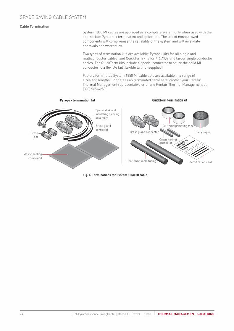
System 1850 MI cables are approved as a complete system only when used with the appropriate Pyrotenax termination and splice kits. The use of nonapproved components will compromise the reliability of the system and will invalidate approvals and warranties.
Two types of termination kits are available: Pyropak kits for all single and multiconductor cables, and QuickTerm kits for # 6 AWG and larger single conductor cables. The QuickTerm kits include a special connector to splice the solid MI conductor to a flexible tail (flexible tail not supplied).
Factory terminated System 1850 MI cable sets are available in a range of sizes and lengths. For details on terminated cable sets, contact your Pentair Thermal Management representative or phone Pentair Thermal Management at (800) 545-6258.
Fig. 5 terminations for system 1850 MI cable
Pyropak termination kit QuickTerm termination kit
Spacer disk andinsulating sleevingassembly
Brasspot
Mastic sealingcompound
Brass gland connector
QuickTerm
Cable Ref.
Caution
Heat-shrinkable tubing Identification card
Brass gland connector
Copper crimpconnector
Self-amalgamating tape
Emery paper
SPACE SAVING CABLE SYSTEM
THERMAL MANAGEMENT SOLUTIONSEN-PyrotenaxSpaceSavingCableSystem-DG-H57574 11/1324
Fire-Rated Cables
Space Saving Cable System
Service Entrance Cable System
sCodes and Standards
Technical Data Sheets
Appendixes
Cable splices
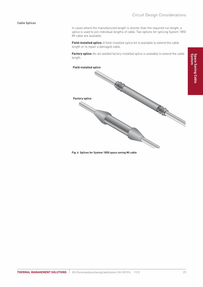
In cases where the manufactured length is shorter than the required run length, a splice is used to join individual lengths of cable. Two options for splicing System 1850 MI cable are available:
Field-installed splice: A field-installed splice kit is available to extend the cable length or to repair a damaged cable.
Factory splice: An all-welded factory installed splice is available to extend the cable length.
Fig. 6 splices for system 1850 space saving MI cable
Factory splice
Field-installed splice
Circuit Design Considerations
25 THERMAL MANAGEMENT SOLUTIONS EN-PyrotenaxSpaceSavingCableSystem-DG-H57574 11/13

typical space saving system Installation
A typical space saving power circuit installation utilizing System 1850 MI cable is shown in Figure 7. Additionally, components and accessories available for single and multiconductor MI cables are shown in Table 1. For further information on components and accessories, see the product data sheet in the Technical Data section.
Fig. 7 typical single conductor system 1850 space saving power cable system
tAbLe 1 CoMPonent And ACCessoRy AVAILAbILIty FoR systeM 1850 MI PoweR CAbLe
single conductor MI Multiconductor MI
Pyropak termination kit • •
QuickTerm termination kit •
Field and factory splices • •
Brass plates •
Main electricalswitchgear
Field splices
Equipmentenclosure
Brassplate
Gearclamp
Pipeclamp
Power cable
SPACE SAVING CABLE SYSTEM
THERMAL MANAGEMENT SOLUTIONSEN-PyrotenaxSpaceSavingCableSystem-DG-H57574 11/1326

Fire-Rated Cables
Space Saving Cable System
Service Entrance Cable System
sCodes and Standards
Technical Data Sheets
Appendixes
InstALLAtIon GUIdeLInes
These installation guidelines apply to System 1850 MI cables used in space saving applications. For further details, refer to national and local electrical codes, the System 1850 data sheet, and the installation instructions shipped with the product. The data sheet and installation instructions are available on the Pentair Thermal Management web site at www.pentairthermal.com. Contact your Pentair Thermal Management representative or phone Pentair Thermal Management at (800) 545-6258 for additional information.
supporting space saving MI Cables
System 1850 MI cables used in space savings applications may be directly mounted on any surface or supported by rod and channel (trapeze) systems. To achieve free air rating, spacing must be maintained between the cable bundles and also between the bundles and the mounting surface; refer to Fig. 8. Pentair Thermal Management and electrical codes require support spacing at certain intervals; refer to the installation instructions shipped with the product and available on the Pentair Thermal Management web site, www.pentairthermal.com.
Other than transitions through a wall, floor, or ceiling, MI cable should not be installed in conduit.
Supportingrod
1-1/2" channel(to maintain NEC/CEC
free air rating)Multiconductor
cable
Free air-ratedinstallation
Free air-ratedinstallation
Surface mountedinstallation
Singleconductor
cables Steelchannel
Mountingsurface
Mountingsurface
Singleconductorcables
Fig. 8 system 1850 MI cables in space savings applications
seismic Considerations
In areas where there is a risk of seismic activity, precautions must be taken where the cable crosses expansion joints and at termination points. Refer to appendix: Pyrotenax MI Cable Expansion and Vibration (H57613) for details.
Cable Layout
In multiconductor cables, the magnetic effects of the phase conductors cancel each other out, allowing for cable installation in any configuration. However, single conductor cables should be bundled in groups containing one conductor from each phase to minimize the resulting magnetic field in each grouping. The grouped single conductor cables are then fastened tightly together, ensuring that the gland connectors at each end of the cable run are connected to the metal enclosure through a nonferrous entry, such as a brass plate, or in accordance with national electrical codes. Typical single conductor cable configurations are shown in Fig. 9. The neutral conductor may be located within or outside the cable group.
Installation Guidelines
27 THERMAL MANAGEMENT SOLUTIONS EN-PyrotenaxSpaceSavingCableSystem-DG-H57574 11/13

Single Phase Three-Phase • 3 Wire Three-Phase • 4 Wire
Single circuit(preferred)
Single circuit(alternative)
Two cables inparallel per phase
(preferred)Two cables in
parallel per phase(alternative)
Three or more cablesin parallel per phase
(preferred)Three or more cablesin parallel per phase
(alternative)
Note: For free air ampere ratings, the spacing “S” between bundles should be a minimum of 2.15 cable diameters in the U.S. (NEC) and Canada (CEC). For magnetic effect purposes, the neutral may be located as shown, or outside groups in the most convenient location.
S
S S
S S S
S
S
S
S
S
S
S
S
S
SS S
Fig. 9 Recommended installation configurations
Electrical codes generally limit paralleling cable configurations to cable sizes 1/0 AWG and larger. The codes address the balancing of resistance by stipulating:
• All conductors must be the same length
• All conductors must be the same size and the same material
• All conductors must have the same type of insulation
• All conductors must be terminated in the same manner
A current measurement should be taken immediately after the cables begin to carry load. Load imbalances between conductors of up to 10% are tolerable and expected. Deviations above 10% must be investigated and corrected.
When installing single conductor cables through a ferrous enclosure, precautions must be taken to prevent induction heating in the steel. This is accomplished by removing a section of the enclosure and installing a nonferrous brass plate (in Canada, this is only required above 200 A). Brass plates with pretapped holes are available for the gland connectors.
Fig. 10 enclosure with cutout and brass plate
Brassplate
SPACE SAVING CABLE SYSTEM
THERMAL MANAGEMENT SOLUTIONSEN-PyrotenaxSpaceSavingCableSystem-DG-H57574 11/1328

Fire-Rated Cables
Space Saving Cable System
Service Entrance Cable System
sCodes and Standards
Technical Data Sheets
Appendixes
terminating system 1850 MI Cables
Details on terminating System 1850 MI cables can be found in the installation instructions provided with each System 1850 MI cable termination kit.
Factory terminated System 1850 MI cable sets are available in a range of sizes and lengths. For details on terminated cable sets, contact your Pentair Thermal Management representative or phone Pentair Thermal Management at (800) 545-6258.
Fig. 11 Factory terminated system 1850 MI cable
Connecting system 1850 MI Cable
The termination gland is a brass fitting available in standard NPT sizes. The glands are supplied in 1/2", 3/4", 1", or 1-1/4" sizes, depending on the cable diameter.
Fig. 12 brass gland
Gland size information for each MI cable is available from the product data sheets in the Technical Data section. When tightened with the recommended torque (25 ft-lbs), this gland simultaneously seals the enclosure and grips the cable through a brass compression sleeve. This connection, when installed according to the installation instructions, provides the following benefits:
• Code-compliant bonding path through the cable sheath
• Hydrostatic withstand pressure up to 500 lbs/in2 (35 kg/cm2)
Installation Guidelines
29 THERMAL MANAGEMENT SOLUTIONS EN-PyrotenaxSpaceSavingCableSystem-DG-H57574 11/13

SPACE SAVING CABLE SYSTEM
THERMAL MANAGEMENT SOLUTIONSEN-PyrotenaxSpaceSavingCableSystem-DG-H57574 11/1330

Fire-Rated Cables
Space Saving Cable System
Service Entrance Cable System
Codes and StandardsTechnical D
ata SheetsAppendixes
This section provides an overview of general circuit design considerations and installation guidelines for a Pyrotenax System 1850-SE Service Entrance (SE) mineral insulated cable system. This system is designed as an alternative to concrete encasement for service conductors. Where conditions make concrete encasement difficult or impractical, Authorities Having Jurisdiction (AHJs) have accepted this system as an alternative to concrete encasement. For additional information, contact your Pentair Thermal Management representative or phone Pentair Thermal Management at (800) 545-6258. Also, visit our web site at www.pentairthermal.com.
Contents
Introduction . . . . . . . . . . . . . . . . . . . . . . . . . . . . . . . . . . . . . . . . . . . . . . . . . . . . . . . . . . 31Typical Locations . . . . . . . . . . . . . . . . . . . . . . . . . . . . . . . . . . . . . . . . . . . . . . . . . 32System 1850-SE . . . . . . . . . . . . . . . . . . . . . . . . . . . . . . . . . . . . . . . . . . . . . . . . . . 32
Ventilated Tray . . . . . . . . . . . . . . . . . . . . . . . . . . . . . . . . . . . . . . . . . . . . . . . . . 33Approvals and Certifications . . . . . . . . . . . . . . . . . . . . . . . . . . . . . . . . . . . . . . . . 33
Circuit Design Considerations . . . . . . . . . . . . . . . . . . . . . . . . . . . . . . . . . . . . . . . . . . . 33Cable Sizing . . . . . . . . . . . . . . . . . . . . . . . . . . . . . . . . . . . . . . . . . . . . . . . . . . . . . . 33Voltage Drop . . . . . . . . . . . . . . . . . . . . . . . . . . . . . . . . . . . . . . . . . . . . . . . . . . . . . 34Equipment Bonding . . . . . . . . . . . . . . . . . . . . . . . . . . . . . . . . . . . . . . . . . . . . . . . 34Short Circuit Capability. . . . . . . . . . . . . . . . . . . . . . . . . . . . . . . . . . . . . . . . . . . . . 35Expansion and Vibration . . . . . . . . . . . . . . . . . . . . . . . . . . . . . . . . . . . . . . . . . . . . 35Corrosion and MI Cable . . . . . . . . . . . . . . . . . . . . . . . . . . . . . . . . . . . . . . . . . . . . 35Lightning Protection . . . . . . . . . . . . . . . . . . . . . . . . . . . . . . . . . . . . . . . . . . . . . . . 35Cable Termination . . . . . . . . . . . . . . . . . . . . . . . . . . . . . . . . . . . . . . . . . . . . . . . . . 36Factory and Field Splices . . . . . . . . . . . . . . . . . . . . . . . . . . . . . . . . . . . . . . . . . . . 36Typical System Installation. . . . . . . . . . . . . . . . . . . . . . . . . . . . . . . . . . . . . . . . . . 37
Installation Guidelines . . . . . . . . . . . . . . . . . . . . . . . . . . . . . . . . . . . . . . . . . . . . . . . . . 37Supporting System 1850-SE . . . . . . . . . . . . . . . . . . . . . . . . . . . . . . . . . . . . . . . . 38Seismic Considerations . . . . . . . . . . . . . . . . . . . . . . . . . . . . . . . . . . . . . . . . . . . . 39Cable Layout . . . . . . . . . . . . . . . . . . . . . . . . . . . . . . . . . . . . . . . . . . . . . . . . . . . . . 39Terminating System 1850-SE MI Cable . . . . . . . . . . . . . . . . . . . . . . . . . . . . . . . . 40Connecting System 1850-SE MI Cable . . . . . . . . . . . . . . . . . . . . . . . . . . . . . . . . 40
IntRodUCtIon
Increased power consumption due to the expansion of office space in existing buildings, as well as the conversion of buildings to commercial use, has resulted in greater demand for electrical power. Retrofitting service conductors can present particular difficulties as the electrical room is often located at a distance from the service entrance point. While this was a good location when the building was first constructed and service cables could easily be encased in concrete in the floor, it gives rise to significant difficulties after the fact, when encasement of the additional service conductors can be virtually impossible because of constricted space and congestion in service areas.
Pentair Thermal Management Pyrotenax System 1850-SE allows up to 80% space savings over traditional rigid conduit and wire solutions. The decision to accept the system as a alternative to concrete encasement is the responsibility of the Authorities Having Jurisdiction (AHJs). If accepted, either on a case-by-case basis or carte blanche as has been the case in several major cities, the system provides an effective solution to a difficult problem.
31 THERMAL MANAGEMENT SOLUTIONS EN-PyrotenaxSystem1850ServiceEntranceCable-DG-H57575 11/13
SYSTEM 1850-SE SERVICE ENTRANCE CABLE SYSTEM

typical Locations
System 1850-SE is ideal for high-capacity feeders and low-profile wiring in the following locations:
• Older high-rise buildings
• Historic buildings
• Health care facilities
system 1850-se
A Pyrotenax System 1850-SE installation consists of System 1850 2-hour fire-rated single conductor MI cable, with special terminations for service entrance applications, and enclosed ventilated cable tray. System 1850-SE should be supported by steel rod and channel (trapeze) systems in one of two configurations.
DANGER
LIVE 600 V ELECTRICAL SERVICE
HIGH VOLTAGE STAY CLEAR
Steelrod
Steelchannel
Tray
Singleconductor
cables
DANGER
LIVE 600 V ELECTRICAL SERVICE
HIGH VOLTAGE STAY CLEAR
Singleconductor
cables
Steelrod
Steelchannel
Tray
Fig. 1 system 1850-se configurations
System 1850-SE MI cable is installed in an enclosed ventilated tray labeled along its length with warnings that this is a “live electrical service.”
systeM 1850 2-HoUR FIRe-RAted MIneRAL InsULAted CAbLe
Pyrotenax System 1850 MI wiring cables are manufactured using only inorganic materials, copper and magnesium oxide. This construction is inherently tough, yet allows the cable to be bent and molded to fit into tight spaces. In addition, the totally inorganic construction of unjacketed System 1850 cables allows for an environmentally clean electrical cable that does not burn, produce smoke, or add fuel when exposed to fire conditions.
Solid copper conductor
Magnesium oxide (MgO) insulation
Seamless copper sheath
Fig. 2 system 1850 MI cable construction
For service entrance applications, both 350 kcmil and 500 kcmil single conductor cables are available. For specifications, see the product data sheet in the Technical Data section.
SYSTEM 1850-SE SERVICE ENTRANCE CABLE SYSTEM
THERMAL MANAGEMENT SOLUTIONSEN-PyrotenaxSystem1850ServiceEntranceCable-DG-H57575 11/1332

Fire-Rated Cables
Space Saving Cable System
Service Entrance Cable System
Codes and StandardsTechnical D
ata SheetsAppendixes
VentILAted tRAy
A NEMA Class 12B Stainless steel ventilated tray complete with louvered cover, clamps, 90° and 45° bends, offsets, etc. is supplied.
The steel rod and channel used for the trapeze supports is not supplied.
Approvals and Certifications
All components of System 1850-SE are UL Listed and/or CSA Certified in North America.
CIRCUIt desIGn ConsIdeRAtIons
Service entrance systems should only be designed by professionals familiar with generally accepted design practices. The information provided below relates specifically to designs using Pyrotenax System 1850-SE and must be followed, along with all relevant local codes and standards, to ensure that the systems are designed properly. For additional information, contact your Pentair Thermal Management representative or phone Pentair Thermal Management at (800) 545-6258.
Cable sizing
System 1850-SE MI cable size is based on circuit breaker size, which in turn is based on load calculations. After choosing the appropriate circuit breaker size, use the ampacity tables specified in the electrical code to determine the cable size. If the calculated voltage drop exceeds the specified limits, a larger cable size must be chosen.
The National Electrical Code (NEC) allows full “free air” ampacity for unjacketed single conductor MI cables configured according to Fig. 3 as long as a space of 2.15 cable diameters is maintained between bundles.
Spacing (S) between multiphase paralleled single conductor cables
Tray
(S)
Fig. 3 spacing of bundled conductors
Although unjacketed single conductor MI cable is unaffected by any temperature increase resulting under the installation conditions shown in Fig. 3, the termination may need to be “sized-up” to keep it within its temperature limits in accordance with electrical code requirements. Refer to Table 1, later in this section for more details.
Circuit Design Considerations
33 THERMAL MANAGEMENT SOLUTIONS EN-PyrotenaxSystem1850ServiceEntranceCable-DG-H57575 11/13

Voltage drop
Voltage drop calculations are based on calculated load, not circuit breaker rating.
For conventional cables, simple formulas are used to determine if the cable size listed in the ampacity tables meets the required voltage drop limits. While these formulas can be applied to System 1850-SE MI cable, voltage drop values specific to the characteristics of MI cable can be calculated using any of the following:
• An equation based on the run length, the conductor current, and the circuit volt-age is provided in Appendix: Pyrotenax MI Voltage Drop Calculation (H57611)
• A quick voltage drop calculator is available on the Pentair Thermal Management web site, www.pentairthermal.com
• PyroSizer MI cable sizing software is available from the Pentair Thermal Manage-ment web site, www.pentairthermal.com, or through your Pentair Thermal Man-agement representative
equipment bonding
The copper sheath of System 1850 cables meets the North American code requirements for an equipment grounding conductor. The brass gland completes the grounding path from the cable sheath to the equipment. For single conductor cables, the ground path includes a nonferrous brass plate, as shown in Fig. 4.
Details of brass plate
Single conductorMI cables
Brass plate
Enclosure wall
Brass gland
Lock washer Lock washer
Steel enclosure cutout(steel must be removed)
Fig. 4 equipment bonding using brass plate
SYSTEM 1850-SE SERVICE ENTRANCE CABLE SYSTEM
THERMAL MANAGEMENT SOLUTIONSEN-PyrotenaxSystem1850ServiceEntranceCable-DG-H57575 11/1334
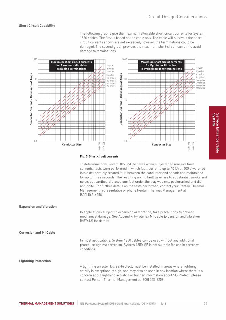
Fire-Rated Cables
Space Saving Cable System
Service Entrance Cable System
Codes and StandardsTechnical D
ata SheetsAppendixes
short Circuit Capability
The following graphs give the maximum allowable short circuit currents for System 1850 cables. The first is based on the cable only. The cable will survive if the short circuit currents shown are not exceeded; however, the terminations could be damaged. The second graph provides the maximum short circuit current to avoid damage to terminations.
10
100
1000
Conductor Size
350 kcmil
500 kcmil
Cond
ucto
r Cu
rren
t – T
hous
ands
of A
mps
0.1
1
0.1
1
10
100
1000
Conductor Size
1 cycle2 cycles4 cycles8 cycles16 cycles30 cycles60 cycles90 cycles
350 kcmil
500 kcmil
Cond
ucto
r Cu
rren
t – T
hous
ands
of A
mps
Maximum short circuit currentsfor Pyrotenax MI cables
to avoid damage to terminations1 cycle2 cycles4 cycles8 cycles16 cycles30 cycles60 cycles90 cycles
Maximum short circuit currentsfor Pyrotenax MI cablesexcluding terminations
Fig. 5 short circuit currents
To determine how System 1850-SE behaves when subjected to massive fault currents, tests were performed in which fault currents up to 40 kA at 600 V were fed into a deliberately created fault between the conductor and sheath and maintained for up to three seconds. The resulting arcing fault gave rise to substantial smoke and noise, but cardboard placed one foot under the tray was only pockmarked and did not ignite. For further details on the tests performed, contact your Pentair Thermal Management representative or phone Pentair Thermal Management at (800) 545-6258.
expansion and Vibration
In applications subject to expansion or vibration, take precautions to prevent mechanical damage. See Appendix: Pyrotenax MI Cable Expansion and Vibration (H57613) for details.
Corrosion and MI Cable
In most applications, System 1850 cables can be used without any additional protection against corrosion. System 1850-SE is not suitable for use in corrosive conditions.
Lightning Protection
A lightning arrester kit, SE-Protect, must be installed in areas where lightning activity is exceptionally high, and may also be used in any location where there is a concern about lightning activity. For further information about SE-Protect, please contact Pentair Thermal Management at (800) 545-6258.
Circuit Design Considerations
35 THERMAL MANAGEMENT SOLUTIONS EN-PyrotenaxSystem1850ServiceEntranceCable-DG-H57575 11/13
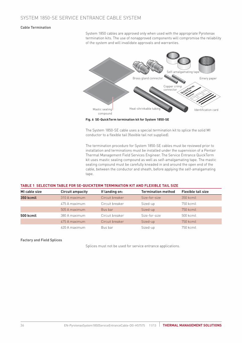
Cable termination
System 1850 cables are approved only when used with the appropriate Pyrotenax termination kits. The use of nonapproved components will compromise the reliability of the system and will invalidate approvals and warranties.
Fig. 6 se-quickterm termination kit for system 1850-se
The System 1850-SE cable uses a special termination kit to splice the solid MI conductor to a flexible tail (flexible tail not supplied).
The termination procedure for System 1850-SE cables must be reviewed prior to installation and terminations must be installed under the supervision of a Pentair Thermal Management Field Services Engineer. The Service Entrance QuickTerm kit uses mastic sealing compound as well as self-amalgamating tape. The mastic sealing compound must be carefully kneaded in and around the open end of the cable, between the conductor and sheath, before applying the self-amalgamating tape.
tAbLe 1 seLeCtIon tAbLe FoR se-qUICkteRM teRMInAtIon kIt And FLexIbLe tAIL sIze
MI cable size Circuit ampacity If landing on: termination method Flexible tail size
350 kcmil 310 A maximum Circuit breaker Size-for-size 350 kcmil
475 A maximum Circuit breaker Sized-up 750 kcmil
505 A maximum Bus bar Sized-up 750 kcmil
500 kcmil 380 A maximum Circuit breaker Size-for-size 500 kcmil
475 A maximum Circuit breaker Sized-up 750 kcmil
620 A maximum Bus bar Sized-up 750 kcmil
Factory and Field splices
Splices must not be used for service entrance applications.
Mastic sealingcompound
QuickTerm
Cable Ref.
Caution
Heat-shrinkable tubing Identification card
Brass gland connector
Copper crimpconnector
Self-amalgamating tape
Emery paper
SYSTEM 1850-SE SERVICE ENTRANCE CABLE SYSTEM
THERMAL MANAGEMENT SOLUTIONSEN-PyrotenaxSystem1850ServiceEntranceCable-DG-H57575 11/1336

Fire-Rated Cables
Space Saving Cable System
Service Entrance Cable System
Codes and StandardsTechnical D
ata SheetsAppendixes
typical system Installation
A typical System 1850-SE service entrance installation is shown in Fig. 7.
Utilityconnection
Insidebuilding
Outsidebuilding
Utilitytransformer
Electricalroom mainswitchgear
Flexibletails
Brassplate
QuickTermtermination
kit
Tray
Fig. 7 typical system 1850-se system
InstALLAtIon GUIdeLInes
These installation guidelines apply to System 1850-SE only. When installing a system, refer to the System 1850-SE data sheet, and installation instructions shipped with the product, and available on the Pentair Thermal Management web site at www.pentairthermal.com. A Pentair Thermal Management Field Service Engineer must be on site before the installation and for commissioning. Refer to national and local electrical codes for additional details. For further information, contact your Pentair Thermal Management representative or phone Pentair Thermal Management at (800) 545-6258.
Important: System 1850-SE terminations are different from other MI cable terminations and must be installed under the supervision of a Pentair Thermal Management Field Service Engineer.
Installation Guidelines
37 THERMAL MANAGEMENT SOLUTIONS EN-PyrotenaxSystem1850ServiceEntranceCable-DG-H57575 11/13

supporting system 1850-se
It is important that all support components are made of appropriate materials, such as steel, stainless steel, and concrete. Low melting point or combustible materials such as aluminum, brass, plastic, lead, wood, etc. are not acceptable. For additional information on supporting System 1850-SE, contact your Pentair Thermal Management representative or phone Pentair Thermal Management at (800) 545-6258.
System 1850-SE cables are installed in ventilated cable tray supported by steel rod and channel (trapeze) systems suspended from the ceiling. Pentair Thermal Management loading requirements call for limits to the load on the steel rods. In addition, UL listing requirements stipulate support spacing at certain intervals. The combination can lead to closer spacing between supports than normal.
DANGER
LIVE 600 V ELECTRICAL SERVICE
HIGH VOLTAGE STAY CLEAR
Singleconductor
cables
Steelrod
Steelchannel
Tray
Fig. 8 supporting system 1850-se
System 1850-SE service entrance cable must be supported at intervals dependent on the cable tray loading and the configuration (number of trays, size of trapeze rods). Contact Pentair Thermal Management for the calculated distance between supports, based on the specific installation configuration.
tAbLe 2 ConFIGURAtIon FoR 4-wIRe systeM, 500 kCMIL MI
no. of sets
4' spacing 6' spacing
Rod diameter no. of channels Rod diameter no. of channels1–5 1/2" Single 1/2" Single
6 1/2" Single 5/8" Double
7–8 5/8" Double 3/4" Double
9 5/8" Double † †
10 † † † †
11–14 † † † †
1. Maximum width of 1-1/2 in (38 mm) channel: 36 in (915 mm)† Either support spacing must be reduced or cable tray may be double stacked to reduce load on channel. Contact Pentair Thermal Management for assistance.
SYSTEM 1850-SE SERVICE ENTRANCE CABLE SYSTEM
THERMAL MANAGEMENT SOLUTIONSEN-PyrotenaxSystem1850ServiceEntranceCable-DG-H57575 11/1338

Fire-Rated Cables
Space Saving Cable System
Service Entrance Cable System
Codes and StandardsTechnical D
ata SheetsAppendixes
tAbLe 3 ConFIGURAtIon FoR 4-wIRe systeM, 350 kCMIL MI
no. of sets
4' spacing 6' spacing
Rod diameter no. of channels Rod diameter no. of channels1–5 1/2" Single 1/2" Single
6–8 1/2" Single 5/8" Double
9 1/2" Double 5/8" Double
10 5/8" Double 3/4" Double
11–14 † † † †
1. Maximum width of 1-1/2 in (38 mm) channel: 36 in (915 mm)† Either support spacing must be reduced or cable tray may be double stacked to reduce load on channel. Contact Pentair Thermal Management for assistance.
seismic Considerations
In areas where there is a risk of seismic activity, precautions must be taken where the cable crosses expansion joints and at termination points. For more information, see Appendix: Pyrotenax MI Cable Expansion and Vibration (H57613).
Cable Layout
Single conductor System 1850-SE cables should be bundled in groups containing one conductor from each phase to minimize the resulting magnetic field in each grouping. The grouped single conductor cables are then fastened tightly together, ensuring that the gland connector at each end of the cable run is connected to the metal enclosure through a brass plate. Typical single conductor cable configurations are shown in Fig. 9. The neutral conductor may be located within or outside the cable group.
Three-Phase • 4 Wire
Single circuit
Two cables inparallel per phase
Three or more cablesin parallel per phase
S
S S
Note: The spacing “S” between bundles should be a minimum of 2.15 cable diameters in the U.S. (NEC). Neutral may be located as shown, or outside groups in the most convenient location.
Fig. 9 Recommended installation configurations
Electrical codes generally limit paralleling cable configurations to cable sizes 1/0 AWG and larger. The codes address the balancing of resistance by stipulating:
• All conductors must be the same length
• All conductors must be the same size and the same material
• All conductors must have the same type of insulation
• All conductors must be terminated in the same manner
A current measurement should be taken immediately after the cables begin to carry load. Load imbalances between conductors of up to 10% are tolerable and expected. Deviations above 10% should be investigated and corrected.
Installation Guidelines
39 THERMAL MANAGEMENT SOLUTIONS EN-PyrotenaxSystem1850ServiceEntranceCable-DG-H57575 11/13

When installing single conductor cables through a ferrous enclosure, precautions must be taken to prevent induction heating in the steel. This is accomplished by removing a section of the enclosure and installing a nonferrous brass plate. Brass plates with pretapped holes are available for the gland connectors.
Brassplate
Fig. 10 enclosure with cutout and brass plate
terminating system 1850-se MI Cable
Important: System 1850-SE terminations are different from other MI cable terminations and must be installed under the supervision of a Pentair Thermal Management Field Service Engineer.
Brass gland
MI cable
Heat-shrinkable sleevingand special sealant
Stranded wireflexible tail
Fig. 11 system 1850-se termination
Connecting system 1850-se MI Cable
The termination gland is a 1-1/4" NPT brass gland that simultaneously seals the enclosure and grips the cable through a brass compression sleeve when tightened to the recommended torque (25 ft-lbs). This connection, when installed according to the installation instructions, provides the following benefits:
• Code-compliant bonding path from the cable sheath
• Hydrostatic withstand pressure up to 500 lbs/in2 (35 kg/cm2)
Fig. 12 brass gland
note: The terminations are not required to be fire-rated, since the emergency equipment they serve is in a fire-rated room.
SYSTEM 1850-SE SERVICE ENTRANCE CABLE SYSTEM
THERMAL MANAGEMENT SOLUTIONSEN-PyrotenaxSystem1850ServiceEntranceCable-DG-H57575 11/1340

Fire-Rated Cables
Space Saving Cable System
Service Entrance Cable System
sCodes and Standards
Technical Data Sheets
Appendixes
This section provides technical data sheets for the Pentair Thermal Management commercial wiring products. Each data sheet is also available in .pdf format on our web site at www.pentairthermal.com.
Contents
Fire-Rated Fire Alarm and Power CablesPyrotenax System 1850 2-hour fire-rated, mineral insulated, copper-sheathed wiring cable . . . . . . . . . . . . . . . . . . . . . . . . . . . . . . . . . . . . . . . . . . . . . 43Pyrotenax System 1850 Twisted Pair 2-hour fire-rated, mineral insulated, copper-sheathed, fire alarm and voice communication cable . . . . . . . . . . . . . . . . . . . . . . . . 48
service entrance Cable systemsPyrotenax System 1850-SE 2-hour fire-rated, mineral insulated, copper-sheathed service entrance cable system . . . . . . . . . . . . . . . . . . . . . . . . . . . . . . . . . . . . . . . . . . . . . 51
terminations and splicesTermination Kits For Pyrotenax mineral insulated wiring cable . . . . . . . . . . . . . . . . . . . . . . 54Factory and Field Installed Splices For Pyrotenax mineral insulated wiring cable . . . . . . . 61
toolsTools Stripping tools, crimping and compression tools, handvise, hickey, banding tools,
twisted pair drain wire tool . . . . . . . . . . . . . . . . . . . . . . . . . . . . . . . . . . . . . . . . . . . . . . . 65
Components and AccessoriesComponents and Accessories Termination kits, shrouds, splices, field fire protection kit, clips, straps, support bracket, hangers, banding, banding kit,
brass plates, sealing compound . . . . . . . . . . . . . . . . . . . . . . . . . . . . . . . . . . . . . . . . . . . . 67
Technical DaTa SheeTS
41 tHeRMAL MAnAGeMent soLUtIons

THERMAL MANAGEMENT SOLUTIONS42

Fire-Rated Cables
Space Saving Cable System
Service Entrance Cable System
sCodes and Standards
Technical Data Sheets
Appendixes
Solid copper conductors
Magnesium oxide (MgO) insulation
Seamless copper sheath
Cable constructionPRodUCt oVeRVIew
Pyrotenax System 1850 MI cable is a UL Classified/ ULC Listed 2-hour fire-resistive cable tested to the UL 2196/ULC-S139 fire test standards. System 1850 is also Factory Mutual (FM) approved as 2-hour fire-resistive. When installed in accordance with Pentair Thermal Management installation procedures, the result is a UL/ULC 2-hour fire-resistive system. This certification meets the requirements of an “Electrical Circuit Protective System” as referred to in Articles 695 and 700 of the National Electrical Code (NEC). The details of this system appear in Electrical Circuit Integrity System (FHIT and FHITC), System No. 1850, of the UL and ULC Fire Resistance Directory.
System 1850 cables are manufactured using only inorganic materials, copper and magnesium oxide, and arrive on the job site with a UL fire-resistive classification that does not require additional conduit or fireproofing.
Unlike a conduit and wire system, System 1850 unjacketed single conductor cables, configured according to Section 332.80(B) of the National Electrical Code or Section 4-004(10) of the Canadian Electrical Code, do not require derating and can be installed using the “free air” ratings of Table 310.15(B)(17)(NEC) or Table 1(CEC).
Applications include wiring for critical life-safety circuits in high-rise buildings, subways, tunnels, airports, and health care facilities.
System 1850 can be found in the following environments:
• High-rise buildings – emergency feeders for fire pumps, elevators, smoke extraction and pressurization fans, fire alarm wiring, etc.
• Hospitals and other institutions where mobility is limited, to preserve power and allow time for egress.
• Historic buildings where it can be installed unobtrusively, as well as to assure preservation of fire fighting systems.
• Tunnels and subways for smoke extraction fans, where its zero smoke properties make it unique.
• Airports, stadiums, hotels, banks, etc.
System 1850 MI cable terminations are typically field installed. Factory terminated cable sets are also available in a range of sizes and lengths. For details on terminated cable sets, contact Pentair Thermal Management.
For additional information, contact your Pentair Thermal Management representative or call (800) 545-6258.
For critical and essential circuit protection during a fire
43 tHeRMAL MAnAGeMent soLUtIons EN-PyrotenaxSystem1850-DS-H57442 11/13
SyStem 18502-hour fire-rated, mineral insulated copper sheathed wiring cable

CAbLe ConstRUCtIon
Sheath Seamless soft-drawn copper
Insulation Highly compressed magnesium oxide (MgO)
Conductor type Copper
Insulation voltage rating 600 V
Conductor size 16 AWG – 500 kcmil
Jacket (optional) Polymer – do not use for fire-rated applications
Number of conductors 1, 2, 3, 4, or 7 standard1
1 Contact Pentair Thermal Management for custom configurations.
CAbLe teMPeRAtURe RAtInG
Continuous exposure temperature 250°C (482°F); 90°C (194°F) with optional jacket
Maximum exposure temperature 1010°C (1850°F)
bendInG RAdIUs
neC CeC
Cables ≤ 3/4" diameter 5 times cable diameter 6 times cable diameter
Cables > 3/4" diameter 10 times cable diameter 12 times cable diameter
teRMInAtIon kIts
quickterm kit Pyropak kit Pyropak kit
Seal type Self-amalgamating tape Mastic compound Epoxy resin
Gland fitting Brass Brass Brass
Cable seal rating Nonhazardous locations: 90°C (194°F) maximum
Nonhazardous and hazardous locations: 105°C (221°F) maximum
Nonhazardous and hazardous locations: 120°C (248°F) maximum2
Optional epoxy resin available for 200°C (392°F)2
Cable configurations For #6 AWG and larger single conductor cables
For all single and multiconductor cables
For all single and multiconductor cables
Tail sleeving (PVC)
Standard sleeve length – 12 in (300 mm) or 36 in (900 mm)3 12 in (300 mm) or 36 in (900 mm)3
Maximum exposure temperature
– 105°C (221°F) 105°C (221°F)2
Tail AWG size Refer to product installation instructions
16 AWG – 500 kcmil solid 16 AWG – 500 kcmil solid
2 For entire termination to achieve maximum temperature of epoxy resin seal, silicone fiberglass sleeving must be used (refer to Termination Kits data sheet).
3 If longer tail lengths are required, contact Pentair Thermal Management.
notes:
• For field-terminated cables, tails are obtained by stripping back the cable sheath; refer to the product installation instruc-tions for details.
• For factory-terminated cables, epoxy resin seal and 12 in (300 mm) PVC insulated tails are standard.
SyStem 1850
THERMAL MANAGEMENT SOLUTIONSeN-PyrotenaxSystem1850-DS-H57442 11/1344

Fire-Rated Cables
Space Saving Cable System
Service Entrance Cable System
sCodes and Standards
Technical Data Sheets
Appendixes
600 V wIRInG CAbLe sPeCIFICAtIons
Cable reference number
Conductor size (AwG)
Allowable ampacity neC 75°C/90°C (A)
Allowable ampacity CeC 75°C/90°C (A)
nominal coil length 4
[ft / (m)]
nominal weight [lb/1000 ft / (kg/km)]
nPt gland size (in)
single conductor
1/10-277 105 50 / 55 50 / 55 1742 / (531) 154 / (229) 1/2
1/8-298 8 70 / 80 70 / 80 1522 / (464) 179 / (266) 1/2
1/6-340 6 95 / 105 95 / 105 1178 / (359) 236 / (351) 1/2
1/4-402 4 125 / 140 125 / 140 818 / (249) 332 / (494) 1/2
1/3-449 3 145 / 165 145 / 165 667 / (203) 409 / (609) 3/4
1/2-449 2 170 / 190 170 / 190 667 / (203) 444 / (661) 3/4
1/1-496 1 195 / 220 195 / 220 546 / (166) 492 / (732) 3/4
1/1/0-512 1/0 230 / 260 230 / 260 496 / (151) 601 / (896) 3/4
1/2/0-580 2/0 265 / 300 265 / 300 387 / (118) 771 / (1150) 3/4
1/3/0-621 3/0 310 / 350 310 / 350 553 / (168) 939 / (1400) 3/4
1/4/0-684 4/0 360 / 405 360 / 405 455 / (139) 1128 / (1682) 1
1/250-746 250 kcmil 405 / 455 405 / 455 383 / (117) 1341 / (2000) 1-1/4
1/350-834 350 kcmil 505 / 570 505 / 570 284 / (86) 1675 / (2498) 1-1/4
1/500-1000 500 kcmil 620 / 700 620 / 700 197 / (60) 2403 / (3584) 1-1/4
two conductor
2/16-340 16 – / 18 – / – 1095 / (334) 189 / (281) 1/2
2/14-371 145 20 / 25 20 / 25 957 / (292) 236 / (351) 1/2
2/12-402 125 25 / 30 25 / 30 788 / (240) 275 / (409) 1/2
2/10-449 105 35 / 40 35 / 40 635 / (194) 353 / (525) 3/4
2/8-512 8 50 / 55 50 / 55 468 / (143) 473 / (704) 3/4
2/6-590 6 65 / 75 65 / 75 355 / (108) 663 / (986) 3/4
2/4-684 4 85 / 95 85 / 95 404 / (123) 877 / (1305) 1
2/3-768 3 100 / 115 100 / 115 230 / (70) 1067 / (1587) 1-1/4
2/2-865 2 115 / 130 115 / 130 263 / (80) 1353 / (2013) 1-1/4
2/1-975 1 130 / 145 130 / 145 199 / (61) 1717 / (2555) 1-1/4
three conductor
3/16-355 16 – / 18 – / – 1009 / (307) 210 / (312) 1/2
3/14-387 145 20 / 25 20 / 25 852 / (260) 257 / (382) 1/2
3/12-480 125 25 / 30 25 / 30 554 / (169) 395 / (588) 3/4
3/10-480 105 35 / 40 35 / 40 560 / (171) 419 / (623) 3/4
3/8-590 8 50 / 55 50 / 55 371 / (113) 637 / (948) 3/4
3/6-621 6 65 / 75 65 / 75 325 / (99) 738 / (1098) 3/4
3/4-746 4 85 / 95 85 / 95 225 / (69) 1079 / (1606) 1-1/4
3/3-834 3 100 / 115 100 / 115 180 / (55) 1339 / (1993) 1-1/4
system 1850
45 THERMAL MANAGEMENT SOLUTIONS EN-PyrotenaxSystem1850-DS-H57442 11/13

600 V wIRInG CAbLe sPeCIFICAtIons
Cable reference number
Conductor size (AwG)
Allowable ampacity neC 75°C/90°C (A)
Allowable ampacity CeC 75°C/90°C (A)
nominal coil length 4
[ft / (m)]
nominal weight [lb/1000 ft / (kg/km)]
nPt gland size (in)
Four conductor
4/16-387 16 – / 18 (14)6 – / – 851 / (259) 254 / (378) 1/2
4/14-465 145 20 (16) / 25 (20)6 20 (16) / 25 (20)6 589 / (180) 366 / (545) 3/4
4/12-465 125 25 (20) / 30 (24)6 25 (20) / 30 (24)6 568 / (173) 376 / (559) 3/4
4/10-590 105 35 (28) / 40 (32)6 35 (28) / 40 (32)6 353 / (108) 606 / (902) 3/4
4/8-590 8 50 (40) / 55 (44)6 50 (40) / 55 (44)6 358 / (109) 658 / (979) 3/4
4/6-730 6 65 (52) / 75 (60)6 65 (52) / 75 (60)6 234 / (71) 1008 / (1500) 1-1/4
seven conductor
7/16-449 16 – / 14 (13)6 – / – 605 / (184) 338 / (503) 3/4
7/14-496 145 16 (14) / 20 (18)6 16 (14) / 20 (18)6 499 / (152) 428 / (637) 3/4
7/12-543 125 20 (18) / 24 (21)6 20 (18) / 24 (21)6 419 / (128) 528 / (786) 3/4
7/10-621 105 28 (25) / 32 (28)6 28 (25) / 32 (28)6 335 / (102) 716 / (1065) 1
7/8-710 8 40 (35) / 44 (39)6 40 (35) / 44 (39)6 257 / (78) 982 / (1461) 1-1/44 If longer lengths are required, contact Pentair Thermal Management.5 For 14 AWG, 12 AWG and 10 AWG, refer to appropriate sections of NEC and CEC governing conductor overcurrent protection
limitations.6 On 4 and 7 conductor cable, the higher ampacity applies if one conductor is used as a neutral.
notes:
• To obtain cable diameter: use last three or four digits in the cable reference number and move decimal point three places to the left; result is cable diameter in inches. Example: cable reference 4/10-590 is 0.590" diameter; cable reference 1/500-1000 is 1.000" diameter.
• For cable sizes up to 3/4" in diameter, add suffix “H” for polymer jacket after cable reference number. Example: cable ref-erence 1/1-496H would be supplied with a polymer jacket over the copper sheath. Optional polymer jacket is not available for cables greater than 3/4" in diameter.
SyStem 1850
THERMAL MANAGEMENT SOLUTIONSeN-PyrotenaxSystem1850-DS-H57442 11/1346

Fire-Rated Cables
Space Saving Cable System
Service Entrance Cable System
sCodes and Standards
Technical Data Sheets
Appendixes
APPRoVALs
Nonhazardous LocationsHazardous LocationsClass I, Div. 1 and 2, Groups A, B, C, DClass II, Div. 1 and 2, Groups E, F, GClass III
Nonhazardous Locations
BULK CABLE
Nonhazardous Locations
TERMINATED CABLE
QUICKTERM KIT
Nonhazardous LocationsHazardous LocationsClass I, Div. 1 and 2, Groups A, B, C, DClass II, Div. 1 and 2, Groups E, F, GClass III
PYROPAK KIT (MASTIC COMPOUND SEAL)
Nonhazardous LocationsHazardous LocationsClass I, Div. 1 and 2, Groups A, B, C, DClass II, Div. 1 and 2, Groups E, F, GClass III
PYROPAK KIT (EPOXY RESIN SEAL)
Note: Overall approval of the terminated cable depends on the termination kit used.
FM Approvals GP-12-hour fire-resistive cable
ULC Listed, 2-hour fire-resistant cable, tested to ULC-S139
UL Classified, 2-hour fire-resistive cable,tested to UL 2196
system 1850
47 THERMAL MANAGEMENT SOLUTIONS EN-PyrotenaxSystem1850-DS-H57442 11/13

Seamless innercopper shield
Magnesiumoxide
insulation
Cable construction
Shielded twisted pair cable shown
Magnesiumoxide
insulation
Seamlesscopper sheath
Solid coppertwisted conductors
PRodUCt oVeRVIew
Mineral insulated (MI) wiring cable for critical fire alarm circuit protection when survival throughout a fire is essential
Pyrotenax System 1850 fire alarm and voice comunication MI cable is a UL Classified/ ULC Listed 2-hour fire-resistive cable tested to the UL 2196/ULC-S139 fire test standards. System 1850 is also Factory Mutual (FM) approved as 2-hour fire-resistive. When installed in accordance with Pentair Thermal Management installation procedures, it meets the survivability requirements of NFPA 72 and Article 760 of the National Electrical Code (NEC).
System 1850 fire alarm and voice communication cables are manufactured using only inorganic materials, copper and magnesium oxide, and arrive on the job site with a UL fire-resistive classification that does not require additional conduit or fireproofing.
System 1850 fire alarm cable is CSA certified as FAS, FAS 90 and FAS 105 cable. Applications include the main trunk or “backbone” of multiplex alarm systems in high-rise buildings and institutions. System 1850 fire alarm and voice communication cable connects between the data-gathering panels throughout the building and the main fire alarm panel.
System 1850 can be found in the following environments.
• High-rise buildings – for fire alarm and voice communi-cation systems
• Hospitals and other institutions where mobility is limited, for emergency communication systems
• Historic buildings where it can be installed unobtrusively, as well as to assure preservation of fire-fighting systems
• Tunnels and subways for the emergency voice communi-cation system, where its zero smoke properties make it unique
• Airports, stadiums, hotels, banks, etc.
System 1850 Twisted Pair MI cable terminations are typically field installed. Factory terminated cable sets are also available. For details on terminated cable sets, contact Pentair Thermal Management.
For additional information, contact your Pentair Thermal Management representative or call (800) 545-6258.
THERMAL MANAGEMENT SOLUTIONSEN-PyrotenaxSystem1850TwistedPair-DS-H57473 11/1348
SyStem 1850 twiSted Pair2-hour fire-rated, MiNeraL iNSuLated CoPPer-Sheathed fire aLarM aNd VoiCe CoMMuNiCatioN CaBLefor critical and essential circuit protection during a fire

Fire-Rated Cables
Space Saving Cable System
Service Entrance Cable System
sCodes and Standards
Technical Data Sheets
Appendixes
CAbLe ConstRUCtIon
Sheath/shield Seamless soft-drawn copper
Insulation Highly compressed magnesium oxide (MgO)
Conductor type Copper
Insulation voltage rating 300 V
Conductor size 18 AWG and 16 AWG
Jacket (optional) Polymer – do not use for fire-rated applications
Number of conductors 2
CAbLe teMPeRAtURe RAtInG
Continuous exposure temperature 250°C (482°F) 90°C (194°F) with optional jacket
Maximum exposure temperature 1010°C (1850°F)
bendInG RAdIUs
neC CeC
5 times cable diameter 6 times cable diameter
teRMInAtIon kIts
Pyropak kit Pyropak kit
Seal type Mastic compound Epoxy resin
Gland fitting Brass Brass
Cable seal rating Nonhazardous and hazardous locations: 105°C (221°F) maximum
Nonhazardous and hazardous locations: 120°C (248°F) maximum 1 Optional epoxy resin available for 200°C (392°F) 1
Tail sleeving
Standard sleeve length 12 in (300 mm) 12 in (300 mm)
Maximum exposure temperature 105°C (221°F) 105°C (221°F)
Tail AWG size
Twisted pair 18 AWG and 16 AWG solid 18 AWG and 16 AWG solid
Shielded twisted pair 18 AWG and 16 AWG solid/18 AWG drain wire
18 AWG and 16 AWG solid/18 AWG drain wire
1 For entire termination to achieve maximum temperature of epoxy resin seal, silicone fiberglass sleeving must be used (refer to Termination Kits data sheet, H58421)
notes:
• For field-terminated cables, tails are obtained by stripping back the cable sheath; refer to the termination kit installation instructions for details.
• For factory-terminated cables, epoxy resin seal and 12 in (300 mm) PVC insulated tails are standard.
system 1850 twisted pair
49 THERMAL MANAGEMENT SOLUTIONS EN-PyrotenaxSystem1850TwistedPair-DS-H57473 11/13

300 V twIsted PAIR CAbLe sPeCIFICAtIons
twisted Pair shielded twisted Pair
Cable Reference number 2/18-215t 2/16-246t 2/18-324ts 2/16-364ts
Conductor size (AWG) 18 16 18 16
Nominal coil length (ft) 3060 2084 1404 1107
Nominal coil length (m) 933 635 428 338
Nominal weight (lbs/1000 ft) 77 90 200 254
Gland size (NPT) 1/2" 1/2" 3/4" 3/4"
Twisted frequency (per ft) 4–6 4–6 4–6 4–6
Nominal conductor-to-conductor capacitance (pF/ft) @ 1 kHz
47 53 52 57
Nominal conductor-to-shield capacitance (pF/ft) (one wire to shield)
77 88 82 92
Velocity of propagation (%) 30–35 30–35 30–35 30–35
Nominal conductor resistance (ohms/1000 ft) 6.50 4.09 6.50 4.09
Nominal sheath/shield resistance (ohms/1000 ft) 0.8 0.6 0.3/1.0 0.1/0.8
Nominal diameter of outer sheath (in) 0.215 0.246 0.324 0.364
Nominal diameter of shield (in) – – 0.198 0.230
APPRoVALs
Nonhazardous LocationsHazardous LocationsClass I, Div. 1 and 2, Groups A, B, C, DClass II, Div. 1 and 2, Groups E, F, GClass III
Nonhazardous Locations
FM Approvals GP-12-hour fire-resistive cable
BULK CABLE
TERMINATED CABLE
Nonhazardous LocationsHazardous LocationsClass I, Div. 1 and 2, Group A, B, C, DClass II, Div. 1 and 2, Groups E, F, GClass III
PYROPAK KIT (MASTIC COMPOUND SEAL)
Nonhazardous LocationsHazardous LocationsClass I, Div. 1 and 2, Groups A, B, C, DClass II, Div. 1 and 2, Groups E, F, GClass III
PYROPAK KIT (EPOXY RESIN SEAL)
ULC Listed, 2-hour fire-resistant cable, tested to ULC-S139
UL Classified, 2-hour fire-resistive cable,tested to UL 2196
SyStem 1850 twiSted pair
THERMAL MANAGEMENT SOLUTIONSeN-pyrotenaxSystem1850twistedpair-dS-H57473 11/1350

Fire-Rated Cables
Space Saving Cable System
Service Entrance Cable System
sCodes and Standards
Technical Data Sheets
Appendixes
Solid copper conductor
Magnesium oxide (MgO) insulation
Seamless copper sheath
Cable construction PRodUCt oVeRVIew
When running traditional service entrance conductors through the building, electrical codes require that they be encased in concrete so that the conductors may be considered outside the building.
Pyrotenax System 1850-SE offers an alternative that has been approved by the Authorities Having Jurisdiction (AHJs) in several major cities, including New York, Washington D.C., and Philadelphia, and is allowed on a case-by-case basis in many other cities. In areas where lightning activity is exceptionally high, lightning protection must be installed.
System 1850 cable is manufactured using only inorganic materials and offers a unique combination of dependability, versatility, and permanence with zero smoke generation, zero fuel contribution, and zero flame spread.
Unlike a conduit and wire system, System 1850 cables do not typically require derating and can be installed using the “free air” ratings of Table 310.15(B)(17) of the 2011 National Electrical Code (NEC).
The System 1850-SE service entrance cable system consists of:
• UL Classified 2-hour fire-rated mineral insulated (MI) cable
• QuickTerm service entrance termination kits
• NEMA Class 12B stainless steel ventilated cable tray with louvered covers
• Optional SE-Protect lightning arrestor kit for lightning protection. For more information, contact Technical Support.
Applications include service entrance feeders for buildings.
System 1850-SE can be used in the following environments:
• High-rise buildings
• Health care facilities
• Historic buildings
• Airports, stadiums, hotels, banks etc.
For additional information, contact your Pentair Thermal Management representative or call (800) 545-6258.
51 tHeRMAL MAnAGeMent soLUtIons EN-PyrotenaxSystem1850SE-DS-H57472 11/13
SyStem 1850-Se2-HOUR FIRE-RATED, MI COPPER-SHEATHED SERvICE EnTRAnCE CAblE SySTEM
A service entrance system that allows service entrance conductors to be routed inside the building

CAbLe ConstRUCtIon
Sheath Seamless soft-drawn copper
Insulation Highly compressed magnesium oxide (MgO)
Conductor type Copper
Insulation voltage rating 600 V
Conductor size 350 kcmil, 500 kcmil
Number of conductors 1
CAbLe teMPeRAtURe RAtInG
Continuous exposure temperature 250°C (482°F)
Maximum exposure temperature 1010°C (1850°F)
bendInG RAdIUs
neC CeC
10 times cable diameter 12 times cable diameter
teRMInAtIon kIt FoR seRVICe entRAnCe APPLICAtIons
quickterm kit
Seal type Special service entrance seal
Gland fitting Brass
Cable seal rating Nonhazardous locations: 90°C (194°F) maximum
Termination and flexible tail size selection
MI cable size Circuit ampacity If landing on: termination method Flexible tail size
350 kcmil 310 A maximum Circuit breaker Size-for-size 350 kcmil
475 A maximum Circuit breaker Sized-up 750 kcmil
505 A maximum Bus bar Sized-up 750 kcmil
500 kcmil 380 A maximum Circuit breaker Size-for-size 500 kcmil
475 A maximum Circuit breaker Sized-up 750 kcmil
620 A maximum Bus bar Sized-up 750 kcmil
600 V wIRInG CAbLe sPeCIFICAtIons
Cable reference number
Conductor size (kcmil)
Current rating neC (75°C)
Current rating CeC (75°C)
nominal cable diameter (in)
nominal coil length ft (m)
nominal weight (lb/1000 ft)
nPt gland size (in)
single conductor
1/350-834 350 505 505 0.834 284 (86) 1675 1-1/4
1/500-1000 500 620 620 1.0 197 (60) 2403 1-1/4
System 1850-SE ampacity is shown for cables landing on bus bar. For cables landing on circuit breakers or heat-sensitive devices, Table 310.15(B)(16) 75°C ampacities apply to System 1850-SE cables.
SyStem 1850-Se
THERMAL MANAGEMENT SOLUTIONSeN-PyrotenaxSystem1850Se-DS-H57472 11/1352

Fire-Rated Cables
Space Saving Cable System
Service Entrance Cable System
sCodes and Standards
Technical Data Sheets
Appendixes
APPRoVALs
Nonhazardous LocationsHazardous LocationsClass I, Div. 1 and 2, Groups A, B, C, DClass II, Div. 1 and 2, Groups E, F, GClass III
Nonhazardous Locations
FM Approvals GP-12-hour fire-resistive cable
BULK CABLE
Nonhazardous Locations
Note: Overall approval of the terminated cable depends on the termination kit used.
TERMINATED CABLEQUICKTERM KIT
ULC Listed, 2-hour fire-resistant cable, tested to ULC-S139
UL Classified, 2-hour fire-resistive cable,tested to UL 2196
SyStem 1850-Se
53 THERMAL MANAGEMENT SOLUTIONS EN-PyrotenaxSystem1850SE-DS-H57472 11/13

PRodUCt oVeRVIew
The Pyropak and QuickTerm termination kits are used to field-terminate Pyrotenax copper sheathed MI wiring cables.
quickterm termination kitThe QuickTerm termination kit is used to field-terminate #6 AWG and larger single conductor copper-sheathed MI wiring cable in nonhazardous areas and is available in two versions. The size-for-size QuickTerm kit allows the MI solid conductor to be joined to an equal size flexible tail. The sized-up QuickTerm kit allows the MI solid conductor to be joined to a larger size flexible tail.
The QuickTerm kit contains enough material to terminate two cable ends and offers the following features and benefits: • Includes a special connector to splice the solid MI con-
ductor to a flexible tail• Reduces the time required to make the cable termination• Offers improved flexibility of the tail in the cabinet or en-
closure
The flexible tail, supplied by the installer, must be compatible with the current rating of the circuit. The tail size selected will depend on whether a “Size-for-size” or a “Sized-up” QuickTerm is used (see "Table 1 QuickTerm Kit Configuration Information" for QuickTerm tail sizes). For further information on installing QuickTerm kits, refer to:• QuickTerm Installation Instructions (Size-for-size)
(H58290) • Sized-up QuickTerm Installation Instructions (H58264)• Service Entrance QuickTerm Termination Kit Installation
Instructions (H58379)
Pyropak termination kitPyropak termination kits are available for all copper sheathed cables. 14 AWG to 8 AWG single conductor and all multiconductor copper-sheathed cables must be terminated with a Pyropak termination kit.
Pyropak kits are approved for use in nonhazardous and hazardous areas. The cable end is sealed using either a mastic sealing compound or an epoxy sealing compound, depending on the temperature rating required. Each kit contains enough material to terminate two cable ends.
To reduce installation time, mineral insulated wiring cables can be supplied with factory terminated ends. Copper-sheathed cables are supplied with brass gland connectors and the cable ends are sealed using the epoxy sealing compound. Refer to the System 1850 data sheet (H57442) and the System 1850 Twisted Pair data sheet (H57473) for further information on wiring cables for use in commercial applications.
Pyrotenax mineral insulated wiring cables are approved as a complete system only when used with the appropriate Pyrotenax termination kit. The use of nonapproved components will compromise the reliability of the system and invalidate approvals and warranties.
For more information on termination kits for MI cable, contact your Pentair Thermal Management representative or phone (800) 545-6258.
teRMInAtIon kIts
Copper-sheathed cables
Pyropak Yes
QuickTerm (single conductor cables) Yes*
* Available for #6 AWG and larger cables
THERMAL MANAGEMENT SOLUTIONSEN-PyrotenaxMITerminationKits-DS-H58421 11/1354
TerminaTion KiTs − CommerCial wiring
For Pyrotenax copper sheathed mineral insulated (MI) wiring cable

Fire-Rated Cables
Space Saving Cable System
Service Entrance Cable System
sCodes and Standards
Technical Data Sheets
Appendixes
qUICkteRM teRMInAtIon kIts FoR sInGLe CondUCtoR CoPPeR-sHeAtHed CAbLes
Termination type Field termination (for two cable ends)
Seal type Self-amalgamating tape
Temperature rating 194°F (90°C) maximum
Gland connector Brass
Gland size 1/2", 3/4", 1", or 1-1/4" NPT depending on cable size
Cable configurations For #6 AWG and larger single conductor copper-sheathed cables
Tail type and AWG size Supplied by installer (see for tail size)note: Use a cable certified for the application
APPRoVALs
qUICkteRM kIt CAtALoG nUMbeR ConFIGURAtoR
example: Sized-up QuickTerm kit required for 1/3/0-621, single conductor # 3/0 AWG cable to use a 350 kcmil tail is: Catalog no.: qtRM / bR / 075 / 3-0 / 0621 / 350 / 90 / nH
QuickTerm
Cable Ref.
Caution
Heat-shrinkable tubing Identification card
Brass gland connector
Copper crimpconnector
Self-amalgamating tape
Emery paper
Nonhazardous Locations
QTRM / BR / 125 / 500 / 1000 / 500 / 90 / NH / SE
QTRM
Gland material BR = Brass
Gland thread size 050 = 1/2 in. 075 = 3/4 in. 100 = 1 in. 125 = 1-1/4 in. (see Table 1)
MI cable AWG or KCMIL sizeExample: 006 = 6 AWG 1-0 = 1/0 AWG 500 = 500 KCMIL (see Table 1)
MI cable ODExample: 0449 = 0.449 in. 1000 = 1.000 in. (see Table 1)
Service entranceSE = YesBlank = No
Approval classificationNH = NonhazardousNA = Nonapproved
Temperature rating90 = 90°C
Tail AWG or KCMIL sizeExample: 006 = 6 AWG 1-0 = 1/0 AWG 500 = 500 KCMIL (see Table 1)
Service entranceSE = YesBlank = No
Approval classificationNH = NonhazardousNA = Nonapproved
Temperature rating90 = 90°C
Tail AWG or KCMIL sizeExample: 006 = 6 AWG 1-0 = 1/0 AWG 500 = 500 KCMIL (see Table 1)
TerminaTion kiTs
55 THERMAL MANAGEMENT SOLUTIONS EN-PyrotenaxMITerminationKits-DS-H58421 11/13

tAbLe 1 qUICkteRM kIt ConFIGURAtIon InFoRMAtIon
system 1850 - Fire-rated MI cable
Common information for all quickterm kits
MI cable reference number
Gland thread size (in)
MI cable size (AwG / kcmil)
MI cable diameter (in)
tail size required for sized-up quickterm1 (AwG / kcmil)
tail size required for size-for-size quickterm1 (AwG / kcmil)
1/6-340 1/2 6 0.340 2 6
1/4-402 1/2 4 0.402 1/0 4
1/3-449 3/4 3 0.449 2/0 3
1/2-449 3/4 2 0.449 3/0 2
1/1-496 3/4 1 0.496 4/0 1
1/1/0-512 3/4 1/0 0.512 4/0 1/0
1/2/0-580 3/4 2/0 0.580 250 2/0
1/3/0-621 3/4 3/0 0.621 350 3/0
1/4/0-684 1 4/0 0.684 500 4/0
1/250-7462 1-1/4 250 0.746 500600
250
1/350-8342 1-1/4 350 0.834 500750
350
1/500-1000 1-1/4 500 1.000 750 5001 Stranded conductor tail to be supplied by contractor / installer.2 Sized-up QuickTerm: select the appropriate tail size for application.
system 1850-se - service entrance MI cable
Common information for all quickterm kits
MI cable reference number
Gland thread size (in)
MI cable size (AwG / kcmil)
MI cable diameter (in)
tail size required for sized-up quickterm1 (AwG / kcmil)
tail size required for size-for-size quickterm1 (AwG / kcmil)
1/350-8342 1-1/4 350 0.834 500750
350
1/500-1000 1-1/4 500 1.000 750 5001 Stranded conductor tail to be supplied by contractor / installer.2 Sized-up QuickTerm: select the appropriate tail size for application.
TerminaTion kiTs
THERMAL MANAGEMENT SOLUTIONSen-PyrotenaxmiTerminationkits-Ds-H58421 11/1356

Fire-Rated Cables
Space Saving Cable System
Service Entrance Cable System
sCodes and Standards
Technical Data Sheets
Appendixes
PyRoPAk teRMInAtIon kIts FoR CoPPeR-sHeAtHed CAbLes
Mastic sealing compound epoxy sealing compound
Spacer disk andinsulating sleevingassembly
Brasspot
Mastic sealingcompound
Brass gland connector
Spacer disk andinsulating sleevingassembly
Brasspot
Epoxy sealingcompound
Brass gland connector
Termination type Field termination (for two cable ends)
Termination type Field termination (for two cable ends)
Pot type Threaded pot/screw-on pot Pot type Threaded pot/screw-on pot
Seal type Mastic sealing compound Seal type Epoxy sealing compound
Temperature rating Temperature rating
MaximumTemperature Mastic
Tail Sleeving
AreaClassification
105˚C (221˚F) Standard PVC Hazardous and nonhazardous
MaximumTemperature Epoxy
Tail Sleeving
AreaClassification
221˚F (105˚C) Standard PVC Hazardous and nonhazardous
248˚F (120˚C) Standard Hazardous and nonhazardous
Siliconefiberglass
302˚F (150˚C) Optional Hazardous and nonhazardous
Siliconefiberglass
392˚F (200˚C) Optional NonhazardousSiliconefiberglass
Gland connector Brass Gland connector Brass
Gland size 1/2", 3/4", 1", or 1-1/4" NPT depending on cable size
Gland size 1/2", 3/4", 1", or 1-1/4" NPT depending on cable size
Cable configurations For single and multiconductor cables
Cable configurations For single and multiconductor cables
Standard tail length 12 in (30 cm) or 36 in (91 cm)(If longer tail lengths are required, contact Pentair Thermal Management)
Standard tail length 12 in (30 cm) or 36 in (91 cm)(If longer tail lengths are required, contact Pentair Thermal Management)
Tail AWG size 16 AWG – 500 kcmil solid Tail AWG size 16 AWG – 500 kcmil solid
APPRoVALs APPRoVALs
note: For field-terminated cables, tails are obtained by stripping back the cable sheath; refer to the product installation instructions for details.
Nonhazardous LocationsHazardous LocationsClass I, Div. 1 and 2, Groups A, B, C, DClass II, Div. 1 and 2, Groups E, F, GClass III
Nonhazardous LocationsHazardous LocationsClass I, Div. 1 and 2, Groups A, B, C, DClass II, Div. 1 and 2, Groups E, F, GClass III
TerminaTion kiTs
57 THERMAL MANAGEMENT SOLUTIONS EN-PyrotenaxMITerminationKits-DS-H58421 11/13

PyRoPAk kIt CAtALoG nUMbeR ConFIGURAtoR FoR CoPPeR-sHeAtHed CAbLe
Imperial: PPAK / BR / 125 / T 1 / 1000 / 105 / D1 / 01 / 500 / A036B012IN orMetric: PPAK / BR / 125 / T 1 / 1000 / 105 / D1 / 01 / 500 / A091B030CM
PPAK
Gland material BR = Brass
Gland thread size 050 = 1/2 in. 075 = 3/4 in. 100 = 1 in. 125 = 1-1/4 in. (see Table 2)
Type of pot T = Threaded pot/screw-on pot
Tail material 1 = PVC sleeving* 3 = Silicone fiberglass sleeving**
MI cable ODExample: 0449 = 0.449 in. 1000 = 1.000 in. (see Table 2)
Termination temperature rating (°C)Using standard epoxy sealing compound: Temperature Tail material Approvals 105 PVC sleeving* D1/D2/NA/NH 120 Silicone fiberglass sleeving** D1/D2/NA/NHUsing optional epoxy sealing compound: Temperature Tail material Approvals 150 Silicone fiberglass sleeving** D1/D2/NA/NH 200 Silicone fiberglass sleeving** NA/NH Using mastic sealing compound: Temperature Tail material Approvals 105 PVC sleeving* D1/D2/NA/NH
Note: Specify “Standard” or “Optional” epoxy sealing compound or “Mastic” sealing compound when ordering.* PVC sleeving is standard** Select Silicone fiberglass sleeving if termination will be exposed to temperatures between 105°C and 200°C
Legend
D1 = Division 1D2 = Division 2NA = NonapprovedNH = Nonhazardous
Tail length both ends & unit of measureImperial example:A036B012IN = 36" tail end “A”, 12" tail end “B”Metric example:A091B030CM = 91 cm tail end “A”, 30 cm tail end “B”Note: A Pyropak kit includes material to terminateboth ends of a cable run. Select tail length for each end.
AWG or KCMIL sizeExample:016 = 16 AWG1-0 = 1/0 AWG500 = 500 KCMIL (see Table 2)
Number of conductorsExample:01 = 1 conductor04 = 4 conductors10 = 10 conductors
Area classificationD1 = Class I, Div 1 & 2, Groups A, B, C & D Class II, Div 1 & 2, Groups E, F & G Class III
Note: For D1 locations, epoxy sealing compound is normally supplied.
D2 = Class I, Div 2, Groups A, B, C & D Class II, Div 2, Groups E, F & G Class III
NA = NonapprovedNH = Nonhazardous
example: Pyropak kit required for 4/14-465, four-conductor, # 14 AWG cable, for Class I, Div 1, with 12 in PVC insulated tails on both ends, and using standard epoxy sealing compound is: Catalog no.: PPAk / bR / 075 / t1 / 0465 / 105 / d1 / 04 / 014 / A012b012In with standard epoxy sealing compound
TerminaTion kiTs
THERMAL MANAGEMENT SOLUTIONSen-PyrotenaxmiTerminationkits-Ds-H58421 11/1358

Fire-Rated Cables
Space Saving Cable System
Service Entrance Cable System
sCodes and Standards
Technical Data Sheets
Appendixes
tAbLe 2 PyRoPAk kIt ConFIGURAtIon InFoRMAtIon FoR CoPPeR-sHeAtHed CAbLes
system 1850 – Fire-rated MI cable
MI Cable reference number Gland thread size (in) MI cable diameter (in) MI cable size (AwG/kcmil)
single conductor
1/16-215 1/2 0.215 16
1/14-230 1/2 0.230 14
1/12-246 1/2 0.246 12
1/10-277 1/2 0.277 10
1/8-298 1/2 0.298 8
1/6-340 1/2 0.340 6
1/4-402 1/2 0.402 4
1/3-449 3/4 0.449 3
1/2-449 3/4 0.449 2
1/1-496 3/4 0.496 1
1/1/0-512 3/4 0.512 1/0
1/2/0-580 3/4 0.580 2/0
1/3/0-621 3/4 0.621 3/0
1/4/0-684 1 0.684 4/0
1/250-746 1-1/4 0.746 250
1/350-834 1-1/4 0.834 350
1/500-1000 1-1/4 1.000 500
two conductor
2/16-340 1/2 0.340 16
2/14-371 1/2 0.371 14
2/12-402 1/2 0.402 12
2/10-449 3/4 0.449 10
2/8-512 3/4 0.512 8
2/6-590 3/4 0.590 6
2/4-684 1 0.684 4
2/3-768 1-1/4 0.768 3
2/2-865 1-1/4 0.865 2
2/1-975 1-1/4 0.975 1
three conductor
3/16-355 1/2 0.355 16
3/14-387 1/2 0.387 14
3/12-480 3/4 0.480 12
3/10-480 3/4 0.480 10
3/8-590 3/4 0.590 8
3/6-621 3/4 0.621 6
3/4-746 1-1/4 0.746 4
3/3-834 1-1/4 0.834 3
Four conductor
4/16-387 1/2 0.387 16
4/14-465 3/4 0.465 14
4/12-465 3/4 0.465 12
4/10-590 3/4 0.590 10
4/8-590 3/4 0.590 8
4/6-730 1-1/4 0.730 6
TerminaTion kiTs
59 THERMAL MANAGEMENT SOLUTIONS EN-PyrotenaxMITerminationKits-DS-H58421 11/13

tAbLe 2 PyRoPAk kIt ConFIGURAtIon InFoRMAtIon FoR CoPPeR-sHeAtHed CAbLes
system 1850 – Fire-rated MI cable
MI Cable reference number Gland thread size (in) MI cable diameter (in) MI cable size (AwG/kcmil)
seven conductor
7/16-449 3/4 0.449 16
7/14-496 3/4 0.496 14
7/12-543 3/4 0.543 12
7/10-621 1 0.621 10
7/8-710 1-1/4 0.710 8
twisted pair (two conductor)
2/18-215T 1/2 0.215 18
2/16-246T 1/2 0.246 16
shielded twisted pair (two conductor)
2/18-324TS 3/4 0.324 18
2/16-364TS 3/4 0.364 16
TerminaTion kiTs
THERMAL MANAGEMENT SOLUTIONSen-PyrotenaxmiTerminationkits-Ds-H58421 11/1360

Fire-Rated Cables
Space Saving Cable System
Service Entrance Cable System
sCodes and Standards
Technical Data Sheets
Appendixes
PRodUCt oVeRVIew
splices for copper-sheathed cablesFactory and field installed fire-rated and non-fire-rated splices are used to join individual lengths of Pyrotenax MI cable in cases where the manufactured length is shorter than the run length. Field splices may also be used to repair damaged cables.
Factory installed fire-rated and non-fire-rated splices are rugged, all welded in-line splices for copper-sheathed wiring cables with up to seven conductors. In fire-rated applications, the splice is available for 0.402 in (10.2 mm) and larger diameter cables and is supplied with an integral UL Classified 2-hour fire rating that requires no additional fire protection.
Field installed non-fire-rated splice kits are available for copper-sheathed cables with up to seven conductors. These splice kits are also used to repair damaged cables.
In non-fire-rated applications where the field installed splice is installed outdoors or indoors where moisture is present, it must be protected with a moisture protection kit. In fire-rated applications, it must be used in conjunction with a field installed fire protection kit that provides up to two hours of fire protection at temperatures up to 1010°C (1850°F) — based on the ASTM E119 time-temperature curve used in the UL 2196 fire test.
Pyrotenax commercial MI wiring cables are approved as a complete system only when used with the appropriate Pyrotenax termination and splice kits. The use of nonapproved components will compromise the reliability of the system and will invalidate approvals and warranties.
For more information on splice kits for MI cable, contact your Pentair Thermal Management representative or phone (800) 545-6258.
sPLICes And ACCessoRIes AVAILAbLe FoR CoPPeR-sHeAtHed CAbLes
Factory installed fire-rated or non-fire-rated splice (FRJ)
Field installed non-fire-rated splice (STJ)
Field installed moisture protection kit (STJMPR) (used with non-fire-rated splice)
Field installed fire protection kit (STJFPR) (used with non-fire-rated splice)
61 tHeRMAL MAnAGeMent soLUtIons EN-PyrotenaxMIfactoryfieldsplices-DS-H58429 11/13
splices − commercial wiringFactory and Field installed splices
For pyrotenax copper sheathed mineral insulated (Mi) wiring cable

FACtoRy InstALLed FIRe-RAted sPLICe FoR CoPPeR-sHeAtHed CAbLes
Splice type Factory installed (for cables 0.402 in (10.2 mm) and larger in diameter)
Temperature rating 1010°C (1850°F) based on ASTM E119 two-hour time-temperature curve
Cable configurations 1 to 7 conductors
Material Cupro-nickel barrel with stainless-steel end cones
Dimensions (approximate) Cables up to 0.768 in (19.5 mm) OD 10 in long x 1-3/4 in diameter (25.4 cm long x 4.4 cm diameter)
Cables greater than 0.768 in (19.5 mm) OD
10 in long x 2 in diameter (25.4 cm long x 5.1 cm diameter)
APPRoVALs
Nonhazardous Locations Nonhazardous Locations
FM Approvals GP-12-hour fire-resistive cable
ULC Listed, 2-hour fire-resistant cable, tested to ULC-S139
UL Classified, 2-hour fire-resistive cable,tested to UL 2196
order reference description
FRJ+Cable reference number
Factory installed fire-rated splice (for System 1850 cables only)
example: Order reference number for fire-rated splice for 1/1-496 System 1850 cable is: FRJ1/1-496.
Stainless-steel cone
Cupro-nickel barrel
Factory and Field installed splices
THERMAL MANAGEMENT SOLUTIONSen-pyrotenaxMifactoryfieldsplices-ds-H58429 11/1362

Fire-Rated Cables
Space Saving Cable System
Service Entrance Cable System
sCodes and Standards
Technical Data Sheets
Appendixes
FIeLd InstALLed non-FIRe-RAted sPLICe And MoIstURe PRoteCtIon kIt FoR CoPPeR-sHeAtHed CAbLes
Field-installed non-fire-rated splice kit Moisture protection kit
Splice type Field installed Type Field installed
Temperature rating 105°C (221°F) Temperature rating 90°C (194°F)
Cable configurations All single and multiconductor cables
Cable configurations All single and multiconductor cables
Material Copper barrel with brass gland connectors
Material Heat-shrinkable tubing
Dimensions (approx.) 13 in long x 2 in dia. (33 cm long x 5 cm diameter)
APPRoVALs APPRoVALs
order Reference description
STJ+Cable reference number Field installed splice (for System 1850 cables)
STJMPRO12A Moisture protection kit for 1/2" Conn size, 0.188 - 0.219" cable OD
STJMPRO12B Moisture protection kit for 1/2" Conn size, 0.220 - 0.370" cable OD
STJMPRO12C Moisture protection kit for 1/2" Conn size, 0.371 - 0.418" cable OD
STJMPRO34A Moisture protection kit for 3/4" Conn size, 0.324 - 0.621" cable OD
STJMPRO1A Moisture protection kit for 1" Conn size, 0.621 - 0.699" cable OD
STJMPRO114A Moisture protection kit for 1-1/4" Conn size, 0.699 - 1.000" cable OD
example: Order reference number for field installed splice for 1/1-496 System 1850 cable is: STJ1/1-496.
Brass gland connector
Copper barrel Moisture protection kit
MI cable
Nonhazardous Locations Nonhazardous Locations
factory and field installed splices
63 THERMAL MANAGEMENT SOLUTIONS EN-PyrotenaxMIfactoryfieldsplices-DS-H58429 11/13

FIeLd-InstALLed FIRe PRoteCtIon kIt FoR CoPPeR-sHeAtHed CAbLes
Type Field installed (for use with non-fire-rated splice)
Material Endothermic mat
Fire protection kit temperature rating 1010°C (1850°F) based on ASTM E119 two-hour time-temperature curve
Cable configurations All single and multiconductor cables
Dimensions approx. (for splice sleeve) 24-1/2 in long x 7 in dia. (62 cm long x 18 cm dia.)
order reference description
STJFPRO12 Fire protection kit for cables using 1/2" NPT gland connector
STJFPRO34 Fire protection kit for cables using 3/4" NPT gland connector
STJFPRO1 Fire protection kit for cables using 1" NPT gland connector
STJFPRO114 Fire protection kit for cables using 1-1/4" NPT gland connector
note: Specify MI cable reference number along with fire protection kit order reference when ordering this part.
Splice sleeve
Cable sleeveCable sleeve
Steel bands
FACTORY AND FIELD INSTALLED SPLICES
tHeRMAL MAnAGeMent soLUtIonsEN-PyrotenaxMIfactoryfieldsplices-DS-H58429 11/1364

Fire-Rated Cables
Space Saving Cable System
Service Entrance Cable System
sCodes and Standards
Technical Data Sheets
Appendixes
CAbLe stRIPPInG tooLs
Product name order reference description
sheathmaster GL Hand-type stripping tool to strip the sheath of copper-sheathed MI cable. For use with MI cable sizes up to and including 250 kcmil.
GLB Replacement blade for Sheathmaster GL tool.
Ratchet stripper head RSTRIPASY
PSTRIPB
Ratchet sheath stripper head for stripping the sheath of copper-sheathed MI cables with diameters of 0.684 inches and greater. The ratchet stripper head must be inserted into a conduit threading tool (not supplied) such as RIDGID® Model 00-R or equivalent, or RIDGID® Model 770 power drive tool with 00-R adapter or equivalent.
A cable guide bushing (not included) is required for each cable diameter to be stripped (see below)
Replacement blade for ratchet stripper head.
Cable guide bushing PSBUSH1000PSBUSH975PSBUSH865PSBUSH834PSBUSH768PSBUSH746PSBUSH730PSBUSH710PSBUSH684
Bushing for 1" diameter cableBushing for 0.975" diameter cableBushing for 0.865" diameter cableBushing for 0.834" diameter cableBushing for 0.768" diameter cableBushing for 0.746" diameter cableBushing for 0.730" diameter cableBushing for 0.710" diameter cableBushing for 0.684" diameter cable
PyRoPotteR, CRIMPInG And CoMPRessIon tooLs
Product name order reference description
Pyropotter pot threading tool
PYROPOT12 PYROPOT34 PYROPOT1 PYROPOT114
The Pyrotenax Pyropotter tool simplifies installation of the pot,allowing it to be installed more quickly, accurately and securely than by any other means.
Tool to install 1/2 in pot Tool to install 3/4 in pot Tool to install 1 in pot Tool to install 1-1/4 in pot
Handle type crimping and compression tool
Heavy duty handle type crimping and compression tool easily completes the MI cable termination. For use with termination kits using fiber caps and mastic compound seal.
MIC1/2 1/2" crimping and compression tool
MIC3/4 3/4" crimping and compression tool
65 tHeRMAL MAnAGeMent soLUtIons EN-PyrotenaxTools-DS-H57603 11/13
Tools

PyRoPotteR, CRIMPInG And CoMPRessIon tooLs
Product name order reference description
screw type crimping and compression tool
Screw type crimping and compression tool easily completes the MI cable termination. For use with termination kits using fiber caps and mastic compound seal.
CC1/2 1/2" crimping and compression tool
CC3/4 3/4" crimping and compression tool
CC1 1" crimping and compression tool
CC11/4 1-1/4" crimping and compression tool
CAbLe HAndLInG tooLs
Product name order reference description
Handvise HANDVISE Vise-grip-type tool used to support cable while installing termination.
bending hickey Bending tool assists in making bends in MI cable.
HICMED Medium size 0.39" – 0.63" OD cable
HICLGE Large size 0.63" – 0.75" OD cable
HIC114 Extra large size 0.75" – 1.25" OD cable
Pyrohickey
PYROHICKEY3834 PYROHICKEY341
Heavy duty bending tool specially modified to prevent damage to the MI cable sheath when making bends in the cable. Fits a standard conduit bending tool handle with 1” threads (handle not supplied).
Bends 3/8" to 3/4" MI cable Bends 3/4" to 1" MI cable
Cable straightener
STRSM Manual tool to straighten MI cables up to 1/2" in diameter
bAndInG tooLs
Product name order reference description
tensioner T34P Ratchet-type tensioning tool tightens stainless-steel banding used to support MI cables.
Crimper S12P Crimping tool used to crimp clip onto stainless steel banding.
twIsted PAIR dRAIn wIRe tooL
Product name order reference description
twisted pair drain wire tool
TWISTPRTOOL Drain wire tool used to fix drain wire ring to shield of shielded twisted-pair copper-sheathed MI cable.
Tools
THERMAL MANAGEMENT SOLUTIONSEN-PyrotenaxTools-Ds-H57603 11/1366

Fire-Rated Cables
Space Saving Cable System
Service Entrance Cable System
sCodes and Standards
Technical Data Sheets
Appendixes
teRMInAtIon kIts
Product name order reference description
Pyropak kit w/ mastic compound
Refer to data sheet H58421 or contact Pentair Thermal Management for order reference number
Pyropak termination kit with mastic sealing compound contains all material necessary to terminate two MI cable ends in nonhazardous or hazardous locations (see data sheet H58421). Available with 12" (30 cm) or 36" (90 cm) tails.
Pyropak kit w/ epoxy resin seal
Refer to data sheet H58421 or contact Pentair Thermal Management for order reference number
Pyropak termination kit with epoxy sealing compound contains all material necessary to terminate two MI cable ends in nonhazardous and hazardous locations (see data sheet H58421). Available with 12" (30 cm) or 36" (90 cm) tails.
quickterm kit Refer to data sheet H58421 or contact Pentair Thermal Management for order reference number
QuickTerm termination kits use a self-amalgamating tape and contain all the material necessary to terminate two ends of #6 AWG and larger single conductor copper-sheathed MI cable.
600 V warning label
600VLABEL Adhesive backed 600 volt warning label to be applied directly to the sheath of System 1850 MI cable to indicate the presence of mineral insulated wiring cables and to distinguish the cable from copper pipes. Use one label every 10 ft (3 m) alternating on either side of cable run (10 pieces per package).
600 V warning label
600VLABELSE Adhesive backed 600 volt warning label to be applied directly to System 1850-SE service entrance cable tray to indicate the presence of mineral insulated wiring cables. Use one label every 10 ft (3 m) alternating on either side of cable tray (10 pieces per package).
67 tHeRMAL MAnAGeMent soLUtIons EN-PyrotenaxComponentsAccessories-DS-H57604 11/13
Components and aCCessories

CoMPonents
Product name order reference description
PVC shrouds Recommended for polymer-jacketed copper-sheathed MI cables, PVC shrouds are used to protect the brass gland connector from corrosion.
SHRD1/2 PVC shroud for 1/2" gland
SHRD3/4 PVC shroud for 3/4" gland
SHRD1 PVC shroud for 1" gland
splices Refer to data sheet H58429 or contact Pentair Thermal Management for order reference number
Splices are used to extend the nominal coil length where longer runs are required. Available for fire-rated and non-fire-rated cables.
Factory-installed splices. Available for fire-rated applications.
Field-installed splices for non-fire-rated applications
Field fire - protection kit
Thermal barrier system for fire protection of a field-installed splice for copper-sheathed MI cables. One kit is required for each field-installed splice.
STJFPR012 For use with a field-installed splice utilizing 1/2" gland
STJFPR034 For use with a field-installed splice utilizing 3/4" gland
STJFPR01 For use with a field-installed splice utilizing 1" gland
STJFPR0114 For use with a field-installed splice utilizing 1-1/4" gland
ACCessoRIes
Product name order referenceCable diameter description
one-hole clips Clips to secure a single copper-sheathed MI cable directly to mounting surface. For cables up to 0.75" in diameter. Material – copper.A b C d e
CLIP196 0.196 - 0.215" 0.200" 5/16" 0.028" 5/32" 3/16"CLIP216 0.216 - 0.235" 0.220" " " " "CLIP236 0.236 - 0.255" 0.240" " " " "CLIP256 0.256 - 0.275" 0.260" " " " "CLIP276 0.276 - 0.295" 0.280" " " " "CLIP296 0.296 - 0.315" 0.300" 3/8" " 13/64" 7/32"CLIP316 0.316 - 0.335" 0.320" " " " "CLIP336 0.336 - 0.365" 0.340" " " " "CLIP366 0.366 - 0.395" 0.370" " " "CLIP396 0.396 - 0.425" 0.400" " " " "CLIP426 0.426 - 0.465" 0.430" " " " "CLIP466 0.466 - 0.505" 0.470" " " " "CLIP506 0.506 - 0.535" 0.510" 1/2" 0.047" 7/32" 1/4"CLIP536 0.536 - 0.585" 0.540" " " " "CLIP585 0.586 - 0.625" 0.590" " " " "CLIP626 0.626 - 0.665" 0.630" " " " "CLIP666 0.666 - 0.705" 0.670" 5/8" 0.055" 9/32" 5/16" CLIP706 0.706 - 0.745" 0.710" " " " "CLIP746 0.746 - 0.785" 0.750" " " "
A
B
C
E
D
Components and aCCessories
THERMAL MANAGEMENT SOLUTIONSen-pyrotenaxComponentsaccessories-ds-H57604 11/1368

Fire-Rated Cables
Space Saving Cable System
Service Entrance Cable System
sCodes and Standards
Technical Data Sheets
Appendixes
ACCessoRIes
Product name order referenceCable diameter description
two-way straps Straps to secure two copper-sheathed MI cables directly to mounting surface. For cables up to 0.75" in diameter. Material - copper.
A b C d e F G2STP210 0.210 - 0.225" 0.207" 0.469" 1-1/16" 1-7/16" 5/32" 5/16" 0.028"2STP226 0.226 - 0.246" 0.226" 0.508" " " " " "2STP247 0.247 - 0.277" 0.246" 0.571" " " " " "2STP278 0.278 - 0.309" 0.274" 0.634" " " " " "2STP310 0.310 - 0.345" 0.305" 0.713" 1-13/32"1-53/64" 13/64" 3/8" "2STP346 0.346 - 0.387" 0.344" 0.795" " " " " "2STP388 0.388 - 0.434" 0.384" 0.874" " " " " "2STP435 0.435 - 0.465" 0.423" 0.953" 1-29/32" 2-7/16" 7/32" 1/2" 0.047"2STP466 0.466 - 0.512" 0.467" 1.035" " " " " "2STP513 0.513 - 0.545" 0.506" 1.114" " " " " "2STP546 0.546 - 0.590" 0.545" 1.201" " " " " "2STP591 0.591 - 0.637" 0.589" 1.299" " " " " "2STP638 0.638 - 0.700" 0.636" 1.417" 2-13/32" 3-3/64" 9/32" 5/8" 0.055"2STP701 0.701 - 0.755" 0.699" 1.543" " " " " "
ACCessoRIes
Product name order reference description
support bracket and hanger
BRACK The bracket is used to support single conductor copper-sheathed MI cables banded together in triplex and quadraplex. Use with MI cable sizes 1/0 AWG and smaller.
HANG The hanger is used with the support bracket to temporarily hold the MI cables as they are being banded together.
Adjustable banding Adjustable, easy-release pipe straps used to band MI cables in triplex or quadruplex.
WPS-01 For 0.275" to 0.621" OD cable
WPS-03 For 0.684" to 1.0" OD cable
banding BAND100FT Stainless steel banding used to band MI cables together. 100 ft roll x 1/2" wide x 0.020" thick (30.5 m roll x 13 mm wide x 0.5 mm thick). Use with BANCLIP100 banding clips ordered separately.
Clips BANDCLIP100 Stainless steel clips used with stainless steel banding to group MI cables together. 100 clips per package. Use with BAND100FT stainless steel banding ordered separately.
BC
G
G
D
FE
A
components and accessories
69 THERMAL MANAGEMENT SOLUTIONS EN-PyrotenaxComponentsAccessories-DS-H57604 11/13

ACCessoRIes
Product name order reference description
brass plates See table Brass plates are used to avoid induction heating of ferrous metal enclosures where single conductor cables pass through the wall of the enclosure. Custom sizes available.
brass Plate ordering Information
number of holes
Hole size 3 hole 4 hole 5 hole 6 hole
1/2" 3HO1/2 4HO1/2 5BP12 6BP12
3/4" 3HO3/4 4HO3/4 5BP34 6HO3/4
1" 3HO1 4HO1 5BP1 6HO1
1-1/4" 3HO1-1/4 4HO1-1/4 5BP114 6HO1-1/4
Mastic sealing compound
COMGRN4 Used to seal MI cable ends for nonhazardous and hazardous locations. Mastic compound does not require curing. Ten pieces per package.
standard epoxy resin sealing compound
EPOXIPAC Used to seal MI cable ends for nonhazardous and hazardous locations. Maximum temperature 248°F (120°C). Order additional 13.3 ml 2-part epoxy packs as required (see table below).
optional epoxy resin sealing compound
DURACOM Used to seal MI cable ends for nonhazardous and hazardous locations. Maximum temperature 392°F (200°C). Order additional 13.3 ml 2-part epoxy packs as required (see table below).
two-Part epoxy Requirements
Gland size 1 pot 2 pots 3 pots 4 pots1/2" 1 1 1 2
3/4" 1 2 3 4
1" 2 3 5 6
1-1/4" 2 4 5 7
Components and aCCessories
THERMAL MANAGEMENT SOLUTIONSen-pyrotenaxComponentsaccessories-ds-H57604 11/1370

Fire-Rated Cables
Space Saving Cable System
Service Entrance Cable System
sCodes and Standards
Technical Data Sheets
Appendixes
This section provides technical information sheets for the Pentair Thermal Management wiring systems products. Each technical information sheet is also available in .pdf format on our web site at www.pentairthermal.com.
Contents
Flame Spread, Smoke, and Fire Tests . . . . . . . . . . . . . . . . . . . . . . . . . . . . . . . . . . . . . 73
Fire Pump Control Wiring . . . . . . . . . . . . . . . . . . . . . . . . . . . . . . . . . . . . . . . . . . . . . . . 74
2008 NEC Changes:Articles 695 & 700 . . . . . . . . . . . . . . . . . . . . . . . . . . . . . . . . . . . . 75
UL Fire Test Guidelines . . . . . . . . . . . . . . . . . . . . . . . . . . . . . . . . . . . . . . . . . . . . . . . . . 76
Codes and standards
71 tHeRMAL MAnAGeMent soLUtIons

THERMAL MANAGEMENT SOLUTIONS72

Fire-Rated Cables
Space Saving Cable System
Service Entrance Cable System
sCodes and Standards
Technical Data Sheets
Appendixes
FIRe test
UL 2196 & ULC-s139
The North American standard fire test for electrical cables. Cable mounted on a masonry wall is exposed to flames raising the temperature to 1000°F in 5 minutes, 1700°F in 1 hour, and 1850°F in 2 hours, followed by the full force of a firefighter’s hose stream. Throughout the fire test and after the hose stream test, the cable is energized and must maintain the electrical integrity of the circuit.
FLAMe sPReAd And sMoke tests
UL 1581 (Vw-1) And CsA 2556 (Ft1)
This test establishes the resistance of a cable to the vertical propagation of flame. A vertically mounted 0.6 m sample is subjected to 5 x 15 second applications of a defined laboratory burner flame. The extent of flame damage along the sample and the time to self-extinguish are determined.
UL 1581 And CsA 2556 (Ft2)
This test establishes the resistance of a cable to the horizontal propagation of flame and the dropping of flaming particles. A horizontally mounted 0.25 m sample is subjected to a 30 second application of a defined laboratory burner flame. The extent of flame damage along the sample is determined.
Ieee 1202 And UL1685 And CsA 2556 (Ft4)
This test establishes the resistance of a cable to the propagation of flame while installed in a vertical tray. 2.4 m samples are mounted in a vertical tray, filling the tray to a defined extent. A defined ribbon burner flame is applied at the bottom of the samples for 20 minutes. The char height must not exceed 1.5 m from the burner.
UL 1666 And FIRe PRoPAGAtIon/ RPI
This test establishes the resistance to fire propagation of a cable while installed in a vertical run (e.g. between floors or in a shaft). Two vertically mounted 5.33 m samples are subjected to a defined flame in a chamber with specified air flow and under specific test conditions. The length of degradation of the cable is determined.
nFPA 262 And ULC s102.4 (Ft6)
This test establishes the resistance of a cable to the propagation of flame and production of smoke while installed in a horizontal run.
7.3 m samples of cable are placed across the width of a “Steiner Tunnel” and subjected to defined flame and airflow conditions. The length of damaged cable, the smoke density and peak smoke release rate are determined.
UL 1685 And CsA 2556 (st1 LIMIted sMoke)
This test establishes the total smoke released and peak smoke release rate in a cable during the vertical tray flame tests (See “IEEE 1202 and UL 1685 and CSA 2556 (FT4)” above).
73 THERMAL MANAGEMENT SOLUTIONS EN-CommercialWiringFlameSmokeFireTest-AR-H58073 11/13
FLAME SPREAD, SMOKE, AND FIRE TESTS

Does the control circuit wiring for a fire pump require fire protection?
Yes. National Electrical Code (NFPA 70, 2014 Edition) Section 695.14 (A) (Control Circuit Failures) gives direction as to the importance of control circuits.
“695.14(A) Control Circuit Failures. External control circuits that extend outside the fire pump room shall be arranged so that failure of any external circuit (open or short circuit) shall not prevent the operation of a pump(s).... shall not prevent the controller(s) from starting the fire pump(s) due to causes other than these external control circuits. All control conductors within the fire pump room that are not fault tolerant shall be protected against physical damage.”
Section 695.14(F) states:
"695.14(F) Generator Control Wiring Methods. Control conductors installed between the fire pump power transfer switch and the standby generator supplying the fire pump during normal power loss shall be kept entirely independent of all other wiring. They shall be protected to resist potential damage by fire or structural failure. They shall be permitted to be routed through a building(s) using one of the following methods: (1) Be encased in a minimum 50 mm (2 in.) of concrete. (2) Be protected by a fire-rated assembly listed to achieve a minimum fire rating of 2 hours and dedicated to the fire pump circuits. (2) Be a listed electrical circuit protective system with a minimum 2-hour fire rating. The installation shall comply with any restrictions provided in the listing of the electrical circuit protective system used."
In summary, the NEC allows embedding conductors in 50 mm (2 in) of concrete, or allows wiring to be “...within enclosed construction dedicated to the fire pump circuits and having a minimum 2-hour fire resistance rating...” or 2-hour Electrical Circuit Protective Systems.
THERMAL MANAGEMENT SOLUTIONSEN-CommercialWiringFirePumpWiring-AR-H58074 11/1374
FIrE PuMP CoNTrol WIrING

Fire-Rated Cables
Space Saving Cable System
Service Entrance Cable System
sCodes and Standards
Technical Data Sheets
Appendixes
does tHe 2014 neC HAVe new ReqUIReMents FoR PRoteCtIon oF eLeCtRICAL CondUCtoRs FoR FIRe PUMP And eMeRGenCy systeMs?
One of the issues with previous article 700 language was the identification of specific "occupancy classes" which often confused engineers. The 2014 National Electrical Code addresses this issue:
ARtICLe 700: eMeRGenCy systeMs
Section 700.10(D) in the 2014 NEC has removed all reference to "occupancy classes" and just requires that emergency feeders be protected as long as a building is 75 feet tall or has an occupancy level of 1000 persons or more. This change takes away any possible questions or confusion. The rest of the language stays the same namely:
The options for fire protection of emergency conductors in the 2014 code are:
(1) Be installed in spaces or areas that are fully protected by an approved automatic fire suppression system
(2) Be a listed electrical circuit protective system with a minimum 2-hour fire rating
(3) Be protected by a listed thermal barrier system for electrical system components with a minimum of 2-hour fire rating
(4) Be protected by a listed fire-rated assembly that has a minimum fire rating of 2-hour, and contains only emergency wiring circuits
(5) Be encased in a minimum of 50 mm (2 in) of concrete
Note that “thermal barrier” systems must be listed for protection of “electrical system components,” whereas there are no fire-rated assemblies (gypsum enclosures) listed for electrical cable protection.
ARtICLe 517: HeALtH CARe FACILItIes
Section 517.26 now requires that the Life Safety Branch of the essential electrical system shall meet the requirements of Article 700. This means that any health care facility that is 75 feet tall or taller or has an occupancy of 1000 persons or more must have the emergency feeders protected for 2 hours as per section 700.10(D).
75 THERMAL MANAGEMENT SOLUTIONS EN-NECchanges-AR-H58198 11/13
2014 NEC CHANGES: ARTICLES 517 & 700

The North American Fire Test Standards (for evaluation of the ability of electrical cables to maintain circuit integrity under fire conditions), UL 2196 and ULC-S139, are two of the most discerning fire tests for electrical cable anywhere in the world. They are based on the same fire test protocol that is used for all types of fire-rated construction elements - doors, floors, etc. - modified to allow for testing of electrical integrity of the circuit during the test and the subsequent impact of a firefighter's hose stream.
Full details of each manufacturer’s listings can be found on the UL Online Certifications web site by entering “http://database.ul.com/cgi-bin/XYV/cgifind.new/LISEXT/1FRAME/index.html” in the address field and typing “FHIT” in the “UL Category Code” field on the resulting search page. The Pentair Thermal Management Listing for MI cable is System 1850. Also on that site is the “UL Guidelines for Electrical Circuit Integrity Systems”, which is paraphrased below:
UL eLeCtRICAL CIRCUIt InteGRIty systeMs GUIde
Fire ratings apply only to the combination of components and materials specified in the individual system. Components and materials are not intended to be interchanged between systems. Electrical circuit integrity systems are intended to be fastened to a concrete or masonry wall or a concrete floor-ceiling assembly.
• The normal temperature rise in ANSI/UL 2196 is intended to represent a fully de-veloped interior building fire.
• Each design of fire-resistive cable is tested. The system contains the construction details of the tested configuration.
• Cable is tested as a complete system. The system includes the cable and/ or raceway support, couplings, boxes/conduit bodies, optional splices, vertical sup-ports, grounding conductors, pulling lubricants, cable tray, etc. Cable or raceway supports need to hold the cable in place during the fire and hose stream. The hardware, clamps, strut, etc., are generally stated to be made of steel.
• Systems that require a raceway are tested with the minimum raceway diameter and the minimum raceway type with their respective coupling(s). Raceways having larger diameters are acceptable. Raceways with greater wall thickness are also acceptable. Intermediate metal conduit (IMC) is acceptable for use in systems where electrical metallic tubing (EMT) is specified.
• The raceway is intended to be connected together using the coupling type refer-enced in the system, such as steel setscrew type for EMT or threaded types of coupling for IMC. No other couplings are intended to be used unless noted in the specific system.
• If a box, conduit body, supports (such as a grip), splice or other components are tested, it is noted in the system.
• If a splice is tested, it is also described in the system. Boxes should be sized per the method described in the NEC.
• The maximum distance between the supports is described in the individual sys-tems and must not be exceeded even if an alternate raceway is used.
THERMAL MANAGEMENT SOLUTIONSEN-CommercialWiringULfiretest-AR-H58422 11/1376
UL FIRE TEST GUIDELINES
Fire-Rated Cables
Space Saving Cable System
Service Entrance Cable System
sCodes and Standards
Technical Data Sheets
Appendixes
• The support requirements are for both the horizontal and vertical configuration unless otherwise noted in a specific system. Cable installed in a vertical raceway is not supported by the raceway. The maximum vertical distance tested and the cable support mechanism (s) are detailed in the system (This is in contrast to MI cable, where a support on the outside of the cable also supports the conductors.)
• A dedicated raceway is the required configuration unless otherwise noted in the system The system will specify an allowable ground wire. If not specified, the ground should be the same as the fire-rated wire described in the system. Use of any other ground wire violates the system fire rating.
• Authorities Having Jurisdiction should be consulted as to the specific require-ments covering the installation and use of these systems.
UL Electrical Circuit Integrity Systems Guide
77 THERMAL MANAGEMENT SOLUTIONS EN-CommercialWiringULfiretest-AR-H58422 11/13

UL FIRE TEST GUIDELINES
THERMAL MANAGEMENT SOLUTIONSEN-CommercialWiringULfiretest-AR-H58422 11/1378

Fire-Rated Cables
Space Saving Cable System
Service Entrance Cable System
sCodes and Standards
Technical Data Sheets
Appendixes
Contents
Pyrotenax MI Cable Characteristics . . . . . . . . . . . . . . . . . . . . . . . . . . . . . . . . . . . . . . . 81
Pyrotenax MI Voltage Drop Calculations . . . . . . . . . . . . . . . . . . . . . . . . . . . . . . . . . . . 85
Pyrotenax MI Temperature Characteristics . . . . . . . . . . . . . . . . . . . . . . . . . . . . . . . . . 87
Pyrotenax MI Cable Expansion and Vibration . . . . . . . . . . . . . . . . . . . . . . . . . . . . . . . 91
Copper Sheathed Cable and Corrosion . . . . . . . . . . . . . . . . . . . . . . . . . . . . . . . . . . . . 92
Copper Sheathed Cable — Sheath Currents . . . . . . . . . . . . . . . . . . . . . . . . . . . . . . . . 98
Engineering Specification for Pentair . . . . . . . . . . . . . . . . . . . . . . . . . . . . . . . . . . . . 104
Pyrotenax System 1850 size chart . . . . . . . . . . . . . . . . . . . . . . . . . . . . . . . . . . . . . . . 105
Life Safety Electrical Circuits . . . . . . . . . . . . . . . . . . . . . . . . . . . . . . . . . . . . . . . . . . . 107
Traditional Fire Protection Methods . . . . . . . . . . . . . . . . . . . . . . . . . . . . . . . . . . . . . 109
Pyrotenax MI Sheath Bonding and Grounding . . . . . . . . . . . . . . . . . . . . . . . . . . . . . 113
Magnesium Oxide Insulation Characteristics . . . . . . . . . . . . . . . . . . . . . . . . . . . . . . 115
AppendiXes
79 tHeRMAL MAnAGeMent soLUtIons

THERMAL MANAGEMENT SOLUTIONS80

Fire-Rated Cables
Space Saving Cable System
Service Entrance Cable System
sCodes and Standards
Technical Data Sheets
Appendixes
dIMensIonAL CHARACteRIstICs
tAbLe 1 CondUCtoR dIMensIons (noMInAL)AWG/kcmil 18 16 14 12 10 8 6 4 3 2 1 1/0 2/0 3/0 4/0 250 350 500
Dia. (in) 0.040 0.051 0.064 0.081 0.102 0.128 0.162 0.204 0.229 0.258 0.289 0.325 0.365 0.410 0.460 0.500 0.590 0.707
Dia. (mm) 1.02 1.30 1.63 2.06 2.59 3.25 4.11 5.18 5.82 6.55 7.34 8.26 9.27 10.41 11.68 12.70 14.99 17.96
Area (kcmil) 1.62 2.58 4.11 6.53 10.38 16.51 26.25 41.74 52.63 66.37 83.69 105.50 133.10 167.80 211.60 250 350 500
Area (sq mm) 0.81 1.32 2.08 3.32 5.27 8.30 13.30 21.09 26.57 33.73 42.32 53.52 67.51 85.18 107.22 126.68 176.38 253.28
tAbLe 2 MInIMUM sHeAtH tHICkness (systeM 1850 MI CAbLe)
AwG/ kcmil
single conductor two conductor three conductor Four conductor seven conductor
600 V 600 V 600 V 600 V 600 V
in mm in mm in mm in mm in mm
16 0.016 0.41 0.023 0.58 0.023 0.58 0.024 0.61 0.027 0.69
14 0.017 0.43 0.026 0.66 0.026 0.66 0.026 0.66 0.028 0.71
12 0.018 0.46 0.026 0.66 0.027 0.69 0.027 0.69 0.028 0.71
10 0.019 0.48 0.027 0.69 0.028 0.71 0.028 0.71 0.031 0.79
8 0.020 0.51 0.027 0.69 0.028 0.71 0.030 0.76 0.036 0.91
6 0.022 0.56 0.030 0.76 0.031 0.79 0.034 0.86
4 0.024 0.61 0.034 0.86 0.036 0.91
3 0.026 0.66 0.038 0.97 0.038 0.97
2 0.027 0.69 0.042 1.07
1 0.028 0.71 0.046 1.17
1/0 0.028 0.71
2/0 0.030 0.76
3/0 0.032 0.81
4/0 0.035 0.89
250 0.037 0.94
350 0.039 0.99
500 0.041 1.04
tAbLe 3 InsULAtIon tHICkness (noMInAL) (between CondUCtoRs And between CondUCtoRs And sHeAtH)
in mm
System 1850 600 V cables 0.061 1.55
81 THERMAL MANAGEMENT SOLUTIONS EN-PyrotenaxMIcablecharacteristics-AR-H57610 11/13
PYROTENAX MI CABLE CHARACTERISTICS

MeCHAnICAL CHARACteRIstICs
tAbLe 4 CAbLe tensILe stRenGtH (systeM 1850 MI CAbLe)
AwG/kcmil
single conductor two conductor three conductor Four conductor seven conductor
600 V 600 V 600 V 600 V 600 V
lb kg lb kg lb kg lb kg lb kg
16 320 145 670 304 740 336 865 392 1,180 535
14 376 171 815 370 920 417 1,010 458 1,495 678
12 460 209 970 440 1,170 531 1,340 608 1,880 853
10 595 270 1,260 572 1,480 671 1,790 812 2,660 1,207
8 685 311 1,600 726 1,950 885 2,420 1,098
6 1,047 475 2,200 998 2,800 1,270 3,540 1,606
4 1,480 671 3,130 1,420 4,050 1,837
3 1,775 805
2 2,105 955
1 2,520 1,143
1/0 3,075 1,395
2/0 3,760 1,705
3/0 4,560 2,068
4/0 5,620 2,549
250 6,560 2,976
350 8,800 3,992
500 12,000 5,443
note: Values are calculated assuming an ultimate tensile strength of 22,000 psi for copper. Maximum pulling load should not exceed 35% of these values.
tAbLe 5 teRMInAtIon PeRFoRMAnCe
Code-compliant bonding path from the cable sheath.
Hydrostatic withstand pressure up to 500 lbs/in2 (35 kg/cm2) when torqued to 25 ft-lbs.
PYROTENAX MI CABLE CHARACTERISTICS
THERMAL MANAGEMENT SOLUTIONSEN-PyrotenaxMIcablecharacteristics-AR-H57610 11/1382
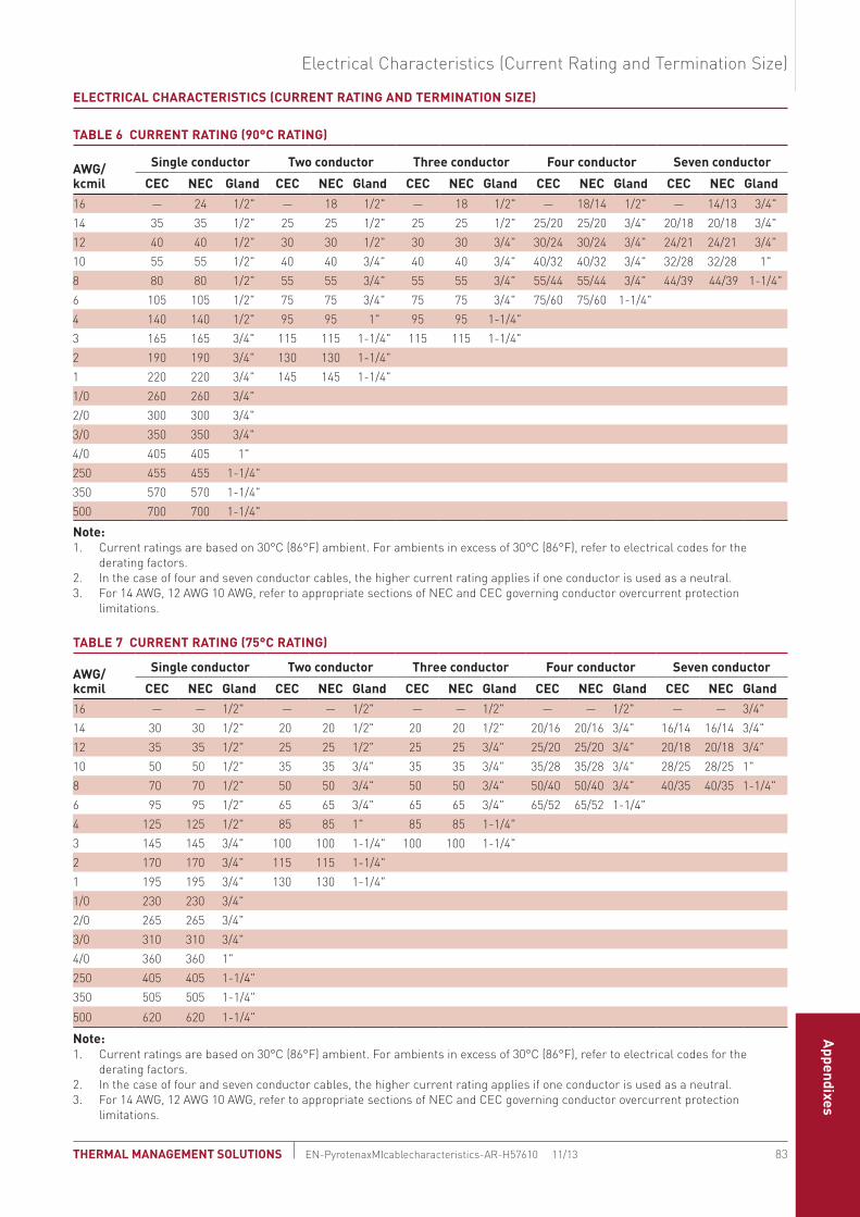
Self-Reg-ulating Cables
Power-
Limiting
Cables
Mineral
Insulated Cables
Longline H
eatingRTB Tubing Bundles
Tank Heat-
ingSnow
and Ice
Control and M
onitoringH
eat-Trace Panels
Engineered Products
Steam-
Tracing System
s
Technical Data Sheets
AppendixesFire-R
ated CablesSpace Saving Cable System
Service Entrance Cable System
sCodes and Standards
Technical Data Sheets
Appendixes
eLeCtRICAL CHARACteRIstICs (CURRent RAtInG And teRMInAtIon sIze)
tAbLe 6 CURRent RAtInG (90°C RAtInG)
AwG/ kcmil
single conductor two conductor three conductor Four conductor seven conductor
CeC neC Gland CeC neC Gland CeC neC Gland CeC neC Gland CeC neC Gland16 — 24 1/2" — 18 1/2" — 18 1/2" — 18/14 1/2" — 14/13 3/4"14 35 35 1/2" 25 25 1/2" 25 25 1/2" 25/20 25/20 3/4" 20/18 20/18 3/4"12 40 40 1/2" 30 30 1/2" 30 30 3/4" 30/24 30/24 3/4" 24/21 24/21 3/4"10 55 55 1/2" 40 40 3/4" 40 40 3/4" 40/32 40/32 3/4" 32/28 32/28 1"8 80 80 1/2" 55 55 3/4" 55 55 3/4" 55/44 55/44 3/4" 44/39 44/39 1-1/4"6 105 105 1/2" 75 75 3/4" 75 75 3/4" 75/60 75/60 1-1/4"4 140 140 1/2" 95 95 1" 95 95 1-1/4"3 165 165 3/4" 115 115 1-1/4" 115 115 1-1/4"2 190 190 3/4" 130 130 1-1/4"1 220 220 3/4" 145 145 1-1/4"1/0 260 260 3/4"2/0 300 300 3/4"3/0 350 350 3/4"4/0 405 405 1"250 455 455 1-1/4"350 570 570 1-1/4"500 700 700 1-1/4"
note:1. Current ratings are based on 30°C (86°F) ambient. For ambients in excess of 30°C (86°F), refer to electrical codes for the
derating factors.2. In the case of four and seven conductor cables, the higher current rating applies if one conductor is used as a neutral.3. For 14 AWG, 12 AWG 10 AWG, refer to appropriate sections of NEC and CEC governing conductor overcurrent protection
limitations.
tAbLe 7 CURRent RAtInG (75°C RAtInG)
AwG/kcmil
single conductor two conductor three conductor Four conductor seven conductor
CeC neC Gland CeC neC Gland CeC neC Gland CeC neC Gland CeC neC Gland16 — — 1/2" — — 1/2" — — 1/2" — — 1/2" — — 3/4"14 30 30 1/2" 20 20 1/2" 20 20 1/2" 20/16 20/16 3/4" 16/14 16/14 3/4"12 35 35 1/2" 25 25 1/2" 25 25 3/4" 25/20 25/20 3/4" 20/18 20/18 3/4"10 50 50 1/2" 35 35 3/4" 35 35 3/4" 35/28 35/28 3/4" 28/25 28/25 1"8 70 70 1/2" 50 50 3/4" 50 50 3/4" 50/40 50/40 3/4" 40/35 40/35 1-1/4"6 95 95 1/2" 65 65 3/4" 65 65 3/4" 65/52 65/52 1-1/4"4 125 125 1/2" 85 85 1" 85 85 1-1/4"3 145 145 3/4" 100 100 1-1/4" 100 100 1-1/4"2 170 170 3/4" 115 115 1-1/4"1 195 195 3/4" 130 130 1-1/4"1/0 230 230 3/4"2/0 265 265 3/4"3/0 310 310 3/4"4/0 360 360 1"250 405 405 1-1/4"350 505 505 1-1/4"
500 620 620 1-1/4"
note:1. Current ratings are based on 30°C (86°F) ambient. For ambients in excess of 30°C (86°F), refer to electrical codes for the
derating factors.2. In the case of four and seven conductor cables, the higher current rating applies if one conductor is used as a neutral.3. For 14 AWG, 12 AWG 10 AWG, refer to appropriate sections of NEC and CEC governing conductor overcurrent protection
limitations.
Electrical Characteristics (Current Rating and Termination Size)
83 THERMAL MANAGEMENT SOLUTIONS EN-PyrotenaxMIcablecharacteristics-AR-H57610 11/13

tAbLe 8 CondUCtoR ResIstAnCe (oHMs/1000 Ft) At 25°C (77°F)
AWG/kcmil 18 16 14 12 10 8 6 4 3 2 1 1/0 2/0 3/0 4/0 250 350 500
Nominal DC resistance 6.51 4.09 2.58 1.62 1.02 0.641 0.403 0.253 0.201 0.159 0.126 0.100 0.079 0.063 0.050 0.042 0.030 0.021
Maximum DC resistance 7.05 4.25 2.73 1.72 1.08 0.680 0.427 0.269 0.213 0.169 0.134 0.106 0.084 0.067 0.052 0.045 0.032 0.022
temperature Coefficient of Resistance
The resistance of copper conductors will increase with temperature in accordance with the following formula:
RT = R [1+.0039 (T-25)] R = resistance at 25°C
RT = resistance at new temperature T = new temperature (°C)
tAbLe 9 noMInAL CAPACItAnCe And IndUCtAnCe (systeM 1850 MI CAbLe)
AwG/kcmil
Capacitance (µF/1000 ft) Inductance (µH/1000 ft)
single conductor Multiconductor single conductor Multiconductor
600 V 600 V 600 V 600 V16 0.055 0.043 90 103
14 0.064 0.049 80 99
12 0.076 0.058 70 91
10 0.082 0.067 66 86
8 0.101 0.079 56 81
6 0.119 0.095 50 77
4 0.128 0.101 47 73
3 0.130 0.102 47 67
2 0.167 0.108 40 65
1 0.173 0.107 39 65
1/0 0.211 35
2/0 0.205 35
3/0 0.232 33
4/0 0.272 30
250 0.268 31
350 0.283 30
500 0.281 30
PYROTENAX MI CABLE CHARACTERISTICS
THERMAL MANAGEMENT SOLUTIONSEN-PyrotenaxMIcablecharacteristics-AR-H57610 11/1384

Fire-Rated Cables
Space Saving Cable System
Service Entrance Cable System
sCodes and Standards
Technical Data Sheets
Appendixes
To calculate voltage drop for a three-phase line-to-line circuit, the following formula should be used with the appropriate Factor “A” from Table 2 or Table 3. These calculations are simplified for ease of use and give approximate results.
Voltage drop = (Run length) X (Circuit current) X (Temp. const.) X (Factor “A”) 1000
Percentage voltage drop = Voltage drop X 100 Circuit voltage
note: Use the calculated load (not the fuse or breaker rating) to determine voltage drop.
tAbLe 1 teMPeRAtURe ConstAnt
Cable at full rated current 1.00
Cable at 3/4 rated current 0.95
Cable at 1/2 rated current 0.91
Cable at 1/4 rated current 0.88
Note that these calculated voltage drops represent the line-to-line voltage drop in a three-phase system. To estimate the single-phase voltage drop, multiply the three-phase line-to-line voltage drop by 1.16. In those rare instances where the line-to-neutral voltage drop in a three-phase system is required, multiply the three-phase line-to-line voltage drop by 0.58.
tAbLe 2 VoLtAGe dRoP FACtoR “A” FoR sInGLe CondUCtoR CAbLe In tReFoIL, 90°C CondUCtoR teMPeRAtURe
Cable reference
Conductor size AwG/kcmil
Lagging power factor in percent
100 95 90 85 80 75 30
1/6-340 6 0.894 0.867 0.892 0.790 0.749 0.708 0.323
1/4-402 4 0.576 0.565 0.543 0.519 0.494 0.469 0.225
1/3-449 3 0.45 0.444 0.429 0.411 0.393 0.373 0.187
1/2-449 2 0.355 0.353 0.341 0.328 0.314 0.299 0.154
1/1-496 1 0.285 0.286 0.278 0.268 0.257 0.246 0.132
1/1/0-512 1/0 0.226 0.229 0.223 0.216 0.208 0.200 0.111
1/2/0-580 2/0 0.181 0.187 0.183 0.178 0.173 0.166 0.098
1/3/0-621 3/0 0.146 0.153 0.151 0.148 0.144 0.139 0.086
1/4/0-684 4/0 0.119 0.127 0.126 0.124 0.121 0.118 0.077
1/250-746 250 0.104 0.112 0.112 0.111 0.109 0.107 0.073
1/350-834 350 0.077 0.086 0.088 0.087 0.087 0.085 0.063
1/500-1000 500 0.061 0.071 0.073 0.073 0.073 0.073 0.058
85 THERMAL MANAGEMENT SOLUTIONS EN-PyrotenaxMIvoltagedrop-AR-H57611 11/13
PYROTENAX MI VOLTAGE DROP CALCULATIONS

tAbLe 3 VoLtAGe dRoP FACtoR “A” FoR tHRee CondUCtoR CAbLe, 90°C CondUCtoR teMPeRAtURe
Cable reference
Conductor size AwG
Lagging power factor in percent
100 95 90 85 80 75 30
3/14-387 14 5.746 5.463 5.179 4.895 4.611 4.328 1.766
3/12-480 12 3.600 3.424 3.248 3.071 2.895 2.718 1.122
3/10-480 10 2.279 2.169 2.058 1.947 1.836 1.725 0.721
3/8-590 8 1.459 1.389 1.320 1.250 1.180 1.110 0.475
3/6-621 6 0.920 0.877 0.834 0.790 0.747 0.704 0.309
3/4-746 4 0.591 0.565 0.538 0.511 0.484 0.457 0.210
3/3-834 3 0.476 0.455 0.434 0.413 0.392 0.371 0.175
example:
Run length 500'Voltage drop = 500 x 100 x 0.91 x 0.216 = 9.8 V 1000
Percent voltage drop = 9.8 x 100 = 1.63% 600
Circuit current 100 A
Voltage 600 V, three-phase
Power factor 85%
Initial cable size
1/0 AWG
If the voltage drop is over the desired limit, select a larger cable and repeat. Alternatively, use parallel runs of smaller cable, calculating voltage drop on the reduced current carried by each run.
For fire pump motors, check that the voltage drop does not exceed 5% @ 115% rated current, and does not equal or exceed 15% at locked rotor current, including the drop in the motor/generator.
note: Ensure all the applicable requirements of national and local electrical codes are met.
PYROTENAX MI VOLTAGE DROP CALCULATIONS
THERMAL MANAGEMENT SOLUTIONSEN-PyrotenaxMIvoltagedrop-AR-H57611 11/1386

Fire-Rated Cables
Space Saving Cable System
Service Entrance Cable System
sCodes and Standards
Technical Data Sheets
Appendixes
CoPPeR sHeAtH CAbLes
Pyrotenax unjacketed MI cables are nonflammable; when exposed to fire conditions, they will not burn, contribute fuel, or emit flammable or toxic gases.
The temperature limit of the cable for continuous operation is determined only by the progressive oxidation temperature of the copper sheath, 250°C (482°F) in normal atmosphere.
For higher temperature applications, the cable may be exposed to continuous tempera-tures above 250°C (482°F); however, a reduced sheath life should be anticipated, as shown in Table 1.
tAbLe 1 deCReAse In CoPPeR sHeAtH tHICkness As A FUnCtIon oF tIMe At VARIoUs teMPeRAtURes
decrease in sheath thickness, mils*
years at 250°C (482°F)
years at 400°C (752°F)
Hours at 800°C (1472°F)
1 2.57 0.0583 0.259
2 10.3 0.233 1.04
5 64.3 1.46 6.48
10 257 5.83 25.9
*1 mil = 0.001 inch
sHeAtH teMPeRAtURe RIse
The following graphs show the expected sheath temperature rise on MI cables under free air conditions when installed according to the appropriate product installa-tion instructions. Note that the curves are based on the cable being in free air at 25°C (77°F) and sheath temperatures will be lower if the cables are embedded in a medium which has a quenching or cooling effect. Conversely, if the cables are sur-rounded by a medium which acts as a heat insulator, the sheath temperatures will be higher for a given current.
87 THERMAL MANAGEMENT SOLUTIONS EN-PyrotenaxMItemperaturecharacteristics-AR-H57612 11/13
PYROTENAX MI TEMPERATURE CHARACTERISTICS

302F(150C)
1/16
-215
1/14
-230
1/12
-246
1/10
-277
1/8-
298
1/6-
340
1/4-
402
1/3-
449
1/2-
449
1/1-
496
1/1/
0-51
2
1/2/
0-58
0
1/3/
0-62
1
1/4/
0-68
4
1/25
0-74
6
1/35
0-83
41/
1000
-500
212F(100C)
Tem
pera
ture
Ris
e
Conductor Currents (Amps)
122F(50C)
32F(0C)
0 100 200 300 400 500 700 800600
16 A
WG
14 A
WG
12 A
WG
10 A
WG
8 AW
G
6 AW
G
4 AW
G
3 AW
G
2 AW
G
1 AW
G
1/0
AWG
2/0
AWG
3/0
AWG
4/0
AWG
250
kcm
il
350
kcm
il50
0 kc
mil
Graph 1 sheath temperature rise for 600 V MI single conductor cables in free air conditions
Graph 2 sheath temperature rise for 300 V and 600 V MI two conductor cables in free air conditions
2/18
-230
DF
2/16
-246
DF
2/16
-340
2/14
-277
DF
2/14
-371
2/12
-319
DF
2/12
-402
2/10
-449
2/10
-371
DF
2/8-
512
2/6-
590
2/4-
684
Tem
pera
ture
Ris
e
Conductor Currents (Amps)
0 20 40 60 80 100 140 160 180 200120
302F(150C)
212F(100C)
122F(50C)
32F(0C)
16 A
WG
18 A
WG
14 A
WG
12 A
WG
10 A
WG
8 AW
G
6 AW
G
4 AW
G
PYROTENAX MI TEMPERATURE CHARACTERISTICS
THERMAL MANAGEMENT SOLUTIONSEN-PyrotenaxMItemperaturecharacteristics-AR-H57612 11/1388

Fire-Rated Cables
Space Saving Cable System
Service Entrance Cable System
sCodes and Standards
Technical Data Sheets
Appendixes
Graph 3 sheath temperature rise for 300 V and 600 V MI three conductor cables in free air conditions
Graph 4 sheath temperature rise for 300 V and 600 V MI four conductor cables in free air conditions
3/18
-246
DF
3/16
-355
3/14
-309
DF
3/14
-387
Conductor Currents (Amps)0 20 40 60 80 100 140 160 180 200120
18 A
WG
16 A
WG
3/12
-480
12 A
WG
3/8-
590
8 AW
G
3/6-
621
6 AW
G
3/4-
746
4 AW
G
14 A
WG
3/10
-387
DF
3/10
-480
10 A
WG
Tem
pera
ture
Ris
e
302F(150C)
212F(100C)
122F(50C)
32F(0C)
Conductor Currents (Amps)
0 20 40 60 80 100 120
Tem
pera
ture
Ris
e
302F(150C)
212F(100C)
122F(50C)
32F(0C)
4/16
-290
DF
4/16
-387
4/14
-465
14 A
WG
4/10
-590
10 A
WG
4/8-
590
8 AW
G
4/6-
730
6 AW
G
16 A
WG
4/12
-371
DF
4/12
-465
12 A
WG
Sheath Temperature Rise
89 THERMAL MANAGEMENT SOLUTIONS EN-PyrotenaxMItemperaturecharacteristics-AR-H57612 11/13

Graph 5 sheath temperature rise for 300 V and 600 V MI seven conductor cables in free air conditions
note: Values are based on the Neher-McGrath calculation, AIEE 1957.
termination temperature Limits
There are several terminations available for sealing and terminating Pyrotenax MI cables. The temperature limit for these terminations is dependent on the sealing material and sleeving used. Refer to the product data sheets for additional information.
Conductor Currents (Amps)
0 20 40 60 80 100 120
Tem
pera
ture
Ris
e
302F(150C)
212F(100C)
122F(50C)
32F(0C)
7/16
-344
DF
7/16
-449
7/18
-298
DF
18 A
WG
7/10
-621
10 A
WG
16 A
WG
7/14
-387
DF
7/14
-496
14 A
WG
7/12
-449
DF
7/12
-543
12 A
WG
PYROTENAX MI TEMPERATURE CHARACTERISTICS
THERMAL MANAGEMENT SOLUTIONSEN-PyrotenaxMItemperaturecharacteristics-AR-H57612 11/1390

Fire-Rated Cables
Space Saving Cable System
Service Entrance Cable System
sCodes and Standards
Technical Data Sheets
Appendixes
On occasion it is necessary to provide for expansion of a cable operating under abnormal temperature conditions, or to prevent mechanical damage which may result from the relative movement of different items of equipment traversed by a cable.
Conditions encountered in commercial applications can be satisfied by providing, between securing clips or other fixation methods, a right angle bend (Fig. 1), two right angle bends (Fig. 2), or one semicircular bend and two 45° angle bends (Fig. 3) in the cable, whichever is most appropriate for a particular installation.
For MI cable the bending radius should not be less than six times the cable diameter for cables up to 0.75 inch (19 mm) diameter and 12 times the cable diameter for cables greater than 0.75 inch (19 mm) diameter. Where the termination is subject to vibration, an expansion loop as shown in Fig. 4 is recommended.
Fig. 1 single right angle bend
Fig. 2 two right angle bends
Fig. 3 one semicircular bend
Fig. 4 expansion loop on termination end
Assumedfixed end
Movement assumed to be in the direction of the arrow
Movement assumed to be in the direction of the arrow
Assumed fixed end
Movement assumed to be in the direction of the arrow
91 THERMAL MANAGEMENT SOLUTIONS EN-CommercialWiringCableExpansionVibration-AR-H57613 11/13
PYROTENAX MI CABLE EXPANSION AND VIBRATION

Copper sheathed cables are noted for their general resistance to chemical corrosion as compared to most other metals. However, as with all metals, there are certain environments which will be detrimental.
Copper is susceptible to oxidizing acids such as nitric, sulfurous, and concentrated sulfuric acid. Similarly, it is attacked by oxidizing salts. Ions that are susceptible to reduction include ferric, stannic, and mercuric. Although resistant to attack by most dry gases, it is susceptible to corrosion by wet fluorine, chlorine, bromine, iodine, and ammonia. Sulfur compounds have a strong tendency to attack it. For applications involving corrosion, contact Pentair Thermal Management or consult a corrosion handbook.
When copper is in contact with a metal more active in electrochemical potential, through an electrolyte, corrosion of the metal may be stimulated. The common metals most likely to be affected are aluminum, magnesium, zinc, and, in some cases, galvanized steel. In actual practice the surface area of the cable or cathode is so small in comparison to the anodic metal that very little corrosion will take place. For example, the cable is often used on aluminum and galvanized steel towers without any serious corrosion problem occurring. Again, the surface area is so small in comparison that, for most applications, this type of corrosion can be ignored.
Stress corrosion cracking is a combination of both stress and corrosion which causes metal embrittlement and cracking. Since the cables must be bent during installation, they invariably contain sufficient surface stress so that when exposed to particular corrosive agents, cracking can occur. For this type of corrosion with copper, the only known corrosive agent is ammonia or ammonia-bearing materials called amines. For ammonia to cause this type of cracking, traces of moisture and carbon dioxide, as normally found in the atmosphere, are also required. This type of corrosion cracking has been encountered where urine has been in contact with the cable during installation. There is very little apparent surface corrosion; however, the cable sheath becomes brittle and may eventually crack with the slightest stress. In any case, this particular type of corrosion has been relatively rare.
Where the copper sheath could be corroded, an extruded HDPE polymer jacket can be supplied.
tAbLe 1 JACket MAteRIAL AVAILAbLe FoR MI CAbLe
Jacket material
typical thicknessFlammability (AstM d635)
Maximum operating temperature (continuous)
Minimum installation temperature(in) (mm)
Polyethylene 0.040 1.0 FT4 120°C (248°F) –40°C (–40°F)
The following table lists various materials and their resistance to chemicals under average conditions. However, it is intended only as a guide and does not imply a guarantee due to the number of variable conditions which may be encountered.
THERMAL MANAGEMENT SOLUTIONSEN-CopperSheathedCableCorrosion-AR-H57614 11/1392
COPPER SHEATHED CABLE AND CORROSION

Fire-Rated Cables
Space Saving Cable System
Service Entrance Cable System
sCodes and Standards
Technical Data Sheets
Appendixes
tAbLe 2 CoRRosIon ResIstAnCe tAbLe
Material
Chemical Copp
er
Cupr
o n
icke
l
Allo
y 82
5
304
stai
nles
s
Inco
nel 6
00
Poly
ethy
lene
PVC
Acetic Acid S E E S S S S
Acetic Anhydride S S E S S N N
Acetone S E E E E N N
Acetylene N N E E S N E
Alcohols E E E E – S E
Alum S E E N S E E
Alumina E E E N N – E
Aluminum Chloride S S E N – E E
Aluminum Hydroxide E E E E – S E
Aluminum Sulfate S E E N S E E
Ammonia, Absolutely dry N E E E E E E
Ammonia, moist N S E E E N N
Ammonium Hydroxide N S E E E E E
Ammonium Chloride S S E N S E E
Ammonium Nitrate N S E E S E E
Ammonium Sulfate S S E S S E E
Amyl Acetate S S E E E N N
Amyl Alcohol E E E – – E S
Aniline N N E E E S N
Aniline Dyes N N E E E N N
Asphalt E E E E – – E
Atmosphere, Industrial E E E E E E E
Atmosphere, Marine S E E N S E E
Atmosphere, Rural E E E E E E E
Barium Carbonate E E E E E E E
Barium Chloride S S E S S E E
Barium Hydroxide N E E S E E E
Barium Sulfate N E E E – E E
Barium Sulfide N S E E – E S
Beer S E E E E E E
Beet Sugar Syrups E E E E – – E
Benzine E E E E E N N
Benzoic Acid E E E S – E E
Benzol E E E E E E N
Black Liquor, Sulphate Process S S E S N – E
Bleaching Powder, wet S S S N N – N
Borax S E E E E E E
Bordeaux Mixture E E – E – – –
Boric Acid S E E S E E E
Ratings: E – The material should be suitable under most conditions. S – The material offers fair corrosion resistance. It may be considered in place of a material
with an “E” rating when some property other than corrosion resistance governs its use. N – The material is not suitable.
Copper Sheathed Cable and Corrosion
93 THERMAL MANAGEMENT SOLUTIONS EN-CopperSheathedCableCorrosion-AR-H57614 11/13

tAbLe 2 CoRRosIon ResIstAnCe tAbLe
Material
Chemical Copp
er
Cupr
o n
icke
l
Allo
y 82
5
304
stai
nles
s
Inco
nel 6
00
Poly
ethy
lene
PVC
Brines S E E – S E E
Bromine, dry E E E N – N N
Bromine, moist S S S N E N N
Butane E E E E E – E
Butyl Alcohol S S E – – E S
Butyric Acid S S E E S N N
Calcium Bisilite S S E S N S E
Calcium Chloride S S E E E E E
Calcium Hydroxide S E E S E E E
Calcium Hypochlorite S S S N S E E
Cane Sugar Syrups E E E E E – E
Carbolic Acid S S E S E E E
Carbon Dioxide, dry E E E E E E E
Carbon Dioxide, moist S E E S E E E
Carbonated Water S E E E – E –
Carbonated Beverages S E E E E E E
Carbon Disulfide N – E E – N N
Carbon Tetrachloride, dry E E E E E N S
Carbon Tetrachloride, moist S E E S E N N
Castor Oil E E E E E E E
Chlorine, dry S E E S – S N
Chlorine, moist N S S N N N N
Chloracetic Acid S S E N S – S
Chloroform, dry E E E E E N N
Chromic Acid N N E N N S S
Cider S S E S – E E
Citric Acid S E E S – E E
Coffee E E E E – – –
Copper Chloride N N E S N E E
Copper Nitrate N N E E N E E
Copper Sulfate S E E E S E E
Corn Oil E E E E E E E
Cottonseed Oil E E E E E E E
Creosote S E E N – N N
Crude Oil E E E E – – –
Ethers E E E E E N N
Ethyl Acetate E E E S S N N
Ethyl Alcohol E E E E – E E
Ethyl Chloride S S E E E N N
Ratings: E – The material should be suitable under most conditions. S – The material offers fair corrosion resistance. It may be considered in place of a material
with an “E” rating when some property other than corrosion resistance governs its use. N – The material is not suitable.
COPPER SHEATHED CABLE AND CORROSION
THERMAL MANAGEMENT SOLUTIONSEN-CopperSheathedCableCorrosion-AR-H57614 11/1394

Fire-Rated Cables
Space Saving Cable System
Service Entrance Cable System
sCodes and Standards
Technical Data Sheets
Appendixes
tAbLe 2 CoRRosIon ResIstAnCe tAbLe
Material
Chemical Copp
er
Cupr
o n
icke
l
Allo
y 82
5
304
stai
nles
s
Inco
nel 6
00
Poly
ethy
lene
PVC
Ethylene Glycol E E E E – E S
Ferric Chloride N N S N N E E
Ferric Sulfate N N E E E E E
Ferrous Chloride N S S N N E E
Ferrous Sulfate S S E S – E E
Formaldehyde S E E S E E S
Formic Acid S S E N S E N
Freon E E E E – E E
Fruit Juices S S E E E E E
Fuel Oil S E E N S N S
Furfural E E E E S N N
Gasoline E E E E E N N
Gelatine E E E E E – E
Glucose E E E E E E E
Glue E E E – – – –
Glycerine S E E E E E E
Hydrobromic Acid N N S N N E E
Hydrocarbons, Pure E E E E E E E
Hydrochloric Acid N N S N N E E
Hydrocyanic Acid, dry S S S N S S N
Hydrofluosilicic Acid S S E N S – S
Hydrogen E E E E – E E
Hydrogen Peroxide N N E S E S E
Hydrogen Sulfide, dry N E E S S E E
Hydrogen Sulfide, moist N N E S S E E
Kerosene E E E E E N E
Lacquers E E E S – – –
Lacquer Solvents E E E – – – –
Lactic Acid S E E S S E S
Lime S E E S – – E
Line–Sulfur N N – E – – E
Linseed Oil S S E E S S E
Magnesium Chloride S S E S E E E
Magnesium Hydroxide E E E E S E E
Magnesium Sulfate S E E E E E E
Mercury N N E E E E E
Mercury Salts N N E E S E E
Methyl Alcohol S S E E E E S
Methyl Chloride, dry S E E E E N N
Ratings: E – The material should be suitable under most conditions. S – The material offers fair corrosion resistance. It may be considered in place of a material
with an “E” rating when some property other than corrosion resistance governs its use. N – The material is not suitable.
Copper Sheathed Cable and Corrosion
95 THERMAL MANAGEMENT SOLUTIONS EN-CopperSheathedCableCorrosion-AR-H57614 11/13

tAbLe 2 CoRRosIon ResIstAnCe tAbLe
Material
Chemical Copp
er
Cupr
o n
icke
l
Allo
y 82
5
304
stai
nles
s
Inco
nel 6
00
Poly
ethy
lene
PVC
Milk S E E E E E E
Mine Water N – E E – E E
Natural Gas E E E E E – –
Nitric Acid N N E S N S N
Nitrogen E E E – S – –
Oleic Acid S S E N E N E
Oxalic Acid S S E N E E E
Oxygen E E E E E – E
Palmitic Acid S S E N – S E
Paraffin E E E E – – –
Phosphoric Acid S S E N S S E
Potassium Carbonate E E E E E E E
Potassium Chloride S E E N E E E
Potassium Chromate E E E S E E E
Potassium Cyanide N N E E E E E
Potassium Dichromate, Acid N N E E S E E
Potassium Hydroxide S E E S E E E
Potassium Sulfate E E E E E E E
Propane E E E E – – E
Rosin S E E E – – –
Sea Water S E E N S E E
Sewage E E E – – E E
Silver Salts N N E E – E E
Soap Solutions E E E E – E E
Sodium Bicarbonate E E E S S E E
Sodium Bisulfate S E E S S E E
Sodium Bisulfite S S E S S E E
Sodium Carbonate E E E E E E E
Sodium Chloride S E E N E E E
Sodium Chromate E E E – – – –
Sodium Cyanide N N E E – E E
Sodium Dichromate, Acid N N E – – E E
Sodium Hydroxide(Caustic Soda) S E E S E E E
Sodium Hypochlorite S S S N N E E
Sodium Nitrate S E E S E E E
Sodium Peroxide S S E E E – E
Sodium Phosphate E E E E E – E
Sodium Silicate S E E E E – –
Sodium Sulfate E E E E S E E
Ratings: E – The material should be suitable under most conditions. S – The material offers fair corrosion resistance. It may be considered in place of a material
with an “E” rating when some property other than corrosion resistance governs its use. N – The material is not suitable.
COPPER SHEATHED CABLE AND CORROSION
THERMAL MANAGEMENT SOLUTIONSEN-CopperSheathedCableCorrosion-AR-H57614 11/1396

Fire-Rated Cables
Space Saving Cable System
Service Entrance Cable System
sCodes and Standards
Technical Data Sheets
Appendixes
tAbLe 2 CoRRosIon ResIstAnCe tAbLe
Material
Chemical Copp
er
Cupr
o n
icke
l
Allo
y 82
5
304
stai
nles
s
Inco
nel 6
00
Poly
ethy
lene
PVC
Sodium Sulfide N N E N S E E
Sodium Sulfite S S E E S E E
Sodium Thiosulfate N N E E E E E
Steam E E E E – E –
Stearic Acid S E E S E E E
Sugar Solutions E E E – – E E
Sulfur, dry S E E S S E E
Sulfur, molten N N S S N – N
Sulfur Chloride, dry E E E S – – E
Sulfur Dioxide, dry E E E E E S E
Sulfur Dioxide, moist S N E S N S N
Sulfur Trioxide, dry E E E – – E E
Sulfuric Acid, 8O–95% N S E N N N S
Sulfuric Acid, 40–80% N N E N N N E
Sulfuric Acid, 40% N S E N S E E
Sulfurous Acid S N E N N E E
Tannic Acid S E E E – E E
Tar E E E – – – –
Tartaric Acid S E E S S S E
Toluene E E E E E N N
Trichloracetic Acid S S E E – – –
Trichlorethylene, dry E E E S S N N
Trichlorethylene, moist S E E S S N N
Turpentine E E E S E N E
Varnish E E E E – – –
Vinegar S E E S E E E
Water, Potable S E E E – E E
Zinc Chloride S S E N – E E
Zinc Sulfate S E E S – E E
Ratings: E – The material should be suitable under most conditions. S – The material offers fair corrosion resistance. It may be considered in place of a material
with an “E” rating when some property other than corrosion resistance governs its use. N – The material is not suitable.
disclaimer: Information is believed to be reliable and is based on generally available technical literature. However, no guarantee is expressed or implied. User must verify product suitability for each application.
Copper Sheathed Cable and Corrosion
97 THERMAL MANAGEMENT SOLUTIONS EN-CopperSheathedCableCorrosion-AR-H57614 11/13

sInGLe CondUCtoR CAbLe
Single conductor cables present certain application considerations that do not arise in multiconductor cable installations. These considerations apply to both single con-ductor mineral insulated copper sheath cables and polymer insulated cables having an aluminum or copper armor or sheath. Sheath voltages in single conductor cables arise as a result of three physical principles:
All electric currents, AC or dC, generate a magnetic field
As shown in Fig. 1, the magnetic field generated by the flow of current surrounds the conductor completely and radiates laterally outward, becoming weaker with increas-ing distance. In the case of a DC circuit, the magnetic field is constant and has a strength determined by, among other factors, the magnitude of the DC current.
Neither the strength nor direction of the magnetic field is constant in the AC current case. Rather, the field reacts to the current’s changing nature by itself alternating in strength and direction.
Battery
Direction of currentflow through conductor
Lines of magnetic forcesurround primary conductor
Arrows give direction of compass needle north at that point
Primary conductor
Fig. 1 Magnetic field generated by current flow
Faraday’s Law of Induction
Faraday found that a changing magnetic field will induce a voltage by which a current can flow. A magnetic field generated by a DC current cannot induce a steady-state voltage, as the field does not change. An AC current, with its attendant alternating magnetic field will, however, induce a voltage which, if a closed path is available, will cause a current to flow.
Lenz’s Law
Lenz added to Faraday’s work on the induction principle by developing a theory that explained the direction or polarity of the induced voltage. He found that the direction of the induced current, which flows as a result of the induced voltage, is such as to oppose the magnetic field which created it (see Fig. 2).
THERMAL MANAGEMENT SOLUTIONSEN-CopperSheathedCableSheathCurrents-AR-H57615 11/1398
COPPER SHEATHED CABLE — SHEATH CURRENTS

Fire-Rated Cables
Space Saving Cable System
Service Entrance Cable System
sCodes and Standards
Technical Data Sheets
Appendixes
Fig. 2 Lenz’s Law: opposing polarity of magnetic fields
Fig. 3 Induced current in sheath
Fig. 3 shows the net result of the induction effect as applied to any metal-sheathed, single conductor cable.
The 60 Hz alternating current flowing in the conductor itself (termed primary cur-rent) generates a changing magnetic field which surrounds the entire cable assem-bly. That field then acts to induce a voltage in the metal sheath of the cable. If the metal sheath is grounded at more than one point, a closed circuit is available and the induced sheath voltage will cause an electric current to circulate through the sheath and grounding system.
The direction of the circulating sheath current is at all times in opposition to the flow in the primary conductor as a result of Lenz’s Law.
Sheath voltages cannot be prevented. They arise from Faraday’s Induction Principle and can be minimized only by proper grounding of the cable sheath. That, however, leads to sheath circulating currents as multiple grounds provide closed paths for sheath current to flow.
Sheath current magnitude is not dependent on cable length. Rather, it is a func-tion of primary current magnitude, cable diameter, and sheath material. As length increases, so does the induced sheath voltage, and, in a compensatory manner, the total sheath electrical resistance. Since both voltage and resistance are directly pro-portional to length, the resulting sheath current, by Ohm’s law, remains constant.
Sheath voltages can reach significant values, usually in the order of a few volts to tens of volts. Although not normally life threatening, the potentials can be sufficient to cause sparking under certain circumstances and can pose a serious danger in explosive atmospheres (Class I, II, or III hazardous locations). Even in nonhazardous environments, incidents of sheath-to-ground sparking can be unnerving to mainte-nance personnel and should be avoided.
Proper grounding of the sheath will minimize induced sheath voltages and prevent occurrences of sparking, but circulating currents will flow through the metal sheath via the grounding paths and can produce 12R heating of the cable sheath itself. In ad-dition, the energy loss involved in producing the sheath heating effects are manifest in slightly increased voltage drop on the circuit that is supplied by the cables in ques-
AA
Magnetic fieldcreated to opposethe primary field
Primarymagneticfield
Direction of induced current flow
Primarycurrentflow
If a closed circuit is available, an induced orsecondary current will flow in this direction
Sheath voltageavailable to drive current
Single Conductor Cable
99 THERMAL MANAGEMENT SOLUTIONS EN-CopperSheathedCableSheathCurrents-AR-H57615 11/13

tion. (Sheath heating due to circulating currents can be a serious problem. Derating may be necessary if conductor temperatures are to be kept to less than 90°C.)
Sheath voltages and currents tend to increase with increased spacing between the conductors of a circuit. This effect results from the concept of field cancellation: the closer together the conductors, the better the cancellation of the fields and the weaker the overall resulting magnetic field which surrounds all circuit conductors. Refer to Fig. 4.
Maximum cancellation occurs, of course, when the cables’ sheaths are in actual contact. However, mutual heating effects of each conductor on the others must then be considered.
Fig. 4 overlapping fields result in weaker magnetic field
otHeR MAGnetIC eFFeCts
Induced voltages resulting from alternating magnetic fields are the cause of a sec-ond type of circulating current. These currents (termed “eddy” currents) flow in the metal plates through which single conductor cables may enter a switchgear enclo-sure and result when voltages that generate secondary magnetic fields are induced by Faraday’s Law. Refer to Fig. 5.
Fig. 5 single conductor feeders with magnetic fields
Eddy currents do contribute to heating of the metal plates through 12R losses. In this type of application, however, the losses tend to be low as a result of the rela-tively small cross-sectional area of the metal enclosure and need not be directly addressed. (In other applications, like those involving ferromagnetic cores, eddy cur-rent losses can be very large and are an important factor in total “iron” losses.)
Hysteresis loss is the third and final type of heating effect arising as a result of the changing magnetic field surrounding a single conductor cable.
Here, the magnetic field (alternating at two times 60 Hz) creates a similarly alter-nating magnetic field within the ferromagnetic metal (normally steel) making up the wall or plate through which the conductors enter an enclosure. In each cycle of magnetization, the molecules comprising the structure realign themselves in the
Current flowinto sheet
Current flowout of sheet
Resulting weakermagnetic field
Currentflow down
Currentflow up
Eddycurrentflow
Lines ofmagnetic flux
Platesteel 1/4"
COPPER SHEATHED CABLE — SHEATH CURRENTS
THERMAL MANAGEMENT SOLUTIONSEN-CopperSheathedCableSheathCurrents-AR-H57615 11/13100
Fire-Rated Cables
Space Saving Cable System
Service Entrance Cable System
sCodes and Standards
Technical Data Sheets
Appendixes
direction of the impressed field, and it is this realignment, with attendant frictional losses, that results in hysteresis heating.
The magnitude of the hysteresis loss is determined to a large degree by the mag-netic flux density which exists within the metal. Magnetic flux density is a measure of the strength of the magnetic field; losses can be greatly reduced by limiting the flux density.
Note that hysteresis losses can occur only in ferromagnetic metals (e.g. iron, steel, nickel) as only these materials have magnetic permeabilities great enough to allow significant flux densities to develop. It is for this reason that metal-sheathed single conductor cables always incorporate sheaths of nonmagnetic material, copper in the case of MI cable, and copper or aluminum in the case of armored cable.
Steps can be taken to prevent hysteresis heating of cable entry plates:
• A nonmetallic plate made of an insulating material can be used in place of the usual steel entry.
• A replacement plate of nonmagnetic material (aluminum or brass) can be in-stalled. Only ferromagnetic metals are subject to hysteresis heating; other metals cannot be magnetized and do not suffer losses.
• An air gap can be introduced into the magnetic circuit in which the magnetic flux exists. Its effect, because air has a very low magnetic permeability, is to drasti-cally reduce the flux density in much the same manner as a large resistance lim-its current flow in an electric circuit. As discussed earlier, hysteresis losses are greatly dependent upon the magnitude of the flux density and they are, therefore, significantly lowered.
InstALLAtIon ReCoMMendAtIons
The NEC and CEC both allow bundled single conductor MI cable to be sized accord-ing to the free air tables provided a spacing of 2.15 cable diameters is maintained between bundles.
The following recommendations regarding the installation of single conductor Pyrotenax MI cables are based on manufacturer’s test data and on many years of in-service experience. For additional installation information contact Pentair Thermal Management.
• Single conductor cable is subject to 90°C (free air) ampacity rating. The 90°C am-pacity rating may not be appropriate for all applications; for example, applications where there are high ambient temperatures or where jacketed cable is being used. Contact Pentair Thermal Management for additional information.
• Cables should be run in triangular or square bundles containing one conductor from each phase. Sheaths should be in contact throughout the run length. The neutral conductor in four-wire systems may be located within the bundle, or run separately. Cables are best bundled using stainless steel adjustable bands or banding kits, available from the manufacturer. Cables should be banded between supports according to the installation instructions shipped with the cable.
• Less preferable, but acceptable, are installations in which the conductors are laid flat under a common securing clip with sheaths in contact. Field cancellation is not as complete as in the case of triangular or square bundles and higher sheath voltages and circulating currents will result. In general, however, the incremental effect will be very small. Most important is that a common clip be used to main-tain sheath contact.
Installation Recommendations
101 THERMAL MANAGEMENT SOLUTIONS EN-CopperSheathedCableSheathCurrents-AR-H57615 11/13

Fig. 6 Clips to maintain sheath contact
• To eliminate hysteresis heating effects, one of the following precautions must be taken (in the CEC, these rules apply only when conductor current exceeds 200 amperes):
– Nonferrous metal entrance plates can be used at each end of the run. A 1/4-in thick brass plate with threaded entries is available, for MI cable, from Pentair Thermal Management.
– In dry locations, slots can be cut between each of the phase conductors, such that all entry holes are joined by an air gap.
– Nonmetallic entrance plates can be used at each end of the run. To provide proper equipment grounding, a separate bonding conductor must then be run, as the normal bonding route of the copper sheath will be isolated from the switchgear enclosure.
• Where either nonferrous or nonconducting entry plates are employed, bushings and locknuts must also be made of a nonferrous material to avoid hysteresis heating of the accessory. Mineral insulated cable gland connectors must also be made of a nonferrous material.
• For installations involving polymer jacketed cable, consult the manufacturer for specific instructions regarding cable spacing and derating factors to be applied.
• In hazardous locations, it is vital that sparking between cable sheaths or between sheath and ground does not occur. Therefore, it is recommended that either:
– Cables be run with metal sheaths in contact and grounded at both ends to minimize sheath voltages.
– Cables be jacketed and grounded at one end only to prevent circulating cur-rents. Because sheath voltages cannot then be eliminated, the jacket must be continuous so that accidental shorting of the voltages cannot occur.
PARALLeLInG oF sInGLe CondUCtoR CAbLes
It is often necessary to employ more than one conductor per phase when dealing with very large current loads for reasons of conductor size, ease of installation, and cost. In so doing, it is incumbent upon the user to ensure that each of the conductors in a phase group carries its proportionate share of the total line current so as not to overload, and consequently excessively heat, the other conductors in the group.
The intent is to have each of the conductors in a phase group carry exactly the same current load by arranging the cables such that the AC impedance is identical from one conductor to another.
The electrical codes address the problem of ensuring balanced AC resistance in each of the conductors comprising a phase group:
• All conductors must be the same length
• All conductors must be the same size and the same material
• All conductors must have the same type of insulation
• All conductors must be terminated in the same manner
In addition, electrical codes stipulate that only cables in sizes #1/0 AWG and larger may be run in paralleled configurations.
A B C
CB
Wrong
Right
A
COPPER SHEATHED CABLE — SHEATH CURRENTS
THERMAL MANAGEMENT SOLUTIONSEN-CopperSheathedCableSheathCurrents-AR-H57615 11/13102

Fire-Rated Cables
Space Saving Cable System
Service Entrance Cable System
sCodes and Standards
Technical Data Sheets
Appendixes
Balancing of inductive reactance is, in general, more difficult as the effects of cable spacing, relative position, and number of conductors per phase on the interacting magnetic fields can cause large differences in reactance that will measurably affect the division of current among conductors.
In all instances, it is necessary that the current balance be checked immediately after the cables begin to carry load. Load imbalances between conductors of up to 10% are tolerable and are to be expected. Greater imbalances between conductors of the same phase are of concern and warrant investigation.
It is recommended that single conductor cables be installed in the configurations shown in Fig. 7. These cable arrangements will result in the best overall impedance balance and consequently in the best possible current division when used in con-junction with the requirements of the electrical codes.
In reviewing Fig. 7, note that the neutral conductor may be located within or outside the cable group and that the spacing between groups of bundled cables should be at least 2.15 cable diameters in accordance with the NEC (US) and CEC (Canada) to maintain free air ratings without applying de-rating factors for number of conduc-tors in contact. Most importantly, note that each group of cables must contain one conductor from each phase so as to minimize the resulting magnetic field encircling each bundle.
Few problems are normally encountered in dealing with three or fewer conductors per phase as long as recommended configurations are utilized.
Single circuit(preferred)
Single circuit(alternative)
Two cables inparallel per phase
(preferred)Two cables in
parallel per phase(alternative)
Three or more cablesin parallel per phase
(preferred)Three or more cablesin parallel per phase
(alternative)
Note: For free air ampere ratings, the spacing “S” between bundles should be a minimum of 2.15 cable diameters in the U.S. (NEC), and Canada (CEC). For magnetic effect purposes, the neutral may be located as shown, or outside groups in the most convenient location.
S
S S
S S S
S
S
S
S
S
S
S
S
S
SS S
Single Phase Three-Phase • 3 Wire Three-Phase • 4 Wire
Fig. 7 Installation configurations
Paralleling of Single Conductor Cables
103 THERMAL MANAGEMENT SOLUTIONS EN-CopperSheathedCableSheathCurrents-AR-H57615 11/13

Pentair Thermal Management web site www.pentairthermal.com.
For U.s.
• CSI Model Specification: Fire-Rated Wiring System (U.S.) MI H57821
For Canada
• CSI Model Specification: Fire-Rated Wiring System (Canada) MI H57824
The general format of the specification is shown below.1 GeneRAL
1.1 References
1.2 submittals
1.3 qualifications
1.4 Regulatory Requirements2 PRodUCts
2.1 Cable
2.2 Components3 exeCUtIon
3.1 examination
3.2 storage
3.3 Handling
3.4 wiring methods
3.5 Installation
3.6 Field quality control
THERMAL MANAGEMENT SOLUTIONSEN-CommercialWiringSpecification-ES-H57616 11/13104
ENGINEERING SPECIFICATION FOR THERMAL MANAGEMENT

Fire-Rated Cables
Space Saving Cable System
Service Entrance Cable System
sCodes and Standards
Technical Data Sheets
Appendixes
8 AW
G10
AW
G3
AWG
4 AW
G1
AWG
2 AW
G
7/8-71040(35)/44(39)*40(35)/44(39)*1-1/4"
4/8-59050(40)/55(44)*50(40)/55(44)*3/4"
4/6-73065(52)/75(60)*65(52)/75(60)*1-1/4"
Cable referenceNEC Current Rating 75ºC/90ºCCEC Current Rating 75ºC/90ºCTermination size
2/4-68485/9585/951"
1/4-402125/140125/1401/2"
3/4-74685/9585/951-1/4"
6 AW
G
2/6-59065/7565/753/4"
1/6-34095/10595/1051/2"
3/6-62165/7565/753/4"
2/3-768100/115100/1151-1/4"
1/3-449145/165145/1653/4"
3/3-834100/115100/1151-1/4"
2/2-865115/130115/1301-1/4"
1/2-449170/190170/1903/4"
2/1-975130/145130/1451-1/4"
1/1-496195/220195/2203/4"
16 A
WG
12 A
WG
14 A
WG
7/16-449–(–)/14(13)*–(–)/–(–)3/4"
4/16-387–(–)/18(14)*–(–)/–(–)1/2"
2/16-340–/18–/–1/2"
1/16-215–/24–/–1/2"
3/16-355–/18–/–1/2"
4/14-46520(16)/25(20)*20(16)/25(20)*3/4"
2/14-37120/2520/251/2"
1/14-23030/3530/351/2"
3/14-38720/2520/251/2"
4/12-46525(20)/30(24)*25(20)/30(24)*3/4"
2/12-40225/3025/301/2"
1/12-24635/4035/401/2"
3/12-48025/3025/303/4"
7/10-62128(25)/32(28)*28(25)/32(28)*1"
7/14-49616(14)/20(18)*16(14)/20(18)*3/4"
7/12-54320(18)/24(21)*20(18)/24(21)*3/4"
4/10-59035(28)/40(32)*35(28)/40(32)*3/4"
2/10-44935/4035/403/4"
1/10-27750/5550/551/2"
3/10-48035/4035/403/4"
2/8-51250/5550/553/4"
1/8-29870/8070/801/2"
3/8-59050/5550/553/4"
* On 4 and 7 conductor cable, the higher ampacity applies if one conductor is used as a neutral.
Notes:1. Current ratings are based on 30°C (86°F) ambient. For ambients
in excess of 30°C (86°F), refer to electrical codes for the derating factors.
2. For 14 AWG, 12 AWG 10 AWG, refer to appropriate sections of NEC and CEC governing conductor overcurrent protection limitations.
Fig. 1 600 V power and control cables
105 THERMAL MANAGEMENT SOLUTIONS EN-PyrotenaxSystem1850sizechart-AR-H57617 11/13
PYROTENAX SYSTEM 1850 SIZE CHART

Fig. 2 600 V power and control cables (continued)
Fig. 3 300 V twisted pair and shielded twisted pair cables
250
kcm
il4/
0 AW
G50
0 kc
mil
350
kcm
il1/
0 AW
G3/
0 AW
G2/
0 AW
G
1/350-834505/570505/5701-1/4"
1/250-746405/455405/4551-1/4"
1/1/0-512230/260230/2603/4"
1/2/0-580265/300265/3003/4"
1/3/0-621310/350310/3503/4"
1/4/0-684360/405360/4051"
1/500-1000620/700620/7001-1/4"
Cable referenceNEC Current Rating 75ºC/90ºCCEC Current Rating 75ºC/90ºCTermination size
Cable referenceTermination size
18 A
WG
Shielded twisted pairTwisted pair
16 A
WG
2/18-215T1/2"
2/16-246T1/2"
2/18-324TS3/4"
2/16-364TS3/4"
PYROTENAX SYSTEM 1850 SIZE CHART
THERMAL MANAGEMENT SOLUTIONSEN-PyrotenaxSystem1850sizechart-AR-H57617 11/13106

Fire-Rated Cables
Space Saving Cable System
Service Entrance Cable System
sCodes and Standards
Technical Data Sheets
Appendixes
This table shows the critical circuit to be protected, gives a summary of the relevant code requirements, and provides specific code article and clause references.
tAbLe 1 Code ReFeRenCes
type of electrical circuit nFPA requirements2010 national building Code (Canada)
Emergency Power Supply Generator to transfer switch, transfer switch to emergency distribution switch board
“ …be a listed electrical circuit protective system with a minimum 2-hour fire rating”NEC Article 700
“…all buildings within 3.2.6” Ref 3.2.7.8(3)(b)(i) 3.2.7.8(3)(b)(ii) 3.3.2.7.10(1 to 9)
Firefighter’s elevator “…be a listed electrical circuit protective system with a minimum 2-hour fire rating” NEC Article 700
“…all buildings within 3.2.6. over 36 m in height” Ref. 3.2.6.5(6)(a) & (b) 3.2.7.9(1)(a) 3.3.2.7.10(1) “…buildings designed for barrier free access – nonsprinklered”
Fire pumps “ …be a listed electrical circuit protective system with a minimum 2-hour fire rating” NEC Article 695, NFPA 20
“…all buildings within 3.2.6.“ Ref 3.2.5.7. 3.3.2.7.10(1)Chapters 6 & 7 of NFPA 20
Pressurizing fans and smoke dampers
“…be a listed electrical circuit protective system with a minimum 2-hour fire rating” NEC Article 700 NFPA 101, Life Safety Code
“…all buildings within 3.2.6.”Ref. 3.2.6.2(2) & (3)3.2.7.9(1)(c)3.3.2.7.10(1)
Smoke venting fans “ …be a listed electrical circuit protective system with a minimum 2-hour fire rating” NEC Article 700NFPA 101, Life Safety Code
“…all buildings within 3.2.6.”Ref. 3.2.6.63.2.7.9(1)(d)3.2.7.10(1)
Emergency power for lighting and exit signs
“…for safe egress… must also be sufficiently illuminated…” NEC Article 700.16NFPA 101, Life Safety Code
“…all buildings within 3.2.6.” Ref. 3.2.7.4(1)(a) & (b)(i) 3.2.7.10(1) 3.4.5.1(4)
Fire alarm “…survivability… notification appliance circuit… a 2-hour rated cable or cable system…” NEC Article 760 NFPA 101, Life Safety Code NFPA 72, National Fire Alarm Code
“…all buildings within 3.2.6.”Ref. 3.2.7.8(1), (3)(a) & (3)(b)(i) 3.2.7.10(1)
107 THERMAL MANAGEMENT SOLUTIONS EN-LifeSafetyElectricalCircuits-AR-H57618 11/13
LIFE SAFETY ELECTRICAL CIRCUITS

tAbLe 1 Code ReFeRenCes
type of electrical circuit nFPA requirements2010 national building Code (Canada)
Voice communication and firefighter’s handsets
“…survivability… notification appliance circuit…a 2-hour rated cable or cable system…” NEC Article 760 NFPA 101, Life Safety Code NFPA 72, National Fire Alarm Code
“…all group B occupancies within 3.2.6.” “…all other buildings within 3.2.6. over 36 m in height” Ref. 3.2.6.8 Ref 3.2.6.9(1)(2); 3.2.7.10(1)3.2.7.8.(1)(3)(a), & (3)(b)(i)
LIFE SAFETY ELECTRICAL CIRCUITS
THERMAL MANAGEMENT SOLUTIONSEN-LifeSafetyElectricalCircuits-AR-H57618 11/13108

Fire-Rated Cables
Space Saving Cable System
Service Entrance Cable System
sCodes and Standards
Technical Data Sheets
Appendixes
PRoteCtIon MetHods oF eMeRGenCy eLeCtRICAL CondUCtoRs
Introduction
Protection of the emergency electrical conductors is required by Building and Electrical Codes for high-rise buildings to ensure the provision of electrical power to emergency equipment in the event of a fire. The operation of these systems is critical to the life safety of the occupants of the building as well as for firefighting purposes. This protection is necessary due to:
• extended evacuation time in high-rise buildings
• reliance on building equipment for firefighting operations in high-rise buildings
• need to maintain operation of fire alarm systems and pressurization equipment
Fire-resistance ratings of 1-hour or 2-hours are required depending on national and local codes, the type of circuit, and the environment. In order to ensure that these systems will be provided with electrical power for the required period, the conductors providing emergency power must also be operational during this time.
The evaluation of construction methods was prompted by the fact that several fires in high-rise buildings have involved failure of emergency electrical conductors. While the electrical conductors were not directly involved in the fire, they were affected by exposure to the effects of fire from within the building. The failure of the emergency conductors resulted in an increased demand on the firefighting operations and endangered the lives of the occupants.
General
There are several methods used for the protection of emergency electrical conductors in high-rise buildings. These include the following:
• concrete encasement
• drywall, gypsum board
• concrete block
• UL/ULC fire-rated cables
Raceways embedded in Concrete
This method of protection involves the installation of a raceway for the emergency conductors within the concrete such as in the floor or shear wall. Factors which affect the fire-resistance rating of this protection method are:
• type of concrete used
• thickness of concrete cover achieved in the field
Emergencyelectricalcables
Steel rebar
Fig. 1 section through reinforced concrete slab
109 THERMAL MANAGEMENT SOLUTIONS EN-CommercialWiringFireProtectionMethods-AR-H57620 11/13
TRADITIONAL FIRE PROTECTION METHODS
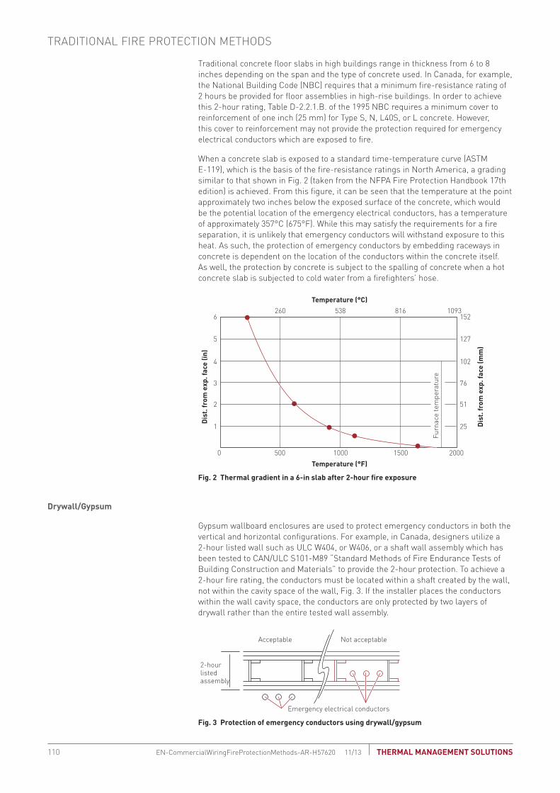
Traditional concrete floor slabs in high buildings range in thickness from 6 to 8 inches depending on the span and the type of concrete used. In Canada, for example, the National Building Code (NBC) requires that a minimum fire-resistance rating of 2 hours be provided for floor assemblies in high-rise buildings. In order to achieve this 2-hour rating, Table D-2.2.1.B. of the 1995 NBC requires a minimum cover to reinforcement of one inch (25 mm) for Type S, N, L40S, or L concrete. However, this cover to reinforcement may not provide the protection required for emergency electrical conductors which are exposed to fire.
When a concrete slab is exposed to a standard time-temperature curve (ASTM E-119), which is the basis of the fire-resistance ratings in North America, a grading similar to that shown in Fig. 2 (taken from the NFPA Fire Protection Handbook 17th edition) is achieved. From this figure, it can be seen that the temperature at the point approximately two inches below the exposed surface of the concrete, which would be the potential location of the emergency electrical conductors, has a temperature of approximately 357°C (675°F). While this may satisfy the requirements for a fire separation, it is unlikely that emergency conductors will withstand exposure to this heat. As such, the protection of emergency conductors by embedding raceways in concrete is dependent on the location of the conductors within the concrete itself. As well, the protection by concrete is subject to the spalling of concrete when a hot concrete slab is subjected to cold water from a firefighters’ hose.
Temperature (°C)
Temperature (°F)
2606
5
4
3
2
1
152
127
102
76
51
25 Dis
t. fr
om e
xp. f
ace
(mm
)
Dis
t. fr
om e
xp. f
ace
(in)
Furn
ace
tem
pera
ture
0 500 1000 1500 2000
538 816 1093
Fig. 2 thermal gradient in a 6-in slab after 2-hour fire exposure
drywall/Gypsum
Gypsum wallboard enclosures are used to protect emergency conductors in both the vertical and horizontal configurations. For example, in Canada, designers utilize a 2-hour listed wall such as ULC W404, or W406, or a shaft wall assembly which has been tested to CAN/ULC S101-M89 “Standard Methods of Fire Endurance Tests of Building Construction and Materials” to provide the 2-hour protection. To achieve a 2-hour fire rating, the conductors must be located within a shaft created by the wall, not within the cavity space of the wall, Fig. 3. If the installer places the conductors within the wall cavity space, the conductors are only protected by two layers of drywall rather than the entire tested wall assembly.
Emergency electrical conductors
2-hourlistedassembly
Acceptable Not acceptable
Fig. 3 Protection of emergency conductors using drywall/gypsum
TRADITIONAL FIRE PROTECTION METHODS
THERMAL MANAGEMENT SOLUTIONSEN-CommercialWiringFireProtectionMethods-AR-H57620 11/13110
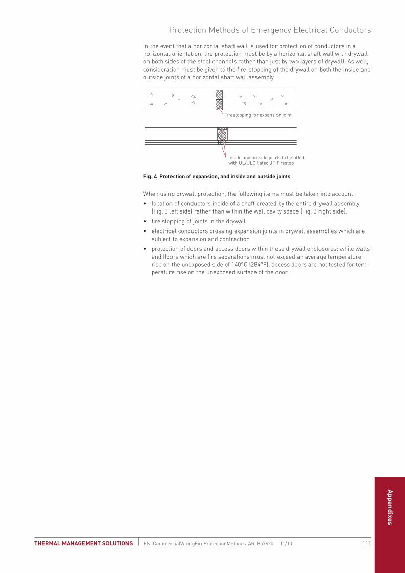
Fire-Rated Cables
Space Saving Cable System
Service Entrance Cable System
sCodes and Standards
Technical Data Sheets
Appendixes
In the event that a horizontal shaft wall is used for protection of conductors in a horizontal orientation, the protection must be by a horizontal shaft wall with drywall on both sides of the steel channels rather than just by two layers of drywall. As well, consideration must be given to the fire-stopping of the drywall on both the inside and outside joints of a horizontal shaft wall assembly.
Inside and outside joints to be filledwith UL/ULC listed JF Firestop
Firestopping for expansion joint
Fig. 4 Protection of expansion, and inside and outside joints
When using drywall protection, the following items must be taken into account:
• location of conductors inside of a shaft created by the entire drywall assembly (Fig. 3 left side) rather than within the wall cavity space (Fig. 3 right side).
• fire stopping of joints in the drywall
• electrical conductors crossing expansion joints in drywall assemblies which are subject to expansion and contraction
• protection of doors and access doors within these drywall enclosures; while walls and floors which are fire separations must not exceed an average temperature rise on the unexposed side of 140°C (284°F), access doors are not tested for tem-perature rise on the unexposed surface of the door
Protection Methods of Emergency Electrical Conductors
111 THERMAL MANAGEMENT SOLUTIONS EN-CommercialWiringFireProtectionMethods-AR-H57620 11/13

Concrete block
When concrete block is used for protection of emergency conductors, it must be ensured that the conductors are located within a vertical service space created by the concrete block rather than within the block cavity itself, Fig. 5. If the conductors are located within the block cavity, the fire-resistance rating provided by half of the block will not provide the minimum protection required by the NBC (Canada).
<2-hour fireresistance
rating2-hourconcreteblock
Emergency electrical conductors
Acceptable Unacceptable
Fig. 5 Protection of emergency conductors using concrete block
UL/ULC Fire-Rated Mineral Insulated Cable
This cable is manufactured using only inorganic materials, copper and magnesium oxide. It does not burn, contribute fuel, or produce smoke when exposed to fire conditions. MI cable may be directly mounted, using clips and straps available from Pentair Thermal Management, on noncombustible surfaces such as concrete or masonry, or supported by steel rod and channel (trapeze) systems. The cable, clips, and straps have been subjected to the 2-hour fire test. In this test, the cables are required to maintain the voltage for the listed time. No additional protection is required for this cable, Fig. 6.
Steelrod
1-1/2" channel(to maintain NEC/CEC
free air rating)Multiconductor
cable
Free air-ratedinstallation
Free air-rated installation
Surface-mounted installation
Singleconductor
cables Steelchannel
Noncombustiblematerial
Noncombustiblematerial
Singleconductorcables
Fig. 6 MI cable installed on noncombustible surface
TRADITIONAL FIRE PROTECTION METHODS
THERMAL MANAGEMENT SOLUTIONSEN-CommercialWiringFireProtectionMethods-AR-H57620 11/13112

Fire-Rated Cables
Space Saving Cable System
Service Entrance Cable System
sCodes and Standards
Technical Data Sheets
Appendixes
The following tables present sheath resistance data for Pyrotenax System 1850 MI cables. Resistance values are given in ohms per thousand feet at 25°C (77°F). The last column in each table lists the equivalent grounding conductor size based on the sheath resistance.
Both the Canadian Electrical Code (Rule 10-804) and the National Electrical Code (Section 250.118(9) and Section 332.108) allow the sheath of copper sheathed mineral insulated cables to be employed as an equipment grounding conductor.
tAbLe 1 sInGLe CondUCtoR CAbLe
Cable referenceConductor size (AwG/kcmil)
nominal sheath resistance (ohms per 1000 ft)
equivalent grounding conductor size (AwG)
1/14-230 14 0.706 10
1/12-246 12 0.618 8
1/10-277 10 0.562 8
1/8-298 8 0.438 8
1/6-340 6 0.355 6
1/4-402 4 0.222 4
1/3-449 3 0.179 3
1/2-449 2 0.171 3
1/1-496 1 0.147 2
1/1/0-512 1/0 0.149 2
1/2/0-580 2/0 0.117 1
1/3/0-621 3/0 0.093 1/0
1/4/0-684 4/0 0.103 1/0
1/250-746 250 0.087 1/0
1/350-834 350 0.102 1/0
1/500-1000 500 0.073 2/0
113 THERMAL MANAGEMENT SOLUTIONS EN-PyrotenaxMIsheathbonding-AR-H57621 11/13
PYROTENAX MI SHEATH BONDING AND GROUNDING

tAbLe 2 two CondUCtoR CAbLe
Cable referenceConductor size (AwG)
nominal sheath resistance (ohms per 1000 ft)
equivalent grounding conductor size (AwG)
2/14-371 14 0.327 6
2/12-402 12 0.247 4
2/10-449 10 0.242 4
2/8-512 8 0.188 3
2/6-590 6 0.142 2
2/4-684 4 0.116 1
2/3-768 3 0.092 1/0
2/2-865 2 0.071 2/0
2/1-975 1 0.057 3/0
tAbLe 3 tHRee CondUCtoR CAbLe
Cable referenceConductor size (AwG)
nominal sheath resistance (ohms per 1000 ft)
equivalent grounding conductor size (AwG)
3/14-387 14 0.231 4
3/12-480 12 0.140 2
3/10-480 10 0.140 2
3/8-590 8 0.104 1/0
3/6-621 6 0.102 1/0
3/4-746 4 0.071 2/0
3/3-834 3 0.057 3/0
tAbLe 4 FoUR CondUCtoR CAbLe
Cable referenceConductor size (AwG)
nominal sheath resistance (ohms per 1000 ft)
equivalent grounding conductor size (AwG)
4/14-465 14 0.155 2
4/12-465 12 0.217 4
4/10-590 10 0.117 1
4/8-590 8 0.117 1
4/6-730 6 0.075 2/0
tAbLe 5 seVen CondUCtoR CAbLe
Cable referenceConductor size (AwG)
nominal sheath resistance (ohms per 1000 ft)
equivalent grounding conductor size (AwG)
7/14-496 14 0.168 2
7/12-543 12 0.123 1
7/10-621 10 0.102 1/0
7/8-710 8 0.075 2/0
PYROTENAX MI SHEATH BONDING AND GROUNDING
THERMAL MANAGEMENT SOLUTIONSEN-PyrotenaxMIsheathbonding-AR-H57621 11/13114

Fire-Rated Cables
Space Saving Cable System
Service Entrance Cable System
sCodes and Standards
Technical Data Sheets
Appendixes
MoIstURe PenetRAtIon
Magnesium oxide is hygroscopic, resulting in the uptake and retention of moisture under certain humidity and temperature conditions. When MI cable is not properly sealed and is subjected to these conditions, moisture penetrates several inches into the insulation, thereby reducing the insulation resistance. Pentair Thermal Management’s tests confirm that the moisture will not penetrate further into the cable and can be removed by applying heat to the cable to force the moisture out the open end. The insulation resistance will be restored once the cable has been dried and sealed.
dIeLeCtRIC stRenGtH
Although the dielectric strength of magnesium oxide insulation decreases with temperature, because of the way MI cables are constructed this decrease has no detrimental effect on cable functionality.
30
20
40
50
60
70
80
90
(1000°C)1832°F
(900°C)1652°F
(800°C)1472°F
(700°C)1292°F
(600°C)1112°F
Temperature
Volt
s pe
r M
IL o
f ins
ulat
ion
(500°C)932°F
(400°C)752°F
Graph 1 dielectric strength of MI cable as a function of temperature
115 THERMAL MANAGEMENT SOLUTIONS EN-CommercialWiringMagnesiumOxideInsulation-AR-H57622 11/13
MAGNESIUM OXIDE INSULATION CHARACTERISTICS

InsULAtIon ResIstAnCe
The insulation resistance of magnesium oxide decreases with increasing temperatures as shown. This decrease is unimportant at temperatures up to 250°C (482°F), the maximum continuous operating temperature of MI cable.
0.01
0.001
0.1
1.0
10.0
10,000
1,000
100,000
100.0
(700°C)1292°F
(600°C)1112°F
(500°C)932°F
(400°C)752°F
(300°C)572°F
Insu
lati
on r
esis
tanc
e (M
-Ohm
s ¥
1000
ft)
(200°C)392°F
(100°C)212°F
Temperature
Graph 2 Insulation resistance of MI cable as a function of temperature
tHeRMAL CondUCtIVIty
Unlike most electrical insulations, magnesium oxide has a relatively high thermal conductivity. This enables the heat to be quickly conducted from the outside sheath and dissipated to the -surrounding air. This conductivity increases when magnesium oxide is compacted. The -manufacturing process produces a specific weight of approximately 2.2 and a thermal conductivity of 16.4 BTU/°F/sq ft/in/hr.
20
12
8
6
16
18
10
14
1.4 1.6 1.8 2.0 2.2Specific weight
Ther
mal
con
duct
ivity
(BTU
/F/S
q ft
/in/
hr)
Graph 3 thermal conductivity of magnesium oxide at different levels of compaction
MAGNESIUM OXIDE INSULATION CHARACTERISTICS
THERMAL MANAGEMENT SOLUTIONSEN-CommercialWiringMagnesiumOxideInsulation-AR-H57622 11/13116

Fire-Rated Cables
Space Saving Cable System
Service Entrance Cable System
sCodes and Standards
Technical Data Sheets
Appendixes
PoweR FACtoR
The power factor of magnesium oxide insulation is very low compared to that of most electrical cable insulations. When measured at room temperature, 60 Hz and 40 volts per mil, it is approximately 0.1%. This value increases with temperature to approximately 1.0% at 250°C (482°F).
dIeLeCtRIC ConstAnt
The dielectric constant is approximately 4 over a range from 60 Hz to 400 MHz and is relatively constant up to 300°C (572°F).
Power Factor
117 THERMAL MANAGEMENT SOLUTIONS EN-CommercialWiringMagnesiumOxideInsulation-AR-H57622 11/13

MAGNESIUM OXIDE INSULATION CHARACTERISTICS
THERMAL MANAGEMENT SOLUTIONSEN-CommercialWiringMagnesiumOxideInsulation-AR-H57622 11/13118


CommerCiaL fire-rated WiringsystemsTHERMAL MANAGEMENT SOLUTIONS WWW.PENTAIRTHERMAL.COMEN-CommercialFireRatedSpecialtyWiringCatalog-SB-H57513 11/13THERMAL MANAGEMENT SOLUTIONS
NORTH AMERICA Tel: +1.800.545.6258Fax: +1.800.527.5703Tel: +1.650.216.1526Fax: [email protected]
EuROpE, MIddlE EAsT, AfRICATel: +32.16.213.511Fax: [email protected]
AsIA pACIfICTel: +86.21.2412.1688Fax: [email protected]
lATIN AMERICATel: +1.713.868.4800Fax: [email protected]
Pentair, DigiTrace, Handvise, Pyropak, PyroSizer, Pyrotenax, QuickTerm, Sheathmaster, System 1850, and System 1850-SE are owned by Pentair or its global affiliates. All other trademarks are the property of their respective owners. Pentair reserves the right to change specifications without prior notice.
© 2004-2013 Pentair.
WWW.pENTAIRTHERMAl.COM
NO
RTH
AMER
ICA 2013com
mercial Fire-rated W
iring systems