Embed Size (px)
Citation preview
1
Sole Manufacturer and Distributor in the Czech Republic: ATEC v.o.s.
Location of factory: ATEC v.o.s., Opolanská 350, 289 07 Libice nad Cidlinou Czech Republic
ATEC 212 SOLO ROTAX 582 UL DCDI 2V
Flight and Operations Manual
Libice nad Cidlinou January 2007
2
Type of aeroplane ATEC 212 SOLO Serial number …………………………………………………… Identification label …………………………………………………… LAA CR type licence …………………… issued ……………………
This aircraft is not registered at the state office and is to be operated at operator’s own responsibility
The aeroplane must be operated according to the information and limits of this flight manual. This manual must ever be on the board of aeroplane
This manual must at all times be carried on board of the aircraft
3
Contents Chapter General ……………………………………. 1 Operational Limits …………………………… 2 Emergency Instructions ……………………… 3 Standard Procedures ……………………… 4 Specifications …………………………… 5 Assembly, Disassembly ……………………… 6 Description of Aircraft and its Systems …… 7 Maintenance …………………………… 8 Weight, Centre of Gravity ………………….. 9

4
Chapter 1 1. General 1.1. Introduction 1.2. Personal Data of the Owner 1.3. Description of the Aeroplane 1.4. Completing of the Manual, Changes 1.5. Specification 1.6. Three-View Sketch
5
1.1. Introduction The information provided by this manual is necessary for an effective and save operation of the ATEC 212 SOLO aircraft. Also included are information and documents of importance from the manufacturer. 1.2. Personal data of the owner Owner of aircraft: Address: Telephone No: Date from to: Owner of aircraft: Address: Telephone No: Date from to: Owner of aircraft: Address: Telephone No: Date from to:
6
1.3. Description of the Aeroplane ATEC 212 SOLO is an ultralight single-seater cantilever low-wing aircraft of an all carbon composite construction. It is equipped with a tail landing gear with the steerable tail wheel. The power plant is a pull arrangement and consists of a ROTAX 582 UL DCDI 2V 65 HP engine and a two-blade or three-blade ground adjustable propeller FITI. 1.4. Specification Dimensions Wing span ……………………………………. 7,48 m Length of fuselage ……………………………. 5,2 m Total height ……………………………………. 1,4 m Wing area ……………………………………. 7,27 m2
Depth of mean aerodynamic chord …………….. 1,032 m Span of horizontal tail surface …………….. 2,18 m Flap position ……………………………………. I 10° II 20° III 35° Airfoil Section Root section …………………………………….. SM 701 End section …………………………………….. SM 701 Tail Wheel Landing Gear Wheel spacing…………………………………….. 1,56 m Wheel base …………………………………….. 3,66 m Tyre dimensions …………………………….. 350 * 120 Tyre pressure …………………………………….. 0,12 MPa / 1,2 atp Springing system Main wheels …………………………….. composite spring Tail wheel …………………………….. composite spring Brakes ……………………………………. Main wheels hydraulic disc brakes Rescue System installed / not installed………. Weights Empty weight …………………………………….. kg Maximum take-off weight …………………….. 300 315 kg
7
Driving Unit Propeller manufacturer ………………... Josef Faturik Type of propeller ……………… FITI ECO COMPETITION 2 blade, 3-blade Engine manufacturer …………………… Bombardier – ROTAX GmbH Type of engine …………………… ROTAX 582 UL DCDI 2V 65 HP Power Take-off power …………………… 48 kW / 65 HP / 6500 RPM Maximum continuous power …………… RPM Cruising power …………………… RPM Engine Speed Maximum take-off engine speed ….… 6800 RPM / 5 minutes maximum Max. continuous engine speed ……. 6500 RPM Cruising engine speed ……. 5000 RPM Idling ……. 2000 RPM approximately Engine Cylinders Temperature Maximum ……………………………. 150°C Operational ……………………………. 110 - 130°C Cooling Liquid Temperature Maximum ……………………………. 80°C Minimum ……………………………. 65°C Fuel Pressure Maximum ……………………………. 0,4 bar Minimum ……………………………. 0,2 bar Operational Temperature Maximum ……………………………. 50°C Minimum ……………………………. -25°C Fuel Type ……………………………. See Art. 2.9. Oil Type 1. Engine lubrication, rotary slide valve lubrication – motor oil for high loaded two stroke
engines of API-TC class (CASTROL TTS equivalent). Oil / Fuel mixture 1: 50 (2%). 2. Gearbox lubrication – gearboxes oil of API-GL5 or API-GL6, SAE 140 EP or 85W – 140
EP.
ROTAX 582 UL DCDI 2V is not certificate as an aircraft engine and a failure may occur whenever. The pilot is fully responsible for consequence of engine failure

8
1.6. Three-View Sketch
9
Chapter 2 2. Operational Limits 2.1. Introduction 2.2. Air Speeds 2.3. Weights 2.4. Centre of Gravity 2.5. Manoeuvre and Gust Envelope 2.6. Permitted Manoeuvres 2.7. Operational Load Factors 2.8. Type of Operation 2.9. Crew 2.10. Fuel 2.11. Wind 2.12. Other Limits 2.13. Placards and Markings
10
2.1. Introduction The chapter 2 contents are operational limits necessary for a save operation of the aircraft 2.2. Air Speeds Never exceed speed vNE … 286 km/h 154 kt
Do not exceed this speed in any case
Design manoeuvre speed vA … 187 km/h 101 kt
Do not use full deflection of the rudders and sudden control operations. Overload of the aircraft may occur
Maximum design cruising speed vC … 222 km/h 120 kt
Operation over this speed must be conducted with caution in smooth air only
Maximum cruising speed at severe turbulence vRA … 200 km/h 108 kt
Never exceed this speed at severe turbulence
Maximum speed at flaps deflection 10° vFI …… 140 km/h ….. 75 kt Maximum speed at flaps deflection 20° vFII ....... 130 km/h ...... 70 kt Maximum speed at full deflection 35° vFE …… 120 km/h ….. 65 kt Maximum recommended speed at def. 35° vFIII …… 100 km/h ….. 55 kt
Do not exceed this speed by flaps deflected
Stalling speed flaps retracted vS1 …… 76,4 km/h ….. 41 kt
The loss of uplift and fall of aircraft with flaps retracted happens by this speed
Stalling speed in landing configuration vSO …... 64,2 km/h ….. 35 kt
The loss of uplift and fall of aircraft with flaps position III deflected happens by this speed
11
2.3. Weights Empty weight …………………………………. kg Maximum take-off weight …………………. 300 315 kg Useful load …………………………………. kg
Never exceed the maximum take-off weight of the aeroplane!
2.4. Centre of Gravity ( CG ) CG of the empty aeroplane ………………… % MAC
Flight range of CG ………………………… 28 – 36% MAC
12
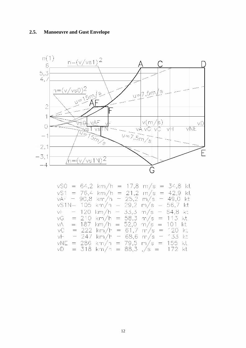
2.5. Manoeuvre and Gust Envelope
13
2.6. Permitted Manoeuvres Category of the aeroplane: Normal Except of the normal flight manoeuvres, the sharp turns up to bank of 60o, level and climbing turns are permitted.
Acrobatics, intended spins and stalls are prohibited
2.7. Operational Load Factors Maximum positive load factor in CG ……… +6,0 g Maximum negative load factor in CG ……… -4,0 g 2.8. Type of operation Permitted day flights VFR only ( flights by unobstructed field of vision )
IFR flights ( instrument flights ) and flights by ice formation are prohibited
2.9. Crew Number of seats …………………. 1 Minimum weight of crew …………. 65 kg see Art. 9.4. Maximum weight of crew …………. 90 kg see Art. 9.4. 2.10. Fuel Recommended motor unleaded petrol of minimum octane number RON 95 with oil. Oil / Fuel mixture 1 : 50. Fuel capacity …………………. 49 l Not usable rest of fuel …………. 0,7 l

14
2.11. Wind The safe taking off and landing is possible if the following wind speed limits are not exceeded: a) taking off or landing against wind ………. up to 12 m/s b) taking off or landing tail wind ………. up to 3 m/s c) taking off or landing cross wind ………. up to 3 m/s 2.12. Other limits Smoking and using of mobile telephones is prohibited in the aircraft. Transportation of explosives and free loaded objects is prohibited. 2.13. Placards and Markings The aircraft shall be equipped with mandatory placards placed on instrument panel containing following information: - Identification of aircraft
Identification label. Serial number. Designation. Empty weight. Maximum take off weight.
- Operating limitations
Weight limits depending on weight of crew, fuel and luggage. Speed limits for standard flight configurations.
- Passenger warnings
Definition of aircraft category, its airworthiness conditions and limitations. Intentional spins, stalls and aerobatics prohibition.

15
Chapter 3 3. Emergency Instructions 3.1. Engine Failure Taking-Off 3.2. Engine Failure in Flight 3.3. Rescue System Application 3.4. Fire in Flight 3.5. Power-Off Flight 3.6. Emergency Landing 3.7. Safety Landing 3.8. Aborted landing 3.9. Vibration
16
3.1. Engine Failure on Take-Off 1. Push stick forward aircraft into gliding attitude and maintain airspeed of 100
km/h (54 kt). 2. Determine the wind direction, adjust flaps for suitable position, turn off fuel valve,
switch-off ignition, adjust safety belts and switch-off the master switch just before landing.
A. At a height up to 50 m get the aircraft into landing configuration and carry out a landing with respect for obstructions in take-off direction.
B. At a height above 50 m choose a suitable area for emergency landing. 3.2. Engine Failure in Flight 1. Get the aircraft into gliding attitude and maintain airspeed of 100 km/h (54 kt). 2. Check a fuel level, switch on and make sure ignition is switched on. 3. If no problem found, try restarting the engine once more using additional fuel system. 4. If restarting impossible, use the instructions 3.1. 3.3. Rescue system deployment In distress by final loss of flight control do activate the rescue system 1. Switch off ignition 2. Adjust safety belts 3. Activate the rescue system In case of landing on a limited area when collision is inevitable, use the rescue system for a braking devise.
The aircraft can be damaged or the crew may be injured due to using a rescue system
3.4. Fire in flight 1. Close the fuel valve 2. Open the throttle 3. Switch off the main switch and ignition 4. Do emergency landing 5. Get off the aircraft 3.5. Power-off flight 1. Speed …………………… 100 km/h ….. 54 kt 3. Flaps retracted 4. Normal flight conditions

17
3.6. Emergency landing 1. Carried out in case of engine failure 2. Speed ……………………. 100 km/h ….. 54 kt 3. Adjust safety belts 4. Flaps according to situation 5. Announce the situation by the aeroplane radio station 6. Close the fuel valve 7. Turn off ignition 8. Turn off the main switch
In case of emergency landing onto a terrain and surfaces non-approved for light aircraft landings an aircraft damage and crew injury may occur
3.7. Precautionary landing Carry out in case of the loss of orientation, fuel exhaustion or for other reason if the aircraft is fully controllable. 1. Determine the wind direction 2. Choose a suitable landing area 3. Carry out a low pass into the wind along the right-hand side of landing area and
inspect the area thoroughly. 4. Carry out a circuit flight 5. Calculate the landing plan 6. Land in the first third of the landing area using landing flaps 3.8. Aborted landing Carry out in case of wrong calculation of landing manoeuvre or after jump out by landing in case of pilot’s consideration to abort landing manoeuvre and continue to fly. 1. Set up engine speed on maximum power 2. Set up take-off flaps position – I 3. Get level speed 110 km/h ….. 59 kt 4. Draw up control stick slowly to get aircraft into climbing at speed 140 km/h ..... 75 kt 5. Retract flaps at an air speed 120 km/h ….. 76 kt 6. Keep runway direction all the take off time using rudder 3.9. Vibrations In case of unusual vibrations occurs. 1. Set the engine speed to where vibration is least 2. Carry out the safety landing checks for a possible emergency landing and head for the
nearest airport

18
Chapter 4 4. Standard Procedures 4.1 Pre-Flight Inspection 4.1.1 Procedures Before Entering the Cockpit 4.1.2 Procedures After Entering the Cockpit 4.2 Procedures Before Starting the Engine and
Starting the Engine 4.3 Warming up the Engine, Engine Check 4.4 Taxiing 4.5 Pre Take-Off 4.6 Take-Off and Climb Away 4.7 Cruising Flight 4.8 Descend and Landing 4.9 Flight in the Rain

19
4.1. Pre-Flight Inspection It is important to carry out a proper pre-flight inspection failure to do so or perform an incomplete inspection could be the cause of an accident. The manufacturer recommends using the following procedure: 4.1.1. Procedures Before Entering the Cockpit 1. Check ignition - turned off. 2. Check main switch – turned off 3. Check the wings, wing surfaces ailerons and flaps, clearances, hinges and connections
of the controls, security of the wing pins, Pitot tube. 4. Check the tail surfaces, elevator and rudder for secure connections, clearances and free
movement. 5. Check the fuselage, the surface and state. 6. Check the landing gear, laminate springs, security of main and front wheels, their
covers, screws and nuts, proper tire pressure, break function. 7. Engine – the state of fastening of the engine covers, the state of the engine bed, intact
fuel, oil and cooling system hoses, the fuel system drain. 8. Propeller – the surface state, if it is intact, the state and fastening of the propeller cone. 9. Canopy – control of fastening and proper locking of the canopy, correct functioning
and condition of the electrical installation of instruments, the state of the flight instruments, control of the fuel level, proper functioning of controls.
Before entering the cockpit step on the marked foot-path on the wing only. Stepping outside the marked area especially on the flap may damage the airframe seriously
4.1.2 Procedures After Entering the Cockpit 1. Check foot-operated controls 2. Check brakes – brakes on 3. Check hand - operated controls 4. Check flaps 5. Check engine controls 6. Check fuel valve 7. Check fuel level indicator 8. Check main switch – turned off 9. Check ignition – turned off 10. Check instruments – state, zero positions, adjust altimeter
20
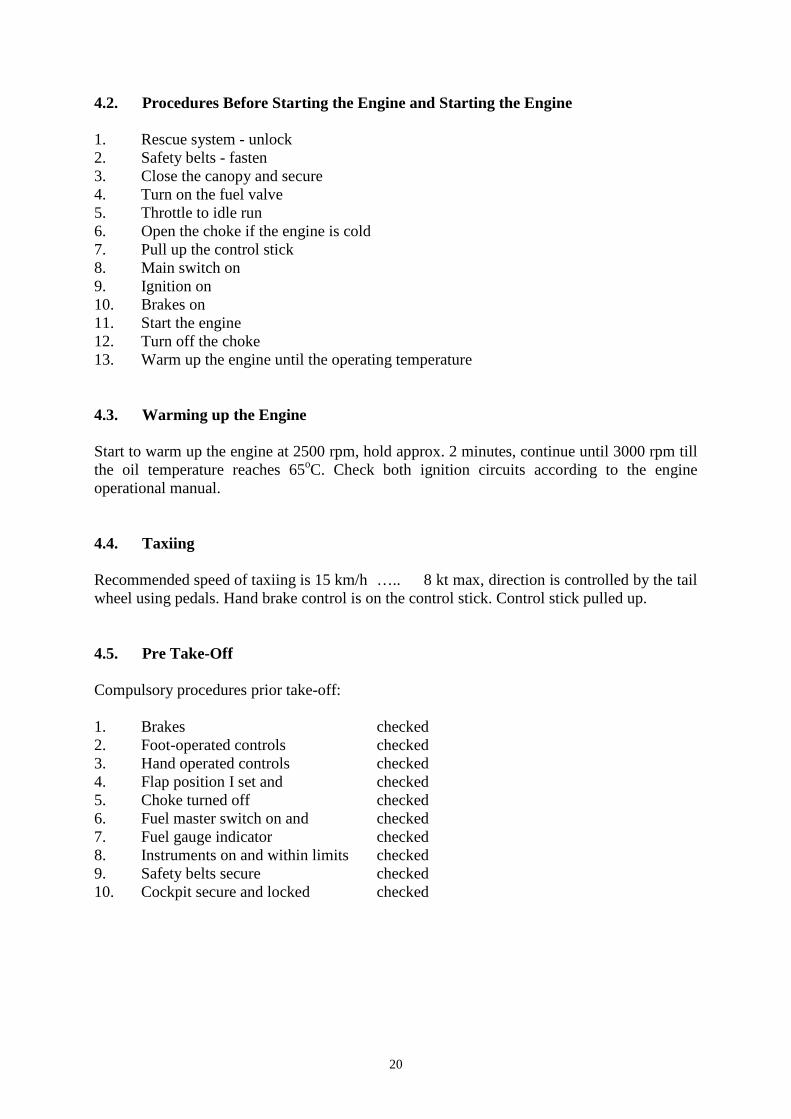
4.2. Procedures Before Starting the Engine and Starting the Engine 1. Rescue system - unlock 2. Safety belts - fasten 3. Close the canopy and secure 4. Turn on the fuel valve 5. Throttle to idle run 6. Open the choke if the engine is cold 7. Pull up the control stick 8. Main switch on 9. Ignition on 10. Brakes on 11. Start the engine 12. Turn off the choke 13. Warm up the engine until the operating temperature 4.3. Warming up the Engine Start to warm up the engine at 2500 rpm, hold approx. 2 minutes, continue until 3000 rpm till the oil temperature reaches 65oC. Check both ignition circuits according to the engine operational manual. 4.4. Taxiing Recommended speed of taxiing is 15 km/h ….. 8 kt max, direction is controlled by the tail wheel using pedals. Hand brake control is on the control stick. Control stick pulled up. 4.5. Pre Take-Off Compulsory procedures prior take-off: 1. Brakes checked 2. Foot-operated controls checked 3. Hand operated controls checked 4. Flap position I set and checked 5. Choke turned off checked 6. Fuel master switch on and checked 7. Fuel gauge indicator checked 8. Instruments on and within limits checked 9. Safety belts secure checked 10. Cockpit secure and locked checked
21
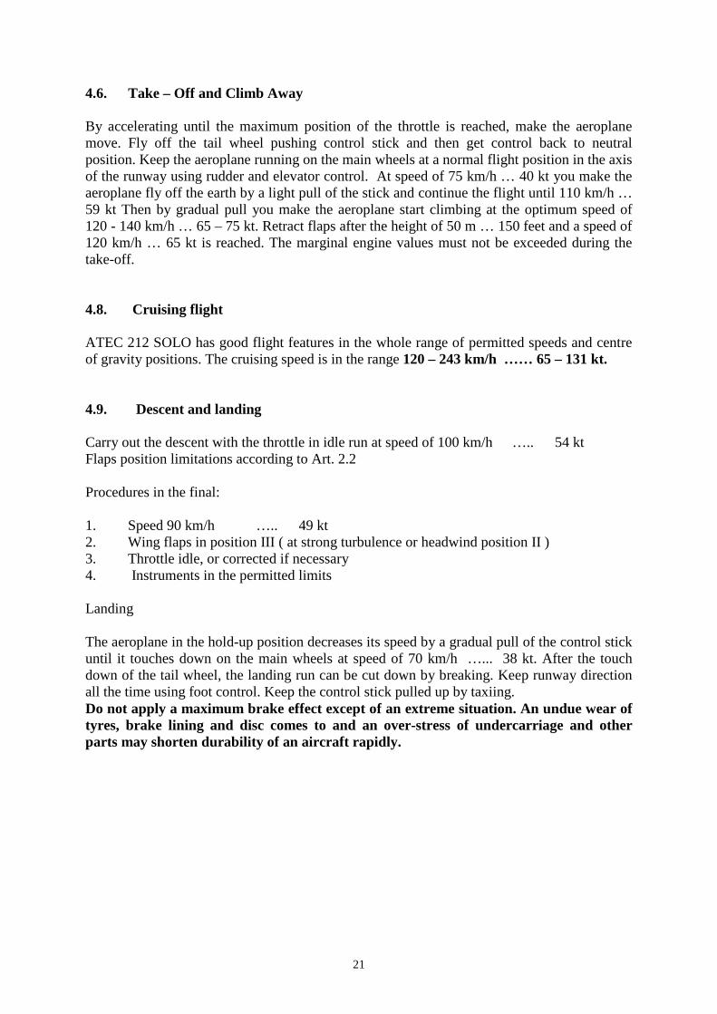
4.6. Take – Off and Climb Away By accelerating until the maximum position of the throttle is reached, make the aeroplane move. Fly off the tail wheel pushing control stick and then get control back to neutral position. Keep the aeroplane running on the main wheels at a normal flight position in the axis of the runway using rudder and elevator control. At speed of 75 km/h … 40 kt you make the aeroplane fly off the earth by a light pull of the stick and continue the flight until 110 km/h … 59 kt Then by gradual pull you make the aeroplane start climbing at the optimum speed of 120 - 140 km/h … 65 – 75 kt. Retract flaps after the height of 50 m … 150 feet and a speed of 120 km/h … 65 kt is reached. The marginal engine values must not be exceeded during the take-off. 4.8. Cruising flight ATEC 212 SOLO has good flight features in the whole range of permitted speeds and centre of gravity positions. The cruising speed is in the range 120 – 243 km/h …… 65 – 131 kt. 4.9. Descent and landing Carry out the descent with the throttle in idle run at speed of 100 km/h ….. 54 kt Flaps position limitations according to Art. 2.2 Procedures in the final: 1. Speed 90 km/h ….. 49 kt 2. Wing flaps in position III ( at strong turbulence or headwind position II ) 3. Throttle idle, or corrected if necessary 4. Instruments in the permitted limits Landing The aeroplane in the hold-up position decreases its speed by a gradual pull of the control stick until it touches down on the main wheels at speed of 70 km/h …... 38 kt. After the touch down of the tail wheel, the landing run can be cut down by breaking. Keep runway direction all the time using foot control. Keep the control stick pulled up by taxiing. Do not apply a maximum brake effect except of an extreme situation. An undue wear of tyres, brake lining and disc comes to and an over-stress of undercarriage and other parts may shorten durability of an aircraft rapidly .

22
4.10. Flight in the rain During the flight in the rain, the pilotage should be carried out with increased caution because of the decreased visibility and cockpit transparency. Furthermore, one should take into account a shortened hold-up position during the landing and extended take-off distance. Maintain the following speeds during the flight in the rain: 1. Climb away 140 km/h ….. 75 kt 2. Cruising flight 120 – 200 km/h … 65 – 108 kt 3. Descent at landing 100 km/h ….. 54 kt, flaps I or II, see Art. 2.2

23
Chapter 5 5. Performances 5.1. Introduction 5.2. Stalling Speeds 5.3. Take off Distance at 15 m / 50 ft Height 5.4. Rate of Climb 5.5. Cruising Speeds 5.6. Range of Flight
24
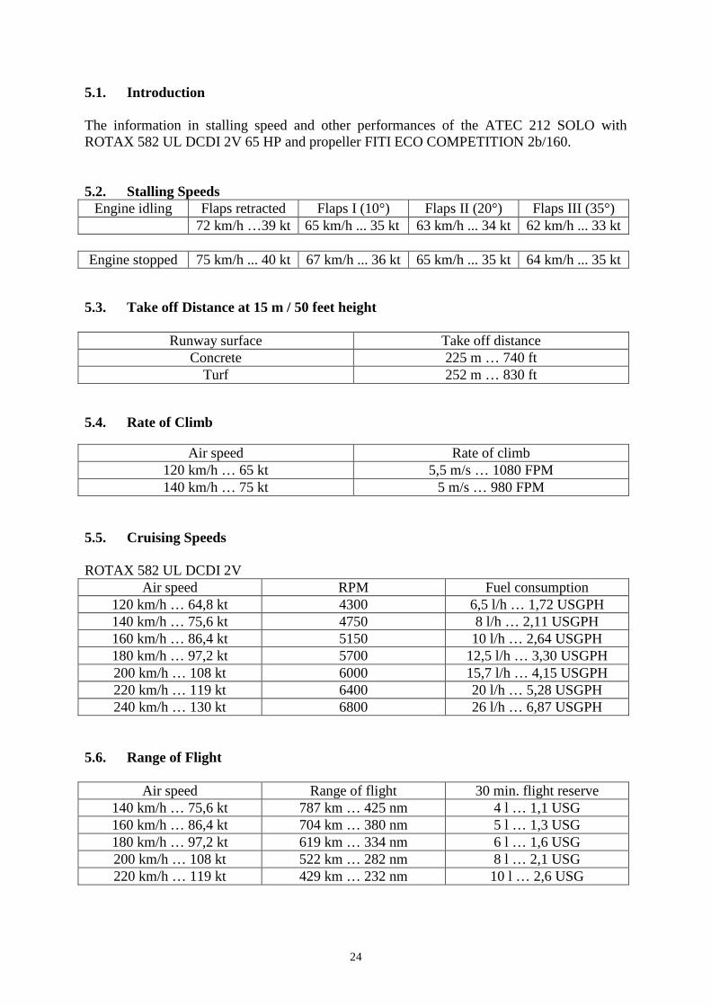
5.1. Introduction The information in stalling speed and other performances of the ATEC 212 SOLO with ROTAX 582 UL DCDI 2V 65 HP and propeller FITI ECO COMPETITION 2b/160. 5.2. Stalling Speeds
Engine idling Flaps retracted Flaps I (10°) Flaps II (20°) Flaps III (35°) 72 km/h …39 kt 65 km/h ... 35 kt 63 km/h ... 34 kt 62 km/h ... 33 kt Engine stopped 75 km/h ... 40 kt 67 km/h ... 36 kt 65 km/h ... 35 kt 64 km/h ... 35 kt
5.3. Take off Distance at 15 m / 50 feet height
Runway surface Take off distance Concrete 225 m … 740 ft
Turf 252 m … 830 ft 5.4. Rate of Climb
Air speed Rate of climb 120 km/h … 65 kt 5,5 m/s … 1080 FPM 140 km/h … 75 kt 5 m/s … 980 FPM
5.5. Cruising Speeds ROTAX 582 UL DCDI 2V
Air speed RPM Fuel consumption 120 km/h … 64,8 kt 4300 6,5 l/h … 1,72 USGPH 140 km/h … 75,6 kt 4750 8 l/h … 2,11 USGPH 160 km/h … 86,4 kt 5150 10 l/h … 2,64 USGPH 180 km/h … 97,2 kt 5700 12,5 l/h … 3,30 USGPH 200 km/h … 108 kt 6000 15,7 l/h … 4,15 USGPH 220 km/h … 119 kt 6400 20 l/h … 5,28 USGPH 240 km/h … 130 kt 6800 26 l/h … 6,87 USGPH
5.6. Range of Flight
Air speed Range of flight 30 min. flight reserve 140 km/h … 75,6 kt 787 km … 425 nm 4 l … 1,1 USG 160 km/h … 86,4 kt 704 km … 380 nm 5 l … 1,3 USG 180 km/h … 97,2 kt 619 km … 334 nm 6 l … 1,6 USG 200 km/h … 108 kt 522 km … 282 nm 8 l … 2,1 USG 220 km/h … 119 kt 429 km … 232 nm 10 l … 2,6 USG

25
Chapter 6 6. Assembly and Dismantling 6.1. Introduction 6.2. Dismantling the Horizontal Tail Surface and the
Rudder 6.3. Dismantling the Wings 6.4. Assembly

26
6.1. Introduction The assembly of individual parts of the aeroplane is described in this chapter. At least two persons are necessary for the assembly and dismantling. 6.2. Dismantling the Horizontal and Vertical Rudder The HT and VT stabilizers are an integral part of the fuselage Dismantling VT rudder. Disconnect control. Release and unbolt the bolt M6 at the lower part of the rudder. Take out the rudder from the hinges moving it down and backwards. Dismantling elevator. Release and remove elevator pins using suitable tongs. Take out elevator moving it backwards. 6.3. Dismantling the wings Disconnect the pins of ailerons and flap control in the cabin space. Release and remove the lock nut of the M10 bolt of the wing pins. Screw the bolt off by about 20 mm. The helper lifts the wing a bit by holding it at the end. By light taps on the head of the bolt the bottom pin is knocked-out. Unscrew the bolt and remove the pin. Then the upper pin is driven out with the help of a rod with 18 mm diameter. After removed pins lift up the wing and disconnect the hoses of the static and total pressure. Those hoses must not be interchanged during assembly. Disconnect strobe-light or position light cables if the aircraft is equipped with them. 6.4. Assembly The assembly is carried out in the opposite way. All pins must be cleaned and greased and then secured. Take care about the proper adjustment of ailerons, which is done by shortening and extending the aileron connection struts. Ever use new securing wire, new split pins and new self-locking nuts.
27
Chapter 7 7. Description of the Aeroplane and Its Systems 7.1. Wing 7.2. Fuselage 7.3. Tail Surfaces 7.4. The Landing Gear 7.5. Control 7.6. The Driving Unit 7.7. Fuel System 7.8. Instrument Equipment 7.9. The Sense of Motion of the Control Elements

28
7.1. Wing The cantilever tapered wing with conventional ailerons, slotted flaps and wing-tips. The main spar of laminated beech wood is in the 30% depth of wing. The wing skin is made of carbon sandwich. The wing is reinforced by ribs of plastic and composites, the root ribs are of carbon – nomex honeycomb sandwich. Ailerons and flaps are of all composite construction. The centre-wing section is welded from high quality CrMo steel tubes. 7.2. Fuselage The fuselage is an all-carbon composite shell reinforced by bulkheads. The fuselage cross-section is elliptic, with wing fillets and spacious cockpit. The cockpit enclosure is from organic glass and it is lifted up and to the right. The engine space in the front part of the fuselage is separated by a firewall. The engine bed is fastened to a fire-proof engine bulkhead. 7.3. Tail Surfaces The conventional tail surfaces are of all carbon composite construction. The horizontal tail surface has a trapezoidal shape formed by a rigid stabiliser and elevator. The vertical tail surface and the rudder have a trapezoidal shape. The tail unit is an integral part of the fuselage. 7.4. The Landing Gear The landing gear is a fixed two-wheel undercarriage with a controllable tail wheel. The main landing gear is formed by a pair of composite flat springs. Main wheels of dimensions 350 x 100 mm are covered by aerodynamic fairings and are equipped with disc brakes hydraulically controlled. 7.5. Control The ailerons, elevator and the flaps are controlled with the help of pushrods and levers, the rudder with the help of steel wire ropes. Important check points have inspection openings overlapped by organic glass. No part of control system interferes exterior of the airframe. 7.6. The Driving Unit The driving unit is the engine ROTAX 582 UL DCDI 2V and the two-blade ground adjustable propeller FITI ECO COMPETITION.

29
7.7. Fuel System The fuel system is formed by an integral fuselage tank with a fuel drain. Double fuel supply circuit with a spare electric pump. The pressure of supplied fuel is measured with a fuel-pressure gauge. The fuel reserve 10 l at flight position is indicated by control light. 7.8. Instrument Equipment The instrument equipment consists of basic instruments for flight control, engine control and navigation. The static and total pressure is taken from the Pitot tube at the bottom of the port wing. 7.9. The Sense of Motion of the Control Elements Foot-operated control By pressing the left pedal, the aeroplane turns left when mowing at sufficient speed on the ground or in the air, and vice versa. Hand-operated control By pulling the control stick towards the pilot, the nose lifts up (the angle of incidence increases) and the aeroplane climbs. By pushing the control stick, the aeroplane descends. By deflecting the control stick to left, the aeroplane banks to left, and vice versa. Wing flaps By switching over the flap change-over switch to I, II, III or OFF position, the flaps are moved to corresponding deflection by electric actuator. Each position is indicated by LED control light. The engine throttle By moving the throttle in the flight direction, the engine power increases, and vice versa. Choke Choke lever backwards – the choke is turned on Choke lever forwards – the choke is turned off
30
Chapter 8 8. Care and Maintenance 8.1. Maintenance Schedule 8.2. Aeroplane Repairs 8.3. Major Overhaul 8.4. Anchorage of the Aeroplane 8.5. Cleaning and Care
31
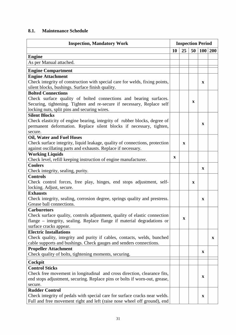
8.1. Maintenance Schedule
Inspection, Mandatory Work Inspection Period
10 25 50 100 200 Engine As per Manual attached. Engine Compartment Engine Attachment Check integrity of construction with special care for welds, fixing points, silent blocks, bushings. Surface finish quality.
x
Bolted Connections Check surface quality of bolted connections and bearing surfaces. Securing, tightening. Tighten and re-secure if necessary, Replace self locking nuts, split pins and securing wires.
x
Silent Blocks Check elasticity of engine bearing, integrity of rubber blocks, degree of permanent deformation. Replace silent blocks if necessary, tighten, secure.
x
Oil, Water and Fuel Hoses Check surface integrity, liquid leakage, quality of connections, protection against oscillating parts and exhausts. Replace if necessary.
x
Working Liquids Check level, refill keeping instruction of engine manufacturer. x
Coolers Check integrity, sealing, purity.
x
Controls Check control forces, free play, hinges, end stops adjustment, self-locking. Adjust, secure.
x
Exhausts Check integrity, sealing, corrosion degree, springs quality and prestress. Grease ball connections.
x
Carburetors Check surface quality, controls adjustment, quality of elastic connection flange – integrity, sealing. Replace flange if material degradations or surface cracks appear.
x
Electric Installations Check quality, integrity and purity if cables, contacts, welds, bunched cable supports and bushings. Check gauges and senders connections.
x
Propeller Attachment Check quality of bolts, tightening moments, securing.
x
Cockpit Control Sticks Check free movement in longitudinal and cross direction, clearance fits, end stops adjustment, securing. Replace pins or bolts if worn-out, grease, secure.
x
Rudder Control Check integrity of pedals with special care for surface cracks near welds. Full and free movement right and left (raise nose wheel off ground), end
x

32
stops adjustment, rudder cable tensioning, clearance fits, securing. Adjust, replace worn-out parts, grease, secure. Flap Control Check free movement of flap control lever, stable bearing in every flap position, interlock pin wear. Replace worn-out parts, grease, secure.
x
Canopy – Open / Close Check quality and function of locks and hinges, canopy bearing. Adjust, replace worn-out parts, grease, secure.
x
Flight Control Instruments Check legibility, markings, attachment instruments in panel, installations, wiring.
x
Electric Installations Check quality, integrity and purity of cables, insulations, contacts and welds. Battery attachment, working condition.
x
Safety Belts Check fixing points rigidity, belt surface quality, adjustment. x
Fuel System Check leak-proof condition, fuel supply quality, fuel pumps and valve function, tank de-aeration. Replace fuel filters.
x
Parachute Rescue System Check general condition, attachment. Do mandatory work as per instructions of rescue system manufacturer.
x
Landing Gears Main Gear Check attachment rigidity, surface quality, degree of permanent deformation.
x
Wheels Check attachment, brakes condition, brake pads, disc quality, leak-proof condition. Attachment and purity of wheel spats.
x
Front Gear Check general condition, integrity, rubber damper, clearance, springing deflection, steering quality. Grease sliding bearings, replace rubber springs if worn-out.
x
Fuselage Check general condition, integrity. Antennas, lights and coverings attachment.
x
Wing Check general condition, surface quality, integrity, attachment, fittings, clearance. Ailerons and flaps condition, surface quality, hinges, clearance, securing. Controls condition, free movement, end positions, clearance. Pitot tube condition and attachment.
x
Tail Surfaces Rudder, Elevator Check general condition, hinges, movement, clearance, securing. x
HT Stabilizer Check general condition, attachment, fittings, securing. x
10 25 50 100 200
33
8.2. Aeroplane Repairs The owner of aeroplane is obliged to report to the manufacturer each damage which may has an influence on an airframe strength or flight qualities. The manufacturer determines a way of repair. Minor repairs are the repairs of those parts, which do not participate substantially in the aeroplane function and stiffness. Among the permitted repairs are: - the lacquer repair - replacing the worn-out parts - repairing the tyres of the landing wheels These repairs can be carried out by the owner itself. Repairs of the torsion box, spars, wing or tail surfaces, landing gears and carrying load parts of airframe must be carried out in an special workshop. In case of surface finish repairs and changes the upper parts of aeroplane must always be kept in white. 8.3. Major Overhaul The major overhaul is carried out after 1200 flight hours but not later than 10 years after putting the aeroplane into operation, unless decided otherwise during regular technical inspections or by the company bulletin. The overhaul will be carried out in a special workshop. The overhaul and maintenance are carried out according to the instructions of the engine producer. 8.4. Anchorage of the Aeroplane The anchorage of the aeroplane is necessary in order to protect the aeroplane against eventual damage caused by the wind or wind blasts during parking outside the hangar. For the purpose, the aeroplane is equipped with threaded holes at the bottom side of the wing and at the tail skid. Threaded eye bars can be fastened into this points. 8.5. Cleaning and Care The aeroplane surface should always be treated by using suitable cleaning agents. The oil and grease rests can be removed from the aeroplane surface by suitable surface active substances or eventually by petrol. The cockpit enclosure should be cleaned only by washing using a sufficient water flow with an addition of suitable surface active substances. Never use petrol or chemical solvents.
34
Chapter 9 9. Weight, Centre of Gravity 9.1. Introduction 9.2. Empty Weight 9.3. Maximum Take-Off Weight 9.4. CG Range 9.5. CG Determination 9.6. Useful Load, Weight Table
35
9.1. Introduction The weight, useful weight and centre of gravity information is described in this chapter. 9.2. Empty Weight The weight of aircraft full equipped, without fuel and pilot. It is weighed as a total weight of all wheels weights. The empty weight of the ATEC 212 SOLO including ROTAX 582 DCDI 2V and standard equipment with / without rescue system is
……………………………… kg 9.3. Maximum take-off weight
300 315 kg
Never exceed the maximum take-off weight
9.4. Centre of gravity range The aircraft CG including the pilot of kg without fuel is
% of MAC
The flight range of CG specified by manufacturer is
28 – 36% of MAC
Operation over this range is prohibited
36
9.5. Centre of gravity determination The aircraft has to be weighed at flight position including pilot and fuel. Weight on main wheels G1 (kg) Weight on tail wheel G2 (kg) Total weight G = G1 + G2 (kg) Wheel base xMW-TW = 3,7 (m) Distance from main wheel centre to leading edge of wing in root point xMW-LE = 0,19 (m) CG distance from main wheel centre xMW-CG = G2 * 3,7 / G (m) Length of MAC bMAC = 1,032 (m) Length of wing chord in the root area b = 1,19 (m) Back-swept MAC displacement sy = 0,158 (m) CG distance from leading edge of wing in root point xLE-CG = xMW-LE + xMW-CG = = 0,19 + G2 * 3,7 / G (m) Distance from CG to leading edge of MAC xCG-MAC = xLE-CG – sy = = 0,032 + 3,7 * G2 / G (m) xCG-MAC% = xCG-MAC * 100 / 1,032 = = 3,1 + 358,5 * G2 / G (%) 9.6. Useful weight, weight table
Useful weight is a difference between maximum take-off weight and the weight of empty aircraft. The useful weight by empty weight ………………………. kg is ………………………. kg. The weight table
Fuel tank 50 l 1 l = 0,775 kg
Pilot weight kg incl.5 kg luggage
CG % MAC Total weight of aircraft kg
¼ ………. 12,5 l ½ ………. 25,0 l ¾ ………. 37,5 l 1 ……….. 50,0 l


![[Tech-lubrication]Lubrication Inst for S15XXC2 …Tech-lubrication... · TYPES OF LUBRICANTS Barudan supplies Machine Oil and Bearing Oil with all new machines. White Lithium Grease](https://img.pdfslide.us/doc/110x75/5b485d827f8b9aa4148d7472/tech-lubricationlubrication-inst-for-s15xxc2-tech-lubrication-types-of.jpg)