Embed Size (px)
Citation preview

www.eecatalog.com/atca
Gold Sponsors
Affiliate Sponsor
Engineers’ Guide to AdvancedTCA® & MicroTCA®
Annual Industry Guide AdvancedTCA, MicroTCA and AdvancedMC solutions for telecom, Wi-Fi and WiMAX
Featured Products
The AdaxPacketRunner, HDC3, ATM4 & PacketAMC hosts a complete ATCA
subsystem for SS7/ATM and IP-networking
From Lyrtech: Perseus 601X, the first Virtex-6 AMC with a
VITA 57.1 expansion site
From Interphase: iSPAN 36701 Wireless Basestation AMC
Developers Heed the Bandwidth Explosion
New Standards Advance Telecom Evolution
The Sky is the Limit — extending ATCA into military applications
EECatalog

Interphase Corporation Toll free: 800.327.8638
Phone: + 1.214.654.500 www.iphase.com/LTE
H/W— your specs SW— Layers 1-3
API
Your Applicaton
Radio Head
+
=
+Jump start development of your LTE basestation
with the Interphase modular basestation on a card.
Basestation control Baseband PHY Pre-integrated, fully-compliant LTE (L2/3) protocol layers Radio interface & essential I/O
API Onboard overhead for your application
This highly integrated small footprint solution reduces latency, power, cooling, and cost plus resolves essential software licenses, so your small form factor basestation designs can take off ….
Emergency
Private Enterprise
Zero Footprint
Military
Contact us now about the COTS model to support your lab trials and demos or about a custom version for your unique application requirements.

Engineers’ Guide to ATCA® & MicroTCA Technologies 20102
Welcome to the 2010 Engineers’ Guide to ATCA® &
MicroTCA® Technologies
Content surge. Bandwidth explosion. 40 gigabits per second. If these hyperboles leave you feeling whiplashed, don’t worry: we’re right there with you. Now, more than ever, engineers are charged with meeting the world’s increasing, insatiable demand for data. Evolution is natural, but it doesn’t come easy. By leaning on AdvancedTCA, the backbone (and backplane) of telecommunications equipment, vendors are deploying new products to meet the needs of knowledge workers and consumers.
In this issue, embedded developers and tech specialists con-verge for a roundtable discussion about trends driving ATCA and MicroTCA development. Then, in “The Sky is the Limit,” Christian Engels of Emerson Network Power argues that ATCA, as an open system, is best suited for military appli-cations. And four experts explain why “higher throughput, lower power, and restricted radiation will be the keystones of tomorrow’s wireless communication.” Lastly, Marc DeVinney of Interphase takes a quick look at how silicon advancements have yielded bsestation applications on single Systems on a Chip (SoC).
This is your guide to the expanding world of ATCA and MicroTCA products, services and vendors, whether you’re looking for fresh editorial content or targeted ads. Get caught up to speed. And as always, don’t forget to send feedback, thoughts and comments to [email protected].
As your work through the future, do not forget to send your feedback, thoughts and comments to:
Cameron BirdEditor, EECatalog.com
P.S. To subscribe to our series of Engineers’ Guides for embedded developers and engineers, visit:
www.eecatalog.com/subscribe
Engineers’ Guide to ATCA® & MicroTCA® Technologies 2010www.eecatalog.com/atca
VP/Associate PublisherClair Bright [email protected](415) 255-0390 ext. 15
EditorialEditorial DirectorJohn Blyler [email protected](503) 614-1082
Creative/ProductionGraphic DesignersKeith KellyBrandon Solem
Production Coordinator Spryte Heithecker
Online DirectorJeff Cheney
Advertising/Reprint SalesVP/Associate Publisher Embedded Electronics Media GroupClair Bright [email protected](415) 255-0390 ext. 15
Sales ManagerLisa Brayer [email protected] (415) 255-0390 ext. 21
Marketing/CirculationJenna Johnson
To Subscribewww.eecatalog.com/subscribe
Extension Media, LLCCorporate OfficePresident and PublisherVince [email protected]
Vice President, Sales Embedded Electronics Media GroupClair [email protected]
Vice President, Marketing and Product DevelopmentKaren [email protected]
Vice President, Business DevelopmentMelissa [email protected]
Special Thanks to Our Sponsors
The Engineers’ Guide to AdvancedTCA® & MicroTCA® Technologies 2010 is published by Extension Media LLC. Extension Media makes no warranty for the use of its products and assumes no responsibility for any errors which may appear in this Catalog nor does it make a commitment to update the information contained herein. Engineers’ Guide to AdvancedTCA® & MicroTCA® Technologies is Copyright ®2010 Extension Media LLC. No information in this Catalog may be reproduced without expressed written permission from Extension Media @ 1786 18th Street, San Francisco, CA 94107-2343.
All registered trademarks and trademarks included in this Catalog are held by their respective companies. Every attempt was made to include all trademarks and registered trademarks where indicated by their companies.


Engineers’ Guide to ATCA® & MicroTCA Technologies 20104
ContentsNew Standards Advance Telecom Evolution. .........................................................................................................................6
AdvancedTCA Innovations Poised to “Change the Game”
by Elma Bustronic Inc................................................................................................................................................................................. 8
Developers Heed The Bandwidth Explosion
by Cameron Bird ...................................................................................................................................................................................... 14
NAT-MCH
by NAT ..................................................................................................................................................................................................... 16
The Sky is the Limit
by Christian Engels .................................................................................................................................................................................. 20
Online & Offline: Industry Websites + Events .............................................................................................. 23
Tomorrow’s Wireless Communication Requires Higher Throughput and a Smaller Energy Budget
by Liesbet Van der Perre, Wim Van Thillo, Antoine Dejonghe, and Joris Van Driessche ........................................................................ 23
Winning Technology for Small Footprint Wireless Basestation Designs
by Marc DeVinney ....................................................................................................................................................................................48
Products and Services
Hardware
Blades
Adax, Inc.
AdaxPacketRunner ................................................................ 27
Emerson Network Power
ATCA-7365 & ATCA-7365-CEProcessor Blades .................... 28ATCA-7367 High Performance Processor Blade ................... 28ATCA-F140 40G ATCA Switch Blade ..................................... 29
Pinnacle Data Systems, Inc.
ATCA-F1 Dual AMD Socket F AdvancedTCA Blade .............. 30ATCA-RT01 AdvancedTCA RTM with Video and Storage .... 31
Boards / Board Accessories
Adax, Inc.
ATM4-AMC ........................................................................... 32HDC3 ..................................................................................... 33PacketAMC (PktAMC) ........................................................... 34
Boards / Smallform Factor
Interphase
iSPAN 36701 Wireless Basestation AMC ............................ 35
LeCroy Corporation
LeCroy’s PCI Express® Protocol Analysis and Test Tools ......... 36
Scan Engineering Telecom
SMCH-102 Cost-effective MCH for MicroTCA systems .......... 37
SAMC-203 High-performance AdvancedMC storage module ...... 38SAMC-504 Quad-Core AdvancedMC Processor module ......... 39
Development Platform
Emerson Network Power
Katana® 2000 Commercial ATCA Bladed Server .................. 40
Enclosures
Elma Electronic Inc.
AdvancedTCA System Platforms .......................................... 41
Schroff
MicroTCA Enclosures ............................................................ 42
MicroBlade
MicroBoxPlus 1U ................................................................... 43MicroBoxPlus 2U ................................................................... 44
Packaging
Elma Electronic, Inc.
AdvancedTCA® and MicroTCA® System Platforms .............. 45
Power Supply Modules
MicroBlade
Panther 380 and 760 MicroTCA DC Power Module ............. 46Puma 300, 600 and 900 MicroTCA AC Power Module ......... 47


Engineers’ Guide to ATCA® & MicroTCA Technologies 20106
EECatalog INDUSTRY FORECAST
Predictions, even those built on solid methodological
foundations, often collapse in the face of unforeseen
variables. But one selection pressure, as Rob Pettigrew of
Emerson Network Power reminds in our annual industry
roundtable (see page TK), remains. “The introduction of
ATCA technologies will be evolutionary,” he notes. Still,
analysts are split on the prospects of ATCA’s evolution.
Here, we excerpt some appraisals hot, cold lukewarm and
every temperature in between:
From Heavy Reading’s “ATCA, AMC & MicroTCA” forecast
(www.heavyreading.com):
• The ATCA sector will grow from $798 million in 2009
to $6.7 billion in 2012 - a compound annual growth rate
of 103 percent over that span. With second-generation
platforms already in production, ATCA-based system
shipments are growing quickly.
• The COTS share of the ATCA market will fall below 50
percent by 2010, before recovering in 2011. As companies
ship more systems based on in-house ATCA components,
the COTS market share will fall, before recovering
slightly as the market matures.
• ATCA-based 2G/3G/4G wireless systems from multiple
equipment vendors are delivering new flexibility for car-
riers. By using a single platform for several generations
of wireless technology, network equipment providers
can offer 2G and 3G solutions now, with simple upgrades
to Long Term Evolution (LTE) or WiMax when required.
• IP Multimedia Subsystem (IMS), LTE, and Evolved
Packet Core (EPC) systems based on ATCA are now being
used for trials and network deployments. ATCA market
growth is partly being driven by carrier investment in
these key technologies.
• More than 200 AMC modules are now available from 35
vendors, with several new market entrants. AMCs are
now available for central processing unit (CPU), digital
signal processor (DSP), storage, packet processing, net-
working, and general input/output (I/O) applications.
From Light Reading’s analysis, “AdvancedTCA Makes
Headway,” on the potential of a new wireless infrastruc-
ture based on ATCA (www.lightreading.com):
“The idea behind the standard is that blades from one
vendor could be incorporated into a chassis made by
another vendor. ‘Today, if you look, you have a separate
infrastructure for ATM, IP, wireless, storage, PSTN
switches, and so on,’ says Danny Berko, BATM’s product
manager. ‘One day all services could be integrated into a
single platform. The concept is any protocol on any card on
any slot on an AdvancedTCA platform.’
Whether this level of interoperability is a practical
reality remains to be seen. Establishing standards and
implementing them is a good start, but service providers
will probably take a lot of convincing before they’ll start
mixing different vendors’ cards in the same chassis. All
the same, the existence of the standards will probably help
drive down equipment prices, because it will lead to greater
commoditization of subystems as well as the components
that go into them.”
New Standards Advance Telecom EvolutionForecasters point to wireless, 4G, and interoperability as reasons to cheer on ATCA - with cautious optimism.

»
Hosted by Light Reading
»
Hosted by Femto Forum
»
»
Hosted by 3G Americas
»
»
Hosted by Award Solutions
»
Hosted by TM Forum
»
»
Hosted by TM Forum
»
»

Engineers’ Guide to ATCA® & MicroTCA Technologies 20108
There are up and coming products for ATCA that are ready to take
the industry by storm. These include orthogonal backplanes,
SerDes test units, and 40G ATCA backplanes.
Orthogonal BackplanesThe orthogonal concept is a completely different approach to
backplane design. Developed with partner Z-Plane Inc, Bustronic
has a backplane with the high-speed routing across the rear of the
backplane (see photo 1 example), essentially the z-axis of the board.
With the high-speed signals taken off the backplane and onto rear
pluggable “links” that carry point-to-point signals directly, there
are virtually no negative stub effects on the backplane. The result is
rates of 80-100 Gbps across the backplane.
The Bustronic ATCA backplane with Z-Plane Links offers up to
triple the performance of traditional versions of the architecture
at a reduced cost. This is achieved using the Z-Plane Links which
carry the high-speed, long-trace signals via a small, low-profile
PCB board that plugs directly into the rear of the backplane. The
basic clock signals and shorter trace lines are left on the back-
plane. This orthogonal link approach allows the backplane to
have only 10 layers, compared to a traditional ATCA backplane
which may have 18-24 layers or higher. Characterization studies
confirm that the signal integrity of the backplane with the Z-
Plane Links can produce solid results at higher data rates than
conventional backplanes.
The ATCA community is moving to 40 Gigabit/second speeds
per channel across the backplane. The version with the Z-Plane
Links will help ATCA backplanes achieve these very high perfor-
mance levels, while keeping costs low. The Z-Plane Links feature
an adapter with guide pins used to firmly secure the rear plane
PCB in place and provide strain relief. This adapter has a short,
impedance-matched connection between the rear “Z dimension”
PCB (Link) and the backplane connector. They also have staggered
arrays, so they can be stacked adjacent to one another, and they
come in press-fit pin or compliant pin termination depending on
the backplane thickness.
SerDes Test Units for VPX BackplanesBustronic currently offers SerDes test units for VPX backplanes.
With the multi-gigabit speeds in VPX and ATCA, designers will
need to test their boards, backplanes, and systems. Whether you
are an integrator/end-user or vendor, you need to ensure that the
product works properly with clean signals. The DJ1000/1600 tests
the bit error rate (BER) of the backplane, plug-in module or full
interconnect path. It can provide Eye Diagrams and other modules
to troubleshoot problems with the system. Pre-emphasis tuning
can also be applied to optimize signal outcomes. VPX versions are
now available and ATCA versions are on the roadmap.
40G ATCA BackplanesThe efforts for 40G ATCA backplanes are underway in PICMG and
Bustronic is heavily involved. By 40G, we mean 4x channels of 10
Gbps signals. To come up with a standard, the industry is doing a
close review of the IEEE 802.3-2008 requirements for 10-Gbit Eth-
ernet Base-KR. The PICMG community needs to come to consensus
on what parameters should be specified as part of compliance and
what their actual limit values should be. IEEE’s 802.3-ba work on
40G has also hit some snags, especially with regards to crosstalk
quantification. However, progress is being made and late in the
year, we should have the issues resolved and provide proven perfor-
mance at 40G speeds.
CONTACT INFORMATION
Elma Bustronic Inc.44350 Grimmer Blvd.Fremont, CA 94538 USA510.490.7388 [email protected]
by Elma Bustronic Inc.
AdvancedTCA Innovations Poised to “Change the Game”
Bustronic ATCA Backplane with rear Z-Plane Links.
SerDes test unit that can be used for VPX, ATCA, and other high-speed serial architectures.
Example of 40G AdvancedTCA backplane.


JTAG
GTX (×8)
FMC DP[0–7]
LVDS I/Os (×76)
LA[00–33] P-N (full)
HA[00–23] P-N (full)
HB[00–17] P-N
High-pin-
count FMC
AMCDDR3
MicroBlaze code
128 MB
DDR3 SODIMM
1 GB (by default)
QDR2 SRAM
Bank 1: 9 MB
QDR2 SRAM
Bank 2: 9 MB
Flash memory
64 MB
Low-jitter
clock switch
Xilinx Virtex-6
LXT or SXT
JTAG switch
Mestor interfaceJTAG interfaces: FPGA/IPMI
User I/Os: LVDS ×14, clock ×1
FPGA UART interface (serial TX and RX)
FMC clock (×4)
TCLKA, B, C, D
I2C SMT
jumper
Module management
controller (MMC) IPMI (I2C)
Fabric clock
Port 0
Port 1
Port 2
Port 3
Ports 4–7
Ports 8–11
Ports 12–15
Ports 17–20
GigE (×1)
GigE (×1)
Storage (×1)
Storage (×1)
PCIe/SRIO/XAUI (×4)
PCIe/SRIO/XAUI (×4)
LVDS I/O (×4)
RTM MGT (×4)
UA
RT
Use
r I/O
UA
RT
JTAG chain
JTAG
FPGA JTAG
IPM
I JTAG
Perseus 601X functional block diagram
Fabric switch
Perseus 601XThe first Virtex-6 AMC with a VITA 57.1 expansion site
High-performance, high-bandwidth, low-latency processing applications at your fingertips
Outstanding featuresMid-size AMC for μTCA and AdvancedTCA platforms
Choice of powerful LXT and SXT Virtex-6 FPGAs
High-pin-count VITA 57.1 FMC expansion site for I/Os
DDR3 SODIMM interface to upgrade system memory
Supports multiple switch fabrics — PCIe, SRIO, XAUI, GigE
Comprehensive line of software development tools
The Perseus 601X advanced mezzanine card (AMC) is designed around the powerful Virtex-6 FPGA, combining unsurpassed fabric flexibility and a colossal external memory, as well as benifiting from multiple high-pin-count, modular add-on FMC-based I/O cards.The Perseus is designed for high-performance, high-bandwidth, low-latency processing applications. The card also takes full advantage of the Virtex-6 FPGA’s power, which, when combined with Lyrtech’s advanced so ware development tools, makes the Perseus perfect for reducing size, complexity, risks and costs associated to leading-edge telecommunications, networking, industrial, defense and medical applications. On top this, the Perseus’ FMC expansion site offers almost endless I/O possibilities.

Mid-size configuration
Full-size configuration
1 GB DDR3 SDRAM SODIMM
9 MB QDR2 SRAM banks
(2nd bank under heat sink)
Full-size AMC
Mid-size AMC
Mestor expander
troubleshooting interfaces
Full-size AMC panel shown. Mid-size AMC front panel also available.
64 MB NOR flash memory
containing FPGA images,
MicroBlaze boot code, user code
128 MB DDR3 SDRAM
(MicroBlaze memory)
High-pin-count FMC interface (VITA 57)
FMC front panel
The Perseus at a glanceThe Perseus’ high-performance Virtex-6 LXT and the SXT platform families are supported. They both offer the flexibility and acceptable tradeoffs between high-performance logic and massive digital signal processing power.
Mid-size and full-size configurations• Support for AMC R2.0 and R1.0 through • an onboard clock switchGTX base clocks — 100 MHz, 125 MHz, • and 625 MHz (PCIe/GigE/XAUI/SRIO)Fabric clock — RX or TX (100 MHz • PCIe, default)IPMI controller (based on the • AVR version of the Pigeon Point AdvancedMC MMC)FPGA and IPMI JTAGs on the Mestor interface•

Debugging options
Mestor-to-FPGA JTAG adaptorConnected to a Xilinx JTAG pod, you can easily debug your software through USB.
Mestor expanderOffers a wide variety of debugging interfaces right on the Perseus’ full-size front panel — FPGA JTAG and IPMI, USB UART, LVDS I/Os and more.
BackplaneYou can easily debug your software through the card’s backplane FPGA JTAG
Debugging interfacesThe FPGA and IPMI JTAGs are available from the standard AMC backplane or from the onboard Mestor interface. Lyrtech offers two optional Mestor debugging modes:
Processing powerThe Virtex-6 family of FPGAs is the high-performance silicon foundation for targeted design platforms. Consuming 50 % less power and costing 20 % less than the previous generation of FPGAs, the Virtex-6 family is built with the right mix of programmability, integrated blocks for digital signal processing, memory and connectivity support — including high-speed transceiver capabilities — to satisfy the insatiable demand for higher bandwidth and higher performance.
Software development toolsThe Perseus comes with a comprehensive set of integrated, multilayer so ware development tools that offer users a choice of environments — from a base-level hand-coded design environment to a high-level graphical model-based design environment.
Commonly referred to as the BSDK, this kit offers reconfigurable FPGA components and reference designs, along with the infrastructure to implement, simulate, synthesize, validate, and
deploy complete applications on the card’s Virtex-6 FPGA. This development kit takes care of the tiresome burden of reinventing interface drivers for the FPGA, freeing you to focus on unique, value-added development.

Optional kit
Model-based design kit
(MBDK)
Board software development kit (BSDK)
Standard Lyrtech
software development tools
High-level, optional
software development tools
The MBDK is optional and allows you to easily design high-performance digital signal processing systems within the card’s FPGA with the MATLAB/Simulink design environment and extensive DSP IP libraries from Xilinx.For even greater flexibility, System Generator
for DSP supports MicroBlaze so processor cores, which allows using high-level abstractions that can be automatically compiled into the FPGA without losing any performance over VHDL designs. Use it with ChipScope Pro to debug your applications.These features, combined with the capabilities of the Virtex-6 FPGA, make it simple for designers to harness the parallel processing power of an FPGA.
The Perseus’ MBDK edgeInterface and integrate with the interface libraries • supplied with the Perseus in no time flat.Benefit from all-integrated configuration, simulation, and • code generation advantages of the Perseus’ MBDK.Save precious development time using the debugging • tools part of the MBDK, namely recording/playback tools and shared-memory GigE/PCIe HIL co-simulation tools.Configure the Perseus in a snap with its graphical • configuration tools.Draw the maximum out of the Perseus’ streaming • interface between the FPGA and host computer running MATLAB (GigE/PCIe).Further your understanding of the Perseus with its • extensive library of demonstrations and applicative examples.
Optional FMC modulesThe Perseus benefits from a growing pool of FMC modules, among which the following.
ADAC250This module is designed around the high-performance A/D and D/A conversion technology from Texas Instruments — it integrates one dual, 14-bit, 250 MSPS analog-to-digital converter (ADS62P49) and a dual, 16-bit, 1 GSPS digital-to-analog converter (DAC5682Z; also capable of a 2–4× interpolation mode). Combined with multiple clocks and synchronization modes, the ADAC250 is at its best in DSP applications such as so ware-defined radio (SDR), advanced telecommunications (MIMO systems, cognitive radios, beamformers, LTE, WiMAX), signal intelligence (SIGINT), radar, sonar, and medical imaging applications.
SFP+2Dual, 10 Gbps SFP+ interface on a high-pin count FMC module. Board under development. Contact Lyrtech for availability.
A variety of other FMC modules are also underway. Don’t hesitate to contact us for more information.
Contact us for details at [email protected] visit us on the Web at www.lyrtech.com.

Engineers’ Guide to ATCA® & MicroTCA Technologies 201014
EECatalog SPECIAL FEATURE
To ease the flow of data gushing through telecommunica-
tion networks, President Obama recently called on the U.S.
government to free up part of the wireless spectrum. ATCA
and MicroTCA platforms are becoming increasingly important
players in dealing with the bandwidth explosion. To get a pulse
on key trends in development, EECatalog interviewed Louis
Perez, director of North American engineering at Interphase;
Rob Pettigrew, director of marketing and communications for
embedded computing at Emerson Network Power; and Justin
Moll, director of marketing at Elma Bustronic.
EECatalog: What major trends are driving engineering of
ATCA/MicroTCA systems?
Louis Perez, Interphase: 4G, Carrier Grade
Ethernet, and Deep Packet Inspection (DPI)
applications. Another, specially for MicroTCA,
is cost reduction.
Rob Pettigrew, Emerson: Clearly the mega-
trend in the industry is the insatiable subscriber
demand for bandwidth, largely in wireless
networks. This is driving the need to develop
and deploy new infrastructure equipment. The
decision to deploy on ATCA systems is driven
by time-to-market, giving telecom equipment makers the
ability to rapidly develop and deploy systems with the latest
technology.
Justin Moll, Elma Bustronic: One of the
main drivers is the push, or need for more
bandwidth in the systems from several points.
With the popularity of mobile devices, social
networking, surge in video usage, etc., the data
demand is really putting a strain on today’s
networks. These same demands are driving military and aero-
space to consider ATCA/uTCA to meet the need for Integrated
Communication Systems, Command and Control, Next-Gen
BMD and Radar Tracking. Historically, tier two customers
with telecom and enterprise applications have leveraged stan-
dards like ATCA and uTCA but we have seen an increased move
to outsource from Tier one players with higher volume needs
as well.
EECatalog: How is 4G impacting development?
Perez: 4G requires equipment that’s common to ATCA and
MicroTCA. This is stimulating creative cost optimized solu-
tions for 4G. The volumes will drive cost down further. 4G also
requires an increase of backplane throughput and processing
performance.
Pettigrew: Our customers are developing 4G infrastructure
now. For LTE/EPC, AdvancedTCA systems are a great fit for
both control plane (MME) and data plane (S-GW / P-GW) ele-
ments, creating strong demand for current 10Gbps integrated
systems, and next generation 40Gbps systems.
Moll: ATCA has the inherent attractiveness of being an open
specification, with wide vendor support, a proven and suc-
cessful architecture, and has the forward performance push
into speeds like 40 gigs and even beyond that. It’ll be very
attractive as 4G comes online.
EECatalog: In Telecom, the leap from 10 to 40 Gbps (gigabit
per second) ATCA shelves is set to begin this year, will a full-
fledged roll out in 2011. What are the challenges of building
these new shelves? And how are designers mitigating these
concerns?
Perez: Maintaining signal quality is a challenge in building
these new shelves, and designers are focused on solving these
issues.
Pettigrew: The biggest challenge currently is that the 40Gbps
ATCA standards are not yet ratified. While we are confident
that the physics are well understood, what remains is the
allocation of insertion loss and cross talk budgets between
the various system elements (backplane, fabric hub board,
and payload board). In the absence of such budget allocations,
early developers are forced to be very conservative with their
assumptions.
As fabric switches and payload blades come to market, we can
assume that there will inevitably be interoperability issues
between products from different vendors. These issues will be
mitigated through interoperability testing by bodies such as
PICMG and the CP-TA.
Of course, customers looking to reduce their risk during this
interval will be able to mitigate this by purchasing system-level
by Cameron Bird
Developers Heed The Bandwidth ExplosionDemand for faster data transfer coincides with upgrades to the telecom infrastructure.

www.eecatalog.com/atca 15
EECatalog SPECIAL FEATURE
redundancy and system management. However, cost alone can
limit it to certain apps. Recently, some developers have moved
to simpler versions of MicroTCA without separate intelligent
power supply modules and without inherent redundancy.
Instead, active circuitry can be designed on the backplane to
account for “intelligent” power delivery to each slot, rather
than counting on a more complex hot-swappable power unit.
Simpler versions can now reach more markets, because at this
level it’s at a competitive price point. MicroTCA is now also
seeing more competition from architectures such as 3U VPX
and purpose-built solutions from various vendors.
EECatalog: Looking ahead, what other ATCA/MicroTCA-
based technologies do you see as the next game-changers?
Perez: Mobile and 3D Video applications are going to be the
next game-changers driving ATCA/MicroTCA based technolo-
gies.
Pettigrew: I believe the introduction of ATCA technologies
will be evolutionary, driven by the network demands for
more compute performance and bandwidth capacity, and the
availability of technologies to meet those demands. For ATCA
fabrics, look for the introduction of 40Gbps switches this
year, with future products delivering more I/O and packet
processing capabilities. For payload, the focus will remain on
keeping up with the latest general purpose server and spe-
cialized packet processing technologies, with introduction of
40Gbps payload next year. And since computing blades never
seem to get any cooler, look for chassis with improved airflow,
cooling and acoustics.
Moll: 40G ATCA Backplanes will be a huge boost in bandwidth.
We’ll also likely see more of ATCA in mil/aero applications and
perhaps some hybridized rugged versions. Aside from 40G
efforts, Elma has been involved in an orthogonal approach
with our partners at Z-Plane Inc. So what we’ve done is develop
a backplane with links on the rear. If you think of a backplane
with X and Y axes, these links are on a Z axis. They can carry
the high-speeds or the worst-case traces. This can help take a
backplane - say with 24 layers - to 8 or 10 layers. When you’re
going from higher to lower layers, the stub effect from longer
stubs will be minimized. Ultimately, you can get triple the
performance and the costs are expected to drop to half or stay
about the same. We’ve tested about 75 gigs across the links, so
we have much higher performance across the total backplane
solution.
Cameron Bird is editor of EECatalog.com.
products, with chassis, switches and payload boards developed
by the same vendor.
Moll: There have been claims of capability up to 40Gbps.
Maybe a card with four links at ten gigs each has been proven
at those speeds, but what about the full interconnect path -
from card going across backplane to a card? The industry is
still working out those issues. The IEEE P802.3ba task force is
working on an effort to achieve 40 gigs across the backplane,
along with the PICMG community. It’s still difficult to produce
a backplane and/or daughter card that will replicate the card
as it was simulated. We need to make decisions on the total
channel loss, and there needs to be a consensus of method-
ology in standardization in general on a few things. More time
needs to be invested in areas such as the 10GBase-KR and
40GBase-KR4. In short, there just needs to be more time and
development. We expect late this year that the PICMG 3.1 Rev
2 committee will have something more solidified and the IEEE
P802.3ba just announced ratification in June of this year. Until
then, companies can claim 40 gigs across an ATCA backplane,
but we need to be sure that, like I said, the same methods are
standardized and agreed upon. We’re very confident we’ll get
there as an industry, probably by the end of this year, but that’s
not all settled yet.
EECatalog: About a year ago, the PCI Industrial Computer
Manufacturers Group boasted that air-cooled rugged MicroTCA
would extend “the use of the platform beyond its original
Telecom focus.” How successful has this initiative been?
Perez: MicroTCA systems has had successes in ruggedized
applications in conduction cooled and fanless environments.
Ruggedized MicroTCA systems are a perfect fit for defense and
aerospace applications. In the past year, we have seen growth
in this market segment.
Pettigrew: The MicroTCA market continues to evolve. But I
think it’s still a bit early to determine how well it will succeed
in markets requiring ruggedized systems.
Moll: Rugged MicroTCA has size and performance possibilities
that are quite intriguing. The challenge has been to maintain
the advantages of the AMC COTS ecosystems while rugged-
izing the architecture to meet the environmental demands of
a deployed environment. As the cost and the complexity of the
solution increase other competing architectures become attrac-
tive. We’ll have to see whether the market will accept some of
the inherent compromises that the specification might have
to achieve a certain ruggedness and cooling level and if the
competing technologies will take a strong foothold.
MicroTCA is very attractive with its smaller footprint and
functionality. The architecture in general reaches a wide range
of applications. Initial versions were designed with high-level

Engineers’ Guide to ATCA® & MicroTCA Technologies 201016
N.A.T. Gesellschaft für Netzwerk- und Automatisierungs-Technologie mbHKamillenweg 22 l 53757 Sankt Augustin, Germany l Phone: +49 2241 398 90 Fax: +49 2241 398 910 l [email protected] l www.nateurope.com
The N.A.T. MicroTCA Carrier Hub NAT-MCH is the central management and data switching engine for all MicroTCA systems.
The NAT-MCH is designed to provide any functionality as defined by the MicroTCA specification MTCA.0 R1.0, serving up to the maximum of 12 Advanced Mezzanine Cards (AMCs), 1-4 power units and two cooling subsystems.
Because of its scalable and flexible design the NAT-MCH can be used in any kind of MicroTCA system, supporting telecom and non-telecom environments as well as redundant and non-redundant architectures.
The mandatory carrier manager is realized util-izing the on-board Freescale ColdFire CPU. For MicroTCA systems operated in a detached or stand-alone mode a shelf manager as well as a system manager can be provided, too.
Beside the intelligence the MCH base module incorporates a managed, non-blocking and low-latency Gigabit Ethernet L2 switch for base channel connectivity. Numerous options like a fabric switch module for PCI-Express (PCIe), Serial Rapid I/O (SRIO), 10 Gigabit Ethernet or a clock distribution module for telecom environments are available as mountable daughter boards.
Serial Rapid I/O- - - - - - - - - - - - - - - - - - - - -
10GigaBit(XAUI)- - - - - - - - - - - - - - - - - - - - - - - - -
GigaBit Ethernet- - - - - - - - - - - - - - - - - - - - - - - - -
PCI Express- - - - - - - - - - - - - - - - - - - - -
Telecom clock and FCLKSerial Attached SCSI- - - - - - - - - - - - - - - - - - - - - - - - -
Following the building block model the NAT-MCH can be individually arranged to meet the exact system requirements. A comprehensive software support like a Java based GUI interfacing to the Open HPI compliant top level API of the NAT-MCH completes the product and makes it an ideal choice for any AMC based MicroTCA solution.
NAT-MCH

www.eecatalog.com/atca 17
Technical Data
Overview and PurposeThe NAT-MCH is a MicroTCA (uTCA/MTCA) Carrier Hub in the form factor of a single width and mid size or full size Advanced Mezzanine Card (AMC). It provides the cen-tral management and data switching entity for all MicroTCA systems. The NAT-MCH comprises of a base module and numerous optional daughter cards which can be mounted on the base module. The NAT-MCH is MicroTCA.0 R1.0 compliant and delivers switching and hub functional-ity for the various system fabrics as defined in the AMC.x standard series, i.e. 1Gigabit Ethernet, PCI-Express (PCIe), Serial Rapid I/O (SRIO), 10Gigabit Ethernet (XAUI) or Serial Attached SCSI (SAS). The NAT-MCH can also provide a centralized clock distribution to all AMCs in the system.
CPU, memory and O/SThe NAT-MCH base board is equipped with a CPU of the Freescale ColdFire family of processors. The CPU operates at core fre-quency of 200 MHz. The NAT-MCH provides 32/64MB SDRAM and 16/32/64MB FLASH memory. The operating system used with the NAT-MCH is OK1 or Linux.
Gigabit Ethernet Hub and Switchand 10GbE (XAUI) SupportThe Gigabit Ethernet Switches incorporated in the NAT-MCH both provide a layer 2, non-blocking, low-latency Gigabit Ethernet switches, supporting VLAN as well as a port based rate control. The NAT-MCH supports Fabric A (1GbE) and Fabrics D-G (10GbE, XAUI) according to MicroTCA.0 R1.0 and PICMG SFP.1 R1.0, serving up to 12 AMCs as
well as the update channel from the second MCH in redundant environments. Also supported are uplink ports at the front panel of the NAT-MCH in order to interconnect to other carriers, shelves or systems.
PCI Express Hub and SwitchThe PCI Express Switching option allows PCIe connectivity for up to 12 AMCs at PCIe rates from x1 to x4. The used PCIe chipsets provide a Quality of Service (QoS) module and are configurable in terms of a non-transparent port for multi-Host sup-port. The PCIe option can optionally provide a PCIe clock by a Spread Spectrum Clock (100MHz mean) or a fixed 100MHz clock. The clock can be provided compliant to HCSL or MLVDS signaling levels. The PCIe hub provides clustering support for two independant clusters of 6 slots each.
SRIO Hub ModuleAlternatively to PCIe or 10GbE (XAUI) the NAT-MCH can be equipped with a Serial Rapid I/O (SRIO) daughther board to support contention less point-to-point connectivity between up to 12 AMC modules. The SRIO hub supports x1 and X4 fat pipe transport density.
Clock DistributionBesides the PCIe clock the NAT-MCH also offers a sophisticated clock distribution module for special requirements, i.e. as by comms applications. Thus the module al-lows a flexible selection of the telecom and non-telecom clocking structures as defined in MicroTCA.0 R1.0.
The on-board Stratum 3 type PLL sources its clock reference configurable from either any of the 12 AMCs or from an external clock via the front panel BNC type connector. With respect to the PCIe clock the NAT-MCH sup-ports both signal levels, HSCL as required by PCI-SIG and MLVDS as requested by the MicroTCA.0 specification.
ManagementThe NAT-MCH incorporates a MicroTCA Carrier Management Controller (MCMC) which supports and manages up two 12 AMCs, 2 cooling units and 1-4 power units. Special care has been taken to support numerous aspects of system architectures, i.e. E-Keying, redundancy, load sharing, clocking, fail-over scenarios or system integ-rity. External system or shelf managers can connect to the NAT-MCH through and of the Ethernet front panel ports. For remote control and visualization N.A.T. holds its JAVA based application NATView available. Like any other remote management tool (i.e. ipmitool (open source) or any tool based on the HPI recommendation of the Service Availability Form (SAF)) NATView accesses the NAT-MCH via the Remote Management Control Protocol (RMCP) as requested by the MicroTCA.0 specification.
ConfigurationThe NAT-MCH can be configured comfort-ably by the included web interface using any standard web browser or by the command line interface via serial connection (RS232) or a Telnet connection.
Engineers’ Guide to ATCA® & MicroTCA Technologies 201018
NAT-MCH-Mezzanine Modules
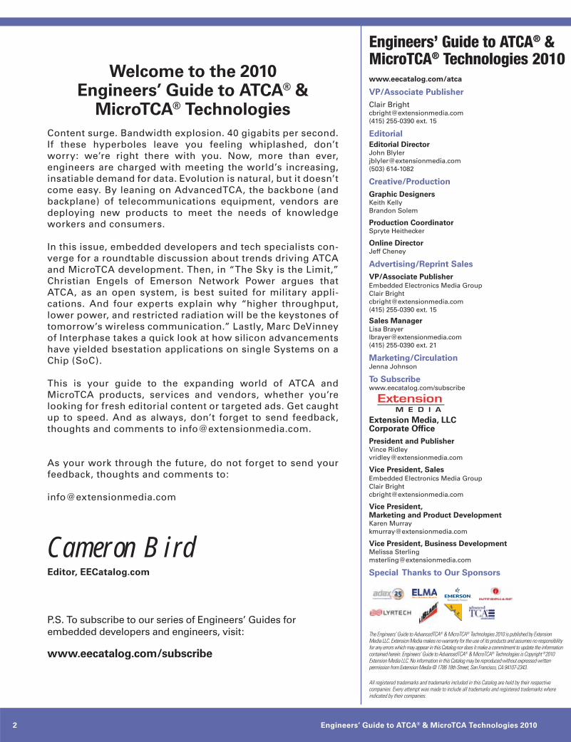
Clock Mezzanine
The Clock Mezzanine Module allows a flexible selection of the telecom and non-telecom clocking structures as defined in MicroTCA.0 R1.0. The on-board Stratum 3 type PLL sources its clock reference con-figurably from either any of the 12 AMCs or from an external clock via the front panel BNC type connector. In conjunction with the PCIe Hub module it provides a PCIe compliant fabric clock (FCLKA) to all AMC slots. This can be either a 100MHz fixed or 100MHz Spread Spectrum clock (SSC). The PCIe clock can be provided compliant to HCSL or MLVDS signaling levels.
Key Features:Support of AMC clocks CLK1, CLK2 −and CLK3 for up to 12 AMCsUpdate clock for a second NAT-MCH−in a redundant systemsReference clock In/Output on −face plateStratum 3 type PLL clock source −for telecom applicationsVariable switching and distribution −of clocks by onboard FPGAReference for the Stratum 3 PLL can−be either CLK1 or CLK2 from any AMCor sourced from the front panelPCI Express compliant clock signal can−be distributed via FCLKA to all 12 AMCs (only supported with an installed PCI Express Hub-Module)
PCIe Hub Mezzanine
The PCI Express Switching Mezzanine is an AMC.1 compliant module for the NAT-MCH that enables users to add scalable high bandwidth, non-blocking interconnection to a wide variety of applications including servers, storage, video streaming, blade servers and embedded control products. The PCIe Hub module supports full non-
transparent bridging functionality to allow implementation of multi-host systems and intelligent I/O modules in applications such as communications, storage and blade servers.
Key Features:support for 6 (option -X24) or 12−(option- X48) AMC modules, Fabrics D-Gnon-blocking switch fabric−built of two PLX PEX 8532 chips (-X48)−high density x8 interconnect between−chips to prevent performancebottleneckupstream port configurable to any −of the 12 AMC slotsPCIe hot plug support for each −AMC slotsecondary (failover) host possible−clustering support, two clusters of −6 AMC modules each can be operated individually, each having its own root complexsupports x1 and x4 width ports to −any AMCconfiguration option for Spread−Spectrum Clock (SSC) or 100MHz fixed PCIe clockPCIe clock can be provided as Fabric−Clock (FCLKA) to the AMC slots
SRIO Hub Mezzanine
The SRIO Mezzanine module provides a non-blocking high performance data switching functionality for up to 12 AMCs. The non-hierarchical structure of SRIO allows for superior bandwidth data communication between each end point. Additonally, with SRIO data integrity and health checks are performed by hardware.
Key Features:flexible port width: X1 and X4−12.5 GBit/sec Bandwith per port (X4)−80 Gbit/s aggregate bandwidth−operating baud rate per data lane −1.25 GBit/s, 2.5 GBit/s or 3.125 GBit/stransport layer error management −low latency packet transport −power down modes and routing −capabilities per port
− decentralised communication model:per-to-per
10GbE (XAUI) Hub Mezzanine
The NAT-MCH 10 GbE Hub Mezzanines provides high performance, low latency and robust Ethernet packet switching service for MTCA systems.
Key Features:10GbE Ethernet port for 12 AMC slots−2 Uplink ports on faceplate−per Port selction of:−
XAUI - 10GBase-CX42.5 GbE1 Gb
Link Aggregation (802.3− aad)240 Gbps bandwidth−
Security:MAC address security−Port access control (802.1x)−
Layer 2 Bridging Features:Spanning Tree (802.1D,s,w)−VLAN priority (802.1Q,P)−Link Aggregation (802.3− aad)Duplex Flow Control (802.3x)−user defined monitoring and −filter rules2 Uplink ports on faceplate−per Port selction of:
XAUI - 10GBase-CX42.5 GbE1 Gb
Link Aggregation (802.3− aad)240 Gbps bandwidth−
Security:MAC address security−Port access control (802.1x)−

www.eecatalog.com/atca 19
N.A.T. Gesellschaft für Netzwerk- und Automatisierungs-Technologie mbHKamillenweg 22 l 53757 Sankt Augustin, Germany l Phone: +49 2241 398 90 Fax: +49 2241 398 910 l [email protected] l www.nateurope.com
Technical Data NAT-MCH
CPU and memoryFreescale ColdFire 547x @ 200MHz−DRAM: 32/64MB−FLASH: 16/32/64MB−
IPMI and Compliance12 AMCs,−2 cooling units−1-4 power units−PICMG AMC.0 R1.0−PICMG 2.9 R1.0−
Supported Fabrics and ComplianceFabric A: Gigabit Ethernet
12 AMCsPICMG AMC.2 R1.0PICMG SFP.1 R1.0
Fabric B: Serial Attached SCSISerial ATAPICMG AMC.3 R1.0option available on request
Fabric D-G:PCI Express (PICMG AMC.1 R1.0)12 AMCs, x1-x4 eachSerial Rapid I/O (PICMG AMC.4)10GbE (XAUI) (PICMG AMC.2)
Clock DistributionTelecom: Stratum 3 PLL with reference−from either 1 of the 12 AMCs or external clock via front panel PCIe: Spread Spectrum Clock−(100MHz mean) or oscillator (100MHz fixed), HCSL or MLVDS signaling
Carrier ManagerManagement of up to 12 AMCs, 2 cooling units and 1-4 power units, supports redun-dant architectures and fail-over procedure
Shelf and System ManagerFor detached or stand-alone operation both managers are available on-board, hook-in for external managers via 100BaseT or 1GbE port at front panel or backplane GbE
Operating System and APIO/S: OK1, Linux−API: HPI compliant−
Indicator LEDs4 standard AMC LEDs−12 bi-colour LEDs for AMC slot stati−2 bi-colour LEDs for cooling units−2 bi-colour LEDs for power units−
Front Panel Connectors100 BaseT management connection−1 GbE system up-link for Fabric A−external clock reference (bi-directional)−serial debug connector−
NATView
Overview and PurposeNATView is an easy to use visualisation tool for any MicroTCA system that includes a NAT-MCH. NATView is operating system in-dependent and runs on any host computer internal or external to the MicroTCA system. NATView allows the user to view at and ma-nipulate the components of the MicroTCA system in a graphical way.
Operating System NATView is a JAVA based tool and thus independent of any host operating system. NATView can run on an host CPU internal or external to the MicroTCA system if it can execute SUN JAVA 1.5.
Linking to the NAT-MCHNATView connects to the NAT-MCH us-ing RMCP (Remote Management Control Protocol) as requested by the MicroTCA specification. The host part of the RMCP is included in NATView, so no additional pro-tocol support is required for the host.
FeaturesWhen connected to a NAT-MCH NATView retrieves any information about the Mi-croTCA system, i.e. components such as backplane, power modules, cooling units and payload cards and the information pro-vided by these, i.e. manufacturer and prod-uct names, serial numbers, versions, sensors and actors and displays them in a photo-graphical way:The picture displayed is a photographic visu-alisation identical to the real MicroTCA system.
NATView then offers the user the following features:
animation of hot-swap process of −AMC modulestree structured representation of−sensor and actor data including fans and temperaturessensor threshold setting −intelligent alarm monitoring −and prioritizationlogging of events, incidents −and alarmsaccess to the system event log−viewing and editing Field Replaceable−Unit (FRU) information via a FRU editorvisual verification of correct FRU −informations
CustomizationBy default NATView supports any MicroTCA chassis, power modules, cooling units or AMCs the NAT-MCH has been validated with. However, support of any other com-ponent including custom designs can be easily integrated into NATView by provid-ing a JPEG picture of that component in the correct naming convention (vendor ID required!).

Engineers’ Guide to ATCA® & MicroTCA Technologies 201020
VIEWPOINT
Military programs such as Command, Control, Communications,
Computers, Intelligence, Surveillance, and Reconnaissance
(C4ISR) call for commercial off-the-shelf (COTS)-based equip-
ment that can be deployed into diverse application spaces
(including laser and RADAR remote sensing, simulator and
trainers, LAN/WAN network analysis, client server applica-
tions, telephony/wireless base stations, SATCOM, video and
image, VoIP processing, targeting and tactical intelligent ground
terminals).
Some equipment required to support C4ISR must be rug-
gedized, because it is located in the area of the conflict. Other
parts of the infrastructure have more moderate environmental
specifications that make it easier to use COTS equipment that
may be more cost-effective. Behind the scenes, appropriate com-
munications infrastructure is necessary in order to handle data
flows, retrieving, processing and storing data, or maintaining
communication via IP networks. This infrastructure requires
reliable equipment, including gateways, applications servers
and storage equipment. Typically, this equipment resides in
a controlled environment that provides a narrow ambient
temperature range. This makes it easier to cool equipment and
makes it possible to better exploit the performance range pro-
vided by the market.
Up to this point, the C4ISR infrastructure resembles that of a
traditional data center. However, the application range demands
support for highly reliable equipment that can help save lives
during critical missions. Consequently, computer systems
must host redundant servers, disk drives or power supplies. In
addition, it must be possible to remove or install parts of the
equipment without interrupting mission critical services.
Equipment based on the AdvancedTCA® (ATCA) open standard is
well suited to meet these challenges. It provides high reliability,
redundancy and hot swap capability, and is remotely maintain-
able. In addition, server infrastructure equipment based on the
ATCA architecture can be easily scaled for performance and
capabilities to meet diverse application requirements.
What Makes a Server a Server?Performance and capacity requirements vary across the desired
application range, and for a specific application they may change
over time. As a result, server equipment needs to provide enough
flexibility to accommodate the needs of the different application
spaces in electronic warfare.
This includes:• Scalable compute performance from moderate to outstanding,
depending on performance requirements and cost targets
• SMP capability and use of multiple cores per CPU
• Virtualization in both CPUs and I/O for better exploitation of
compute resources and to provide additional security levels
• Support for energy efficiency
• Scalable main memory capacity from 10s of GB to 100s of GB
• Scalable mass storage capacity from 100s of GB to 1,000s of GB
• Direct attached storage (DAS)
• Multiple RAID levels to support both storage throughput
and reliability requirements
Driving it to the ExtremeScalability is possible with ATCA technology, as proven by the
wide array of product solutions. However, some of the CPU
derivatives offered by the silicon suppliers today require elec-
trical, thermal and mechanical precautions that are difficult to
meet with existing standards. One could certainly wait for the
next technology upgrade that promises the increase in perfor-
mance that is expected of every new processor generation. But
improvements to the server infrastructure are also necessary in
order to exploit the increased performance of the CPU deriva-
tives. Changing some of the boundary conditions seems to be
inevitable. To meet future performance expectations, the fol-
lowing three major improvements are required.
Sufficient real estate on blade and system levelIn general, the most compelling CPU derivatives are clocked at
higher frequencies that require higher core voltages. In general,
these chips also have architectural improvements that make
them perform much better. This can include larger caches or
more cores. As a result, power dissipation is significantly higher
than the more moderately specified derivatives. For these high
performers, thermal design power of 100 W and more per CPU
is common, requiring larger heat sinks to be designed-in. CPUs
of this type also often have wider memory and I/O connectivity,
requiring the use of larger CPU packages.
To address the need for larger main memory capacity, more – and
likely taller – memory modules are required. It is also desirable
to provide direct attached storage close to the server blade. Ide-
ally, it should reside directly on the blade to keep infrastructure
cost down. Increasing the available real estate on future ATCA
blades or systems is necessary to overcome space constraints.
Improved power distribution to bladesFaster CPUs, larger memory arrays and wider system buses
simply require more electrical power. To run high performance
compute blades, sufficient power feeding is crucial. For instance,
today’s ATCA blades that use the latest processor generations
typically consume electrical power in the range of 200 W to
300 W. These numbers are expected to increase as future CPU
by Christian Engels
The Sky is the LimitEmerson Network Power describes how to extend ATCA into military applications.

www.eecatalog.com/atca 21
VIEWPOINT
generations are introduced. Limitations in a system’s power
capability could prevent them from supporting future blade
generations. The trend toward increased power on server blade
designs cannot be denied. To be clear, current server designs do,
and future designs will, support energy efficiency by reducing
power whenever possible; however, electrical support for the
maximum expected workload is required.
Better system cooling capabilitiesWhat goes in must come out. This means that feeding higher
electrical power into blades results in higher thermal power
dissipated on the blades. Some electrical power is channeled
away through backplane interconnect and cables, but typically
the effect is negligible. Therefore, future blades need enhanced
cooling to transport the expected additional heat away from the
blades.
Most servers, including ATCA systems, are cooled by using fans
to move air. One possible approach to improving airflow in
future blade designs is to widen the blade slot-to-slot pitch. This
provides more space for cooling air to pass hot components and
dissipate their heat. In addition, designing in more powerful
fans will improve systems’ cooling capabilities.
Last but not least, limiting the maximum ambient temperature
in a controlled environment can reduce cooling requirements.
While equipment designed for central offices in the telecom
space requires operating temperatures up to 55 degrees Celsius,
data center servers typically are operated in lower ambient
temperatures. The American Society of Heating, Refrigerating
and Air-Conditioning Engineers (ASHRAE) recommends a con-
trolled environment of 18 to 27 degrees Celsius. Restricting the
ambient temperature allows the use of components with higher
thermal power dissipation and lower maximum operating
temperature; consequently, blades with better computational
performance based on faster processors can be supported.
In addition, reducing cooling requirements allows the use of
mainstream processors intended for the general server market,
which can help to reduce costs.
Shifting BoundariesWhile the constraints outlined above do not constitute an
immediate problem, future server processors and architectures
will present more challenges when implementing the ATCA
architecture, as it will require changing some of today’s bound-
aries. The current specification defines a maximum of 400 W
per ATCA slot. To accommodate future ATCA-based server
generations, shifting that boundary to a much higher level is
advisable. Doing so requires reviewing and redefining require-
ments for power entry, backplanes and connectors, as well as
blades. Backward compliance with existing blades and systems
is certainly mandatory to support the widest possible reuse of
existing product solutions offered today.
For the same reason, increasing server and system real estate
needs to be carefully considered. One possible approach is to
make use of two ATCA slots instead of one. This approach would
fit in well with the existing standard and would allow mixing
blades of single and double width in a single system.
As a result of widening the real estate, airflow across boards
also could be improved. In addition, improvements in system
cooling capabilities would help to further shift the exploitable
performance range.
Applying equipment based on ATCA technology in applications
in less demanding thermal environments also raises the ques-
tion of which markets – other than telecommunications – are
suitable for ATCA equipment deployment.
The need to extend system capabilities has been identified by
the ATCA ecosystem. The PICMG® standards organization has
initiated a new subcommittee working on extensions for the
existing ATCA standard that addresses some of the consider-
ations described in this article.
Some of the published goals of the initiative are:• Support for higher compute density
• Cooling enhancements
• Significantly increased electrical power
• Enhancements to blade and system real estate
• Optimizations for relieved thermal environments
• Maintaining forward and backward compatibility with
existing ATCA products
SummaryMilitary programs such as C4ISR that make use of COTS
equipment should consider the open standards-based ATCA
architecture when looking for a reliable and scalable bladed solu-
tion. Varying performance requirements can be addressed by
scalable compute equipment in a wide range. Exploiting future
compute performance has resulted in an industry-wide effort
to extend the current definitions of the ATCA standard, just as
future efforts will lead to increased performance capabilities.
Christian Engels is a senior technical marketing
manager for the Embedded Computing business of
Emerson Network Power. In his current role, Engels
focuses on AdvancedTCA®, server architectures
and product definitions, in addition to inbound and
outbound technical marketing. He also represents
Emerson in several standards development organizations, includ-
ing the Communications Platforms Trade Association (CP-TA) and
the PCI Industrial Computer Manufacturers Group (PICMG®).

Engineers’ Guide to ATCA® & MicroTCA Technologies 201022
EECatalog SPECIAL FEATURE
Websites and Blogs
www.eecatalog.com/atca/
EECatalog.com - Comprehensive
technology information covering
the AdvancedTCA, MicroTCA and
AdvancedMC markets.
www.picmg.org/v2in-
ternal/newinitiative.htm
PICMG - Provides anoverview of the
latest trends in high-speed intercon-
nect technologies, next-generation
pro cessors and improved reliability,
manageability and serviceability
www.atcanewsletter.com
Lakeview Research is the developer’s
resource for computer interfacing,
especially USB, serial (COM) ports,
mass storage, Ethernet and Internet
communications for embedded sys-
tems, and parallel ports.
www.intelcommsalliance.
com/microtca/whitepapers/
Intel Embedded Alliance - A
library of MicroTCA white papers,
from Intel, Motorolla, GE Fanuc
Embedded Sytems, Interphase, Znyx
and others.
www.eg3.com/embedded-tutorials/advancedtca/
EG3 - A storehouse of ATCA and MicroTCA tutorials, from tech-
nical guides to shelf cooling to economic impact reports.
Events
Advanced/Micro TCA Summit
November 9-11, Santa Clara CA
www.advancedtcasummit.com
RTECC Austin
September, Austin, TX
www.rtecc.com/
Intel Developer Forum
Sep 13 - 15, 2010
San Francisco, CA
http://www.intel.com/idf/
ESC Boston
Boston, MA
September 20-23, 2010
http://esc-boston.techinsightsevents.com/
Embedded World
Nuremberg, Germany
March 1-3, 2011
http://www.embedded-world.de/en
SuperSpeed USB Developers
Conference
ht t p://w w w.usb.org /developers/
events/ssusb_devcon/
ESC Silicon Valley
San Jose, CA
May 2-5, 2011
http://esc-sv09.techinsightsevents.com/
Online & Offline Industry Websites + Events

www.eecatalog.com/atca 23
EECatalog SPECIAL FEATURE
No one can fail to notice the tremendous increase in wire-
less communication over the last decades. The amount of
information transmitted over the air has never been so
high. There were more than 450 million mobile-Internet
users worldwide in 2009. Four years from now, this
number is expected to double. Moreover, users want to get
ever-faster wireless-Internet access. The Wireless World
Research Forum predicts that 7 trillion wireless devices
will serve 7 billion people by 2020. Mobile phones have
never been so popular. And with every new generation, we
expect a better user experience. We want more functions,
larger screens, faster applications, ever more memory, and
lighter weight. The requirements for wireless modems
will be high: up to several 100 Mbits/s at high mobility. In
quasi-stationary conditions, gigabits per second will need
to be sustained.
Unfortunately, the tremendous increase in data traffic
goes along with a worrisome consumption of energy
that doesn’t fit with the present call for sustainable
energy use. Experts predict that energy consumption
by wireless communication will double every five years
and gradually impact natural resources. On top of that,
today’s power-hungry wireless devices directly impact the
user’s experience: They need bulky batteries and frequent
recharges and have a low autonomy. Yet a long autonomy
and small volume are essential for a range of future
wireless-communication applications. Think of wireless
portable devices for medical applications—implants of
sensors that measure heat and brain activity.
Aside from energy consumption, radiation is becoming
a major concern. Studies pointing toward the potential
impact of electromagnetic radiation on human health are
hitting the media. Such radiation is emitted by both base
stations and mobile devices. A lot of this radiation is badly
directed and hence being wasted. Moreover, radiation has
become a threat to communications quality because the
increasing traffic is causing signal interference. The chal-
lenge is to develop devices that restrict the radiation to
where it’s needed without using more energy or lowering
the performance of the devices.
Higher throughput, lower power, and restricted radiation
will be the keystones of tomorrow’s wireless communica-
tion. Add to this a fourth major trend: the need for more
intelligence and flexibility. For example, take devices that
can switch between frequencies. The current spectrum
used by wireless devices is overloaded while other parts
of the frequency spectrum are still underused. Future
devices should be able to use the available spectrum more
dynamically. They should be able to switch between com-
munication standards, choosing the best option depending
on the location and user environment, available frequency
bands, and requirements of the user or application.
Eco-Friendly yet High-Capacity Wireless CommunicationA very promising solution to achieve high-throughput
yet energy-friendly wireless communication is to always
connect to the best, often nearest access point or base sta-
tion. Whenever possible, wireless communication should
be restricted to short ranges. Indeed, too many connec-
tions—specifically mobile-phone calls—connect to a
relatively faraway base station even if much closer access
points, such as indoor wireless local-area networking
(WLAN), are present. When setting up direct access to the
most directive link, significant improvements on energy
consumption and wasted radiation can be made. This con-
cept calls for more and smaller base stations in line with
future wireless network architectures. Those architectures
will evolve toward more distributed access in order to sus-
tain the ever-growing demand for wireless capacity.
Because it will ideally be complementary, the technology
should be able to switch to other communication standards,
such as GSM or broadband cellular standards for outdoor
communication. Hence, multi-standard terminals will be
key. Supporting multiple standards in these terminals can
be achieved in two ways: Either a dedicated chip will be
foreseen for every single standard or the platform can be
made reconfigurable. Its f lexibility, low cost, and small
form factor make the reconfigurable radio solution an
obvious choice. After all, this solution is the only approach
that is scalable with the exploding number of standards
and modes within standards that have to be supported by
the terminal. Gradually, cognitive features will be desired.
They’ll make the radio aware of its environment and the
available resources. It can then choose its parameters
accordingly to achieve the best possible performance in
by Liesbet Van der Perre, Wim Van Thillo, Antoine Dejonghe, and Joris Van Driessche
Tomorrow’s Wireless Communication Requires Higher Throughput and a Smaller Energy BudgetElectrical engineers consider the demands of next-gen standards.

Engineers’ Guide to ATCA® & MicroTCA Technologies 201024
EECatalog SPECIAL FEATURE
that particular situation and at that particular moment.
For both the reconfigurable and cognitive radio, energy-
efficient operation is a main design goal.
Over the longer term, short-range connectivity at the mil-
limeter range (60 GHz) is considered a means to enable
even higher and more directive data-rate emission. Indeed,
the 60-GHz band is an unlicensed band featuring a large
amount of bandwidth and a large worldwide overlap,
resulting in broad interoperability. The large bandwidth
enables a very high volume of information (multi-gigabits
per second) to be transmitted wirelessly. Multiple appli-
cations can benefit from this, such as wireless HDTV,
wireless laptop docking stations, etc. By using 60-GHz
directional connections inside buildings, energy consump-
tion and radiation levels can be kept far lower. In addition,
the transmitted energy can be directed very well.
The proposed solution will cause a fundamental change in
the current wireless-communication market. Moreover, it
will create novel opportunities that take into account our
environment and personal health.
Technological Challenges and AnswersNext-generation wireless devices will build on (cognitive)
reconfigurable radio solutions. Finding low-energy solu-
tions is a main design goal on the system, architecture,
and circuit level of all the radio building blocks. Here, chal-
lenges and solutions are presented for the radio front end
and baseband. In addition, spectrum sensing is introduced
as an indispensible engine to enable cognitive solutions.
Reconfigurable-Radio Front End: Digital-CMOS Radio TransceiversCompared to dedicated single-standard radios, fully recon-
figurable, multi-standard transceivers face important
challenges in terms of power efficiency and performance.
Recent innovations in architectures and circuit design
have led to transceivers in deep-submicron, pure digital
CMOS technology that close the traditional gaps. More-
over, it opens the opportunity to integrate both the analog
and digital functionality onto the same system-on-a-chip,
facilitating its commercial deployment.
This idea has been successfully converted into a fully
reconfigurable, multi-mode transceiver in 40-nm CMOS
technology. The transceiver includes RF, analog base-
band, and data-converter circuits. It is compatible with
various wireless standards and applications (supporting
bandwidths to 40 MHz and carrier frequencies from 100
MHz to 6 GHz). The technology allowed this multi-stan-
dard programmability to be integrated in an extremely
small chip area of only 5 mm2. It achieves state-of-the-
art performance and power consumption for each covered
standard. With this achievement, we made a fully recon-
figurable radio solution that competes with single-mode
radios in mobile devices.
Gradually, other improvements will be needed. For example,
the transmitter—being a major energy consumer and the
source of the radiation emission—needs to be optimized
for reduced energy and radiation. On the system level,
major savings can be achieved by choosing the appropriate
transmission channel, given the environmental conditions
and the available access points.
Reconfigurable Radio Baseband: the ‘COBRA’ PlatformNext-generation mobile terminals require adequate
reconfigurable platform templates and new-generation
baseband processors that are complemented by innovative
components, such as forward-error-coding engines. The
overall platform template should support future fourth-
generation (4G) communication requirements. It also
should be a fit for multimode broadcasting systems. Area,
power, and programmability are of critical importance
to obtain a competitive reconfigurable radio solution. In
order to meet both f lexibility and power requirements,
it’s envisaged that this platform will be a heterogeneous
Figure 1: Future network architectures will be more evenly distributed for
sustainable growth.
Figure 2: Shown is the test board of the single-chip, reconfigurable, multi-
standard wireless transceiver in 40-nm CMOS.

www.eecatalog.com/atca 25
EECatalog SPECIAL FEATURE
multi-processor system-on-a-chip (MPSoC) in nature. The
resulting template should enable area- and power-effi-
cient downscaling for a given set of specific application
targets.
For the baseband, novel processor architectures are
required with major improvements in energy efficiency.
The targeted total active power budget for baseband pro-
cessing (i.e., all baseband cores together) is in the range
of 200 mW in 40-nm technology. This requires about a
4X improvement in energy efficiency compared to today’s
solutions, taking into account the desired increased
throughputs. In addition, architectures should cope with
the continuously increasing complexity of wireless physical
layers within the limited energy budget. They need to have
high performance and support higher-rate streams and
more simultaneous streams. Imec’s answer to these needs
is a heterogeneous platform for cognitive reconfigurable
radios supporting multi-stream and gigabit-per-second
connectivity, named COBRA.
At the heart of the COBRA platform is the ADRES baseband
architecture. ADRES is a f lexible, high-performance archi-
tecture template for low-power embedded applications. It
consists of a tightly coupled very-long-instruction-word
(VLIW) processor and a coarse-grained reconfigurable
array. Together with a re-targetable simulator and ANSI-C
compiler, the tool chain allows architecture exploration
and the development of application-domain-specific pro-
cessors. Coarse-grained-array (CGA) -based processors
offer higher power efficiency while keeping the f lexibility
of typical processor solutions. Imec recently developed a
second generation of its ADRES architecture. Processors
derived from this architecture offer double the perfor-
mance, use half the energy, and support multithreading.
The platform template should also support forward-error-
correcting (FEC) engines that are used to repair errors in
data transmission. Tomorrow’s FEC engines need to be
f lexible and target data transmission that combines high
throughput and low power consumption. Imec’s solution
builds upon an innovative scalable and programmable
architecture and module-based firmware approach. It
includes functional reference designs for typical codes.
Spectrum Sensing: Enabling Cognitive SolutionsA cognitive radio, by its most general definition, aims
at ‘sensing’ and ‘ learning’ the environment to autono-
mously adapt its transmission parameters. This requires
the receiver to be able to ‘scan’ a wide frequency range,
searching for optimal transmit opportunities that can be
found in the time-frequency hyperspace. Future mobile
terminals need f lexible and intelligent sensing solutions
that achieve low power consumption.
Current radio architectures, which are focused on the
reception of a predefined channel, aren’t able to proceed
to a frequency-scan operation in a timely and cost- and
energy-efficient way. Therefore, a specific component
must be added into the reception path. This so-called
spectrum-sensing engine has to analyze the band occu-
pation without necessarily recovering the information.
Novel signal-processing algorithms are being designed
that trade off processing cost and sensing reliability as a
function of the spectrum-use scenario. In parallel, novel
radio architectures are being investigated that allow the
sensing of multiple channels in parallel while f lexibly
tuning the center frequency.
Aside from an ADRES core and flexible FEC engine, Imec’s
COBRA platform contains a digital front end (DIFFS) that
is capable of spectrum sensing and synchronization. An
ARM core is implemented for controlling the tasks on the
platform (see Figure 3).
Green TouchSo far, we focused on lowering the energy consumption on
the user terminal side. In a landscape with smaller cells
and more distributed networks, this energy consump-
tion will take up an important part of the overall energy
budget in the future. Obviously, if terminals will connect
predominantly via local-access possibilities, significant
energy savings need to be induced on the infrastructure
side as well. Worldwide, efforts are ongoing to radically
reduce the overall energy consumption of communication
networks and reduce the carbon footprint of the growing
network.
One of these initiatives is Green Touch, a new research
consortium initiated by Bell Labs. Its goal is to create the
technologies necessary to achieve a thousandfold improve-
ment in the future power consumption of the Internet
and other communication networks. Imec has joined
this consortium and will lend its expertise on low-power
Figure 3: The COBRA platform consists of a digital front end for sensing,
imec’s ADRES core, a flexible FEC engine, and an ARM core for controlling
the tasks on the platform.
Engineers’ Guide to ATCA® & MicroTCA Technologies 201026
EECatalog SPECIAL FEATURE
reconfigurable-radio technologies, cognitive-radio solu-
tions, millimeter-wave wireless communication for gigabit
communications, and ultra-low-power wireless communi-
cation in the context of personal sensor networks.
In closing, f lexibility, high data throughput, low energy
consumption, and restricted radiation are the keystones of
tomorrow’s wireless-communication devices. We have pre-
sented a solution that restricts wireless communication to
short ranges whenever possible, thereby implying the use
of more and smaller base stations. Reconfigurable-radio
solutions will allow devices to switch to other communi-
cation standards. This vision presents severe challenges
for the design of the radio front end and baseband. For
the reconfigurable front end, transceivers can be realized
in deep-submicron digital CMOS to answer the need for
low energy consumption without suffering in terms of
performance. For the baseband, novel architectures with
major improvements in energy efficiency are prerequisite.
Eventually, we will evolve toward cognitive reconfigurable
radio solutions. In doing so, we’ll drive the development
of power-efficient, spectrum-sensing engines. The real-
ization of such power-efficient, cognitive reconfigurable
radios will be indispensable if we want to provide ubiq-
uitous yet sustainable connectivity for everyone and
everything.
Liesbet Van der Perre received the M.Sc.
degree and the PhD degree in Electrical
Engineering specializing in wireless com-
munication from the K.U.Leuven, Belgium.
Currently, she is director of the Green
Radio programs in imec. Also, she is a part-
time Professor at the K.U.Leuven.
Wim Van Thillo received the M.S. degree
in electrical engineering from the Katho-
lieke Universiteit Leuven, Belgium. He
obtained a PhD degree in engineering from
the same university while doing research
in imec’s wireless communications group.
Joris Van Driessche received his M.Sc.
degree in Electrical Engineering from the
University of Ghent. He leads the project
on reconfigurable RF transceivers in the
Wireless Department of imec, focusing on
challenges towards true SDRs.
Antoine Dejonghe received the Electrical
Engineering degree and the Ph. D. degree
from the Université catholique de Louvain
(UCL), Louvain-la-Neuve, Belgium. He
has been with the Wireless Group of imec,
Leuven, where he’s currently Program
Manager for Cognitive Reconfigurable
Radio activities.
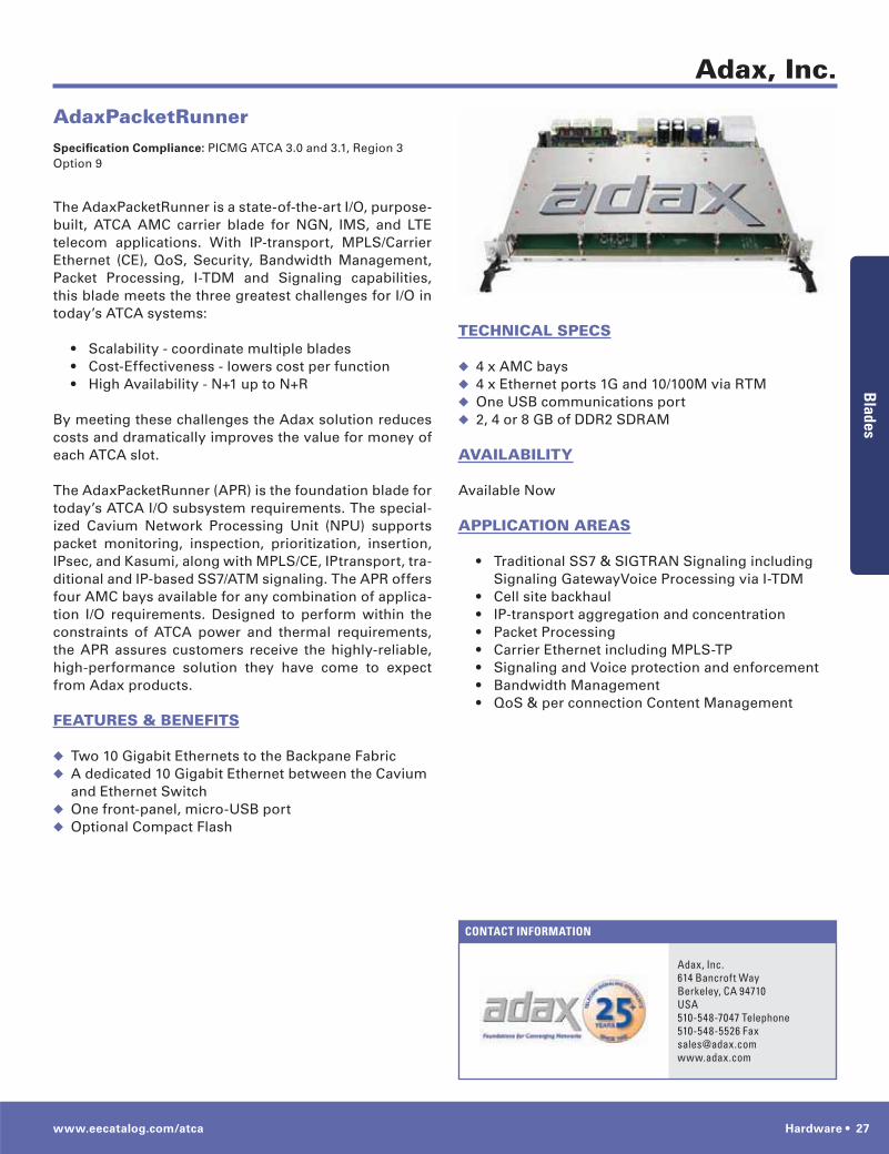
www.eecatalog.com/atca Hardware • 27
CONTACT INFORMATION
Adax, Inc.
Adax, Inc.614 Bancroft WayBerkeley, CA 94710USA510-548-7047 Telephone510-548-5526 [email protected]
TECHNICAL SPECS
4 x AMC bays 4 x Ethernet ports 1G and 10/100M via RTM One USB communications port 2, 4 or 8 GB of DDR2 SDRAM
AVAILABILITY
Available Now
APPLICATION AREAS
• Traditional SS7 & SIGTRAN Signaling including Signaling GatewayVoice Processing via I-TDM
• Cell site backhaul • IP-transport aggregation and concentration • Packet Processing • Carrier Ethernet including MPLS-TP • Signaling and Voice protection and enforcement • Bandwidth Management • QoS & per connection Content Management
AdaxPacketRunnerSpecification Compliance: PICMG ATCA 3.0 and 3.1, Region 3 Option 9
The AdaxPacketRunner is a state-of-the-art I/O, purpose-built, ATCA AMC carrier blade for NGN, IMS, and LTE telecom applications. With IP-transport, MPLS/Carrier Ethernet (CE), QoS, Security, Bandwidth Management, Packet Processing, I-TDM and Signaling capabilities, this blade meets the three greatest challenges for I/O in today’s ATCA systems:
• Scalability - coordinate multiple blades • Cost-Effectiveness - lowers cost per function • High Availability - N+1 up to N+R
By meeting these challenges the Adax solution reduces costs and dramatically improves the value for money of each ATCA slot.
The AdaxPacketRunner (APR) is the foundation blade for today’s ATCA I/O subsystem requirements. The special-ized Cavium Network Processing Unit (NPU) supports packet monitoring, inspection, prioritization, insertion, IPsec, and Kasumi, along with MPLS/CE, IPtransport, tra-ditional and IP-based SS7/ATM signaling. The APR offers four AMC bays available for any combination of applica-tion I/O requirements. Designed to perform within the constraints of ATCA power and thermal requirements, the APR assures customers receive the highly-reliable, high-performance solution they have come to expect from Adax products.
FEATURES & BENEFITS
Two 10 Gigabit Ethernets to the Backpane Fabric A dedicated 10 Gigabit Ethernet between the Cavium and Ethernet Switch
One front-panel, micro-USB port Optional Compact Flash
BladesB
lade
s

28 • Hardware Engineers’ Guide to ATCA® & MicroTCA Technologies 2010
CONTACT INFORMATION
CONTACT INFORMATION
Emerson Network Power
Emerson Network Power2900 S. Diablo Way, Suite 190Tempe, AZ 85282USA1 602 438 5720 Telephone1 800 759 1107 Toll [email protected]/EmbeddedComputing
FEATURES
Dual four- or six-core Intel Xeon processors E5620 or E5645 (ATCA-7365-CE)
Dual six-core Intel Xeon processor L5638 @ 2.0 GHz (ATCA-7365)
Up to 96GB main memory Hot-swappable hard disk with flexible choice of stor-age options
ATCA-7365 & ATCA-7365-CE Processor BladesCompatible Operating Systems: Red Hat RHEL 5.5, Wind River PNE LE 3.0, Microsoft Windows Server 2008, VMware ESX/ESXi
Specification Compliance: PICMG 3.0, 3.1
The ATCA-7365-CE has two four- or six-core Intel® Xeon® processors and offers scalable, high-performance com-puting power for data processing applications requiring powerful server-class processing performance, flexible mass storage and network options. The ATCA-7365 NEBS processor blade has two 6-core Intel Xeon proces-sors to help drive successful implementation of next-gen telecom networks and communication infrastructures.
The PICMG 3.1 compliant fabric interface on both blades provides 10GbE capabilities for applications needing higher network throughput in the backplane.
Both blades offer best-in-class memory support of up to 96GB! Multiple network and storage I/O interfaces allow the integration into different network infrastructures. Main memory and mass storage options can be flexibly configured to fit the application’s needs.
BladesB
lade
s
CONTACT INFORMATION
Emerson Network Power
Emerson Network Power2900 S. Diablo Way, Suite 190Tempe, AZ 85282USA1 602 438 5720 Telephone1 800 759 1107 Toll [email protected]/EmbeddedComputing
FEATURES
Six-core Intel Xeon processor L5638 @ 2.0 GHz Up to 48GB main memory One mid-size AMC site On-board SATA drive option Hot-swappable hard disk with flexible choice of storage options via RTM
ATCA-7367 High Performance Processor BladeCompatible Operating Systems: Red Hat RHEL 5.5, Wind River PNE LE 3.0, Microsoft Windows Server 2008, VMware ESX/ESXi
Specification Compliance: PICMG 3.0, IPMI 1.5, AMC.0, AMC.1, AMC.2, AMC.3
The ATCA-7367 processor blade, featuring a six-core Intel® Xeon® processor L5638 and an AMC site, enables the highest compute performance and I/O functionality in an ATCA form factor. The AMC site provides flexible con-nectivity for networking, storage, telecom clocking and I/O. The PICMG® 3.1 compliant fabric interface provides 10 Gigabit Ethernet (10Gbps) capabilities for applications requiring higher network throughput in the backplane.
Multiple network and storage I/O interfaces allow the integration into different network infrastructures such as telecommunication central offices and network data centers. Main memory configuration and mass storage options can be flexibly configured.

www.eecatalog.com/atca Hardware • 29
CONTACT INFORMATION
CONTACT INFORMATION
BladesB
lade
s
Emerson Network Power
Emerson Network Power2900 S. Diablo Way, Suite 190Tempe, AZ 85282USA1 602 438 5720 Telephone1 800 759 1107 Toll [email protected]/EmbeddedComputing
FEATURES
PICMG® 3.0 compliant base interface switch PICMG 3.1, Option 1, 9 fabric interface switch (1G/10G)
PICMG 3.1, R2 (4x 10Base-KR) fabric interface (40G) Single AMC site Optional SATA HDD and Telecom clock functions
ATCA-F140 40G ATCA Switch BladeCompatible Operating Systems: Carrier-grade Linux
Specification Compliance: PICMG 3.0, 3.1, 3.2 R2, AMC.1, AMC.2, AMC.3
The ATCA-F140 is a high performance, high bandwidth 40G switch blade for ATCA platforms that is ideal for bandwidth-intensive telecom applications. With several ATCA functions combined into a single blade, it allows end users to maximize billable slots with revenue-gener-ating application blades.
Optional functions include telecom clock generation and distribution, SATA based hard drives devices and an AMC site for general processing and packet processing functions.
A fully integrated and verified software package is avail-able that includes carrier-grade Linux OS, all required device drivers and SRstackware switch software. The ATCA-F140 is designed for NEBS/ETSI compliance.
AdvancedTCA® and MicroTCA®Resource Catalog ONLINE
Explore...Directory of leading ATCA, MicroTCA
and AdvancedMC Solutions
Top Stories and News
White Papers
Expert Opinions (Blogs)
Exclusive Videos
Valuable Articles
Ask the Experts
Sign up for the quarterly AdvancedTCA & MicroTCA E Product Alert
www.eecatalog.com/atca

30 • Hardware Engineers’ Guide to ATCA® & MicroTCA Technologies 2010
CONTACT INFORMATION
Pinnacle Data Systems, Inc.
Pinnacle Data Systems, Inc.6600 Port RoadGroveport, OH 43125USA+1 (614) 748-1150 Telephone+1 (614) 748-1209 [email protected]
TECHNICAL SPECS
AMD Opteron processors supported include power efficient embedded dual- and quad-core models up to 2.4GHz
4 DIMM sockets enable up to 32GB DDR2 ECC Memory
Front Panel Interfaces - 2 x GbE ports, 2 x USB 2.0 Backplane Interfaces - 2 x GbE Base and 2 x GbE Fabric, supports dual-star backplane topology
AMC slot for HDD or I/O expansion, plus optional onboard Compact Flash
AVAILABILITY
Now
APPLICATION AREAS
PDSi’s ATCA-F1 blade is targeted at the following indus-tries and applications requiring the ultimate in computing capability and dependability:
Military/Aerospace/Defense • Avionics and ship-board platforms • Communications systems • Real-time Intelligence systems
Telecom • Core applications • Edge applications • Access applications
ATCA-F1 Dual AMD Socket F AdvancedTCA BladeCompatible Operating Systems: Linux (SuSe, RHEL), Windows (Server 2003, XP), Solaris x86, VMWare ESX Server 3.5 and 4.0
Specification Compliance: PICMG ATCA3.0 R2
PDSi’s Dual AMD Socket F AdvancedTCA® Blade (ATCA-F1) is an incredibly fast x86 server available in the ATCA form factor. Now offered with a full 32GB of memory and two benchmark-setting AMD “Shanghai” quad-core CPUs, this blade provides the extra level of computing horsepower and built-in virtualization support demanded by the next generation of COTS integrated architectures. With its robust design, the ATCA-F1 blade has been thoroughly tested and successfully deployed in critical systems including military applications.
The ATCA-F1 features a standard Zone 3 interface for connection to PDSi’s ATCA-RT01 rear transition module (RTM), which adds SAS storage, video, Ethernet and USB resources. The ATCA-F1 and ATCA-RT01 RTM combina-tion has been validated and is hardware-compliant with the VMWare® ESX Server virtualization platform.
Other on-blade features include a Compact Flash site and an AdvancedMC™slot for additional I/O or further storage expansion. The blade includes Pigeon Point’s module management for IPMI support and board-level health monitoring.
PDSi gives telecom, aerospace, and military OEMs the ability to deploy configurable, scalable, high-reliability ATCA solu-tions using this powerful compute blade based on AMD’s latest Quad Core processor technology. Extended availability from PDSi is assured as key components are supported by embedded roadmaps. PDSi can also provide customization, turnkey integration and support of ATCA systems, as well as extended warranty and repair services.
FEATURES & BENEFITS
Ultra - high performance AdvancedTCA server blade features leading-edge AMD64 technology
Supports two Quad-core “Shanghai” or Dual-core AMD Opteron™ processors with HyperTransport™ technology
Zone 3 interface enables I/O and storage expansion via PDSi’s ATCA-RT01 RTM
Certified with VMWare ESX Server 3.5 and 4.0 when used with PDSi’s ATCA-RT01 RTM
Proven, third generation design
BladesB
lade
s

www.eecatalog.com/atca Hardware • 31
CONTACT INFORMATION
Pinnacle Data Systems, Inc.
Pinnacle Data Systems, Inc.6600 Port RoadGroveport, OH 43125+1 (614) 748-1150 Telephone+1 (614) 748-1209 [email protected]
TECHNICAL SPECS
VGA Video supports resolutions up to 1600 x 1200 Onboard 2.5 inch serviceable SAS HDD provides up to 146 GB storage. External SAS connector for expansion.
2 - 10/100/1000 BaseT Ethernet ports (from front blade)
2 - USB 2.0 ports 1 - RS232 serial port (from front blade)
AVAILABILITY
Now
APPLICATION AREAS
Military, Aerospace, Telco, Enterprise
ATCA-RT01 AdvancedTCA RTM with Video and StorageCompatible Operating Systems: Windows (Server, 2003, XP), Linux (SuSe, RHEL), Solaris 10 x86 and SPARC, VMware ESX Server 3.5 and 4.0
Specification Compliance: PICMG ATCA3.0
PDSI’s Video + Storage ATCA Rear Transition Module (ATCA-RT01) provides high reliability SAS storage, VGA video output and additional I/O functionality for AdvancedTCA® systems using x86 processor blades from PDSi or Sun Microsystems. In addition, it also oper-ates with Sun’s UltraSPARC® T2-based Netra™ CP3260 blade. For systems requiring a mix of these compute blades, the ATCA-RT01 can provide a “universal RTM” solution.
The ATCA-RT01 complies with PICMG ATCA 3.0 speci-fications for seamless and dependable operation in critical applications. It features a 2.5 inch SAS HDD for local storage as well as front-panel access to the onboard SAS controller for connection to secondary or redun-dant storage arrays. Additional ports include VGA video output and USB I/O for convenient local monitoring or configuration of applications. Serial and Ethernet ports are also routed from the front blade so that all required I/O can be rear-accessible. The RTM includes Pigeon Point’s module management.
Telecom, aerospace, and military OEMs will appreciate the flexibility this advanced RTM brings to their systems. Extended availability from PDSi is assured. PDSi can also provide customization, turnkey integration and sup-port of ATCA systems, as well as extended warranty and repair services.
FEATURES & BENEFITS
RTM offers VGA video and SAS storage resources for selected ATCA applications
x86 blade compatibility: PDSi ATCA-F1 and SUN Netra CP3220
SPARC blade compatibility: SUN Netra CP3260 Robust design for military, aerospace, telco and enterprise applications
Certified with VMWare ESX Server 3.5 and 4.0 when used with PDSi’s ATCA-F1 blade
BladesB
lade
s

32 • Hardware Engineers’ Guide to ATCA® & MicroTCA Technologies 2010
CONTACT INFORMATION
Adax, Inc.
Adax, Inc.614 Bancroft WayBerkeley, CA 94710USA510-548-7047 Telephone510-548-5526 [email protected]
• SSSAR/SSTED/SSADT, ITU-T I.366.1 • HSL over AAL5, Telcordia GR-2878-Core
AMC System Interconnect • PCI Express One x1 Express Interface • Gigabit Ethernet Four Gigabit Ethernet links on
AMC ports 0-1 and 8-9
Front Panel LEDs • AMC.0 IPMI (2x) • Hot Swap (Adjacent to Latch) • Per Port Status (4x) • Board Status/User Programmable
Interfaces • Four OC-3/STM-1 • Two OC-12/STM-4 • Support for single mode fiber and multi-mode
fiber (ITU G.957)
AVAILABILITY
Available Now
APPLICATION AREAS
• 3G RNC, MSC, SGSN, and Node B • Voice over Packet • Video Streaming • Broadband Networks • ATM to IP Gateways • Femtocell Access Controller
ATM4-AMCCompatible Operating Systems: Linux and Solaris as standard. Other OS support on request.
Specification Compliance: PICMG AMC.0 R2.0, AMC.1, AMC.2, IPMI V1.5
The ATM4-AMC card is a high performance AdvancedTCA Mezzanine Controller designed for use in all aspects of telecommunications networks. The ATM4 includes sup-port for ATM host termination, switching and L2/L3/L4 or higher interworking between Gigabit Ethernet interfaces and ATM interfaces. With support for AAL2 and AAL5, the ATM4 has the ability for real-time voice and video over AAL2, as well as signaling and IP over AAL5 in 3G networks. The ATM4 is ideal for demanding carrier applications in Wireless 2G, 3G, IMS, Internet Access, Fixed/Mobile Con-vergence and Next Generation Networks.
The ATM4 enables development flexibility in building Next Generation infrastructure and can be configured in many ways depending on customer specifications and preferred architecture. In addition, the AMC form factor provides enhanced performance and reliability.
One or two ATM4’s, integrated with an ATCA/SBC, can be configured as a signaling blade, housing complete ATM/IP gateways and offering a high density, single slot, market leading solution. Alternatively, up to four AMC modules can be mounted with an Advanced TCA carrier card for a high density ATCA signaling blade. This flexibility enables integrators to satisfy a wide range of requirements with a single core architecture, saving development time and allowing customers to integrate their solutions ahead of the competition.
FEATURES & BENEFITS
Multi-Purpose I/O board for 3GPP/IMS Wireless Networks
Four OC-3/STM-1 or Two OC-12/STM-4 ATM AAL2 & AAL5 on a single trunk On-board IP to AAL2 & IP to AAL5 Interworking AMC form factor for ATCA & MicroTCA Platforms
TECHNICAL SPECS
Wintegra WinPath2 Network Processor Protocol Support
• ATM AAL2, ITU-T I.363.2 • ATM AAL5, ITU-T I.363.5 • SSCOP, Q.2110 • SSCF NNI, Q2140 • SSCF at UNI per Q.2130 • SSCS Layer Management Q.2144
Boards / B
oard AccessoriesB
oard
s / B
oard
Acc
esso
ries

www.eecatalog.com/atca Hardware • 33
CONTACT INFORMATION
Adax, Inc.
Adax, Inc.614 Bancroft WayBerkeley, CA 94710USA510-548-7047 Telephone510-548-5526 [email protected]
• High impedance ports in accordance with G.772 • Up to 2 10/100/1000 BaseT Ethernet interfaces per
PCI, PCIe, EM card • Up to 2 1000 BaseX Ethernet interfaces per AMC card
Power RequirementsPMC/LPe
• 6-10 watts typical-maximum power consumptionPCI/PCIe/EM
• 7-12 watts typical-maximum power consumption AMC • 8-14 watts typical-maximum power consumption
AMC System InterconnectPCI Express: One x4 PCI Express Interface.AMC fat pipes region port 4-7 (root complex)Gigabit Ethernet: Two Gigabit Ethernet 1000Base-BXZ (SerDes) ports AMC common options region port 0-1.
AVAILABILITY
Available Now
APPLICATION AREAS
• Signaling Gateways • Media Gateway Controllers • SGSN, GGSN, MSC, HLR, VLR, and BSS Nodes • VAS Applications such as SMS, Roaming and Billing • Test and Measurement applications • Simulation and Monitoring Systems
HDC3Compatible Operating Systems: Linux, MontaVista CGE, Solaris X.86 & SPARC. Other OS support on request.
Specification Compliance: PICMG AMC.0 R2.0, AMC.1, AMC.2, AMC.3, IPMI V1.5
The HDC3 is the latest generation of the highly successful Adax SS7 controller and is the first to offer up to 8 T1, E1 or J1 trunks per card. Specifically designed to meet the demands of wireline, wireless and NGN convergence platforms, the HDC3 excels at SS7 and provides a high density high perfor-mance solution for narrowband signaling applications.
Delivering up to 248 LSL MTP2 links or 8 HSLs (Q.703 AnnexA and ATM AAL5) per card, the HDC3 provides one of the highest densities on the market today, making it ideal for demanding telecommunications applications with high capacity and throughput requirements. The on board processor performs many thousands of transactions per second, with minimal load on the host, maximizing the performance of the applications and reducing system costs without compromising reliability.
The HDC3 is available in PMC, AMC, PCI/X and PCIe (including the new ExpressModule) form factors, all of which share a common software driver and have a consistent API for appli-cation portability. This makes the HDC3 card a highly flexible, scalable and portable signaling solution for all system archi-tectures that maximizes protection of investment.
FEATURES & BENEFITS
8 software selectable trunks of full E1, T1, or J1 per card PMC, AMC, PCI/X and PCIe (Full height and Low-Profile and ExpressModule) board formats
Up to 248 LSL MTP2 links per card with high line utilization and 8 MTP2 HSLs
Single HDC3 driver supports PCI/PCI-X, PCIe, PMC and AMC form factors, so applications run unchanged across all architectures
Support for up to 128 channels of Frame Relay or a combination of 248 channels of HDLC, X.25, LAPB/D/F/V5 protocols
TECHNICAL SPECS
Interfaces • T1: ANSI T1.102, T1.403, AT&T TR62-411, TR-TSY-
000170 • E1: ITU Structured G.703; G.704 and G.705 including
CRC4, ETSI TBR 12 and 13 • J1: ITU TTC JT-G.703, JT-G.704 • 8 E1/T1/J1 interfaces (software selectable) • Jitter and Wander in accordance with ITU-T G.823
Boards / B
oard AccessoriesB
oard
s / B
oard
Acc
esso
ries

34 • Hardware Engineers’ Guide to ATCA® & MicroTCA Technologies 2010
CONTACT INFORMATION
Adax, Inc.
Adax, Inc.614 Bancroft WayBerkeley, CA 94710USA510-548-7047 Telephone510-548-5526 [email protected]
Ethernet Controller - Dual Gigabit Ethernet Controller Intel 82571EB - PCIe 4-lane interface to Cavium Processor - 2 1000Base-BX (Serdes) interfaces to AMC connector - Serial Over LAN via SMB
Memory - 1, 2 or 4 Gigabyte DDR2 Memory support with ECC
800MHz data rate (2GB standard) - 128MB FLASH Memory - USB Flash Disk up to 4 GB
Interfaces - 2x RS232 via micro-interface - 1x micro USB
AVAILABILITY
Available Now
APPLICATION AREAS
• Cell site backhaul • Femtocells / WiMAX / UMA / VoLTE ACs • MGW, MGC, RNC, SBC, MME • IP-transport aggregation and concentration • Routing and Security acceleration • Signaling and voice protection and enforcement • SIP & Diameter Protocols • RTP • IPTV, Video • Traditional SS7 & SIGTRAN Signaling including
Signaling Gateway • Voice Processing via I-TDM
PacketAMC (PktAMC)Specification Compliance: PICMG AMC.0 R2.0, AMC.1 R2.0, AMC.2, IEEE 802.3, IPMI V1.5
With a Cavium Octeon Plus 56XX processor and 4GbE interfaces, frontend processing of the Layer 2 protocols can reside on the Adax PacketAMC (PktAMC) providing hardware acceleration of the basic Layer 2 switching. At the same time the advanced Layer 2 Switching and Routing, MPLS-TP, PBB-TE, QoS, High Availability and Management can take place on the AdaxPacketRunner.
At a high level, the PktAMC is applicable in the broadest range of ATCA legacy and emerging network elements found in today’s networks such as MSCs, MGs, HLRs, x-CSCFs, HSSs, etc. The combination of the PktAMC and the APR delivers a ‘subsystem’ for LTE-SAE, IMS, VoLTE, UMA & Femtocell applications.
The PacketAMC together with the AdaxPacketRunner ATCA carrier blade provides the high performance delivery of control and data plane services from one tightly coupled resource. Contention on the chassis backplane is removed, allowing multiple IP flows to be processed on the APR. Pro-cessed packets are then available for immediate transport to system application servers or the IP network.
FEATURES & BENEFITS
I/O Subsystem for LTE-SAE High Performance hardware acceleration with Cavium Octeon Plus 56XX
High Performance Application Acceleration including: - Packet I/O processing - QoS Queuing & scheduling - IPsec, SSL, SRTP, WLAN and 3G/UMB/LTE security
Carrier Ethernet - MPLS-TP - PBB-TE - Traffic & Bandwidth Management
TECHNICAL SPECS
Processor - Cavium Octeon Plus CN56XX, up to 12 cores 800 MHz
Configurations: • Front Panel configurations: - 4x SFP GbE - 1x SFP+ 10GbE (Option) • SW configurable FAT pipe region Interface • 10GbE; Quad GbE; PCIe x4 or x8
Boards / B
oard AccessoriesB
oard
s / B
oard
Acc
esso
ries

www.eecatalog.com/atca Hardware • 35
CONTACT INFORMATION
Interphase
Interphase2901 N. Dallas Pky, Suite 200Plano, TX 75093USA+1 214-654-5000 Telephone800-327-8638 Toll [email protected]
Front Panel: • 1 or 2 SFP receptacles for CPRI 4.1 • SMB micro-coaxial for GPS antenna/1PPS I/O
signal input/output • 1 or 2 10/100/1000 Ethernet ports
AMC Interfaces: • Gigtabit Ethernet: AMC.2 Type E2, ports 0, 1 GE
(shared with the front panel RJ45s) • PCI Express: AMC.1 Type 4 PCIe on ports 4-7 • Serial Rapid IO: AMC.4 Type 4 sRIO on ports 4-7
Memory: • 512MB DDR3 SDRAM Expandable to 1GB with
optional ECC • 64MB Boot Flash • 1 to 16GB Storage Flash
Form Factor: AMC.0 R2.0 AdvancedMC – Mid Size or Full Size, or to custom spec
Power Consumption: 26W Typical / 36W Max GPS Receiver onboard (optional) Precision clock sourcing on board (optional)
APPLICATION AREAS
• Private applications such as rapidly deployable networks, closed enterprise usage, and machine-to-machine
• Integration into remote radio heads • Public carrier macrocell, microcell, picocell, and
enterprise femtocell basestations
iSPAN 36701 Wireless Basestation AMCCompatible Operating Systems: Linux, VxWorks
Specification Compliance: LTE-FDD, LTE-TDD, WiMAX, W-CDMA, TD-SCDMA
The iSPAN® 36701 LTE Basestation on a Card is an appli-cation-ready, small form factor, customizable basestation module based on the innovative Mindspeed Transcede™ 4020 SoC. The module includes the basestation control, baseband PHY, radio interface, and pre-integrated fully compliant LTE (PHY/L2/L3) protocol layers, making it ready to integrate with a radio and applications software for quick time-to-market eNodeB microcell, picocell, or enterprise femtocell basestations. Mix of programmable DSP and H/W acceleration allows for DSP headroom for additional customer feature development.
The iSPAN 36701 is designed as an entry point for the development of next generation wireless basestations. Interphase can adapt or extend this solution to meet your needs in AMC or in any other form factor required.
FEATURES & BENEFITS
Compact multi-capable SOC technology simplifies basestation design and reduces system latency
Modular hardware/software/API pre-integration enables equipment manufacturers to focus on application and value-add features, accelerating the development cycle
Reduces service provider CAPEX and OPEX with small basestation footprint and significantly reduced basestation cooling and power requirements
TECHNICAL SPECS
Processor: Mindspeed Transcede 4020 SoC • 6 ARM Cortex A9 (RISC) Processor Cores @ 750
MHz (9000 DMIPS) • Option to use T4000 @ 600 MHz • 10 CEVA DSP Cores (24 GMAC/s) • FEC Processor • 10 Application Processors for FFT (6000 MIPS / 24
GMAC/s) • 2 Security Coprocessors
Boards / S
mallform
FactorBoa
rds
/ Sm
allf
orm
Fac
tor

36 • Hardware Engineers’ Guide to ATCA® & MicroTCA Technologies 2010
CONTACT INFORMATION
Boards / S
mallform
FactorBoa
rds
/ Sm
allf
orm
Fac
tor
Zero Time Search provides a fast way to search large traces for specific protocol terms.
Config space can be displayed in its entirety so that driver registers can be verified.
TECHNICAL SPECS
Analyzer Lanes supported: X1,x2,x4,x8,x16 Speeds: 2.5GT/s, 5GT/s and 8GTs Probes/Interposers: active and passive PCIe slot,
XMC, AMC, express card, express module, minicard, MidBus, multi-lead, external PCIe cable and others.
Form factor: Card, Chassis Exerciser
Lanes supported: X1,x2,x4,x8,x16 Speeds: 2.5GT/s, 5GT/s, 8GT/s Emulation: root complex and endpoint emulation
Protocol Test Card Speeds: 2.5GT/s and 5GT/s operation Tests: Add-in-card test BIOS Platform Test Single Root IO Virtualization Test
APPLICATION AREAS
Mezzanine Boards, Add-in Cards, Host Carrier Systems, System Boards, Chips
LeCroy’s PCI Express® Protocol Analysis and Test Tools
Compatible Operating Systems: Windows XP/Vista
Specification Compliance: PCI Express Standards: 1.1, 2.0, and 3.0
Whether you are a test engineer or firmware developer, LeCroy’s Protocol Analyzers will help you quickly iden-tify, troubleshoot and solve all your protocol problems. LeCroy works closely with industry standards groups such as the PCI-SIG®, PICMG, VITA and the Intel Embedded Communication Alliance to help developers rapidly bring to market high performance and reliable PCI Express pro-tocol test solutions.
LeCroy’s products include a wide range of probe connec-tions to support XMC, AMC, ATCA, microTCA, Express Card, MiniCard, Express Module, HP Blade Server Mod-ules, MidBus connectors and flexible mult-lead probes for PCIe® 1.0a, 1.1(“Gen1” at 2.5GT/s) , PCIe 2.0(“Gen 2” at 5 GT/s) and PCIe 3.0(“Gen 3” at 8 GT/s).
The high performance SummitTM T3-16 Protocol Analyzer features the new PCIe virtualization extensions fo SR-IOV and MR-IOV and in-band logic analysis.
LeCroy offers a complete range of protocol test solutions, including analyzers, exercisers, protocol test cards, and physical layer testing tools that are certified by the PCI-SIG for ensuring compliance and compatibility with PCI Express specifications, including PCIe 2.0.
FEATURES & BENEFITS
One button protocol error check. Lists all protocol errors found in a trace. Great starting point for beginning a debug session.
Flow control screen that quickly shows credit balances for root complex and endpoint performance bottlenecks. Easily find out why your add-in card is underperforming on its benchmarks.
LTSSM state view screen that accurately shows power state transitions with hyperlinks to drill down to more detail. Helps identify issues when endpoints go into and out of low power states.
Full power management state tracking with LeCroy’s Interposer technology. Prevents loosing the trace when the system goes into electrical idle.
LeCroy’s Data View shows only the necessary protocol handshaking ack/naks so you don’t have to be a protocol expert to understand if root complexes and endpoints are communicating properly.
Real Time Statistics puts the analyzer into a monitoring mode showing rates for any user term chosen. Good for showing performance and bus utilization of the DUT.
LeCroy Corporation3385 Scott Blvd.Santa Clara, CA, 95054USA1 800 909-7211 Toll Free1 408 727-6622 [email protected]://www.lecroy.com
LeCroy Corporation

www.eecatalog.com/atca Hardware • 37
CONTACT INFORMATION
Scan Engineering Telecom
Scan Engineering Telecom GmbHElisabethstrasse, 91Munich, 80797Germany+49 89 5908 2347 Telephone+49 89 5908 1200 [email protected]
AVAILABILITY
now
APPLICATION AREAS
Telecom – Edge applications, WiMAX and LTE base sta-tions
Industrial – Control&Management systems, Data acqui-sition systems
Medical – Imaging, X-Ray, Ultrasound
Instrumentation – Test & Measurement systems
Aerospace – Avionics and ship-board platforms, Com-munication systems
SMCH-102 Cost-effective MCH for MicroTCA systemsSpecification Compliance: MTCA.0 R1.0
Scan Engineering Telecom MCH (Management Carrier Hub) SMCH-102 is a perfect solution for cost-sensitive applications based on MicroTCA ecosystem.
SMCH-102 provides without switch management and complex control software. Compare to rich-featured MCH SMCH-100 it has only one MCH tongue. SMCH-102 provides two Gigabit Ethernet uplinks (through RJ-45 connectors) on the front panel and one serial interface to access the management controller (MCMC). On the edge connector there are 12 x GbE channels for AMC mod-ules. In addition SMCH-102 supports some features from SMCH-100 like supporting two MCHs in one system, flash for failover and microcode rollback for both IPMI and GbE switch, RMCP support, Real Time Clock.
SMCH-102 gives OEMs in an effective solution for building cost-sensitive application. Scan Engineering Telecom can also provide customization, turnkey integration and support to ensure that OEMs can focus where they prefer to add their own unique value.
FEATURES & BENEFITS
Cost-optimize solution for MicroTCA systems Capability for using two MCHs in one system For cost-sensitive applications in telecom, industrial, medical test & measurement and aerospace industries
Customization welcomed
TECHNICAL SPECS
System management and Ethernet switching for up to 12 AMC modules via unmanaged Ethernet switch
Supports HPM.1, IPMI v1.5 and RMCP interface Fash for failover and rollback for both IPMI system and GbE switch
Capability for using two MCHs in one MicroTCA system
2 x GbE uplinks and 1 x serial on front panel
Boards / S
mallform
FactorBoa
rds
/ Sm
allf
orm
Fac
tor

38 • Hardware Engineers’ Guide to ATCA® & MicroTCA Technologies 2010
CONTACT INFORMATION
Scan Engineering Telecom
Scan Engineering Telecom GmbHElisabethstrasse, 91Munich, 80797Germany+49 89 5908 2347 Telephone+49 89 5908 1200 [email protected]
TECHNICAL SPECS
Four SSD sub-systems operating via SATAII channel, each with its own power supply
1024GB (1TB) for data storage Data read/write rates up to 270MB/s 2 x SATAII channels and 1 x PCIe x1 bus Supports different RAID options
AVAILABILITY
now
APPLICATION AREAS
Telecom – Edge applications, next-generation conver-gent media gateways, media servers, messaging servers, storage systems
Datacom/Enterprise computing – network security/fire-wall appliances, storage systems, gateways
Industrial – storage subsystems, transport applications
Instrumentation – test & measurement systems
Aerospace – Avionics and ship-board platforms, Com-munication systems, Real-Time Intelligence systems, Simulators
SAMC-203 High-performance AdvancedMC storage moduleCompatible Operating Systems: Windows, Linux, FreeBSD
Specification Compliance: PICMG AMC.0 R2.0
Scan Engineering Telecom presents second generation of its SAMC-203, high-efficient storage module with RAID support implemented as a AdvancedMC™ Module for use in AdvancedTCA® and MicroTCA™ systems.
Designed around RAID controller and based on Flash memory (MLC or SLC) SAMC-203 have maximum capacity of 1024 GB (1TB) for data storage, data read/write rates up to 270MB/s and provides excep-tional performance in the convenient and versatile AdvancedMC™ form factor.
On-board RAID controller support different RAID modes including but not limited to RAID0, RAID10, Concatenation SAFE30 and SAFE50. SAMC-203 has two SATAII channels for systems without PCI Express switching logic inside MCH, required channel can be selected manually/automatically and SATAII-PCIe bridge for systems with PCI Express interconnection.
For high reliability each of storage subsystems has its own power supply as well as power supply for the entire module.
SAMC-203 gives OEMs in a broad range of industries a higher performance and cost effective solution. Scan Engineering Telecom can also provide customization, turnkey integration and support to ensure that OEMs can focus where they prefer to add their own unique value.
FEATURES & BENEFITS
High-performance AdvancedMC Storage module Storage capacity up to 1024GB (1TB) SATAII channels and PCI Express bus for operating in any kind of xTCA systems
For OEMs in telecom, datacom, industrial, medical, test & measurement and aerospace industries
Customization welcomed
Boards / S
mallform
FactorBoa
rds
/ Sm
allf
orm
Fac
tor

www.eecatalog.com/atca Hardware • 39
CONTACT INFORMATION
Scan Engineering Telecom
Scan Engineering Telecom GmbHElisabethstrasse, 91Munich, 80797Germany+49 89 5908 2347 Telephone+49 89 5908 1200 [email protected]
Up to 128 Gbyte on-board SSD drive via internal SATA channel
PCI Express x8 lane or two PCI Express x4/x1 lanes, two SATA/SAS channels and two Gigabit Ethernet channels via AMC connector
Front panel interfaces – 2 x USB 2.0, 1 x Serial
AVAILABILITY
now
APPLICATION AREAS
Telecom – Edge applications, next-generation convergent media gateways, media servers, messaging servers, ses-sion border controllers, WiMAX and LTE base stations
Datacom/Enterprise computing – Routers/gateways, network security/firewall appliances, switches
Industrial – Embedded controllers, co-processor appli-cations
Medical – Imaging, X-Ray, Ultrasound
Instrumentation – Test & Measurement systems
Aerospace – Avionics and ship-board platforms, Com-munication systems, Real-Time Intelligence systems, Simulators
SAMC-504 Quad-Core AdvancedMC Processor moduleCompatible Operating Systems: Windows, Linux, FreeBSD
Specification Compliance: PICMG AMC.0 R2.0
The Scan Engineering Telecom’s SAMC-504 is a Intel®-based AdvancedMC™ Processor Module.
SAMC-504 is a high performance computing module for use in AdvancedTCA® and MicroTCA™ systems. Designed around Intel’s x86-based Core2™ Quad pro-cessors, it provides exceptional computing power and performance in the convenient and versatile AdvancedMC™ form factor.
The SAMC-504 complies with the most current PICMG® specifications for operation in ATCA and MicroTCA applications. This module supports sub-specifications to insure compatibility with the broad set of interface options presented by AMC carriers – including SAS/SATA, Ethernet and PCI-Express. It also features an onboard SATA SSD disk drive for extend typical application areas.SAMC-504 gives OEMs in a broad range of industries a higher performance and cost effective solution. Scan Engineering Telecom can also provide customization, turnkey integration and support to ensure that OEMs can focus where they prefer to add their own unique value.
SAMC-504 gives OEMs in a broad range of industries a higher performance and cost effective solution. Scan Engineering Telecom can also provide customization, turnkey integration and support to ensure that OEMs can focus where they prefer to add their own unique value.
FEATURES & BENEFITS
High-performance AdvancedMC processor module offers new way in performance-per-watt
High-performance Intel Core2 Quad architecture doubles the performance of a typical dual-core solution, demonstrates maximum power efficiency, provides excellent computing power and supports up to 4 simultaneous computing threads
A very cost-effective computing platform for AdvancedTCA and MicroTCA solutions
For OEMs in telecom, datacom, industrial, medical test & measurement and aerospace industries
Customization welcomed
TECHNICAL SPECS
Intel Core2 Quad CPU running at 2.20GHz Up to 4 Gbyte DDR2 memory with ECC support run-ning at 400MHz
Boards / S
mallform
FactorBoa
rds
/ Sm
allf
orm
Fac
tor
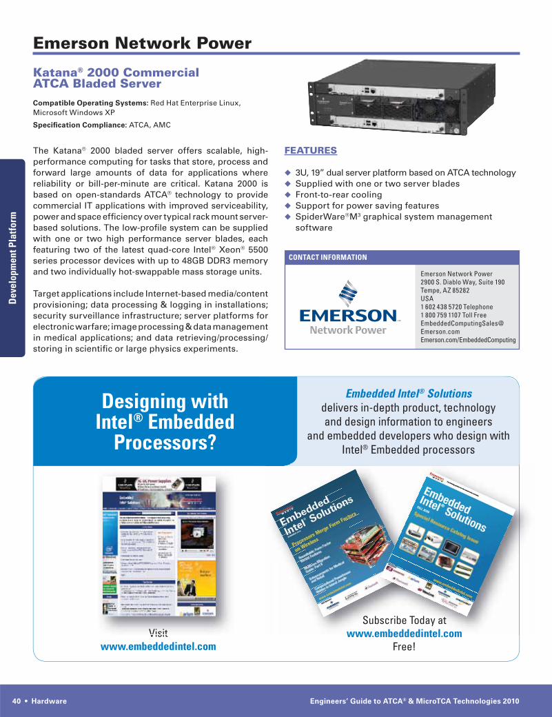
40 • Hardware Engineers’ Guide to ATCA® & MicroTCA Technologies 2010
CONTACT INFORMATION
CONTACT INFORMATION
Emerson Network Power
Emerson Network Power2900 S. Diablo Way, Suite 190Tempe, AZ 85282USA1 602 438 5720 Telephone1 800 759 1107 Toll [email protected]/EmbeddedComputing
FEATURES
3U, 19” dual server platform based on ATCA technologySupplied with one or two server bladesFront-to-rear coolingSupport for power saving featuresSpiderWare®M3 graphical system management software
Katana® 2000 Commercial ATCA Bladed ServerCompatible Operating Systems: Red Hat Enterprise Linux, Microsoft Windows XP
Specification Compliance: ATCA, AMC
The Katana® 2000 bladed server offers scalable, high-performance computing for tasks that store, process and forward large amounts of data for applications where reliability or bill-per-minute are critical. Katana 2000 is based on open-standards ATCA® technology to provide commercial IT applications with improved serviceability, power and space efficiency over typical rack mount server-based solutions. The low-profile system can be supplied with one or two high performance server blades, each featuring two of the latest quad-core Intel® Xeon® 5500 series processor devices with up to 48GB DDR3 memory and two individually hot-swappable mass storage units.
Target applications include Internet-based media/content provisioning; data processing & logging in installations; security surveillance infrastructure; server platforms for electronic warfare; image processing & data management in medical applications; and data retrieving/processing/storing in scientific or large physics experiments.
Developm
ent Platform
Dev
elop
men
t Pla
tfor
m
Designing with Intel® Embedded
Processors?
Embedded Intel® Solutions delivers in-depth product, technology and design information to engineers
and embedded developers who design with Intel® Embedded processors
Visitwww.embeddedintel.com
Subscribe Today atwww.embeddedintel.com
Free!Visit
Subwww embeddedin
ay atntel com
bscribe Todaembeddedin

www.eecatalog.com/atca Hardware • 41
CONTACT INFORMATION
Elma Electronic Inc.
Elma Electronic Inc.44350 Grimmer Blvd.Fremont, CA 94538USA510-656-3400 Telephone510-656-3783 [email protected]
TECHNICAL SPECS
2U - 6U horizontal configurations with AC & DC options; 13U vertical configuration (DC only)
Up to 300W slot cooling N+1 redundant power entry modules (PEMs) Optional, redundant shelf manager Designed to meet FCC & NEBS EMC require-ments
AVAILABILITY
Shipping now
APPLICATION AREAS
Edge of the Network; transport and data centers, wire-less/WiFi, wireline, and optical network elements. Ground based mission communications in military deployments.
AdvancedTCA System PlatformsCompatible Operating Systems: Linux, VxWorks, Windows
Specification Compliance: PICMG 3.0
Elma’s ATCA platforms are compliant to PICMG 3.0 and are based on a modular design offering a wide range of chassis configurations. The 2U - 6U horizontal configura-tions support 90 – 235 VAC and 48 VDC inputs; the 13U vertical chassis supports 48 VDC for telco related appli-cations. A choice of backplane fabric topologies (star, dual star, mesh full & replicated) include support of up to 40 Gbs. Elma’s platforms can support up to 300W per slot cooling; each unit is shipped with N+1 redundant power modules; an optional redundant shelf manager is also available.
Elma’s ATCA System Platforms are based on a proven design concept which reduces program risk (time and cost). Typical applications in which Elma’s platforms are ideally suited are: edge core, transport and data center; wireless, wireline, and optical network elements.
Customers take advantage of Elma’s well established partnerships with premier industry suppliers to develop and deploy integrated and pre-configured ATCA systems with processors, storage, switch blades, and other I/O requirements. The company can supply an integrated platform all the way up to the cabinet level. Extensive thermal testing is conducted at the main manufacturing facilities. Elma is also well suited to work with companies considering deploying ATCA based communications systems in the mil/aero space.
FEATURES & BENEFITS
Wide range of chassis configurations based on a modular design enables faster time to market
Proven design concept reduces program risk by offering time and cost savings
Choice of backplane fabric topologies (star, dual star, mesh full & replicated; support for up to 40 Gbs backplane options
Superior thermal performance qualified through extensive in-house testing
EnclosuresEncl
osur
es

42 • Hardware Engineers’ Guide to ATCA® & MicroTCA Technologies 2010
CONTACT INFORMATION
Schroff
Schroff170 Commerce DriveWarwick, RI 02886USA(401) 732-3770 Telephone401) 738-7988 Faxwww.schroff.us
AVAILABILITY
Units in stock for immediate delivery
APPLICATION AREAS
Military, Medical, Security, Test & Measurement, Electronic OEM, Telecom, Enterprise, Industrial and Transportation
MicroTCA Enclosures
Schroff has developed a wide range of small innovative MicroTCA enclosures that will accelerate your time-to-market and balance the performance-to-cost ratio that allow system integrators to deliver an overall solution with a distinct competitive advantage.
The unique mechanical and tested design of Schroff’s card guides, subracks, EMC gasket, and struts allow for maximum flexibility and consistent performance in every application. From this, many products have been developed to meet the enterprise, telecom, mili-tary, industrial and medical markets. Cost effective backplane routing designs and innovative cooling and power management solutions are helping system integrators in all of these markets achieve their cost and performance objectives for next generation equipment. Compliance engineering expertise along with Global manufacturing and support will ensure that your products are released on schedule.
Schroff has been leading the MicroTCA specification development since its conception and provides all the components, hardware, development, production through hardened enclosures that you would require. Contact an Applications Engineer to learn more about how Schroff’s MicroTCA products can help you achieve your Next Generation Systems requirements. Schroff is committed to provide the best engineered and quality enclosure for your specific application.
FEATURES & BENEFITS
Proven MicroTCA hardware, card guides, EMC gasket, subrack assembly
Table-Top and Side-Mount Cube Systems 1U thru 8U rackmount systems with redundant cooling solutions and EMMC on-board
Solutions with fixed AC Power Entry and other power configuration options
Backplane design and manufacturing for lower layer count and high performance. Customization for point-to-point routing for cost and performance optimization
Proof-of-Concept ruggedized AMC hardware and hardened MicroTCA Enclosures, including conduc-tion-cooled ATR
Modular power management schemes for full compliant and options for low featured, cost effective power management.
EnclosuresEncl
osur
es

www.eecatalog.com/atca Hardware • 43
CONTACT INFORMATION
MicroBlade
MicroBlade567 D’Onofrio DriveSuite 150Madison, WI 53719USA(608) 729-5370 Telephone(866) 249-2499 [email protected]
• Dual Ring Option • Provides two fat pipe rings between AMC 2, 4 &
6 and AMC 1, 3 & 5 • Port 2 & 3 SATA /SAS connectivity to the adjacent
slot • Ports 4-7, 8-11, 12-15 and 17-20 fat pipe connectivity
is point to point with support for PCIe, XAUI or SRIO
Cooling Unit: • Excellent thermal profile providing over 100 CFM
of airflow • 4 push-pull fans per CU with each fan rated at 20 CFM • Individually controlled with variable fan speed • Straight through side-to-side cooling • Fully managed, redundant and hot swappable • Air filter removed detection • Mini-USB diagnostic port
Environmental /Regulatory/Compliance: • Standard operating temperature: -5 C to +45 C • Storage temperature: -45 C to +85 C • Shock and vibration: Level DL1, IEC 61587-1 • FCC Part 15, Class A Compliant • EN 55022 • EN 55024 • EIA Compliant • RoHS Compliant • PICMG MicroTCA.0 R1.0
AVAILABILITY
Now
APPLICATION AREAS
Commercial Communications, military communications, telecom, enterprise telecom, wireless telecom, automated test equipment, medical, video demand, security, industrial machine control and other clustered computing applications.
MicroBoxPlus 1USpecification Compliance: PICMG MicroTCA R1.0, RoHS Compliant
MicroBoxPlus 1U offers the performance benefit of MicroTCA in a space-saving horizontal-mounted 1U height. Six AdvancedMC (AMC) slots provide users the flexibility to configure the system for a wide range of applications including telecom, wireless telecom, enterprise communica-tion, security and industrial automation/machine control.
If your applications demand the highest computing per-formance with space and power constraint, MicroBoxPlus 1U is your solution.
FEATURES & BENEFITS
Horizontal-mounted 1U 19” rack-mounted enclosure Flexible 6 slot design that can be configured for full, mid or compact AMCs
300W/600W/900W AC or 380W/760W DC managed power supply
Two redundant hot swappable managed cooling units IPMI system management
TECHNICAL SPECS
Chassis: • 1U 19-inch EIA rack mount • 6 AMC slots providing up to 60W per slot. • 1 MCH slot • 1 Power module slot • 1 2HP JTAG switch module slot • 2 hot swappable cooling units • 1 Removable air filter • 3 field replaceable backplane options • A service to address custom backplane configurations
is offered
Backplane: • Single Fat Pipe with Point to Point Option • Ports 4-7 fat pipe connectivity via the MCH Fabric
to each AMC with support for PCI-e, XAUI or SRIO • Ports 8-11 provide fat pipe point-to-point connec-
tions between AMC 1 and AMC 3 • Port 2 & 3 SATA /SAS connectivity to the adja-
cent slot • Ports 19 and 20 provide alternate SATA /SAS
connection • Dual Fat Pipe Option • Ports 4-7 and 8-11 fat pipe connectivity via MCH
fabric to each AMC with support for PCIe, XAUI or SRIO
• Port 2 & 3 SATA /SAS connectivity to the adjacent slot
EnclosuresEncl
osur
es

44 • Hardware Engineers’ Guide to ATCA® & MicroTCA Technologies 2010
CONTACT INFORMATION
MicroBlade
MicroBlade567 D’Onofrio DriveSuite 150Madison, WI 53719USA(608) 729-5370 Telephone(866) 249-2499 [email protected]
• Dual Fat Pipe Option • Ports 4-7 and 8-11 fat pipe connectivity via MCH
fabric with support for PCIe, XAUI or SRIO • Port 2 & 3 SATA /SAS connectivity to the next
adjacent slot number
Cooling Unit: • Excellent thermal profile providing over 200 CFM
of airflow • 8 push-pull fans per CU with each fan rated at 20 CFM • Individually controlled with variable fan speed • Straight through side-to-side cooling • Fully managed, redundant and hot swappable • Air filter removed detection • Mini-USB diagnostic port
Environmental /Regulatory/Compliance: • Standard operating temperature: -5 C to +45 C • Storage temperature: -45 C to +85 C • Shock and vibration: Level DL1, IEC 61587-1 • FCC Part 15, Class A Compliant • EN 55022 • EN 55024 • EIA Compliant • RoHS Compliant • PICMG MicroTCA.0 R1.0
AVAILABILITY
Now
APPLICATION AREAS
Commercial Communications, military communications, telecom, enterprise telecom, wireless telecom, auto-mated test equipment, medical, video demand, security, industrial machine control and other clustered computing applications.
MicroBoxPlus 2USpecification Compliance: PICMG MicroTCA R1.0, RoHS Compliant
MicroBoxPlus 2U offers the performance benefit of MicroTCA in a space-saving horizontal-mounted 2U height that provides the highest performance per U in a fully redun-dant configuration that is available in the market. Twelve AdvancedMC (AMC) slots provide users the flexibility to con-figure the system for a wide range of applications including telecom, wireless telecom, enterprise communication, secu-rity and industrial automation/machine control.
If your applications demand the highest computing per-formance with space and power constraint, MicroBoxPlus 2U is your solution.
FEATURES & BENEFITS
Horizontal-mounted 2U 19” rack-mounted enclosure Flexible 12 slot design that can be configured for full, mid or compact AMCs
Two redundant hot swappable managed cooling units Support for up to 2 power modules that provide dual redundant managed AC or DC power
300W/600W/900W AC or 380W/760W DC managed power supply
Support for up to two MicroTCA Carrier Hubs for redundancy
IPMI system management
TECHNICAL SPECS
Chassis: • 2U 19-inch EIA rack mount • 12 AMC slots providing up to 60W per slot • Complete redundant system configuration • 2 MCH slots • 2 power module slots that can be configured as AC
or DC • 1 Removable air filter • 1 2HP JTAG switch module slot • 2 hot swappable cooling units • 2 field replaceable backplane options • A service to address custom backplane configurations
is offered
Backplane: • Scope Compliant Option • Ports 4-7 provide fat pipe point-to-point connec-
tions between all adjacent AMCs • Ports 8-11 fat pipe connectivity via MCH Fabric to
each AMC – supporting PCI-e, XAUI or SRIO • Port 2 & 3 SATA /SAS connectivity to the adjacent
slot
EnclosuresEncl
osur
es

www.eecatalog.com/atca Hardware • 45
CONTACT INFORMATION
Elma Electronic, Inc.
Elma Electronic, Inc.44350 Grimmer Blvd.Fremont, CA 94538 USA510.656.3400 [email protected]
FEATURES & BENEFITS
All Elma ATCA/MTCA chassis conform to latest PICMG specifications.
AdvancedTCA system platforms are available in 2U, 4U, 5U, 13U and custom sizes.
Modular MicroTCA solution is unique in industry – allows flexibility.
MicroTCA subracks in 1U-8U heights, 4U wide cube, and Ruggedized MicroTCA ATRs and rackmount enclosures.
Unique redundant Push-Pull cooling for 6U and 8U MicroTCA subracks, and 1U and 3U MicroSlim shelves.
All backplanes are optimized via signal integrity stud-ies to predict the performance of a backplane design and eliminate trial and error.
Elma specializes in customization and offers a range of services including Simulation, 3D solid modeling, NEBS Certification, Manufacturing and Integration.
Thermal simulation software is used to design an ideal cooling solution.
A variety of accessories are offered including ATCA and MicroTCA handles, panels, and other com-ponents. Accessories include load, extender, air extender, air baffle/blocker, and SerDes test boards.
AdvancedTCA® and MicroTCA® System Platforms
Elma has the industry’s widest selection of AdvancedTCA and MicroTCA system platform solutions. This includes ATCA modular enclosures in 2U, 4U, 5U, and 13U heights and MicroTCA subracks in 1U-8U heights. Elma also offers portable cube MicroTCA chassis and Rugged MicroTCA enclosures in ATR and Rackmount styles.
Elma pioneered AC versions of AdvancedTCA enclosures with its 2U and 5U horizontal-mount offerings. These chassis are also available in 48V DC. The 4U and 13U versions are DC-only. The 2nd-generation 13U carrier-grade chassis meets the requirement of at least 20-30% airflow in each of the 4 regions of the ATCA blade. This ensures even airflow distribution and helps to prevent hot spots. The chassis is cooled via three individually removable fan trays. Each tray has two 250 to 420 CFM (cubic feet per minute) airflow fans with PWM (pulse width modulation) control. A honeycomb air filter below the fans maximizes air intake while a NEBS-compliant air filter above the fans ensures even air distribution. The fans are also positioned to provide up to 140 CFM airflow over the RTMs (rear transition modules).
All Elma’s ATCA chassis include a wide range of back-plane, shelf management solutions, and many other options. The chassis have been optimized via backplane signal integrity studies and thermal simulation. Elma has actively participated in nearly all of the AdvancedTCA Interoperability Workshops (AIW), assuring our products work effectively with other products in the market.
Elma’s MicroTCA enclosures come in a unique mod-ular-based solution. This allows easy modification and customization in the wide range of possibilities of the architecture. The various chassis facilitate both single and double modules in the full size. Versions are avail-able with push-only cooling or with redundant push-pull cooling. The fan trays are pluggable with a removable air filter. A portable development cube-style chassis is also available. This unit allows both single and double modules to be used in the same chassis.
The 1U and 3U MicroSlim Shelves from Elma optimize performance density in low-profile designs. The 1U design holds 6 AMCs (mid size), 1MCH, 1 PM, and 1 JSM (J-Tag Switch Module) slots. The 3U holds 12 AMCs, 2 MCH, 2 PM, 1 JSM, and 2 spare slots. Cooling perfor-mance is excellent with a redundant push-pull airflow design with intelligent Cooling Units.
PackagingP
acka
ging

46 • Hardware Engineers’ Guide to ATCA® & MicroTCA Technologies 2010
CONTACT INFORMATION
MicroBlade
MicroBlade567 D’Onofrio DriveSuite 150Madison, WI 53719USA(608) 729-5370 Telephone(866) 249-2499 [email protected]
TECHNICAL SPECS
Input Power: Two -36 to -72 VDC power inputs with a common VRTN.
Power inputs provide input protection, input isolation, inrush current control, EMI filtering, holdup circuit and high efficiency power conversion. The input voltage is continuously digitized and monitored with 0.5V accuracy.
16 management and payload channels that are digitized and monitored for under-volt¬age, over-voltage, transient over-current and average over-current detection. Individual channel indica-tors are provided at the front panel.
Output Power: 120W / 10 A maximum per AMC at 95% efficiency.
JTAG interface for diagnostics and firmware upgrades USB interface provides detailed status and operating information via MicroBlade’s SW console known as Dashboard. This port also provides users the ability to monitor power module boot sequencing and IPMI messaging.
AVAILABILITY
Now
APPLICATION AREAS
Commercial Communications, military communications, telecom, enterprise telecom, wireless telecom, automated test equipment, medical, video demand, security, industrial machine control and other clustered computing applications.
Panther 380 and 760 MicroTCA DC Power ModuleSpecification Compliance: PICMG MicroTCA R1.0, RoHS
The Panther 380 and 760 DC power modules are MicroTCA.0 R1.0 specification compliant and provide 16 pairs of management and payload outputs that are digitally monitored for over or under voltage and over current. Panther is a highly efficient power module that is fully redundant, hot swappable and supports a wide operating temperature range. The unit is packaged as a Full-Size/Single-Width module and is fully enclosed for electrical protection.
Payload power channels provide individually pro-grammed current limits with load specific values. This feature promotes a high power system MTBF, more tightly man¬aged power budgeting as well as the ability to provide a highly accurate power consumption history for each component in the system.
Hot swappable and fully redundant operation coupled with extremely high efficiency and wide temperature range operation make Panther power modules ideally suited for all air cooled MicroTCA applications requiring DC Power.
FEATURES & BENEFITS
A Full-Size/Single-Width MicroTCA.0 R1.0 RoHS compliant DC power module providing support for 380 and 760 Watts.
Each payload channel voltage and current is digitized and monitored to a user defined reference.
Hot swappable and fully redundant operation coupled with extremely high efficiency over a wide tempera-ture range
Panther’s on board FPGA handles system critical functions such as current limiting or channel failover control independently from an on-board microproces-sor giving the system a robust redundant capability.
Single-board design with digitized payload channel voltage and current allows Panther to be the most cost effective, best thermal performance, and highly accurate MicroTCA power solution in the market.
Panther provides a JTAG port which supports JTAG diagnostics and firmware upgrades.
A front panel USB port allows users to monitor Panther’s boot sequence and IPMI messaging as well as other detailed power and system information via MicroBlade’s SW console called Dashboard.
Pow
er Supply M
odulesPow
er S
uppl
y M
odul
es
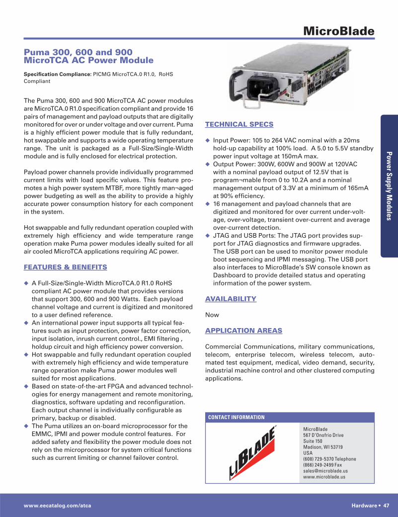
www.eecatalog.com/atca Hardware • 47
CONTACT INFORMATION
MicroBlade
MicroBlade567 D’Onofrio DriveSuite 150Madison, WI 53719USA(608) 729-5370 Telephone(866) 249-2499 [email protected]
TECHNICAL SPECS
Input Power: 105 to 264 VAC nominal with a 20ms hold-up capability at 100% load. A 5.0 to 5.5V standby power input voltage at 150mA max.Output Power: 300W, 600W and 900W at 120VAC with a nominal payload output of 12.5V that is program¬mable from 0 to 10.2A and a nominal management output of 3.3V at a minimum of 165mA at 90% efficiency.16 management and payload channels that are digitized and monitored for over current under-volt-age, over-voltage, transient over-current and average over-current detection.JTAG and USB Ports: The JTAG port provides sup-port for JTAG diagnostics and firmware upgrades. The USB port can be used to monitor power module boot sequencing and IPMI messaging. The USB port also interfaces to MicroBlade’s SW console known as Dashboard to provide detailed status and operating information of the power system.
AVAILABILITY
Now
APPLICATION AREAS
Commercial Communications, military communications, telecom, enterprise telecom, wireless telecom, auto-mated test equipment, medical, video demand, security, industrial machine control and other clustered computing applications.
Puma 300, 600 and 900 MicroTCA AC Power ModuleSpecification Compliance: PICMG MicroTCA.0 R1.0, RoHS Compliant
The Puma 300, 600 and 900 MicroTCA AC power modules are MicroTCA.0 R1.0 specification compliant and provide 16 pairs of management and payload outputs that are digitally monitored for over or under voltage and over current. Puma is a highly efficient power module that is fully redundant, hot swappable and supports a wide operating temperature range. The unit is packaged as a Full-Size/Single-Width module and is fully enclosed for electrical protection.
Payload power channels provide individually programmed current limits with load specific values. This feature pro-motes a high power system MTBF, more tightly man¬aged power budgeting as well as the ability to provide a highly accurate power consumption history for each component in the system.
Hot swappable and fully redundant operation coupled with extremely high efficiency and wide temperature range operation make Puma power modules ideally suited for all air cooled MicroTCA applications requiring AC power.
FEATURES & BENEFITS
A Full-Size/Single-Width MicroTCA.0 R1.0 RoHS compliant AC power module that provides versions that support 300, 600 and 900 Watts. Each payload channel voltage and current is digitized and monitored to a user defined reference.An international power input supports all typical fea-tures such as input protection, power factor correction, input isolation, inrush current control., EMI filtering , holdup circuit and high efficiency power conversion.Hot swappable and fully redundant operation coupled with extremely high efficiency and wide temperature range operation make Puma power modules well suited for most applications.Based on state-of-the-art FPGA and advanced technol-ogies for energy management and remote monitoring, diagnostics, software updating and reconfiguration. Each output channel is individually configurable as primary, backup or disabled.The Puma utilizes an on-board microprocessor for the EMMC, IPMI and power module control features. For added safety and flexibility the power module does not rely on the microprocessor for system critical functions such as current limiting or channel failover control.
Pow
er Supply M
odulesPow
er S
uppl
y M
odul
es

48 Engineers’ Guide to ATCA® & MicroTCA Technologies 2010
VIEWPOINT
For equipment manufacturers wanting to get LTE bases-
tations in the hands of customers for demos and trials
as quickly as possible, recent technology advances now
enable a better, faster way to a small footprint, cost-
effective eNodeB. New silicon developments can reduce
a wireless basestation to a single card with baseband
processors replacing DSPs, FPGAs, and NPUs. Such pro-
cessors can have an entire basestation application layer
on a single System on a Chip (SoC), thus greatly reducing
system latency. The single card modules can also include
the latest, industry-standard common public radio inter-
face (CPRI) functionality, plus high-speed serial RapidIO
(sRIO) and PCI Express I/O. On-chip hardware acceleration
for forward error correction (FEC) and encryption further
reduce overall system cost.
Such new modular basestation solutions address many
factors important to both equipment manufacturers and
their customers as well.
Advantages for the equipment manufacturer:• Simplified design, both electrically and mechanically, which
reduces basestation costs
• Use of bundled hardware/software/API enables focused
investment of resources in applications software and value-
add features vs. re-inventing the underlying wheel
• Accelerated development cycle for shorter time to market
and a competitive edge
• Extended market reach with technology for solutions that
were not previously feasible
Advantages for the LTE service provider:• Reduced plant space required due to smaller basestation
footprint
• Substantially reduced basestation power and cooling
requirements
• Ability to combine basestations with other functions rather
than requiring separate racks
• Increased price performance
• Enablement of new money-making services
Beyond the development and cost benefits, consider the
applications and services these new basestations can
enable across single and multiple sectors using Long Term
Evolution (LTE FDD and TDD), WiMAX air-interface stan-
dards, wideband code-division multiple access (W-CDMA),
and time-division synchronous code division multiple
access (TD-SCDMA, in China).
Private Applications• Rapidly deployable networks for public safety and the military
• Closed enterprise usage on cruise ships, oil platforms, and
aircraft, and in prisons
• Machine to machine usage beyond meter reading to asset
management and media downloads
Remote Radio Heads • Basestation/radio head integrated device
Public Carriers• Microcell
• Picocell
• Enterprise femtocell
In summary, the new highly-integrated basestation tech-
nology rolls formerly separate elements into a single
package, enabling a highly scalable, cost-effective, small
footprint basestation solution. Evolution is to the point
that initial models are available that reduce the size and
cost by at least half compared to currently deployed bases-
tation solutions. This game-changing technology will help
redefine wireless infrastructure economics during what is
expected to be a major basestation upgrade cycle.
Marc DeVinney, VP of Engineering at In-
terphase, [email protected].
by Marc DeVinney
Winning Technology for Small Footprint Wireless Basestation Designs