Embed Size (px)
Citation preview

7/27/2019 At Turbo Tech
http://slidepdf.com/reader/full/at-turbo-tech 1/20
Table of Contents
Background....................................2
Design Features.............................3
Construction Features................... .4
Custom Design & Manufacturing....5
Turbo Performance.........................6
Piping & Instrumentation.................9
Pump Selection w/ Turbo...............10
Installation......................................11
ComparisonImpulse Turbine vs. Turbo .......12
Comparison
PX vs. Turbo............................14
Interstage Boosting........................16
Dual Turbine System......................17
The AT Turbo like its generational predecessors recovers hydraulic
energy from the high pressure concentrate (brine) stream in the
reverse osmosis (RO) process and transfers that energy to a feed
stream. That feed stream may be seawater going into a single stage
RO membrane block, or it may be first stage brine stream being
boosted in pressure for a second stage membrane block for further
recovery of permeate.
This unique approach offers many advantages to the RO designer
and users. This manual will explain in detail these advantages and
innovations that make the AT Turbo the most efficient and cost ef-
fective energy recovery unit available today. The manual shows howto estimate Turbo performance as well as how to apply the Turbo to
a variety of RO systems.
About the AT Turbocharger
The AT Turbocharger represents a tech-
nological breakthrough in Reverse Os-
mosis energy recovery performance.
Advance turbo machine design soft-
ware, 3D CAD and CAM software plus5 axis machining now enables PEI to
custom design and manufacture com-
plex geometry impellers and casing flow
passages that have resulted in Turbo’s
efficiency increases of 40% or more.
World class efficiency plus all of the
other features and advantages of the
Turbo are explained in detail in this
manual.
harnessing the power of...
L I Q U I D E N E R G Y

7/27/2019 At Turbo Tech
http://slidepdf.com/reader/full/at-turbo-tech 2/20
2
AT Turbo Background
Like the previous generation PEI Turbos, the AT Turbo transfer pressure energy from one liquid stream to a second liquid
stream. However, with the use of new technology the AT Turbo does this energy transference much more efficiently.
The AT Turbo consists of a pump section and a turbine section. Both pump and turbine sections contain a single stage
impeller or rotor. The turbine rotor extracts hydraulic energy from the brine stream and converts it to mechanical energy. The
pump impeller converts the mechanical energy produced by the turbine rotor back to pressure energy in the feed stream.
Thus the AT Turbo is entirely energized by the brine stream. It has no electrical, external lubrication, or pneumatic require-ments.
Figure 1 illustrates the operation of the AT Turbo in a single stage SWRO system. The feed stream from the high pressure
pump provides a flow of 1000gpm (227m3/hr) at a pressure of 588psi (40.5bar) to the pump section of the Turbo. The impelle
in the pump section increases the total feed stream pressure to 1000psi (68.9bar). The membrane block produces 400gpm
(90.9m3/hr) of permeate and rejects 600gpm (136m3/hr) of brine. The brine, which is now at a pressure of 980psi (67.5bar)
enters the turbine section of the AT Turbo. The turbine rotor depressurizes the brine while extracting the energy in the form of
high speed rotational torque. The brine, now depressurized to 5psi (brine exhaust can be any value, even hundreds of psi) is
exhausted to the discharge piping.
It is readily apparent that the reduced discharge pressure of the high pressure pump will have a large effect not only on
reducing operating cost, but also on reducing both initial capital and maintenance cost. More details on this important aspec
of the AT Turbo Total Life Cycle Cost will be explained later.
Also note, the Turbo eliminates the brine control valve, which is another major expense and maintenance item in SWRO
plants. Further note, that the Turbo is mechanically independent of the high pressure pump. Thus the Turbo can be used with
any type of feed pump and without any modifications to the pump, motor, or base.
In a later section of the manual the use of the Turbo in multi stage SWRO systems will be explained and again it will clear tha
the Turbo is more than just energy recovery. The Turbo, which incorporates a pump with a turbine into a single unit, opens
many new possibilities for the RO designer.
Figure 1
7/27/2019 At Turbo Tech
http://slidepdf.com/reader/full/at-turbo-tech 3/20
Design Features:The Turbo addresses the major issues facing the RO system
designer and user, including simplicity of design and opera-
tion, efficiency, reliability, ease of field servicing and versatil-
ity of use through the following design features.
• Type: The Turbo is an integral turbine driven cen-trifugal pump. The turbine is a single stage radial in-
flow type. The pump is a single stage centrifugal type
with its impeller mounted on the turbine shaft. The
unit is entirely energized by the high pressure brine
stream.
• Casing: The US Patent Pending AT Turbo casing
consists of an outer pressure casing designed for
1500 psi maximum pressure and inner radially split
volute insert casing. The volute insert is designed
by CFD software and completely machined on CNC
milling machines, thereby achieving the ultimate in
dimensional control, surface finish, and hydrualic ef-
ficiency.
• Impellers: The AT Turbo’s feature custom engineered
AND manufactured impellers. Using the most ad-
vance computational fluid dynamics pump and tur-
bine design software, 3D CAD and CAM systems
and 5 axis milling machines, each impeller design is
optimized and manufactured for maximum efficiency.
• Balancing: The entire rotating assembly is balanced
to ISO G3 standards (gyroscope tolerance) on PEI’s
computer controlled high speed balancer.
• Bearing: The Turbo uses three bearings all of which
is lubricated by the feed or brine flow. The pump and
turbine center bearing are the hydrodynamic journal
type. The thrust bearing is of the hydrostatic type which
utilizes high pressure water in an annular groove to
balance net rotor axial thrust. Standard material for
all bearings is resin impregnated carbon graphite.
Optional material is solid ceramic aluminum oxideUnits equipped with ceramic bearings also use a
plasma sprayed ceramic coating on the shaft bearing
surfaces.
• Shaft Seals: Shaft seals or more precisely the lack
of shaft seals is one of the outstanding design fea-
tures that contribute to the Turbo’s high reliability. Me-
chanical seals or shaft packings are the most main-
tenance intensive parts on nearly all pumps and are
responsible for the most downtime. And because the
Turbo’s rotor is fully enclosed by the casing, there
are no shaft penetrations to the atmosphere, hence
no seals.
• Multiple Turbine Nozzles: The Turbo is equipped
with two nozzles and a control valve that allows brine
flow and pressure to be regulated without energy
wasting throttling or bypassing. See page 8 for addi-
tional information on this important feature.
• Pipe Connections: All feed (pump) and brine (tur-
bine) pipe connections are Victaulic type. For larger
units or very high pressure applications ANSI 600#
class flanges are available.
• Unit Base: Turbo bases are available in Delrin plas-
tic, stainless steel, or painted carbon steel. All bases
are bolted with SS bolting and are drilled for sole plate
bolting.
Figure 2

7/27/2019 At Turbo Tech
http://slidepdf.com/reader/full/at-turbo-tech 4/20
4
Operation and
Construction FeaturesBesides its outstanding efficiency, the AT Turbocharger
brings many benefits, some obvious, and others not
so obvious, however, they all add up to increase total
value to the RO designer and user. Consider the fol-
lowing Turbo characteristics:
1. Fexibility of installation, can be placed next toRO block, greatly reduces brine piping cost
– no double shaft motors, brine sumps, ex-
tended bases and foundations.
2. Significantly reduces high pressure pump size
(number of stages), motor size, motor starter,
switch gear and transformers
3. Able to discharge brine against backpressure
– no brine sump or pump
4. Brine is not exposed to atmosphere, thereby
minimizing odor and corrosion
5. Reduces load on high pressure pump –
resulting in greater pump reliability – shorter
and stiffer shafts for centrifugal pumps,
reduced frame and crankshaft loading and
cooler oil temperatures for positive
displacement plunger pumps.
6. Can be used with any type of high pressure
feed pump.
7. Turbos are very compact, small space and
foundation requirements
8. Turbo do not generate flow or pressure
pulsation
9. Low noise and vibration operation – Turbo also
reduces high pressure pump noise
10. No shaft seals – very high reliability11. No oil or grease lubrication – bearings are
water lubricated
12. Brine pressure and flow regulated with Turbo
auxiliary nozzle and valve, no energy wasting
throttling or bypassing
Materials of Construction
The standard and optional material of construction for AT Tur-
bocharger are:
Part Standard Optional
Casing Duplex Stainless Super Austenitic
Steel Stainless Steel
Alloy 2205 AL6XN
Impellers AL6XN
Bearings Resin/ Ceramic:
Carbon Graphite Aluminum Oxide
Retaining Rings SS316 Passivated
External Bolting SS304
Duplex alloy 2205 is a superior material for crevice and pitting
corrosion resistance in high chloride environments. Alloy 2205
has twice the tensile strength of SS316L . The welding char
acteristics of 2205 are very good and post weld heat treat-
ment to maintain corrosion resistance is not required. The
nominal composition of Alloy 2205 is:
Cr 22%
Ni 5%
Mo 3%
N 0.15%
Fe balance
Custom engineering impellers utilizing turbomachine design
software.
TESTING All Turbochargers are individually tested for performance
mechanical integrity, and hydrostatic pressure. All data acqui
sition is by electronic instrumentation and computer interface
Test data is documented to identify the unit test and test con
ditions. The complete test report becomes a part of the unit’s
job history file.

7/27/2019 At Turbo Tech
http://slidepdf.com/reader/full/at-turbo-tech 5/20
Customer Specific Hydraulic Design
And ManufacturingIn the past, every Turbo was designed and manufactured to
achieve its best efficiency point (BEP) at the customer’s spe-
cific duty point. Casing hydraulic passages (volute, diffuser,
and nozzles) were machined to the correct dimensions for
duty point operation. The cast impellers were trimmed for
maximum efficiency at the design reject ratio. The AT Turbo,however, goes much beyond that already high level of cus-
tom engineered equipment produced by PEI.
Now, thanks to a highly disciplined design process which in-
cludes computational turbo machine software, 3D CAD and
CAM software and 5 axis CNC milling machines, PEI can cre-
ate a completely unique turbochargers with turbine rotor and
pump impellers designed with complex 3D blade geometry.
The results of this process, plus the inherent efficiency ad-
vantage of high speed operations, are simply the most effi-
cient pumps and turbines available today.
Machined wax turbine impeller for
investment casting.
3D machining accomplished through use of Master Cam
software and 5 axis machining center.
HAAS 5 axis machining center.
*Custom Machined Volute Insert technology
patented by Pump Engineering, Inc.
DATA: Customer
Requirements
Generate hydraulic design
Generate CNC program
Machine volute inserts*
Hydro & Performance Test
Unit ready for shipping
OK
TEST
YES
NO
Machine AT 3D impellers

7/27/2019 At Turbo Tech
http://slidepdf.com/reader/full/at-turbo-tech 6/20
6
AT TURBO PERFORMANCEGenerally, an energy recovery turbine (ERT) is rated as hav-
ing a certain efficiency based on the conversion of hydraulic
energy into mechanical shaft energy. However, in reverse os-
mosis where the process is driven by pressure energy, the
shaft energy generated by the ERT is normally transferred to
the feed pump which then converts that energy back into pres-
sure energy in the feed stream.
The most accurate measure of ERT efficiency for an RO sys-
tem is the ratio of hydraulic energy returned to the feed stream
to the amount available in the brine stream. This ratio is called
the Hydraulic Energy Transfer Efficiency (HETE), or nte
and is defined as:
Nte = Hout
/ Hin
[1]
Where Hout
= Hydraulic energy transferred to the feed stream
Hin
= Hydraulic energy available in the brine stream
The Hydraulic Energy Transfer Efficiency provides the tru-
est method to evaluate and compare the energy recovery ef-
fectiveness of all energy recovery devices, including impulseturbines, flow work exchangers, as well as the Turbo.
Unlike conventional ERTs, the energy transfer efficiency of
the Turbo is independent of pump efficiency. The reason for
this is that the Turbo contains its own pump, so the complete
energy transference occurs within the Turbo. So unlike an
impulse turbine or reverse running multistage pump, the
Turbo’s rotor speed is completely independent of the motor/
high pressure pump. This means the Turbo can be designed
for high speed operation which is the most efficient and cost
effective design. Pump efficiencies of 90%+ are possible for
larger AT Turbos.
The useful work of the AT Turbo is expressed as the “Boost
Pressure”. This is the pressure rise that occurs between the
Turbo’s pump inlet and pump discharge. To apply the Turbo
to an RO system, the boost pressure needs to be calculated.
Use Figure 3 to find the approximate Hydraulic Energy Trans-
ference Efficiency for the Turbo. For example, at a feed flow
rate of 1000gpm the AT Turbo displays an nte of about 73%.
FIG 3 AT Turbo Hydraulic Energy Transfer Efficiency (nte)
Knowing nte makes calculation of the Turbo pressure boost,
∆∆∆∆∆P, very simple:
∆∆∆∆∆P = (Nte) (Rr) (Pbr – Pe) [ 2 ]
Where Rr = ratio of brine flow to feed flow
Pbr = brine pressure at turbine inlet
Pe = exhaust pressure of Turbo
(brine pressure leaving Turbo)
The brine pressure drop, ∆∆∆∆∆Pbr is defined as:
∆∆∆∆∆Pbr = Pbr – Pe [ 3 ]
Now substituting numerical data into our formula for the
1,000gpm (227m3/hr) example as follows:
Qf = 1,000gpm (feed flow)
Qb = 600gpm ( brine flow)
Qp = 225gpm(product flow)
y = 40% (recovery ratio)
Rr = 60% (reject ratio)
Pm = 1,000psi (membrane pressure)
Pbr = 980psi (brine pressure)
Pe = 5psi (brine exhaust pressure)
A design objective is to make ∆P as large as possible to ob-
tain maximum energy recovery. Equations [ 2 ] and [ 3 ] indi-
cate that increasing ∆∆∆∆∆Pbr will accomplish that. Since Pbr is
usually a given value based on membrane design, try to keep
turbine exhaust pressure to a minimum safe level. Although
the AT Turbo can discharge brine at a high pressure, this ex-haust pressure does reduce the available recoverable energy
In this example the use of the AT Turbo reduced the high
pressure feed pump discharge pressure from 1000psi to 588
psi. Thus not only will the AT Turbo system be the most en-
ergy efficient, but it will contribute considerable capital cost
savings as well.
A Note on Energy Efficiency Comparisons
When comparing the stated efficiency of the Impulse Turbine
and Reverse Running Pump Turbines with the Turbo’s Hy
draulic Energy Transfer Efficiency, be aware that their effi
ciencies are given as the ratio of mechanical shaft output tobrine energy input. To get a true comparison of Hydraulic
Energy Transfer Efficiency to mechanical efficiency, multi-
ply the Impulse Turbine efficiency by the feed pump efficiency
and any other component such as a V belt speed reducer
Variable Frequency Drive or part load reduction of motor effi
ciency. As an example, a 86% efficient Impulse Turbine
coupled to a 77% efficient centrifugal pump would have com
bined efficiency Hydraulic Energy Transfer Efficiency o
66.2%. Further if a full sized motor were used, there would be
a reduction in motor efficiency due to part load operation tha
would now bring nte to 64.8%.
Thus the 64.8% nte of the Impulse Turbine/Pump and not the86% mechanical efficiency, is the true measure of Energy
Recovery Turbine efficiency.
∆∆∆∆∆P = ( .73 ) ( 600gpm/1000gpm ) * ( 980psi – 5psi ) = 427

7/27/2019 At Turbo Tech
http://slidepdf.com/reader/full/at-turbo-tech 7/20
E f f i c i e
n c y ( % )
Feed Flow (gpm)
HTC-AT Efficiency Curve
HTC-AT Efficiency Chart
600 gpm
980 psi
Extra high pressure brine piping
Pelton Impulse
Turbine
86% efficiency
294 hp Output
1000 hp Motor
motor net power
467 hp
High Pressure
7 stage pump
77 % efficiency
1000 gpm
1000 psi
Pump Power =
761 hp
1000 gpm
30 psi
PIT Transfer efficiency = .86 (PIT n) x .98 (*) x .77 (pump n) = 64.8% nte
1000 gpm
585 psi00 hp motor
AT 900 Turbo
(placed next to membrane
rack for reduced piping)
Pump Power = 420 hp
1000 gpm
1000 psi
71% nte
1000 gpm
30 psi
High Pressure
4 stage pump
77% efficiencyTurbo Transfer efficiency = 71% nte
* percentage reduction of motor efficiency due to part load operation
600 gpm
980 psi
600 gpm
5 psi
Figure 3
Figure 4
Figure 5

7/27/2019 At Turbo Tech
http://slidepdf.com/reader/full/at-turbo-tech 8/20
8
Volute
Auxiliary No
TurbImp
Valve
Auxiliary Nozzle
Primary Nozzle
Brine
AT Turbocharger Auxiliary Nozzle and Valve
All AT Turbocharers (see Fig 6) are equipped with a Main Nozzle and a secondary Auxiliary Nozzle (AN) and Auxiliary Nozzle
Control Valve (ANCV). The Main Nozzle is sized to provide a concentrate system resistance (concentrate pressure) equal to
the maximum design pressure at the design concentrate brine flow rate.
The auxiliary nozzle is sized to about 20-25% of the area of the Main Nozzle.
The ANCV controls flow to AN in the turbine casing. The ANCV will provide
a 20-30% pressure range at a constant brine flow.
Note that the ANV does not bypass flow around the
Turbo. It is a unique way to achieve variable area
nozzle flow without the energy wasting throttling and
bypassing valve arrangements needed by constant
speed reverse running pump turbines.
The ANCV can be supplied either as a manual or
as a power actuated unit.
AT Turbocharger Installation and PID
For single stage seawater RO systems, the Turbo is locatedhydraulically between the discharge of the high pressure feed
pump and the membrane block. Its actual physical location can be optimized to reduce the length of both brine and feed
piping. A brine control valve is not needed when using the Turbo. Brine pressure and flow can be trimmed through use of the
Auxiliary Nozzle Control Valve (ANCV).
Fig. 7 is a preferred PI&D arrangement of a turbo installation for non VFD driven centrifugal feed pump motors. Note that a
flow control valve (FCV) is used to throttle pressure for membrane recovery control. The FCV is used in conjunction with the
ANCV to achieve the proper flow capacity and pressure. The FCV is opened or closed to maintain the required flow rate, while
the ANCV is open to operate the membrane at a lower pressure and closed to operate the membrane at a higher pressure.
Figure 6
Figure 7

7/27/2019 At Turbo Tech
http://slidepdf.com/reader/full/at-turbo-tech 9/20
Piping and Instrumentation Diagrams
Figure 8 Two Stage - Brine staged utilizing AT
Turbo as interstage booster pump.
Figure 9Second Pass - utilizing AT Turbo as
interstage booster pump.
Figure 10 Single stage SWRO with PD pump.
7/27/2019 At Turbo Tech
http://slidepdf.com/reader/full/at-turbo-tech 10/20
10
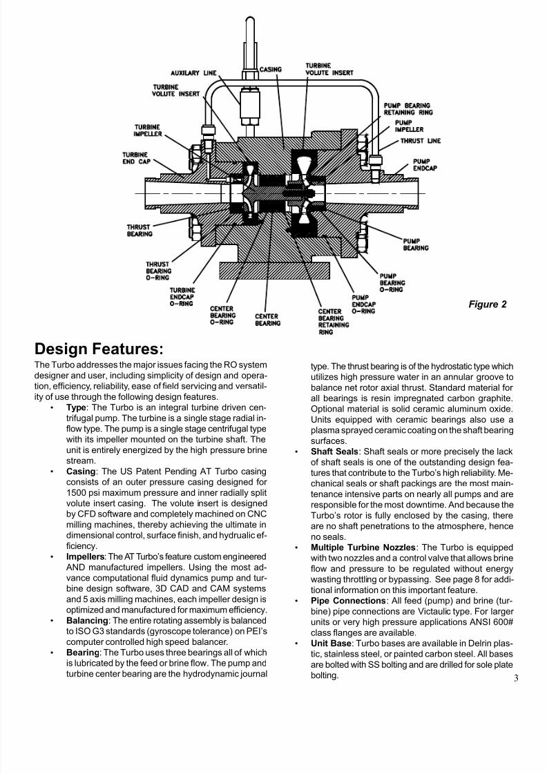
Pump selection with the TurboTM is easy, although a few guide-
lines should be followed. Always use the highest expected
pressure conditions in calculating TurboTM pressure boost. This
would typically be the pressure at the end of the membrane
life with the highest expected TDS feed at the lowest expected
temperature.
If the recovery or feed flow may vary significantly, it is a good
idea to check with PEI to ensure the TurboTM can efficiently
accommodate the conditions.
Positive Displacement Pumps
With positive displacement (PD) pumps such as reciprocat-
ing plunger types, flow rate is established by pump displace-
ment and RPM. Membrane pressure is controlled by adjust-
ment of the ANCV on the TurboTM. PD pumps do not need
any type of feed pressure control device such as a feed throttle
valve.
Due to the very high reliability of the TurboTM, the PD pump
and motor can be rated to deliver the required pump discharge
pressure allowing for the Turbo
TM
boost. Such downsizing of the pump and motor will save considerable capital and main-
tenance costs and energy use.
CAUTION! Always use good pulsation dampening on the
feed pump discharge. Severe flow and pressure pulsations
can be damaging to pressure gauges, flow meters, piping and
possibly the TurboTM . See PEI’s installation manuals for addi-
tional information
Centrifugal Pumps
These pumps must be sized for maximum pressure condi-
tions. When the required membrane pressure is lower than
the rated pump discharge pressure excess pump deliverypressure must be eliminated.
A feed throttle valve is the most common way to regulate this
pump pressure. This valve is partially closed during initial
Feed Pump Selection with the AT Turbooperation of the plant. As the membrane pressure require
ment increases with plant age, the valve is opened to obtain
increased pressure to the RO train.
Another way is to use a variable speed pump drive such as a
variable frequency drive (VFD). The pump speed is adjusted
as required to obtain the desired pump pressure. The advan
tage of this technique is that the pump power consumption is
minimized and the expensive control valve can be eliminated
Centrifugal Pump Example
The goal of this analysis is to find the performance require
ments of the feed pump. Operating conditions are indicated
in Figure 11 including the projected lowest and highest mem
brane pressure.
Figure 11 indicates a TurboTM transfer efficiency of 64%. Us
ing “end of life” conditions, equation [3] calculates the TurboTM
boost (i.e. the pressure rise between points 2 and 3) as 352
psi. The required feed pump discharge pressure, Pp, is:
Pp
= Pm
– Ptc= 950 – 386 = 564 psi
Thus, the feed pump must be sized to deliver 550 psi outle
pressure.
For start-up conditions, the TurboTM boost is 348 psi which
yields a TurboTM feed inlet pressure of 536 psi. Note that the
feed throttle valve must be adjusted to “destroy” about 61 ps
of feed pressure.
If a VFD were used, the control valve would be eliminated
and the feed pump power consumption would be reduced
For this example, the pump for start-up condition without theVFD would require 184 hp. With a VFD, the input power drops
to 176 hp.
Please contact PEI with questions about feed pump selec
tion.
Feed Throttle
Valve
ηηηηηp
= 72%
ηηηηηm
= 93%
Feed
Pump
AT TurboTMηηηηηte = 64%
Start-up End of LifeFlow Pressure Flow Pressure
(gpm) (psi) (gpm) (psi)
1 420 30 420 30
2 420 564 420 564
2’ 420 502 420 564
3 420 850 420 950
4 280 830 280 920
5 280 5 280 5
’
Figure 11

7/27/2019 At Turbo Tech
http://slidepdf.com/reader/full/at-turbo-tech 11/20
InstallationCharacteristics of the AT Turbo that effect its installation in typical SWRO plant are as follows:
Compact Size and Weight
Because of its high speed operation, an AT Turbo is much smaller than an equivalent capacity motor driven pump, as
much as five to tens times smaller. For instance a 100gpm Turbo ways 40lbs vs 400lbs or more for a high pressure pump.
This factor makes it ideal for skid mounted or containerized system, where space restrictions are always an important
consideration.
Flexible Installation Location
The Turbo is mountable in any orientation. Units up to the AT 100 can be supported by its piping. For larger system thathave separate pump rooms, the Turbo ability to downsize the pump, motor, and associated electrical equipment will result
in a smaller building. Additionally, the Turbo can be located anywhere between the high pressure pump discharge and the
feed header to the membrane block. By placing the Turbo next to the membranes, considerable savings of high pressure
super alloy piping can be made.
Piping and Foundations
Victaulic pipe connections are standard on the AT Turbo from model AT 25 through model AT 2400. ANSI 600lb class
flanges however are available on all AT Turbo models and are standard equipment on models AT3600 and larger. Because
of their relatively small size and vibration free operation foundation requirements are very modest and are primarily de-
signed to support piping loads that the Turbo may be carrying.
Low Noise and Pulsation Free Flow
Highly efficient hydraulic design of the AT Turbo significantly minimizes noise generation to such an extant that it is not
audible over the background noise of a typical SWRO plant. In addition, because the Turbo downsizes the high pressure
pump and motor size and pressure requirements, there is a noise reduction associated with this equipment. The high
speed centrifugal principle of Turbo operation assures pulsation free smooth flow to the membranes.
Pressurized Brine Discharge
The AT Turbo can discharge brine (concentrate) against practically any level of backpressure. So there is never any need
for brine disposal pumps or gravity flow piping or trenches.
AT Turbo Recommended Requirements
· Pressure gauges or transducers should be installed near each Turbo pipe connection to permit monitoring of
Turbo performance.
· Suction Stabilizers and Discharge Pulsation Dampeners should always be used with reciprocating positive dis-placement pumps
· Perform all pipe cleaning and flushing before final installation and start up of the Turbo
Maintenance and OverhaulThe AT Turbo has no scheduled maintenance requirements. There are no shaft couplings to align, no shaft seals (lead-
ing cause of pump failure), no lubrication system or lubricants (second leading cause of pump failure), and no external
auxiliary services such as cooling water or pneumatic requirements.
See the Installation and Operation Manual for complete information.
Overhaul and Repair Thanks to its relative small size and single stage design, even the largest Turbo can be completely inspected and/or
overhauled in a few hours. All bearings are slip fit and O ring mounted, making their removal and installation a quick,
simple, and straightforward job. PEI stocks all parts necessary for any repairs that may occur.

7/27/2019 At Turbo Tech
http://slidepdf.com/reader/full/at-turbo-tech 12/20
12
Comparison of the AT Turbo and Pelton Impulse Turbine
As explained in the AT Turbo Performance section of this manual, Hydraulic Energy Transfer Efficiency is the only accurate
method of comparing Energy Recovery Devices. In this section,AT Turbo performance will be compared to a Pelton Impulse
Turbine performance for a relatively large SWRO train size of 2,641,000gpd (10,000m3/d). The comparison will cover the
entire hydraulic operating envelope from minimum to maximum membrane pressure requirements.
Example RO System Conditions:
Fluid: Seawater TDS 38,000 Temperature: 14 – 290 C Capacity: 2,641,000 gpd (10,000m3/d)
290C Summer Conditions - 0 years 140C Winter Conditions - 3 years
Feed 3986 gpm (906 m3/hr) 3986 gpm (906 m3/hr)
Flow
Pump 920 psi (63.4 bar) 1085 psi (74.8 bar)
Pressure
Membrane 885 psi (61 bar) 1050 psi (72.4 bar)
Pressure
Concentrate 2232 gpm (507 m3/hr) 2232 gpm(507 m3/hr)
Flow
Concentrate 865 psi (59.7 bar) 1030 psi (71bar)
Pressure
From the above membrane manufacture recommended design data, the extremes of throttle pressure is 200psi (maximum
pump discharge pressure 1085psi – minimum membrane pressure 885psi). This total pressure range defines the basic
Hydraulic Operating Envelope. At those times of reduced pressure operation, the excess pressure will be throttled by flow
control valve.
Presented below are the performance factors for an AT 3600 Turbocharger and a Pelton Impulse Turbine and centrifugal
high pressure pumps
AT 3600 + pump Pelton Impulse Turbine+ pump
Feed Pump Flow 3986 gpm (906 m3/hr) 3986gpm (906 m3/hr)
Turbo Boost Pressure (max) 433psi (29.9 bar)
Feed Pump Discharge Pressure 652psi (45 bar) 1085 psi (bar)
Feed Pump Efficiency .85 .85
Motor Efficiency .95 .95
Pelton Impulse Turbine Efficiency n/a .89
Hydraulic Transfer Efficiency .78 .748
The graph below depicts the performance of the AT 3600
and the Pelton Impulse Turbine over the Hydraulic Operating
Envelope defined above. Note that the pressure throttling
significantly diminishes the amount of recoverable concen-
trate energy available to the Impulse Turbine. In fact, the
pump discharge pressure throttling energy loss can be 20%
or more of total pumping energy and represents the greatestsource of loss and inefficiency in most SWRO high pressure
circuits equipped with Impulse Turbines.

7/27/2019 At Turbo Tech
http://slidepdf.com/reader/full/at-turbo-tech 13/20
750 800 850 900 950 1000 1050
2936
2176
2109
2039
1969
1899
18301763
1650
1500
1750
2000
2250
2500
2750
3000
3250
Membrane Pressure (psi)
Pressure Throttling with a Turbocharger Another advantage of feed stream pressure boosting with the Turbo is a reduction in throttling pressure differential. Taking the
above example, where there is 200psi difference between minimum and maximum membrane operating pressure, the AT
Turbo reduces the amount of throttling from 200psi to 130psi. Because Turbo Boost Pressure (TBP) is a function of Brine
Differential Pressure (BDP), the TBP in the example decreases from 433psi at a BDP of 1030psi to 364psi at a BDP at 865psi
The reduction in throttling pressure differential results in lower noise, less wear, and cavitation in the flow control valve.
HTC AT Benefits
• Feed pump and motor layout not affected.
• HTC AT can be located anywhere, including next to
the RO trains, reducing the amount of high pressure
piping.
• The HTC AT is able to discharge brine against any
backpressure and a brine disposal pump or sump is
not needed.
• The turbo boost pressure provided by the HTC AT
reduces the discharge pressure the main feed pumpmust produce thereby allowing for a pump with fewer
stages.
• Motor size reduced by 30% - 50%.
• Smaller transformer and motor starter or VFD
• The HTC AT is maintenance free! All three bearings
are process lubricated.
• No increase in power over complete membrane
pressure envelope.
• Brine flow and pressure can be regulated with reduced
energy-wasting throttling or bypassing.
• Small footprint and Victaulic pipe connections ensure
easy installation.
Pelton Impulse Turbine (PIT)
• PIT is connected to pump – a modified base plate, second
shaft and coupling are required.
• PIT must be located next to the pump. Pump room mus
accommodate longer base plate and heavier pumping
equipment.
• Brine sump with pump or gravity flow piping required
Level switches, alarms and valves may be needed too.
• Must develop full membrane pressure with main feed
pump requiring maximum number of pump stages.
• Full size motor with a double extended shaft may be
required. No size reduction in transformer or starter.
• Oil/grease lubricated bearings need periodic inspection
and maintenance. Brine disposal pump requires
additional maintenance. Large number of pump stages
increases the cost of spare parts. Double extended shaf
motor may be difficult to replace on an emergency basis
HTC AT vs. Pelton Impulse Turbine – a side by side comparison
Pump hp
with PIT
Net Motor
with PIT
Pump hp
with HTC
Figure 12
F l o w

7/27/2019 At Turbo Tech
http://slidepdf.com/reader/full/at-turbo-tech 14/20
14
Comparisons of the AT Turbo and the Pressure Exchanger
The Hydraulic Energy Transfer Efficiency of the Pressure Exchanger in RO service can be determined by analysis of the
efficiencies of all the components that are part of the high pressure circuit.
Fig 14 shows the PX system. Note that its basic design is comprised of the PX device, a high pressure pump, a booster pump
Additional and necessary components such as high pressure flow meters and valves have a minor effect on overall HETE, s
for sake of simplicity will not be considered in the energy analysis.
The PX Exchanger system uses two pumps. One pump’s capacity equals the permeate flow plus an additional flow equal to
the internal leakage losses of the PX, typically 3 – 4% of brine flow. This pump has to achieve the full membrane pressure
required by the feed water salinity plus an additional pressure head required by the increase in feed salinity due to brine mixin
in the PX device. The second pump is a booster pump whose capacity equals the brine flow and whose head rise equals th
membrane pressure loss (20 – 50psi) plus the inlet and outlet pressure losses of 20 – 25psi per each end of the PX device
giving a total differential pressure of 60 – 100psi.
Example 150,000gpd SWRO plant (49.5gpm permeate, 111gpm feed)
operating at 45% recovery at a membrane pressure of 1,000psi
Thus the HETE of the PX Exchanger device is .658. Compare this number to the advertisedclaims of 94% efficiency for the PX. The difference between the claimed efficiency and true
HETE is in the losses due to internal leakage and inefficiencies of the booster pump. Addi-
tional losses will be produced by valve(s) necessary to control the PX.
AT Turbocharger System
For the Turbo example, first calculate AT Turbo boost
pressure utilizing the following forumula:
Reject Ratio x AT Turbo HTE x Brine Diff. Pres. = Turbo Boost
.55 x .60 x 995 psi = 322 psi Boost
The high pressure pump differential pressure then is:
1000psi (membrane pressure) – 20psi(suction pressure) –
322psi (turbo boost pressure) = 658psi
Reciprocating Plunger Pump Efficiency =. 85 (including V
belt losses).
60hp electric motor efficiency = .92
Total Pump Motor Power = 111 x 658 x .0005831/.85/.92 x
.746 = 40.62kW
Permeate Energy Rate is 13.67kW/1,000gal or 3.64kW/m3
PX Pressure Exchanger System
PX High Pressure Pump:
Q = 49.5 x 1.04 (internal leakage factor) = 51.5gpm
P = 995psi (1,000psi – 20psi suction pressure +
15psi Salinity Mixing Factor)
Reciprocating Plunger
Pump Efficiency = .84 (including V belt drive losses)
40hp motor efficiency = .90
Total Pump Motor Power *= 51.5 x 995 x .0005831/.84/.90 x .746 = 29.48 kW
Booster Pump: Q = 61.5gpm
P = 75psi
Pump used for this application will be a multistage centrifu-
gal with BEP efficiency of .52. 7.5 hp motor efficiency = .88
Total Pump Motor Power = 61.5 x 75 x .0005831/.52/.88 x
.746 = 4.38kW
Total energy usag: 33.86kW
Permeate Energy Rate: 3.04kW/m3 or 11.40kW/1,000gals
* Total Pump Motor Power hp = Q x P x .0005831/ pump efficiency/ motor efficiency/
vfd efficiency (if used)
Where Q = Pump Capacity in gpm
P = Differential Pressure Rise in psi
.0005831 = Water Horsepower Constant

7/27/2019 At Turbo Tech
http://slidepdf.com/reader/full/at-turbo-tech 15/20
PX High Pressure Pump:Q = 347gpm x (430 x .04) (internal leak factor) = 364gpm
P = 1045psi (1050psi – 20psi (suction pressure + 15psi
Salinity Mixing Factor)
The most reasonable choice for a high pressure feed pump
is a multistage centrifugal. A well designed segmental ring
type such as, Flowserve 4x11 A, will display an efficiency of
64.2%.
Total Pump Motor Power =
364 x 1045 x .0005831/.70 /.93 x .746 = 277 kW
Booster Pump selection would be an API 610 class single
stage centrifugal rated for 1,000psi suction pressure and
with an efficiency of .72Booster Pump: Q = 771gpm
P = 75psi
Booster Pump Motor Power =
424 x 75 x .0005831/.72 / .92 x .7457 = 20.87kW
Total energy usage: 298 kW
Permeate Energy Rate: 14.3 kW/1,000gals or 3.85kW/m3
For the AT Turbo example, first calculate the Turbo Boost
Pressure by:
Reject Ratio x AT Turbo HTE x Brine Differential Pressure
.55 x .721 x 1025psi = 406.5 psi
The high pressure pump differential pressure then is:
1050psi (membrane pressure) – 20psi (suction pres-
sure) – 406.5 psi (turbo boost pressure) = 623.5 psi
High Pressure Pump: Because the feed flow is higher (771gp
vs 347gpm) with the AT Turbo system a more efficient fee
pump is available. A typical axial split case multistage volu
pump displays an efficiency of .79 at this flow rate. 400hp Eletric Motor efficiency = .94
Total Pump Motor Power:
771 x 623.5 x .0005831/.79 /.94 x .7457 = 281.48kW
Permeate Energy Rate:13.52kW/1,000gals or 3.57kW/m3
Example 2500,000gpd SWRO plant (347gpm permeate, 771gpm feed) operating at 45% recovery with a membrane pressure of 1,050p
PX Pressure Exchanger System AT Turbocharger System
In the above example the HTE of the PX Pressure Exchanger is .647. It is clear in the second
example the AT Turbo is more efficient. However, efficiency is just one of many factors to
consider in energy recovery equipment selection. Capital cost, reliability, maintainability, ease
and simplicity of operation and control are other important factors, and in some cases more
important than efficiency alone. In all these areas, the AT Turbo is superior to the PX device.
Figure 13
Figure 14

7/27/2019 At Turbo Tech
http://slidepdf.com/reader/full/at-turbo-tech 16/20
16
The Dual Turbine System:
A Cost Effective and Reliable Method of Eliminating Pressure Throttling in RO Systems
In the comparison of AT Turbo and Pelton Impulse Turbine performance (page 12-13), the effects of feed stream throttling were clearly
noted. This type of energy loss is especially prominent with SWRO plants that see wide annual salinity and/or temperature changes.
There are a number of ways to minimize these losses. Permeate throttling can reduces these losses somewhat. Using variable
frequency drives (VFD) with centrifugal pumps to change motor driver speed, hence pump discharge pressure is a more effective
method to minimize pressure throttling. However VFD equipment for large plants is very expensive and VFD generate their own losses
of 2-3%. Additionally, as speed is changed to accommodate pressure changes, pump capacity also changes, which may result in
unacceptable capacity to the membrane
To address the problem of pressure throttling in SWRO plants, PEI has developed the Dual Turbine System (DTS) for both single stage
and two stage plants.
Figure 15 (left) and illustrates the DTS for
maximum energy recovery in SWRO
plants.
M
P T
3986
885
39866673986 gpm
30 psi
653 gpm
865 psi
1499 gpm
865 psi
PIT
Net Motor hp 1442
High Pressure
Pump 84% eff.
84% eff.
1834 gpm
0 psi
M
P TInterstage HTC
Control Valve
Reverse
Running
Pump
Turbine
Per
Figure 16 (right) and illustrates another DTS de-
sign utilizing the BCS two stage design with a
reverse running pump as the secondary turbine.Other design options include using an additional
TurboCharger to lower first stage pressure re-
quirements.

7/27/2019 At Turbo Tech
http://slidepdf.com/reader/full/at-turbo-tech 17/20
All pressure throttling is eliminated without resort to expensive VFD. The Impulse Turbine is of modest size (specific size depends on
flow conditions) and inexpensive compared to pressure throttling losses or a VFD. There are many variations to the basic DTS design.For instance reverse running pumps or additional Turbos can be in the place of the Impulse Turbine. However in most cases the
Impulse Turbine is a good choice because of its excellent part load efficiency.
For a complete Dual Turbine energy analysis, please contact Pump Engineering.
The Dual Turbine System (continued)
Energy Rate
750 psi - 1050 psi
DTS PIT
2.26 - 2.95 kW/M3 3.90 - 3.16 kW/M3
750 800 850 900 950 1000 1050
2936
21762109
2039
19691899
1830
1763
1650
1261 1317 1377 1440 1507 1577 1650
1200
1450
1700
1950
2200
2450
2700
2950
3200
Membrane Pressure (psi)
Pump hp
with PIT
Net Motor hp
with PIT
Pump hp
with HTC
Net Motor hp
with DTS
Fig. 15 shows a parallel flow arrangement of a AT Turbo as a feed pressure booster and a smaller Pelton Impulse Turbine as a
secondary ERT. Fig 16 is a similar arrangement, but with the AT Turbo being used as a interstage booster pump. In both cases the
method of operation is the same. At those times when Turbo boost pressure plus high pressure pump discharge pressure is in excess
of membrane requirements, a valve will open to divert flow from the turbine of the AT Turbo to the Impulse Turbine. Thus the AT Turbo
becomes a controllable variable speed pump, providing only sufficient pressure for the membrane process. The high pressure pump
runs at constant speed and output at its Best Efficiency Point. The Impulse Turbine recovers the concentrate energy not required by
the Turbo.
Figure 17
F l o w

7/27/2019 At Turbo Tech
http://slidepdf.com/reader/full/at-turbo-tech 18/20
18
Today, with the use of high pressure membranes (100bar), it is now possible to design two stage seawater reverse osmosis system with
recovery ratios of 60% and higher. This type of plant has become known as the BCS or Brine Conversion System. Higher recoveries in
SWRO plants can save capital and operating cost on intake and outfall structures and piping, pretreatment system size and chemica
usage. In additional this type of plant can be highly energy efficient when an AT Turbocharger is used as the interstage booster pump.
Fig 18 shows a flow schematic for a two stage 60% recovery system. As indicated in the schematic, an interstage booster pump is
required to increase the pressure from the 1st stage to the 2nd stage. The reason for the increased interstage pressure is to compensate fo
the increased salinity of the 2nd stage feed (which is the 1st stage concentrate).
AT Turbocharger for SWRO Interstage Booster Pump Application
Example:
Two stage SWRO plant of 60% recovery and capacity of 150,000gpd (174gpm feed flow)
The feed salinity will be 35,000ppm and temperature will be 280C. The above schematic indicates the flows and pressures of this design
The AT 100 model turbocharger provides a boost pressure of 497psi (34.2bar) with a HETE of .60. The feed pump is a PD pump at 87%
efficiency. In this example the permeate energy rate is 11.15kW/1,000 gal or 2.97kW/m3
.
Advantages of AT Turbo as an Intersatge Booster Pump · Combines booster pump and ERT in one unit
· AT Turbo is more efficient than a motor driven pump · The Turbo easily handles very high suction pressure
· No high pressure mechanical seals · No electric motor or controls
With larger BCS systems, the AT turbo efficiency is such that more boost pressure can be produce than what the 2nd
stage membranerequires. A new and patented Dual Turbine System is described in the previous section that can eliminate all pressure throttling in both two
stage BCS and single stage SWRO plants
Figure 18

7/27/2019 At Turbo Tech
http://slidepdf.com/reader/full/at-turbo-tech 19/20
E D
H H
D T
L
P U M P
C
D P
F E E D O U T
T U R B I N E C L
Y C
Y T
C P
Y P
E
1 1 . 7 5
7 . 3 1
7 . 7 5
5 . 7 5
7 . 6 3
5 . 4 4
6 . 2 5
5 . 5 0
6 . 1 3
5 . 2 5
Y T
Y C
C P
2 . 6 2
3 . 0 0
1 5 . 0 0
1 3 . 5 6
5 . 8 8
5 . 3 1
D
F
J
Y P
6 . 1 3
4 . 8 8
5 . 6 2
4 . 3 1
5 . 0 0
4 . 1 9
4 . 6 2
3 . 7 5
1 7 / 3 2
1 . 6 3
1 . 5 0
1 . 8 8
6 . 5 0
6 . 5 0
2 1 / 3 2
2 1 / 3 2
2 1 / 3 2
1 7 / 3 2
1 7 / 3 2
3 . 2 5
8 . 6 3
7 . 6 3
4 . 2 5
3 . 0 9
3 . 4 4
2 . 5 9
3 . 8 1
3 . 2 5
3 . 1 3
7 . 6 3
2 . 8 1
6 . 6 3
7 . 6 3
7 . 1 3
2 . 2 5
2 . 6 5
9 . 6 3
1 1 . 5 0
9 . 6 3
9 . 6 3
2 . 1 3
2 . 3 1
1 . 8 8
1 . 7 8
1 7 / 3 2
1 7 / 3 2
H H
Z P
Z T
E 1 . 6 3
5 . 6 3
1 . 8 8
4 . 6 2
5 . 6 3
4 . 6 2
D P
D T
1 . 3 1
1 . 5 6
1 . 2 2
. 9 6 8
B R I N E O U T
F
E E D I N
J
F
1 - 1 / 2 "
P I P E S I Z E
1 - 1 / 4 "
F E E D
1 - 1 / 2 "
H T C A T - 1 5 0
H T C A T - 6 0 0
H T C A T - 9 0 0
H T C A T - 3 0 0
H T C A T - 4 5 0
H T C A T - 2 2 5
3 "
2 "
3 "
4 "
3 "
3 "
2 "
2 "
1 - 1 / 2 "
2 "
H T C A T - 1 0 0
H T C A T - 5 0
M O D E L
B R I N E
1 - 1 / 4 "
1 "
1 "
5 . 1 9
5 . 6 3
5 . 2 5
7 . 0 0
6 . 3 8
1 6 . 6 9
3 . 3 1
8 . 0 0
2 1 . 5 6
4 . 5 0
4 . 8 8
5 . 3 8
2 3 . 8 8
2 3 . 3 8
9 . 3 8
8 . 8 8
3 . 7 5
4 . 0 0
1 8 . 6 3
1 8 . 0 0
6 . 8 8
6 . 6 3
6 . 5 0
6 . 9 4
6 . 7 5
9 . 0 6
1 1 . 1 3
5 . 6 3
9 . 6 3
5 . 3 8
1 3 . 0 0
8 . 1 9
B R I N E I N
Z T
Z P

7/27/2019 At Turbo Tech
http://slidepdf.com/reader/full/at-turbo-tech 20/20
Z T
F E E D O U T
Z P
1 0 " P
I P E
S I Z E
B R I N E
6 "
H T C A T - 3 6 0 0
H T C A T - 9 6 0 0
H T C A T - 4 8 0 0
H T C A T - 7 2 0 0
8 "
8 "
4 "
H T C A T - 1 2 0 0
H T C A T - 2 4 0 0
H T C A T - 1 8 0 0
6 "
4 "
M O D E L
J
B R I N E
O U T
9 . 7 5
8 . 1 9
1 2 . 8 8
1 4 . 8 1
6 . 9 4
1 9 . 6 3
1 7 . 0 0
8 . 5 0
6 . 5 6
F
J
D
3 . 5 6
5 . 2 5
6 . 7 5
5 . 8 8
5 . 1 9
4 . 3 4
E
Z T
1 - 9 / 3 2
2 4 . 0 0
1 9 . 5 0
3 6 . 0 0
2 6 . 5 0
2 9 . 0 0
1 - 5 / 8
2 8 . 0 0
1 - 9 / 3 2
1 - 9 / 3 2
2 2 . 5 0
2 4 . 5 0
2 1 . 0 0
D
P
1 3 . 1 3
1 5 . 6 3
2 9 / 3 2
1 3 . 1 3
1 - 1 / 3 2
1 - 1 / 3 2
1 8 . 0 0
1 3 . 1 3
H H
D T
E
E
B R I N E I N
Y T
H H
1 2 . 2 5
7 . 6 9
6 . 3 1
8 . 8 8
1 0 . 3 8
Z P
5 . 5 6
4 . 3 8
1 5 . 0 0
8 . 2 5
2 2 . 5 0
6 . 2 5
9 . 1 3
1 5 . 0 0
1 7 . 2 5
1 0 . 1 3
4 2 . 3 8
8 "
2 0 . 8 8
1 8 . 0 0
2 0 . 5 0
1 2 "
5 3 . 3 8
8 "
1 0 "
4 6 . 5 6
5 3 . 5 0
1 7 . 7 5
1 4 . 7 5
1 6 . 5 0
1 9 . 0 0
1 2 . 0 6
1 4 . 0 0
2 0 . 5 0
1 8 . 0 0
1 5 . 5 0
3 1 . 5 0
1 0 . 1 2
2 6 . 6 3
3 0 . 3 8
9 . 3 1
1 1 . 1 3
1 1 . 3
8
9 . 0 0
9 . 2 5 1 0 . 2
5
7 . 2 8
8 . 5 0
F E E D I N
1 4 . 9 4
1 4 . 2 5
1 3 . 0 0
4 "
3 0 . 0 6
6 "
6 "
3 7 . 6 9
3 3 . 1 3
F E E D
C P
1 0 . 5 6
6 . 5 0
1 3 . 7 5
1 1 . 1 3
9 . 0 0
7 . 7 5
Y T
Y C
Y P
F
D T
D D P
Y P
Y C
C P