Embed Size (px)
Citation preview
Flow, Turbulence and Combustion manuscript No.(will be inserted by the editor)
Effects of the actuation on the boundary layer of an airfoil
at Reynolds number Re “ 60000
Ivette Rodriguez ¨ Oriol Lehmkuhl* ¨ Ricard
Borrell
April 30, 2020
Abstract Synthetic (zero net mass flux) jets are an active flow control technique to
manipulate the flow field in wall-bounded and free-shear flows. The present paper
focuses on the role of the periodic actuation mechanisms on the boundary layer
of a SD7003 airfoil at Re “ U8Cν “ 6 ˆ 104. Here, Reynolds number is defined
in terms of the free-stream velocity U8 and the airfoil chord C. The actuation
is applied near the leading edge of the airfoil and is periodic in time and in the
spanwise direction. The actuation successfully eliminates the laminar bubble at
AoA “ 4˝, however, it does not produce an increase in the airfoil aerodynamic
efficiency. At angles of attack larger than the point of maximum lift, the actuation
eliminates the massive flow separation, the flow being attached to the airfoil surface
I. Rodriguez
Universitat Politecnica de Catalunya (UPC), Colom 11, ESEIAAT, 08221 Terrassa, Spain
E-mail: [email protected]
O. Lehmkuhl* ¨ Ricard Borrell
Barcelona Supercomputing Center (BSC) E-mail: *(Corresponding author)
[email protected],[email protected]
This is a post-peer-review, pre-copyedit version of an article published in Flow Turbulence and Combustion. The final authenticated version is available online at: http://dx.doi.org/10.1007/s10494-020-00160-y
2 Ivette Rodriguez et al.
in a significant part of the airfoil chord. As a consequence, airfoil aerodynamic
efficiency increases by a 124% with a reduction of the drag coefficient about 46%.
This kind of technique seems to be promising at delaying flow separation and its
associated losses when the angle of attack increases beyond the maximum lift for
the baseline case.
Keywords LES, flow control, synthetic jets
1 Introduction
Active flow control has been subject of many investigations due to its potential
for controlling boundary layer flow separation and drag reduction. Different tech-
niques for manipulating the boundary layer can be found in the literature such as
suction and blowing devices (Kim et al. 2017, Zhu et al. 2019, Liu et al. 2010, Eto
et al. 2018, Atzori et al. 2018), plasma actuators (Choi et al. 2011, Zheng et al.
2018), traveling waves (Albers et al. 2019, Akbarzadeh & Borazjani 2019), among
others. Synthetic (zero net mass flux) jets are an active flow control technique to
manipulate the flow field in wall-bounded and free-shear flows. The fluid necessary
to actuate on the boundary layer is intermittently injected through an orifice and
is driven by the motion of a diaphragm located on a sealed cavity below the sur-
face Glezer (2011). Comprehensive reviews on active flow control techniques can
be found in Glezer (2011) and Cattafesta & Sheplak (2011).
Periodic excitation introduced at the surface has been shown as an efficient and
practical means of flow control, with the potential to significantly change the lift
and drag of an airfoil and the separation of the boundary layer. In the particular
case of synthetic jets, there are different parameters that control the actuation such
Actuation on the boundary layer of an airfoil 3
as the jet momentum coefficient (Cµ “ hpρU2maxqjetCρU
28 defined as in Gilarranz
et al. (2005a), where h is the width of the actuator neck, ρ the fluid density, Umax
the maximum outlet velocity, C the airfoil chord and U8 the free-stream velocity),
the slot position, the jet frequency (see for instance McCormick (2000), Amitay
& Glezer (2002), Gilarranz et al. (2005a)). McCormick (2000) studied the effect
of the jet momentum coefficient and observed that over a range of 0.0005-0.005
the airfoil aerodynamic efficiency increased by extending the stall angle up to 5-
6deg. Goodfellow et al. (2013) studied the influence of the momentum coefficient
of synthetic jets installed in a NACA 0025 at a Re “ U8Cν “ 105 and a low
angle of attack (AoA) AoA “ 5˝. They found that above a determined value of
momentum coefficient, the flow reattached to the surface thus reducing the wake
width and the drag coefficient.
For the jets location, it has been suggested that this flow control mechanism
is more effective if applied upstream flow separation. For instance, Amitay et al.
(2001) investigated the use of synthetic jets to prevent separation in an unconven-
tional symmetric airfoil with a round leading edge. By applying the flow control
upstream separation they found a dramatic increase in the lift and a reduction of
the drag for angles of attack larger than the stall angle. Moreover, they observed
that depending on the actuation frequency the control effectiveness also varied.
Regarding periodic actuation, it has been reported two different ranges of non-
dimensional frequency, F` “ f LU8 (where f is the periodic actuation frequency
and L is a characteristic length usually defined as the distance from the actuator
to the trailing edge or the airfoil chord) in which actuation has been considered
optimal, i.e. at F`Op1q and at F`Op10q. Amitay & Glezer (2002) studied the effect
of the actuation over a stalled airfoil and found that high actuation frequencies
4 Ivette Rodriguez et al.
suppressed the large scale vortical structures with a complete flow reattachment,
whereas for actuation frequencies in the order of F` “ 1 the reattached flow
behaved unsteadily. Gilarranz et al. (2005a,b) (in two papers) found that the ac-
tuation frequency in the order of F` “ 1 increases the magnitude of the lift and
produces a reduction of the drag coefficient. Tuck & Soria (2008) experimentally
investigated the effect of the wall normal actuation at the leading edge of a NACA
0015 at Re “ 3ˆ 104 with F` “ 1.3. They showed that this kind of actuation can
effectively control separation and increase the lift coefficient, thus delaying the
stall of the airfoil. Later, Kitsios et al. (2011) using large-eddy simulations and by
means of a linear stability analysis identified that the forcing frequencies in Tuck
& Soria (2008) correspond with the wake frequency of the unforced flow. This was
also confirmed experimentally by Buchmann et al. (2013).
From a numerical point of view, the accurate prediction of the flow over an
airfoil is a challenging task as it is dominated by separation, transition to turbu-
lence and, at some angles of attack, reattachment of the flow, not to mention the
flow control mechanism. Several investigations have been conducted using RANS
concerning the use of synthetic jets. For instance, Huang et al. (2004) performed a
numerical study on a NACA 0012 at Re “ 5ˆ105 and AoA “ 18˝ to study the role
of the suction and blowing, separately. They explored different parameters such as
the position of the jet, its amplitude and its angle. Duvigneau & Visonneau (2006)
studied the stall control by an automatic optimisation procedure of a NACA 0015
at Re “ 8.96 ˆ 105 and found an increase in the lift and a delay of the stall for
the optimum parameters. However, the complex nature of the unsteady flow over
an airfoil is very difficult to be predicted by using RANS. In this sense, large-eddy
simulations (LES) offer a good compromise between accuracy and computational
Actuation on the boundary layer of an airfoil 5
time required for performing the simulations. You & Moin (2008) successfully re-
produced the control conditions of the experiments performed by Gilarranz et al.
(2005a) and proved that LES techniques can be successfully applied for capturing
the flow physics in these configurations. More recently, the simulations performed
by Kitsios et al. (2011) have also shown that LES can be a powerful tool for
analysing the flow and the excitation frequencies of synthetic jets.
The present paper focuses on the particular range of low Reynolds numbers
for which the development of Micro Air Vehicles (MAV) is of interest (Re ă 5 ˆ
105 Mueller & DeLaurier (2003)). At these Reynolds numbers, at low angles of
attack the flow is affected by the formation of a laminar separation bubble (LSB),
thus, its reduction or suppression is of importance when it comes to improve
the airfoil aerodynamic efficiency. Moreover, when the angle of attack increases,
the LSB bursting (Alam & Sandham 2000) leads to the airfoil stall. Thus, a large
recirculation zone that severely affects the airfoil aerodynamic efficiency is formed.
This is the case of the SD7003 airfoil. Actually, according to Selig et al. (1995),
the SD7003 was designed to have a very long and gradual bubble ramp with
low drag due to the LSB. However, at angles of attack larger than the point
of maximum lift a large recirculation zone appears in the suction side; hence,
the control of the flow at these angles is of interest. In this sense, the role of a
periodic actuation, by means of synthetic jets, on the boundary layer of a SD7003
airfoil at Re “ 6 ˆ 104 is investigated. This paper also investigates whether the
periodic actuation is capable of delaying the stall and reducing the adverse effects
of the separated zone at post-stall angles of attack. To do so, angles of attack of
AoA “ 4˝, 11˝, and 14˝ are considered. The first one corresponds with an AoA
with a large laminar separation bubble, the second one is close to the point of
6 Ivette Rodriguez et al.
maximum lift, whereas the last one corresponds with the flow in full stall. This
is an attempt to understand the actuation mechanism on the boundary layer and
the data obtained from the simulations can be further used for the development
of low-order models.
2 Mathematical and numerical modelling
In this work, large eddy simulations (LES) of the flow are performed. The spatially
filtered incompressible Navier-Stokes equations can be written as
BuiBxi
“ 0 (1)
BuiBt`BuiujBxj
´ νB2ui
BxjBxj` ρ´1 Bp
Bxi“ ´
BTij
Bxj(2)
where xi (or x, y and z) are the spatial coordinates in the stream-wise, cross-
stream and span-wise directions; t is the time. ui (or u, v, w) and p are the filtered
velocity components and pressure, respectively. ν and ρ are the kinematic viscosity
and the fluid density. The term Tij in the right hand side of equation 2 is the
subgrid scale (SGS) stress tensor, which results from the unresolved subgrid-scale
contributions and needs to be modelled. Its deviatoric part,
Tij ´1
3Tkkδij “ ´2νsgsSij (3)
where Sij “ 12
`
BuiBxj ` BujBxi˘
is the large-scale rate-of-strain tensor, and δij
is the Kronecker delta. νsgs is the subgrid scale viscosity; it is here modelled using
Vreman (2004) SGS model.
Numerical simulations are performed using the code Alya (Vazquez et al. 2016).
In Alya, equations are solved by means of a low-dissipation finite-element method
Actuation on the boundary layer of an airfoil 7
(FEM) (Lehmkuhl et al. 2019). The convective term is discretised using a Galerkin
FEM scheme recently proposed by Charnyi et al. (2017), which conserves linear and
angular momentum, and kinetic energy at the discrete level. Neither upwinding nor
any equivalent momentum stabilisation is employed. In order to use equal-order
elements, numerical dissipation is introduced only for the pressure stabilisation
via a fractional step scheme (Codina 2001), which is similar to approaches for
pressure-velocity coupling in unstructured collocated finite-volume codes. The set
of equations is integrated in time using a third-order Runge-Kutta explicit method
combined with an eigenvalue-based time-step estimator (Trias & Lehmkuhl 2011).
This methodology has successfully been used in complex problems, e.g. Mira et al.
(2016), Calmet et al. (2016), Govert et al. (2017), Pastrana et al. (2018), Rodriguez
et al. (2019).
2.1 Definition of the cases and boundary conditions
As mentioned in the introduction, large-eddy simulations of the flow around a
SD7003 airfoil at Reynolds number Re “ U8Cν “ 6 ˆ 104 at AoA “ 4˝, 11˝
and 14˝ are performed. For each of these cases both the un-actuated (baseline)
and the actuated cases are simulated. Solutions are obtained in a computational
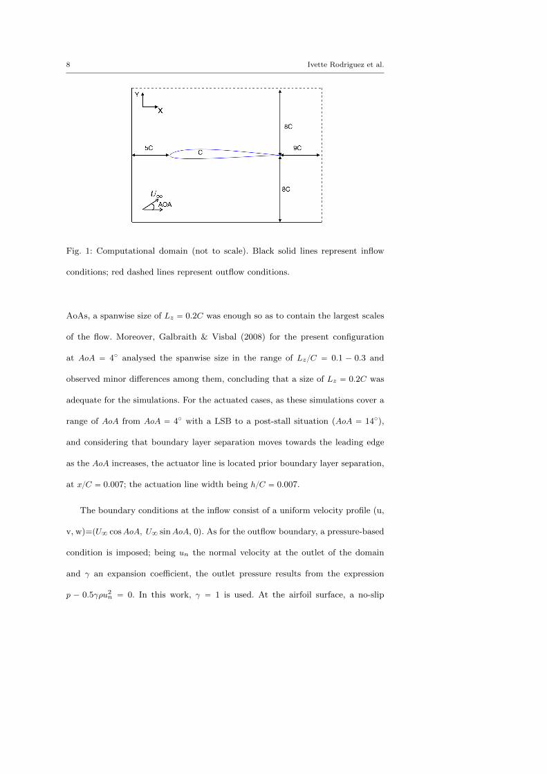
domain of dimensions 15C ˆ 16C ˆ 0.2C as is shown in figure 1. The inlet of
the domain is located at 5C from the airfoil leading edge, whereas the outlet is
placed at 9C from the airfoil trailing edge; the leading edge of the airfoil is at
px, y, zq ” p0, 0, 0q. In the spanwise direction a length of Lz “ 0.2C is used. This
size is chosen considering previous results obtained in a NACA 0012 (Rodrıguez
et al. 2013) at a comparable Re “ 5ˆ 104, where it was shown that for post-stall
8 Ivette Rodriguez et al.
Fig. 1: Computational domain (not to scale). Black solid lines represent inflow
conditions; red dashed lines represent outflow conditions.
AoAs, a spanwise size of Lz “ 0.2C was enough so as to contain the largest scales
of the flow. Moreover, Galbraith & Visbal (2008) for the present configuration
at AoA “ 4˝ analysed the spanwise size in the range of LzC “ 0.1 ´ 0.3 and
observed minor differences among them, concluding that a size of Lz “ 0.2C was
adequate for the simulations. For the actuated cases, as these simulations cover a
range of AoA from AoA “ 4˝ with a LSB to a post-stall situation (AoA “ 14˝),
and considering that boundary layer separation moves towards the leading edge
as the AoA increases, the actuator line is located prior boundary layer separation,
at xC “ 0.007; the actuation line width being hC “ 0.007.
The boundary conditions at the inflow consist of a uniform velocity profile (u,
v, w)=pU8 cosAoA, U8 sinAoA, 0q. As for the outflow boundary, a pressure-based
condition is imposed; being un the normal velocity at the outlet of the domain
and γ an expansion coefficient, the outlet pressure results from the expression
p ´ 0.5γρu2n “ 0. In this work, γ “ 1 is used. At the airfoil surface, a no-slip
Actuation on the boundary layer of an airfoil 9
condition is prescribed. Periodic boundary conditions are used in the spanwise
direction. For the actuated cases, a periodic in time and in space inlet velocity at
the outlet of the actuator line and normal to the airfoil surface is imposed as,
pu, v, wqact “ ApU8sinp2πftqsinp2πτzqpsinα, cosα, 0q (4)
Here, Ap is the maximum amplitude of the jet so as Umax “ ApU8, f is the
actuator frequency so as F` “ fU8xTE . Here, the non-dimensional frequency is
defined as in Gilarranz et al. (2005a) in terms of xTE , i.e. the x-distance from the
actuator to the trailing edge. τ is the spanwise period of the signal, in this work τ “
0.5Lz. α is the angle of the surface normal with the y-axis. The synthetic jet is also
characterised by the momentum coefficient Cµ. According to McCormick (2000), in
the range of Cµ “ 5ˆ10´4´5ˆ10´3, the increase in momentum coefficient increases
the post-stall lift; this is also in agreement with the conclusions of Goodfellow et al.
(2013) which observed that in the range of Cµ “ 3.09ˆ10´3´6.79ˆ10´3 the wake
width was reduced for AoA “ 5˝. Thus, in the present simulations, a momentum
coefficient Cµ “ 3 ˆ 10´3 is imposed. Moreover, the non-dimensional actuation
frequency is F` “ 1, for all cases.
2.2 Numerical grid
The computational meshes used are unstructured grids of about 29.94 and 30
million gridpoints for the baseline and the actuated cases, respectively. Both com-
putational meshes are similar in terms of grid resolution and only minor differences
are encountered in the zone where the actuator outlet is located. For obtaining
these meshes, an unstructured two-dimensional mesh is extruded in Nelements in
10 Ivette Rodriguez et al.
0 0.2 0.4 0.6 0.8 1
x/C
0
0.5
1
1.5
y+
AoA=4
AoA=11
AoA=14
(a)
0 0.2 0.4 0.6 0.8 1
x/C
0
2
4
6
8
x+
AoA=4
AoA=11
AoA=14
(b)
0 0.2 0.4 0.6 0.8 10
5
10
15
20
25
30
z+
AoA=4
AoA=11
AoA=14
(c)
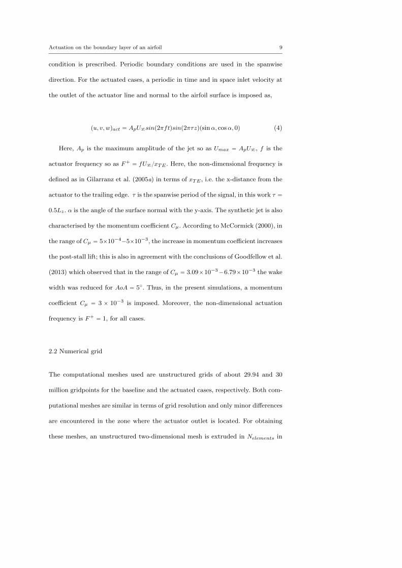
Fig. 2: Near wall grid resolution for the baseline cases. (a) Wall-normal distance
of the first grid point off the wall, y` (b) arc-length streamwise ∆x` (solid lines)
and (c) spanwise ∆z` (dashed lines) grid spacing.
the spanwise direction. The number of elements in the spanwise direction in all
computations is 64. In all cases, the meshes are constructed so as in the near
wall region the non-dimensional wall normal distance y` “ uτ ynν « 1; yn is the
wall-normal distance and uτ is defined in terms of the wall-normal shear stresses
uτ “a
τwρ. In a similar way, the arc-length streamwise ∆x` and spanwise ∆z`
resolutions are determined. In figure 2, the averaged values of the y`, ∆x` and
∆z` along the airfoil suction side for the baseline cases are plotted. Moreover, in
the near wake, i.e. 1 ď xC ď 3; ´0.4 ď yC ď 0.8, the meshes have been con-
structed clustering more gridpoints so as in this region the average ratio of the grid
size h (h ” Ω13, Ω being the cell volume) to the Kolmogorov scale (η “ pν3εq14
) is about hη « 10.8, with maximum values about phηqmax « 15. Here, to eval-
uate the local Kolmogorov length scale the turbulent kinetic energy dissipation is
approximated as ε “ 2pν ` νsgsqS1ijS1ij , S
1ij being the fluctuating strain rate.
In order to validate the current numerical set-up, the solution for the baseline
cases are compared to available solutions in the literature. For the comparison,
Actuation on the boundary layer of an airfoil 11
0 0.2 0.4 0.6 0.8 1
x/C
-1.5
-1
-0.5
0
0.5
1
1.5
Cp
(a)
0 0.2 0.4 0.6 0.8 1
x/C
-0.02
0
0.02
0.04
0.06
0.08
Cf
(b)
0.2 0.4 0.6 0.8 1
x/C
-5
-4
-3
-2
-1
0
1
2
Cp
(c)
0 0.2 0.4 0.6 0.8 1
x/C
-0.02
-0.01
0
0.01
0.02
0.03
Cf
(d)
0.2 0.4 0.6 0.8 1
x/C
-1.5
-1
-0.5
0
0.5
1
1.5
Cp
(e)
0 0.2 0.4 0.6 0.8 1
x/C
-0.02
-0.01
0
0.01
0.02
0.03
0.04
Cf
(f)
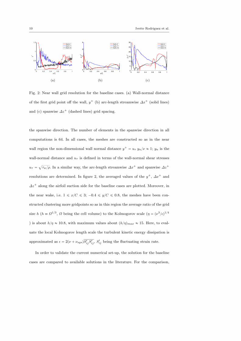
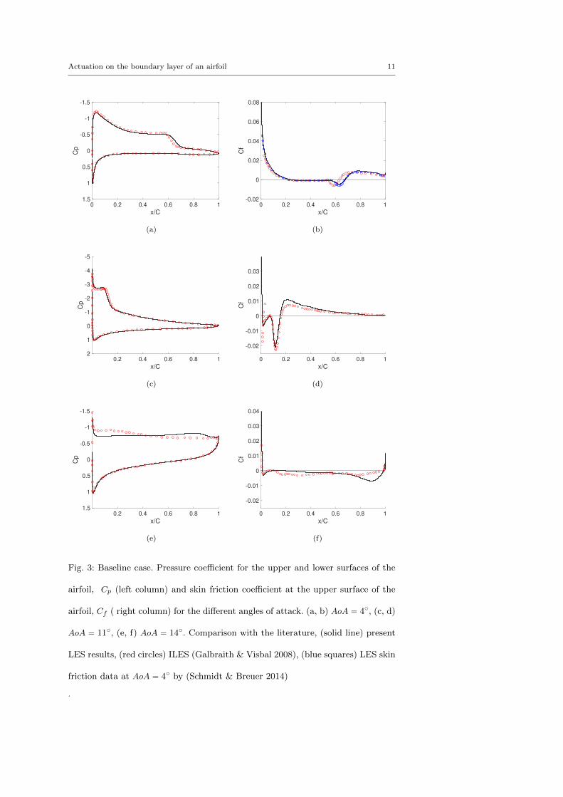
Fig. 3: Baseline case. Pressure coefficient for the upper and lower surfaces of the
airfoil, Cp (left column) and skin friction coefficient at the upper surface of the
airfoil, Cf ( right column) for the different angles of attack. (a, b) AoA “ 4˝, (c, d)
AoA “ 11˝, (e, f) AoA “ 14˝. Comparison with the literature, (solid line) present
LES results, (red circles) ILES (Galbraith & Visbal 2008), (blue squares) LES skin
friction data at AoA “ 4˝ by (Schmidt & Breuer 2014)
.
12 Ivette Rodriguez et al.
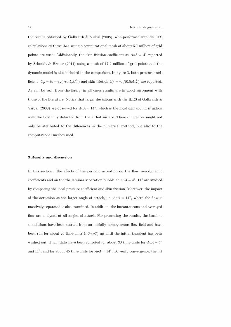
the results obtained by Galbraith & Visbal (2008), who performed implicit LES
calculations at these AoA using a computational mesh of about 5.7 million of grid
points are used. Additionally, the skin friction coefficient at AoA “ 4˝ reported
by Schmidt & Breuer (2014) using a mesh of 17.2 million of grid points and the
dynamic model is also included in the comparison. In figure 3, both pressure coef-
ficient Cp “ pp ´ p8qp0.5ρU28q and skin friction Cf “ τwp0.5ρU
28q are reported.
As can be seen from the figure, in all cases results are in good agreement with
those of the literature. Notice that larger deviations with the ILES of Galbraith &
Visbal (2008) are observed for AoA “ 14˝, which is the most demanding situation
with the flow fully detached from the airfoil surface. These differences might not
only be attributed to the differences in the numerical method, but also to the
computational meshes used.
3 Results and discussion
In this section, the effects of the periodic actuation on the flow, aerodynamic
coefficients and on the the laminar separation bubble at AoA “ 4˝, 11˝ are studied
by comparing the local pressure coefficient and skin friction. Moreover, the impact
of the actuation at the larger angle of attack, i.e. AoA “ 14˝, where the flow is
massively separated is also examined. In addition, the instantaneous and averaged
flow are analysed at all angles of attack. For presenting the results, the baseline
simulations have been started from an initially homogeneous flow field and have
been run for about 20 time-units (t U8C) up until the initial transient has been
washed out. Then, data have been collected for about 30 time-units for AoA “ 4˝
and 11˝, and for about 45 time-units for AoA “ 14˝. To verify convergence, the lift
Actuation on the boundary layer of an airfoil 13
coefficient over the last half of the averaging period has been compared to the value
over the whole simulation. Differences have been kept within 0.5% for all cases but
the baseline at AoA “ 14˝, where due to the massive separation fluctuations are
larger and thus differences are less than 3%. In order to save some computational
time, the actuated cases have been initialised from interpolated maps obtained
from the baseline cases and have been run up until the statistical stationary state
has been reached. Then, data have been collected for about 30 time-units for all
angles of attack; the results presented have been averaged both in time and in the
spanwise direction.
3.1 Effect of the actuation on the aerodynamic coefficients
To understand the effects of the actuation on the flow aerodynamic coefficients,
the characteristics of the instantaneous flow at the different angles of attack for the
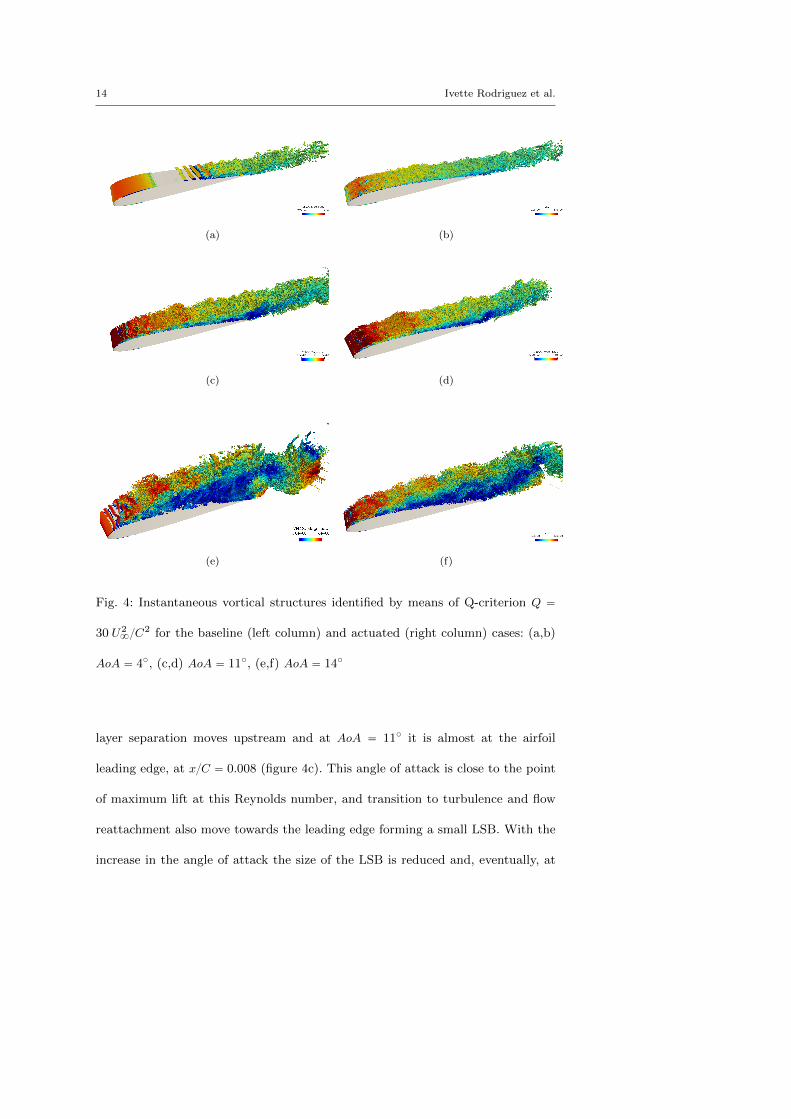
baseline and actuated cases are analysed. In figure 4, the instantaneous vortical
structures identified by means of the Q-criterion (Hunt et al. 1988) are presented.
Q-isocontours coloured by the velocity magnitude are plotted in the figure for
all cases considered. For the baseline cases, at AoA “ 4˝ (figure 4a), due to the
adverse pressure gradient the flow separates laminarly close to the leading edge of
the airfoil at about xC “ 0.24; Kelvin-Helmholtz (KH) instabilities develop in the
separated shear layer that trigger the transition to turbulence. After transition,
the shear-stresses force the flow to reattach to the airfoil surface at about xC “
0.68, thus forming a recirculation bubble also known as laminar separation bubble
(LSB). After reattachment, the fully turbulent flow travels downstream to reach
the airfoil trailing edge. As the angle of attack increases, the laminar boundary
14 Ivette Rodriguez et al.
(a) (b)
(c) (d)
(e) (f)
Fig. 4: Instantaneous vortical structures identified by means of Q-criterion Q “
30 U28C
2 for the baseline (left column) and actuated (right column) cases: (a,b)
AoA “ 4˝, (c,d) AoA “ 11˝, (e,f) AoA “ 14˝
layer separation moves upstream and at AoA “ 11˝ it is almost at the airfoil
leading edge, at xC “ 0.008 (figure 4c). This angle of attack is close to the point
of maximum lift at this Reynolds number, and transition to turbulence and flow
reattachment also move towards the leading edge forming a small LSB. With the
increase in the angle of attack the size of the LSB is reduced and, eventually, at
Actuation on the boundary layer of an airfoil 15
these Reynolds numbers the LSB burst and a drop in the lift coefficient occurs
(Sandham 2008). A further increase in the angle-of-attack, AoA “ 14˝ (figure 4e),
the flow fails to reattach to the airfoil surface forming a large separated zone, and
momentum deficit, along the suction side of the airfoil. As a result, the structures
separated from the turbulent shear layer interact with the flow coming from the
pressure side at the trailing edge shedding vortices behind the airfoil. The transient
flow and vortex shedding process that occurs at a post-stall angle was described
in detail for a NACA 0012 airfoil by Rodrıguez et al. (2013).
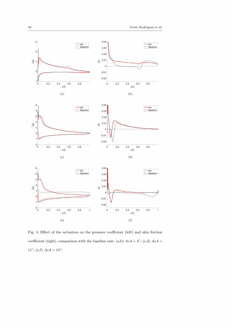
The effect of the actuation on the pressure and skin friction coefficients is de-
picted in figure 5, where a comparison with the baseline cases is also plotted. When
the periodic actuation close to the leading edge is activated, even at low angle of
attack, transition to turbulence is triggered just downstream the actuator location
(see figure 4b). Moreover, at AoA “ 4˝, the actuation succeeds at suppressing the
LSB, and thus the turbulent flow travels downstream forming an evolving turbu-
lent boundary layer. These effects can also be seen by inspecting the pressure and
skin friction profiles (see also figure 5a,b). The plateau in the pressure coefficient,
typical of a LSB, is eliminated and a gradual pressure recovery is observed instead.
Moreover a positive skin friction coefficient along the whole airfoil chord evidences
that no flow separation occur at this AoA. When the angle of attack increases
to AoA “ 11˝ (figure 4d), even though the periodic actuation early triggers the
transition to turbulence, the adverse pressure gradient forces the flow to separate;
as a consequence a small recirculation zone is formed, but its smaller than the
LSB formed at this angle-of-attack for the baseline case. The turbulent flow reat-
tachment moves from xC “ 0.15 to xC “ 0.09 when the flow actuation is used
16 Ivette Rodriguez et al.
0 0.2 0.4 0.6 0.8
x/C
-3
-2
-1
0
1
Cp
Act
Baseline
(a)
0 0.2 0.4 0.6 0.8
x/C
-0.02
-0.01
0
0.01
0.02
0.03
0.04
Cf
Act
Baseline
(b)
0 0.2 0.4 0.6 0.8
x/C
-5
-4
-3
-2
-1
0
1
2
Cp
Act
Baseline
(c)
0 0.2 0.4 0.6 0.8
x/C
-0.02
-0.01
0
0.01
0.02
0.03
0.04
Cf
Act
Baseline
(d)
0 0.2 0.4 0.6 0.8 1
x/C
-5
-4
-3
-2
-1
0
1
2
Cp
Act
Baseline
(e)
0 0.2 0.4 0.6 0.8 1
x/C
-0.02
-0.01
0
0.01
0.02
0.03
0.04
Cf
Act
Baseline
(f)
Fig. 5: Effect of the actuation on the pressure coefficient (left) and skin friction
coefficient (right), comparison with the baseline case. (a,b) AoA “ 4˝; (c,d) AoA “
11˝; (e,f) AoA “ 14˝;
Actuation on the boundary layer of an airfoil 17
0 5 10 15
AoA[deg]
0.2
0.4
0.6
0.8
1
1.2
CL
Exp95
Exp 89
ILES
Present LES
Present LES act
(a)
0 5 10 15
AoA[deg]
0
0.05
0.1
0.15
0.2
0.25
0.3
CD
Exp 89
Exp 95
ILES
Present LES
Present LES act
(b)
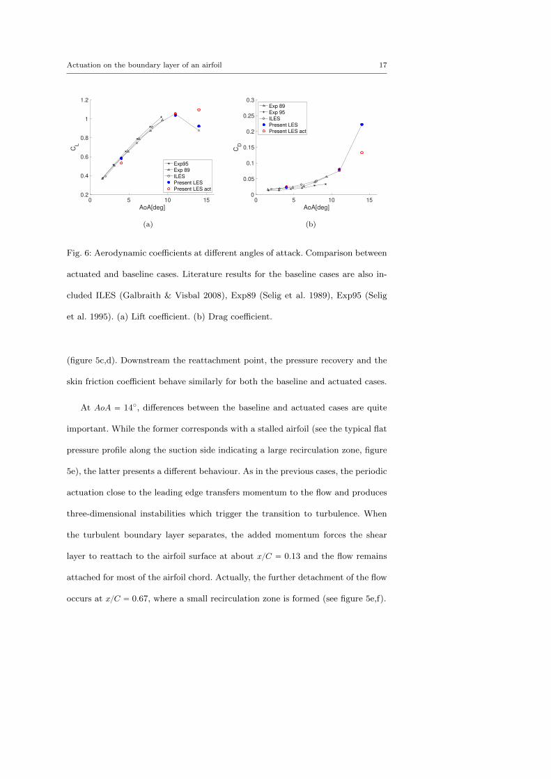
Fig. 6: Aerodynamic coefficients at different angles of attack. Comparison between
actuated and baseline cases. Literature results for the baseline cases are also in-
cluded ILES (Galbraith & Visbal 2008), Exp89 (Selig et al. 1989), Exp95 (Selig
et al. 1995). (a) Lift coefficient. (b) Drag coefficient.
(figure 5c,d). Downstream the reattachment point, the pressure recovery and the
skin friction coefficient behave similarly for both the baseline and actuated cases.
At AoA “ 14˝, differences between the baseline and actuated cases are quite
important. While the former corresponds with a stalled airfoil (see the typical flat
pressure profile along the suction side indicating a large recirculation zone, figure
5e), the latter presents a different behaviour. As in the previous cases, the periodic
actuation close to the leading edge transfers momentum to the flow and produces
three-dimensional instabilities which trigger the transition to turbulence. When
the turbulent boundary layer separates, the added momentum forces the shear
layer to reattach to the airfoil surface at about xC “ 0.13 and the flow remains
attached for most of the airfoil chord. Actually, the further detachment of the flow
occurs at xC “ 0.67, where a small recirculation zone is formed (see figure 5e,f).
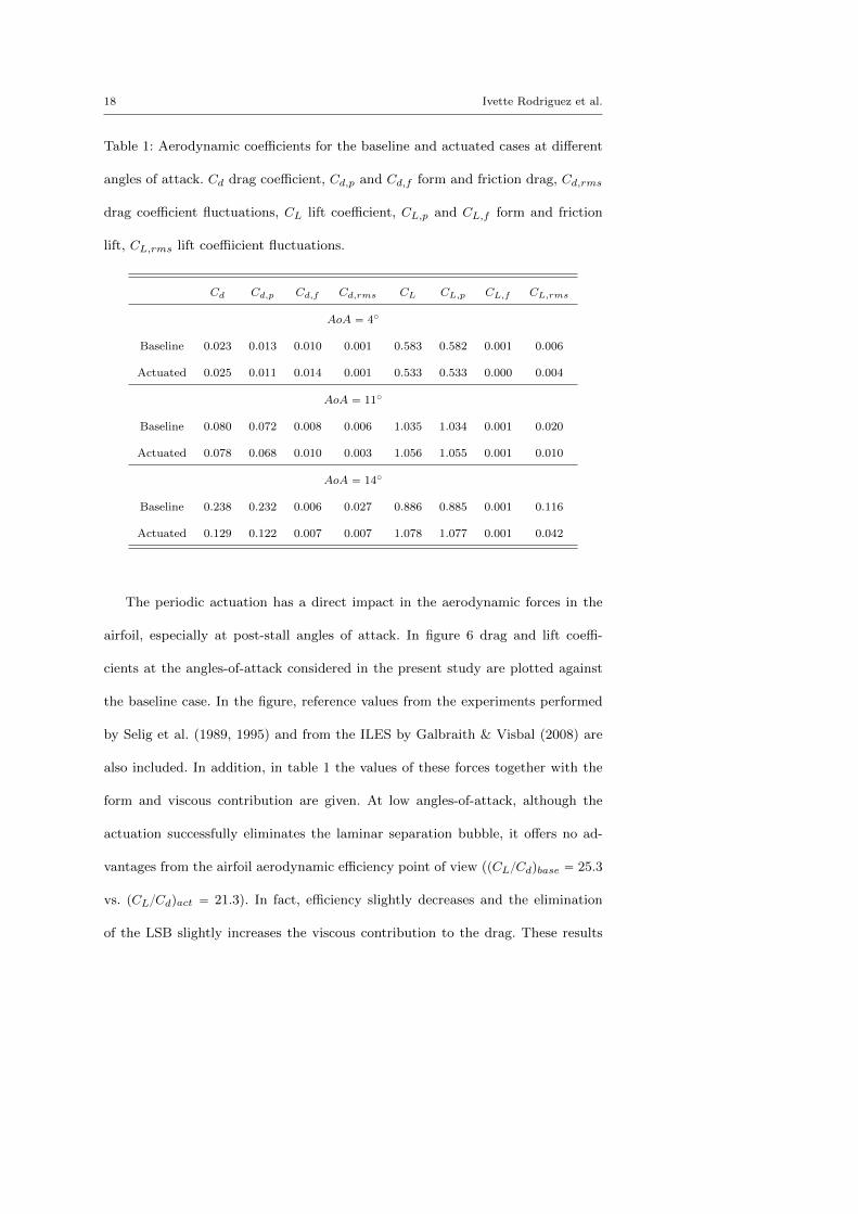
18 Ivette Rodriguez et al.
Table 1: Aerodynamic coefficients for the baseline and actuated cases at different
angles of attack. Cd drag coefficient, Cd,p and Cd,f form and friction drag, Cd,rms
drag coefficient fluctuations, CL lift coefficient, CL,p and CL,f form and friction
lift, CL,rms lift coeffiicient fluctuations.
Cd Cd,p Cd,f Cd,rms CL CL,p CL,f CL,rms
AoA “ 4˝
Baseline 0.023 0.013 0.010 0.001 0.583 0.582 0.001 0.006
Actuated 0.025 0.011 0.014 0.001 0.533 0.533 0.000 0.004
AoA “ 11˝
Baseline 0.080 0.072 0.008 0.006 1.035 1.034 0.001 0.020
Actuated 0.078 0.068 0.010 0.003 1.056 1.055 0.001 0.010
AoA “ 14˝
Baseline 0.238 0.232 0.006 0.027 0.886 0.885 0.001 0.116
Actuated 0.129 0.122 0.007 0.007 1.078 1.077 0.001 0.042
The periodic actuation has a direct impact in the aerodynamic forces in the
airfoil, especially at post-stall angles of attack. In figure 6 drag and lift coeffi-
cients at the angles-of-attack considered in the present study are plotted against
the baseline case. In the figure, reference values from the experiments performed
by Selig et al. (1989, 1995) and from the ILES by Galbraith & Visbal (2008) are
also included. In addition, in table 1 the values of these forces together with the
form and viscous contribution are given. At low angles-of-attack, although the
actuation successfully eliminates the laminar separation bubble, it offers no ad-
vantages from the airfoil aerodynamic efficiency point of view (pCLCdqbase “ 25.3
vs. pCLCdqact “ 21.3). In fact, efficiency slightly decreases and the elimination
of the LSB slightly increases the viscous contribution to the drag. These results
Actuation on the boundary layer of an airfoil 19
are in disagreement with the observations of Goodfellow et al. (2013) for a NACA
0025 at AoA “ 5˝, who found that the actuation reduces the drag and the wake
width behind the airfoil. However, this apparently contradictory result might be
related with the airfoil design. NACA 0025 is a thick symmetric airfoil with trailing
edge separation, whereas SD7003 is a cambered airfoil especially designed to have
a shallow LSB with leading edge separation. In fact, Selig et al. (1989) pointed
out that SD7003 airfoil was designed so as to have a LSB with a gradual pressure
recovery. Thus, for this design the elimination of the LSB produces no benefit
from the drag point of view. This is also in agreement with the Selig et al. (1989)
experimental results in which they observed that tripping the boundary layer and
triggering transition did not reduce the airfoil drag.
Conversely, at post-stall angle of attack AoA “ 14˝, the benefits from the actu-
ation are very clear. It retards the stall by eliminating the large recirculation zone
and promoting the flow reattachment, and as a consequence, the lift coefficient
increases by 22%, whereas the reduction in the drag forces is about 46%, thus
increasing the airfoil aerodynamic efficiency by 124%. Moreover, the actuation re-
duces the fluctuations in both lift and drag forces at all AoAs. This is specially
interesting at the larger AoA as the transient flow is dominated by the shedding
of vortices. When the periodic actuation is active, and as a consequence of the
flow reattachment, fluctuations are reduced by a 74% and 64% in the drag and lift
forces, respectively.
20 Ivette Rodriguez et al.
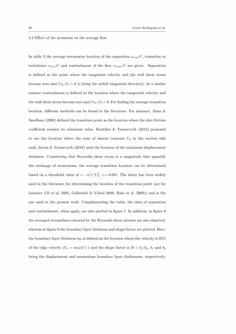
3.2 Effect of the actuation on the average flow
In table 2 the average streamwise location of the separation xsepC, transition to
turbulence xtraC and reattachment of the flow xreatC are given. Separation
is defined as the point where the tangential velocity and the wall shear stress
become zero and BτwBs ă 0 (s being the airfoil tangential direction). In a similar
manner reattachment is defined as the location where the tangential velocity and
the wall shear stress become zero and BτwBs ą 0. For finding the average transition
location, different methods can be found in the literature. For instance, Alam &
Sandham (2000) defined the transition point as the location where the skin friction
coefficient reaches its minimum value. Boutilier & Yarusevych (2012) proposed
to use the location where the zone of almost constant Cp in the suction side
ends. Istvan & Yarusevych (2018) used the location of the maximum displacement
thickness. Considering that Reynolds shear stress is a magnitude that quantify
the exchange of momentum, the average transition location can be determined
based on a threshold value of ă ´u1v1U28 ą“ 0.001. The latter has been widely
used in the literature for determining the location of the transition point (see for
instance (Ol et al. 2005, Galbraith & Visbal 2008, Hain et al. 2009)) and is the
one used in the present work. Complementing the table, the data of separation
and reattachment, when apply, are also plotted in figure 7. In addition, in figure 8
the averaged streamlines coloured by the Reynolds shear stresses are also depicted,
whereas in figure 9 the boundary layer thickness and shape factor are plotted. Here,
the boundary layer thickness δ95 is defined as the location where the velocity is 95%
of the edge velocity (Ue “ maxpUq ) and the shape factor is H “ δ1δ2, δ1 and δ2
being the displacement and momentum boundary layer thicknesses, respectively;
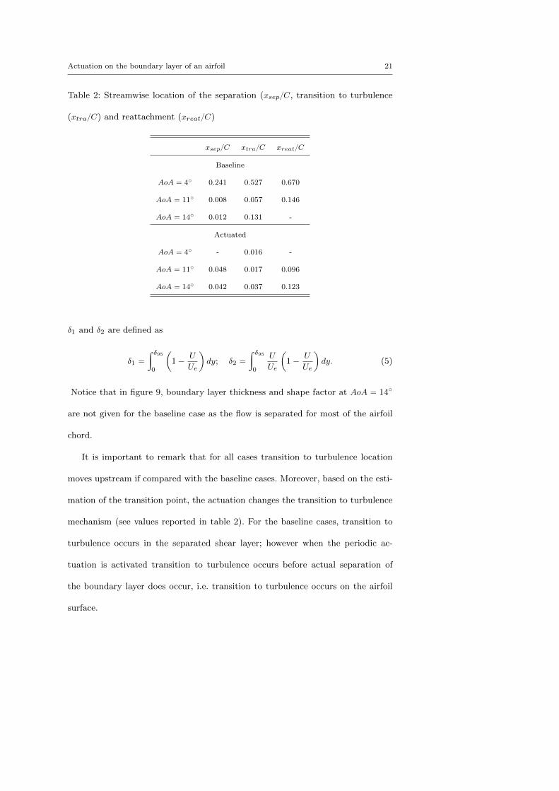
Actuation on the boundary layer of an airfoil 21
Table 2: Streamwise location of the separation (xsepC, transition to turbulence
(xtraC) and reattachment (xreatC)
xsepC xtraC xreatC
Baseline
AoA “ 4˝ 0.241 0.527 0.670
AoA “ 11˝ 0.008 0.057 0.146
AoA “ 14˝ 0.012 0.131 -
Actuated
AoA “ 4˝ - 0.016 -
AoA “ 11˝ 0.048 0.017 0.096
AoA “ 14˝ 0.042 0.037 0.123
δ1 and δ2 are defined as
δ1 “
ż δ95
0
ˆ
1´U
Ue
˙
dy; δ2 “
ż δ95
0
U
Ue
ˆ
1´U
Ue
˙
dy. (5)
Notice that in figure 9, boundary layer thickness and shape factor at AoA “ 14˝
are not given for the baseline case as the flow is separated for most of the airfoil
chord.
It is important to remark that for all cases transition to turbulence location
moves upstream if compared with the baseline cases. Moreover, based on the esti-
mation of the transition point, the actuation changes the transition to turbulence
mechanism (see values reported in table 2). For the baseline cases, transition to
turbulence occurs in the separated shear layer; however when the periodic ac-
tuation is activated transition to turbulence occurs before actual separation of
the boundary layer does occur, i.e. transition to turbulence occurs on the airfoil
surface.
22 Ivette Rodriguez et al.
0 0.2 0.4 0.6 0.8 1
x/C
0
2
4
6
8
10
12
14
16
18
AoA
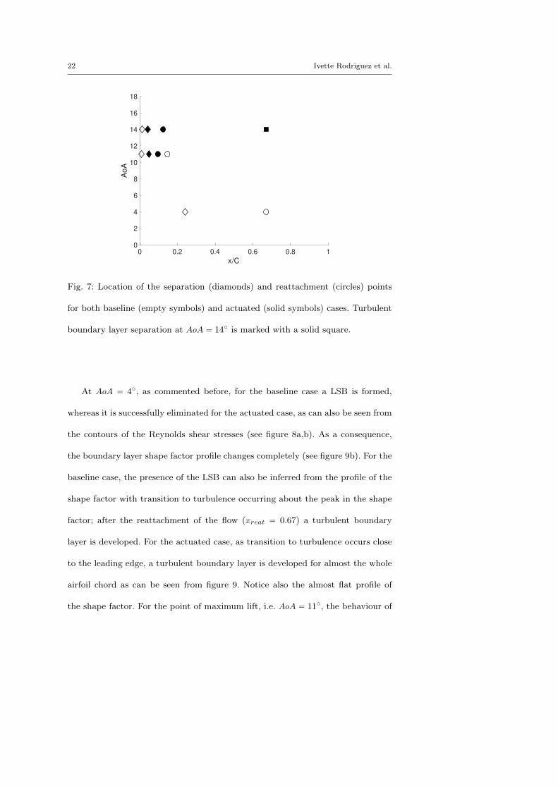
Fig. 7: Location of the separation (diamonds) and reattachment (circles) points
for both baseline (empty symbols) and actuated (solid symbols) cases. Turbulent
boundary layer separation at AoA “ 14˝ is marked with a solid square.
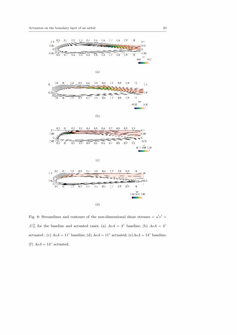
At AoA “ 4˝, as commented before, for the baseline case a LSB is formed,
whereas it is successfully eliminated for the actuated case, as can also be seen from
the contours of the Reynolds shear stresses (see figure 8a,b). As a consequence,
the boundary layer shape factor profile changes completely (see figure 9b). For the
baseline case, the presence of the LSB can also be inferred from the profile of the
shape factor with transition to turbulence occurring about the peak in the shape
factor; after the reattachment of the flow (xreat “ 0.67) a turbulent boundary
layer is developed. For the actuated case, as transition to turbulence occurs close
to the leading edge, a turbulent boundary layer is developed for almost the whole
airfoil chord as can be seen from figure 9. Notice also the almost flat profile of
the shape factor. For the point of maximum lift, i.e. AoA “ 11˝, the behaviour of
Actuation on the boundary layer of an airfoil 23
(a)
(b)
(c)
(d)
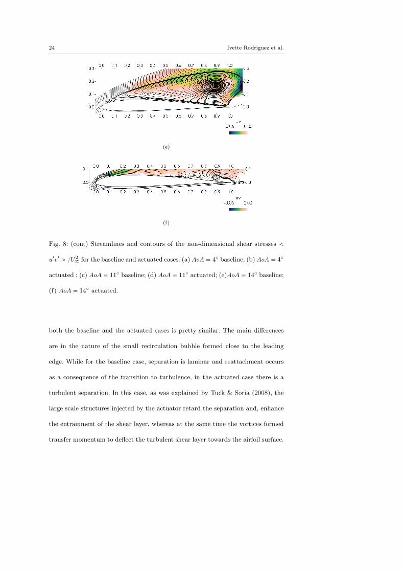
Fig. 8: Streamlines and contours of the non-dimensional shear stresses ă u1v1 ą
U28 for the baseline and actuated cases. (a) AoA “ 4˝ baseline; (b) AoA “ 4˝
actuated ; (c) AoA “ 11˝ baseline; (d) AoA “ 11˝ actuated; (e)AoA “ 14˝ baseline;
(f) AoA “ 14˝ actuated.
24 Ivette Rodriguez et al.
(e)
(f)
Fig. 8: (cont) Streamlines and contours of the non-dimensional shear stresses ă
u1v1 ą U28 for the baseline and actuated cases. (a) AoA “ 4˝ baseline; (b) AoA “ 4˝
actuated ; (c) AoA “ 11˝ baseline; (d) AoA “ 11˝ actuated; (e)AoA “ 14˝ baseline;
(f) AoA “ 14˝ actuated.
both the baseline and the actuated cases is pretty similar. The main differences
are in the nature of the small recirculation bubble formed close to the leading
edge. While for the baseline case, separation is laminar and reattachment occurs
as a consequence of the transition to turbulence, in the actuated case there is a
turbulent separation. In this case, as was explained by Tuck & Soria (2008), the
large scale structures injected by the actuator retard the separation and, enhance
the entrainment of the shear layer, whereas at the same time the vortices formed
transfer momentum to deflect the turbulent shear layer towards the airfoil surface.
Actuation on the boundary layer of an airfoil 25
As a result, a smaller recirculation is formed on the airfoil surface. Notice also that
the profile of the shape factor changes in the separated zone, but after separation
the boundary layer of both the actuated and the baseline cases behaves in a similar
manner.
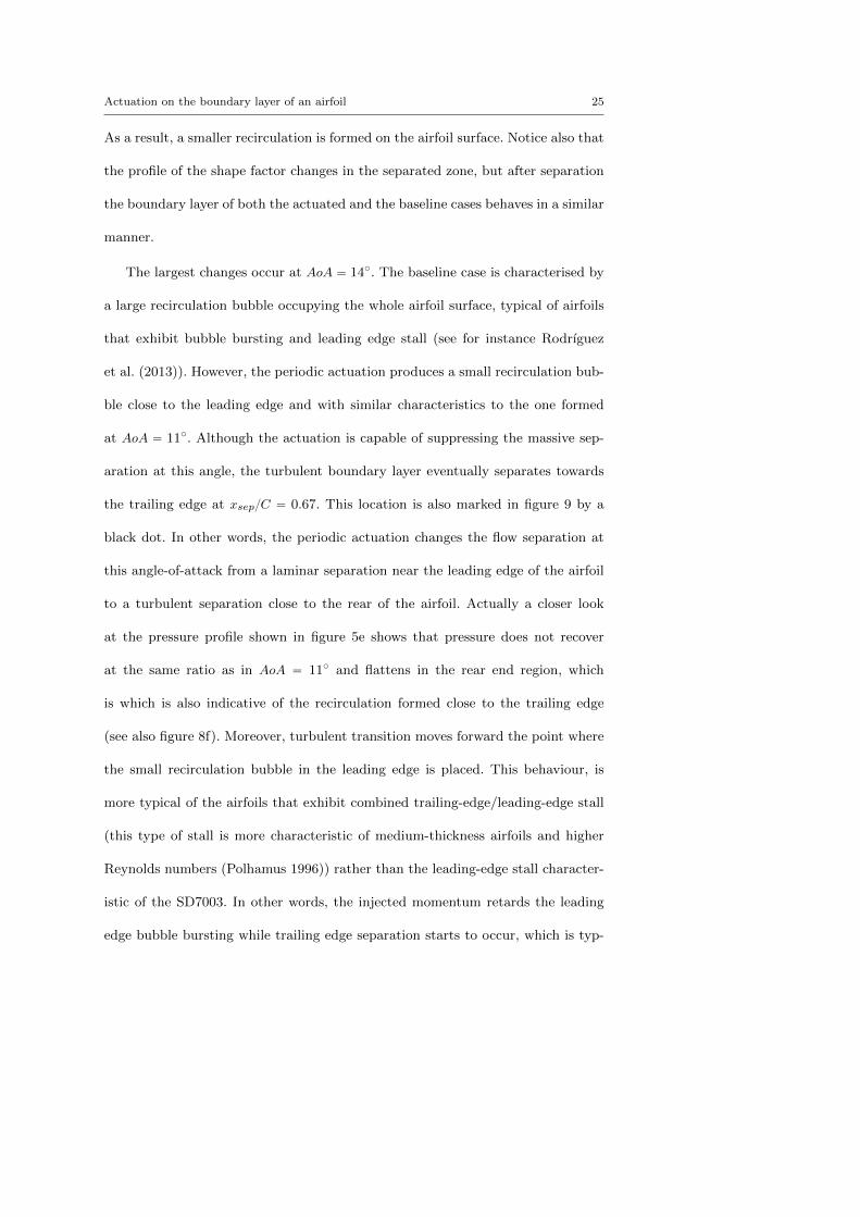
The largest changes occur at AoA “ 14˝. The baseline case is characterised by
a large recirculation bubble occupying the whole airfoil surface, typical of airfoils
that exhibit bubble bursting and leading edge stall (see for instance Rodrıguez
et al. (2013)). However, the periodic actuation produces a small recirculation bub-
ble close to the leading edge and with similar characteristics to the one formed
at AoA “ 11˝. Although the actuation is capable of suppressing the massive sep-
aration at this angle, the turbulent boundary layer eventually separates towards
the trailing edge at xsepC “ 0.67. This location is also marked in figure 9 by a
black dot. In other words, the periodic actuation changes the flow separation at
this angle-of-attack from a laminar separation near the leading edge of the airfoil
to a turbulent separation close to the rear of the airfoil. Actually a closer look
at the pressure profile shown in figure 5e shows that pressure does not recover
at the same ratio as in AoA “ 11˝ and flattens in the rear end region, which
is which is also indicative of the recirculation formed close to the trailing edge
(see also figure 8f). Moreover, turbulent transition moves forward the point where
the small recirculation bubble in the leading edge is placed. This behaviour, is
more typical of the airfoils that exhibit combined trailing-edge/leading-edge stall
(this type of stall is more characteristic of medium-thickness airfoils and higher
Reynolds numbers (Polhamus 1996)) rather than the leading-edge stall character-
istic of the SD7003. In other words, the injected momentum retards the leading
edge bubble bursting while trailing edge separation starts to occur, which is typ-
26 Ivette Rodriguez et al.
0 0.2 0.4 0.6 0.8 1
X/C
0
0.05
0.1
0.15
0.2
0.25
0.3
0.35
95/C
AoA=4
AoA=11
AoA=14
(a)
0.2 0.4 0.6 0.8 1
X/C
0
5
10
15
20
25
30
35
H
AoA=4
AoA=11
AoA=14
(b)
Fig. 9: (a) Boundary layer thickness and (b) shape factor for the actuated cases.
Comparison for the different angles of attack. The solid dot represents the bound-
ary layer separation for the actuated case at AoA “ 14˝. Baseline cases (dashed
lines), actuated cases (solid lines).
ical of the trailing-edge/leading edge type of stall. It is conjectured that if the
angle-of-attack is further increased, the recirculation zone will move towards the
leading edge and, eventually, when it approaches about airfoil mid-chord it will
reach the new maximum lift angle.
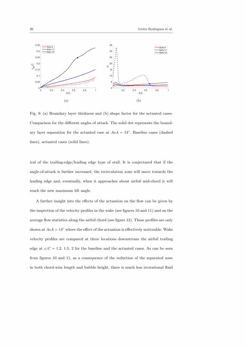
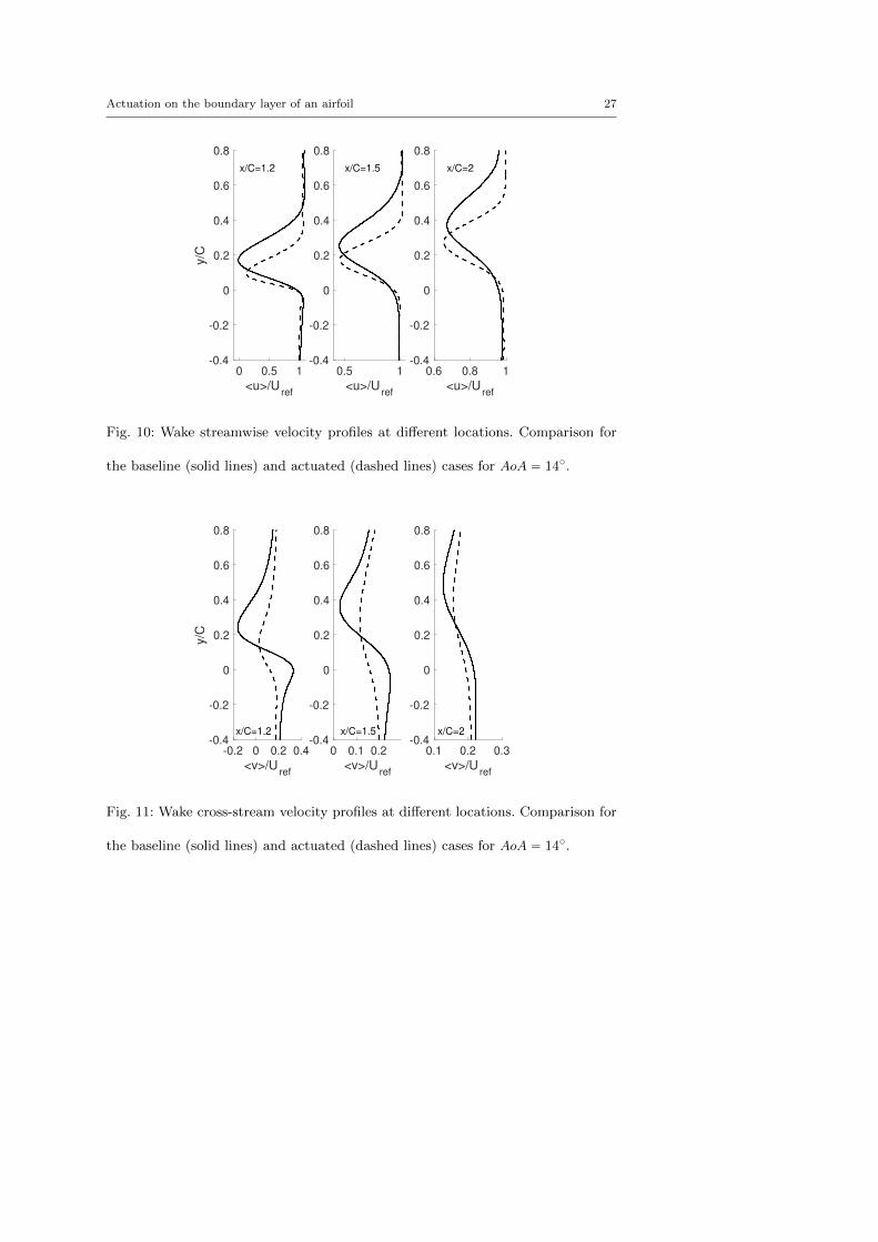
A further insight into the effects of the actuation on the flow can be given by
the inspection of the velocity profiles in the wake (see figures 10 and 11) and on the
average flow statistics along the airfoil chord (see figure 12). These profiles are only
shown at AoA “ 14˝ where the effect of the actuation is effectively noticeable. Wake
velocity profiles are compared at three locations downstream the airfoil trailing
edge at xC “ 1.2, 1.5, 2 for the baseline and the actuated cases. As can be seen
from figures 10 and 11, as a consequence of the reduction of the separated zone
in both chord-wise length and bubble height, there is much less irrotational fluid
Actuation on the boundary layer of an airfoil 27
0 0.5 1
<u>/Uref
-0.4
-0.2
0
0.2
0.4
0.6
0.8
y/C
x/C=1.2
0.5 1
<u>/Uref
-0.4
-0.2
0
0.2
0.4
0.6
0.8
x/C=1.5
0.6 0.8 1
<u>/Uref
-0.4
-0.2
0
0.2
0.4
0.6
0.8
x/C=2
Fig. 10: Wake streamwise velocity profiles at different locations. Comparison for
the baseline (solid lines) and actuated (dashed lines) cases for AoA “ 14˝.
-0.2 0 0.2 0.4
<v>/Uref
-0.4
-0.2
0
0.2
0.4
0.6
0.8
y/C
x/C=1.2
0 0.1 0.2
<v>/Uref
-0.4
-0.2
0
0.2
0.4
0.6
0.8
x/C=1.5
0.1 0.2 0.3
<v>/Uref
-0.4
-0.2
0
0.2
0.4
0.6
0.8
x/C=2
Fig. 11: Wake cross-stream velocity profiles at different locations. Comparison for
the baseline (solid lines) and actuated (dashed lines) cases for AoA “ 14˝.
28 Ivette Rodriguez et al.
entrainment, the wake width is reduced and the maximum velocity deficit is moved
downwards towards lower yC values. This is also indicative of the reduction in
the drag achieved (see also figure 6b).
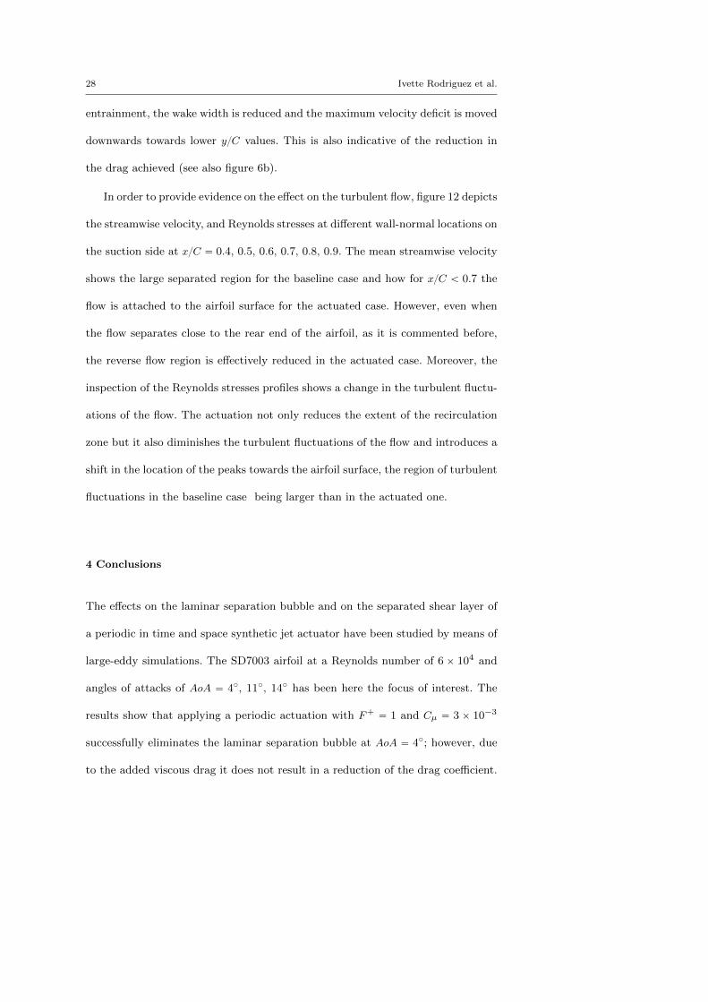
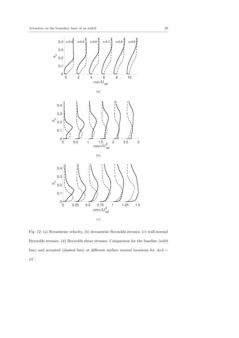
In order to provide evidence on the effect on the turbulent flow, figure 12 depicts
the streamwise velocity, and Reynolds stresses at different wall-normal locations on
the suction side at xC “ 0.4, 0.5, 0.6, 0.7, 0.8, 0.9. The mean streamwise velocity
shows the large separated region for the baseline case and how for xC ă 0.7 the
flow is attached to the airfoil surface for the actuated case. However, even when
the flow separates close to the rear end of the airfoil, as it is commented before,
the reverse flow region is effectively reduced in the actuated case. Moreover, the
inspection of the Reynolds stresses profiles shows a change in the turbulent fluctu-
ations of the flow. The actuation not only reduces the extent of the recirculation
zone but it also diminishes the turbulent fluctuations of the flow and introduces a
shift in the location of the peaks towards the airfoil surface, the region of turbulent
fluctuations in the baseline case being larger than in the actuated one.
4 Conclusions
The effects on the laminar separation bubble and on the separated shear layer of
a periodic in time and space synthetic jet actuator have been studied by means of
large-eddy simulations. The SD7003 airfoil at a Reynolds number of 6 ˆ 104 and
angles of attacks of AoA “ 4˝, 11˝, 14˝ has been here the focus of interest. The
results show that applying a periodic actuation with F` “ 1 and Cµ “ 3 ˆ 10´3
successfully eliminates the laminar separation bubble at AoA “ 4˝; however, due
to the added viscous drag it does not result in a reduction of the drag coefficient.
Actuation on the boundary layer of an airfoil 29
0 2 4 6 8 10
<u>/Uref
0
0.1
0.2
0.3
0.4
yn
x=0.4 x=0.5 x=0.6 x=0.7 x=0.8 x=0.9
(a)
0 0.5 1 1.5 2 2.5 3<uu>/U
2
ref
0
0.1
0.2
0.3
0.4
yn
(b)
0 0.25 0.5 0.75 1 1.25 1.5
<vv>/U2
ref
0
0.1
0.2
0.3
0.4
yn
(c)
Fig. 12: (a) Streamwise velocity, (b) streamwise Reynolds stresses, (c) wall-normal
Reynolds stresses, (d) Reynolds shear stresses. Comparison for the baseline (solid
line) and actuated (dashed line) at different surface normal locations for AoA “
14˝.
30 Ivette Rodriguez et al.
0 0.05 0.1 0.15 0.2 0.25
<uv>/U2
ref
0
0.1
0.2
0.3
0.4
yn
(d)
Fig. 12: (a) Streamwise velocity, (b) streamwise Reynolds stresses, (c) wall-normal
Reynolds stresses, (d) Reynolds shear stresses. Comparison for the baseline (solid
line) and actuated (dashed line) at different surface normal locations for AoA “
14˝.
In terms of airfoil aerodynamic efficiency, the actuation is only effective at angles
of attack larger than the point of maximum lift, where it eliminates the massive
flow separation and delays the airfoil stall. At AoA “ 14˝, the periodic actuation
suppresses the large recirculation and forces the shear layer to reattach to the airfoil
surface, and as a consequence, it also increases the airfoil lift by 22% and reduces
the drag by 46% resulting in an increase in the airfoil aerodynamic efficiency by a
124%.
Important effects on the flow are also observed. As a consequence of the actua-
tion, the transition to turbulence mechanism changes from a KH instability in the
separated shear layer to occur right after the actuator outlet on the airfoil surface.
It is also shown that at larger angles of attack, the reduction in the separated flow
decreases the wake width, which is also indicative of the drag reduction, displacing
Actuation on the boundary layer of an airfoil 31
the maximum velocity deficit towards lower yC values, and decreases the turbu-
lent fluctuations of the flow. Moreover, the injected momentum produces a small
recirculation bubble close to the airfoil leading edge and retards separation of the
boundary layer at larger angles of attack. Thus, turbulent separation occurs close
to the rear end of the airfoil, with a recirculation zone that flattens the pressure
profile. It is conjectured that the combination of the small recirculation bubble
in the leading edge with the turbulent boundary layer separation past airfoil mid-
chord might lead to a trailing-edge/leading-edge type of stall at larger angles of
attack. Thus, it is suggested that the actuation changes the nature of the stall to
a trailing-edge/leading-edge stall more typical of medium-thickness airfoils rather
than the leading-edge type of stall of the SD7003.
Compliance with Ethical Standards
The authors declare that they have no conflict of interest.
Acknowledgments
This work has been partially financially supported by the Ministerio de Economıa
y Competitividad, Secretarıa de Estado de Investigacion, Desarrollo e Innovacion,
Spain (Ref. TRA2017-88508-R) and by European Union’s Horizon 2020 research
and innovation programme (INFRAEDI-02-2018, EXCELLERAT- The European
Centre Of Excellence For Engineering Applications H2020.). We also acknowl-
edge Red Espanola de Surpercomputacion (RES) for awarding us access to the
MareNostrum IV machine based in Barcelona, Spain (Ref. FI-2018-2-0015 and
32 Ivette Rodriguez et al.
FI-2018-3-0021).This work is also funded in part by the Coturb program of the
European Research Council.
References
Akbarzadeh, A. & Borazjani, I. (2019), A numerical study on controlling flow
separation via surface morphing in the form of backward traveling waves, in
‘AIAA Aviation Forum’, pp. 1–11.
Alam, M. & Sandham, N. (2000), ‘Direct numerical simulation of short separation
bubbles with turbulent reattachment’, Journal of Fluid Mechanics 410, 1–28.
Albers, M., Meysonnat, P. S. & Schroder, W. (2019), ‘Actively Reduced Air-
foil Drag by Transversal Surface Waves’, Flow, Turbulence and Combustion
102(4), 865–886.
Amitay, M. & Glezer, a. (2002), ‘Role of actuation frequency in controlled flow
reattachment over a stalled airfoil’, AIAA Journal 40(2), 209–216.
Amitay, M., Smith, D. R., Kibens, V., Parekh, D. E. & Glezer, A. (2001), ‘Aerody-
namic flow control over an unconventional airfoil using synthetic jet actuators’,
AIAA journal 39(3), 361–370.
Atzori, M., Vinuesa, R., Stroh, A., B.Frohnapfel & Schlatter., P. (2018), As-
sessment of skin-friction-reduction techniques on a turbulent wing section, in
‘ETMM-12 2018’.
Boutilier, M. S. H. & Yarusevych, S. (2012), ‘Parametric study of separation and
transition characteristics over an airfoil at low Reynolds numbers’, Experiments
in Fluids 52(6), 1491–1506.
Actuation on the boundary layer of an airfoil 33
Buchmann, N. A., Atkinson, C. & Soria, J. (2013), ‘Influence of ZNMF jet flow
control on the spatio-temporal flow structure over a NACA-0015 airfoil’, Exper-
iments in Fluids 54(3).
Calmet, H., Gambaruto, A. M., Bates, A. J., Vazquez, M., Houzeaux, G. & Doorly,
D. J. (2016), ‘Large-scale CFD simulations of the transitional and turbulent
regime for the large human airways during rapid inhalation’, Computers in biology
and medicine 69(1), 166–180.
Cattafesta, L. N. & Sheplak, M. (2011), ‘Actuators for Active Flow Control’,
Annual Review of Fluid Mechanics 43(1), 247–272.
Charnyi, S., Heister, T., Olshanskii, M. A. & Rebholz, L. G. (2017), ‘On conser-
vation laws of navier-stokes galerkin discretizations’, J. Comput. Phys. 337, 289
– 308.
Choi, K. S., Timothy, J. & Whalley, R. (2011), ‘Turbulent boundary-layer con-
trol with plasma actuators’, Philosophical Transactions of the Royal Society A:
Mathematical, Physical and Engineering Sciences 369(1940), 1443–1458.
Codina, R. (2001), ‘Pressure stability in fractional step finite element methods for
incompressible flows’, J. Comput. Phys. 130(1), 112–140.
Duvigneau, R. & Visonneau, M. (2006), ‘Optimization of a synthetic jet actuator
for aerodynamic stall control’, Computers and Fluids 35(6), 624–638.
Eto, K., Kondo, Y., Fukagata, K. & Tokugawa, N. (2018), Friction Drag Reduction
on a Clark-Y Airfoil Using Uniform Blowing.
URL: https://arc.aiaa.org/doi/abs/10.2514/6.2018-3374
Galbraith, M. & Visbal, M. (2008), ‘Implicit Large Eddy Simulation of Low
Reynolds Number Flow Past the SD7003 Airfoil’, 46th AIAA Aerospace Sciences
Meeting and Exhibit (January), 1–17.
34 Ivette Rodriguez et al.
Gilarranz, J. L., Traub, L. W. & Rediniotis, O. K. (2005a), ‘A New Class of
Synthetic Jet Actuators—Part I: Design, Fabrication and Bench Top Charac-
terization’, Journal of Fluids Engineering 127(2), 367.
Gilarranz, J. L., Traub, L. W. & Rediniotis, O. K. (2005b), ‘A New Class of Syn-
thetic Jet Actuators—Part II: Application to Flow Separation Control’, Journal
of Fluids Engineering 127(2), 377.
Glezer, A. (2011), ‘Some aspects of aerodynamic flow control using synthetic-
jet actuation’, Philosophical Transactions of the Royal Society A: Mathematical,
Physical and Engineering Sciences 369(1940), 1476–1494.
URL: http://rsta.royalsocietypublishing.org/cgi/doi/10.1098/rsta.2010.0374
Goodfellow, S. D., Yarusevych, S. & Sullivan, P. E. (2013), ‘Momentum coefficient
as a parameter for aerodynamic flow control with synthetic jets’, AIAA Journal
51(3), 623–631.
Govert, S., Mira, D., Zavala-Ake, M., Kok, J., Vazquez, M. & Houzeaux, G. (2017),
‘Heat loss prediction of a confined premixed jet flame using a conjugate heat
transfer approach’, International Journal of Heat and Mass Transfer 107, 882 –
894.
Hain, R., Kahler, C. J. & Radespiel, R. (2009), ‘Dynamics of laminar separation
bubbles at low-Reynolds-number aerofoils’, Journal of Fluid Mechanics 630, 129–
153.
Huang, L., Huang, P. G., LeBeau, R. P. & Hauser, T. (2004), ‘Numerical study of
blowing and suction control mechanism on NACA0012 airfoil’, Journal of Aircraft
41(5), 1005–1013.
Hunt, J., Wray, A. & Moin, P. (1988), Eddies, stream and convergence zones in
turbulent flows, Technical Report CTR-S88, Center for turbulent research.
Actuation on the boundary layer of an airfoil 35
Istvan, M. S. & Yarusevych, S. (2018), ‘Effects of free-stream turbulence intensity
on transition in a laminar separation bubble formed over an airfoil’, Experiments
in Fluids 59(3), 1–21.
URL: http://dx.doi.org/10.1007/s00348-018-2511-6
Kim, J., Moin, P. & Seifert, A. (2017), ‘Large-eddy simulation-based charac-
terization of suction and oscillatory blowing fluidic actuator’, AIAA Journal
55(8), 2566–2579.
Kitsios, V., Cordier, L., Bonnet, J.-P., Ooi, a. & Soria, J. (2011), ‘On the coher-
ent structures and stability properties of a leading-edge separated aerofoil with
turbulent recirculation’, Journal of Fluid Mechanics 683(2011), 395–416.
Lehmkuhl, O., Houzeaux, G., Owen, H., Chrysokentis, G. & Rodriguez, I. (2019),
‘A low-dissipation finite element scheme for scale resolving simulations of tur-
bulent flows’, Journal of Computational Physics 390, 51–65.
Liu, P. Q., Duan, H. S., Chen, J. Z. & He, Y. W. (2010), ‘Numerical study
of suction-blowing flow control technology for an airfoil’, Journal of Aircraft
47(1), 229–239.
McCormick, D. C. (2000), Boundary Layer Separation control with Directed Syn-
thetic Jets, in ‘38th Aerospace Sciences Meeting & Exhibit’, number AIAA
2000-0519.
Mira, D., Zavala-Ake, M., Avila, M., Owen, H., Cajas, J. C., Vazquez, M. &
Houzeaux, G. (2016), ‘Heat transfer effects on a fully premixed methane im-
pinging flame’, Flow, Turbulence and Combustion 97(1), 339–361.
Mueller, T. J. & DeLaurier, J. D. (2003), ‘Aerodynamics of small vehicles’, Annual
Review of Fluid Mechanics 35(1), 89–111.
36 Ivette Rodriguez et al.
Ol, M., McAuliffe, B., Hanff, E., Scholz, U. & Kahler, C. (2005), Comparison of
Laminar Separation Bubble Measurements on a Low Reynolds Number Airfoil
in Three Facilities, in ‘35th AIAA Fluid Dynamics Conference and Exhibit’.
Pastrana, D., Cajas, J. C., Lehmkuhl, O., Rodrıguez, I. & Houzeaux, G. (2018),
‘Large-eddy simulations of the vortex-induced vibration of a low mass ratio
two-degree-of-freedom circular cylinder at subcritical reynolds numbers’, Com-
put. Fluids. 173, 118–132.
Polhamus, E. C. (1996), A Survey of Reynolds Number and Wing Geometry Effects
on Lift Characteristics in the Low Speed Stall Region, Technical report.
Rodrıguez, I., Lehmkuhl, O., Borrell, R. & Oliva, a. (2013), ‘Direct numerical
simulation of a NACA0012 in full stall’, International Journal of Heat and Fluid
Flow 43, 194–203.
Rodriguez, I., Lehmkuhl, O., Soria, M., Gomez, S., Domınguez-Pumar, M. &
Kowalski, L. (2019), ‘Fluid dynamics and heat transfer in the wake of a sphere’,
International Journal of Heat and Fluid Flow 76(C), 141–153.
Sandham, N. D. (2008), ‘Transitional separation bubbles and unsteady aspects of
aerofoil stall’, 112(1133), 395–404.
Schmidt, S. & Breuer, M. (2014), ‘Hybrid LES-URANS methodology for the pre-
diction of non-equilibrium wall-bounded internal and external flows’, Computers
and Fluids 96, 226–252.
Selig, Donovan & Fraser (1989), Airfoils at Low Speeds, Technical report, Univer-
sity of Illinois.
Selig, M., Guglielmo, J. J., Broeren, A. P. & Giguere, P. (1995), Summary of
Low-Speed Airfoil Data Summary of Low-Speed Airfoil Data, Technical report,
University of Illinois.
Actuation on the boundary layer of an airfoil 37
Trias, F. X. & Lehmkuhl, O. (2011), ‘A self-adaptive strategy for the time integra-
tion of Navier-Stokes equations’, Numerical Heat Transfer. Part B 60(2), 116–134.
Tuck, A. & Soria, J. (2008), ‘Separation control on a NACA 0015 airfoil using a 2D
micro ZNMF jet’, Aircraft Engineering and Aerospace Technology 80(2), 175–180.
Vazquez, M., Houzeaux, G., Koric, S., Artigues, A., Aguado-Sierra, J., Arıs, R.,
Mira, D., Calmet, H., Cucchietti, F., Owen, H., Taha, A., Burness, E. D., Cela,
J. M. & Valero, M. (2016), ‘Alya: Multiphysics engineering simulation toward
exascale’, Journal of Computational Science 14, 15–27.
Vreman, A. W. (2004), ‘An eddy-viscosity subgrid-scale model for turbulent shear
flow: Algebraic theory and applications’, Physics of Fluids 16(10), 3670–3681.
You, D. & Moin, P. (2008), ‘Active control of flow separation over an airfoil using
synthetic jets’, Journal of Fluids and Structures 24(8), 1349–1357.
Zheng, J., Cui, Y. D., Zhao, Z., Li, J. M. & Khoo, B. C. (2018), ‘Flow separation
control over a NACA 0015 airfoil using nanosecond-pulsed plasma actuator’,
AIAA Journal 56(6), 2220–2234.
Zhu, H., Hao, W., Li, C., Ding, Q. & Wu, B. (2019), ‘Application of flow control
strategy of blowing, synthetic and plasma jet actuators in vertical axis wind
turbines’, Aerospace Science and Technology 88, 468–480.