Embed Size (px)
Citation preview
AT-MMC2000/200 SeriesMini Switching Media Converters
AT-MMC2000/SC AT-MMC2000/ST AT-MMC2000/LC AT-MMC2000/SP AT-MMC200/SC AT-MMC200/ST AT-MMC200/LC
Installation Guide
613-002037 Rev B

Copyright 2016 Allied Telesis, Inc.All rights reserved. No part of this publication may be reproduced without prior written permission from Allied Telesis, Inc.Allied Telesis and the Allied Telesis logo are trademarks of Allied Telesis, Incorporated. All other product names, company names, logos or other designations mentioned herein are trademarks or registered trademarks of their respective owners.Allied Telesis, Inc. reserves the right to make changes in specifications and other information contained in this document without prior written notice. The information provided herein is subject to change without notice. In no event shall Allied Telesis, Inc. be liable for any incidental, special, indirect, or consequential damages whatsoever, including but not limited to lost profits, arising out of or related to this manual or the information contained herein, even if Allied Telesis, Inc. has been advised of, known, or should have known, the possibility of such damages.

Electrical Safety and Emissions Standards
This section contains the following:
“US Federal Communications Commission”
“Industry Canada”
“Emissions, Immunity and Electrical Safety Standards” on page 4
“Translated Safety Statements” on page 4
US Federal Communications CommissionRadiated Energy
NoteThis equipment has been tested and found to comply with the limits for a Class A digital device pursuant to Part 15 of FCC Rules. These limits are designed to provide reasonable protection against harmful interference when the equipment is operated in a commercial environment. This equipment generates, uses, and can radiate radio frequency energy and, if not installed and used in accordance with this instruction manual, may cause harmful interference to radio communications. Operation of this equipment in a residential area is likely to cause harmful interference in which case the user will be required to correct the interference at his own expense.
NoteModifications or changes not expressly approved of by the manufacturer or the FCC, can void your right to operate this equipment.
Industry CanadaRadiated Energy
This Class A digital apparatus complies with Canadian ICES-003.
Cet appareil numérique de la classe A est conforme à la norme NMB-003 du Canada.
3

Emissions, Immunity and Electrical Safety Standards
RFI Emissions FCC Class A, EN55022 Class A, CISPR 22 Class A, VCCI Class A, RCM
WarningIn a domestic environment this product may cause radio interference in which case the user may be required to take adequate measures. E84
EMC (Immunity) EN55024, EN61000-3-2, EN61000-3-3
Electrical Safety EN60950-1 (TUV), UL 60950-1 (CULUS)
WarningLaser Safety: EN60825 L7
Translated Safety Statements
Important: The indicates that a translation of the safety statement is available in a PDF document titled Translated Safety Statements on the Allied Telesis website at www.alliedtelesis.com/support.
4

Contents
Preface............................................................................................................................................................. 11Symbol Conventions .................................................................................................................................. 12Contacting Allied Telesis............................................................................................................................ 13
Chapter 1: Overview ..................................................................................................................................... 15Introduction ................................................................................................................................................ 16Features..................................................................................................................................................... 17
AT-MMC2000/SC, AT-MMC2000/ST, and AT-MMC2000/LC....................................................... 17AT-MMC2000/SP .......................................................................................................................... 17AT-MMC200/SC, AT-MMC200/ST, and AT-MMC200/LC............................................................. 17
Twisted-Pair Port ................................................................................................................................. 18Fiber Connection ................................................................................................................................. 18Auto MDI/MDI-X .................................................................................................................................. 18LEDs.................................................................................................................................................... 19Smart MissingLink™ (SML)................................................................................................................. 21
SML Example Scenarios............................................................................................................... 21SML Example Scenarios with Two Connected Media Converters................................................ 22Enabling SML................................................................................................................................ 23
External AC/DC Power Adapter .......................................................................................................... 23Front and Back Panels............................................................................................................................... 24Twisted-Pair Port........................................................................................................................................ 27Reset the Media Converter ........................................................................................................................ 28
Chapter 2: Installation ................................................................................................................................... 29Reviewing Safety Precautions ................................................................................................................... 30Selecting a Site for the Media Converter ................................................................................................... 32Planning the Installation ............................................................................................................................. 33Unpacking the Media Converter................................................................................................................. 36Installing the Media Converter on a Desktop ............................................................................................. 41Installing the Media Converter on a Wall ................................................................................................... 42Installing the SFP Transceiver ................................................................................................................... 45Powering On and Cabling the Media Converter......................................................................................... 48
Cabling Guidelines .............................................................................................................................. 48Applying Power and Connecting the Network Cables ......................................................................... 48
Chapter 3: Troubleshooting .......................................................................................................................... 51
Appendix A: Technical Specifications ............................................................................................................ 55Physical Specifications............................................................................................................................... 55Environmental Specifications ..................................................................................................................... 55Power Specifications.................................................................................................................................. 56Safety and Electromagnetic Emissions Certifications ................................................................................ 56RJ45 Connector and Port Pinouts.............................................................................................................. 56Fiber-Optic Port Specifications................................................................................................................... 58
Appendix B: Cleaning Fiber-Optic Connectors .............................................................................................. 59Introduction ................................................................................................................................................ 59Using a Cartridge-Type Cleaner ................................................................................................................ 60
5

Contents
Using a Swab .............................................................................................................................................62
6

Figures
Figure 1: PWR and SYS LEDs ............................................................................................................................................ 19Figure 2: Port LEDs ............................................................................................................................................................. 19Figure 3: SML in Normal Condition...................................................................................................................................... 21Figure 4: SML with Fiber Connection Down ........................................................................................................................ 21Figure 5: SML with Copper Connection Down..................................................................................................................... 22Figure 6: SML in Normal Condition with Two Media Converters ......................................................................................... 22Figure 7: SML with Copper Connection to End Node Down................................................................................................ 22Figure 8: SML with Fiber Connection Between Media Converters Down............................................................................ 23Figure 9: AT-MMC2000/200 Series Converter Rear Panel DIP Switches........................................................................... 23Figure 10: AT-MMC2000/SC and AT-MMC200/SC Front Panel ......................................................................................... 24Figure 11: AT-MMC2000/ST and AT-MMC200/ST Front Panel .......................................................................................... 24Figure 12: AT-MMC2000/LC and AT-MMC200/LC Front Panel .......................................................................................... 25Figure 13: AT-MMC2000/SP Front Panel............................................................................................................................ 25Figure 14: Media Converter Back Panel.............................................................................................................................. 26Figure 15: AT-MMC2000/SC and AT-MMC200/SC Shipping Package Contents ............................................................... 37Figure 16: AT-MMC2000/ST and AT-MMC200/ST Shipping Package Contents ................................................................ 38Figure 17: AT-MMC2000/LC and AT-MMC200/LC Shipping Package Contents ................................................................ 39Figure 18: AT-MMC2000/SP Shipping Package Contents.................................................................................................. 40Figure 19: Attaching the Brackets to Install the Media Converter on a Wall........................................................................ 42Figure 20: Marking the Screw Hole Locations..................................................................................................................... 43Figure 21: Securing the Media Converter to the Wall.......................................................................................................... 44Figure 22: Removing the Dust Plug from an SFP Slot ........................................................................................................ 45Figure 23: Inserting the SFP................................................................................................................................................ 46Figure 24: Positioning the SFP Handle in the Upright Position ........................................................................................... 46Figure 25: Connecting 12VDC Powered Unit ...................................................................................................................... 48Figure 26: RJ45 Connector and Port Pin Layout ................................................................................................................. 56Figure 27: Ferrule in an SC Connector Plug........................................................................................................................ 59Figure 28: Unclean and Clean Ferrule................................................................................................................................. 60Figure 29: Cartridge Cleaner ............................................................................................................................................... 60Figure 30: Rubbing the Ferrule Tip on the Cleaning Surface .............................................................................................. 61Figure 31: Lint-Free and Alcohol-Free Swabs..................................................................................................................... 62Figure 32: Cleaning a Recessed Ferrule ............................................................................................................................. 63
7

List of Figures
8

Tables
Table 1. Media Converter LED Functional Descriptions .....................................................................................................20Table 2. Twisted-Pair Port Cabling Specifications ..............................................................................................................33Table 3. Copper Connection Speed/Duplex Settings and Resulting Speed - AT-MMC2000 .............................................34Table 4. Copper Connection Speed/Duplex Settings and Resulting Speed - AT-MMC200 ...............................................35Table 5. Physical Specifications .........................................................................................................................................55Table 6. Environmental Specifications ................................................................................................................................55Table 7. Power Specifications ............................................................................................................................................56Table 8. Safety and Electromagnetic Emissions Certifications ...........................................................................................56Table 9. MDI Pin Signals (10 or 100 Mbps) ........................................................................................................................57Table 10. MDI-X Pin Signals (10 or 100 Mbps) ..................................................................................................................57Table 11. Pin Signals (1000 Mbps) .....................................................................................................................................57Table 12. AT-MMC2000 Fiber-Optic Port Specifications ....................................................................................................58Table 13. AT-MMC200 Fiber-Optic Port Specifications ......................................................................................................58
9

List of Tables
10

Preface
This preface contains the following sections:
“Symbol Conventions” on page 12
“Contacting Allied Telesis” on page 13
This guide contains the installation instructions for the following Mini Switching Media Converters.
AT-MMC2000/SC
AT-MMC2000/ST
AT-MMC2000/SP
AT-MMC2000/LC
AT-MMC200/SC
AT-MMC200/ST
AT-MMC200/LC
11

Symbol Conventions
This document uses the following conventions:
NoteNotes provide additional information.
CautionCautions inform you that performing or omitting a specific action may result in equipment damage or loss of data.
WarningWarnings inform you that performing or omitting a specific action may result in bodily injury.
WarningLaser warnings inform you that an eye and skin hazard exists due to the presence of a Class 1 laser device.
12

AT-MMC2000/200 Series Mini Switching Media Converter Installation Guide
Contacting Allied Telesis
If you need assistance with this product, you may contact Allied Telesis technical support by going to the Support & Services section of the Allied Telesis web site at www.alliedtelesis.com/support. You can find links for the following services on this page:
24/7 Online Support - Enter our interactive support center to search for answers to your questions in our knowledge database, check support tickets, learn about Return Merchandise Authorizations (RMAs), and contact Allied Telesis technical experts.
USA and EMEA phone support - Select the phone number that best fits your location and customer type.
Hardware warranty information - Learn about Allied Telesis warranties and register your product online.
Replacement Services - Submit an RMA request via our interactive support center.
Documentation - View the most recent installation guides, user guides, software release notes, white papers and data sheets for your product.
Software Updates - Download the latest software releases for your product.
For sales or corporate contact information, go to www.alliedtelesis.com/purchase and select your region.
13

14

Chapter 1
Overview
This chapter contains the following sections:
“Introduction” on page 16
“Features” on page 17
“Front and Back Panels” on page 24
“Twisted-Pair Port” on page 27
“Reset the Media Converter” on page 28
This chapter describes the following Mini Switching Media Converters:
AT-MMC2000/SC
AT-MMC2000/ST
AT-MMC2000/SP
AT-MMC2000/LC
AT-MMC200/SC
AT-MMC200/ST
AT-MMC200/LC
15
Chapter 1: Overview
Introduction
The AT-MMC2000/200 Series Mini Switching Media Converters include the following models:
AT-MMC2000/SC
AT-MMC2000/ST
AT-MMC2000/SP
AT-MMC2000/LC
AT-MMC200/SC
AT-MMC200/ST
AT-MMC200/LC
The AT-MMC2000/200 Series Mini Switching Media Converters are designed to extend the distance of your network by interconnecting LAN devices that are physically separated by large distances.
These media converters:
Provide a smaller-sized space-saving alternative that allows enterprises to connect copper networks to fiber networks, offering a cost-effective method for integrating fiber-optic cabling into a 10/100/1000 or 10/100 UTP environment:
– The AT-MMC2000/SC, AT-MMC2000/ST, and AT-MMC2000/LC connect 10/100/1000Mbps copper networks to 1000Mbps fiber networks.
– The AT-MMC2000/SP connects 10/100/1000Mbps copper networks to 100/1000Mbps fiber networks.
– The AT-MMC200/SC, AT-MMC200/ST, and AT-MMC200/LC connect 10/100Mbps copper networks to 100Mbps fiber networks.
Operate at 1000Mbps full duplex (AT-MMC2000/SC, AT-MMC2000/ST, and AT-MMC2000/LC), 100/1000 Mbps full duplex (AT-MMC2000/SP, depending on the SFP type), or 100Mbps full duplex (AT-MMC200/SC, AT-MMC200/ST, and AT-MMC200/LC).
Can be installed on a desktop or can be wall mounted: easy to install and do not require any software configuration or management.
Optional Speed/Duplex and Smart MissingLink™ (SML) settings may be configured using DIP switches.
12VDC locking power connector.
16
AT-MMC2000/200 Series Mini Switching Media Converter Installation Guide
Features
Here are the key features of the AT-MMC2000/200 Series converters:
AT-MMC2000/SC, AT-MMC2000/ST, and AT-MMC2000/LC
1000Base-SX fiber-optic port
Auto Negotiation or fixed 100Mpbs full duplex and Auto MDI/MDI-X on 10/100/1000 twisted-pair port. The 10/100/1000 twisted-pair port will auto-negotiate to match the existing copper infrastructure or can be forced to 100Mpbs full-duplex operation.
Support for Jumbo frames up to 10kB
LEDs for unit and port status
SML DIP switch for activating the SML feature which notifies end nodes of connection failures
12 VDC external wall-mount AC power adapter
AT-MMC2000/SP
SFP port supporting 1000-SF/LX and 100-FX/LX SFP modules
Auto Negotiation or fixed 100Mpbs full duplex and Auto MDI/MDI-X on 10/100/1000 twisted-pair port. The 10/100/1000 twisted-pair port will auto-negotiate to match the existing copper infrastructure or can be forced to 100Mpbs full-duplex operation.
Support for Jumbo frames up to 10kB
LEDs for unit and port status
SML DIP switch for activating the SML feature which notifies end nodes of connection failures
12 VDC external wall-mount AC power adapter
AT-MMC200/SC, AT-MMC200/ST, and AT-MMC200/LC
100Base-FX fiber-optic port
Auto Negotiation or fixed 100Mpbs full duplex and Auto MDI/MDI-X on 10/100 twisted-pair port. The 10/100 twisted-pair port will auto-negotiate to match the existing copper infrastructure or can be forced to 100Mpbs full-duplex operation.
Support for Jumbo frames up to 10kB
LEDs for unit and port status
SML DIP switch for activating the SML feature which notifies end nodes of connection failures
12 VDC external wall-mount AC power adapter
17

Chapter 1: Overview
Twisted-Pair Port Here are the basic features of the twisted-pair (copper) port:
10/100/1000 Mbps (AT-MMC2000/SC, AT-MMC2000/ST, AT-MMC2000/LC, AT-MMC2000/SP) or 10/100 Mbps (AT-MMC200/SC, AT-MMC200/ST, AT-MMC200/LC)
10/100/1000Base-T compliant (AT-MMC2000/SC, AT-MMC2000/ST, AT-MMC2000/LC, AT-MMC2000/SP) or 10/100Base-T compliant (AT-MMC200/SC, AT-MMC200/ST, AT-MMC200/LC)
IEEE 802.3u Auto-Negotiation compliant
Auto MDI/MDI-X
100 meters (328 feet) maximum operating distance
RJ45 connector
Fiber Connection The AT-MMC2000/200 Series converters support the following transceiver fiber connections:
The AT-MMC2000/SC has a fixed dual fiber SC 1000-X connection.
The AT-MMC2000/ST has a fixed dual fiber ST 1000-X connection.
The AT-MMC2000/LC has a fixed dual fiber LC 1000-X connection.
The AT-MMC200/SC has a fixed dual fiber SC 100-X connection.
The AT-MMC200/ST has a fixed dual fiber ST 100-X connection.
The AT-MMC200/LC has a fixed dual fiber LC 100-X connection.
For the maximum operating distance, refer to Table 12 on page 58.
The AT-MMC2000/SP has a plug-in SFP cage fiber connection. 1000-X and 100-FX modules are supported.
NoteFor the AT-MMC2000/SP, you must purchase the SFP transceiver separately. For a list of supported transceivers, contact your Allied Telesis distributor or reseller.
Auto MDI/MDI-X
An RJ45 twisted-pair port on a 100 Mbps Ethernet network device can have one of two possible wiring configurations: MDI or MDI-X. The RJ45 port on a PC, router, or bridge is typically wired as MDI, while the twisted-pair port on a switch or hub is usually MDI-X.
The media converter features Auto MDI/MDI-X. The twisted-pair port automatically determines the configuration of the port on the device to which it is connected and then configures itself appropriately.
For example, if a port on a media converter is connected to a port on a bridge, which is typically wired as MDI, the port on the media converter automatically configures itself as MDI-X.
18

AT-MMC2000/200 Series Mini Switching Media Converter Installation Guide
This feature allows you to use a straight-through cable when connecting any type of device to the media converter, regardless of the wiring configuration of the port on the device.
LEDs Figure 1 shows the PWR and SYS LEDs.
Figure 1. PWR and SYS LEDs
Figure 2 shows the port LEDs.
Figure 2. Port LEDs
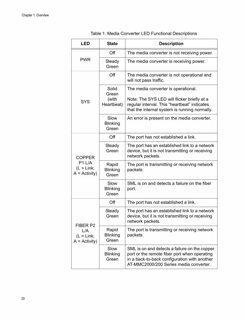
Table 1 on page 20 describes the media converter’s LEDs.
PWR
SYS
FIBERP2L/A
COPPERP1L/A
19
Chapter 1: Overview
Table 1. Media Converter LED Functional Descriptions
LED State Description
PWR
Off The media converter is not receiving power.
Steady Green
The media converter is receiving power.
SYS
Off The media converter is not operational and will not pass traffic.
Solid Green (with
Heartbeat)
The media converter is operational.
Note: The SYS LED will flicker briefly at a regular interval. This “heartbeat” indicates that the internal system is running normally.
Slow Blinking Green
An error is present on the media converter.
COPPER P1 L/A
(L = Link;A = Activity)
Off The port has not established a link.
Steady Green
The port has an established link to a network device, but it is not transmitting or receiving network packets.
Rapid Blinking Green
The port is transmitting or receiving network packets.
Slow Blinking Green
SML is on and detects a failure on the fiber port.
FIBER P2 L/A
(L = Link;A = Activity)
Off The port has not established a link.
Steady Green
The port has an established link to a network device, but it is not transmitting or receiving network packets.
Rapid Blinking Green
The port is transmitting or receiving network packets.
Slow Blinking Green
SML is on and detects a failure on the copper port or the remote fiber port when operating in a back-to-back configuration with another AT-MMC2000/200 Series media converter.
20

AT-MMC2000/200 Series Mini Switching Media Converter Installation Guide
SmartMissingLink™
(SML)
If one of the Ethernet connections to the media converter loses link, the Smart MissingLink™ (SML) feature allows you to determine which port still has a valid connection and which port requires troubleshooting. The value to this type of network monitoring and fault notification is that you can quickly determine which media converter port has failed and troubleshoot the specific area where the problem is occurring.
When the media converter detects a loss of connection on one of the ports, the port’s L/A LED is turned off. At the same time, the media converter causes the opposite port’s L/A LED to blink while simultaneously turning OFF that port’s Ethernet connection to its end node. This occurs even though the properly operating port had a valid connection before the failure occurred: The reason for this is so that its end node is notified that the data path has been compromised, and immediate action is required.
For example, if the network connection to the media converter’s twisted-pair port fails (as shown in Figure 5 on page 22), the FIBER P2 L/A LED blinks slowly while the fiber port’s link is turned OFF. The COPPER P2 L/A LED is turned OFF, indicating a failed connection on the twisted-pair port.
If the failure had started with the fiber-optic cabling (as shown in Figure 4), then the COPPER P2 L/A LED would blink slowly, and the FIBER P2 L/A LED would turn OFF.
SML Example Scenarios
Following are example scenarios with one SML enabled media converter connected between two end nodes.
Figure 3 shows media converter and end node L/A LED behavior with SML enabled under normal conditions.
Figure 3. SML in Normal Condition
Figure 4 shows media converter and end node L/A LED behavior with SML enabled with a fiber connection down.
Figure 4. SML with Fiber Connection Down
AT-MMC2000/200
Copper L/A Fiber L/A
End Node Copper Cable Fiber Cable
Link LED On
End Node
Link LED OnLED On LED On
AT-MMC2000/200
Copper L/A Fiber L/A
End Node Copper Cable Fiber Cable
Link LED Off
End Node
Link LED OffLED Blinking LED Off
21
Chapter 1: Overview
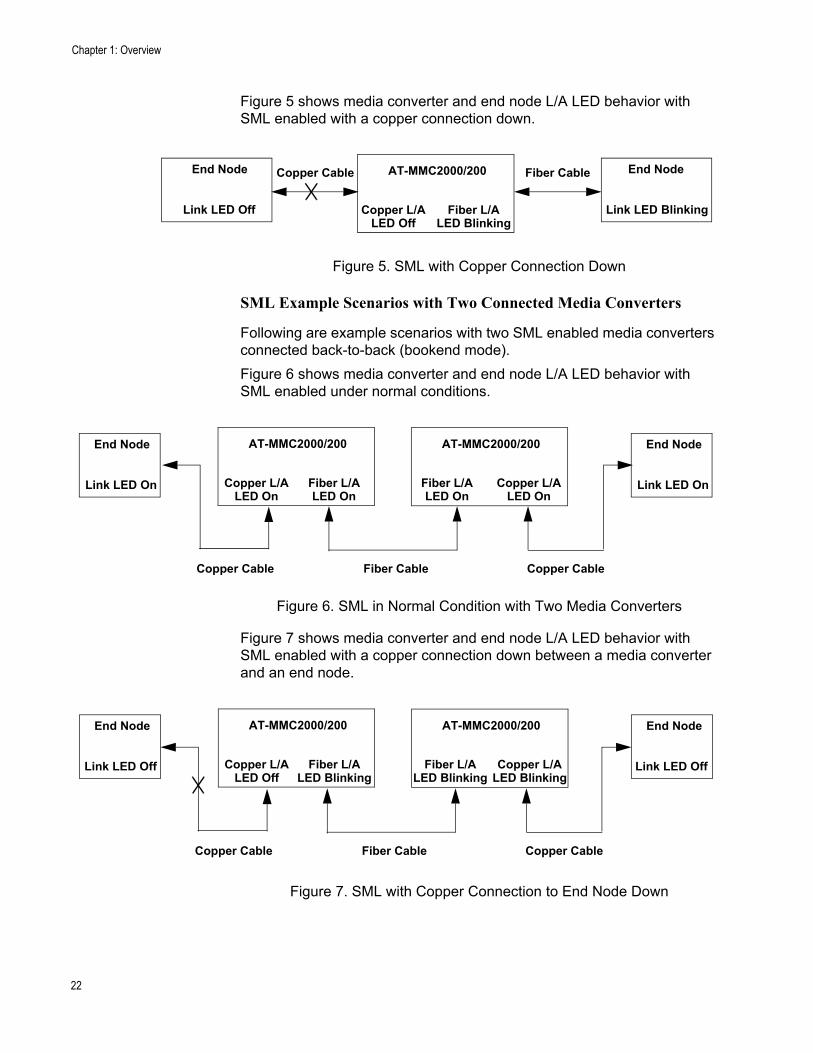
Figure 5 shows media converter and end node L/A LED behavior with SML enabled with a copper connection down.
Figure 5. SML with Copper Connection Down
SML Example Scenarios with Two Connected Media Converters
Following are example scenarios with two SML enabled media converters connected back-to-back (bookend mode).
Figure 6 shows media converter and end node L/A LED behavior with SML enabled under normal conditions.
Figure 6. SML in Normal Condition with Two Media Converters
Figure 7 shows media converter and end node L/A LED behavior with SML enabled with a copper connection down between a media converter and an end node.
Figure 7. SML with Copper Connection to End Node Down
AT-MMC2000/200
Copper L/A Fiber L/A
End Node Copper Cable Fiber Cable
Link LED Off
End Node
Link LED BlinkingLED Off LED Blinking
AT-MMC2000/200
Fiber Cable
End Node
Link LED On
End Node
Link LED On
AT-MMC2000/200
Copper L/A Fiber L/ALED On LED On
Fiber L/ALED On
Copper L/ALED On
Copper Cable Copper Cable
AT-MMC2000/200End Node
Link LED Off
End Node
Link LED Off
AT-MMC2000/200
Copper L/A Fiber L/ALED Off LED Blinking
Fiber L/ALED Blinking
Copper L/ALED Blinking
Fiber CableCopper Cable Copper Cable
22

AT-MMC2000/200 Series Mini Switching Media Converter Installation Guide
Figure 8 shows media converter and end node L/A LED behavior with SML enabled with a fiber connection down between two media converters.
Figure 8. SML with Fiber Connection Between Media Converters Down
Enabling SML
To enable SML on the unit, set the SML ON/OFF DIP switch on the rear panel of the unit to the ON (up) position. See Figure 9.
Figure 9. AT-MMC2000/200 Series Converter Rear Panel DIP Switches
External AC/DCPower Adapter
An external AC/DC power adapter is included with the media converter for standalone operation. The power adapter supplies 12 VDC to the media converter. Allied Telesis supplies a UL approved safety compliant AC power adapter for the 120 and 240 VAC versions with a regulated output of 12 VDC. The power required for the media converter is 12 VDC, 200 mA.
NoteThe media converter power receptacle has a twist-and-lock barrel which is locked by turning the power cord clockwise one-quarter turn.
AT-MMC2000/200End Node
Link LED Off
End Node
Link LED Off
AT-MMC2000/200
Copper L/A Fiber L/ALED Blinking LED Off
Fiber L/ALED Off
Copper L/ALED Blinking
Fiber CableCopper Cable Copper Cable
PORT 1
SML ON/OFF
(In Auto Negotiation position)
23

Chapter 1: Overview
Front and Back Panels
Figure 10 illustrates the front panel of the AT-MMC2000/SC and AT-MMC200/SC Media Converters.
Figure 10. AT-MMC2000/SC and AT-MMC200/SC Front Panel
Figure 11 illustrates the front panel of the AT-MMC2000/ST and AT-MMC200/ST Media Converters.
Figure 11. AT-MMC2000/ST and AT-MMC200/ST Front Panel
Base-TTwisted-Pair Port
Fiber SC TX & RXPorts
Base-TTwisted-Pair Port
L/A LEDFiber PortL/A LED
Fiber ST TX & RXPorts Fiber Port
L/A LED
Base-TTwisted-Pair Port
Base-TTwisted-Pair Port
L/A LED
24
AT-MMC2000/200 Series Mini Switching Media Converter Installation Guide
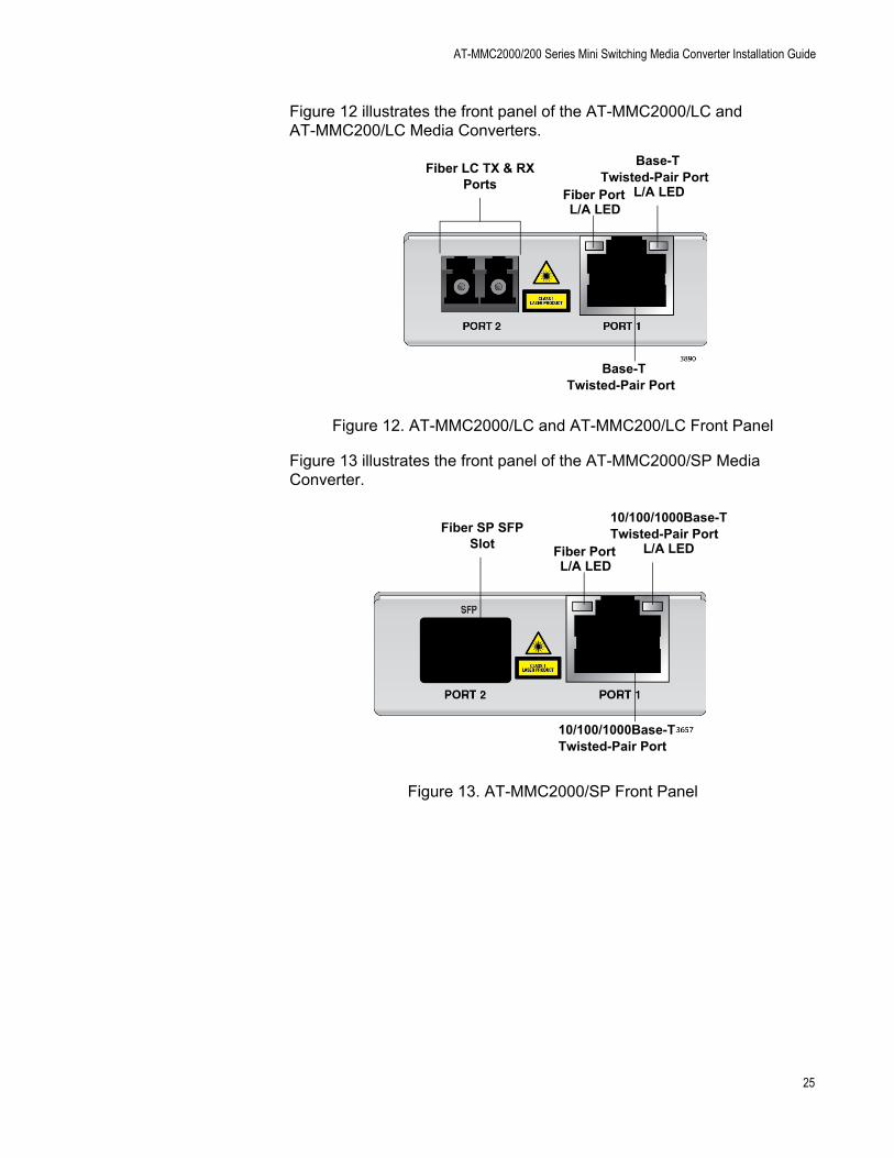
Figure 12 illustrates the front panel of the AT-MMC2000/LC and AT-MMC200/LC Media Converters.
Figure 12. AT-MMC2000/LC and AT-MMC200/LC Front Panel
Figure 13 illustrates the front panel of the AT-MMC2000/SP Media Converter.
Figure 13. AT-MMC2000/SP Front Panel
Base-TTwisted-Pair Port
Fiber LC TX & RXPorts
Base-TTwisted-Pair Port
L/A LEDFiber PortL/A LED
Fiber SP SFPSlot
10/100/1000Base-TTwisted-Pair Port
10/100/1000Base-TTwisted-Pair Port
L/A LEDFiber PortL/A LED
25

Chapter 1: Overview
Figure 14 illustrates the media converter back panel.
Figure 14. Media Converter Back Panel
12 VDC Input
SYS LED
PWR LEDSML ON/OFFDIP Switch
100Mbps Full Duplex/Auto Negotiation
DIP Switch
26

AT-MMC2000/200 Series Mini Switching Media Converter Installation Guide
Twisted-Pair Port
The twisted-pair port features an eight-pin RJ45 connector that uses four pins at 10 or 100 Mbps and all eight pins at 1000 Mbps. For the port pinouts, see “RJ45 Connector and Port Pinouts” on page 56.
The port has a maximum operating distance of 100 meters (328 feet). For twisted-pair port cabling specifications, refer to Table 2 on page 33.
You can set the twisted-pair port to 100 Mbps full-duplex mode or Auto-Negotiation mode using the PORT 1 (right) DIP switch of the two DIP switches on the rear panel. See Figure 9 on page 23.
When this DIP switch is in the FORCE 100 F/D (up) position, the twisted-pair port is forced to 100 Mbps full-duplex mode, and Auto Negotiation is disabled.
When in the AUTO NEG (down) position, the twisted-pair port operates in Auto-Negotiation mode.
Note100 Mbps full-duplex mode should not be used unless absolutely necessary because forcing 100 Mbps full-duplex in most applications is likely to cause a duplex mismatch, in turn, causing poor network performance. 100 Mbps full-duplex mode should only be used when the link partner is already forced to 100 Mbps full-duplex operation, and Auto Negotiation is disabled on the link partner. In this specific case, using Auto Negotiation on the media converter would result in a duplex mismatch.
27

Chapter 1: Overview
Reset the Media Converter
Reset the media converter by powering OFF then powering ON the unit.
28

Chapter 2
Installation
This chapter contains the following sections:
“Reviewing Safety Precautions” on page 30
“Selecting a Site for the Media Converter” on page 32
“Planning the Installation” on page 33
“Unpacking the Media Converter” on page 36
“Installing the Media Converter on a Desktop” on page 41
“Installing the Media Converter on a Wall” on page 42
“Installing the SFP Transceiver” on page 45
“Powering On and Cabling the Media Converter” on page 48
29

Chapter 2: Installation
Reviewing Safety Precautions
Review the following safety precautions before you begin to install the chassis or any of its components.
NoteThe indicates that a translation of the safety statement is available in a PDF document titled Translated Safety Statements on the Allied Telesis website at www.alliedtelesis.com/support.
Caution
Air vents must not be blocked and must have free access to the room ambient air for cooling. E6
NoteAll Countries: Install product in accordance with local and National Electrical Codes. E8
NoteThe power input must be provided from SELV source only, per IEC60950. Do not connect to a centralized DC battery bank. E31
Warning
Operating Temperature. This product is designed for a maximum ambient temperature of 50° degrees C. E57
Caution
Failing to pick up the ferrule tip when you reach the bottom of the cleaning surface can result in static electricity that can damage the fiber-optic cable. E82
30
AT-MMC2000/200 Series Mini Switching Media Converter Installation Guide
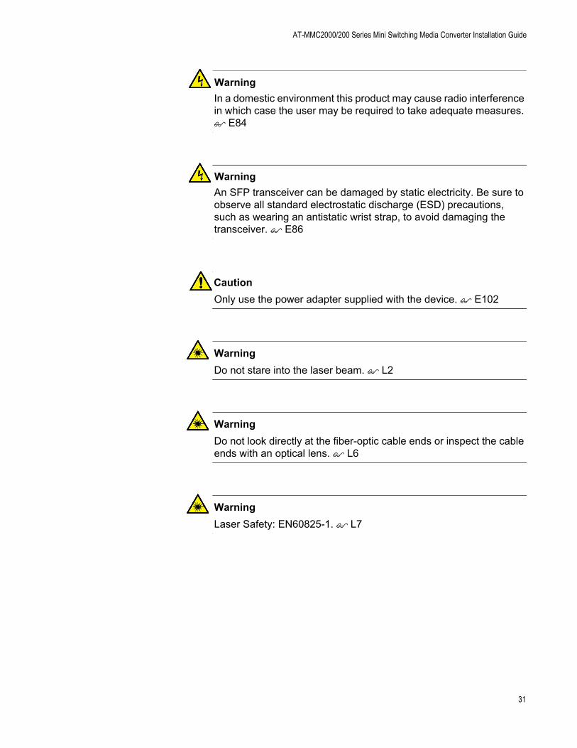
Warning
In a domestic environment this product may cause radio interference in which case the user may be required to take adequate measures. E84
Warning
An SFP transceiver can be damaged by static electricity. Be sure to observe all standard electrostatic discharge (ESD) precautions, such as wearing an antistatic wrist strap, to avoid damaging the transceiver. E86
Caution
Only use the power adapter supplied with the device. E102
Warning
Do not stare into the laser beam. L2
Warning
Do not look directly at the fiber-optic cable ends or inspect the cable ends with an optical lens. L6
Warning
Laser Safety: EN60825-1. L7
31

Chapter 2: Installation
Selecting a Site for the Media Converter
Observe the following requirements when choosing a site for your media converter:
If you are installing the media converter on a table, verify that the table is level and secure.
The power outlet for the media converter should be located near the unit and should be easily accessible.
The site should provide for easy access to the ports on the front of the media converter. This will make it easier for you to connect and disconnect cables, as well as view the media converter’s LEDs.
Air flow around the unit and through its vents on the side should not be restricted so that the media converter can maintain adequate cooling.
Do not place objects on top of the media converter.
Do not expose the media converter to moisture or water.
You should use dedicated power circuits or power conditioners to supply reliable electrical power to the network devices.
32
AT-MMC2000/200 Series Mini Switching Media Converter Installation Guide
Planning the Installation
Be sure to observe the following guidelines when planning the installation of your media converter.
On the AT-MMC2000 media converters, the end node connected to the fiber connector on the media converter must operate at 1000 Mbps, except for the AT-MMC2000/SP when using a 100 Mbps SFP module.
On the AT-MMC200 media converters, the end node connected to the fiber connector on the media converter must operate at 100 Mbps.
The two end-nodes connected to the ports of the media converter must operate with the same duplex mode, either half- or full-duplex. The twisted-pair port on the media converter can operate in either mode with Auto Negotiation enabled.
The devices connected to the two ports on the media converter can be a network adapter card, repeater, switch, media converter, or router.
The twisted-pair port has a maximum operating distance of 100 meters (328 feet).
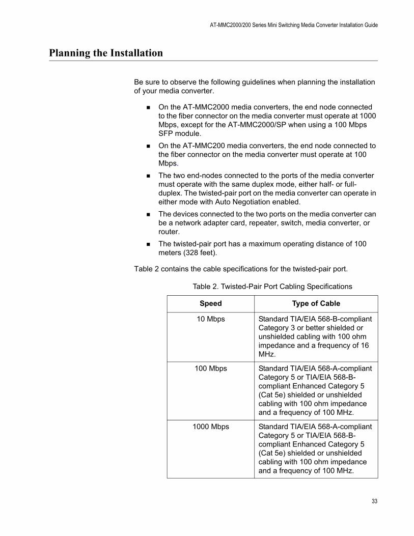
Table 2 contains the cable specifications for the twisted-pair port.
Table 2. Twisted-Pair Port Cabling Specifications
Speed Type of Cable
10 Mbps Standard TIA/EIA 568-B-compliant Category 3 or better shielded or unshielded cabling with 100 ohm impedance and a frequency of 16 MHz.
100 Mbps Standard TIA/EIA 568-A-compliant Category 5 or TIA/EIA 568-B-compliant Enhanced Category 5 (Cat 5e) shielded or unshielded cabling with 100 ohm impedance and a frequency of 100 MHz.
1000 Mbps Standard TIA/EIA 568-A-compliant Category 5 or TIA/EIA 568-B-compliant Enhanced Category 5 (Cat 5e) shielded or unshielded cabling with 100 ohm impedance and a frequency of 100 MHz.
33

Chapter 2: Installation
For speed/duplex interactions between the copper port on the AT-MMC2000 and the copper link partner, refer to Table 3 for allowable speed/duplex combinations.
For speed/duplex interactions between the copper port on the AT-MMC200 and the copper link partner, refer to Table 4 on page 35 for allowable speed/duplex combinations.
Table 3. Copper Connection Speed/Duplex Settings and Resulting Speed - AT-MMC2000
AT-MMC2000 Copper Port
Speed/Duplex Setting
Copper Link Partner Port Setting
Auto Negotiation 100Mbps Force Full Duplex
100Mbps Force Half Duplex
1000Mbps Force Full Duplex*
Auto Negotiation 1000Mbps full duplex connection for Gigabit Link Partners
100Mbps full duplex connection for 100Mbps Link Partners
Duplex mismatch – not supported
100Mbps half duplex connection
1000Mbps full duplex connection
100Mbps Full Duplex
Duplex mismatch – not supported
100Mbps full duplex connection
Duplex mismatch – not supported
No connection
*Although 1000Mbps connections require Auto Negotiation, some switches allow the option of only advertising 1000Mbps speed.
Note: The fiber port always runs at 1000Mbps full duplex.
34

AT-MMC2000/200 Series Mini Switching Media Converter Installation Guide
NoteThe twisted-pair port on the media converter features Auto MDI/MDI-X when operating at 10, 100, or 1000 Mbps. The port is configured as MDI or MDI-X when it is connected to an end node. Consequently, you can use a straight-through twisted-pair cable when connecting any type of network device to the twisted-pair port on the media converter.
For the fiber-optic port specifications, refer to “Fiber-Optic Port Specifications” on page 58.
Table 4. Copper Connection Speed/Duplex Settings and Resulting Speed - AT-MMC200
AT-MMC200 Copper Port
Speed/Duplex Setting
Copper Link Partner Port Setting
Auto Negotiation 100Mbps Force Full Duplex
100Mbps Force Half Duplex
1000Mbps Force Full Duplex*
Auto Negotiation 100Mbps full duplex connection
Duplex mismatch – not supported
100Mbps half duplex connection
No connection
100Mbps Full Duplex
Duplex mismatch – not supported
100Mbps full duplex connection
Duplex mismatch – not supported
No connection
*Although 1000Mbps connections require Auto Negotiation, some switches allow the option of only advertising 1000Mbps speed.
Note: The fiber port always runs at 100Mbps full duplex.
35

Chapter 2: Installation
Unpacking the Media Converter
To unpack the media converter, perform the following procedure:
1. Remove all of the components from the shipping package.
NoteStore the packaging material in a safe location. You must use the original shipping material if you need to return the unit to Allied Telesis.
2. Place the media converter on a level, secure surface.
3. In addition to the media converter, verify that the shipping container includes the following items as follows:
Figure 15 on page 37 shows shipping container items for the AT-MMC2000/SC and AT-MMC200/SC.
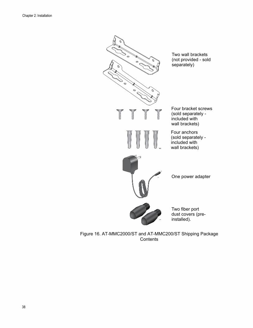
Figure 16 on page 38 shows shipping container items for the AT-MMC2000/ST and AT-MMC200/ST.
Figure 17 on page 39 shows shipping container items for the AT-MMC2000/LC and AT-MMC200/LC.
Figure 18 on page 40 shows shipping container items for the AT-MMC2000/SP.
36

AT-MMC2000/200 Series Mini Switching Media Converter Installation Guide
Figure 15. AT-MMC2000/SC and AT-MMC200/SC Shipping Package Contents
Two wall brackets
Four bracket screws
One power adapter
One fiber portdust cover (pre-installed).
(not provided - soldseparately)
(sold separately -included withwall brackets)
Four anchors(sold separately -included withwall brackets)
37
Chapter 2: Installation
Figure 16. AT-MMC2000/ST and AT-MMC200/ST Shipping Package Contents
One power adapter
Two fiber portdust covers (pre-installed).
Two wall brackets(not provided - soldseparately)
Four bracket screws(sold separately -included withwall brackets)
Four anchors(sold separately -included withwall brackets)
38

AT-MMC2000/200 Series Mini Switching Media Converter Installation Guide
Figure 17. AT-MMC2000/LC and AT-MMC200/LC Shipping Package Contents
One power adapter
One fiber portdust cover (pre-installed).
Two wall brackets(not provided - soldseparately)
Four bracket screws(sold separately -included withwall brackets)
Four anchors(sold separately -included withwall brackets)
39

Chapter 2: Installation
Figure 18. AT-MMC2000/SP Shipping Package Contents
One power adapter
One SFP slot dust cover (pre-installed).
Two wall brackets(not provided - soldseparately)
Four bracket screws(sold separately -included withwall brackets)
Four anchors(sold separately -included withwall brackets)
40
AT-MMC2000/200 Series Mini Switching Media Converter Installation Guide
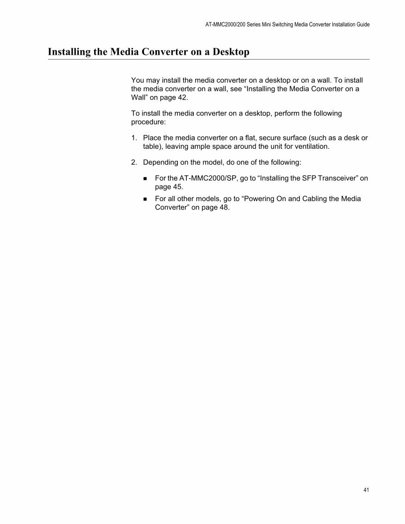
Installing the Media Converter on a Desktop
You may install the media converter on a desktop or on a wall. To install the media converter on a wall, see “Installing the Media Converter on a Wall” on page 42.
To install the media converter on a desktop, perform the following procedure:
1. Place the media converter on a flat, secure surface (such as a desk or table), leaving ample space around the unit for ventilation.
2. Depending on the model, do one of the following:
For the AT-MMC2000/SP, go to “Installing the SFP Transceiver” on page 45.
For all other models, go to “Powering On and Cabling the Media Converter” on page 48.
41
Chapter 2: Installation
Installing the Media Converter on a Wall
To install the media converter on a wall, perform the following procedure:
1. Place the media converter on a table.
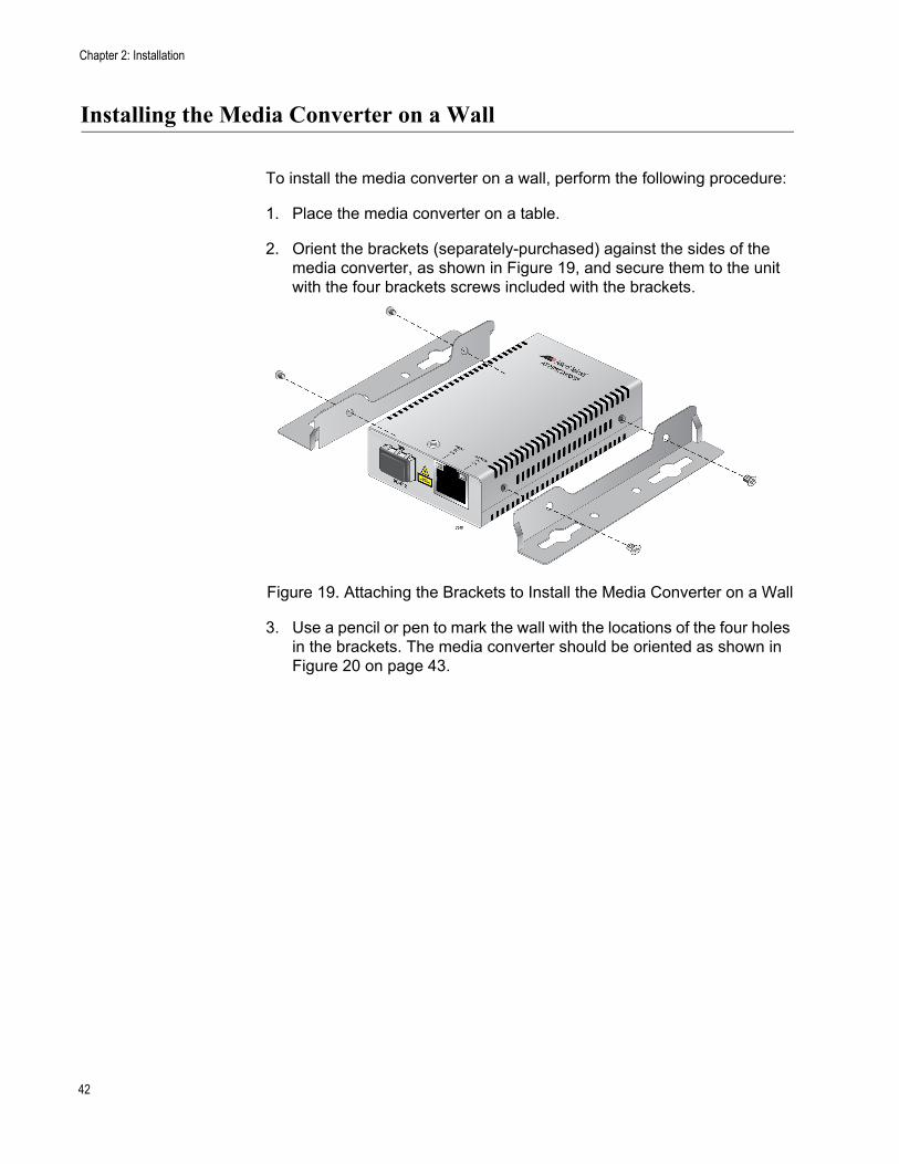
2. Orient the brackets (separately-purchased) against the sides of the media converter, as shown in Figure 19, and secure them to the unit with the four brackets screws included with the brackets.
Figure 19. Attaching the Brackets to Install the Media Converter on a Wall
3. Use a pencil or pen to mark the wall with the locations of the four holes in the brackets. The media converter should be oriented as shown in Figure 20 on page 43.
42

AT-MMC2000/200 Series Mini Switching Media Converter Installation Guide
Figure 20. Marking the Screw Hole Locations
4. Install four plastic anchors (included with separately purchased brackets) into the wall, at the locations marked in the previous step.
5. Secure the media converter to the wall using four wall mounting screws (not provided). See Figure 21 on page 44.
Mark locations Mark locations
43

Chapter 2: Installation
Figure 21. Securing the Media Converter to the Wall
6. Depending on the model, do one of the following:
For the AT-MMC2000/SP, go to “Installing the SFP Transceiver” on page 45.
For all other models, go to “Powering On and Cabling the Media Converter” on page 48.
44

AT-MMC2000/200 Series Mini Switching Media Converter Installation Guide
Installing the SFP Transceiver
To install an SFP transceiver, perform the following procedure:
NoteThe transceiver can be hot-swapped; you do not need to power off the media converter to install a transceiver. However, always remove the cable before removing the transceiver.
NoteYou should always install the transceiver before connecting the fiber-optic cable to it.
1. Remove the transceiver from its shipping container and store the packaging material in a safe location.
Warning
An SFP transceiver can be damaged by static electricity. Be sure to observe all standard electrostatic discharge (ESD) precautions, such as wearing an antistatic wrist strap, to avoid damaging the transceiver. E86
2. Remove the dust plug from the SFP slot. See Figure 22.
Figure 22. Removing the Dust Plug from an SFP Slot
3. Position the SFP transceiver with the label facing up.
45

Chapter 2: Installation
4. Slide the transceiver into the SFP slot until it clicks into place. See Figure 23.
Figure 23. Inserting the SFP
5. Verify that the handle on the transceiver is in the upright position, as shown in Figure 24. This secures the transceiver and prevents it from being dislodged from the slot.
Figure 24. Positioning the SFP Handle in the Upright Position
NoteSFP transceivers are dust-sensitive. Always keep the plug in the optical bores when a fiber-optic cable is not installed, or when storing the SFP. When you do remove the plug, keep it for future use.
NoteUnnecessary removal and insertion of an SFP can lead to premature failure.
SFP TransceiverHandle
46

AT-MMC2000/200 Series Mini Switching Media Converter Installation Guide
For information on the cable specifications of the SFP, consult the documentation shipped with the SFP.
6. Go to “Powering On and Cabling the Media Converter” on page 48.
47

Chapter 2: Installation
Powering On and Cabling the Media Converter
CablingGuidelines
Observe the following guidelines when connecting twisted-pair and fiber-optic cables to the ports on the media converter:
The connector on the cable should fit snugly into the port on the media converter. The tab on the connector should lock the connector into place.
Because the twisted-pair port has Auto MDI/MDI-X, you may use straight-through twisted-pair cable to connect any type of network device to that port.
For the fiber optic cables, refer to the cable manufacturer specification for the minimum bend radius.
Applying Powerand Connecting
the NetworkCables
To apply power to the media converter and connect the network cables, perform the following steps:
1. Plug the DC of the external power adapter to the power receptacle connector labeled 12VDC on the back panel of the media converter and turn the cord clockwise one-quarter turn to lock, as shown in Figure 25.
Figure 25. Connecting 12VDC Powered Unit
48
AT-MMC2000/200 Series Mini Switching Media Converter Installation Guide
2. Plug the power adapter to a power outlet. Refer to “Power Specifications” on page 56 for power requirements.
3. Verify that the PWR LED is lit green. If the PWR LED is off, refer to “Troubleshooting” on page 51.
4. Verify that the SYS LED is lit green. If the SYS LED is off, refer to “Troubleshooting” on page 51.
5. Remove the dust cover from the fiber-optic connector and connect the cable to the fiber-optic port.
On media converters other than the AT-MMC2000/SP: Verify that the media converter’s transmitter port (TX) is connected to the end node’s receiver port (RX) and that the media converter’s receiver port (RX) is connected to the end node’s transmitter port (TX).
For example, on the AT-MMC2000/ST media converter, connect the red TX connector on the fiber-optic cable to the transmitter port on the AT-MMC2000/ST media converter and connect the other connector to the receiver port on the end node. Then connect the black RX connector on the fiber-optic cable to the receiver port on the AT-MMC2000/ST media converter and connect the other connector to the transmitter port on the end node.
6. Connect the twisted-pair cable to the twisted-pair port. For speed/duplex interactions between the copper port and the copper link partner, refer to Table 3 on page 34 for allowable speed/duplex combinations.
7. Power on the end nodes.
The media converter is now ready for use.
49

Chapter 2: Installation
50
Chapter 3
Troubleshooting
This chapter contains information on how to troubleshoot the media converter if a problem occurs.
NoteFor further assistance, please contact Allied Telesis Technical Support at www.alliedtelesis.com/support.
Problem 1: The POWER LED on the media converter is off.
Solutions: The unit is not receiving power. Try the following:
Verify that the power cord is securely connected to the power source and to the DC connector on the back panel of the media converter.
Verify that the power outlet has power by connecting another device to it.
Try using another power adapter of the same type that came with your media converter.
Verify that the voltage from the power source is within the required levels for your region.
Problem 2: The SYS LED on the media converter is off.
Solution: An internal component on the unit is damaged or not working properly. Try power cycling the unit. If power cycling does not clear the fault, return the unit to Allied Telesis.
Problem 3: The SYS LED on the media converter is blinking slowly.
Solutions: An error is present on the unit. Try power cycling the unit.
If an AT-MMC2000/SP unit, a transmit fault may be occurring on the SFP module. The media converter will try to clear this error, but if the error persists, try the following:
Remove and re-seat the SFP module.
Try a different SFP module.
Verify the SFP module is the correct type for your application.
Problem 4: The twisted-pair port on the media converter is connected to an end node, but the port’s COPPER P1 L/A LED is off.
51
Chapter 3: Troubleshooting
Solutions: The port is unable to establish a link to an end node. Try the following:
Verify that the end node connected to the twisted-pair port is powered on and is operating properly.
Verify that the twisted-pair cable is securely connected to the port on the media converter channel and to the port on the remote end-node.
Verify that the port is connected to the correct twisted-pair cable. This is to eliminate the possibility that the port is connected to the wrong end-node, such as a powered-off device.
Try connecting another end node to the twisted-pair port with a different cable. If the twisted-pair port is able to establish a link, then the problem is with the cable or the other end-node.
Verify that the twisted-pair cable does not exceed 100 meters (328 feet).
Verify that the end node connected to the media converter is operating at the same speed.
Verify that you are using the appropriate category of twisted-pair cable: Category 3 or better for 10 Mbps operation and Category 5 and Category 5E for 100 and 1000 Mbps operation.
NoteA 1000Base connection may require 5 to 10 seconds to establish a link.
Problem 5: The FIBER P2 L/A LED for the fiber-optic port is off.
Solutions: The fiber-optic port on the transceiver is unable to establish a link to an end node. Try the following:
Verify that the end node connected to the fiber-optic port is operating properly.
Verify that the fiber-optic cable is securely connected to the port on the media converter channel and to the port on the remote end-node.
Verify that the end node connected to the media converter is operating at the same speed.
On media converters other than the AT-MMC2000/SP: Verify that the media converter’s transmitter port (TX) is connected to the end node’s receiver port (RX) and that the media converter’s receiver port (RX) is connected to the end node’s transmitter port (TX).
On the AT-MMC2000/SP, check that the SFP module is fully inserted in the slot.
52

AT-MMC2000/200 Series Mini Switching Media Converter Installation Guide
On the AT-MMC2000/SP, verify that the operating specifications and wave lengths of the fiber-optic port on the SFP transceiver and the remote end-node are compatible.
Verify that the correct type of fiber-optic cabling is being used.
Verify that the wavelength between the media converter and end node matches, and the media converter fiber port is connected to a multi-mode (not single-mode) port on the end node.
Verify that the port is connected to the correct fiber-optic cable. This is to eliminate the possibility that the port is connected to the wrong remote end-node, such as a powered-off device.
Try connecting another end node to the fiber-optic port using a different cable. If the port is able to establish a link, then the problem is with the cable or with the other end node.
If the remote end-node is a management device, use its management firmware to determine whether its port is enabled.
Test the attenuation on the fiber-optic cable with a fiber-optic tester to determine whether the optical signal is too weak (sensitivity) or too strong (maximum input power).
Problem 6: Network performance between the twisted-pair port on the media converter and an end node is slow.
Solution: There might be a duplex mode mismatch between the port and the end node. This occurs when a twisted-pair port using Auto Negotiation is connected to a device with a fixed duplex mode of full duplex. If this is the cause of the problem, adjust the duplex mode of the port on the end node or on the media converter so that both ports are using the same duplex mode.
53

Chapter 3: Troubleshooting
54

Appendix A
Technical Specifications
Below are the technical specifications for the media converters. The specification categories are as follows:
“Physical Specifications”
“Environmental Specifications”
“Power Specifications” on page 56
“Safety and Electromagnetic Emissions Certifications” on page 56
“RJ45 Connector and Port Pinouts” on page 56
“Fiber-Optic Port Specifications” on page 58
Physical Specifications
Environmental Specifications
Table 5. Physical Specifications
DimensionsW x D x H
50.8 mm x 99.1 mm x 20.3 mm (2.0 in x 3.9 in x 0.8 in)
Weight 0.2 kg (0.4 lb)
Table 6. Environmental Specifications
Operating Temperature 0° C to 50° C (32° F to 122° F)
Storage Temperature -15° C to 65° C (-5° F to 149° F)
Operating Humidity 5% to 90% non-condensing
Storage Humidity 5% to 95% non-condensing
Operating Altitude Range Up to 3,000 m (9,843 ft)
55

Appendix A: Technical Specifications
Power Specifications
The following specifications apply to the DC power connector on the media converter.
Safety and Electromagnetic Emissions Certifications
RJ45 Connector and Port Pinouts
Figure 26 illustrates the pin layout for the RJ45 connector and port.
Figure 26. RJ45 Connector and Port Pin Layout
Table 7. Power Specifications
Input supply voltage 12 VDC
Input current 1.0 A
Table 8. Safety and Electromagnetic Emissions Certifications
SafetyUL60950-1, EN60950-1, EN60825-1
Emissions (EMI)FCC Class A, CISPR 22 Class A, EN55022 Class A, RCM,VCCI Class A
ImmunityEN55024, EN61000-3-2, EN61000-3-3
Environmental ComplianceEU-RoHS compliant, WEEEChina RoHS compliant
56

AT-MMC2000/200 Series Mini Switching Media Converter Installation Guide
Table 9 lists the pin signals when a port is operating in the MDI configuration at 10 or 100 Mbps.
Table 10 lists the pin signals when a port is operating in the MDI-X configuration at 10 or 100 Mbps.
Table 11 lists the pin signals when a port is operating at 1000 Mbps.
Table 9. MDI Pin Signals (10 or 100 Mbps)
Pin Signal
1 TX+
2 TX-
3 RX+
6 RX-
Table 10. MDI-X Pin Signals (10 or 100 Mbps)
Pin Signal
1 RX+
2 RX-
3 TX+
6 TX-
Table 11. Pin Signals (1000 Mbps)
Pin Pair Signal
1 1 TX and RX+
2 1 TX and RX-
3 2 TX and RX+
4 3 TX and RX+
5 3 TX and RX-
6 2 TX and RX-
7 4 TX and RX+
8 4 TX and RX-
57

Appendix A: Technical Specifications
Fiber-Optic Port Specifications
The fiber type for the media converter is multimode.
Table 12 lists fiber-optic port specifications for the AT-MMC2000 media converters.
NoteFiber optic port specifications for the AT-MMC2000/SP are dependent upon the type of SFP inserted.
Table 13 lists fiber-optic port specifications for the AT-MMC200 media converters.
Table 12. AT-MMC2000 Fiber-Optic Port Specifications
Fiber Optic
Diameter(microns)
Optical Wavelength
Launch Power
(dBm)1Receive Power (dBm) Max.
DistanceMin. Max. Min. Typical Saturation
50/125 850 nm -9.5 -4 -17 -20 -3500 m
(1,640 ft)
62.5/125 850 nm -9 -4 -17 -20 -3220 m (722 ft)
1. The launch power is measured 1 meter (3.28 feet) from the transmitter.
Table 13. AT-MMC200 Fiber-Optic Port Specifications
Fiber Optic
Diameter(microns)
Optical Wavelength
Launch Power
(dBm)1Receive Power (dBm) Max.
DistanceMin. Max. Min. Typical Saturation
50/125 1310 nm -19 -14 -32 -34 -32 km
(6,562 ft)
62.5/125 1310 nm -22.5 -14 -32 -34 -32 km
(6,562 ft)
1. The launch power is measured 1 meter (3.28 feet) from the transmitter.
58

Appendix B
Cleaning Fiber-Optic Connectors
This appendix contains the following sections:
“Introduction”
“Using a Cartridge-Type Cleaner” on page 60
“Using a Swab” on page 62
This appendix describes how to clean fiber-optic connectors.
Introduction
The fiber-optic connector consists of a fiber-optic plug and its adapter. The end of the fiber-optic cable is held in the core of the ferrule in the plug. Light signals are transmitted through the core of the fiber. Even minor smudges, or dirt, on the end face of the fiber (completely invisible to the naked eye) can disrupt light transmission and lead to failure of the component or of the entire system. Therefore, it is of utmost importance to clean all fiber-optic connectors before use.
Figure 27 shows the ferrule in an SC connector.
Figure 27. Ferrule in an SC Connector Plug
177
Ferrule
59

Appendix B: Cleaning Fiber-Optic Connectors
The end face of an unclean and clean ferrule are shown in Figure 28.
Figure 28. Unclean and Clean Ferrule
Using a Cartridge-Type Cleaner
Fiber-optic cartridge cleaners, shown in Figure 29, are available from many vendors and are typically called “cartridge cleaners”.
Figure 29. Cartridge Cleaner
NoteDo not use compressed air or aerosol air to clean a fiber-optic connector.
To clean a fiber-optic connector using a cartridge cleaner, perform the following procedure.
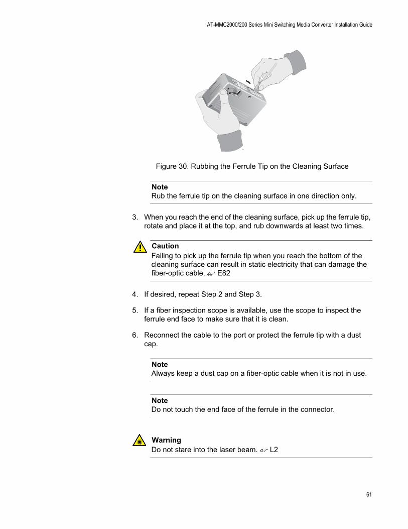
1. With one hand, hold the cartridge cleaner and push the lever on the cleaning cartridge in the direction of the arrow to expose the cleaning surface, as shown in Figure 30 on page 61.
2. Place the ferrule tip on the exposed cleaning surface and rub the ferrule in a downward direction, as shown in Figure 30 on page 61.
156Unclean Clean
TAPE A WipingDirection
PU
SH
OP
EN
PU
SH
OP
EN
100
60
AT-MMC2000/200 Series Mini Switching Media Converter Installation Guide
Figure 30. Rubbing the Ferrule Tip on the Cleaning Surface
NoteRub the ferrule tip on the cleaning surface in one direction only.
3. When you reach the end of the cleaning surface, pick up the ferrule tip, rotate and place it at the top, and rub downwards at least two times.
CautionFailing to pick up the ferrule tip when you reach the bottom of the cleaning surface can result in static electricity that can damage the fiber-optic cable. E82
4. If desired, repeat Step 2 and Step 3.
5. If a fiber inspection scope is available, use the scope to inspect the ferrule end face to make sure that it is clean.
6. Reconnect the cable to the port or protect the ferrule tip with a dust cap.
NoteAlways keep a dust cap on a fiber-optic cable when it is not in use.
NoteDo not touch the end face of the ferrule in the connector.
WarningDo not stare into the laser beam. L2
102
61
Appendix B: Cleaning Fiber-Optic Connectors
WarningDo not look directly at the fiber-optic cable ends or inspect the cable ends with an optical lens. L6
Using a Swab
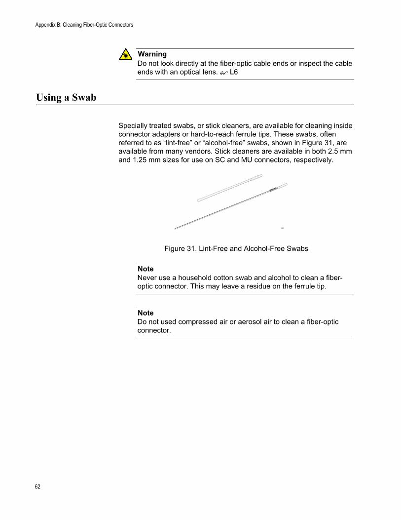
Specially treated swabs, or stick cleaners, are available for cleaning inside connector adapters or hard-to-reach ferrule tips. These swabs, often referred to as “lint-free” or “alcohol-free” swabs, shown in Figure 31, are available from many vendors. Stick cleaners are available in both 2.5 mm and 1.25 mm sizes for use on SC and MU connectors, respectively.
Figure 31. Lint-Free and Alcohol-Free Swabs
NoteNever use a household cotton swab and alcohol to clean a fiber-optic connector. This may leave a residue on the ferrule tip.
NoteDo not used compressed air or aerosol air to clean a fiber-optic connector.
106
62

AT-MMC2000/200 Series Mini Switching Media Converter Installation Guide
To clean a recessed ferrule using a swab, perform the following procedure.
1. Insert the swab into the adapter as shown in Figure 32. Rub the ferrule tip with the swab.
Figure 32. Cleaning a Recessed Ferrule
2. If desired, repeat Step 1.
3. If a fiber inspection scope is available, use the scope to inspect the connector to make sure that it is clean and to check for scratches, pits, or other problems that may affect performance.
NoteAlways keep a dust cap on a fiber-optic cable when it is not in use.
WarningDo not stare into the laser beam. L2
WarningDo not look directly at the fiber-optic cable ends or inspect the cable ends with an optical lens. L6
157
63

Appendix B: Cleaning Fiber-Optic Connectors
64