Embed Size (px)
Citation preview
613-001052 Rev. A
AT-MCF2000Multi-channel Media Converter Series
Fast and Gigabit EthernetMedia Converter Modules:
AT-MCF2012LCAT-MCF2012LC/1AT-MCF2032SP
Enclosures:AT-MCF2000AT-MCF2300
◆Installation Guide

Copyright © 2008 Allied Telesis, Inc.All rights reserved. No part of this publication may be reproduced without prior written permission from Allied Telesis, Inc.Allied Telesis and the Allied Telesis logo are trademarks of Allied Telesis, Incorporated. All other product names, company names, logos or other designations mentioned herein are trademarks or registered trademarks of their respective owners.Allied Telesis, Inc. reserves the right to make changes in specifications and other information contained in this document without prior written notice. The information provided herein is subject to change without notice. In no event shall Allied Telesis, Inc. be liable for any incidental, special, indirect, or consequential damages whatsoever, including but not limited to lost profits, arising out of or related to this manual or the information contained herein, even if Allied Telesis, Inc. has been advised of, known, or should have known, the possibility of such damages.

Electrical Safety and Emissions Standards
This product meets the following standards.
RFI Emissions FCC Class A, EN55022 Class A, EN61000-3-2, EN61000-3-3, VCCI Class A, C-TICK, CE
EMC Immunity EN55024
Electrical Safety EN60950-1 (TUV), UL 60950-1 (CULUS)
U.S. Federal Communications CommissionRadiated Energy
Note: This equipment has been tested and found to comply with the limits for a Class A digital device pursuant to Part 15 of FCC Rules. These limits are designed to provide reasonable protection against harmful interference when the equipment is operated in a commercial environment. This equipment generates, uses, and can radiate radio frequency energy and, if not installed and used in accordance with this instruction manual, may cause harmful interference to radio communications. Operation of this equipment in a residential area is likely to cause harmful interference in which case the user will be required to correct the interference at his own expense.
Note: Modifications or changes not expressly approved of by the manufacturer or the FCC, can void your right to operate this equipment.
Industry CanadaThis Class A digital apparatus complies with Canadian ICES-003.
Cet appareil numérique de la classe A est conforme à la norme NMB-003 du Canada.
Warning: In a domestic environment this product may cause radio interference in which case the user may be required to take adequate measures.
Laser Safety EN60825
3

Electrical Safety and Emissions Standards
Translated Safety StatementsImportant: The symbol indicates that a translation of the safety statement is available in the PDF document titled “Translated Safety
Statements” (613-000990) posted on the Allied Telesis website at www.alliedtelesis.com. This document is also included on the documentation CD that is shipped with the product.
4

Contents
Preface ............................................................................................................................................................ 13How this Guide is Organized ............................................................................................................................ 14Where to Find Web-based Guides ................................................................................................................... 16Contacting Allied Telesis .................................................................................................................................. 17
Online Support ........................................................................................................................................... 17Email and Telephone Support.................................................................................................................... 17Returning Products .................................................................................................................................... 17Sales and Corporate Information ............................................................................................................... 17Warranty..................................................................................................................................................... 17Management Software Updates................................................................................................................. 17
Section I: Features ..................................................................................................... 19Chapter 1: AT-MCF2000 Multi-channel Media Converter Series ............................................................... 21Hardware Components..................................................................................................................................... 22Management Software Components ................................................................................................................ 25
Chapter 2: AT-MCF2000 and AT-MCF2300 Chassis ................................................................................... 27
Chapter 3: AT-MCF2012LC, AT-MCF2012LC/1 and AT-MCF2032SP Modules ......................................... 31Overview........................................................................................................................................................... 32Front Panels ..................................................................................................................................................... 33Media Converter Channels............................................................................................................................... 34Twisted Pair Ports ............................................................................................................................................ 35Fiber Optic Ports............................................................................................................................................... 36Channel Operating Modes................................................................................................................................ 37
Link Test Mode........................................................................................................................................... 37MissingLink Mode ...................................................................................................................................... 37Smart MissingLink Mode............................................................................................................................ 39Guidelines to Using the Channel Operating Modes ................................................................................... 40
Port and Channel LEDs.................................................................................................................................... 41“A” Activity LED.......................................................................................................................................... 41“L” Link LEDs ............................................................................................................................................. 42CDC and FDC Duplex Mode and Collision LEDs ...................................................................................... 46LT, ML, and SML Channel Operating Mode LEDs..................................................................................... 48RDY/FLT LED ............................................................................................................................................ 49HBI and HBO Heartbeat LEDs................................................................................................................... 50Channel LEDs............................................................................................................................................ 50
Mode Button ..................................................................................................................................................... 51Guidelines to Using the Media Converter Modules .......................................................................................... 53
Chapter 4: AT-MCF2000M Management Module ........................................................................................ 55Overview........................................................................................................................................................... 56Front Panel ....................................................................................................................................................... 5810/100/1000Base-T Management Port ............................................................................................................ 59RS-232 Terminal Port....................................................................................................................................... 61
5

Contents
Stack Port .........................................................................................................................................................62Reset Button .....................................................................................................................................................63SD Slot ..............................................................................................................................................................65Chassis ID Jumper............................................................................................................................................66LEDs .................................................................................................................................................................67
General Status LEDs..................................................................................................................................67RS-232 Terminal Port LED.........................................................................................................................6810/100/1000Base-T Management Port LEDs.............................................................................................69ID LEDs ......................................................................................................................................................70Stack Port LED ...........................................................................................................................................70Secure Digital Memory Card Slot LED .......................................................................................................71
Chapter 5: AT-MCF2000S Stacking Module .................................................................................................73Overview ...........................................................................................................................................................74Topology ...........................................................................................................................................................75Maximum Number of Media Converter Modules in a Stack..............................................................................76Cabling the Stack Ports ....................................................................................................................................77Chassis ID Numbers .........................................................................................................................................79LEDs .................................................................................................................................................................81Chassis ID LEDs...............................................................................................................................................82Guidelines to Building a Stack ..........................................................................................................................83
Section II: Installation ...............................................................................................85Chapter 6: Reviewing the Safety Precautions .............................................................................................87
Chapter 7: Selecting a Location ...................................................................................................................91
Chapter 8: Unpacking the AT-MCF2000 or AT-MCF2300 Chassis .............................................................93
Chapter 9: Removing the Rubber Feet .........................................................................................................97
Chapter 10: Installing the AT-MCF2000AC or AT-MCF2300AC Power Supply Module ...........................99
Chapter 11: Installing the AT-MCF2KFAN Module ....................................................................................103
Chapter 12: Installing a Media Converter Module .....................................................................................107
Chapter 13: Installing the AT-MCF2000M Management Module ..............................................................111
Chapter 14: Installing the AT-MCF2000S Stacking Module .....................................................................115
Chapter 15: Installing the Chassis in an Equipment Rack .......................................................................119
Chapter 16: Grounding the AT-MCF2300 Chassis ....................................................................................123
Chapter 17: Installing the SFP Modules in the AT-MCF2032SP Module .................................................125
Chapter 18: Cabling the Ports on the Media Converter Module ..............................................................129
Chapter 19: Cabling the AT-MCF2000M and AT-MCF2000S Modules .....................................................131
Chapter 20: Powering on the Chassis ........................................................................................................135
Chapter 21: Verifying the Installation .........................................................................................................139AT-MCF2000AC and AT-MCF2300AC Power Supply Module .......................................................................140AT-MCF2KFAN and AT-MCF2300FAN Modules............................................................................................140AT-MCF2012LC, AT-MCF2012LC/1 and AT-MCF2032SP Media Converter Modules ..................................141AT-MCF2000M Management Module.............................................................................................................142AT-MCF2000S Stacking Module ....................................................................................................................142
6

AT-MCF2000 Media Converter Series Installation Guide
Chapter 22: Starting a Local Management Session ................................................................................. 143
Chapter 23: Troubleshooting the Modules ............................................................................................... 145AT-MCF2012LC, AT-MCF2012LC/1 and AT-MCF2032SP Media Converter Modules.................................. 146AT-MCF2000AC and AT-MCF2300AC Power Supply Modules..................................................................... 150AT-MCF2KFAN and AT-MCF2300FAN Modules ........................................................................................... 151AT-MCF2000M Management Module ............................................................................................................ 153AT-MCF2000S Stacking Module .................................................................................................................... 155
Chapter 24: Replacing the Modules ........................................................................................................... 157Replacing a Media Converter Module ............................................................................................................ 158Replacing the AT-MCF2000M or AT-MCF2000S Module .............................................................................. 161Replacing the AT-MCF2000AC or AT-MCF2300AC Power Supply ............................................................... 164Replacing the AT-MCF2300FAN Module ....................................................................................................... 168
Appendix A: Technical Specifications ...................................................................................................... 171Environmental Specifications ......................................................................................................................... 171Standards ....................................................................................................................................................... 171Safety and Electromagnetic Emissions Certifications .................................................................................... 172AT-MCF2000 Chassis .................................................................................................................................... 172AT-MCF2300 Chassis .................................................................................................................................... 172AT-MCF2000AC Power Supply Module ......................................................................................................... 173AT-MCF2300AC Power Supply Module ......................................................................................................... 173AT-MCF2012LC, AT-MCF2012LC/1 and AT-MCF2032SP Media Converter Modules.................................. 174
Specifications ........................................................................................................................................... 174Twisted Pair Port Pinouts......................................................................................................................... 174100Base-FX Fiber Optic Ports ................................................................................................................. 175
AT-MCF2000M Management Module ............................................................................................................ 176Specifications ........................................................................................................................................... 17610/100/1000Base-T Port Pin-outs............................................................................................................ 176RS-232 Terminal Port Pinouts ................................................................................................................. 177
AT-MCF2000S Stacking Module .................................................................................................................... 178AT-MCF2KFAN Module.................................................................................................................................. 178AT-MCF2300FAN Module .............................................................................................................................. 178
Appendix B: DIP Switch Settings for the AT-MCF2000S Stacking Module ............................................ 179
Appendix C: Cleaning Fiber Optic Connectors ........................................................................................ 181Using a Cartridge-Type Cleaner..................................................................................................................... 182Using a Swab ................................................................................................................................................. 184
Index ............................................................................................................................................................. 187
7

Contents
8

Figures
Figure 1: AT-MCF2000 and AT-MCF2300 Chassis..............................................................................................................27Figure 2: AT-MCF2000 Chassis Slots ..................................................................................................................................28Figure 3: AT-MCF2300 Chassis Sots ...................................................................................................................................29Figure 4: AT-MCF2000 Series Media Converter Module .....................................................................................................32Figure 5: Front Panel of the AT-MCF2012LC Module ..........................................................................................................33Figure 6: Front Panel of the AT-MCF2012LC/1 Module.......................................................................................................33Figure 7: Front Panel of the AT-MCF2032SP Module..........................................................................................................33Figure 8: Channel 1 on the Media Converter Module...........................................................................................................34Figure 9: Activity LED for a Twisted Pair Port.......................................................................................................................41Figure 10: Activity LED for a Fiber Optic Port on the AT-MCF2012LC and AT-MCF2012LC/1 Modules.............................41Figure 11: Activity LEDs for the Fiber Optic Ports on the AT-MCF2032SP Module .............................................................42Figure 12: Link LED for a Twisted Pair Port .........................................................................................................................42Figure 13: Link LED for a Fiber Optic Port on the AT-MCF2012LC and AT-MCF2012LC/1 Modules..................................43Figure 14: Link LEDs for the Fiber Optic Ports on the AT-MCF2032SP Module..................................................................43Figure 15: Duplex Mode and Collision LEDs on the AT-MCF2012LC and AT-MCF2012LC/1 Modules ..............................47Figure 16: Duplex Mode and Collision LEDs on the AT-MCF2032SP Module.....................................................................47Figure 17: Channel Operating Mode LEDs on the AT-MCF2012LC and AT-MCF2012LC/1 Modules.................................48Figure 18: Channel Operating Mode LEDs on the AT-MCF2032SP Module .......................................................................49Figure 19: RDY/FLT LED on the AT-MCF2032SP Module ..................................................................................................49Figure 20: HBI and HBO Heartbeat LEDs on the AT-MCF2032SP Module .........................................................................50Figure 21: Mode Button ........................................................................................................................................................51Figure 22: “CH” Channel LEDs on the AT-MCF2012LC and AT-MCF2012LC/1 Modules...................................................51Figure 23: Channel LEDs on the AT-MCF2032SP Module ..................................................................................................52Figure 24: AT-MCF2000M Management Module .................................................................................................................56Figure 25: Front Panel of the AT-MCF2000M Management Module....................................................................................58Figure 26: Pressing the Reset Button...................................................................................................................................64Figure 27: Chassis ID Jumper ..............................................................................................................................................66Figure 28: General Status LEDs...........................................................................................................................................67Figure 29: Link/Activity LED on the RS-232 Terminal Port...................................................................................................68Figure 30: Link/Activity and Duplex-mode LEDs on the Management Port..........................................................................69Figure 31: Chassis ID Number LEDs....................................................................................................................................70Figure 32: Link/Activity LED on the Stack Port .....................................................................................................................70Figure 33: SD Slot LED ........................................................................................................................................................71Figure 34: AT-MCF2000S Stacking Module .........................................................................................................................74Figure 35: Example Stack of Four Media Converter Chassis...............................................................................................75Figure 36: Maximum Length of a Stacking Cable.................................................................................................................75Figure 37: Cabling the AT-MCF2000M Management Module to the AT-MCF2000S Stacking Module ...............................77Figure 38: Cabling Two AT-MCF2000S Stacking Modules ..................................................................................................78Figure 39: Chassis ID Jumper on the AT-MCF2000M Management Module.......................................................................79Figure 40: Chassis ID DIP Switches on the AT-MCF2000S Stacking Module .....................................................................80Figure 41: Chassis ID Numbers............................................................................................................................................80Figure 42: Removing the Chassis Feet ................................................................................................................................97Figure 43: Removing the Blank Panel from a Power Supply Slot.........................................................................................99Figure 44: Installing the AT-MCF2000AC Power Supply Module.......................................................................................101Figure 45: Securing the AT-MCF2000AC Power Supply Module.......................................................................................101Figure 46: Installing a Retaining Clip ..................................................................................................................................102Figure 47: Removing the Cover from a Power Supply Slot ................................................................................................103Figure 48: Installing the AT-MCF2KFAN Fan Module ........................................................................................................105Figure 49: Securing the AT-MCF2KFAN Fan Module ........................................................................................................105
9

Figures
Figure 50: Removing a Blank Cover from a Media Converter Slot .....................................................................................107Figure 51: Removing the Battery Insulator .........................................................................................................................108Figure 52: Installing a Media Converter Module .................................................................................................................109Figure 53: Securing a Media Converter Module .................................................................................................................109Figure 54: Removing the Blank Panel from the Management Slot .....................................................................................111Figure 55: Setting the Chassis ID Jumper on the AT-MCF2000M Management Module...................................................113Figure 56: Removing the Battery Insulator .........................................................................................................................113Figure 57: Installing the Management Module....................................................................................................................114Figure 58: Securing the Management Module....................................................................................................................114Figure 59: Removing the Blank Panel from the Management Slot .....................................................................................115Figure 60: Setting the Chassis ID DIP Switches.................................................................................................................117Figure 61: Installing the AT-MCF2000S Stacking Module ..................................................................................................117Figure 62: Securing the AT-MCF2000S Stacking Module ..................................................................................................118Figure 63: Labelling the AT-MCF2000S Stacking Module with the Chassis ID Number ....................................................118Figure 64: Attaching a Rack-mount Bracket to the AT-MCF2000 Chassis.........................................................................119Figure 65: Attaching a Rack-mount Bracket to the AT-MCF2300 Chassis.........................................................................119Figure 66: Rack-mount Bracket Positions on the AT-MCF2300 Chassis ...........................................................................120Figure 67: Invalid Rack-mount Bracket Positions on the AT-MCF2300 Chassis................................................................121Figure 68: Stripping the Grounding Wire ............................................................................................................................123Figure 69: Attaching the Grounding Wire to the Grounding Lug.........................................................................................123Figure 70: Removing the Grounding Lug Screws...............................................................................................................124Figure 71: Attaching the Grounding Lug.............................................................................................................................124Figure 72: Removing a Dust Cover from an SFP Slot ........................................................................................................125Figure 73: Installing an SFP Module...................................................................................................................................126Figure 74: Positioning the SFP Handle...............................................................................................................................126Figure 75: Connecting an Enhanced Category 5 Network Cable to the 10/100/1000Base-T Management Port ...............131Figure 76: Cabling the AT-MCF2000M Management Module to the AT-MCF2000S Stacking Module..............................132Figure 77: Cabling Two AT-MCF2000S Stacking Modules ................................................................................................133Figure 78: Setting the ON/OFF Switch to the OFF Position ...............................................................................................135Figure 79: Raising the Retaining Clip .................................................................................................................................135Figure 80: Connecting the AC Power Cord.........................................................................................................................136Figure 81: Positioning the Power Cord Retaining Clip........................................................................................................136Figure 82: Connecting the RS-232 Serial Management Cable to the RS-232 Terminal Port .............................................143Figure 83: Command Line Prompt......................................................................................................................................144Figure 84: Covering a Broken Fan on the AT-MCF2300FAN Module ................................................................................152Figure 85: Labelling and Removing the Twisted Pair Cables and the Fiber Optic Cables .................................................158Figure 86: Installing the Dust Covers on the Fiber Optic Ports...........................................................................................158Figure 87: Removing the SFP Modules from the AT-MCF2032SP Module........................................................................159Figure 88: Removing the Media Converter Module ............................................................................................................159Figure 89: Installing the AT-MCF2KPNL1 Slot Cover over a Media Converter Slot ...........................................................160Figure 90: Disconnecting the Cables from the AT-MCF2000M and AT-MCF2000S Modules............................................161Figure 91: Removing the AT-MCF2000M Management Module or the AT-MCF2000S Stacking Module .........................162Figure 92: Installing the AT-MCF2KPNL3 Slot Cover on the Management Slot.................................................................163Figure 93: Setting the ON/OFF Switch to the OFF Position ...............................................................................................164Figure 94: Removing the Power Cord.................................................................................................................................165Figure 95: Removing the AT-MCF2000AC or AT-MCF2300AC Power Supply Module .....................................................166Figure 96: Installing the AT-MCF2KPNL2 Slot Cover over the Power Supply Slot ............................................................167Figure 97: Removing the Fan Cover...................................................................................................................................168Figure 98: Removing the AT-MCF2300FAN Module ..........................................................................................................169Figure 99: Installing a New AT-MCF2300FAN Module.......................................................................................................170Figure 100: RJ-45 Connector and Port Pin Assignments ...................................................................................................176Figure 101: RS-232 Terminal Port Pinouts .........................................................................................................................177Figure 102: Chassis ID DIP Switches on the AT-MCF2000S Stacking Module .................................................................179Figure 103: Ferrule in an SC Connector Plug.....................................................................................................................181Figure 104: Unclean and Clean Ferrule..............................................................................................................................181Figure 105: Cartridge Cleaner ............................................................................................................................................182Figure 106: Rubbing the Ferrule Tip on the Cleaning Surface ...........................................................................................183Figure 107: Lint-Free and Alcohol-Free Swabs ..................................................................................................................184Figure 108: Cleaning a Recessed Ferrule ..........................................................................................................................184
10

Tables
11
Table 1: Hardware Components ..........................................................................................................................................22Table 2: Management Software ..........................................................................................................................................25Table 3: AT-MCF2000 Chassis Slots ..................................................................................................................................28Table 4: AT-MCF2300 Chassis Slots ..................................................................................................................................29Table 5: Twisted Pair Cabling and Distances ......................................................................................................................35Table 6: Fiber Optic Ports ....................................................................................................................................................36Table 7: “A” Activity LED ......................................................................................................................................................42Table 8: Link LEDs in the Link Test Mode ...........................................................................................................................44Table 9: “L” Link LEDs in the MissingLink Mode .................................................................................................................45Table 10: “L” Link LEDs in the Smart MissingLink Mode .....................................................................................................45Table 11: CDC and FDC Duplex Mode and Collisions LEDs ..............................................................................................48Table 12: RDY/FLT LED ......................................................................................................................................................49Table 13: Cable Requirements for the 10/100/1000Base-T Management Port ...................................................................59Table 14: General Status LEDs ...........................................................................................................................................67Table 15: Link/Activity LED on the RS-232 Terminal Port ...................................................................................................68Table 16: Link/Activity LED on the Management Port .........................................................................................................69Table 17: Duplex-mode/Collisions LED on the Management Port ......................................................................................69Table 18: Link/Activity LED on the Management Port .........................................................................................................71Table 19: SD Slot LED ........................................................................................................................................................71Table 20: Cable Requirements for the Stack Ports .............................................................................................................77Table 21: LEDs on the AT-MCF2000S Stacking Module ....................................................................................................81Table 22: AT-MCF2000 Chassis Items ................................................................................................................................93Table 23: AT-MCF2300 Chassis Items ................................................................................................................................94Table 24: AT-MCF2000AC or AT-MCF2300AC Power Supply Module Items ...................................................................100Table 25: AT-MCF2KFAN Module Items ...........................................................................................................................104Table 26: AT-MCF2000 Media Converter Module Items ...................................................................................................108Table 27: AT-MCF2000M Management Module ...............................................................................................................112Table 28: AT-MCF2000S Module Items ............................................................................................................................116Table 29: 10/100Base-TX Port Pinouts .............................................................................................................................174Table 30: Fiber Optic Port Specifications for the AT-MFC2012LC Module .......................................................................175Table 31: Fiber Optic Port Specifications for the AT-MFC2012LC/1 Module ....................................................................175Table 32: 10/100/1000Base-T Management Port Pinouts at 10 or 100 Mbps ...................................................................176Table 33: 10/100/1000Base-T Management Port Pinouts at 1000 Mbps ..........................................................................176Table 34: RS-232 Terminal Port ........................................................................................................................................177Table 35: SW2 DIP Switch Settings (ID Numbers 1 to 15) for the AT-MCF2000S Stacking Module ................................179Table 36: SW2 DIP Switch Settings (ID Numbers 16 to 30) for the AT-MCF2000S Stacking Module ..............................180

Tables
12

Preface
This is the installation guide for the AT-MCF2000 Series of multi-channel, Fast and Gigabit Ethernet media converter products. In this guide you’ll learn about the features of the product and how to install the components.
This preface contains the following sections:
“How this Guide is Organized” on page 14“Where to Find Web-based Guides” on page 16“Contacting Allied Telesis” on page 17
13

Preface
How this Guide is Organized
The chapters in this guide are divided into two sections. The chapters in the first section describe the features and components of the product. If you are installing your first system, you will find the installation easier to do and will be less likely to assemble or cable the product incorrectly if you first familiarize yourself with the basics of the product by reviewing the material in these chapters.
The chapters in the second section contain the installation instructions. If you are installing a new system, Allied Telesis recommends that you perform the chapters as they are presented in the section, skipping any chapters that are not relevant to your installation. To upgrade or expand an existing system, go straight to the appropriate chapters.
Here are the sections, chapters, and appendices in this guide:
Section I, Features
Chapter 1, “AT-MCF2000 Multi-channel Media Converter Series” on page 21
Chapter 2, “AT-MCF2000 and AT-MCF2300 Chassis” on page 27
Chapter 3, “AT-MCF2012LC, AT-MCF2012LC/1 and AT-MCF2032SP Modules” on page 31
Chapter 4, “AT-MCF2000M Management Module” on page 55
Chapter 5, “AT-MCF2000S Stacking Module” on page 73
Section II, Installation
Chapter 6, “Reviewing the Safety Precautions” on page 87
Chapter 7, “Selecting a Location” on page 91
Chapter 8, “Unpacking the AT-MCF2000 or AT-MCF2300 Chassis” on page 93
Chapter 9, “Removing the Rubber Feet” on page 97
Chapter 10, “Installing the AT-MCF2000AC or AT-MCF2300AC Power Supply Module” on page 99
Chapter 11, “Installing the AT-MCF2KFAN Module” on page 103
Chapter 12, “Installing a Media Converter Module” on page 107
Chapter 13, “Installing the AT-MCF2000M Management Module” on page 111
14

AT-MCF2000 Media Converter Series Installation Guide
Chapter 14, “Installing the AT-MCF2000S Stacking Module” on page 115
Chapter 15, “Installing the Chassis in an Equipment Rack” on page 119
Chapter 16, “Grounding the AT-MCF2300 Chassis” on page 123
Chapter 17, “Installing the SFP Modules in the AT-MCF2032SP Module” on page 125
Chapter 18, “Cabling the Ports on the Media Converter Module” on page 129
Chapter 19, “Cabling the AT-MCF2000M and AT-MCF2000S Modules” on page 131
Chapter 20, “Powering on the Chassis” on page 135
Chapter 21, “Verifying the Installation” on page 139
Chapter 22, “Starting a Local Management Session” on page 143
Chapter 23, “Troubleshooting the Modules” on page 145
Chapter 24, “Replacing the Modules” on page 157
Appendix A, “Technical Specifications” on page 171Appendix B, “DIP Switch Settings for the AT-MCF2000S Stacking Module” on page 179Appendix C, “Cleaning Fiber Optic Connectors” on page 181
15

Preface
Where to Find Web-based Guides
The installation and user guides for all of the Allied Telesis products are available for viewing in portable document format (PDF) from our web site at www.alliedtelesis.com.
16

AT-MCF2000 Media Converter Series Installation Guide
Contacting Allied Telesis
This section provides Allied Telesis contact information for technical support and for sales and corporate information.
Online Support You can request technical support online from the Allied Telesis Knowledge Base at www.alliedtelesis.com/support/kb.aspx. You can submit questions to our technical support staff from the Knowledge Base and review answers to previously asked questions.
Email andTelephone
Support
For Technical Support via email or telephone, refer to the Allied Telesis web site at www.alliedtelesis.com. Select your country from the list on the web site and then select the appropriate tab.
ReturningProducts
Products for return or repair must be assigned Return Materials Authorization (RMA) numbers. A product sent to Allied Telesis without an RMA number will be returned to the sender at the sender’s expense.
To obtain an RMA number, contact the Allied Telesis Technical Support group at www.alliedtelesis.com/support/rma.aspx.
Sales andCorporate
Information
You can contact Allied Telesis for sales or corporate information at our web site at www.alliedtelesis.com.
Warranty All the products in the AT-MCF2000 Media Converter Series have a 2 Year Warranty. All Allied Telesis warranties are subject to the terms and conditions set out in the Allied Telesis Limited Warranties on our web site at www.alliedtelesis.com/warranty.
ManagementSoftware Updates
New releases of the management software for our managed products are available from the following Internet sites:
Allied Telesis web site: www.alliedtelesis.com Allied Telesis FTP server: ftp://ftp.alliedtelesis.com
If the FTP server prompts you to log on, enter “anonymous” as the user name and your email address as the password.
17

Preface
18

Section I
Features
The chapters in this section are listed here:
Chapter 1, “AT-MCF2000 Multi-channel Media Converter Series” on page 21Chapter 2, “AT-MCF2000 and AT-MCF2300 Chassis” on page 27Chapter 3, “AT-MCF2012LC, AT-MCF2012LC/1 and AT-MCF2032SP Modules” on page 31Chapter 4, “AT-MCF2000M Management Module” on page 55Chapter 5, ”AT-MCF2000S Stacking Module” on page 73
Section I: Features 19

20 Section I: Features

Chapter 1
AT-MCF2000 Multi-channel Media Converter Series
The multi-channel media converters in the AT-MCF2000 Series are a simple and reliable method for consolidating large numbers of geographically separated Fast Ethernet or Gigabit Ethernet networks into a central location over fiber optic cable.
The main components of the product are three high-density, 12-channel media converter modules. Each channel on the modules functions as an independent media converter for transferring local and remote network traffic between a twisted pair port and a fiber optic port.
This product can be installed on a table or in a standard 19-inch equipment rack and can be used in a managed or unmanaged network environment.
Section I: Features 21
Chapter 1: AT-MCF2000 Multi-channel Media Converter Series
Hardware Components
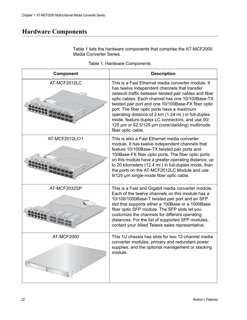
Table 1 lists the hardware components that comprise the AT-MCF2000 Media Converter Series.
Table 1. Hardware Components
Component Description
AT-MCF2012LC This is a Fast Ethernet media converter module. It has twelve independent channels that transfer network traffic between twisted pair cables and fiber optic cables. Each channel has one 10/100Base-TX twisted pair port and one 10/100Base-FX fiber optic port. The fiber optic ports have a maximum operating distance of 2 km (1.24 mi.) in full-duplex mode, feature duplex LC connectors, and use 50/125 µm or 62.5/125 µm (core/cladding) multimode fiber optic cable.
AT-MCF2012LC/1 This is also a Fast Ethernet media converter module. It has twelve independent channels that feature 10/100Base-TX twisted pair ports and 100Base-FX fiber optic ports. The fiber optic ports on this module have a greater operating distance, up to 20 kilometers (12.4 mi.) in full-duplex mode, than the ports on the AT-MCF2012LC Module and use 9/125 µm single-mode fiber optic cable.
AT-MCF2032SP This is a Fast and Gigabit media converter module. Each of the twelve channels on this module has a 10/100/1000Base-T twisted pair port and an SFP slot that supports either a 100Base or a 1000Base fiber optic SFP module. The SFP slots let you customize the channels for different operating distances. For the list of supported SFP modules, contact your Allied Telesis sales representative.
AT-MCF2000 This 1U chassis has slots for two 12-channel media converter modules, primary and redundant power supplies, and the optional management or stacking module.
1390
1390
1389
AT-MCF2000
1
2 1415
AT-MCF2KPNL1
AT-MCF2KPNL1
AT-
MC
F200
0
22 Section I: Features
AT-MCF2000 Media Converter Series Installation Guide
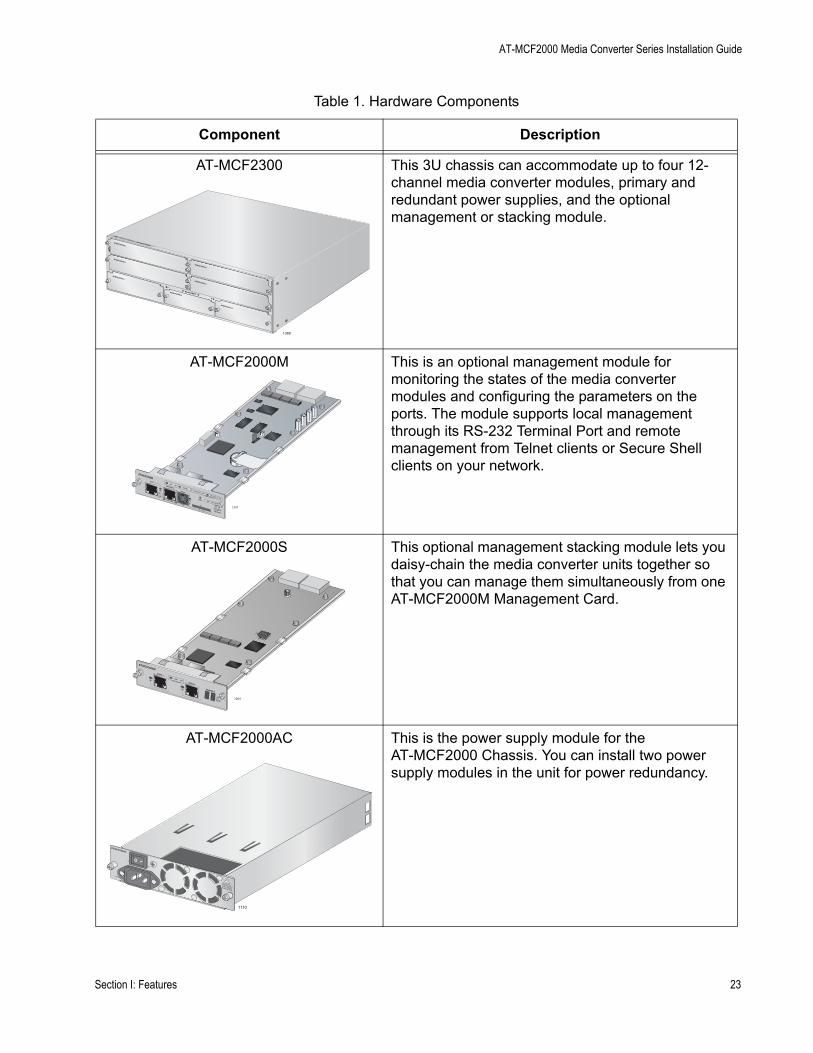
AT-MCF2300 This 3U chassis can accommodate up to four 12-channel media converter modules, primary and redundant power supplies, and the optional management or stacking module.
AT-MCF2000M This is an optional management module for monitoring the states of the media converter modules and configuring the parameters on the ports. The module supports local management through its RS-232 Terminal Port and remote management from Telnet clients or Secure Shell clients on your network.
AT-MCF2000S This optional management stacking module lets you daisy-chain the media converter units together so that you can manage them simultaneously from one AT-MCF2000M Management Card.
AT-MCF2000AC This is the power supply module for the AT-MCF2000 Chassis. You can install two power supply modules in the unit for power redundancy.
Table 1. Hardware Components
Component Description
AT-MCF2000
1388
AT-M
CF2
00
3
4
AT-MCF2KPNL1
AT-MCF2KPNL1
AT-MCF2KPNL2
AT-MCF2KPNL3
MANAGEMENT
A
B
1
2
AT-MCF2KPNL1
AT-MCF2KPNL1
AT-MCF2KPNL2
AT-MCF2000MSTACK
MANAGEMENT
TERMINAL
10/100/1000BASE-T
RS-232
RESET
SD
RDYBUSY
MASTERPOWER
BOOTRDY
FAULT
1000 LINKACT 10/100 LINK
ACT
FDX HDXCOL
LINKACT
PORT ACTIVITY
1391
0
31
ID
AT-MCF2000S
STACK 1
LINKACTPORT ACTIVITY STACK 2
CHASSIS ID
1264
1110
Section I: Features 23

Chapter 1: AT-MCF2000 Multi-channel Media Converter Series
AT-MCF2300AC This is the power supply module for the AT-MCF2300 Chassis. The chassis can accommodate two power modules for redundancy.
AT-MCF2KFAN This is the cooling module for the AT-MCF2000 Chassis. This module is required if the chassis has just one AT-MCF2000AC Power Supply Module.
AT-MCF2300FAN This is the cooling module for the AT-MCF2300 Chassis. It comes preinstalled in the unit.
Table 1. Hardware Components
Component Description
1392
AT-MCF2300AC
1123
AT-MCF2000FAN
FAN 1
FAN 2
FAN 3
1393
24 Section I: Features

AT-MCF2000 Media Converter Series Installation Guide
Management Software Components
Table 2 lists the management software programs of the AT-MCF2000 Media Converter Series.
NoteThe optional AT-MCF2000S Stacking Module does not have management software.
Table 2. Management Software
Management Software Description
AT-S85 This is the management software for the AT-MCF2012LC, AT-MCF2012LC/1 and AT-MCF2032SP Media Converter Modules. It comes preinstalled on the modules and is upgradable with the optional AT-MCF2000M Management Module.
AT-S97 This is the management software for the optional AT-MCF2000M Management Module.
Section I: Features 25

Chapter 1: AT-MCF2000 Multi-channel Media Converter Series
26 Section I: Features
Chapter 2
AT-MCF2000 and AT-MCF2300 Chassis
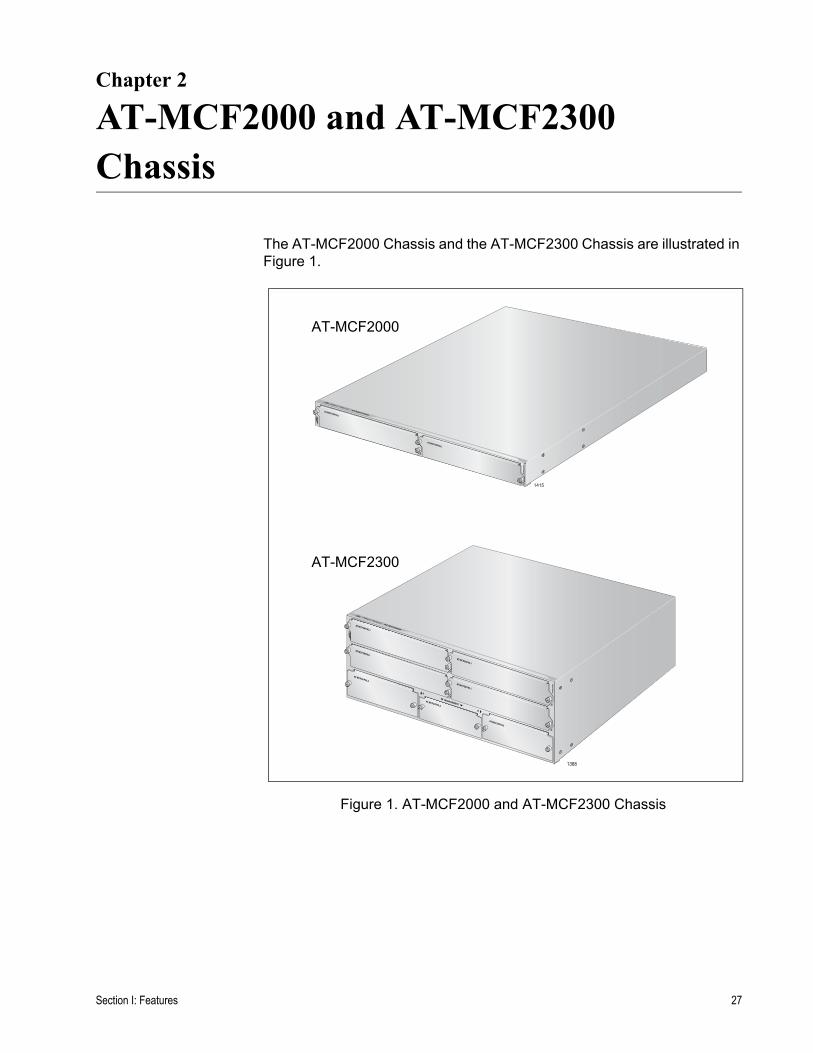
The AT-MCF2000 Chassis and the AT-MCF2300 Chassis are illustrated in Figure 1.
Figure 1. AT-MCF2000 and AT-MCF2300 Chassis
AT-MCF2000
1
2 1415
AT-MCF2KPNL1
AT-MCF2KPNL1
AT-
MC
F20
00
AT-MCF2000
1388
AT-
MC
F200
3
4
AT-MCF2KPNL1
AT-MCF2KPNL1
AT-MCF2KPNL2
AT-MCF2KPNL3
MANAGEMENT
A
B
1
2
AT-MCF2KPNL1
AT-MCF2KPNL1
AT-MCF2KPNL2
AT-MCF2000
AT-MCF2300
Section I: Features 27
Chapter 2: AT-MCF2000 and AT-MCF2300 Chassis
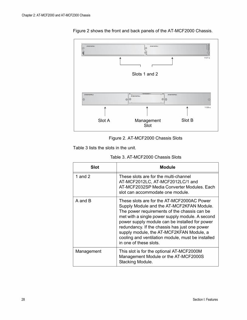
Figure 2 shows the front and back panels of the AT-MCF2000 Chassis.
Figure 2. AT-MCF2000 Chassis Slots
Table 3 lists the slots in the unit.
Table 3. AT-MCF2000 Chassis Slots
Slot Module
1 and 2 These slots are for the multi-channel AT-MCF2012LC, AT-MCF2012LC/1 and AT-MCF2032SP Media Converter Modules. Each slot can accommodate one module.
A and B These slots are for the AT-MCF2000AC Power Supply Module and the AT-MCF2KFAN Module. The power requirements of the chassis can be met with a single power supply module. A second power supply module can be installed for power redundancy. If the chassis has just one power supply module, the AT-MCF2KFAN Module, a cooling and ventilation module, must be installed in one of these slots.
Management This slot is for the optional AT-MCF2000M Management Module or the AT-MCF2000S Stacking Module.
Slots 1 and 2
1107-a
AT-MCF2KPNL1 AT-MCF2KPNL1
1 2
AT-
MC
F20
00
ManagementSlot
Slot A
1108-a
AT-MCF2KPNL2 AT-MCF2KPNL2AT-MCF2KPNL3
MANAGEMENTA B
Slot B
28 Section I: Features
AT-MCF2000 Media Converter Series Installation Guide
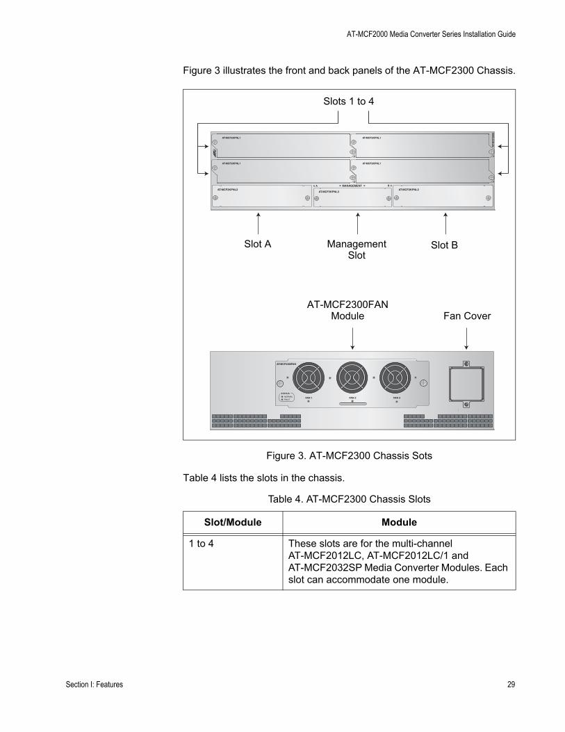
Figure 3 illustrates the front and back panels of the AT-MCF2300 Chassis.
Figure 3. AT-MCF2300 Chassis Sots
Table 4 lists the slots in the chassis.
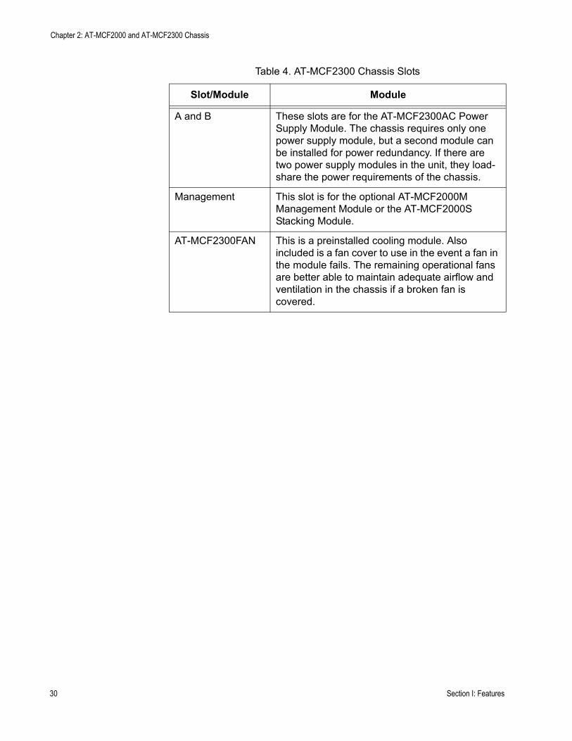
Table 4. AT-MCF2300 Chassis Slots
Slot/Module Module
1 to 4 These slots are for the multi-channel AT-MCF2012LC, AT-MCF2012LC/1 and AT-MCF2032SP Media Converter Modules. Each slot can accommodate one module.
ManagementSlot
Slot A Slot B
Slots 1 to 4
AT-MCF2KPNL1 AT-MCF2KPNL1
1 2
AT-
MC
F20
00
AT-MCF2KPNL1 AT-MCF2KPNL1
3 4
AT-MCF2KPNL3AT-MCF2KPNL2
MANAGEMENTAT-MCF2KPNL2
A B
AT-MCF2300FANModule Fan Cover
FAN 1 FAN 2 FAN 3
STATUSNORMAL
FAULT
AT-MCF2300FAN
Section I: Features 29
Chapter 2: AT-MCF2000 and AT-MCF2300 Chassis
A and B These slots are for the AT-MCF2300AC Power Supply Module. The chassis requires only one power supply module, but a second module can be installed for power redundancy. If there are two power supply modules in the unit, they load-share the power requirements of the chassis.
Management This slot is for the optional AT-MCF2000M Management Module or the AT-MCF2000S Stacking Module.
AT-MCF2300FAN This is a preinstalled cooling module. Also included is a fan cover to use in the event a fan in the module fails. The remaining operational fans are better able to maintain adequate airflow and ventilation in the chassis if a broken fan is covered.
Table 4. AT-MCF2300 Chassis Slots
Slot/Module Module
30 Section I: Features

Chapter 3
AT-MCF2012LC, AT-MCF2012LC/1 and AT-MCF2032SP Modules
This chapter contains the following sections:
❒ “Overview” on page 32❒ “Front Panels” on page 33❒ “Media Converter Channels” on page 34❒ “Twisted Pair Ports” on page 35❒ “Fiber Optic Ports” on page 36❒ “Channel Operating Modes” on page 37❒ “Port and Channel LEDs” on page 41❒ “Mode Button” on page 51❒ “Guidelines to Using the Media Converter Modules” on page 53
Section I: Features 31
Chapter 3: AT-MCF2012LC, AT-MCF2012LC/1 and AT-MCF2032SP Modules
Overview
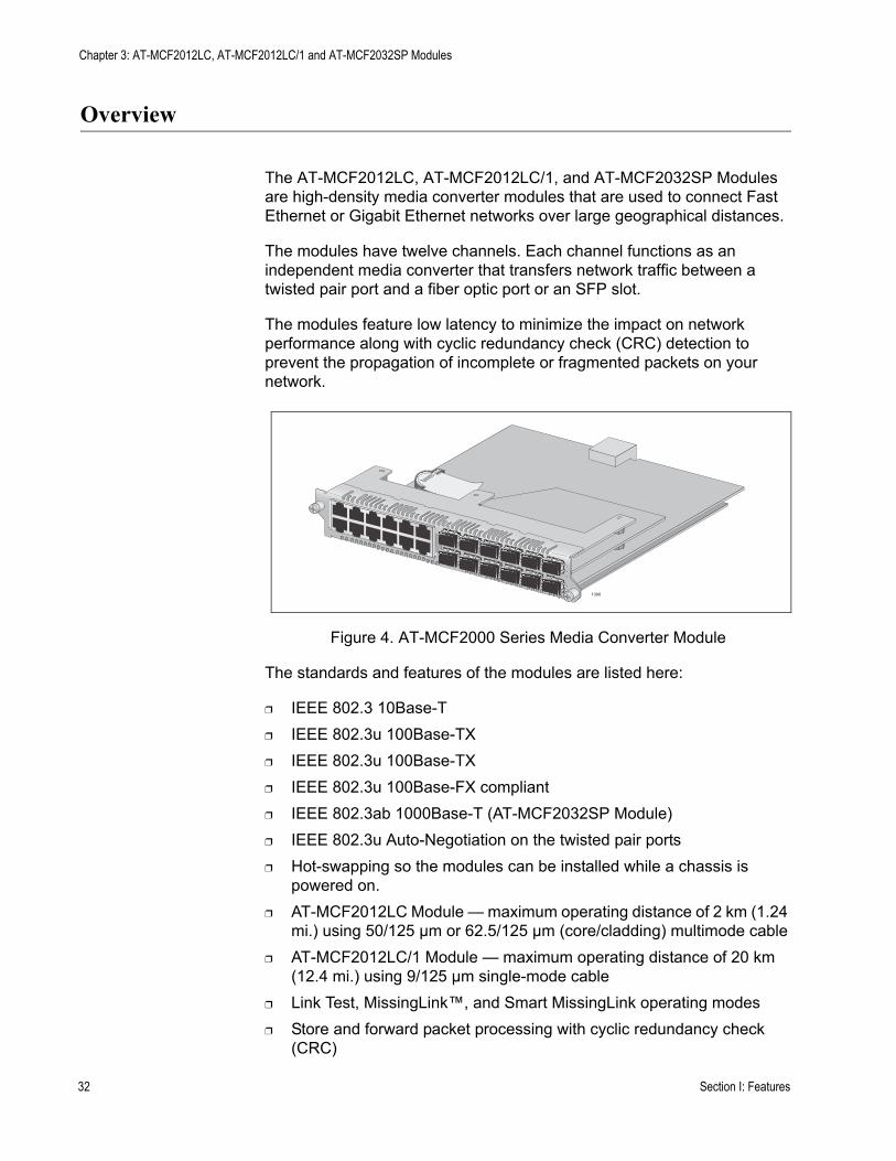
The AT-MCF2012LC, AT-MCF2012LC/1, and AT-MCF2032SP Modules are high-density media converter modules that are used to connect Fast Ethernet or Gigabit Ethernet networks over large geographical distances.
The modules have twelve channels. Each channel functions as an independent media converter that transfers network traffic between a twisted pair port and a fiber optic port or an SFP slot.
The modules feature low latency to minimize the impact on network performance along with cyclic redundancy check (CRC) detection to prevent the propagation of incomplete or fragmented packets on your network.
Figure 4. AT-MCF2000 Series Media Converter Module
The standards and features of the modules are listed here:
❒ IEEE 802.3 10Base-T ❒ IEEE 802.3u 100Base-TX❒ IEEE 802.3u 100Base-TX❒ IEEE 802.3u 100Base-FX compliant❒ IEEE 802.3ab 1000Base-T (AT-MCF2032SP Module)❒ IEEE 802.3u Auto-Negotiation on the twisted pair ports❒ Hot-swapping so the modules can be installed while a chassis is
powered on.❒ AT-MCF2012LC Module — maximum operating distance of 2 km (1.24
mi.) using 50/125 µm or 62.5/125 µm (core/cladding) multimode cable❒ AT-MCF2012LC/1 Module — maximum operating distance of 20 km
(12.4 mi.) using 9/125 µm single-mode cable❒ Link Test, MissingLink™, and Smart MissingLink operating modes❒ Store and forward packet processing with cyclic redundancy check
(CRC)
1390
32 Section I: Features

AT-MCF2000 Media Converter Series Installation Guide
Front Panels
The model names can be found on the left side of the faceplates. Figure 5 shows the front panel of the AT-MCF2012LC Media Converter Module.
Figure 5. Front Panel of the AT-MCF2012LC Module
Figure 6 illustrates the front panel of the AT-MCF2012LC/1 Media Converter Module.
Figure 6. Front Panel of the AT-MCF2012LC/1 Module
Figure 7 illustrates the front panel of the AT-MCF2032SP Media Converter Module.
Figure 7. Front Panel of the AT-MCF2032SP Module
L
A
L
A
CH
CH
CH1
CH2
L
A
L
A
CH3
CH4
L
A
L
A
CH5
CH6
L
A
L
A
CH7
CH8
L
A
L
A
CH9
CH10
L
A
L
A
CH11
CH12
TX RX1
TX RX
TX RX
TX RX2
3
4
5
6
7
8
9
10
11
12CDC FDC
LT ML SML
L A1
L A2
3
4
5
6
7
8
9
10
11
12
L A
L A
AT-
MC
F20
12L
C
CLASS 1LED PRODUCT
1119
L
A
L
A
CH
CH
CH1
CH2
L
A
L
A
CH3
CH4
L
A
L
A
CH5
CH6
L
A
L
A
CH7
CH8
L
A
L
A
CH9
CH10
L
A
L
A
CH11
CH12
TX RX1
TX RX
TX RX
TX RX2
3
4
5
6
7
8
9
10
11
12CDC FDC
LT ML SML
L A1
L A2
3
4
5
6
7
8
9
10
11
12
L A
L A
AT-
MC
F20
12L
C/1
CLASS 1LASER PRODUCT
CH
CH
CDC
FDC
LT
ML
L A1
L A2
3
4
5
6
7
8
9
10
11
12
L A
L A
AT-
MC
F20
32S
P
CLASS 1LASER PRODUCT
SML
1 2 3 4 5 6 7 8 9 10 11 12RDY/FLT HBI HBO
Section I: Features 33
Chapter 3: AT-MCF2012LC, AT-MCF2012LC/1 and AT-MCF2032SP Modules
Media Converter Channels
The media converter modules have twelve independent media converter channels that forward Fast or Gigabit Ethernet network traffic. Each channel has one twisted pair port and one fiber optic port. The channels on the AT-MCF2012LC and AT-MCF2012LC/1 Media Converter Modules have 10/100Base-TX twisted pair ports and 100Base-FX fiber optic ports. In contrast, the channels on the AT-MCF2032SP Media Converter Module have 10/100/1000Base-T twisted pair ports and SFP slots for either 100 Mbps or 1000 Mbps fiber optic SFP modules.
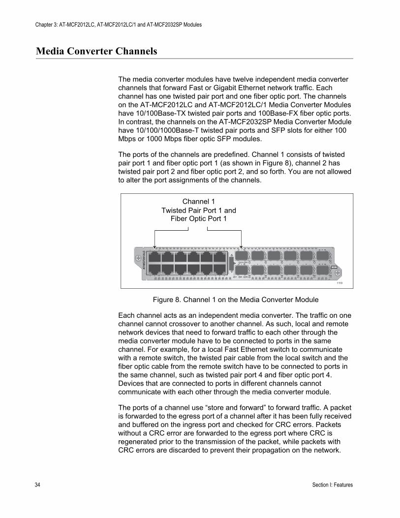
The ports of the channels are predefined. Channel 1 consists of twisted pair port 1 and fiber optic port 1 (as shown in Figure 8), channel 2 has twisted pair port 2 and fiber optic port 2, and so forth. You are not allowed to alter the port assignments of the channels.
Figure 8. Channel 1 on the Media Converter Module
Each channel acts as an independent media converter. The traffic on one channel cannot crossover to another channel. As such, local and remote network devices that need to forward traffic to each other through the media converter module have to be connected to ports in the same channel. For example, for a local Fast Ethernet switch to communicate with a remote switch, the twisted pair cable from the local switch and the fiber optic cable from the remote switch have to be connected to ports in the same channel, such as twisted pair port 4 and fiber optic port 4. Devices that are connected to ports in different channels cannot communicate with each other through the media converter module.
The ports of a channel use “store and forward” to forward traffic. A packet is forwarded to the egress port of a channel after it has been fully received and buffered on the ingress port and checked for CRC errors. Packets without a CRC error are forwarded to the egress port where CRC is regenerated prior to the transmission of the packet, while packets with CRC errors are discarded to prevent their propagation on the network.
Channel 1Twisted Pair Port 1 and
Fiber Optic Port 1
L
A
L
A
CH
CH
CH1
CH2
L
A
L
A
CH3
CH4
L
A
L
A
CH5
CH6
L
A
L
A
CH7
CH8
L
A
L
A
CH9
CH10
L
A
L
A
CH11
CH12
TX RX1
TX RX
TX RX
TX RX2
3
4
5
6
7
8
9
10
11
12CDC FDC
LT ML SML
L A1
L A2
3
4
5
6
7
8
9
10
11
12
L A
L A
AT-
MC
F20
12L
C
CLASS 1LED PRODUCT
1119
34 Section I: Features

AT-MCF2000 Media Converter Series Installation Guide
Twisted Pair Ports
Table 5 lists the cable specifications for the twisted pair ports.
The twisted pair ports feature standard RJ-45 8-pin connectors. For the port pinouts, refer to “Twisted Pair Port Pinouts” on page 174.
The ports are IEEE 802.3u. compliant and use Auto-Negotiation to automatically set their speeds and duplex modes. To adjust the ports manually, you have to use the optional management module.
The twisted pair ports also have auto-MDI/MDI-X, which enables them to automatically adjust their wiring configuration to MDI or MDI-X, depending on the wiring configuration of the end nodes. This allows you to use a straight-through twisted pair cable regardless of the wiring configuration of the ports on the network devices.
The auto-MDI/MDI-X feature is only available when the twisted pair ports are using Auto-Negotiation, the default setting. If you disable Auto-Negotiation on a port and set the speed and duplex mode manually, this feature is also disabled and the port defaults to the MDI-X setting.
Table 5. Twisted Pair Cabling and Distances
Speed Cable TypeMaximum Operating Distance
10 Mbps Standard TIA/EIA 568-B-compliant Category 3 or better shielded or unshielded cabling with 100 ohm impedance and a frequency of 16 MHz.
100 m (328 ft)
100 Mbps Standard TIA/EIA 568-A-compliant Category 5 or TIA/EIA 568-B-compliant Enhanced Category 5 (Cat 5e) shielded or unshielded cabling with 100 ohm impedance and a frequency of 100 MHz.
100 m (328 ft)
1000 Mbps (AT-MCF2032SP only)
Standard TIA/EIA 568-A-compliant Category 5 or TIA/EIA 568-B-compliant Enhanced Category 5 (Cat 5e) shielded or unshielded cabling with 100 ohm impedance and a frequency of 100 MHz.
100 m (328 ft)
Section I: Features 35

Chapter 3: AT-MCF2012LC, AT-MCF2012LC/1 and AT-MCF2032SP Modules
Fiber Optic Ports
Table 6 lists the specifications for the fiber optic cabling for the AT-MCF2012LC and AT-MCF2012LC/1 Media Converter Modules.
NoteThe maximum operating distances in the table assume full-duplex operation. The maximum operating distance of a fiber optic port operating in half-duplex mode will be significantly less.
For the operating specifications of the fiber optic ports on the AT-MCF2012LC and AT-MCF2012LC/1 Modules, refer to “100Base-FX Fiber Optic Ports” on page 175.
For the fiber optic cabling specifications for the AT-MCF2032SP Module, refer to the instructions that come with the SFP modules.
Table 6. Fiber Optic Ports
Media Converter Module Connector
Maximum Operating Distance
Fiber Optic Cable
AT-MCF2012LC Duplex LC 2 km (1.24 mi.) 50/125 µm or 62.5/125 µm (core/cladding) multimode fiber optic cable
AT-MCF2012LC/1 Duplex LC 20 km (12.4 mi.) 9/125 µm single-mode fiber optic cable
36 Section I: Features

AT-MCF2000 Media Converter Series Installation Guide
Channel Operating Modes
The media converter channels support these operating modes:
❒ Link Test mode❒ MissingLink mode❒ Smart MissingLink mode
The operating modes of the channels are set with the Mode button on the front panel of the module explained in “Mode Button” on page 51, or with the optional management module. These operating modes, which, during normal network operations, do not interfere with the flow of traffic through the ports of the channels, can be used to alert you when a port loses its link to a network device or to troubleshoot a network problem.
Link Test Mode Contrary to its name, the Link Test operating mode is not a diagnostic utility. Rather, it simply displays on the Link LEDs the states of the links of the two ports in a channel. When a channel is operating in this mode, a Link LED will be on when a port has established a link to its network device, and it will be off when a port does not have a link. (Refer to Table 8 on page 44.)
This mode, as with all of the operating modes, does not interfere with the flow of traffic between the two ports of a channel during normal network operations. It is typically used when the network devices connected to a channel cannot take advantage of the features of the MissingLink mode, or when you want to use the Link LEDs to troubleshoot a link problem. This operating mode is also useful after you have installed a media converter module and want to verify whether the ports of the channels have successfully established links with the local and remote network devices. This is explained in “AT-MCF2012LC, AT-MCF2012LC/1 and AT-MCF2032SP Media Converter Modules” on page 141 in Chapter 21, “Verifying the Installation”.
MissingLinkMode
The MissingLink mode enables the twisted pair port and the fiber optic port of a channel to pass the “Link” status of their connections to each other. This ensures that both ports of a channel and, consequently, the network devices connected to the ports, are aware of any changes to the state of the link on the companion port.
When a channel in the MissingLink mode detects the loss of a link on one of the ports, it disables the transmitter on the companion port to notify the network device connected to it of the loss of the link on the other channel port. Without the MissingLink mode, a network device connected to a port on the media converter would not be aware of a loss of a link on a companion port in the channel, because its link to the media converter would be unaffected.
Section I: Features 37

Chapter 3: AT-MCF2012LC, AT-MCF2012LC/1 and AT-MCF2032SP Modules
When the link is reestablished on a port of a channel, the MissingLink mode automatically reactivates the transmitter on the companion port so that the two network devices can again forward traffic to each other through the two ports of the media converter channel.
The value to this type of fault notification is that some network devices, such as managed Fast Ethernet switches, can respond to the loss of a link on a port by performing a specific action. For example, the network device might send a trap to a network management station, and so alert the network administrator of the problem. Or, if the device is running a spanning tree protocol, it might seek a redundant path to a disconnected node.
Here is an example of how the MissingLink mode works. Assume that the two ports of a channel are connected to two Fast Ethernet switches, one local and the other remote. Switch A, the local switch, is connected to the twisted pair port of the channel, while Switch B, the remote device, is connected to the fiber optic port. If the link to Switch A is lost on the twisted pair cable, the media converter disables the transmitter on the fiber optic port in the same channel to signal Switch B of the loss of the link to Switch A. This notifies Switch B of the problem so that it too, along with Switch A, can take remedial action, such as activating a redundant path if it is running a spanning tree protocol or sending an SNMP trap to a management workstation if it is using SNMP. Without the MissingLink mode, Switch B would assume that it still had a valid link to the remote device on the other side of the media converter channel since its link to the port on the channel is still valid, even though no remote traffic is received.
In the example, the initial loss of a link in a channel occurred on the twisted pair port. But the mode operates in the same fashion when the initial loss of a link is on the fiber optic port. Here, the mode disables the transmitter on the twisted pair port to notify the node connected to that port of the loss of the link on the fiber optic port.
The Link LEDs of the ports in a channel that are running in this mode always operate in tandem, as shown in Table 9 on page 45. They are both on or off. Both Link LEDs of the ports of a channel remain off until both ports can establish links with their network devices.
This operating mode is primarily used on a channel when the network devices can react to the loss of a link on a port, such as managed Fast Ethernet switches that are running a spanning tree protocol. Conversely, the MissingLink mode should not be used on a channel if the two ports are connected to network devices that cannot react to a lost link. Instead, you might set the channel to the Link Test mode.
Furthermore, Allied Telesis does not recommend using the MissingLink mode when you’re trying to troubleshoot a network problem that might have its roots with a link problem. This is because the MissingLink mode does not allow you to use the Link LEDs of the ports in a channel to
38 Section I: Features

AT-MCF2000 Media Converter Series Installation Guide
diagnose the problem. Rather, you should use the Link Test or the Smart MissingLink modes to troubleshoot a link problem.
SmartMissingLink
Mode
The Smart MissingLink mode, the third operating mode of the media converter channels, is nearly identical to the MissingLink mode. It, too, enables the ports of a channel to pass the “Link” status of their connections to each other so that both ports reflect the same link status.
The difference is that when a port in a channel loses its link to its network device, this mode does not completely shut off the transmitter on the companion port. Rather, it pulses the port’s transmitter and blinks the port’s Link LED every second. This signals that the port can still establish a link to its network device and that the loss of the link originated on the other port in the channel.
This difference allows you to use the Link LEDs of the ports to troubleshoot a link failure. In contrast, when a channel is operating in the MissingLink mode you cannot use the Link LEDs of the ports to troubleshoot a link problem because both LEDs will be off when one port does not have a link to its network device.
For definitions of the Link LEDs when a channel is operating in this mode, refer to Table 10 on page 45.
Here is an example of how the Smart MissingLink mode works. Assume that the fiber optic port in a media converter channel lost its link to its network device while the channel was in the Smart MissingLink operating mode. The mode would respond by pulsing the transmitter on the twisted pair port of the channel about once a second, and flashing the port’s Link LED. This would signal that the twisted pair port can still establish a link with its network device and that the failure originated on the fiber optic port. When the connection is reestablished on the fiber optic port, the twisted pair port resumes normal operations so that the two ports can again forward traffic to each other.
The operating mode functions the same if the failure starts on the twisted pair port in a channel. Here, the mode pulses the transmitter on the fiber optic port and blinks the port’s Link LED.
As with the other two channel operating modes, this mode does not interfere with the flow of network traffic through the ports of a channel during normal network operations. However, you might want to limit its use to diagnosing a link failure, particularly if the network devices connected to the ports are managed devices. This is because the pulsing of the transmitter on a port and the constantly changing status of a link could prove problematic for some managed devices. For example, the device might send a constant stream of SNMP traps or, if the device is running a spanning tree protocol, the protocol may become confused as the status of the device’s link to the media converter constantly changes.
Section I: Features 39

Chapter 3: AT-MCF2012LC, AT-MCF2012LC/1 and AT-MCF2032SP Modules
Guidelines toUsing theChannel
Operating Modes
Here are the guidelines to using the channel operating modes:
❒ The channels on a module can be set to different operating modes.❒ The operating modes do not block or interfere with the flow of traffic
between the two ports of a channel during normal network operations.❒ The MissingLink mode is intended for situations where the devices
that are connected to the ports of a channel are able to react to the loss of a link by performing a specific action, such as sending out SNMP traps.
❒ Allied Telesis does not recommend using the Smart MissingLink mode on a channel that is connected to managed devices. As explained in “Smart MissingLink Mode” on page 39, this mode responds to the loss of a link on a port in a channel by pulsing the transmitter of the companion port. A pulsing transmitter may cause problems for a managed device.
❒ The Link Test and Smart MissingLink modes are particularly useful after a link failure on a channel port because they allow you to use the Link LEDs to determine whether or not the ports have established links with their network devices.
❒ You set the operating modes of the channels with the Mode button as explained in “Mode Button” on page 51 or with the optional AT-MCF2000M Management Module.
40 Section I: Features
AT-MCF2000 Media Converter Series Installation Guide
Port and Channel LEDs
The LEDs on a media converter module reflect packet activity, link status, duplex mode and collisions of the ports, as well as the operating modes of the channels.
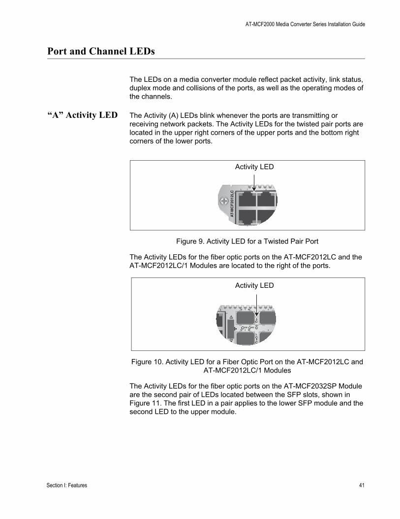
“A” Activity LED The Activity (A) LEDs blink whenever the ports are transmitting or receiving network packets. The Activity LEDs for the twisted pair ports are located in the upper right corners of the upper ports and the bottom right corners of the lower ports.
Figure 9. Activity LED for a Twisted Pair Port
The Activity LEDs for the fiber optic ports on the AT-MCF2012LC and the AT-MCF2012LC/1 Modules are located to the right of the ports.
Figure 10. Activity LED for a Fiber Optic Port on the AT-MCF2012LC and AT-MCF2012LC/1 Modules
The Activity LEDs for the fiber optic ports on the AT-MCF2032SP Module are the second pair of LEDs located between the SFP slots, shown in Figure 11. The first LED in a pair applies to the lower SFP module and the second LED to the upper module.
Activity LED
L A1
L A2
3
4
AT-
MC
F20
12L
C
Activity LED
L
A
L
A
CH
CH
CH1
CH2
TX RX1
TX RX2
3
4CDC FDC
A
Section I: Features 41

Chapter 3: AT-MCF2012LC, AT-MCF2012LC/1 and AT-MCF2032SP Modules
Figure 11. Activity LEDs for the Fiber Optic Ports on the AT-MCF2032SP Module
The Activity LED is defined in Table 7.
“L” Link LEDs The ports have Link LEDs which typically report whether or not the ports have established links to the network devices. However, the meanings of the LEDs can vary depending on the operating modes of the channels.
To understand the meanings of the Link LEDs of a channel, you first need to determine a channel’s operating mode. You can do this using the management module or the LT, ML, and SML LEDs and the Mode button on the front panel of a module. It can also be useful to consider the Link LEDs of the two ports of a channel as a pair and to view them as a unit.
The meanings of the Link LEDs are described in the following subsections. There is a different subsection for each operating mode.
The Link LEDs for the twisted pair ports are located in the upper left corners of the upper ports and the bottom left corners of the lower ports, as shown in Figure 12.
Figure 12. Link LED for a Twisted Pair Port
Table 7. “A” Activity LED
Link LED State Description
Off A port is not receiving or transmitting network packets.
Flashing Green A port is receiving or transmitting packets.
Activity LEDs
CH
CH
CDC
FDC
LT
ML
SML
Link LED
L A1
L A2
3
4
AT-
MC
F20
12L
C
42 Section I: Features
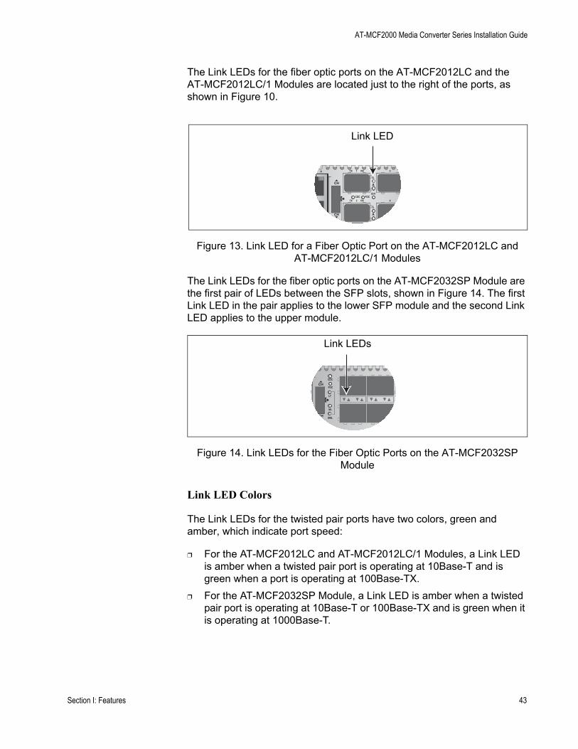
AT-MCF2000 Media Converter Series Installation Guide
The Link LEDs for the fiber optic ports on the AT-MCF2012LC and the AT-MCF2012LC/1 Modules are located just to the right of the ports, as shown in Figure 10.
Figure 13. Link LED for a Fiber Optic Port on the AT-MCF2012LC and AT-MCF2012LC/1 Modules
The Link LEDs for the fiber optic ports on the AT-MCF2032SP Module are the first pair of LEDs between the SFP slots, shown in Figure 14. The first Link LED in the pair applies to the lower SFP module and the second Link LED applies to the upper module.
Figure 14. Link LEDs for the Fiber Optic Ports on the AT-MCF2032SP Module
Link LED Colors
The Link LEDs for the twisted pair ports have two colors, green and amber, which indicate port speed:
❒ For the AT-MCF2012LC and AT-MCF2012LC/1 Modules, a Link LED is amber when a twisted pair port is operating at 10Base-T and is green when a port is operating at 100Base-TX.
❒ For the AT-MCF2032SP Module, a Link LED is amber when a twisted pair port is operating at 10Base-T or 100Base-TX and is green when it is operating at 1000Base-T.
Link LED
L
A
L
A
CH
CH
CH1
CH2
TX RX1
TX RX2
3
4CDC FDC
A
Link LEDs
CH
CH
CDC
FDC
LT
ML
SML
Section I: Features 43
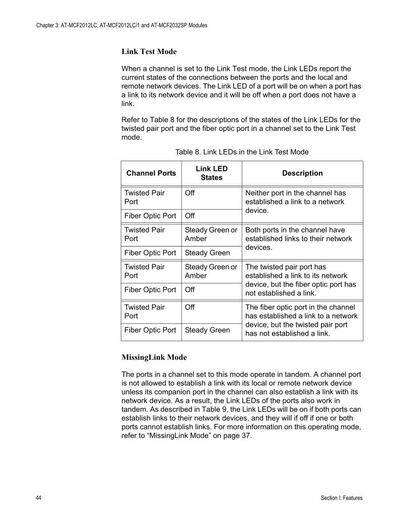
Chapter 3: AT-MCF2012LC, AT-MCF2012LC/1 and AT-MCF2032SP Modules
Link Test Mode
When a channel is set to the Link Test mode, the Link LEDs report the current states of the connections between the ports and the local and remote network devices. The Link LED of a port will be on when a port has a link to its network device and it will be off when a port does not have a link.
Refer to Table 8 for the descriptions of the states of the Link LEDs for the twisted pair port and the fiber optic port in a channel set to the Link Test mode.
MissingLink Mode
The ports in a channel set to this mode operate in tandem. A channel port is not allowed to establish a link with its local or remote network device unless its companion port in the channel can also establish a link with its network device. As a result, the Link LEDs of the ports also work in tandem. As described in Table 9, the Link LEDs will be on if both ports can establish links to their network devices, and they will if off if one or both ports cannot establish links. For more information on this operating mode, refer to “MissingLink Mode” on page 37.
Table 8. Link LEDs in the Link Test Mode
Channel Ports Link LED States Description
Twisted Pair Port
Off Neither port in the channel has established a link to a network device.
Fiber Optic Port Off
Twisted Pair Port
Steady Green or Amber
Both ports in the channel have established links to their network devices.
Fiber Optic Port Steady Green
Twisted Pair Port
Steady Green or Amber
The twisted pair port has established a link to its network device, but the fiber optic port has not established a link.Fiber Optic Port Off
Twisted Pair Port
Off The fiber optic port in the channel has established a link to a network device, but the twisted pair port has not established a link.Fiber Optic Port Steady Green
44 Section I: Features
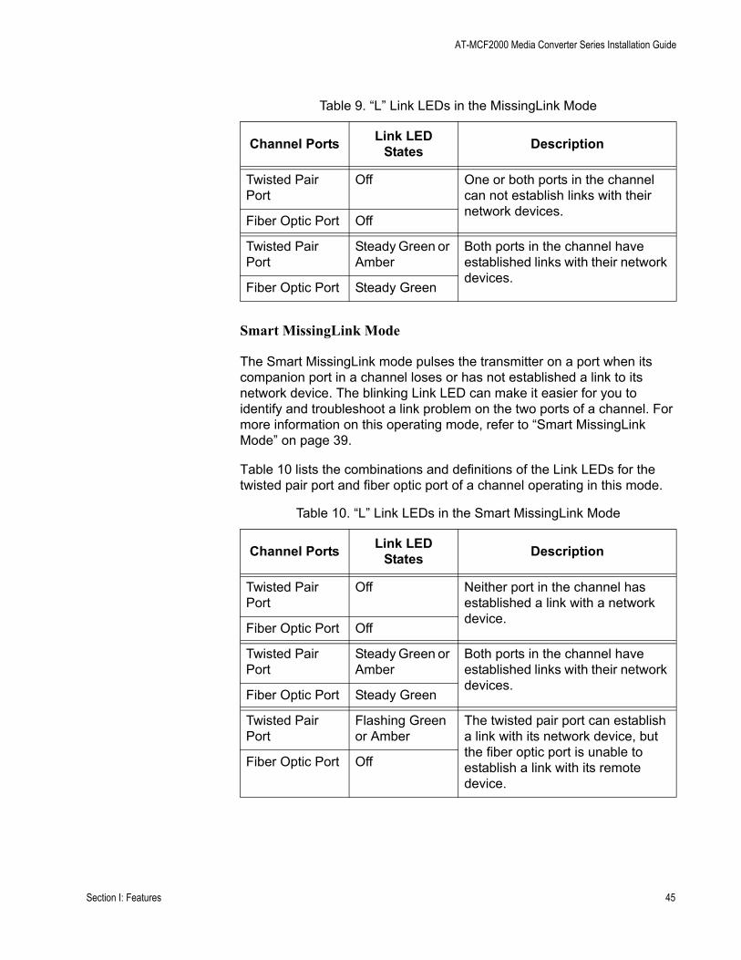
AT-MCF2000 Media Converter Series Installation Guide
Smart MissingLink Mode
The Smart MissingLink mode pulses the transmitter on a port when its companion port in a channel loses or has not established a link to its network device. The blinking Link LED can make it easier for you to identify and troubleshoot a link problem on the two ports of a channel. For more information on this operating mode, refer to “Smart MissingLink Mode” on page 39.
Table 10 lists the combinations and definitions of the Link LEDs for the twisted pair port and fiber optic port of a channel operating in this mode.
Table 9. “L” Link LEDs in the MissingLink Mode
Channel Ports Link LED States Description
Twisted Pair Port
Off One or both ports in the channel can not establish links with their network devices.
Fiber Optic Port Off
Twisted Pair Port
Steady Green or Amber
Both ports in the channel have established links with their network devices.
Fiber Optic Port Steady Green
Table 10. “L” Link LEDs in the Smart MissingLink Mode
Channel Ports Link LED States Description
Twisted Pair Port
Off Neither port in the channel has established a link with a network device.
Fiber Optic Port Off
Twisted Pair Port
Steady Green or Amber
Both ports in the channel have established links with their network devices.
Fiber Optic Port Steady Green
Twisted Pair Port
Flashing Green or Amber
The twisted pair port can establish a link with its network device, but the fiber optic port is unable to establish a link with its remote device.
Fiber Optic Port Off
Section I: Features 45
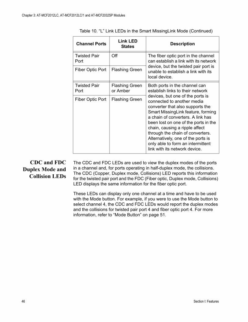
Chapter 3: AT-MCF2012LC, AT-MCF2012LC/1 and AT-MCF2032SP Modules
CDC and FDCDuplex Mode and
Collision LEDs
The CDC and FDC LEDs are used to view the duplex modes of the ports in a channel and, for ports operating in half-duplex mode, the collisions. The CDC (Copper, Duplex mode, Collisions) LED reports this information for the twisted pair port and the FDC (Fiber optic, Duplex mode, Collisions) LED displays the same information for the fiber optic port.
These LEDs can display only one channel at a time and have to be used with the Mode button. For example, if you were to use the Mode button to select channel 4, the CDC and FDC LEDs would report the duplex modes and the collisions for twisted pair port 4 and fiber optic port 4. For more information, refer to “Mode Button” on page 51.
Twisted Pair Port
Off The fiber optic port in the channel can establish a link with its network device, but the twisted pair port is unable to establish a link with its local device.
Fiber Optic Port Flashing Green
Twisted Pair Port
Flashing Green or Amber
Both ports in the channel can establish links to their network devices, but one of the ports is connected to another media converter that also supports the Smart MissingLink feature, forming a chain of converters. A link has been lost on one of the ports in the chain, causing a ripple affect through the chain of converters.Alternatively, one of the ports is only able to form an intermittent link with its network device.
Fiber Optic Port Flashing Green
Table 10. “L” Link LEDs in the Smart MissingLink Mode (Continued)
Channel Ports Link LED States Description
46 Section I: Features
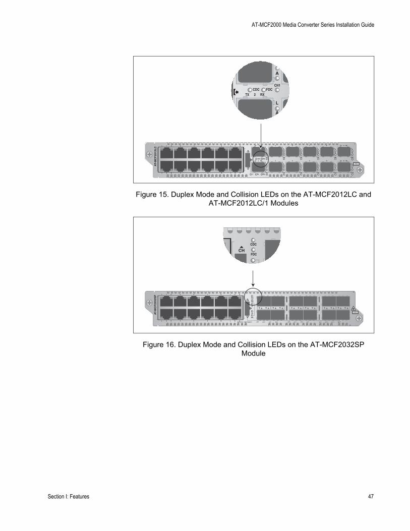
AT-MCF2000 Media Converter Series Installation Guide
Figure 15. Duplex Mode and Collision LEDs on the AT-MCF2012LC and AT-MCF2012LC/1 Modules
Figure 16. Duplex Mode and Collision LEDs on the AT-MCF2032SP Module
L
A
L
A
CH
CH
CH1
CH2
L
A
L
A
CH3
CH4
L
A
L
A
CH5
CH6
L
A
L
A
CH7
CH8
L
A
L
A
CH9
CH10
L
A
L
A
CH11
CH12
TX RX1
TX RX
TX RX
TX RX2
3
4
5
6
7
8
9
10
11
12CDC FDC
LT ML SML
L A1
L A2
3
4
5
6
7
8
9
10
11
12
L A
L A
AT-
MC
F20
12L
C
CLASS 1LED PRODUCT
L
A
L
A
CH1
TX RX2CDC FDC
CH
CDC
FDC
CH
CH
CDC
FDC
LT
ML
L A1
L A2
3
4
5
6
7
8
9
10
11
12
L A
L A
AT-
MC
F20
32S
P
CLASS 1LASER PRODUCT
SML
1 2 3 4 5 6 7 8 9 10 11 12RDY/FLT HBI HBO
Section I: Features 47

Chapter 3: AT-MCF2012LC, AT-MCF2012LC/1 and AT-MCF2032SP Modules
The CDC and FDC LEDs are described in Table 11.
LT, ML, andSML Channel
Operating ModeLEDs
Figure 17 and Figure 18 show the locations of the LT, ML, and SML LEDs. You use these LEDs to determine the operating modes of the channels on the module. You can view the operating mode of just one channel at a time with these LEDs. You select the channel with the Mode button, explained in “Mode Button” on page 51. The operating modes are Link Test (LT), MissingLink (ML), and Smart MissingLink (SML).
Figure 17. Channel Operating Mode LEDs on the AT-MCF2012LC and AT-MCF2012LC/1 Modules
Table 11. CDC and FDC Duplex Mode and Collisions LEDs
LED State Description
CDC Off The twisted pair port in the channel has not established a link with its network device.
Steady Green The twisted pair port is operating in full-duplex mode.
Steady Amber The twisted pair port is operating in half-duplex mode.
Flashing Amber Collisions are occurring on the twisted pair port.
FDC Off The fiber optic port in the channel has not established a link with its network device.
Steady Green The fiber optic port is operating in full-duplex mode.
Steady Amber The fiber optic port is operating in half-duplex mode.
Flashing Amber Collisions are occurring on the fiber optic port.
L
A
L
A
CH
CH
CH1
CH2
L
A
L
A
CH3
CH4
L
A
L
A
CH5
CH6
L
A
L
A
CH7
CH8
L
A
L
A
CH9
CH10
L
A
L
A
CH11
CH12
TX RX1
TX RX
TX RX
TX RX2
3
4
5
6
7
8
9
10
11
12CDC FDC
LT ML SML
L A1
L A2
3
4
5
6
7
8
9
10
11
12
L A
L A
AT-
MC
F20
12L
C
CLASS 1LED PRODUCT
L
AH
CH2LT ML SML
48 Section I: Features
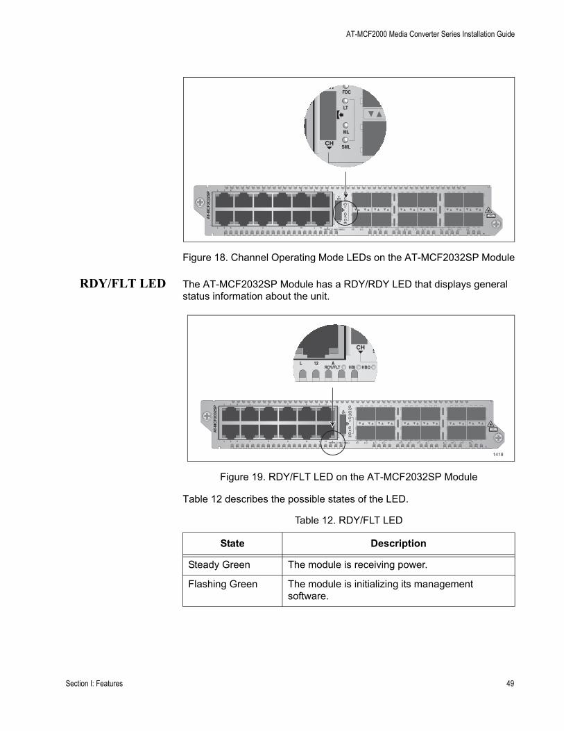
AT-MCF2000 Media Converter Series Installation Guide
Figure 18. Channel Operating Mode LEDs on the AT-MCF2032SP Module
RDY/FLT LED The AT-MCF2032SP Module has a RDY/RDY LED that displays general status information about the unit.
Figure 19. RDY/FLT LED on the AT-MCF2032SP Module
Table 12 describes the possible states of the LED.
CH
CH
FDC
LT
ML
SML
CH
CH
CDC
FDC
LT
ML
L A1
L A2
3
4
5
6
7
8
9
10
11
12
L A
L A
AT-
MC
F20
32S
P
CLASS 1LASER PRODUCT
SML
1 2 3 4 5 6 7 8 9 10 11 12RDY/FLT HBI HBO
Table 12. RDY/FLT LED
State Description
Steady Green The module is receiving power.
Flashing Green The module is initializing its management software.
CH
CH
CDC
FDC
LT
ML
L A1
L A2
3
4
5
6
7
8
9
10
11
12
L A
L A
AT-
MC
F20
32S
P
CLASS 1LASER PRODUCT
SML
1 2 3 4 5 6 7 8 9 10 11 12RDY/FLT HBI HBO
CH
M
12L A
SM
RDY/FLT HBI HBO
1418
Section I: Features 49
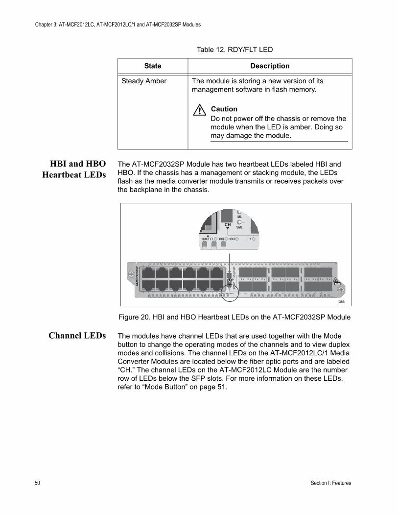
Chapter 3: AT-MCF2012LC, AT-MCF2012LC/1 and AT-MCF2032SP Modules
HBI and HBOHeartbeat LEDs
The AT-MCF2032SP Module has two heartbeat LEDs labeled HBI and HBO. If the chassis has a management or stacking module, the LEDs flash as the media converter module transmits or receives packets over the backplane in the chassis.
Figure 20. HBI and HBO Heartbeat LEDs on the AT-MCF2032SP Module
Channel LEDs The modules have channel LEDs that are used together with the Mode button to change the operating modes of the channels and to view duplex modes and collisions. The channel LEDs on the AT-MCF2012LC/1 Media Converter Modules are located below the fiber optic ports and are labeled “CH.” The channel LEDs on the AT-MCF2012LC Module are the number row of LEDs below the SFP slots. For more information on these LEDs, refer to “Mode Button” on page 51.
Steady Amber The module is storing a new version of its management software in flash memory.
CautionDo not power off the chassis or remove the module when the LED is amber. Doing so may damage the module.
Table 12. RDY/FLT LED
State Description
CH
CH
CDC
FDC
LT
ML
L A1
L A2
3
4
5
6
7
8
9
10
11
12
L A
L A
AT-
MC
F20
32S
P
CLASS 1LASER PRODUCT
SML
1 2 3 4 5 6 7 8 9 10 11 12RDY/FLT HBI HBO
CH
ML
A
SML
1RDY/FLT HBI HBO
1386
50 Section I: Features
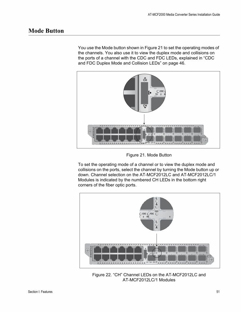
AT-MCF2000 Media Converter Series Installation Guide
Mode Button
You use the Mode button shown in Figure 21 to set the operating modes of the channels. You also use it to view the duplex mode and collisions on the ports of a channel with the CDC and FDC LEDs, explained in “CDC and FDC Duplex Mode and Collision LEDs” on page 46.
Figure 21. Mode Button
To set the operating mode of a channel or to view the duplex mode and collisions on the ports, select the channel by turning the Mode button up or down. Channel selection on the AT-MCF2012LC and AT-MCF2012LC/1 Modules is indicated by the numbered CH LEDs in the bottom right corners of the fiber optic ports.
Figure 22. “CH” Channel LEDs on the AT-MCF2012LC and AT-MCF2012LC/1 Modules
L
A
L
A
CH
CH
CH1
CH2
L
A
L
A
CH3
CH4
L
A
L
A
CH5
CH6
L
A
L
A
CH7
CH8
L
A
L
A
CH9
CH10
L
A
L
A
CH11
CH12
TX RX1
TX RX
TX RX
TX RX2
3
4
5
6
7
8
9
10
11
12CDC FDC
LT ML SML
L A1
L A2
3
4
5
6
7
8
9
10
11
12
L A
L A
AT-
MC
F20
12L
C
CLASS 1LED PRODUCT
CH
CH
TX RX2CDC
L
A
L
A
CH
CH
CH1
CH2
L
A
L
A
CH3
CH4
L
A
L
A
CH5
CH6
L
A
L
A
CH7
CH8
L
A
L
A
CH9
CH10
L
A
L
A
CH11
CH12
TX RX1
TX RX
TX RX
TX RX2
3
4
5
6
7
8
9
10
11
12CDC FDC
LT ML SML
L A1
L A2
3
4
5
6
7
8
9
10
11
12
L A
L A
AT-
MC
F20
12L
C
CLASS 1LED PRODUCT
L
A
L
A
CH1
X RX2 4CDC FDC
Section I: Features 51
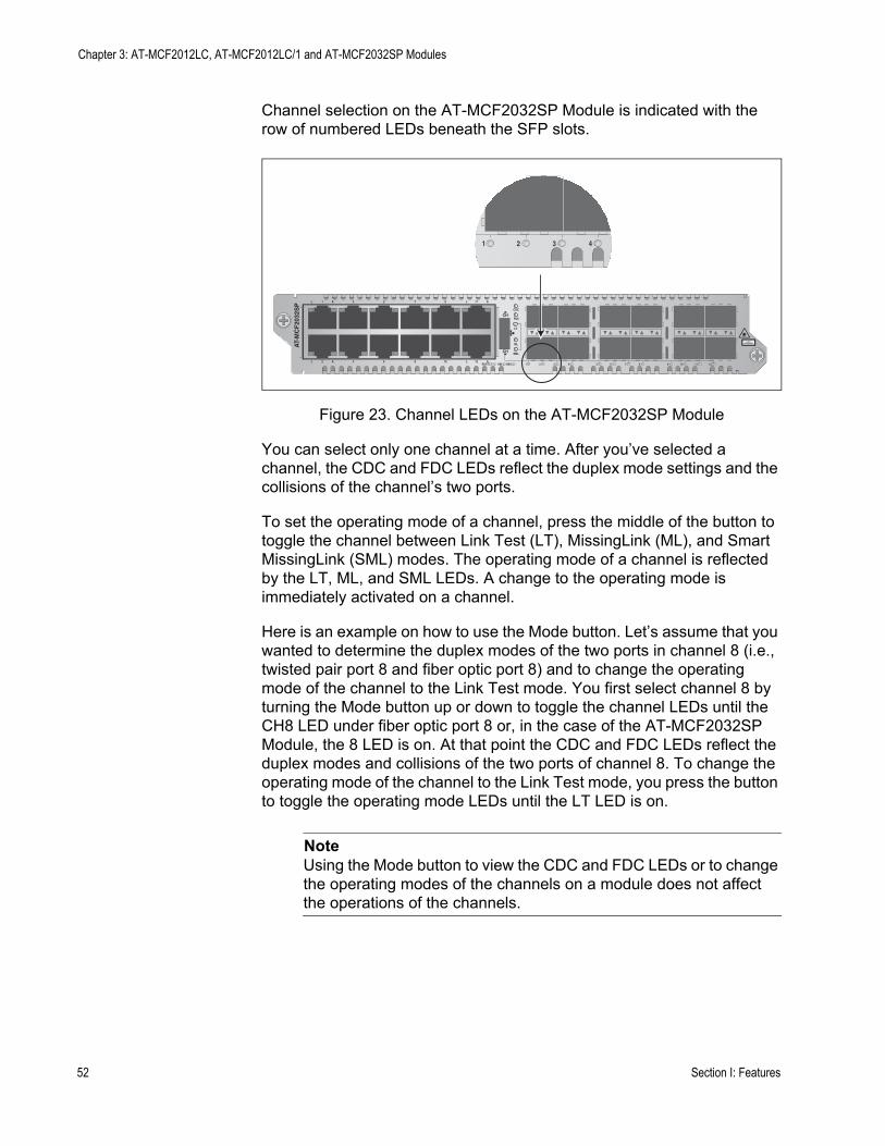
Chapter 3: AT-MCF2012LC, AT-MCF2012LC/1 and AT-MCF2032SP Modules
Channel selection on the AT-MCF2032SP Module is indicated with the row of numbered LEDs beneath the SFP slots.
Figure 23. Channel LEDs on the AT-MCF2032SP Module
You can select only one channel at a time. After you’ve selected a channel, the CDC and FDC LEDs reflect the duplex mode settings and the collisions of the channel’s two ports.
To set the operating mode of a channel, press the middle of the button to toggle the channel between Link Test (LT), MissingLink (ML), and Smart MissingLink (SML) modes. The operating mode of a channel is reflected by the LT, ML, and SML LEDs. A change to the operating mode is immediately activated on a channel.
Here is an example on how to use the Mode button. Let’s assume that you wanted to determine the duplex modes of the two ports in channel 8 (i.e., twisted pair port 8 and fiber optic port 8) and to change the operating mode of the channel to the Link Test mode. You first select channel 8 by turning the Mode button up or down to toggle the channel LEDs until the CH8 LED under fiber optic port 8 or, in the case of the AT-MCF2032SP Module, the 8 LED is on. At that point the CDC and FDC LEDs reflect the duplex modes and collisions of the two ports of channel 8. To change the operating mode of the channel to the Link Test mode, you press the button to toggle the operating mode LEDs until the LT LED is on.
NoteUsing the Mode button to view the CDC and FDC LEDs or to change the operating modes of the channels on a module does not affect the operations of the channels.
CH
CH
CDC
FDC
LT
ML
L A1
L A2
3
4
5
6
7
8
9
10
11
12
L A
L A
AT-
MC
F20
32S
P
CLASS 1LASER PRODUCT
SML
1 2 3 4 5 6 7 8 9 10 11 12RDY/FLT HBI HBO
1 2 3 4
52 Section I: Features

AT-MCF2000 Media Converter Series Installation Guide
Guidelines to Using the Media Converter Modules
Here are the guidelines to using the AT-MCF2012LC, AT-MCF2012LC/1, and AT-MCF2032SP Media Converter Modules.
❒ In order for two network devices to forward traffic to each other through the media converter module, the twisted pair cable from the local device and the fiber optic cable from the remote device have to be attached to ports in the same channel. As explained in “Media Converter Channels” on page 34, the ports of the channels are predefined. Channel 1 consists of twisted pair port 1 and fiber optic port 1, channel 2 of twisted pair port 2 and fiber optic port 2, and so forth.
❒ You cannot change the port assignments of the channels.❒ You can use the media converter channels in any order.❒ The twisted pair port and the fiber optic port of a channel can operate
at different speeds, provided that the local and remote network devices use backpressure or flow control, depending on the duplex mode, to control the flow of traffic.
❒ A media converter channel performs best when its two ports and the local and remote network devices operate with the same duplex mode, either half- or full-duplex.
❒ The default setting for the twisted pair ports on the media converter modules is Auto-Negotiation and auto-MDI/MDI-X.
❒ The default duplex mode setting for the fiber optic ports is full-duplex.❒ Changing the settings of the ports on the media converter modules
requires the optional management module.❒ There are no adjustable switches on the circuit boards of the
AT-MCF2012LC, AT-MCF2012LC/1, and AT-MCF2032SP Media Converter Modules.
Section I: Features 53

Chapter 3: AT-MCF2012LC, AT-MCF2012LC/1 and AT-MCF2032SP Modules
54 Section I: Features

Chapter 4
AT-MCF2000M Management Module
This chapter describes the optional AT-MCF2000M Management Module:
❒ “Overview” on page 56❒ “Front Panel” on page 58❒ “10/100/1000Base-T Management Port” on page 59❒ “RS-232 Terminal Port” on page 61❒ “Stack Port” on page 62❒ “Reset Button” on page 63❒ “SD Slot” on page 65❒ “Chassis ID Jumper” on page 66❒ “LEDs” on page 67
Section I: Features 55
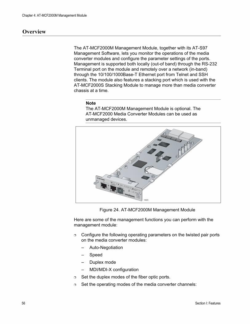
Chapter 4: AT-MCF2000M Management Module
Overview
The AT-MCF2000M Management Module, together with its AT-S97 Management Software, lets you monitor the operations of the media converter modules and configure the parameter settings of the ports. Management is supported both locally (out-of band) through the RS-232 Terminal port on the module and remotely over a network (in-band) through the 10/100/1000Base-T Ethernet port from Telnet and SSH clients. The module also features a stacking port which is used with the AT-MCF2000S Stacking Module to manage more than media converter chassis at a time.
NoteThe AT-MCF2000M Management Module is optional. The AT-MCF2000 Media Converter Modules can be used as unmanaged devices.
Figure 24. AT-MCF2000M Management Module
Here are some of the management functions you can perform with the management module:
❒ Configure the following operating parameters on the twisted pair ports on the media converter modules:– Auto-Negotiation– Speed– Duplex mode– MDI/MDI-X configuration
❒ Set the duplex modes of the fiber optic ports.❒ Set the operating modes of the media converter channels:
AT-MCF2000MSTACK
MANAGEMENT
TERMINAL
10/100/1000BASE-T
RS-232
RESET
SD
RDYBUSY
MASTERPOWER
BOOTRDY
FAULT
1000 LINKACT 10/100 LINK
ACT
FDX HDXCOL
LINKACT
PORT ACTIVITY
1423
0
31
ID
56 Section I: Features
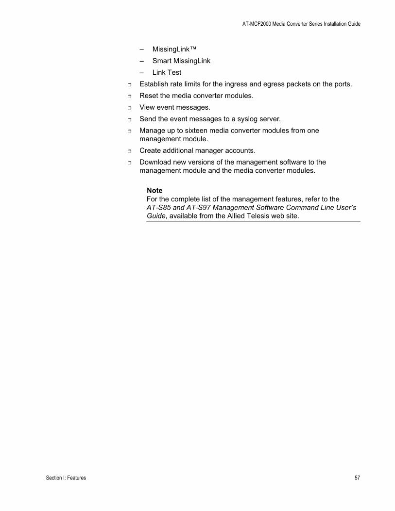
AT-MCF2000 Media Converter Series Installation Guide
– MissingLink™– Smart MissingLink– Link Test
❒ Establish rate limits for the ingress and egress packets on the ports.❒ Reset the media converter modules.❒ View event messages.❒ Send the event messages to a syslog server.❒ Manage up to sixteen media converter modules from one
management module.❒ Create additional manager accounts.❒ Download new versions of the management software to the
management module and the media converter modules.
NoteFor the complete list of the management features, refer to the AT-S85 and AT-S97 Management Software Command Line User’s Guide, available from the Allied Telesis web site.
Section I: Features 57

Chapter 4: AT-MCF2000M Management Module
Front Panel
Figure 25 illustrates the front panel of the AT-MCF2000M Management Module.
Figure 25. Front Panel of the AT-MCF2000M Management Module
The components on the front panel are described here:
❒ Stack port -This port is used to connect multiple chassis together so they can be managed from one management module. For further information, refer to Chapter 5, “AT-MCF2000S Stacking Module” on page 73.
❒ 10/100/1000Base-T Management Port - This is a standard Ethernet, Fast Ethernet, and Gigabit Ethernet port. The module uses this port for management functions that require communications with your network, like remote (in-band) management from a Telnet or Secure Shell (SSH) client and file transfers to or from a TFTP server. For further information, refer to “10/100/1000Base-T Management Port” on page 59.
❒ RS-232 Terminal port - You use this port for local (out-of-band) management of the chassis. For further information, refer to “RS-232 Terminal Port” on page 61.
❒ Reset button - This button is used to perform a soft reset of the module. It initializes the AT-S97 Management Software. For further information, refer to “Reset Button” on page 63.
❒ SD slot - This slot is for a secure digital memory card for storing or transferring configuration files. For further information, refer to “SD Slot” on page 65.
AT-MCF2000MSTACK MANAGEMENT
TERMINAL
10/100/1000BASE-T RS-232
RESET
SD
RDY BUSY
MASTER
POWER
BOOT RDY FAULT
1000 LINK ACT 10/100 LINK ACT FDX HDX COLLINK ACTPORT ACTIVITY
1421
SYSTEM
ID31
0
58 Section I: Features

AT-MCF2000 Media Converter Series Installation Guide
10/100/1000Base-T Management Port
The 10/100/1000Base-T Management port is a standard Ethernet, Fast Ethernet, and Gigabit Ethernet port that is used by the module to communicate with your network. You have to connect this port to a device on your network, such as a Fast Ethernet or Gigabit Ethernet switch, if the module will be performing any of these management functions:
❒ Remote management using the Telnet or Secure Shell (SSH) application protocol
❒ Uploading or downloading files to its file system using a TFTP server.❒ Setting its date and time from a Network Time Protocol (NTP) server.❒ Sending events to a syslog server.❒ Obtaining an IP address configuration from a DHCP or BOOTP server.❒ Sending or receiving TCP/IP ping requests from network devices.❒ Sending Simple Network Management Protocol (SNMP) traps to an
SNMP management program.
The port has a standard RJ-45 8-pin connector and can operate at 10, 100, or 1000 Mbps in either half- or full-duplex mode. The cable requirements for the port are listed in Table 13. For the port pinouts, refer to “10/100/1000Base-T Port Pin-outs” on page 176.
The default setting for the Management port is Auto-Negotiation with auto-MDI/MDI-X. At the default setting, the port, which is IEEE 802.3u compliant, sets its speed and duplex mode automatically with Auto-Negotiation. You can disable Auto-Negotiation and set the speed and duplex mode manually.
Table 13. Cable Requirements for the 10/100/1000Base-T Management Port
Speed Cable Type Maximum Operating Distance
10 Mbps Standard TIA/EIA 568-B-compliant Category 3 or better shielded or unshielded cabling with 100 ohm impedance and a frequency of 16 MHz.
100 m (328 ft)
100 or 1000 Mbps
Standard TIA/EIA 568-B-compliant Enhanced Category 5 (Cat 5e) shielded or unshielded cabling with 100 ohm impedance and a frequency of 100 MHz.
100 m (328 ft)
Section I: Features 59

Chapter 4: AT-MCF2000M Management Module
The wiring configuration of the port is set automatically with auto-MDI/MDI-X to either MDI or MDI-X, depending on the wiring configuration of the end node. This allows you to use a straight-through twisted pair cable regardless of the wiring configuration of the port on the network device. The auto-MDI/MDI-X feature is only available when the port is using Auto-Negotiation. This feature is disabled and the port defaults to the MDI-X setting if you disable Auto-Negotiation and set the port’s speed and duplex mode manually.
60 Section I: Features

AT-MCF2000 Media Converter Series Installation Guide
RS-232 Terminal Port
You use this port for local management of the module with a console or a PC with a terminal emulation program. This management method, which does not require the module to have an Internet Protocol (IP) address, is referred to as local or out-of-band management because it is not conducted over a network.
This type of management uses the RS-232 Serial Management cable that comes with the management module. For instructions on how to start a local session, refer to Chapter 22, “Starting a Local Management Session” on page 143 or the AT-S85 and AT-S97 Management Software Command Line User’s Guide.
Section I: Features 61

Chapter 4: AT-MCF2000M Management Module
Stack Port
You use the Stack port to connect the chassis to another chassis that has the AT-MCF2000S Stacking Module so that you can manage the units simultaneously. For background information, refer to Chapter 5, “AT-MCF2000S Stacking Module” on page 73.
62 Section I: Features
AT-MCF2000 Media Converter Series Installation Guide
Reset Button
The Reset button on the front panel of the management module is used to initialize the AT-S97 Management Software and the active master configuration file. Here are situations where you might want to reset the module:
❒ If you select a new active master configuration file and want to reconfigure the modules in the chassis or stack according to the settings in the file. For background information, refer to the AT-S85 and AT-S97 Management Software Command Line User’s Guide.
❒ If the management module is experiencing a problem.
NoteThe management module will be unresponsive to management commands for about one minute while it initializes the AT-S97 Management Software. To determine when the module has completed the initialization process, view the general status LEDs on the module. For information, refer to “General Status LEDs” on page 67.
NoteChanges to the parameter settings of the management module (for example, IP configuration, name, Telnet server status, etc.) that have not been saved to the active master configuration file are discarded when you reset the management module. To save your changes, establish a local or remote management session with the management module and issue the BOOT CONFIG-FILE SAVE command. For more information, refer to the AT-S85 and AT-S97 Management Software Command Line User’s Guide.
To prevent someone from accidentally resetting the management module, the Reset button is recessed in the module. To press the button, use a pointed object, such as the tip of a pen as shown in Figure 26 on page 64, or the end of a straightened paper clip.
Section I: Features 63

Chapter 4: AT-MCF2000M Management Module
Figure 26. Pressing the Reset Button
1203b
AT-MCF2000MSTACK
MANAGEMENT
TERMINAL
10/100/1000BASE-T
RS-232
RESET
SD
RDYBUSY
MASTERPOWER
BOOTRDY
FAULT
1000 LINKACT 10/100 LINK
ACT
FDX HDXCOL
LINKACT
PORT ACTIVITY AT-MCF2KFAN
NORMALFAULT
STATUS
64 Section I: Features
AT-MCF2000 Media Converter Series Installation Guide
SD Slot
The SD slot is for a secure digital memory card, which is used in the following situations:
❒ Storing backup copies of the master configuration file on the management module - You can maintain a library of past configuration files of a chassis or stack so that you can return a unit to a previous configuration.
❒ Transferring master configuration files between chassis - You can configure units that are to have similar configurations by transferring the master configuration file with a secure digital memory card.
A secure digital memory card is optional. The management module can operate without a memory card.
For information on using a secure digital memory card with the management module, refer to the AT-S85 and AT-S97 Management Software Command Line Interface User’s Guide.
NoteThe management module supports 128 MB, 256 MB, and 512 MB secure digital memory cards from Allied Telesis. For ordering information, contact your Allied Telesis sales representative or visit our web site.
NoteDo not remove a secure digital memory card from the management module when the slot’s L/A LED is amber. Wait for the LED to change to green before removing the card.
Section I: Features 65
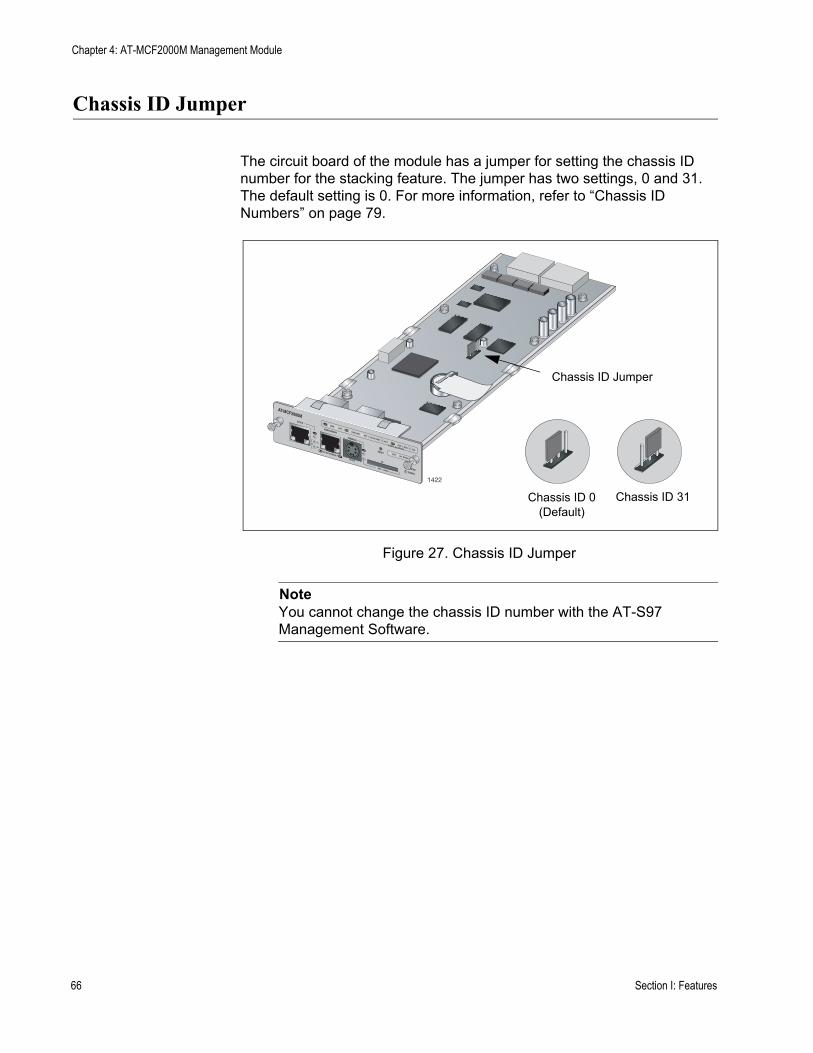
Chapter 4: AT-MCF2000M Management Module
Chassis ID Jumper
The circuit board of the module has a jumper for setting the chassis ID number for the stacking feature. The jumper has two settings, 0 and 31. The default setting is 0. For more information, refer to “Chassis ID Numbers” on page 79.
Figure 27. Chassis ID Jumper
NoteYou cannot change the chassis ID number with the AT-S97 Management Software.
AT-MCF2000MSTACK
MANAGEMENT
TERMINAL
10/100/1000BASE-T
RS-232
RESET
SD
RDYBUSY
MASTERPOWER
BOOTRDY
FAULT
1000 LINKACT 10/100 LINK
ACT
FDX HDXCOL
LINKACT
PORT ACTIVITY
1422
0
31
ID
Chassis ID 0 (Default)
Chassis ID 31
Chassis ID Jumper
66 Section I: Features
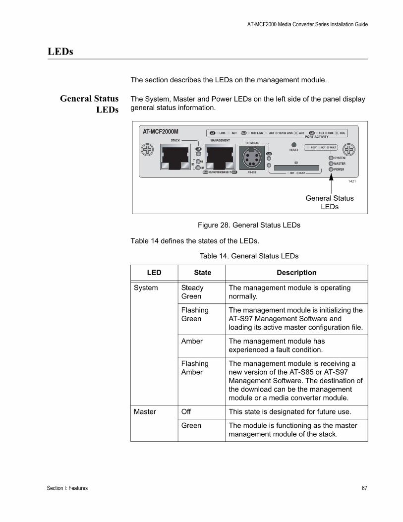
AT-MCF2000 Media Converter Series Installation Guide
LEDs
The section describes the LEDs on the management module.
General StatusLEDs
The System, Master and Power LEDs on the left side of the panel display general status information.
Figure 28. General Status LEDs
Table 14 defines the states of the LEDs.
Table 14. General Status LEDs
LED State Description
System Steady Green
The management module is operating normally.
Flashing Green
The management module is initializing the AT-S97 Management Software and loading its active master configuration file.
Amber The management module has experienced a fault condition.
Flashing Amber
The management module is receiving a new version of the AT-S85 or AT-S97 Management Software. The destination of the download can be the management module or a media converter module.
Master Off This state is designated for future use.
Green The module is functioning as the master management module of the stack.
AT-MCF2000MSTACK MANAGEMENT
TERMINAL
10/100/1000BASE-T RS-232
RESET
SD
RDY BUSY
MASTER
POWER
BOOT RDY FAULT
1000 LINK ACT 10/100 LINK ACT FDX HDX COLLINK ACTPORT ACTIVITY
1421
SYSTEM
ID31
0
General Status LEDs
Section I: Features 67
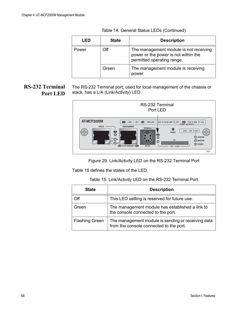
Chapter 4: AT-MCF2000M Management Module
RS-232 TerminalPort LED
The RS-232 Terminal port, used for local management of the chassis or stack, has a L/A (Link/Activity) LED.
Figure 29. Link/Activity LED on the RS-232 Terminal Port
Table 15 defines the states of the LED.
Power Off The management module is not receiving power or the power is not within the permitted operating range.
Green The management module is receiving power.
Table 14. General Status LEDs (Continued)
LED State Description
Table 15. Link/Activity LED on the RS-232 Terminal Port
State Description
Off This LED setting is reserved for future use.
Green The management module has established a link to the console connected to the port.
Flashing Green The management module is sending or receiving data from the console connected to the port.
AT-MCF2000MSTACK MANAGEMENT
TERMINAL
10/100/1000BASE-T RS-232
RESET
SD
RDY BUSY
MASTER
POWER
BOOT RDY FAULT
1000 LINK ACT 10/100 LINK ACT FDX HDX COLLINK ACTPORT ACTIVITY
1421
SYSTEM
ID31
0
RS-232 TerminalPort LED
68 Section I: Features
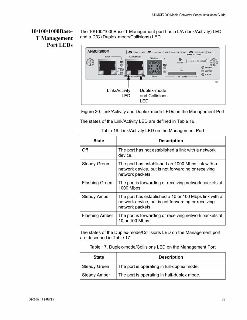
AT-MCF2000 Media Converter Series Installation Guide
10/100/1000Base-T Management
Port LEDs
The 10/100/1000Base-T Management port has a L/A (Link/Activity) LED and a D/C (Duplex-mode/Collisions) LED.
Figure 30. Link/Activity and Duplex-mode LEDs on the Management Port
The states of the Link/Activity LED are defined in Table 16.
The states of the Duplex-mode/Collisions LED on the Management port are described in Table 17.
Table 16. Link/Activity LED on the Management Port
State Description
Off The port has not established a link with a network device.
Steady Green The port has established an 1000 Mbps link with a network device, but is not forwarding or receiving network packets.
Flashing Green The port is forwarding or receiving network packets at 1000 Mbps.
Steady Amber The port has established a 10 or 100 Mbps link with a network device, but is not forwarding or receiving network packets.
Flashing Amber The port is forwarding or receiving network packets at 10 or 100 Mbps.
Table 17. Duplex-mode/Collisions LED on the Management Port
State Description
Steady Green The port is operating in full-duplex mode.
Steady Amber The port is operating in half-duplex mode.
AT-MCF2000MSTACK MANAGEMENT
TERMINAL
10/100/1000BASE-T RS-232
RESET
SD
RDY BUSY
MASTER
POWER
BOOT RDY FAULT
1000 LINK ACT 10/100 LINK ACT FDX HDX COLLINK ACTPORT ACTIVITY
1421
SYSTEM
ID31
0
Link/ActivityLED
Duplex-mode and Collisions LED
Section I: Features 69

Chapter 4: AT-MCF2000M Management Module
ID LEDs The two ID LEDs are used to identify the module’s chassis ID number. This number, which, as explained in “Chassis ID Jumper” on page 66, is set with the jumper on the board and is used in the management commands to identify the chassis. A management module can have the value 0 or 31. If the ID LED 0 is on, the module and the chassis have the ID number 0. If the ID LED 31 is on, then the module and chassis have the ID number 31.
Figure 31. Chassis ID Number LEDs
Stack Port LED The L/A (Link/Activity) LED on the Stack port is shown in Figure 32.
Figure 32. Link/Activity LED on the Stack Port
Flashing Amber The port is operating in half-duplex mode with collisions.
Table 17. Duplex-mode/Collisions LED on the Management Port
State Description
AT-MCF2000MSTACK MANAGEMENT
TERMINAL
10/100/1000BASE-T RS-232
RESET
SD
RDY BUSY
MASTER
POWER
BOOT RDY FAULT
1000 LINK ACT 10/100 LINK ACT FDX HDX COLLINK ACTPORT ACTIVITY
1421
SYSTEM
ID31
0
Chassis ID LEDs
AT-MCF2000MSTACK MANAGEMENT
TERMINAL
10/100/1000BASE-T RS-232
RESET
SD
RDY BUSY
MASTER
POWER
BOOT RDY FAULT
1000 LINK ACT 10/100 LINK ACT FDX HDX COLLINK ACTPORT ACTIVITY
1421
SYSTEM
ID31
0
Link/Activity LED
70 Section I: Features
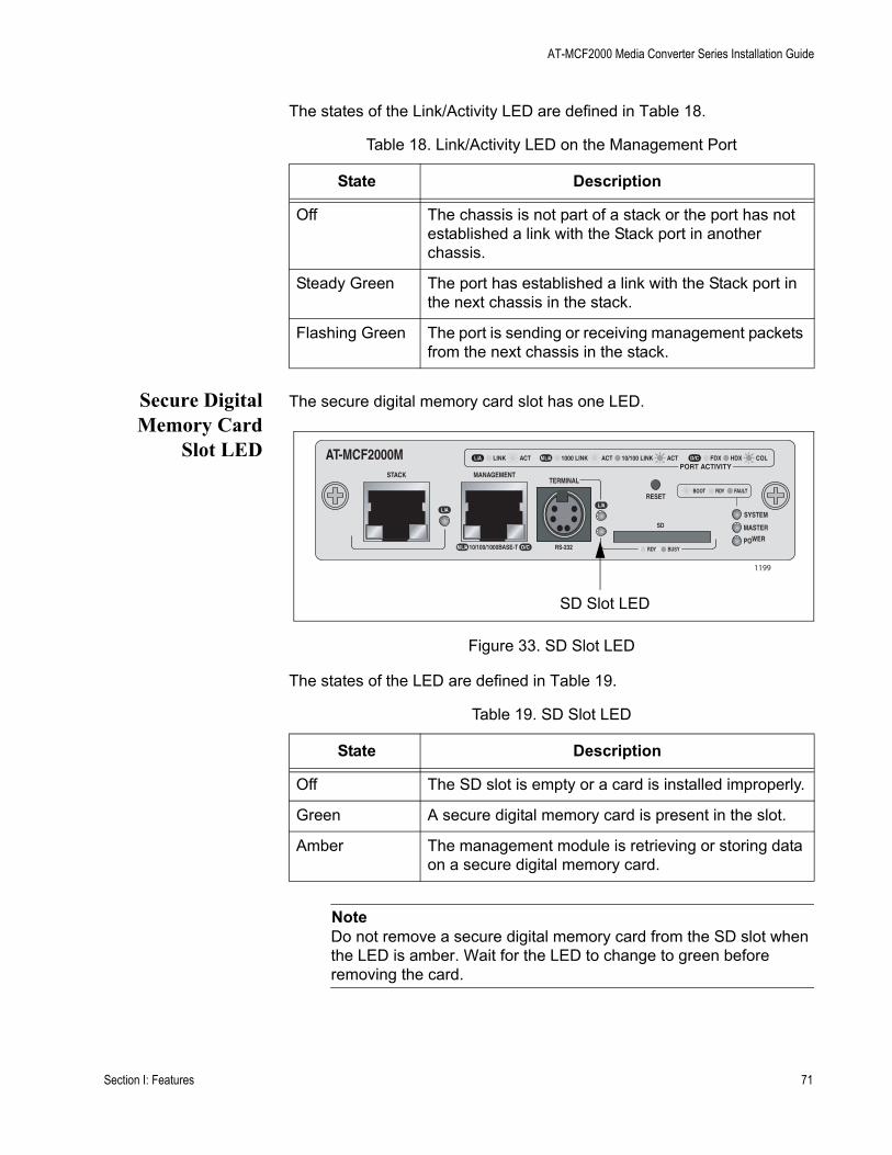
AT-MCF2000 Media Converter Series Installation Guide
The states of the Link/Activity LED are defined in Table 18.
Secure DigitalMemory Card
Slot LED
The secure digital memory card slot has one LED.
Figure 33. SD Slot LED
The states of the LED are defined in Table 19.
NoteDo not remove a secure digital memory card from the SD slot when the LED is amber. Wait for the LED to change to green before removing the card.
Table 18. Link/Activity LED on the Management Port
State Description
Off The chassis is not part of a stack or the port has not established a link with the Stack port in another chassis.
Steady Green The port has established a link with the Stack port in the next chassis in the stack.
Flashing Green The port is sending or receiving management packets from the next chassis in the stack.
Table 19. SD Slot LED
State Description
Off The SD slot is empty or a card is installed improperly.
Green A secure digital memory card is present in the slot.
Amber The management module is retrieving or storing data on a secure digital memory card.
AT-MCF2000MSTACK MANAGEMENT
TERMINAL
10/100/1000BASE-T RS-232
RESET
SD
RDY BUSY
MASTER
POWER
BOOT RDY FAULT
1000 LINK ACT 10/100 LINK ACT FDX HDX COLLINK ACTPORT ACTIVITY
1199
SYSTEM
SD Slot LED
Section I: Features 71

Chapter 4: AT-MCF2000M Management Module
72 Section I: Features

Chapter 5
AT-MCF2000S Stacking Module
This chapter describes the optional AT-MCF2000S Stacking Module. The sections in the chapter are:
❒ “Overview” on page 74❒ “Topology” on page 75❒ “Maximum Number of Media Converter Modules in a Stack” on
page 76❒ “Cabling the Stack Ports” on page 77❒ “Chassis ID Numbers” on page 79❒ “LEDs” on page 81❒ “Chassis ID LEDs” on page 82❒ “Guidelines to Building a Stack” on page 83
Section I: Features 73
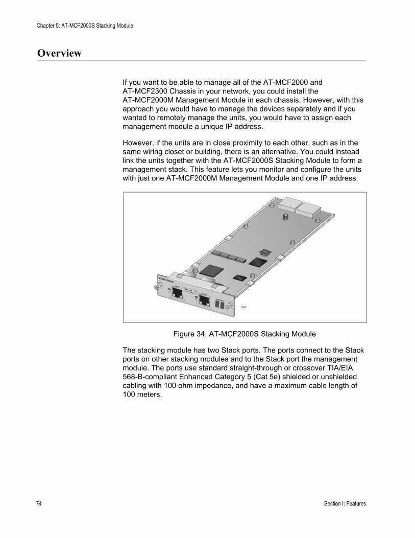
Chapter 5: AT-MCF2000S Stacking Module
Overview
If you want to be able to manage all of the AT-MCF2000 and AT-MCF2300 Chassis in your network, you could install the AT-MCF2000M Management Module in each chassis. However, with this approach you would have to manage the devices separately and if you wanted to remotely manage the units, you would have to assign each management module a unique IP address.
However, if the units are in close proximity to each other, such as in the same wiring closet or building, there is an alternative. You could instead link the units together with the AT-MCF2000S Stacking Module to form a management stack. This feature lets you monitor and configure the units with just one AT-MCF2000M Management Module and one IP address.
Figure 34. AT-MCF2000S Stacking Module
The stacking module has two Stack ports. The ports connect to the Stack ports on other stacking modules and to the Stack port the management module. The ports use standard straight-through or crossover TIA/EIA 568-B-compliant Enhanced Category 5 (Cat 5e) shielded or unshielded cabling with 100 ohm impedance, and have a maximum cable length of 100 meters.
AT-MCF2000S
STACK 1
LINKACTPORT ACTIVITY STACK 2
CHASSIS ID
1264
74 Section I: Features
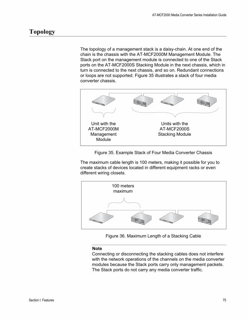
AT-MCF2000 Media Converter Series Installation Guide
Topology
The topology of a management stack is a daisy-chain. At one end of the chain is the chassis with the AT-MCF2000M Management Module. The Stack port on the management module is connected to one of the Stack ports on the AT-MCF2000S Stacking Module in the next chassis, which in turn is connected to the next chassis, and so on. Redundant connections or loops are not supported. Figure 35 illustrates a stack of four media converter chassis.
Figure 35. Example Stack of Four Media Converter Chassis
The maximum cable length is 100 meters, making it possible for you to create stacks of devices located in different equipment racks or even different wiring closets.
Figure 36. Maximum Length of a Stacking Cable
NoteConnecting or disconnecting the stacking cables does not interfere with the network operations of the channels on the media converter modules because the Stack ports carry only management packets. The Stack ports do not carry any media converter traffic.
Unit with theAT-MCF2000MManagement
Module
Units with theAT-MCF2000S
Stacking Module
100 metersmaximum
Section I: Features 75

Chapter 5: AT-MCF2000S Stacking Module
Maximum Number of Media Converter Modules in a Stack
The maximum size of a stack is based on the number of media converter modules and not on the number of enclosures. The maximum number of media converter modules a stack can have is sixteen. When building a stack, count the total number of media converter slots in the units.
For example, the maximum size of a stack of the AT-MCF2000 Chassis, which has two slots for media converter modules, is eight enclosures:
8 AT-MCF2000 Chassis x 2 slots = 16 media converter modules
In contrast, the maximum size of a stack of the AT-MCF2300 Chassis, which has slots for four media converter modules, is four units:
4 AT-MCF2300 Chassis x 4 slots =16 media converter modules
A stack can have both types of chassis. For example, you might create a stack of four AT-MCF2000 Chassis and two AT-MCF2300 Chassis:
(4 AT-MCF2000 Chassis x 2 slots) + (2 AT-MCF2300 Chassis x 4 slots) = 16 media converter modules
76 Section I: Features

AT-MCF2000 Media Converter Series Installation Guide
Cabling the Stack Ports
Table 20 contains the specifications for the cable for the Stack ports on the management and stacking modules.
To cable the Stack ports, connect the Stack port on the AT-MCF2000M Management Module to either of the Stack ports on the AT-MCF2000S Stacking Module in the next chassis.
Figure 37. Cabling the AT-MCF2000M Management Module to the AT-MCF2000S Stacking Module
Table 20. Cable Requirements for the Stack Ports
Cable Type Maximum Operating Distance
Standard straight-through or crossover TIA/EIA 568-B-compliant Enhanced Category 5 (Cat 5e) shielded or unshielded cabling with 100 ohm impedance.
100 m (328 ft)
AT-MCF2000SLINK ACT
PORT ACTIVITYSTACK 1 STACK 2
AT-MCF2000SLINK ACT
PORT ACTIVITYSTACK 1 STACK 2
AT-MCF2000MSTACK MANAGEMENT
TERMINAL
10/100/1000BASE-T RS-232
RESET
SD
RDY BUSY
MASTER
POWER
BOOT RDY FAULT
1000 LINK ACT 10/100 LINK ACT FDX HDX COLLINK ACTPORT ACTIVITY
SYSTEM
0
31ID
AT-MCF2000MSTACK MANAGEMENT
TERMINAL
10/100/1000BASE-T RS-232
RESET
SD
RDY BUSY
MASTER
POWER
BOOT RDY FAULT
1000 LINK ACT 10/100 LINK ACT FDX HDX COLLINK ACTPORT ACTIVITY
SYSTEM
0
31ID
CHASSIS ID
CHASSIS ID
1259
OR
AT-MCF2000M ManagementModule
AT-MCF2000S StackingModule
Section I: Features 77
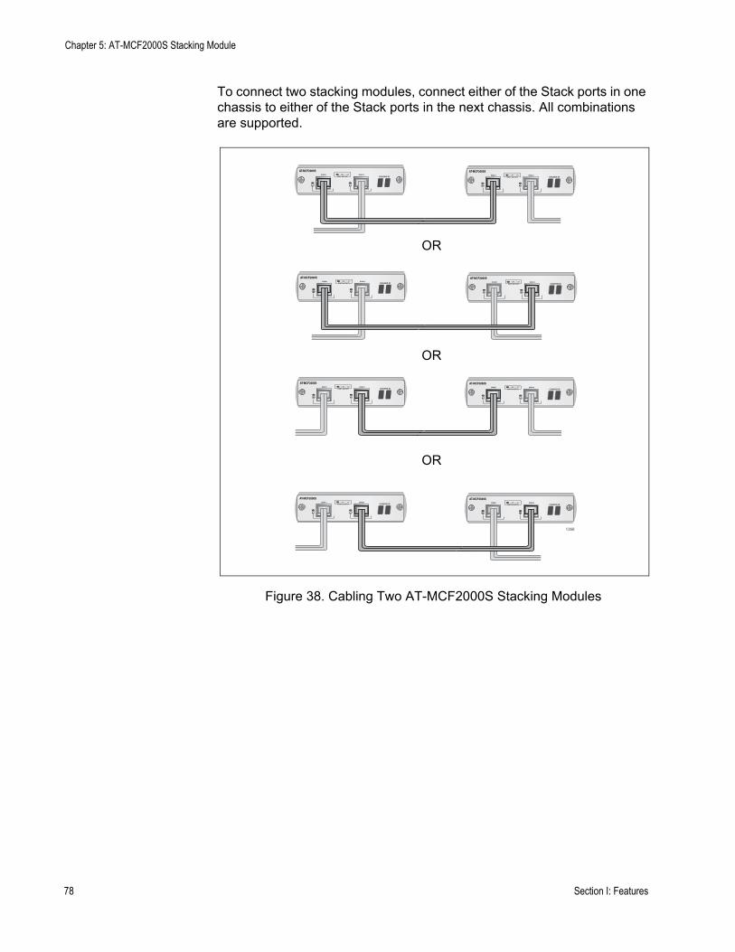
Chapter 5: AT-MCF2000S Stacking Module
To connect two stacking modules, connect either of the Stack ports in one chassis to either of the Stack ports in the next chassis. All combinations are supported.
Figure 38. Cabling Two AT-MCF2000S Stacking Modules
AT-MCF2000SLINK ACT
PORT ACTIVITYSTACK 1 STACK 2
CHASSIS ID
AT-MCF2000SLINK ACT
PORT ACTIVITYSTACK 1 STACK 2
CHASSIS ID
AT-MCF2000SLINK ACT
PORT ACTIVITYSTACK 1 STACK 2
CHASSIS ID
AT-MCF2000SLINK ACT
PORT ACTIVITYSTACK 1 STACK 2
AT-MCF2000SLINK ACT
PORT ACTIVITYSTACK 1 STACK 2
CHASSIS ID
AT-MCF2000SLINK ACT
PORT ACTIVITYSTACK 1 STACK 2
CHASSIS ID
AT-MCF2000SAT-MCF2000SLINK ACT
PORT ACTIVITYSTACK 1 STACK 2
CHASSIS IDLINK ACT
PORT ACTIVITYSTACK 1 STACK 2
CHASSIS ID
CHASSIS ID
1260
OR
OR
OR
78 Section I: Features
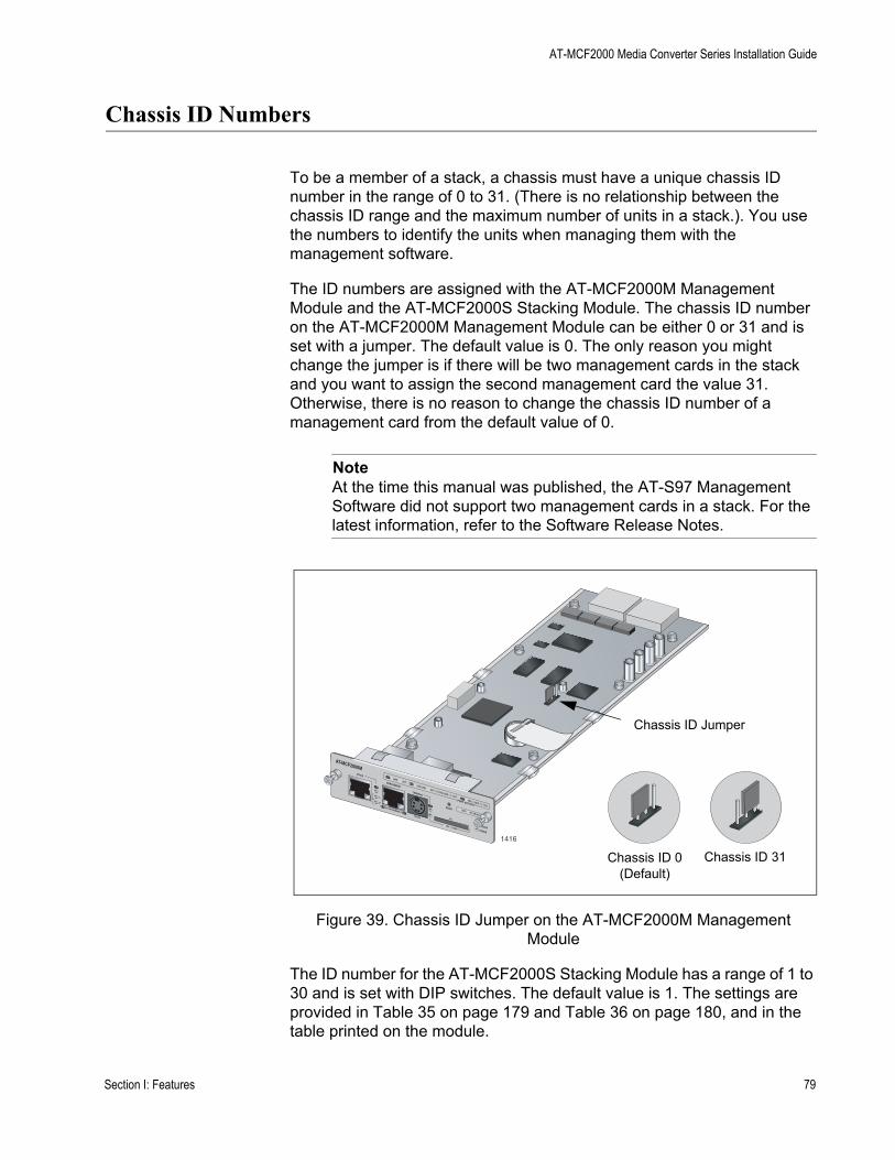
AT-MCF2000 Media Converter Series Installation Guide
Chassis ID Numbers
To be a member of a stack, a chassis must have a unique chassis ID number in the range of 0 to 31. (There is no relationship between the chassis ID range and the maximum number of units in a stack.). You use the numbers to identify the units when managing them with the management software.
The ID numbers are assigned with the AT-MCF2000M Management Module and the AT-MCF2000S Stacking Module. The chassis ID number on the AT-MCF2000M Management Module can be either 0 or 31 and is set with a jumper. The default value is 0. The only reason you might change the jumper is if there will be two management cards in the stack and you want to assign the second management card the value 31. Otherwise, there is no reason to change the chassis ID number of a management card from the default value of 0.
NoteAt the time this manual was published, the AT-S97 Management Software did not support two management cards in a stack. For the latest information, refer to the Software Release Notes.
Figure 39. Chassis ID Jumper on the AT-MCF2000M Management Module
The ID number for the AT-MCF2000S Stacking Module has a range of 1 to 30 and is set with DIP switches. The default value is 1. The settings are provided in Table 35 on page 179 and Table 36 on page 180, and in the table printed on the module.
AT-MCF2000MSTACK
MANAGEMENT
TERMINAL
10/100/1000BASE-T
RS-232
RESET
SD
RDYBUSY
MASTERPOWER
BOOTRDY
FAULT
1000 LINKACT 10/100 LINK
ACT
FDX HDXCOL
LINKACT
PORT ACTIVITY
1416
0
31
ID
Chassis ID 0 (Default)
Chassis ID 31
Chassis ID Jumper
Section I: Features 79
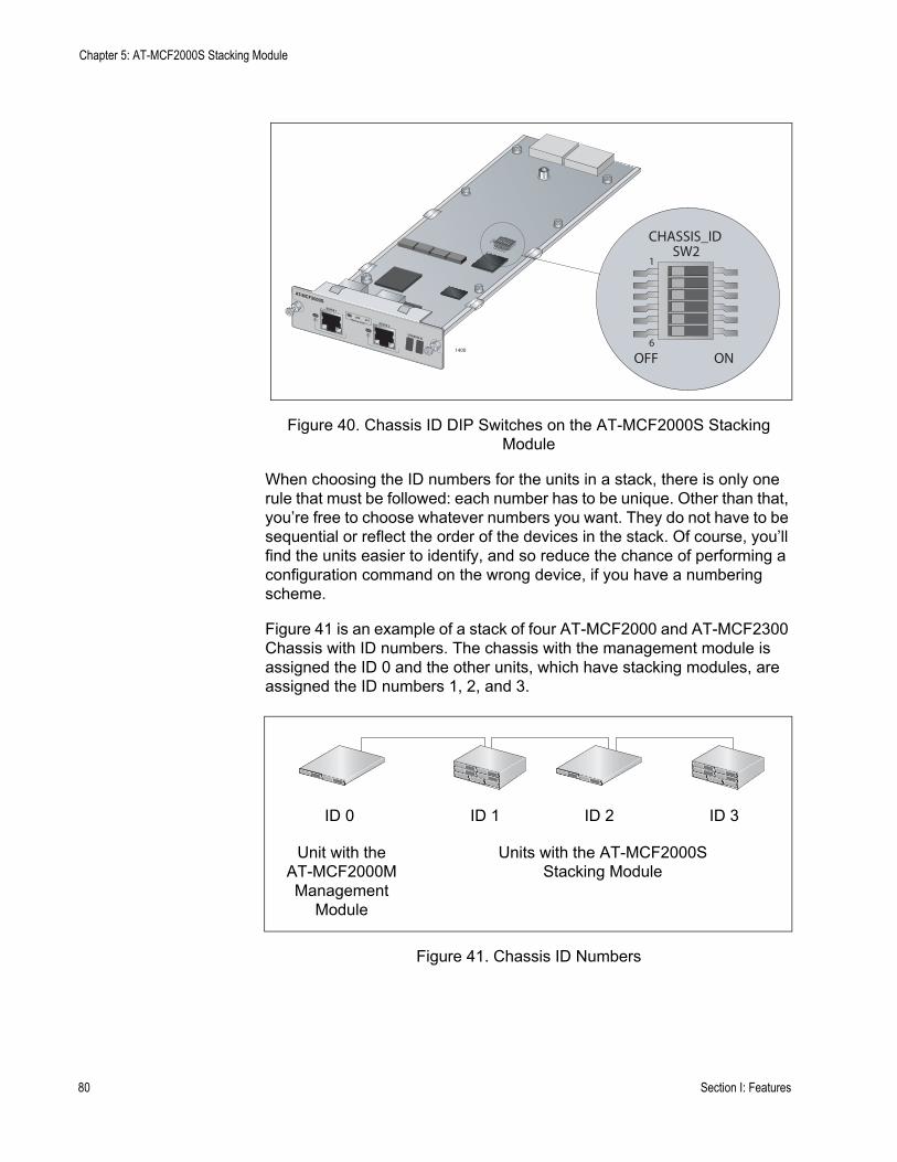
Chapter 5: AT-MCF2000S Stacking Module
Figure 40. Chassis ID DIP Switches on the AT-MCF2000S Stacking Module
When choosing the ID numbers for the units in a stack, there is only one rule that must be followed: each number has to be unique. Other than that, you’re free to choose whatever numbers you want. They do not have to be sequential or reflect the order of the devices in the stack. Of course, you’ll find the units easier to identify, and so reduce the chance of performing a configuration command on the wrong device, if you have a numbering scheme.
Figure 41 is an example of a stack of four AT-MCF2000 and AT-MCF2300 Chassis with ID numbers. The chassis with the management module is assigned the ID 0 and the other units, which have stacking modules, are assigned the ID numbers 1, 2, and 3.
Figure 41. Chassis ID Numbers
AT-MCF2000S
STACK 1
LINKACTPORT ACTIVITY STACK 2
CHASSIS ID
1400
OFF ON6
1
CHASSIS_IDSW2
Unit with theAT-MCF2000MManagement
Module
Units with the AT-MCF2000SStacking Module
ID 0 ID 1 ID 2 ID 3
80 Section I: Features

AT-MCF2000 Media Converter Series Installation Guide
LEDs
The L/A (Link/Activity) LEDs on the Stack ports are defined in this table.
Table 21. LEDs on the AT-MCF2000S Stacking Module
State Description
Off The port has not established a link with a Stack port on another stacking module.
Steady green The port has established a link with a Stack port on another stacking module.
Flashing green The Stack port is transmitting or receiving management packets.
Section I: Features 81

Chapter 5: AT-MCF2000S Stacking Module
Chassis ID LEDs
The Chassis ID LEDs display the ID number assigned to the module with the DIP switches. For information, refer to “Chassis ID Numbers” on page 79.
82 Section I: Features
AT-MCF2000 Media Converter Series Installation Guide
Guidelines to Building a Stack
Here are the guidelines to building a management stack of AT-MCF2000 and AT-MCF2300 Chassis:
❒ A stack can have up to sixteen media converter modules.❒ A stack can have both AT-MCF2000 and AT-MCF2300 Chassis.❒ The maximum distance between two Stack ports is 100 meters (328
feet).❒ The chassis containing the AT-MCF2000M Management Module has
to be at one end of the stack.❒ The other units are connected to the stack with the AT-MCF2000S
Stacking Module.❒ Each unit has to be assigned a unique chassis ID number from 0 to 31.
This number is set with a jumper on the AT-MCF2000M Management Module and with DIP switches on the AT-MCF2000S Stacking Module. The jumper and with DIP switches have to be set before the modules are installed in the units because they are not accessible afterwards.
❒ The ID numbers of the units in a stack do not have to be sequential or reflect the numerical positions of the chassis in the daisy chain topology.
❒ The stacking feature does not require an IP address configuration on the management module.
❒ A chassis that has the AT-MCF2000S Stacking Module has to be managed through the stack because the module does not have a port for local management.
❒ There cannot be any network devices, such as routers or Ethernet switches, between two Stack ports.
❒ The units in a stack function as independent media converters. The traffic of a media converter channel on a module is restricted to its channel and cannot crossover to another channel in the same chassis or another unit in the stack.
❒ Disconnecting the stacking cables does not interfere with the operations of the media converter modules because the stacking ports carry just management traffic.
❒ The chassis ID numbers of the units are not adjustable through the management software.
Section I: Features 83

Chapter 5: AT-MCF2000S Stacking Module
84 Section I: Features

Section II
Installation
This section presents the installation instructions in the following chapters:
Chapter 6, “Reviewing the Safety Precautions” on page 87Chapter 7, “Selecting a Location” on page 91Chapter 8, “Unpacking the AT-MCF2000 or AT-MCF2300 Chassis” on page 93Chapter 9, “Removing the Rubber Feet” on page 97Chapter 10, “Installing the AT-MCF2000AC or AT-MCF2300AC Power Supply Module” on page 99Chapter 11, “Installing the AT-MCF2KFAN Module” on page 103Chapter 12, “Installing a Media Converter Module” on page 107Chapter 13, “Installing the AT-MCF2000M Management Module” on page 111Chapter 14, ”Installing the AT-MCF2000S Stacking Module” on page 115Chapter 15, “Installing the Chassis in an Equipment Rack” on page 119Chapter 16, “Grounding the AT-MCF2300 Chassis” on page 123Chapter 17, “Installing the SFP Modules in the AT-MCF2032SP Module” on page 125Chapter 18, “Cabling the Ports on the Media Converter Module” on page 129Chapter 19, “Cabling the AT-MCF2000M and AT-MCF2000S Modules” on page 131Chapter 20, “Powering on the Chassis” on page 135Chapter 21, “Verifying the Installation” on page 139Chapter 22, “Starting a Local Management Session” on page 143Chapter 23, “Troubleshooting the Modules” on page 145Chapter 24, “Replacing the Modules” on page 157
Section II: Installation 85

86 Section II: Installation

Chapter 6
Reviewing the Safety Precautions
Please review the following safety precautions before you begin to install the chassis or any of the modules.
NoteThe indicates that a translation of the safety statement is available in the PDF document “Translated Safety Statements” (613-000990) posted on the Allied Telesis website at www.alliedtelesis.com. This document is also included on the documentation CD that is shipped with the product.
If you are installing the AT-MCF2032SP Media Converter Module, refer to the instructions that come with the SFP modules to determine whether they are Class 1 laser products or Class1 LED products.
Warning: Class 1 Laser product. L1 (AT-MCF2012LC/1 Module)
Warning: Do not stare into the laser beam. L2
Class 1 LED product. L3 (AT-MCF2012LC Module)
Warning: The fiber optic ports contain a Class 1 laser device. When the ports are disconnected, always cover them with the provided plug. Exposed ports may cause skin or eye damage.
L4 (AT-MCF2012LC/1 Module)
Warning: Do not look directly at the fiber optic cable ends or inspect the cable ends with an optical lens. E29
Warning: To prevent electric shock, do not remove the cover. No user-serviceable parts inside. This unit contains hazardous voltages and should only be opened by a trained and qualified technician. To avoid the possibility of electric shock, disconnect electric power to the product before connecting or disconnecting the LAN cables. E1
Section II: Installation 87
Chapter 6: Reviewing the Safety Precautions
Warning: Do not work on equipment or cables during periods of lightning activity. E2
Warning: Power cord is used as a disconnection device. To de-energize equipment, disconnect the power cord. E3
Warning: This unit might have more than one power source. To reduce the risk of electric shock, disconnect all power sources before servicing the unit. E30
Warning: Class 1 Equipment: This equipment must be earthed. The power plug must be connected to a properly wired earth ground socket outlet. An improperly wired socket outlet could place hazardous voltages on accessible metal parts. E4
Pluggable Equipment. The socket outlet shall be installed near the equipment and shall be easily accessible. E5
Caution: Air vents must not be blocked and must have free access to the room ambient air for cooling. E6
NOTE: Unused chassis slots should be kept covered with the AT-MCF2KPNL Blank Covers to prevent dust from entering the unit and to ensure proper airflow and cooling in the enclosure.
Warning: Operating Temperature. This product is designed for a maximum ambient temperature of 40° degrees C. E7
All Countries: Install product in accordance with local and National Electrical Codes. E8
Warning: Only trained and qualified personnel are allowed to install or to replace this equipment. E14
Caution: Do not install in direct sunlight, or a damp or dusty place. E16
88 Section II: Installation
AT-MCF2000 Media Converter Series Installation Guide
Caution: Risk of explosion if battery is replaced by an incorrect type. Replace only with the same or equivalent type recommended by the manufacturer. Dispose of used batteries according to the manufacturer’s instructions.
Attention: Le remplacement de la batterie par une batterie de type incorrect peut provoquer un danger d’explosion. La remplacer uniquement par une batterie du même type ou de type équivalent recommandée par le constructeur. Les batteries doivent être éliminées conformément aux instructions du constructeur. E22
Warning: Mounting of the equipment in the rack should be such that a hazardous condition is not created due to uneven mechanical loading. E25
Warning: Remove all metal jewelry, such as rings and watches, before installing or removing a line card from a powered-on chassis. E26
Warning: The chassis may be heavy and awkward to lift. Allied Telesis recommends that you get assistance when mounting the chassis in an equipment rack. E28
Caution: Installation of the equipment in a rack should be such that the amount of air flow required for safe operation of the equipment is not compromised. E36
Warning: Reliable earthing of rack-mounted equipment should be maintained. Particular attention should be given to supply connections other than direct connections to the branch circuits (e.g., use of power strips). E37
Section II: Installation 89

Chapter 6: Reviewing the Safety Precautions
90 Section II: Installation

Chapter 7
Selecting a Location
Here are the guidelines for choosing a location for the AT-MCF2000 or AT-MCF2300 Media Converter Chassis:
❒ The power outlet should be located near the unit and be easily accessible.
❒ If the chassis will have two power supplies, the power sources should be on different circuits to protect the unit from a power circuit failure.
❒ The site should provide easy access to the ports on the front of the chassis so that you can easily connect and disconnect the network cables, as well as view the unit’s LEDs.
❒ Air flow around the unit and through the side and rear vents should be unrestricted.
❒ Do not place objects on top of the chassis.❒ Do not expose the device to moisture or water. ❒ Make sure that the site is in a dust-free environment.❒ Use dedicated power circuits or power conditioners to supply reliable
electrical power to the network devices.❒ If you plan to install the chassis in an equipment rack, the rack should
be safely secured to prevent it from tipping over. Devices in a rack should be installed starting at the bottom and with the heavier devices near the bottom of the rack.
❒ If you are installing the chassis on a table, be sure the table is level and secure.
❒ Keep the media converter chassis and twisted pair cabling away from sources of electrical noise, such as radios, electric motors, transmitters, broadband amplifiers, power lines, and fluorescent fixtures.
Section II: Installation 91

Chapter 7: Selecting a Location
92 Section II: Installation
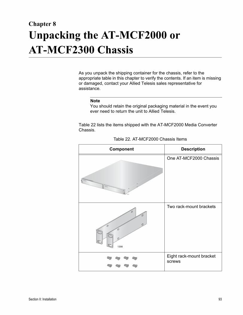
Chapter 8
Unpacking the AT-MCF2000 or AT-MCF2300 Chassis
As you unpack the shipping container for the chassis, refer to the appropriate table in this chapter to verify the contents. If an item is missing or damaged, contact your Allied Telesis sales representative for assistance.
NoteYou should retain the original packaging material in the event you ever need to return the unit to Allied Telesis.
Table 22 lists the items shipped with the AT-MCF2000 Media Converter Chassis.
Table 22. AT-MCF2000 Chassis Items
Component Description
One AT-MCF2000 Chassis
Two rack-mount brackets
Eight rack-mount bracket screws
AT-MCF2000
1
2 1415
AT-MCF2KPNL1
AT-MCF2KPNL1
AT-
MC
F200
0
1398
Section II: Installation 93
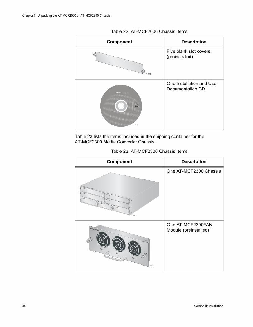
Chapter 8: Unpacking the AT-MCF2000 or AT-MCF2300 Chassis
Table 23 lists the items included in the shipping container for the AT-MCF2300 Media Converter Chassis.
Five blank slot covers (preinstalled)
One Installation and User Documentation CD
Table 23. AT-MCF2300 Chassis Items
Component Description
One AT-MCF2300 Chassis
One AT-MCF2300FAN Module (preinstalled)
Table 22. AT-MCF2000 Chassis Items
Component Description
1404
1405
AT-MCF2000
1388
AT-M
CF2
00
3
4
AT-MCF2KPNL1
AT-MCF2KPNL1
AT-MCF2KPNL2
AT-MCF2KPNL3
MANAGEMENT
A
B
1
2
AT-MCF2KPNL1
AT-MCF2KPNL1
AT-MCF2KPNL2
AT-MCF2000FAN
FAN 1
FAN 2
FAN 3
1393
94 Section II: Installation

AT-MCF2000 Media Converter Series Installation Guide
Two rack-mount brackets
Eight rack-mount bracket screws
One fan cover (preinstalled)
Seven blank slot covers (preinstalled)
One grounding lug
One Installation and User Documentation CD
Table 23. AT-MCF2300 Chassis Items
Component Description
1406
1407
1404
1409
1405
Section II: Installation 95

Chapter 8: Unpacking the AT-MCF2000 or AT-MCF2300 Chassis
96 Section II: Installation

Chapter 9
Removing the Rubber Feet
This procedure is optional. It is used to remove the rubber feet from the bottom of the chassis. It should only be performed if you’ll be installing the chassis in an equipment rack. By removing the rubber feet, it may be possible to install the enclosure closer to the device below it, thus allowing you to install more devices in the rack. To remove the rubber feet:
1. Place the unit upside down on a level, secure surface.
2. Using a flat-head screwdriver, remove the snap-on plastic feet from the bottom of the chassis, as shown in Figure 42.
Figure 42. Removing the Chassis Feet
3. Return the chassis to the upright position.
4. Go to the next procedure for instructions on how to install a power module.
Section II: Installation 97

Chapter 9: Removing the Rubber Feet
98 Section II: Installation

Chapter 10
Installing the AT-MCF2000AC or AT-MCF2300AC Power Supply Module
NoteThe AT-MCF2000AC and AT-MCF2300AC Modules are the power supply units for the AT-MCF2000 Chassis and the AT-MCF2300 Chassis, respectively. Before installing a power supply module, check to be sure you have the correct module for the chassis.
CautionTo maintain adequate airflow and cooling, the AT-MCF2000 Chassis must have two AT-MCF2000AC Power Supply Modules or one AT-MCF2000AC Module and one AT-MCF2KFAN Module.
This procedure uses the AT-MCF2000 Chassis for illustration purposes. For the locations of the power supply slots on the AT-MCF2300 Chassis, refer to Figure 3 on page 29.
To install the AT-MCF2000AC or AT-MCF2300AC Power Supply Module:
1. Remove the AT-MCF2KPNL2 blank panel from one of the power supply slots on the chassis by loosening the two captive screws on the panel with a cross-head screwdriver. You can install the power supply module in either of the power supply slots.
Figure 43. Removing the Blank Panel from a Power Supply Slot
AT-MCF2KPNL2 AT-MCF2KPNL3
1111-a
MA
A
Section II: Installation 99
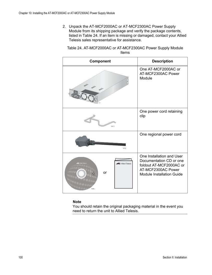
Chapter 10: Installing the AT-MCF2000AC or AT-MCF2300AC Power Supply Module
2. Unpack the AT-MCF2000AC or AT-MCF2300AC Power Supply Module from its shipping package and verify the package contents, listed in Table 24. If an item is missing or damaged, contact your Allied Telesis sales representative for assistance.
NoteYou should retain the original packaging material in the event you need to return the unit to Allied Telesis.
Table 24. AT-MCF2000AC or AT-MCF2300AC Power Supply Module Items
Component Description
One AT-MCF2000AC or AT-MCF2300AC Power Module
One power cord retaining clip
One regional power cord
One Installation and User Documentation CD or one foldout AT-MCF2000AC or AT-MCF2300AC Power Module Installation Guide
1110
1411
1412
1405
or
100 Section II: Installation
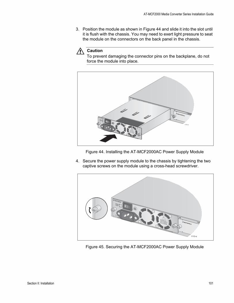
AT-MCF2000 Media Converter Series Installation Guide
3. Position the module as shown in Figure 44 and slide it into the slot until it is flush with the chassis. You may need to exert light pressure to seat the module on the connectors on the back panel in the chassis.
CautionTo prevent damaging the connector pins on the backplane, do not force the module into place.
Figure 44. Installing the AT-MCF2000AC Power Supply Module
4. Secure the power supply module to the chassis by tightening the two captive screws on the module using a cross-head screwdriver.
Figure 45. Securing the AT-MCF2000AC Power Supply Module
AT-MCF2KPNL3
NORMALFAULT
STATUS PSU
FAN
1111-a
MANAG
A
1113-a
AT-MCF2KPNL3
NORMALFAULT
STATUS PSU
FAN
M
A
Section II: Installation 101
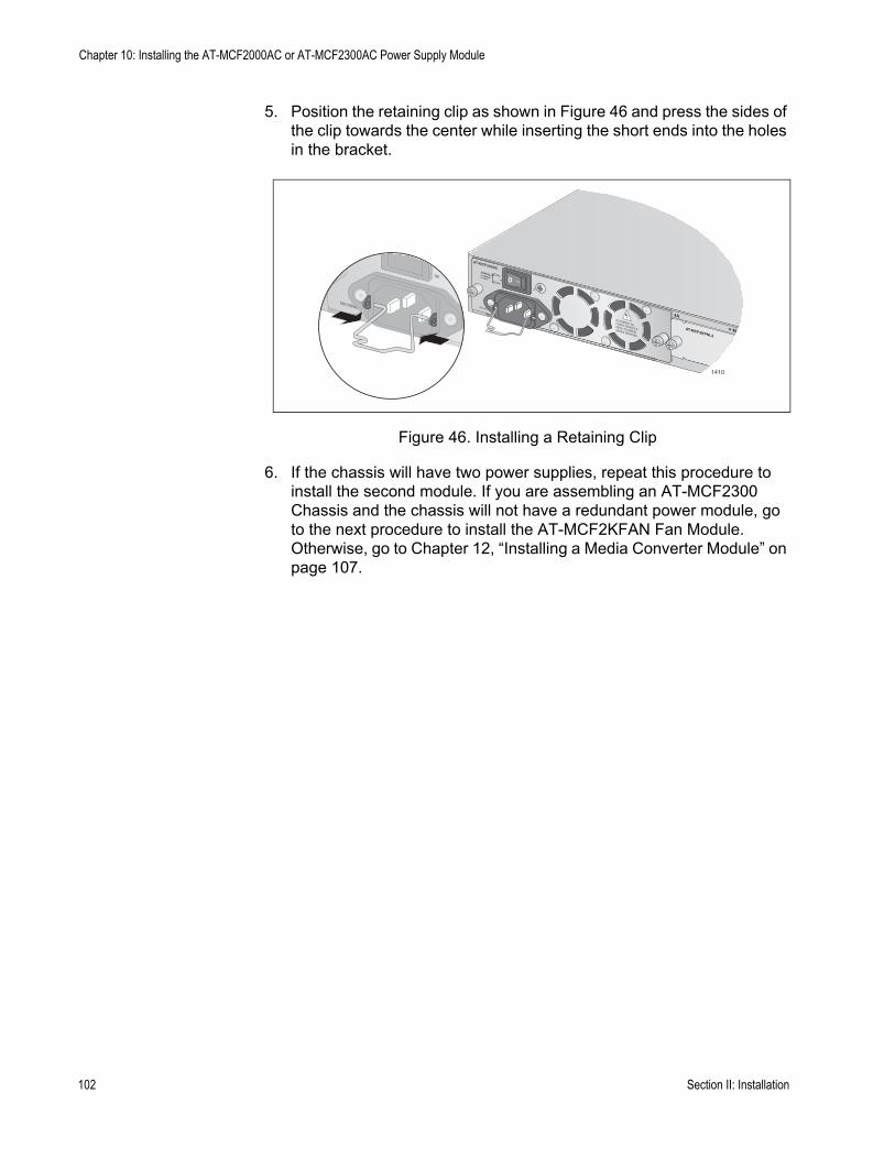
Chapter 10: Installing the AT-MCF2000AC or AT-MCF2300AC Power Supply Module
5. Position the retaining clip as shown in Figure 46 and press the sides of the clip towards the center while inserting the short ends into the holes in the bracket.
Figure 46. Installing a Retaining Clip
6. If the chassis will have two power supplies, repeat this procedure to install the second module. If you are assembling an AT-MCF2300 Chassis and the chassis will not have a redundant power module, go to the next procedure to install the AT-MCF2KFAN Fan Module. Otherwise, go to Chapter 12, “Installing a Media Converter Module” on page 107.
1410
AT-MCF2KPNL3
NORMALFAULT
STATUS PSU
FAN
M
A
102 Section II: Installation
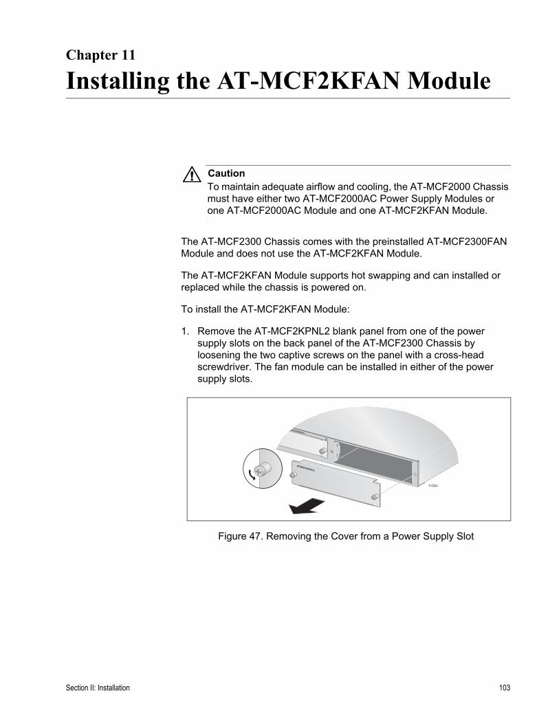
Chapter 11
Installing the AT-MCF2KFAN Module
CautionTo maintain adequate airflow and cooling, the AT-MCF2000 Chassis must have either two AT-MCF2000AC Power Supply Modules or one AT-MCF2000AC Module and one AT-MCF2KFAN Module.
The AT-MCF2300 Chassis comes with the preinstalled AT-MCF2300FAN Module and does not use the AT-MCF2KFAN Module.
The AT-MCF2KFAN Module supports hot swapping and can installed or replaced while the chassis is powered on.
To install the AT-MCF2KFAN Module:
1. Remove the AT-MCF2KPNL2 blank panel from one of the power supply slots on the back panel of the AT-MCF2300 Chassis by loosening the two captive screws on the panel with a cross-head screwdriver. The fan module can be installed in either of the power supply slots.
Figure 47. Removing the Cover from a Power Supply Slot
1125c
MANAGEMENT
B
AT-MCF2KPNL2
Section II: Installation 103
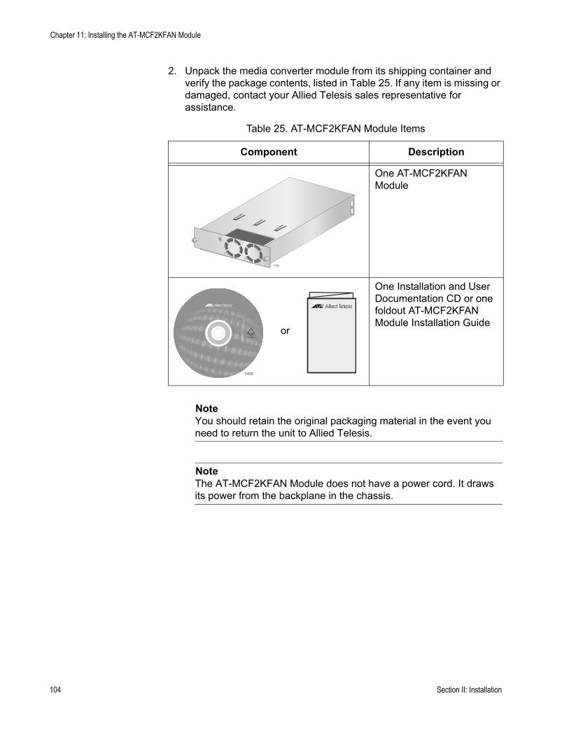
Chapter 11: Installing the AT-MCF2KFAN Module
2. Unpack the media converter module from its shipping container and verify the package contents, listed in Table 25. If any item is missing or damaged, contact your Allied Telesis sales representative for assistance.
NoteYou should retain the original packaging material in the event you need to return the unit to Allied Telesis.
NoteThe AT-MCF2KFAN Module does not have a power cord. It draws its power from the backplane in the chassis.
Table 25. AT-MCF2KFAN Module Items
Component Description
One AT-MCF2KFAN Module
One Installation and User Documentation CD or one foldout AT-MCF2KFAN Module Installation Guide
1123
1405
or
104 Section II: Installation
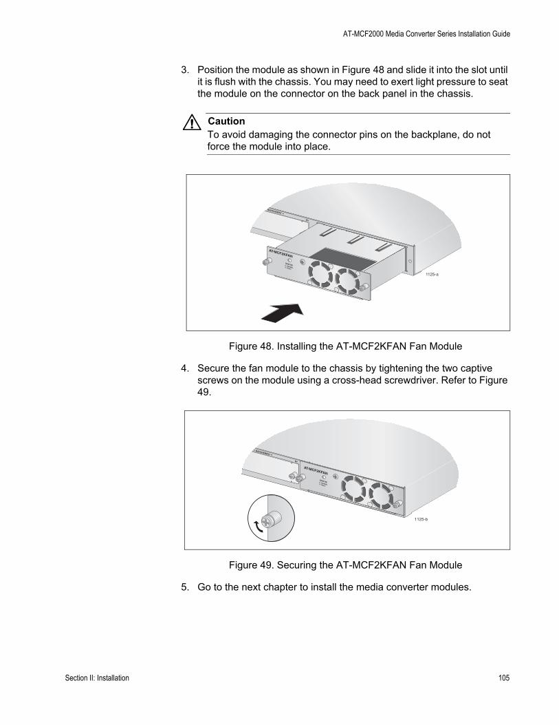
AT-MCF2000 Media Converter Series Installation Guide
3. Position the module as shown in Figure 48 and slide it into the slot until it is flush with the chassis. You may need to exert light pressure to seat the module on the connector on the back panel in the chassis.
CautionTo avoid damaging the connector pins on the backplane, do not force the module into place.
Figure 48. Installing the AT-MCF2KFAN Fan Module
4. Secure the fan module to the chassis by tightening the two captive screws on the module using a cross-head screwdriver. Refer to Figure 49.
Figure 49. Securing the AT-MCF2KFAN Fan Module
5. Go to the next chapter to install the media converter modules.
1125-a
MANAGEMENT
B
AT-MCF2KFAN
NORMALFAULT
STATUS
1125-b
AT-MCF2KFAN
NORMALFAULT
STATUS
MANAGEMENT
B
Section II: Installation 105

Chapter 11: Installing the AT-MCF2KFAN Module
106 Section II: Installation

Chapter 12
Installing a Media Converter Module
NoteThe media converter modules support hot swapping. The chassis can be powered on when you install a media converter module.
NoteThere are no adjustable switches on the circuit boards of the media converter modules.
CautionA media converter module is sensitive to and can be damaged by electrostatic discharge. Wear a grounding device and observe electrostatic discharge precautions when installing the module in the chassis.
This procedure uses the AT-MCF2000 Chassis for illustration purposes. For the locations of the slots for the media converter modules in the AT-MCF2300 Chassis, refer to Figure 3 on page 29.
To install the AT-MCF2012LC, AT-MCF2012LC/1 or AT-MCF2032SP Media Converter Module:
1. Using a cross-head screwdriver, remove the AT-MCF2KPNL1 blank panel from a media converter slot on the front panel of the chassis.
Figure 50. Removing a Blank Cover from a Media Converter Slot
AT-MCF2000
1
1120-a
Section II: Installation 107
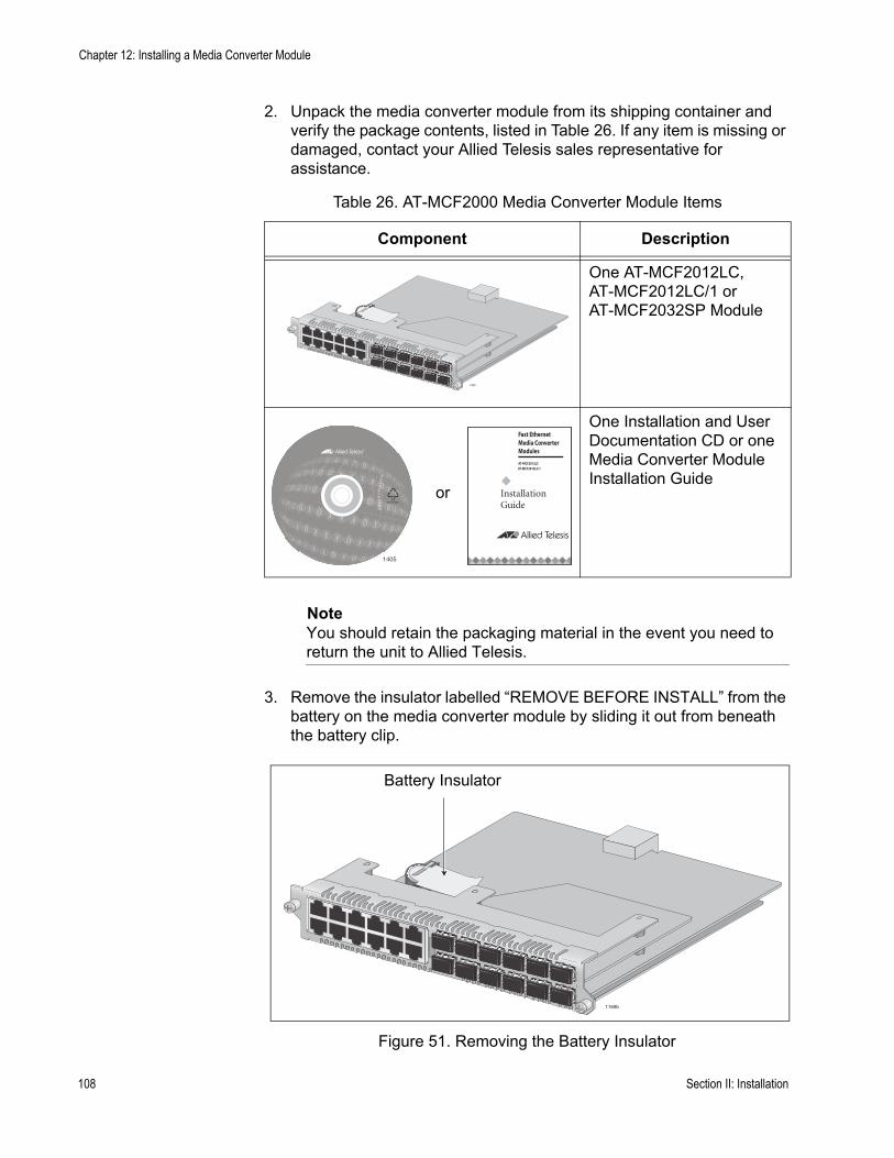
Chapter 12: Installing a Media Converter Module
2. Unpack the media converter module from its shipping container and verify the package contents, listed in Table 26. If any item is missing or damaged, contact your Allied Telesis sales representative for assistance.
NoteYou should retain the packaging material in the event you need to return the unit to Allied Telesis.
3. Remove the insulator labelled “REMOVE BEFORE INSTALL” from the battery on the media converter module by sliding it out from beneath the battery clip.
Figure 51. Removing the Battery Insulator
Table 26. AT-MCF2000 Media Converter Module Items
Component Description
One AT-MCF2012LC, AT-MCF2012LC/1 or AT-MCF2032SP Module
One Installation and User Documentation CD or one Media Converter Module Installation Guide
1390
1405
Fast EthernetMedia Converter
AT-MCF2012LC
InstallationGuide
Modules
AT-MCF2012LC/1
or
1169b
Battery Insulator
108 Section II: Installation

AT-MCF2000 Media Converter Series Installation Guide
4. Align the edges of the module with the guides in the slot and carefully slide the module into the chassis until it is flush with the front of the chassis. Light pressure may be needed to seat the module on the connector on the backplane in the chassis.
CautionDo not force the module into place. If there is resistance, remove the module, verify that the edges of the card are properly aligned in the guides in the chassis’ module slot, and reinsert it.
Figure 52. Installing a Media Converter Module
5. Tighten the two captive screws on the media converter module with a cross-head screwdriver to secure the module to the chassis.
Figure 53. Securing a Media Converter Module
6. Repeat this procedure to install additional media converter modules.
1121-a
1
AT-
MC
F20
12L
C
AT-MCF2000
1122-a
1
AT-
MC
F20
12L
C
Section II: Installation 109

Chapter 12: Installing a Media Converter Module
110 Section II: Installation

Chapter 13
Installing the AT-MCF2000M Management Module
NoteBecause the AT-MCF2000M Management Module supports hot-swapping, you can install it while the chassis is powered on.
CautionThe module is sensitive to and can be damaged by electrostatic discharge. Wear a grounding device and observe electrostatic discharge precautions when installing the module in the chassis.
This procedure uses the AT-MCF2000 Chassis for illustration purposes. For the location of the Management slot on the AT-MCF2300 Chassis, refer to Figure 3 on page 29.
To install the optional AT-MCF2000M Management Module:
1. Using a cross-head screwdriver, loosen the two captive screws that secure the blank panel over the Management slot and remove the panel from the chassis.
Figure 54. Removing the Blank Panel from the Management Slot
AT-MCF2KFAN
NORMAFAULT
STATUS
AT-MCF2KPNL3
Section II: Installation 111
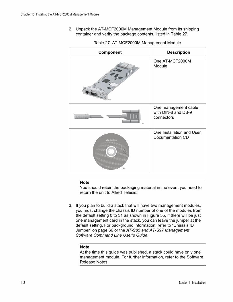
Chapter 13: Installing the AT-MCF2000M Management Module
2. Unpack the AT-MCF2000M Management Module from its shipping container and verify the package contents, listed in Table 27.
NoteYou should retain the packaging material in the event you need to return the unit to Allied Telesis.
3. If you plan to build a stack that will have two management modules, you must change the chassis ID number of one of the modules from the default setting 0 to 31 as shown in Figure 55. If there will be just one management card in the stack, you can leave the jumper at the default setting. For background information, refer to “Chassis ID Jumper” on page 66 or the AT-S85 and AT-S97 Management Software Command Line User’s Guide.
NoteAt the time this guide was published, a stack could have only one management module. For further information, refer to the Software Release Notes.
Table 27. AT-MCF2000M Management Module
Component Description
One AT-MCF2000M Module
One management cable with DIN-8 and DB-9 connectors
One Installation and User Documentation CD
AT-MCF2000MSTACK
MANAGEMENT
TERMINAL
10/100/1000BASE-T
RS-232
RESET
SD
RDYBUSY
MASTERPOWER
BOOTRDY
FAULT
1000 LINKACT 10/100 LINK
ACT
FDX HDXCOL
LINKACT
PORT ACTIVITY
1423
0
31
ID
1417
1405
112 Section II: Installation
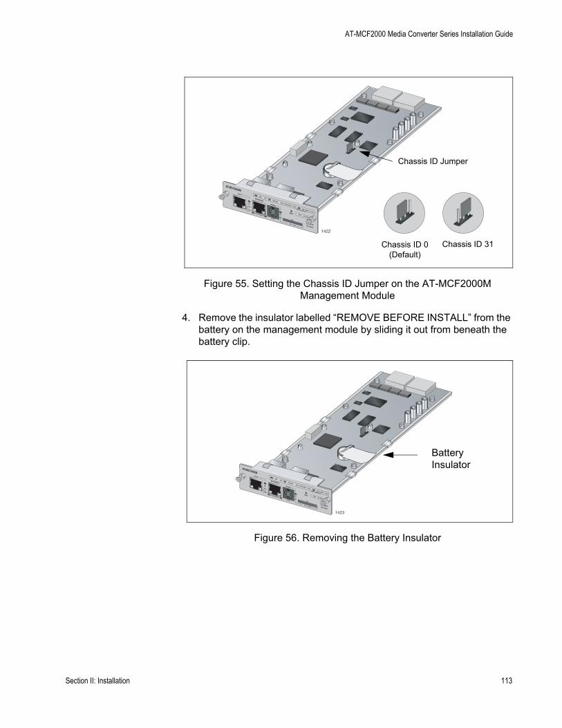
AT-MCF2000 Media Converter Series Installation Guide
Figure 55. Setting the Chassis ID Jumper on the AT-MCF2000M Management Module
4. Remove the insulator labelled “REMOVE BEFORE INSTALL” from the battery on the management module by sliding it out from beneath the battery clip.
Figure 56. Removing the Battery Insulator
AT-MCF2000MSTACK
MANAGEMENT
TERMINAL
10/100/1000BASE-T
RS-232
RESET
SD
RDYBUSY
MASTERPOWER
BOOTRDY
FAULT
1000 LINKACT 10/100 LINK
ACT
FDX HDXCOL
LINKACT
PORT ACTIVITY
1422
0
31
ID
Chassis ID 0 (Default)
Chassis ID 31
Chassis ID Jumper
AT-MCF2000MSTACK
MANAGEMENT
TERMINAL
10/100/1000BASE-T
RS-232
RESET
SD
RDYBUSY
MASTERPOWER
BOOTRDY
FAULT
1000 LINKACT 10/100 LINK
ACT
FDX HDXCOL
LINKACT
PORT ACTIVITY
1423
0
31
ID
Battery Insulator
Section II: Installation 113
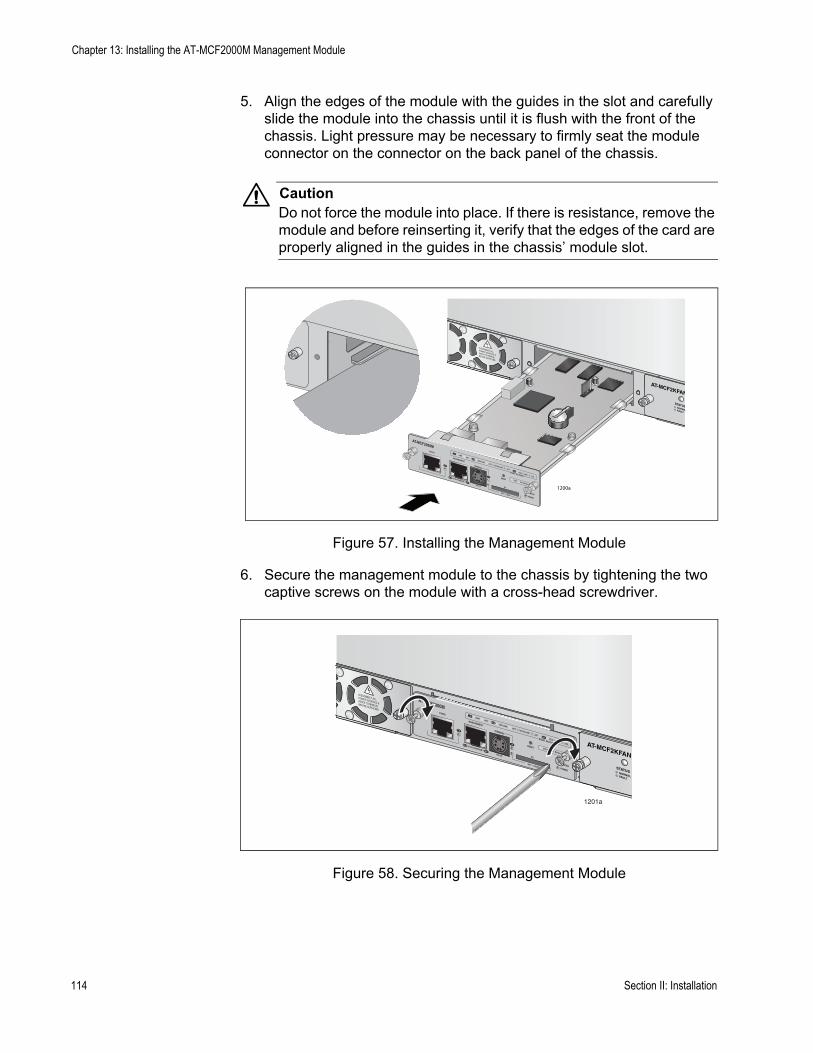
Chapter 13: Installing the AT-MCF2000M Management Module
5. Align the edges of the module with the guides in the slot and carefully slide the module into the chassis until it is flush with the front of the chassis. Light pressure may be necessary to firmly seat the module connector on the connector on the back panel of the chassis.
CautionDo not force the module into place. If there is resistance, remove the module and before reinserting it, verify that the edges of the card are properly aligned in the guides in the chassis’ module slot.
Figure 57. Installing the Management Module
6. Secure the management module to the chassis by tightening the two captive screws on the module with a cross-head screwdriver.
Figure 58. Securing the Management Module
AT-MCF2KFAN
NORMALFAULT
STATUS
AT-MCF2000MSTACK
MANAGEMENT
TERMINAL
10/100/1000BASE-T
RS-232
RESET
SD
RDYBUSY
MASTERPOWER
BOOTRDY
FAULT
1000 LINKACT 10/100 LINK
ACT
FDX HDXCOL
LINKACT
PORT ACTIVITY
1200a
1201a
AT-MCF2000MSTACK
MANAGEMENT
TERMINAL
10/100/1000BASE-T
RS-232
RESET
SD
RDYBUSY
MASTERPOWER
BOOTRDY
FAULT
1000 LINKACT 10/100 LINK
ACT
FDX HDXCOL
LINKACT
PORT ACTIVITY AT-MCF2KFAN
NORMALFAULT
STATUS
114 Section II: Installation
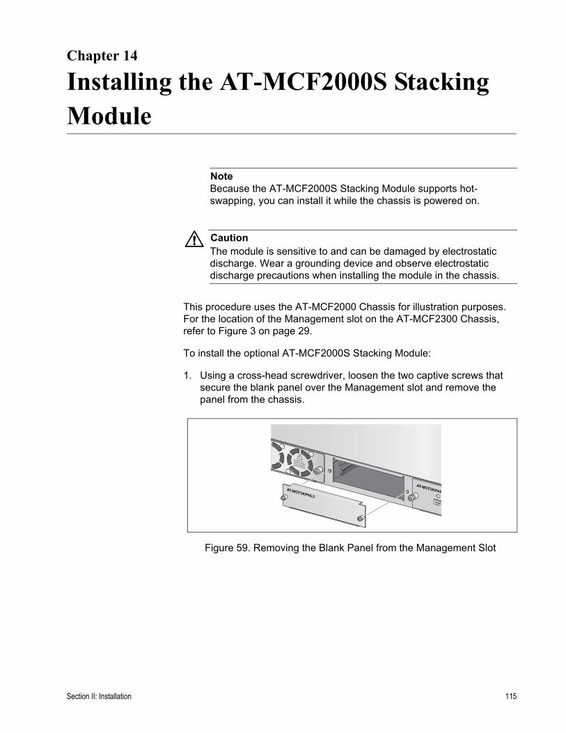
Chapter 14
Installing the AT-MCF2000S Stacking Module
NoteBecause the AT-MCF2000S Stacking Module supports hot-swapping, you can install it while the chassis is powered on.
CautionThe module is sensitive to and can be damaged by electrostatic discharge. Wear a grounding device and observe electrostatic discharge precautions when installing the module in the chassis.
This procedure uses the AT-MCF2000 Chassis for illustration purposes. For the location of the Management slot on the AT-MCF2300 Chassis, refer to Figure 3 on page 29.
To install the optional AT-MCF2000S Stacking Module:
1. Using a cross-head screwdriver, loosen the two captive screws that secure the blank panel over the Management slot and remove the panel from the chassis.
Figure 59. Removing the Blank Panel from the Management Slot
AT-MCF2KFAN
NORMAFAULT
STATUS
AT-MCF2KPNL3
Section II: Installation 115
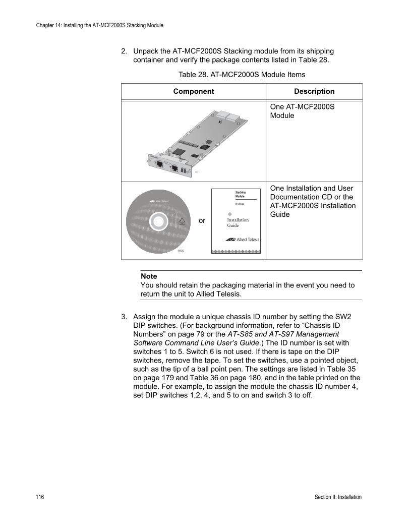
Chapter 14: Installing the AT-MCF2000S Stacking Module
2. Unpack the AT-MCF2000S Stacking module from its shipping container and verify the package contents listed in Table 28.
NoteYou should retain the packaging material in the event you need to return the unit to Allied Telesis.
3. Assign the module a unique chassis ID number by setting the SW2 DIP switches. (For background information, refer to “Chassis ID Numbers” on page 79 or the AT-S85 and AT-S97 Management Software Command Line User’s Guide.) The ID number is set with switches 1 to 5. Switch 6 is not used. If there is tape on the DIP switches, remove the tape. To set the switches, use a pointed object, such as the tip of a ball point pen. The settings are listed in Table 35 on page 179 and Table 36 on page 180, and in the table printed on the module. For example, to assign the module the chassis ID number 4, set DIP switches 1,2, 4, and 5 to on and switch 3 to off.
Table 28. AT-MCF2000S Module Items
Component Description
One AT-MCF2000S Module
One Installation and User Documentation CD or the AT-MCF2000S Installation Guide
AT-MCF2000S
STACK 1
LINKACTPORT ACTIVITY STACK 2
CHASSIS ID
1264
1405
Stacking Module
AT-MCF2000S
InstallationGuide
or
116 Section II: Installation
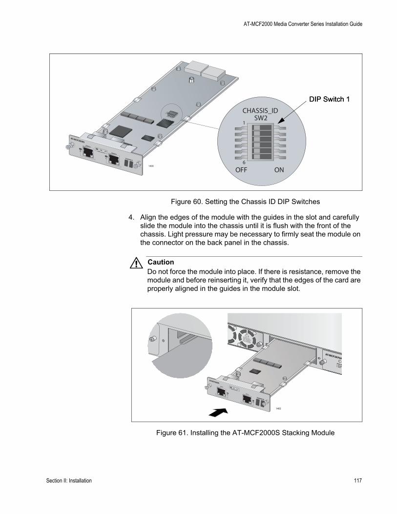
AT-MCF2000 Media Converter Series Installation Guide
Figure 60. Setting the Chassis ID DIP Switches
4. Align the edges of the module with the guides in the slot and carefully slide the module into the chassis until it is flush with the front of the chassis. Light pressure may be necessary to firmly seat the module on the connector on the back panel in the chassis.
CautionDo not force the module into place. If there is resistance, remove the module and before reinserting it, verify that the edges of the card are properly aligned in the guides in the module slot.
Figure 61. Installing the AT-MCF2000S Stacking Module
AT-MCF2000S
STACK 1
LINKACTPORT ACTIVITY STACK 2
CHASSIS ID
1400
OFF ON6
1
CHASSIS_IDSW2
DIP Switch 1DIP Switch 1
AT-MCF2KFAN
NORMALFAULT
STATUS
1402
AT-MCF2000S
STACK 1
PO
LINKACTPORT ACTIVITY
CHASSIS ID
STACK 2
Section II: Installation 117
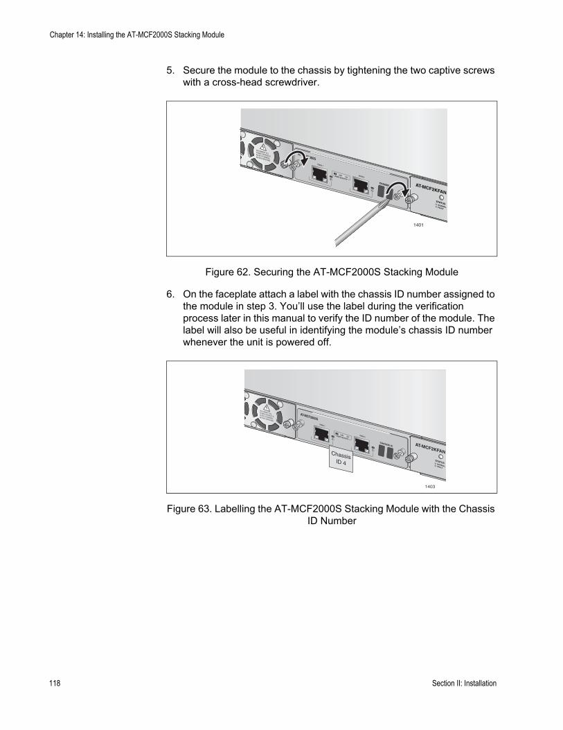
Chapter 14: Installing the AT-MCF2000S Stacking Module
5. Secure the module to the chassis by tightening the two captive screws with a cross-head screwdriver.
Figure 62. Securing the AT-MCF2000S Stacking Module
6. On the faceplate attach a label with the chassis ID number assigned to the module in step 3. You’ll use the label during the verification process later in this manual to verify the ID number of the module. The label will also be useful in identifying the module’s chassis ID number whenever the unit is powered off.
Figure 63. Labelling the AT-MCF2000S Stacking Module with the Chassis ID Number
1401
AT-MCF2000S
WER
LINKACT
PORT ACTIVITY
STACK 1
CHASSIS ID AT-MCF2KFAN
NORMALFAULT
STATUS
STACK 2
1403
AT-MCF2000S
WER
LINKACT
PORT ACTIVITY
STACK 1
CHASSIS ID AT-MCF2KFAN
NORMALFAULT
STATUS
STACK 2
ChassisID 4
118 Section II: Installation

Chapter 15
Installing the Chassis in an Equipment Rack
To install the chassis in a standard 19-inch equipment rack:
1. Attach a rack-mount bracket to one side of the chassis using four of the screws included with the unit.
Figure 64. Attaching a Rack-mount Bracket to the AT-MCF2000 Chassis
Figure 65. Attaching a Rack-mount Bracket to the AT-MCF2300 Chassis
1109-a
2
AT-
MC
F200
0
1424
AT-
MC
F200
4
2
T-MCF2KPNL2
Section II: Installation 119

Chapter 15: Installing the Chassis in an Equipment Rack
The brackets for the AT-MCF2300 Chassis are designed so that you install the unit flush with the front of the equipment rack or recessed one or two inches. You can also install the unit so that it extends two inches from the front of the rack. The various bracket positions are illustrated in Figure 66; the { } symbols identify the appropriate screw holes for the different installations.
Figure 66. Rack-mount Bracket Positions on the AT-MCF2300 Chassis
1419
Flush with thefront of the rack
Recess 1 inch
Recess 2 inches
Front of rack
Extend 2 inches
120 Section II: Installation
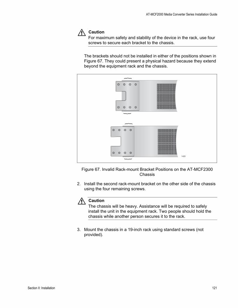
AT-MCF2000 Media Converter Series Installation Guide
CautionFor maximum safety and stability of the device in the rack, use four screws to secure each bracket to the chassis.
The brackets should not be installed in either of the positions shown in Figure 67. They could present a physical hazard because they extend beyond the equipment rack and the chassis.
Figure 67. Invalid Rack-mount Bracket Positions on the AT-MCF2300 Chassis
2. Install the second rack-mount bracket on the other side of the chassis using the four remaining screws.
CautionThe chassis will be heavy. Assistance will be required to safely install the unit in the equipment rack. Two people should hold the chassis while another person secures it to the rack.
3. Mount the chassis in a 19-inch rack using standard screws (not provided).
1420
Section II: Installation 121

Chapter 15: Installing the Chassis in an Equipment Rack
122 Section II: Installation

Chapter 16
Grounding the AT-MCF2300 Chassis
If you installed the AT-MCF2300 Chassis in an equipment rack, perform this procedure to ground the unit. This procedure requires these items:
Phillips head No. 2 screwdriver10 AWG solid wire (The length of the wire will depend on your installation.)Crimping toolGrounding lug (included with the chassis)
To ground the AT-MCF2300 Chassis:
1. Strip the grounding wire as shown in Figure 68.
Figure 68. Stripping the Grounding Wire
2. Use a crimping tool to attach the wire to the grounding lug included with the chassis.
Figure 69. Attaching the Grounding Wire to the Grounding Lug
3. Remove the two grounding lug screws from the lower left corner on the back panel of the chassis.
11mm ±1mm(0.44in. ±0.03in.)
100
102
Section II: Installation 123
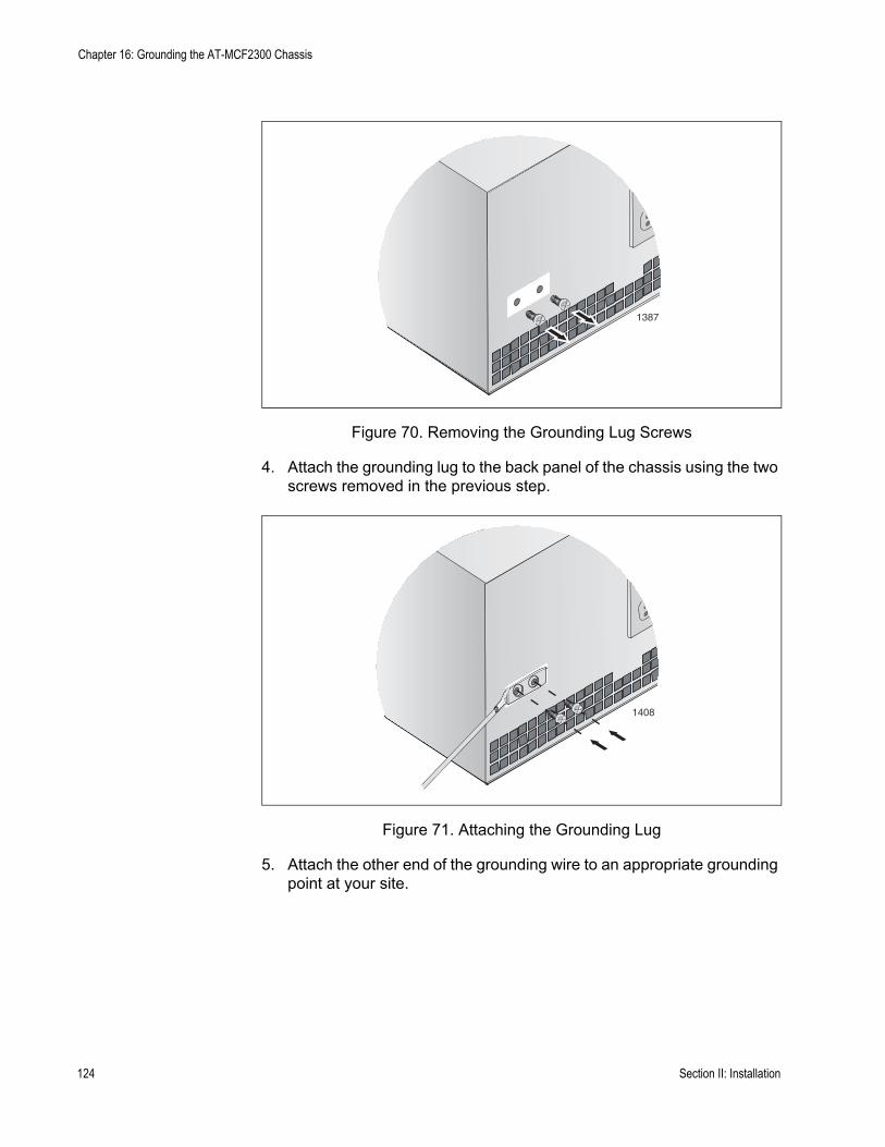
Chapter 16: Grounding the AT-MCF2300 Chassis
Figure 70. Removing the Grounding Lug Screws
4. Attach the grounding lug to the back panel of the chassis using the two screws removed in the previous step.
Figure 71. Attaching the Grounding Lug
5. Attach the other end of the grounding wire to an appropriate grounding point at your site.
STATUS
NOR
FAUL
AT-MC
1387
1408
STATUS
NOR
FAUL
AT-MC
124 Section II: Installation
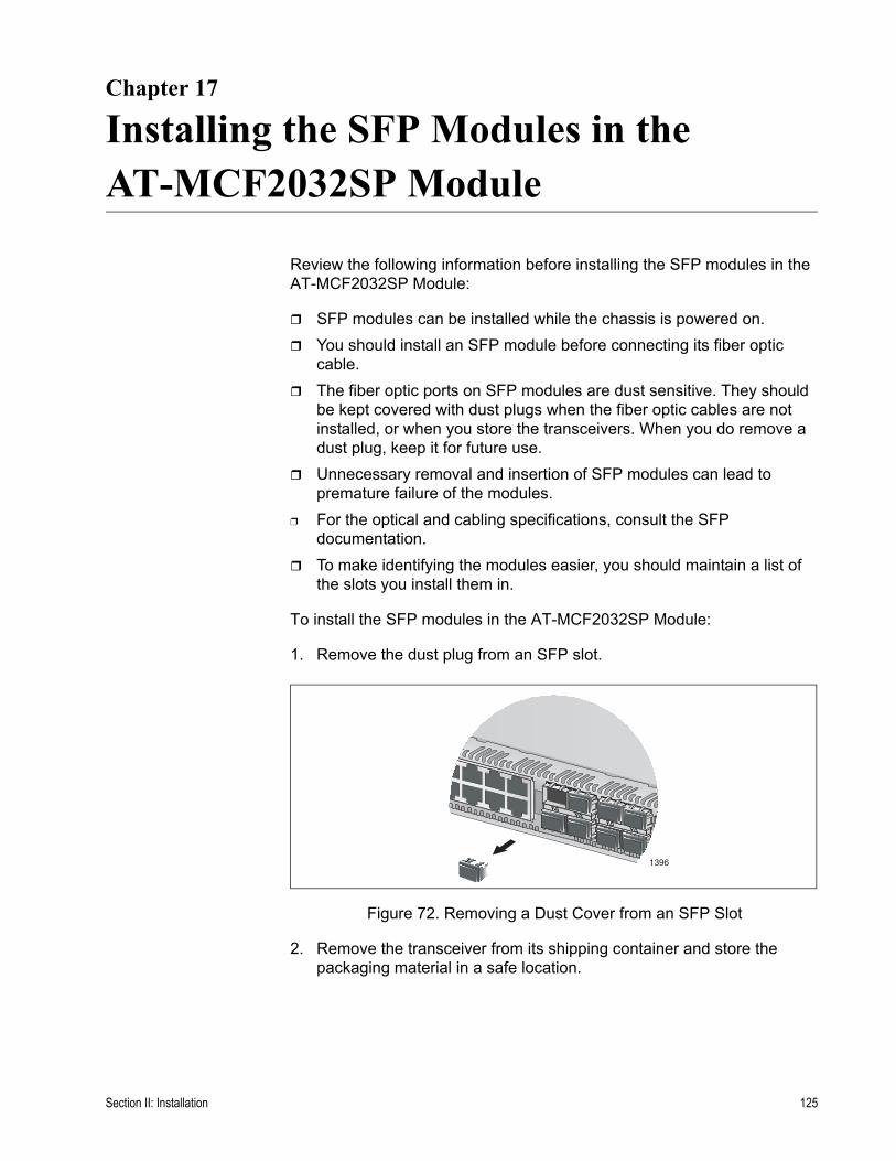
Chapter 17
Installing the SFP Modules in the AT-MCF2032SP Module
Review the following information before installing the SFP modules in the AT-MCF2032SP Module:
SFP modules can be installed while the chassis is powered on.You should install an SFP module before connecting its fiber optic cable.The fiber optic ports on SFP modules are dust sensitive. They should be kept covered with dust plugs when the fiber optic cables are not installed, or when you store the transceivers. When you do remove a dust plug, keep it for future use.Unnecessary removal and insertion of SFP modules can lead to premature failure of the modules.
❒ For the optical and cabling specifications, consult the SFP documentation.To make identifying the modules easier, you should maintain a list of the slots you install them in.
To install the SFP modules in the AT-MCF2032SP Module:
1. Remove the dust plug from an SFP slot.
Figure 72. Removing a Dust Cover from an SFP Slot
2. Remove the transceiver from its shipping container and store the packaging material in a safe location.
1396
Section II: Installation 125
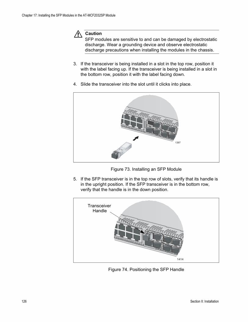
Chapter 17: Installing the SFP Modules in the AT-MCF2032SP Module
CautionSFP modules are sensitive to and can be damaged by electrostatic discharge. Wear a grounding device and observe electrostatic discharge precautions when installing the modules in the chassis.
3. If the transceiver is being installed in a slot in the top row, position it with the label facing up. If the transceiver is being installed in a slot in the bottom row, position it with the label facing down.
4. Slide the transceiver into the slot until it clicks into place.
Figure 73. Installing an SFP Module
5. If the SFP transceiver is in the top row of slots, verify that its handle is in the upright position. If the SFP transceiver is in the bottom row, verify that the handle is in the down position.
Figure 74. Positioning the SFP Handle
1397
1414
TransceiverHandle
126 Section II: Installation

AT-MCF2000 Media Converter Series Installation Guide
NoteDo not remove the dust cap from an SFP transceiver until you are ready to connect a fiber optic cable. Dust contamination can adversely affect a fiber optic port.
6. Repeat this procedure to install the remaining SFP modules.
Section II: Installation 127

Chapter 17: Installing the SFP Modules in the AT-MCF2032SP Module
128 Section II: Installation

Chapter 18
Cabling the Ports on the Media Converter Module
You should review “Media Converter Channels” on page 34 and “Guidelines to Using the Media Converter Modules” on page 53 before you begin to connect the network cables to the ports on a media converter module.
Here are the guidelines for connecting the network cables to the twisted pair ports:
❒ The RJ-45 connector should fit snugly into the port on the module and the tab on the connector should lock the connector into place.
❒ The default setting for a twisted pair port is Auto-Negotiation and auto-MDI/MDI-X.
Here are the guidelines for connecting the fiber optic cables to the fiber optic ports:
❒ Do not remove the dust cover from a fiber optic port until you are ready to connect the cable. Dust contamination can adversely affect the operation of the port.
❒ The connector on the fiber optic cable should firmly lock into place on the port.
❒ Review the information in “Fiber Optic Ports” on page 36 to verify that you are using the correct type of fiber optic cable and are not exceeding the operating distance of the fiber optic port.
❒ Verify that the operating specifications of the module’s fiber optic port are compatible with the fiber optic port on the network device. For the fiber optic port specifications for the AT-MCF2012LC and AT-MCF2012LC/1 Modules, refer to “100Base-FX Fiber Optic Ports” on page 175.
❒ For instructions on how to clear the fiber optic ports, refer to Chapter C, “Cleaning Fiber Optic Connectors” on page 181.
Section II: Installation 129

Chapter 18: Cabling the Ports on the Media Converter Module
130 Section II: Installation

Chapter 19
Cabling the AT-MCF2000M and AT-MCF2000S Modules
To cable the ports on the AT-MCF2000M Management Module and the AT-MCF2000S Stacking Module:
1. To provide the management module with access to your network, connect a standard TIA/EIA 568-B-compliant Enhanced Category 5 (Cat 5e) shielded or unshielded cable to the 10/100/1000Base-T Management port. Connect the other end of the cable to a network device, such as a Fast Ethernet or Gigabit Ethernet switch. For background information, refer to “10/100/1000Base-T Management Port” on page 59.
Figure 75. Connecting an Enhanced Category 5 Network Cable to the 10/100/1000Base-T Management Port
1202a
AT-MCF2000MSTACK
MANAGEMENT
TERMINAL
10/100/1000BASE-T
RS-232
RESET
SD
RDYBUSY
MASTERPOWER
BOOTRDY
FAULT
1000 LINKACT 10/100 LINK
ACT
FDX HDXCOL
LINKACT
PORT ACTIVITY AT-MCF2KFAN
NORMALFAULT
STATUS
Section II: Installation 131
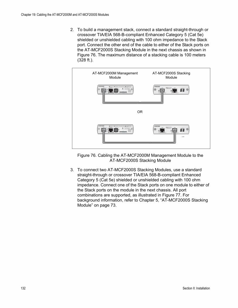
Chapter 19: Cabling the AT-MCF2000M and AT-MCF2000S Modules
2. To build a management stack, connect a standard straight-through or crossover TIA/EIA 568-B-compliant Enhanced Category 5 (Cat 5e) shielded or unshielded cabling with 100 ohm impedance to the Stack port. Connect the other end of the cable to either of the Stack ports on the AT-MCF2000S Stacking Module in the next chassis as shown in Figure 76. The maximum distance of a stacking cable is 100 meters (328 ft.).
Figure 76. Cabling the AT-MCF2000M Management Module to the AT-MCF2000S Stacking Module
3. To connect two AT-MCF2000S Stacking Modules, use a standard straight-through or crossover TIA/EIA 568-B-compliant Enhanced Category 5 (Cat 5e) shielded or unshielded cabling with 100 ohm impedance. Connect one of the Stack ports on one module to either of the Stack ports on the module in the next chassis. All port combinations are supported, as illustrated in Figure 77. For background information, refer to Chapter 5, “AT-MCF2000S Stacking Module” on page 73.
AT-MCF2000SLINK ACT
PORT ACTIVITYSTACK 1 STACK 2
AT-MCF2000SLINK ACT
PORT ACTIVITYSTACK 1 STACK 2
AT-MCF2000MSTACK MANAGEMENT
TERMINAL
10/100/1000BASE-T RS-232
RESET
SD
RDY BUSY
MASTER
POWER
BOOT RDY FAULT
1000 LINK ACT 10/100 LINK ACT FDX HDX COLLINK ACTPORT ACTIVITY
SYSTEM
0
31ID
AT-MCF2000MSTACK MANAGEMENT
TERMINAL
10/100/1000BASE-T RS-232
RESET
SD
RDY BUSY
MASTER
POWER
BOOT RDY FAULT
1000 LINK ACT 10/100 LINK ACT FDX HDX COLLINK ACTPORT ACTIVITY
SYSTEM
0
31ID
CHASSIS ID
CHASSIS ID
1259
OR
AT-MCF2000M ManagementModule
AT-MCF2000S StackingModule
132 Section II: Installation
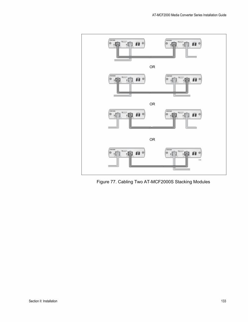
AT-MCF2000 Media Converter Series Installation Guide
Figure 77. Cabling Two AT-MCF2000S Stacking Modules
AT-MCF2000SLINK ACT
PORT ACTIVITYSTACK 1 STACK 2
CHASSIS ID
AT-MCF2000SLINK ACT
PORT ACTIVITYSTACK 1 STACK 2
CHASSIS ID
AT-MCF2000SLINK ACT
PORT ACTIVITYSTACK 1 STACK 2
CHASSIS ID
AT-MCF2000SLINK ACT
PORT ACTIVITYSTACK 1 STACK 2
AT-MCF2000SLINK ACT
PORT ACTIVITYSTACK 1 STACK 2
CHASSIS ID
AT-MCF2000SLINK ACT
PORT ACTIVITYSTACK 1 STACK 2
CHASSIS ID
AT-MCF2000SAT-MCF2000SLINK ACT
PORT ACTIVITYSTACK 1 STACK 2
CHASSIS IDLINK ACT
PORT ACTIVITYSTACK 1 STACK 2
CHASSIS ID
CHASSIS ID
1260
OR
OR
OR
Section II: Installation 133

Chapter 19: Cabling the AT-MCF2000M and AT-MCF2000S Modules
134 Section II: Installation
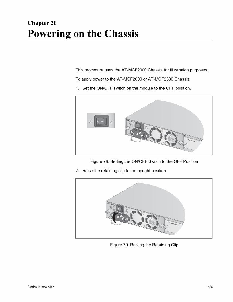
Chapter 20
Powering on the Chassis
This procedure uses the AT-MCF2000 Chassis for illustration purposes.
To apply power to the AT-MCF2000 or AT-MCF2300 Chassis:
1. Set the ON/OFF switch on the module to the OFF position.
Figure 78. Setting the ON/OFF Switch to the OFF Position
2. Raise the retaining clip to the upright position.
Figure 79. Raising the Retaining Clip
AT-MCF2KPNL3
NORMALFAULT
STATUS PSU
FAN
M
A
ONOFF
AT-MCF2KPNL3
NORMALFAULT
STATUS PSU
FAN
M
A
Section II: Installation 135
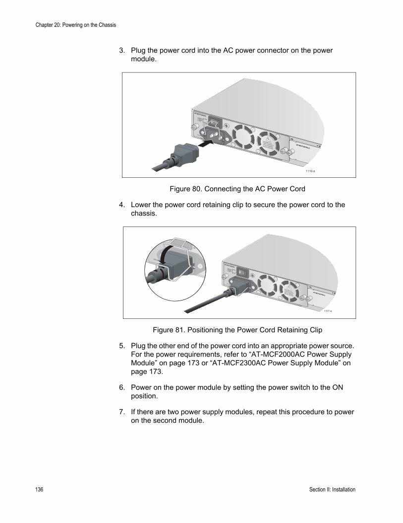
Chapter 20: Powering on the Chassis
3. Plug the power cord into the AC power connector on the power module.
Figure 80. Connecting the AC Power Cord
4. Lower the power cord retaining clip to secure the power cord to the chassis.
Figure 81. Positioning the Power Cord Retaining Clip
5. Plug the other end of the power cord into an appropriate power source. For the power requirements, refer to “AT-MCF2000AC Power Supply Module” on page 173 or “AT-MCF2300AC Power Supply Module” on page 173.
6. Power on the power module by setting the power switch to the ON position.
7. If there are two power supply modules, repeat this procedure to power on the second module.
1116-a
AT-MCF2KPNL3
NORMALFAULT
STATUS PSU
FAN
M
A
1117-a
AT-MCF2KPNL3
NORMALFAULT
STATUS PSU
FAN
M
A
136 Section II: Installation

AT-MCF2000 and AT-MCF2300 Installation Guide
NoteIf the media converter chassis has two power supplies, you can protect it from a power circuit failure by connecting the power cords to outlets on different circuits.
This completes the installation procedure. For instructions on how to verify the operations of the modules in the chassis, refer to the next chapter.
Section II: Installation 137

Chapter 20: Powering on the Chassis
138 Section II: Installation

Chapter 21
Verifying the Installation
The instructions in this chapter are used to verify the proper operations of the modules and should be performed after the initial installation of the chassis or whenever you add or replace modules. The sections are:
❒ “AT-MCF2000AC and AT-MCF2300AC Power Supply Module” on page 140
❒ “AT-MCF2KFAN and AT-MCF2300FAN Modules” on page 140❒ “AT-MCF2012LC, AT-MCF2012LC/1 and AT-MCF2032SP Media
Converter Modules” on page 141❒ “AT-MCF2000M Management Module” on page 142❒ “AT-MCF2000S Stacking Module” on page 142
Section II: Installation 139

Chapter 21: Verifying the Installation
AT-MCF2000AC and AT-MCF2300AC Power Supply Module
To verify the status of the AT-MCF2000AC or AT-MCF2300AC Power Supply Module:
❒ Verify that the PSU LED on the power supply is green. If there are two power supplies in the chassis, the STATUS LEDs should be green on both modules. If the STATUS LED on the power supply is amber or off, refer to “AT-MCF2000AC and AT-MCF2300AC Power Supply Modules” on page 150 for troubleshooting suggestions.
AT-MCF2KFAN and AT-MCF2300FAN Modules
To verify the status of the AT-MCF2KFAN Module:
❒ Verify that the module’s STATUS LED is green. If the STATUS LED is amber or off, refer to “AT-MCF2KFAN and AT-MCF2300FAN Modules” on page 151 for troubleshooting ideas.
To verify the status of the AT-MCF2300FAN Module:
❒ Examine the three FAN LEDs beneath the fans. The LEDs should be green. If the LEDs are off or if they are amber, refer to “AT-MCF2KFAN and AT-MCF2300FAN Modules” on page 151 for troubleshooting suggestions.
140 Section II: Installation

AT-MCF2000 Media Converter Series Installation Guide
AT-MCF2012LC, AT-MCF2012LC/1 and AT-MCF2032SP Media Converter Modules
This procedure explains how to verify the operations of the individual channels on a media converter module, using the Link Test mode and the Link LEDs. The procedure assumes the following:
❒ The media converter chassis is powered on.❒ The network cables are connected to the ports on the media converter
module and to the local and remote network devices.❒ The local and remote network devices are powered on.
To verify the operations of a channel on the media converter module:
1. Turn the Mode button up or down to select a channel, as explained in “Mode Button” on page 51.
2. Set the channel to the Link Test operating mode by pressing the middle of the Mode button until the LT LED is on.
3. Observe the Link LEDs of the twisted pair and fiber optic ports of the channel.
❒ If the Link LEDs for both of the ports in the channel are on, the ports have established links with the local and remote network devices, which may already be forwarding network traffic to each other through the media converter channel. You can either leave the channel in the Link Test mode or, by pressing the middle of the Mode button, change it to the MissingLink or Smart MissingLink mode, indicated by the ML and SML LEDs, respectively. For further information on the operating modes, refer to “Channel Operating Modes” on page 37.
❒ If the Link LED for a port in the channel is off, the port does not have a link to the network device. For suggestions on how to resolve the problem, go to “AT-MCF2012LC, AT-MCF2012LC/1 and AT-MCF2032SP Media Converter Modules” on page 146 in Chapter 23, “Troubleshooting the Modules”.
4. Repeat this procedure to test the other channels.
Section II: Installation 141
Chapter 21: Verifying the Installation
AT-MCF2000M Management Module
To verify the installation of the optional AT-MCF2000M Management Module:
❒ Verify that the Power LED on the module is green.❒ Verify that the System LED is steady or flashing green.❒ If the 10/100/1000Base-T Management port is connected to a network
device, check that the port’s L/A (Link/Activity) LED is steady or flashing green or amber.
❒ If the Stack port is connected to another chassis, verify that the L/A (Link/Activity) LED for the port is steady or flashing green.
If you encounter any problems, refer to “AT-MCF2000M Management Module” on page 153.
AT-MCF2000S Stacking Module
To verify the installation of the optional AT-MCF2000S Stacking Module:
❒ View the Chassis ID LEDs to determine the modules number assignment, set with the DIP switches. If, when you installed the module, you affixed a label with the module’s ID number to its faceplate, compare the number on the Chassis ID LEDs with the number on the label. They should be the same. If they are not, remove the module and reset the DIP switches.
❒ If the Stack ports are connected to other units, verify that the Link/Activity LEDs for the ports are steady or flashing green.
If you encounter any problems, refer to “AT-MCF2000S Stacking Module” on page 155.
142 Section II: Installation

Chapter 22
Starting a Local Management Session
To start a local management session on the optional AT-MCF2000M Management Module:
NoteThe initial management of the AT-MCF2000M Management Module has to be from a local management session.
1. Connect the DIN-8 connector on the RS-232 Serial Management cable included with the AT-MCF2000M Management Module to the RS-232 Terminal port on the management module.
Figure 82. Connecting the RS-232 Serial Management Cable to the RS-232 Terminal Port
2. Connect the DB-9 connector on the management cable to an RS-232 port on a terminal or a PC with a terminal emulator program.
3. Configure the terminal or terminal emulator program as follows:
❒ Baud rate: 115200 bps (The baud rate of the RS-232 Terminal port is adjustable from 9600 to 115200 bps. The default is 115200 bps. To adjust the baud rate, refer to the AT-S85 and AT-S97 Management Software Command Line User’s Guide.)
❒ Data bits: 8❒ Parity: None
1203a
AT-MCF2000MSTACK
MANAGEMENT
TERMINAL
10/100/1000BASE-T
RS-232
RESET
SD
RDYBUSY
MASTERPOWER
BOOTRDY
FAULT
1000 LINKACT 10/100 LINK
ACT
FDX HDXCOL
LINKACT
PORT ACTIVITY AT-MCF2KFAN
NORMALFAULT
STATUS
Section II: Installation 143

Chapter 22: Starting a Local Management Session
❒ Stop bits: 1❒ Flow control: None
NoteThe port settings are for a DEC VT100 or ANSI terminal, or an equivalent terminal emulator program.
NoteIf you reset or power cycle the chassis during a local management session, you’ll see the prompt “Hit any key to stop autoboot” displayed on your screen. This prompt is for manufacturing purposes only and should be ignored. If you inadvertently display the manufacturing prompt (=>), type “bootapp” to launch the management software on the management module.
4. Press Enter.
5. Enter the user name and password of a manager account on the management module. There is a predefined manager account that allows access to all of the parameters on the management and media converter modules. This account has the user name “manager” and the default password “friend.” User names and passwords are case sensitive.
After you have logged on, the local management session starts and the command line interface (CLI) prompt is displayed, as shown in Figure 83.
Figure 83. Command Line Prompt
6. To test the management module and the installation, enter this command to display a list of the modules in the chassis or, if the chassis is part of a management stack, the devices in the stack:
system show cluster
For further information, refer to the AT-S85 and AT-S97 Management Software Command Line User’s Guide.
Allied Telesis AT-MCF2000M - AT-S97<No System Name>
#
144 Section II: Installation

Chapter 23
Troubleshooting the Modules
If you encounter a problem with the product, you may be able to resolve it with the information in the following sections:
❒ “AT-MCF2012LC, AT-MCF2012LC/1 and AT-MCF2032SP Media Converter Modules” on page 146
❒ “AT-MCF2000AC and AT-MCF2300AC Power Supply Modules” on page 150
❒ “AT-MCF2KFAN and AT-MCF2300FAN Modules” on page 151❒ “AT-MCF2000M Management Module” on page 153❒ “AT-MCF2000S Stacking Module” on page 155
Section II: Installation 145
Chapter 23: Troubleshooting the Modules
AT-MCF2012LC, AT-MCF2012LC/1 and AT-MCF2032SP Media Converter Modules
Problem 1: One of the channel LEDs is slowly pulsing. (The channel LEDs are the CH LEDs on the AT-MCF2012LC and AT-MCF2012LC/1 Modules and are the row of unmarked LEDs beneath the fiber optic ports on the AT-MCF2032SP Module.)
Solution: This is normal. The LED pulses to identity the channel currently represented by the LT, ML, SML, CDC, and FDC LEDs. For example, if the channel 4 LED is pulsing, the LEDs are displaying information about twisted pair port 4 and fiber optic port 4, the two ports of channel 4. For more information, refer to “Mode Button” on page 51.
Problem 2: The cables are connected to the ports on the media converter module and the chassis is powered on, but all of the port LEDs are off.
Solution: Try turning the Mode button up or down and afterwards examine the LT, ML, and SML LEDs on the module. One of the LEDs should be on, as well one of the channel LEDs. If the LEDs are off, the module is not receiving power or has failed. Try the following:
❒ Remove the media converter module from the chassis and reinstall it.❒ Determine whether the power supply in the chassis is operating by
listening for the fans. If the fans are not operating, the problem is with the power supply module. Refer to “AT-MCF2000AC and AT-MCF2300AC Power Supply Modules” on page 150 for troubleshooting suggestions.
❒ Install the media converter module in another slot or in another chassis.
❒ Replace the media converter module.
Problem 3: The two ports of a channel are connected to network devices, but the Link LEDs for the ports are off.
Solution: Using the Mode button, set the operating mode of the channel to the Smart MissingLink mode or the Link Test mode. For instructions, refer to “Mode Button” on page 51. Then observe the Link LEDs for the ports of the channel again. If the Link LED for the twisted pair port is off, go to Problem 4. If the Link LED for the fiber optic port is off, go to Problem 5.
146 Section II: Installation
AT-MCF2000 Media Converter Series Installation Guide
Problem 4: The Link LED for the twisted pair port in a channel is off, but the Link LED for the fiber optic port is on or blinking.
Solution: The twisted pair port is unable to establish a link to a network device. Try the following:
❒ Verify that the network device connected to the twisted pair port is powered on and is operating properly.
❒ Verify that the twisted pair cable is securely connected to the port on the media converter channel and to the port on the remote network device.
❒ Verify that the port is connected to the correct twisted pair cable. This is to eliminate the possibility that the port is connected to the wrong network device, such as a powered off device.
❒ Try connecting another network device to the twisted pair port with a different cable. If the twisted pair port is able to establish a link, then the problem is with the cable or the other network device.
❒ If you installed the optional management module in the chassis, use the management software to verify that the port is enabled.
Problem 5: The Link LED of the fiber optic port in a channel is off, but the Link LED of the twisted pair port is on or blinking.
Solution: The fiber optic port is unable to establish a link to a network device. Try the following:
❒ Verify that the network device connected to the fiber optic port is operating properly.
❒ Verify that the fiber optic cable is securely connected to the port on the media converter channel and to the port on the remote network device.
❒ For the AT-MCF2032SP Module, check to be sure that the SFP module is fully inserted in the slot.
❒ Verify that the operating specifications of the fiber optic ports in the channel and on the remote network device are compatible. For the port specifications, refer to “100Base-FX Fiber Optic Ports” on page 175.
❒ Verify that the correct type of fiber optic cabling is being used. For the specifications, refer to “Fiber Optic Ports” on page 36 or “100Base-FX Fiber Optic Ports” on page 175.
❒ Verify that the port is connected to the correct fiber optic cable. This is to eliminate the possibility that the port is connected to the wrong remote network device, such as a powered off device. For background information, refer to “Media Converter Channels” on page 34.
❒ Try connecting another network device to the fiber optic port using a different cable. If the port is able to establish a link, then the problem is with the cable or with the other network device.
Section II: Installation 147
Chapter 23: Troubleshooting the Modules
❒ If you installed the optional management module, use the management software to verify that the port is enabled.
❒ If the remote network device is a management device, use its management firmware to determine whether its port is enabled.
❒ Test the attenuation on the fiber optic cable with a fiber optic tester to determine whether the optical signal is too weak (i.e., sensitivity) or too strong (i.e., maximum input power). The specifications of the fiber optic ports on the AT-MCF2012LC and AT-MCF2012LC/1 Modules are listed in “100Base-FX Fiber Optic Ports” on page 175.
Problem 6: The Link LEDs for the two ports of a channel are on but the network devices are not forwarding traffic to each other through the channel.
Solution: Try the following:
❒ Verify that the twisted pair and fiber optic cables from the two network devices are connected to ports in the same channel. This is to eliminate the possibility that the devices were inadvertently connected to ports in different channels. For background information, refer to “Media Converter Channels” on page 34.
❒ If the network devices are managed devices, use their management firmware to determine whether they are configured and operating properly.
❒ If the network devices are using a spanning tree protocol, the ports on the devices may have been placed in the standby mode if the path is a redundant path.
Problem 7: Two network devices are forwarding traffic through a channel of the media converter module, but performance is slow.
Solution: Try the following:
❒ There might be a duplex mode mismatch between the twisted pair port in the channel and the network device connected to the port. This occurs when a twisted pair port using Auto-Negotiation is connected to a device with a fixed duplex mode of full duplex. If this is the cause of the problem, adjust the duplex mode of the port on the network device or the media converter module so that both ports are using the same duplex mode.
❒ The two network devices connected to the ports in the channel are operating with different duplex modes. As explained in “Guidelines to Using the Media Converter Modules” on page 53, the performance of a channel is enhanced when its two network devices and its two ports all use the same duplex mode.
❒ There could be an intermittent problem with one of the network devices connected to the ports in the channel or with a cable. To determine if this is the problem, set the channel to the Link Test mode
148 Section II: Installation
AT-MCF2000 Media Converter Series Installation Guide
and observe the Link LEDs on the ports. If one of the Link LEDs periodically blinks, the link may be intermittent. See Problem 8 for suggestions on possible causes and resolutions.
Problem 8: A channel is operating in the Link Test mode and the Link LED of a port is blinking.
Solution: This could indicate that the link between the port and the network device is intermittent. Try the following:
❒ Connecting another network device with a different cable to the port. If the Link LED remains steady on, then the problem is with the original cable or the network device.
❒ For the AT-MCF2032SP Module, check to be sure that the SFP module is fully inserted in the slot.
Problem 9: A channel is operating in the Smart MissingLink mode and the Link LEDs for both ports are blinking.
Solution: This can have several possible causes. One possible cause is if the channel is connected to another media converter that also supports the Smart MissingLink mode, forming a chain of media converters. What can happen is if there is a port that cannot establish a link, the Smart MissingLink mode passes the loss to all of the media converters in the chain. To identify the source of the problem, set the operating mode on all of the media converters in the chain to Link Test and then examine the Link LEDs of the ports. The Link LED of the port that cannot establish a link to its network device will be off.
Another possible cause is an intermittent link on one of the ports, perhaps because of a problem with a cable or a network device. To identify which port has the problem, set the channel to the Link Test mode and go to Problem 8.
Section II: Installation 149

Chapter 23: Troubleshooting the Modules
AT-MCF2000AC and AT-MCF2300AC Power Supply Modules
Problem 1: The PSU LED is off.
Solution: The power supply module is not receiving power or has failed. Try the following:
❒ Verify that the module is fully seated in the power supply slot in the chassis.
❒ Verify that the power cord is firmly connected to the power supply module and the power source.
❒ Try connecting the power module to another power source, preferably located on a different circuit.
❒ Verify that the power source is operating properly by plugging a different device into it.
❒ Verify that the power from the power source meets the operating specifications of the power supply module, listed in “AT-MCF2000AC Power Supply Module” on page 173 and “AT-MCF2300AC Power Supply Module” on page 173.
❒ Replace the power supply module.
Problem 2: The PSU LED is amber.
Solution: The power supply module is failing or the power from the power source is not in the range of the operating specifications of the module. Try the following:
❒ Try connecting the power module to another power source, preferably located on a different circuit.
❒ Verify that the power from the power source is within the operating specifications of the power supply module, listed in “AT-MCF2000AC Power Supply Module” on page 173 and “AT-MCF2300AC Power Supply Module” on page 173.
❒ Replace the power supply module.
Problem 3: The FAN LED is amber.
Solution: A fan in the power supply module has failed. Replace the module.
150 Section II: Installation

AT-MCF2000 Media Converter Series Installation Guide
AT-MCF2KFAN and AT-MCF2300FAN Modules
Problem 1: The STATUS LED on the AT-MCF2KFAN Module is off.
Solution: The fan module is not receiving power or has failed. Try the following:
❒ Verify that the module is fully seated in the power supply slot in the chassis.
❒ Replace the fan module with another fan module or with the AT-MCF2000AC Power Supply Module.
Problem 2: The STATUS LED on the AT-MCF2KFAN Module is amber.
Solution: A fan in the module has failed. Replace the module.
Problem 3: The three FAN LEDs on the AT-MCF2300FAN Module are off.
Solution: The fan module is not receiving power or has failed. Try the following:
❒ Verify that the module is fully seated in the slot in the chassis.❒ Replace the module.
Problem 4: One of the FAN LEDs on the AT-MCF2300FAN Module is amber.
Solution: The fan has failed. As a temporary measure while waiting for the replacement module, cover the broken fan with the fan cover mounted on the back panel of the AT-MCF2300 Chassis, as shown in Figure 84 on page 152. The effectiveness of the remaining fans in maintaining proper air flow and cooling in the chassis is increased if the broken fan is covered.
Section II: Installation 151
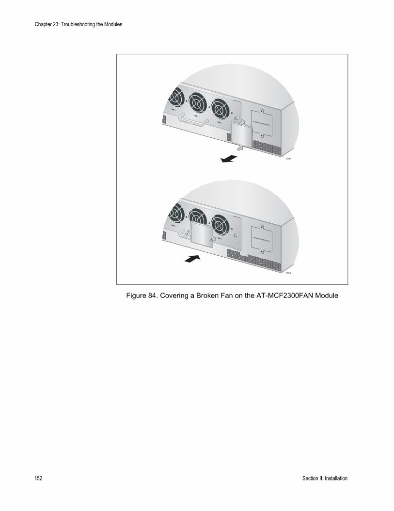
Chapter 23: Troubleshooting the Modules
Figure 84. Covering a Broken Fan on the AT-MCF2300FAN Module
1394
000FAN
FAN 1
FAN 2
FAN 3
1395
000FAN
FAN 1
FAN 2
FAN 3
152 Section II: Installation

AT-MCF2000 Media Converter Series Installation Guide
AT-MCF2000M Management Module
Problem 1: The POWER LED on the module is off.
Solution: Try the following:
❒ Verify that the STATUS LEDs on the power supply modules in the chassis are steady green. If the LEDs are off or signalling a fault condition, refer to “AT-MCF2000AC and AT-MCF2300AC Power Supply Modules” on page 150 for troubleshooting suggestions.
❒ Check that the AT-MCF2000M Management Module is fully inserted into the Management slot in the chassis.
❒ Try replacing the module.
Problem 2: A network cable is connected to the 10/100/1000Base-T Management port, but the port’s Link/Activity LED is off.
Solution: Try the following:
❒ Verify that the network device connected to the Management port is powered on and is operating properly.
❒ Verify that the twisted pair cable is securely connected to the port on the management module and on the network device.
❒ Verify that you are using the correct type of cable for the port and have not exceeded the maximum length. Refer to “10/100/1000Base-T Management Port” on page 59 for the cable specifications.
❒ Try connecting another network device to the port with a different cable. If the port is able to establish a link, then the problem is with the cable or with the other network device.
Problem 3: A twisted pair cable is connected to the Stack port on the management module, but the port’s Link/Activity LED is off.
Solution: Try the following:
❒ Verify that the next chassis in the stack is powered on and is operating properly.
❒ Verify that the twisted pair cable is securely connected to the Stack ports on the management module and on the AT-MCF2000S Stacking Module in the next chassis.
❒ Verify that you are using the correct type of cable for the port and have not exceeded the maximum length. For the cable specifications, refer to “Cabling the Stack Ports” on page 77.
Section II: Installation 153

Chapter 23: Troubleshooting the Modules
Problem 4: You are unable to start a local management session on the management module.
Solutions: Try the following:
❒ Verify that the RS-232 Serial Management Cable is securely connected to the RS-232 Terminal port on the module and to the port on the terminal or personal computer.
❒ Verify that the communications settings for the RS-232 port on the terminal or personal computer are set correctly. For the settings of the RS-232 Terminal port, refer to Chapter 22, “Starting a Local Management Session” on page 143.
Problem 5: A network cable is connected to the 10/100/1000Base-T Management port and the port’s Link/Activity LED is on, but you are unable to start a remote Telnet or SSH management session with the management module.
Solution: Try the following:
❒ Start a local management session on the management module and, using the AT-S97 Management Software, verify that the management module has an IP address configuration. For instructions on how to assign an IP address configuration to the management module, refer to the AT-S85 and AT-S97 Management Software Command Line Interface User’s Guide.
❒ If your remote workstation is not a member of the same network as the management module, verify that the IP address configuration on the module includes a default gateway. This is the IP address of the routing interface of the first hop to reaching the remote network where your management workstation is a member. The default gateway’s IP address must be a member of the same network as the management module.
154 Section II: Installation
AT-MCF2000 Media Converter Series Installation Guide
AT-MCF2000S Stacking Module
Problem 1: The Chassis ID number LEDs are off.
Solution: The AT-MCF2000S Module is not receiving power or has failed. Try the following:
❒ Verify that the STATUS LEDs on the power supply modules in the chassis are steady green. If the LEDs are off or signalling a fault condition, refer to “AT-MCF2000AC and AT-MCF2300AC Power Supply Modules” on page 150 for troubleshooting ideas.
❒ Verify that the AT-MCF2000S Module is fully seated in the Management slot in the chassis.
❒ Remove and reinstall the AT-MCF2000S Module.❒ Replace the module. If the replacement module works, the problem is
with the original module. If the replacement module does not work, the problem is with the chassis.
Problem 2: A cable is connected to a Stack port but the port’s L/A LED is off.
Solution: The Stack port is unable to establish a link with the Stack port in the AT-MCF2000M Module or the AT-MCF2000S Module in the next chassis. Try the following:
❒ Check that the cable is firmly connected to the Stack ports on both chassis.
❒ Verify that the next chassis in the stack is powered on and is operating properly.
❒ Verify that the cable does not exceed 100 meters (328 feet).❒ Check that the cable is a standard straight-through or crossover TIA/
EIA 568-B-compliant Enhanced Category 5 (Cat 5e) shielded or unshielded cable with 100 ohm impedance.
Section II: Installation 155

Chapter 23: Troubleshooting the Modules
156 Section II: Installation
Chapter 24
Replacing the Modules
To remove or replace a module, perform the appropriate procedure in this chapter:❒ “Replacing a Media Converter Module” on page 158❒ “Replacing the AT-MCF2000M or AT-MCF2000S Module” on
page 161❒ “Replacing the AT-MCF2000AC or AT-MCF2300AC Power Supply” on
page 164❒ “Replacing the AT-MCF2300FAN Module” on page 168
NoteAll of the modules in the AT-MCF2000 Series support hot swapping. You do not have to power off the chassis to remove or install a new module.
NoteUnused chassis slots should be kept covered with the AT-MCF2KPNL Slot Covers to prevent dust from entering the unit and to ensure proper airflow and cooling in the enclosure.
Section II: Installation 157
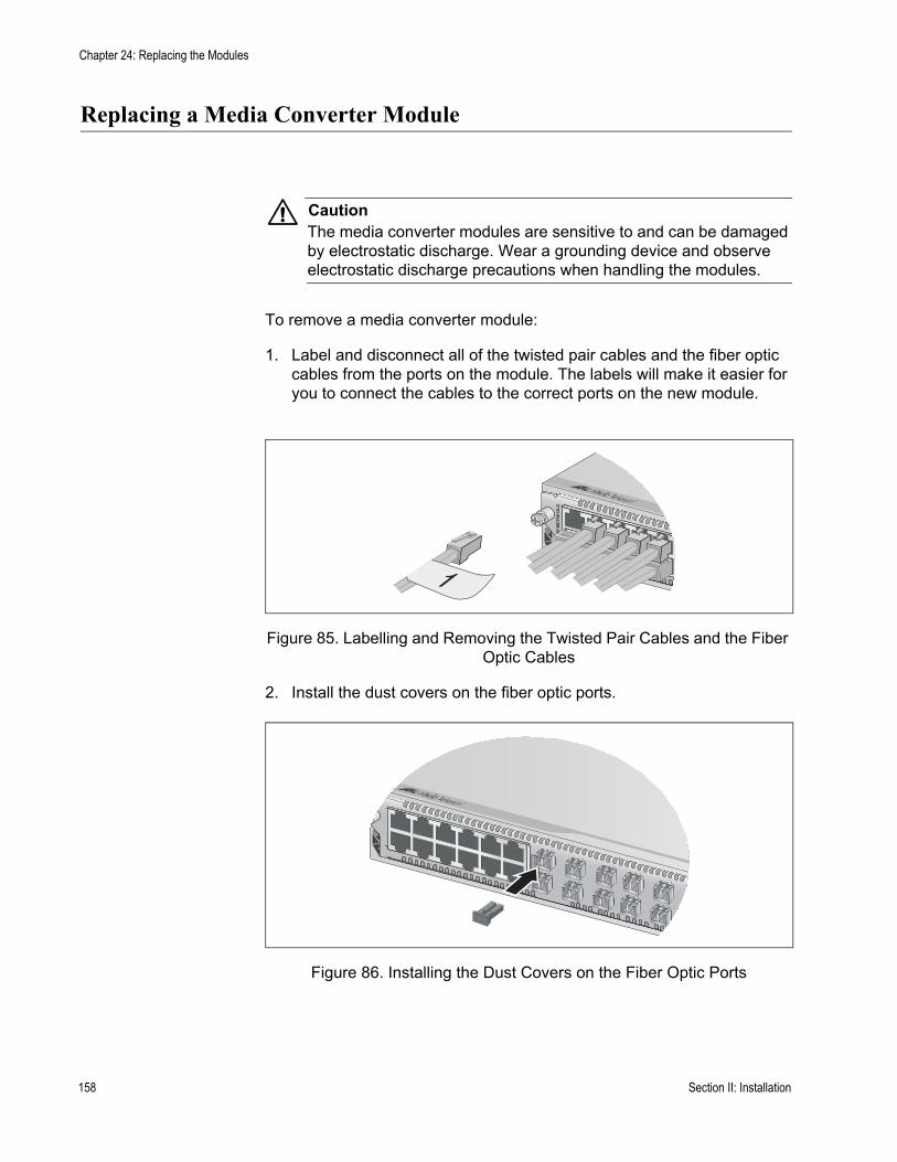
Chapter 24: Replacing the Modules
Replacing a Media Converter Module
CautionThe media converter modules are sensitive to and can be damaged by electrostatic discharge. Wear a grounding device and observe electrostatic discharge precautions when handling the modules.
To remove a media converter module:
1. Label and disconnect all of the twisted pair cables and the fiber optic cables from the ports on the module. The labels will make it easier for you to connect the cables to the correct ports on the new module.
Figure 85. Labelling and Removing the Twisted Pair Cables and the Fiber Optic Cables
2. Install the dust covers on the fiber optic ports.
Figure 86. Installing the Dust Covers on the Fiber Optic Ports
AT-
MC
F20
12L
C
1
158 Section II: Installation
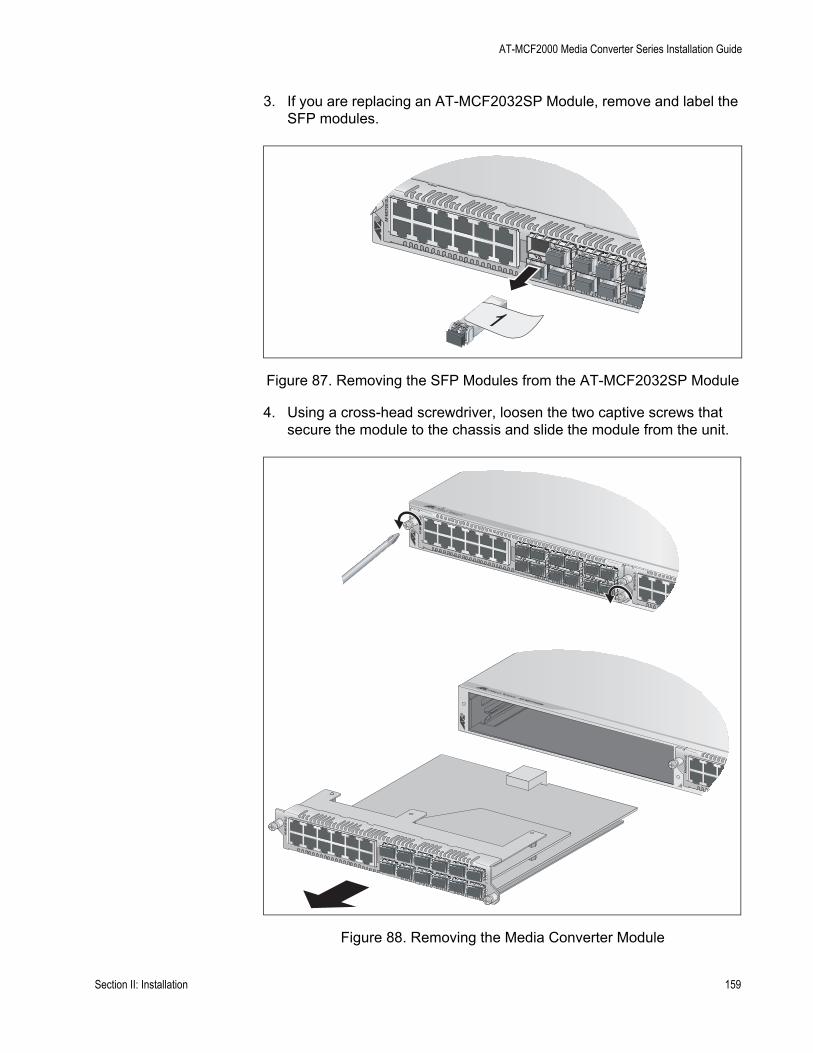
AT-MCF2000 Media Converter Series Installation Guide
3. If you are replacing an AT-MCF2032SP Module, remove and label the SFP modules.
Figure 87. Removing the SFP Modules from the AT-MCF2032SP Module
4. Using a cross-head screwdriver, loosen the two captive screws that secure the module to the chassis and slide the module from the unit.
Figure 88. Removing the Media Converter Module
AT-
MC
F20
12L
C
1
1
AT-
MC
F20
12L
C
AT-
MC
F20
12L
C
AT-
MC
F20
12L
C
1
AT-MCF2000
AT-
MC
F20
12L
C
Section II: Installation 159
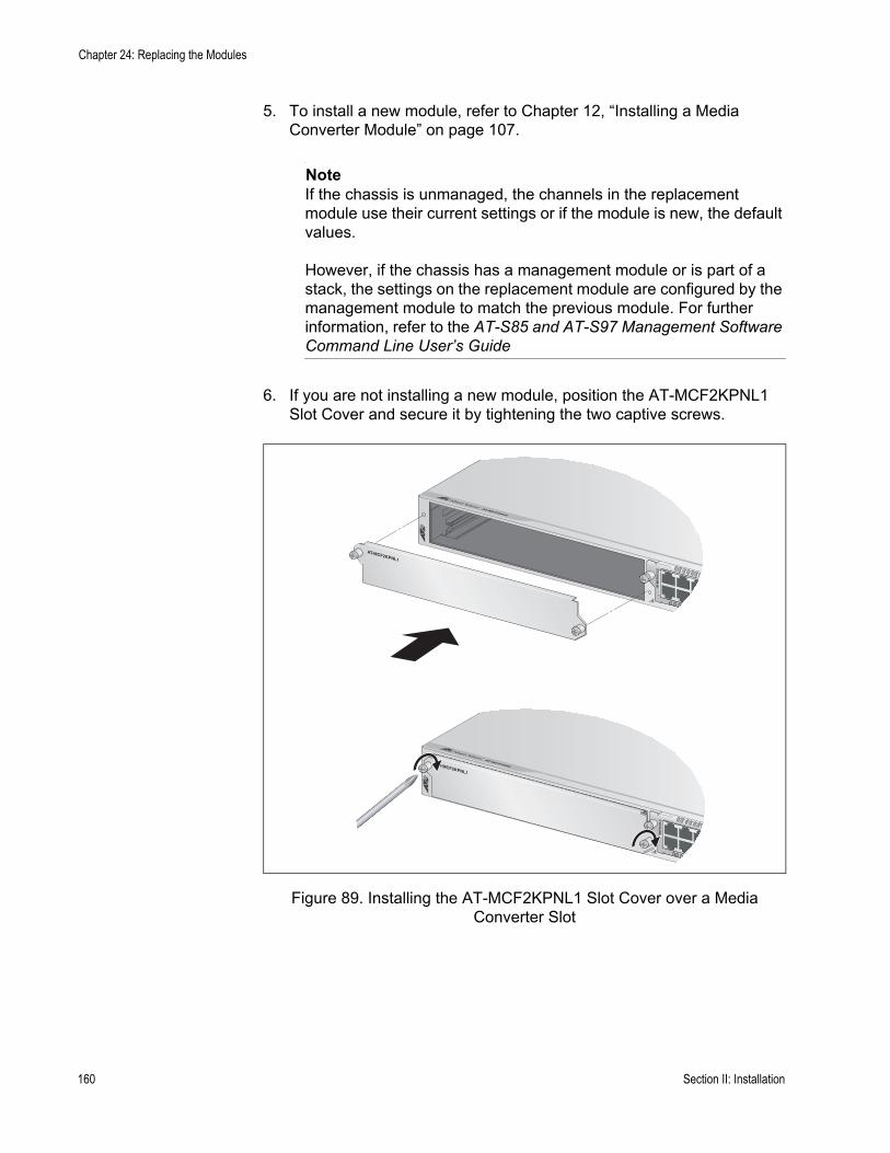
Chapter 24: Replacing the Modules
5. To install a new module, refer to Chapter 12, “Installing a Media Converter Module” on page 107.
NoteIf the chassis is unmanaged, the channels in the replacement module use their current settings or if the module is new, the default values.
However, if the chassis has a management module or is part of a stack, the settings on the replacement module are configured by the management module to match the previous module. For further information, refer to the AT-S85 and AT-S97 Management Software Command Line User’s Guide
6. If you are not installing a new module, position the AT-MCF2KPNL1 Slot Cover and secure it by tightening the two captive screws.
Figure 89. Installing the AT-MCF2KPNL1 Slot Cover over a Media Converter Slot
1
AT-MCF2000
AT-
MC
F20
12L
C
AT-MCF2KPNL1
1
AT-MCF2000
AT-
MC
F20
12L
C
AT-MCF2KPNL1
160 Section II: Installation
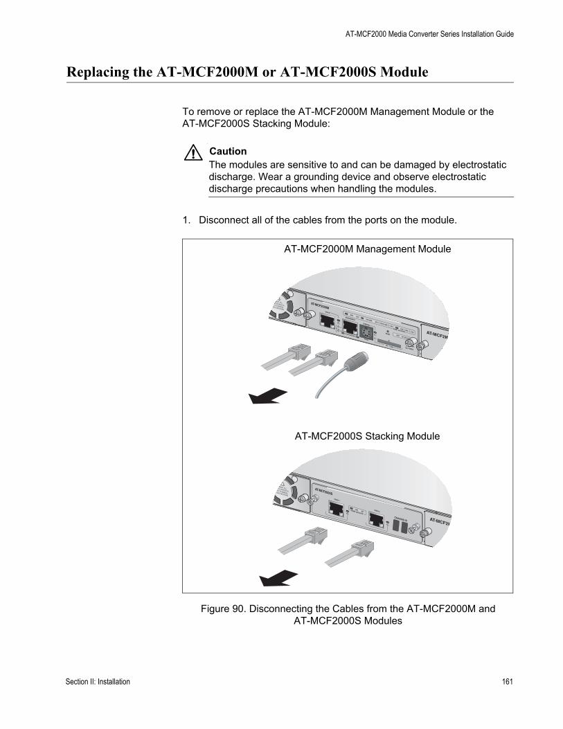
AT-MCF2000 Media Converter Series Installation Guide
Replacing the AT-MCF2000M or AT-MCF2000S Module
To remove or replace the AT-MCF2000M Management Module or the AT-MCF2000S Stacking Module:
CautionThe modules are sensitive to and can be damaged by electrostatic discharge. Wear a grounding device and observe electrostatic discharge precautions when handling the modules.
1. Disconnect all of the cables from the ports on the module.
Figure 90. Disconnecting the Cables from the AT-MCF2000M and AT-MCF2000S Modules
AT-MCF2000MSTACK
MANAGEMENT
TERMINAL
10/100/1000BASE-T
RS-232
RESET
SD
RDYBUSY
MASTERPOWER
BOOTRDY
FAULT
1000 LINKACT 10/100 LINK
ACT
FDX HDXCOL
LINKACT
PORT ACTIVITY AT-MCF2KF
NF
ST
0
31
ID
AT-MCF2000S
WER
LINKACT
PORT ACTIVITY
STACK 1
CHASSIS ID AT-MCF2KF
NF
ST
STACK 2
AT-MCF2000M Management Module
AT-MCF2000S Stacking Module
Section II: Installation 161

Chapter 24: Replacing the Modules
2. Using a cross-head screwdriver, loosen the two captive screws that secure the module to the chassis and slide out the module.
Figure 91. Removing the AT-MCF2000M Management Module or the AT-MCF2000S Stacking Module
3. To install a replacement module, refer to Chapter 13, “Installing the AT-MCF2000M Management Module” on page 111 or Chapter 14, “Installing the AT-MCF2000S Stacking Module” on page 115.
AT-MCF2000MSTACK
MANAGEMENT
TERMINAL
10/100/1000BASE-T
RS-232
RESET
SD
RDYBUSY
MASTERPOWER
BOOTRDY
FAULT
1000 LINKACT 10/100 LINK
ACT
FDX HDXCOL
LINKACT
PORT ACTIVITY AT-MCF2KF
NF
ST
0
31
ID
AT-MCF2KFA
NORFAU
STAT
STACK
MANAGEMENT
TERMINAL
10/100/1000BASE-T
RS-232
RESET
SD
RDYBUSY
MASTER
POWER
BOOTRDY
FAULT
1000 LINKACT
10/100 LINKACT
FDXHDX
COL
LINKACT
PORT ACTIVITY
162 Section II: Installation
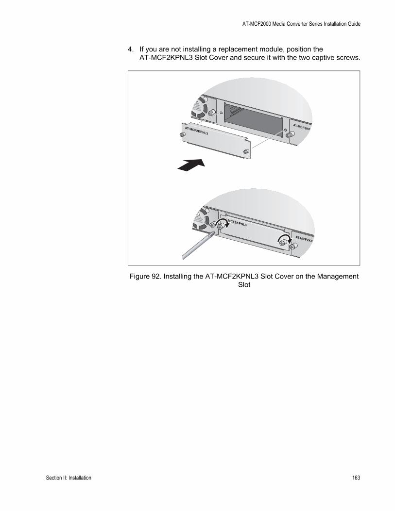
AT-MCF2000 Media Converter Series Installation Guide
4. If you are not installing a replacement module, position the AT-MCF2KPNL3 Slot Cover and secure it with the two captive screws.
Figure 92. Installing the AT-MCF2KPNL3 Slot Cover on the Management Slot
AT-MCF2KFAN
NORMAFAULT
STATU
AT-MCF2KPNL3
AT-MCF2KFAN
NORMAFAULT
STATU
AT-MCF2KPNL3
Section II: Installation 163
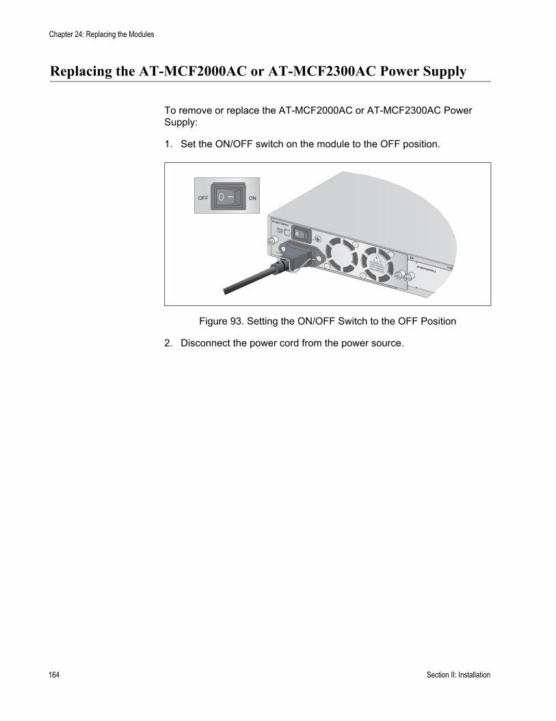
Chapter 24: Replacing the Modules
Replacing the AT-MCF2000AC or AT-MCF2300AC Power Supply
To remove or replace the AT-MCF2000AC or AT-MCF2300AC Power Supply:
1. Set the ON/OFF switch on the module to the OFF position.
Figure 93. Setting the ON/OFF Switch to the OFF Position
2. Disconnect the power cord from the power source.
AT-MCF2KPNL3
NORMALFAULT
STATUS PSU
FAN
M
A
ONOFF
164 Section II: Installation

AT-MCF2000 Media Converter Series Installation Guide
3. Raise the retaining clip and disconnect the power cord from the module.
Figure 94. Removing the Power Cord
AT-MCF2KPNL3
NORMALFAULT
STATUS PSU
FAN
M
A
AT-MCF2KPNL3
NORMALFAULT
STATUS PSU
FAN
M
A
Section II: Installation 165
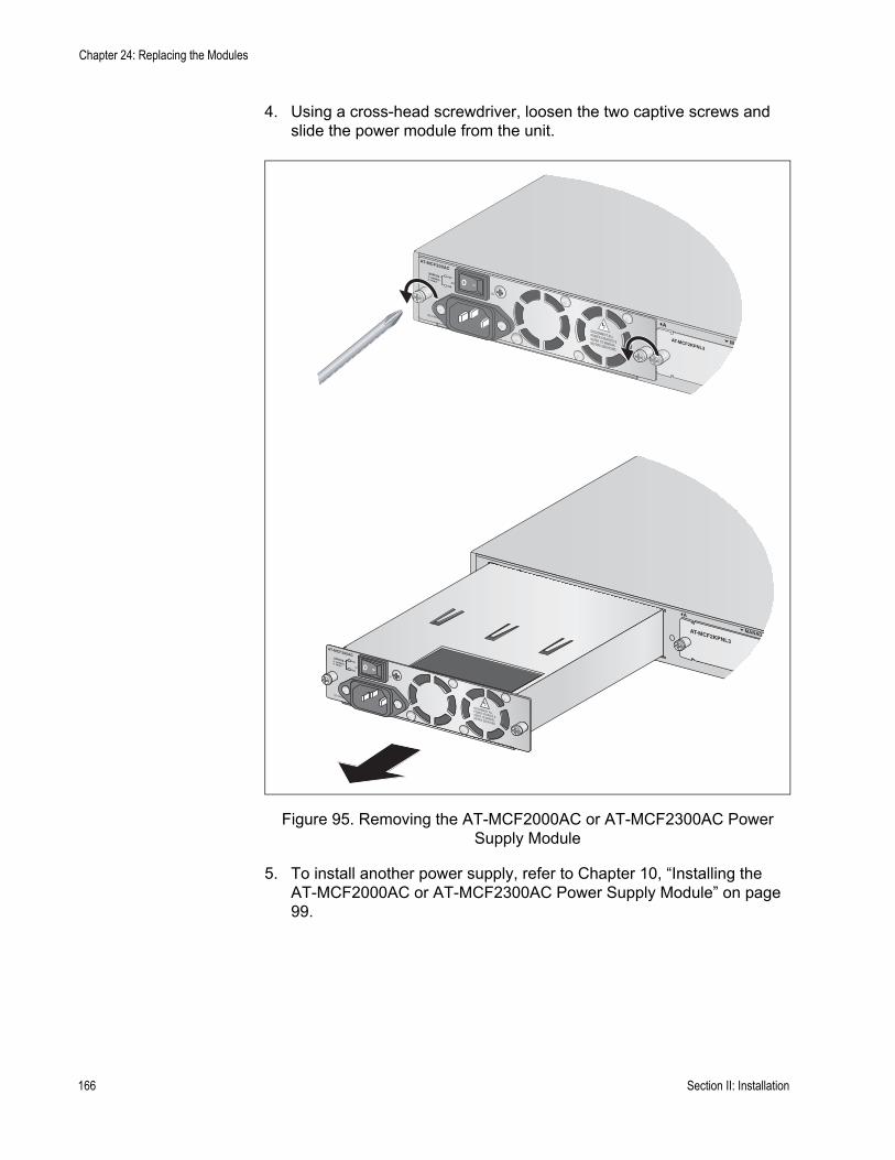
Chapter 24: Replacing the Modules
4. Using a cross-head screwdriver, loosen the two captive screws and slide the power module from the unit.
Figure 95. Removing the AT-MCF2000AC or AT-MCF2300AC Power Supply Module
5. To install another power supply, refer to Chapter 10, “Installing the AT-MCF2000AC or AT-MCF2300AC Power Supply Module” on page 99.
AT-MCF2KPNL3
NORMALFAULT
STATUS PSU
FAN
M
A
AT-MCF2KPNL3
NORMALFAULT
STATUS PSU
FAN
MANAG
A
166 Section II: Installation
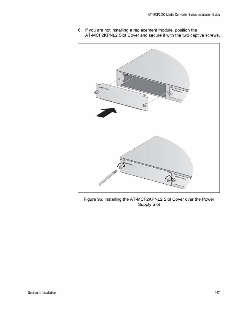
AT-MCF2000 Media Converter Series Installation Guide
6. If you are not installing a replacement module, position the AT-MCF2KPNL2 Slot Cover and secure it with the two captive screws.
Figure 96. Installing the AT-MCF2KPNL2 Slot Cover over the Power Supply Slot
AT-MCF2KPNL3MA
AAT-MCF2KPNL2
AT-MCF2KPNL3MA
A
AT-MCF2KPNL2
Section II: Installation 167
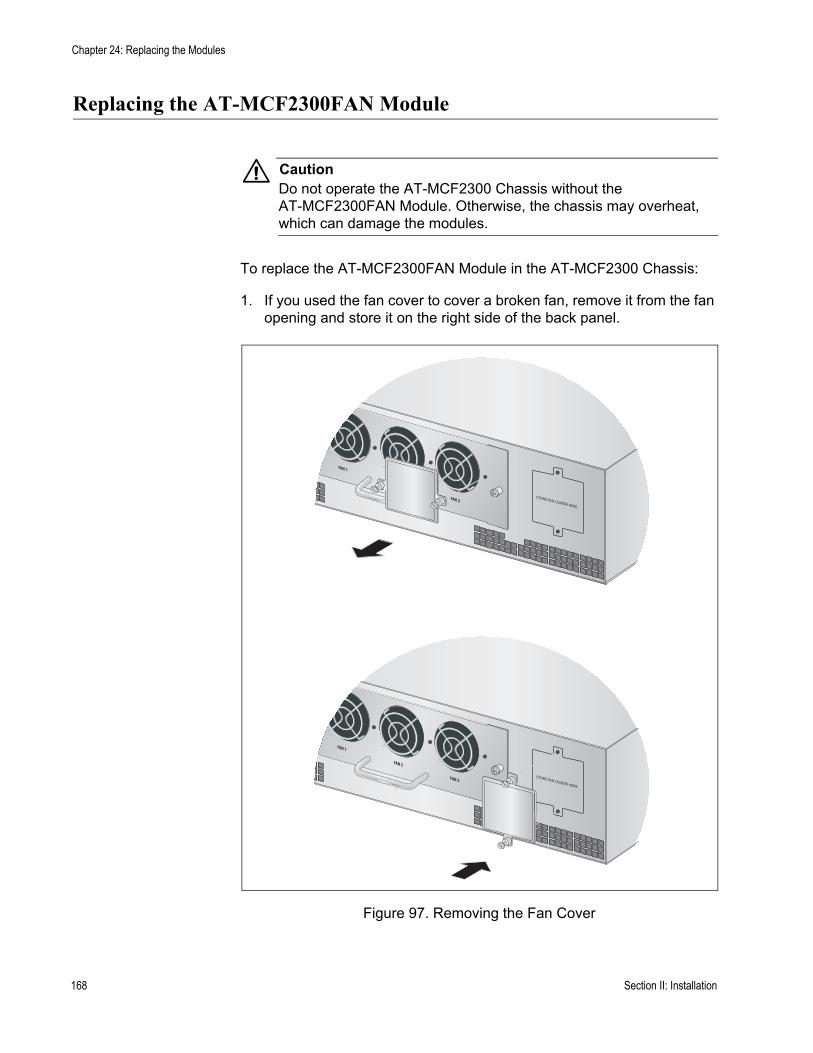
Chapter 24: Replacing the Modules
Replacing the AT-MCF2300FAN Module
CautionDo not operate the AT-MCF2300 Chassis without the AT-MCF2300FAN Module. Otherwise, the chassis may overheat, which can damage the modules.
To replace the AT-MCF2300FAN Module in the AT-MCF2300 Chassis:
1. If you used the fan cover to cover a broken fan, remove it from the fan opening and store it on the right side of the back panel.
Figure 97. Removing the Fan Cover
000FAN
FAN 1
FAN 2
FAN 3
000FAN
FAN 1
FAN 2
FAN 3
168 Section II: Installation
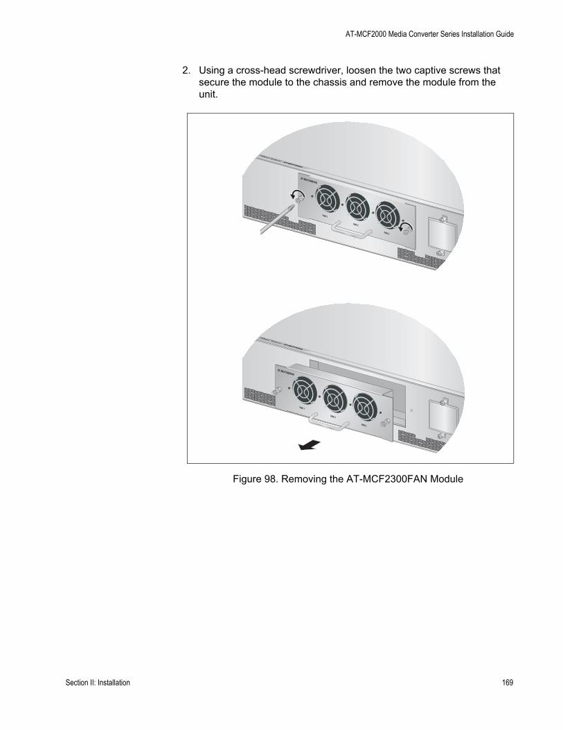
AT-MCF2000 Media Converter Series Installation Guide
2. Using a cross-head screwdriver, loosen the two captive screws that secure the module to the chassis and remove the module from the unit.
Figure 98. Removing the AT-MCF2300FAN Module
AT-MCF2000
AT-MCF2000FAN
FAN 1
FAN 2
FAN 3
AT-MCF2000
AT-MCF2000FAN
FAN 1
FAN 2
FAN 3
Section II: Installation 169
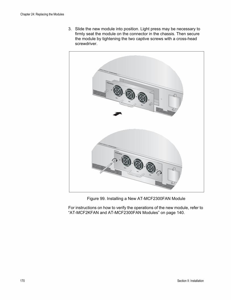
Chapter 24: Replacing the Modules
3. Slide the new module into position. Light press may be necessary to firmly seat the module on the connector in the chassis. Then secure the module by tightening the two captive screws with a cross-head screwdriver.
Figure 99. Installing a New AT-MCF2300FAN Module
For instructions on how to verify the operations of the new module, refer to “AT-MCF2KFAN and AT-MCF2300FAN Modules” on page 140.
AT-MCF2000
AT-MCF2000FAN
FAN 1
FAN 2
FAN 3
AT-MCF2000
AT-MCF2000FAN
FAN 1
FAN 2
FAN 3
170 Section II: Installation

Appendix A
Technical Specifications
Environmental Specifications
Operating Temperature: 0° C to 40° C(32° F to 104° F)
Storage Temperature: -20° C to 70° C(-° 4F to 158° F)
Operating Humidity: Less than 80% noncondensing
Storage Humidity: Less than 95% noncondensing
Maximum Operating Altitude: 3,048 m (10,000 ft)
Maximum Non-operatingAltitude: 4,000 m (13,000 ft)
Standards
IEEE 802.3 10Base-T
IEEE 802.3u 100Base-TX
IEEE 802.3u 100Base-TX
IEEE 802.3u 100Base-FX compliant
IEEE 802.3ab 1000Base-T (AT-MCF2032SP Module)
IEEE 802.3u Auto-Negotiation on the twisted pair ports
171

Appendix A: Technical Specifications
Safety and Electromagnetic Emissions Certifications
EMI (Emissions): FCC Class A, EN55022 Class A, EN61000-3-2, EN61000-3-3, VCCI Class A, C-TICK, CE
EMC (Immunity): EN55024
Electrical and Laser Safety: EN60950-1 (TUV), UL 60950-1 (CULUS), EN60825
Compliance Marks: CE, CULUS, TUV, C-Tick
AT-MCF2000 Chassis
Dimensions: 4.4 x 44.0 x 42.4 cm(1.75 x 17.3 x 16.7 in.)(H x W x D)
Weight — Chassis with blank faceplates: 5.5 kg (12.0 lb.)
Weight — Chassis with twoAT-MCF2000AC Modulesand two AT-MCF2012LCModules: 7.7 kg (17.0 lb.)
MTBF: 220,000 hrs
AT-MCF2300 Chassis
Dimensions: 12.9 x 44.0 x 25.4 cm(5.1 x 17.3 x 10.0 in.)(H x W x D)
Weight — Chassis with blank faceplates: 7.25 kg (16 lb.)
Weight — Chassis with twoAT-MCF2300AC Modulesand four AT-MCF2012LCModules: 13.45 kg (29.6 lb.)
MTBF: 270,000 hrs
172

AT-MCF2000 Media Converter Series Installation Guide
AT-MCF2000AC Power Supply Module
Dimensions: 4.1 x 13.3 x 20.6 cm(1.6 x 5.3 x 8.1 in.)(H x W x D)
Weight: 1.25 kg (2.75 lb.)
Input Voltage: 100-240 VAC 50/60 Hz
Output Voltages: 12 volts and 3.3 volts
Maximum Input Current: 2A
Power Consumption: 100 W (maximum)
MTBF: 140,000
AT-MCF2300AC Power Supply Module
Dimensions: 4.1 x 13.3 x 20.6 cm(1.6 x 5.3 x 8.1 in.)(H x W x D)
Weight: 1.41 kg (3.1 lb.)
Input Voltage: 100-240 VAC 50/60 Hz
Output Voltages: 12 volts and 3.3 volts
Maximum Input Current: 2.5A
Power Consumption: 200W (maximum)
MTBF: 150,000
173

Appendix A: Technical Specifications
AT-MCF2012LC, AT-MCF2012LC/1 and AT-MCF2032SP Media Converter Modules
Specifications Dimensions: 3.2 x 20.6 x 16.5 cm(1.26 x 8.1 x 6.5 in.)(H x W x D)
Weight - AT-MCF2012LCand AT-MCF2012LC/1: 685 g (1.50 lb.)
Weight - AT-MCF2032SP: 0.78 kg (1.71 lb.)
Input Voltage: 12 volts and 3.3 volts
Maximum Input Current: 3 amperes
Maximum Power Consumption: 36 watts
MTBF - AT-MCF2012LCand AT-MCF2012LC/1: 300,000 hrs.
MTBF - AT-MCF2032SP: 220,000 hrs.
Twisted Pair PortPinouts
Table 32 lists the pins and their signals when the twisted pair ports are operating in MDI or MDI-X configuration at 10 or 100 Mbps.
Table 29. 10/100Base-TX Port Pinouts
Pin MDI Signal MDI-X Signal
1 TX+ RX+
2 TX- RX-
3 RX+ TX+
6 RX- TX-
174
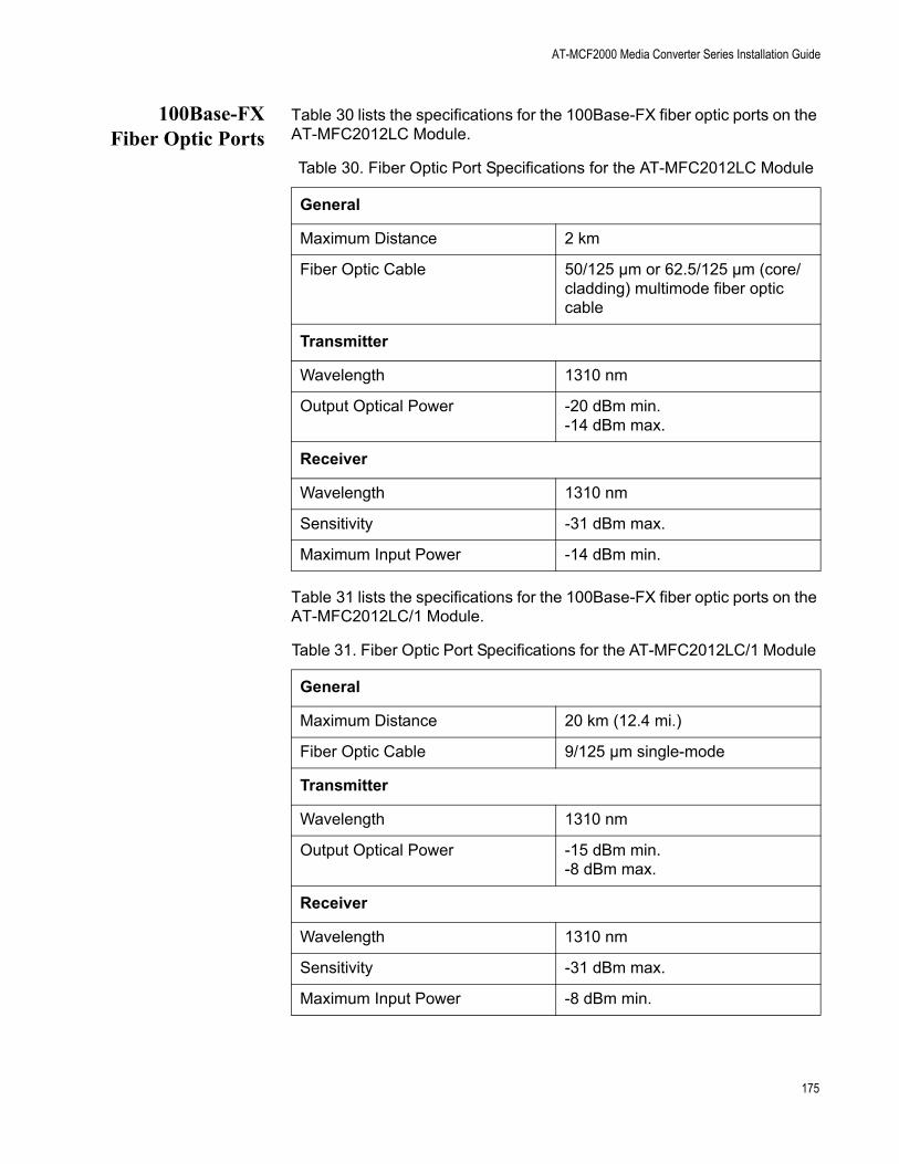
AT-MCF2000 Media Converter Series Installation Guide
100Base-FXFiber Optic Ports
Table 30 lists the specifications for the 100Base-FX fiber optic ports on the AT-MFC2012LC Module.
Table 31 lists the specifications for the 100Base-FX fiber optic ports on the AT-MFC2012LC/1 Module.
Table 30. Fiber Optic Port Specifications for the AT-MFC2012LC Module
General
Maximum Distance 2 km
Fiber Optic Cable 50/125 µm or 62.5/125 µm (core/cladding) multimode fiber optic cable
Transmitter
Wavelength 1310 nm
Output Optical Power -20 dBm min.-14 dBm max.
Receiver
Wavelength 1310 nm
Sensitivity -31 dBm max.
Maximum Input Power -14 dBm min.
Table 31. Fiber Optic Port Specifications for the AT-MFC2012LC/1 Module
General
Maximum Distance 20 km (12.4 mi.)
Fiber Optic Cable 9/125 µm single-mode
Transmitter
Wavelength 1310 nm
Output Optical Power -15 dBm min.-8 dBm max.
Receiver
Wavelength 1310 nm
Sensitivity -31 dBm max.
Maximum Input Power -8 dBm min.
175

Appendix A: Technical Specifications
AT-MCF2000M Management Module
Specifications Dimensions: 3.1 x 9.7 x 20.8 cm(1.2 x 3.8 x 8.2 in.)(H x W x D)
Weight: 340 g (0.75 lb.)
MTBF: 590,000 hrs
10/100/1000Base-T Port Pin-outs
Figure 100 identifies the location of pin 1 on the connector.
Figure 100. RJ-45 Connector and Port Pin Assignments
Table 32 lists the pins signals in the MDI and MDI-X configurations at 10 or 100 Mbps.
Table 33 lists the pin signals when the management port is operating at 1000 Mbps.
Table 32. 10/100/1000Base-T Management Port Pinouts at 10 or 100 Mbps
Pin MDI Signal MDI-X Signal
1 TX+ RX+
2 TX- RX-
3 RX+ TX+
6 RX- TX-
Table 33. 10/100/1000Base-T Management Port Pinouts at 1000 Mbps
Pin Pair
1 Pair 1 +
2 Pair 1 -
3 Pair 2 +
Pin 1
176

AT-MCF2000 Media Converter Series Installation Guide
RS-232 TerminalPort Pinouts
Figure 101 illustrates the pin layouts for the DIN-8 connector and port of the RS-232 Terminal port.
Figure 101. RS-232 Terminal Port Pinouts
Table 34 lists the pin signals for the RS-232 Terminal port.
4 Pair 3 +
5 Pair 3 -
6 Pair 2 -
7 Pair 4 +
8 Pair 4 -
Table 33. 10/100/1000Base-T Management Port Pinouts at 1000 Mbps
Table 34. RS-232 Terminal Port
Pin Signal
1 NC
2 DTR
3 TX
4 RX
5 DSR
6 GND
7 RTS
8 CTS
1 2
3 4 5
6 7 8
2 1
3
45
6
7
8
158
177
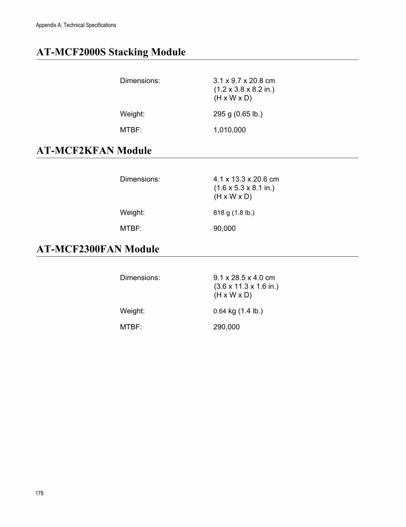
Appendix A: Technical Specifications
AT-MCF2000S Stacking Module
Dimensions: 3.1 x 9.7 x 20.8 cm(1.2 x 3.8 x 8.2 in.)(H x W x D)
Weight: 295 g (0.65 lb.)
MTBF: 1,010,000
AT-MCF2KFAN Module
Dimensions: 4.1 x 13.3 x 20.6 cm(1.6 x 5.3 x 8.1 in.)(H x W x D)
Weight: 818 g (1.8 lb.)
MTBF: 90,000
AT-MCF2300FAN Module
Dimensions: 9.1 x 28.5 x 4.0 cm(3.6 x 11.3 x 1.6 in.)(H x W x D)
Weight: 0.64 kg (1.4 lb.)
MTBF: 290,000
178
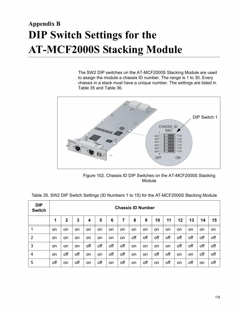
Appendix B
DIP Switch Settings for the AT-MCF2000S Stacking Module
The SW2 DIP switches on the AT-MCF2000S Stacking Module are used to assign the module a chassis ID number. The range is 1 to 30. Every chassis in a stack must have a unique number. The settings are listed in Table 35 and Table 36.
Figure 102. Chassis ID DIP Switches on the AT-MCF2000S Stacking Module
AT-MCF2000S
STACK 1
LINKACTPORT ACTIVITY STACK 2
CHASSIS ID
1400
OFF ON6
1
CHASSIS_IDSW2
DIP Switch 1
Table 35. SW2 DIP Switch Settings (ID Numbers 1 to 15) for the AT-MCF2000S Stacking Module
DIP Switch Chassis ID Number
1 2 3 4 5 6 7 8 9 10 11 12 13 14 15
1 on on on on on on on on on on on on on on on
2 on on on on on on on off off off off off off off off
3 on on on off off off off on on on on off off off off
4 on off off on on off off on on off off on on off off
5 off on off on off on off on off on off on off on off
179

Appendix B: DIP Switch Settings for the AT-MCF2000S Stacking Module
NoteDIP switch 6 is not used.
Table 36. SW2 DIP Switch Settings (ID Numbers 16 to 30) for the AT-MCF2000S Stacking Module
DIP Switch Chassis ID Number
16 17 18 19 20 21 22 23 24 25 26 27 28 29 30
1 off off off off off off off off off off off off off off off
2 on on on on on on on on off off off off off off off
3 on on on on off off off off on on on on off off off
4 on on off off on on off off on on off off on on off
5 on off on off on off on off on off on off on off on
180
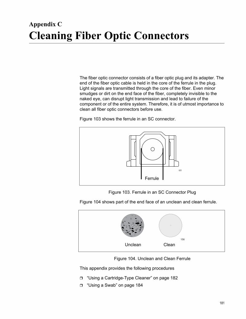
Appendix C
Cleaning Fiber Optic Connectors
The fiber optic connector consists of a fiber optic plug and its adapter. The end of the fiber optic cable is held in the core of the ferrule in the plug. Light signals are transmitted through the core of the fiber. Even minor smudges or dirt on the end face of the fiber, completely invisible to the naked eye, can disrupt light transmission and lead to failure of the component or of the entire system. Therefore, it is of utmost importance to clean all fiber optic connectors before use.
Figure 103 shows the ferrule in an SC connector.
Figure 103. Ferrule in an SC Connector Plug
Figure 104 shows part of the end face of an unclean and clean ferrule.
Figure 104. Unclean and Clean Ferrule
This appendix provides the following procedures
“Using a Cartridge-Type Cleaner” on page 182“Using a Swab” on page 184
177
Ferrule
156
Unclean Clean
181
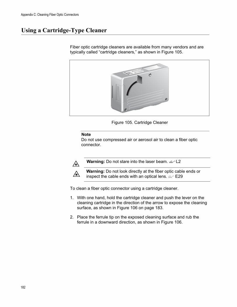
Appendix C: Cleaning Fiber Optic Connectors
Using a Cartridge-Type Cleaner
Fiber optic cartridge cleaners are available from many vendors and are typically called “cartridge cleaners,” as shown in Figure 105.
Figure 105. Cartridge Cleaner
NoteDo not use compressed air or aerosol air to clean a fiber optic connector.
To clean a fiber optic connector using a cartridge cleaner.
1. With one hand, hold the cartridge cleaner and push the lever on the cleaning cartridge in the direction of the arrow to expose the cleaning surface, as shown in Figure 106 on page 183.
2. Place the ferrule tip on the exposed cleaning surface and rub the ferrule in a downward direction, as shown in Figure 106.
Warning: Do not stare into the laser beam. L2
Warning: Do not look directly at the fiber optic cable ends or inspect the cable ends with an optical lens. E29
TAPE A WipingDirection
PU
SH
OP
EN
PU
SH
OP
EN
182

AT-MCF2000 Media Converter Series Installation Guide
Figure 106. Rubbing the Ferrule Tip on the Cleaning Surface
NoteRub the ferrule tip on the cleaning surface in one direction only.
3. When you reach the end of the cleaning surface, pick up the ferrule tip, rotate and place it at the top and rub downwards at least 2 times.
CautionFailing to pick up the ferrule tip when you reach the bottom of the cleaning surface can result in static electricity that can damage the fiber optic cable.
4. If desired, repeat steps 3 and 4.
5. If a fiber inspection scope is available, use the scope to inspect the ferrule end face to make sure that it is clean.
6. Reconnect the cable to the port or protect the ferrule tip with a dust cap.
NoteAlways keep a dust cap on a fiber optic cable when it is not in use.
NoteDo not touch the end face of the ferrule in the connector.
183

Appendix C: Cleaning Fiber Optic Connectors
Using a Swab
Specially treated swabs (stick cleaners) are available for cleaning inside connector adapters or hard-to-reach ferrule tips. These swabs, often referred to as “lint free” or “alcohol free” swabs, are available from many vendors, as shown in Figure 107. Stick cleaners are available in both 2.5 mm and 1.25 mm sizes for use on SC and MU connectors respectively.
NoteNEVER use a household cotton swab and/or alcohol to clean a fiber optic connector. This may leave a residue on the ferrule tip.
Figure 107. Lint-Free and Alcohol-Free Swabs
NoteDo not use compressed air or aerosol air to clean a fiber optic connector.
To clean a recessed ferrule using a swab.
1. Insert the swab into the adapter as shown in Figure 108 and rub the ferrule tip with the swab.
Figure 108. Cleaning a Recessed Ferrule
Warning: Do not stare into the laser beam. L2
Warning: Do not look directly at the fiber optic cable ends or inspect the cable ends with an optical lens. E29
157
184

AT-MCF2000 Media Converter Series Installation Guide
2. If desired, repeat step 1.
3. If a fiber inspection scope is available, use the scope to inspect the connector to make sure that it is clean and to check for scratches, pits, or other problems that may affect performance.
NoteAlways keep a dust cap on a fiber optic cable when it is not in use.
NoteDo not touch the end face of the ferrule in the connector.
185

Appendix C: Cleaning Fiber Optic Connectors
186

Index
Numerics10/100/1000Base-T Management Port
cabling 131described 59LEDs 69pinouts 176
AActivity LEDs 41AT-MCF2000 Chassis
described 28installing, in equipment rack 119technical specifications 172unpacking 93
AT-MCF2000AC Power Supply Moduleinstalling 99technical specifications 173troubleshooting 150verifying operations 140
AT-MCF2000M Management Modulecabling 131chassis ID jumper 66described 56installing 111LEDs 67removing 161Reset button 63RS-232 Terminal Port 61SD slot 65Stack port 62technical specifications 176troubleshooting 153verifying operations 142
AT-MCF2000S Stacking Modulecabling 131chassis ID numbers 79described 74guidelines 83installing 115LEDs 81, 82maximum number of media converter modules 76removing 161setting chassis ID numbers 116, 179technical specifications 178topology 75troubleshooting 155verifying operations 142
AT-MCF2012LC Media Converter Modulecabling 129channel operating modes 37channels 34fiber optic ports 36front panel 33guidelines 53installing 107LEDs 41Mode button 51removing 158technical specifications 174troubleshooting 146twisted pair ports 35verifying operations 141
AT-MCF2012LC/1 Media Converter Modulecabling 129channel operating modes 37channels 34fiber optic ports 36front panel 33guidelines 53installing 107LEDs 41Mode button 51removing 158technical specifications 174troubleshooting 146twisted pair ports 35verifying operations 141
AT-MCF2032SP Media Converter Modulecabling 129channel operating modes 37channels 34fiber optic ports 36front panel 33guidelines 53installing 107installing SFP modules 125LEDs 41Mode button 51removing 158technical specifications 174troubleshooting 146twisted pair ports 35verifying operations 141
187
Index
AT-MCF2300 Chassisdescribed 29grounding 123installing, in equipment rack 119technical specifications 172unpacking 93
AT-MCF2300AC Power Supply Moduleinstalling 99technical specifications 173troubleshooting 150verifying operations 140
AT-MCF2300FAN Modulereplacing 168technical specifications 178troubleshooting 151verifying operations 140
AT-MCF2KFAN Moduleinstalling 103technical specifications 178troubleshooting 151verifying operations 140
CCDC LED 46channel LEDs 50channel operating modes
guidelines 40LEDs 48Link Test mode 37MissingLink mode 37selecting 51Smart MissingLink mode 39
channels 34chassis ID DIP switches
described 79setting 116, 179
chassis ID jumperdescribed 66, 79setting 112
chassis ID number LEDsAT-MCF2000M Management Module 70AT-MCF2000S Stacking Module 82
chassis ID numbersassigning, to AT-MCF2000M Management Module 66,
112assigning, to AT-MCF2000S Stacking Modules 116,
179described 79
collision LEDs 46
Dduplex mode LEDs 46
Eequipment rack 119
FFDC LED 46fiber optic ports
cabling 129cleaning 181specifications 36, 175
Ggrounding the AT-MCF2300 Chassis 123
HHBI and HBO LEDs 50
IID LEDs 70IEEE standards 171
LLink LEDs 42Link Test mode
described 37selecting 51
local management session, starting 143LT LED 48
Mmanagement module. See AT-MCF2000M Management
ModuleMaster LED 67media converter modules. See AT-MCF2012 Media Con-
verter Module; AT-MCF2012/LC Media ConverterModule; AT-MCF2032SP Media Converter Module
MissingLink modedescribed 37selecting 51
ML LED 48Mode button 51
Ooperating modes. See channel operating modes
Ppassword 144Power LED 67power supply modules. See AT-MCF2000AC Power Supply
Module; AT-MCF2300AC Power Supply Module
RRDY/FLT LED 49Reset button 63RS-232 Terminal Port
default settings 143described 61LED 68pinouts 177
188

AT-MCF2000 Media Converter Series Installation Guide
Ssafety precautions 87SD slot
described 65LED 71
SFP modules, installing 125Smart MissingLink mode
described 39selecting 51
SML LED 48Stack ports 62
cabling 132described 74LED 70
stacking module. See AT-MCF2000S Stacking Modulestacking topology 75standards 171SW2 DIP switches
described 79setting 116, 179
System LED 67
Ttechnical specifications 171troubleshooting
AT-MCF2000AC Power Supply Module 150AT-MCF2000M Management Module 153AT-MCF2000S Stacking Module 155AT-MCF2300AC Power Supply Module 150AT-MCF2300FAN Module 151AT-MCF2KFAN Module 151media converter modules 146
twisted pair portscabling 129described 35pinouts 174
189

Index
190