Embed Size (px)
Citation preview

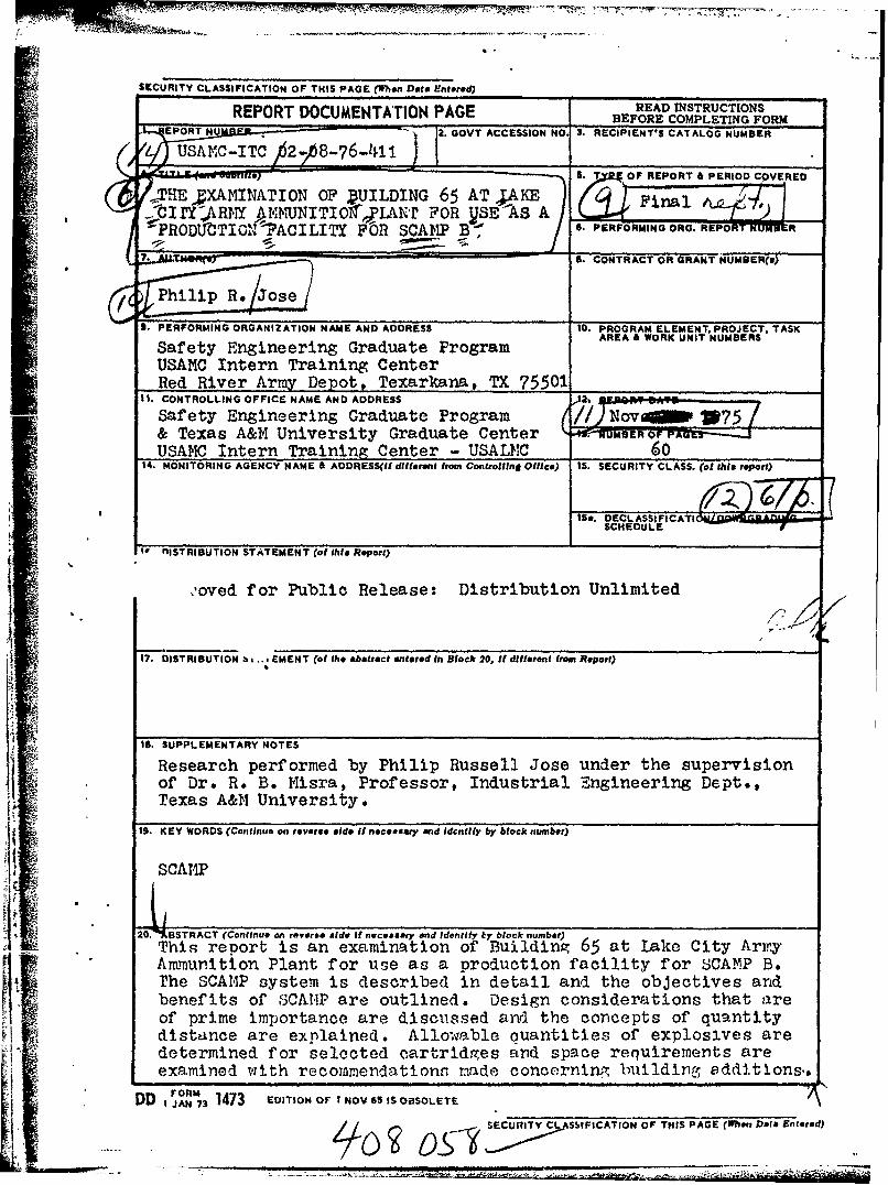
Report USAMC-ITC-02-08-76-411
THE EXAMINATION OF BUILDING 65 AT LAKE CITY ARMY AMMUNITIONPLANT FOR USE AS A PRODUCTION FACILITY FOR SCAMP B
Philip Russell JoseQSafety Engineering Graduate Program
USANC Intern Training Center,,Red River Army DepotTexarkana, Texas 75501
•--' O D CDecember 1975 D C
FEB 17 fG
Final Report A
APPROVED FOR PUBLIC RELEASE: DISTRIBUTION UNLIMITED
rrepared for
SAFETY ENGINEERING GRADUATE PROGRAM-AND TISMAS A&K UIVERS!' Y GIEVIDUAT-2 C.13NT."IUSAMC Intern Training Center - USALMC
Aed Tier Army DepoRStYGDUTCETf
4I :Texarkana, Texas '5)501
_ _ il .. . ... ... .. ... ,'2- ' . . . .. ... .. . .. ...
FOREWORD
This report was accomplished as part of the Safety
Engineering Graduate Engineering Program conducted jointly
by the USAMC Intern Training Center and Texas A&M University.
As such, the ideas, concepts and results herein presented are
those of the author and do not necessarily reflect approval
or acceptance by the Department of the Army.
This report has been reviewed and is approved for
release. For further information on this project contact
Dr. George D. C. Chiang, Intern Training Center, Red River
Army Depot, rexarkana, Texas 75501.
WONt SamW
Approved: ......................
............... ...............
Dr. GeorZ D. C. Chia'mg VDepartment of Safety Engineering
For the Comrander
inc.- L. Arncot, Di,.ctor, IT-1. -.
SECURITY CLASSIFICATION OF THIS PAGE (When D ts Entered)
REPORT DOCUMENTATION PAGE READ INSTRUCTIONSRO D MT O ABEFORE COMPLETING FORM
EPORT NU . 2. GOVT ACCESSION NO, 3. RECIPIENT'S CATALOG NUMBER
LUSAMC-ITC 2- 48-76-I1 _____________P R. uREPORT
& PERIOD CQVEREO
ATHE'XAMINATION OF DUILDING 65 AT AKE ) ' .F'aYI,7-CIrY2ART"Y A4FJNITIOf,.yL'iANr FOR SE-AS A J:f , f "" "Z. .),POtio 1' nTC ,! i %s c~rTt, ~ l : 6. PERFORMING ORO. RE-P-ORT NUM R
'-PROD1JTIC-A ?ACILITY FOR SCA11P B '.PROMN OG tRRU~
t 7 '. 1. CONTRACT OR GRANT NUMBER(SI
/ Philip Re Jose- S. PERFORMINGORGANIZATION NAME AND ADDRESS 10. PROGRAM ELEMENT. PROJECT. TASK
I Safety Engineering Graduate Program AREA& WORK UNIT NUMBERS
USAMC Intern Training CenterRed River Army Depot, Texarkana, TX 75501i',.~11 CONTROLLING OFFICE NAME AND ADDREiSS 2... . lips- :.. : ..Safety Engineering Graduate Program (// N-Novai 1075/Z
~~~& Texas A&M University Graduate Center 7W7E O A ---... USAMC Intern Training center - USAL11C 60
14. MONITORING AGENCY NAME & ADDRESS(ildifferent from Controlling Office) i5. SECURITY CLASS. (of this report)
nlISTRIBUTION STATEMENT (of this Report)
,oved for Public Release: Distribution Unlimited
17. DISTRIBUTION b s .. E MENT (of the abstract entered in Block 20, It different from Report)
IS. SUPPLEMENTARY NOTES
Research performed by Philip Russell Jose under the supervisionof Dr. R. B. M4isra, Professor, Industrial ngineering Dept.,Texas A&N University.
19. KEY WORDS (Continue on reverse aide if necessary and Identify by block number)
SCAMP
20 IIBSTRACT (Continue on reverse side if necessary end Identify iky block number)This report is an examination of Building 65 at Lake City ArmyAmmunition Plant for use as a production facility for SCAMP B.The SCAMP system is described in detail and the objectives andbenefits of SCATMP are outlined. Design considerations that areof prime importance are discuissed and the concepts of quantitydistance are explained. Allowable cuantities of explosives aredetermined for selected cartridges and space requirements areexamined with recommendations made concerning building sdditions.,
FORM
D , jAM 73 1473 EoITIOn OF NOV S IS OBSOLETEII . - SECURITY CL SSbIFICATION OF THIS PAGE (Whe Data Entered)

( -REPORT
TIM EXAMINATION OF BUILDING 65
AT LAKE CITY ARMY AMMUNITION PLANT
FOR USE AS A PRODUCTION FACILITY FOR SCAMP B
by
Philip R. Jose
Accomplished as Part of the1i AMC Safety Engineering Graduate Program
USAMC Intern Training Center
and
- iPresented in Partial Fulfillment of the Requirements of theDegree of Master of "n'nineeringI Texas A&M University
November 1975
21

ABSTRACT
Research Performed by Philip R. Jose
Under the Supervision of Dr. R. B. Misra
This report is an examination of Building 65 at Lake
City Army Ammunition Plant for use as a production facility
for SCAMP B. The SCAMP system is described in detail and
the objectives and benefits of SCAMP are outlined. Design
considerations that are of prime importance are discussed
and the concepts of quantity distance are explained.
Allowable quantities of explosives are determined for select-
ed cartridges and space requirements are examined withIirecommendations made concerning additional construction.
Conclusions are drawn and recommendations are made as to
areas of further research.
i

M -W!
ACKNOWLEDGEMENTS
I would like to extend my thanks to Dr. R. B. Misra,
my committee chairman, for his patience and assistance in
the preparation of this report. For serving as members
of my committee, I wish to thank Dr. S. B. Childs and
Dr. J. W. Foster . My gratitude is extended to Mr. John
Spencer, Mr. John Jacobi, and the personnel at Lake City
for their assistance. My thanks also, to iy wife Julie,
for her encouragement throughout the development of this
report.
During the course of this work, I was employed by the
U. S. Army as a career intern in the AMC Safety Engineering
Graduate Program. I am grateful to the U. S. Army for the
opportunity to participate in this program.
The ideas, concepts, and results herein presented
are those of the author and do not necessarily reflect
approval or acceptance by the Department of the Army.
iii

CONTENTSChapter Page
~I • INTRODUCTION.. S..•.e.e........ ...***** ... .• •550 1
II. THE SCAMP B CONCEPT...... 4
Objectives...... ............ ....... ......... 4
Companies Involved in Development........... 8
Submodule Concept........... ........ ..... .... 9
Manpower Requirements........................o 17
III. DESIGN CONSIDERATIONS FOR EXPLOSIVESFACILITIES AS RELATED TO SCAMP B.. ....... 21
Special Considerations forInitiating Explosives.•.•.•.•.••••............ 21
The Class System for Hazardous Explosives.... 22
Quantity Distance Requirements............... 23
Barricading.... .*....*...*....*......... 25
IV. PROPOSALS OF PRODUCTION RATES ANDBUILDING LAYOUT CONSIDERATIONS... .............. 27
Introduction.. ...... .... . .000.... 27
Allowable Quantities ofj ~ Explosives in Each Submodule................. 28
Analysis of Space Requirements............... 37
Additional ConsiderationsConcerning Redesign.......................... 45
V. CONCLUSIONS AND RECO,1,iNDTIONS.......... ...... 49
BIBLIOGRAPHY .,. . ••............ • • . .... o...............
iv

FIGURES
Figure Page
2.1 ROTARY TURREr CONCEPT ....... ...... ............. 7
2.2 PROCESS FLOW BLOCK DIAGRAMFOR SCAM'P MODULE B.................... 10
2.3 CASE, CARTRIDGE, 20mm, I103A1.................. 11
2.4 FUZE-TO-PROJECrILE ASSEI-LY.................... 17
4.1 STRAIGHT LINE DISTANCES FOR BUILDING 65........ 36
4.2 PLAN VIEW OF BUILDING 65....................... 38
4.3 BASIC LAYOUT OF BUILDING 65................... 43
4.4 FLOW DIAGRAM FOR MATERIAL HANDLING........... .. 44
4.5 BUILDING 65 WITH PROPOSED ADDITION............. 46
4.6 FLOOR PLANS OF PROPOSEDADDITION TO BUILDING 65........................ 47
It V
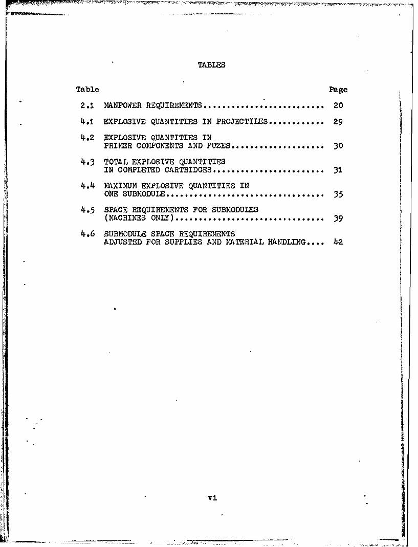
TABLES
Table Page
2.1 MNPOWER REQUIREmENTS.......................... 20
4.1 EXPLOSIVE QUANTITIES IN PROJECTILES............ 29
4.2 EXPLOSIVE QUANTITIES INPRIMER COMPONENTS AND FUZES................... 30
4.3 TOTAL EXPLOSIVE QUANTITIESIN COMPLETED CARTRIDGES........................ 31
4.4 MAXIMUM EXPLOSIVE QUANTITIES INONE SUBMODULE .......... o ...... . .... 35
4.5 SPACE REQUIREMENTS FOR SUBNODULES(MACHINES ONLY) ................................ 39
4.6 SUBMODULE SPACE REQUIREMENTSADJUSTED FOR SUPPLIES AND MATERIAL HANDLING.... 42
vi

R
CHAPTER I
INTRODUCTION
The Vietnam conflict brought to light the need for new
methods of producing ammunition. The heavy use of rapid
firing air to ground weaponry bore an unending demand on
our production for 20mm and 30mm small caliber ammunition.These new sophisticated weapons were capable of firing as
many as 6,000 rounds per minute, and the outdated machinery
being used to produce ammunition was not able to meet such
rigorous demands. In fact, if it were not for our large
stockpiles of ammunition that were available during the
Vietnam War, a serious shortage would have occurred.
With the realization that a serious gap could occur
if the need for prolonged supply would again arise, several
studies were initiated to determine methods and means of
improving and modernizing cartridge production. The initial
search for technology to modernize smal) caliber ammunition Iproduction was initiated at Frankford Arsenal in mid 1968.
The program was labled SCPMP - an acronym for "Small
Caliber Ammunition Modernization Program".
SCAMP is divided by cartrid.e size into two areas.
The first is module A, designed to produce 5.56 mm and
7.62 mm ammunition and second module B, designed to produce
•50 caliber, 20 mm and 30 mm ammunition.
LL4
2
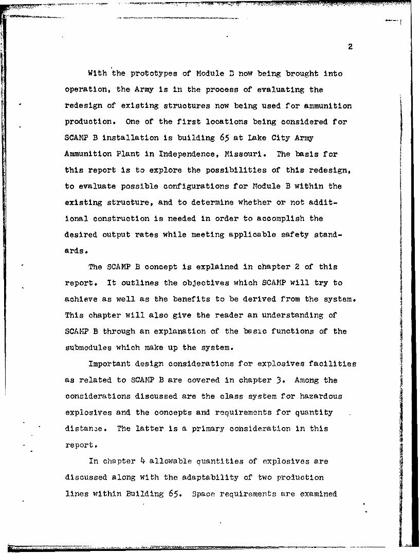
With the prototypes of Module B now being brought into
operation, the Army is in the process of evaluating the
redesign of existing structures now being used for ammunition
production. One of the first locations being considered for
SCAMP B installation is building 65 at Lake City Army
Ammunition Plant in Independence, Missouri. The basis for
this report is to explore the possibilities of this redesign,
to evaluate possible configurations for Module B within the
existing structure, and to determine whether or not addit-
ional construction is needed in order to accomplish the
desired output rates while meeting applicable safety stand-
ards.
The SCAMP B concept is explained in chapter 2 of this
report. It outlines the objectives which SCAMP will try to
achieve as well as the benefits to be derived from the system.
This chapter will also give the reader an understanding of
SCAMP B through an explanation of the basic functions of the
submodules which make up the system.
Important design considerations for explosives facilities
as related to SCAMP B are covered in chapter 3. Among the Iconsiderations discussed are the class system for hazardous
explosives and the concepts and requirements for quantity
distance. The latter is a primary consideration in this
report.
In chspter 4 allowable ouantities of explosives are
discussed along with the adaptability of two production
lines within Building 65. Space requirements are examined
i • • i i g I i i "! " ' i] " " " "r r " -" -- ... ... ...

3
with respect to submodule placement and suggestions are made
concerning additions to the building.
In chapter 5 recommendations are made and conclusions
are drawn on the author's investigation of the system and the
analysis contained within this report. Limitations of the
analysis are covered and recommendations are made as to
areas needing further work.
4

CHAPTER II
THE SCAMP B CONCEPT
OBJECTIVES
In order to establish a means of evaluating various
concepts for SCAMP, a series of objectives to be achieved
and benefits to be derived were established. They are as
follows : (14)
1. To achieve a substantial reduction in inventory
on-hand and requirements for storage space through
decreased production lead time and increased rates.
2. To reduce cost of manufacturing by reducing man-
W hours iequired. Reducing maintenance cost, improv-
ing tool life and increasing machine efficiency.
3. To improve quality of product and reduce scrap
through better controls, better processes and
continuous inspections.
4. To reduce firing test costs, time, quantities
fired, and inventory held pending completion
of tests by use of autonated on-line testing
and improved quality of product.
* Numbers in brackets refer to numbered references in the
I ,bibliography.
I

5
Ir 5. To improve ability to meet changing mobilization
and peacetime requirements through versatility,
i.e., conversion from one to another caliber;
ability to handle a variety of metals; conversion
within defined limits to manufacturing new
generation cartridges; and most important of all,
replacement of an obsolete base.
6. To improve environmental conditions at the work-
site and in the community through better pollution
control, application of human engineering, and
reduction in working hazards.
In order to achieve these objectives the following operation-
al criteria were established:
1. Minimum design operating speed of 600 rounds
per minute.
2. Transportation of components through all manufactur-
ing and packing operations in continuous motion in a
captive work oriented position.
3. Automation of in-process inspection and identificat-
ion of defects as early as possible with rejection
of defective materials.
4. Incorporation in design features nec' ssary for a
successful preventative maintenance program.
5. Operation must be economical when running at less
KI than design speed.
q:

6
6. Provision for acquisition of quality control and
production management data through logic devices
and computers.
7. Incorporation of the modular concept for failure-
prone components and perishable tooling, allowing
for quick replacement of these components by minimum
skilled operating personnel.
After a long careful study of the available methods of
conversion, a new system utilizing rotary turrets similar
to that found in the pharmaceutical industry was used as
the basis for modernization. A somewhat simplified example
of this cnncept is shown in figure 2.1
Although the design production rate is 600 pieces per
minute (ppm), a more realistic rate during daily operation
will be approximately 300 ppm. However, even this slowerrate will exceed by more than 4 times the current production
rate of 40 to 70 ppm. Production is now based on a batch
method of material handling, which is slow and Inefficient.
The SCAMP system utilizing a continuous production.flow
technique will afford greater efficiency at higher product-
ion rates and at lower costs primarily due to a drastic
reduction in labor requirements. (15)
•II

TI
0. 0
4F4
0E
w 4
E-4Z
o'
C-4 0 r-4
to to
4W'
HH -r
1k 4 4
0) Cd
A, -4
*1r.4
-7777 C

8
COMPANIES INVOLVED IN DEVELOPMENT
Through my reading and discussion with personnel
related with SCAMP, I have found that it is generally
accepted that the operational responsibility for SCAMP
Module B will be assigned to Remington Arms Company, Inc.
at Lake City. Their responsibilities should include
planning, preparation of engineering proposals, and execution
of engineering proposals approved by the Government for plant
expansion projects, short range improvement projects, and
plant upgrading projects.
The first phase development on the automatic cartridge
assembly prototype will be handled by the Gulf and Western
Corporation. This includes the design and fabrication of
the basic machinery necessary to perform assembly operations
at the deqign rate of 600 ppm. H. P. White Laboratories has
the first phase of a prototype development contract for HEI,
High Explosive Incendiary, charging which includes the
design and fabrication of the basic machinery. The Link Pack
contract was awarded to the Design and Development Company
for a prototype M14 type linked cartridge and M548 container
system. Ameron Corporation is working with the steel case
development. An extensive preliminary Facility Systems
Analysis for Module B has been performed by Paul R. Zirkel
hi of Honeywell Incorporated. An ammunition production base
restructure study for SCAMP was performed in 1973 at
Frankford Arsenal.K

9
SUBMODULE CONCEPT
In order to achieve the objectives listed, a concept
Iutilizing submodules for each of the main phases of product-
ion was established. The submodule concept has proven to
be an effective method of production for Module A and will
be applied to P odule B.
-A submodule is defined as the equipment necessary in
the production of major components, such as the cartridge
case. Module B is an integrated series of submodules with
a common production rate and capacity, coupled together by
a transfer and quality control system. In all there are
thirteen submodules which make up the entire system for
Module B. The following description of each of the submodules
indicates what submodules are involved. A process flow
4 diagram, Figure 2.2, is used to illustrate the material and
information flow between each submodule. (15)
CASE 14ANUFACTURE - This submodule will manufacture
the M103AI steel cartridge as illustrated in Figure
2.3. The case will be made through a number of
draw out processes starting with flat discs that
will be cut from sheet stock steel. A modified
rotary system using a "Sash-Togple" concept will
be considered to develop the larger forces requiredil for forming the steel case. A design requirement
of 600 ppm will be used for this submodule.

44
FE4 H
0 co
P4 jP4CI
H zo
r44
A4
P44
V
04
COO
E- to t) -
L00K lK F\El

C141
- F
H 04~vW9T9
0
'-43
443
E-.-
i0
I • or 4

12
PRIMER MANUFACTURE - This submodule is designed for
manufacturing percussion and electric primers at
varying rates up to 1200 ppm. The submodules are
compact, self contained and fully automated manhine
systems incorporating a 100 percent failsafe
inspection system for all critical parameters. The
equipment developed for primer manufacture will be
universal in nature such that conversion from one
primer requirement to another will be-acomplished
through the use of interchangeable tooling and
feed systems.
PRIMER INSERT - This submodule will be designed to
accommodate electric or percussion primers as
required, along with various cartridge sizes. The
process will be accomplished at a design rate of*
600 ppm and will incorporate a 100 percent fail-
safe inspection system to insure that all critical
parameters comply with appropriate specifications.
The primed cases will then be discharged to a trans-
fer system for delivery to the load and assemble
submodule.
LOAD and ASSEMBLE - This is a self-contained,
universal and fully autonated submodule capable of
loading and assembling cartridges at variable rates
up to 600 ppm. Remote controls are included to

13 .
provide maximum personnel safety and minimize thenumber of operating personnel. The machine receives
primed cases and projectiles in a captive and
oriented manner, receives and dispenses propellantand performs other operations leading to discharge
of assembled and loaded cartridges to a transfer
system for delivery to the packing submodule. The
load and assemble submodule also includes a 100
percent fail-safe inspection system.
TRACER CHARGING - This submodule receives andcharges at a rate of 600 ppm. The machine has
devices for accepting and monitoring the applicable
trace mixes and provides for interchangeable
tooling and feed systems for conversion to different
projectile sizes. Remote control facilities are
included to insure maximum personnel safety. The
trace2 eharged projectiles discharge to a transfer
system for delivery to the HE/HEI, High Explosive/
High Explosive Icendiary, charge submodule.
HE/HEI CHARGING - Producing at the rate of 600 ppm.
this self contained, fully automated submodule will
be remotely controlled to reduce operating personnel
and insure safety. A 100 peruenrik. fail-safe
inspection system will monitor all critical para-
meters to insure compliance with quality standards.
-~ - ____

14
The HE/HEI charged projectiles are discharged to
a transfer system for delivery to the fuze-to-
projectile assembly submodule.
DETONATOR CHARGE and ASSEMBLY - The explosive
material used in charging at this submodule is
lead azide, and RDX (Cyclonite) and is extremely
hazardous. Therefore remote control and other
devices will be used to insure full and complete
protection of all operating personnel. Fail-safe
inspection will also be incorporated into this
submodule.
BOOSTER CHARGE ASSEMBLY - This submodule will
charge and assemble fuze boosters at a rate of
600 ppm. It will incorporate remote control for
the protection of operating personnel and fail-
safe inspection will take place to verify all
critical parameters. Charged and assembled fuze
booster holders will then be delivered to the
fuze assembly submodule.
FUZE ASSEMBLY- This submodule assembles charged
rotors and booster holders with fuze assembly of
600 ppm, and is fully autonated and self contained.
From here the fuze assemblies are transfered to
the fuze-to-projectile assembly submodule.

15
• FUZE-TO-PROJECTILE ASSEMBLY - This machine accepts
and orients charged fuzes and applies the proper
thread sealants. It is a self contained and fully
automated submodule capable of assembling charged
point detonating fuzes to HE/HEI charged projectile
bodies at rates up to 600 ppm. The equipment uses
100 percent fail-safe inspection and remote control
facilities are provided to insure personnel safety.
The assembled fuze and charged projectile bodies
are discharged to a transfer system for delivery
to the load and assemble submodule.
PACKAGING - This submodule accepts assembled cart-
ridges and processes the components in a captive
oriented manner from linking through palletizing-
and banding operations. It links at variable rates
"up to 600 ppm and assembles cartridges into pre-
scribed belt lengths with predetermined ratios of
HE/HEI and tracer cartridges and packages the
. belted cartridges in M548 containers.
BALLISTIC ACCEPTANCE TESTING - The ballistic accept-[ ance will perform all those tests now done by the
*! present range but in an automatic fashion employing
a computer. The automatic equipment -v1ll 1reduce
the time, between actual testing and the reporting
of the test results. Phe time reduction will avoid
- ,problems of storage of ammunition to await test

16
-results and will also permit a faster process
correction to adjust the propellant charge in the
load and assemble module should the ammunition
fail the prescribed tests.
PROCESS QUALITY CONTROL SYSTEM (PQCS) - This master
quality assurance computer will monitor the entire
production process continuously analyzing the
inspection data. It will predict potential trouble
by determining if any adverse trends are developing
and give indications of preventive maintenance.
This system will greatly decrease the amount of
down time and improve overall production efficiency.
The use of the computers storage bank will enable
management to make accurate decisions when sched~il-
ing production, maintaining inventory control and
"ordering raw materials.
To better understand the workings of the submodule
concept, a representative example of how one of the sub-
modules might be laid out is shown in figure 2.4 . The
submodule represented is the Fuzt -to-Projectile Assembly.
As illustrated in figure 2.4, the main components of
the submodule are located within a barricaded area with no
personnel present within the barricade. The direction of
material is indicated by arrows. The projectiles are brought
in from the HE/HEI charging area and accumulated in an
automatic feeder. The first step in this subm: odule is the
tl"

j7= ----17
II- N CI)
H 43
N W 4 04 A
OO 3a 0 ) 0 0
to 0. A )S4 ~to3 I0a),.4 H 4H 0
I,,, 4.0 0~
0O Or 0 to4) 'rHs 43 toa 0
1- 0 H 0
.p 0.ro. 4o 0 E-4
LLO ~ 44 ~

-o -" ' - 1 , 1- -3 '7
18
application of a sealant to the threads and a sealant check.
Once this is accomplished the oriented fuzes are fed in and
assembled to the projectiles. Height and-gap openings
between the fuze and the projectile are then checked. A
continuous inspection is under way during all phases of
assembly and reject stations gather the out of spec cartridg-
es. A final inspection is made outside the barricaded area
for excessive sealant, loose fuze covers, and orientation
of the fuze to the projectile. Closed circuit television
also monitors the operations and viewing screens are provid-
ed for each of the operators. The barricaded control room
contains the main operation console with monitoring and
process controls.
MANPOWER REQUIREMENTS
The original manpower requirements were developed on
the basis of two modules operating on a 2-5-8 shift basis,
j. that is two shifts operating eight hours per day five days
fi per week. However recent reports suggest the strong
possibility of a six day work week instead of five.
The total number of personnel needed to run the
.1* complete two module system is projected to be 382. Personnel
required for the direct labor of operating the machines will
number 154, an additional 58 supporting personnel will be
necessary with 170 indirectly related personnel rounding out
the 382 figure. The automatic component transfer and
material handling systems will not need constant supervision,
° !

19
Any attention to be given these systems will be minor,
other than periodic maintenance, which can easily be handled
by the personnel operating the submodules. It should be noted
that the ballistic testing and Process Quality Control
System personnel will handle both production lines therefore
reducing manpower requirements. Table 2.1 shows a breakdown
of the labor force as related to the submodules.
!!'.1

20
TABLE 2.1
MANPOWER REQUIREMENTS
SUBMODULE MEN PER SUBMODULE
Case Manufacture 7
Primer Insert 8
Load and Assemble 3
HE/HEI Charging 5
Fuze to Projectile Assembly 3
Packaging 13
Detonator Charge and Assembly 7
Tracer Charging 2
Fuze Assembly I
Primer Manufacture 21
Booster Charge and Assembly 5
Component Transfer/Material Handling 0
Ballistics Testing 3
PQSC I
Total 79
Manufacturing Technology Directorate Report, November1973, p. 4.2
Li

CHAPTER III
DESIGN CONSIDERATIONS FOR -XPLOSIVES
FACILITIES AS RELATED TO SCAMP B
SPECIAL CONSIDERATIONS FOR INITIATING EXPLOSIVES
The initiating explosives lead azide and RDX (cyclonite)
will be present in bulk quantities in the detonator charge
and assembly submodule. Special precautions are necessary
" due to the sensitivity of these explosives. They are sensit-
ive to friction, heat and impact, and will detonate without
burning when involved in a fire.
Whenever these materials are worked with or stored,
' the quantities should be limited to the smallest practical
amount. For long periods of storage, they should be kept
wet with water or a water-alcohol mixture. A wet type dust
collection system should be used in areas where initiating
explosives are worked with. The sensitivity of these mater-
A ials is increased by many foreign materials and it is therefore
mandatory that a high degree of cleanliness be maintained.
-All rooms in which these explosives are to be handled must
A ,be designed to be completely free from static electricity
or flooring rust be macle of condcuctive rnterial. It would
be desirable for both of these conditions to be vet in order
21
2.1 -

22
to achieve the highest degree of safety. The walls of the
rooms should be constructed of a waterproof material with a
hard gloss finish and should be washed often with a neutral-
izing solution to prevent explosive dust buildup on the
surface.
THE CLASS SYSTEM FOR HAZARDOUS EXPLOSIVES
The Army has divided hazardous explosive material into
seven classes, severity of hazard increasing as numbers
increase. Class I is considered to be ammunition that
presents a fire hazard but no blast or fragmentation hazard
beyond the fire hazard clearance specified for high-risk
materials. Class 2 explosives are defined to be propellants
j and single-base, single-perforated rifle propellant. Class
3 materials are fuzes and artillery primers, and should be
handled in such a manner as not to strike against each other.
In the event of an explosion involving Class 3 material the
fragments generated are considered to be light and would not
endanger areas beyond 300 feet. Classes 4 and 5 are consid-
ered to be ammunition that presents little threat of fire
unless deterioration has occurred. If a single item in a
stack of Class 6 ammunition deton..tes, or if the stack is
exposed to fire, the entire stack of explosives will detonate
as a mass. For this reason Class 6 material should not be
stored In large quantities without taking precautions to
prevent propagation to nearby stacks of explosives. Class 7
items are hazardous explosives of the highest order and if

23
involved in a fire will mass detonate.
QUANTITY DISTANCE REQUIREMENTS
Quantity distance specifications refer to the limiting
minimum distances allowable between any two areas, such as
buildings, based on the quantity of explosives these areas
contain.(10) The maximum amount of explosives that may be
located in any one area is regulated by the distance between
the hazard and other areas that could be damaged as a xesult
of an explosion of the hazardous material. Two other factors
that could either shorten or lengthen this distance are the
type of structure, construction, occupancy, etc. and whether
or not barricading, either natural or man-made, exists.
Tables in Chapter 17 of AMCR 385-100 are available for
determining the minimum allowable distances between explosive
hazards and specified building and area types. It should be
emphasized that the distances given in the tables are the
minimum required for safe operation. The distances should
never be shorter than those listed and if at all possible
greater when space permits.
Quantity distance requirements can be expected to
provide protection to buildings so that propagation of
explosions due to blast effects are minimized but it does
*not provide protection against explosive propagation due tohazardous fragments. A hazardous fragment being defined as
one having an impact energy of 58 foot-pounds or more.

24
Inhabited building distance as defined in AMCR 385-100
is the minimum permissible distance between an inhabited
building and an ammunition or explosives location. An
inhabited building being defined as; "A building or structurei)
other than operating buildings, magazines and auxiliary
buildings occupied in whole or in part as a habitation for
human beings, or where people are accustomed to assemble,
both within and outside of Government establishments. land
outside of the boundaries of AMC establishments shall be
considered as possible sites for inhabited buildings."
Because of the possible harm to human life in the event of
an explosion, nearby inhabited buildings are of primary
concern when designing an explosives facility. Inhabited
building distances are also used between adjacent operating
lines, explosives locations and other exposures within an
establishkent.
Public railway quantity distances for class 7 explosives
are calculated as 60 percent of the inhabited building
distance and can be found in table 7-11 of AMCR 385-100 along
with inhabited building quantity distances. The reasons for
the allowable decrease in distance Is the greater resistance
of railroad cars to blast effects as compared with buildings,
and that the percentage of time the cars are exposed to the
- hazard is considerably less than buildings which are station-
ary and subject to constant risk. ?or materials other than
class 7, the required quantity distances for public railways
are equal to the inhabited building distances.
25
Public highway quantity distances are identical to public
railway distances.
Intraline distance is the minimum permitted distance
between any two buildings within one operating line.(17)
rhis distance is also used for certain areas and buildings
even though actual line operations are not involved. The
only exceptions are service facilities which serve a
particular operating explosives facility. In this instance
the intraline distance requirement does not have to be met
but may never be less than 100 feet from the building which
it serves. However it must comply with intraline distance
requirements for all other explosives facilities in the area.
The maximum quantity of explosives permissible in each
existing building is defined by DOD 4145.26M: "Separation
distances for determining the maximum allowable quantity of
explosiveo shall be measured from the outside of tbe nearest
wall, side or back of a structure, controlling room or
controlling cubicle to the outside of the nearest wall, side
or back of another structure, room or cubicle."
BARRICADING
MI Properly constructed artificial or natural barricades
are an effective method of protecting nearby structures
from damage due to explosion. They also are an effective
means of reducing the allowable ouantity distance require-
ments for buildings housing eplosives. However, such
barricades are generally considered to be ineffective for
26
reducing distances required for fire hazard materials such
as class 2 propellant and missile producing ammunition such
as in classes 3, 4, 5 and 6. Barricading is considered most
effective for items having mass detonating characteristics.
A barricade is considered effective when properly
constructed and when a line drawn from the top of any side-
wall of the building containing the explosives to all the
parts of the location to be protected will pass through the
intervening barricade. (5) The barricade must be separated
from each of the buildings and may be located adjacent to
either, although it is preferable to locate it near the
building that is being protected. The toe of the barricade
must be no further than 40 feet from the structure and is
recommended to be as near as possible to the minimum
distance of 4 feet.
R
j -

CHAPTER IV
PROPOSALS OF PRODUCTION RATES
AND
BUILDING LAYOUT CONSIDERATIONS
INTRODUCTION
Building 65 at Lake City is being considered for housing
two production lines consisting of the following submodules;
Tracer Charging, HE/HEI Charging, Fuze-To-Projectile Assemble,
and Link Packing. The System Integration Report for Prepara-
lion/layout Planinx for Module B states that "It is the
objective of the contractor to direct all reasonable effort
to adapt the submodules to the existing building configura-
tion." Therefore the possibility of operating the required
submodules within the existing structure will be explored.
In this chapter allowable quantities of explosives for
four cartridge-types will be examined and recommendations
will be made as to whether or not the proposed production
methods will or will not violate existing quantity distance
requirements. Space requirements will also be looked at in
order to determine the inost efficient means of arranging the
submodules. In addition, some ideas concerning new con-
struction and placement of expanded facilities within
building 65 will be discussed.
27

28
ALLOWABLE QUANTITIES OF EXPLOSIVES IN EACH SUBMODULE
Pour types of cartridges were considered as representi-
tive of the majority of the ammunition to be produced in
Building 65. They were examined for the purpose of determin-
ing whether or not they could be produced at the design
production rates and meet the requirements for quantity
distance. The designations of the cartridges considered are
listed in Table 4.1 along with the grains of explosives in
each projectile, the number of projectiles that can be
charged with one pound of explosives, and the total pounds of
explosives that are in 1000 projectiles of that particular
piece of ammunition.
Table 4.2 lists the types of primer components and fuzes
that are used in the four cartridges considered. Listings
are given in the same manner as in Table 4.1, grains each,
pieces per pound, and pounds per 1000 pieces.
The information from Tables 4.1 and 4.2 is used in
making up a comprehensive Table, 4.3, that gives in addition
to the explosives that are present in the form of projectile
charges, primers, and fuzes, the pounds of explosives present
in 1000 completed rounds of the designated cartridge. The
additional explosive material that makes up the total amount
in the completed round is in the shell casing in the form of
propellant. This is also listed in the table. For the
purpose of mrximizinrg the safety factor the electric primer

29
TABLE 4.1
EXPLOSIVE QUANITIIES IN PROJECTILES
GRAINS PIECES POUNDSCOMPONENTS & OPERATIONS EACH PER POUND PER 1000
M56A3 HEI
1st & 2nd Charge 150.00 46.6667 21.2493rd Charge 26.00 269.2308 3.714Total 176.00 315.8975 25.143
M53 APIIst Charge (IM 136) 25.00 280.0000 3.5712nd Charge (IM 68) 30.00 233.3333 4.2863rd Charge (IM 68) 21.00 333.3333 3.000Total 76.00 846.6666 10.857
M246 HEIT-SDCharge Tracer Cavity:Ist Charge (Trace Mix LC-5B)16.o0 437 5000 2.2862nd Charge (Trace Mix LC-5B)11.00 636:3636 1.5713rd Charge (Ign. Mix LC-Y2) 5.00 1400.0000 .7144th Charger (Ign. Mix 1-136) 5.00 1400.0000 .714Charge HEI Cavity:WC-870 12.00 583.3333 1.714LCA#1 50.00 140.0000 7.143LCA#1 34.00 205.8824 4.857LCA#1 34.O0 205.8824 4.857Total 167.00 5008.9617 23.856
M242 HEITCharge Tracer Cavity:Ist Charge (Trace Mix R-403)12.00 583.3333 1,7142 2nd Charge (Trace Mix R-403)15.00 466.6667 2.1433rd Charge (Sub I Mix 1-280) 4.00 1750.0000 .5714th Charge (Ign. Mix 1-136) 5.00 1400.0000 .714Chsmyp. UI Cnvitv:
1st Charge iAC Y1 75.00 93.3333 10.7142nd Charge IAC #1 37.50 186.6667 5.3753rd Chr~rge IAC I 311.00 205.8824 4.P57 A
Total 182.5 4685.8824 26.070

30
TABLE 4.2
EXPLOSIVE QUANTITIESIN
PRIMER COMPONENTS AND FUZES
PRIMER COMPONENTS
GRAINS PIECES POUNDSCOMPONENTS & OPERATIONS EACH _ PER POUND PER 1000
Electric (M52A3BI) 2.58 2456.1404 .047Pellet
Percussion (36AIE1) 2.20 3181.8182 .314Pellet
FUZE
GRAINS PIECES POUNDSCOMPOITNETS & OPERATIONS- EACH PER POUND PER 1000
Booster
1st Charge 7.78 899.7429 1.111
2nd Charge 6.80 1029.4118 .971
3rd Charge 7.02 997.1510 1.003
Total 21.60 2926.3057 3.085
Det6pnator ?57E1 (Al. Cup)
1st Charge .386 18134.7150 .005
2nd & 3rd Charge 1.997 17259.1753 .285
Total 2.383. 35393.8903 .290

031.
Co
%D N D
r4r
%00V-4 4
0- 0 040
V U~') 0 '% %0
H C)
E-44
H
H HCY-'l
p C~*

32
was considered to be used in all cases,as the explosive
quantity present was slightly higher than that of the
percussion primer.
In determining the amount of explosives allowable in
each submodule,i.e.;the maximum pieces of ammunition in any
one area, the actual numbers shall be dependent upon the
distances that exist between Building 65 and surrounding
structures. It is assumed that each submodule will be
designed so that an explosion in any one area will not
propagate to nearby submodules. This will be accomplished
by effective barrier design, proper placement and spacing
of the submodules within the building and by keeping the
quantities of explosives in a single submodule within
acceptable recommended limits.
When determining the allowable production rates and
accumulation of explosives within a submodule the governing
safety manual AMCR 385-100 states in paragraph 17-8a on
page 17-4 that "When the total quantity is so subdivided
that an incident involving any one of the subdivisions will
not produce simultaneous initiation of others, the net weight
of the mass-detonating explosives in the largest subdivision
shall apply." Therefore the existing quantity distances will
determine the r-3ximum amount of explosives allowable in one
submodule and not the total quantity for the entire building.
In so much as the majority of the explosives that will
be used in Building 65 will be Class 7, Mr. John Jacobi,
Chief Engineer at Lake City has suggested that for the

33
purpose of this report, all explosives to be used may be
considered Class 7. This will provide yet another safety
factor in that the quantity distances calculated will be of
the highest order and the allowable quantities of explosives
determined will be considered conservative due to the fact
that some of the explosives will actually be of a lower class.
This suggestion will be followed and is considered by the
author to be a reasonable approach, as similar suggestions
are made in applicable Army documents.
According to lake City Engineers the production methods
that will initially be used will not include the proposed
conveyer type transfer system for movement of cartridges
between submodules. Instead they will use a buggy system
similar to that presently in operation in Module A. The
buggies to be used will hold approximately 1,200 rounds of
0mm or 30mm ammunition. The present plan is to make 20
minute production runs, allowing the products of each sub-
module to be collected in the buggy and remain in the sub-
module until the end of the run. At that time the loaded
buggies will be brought through the center corridor to the
submodule which is next in the production line.
Regulations state that a supply of material capable
of maintaining production for 1 hour or 3 twenty-minute runs
must be Availabl) at all times. rherefore the bays contain-
ing lazardous supply rraterials will have these neces.ary
amounts in them, and will be the areas of the highest
concentration of explosives.

34
During production the loaded buggies will be moved
directly to the next submodule in the production line for
continued processing. However, at some stage a backup may
occur and the empty bays within the loading wing will most
likely be used for storing the excess marerial. This will
be considered acceptable as long as the quantities stored
do not exceed the recommended maximums for one bay.
Table 4.4 shows the maximum amount of explosives that
will be present in any submodule for the four cartridge types
being considered. Figure 4.1 shows the distances to nearby
roads, railroads, and buildings which are to be considered
when determining allowable quantities of explosives in
Building 65. As can be seen the shortest inhabited building
distance is 670 feet. This is building 143, a testing
laboratory. The two public highway/railway distances to be
considered- are 4,700 feet and 5,450 feet.
The maximum amount of explosives from Table 4.4, 3272.4
pounds, is considered when determining the minimum allowable
quantity distance. Checking Table 17-11 in AMCR 385-100,
the Class 7 distances for inhabited buildings, it is found
that for explosive quantities between 3,000 and 4,000 pounds
the minimum distance is 635 feot. For the same quantities
of explosives Table 17-11 also shows a minimum distance of
380 feet for public highways and railways. A comparison of
these values with the ones presented in Figure 4.1 shows no
violation will occur for the quantities of explosives
calculated.

35
r-'4 t4 ~0 \0 O C 4
to (
r
-4 p
: 0H04 H 0H0t

36
Co5
C.)-
0 C
0
04 H
rxz
4p
0 F
00
:4

37
It should be noted that only the Load and Assemble and
Packing submodules will have completed rounds in them.
Therefore the other submodules within the building will not
have the maximum amounts of explosives present as listed in
Table 4.4 • This provides for yet another margin of safety.
When ammunition is packed and ready for shipment it is
considered Class 2 and therefore larger amounts af ammunition
could be allowed to accumulate at the end of the packaging
submodule. In fact, for the quantity distances present
around Building 65 up to 500,000 pounds of Class 2 explosives
may be present according to Table 17-5 in A14CR 385-100
While it is permissible for large quantities of Class 2
explosives to accumulate it is recommended that actual
quantities be held to as low a level as possible by use of
an effective trucking schedule which would remove completed
rounds and transfer them to the appropriate storage facilit-
jesei
ANALYSIS OF SPACE REQUIREDONTS
Building 65 is presently being used for production of
small caliber ammunition. The building therefore already
has a number of bays in the present loading wing. These
will be used for containment of the submodule equipment for
all but the packaging operations.
The overall dimensions of Building 65 are given on a
plan view drawing, i-Pigure 4.2 . The gross envelop dimensions
and the required square footage for each submodule is given

1 38
.30
-0I-- • ....
- FIGUflU 4.2
SPLAN VIEW OF BUILDING 65
I * All dimensions drawn to the nearest foot
F'

39
TABLE 4 .5
SPACE REQUIREMENTS FOR SUBMODULES (MACHINES ONLY)
GROSS ENVELOP
SUBMODULE DIMENSIONS FLOOR SPACE (ft2 )
W X LXH
HE/HEI CHARGING 8'X28'X10' 224
LOAD & ASSEMBLE 9'X25'X8t (Assemble)3 15
9'X10'X6' (Inspect) i
TRACER CHARGING 14'X30 'XlO 420
FUZE-TO-PROJ. ASSY. 7IX16'X8' (Assemble) 2'182
i 7'Xl0'X8' (Inspect)
1 LINK PACKING 30'X70'XlO' 2100
D
• Does not Include palletizing and manual rework area

A 7r -'7.
40
in Table 4.5 • This is the area necessary for the machinery
only and was obtained from data found in the System Integra-
tion Report for Preparation/Layout Planning for Nodule B,
dated July 15, 1975.
In addition to the square footage needed in each sub-
module for the machinery, areas must be available for storage
of inert and hazardous materials and components. There must
also be space provided for storage of spare parts for quick
repair, for example quick change tool sets. This space
should be large enough to accomodate quantities of material
that would be received by trailer trucks in normal truckloads.
Sufficient aisle space should also be provided for efficient
material handling. It is recommended that 20 ft2 or 10 per
cent of the submodule area, whichever larger, be allowed for
submodule supplies and 40 ft2 or .25 per cent of the submodule
area, whichever larger, be allowed for spare tooling and
presetting fixtures. Table 4.6 shows the adjusted areasnecessary to meet the requirements.
Operator stations will be designed in such a manner as
to maximize safety for all personnel and to remain compatible
with the system. The stations will provide noise attenuation,
vibration isolation and complete environmental control,
* tempersture, hu.nidity, etc. Double ianefl led glass walls
have been suggested as a possible means peritor sauper-
vision for respective submodules. Howvc for improved
safety it is recommended that the operator stations be
eguipped with closed circuit television nonitoring which

41
would enable them to be completely barricaded form all explo-
sive hazards during operation, a method similar to that
described in Chapter 2 of this report.
The existing configuration of Building 65 lends itself
ideally to the incorporation of two production lines. It is
recommended that the entire loading wing be used to spread
out the charge and assembly operations. This can be accomp-
lished by utilizing the existing 30 bays within the wing.
Each bay has identical dimensions, 19 feet by 34 feet, or
646 square feet of useable floor space. Refering to Table
4.6, Submodule Space Requirements, it can be seen that each
of the four submodules to be located in the wing will easily
fit within the existing bays. This is due to the fact that
all required areas are below the 646 square feet available.
It is also recommended that the submodules be separated by
empty bays~when possible.
Two production lines will be operated parallel to each
other seperated by a 13 foot wide corridor. The bays in
each production line containing hazardous materials and
operations should be opposite empty bays or bays containing
inert storage. This will minimize the chances of explosive
propagation in the event of an accident.
Mr. Paul R. Zirkel in his Facility Systems Analysis
of Module B has suggested. a layout which incorporates all
of the above mentioned design criteria. Figure 4.3 indicates
the proposed usage of existing Vays. The labeled areas on
the plan view drawings are meanrt to show suggested locations

42
I TABLE 4.6
i jSUBMODULE SPACE REQUIREMENTS
ADJUSTED FOR SUPPLIES AND MATERIAL HANDLING
MACHINE TOTALSUB,_ODULE REQIREMENT (ft 2 ) REQUIREMENT (ft 2 )
HE/HEI CHARGING 224 302.4
LOAD & ASSEMBLE 315 425.25
TRACER CHARGING 420 576
FUZE-TO-PROJ. ASSY. 182 245.7
LINK PACKING 2100 2835
Does not include palletizing and manual rework area

43
H o0 H CO
61 0
0oC 0 EH oH H H 0
~c to 0 ) HC
-'- I 0 / 0 t-:-HP4 H4 co~
V CO
H 0o
SU F-4 0 M
-| ,
iCi o ~ C
N C
-L i

44
zK
H HCI
P4 W4
o 00~A 1- rQ
U-N
co~
U'I1
0OH
'I
N4Li r_ _-r4.

45
of sibmodules and associated areas only, and are not intended
to represent the actual final dimensions. Figure 4.4
indieates the material flow between submodules. This diagrair.
is intended to show sequence of flow and not necessarily
the exact path the material will take.
ADDITIONAL CONSIDERATIONS CONCERNING REDESIGN
One major proposal in the redesign of' Building 65 is an
addition to be constructed as shown ir Figures 4.5 and 4.6 •
It is recommended that the reasons for construction of this
new addition be carefully considered. Analysis has shown
that there is sufficient space within the existing structure
to completely incorporate the submodules necessary for the
operation of the two proposed production lines.
If the shipping dock were located at the end of the
packaging Ane, along the west wall of the building, the
ammunition would finish production at the site of shipment.
This would eliminate the need for moving the ammunition back
past the packing equipment to the proposed new addition for
shipment.
The proposed equipment room in the lower level could be
located on the roof of the build.rig. All major aircondition-
ing and heating companies have a wide selection of roof-top
package units or custow equipmenL owald be "de6ipaed to 1 V
specific needs.
It is a fundamental rule of safety that when possible,
personnel should be removed from the area of the hazard.

4~6
00E-4

147
°
STORAGE I
[o, R O O H ..5HP0M DOCK
GROUND FLOOR
II
MENS R.R. AND LOCKERSEQUIP.
ROOM
WOIENS R.R. MISC. STORAGE
AND OF
LOCKERS I PRIMED CASES
LOV EH ILOOR
FIGURE 4.6
FLOOR PLANS OF PROPO SED ADDITIONTO BUILDING 65

48
Therefore' it is felt that by building locker facilities
for employees within the explosives facility, it would
cause them to remain in the area for longer periods of
time than necessary. As the new SCAMvP system will need
fewer employees to run the facility due to automation, it
is recommended that the current locker facilities away
from the building continue to be used.
Among the proposals made in Mr. Zirkels report is the
placement of the quality control computer equipment in
Building 65. It is felt that since all monitoring infor-
mation relayed to the computer is by electrical impulse,
there is no reason for placing this extremely expensive
equipment in an explosives facility and exposing it to
that hazard. With the use of simple direct line telephone
communication the computer operator can relay any infor-
mation necessary to the proper personnel on location.

CHAPTER V
CONCLUSIONS AND RECOMMENDATIONS
The basis for this report was to determine whether or
not Building 65 would be suitable for use as a production
facility for SCAMP B. It is felt that the analysis contain-
ed herein has shown that the building would serve as an
excellent site. It is also felt that the two proposed
production lines could be located within the existing
structure and that any additional construction would be
supplemental to the basic needs for production. The exist-
Aing loading wing, with its 30 bays, is especially convenient
* in that the submodules to be housed will fit within the bays,
making extensive renovation unnecessary. The parallel
production lines suggested will enable material to flow
uncongested throughout the facility.
The quantity distances surrounding Building 65 are
sufficiently large, causing no problem with the explosive
quantities that will be present for the initial method of
production. However, it is recommended that additional
analysis be conducted to determine the allowable quantities
of explosives for thn eonveyv type transfer system which
will inevitably be used.
When the sutomated transfer systeni is in operation the
quantities of explosives present will most, likely increase
i greatly. The quantity distances unforturately are fixed
L ! 49

50
and limit the amount of explosives allowed within the build-
ing unless massive barricades are constructed. Here would
be an ideal opportunity to apply the use of the new concept
of suppressive shielding. The objective being decreased
barricading costs and a greater margin of safety allowing
for the use of the required amounts of explosives. The
author therefore recommends this as an area of possible
research.
The renovation of this country's methods of producing
ammunition was definitely long overdue, and this author
feels that the SCAMP system will be an effective method of
resolving the present problem. The system is sound in
principle and once operating as designed will far surpass
I the antiquated production methods now being used.
I i
j

51
BIBLIOGRAPHY
1. Accident Prevention Manual for Industrial Operations,6th'ed., Chicago, Ill., National Safety Council, 1973.
2. Apple, James M., Plant layout and Materials Handling,2nd ed., New York: Ronald Press Company, 1963.
3. Dobbs, Norval, Approved Safety Concepts for Use InModernization of USANUCOM Installations, SafetyEngineering In Support of Ammunition Plants, 1972.
4. Department of Defense Military Standard, System SafetyProgram for Systems and Associated Subsystems andEoui ment, Requirements for, Military Standard 882,1969.
5. Department of Defense, Ammunition and Explosives SafetyStandards, DOD 4145.
6. Hammer, Willie, Handbook of Sstem and Product Safety,Englewood Cliffs, N.J.: Prentice-Hall, Inc., 1972.
7. Handbook of Industrial Loss Prevention, 2nd ed.,New York, Factory Mutual Engineering Corp., 1967.
8. Johnston, W. L., Street, R. L., Preliminary HazardAnalysis for Load-and-Assemble Submodule, Module A,SCAMP, November 1972.
9. Kemp, Herman 0., "A Proposed System Safety Program Planfor Module 'B' Small Caliber Ammunition ModernizationProgram," Research Report, Texas A&M University, MayS1973.•
10. Modahl, Craig A., "System Safety Engineering Analysisof Two Plant Layouts for Small Caliber AmmunitionModernization Program Module 'B'," Research Report,Texas A&M University, April 1975.
11. Rodgers, William P., Introduction to Svstem SafetyEngineering, New York: John Wiley and 6ons, Inc., 1971.
12. Pechnical Report 4429, ,rovd Sae y Conceots for Usein Modernization of USAN[VCO14 Installations, Ma nufacturingTechnology Directorate, 197Z.
13. Thompson, Robert G., "A System Anaylsis of a Proposed
Building for Module 'B' -CAMP," Research Report, TexasA&M University, March 1973.

52
14. U.S. Army Small Caliber Ammunition ModernizationProgram Document, Brifins to Major General GeorgeSammett, Jr., Deputy Chief Reasearch and Development,October 1971.
15. U.S. Army Ammunition Production Base Restructure Study,Small Caliber Ammunition Modqrnization Program, SCAMP,for the lanufacture of Standard 20-,m Ammunition,Manufacturing Technology Directorate, 1973, 1974.
16. U.S. Army, System Integration 'Report for Preparation/Layout Planning for 20r.- Ammunition, M'odule B, FrankfordArsenal, Philadelphia, Pa., June 1975.
17. U.S. Army Materiel Command Regulation AMCR 385-100, 1973.
18. U.S. Army Materiel Command, Munitions Production BaseModernization and Expansion Plan, January 1975.
19. U.S. Army Technical Manual, Structures to Resist theEffects of Accidental Sxplosions, Ti 5-1300, June 1969.
20. U.S. Army Materiel Command Pamphlet, System SafetyManagement, AMCP 385-23, 1969.
21. U.S. Army, Safety for Systems, Associated Subsystemsland :Equitrent, AR 385-16.
22. U.S. Army Ma-teriel Command, Determination of Annunitionand Explosive Characteristics that Influence Kandlin,Storae and. rransportation Criteria, AECR 385-21.
23. Zirkel, Paul R., Preliminary Technical Report, FacilityS§stems Analysis - M'odule B for Lake City Army ArunitionPlant, Volume II, Part I, Honeywell, Inc., 1973.
24. Zirkel, Paul R., Preliminary Technica. Report, -actlitv
Systems Analysis -;Module 13 for Iake City A1%iunitionPlant, Volume II, Part II, Honeywell, Inc., 1973.
25. Zirkel, Paul R., ilinal Technical Report, aciatlity
S*tvens Aaly/is - ].ohne B3 for I ,'keCtv.. .- _,u..tionPlant, Volume I, Methodology and ilesults, Honeywell,Inc., Ko ,rbcr 1973.13y ron I i , 1.u -,>.. 1k:. no '.~ , ; .,'It" -"c..} v --L 11t o
Ssn,-, , !' g, r, r -. ]'JIU .r.o !I for !:k 1,e i '. y . t;i nLIna
' 19V3 •