Embed Size (px)
Citation preview
NTC-6000 Series V.250 Manual Page 1 of 32
To suit software version 1.1.0 7/21/2010
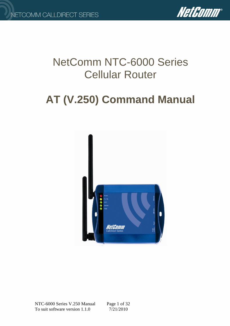
NetComm NTC-6000 Series Cellular Router
AT (V.250) Command Manual

NTC-6000 Series V.250 Manual Page 2 of 32
To suit software version 1.1.0 7/21/2010
CONTENTS Introduction ............................................................................................................................. 4
Product overview ................................................................................................................ 4
Command and configuration reference ................................................................................... 5 Overview ............................................................................................................................. 5 Operating states ................................................................................................................... 5 Syntax Description .............................................................................................................. 6
DTE commands lines ...................................................................................................... 6
Command line general format ........................................................................................ 6 Command line echo ........................................................................................................ 6 Types of DTE commands ............................................................................................... 6
DTE command syntax..................................................................................................... 7 Basic syntax command format ........................................................................................ 7 S-parameters ................................................................................................................... 7 Extended syntax commands ............................................................................................ 8
AT Command specifications................................................................................................... 9
V.250 Configuration commands ............................................................................................. 9 &F Restore factory defaults .......................................................................................... 9 Z Soft reset and restore saved settings ........................................................................... 9
&W Save configuration to non-volatile memory ........................................................... 9 E Command Echo ........................................................................................................... 9 Q Quiet mode ................................................................................................................ 10
V Result code form ....................................................................................................... 10
I Identification ............................................................................................................. 10 ^CROK Send OK response to <CR> .......................................................................... 10 ^NOLF Disable sending <LF> in response messages ................................................... 11
^NOER Disable ERROR response to unknown commands ....................................... 11 ^PAST Pass unknown V.250 commands to phone module. ......................................... 11
^EMUL Enable special device emulation ................................................................... 11 DCE-DTE Interface commands ............................................................................................ 13
&D DTR Configuration ............................................................................................... 13 &S DSR Configuration ............................................................................................... 14
&C DCD Configuration ............................................................................................... 14 &N RI Configuration ................................................................................................... 14 +IPR Local RS-232 interface baud rate ..................................................................... 15
+ICF Local RS-232 interface character framing .............................................................. 15 +IFC Local RS-232 flow control................................................................................ 16
V.250 Session management commands ................................................................................ 17 D Dial (Establish Connection) ...................................................................................... 17
H Hang Up .................................................................................................................... 19 O Return to On line state .............................................................................................. 19 +++ Enter On line command state ................................................................................ 19
Cellular Packet Session management commands ................................................................. 20 ^PRFL Profile Configuration ........................................................................................ 20
^GASC Enable cellular packet session auto connect ................................................. 21 ^GRST End Cellular Packet Session ............................................................................. 21
PAD Configuration commands ............................................................................................. 22
^IDNT PAD identification string .................................................................................. 22 ^ICTO Inter-character timer .......................................................................................... 22
NTC-6000 Series V.250 Manual Page 3 of 32
To suit software version 1.1.0 7/21/2010
LAN Configuration commands............................................................................................. 23 ^ETHI Set the LAN Ethernet IP address ...................................................................... 23 ^ETHN Set the local Ethernet Mask .......................................................................... 23 ^ETHR Print the Route Table ........................................................................................ 23
^MACA Set the LAN Ethernet MAC address ............................................................. 24 ^IFCG Print the Interface Configuration ...................................................................... 24 ^PPPOE Enable PPPoE Mode ..................................................................................... 24 ^MASQ Enable DNS masquerade. ............................................................................. 24 ^DHCP Configure DHCP server ................................................................................ 25
^MAPP Configure NAT translation ........................................................................... 26 Miscellaneous, system, test and diagnostic commands ........................................................ 27
^RESET Reset the cellular router ................................................................................ 27
^FACTORY Reset the cellular router configuration .................................................. 27 ^COPT Configuration options. ...................................................................................... 27 ^PRT Periodic reset timer ........................................................................................... 28 ^GLUP Perform a Domain name lookup ....................................................................... 28 ^PING Ping an IP address ............................................................................................. 29
^LTPH Periodically Ping an IP address......................................................................... 29 +CSQ Obtains the Signal Strength .............................................................................. 30
Appendix A ........................................................................................................................... 31
Addressed Serial Protocol Specification ........................................................................... 31

NTC-6000 Series V.250 Manual Page 4 of 32
To suit software version 1.1.0 7/21/2010
Introduction
Product overview
In addition to traditional router functionality the NetComm NTC-6000 series cellular
routers (NTC) have been designed to facilitate the use of packet switched digital cellular
networks in legacy applications which support a V.250 (V.25ter, AT, Hayes compatible)
modem interface.
These applications often do not support the PPP and TCP/IP transport commonly supported
by the digital cellular networks.
Although the NTC-6000 series includes a cellular terminal module the external application
does not communicate directly with the digital cellular terminal, instead V.250 (AT)
commands and data are processed by the NTC.
Any V.250 commands that the NTC does not process internally may optionally be passed to
the internal cellular terminal in order to access terminal specific features.
Additionally the NTC can be configured for use as a standard circuit switched cellular data
modem.

NTC-6000 Series V.250 Manual Page 5 of 32
To suit software version 1.1.0 7/21/2010
Command and configuration reference
Overview
V.250 (AT) commands, issued from your application are used to control and configure the
NTC.
The NTC provides compatibility with legacy applications through compatibility with the
standard V.250 AT command set, these commands can be used to control the basic
functionality of the terminal.
In addition the NTC extends the V.250 command set to include a set of commands that can
be used to configure and operate the NTC‟s unique features without interfering with
operation of the basic V.250 interface.
Operating states
In this manual reference is made to command state, online command state and online
data state, these states are defined as follows: -
command state:
In Command State, the terminal is not communicating with a remote station, and ready to
accept V.250 commands.
Data from the local DTE are treated as command lines and processed by the terminal and
responses are sent to the local DTE.
The terminal enters this state upon power-up, and when a call is disconnected.
online command state:
In Online Command State, the terminal is communicating with a remote station, but treats
data from the local DTE as command lines and sends responses to the local DTE.
Data received from the remote station during Online Command State is buffered in the
terminal until Online Data State is once again entered (by a command from the DTE).
Data previously transmitted by the local DTE and buffered by the terminal will be
transmitted from the buffer to the remote station during Online Command State.
Online Command State may be entered from Online Data state through the use of the „+++‟
escape sequence or via change of DTR state as configured by the &D command.
online data state:
In Online Data State, the terminal is communicating with a remote station.
Data signals from the DTE are treated as data and transmitted to the remote station,
and data received from the remote station are delivered to the DTE.
Data and control signals are monitored by the terminal to detect events such as loss of the
remote connection and DTE requests for disconnection or switching to Online Command
state.
Online Data State is entered by successful completion of a command to originate or answer
a call, by automatically answering a call, by a DTE command to return to Online Data state
from Online Command state or in response to the DTR signal as configured by the &D
command.

NTC-6000 Series V.250 Manual Page 6 of 32
To suit software version 1.1.0 7/21/2010
Syntax Description
This section provides a brief description of the syntax used for the NTC-6000 series AT
command set. See the ITU-T recommendation V.250 for additional information.
DTE commands lines
In the descriptions that follow, words enclosed in angle brackets are references to
command elements or parameters, the brackets are not included in the command line.
Words enclosed in [square brackets] represent optional items; such items may be omitted
from the command line again the brackets are not included in the command line.
Other characters that appear in syntax descriptions shall appear in the places shown.
For clarity terminal responses are mentioned in terms of their alphabetic format; the actual
response issued will depend on the setting of parameters that affect response formats (e.g.
Q and V commands).
Command line general format
A command line is made up of three elements: the prefix, the body, and the termination
character.
The command line prefix consists of the characters "AT" or "at".
The body is made up of individual commands as specified later in this document.
Space characters are ignored and may be used freely for formatting purposes, unless
they are embedded in numeric or string constants.
The termination character may not appear in the body.
The terminal is capable of accepting 128 characters in the body.
Command line echo
The terminal may echo characters received from the host during command state and online
command state back to the host, depending on the setting of the E command. If enabled,
characters received from the host are echoed at the same rate, parity, and format as
received.
Characters not recognized as valid in the command line or of incomplete or improperly
formed command line prefixes are not echoed.
Types of DTE commands
There are two types of commands: action commands and parameter commands.
Action commands may be "executed" (to invoke a particular function of the terminal, which
generally involves more than the simple storage of a value for later use), or "tested" (to
determine whether or not the terminal implements the action command, and, if parameters
are associated with the action, the ranges of parameter values that are supported).
Parameter commands may be "set" (to store a value or values for later use), "read" (to
determine the current value or values stored), or "tested" (to determine whether or not the
equipment implements the parameter, and the ranges of values supported).

NTC-6000 Series V.250 Manual Page 7 of 32
To suit software version 1.1.0 7/21/2010
DTE command syntax
Two different command formats as specified by the 2.250 specification are supported these
are basic and extended commands as described below.
Basic syntax command format
The format of Basic Syntax commands, except for the D and S commands, is as follows:
command> [ number ]
Where command> is either a single character, or the "&" character followed by a
single character. Characters used in command> shall be taken from the set of
alphabetic characters.
<number> may be a string of one or more characters from "0" through "9"
representing a decimal integer value. Commands that expect a number> are noted
in the description of the command.
If a command does not expect a number> and a number is present, an ERROR is
generated. All leading "0"s in number> are ignored by the terminal.
Additional commands may follow a command (and associated parameter, if any) on
the same command line without any character required for separation. The actions
of some commands cause the remainder of the command line to be ignored (e.g. A).
Special Note:
As an extension to the V.250 standard basic commands in the NTC-6000 series will also
accept test and query syntax described as below.
command ?
The current values (if any) stored for the parameter are sent to the terminal in an
information text response.
The format of this response is described in the definition of the parameter. Generally, the
values will be sent in the same form in which they would be issued by the host in a
parameter setting command
command ?
If the terminal does not recognize the indicated command, it returns an ERROR result code
and terminates processing of the command line.
If the terminal does recognize the parameter name, it shall return an information text
response to the host, followed by an OK result code. The information text response
shall indicate the <numbers> supported by the terminal.
S-parameters
Commands that begin with the letter "S" constitute a special group of parameters known as
"S-parameters". These differ from other commands in important respects. The number
following the "S" indicates the "parameter number" being referenced. If the number is not
recognized as a valid parameter number, an ERROR result code is issued. Immediately

NTC-6000 Series V.250 Manual Page 8 of 32
To suit software version 1.1.0 7/21/2010
following this number, either a "?" or " " character shall appear. "?" is used to read the
current value of the indicated S-parameter; " " is used to set the S-parameter to a new
value.
S parameter_number ?
S parameter_number [ value ]
If the " " is used, the new value to be stored in the S-parameter is specified in decimal
following the " ". If no value is given (i.e. the end of the command line occurs or the next
command follows immediately), an ERROR result code issued and the stored value left
unchanged.
The ranges of acceptable values are given in the description of each S-parameter.
If the "?" is used, the terminal transmits a single line of information text to the host.
This information text consists of exactly three characters, giving the value of the S-
parameter in decimal, with leading zeroes included.
Extended syntax commands
Both actions and parameters have names, which are used in the related commands. Names
always begin with the character " " or "^".
Following the" " or "^", from one to sixteen (16) additional characters appear in the
command name.
The command interpreter in the terminal considers lower-case characters to be the same as
their upper-case equivalents.
Values
When subparameters are associated with the execution of an action, or when setting a
parameter, the command may include specification of values. This is indicated by the
appearance of value in the descriptions below.

NTC-6000 Series V.250 Manual Page 9 of 32
To suit software version 1.1.0 7/21/2010
AT Command specifications
V.250 Configuration commands
&F Restore factory defaults
Loads the terminal configuration with factory default values.
The factory default values for each parameter command can be found in the
description for each command in this document.
Note this applies to certain V.250 parameters ONLY, to perform a complete factory
reset refer to the ^FACTORY command.
Default: N/A
Command values: N/A
Z Soft reset and restore saved settings
Loads the terminal configuration to non-volatile memory
Default: N/A
Command values: N/A
&W Save configuration to non-volatile memory
Saves the terminal configuration to non-volatile memory.
The saved configuration values will be restored automatically on power up or if the
Z command is issued.
Default: N/A
Command values: N/A
E Command Echo
Whilst in command mode, controls the echo of characters received by the terminal
from the host.
Default: 1 Storage: &W Command
Command values:
E0 Disable echo of incoming characters in command mode.
E1 Enable echo of incoming characters in command mode.

NTC-6000 Series V.250 Manual Page 10 of 32
To suit software version 1.1.0 7/21/2010
Q Quiet mode
Whilst in command mode, controls whether the terminal will send result codes and
unsolicited responses to the host.
NB this does not suppress the terminal from sending solicited responses.
Default: 1 Storage: &W Command
Command values:
Q0 Send result codes and unsolicited responses.
Q1 Do not end result codes and unsolicited responses.
V Result code form
Selects whether the terminal sends long form (verbose) or short-form (numeric)
responses to the host.
Default: 1 Storage: &W Command
Command values:
V0 Send short form (numeric) codes.
V1 Send long form (verbose) result codes.
I Identification
Reports information to the host that may be used to help identify the product.
Default: 0
Command values:
I0 Report product identity.
I1 Report software version.
^CROK Send OK response to <CR>
Enables or disables sending of an OK response when the unit receives the <CR>
character by itself.
Default: 0 Storage: &W Command
Command values:
^CROK=0 Do not send OK in response to <CR>
^CROK=1 Send OK in response to <CR>

NTC-6000 Series V.250 Manual Page 11 of 32
To suit software version 1.1.0 7/21/2010
^NOLF Disable sending <LF> in response messages
Enables or disables sending the <LF> character in response messages.
Default: 0 Storage: &W Command
Command values:
^NOLF=0 Send <CR><LF> in response messages
^NOLF=1 Send <LF> in response messages
^NOER Disable ERROR response to unknown commands
Enables or disables sending an ERROR response to unknown commands.
When the ERROR response is disabled the terminal will instead send an OK
response to unknown commands. This may allow the terminal to be used in
applications where the host issues AT commands that would otherwise be
incompatible with the CDM800.
Default: 0 Storage: &W Command
Command values:
^NOER=0 Send ERROR response to unknown commands.
^NOER=1 Send OK response to unknown commands
^PAST Pass unknown V.250 commands to phone module.
Enables or disables pass-through of V.250 commands that the NTC V.250
command interpreter does not recognize (IE any command not specifically listed in
this document) to the internal cellular telephone module.
Please see the appropriate the appendix at the end of this document for further
details of supported commands.
Default: 1 Storage: &W
Command values:
^PAST=0 Return ERROR or OK to unknown commands as per the ^NOER
setting.
^PAST=1 Forward unknown commands to the internal phone module.
^PAST=2 Forward all commands to phone module primary AT command port.
^EMUL Enable special device emulation
The ^EMUL command configures the NTC to emulate other devices.

NTC-6000 Series V.250 Manual Page 12 of 32
To suit software version 1.1.0 7/21/2010
Default: 0 Storage: &W Command
Command values:
^EMUL=0 Disable emulation router operates per this manual.
^EMUL=1 Emulate TMR trunked radio.

NTC-6000 Series V.250 Manual Page 13 of 32
To suit software version 1.1.0 7/21/2010
DCE-DTE Interface commands
&D DTR Configuration
This parameter determines how the terminal responds when the DTR circuit
changes state.
Default: &D0 Storage: &W
Command values:
&D0 Ignore DTR.
&D1 If in online data state upon an on-to-off transition, the terminal enters
online command state and issues an OK result code; the call remains
connected.
&D2 If in online data state or online command state upon an on-to-off
transition, the terminal performs an orderly clear-down of the call
and returns to command state.
Automatic answer is disabled while DTR remains off.
&D3 Terminal “Auto-dials” default remote station (as determined by
^DHST) on off-to-on transition of DTR and enters online data state.
Terminal ends call and enters command state on on-to-off transition
of DTR.
&D4 Terminal “Auto-dials” default remote station (as determined by
^DHST) on on-to-off transition of DTR and enters online data state.
Terminal ends call and enters command state on off-to-on transition
of DTR.
&D5 When DTR is off pass all commands directly to the internal cellular
engine.
When DTR is on commands are processed by the NTC V.250
command interpreter, any commands not processed by the NTC
V.250 command interpreter are passed to the cellular engine in
accordance with the ^PAST parameter.

NTC-6000 Series V.250 Manual Page 14 of 32
To suit software version 1.1.0 7/21/2010
&S DSR Configuration
This parameter determines how the terminal controls the state of the DSR circuit.
Default: &S0 Storage: &W
Command values:
&S0 DSR always ON.
&S1 DSR ON when signal present and phone registered on network.
&S2 DSR ON when cellular packet data session established.
&S3 DSR always OFF
&C DCD Configuration
This parameter determines how the terminal controls the state of the DCD circuit.
Default: &C1 Storage: &W
Command values:
&C0 DCD always ON.
&C1 DCD ON when connected to remote host.
&C2 DCD always OFF.
&C3 DCD ON when cellular PPP session established.
&N RI Configuration
This parameter determines how the terminal controls the state of the RI circuit.
Default: &N1 Storage: &W
Command values:
&N0 RI always ON.
&N1 RI simulates incoming ring.
&N2 RI always OFF.

NTC-6000 Series V.250 Manual Page 15 of 32
To suit software version 1.1.0 7/21/2010
+IPR Local RS-232 interface baud rate
This parameter determines the baud rate at which data will be sent and received on
the local RS-232 interface.
Default: 115200 Storage: &W
Command values:
+IPR=<rate>
Where <rate> is a one of the following: -
300, 1200,2400,4800,9600,19200,38400,57600,115200
+ICF Local RS-232 interface character framing
This parameter determines the character framing which used at the local RS-232
interface.
Default: 3,1 Storage: &W
Command values:
+ICF=<format>,[<parity>]
Where <format> is a single digit and determines the number of bits in the data bits,
the presence of a parity bit, and the number of stop bits in the start-stop frame
according to the following table: -
<format> Meaning 1 8 Data 2 Stop
2 8 Data 1 Parity 1 Stop
3 8 Data 1 Stop
4 7 Data 2 Stop
5 7 Data 1 Parity 1 Stop
6 7 Data 1 Stop
And where <parity> is a single digit and determines how the parity bit is generated
and checked, if present according to the following table: -
<parity> Meaning 0 Odd
1 Even
<parity> is ignored where format is one of 1,3,4 or 6.

NTC-6000 Series V.250 Manual Page 16 of 32
To suit software version 1.1.0 7/21/2010
+IFC Local RS-232 flow control
This parameter is used to control the operation of local flow control between the terminal
and the local DTE.
.
Default: 0,0 Storage: &W
Command values:
AT+IFC=<DCE_by_DTE>,<DTE_by_DCE>†
Where:
<DCE_by_DTE> Specifies the method to be used by the DTE to control
the flow of received data from the DCE.
<DTE_by_DCE> Specifies the method to be used by the DCE to control
the flow of transmitted data from the DTE.
The valid numeric variables for the +IFC command are as follows:
0 No Flow Control
2 Hardware
By default, the modem is set up as AT+IFC=2,2 to allow hardware flow
control in both directions.

NTC-6000 Series V.250 Manual Page 17 of 32
To suit software version 1.1.0 7/21/2010
V.250 Session management commands
D Dial (Establish Connection)
Establish a connection.
The type of connection established is dependant upon the format of the dial string
supplied as described below.
The NTC supports 2 different types of packet data connections as follows:-
Packet Data Call
The packet data connection (PPP Session) is terminated at the connected device, in
this case the NTC acts as a MODEM.
Packet Data Session
The packet data connection (PPP Session) is terminated at the NTC, in this case the
NTC acts as a ROUTER.
The NTC also supports Circuit Switched Data calls, in this case the NTC acts as a
traditional circuit switched MODEM.
Default: N/A Storage: N/A
Command values:
ATD*99# Sets up a Packet Data Call based on context #1 as set using the +CGDCONT
command.
The NTC supports only 1 packet data call at a time, this command will return
„BUSY‟ if another packet data call is in progress.
ATD*99***<n>#
Sets up a packet data call based on context #<n> as set using the +CGDCONT
command where <n> is the <cid> of the +CGDCONT context.
The NTC supports only 1 packet data call at a time, this command will return
„BUSY‟ if another packet data call is in progress.

NTC-6000 Series V.250 Manual Page 18 of 32
To suit software version 1.1.0 7/21/2010
ATD<n>
Establishes a Packet Data Session based on profile <n> as set using the ^PRFL
command or browser based configuration „profile number‟ on the „Data
Connection‟ page.
If the selected profile is configured for PAD client mode a PAD session is
established to the host defined in the profile.
ATD<phone number>
Originates a Circuit Switched Data call to <phone number>
ATD<host>[:<port>[:<protocol>]
Originates a PAD session to the <host> and <port> <protocol> provided.
The <host> parameter may be an IP address or hostname.
The <port> parameter is optional if not supplied the port number from the currently
selected profile is used.
The <protocol> is optional and may be one of “TCP” or “UDP”, if not supplied the
protocol from the currently selected profile is used.

NTC-6000 Series V.250 Manual Page 19 of 32
To suit software version 1.1.0 7/21/2010
H Hang Up
This command instructs the terminal to disconnect from the remote device
terminating any session in progress.
Default: N/A Storage: N/A
Command values: N/A
O Return to On line state
This command instructs the terminal to return to online data state and issue a
CONNECT or CONNECT text result code.
Default: N/A Storage: N/A
Command values: N/A
+++ Enter On line command state
If the terminal detects the „+++‟ escape sequence in online data state the terminal
will enter online command state.
Default: N/A Storage: N/A
Command values: N/A

NTC-6000 Series V.250 Manual Page 20 of 32
To suit software version 1.1.0 7/21/2010
Cellular Packet Session management commands
^PRFL Profile Configuration
The ^PRFL command allows one to configure up to four different dialing profiles
with different parameters.
NB: Some of these profiles may be factory configured and not reconfigurable by the
end user per telecommunications carrier requirements.
Default:
^PRFL: 1,atd*99#,,,0,0,0,0,0,telstra.internet
^PRFL: 2,atd*99#,,,0,0,0,0,0,telstra.datapack
^PRFL: 3,atd*99#,,,0,0,0,0,0,
^PRFL: 4,atd*99#,,,0,0,0,0,0,
^PRFL: 5,atd*99#,,,0,0,0,0,0,
^PRFL: 6,atd*99#,,,0,0,0,0,0,
Storage: Automatic
Command values:
^PRFL=<parameters listed below>
Defines a profile as per settings below.
^PRFL? Queries all current profile settings.
Argument Number/Type Parameters
1.) Profile Number: [1..6]
2.) Phone Number To Dial: atd*99#-For Packet Data Calls
3.) Username: Username For This Connection
4.) Password: Password For This Connection
5.) PAD Mode: 0=Disable PAD
1=TCP Connection
2=UDP Connection
6.) PAD Functionality: 0=Cellular router will act as client
1=Cellular router will act as server
7.) Local serial protocol: 0=No encoding, data is sent without any
encapsulation
1=Encode with Addressed Serial Protocol
(See appendix A for details)
9.) PAD Host: Where:
vvv.www.xxx.yyy - The IP address to connect
to when acting as a client
vvv.www.xxx.yyy - The trusted incoming IP
address to listen to when acting as server, set
to 0.0.0.0 to accept connections from any
remote address
10.) Port Connection: zzzzz - Port to connect to in client mode.

NTC-6000 Series V.250 Manual Page 21 of 32
To suit software version 1.1.0 7/21/2010
zzzzz – Port to listen to in server mode.
11) APN: Access Point Name of network to connect to.
^GASC Enable cellular packet session auto connect
Enables or disables automatic connection and log-in to the cellular packet network.
Default: 0 Storage: Automatic
Command values:
^GASC=0 Do not connect to cellular packet network.
^GASC=1 Connect to cellular packet network using profile 1
^GASC=2 Connect to cellular packet network using profile 2
^GASC=3 Connect to cellular packet network using profile 3
^GASC=4 Connect to cellular packet network using profile 4
^GASC=5 Connect to cellular packet network using profile 5
^GASC=6 Connect to cellular packet network using profile 6
^GRST End Cellular Packet Session
This command will kill the current cellular packet session and bring the modem to
Command State. NOTE: This command will tear down the cellular packet session in
an orderly manner and may take several seconds to complete.
Default: N/A Storage: N/A
Command values:
^GRST Kills the current cellular packet session.
NOTE: If ^GASC=1, the modem will detect that the session dropped and will
immediately reconnect. To fully disconnect, set ^GASC=0 and then issue the
^GRST command.

NTC-6000 Series V.250 Manual Page 22 of 32
To suit software version 1.1.0 7/21/2010
PAD Configuration commands
^IDNT PAD identification string
This command is used to configure an identification string to be sent at the
beginning of each PAD session.
This string will be sent followed by a terminating <LF> either as the first UDP
datagram or the first bytes of a TCP stream.
If this parameter is not set (empty) no identification data is sent, nor is the
terminating <LF>
Default: <empty> Storage: &W
Command values:
^IDNT=<ID> Where <ID> is a string with maximum length of 32 bytes.
^ICTO Inter-character timer
This command is used to configure the Inter-Character timeout used by the PAD
service when assembling packets for transmission.
The PAD will send a packet of data every time the buffer is full (512 Bytes) or if the
serial data line is idle for longer than the time specified by this command.
Default: 50 Storage: &W
Command values:
^PADM=<timeout> Where <timeout> is a number between 0 and 65535
milliseconds.

NTC-6000 Series V.250 Manual Page 23 of 32
To suit software version 1.1.0 7/21/2010
LAN Configuration commands The commands below are used to configure the Ethernet LAN interface. There is no error
checking beyond octet validation (Four octets of 0-255) for any of the Ethernet address
assignments. E.g. If you set the netmask to an invalid address, the modem will accept it but
may unable to transfer via the LAN interface.
^ETHI Set the LAN Ethernet IP address
This command will set the LAN interface IP address.
Default: 192.168.20.1 Storage: Automatic
Command values:
^ETHI=<IP Address> Sets the Ethernet IP.
^ETHI? Queries the current Ethernet IP.
^ETHN Set the local Ethernet Mask
This command will set the LAN interface IP netmask.
Default: 255.255.255.0 Storage: Automatic
Command values:
^ETHN=<netmask> Sets the Ethernet mask.
^ETHN? Queries the current Ethernet mask.
^ETHR Print the Route Table
This command will print a copy of the modem‟s routing table.
Default: N/A Storage: N/A
Command values:
^ETHR? Prints the modem‟s routing table

NTC-6000 Series V.250 Manual Page 24 of 32
To suit software version 1.1.0 7/21/2010
^MACA Set the LAN Ethernet MAC address
This command will set the LAN interface Ethernet MAC address.
To reset the MAC address back to the factory configured address use the command
“AT^MACA=” and then reboot the router.
Default: factory unique Storage: Automatic
Command values:
^MACA=<MAC Address> Sets the Ethernet MAC address.
^MACA? Queries the current Ethernet MAC address.
^IFCG Print the Interface Configuration
This command will print the NTC IP interface configuration details.
Default: N/A Storage: N/A
Command values:
^IFCG? Prints the router‟s IP interface configuration details.
^PPPOE Enable PPPoE Mode
Enables or disables PPPoE mode.
Default: 0 Storage: Automatic
Command values:
^PPPOE=0 Disable PPPoE mode.
^PPPOE=1 Enable PPPoE mode.
^MASQ Enable DNS masquerade.
Enables or disables DNS masquerading.
Default: 0 Storage: Automatic
Command values:
^MASQ=0 Disable DNS masquerading.
^MASQ=1 Enable DNS masquerading.

NTC-6000 Series V.250 Manual Page 25 of 32
To suit software version 1.1.0 7/21/2010
^DHCP Configure DHCP server
This command performs configures the NTC DHCP server.
Default: ^DHCP: 192.168.20.100,192.168.20.199,86400,,
Storage: Automatic
Command values:
^DHCP= <First IP address>,<Last IP address>,<Lease Time>,<DNS1>,<DNS2>
Where:
< First IP address > First IP address in IP address pool
< Last IP address > Last IP address in IP address pool
< Lease Time > DHCP Lease time in seconds
<DNS1> Primary DNS server IP address
<DNS2> Primary DNS server IP address
If none of the above parameters are supplied the DHCP is disabled.
^DHCP? Queries DHCP configuration
Where:
< First IP address > First IP address in IP address pool
< Last IP address > Last IP address in IP address pool
< Lease Time > DHCP Lease time in seconds
<DNS1> Primary DNS server IP address
<DNS2> Secondary DNS server IP address

NTC-6000 Series V.250 Manual Page 26 of 32
To suit software version 1.1.0 7/21/2010
^MAPP Configure NAT translation
This command can be used to configure the NTC‟s NAT table.
Default: N/A Storage: Automatic
Command values:
^MAPP= <Mapping number>, <Protocol> <source IP address>,<incoming port
number>,<destination IP address>,<destination port number>
Where:
<Mapping number> The number of the NAT mapping
<Protocol> TCP/UDP/All
<source IP address> IP address of remote client
<incoming port number> incoming port number
<destination IP address> IP address
<destination port number> destination port number
The NTC NAT function can be used to forward incoming TCP connections or UDP
datagrams to an alternative IP address and port number.
The <source IP address> parameter may be set to 0.0.0.0 to accept connections from
ANY host otherwise this translation will only apply to connections from the
specified host.
The <incoming port number> parameter specifies the port number that the cellular
router listens or accepts datagrams on.
The <destination IP address> parameter specifies the IP address to redirect
connections/datagrams to.
The < destination port number > parameter specifies the port number to redirect
connections/datagrams to.
^MAPP? Queries NAT configuration

NTC-6000 Series V.250 Manual Page 27 of 32
To suit software version 1.1.0 7/21/2010
Miscellaneous, system, test and diagnostic commands
^RESET Reset the cellular router
This command initiates a soft reset (reboot) of the NTC, any active PAD and
cellular packet data sessions are abruptly terminated.
Default: N/A Storage: NA
Command values:
N/A
^FACTORY Reset the cellular router configuration
This command resets the cellular routers configuration to factory defaults, this resets
ALL configuration data.
Default: N/A Storage: Automatic
Command values:
N/A
^COPT Configuration options.
This command can be used to show or set a number of terminal specific options.
The command expects / returns an integer value between 0 and 255 which
represents a bitmap of various options.
Default: 0 Storage: Automatic
Command values:
^COPT=<bitmap>
Where the bits in <bitmap> are defined as follows: -
1 Banner off Do not show power on welcome message.
2 Connect message off Do not show connection progress messages.

NTC-6000 Series V.250 Manual Page 28 of 32
To suit software version 1.1.0 7/21/2010
^PRT Periodic reset timer
This command is used to configure the periodic reset timer.
The periodic reset timer can be used to perform a complete system reboot at the end
of the specified time.
This is reboot is designed to function as closely as possible to removing and re-
applying power to the terminal (without actually doing so).
This reboot will occur at the specified interval regardless of any other condition.
NB if the device is in a “call” and the periodic reset timer expires the call will be
unexpectedly terminated.
The terminal does NOT perform an orderly clear down of the call from the
application point of view; it does however attempt an orderly shutdown of the
cellular module.
The periodic reset timer always starts from the time the terminal is powered up or
reset, even if ^PRT = 0. This means that if the terminal has been running for some
time and the user sets ^PRT to a value less than the period of time since the unit was
last reset the unit will immediately reset.
A value of 0 disables the periodic reset timer.
Default: 0 Storage: Automatic
Command values:
^PRT=<timeout> Where <timeout> is a number between 0 and 65535
minutes.
NOTE – This command can be used to perform a modem reset, i.e by sending
AT^PRT=1 means that within one second the modem will reboot.
^GLUP Perform a Domain name lookup
This command performs a domain name lookup for a given domain name such as
www.call-direct.com.au
Default: N/A Storage: NA
Command values:
^GLUP=<url> Perform a domain name lookup.
NTC-6000 Series V.250 Manual Page 29 of 32
To suit software version 1.1.0 7/21/2010
^PING Ping an IP address
This command performs a ping for a given IP address or domain name.
Default: N/A Storage: NA
Command values:
^PING= <domain name or IP address> Ping the domain name or IP address
^LTPH Periodically Ping an IP address
This command performs a periodic ping for a given IP address or domain name.
Default: ^LTPH: ,,0,0,0,-1 Storage: Automatic
Command values:
^LTPH = <Address 1>,
<Address 2>,
<timer>,<acceleration timer>,<failure count>
Where:
<Address 1> Primary address to ping
<Address 2> Backup address to ping
<timer> The periodic time to ping in secs (e.g. every 60 seconds)
<acceleration timer> The periodic time in secs to revert to if a ping fails
<failure count> The number of pings that can fail to trigger a reboot.
^LTPH? Queries ltph configuration
Where:
<Address 1> Primary address to ping
<Address 2> Backup address to ping
<timer> The periodic time to ping in secs (e.g. every 60 seconds)
<acceleration timer> The periodic time in secs to revert to if a ping fails
<failure count> The number of pings that can fail to trigger a reboot.
<reset count> The number of times the modem has been reset.

NTC-6000 Series V.250 Manual Page 30 of 32
To suit software version 1.1.0 7/21/2010
+CSQ Obtains the Signal Strength
This command queries the signal strength for the cellular interface.
Default: N/A Storage: N/A
Command values:
+CSQ Queries the signal strength

NTC-6000 Series V.250 Manual Page 31 of 32
To suit software version 1.1.0 7/21/2010
Appendix A
Addressed Serial Protocol Specification NetComm has implemented the following protocol to allow a master station
to communicate with a number of remote stations via GPRS.
In particular the master station must be able to identify individual
remote stations sending data to the master and in turn be able to direct
transmissions to a specific remote station.
In order to provide this addressability the following protocol is
defined.
All data will be sent encapsulated in HDLC like frames with the IP
address of the remote station (in standard network byte order) as the
first 4 information bytes of each frame, application data starts at the
5th byte of the information field of each frame.
Frame Format
A summary of the HDLC-like frame structure is shown below. This figure does not include bits inserted for synchronization (such as
start and stop bits for asynchronous links), nor any bits or octets
inserted for transparency. The fields are transmitted from left to
right.
+----------+----------+-------------+----------+
| Flag | Protocol | Information | Flag |
| 01111110 | 8/16 bits| * | 01111110 |
+----------+----------+-------------+----------+
NB The standard HDLC Address, Control and FCS fields are not used
or present.
Flag Field
The Flag Sequence indicates the beginning or end of a frame, and is
used for frame synchronization. The bit stream is examined for the
binary sequence 01111110 (hexadecimal 0x7e).
Transparency
An octet stuffing procedure is used. The Control Escape octet is
defined as binary 01111101 (hexadecimal 0x7d), most significant bit
first.
Each Flag Sequence and Control Escape octet, is replaced by a two
octet sequence consisting of the Control Escape octet followed by
the original octet exclusive-or'd with hexadecimal 0x20.
Escaped data is transmitted on the link as follows:
0x7e is encoded as 0x7d, 0x5e. (Flag Sequence)
0x7d is encoded as 0x7d, 0x5d. (Control Escape)

NTC-6000 Series V.250 Manual Page 32 of 32
To suit software version 1.1.0 7/21/2010
Protocol Field
The Protocol field is consistent with the ISO 3309 (HDLC) extension
mechanism for Address fields. All Protocols are assigned such that
the least significant bit of the most significant octet equals "0",
and the least significant bit of the least significant octet equals
"1".
Presently the only defined protocol type is 0x99 (Addressed Serial
Data).
i.e. All frames start with 0x7E, 0x99
Information Field
The infomation field is structured as follows.
+----------------+------------------+
| Remote Address | Application Data |
| 32 bits | * |
+----------------+------------------+
Where the remote address contains the IP address of the remote
device in network byte order.