Embed Size (px)
Citation preview
ASYNCHRONOUS THREE-PHASE MACHINE DRIVEN AS
GENERATOR BY A TWIN-SCREW EXPANDER
Claudia BORZEA1,2, Adrian SĂVESCU1, Iulian VLĂDUCĂ1,2, Adrian STOICESCU1,2 1Romanian Research and Development Institute for Gas Turbines COMOTI
2University Politehnica of Bucharest
Abstract. The paper presents the functioning regimes of a 132 kW asynchronous three-
phase machine, used for the expander-generator system in a compressed air energy
storage facility. The installation consists of a 110 kW twin-screw electro-compressor,
which supplies pressurized air up to ~16 bar into a 50 m3 storage vessel. The compressed
air is afterwards released from the reservoir into expander’s inlet, spinning its shaft. When
the expander’s shaft spins the electric machine over its synchronous speed, this one enters
in generator mode, supplying electric power into the grid. Two power analysers installed
on the automation control cabinet monitor the generated/absorbed power and the power
supplied/consumed by the system from the grid. Using the data acquired by means of
PLC during commissioning tests, we plotted the power curves, differential pressure and
significant temperatures, as well as the electric machine’s speed.
1. INTRODUCTION
The increasing use of the potential of renewable energy sources such as wind, biogas,
solar, hydro and compressed air energy storage (CAES) encourages the use of low-cost
generating systems, able to operate in remote areas, and driven by a diversity of prime movers
[1]. With wind turbine generators [2] and hydro generators [3, 4] as an alternative energy
source, the induction generators are being considered as an alternative choice to synchronous
generators due to their simplicity, ruggedness, reduced maintenance necessary, lower price,
brushless construction (for squirrel cage machines), absence of a separate direct current source,
self-protection against severe overloads and short circuits etc. Squirrel cage induction
generators with capacitor excitation, known as self-excited induction generators (SEIG), are
very suited and used in isolated systems [1].
At the present moment, the emphasis falls on using renewable energy resources cost-
effectively, for ensuring the quality and reliability of the power supply. Traditionally,
synchronous generators have been used for power generation, but induction generations are
increasingly being used in the present due to their advantageous features over the conventional
synchronous generators. Self-excited induction generators have been a considerable research
direction for a few decades until time being, due to their popularity as the simplest energy
conversion devices to produce off-grid electricity, in standalone mode, with various prime
movers and employing diverse conventional and renewable energy resources [1].
The major drawbacks of self-excited induction generators are the low voltage and
frequency adjustments needed under the speed of the prime mover, as well as for load
perturbations, or in other words the problem of regulating the voltage magnitude and voltage
frequency under load variation. The main decision whether to use an induction generator or a
synchronous one depends on a large number of variables. Not only the technical properties of
the machines have to be considered, but also the application and the systems into which the
generators will supply energy [5].
The paper focuses on the operation regimes of a 132 kW three-phase asynchronous
machine used for the expander-generator system of ROCAES compressed air energy storage
installation [6-8].
ACTUALITĂŢI ŞI PERSPECTIVE ÎN DOMENIUL MAŞINILOR ELECTRICEELECTRIC MACHINES, MATERIALS AND DRIVES PRESENT AND TRENDS – 2020 –
ISSN / ISSN-L: 1843-5912https://www.doi.org/10.36801/apme.2020.1.5
2/8
2. COMPRESSED AIR ENERGY STORAGE PLANT
2.1. Overview
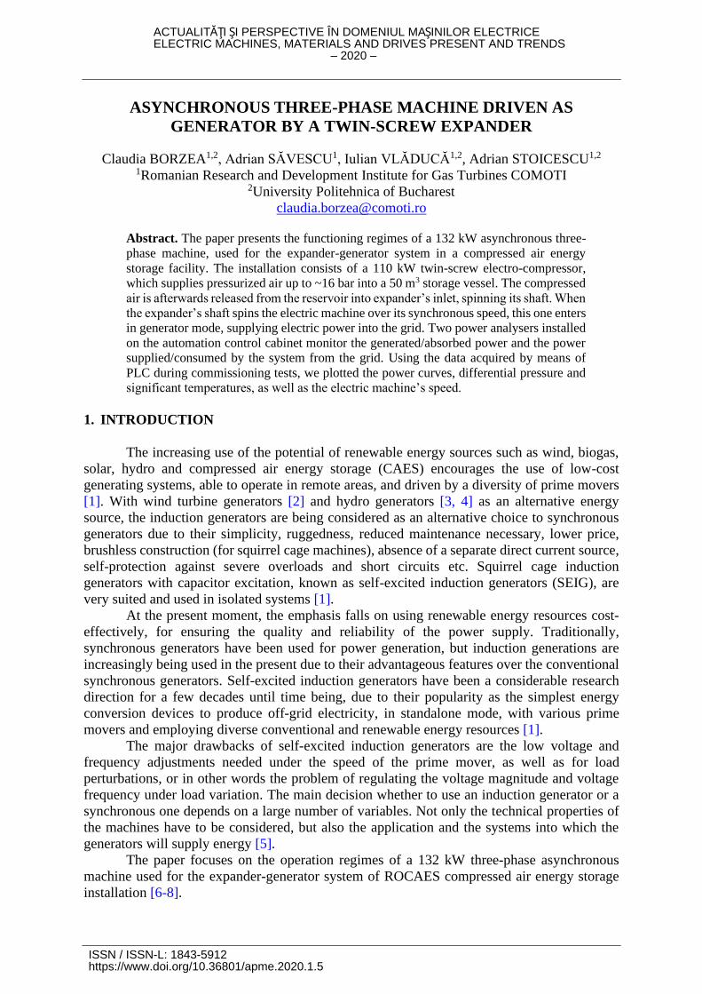
ROCAES installation (Figure 1) is a relatively low scale compressed air energy storage
prototype [6-8], making use of a manufactured reservoir to store the compressed air, and a water
tank for thermal conditioning. The demonstrative model makes use of a twin-screw compressor
and a twin-screw expander, electrically actuated by three-phased asynchronous machines. The
compressor is driven by a 110 kW asynchronous motor, supplying pressurized air into a 50 m3
storage unit. The expander is driven by the pressurized air released from the reservoir. Its shaft
spins a 132 kW asynchronous three-phase induction machine over its synchronous speed,
injecting electric power to the grid. The compressor and the expander have not been designed
for a simultaneous operation.
Fig. 1. ROCAES installation with automation and control room
During compressor’s operation, pressurised hot air is accumulated in the storage
reservoir. The lube oil tray passes through the thermal storage unit (5 m3 water tank) and
transfers heat to expander’s oil circuit [8]. An oil injection pump recirculates the oil on a bypass
circuit configured with a three-way MOV (Motor Operated Valve), thus ensuring the oil
heating. After the compressor stops, oil recirculation also stops automatically for thermal
energy conservation in the storage tank.
2.2. Advantages of using induction generator over synchronous generator
It can be stated without doubt that the synchronous motor has a difficult start-up, since
it is not able to develop electromagnetic torque unless the synchronism condition is fulfilled. In
order to start a synchronous motor, one can either use an auxiliary motor or asynchronous start-
up. Using an auxiliary motor for driving the rotor up to synchronous speed is less practiced,
since it rises the overall costs. Asynchronous start-up is possible only if the motor has an extra
short-circuit winding that has the same role as the squirrel cage at the asynchronous motor.
For a 200 kW synchronous generator driven by an air/gas twin-screw expander, in a
similar application [9], several manoeuvres are being required, along with a more complex
automation system. The electric machine is driven up to its synchronous speed by the air/gas
released into the expander, until reaching its synchronous speed, at the same frequency as the
3/8
electric grid (50 Hz), with very tight allowed tolerances. Then, only when the phase of the
machine and that of the electric grid are the same (the sinusoidal curves overlap), this one can
be coupled to the grid. Any phase shift can yank the synchronous generator and cause shocks,
sparks and overcurrents, which can harm the electric machine. The automation system ensures
protection switches which disrupt the machine’s circuit from the grid. For the 200 kW
synchronous generator, when this happens, the power line may fall.
Induction generators have a simpler construction than synchronous generators [10, 11],
are easier to operate, control, and maintain, and do not have synchronization problems [1].
Induction machines have been widely used in power generation and industrial applications [12]
for decades due to their numerous advantages like robust design and lower cost as compared to
synchronous machines. When a standalone induction generator is driven by a mechanical prime
mover, the remanent magnetisation in the rotor induces an electromagnetic field in stator
windings at a frequency proportional to rotor’s speed [13].
The asynchronous machine used in our application is firstly coupled to the electric
network, then started up as motor with a softstarter. The softstarter was chosen as a safer driver
than frequency inverter, as speed variation is unnecessary, the installation being intended to
generate at rated power (compressed air or electric power). Softstarters are a modern start-up
method, ensuring current limitation, along with the necessary torque and start timer, so as to
allow a smooth start-up and avoid mechanical and electrical shocks and strains. We provided
ultra-rapid fuses for thyristors protection, in case of short-circuit, as well as thermal relays.
ASU 315M-4 [14] squirrel cage three-phase induction machine chosen has an active
(shaft) power of 132 kW. Its characteristics are given in Table 1. At asynchronous generators,
an extra reactive power component appears [15], relatively high, which is interchanged with
the grid. For not putting an extra load on the grid, we provided a capacitor battery of 50 kVAr
to ensure the necessary capacitive reactive power (compensating induction reactive power).
Table 1. Asynchronous machine specifications
Motor
type
Rated
power
Rated
speed
Rated
current
@400V cos Ip/In Mp/Mn Mmax/Mn Mass
ASU
315M-4 132 kW 1470 rpm 225 A 95.0 % 0.89 7.4 2.0 3.0 820 kg
*Where: – Efficiency; Ip – Start-up current; In – Rated current; Mp – Start-up torque; Mn – Rated torque;
Mmax – Maximum torque.
For the given application, asynchronous generators offer undeniable advantages: Simple
construction and safe operation; Good technical performances (high start-up torque up to 2xMn,
high dynamic load capacity, good efficiency); Stability in operation, exploitation, manoeuvring,
as well as simple maintenance; Power supply directly from the three-phased alternative current
grid, connection to grid from start-up; Its operation can be fully automated: start-up – loading
– grid functioning, without human operator’s presence being necessary.
3. EXPANDER-GENERATOR SYSTEM
The electric power produced by the generator increases with the prime mover’s power.
The expander’s induction machine initially functions as asynchronous motor (launched with
softstarter) until reaching no-load speed (𝑑n
𝑑t= 0), afterwards being driven by the pressurised
air released, controllably, from the storage unit into the expander. When exceeding the
synchronous speed, the asynchronous machine enters automatically in generator mode, which
can generate a power of up to ~138 kVA. Choosing an asynchronous generator significantly
4/8
eases the coupling to grid, as no manoeuvres are required for synchronisation with the electrical
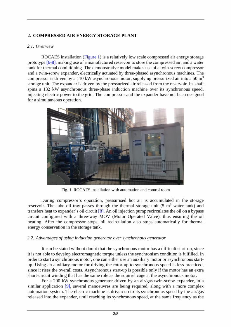
network’s frequency. The expander-generator system (Figure 2) was commissioned at Popeci
Heavy Equipment industrial hall in Craiova, Romania.
Fig. 2. Expander-generator system
The expander’s asynchronous machine receives electric power from the AC three-phase
network by connecting its stator to this one, energy that it converts in mechanical power to turn
the shaft. When the shaft is spun mechanically over synchronous speed, by the compressed air
released from the reservoir, the rotor will have a higher speed than the stator, pulling after it the
stator’s magnetic field, and thus becoming inductor.
Entering into generation regime is realised by opening the valve on expander’s inlet at
a certain angle, considering the instantaneous storage pressure. Subsequent finer adjustments
of the injected power can be made, affected by a series of limitative parameters such as: inlet
pressure, discharge pressure (differential pressure between inlet and outlet), air temperature, oil
temperature etc.
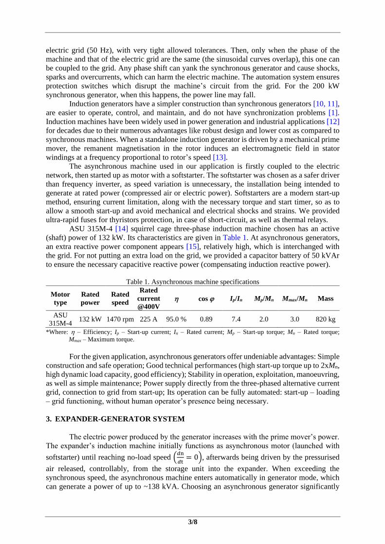
The two power analysers installed on the automation control cabinet monitor the
generated/absorbed power of the asynchronous machine (Figure 3 left), and the overall power
supplied/consumed by the system into/from the electric grid (Figure 3 right). As it can be
observed, the power is negative, indicating generation. The values displayed on the network
analyser (right) are slightly lower, since a share of the generated power is used to power the
electrical consumers within the automation cabinets.
Fig. 3. Power analysers displaying the generated power (left) and power supplied to grid (right)
5/8
4. COMMISSIONING TESTS AND ACQUIRED DATA ANALYSIS
The purpose of the automation Supervisory Control and Data Acquisition (SCADA)
system, represented by two sets of drives and automation cabinets, one for compressor and one
for expander automation, is to monitor, control and regulate the operation parameters of
thermal, mechanical and electrical processes, in order to keep these ones within safe operation
limits. The information from the transducers monitoring installation’s important parameters is
transmitted to the two separate VersaMax PLCs located in the automation cabinets, for the
independent operation of expander and compressor skids [8]. The analogue I/O (inputs/outputs)
signals for varying parameters are transmitted in 4-20 mA unified current signal, while digital
I/O (open/close, on/off type) are transmitted in 0-24 VDC voltage signal.
The air reservoir was filled for about 2 hours of compressor operation, reaching a
pressure of ~16 bar. Then, this one was shut down as the automation system was designed for
not allowing a simultaneous operation with the expander. The twin-screw expander’s air inlet
valve was therefore opened, and the electric machine was started in motor regime, until reaching
no load speed. Pressurised air from the storage unit was released, opening the reservoir valve
towards the expander.
A minimum air pressure condition 2 bar was set at the inlet in the software program
realised in Proficy Machine Edition, dedicated for VersaMax PLCs. If not meeting this
condition, the expander goes through an automatic shutdown sequence. The condition was set
considering minimum air pressure in the reservoir dropping down to 4-5 bar, considering the
pressure losses until air reaches expander’s inlet. As well, a similar software shutdown sequence
occurs when the asynchronous machine enters again in motor regime and its consumed power
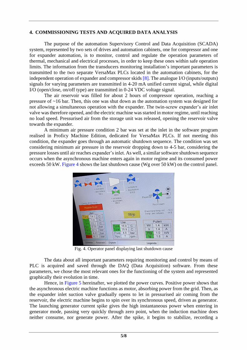
exceeds 50 kW. Figure 4 shows the last shutdown cause (Wg over 50 kW) on the control panel.
Fig. 4. Operator panel displaying last shutdown cause
The data about all important parameters requiring monitoring and control by means of
PLC is acquired and saved through the DAQ (Data Acquisition) software. From these
parameters, we chose the most relevant ones for the functioning of the system and represented
graphically their evolution in time.
Hence, in Figure 5 hereinafter, we plotted the power curves. Positive power shows that
the asynchronous electric machine functions as motor, absorbing power from the grid. Then, as
the expander inlet suction valve gradually opens to let in pressurised air coming from the
reservoir, the electric machine begins to spin over its synchronous speed, driven as generator.
The launching generator current spike gives the high instantaneous power when entering in
generator mode, passing very quickly through zero point, when the induction machine does
neither consume, nor generate power. After the spike, it begins to stabilize, recording a
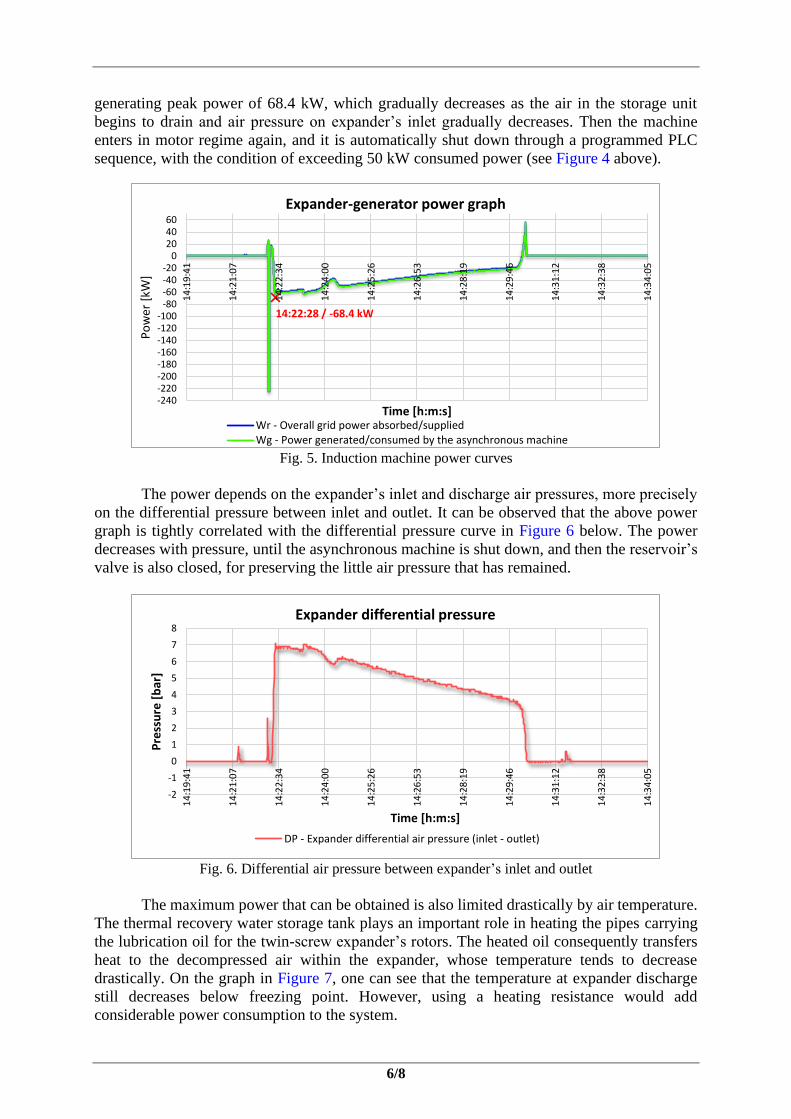
6/8
generating peak power of 68.4 kW, which gradually decreases as the air in the storage unit
begins to drain and air pressure on expander’s inlet gradually decreases. Then the machine
enters in motor regime again, and it is automatically shut down through a programmed PLC
sequence, with the condition of exceeding 50 kW consumed power (see Figure 4 above).
Fig. 5. Induction machine power curves
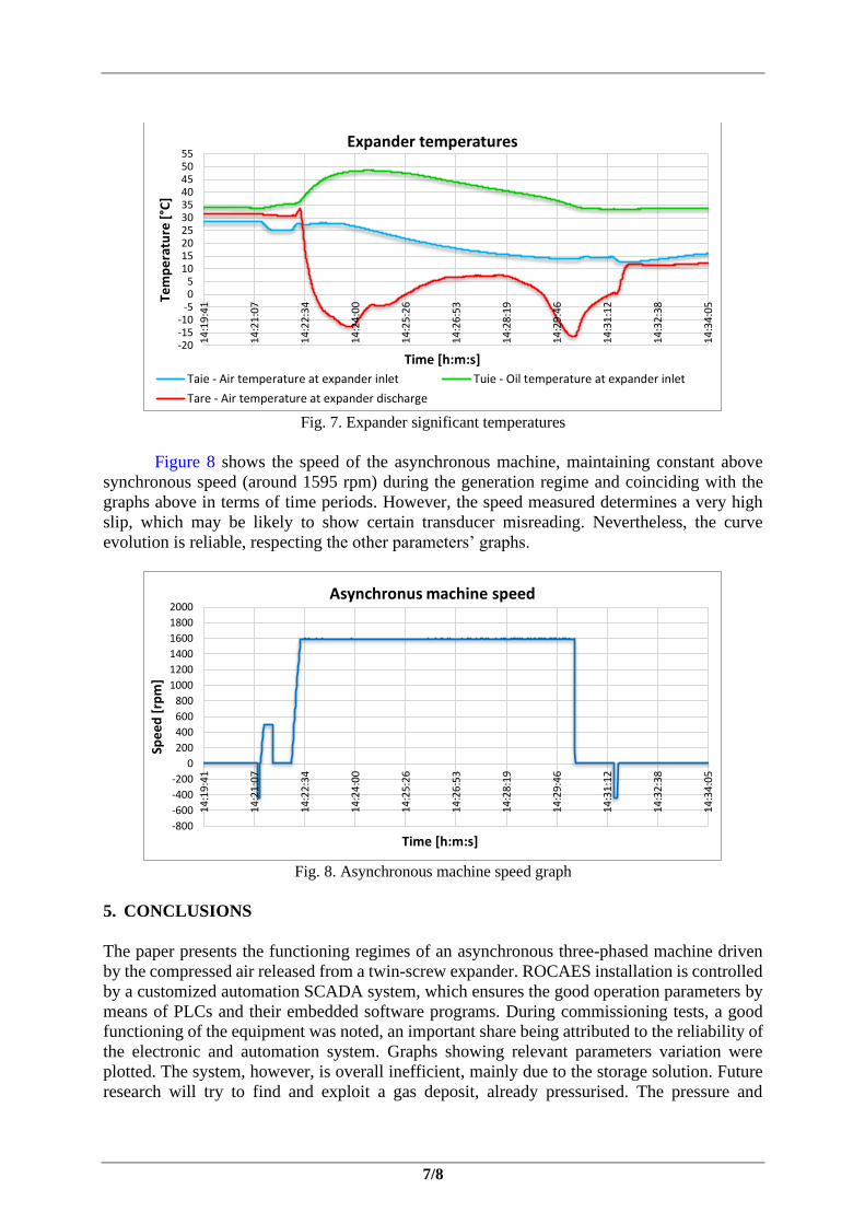
The power depends on the expander’s inlet and discharge air pressures, more precisely
on the differential pressure between inlet and outlet. It can be observed that the above power
graph is tightly correlated with the differential pressure curve in Figure 6 below. The power
decreases with pressure, until the asynchronous machine is shut down, and then the reservoir’s
valve is also closed, for preserving the little air pressure that has remained.
Fig. 6. Differential air pressure between expander’s inlet and outlet
The maximum power that can be obtained is also limited drastically by air temperature.
The thermal recovery water storage tank plays an important role in heating the pipes carrying
the lubrication oil for the twin-screw expander’s rotors. The heated oil consequently transfers
heat to the decompressed air within the expander, whose temperature tends to decrease
drastically. On the graph in Figure 7, one can see that the temperature at expander discharge
still decreases below freezing point. However, using a heating resistance would add
considerable power consumption to the system.
14:22:28 / -68.4 kW
-240-220-200-180-160-140-120-100
-80-60-40-20
0204060
14
:19
:41
14
:21
:07
14
:22
:34
14
:24
:00
14
:25
:26
14
:26
:53
14
:28
:19
14
:29
:46
14
:31
:12
14
:32
:38
14
:34
:05
Po
wer
[kW
]
Time [h:m:s]
Expander-generator power graph
Wr - Overall grid power absorbed/suppliedWg - Power generated/consumed by the asynchronous machine
-2
-1
0
1
2
3
4
5
6
7
8
14
:19
:41
14
:21
:07
14
:22
:34
14
:24
:00
14
:25
:26
14
:26
:53
14
:28
:19
14
:29
:46
14
:31
:12
14
:32
:38
14
:34
:05
Pre
ssu
re [
bar
]
Time [h:m:s]
Expander differential pressure
DP - Expander differential air pressure (inlet - outlet)
7/8
Fig. 7. Expander significant temperatures
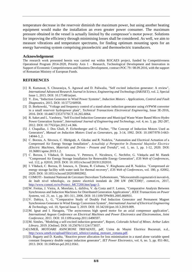
Figure 8 shows the speed of the asynchronous machine, maintaining constant above
synchronous speed (around 1595 rpm) during the generation regime and coinciding with the
graphs above in terms of time periods. However, the speed measured determines a very high
slip, which may be likely to show certain transducer misreading. Nevertheless, the curve
evolution is reliable, respecting the other parameters’ graphs.
Fig. 8. Asynchronous machine speed graph
5. CONCLUSIONS
The paper presents the functioning regimes of an asynchronous three-phased machine driven
by the compressed air released from a twin-screw expander. ROCAES installation is controlled
by a customized automation SCADA system, which ensures the good operation parameters by
means of PLCs and their embedded software programs. During commissioning tests, a good
functioning of the equipment was noted, an important share being attributed to the reliability of
the electronic and automation system. Graphs showing relevant parameters variation were
plotted. The system, however, is overall inefficient, mainly due to the storage solution. Future
research will try to find and exploit a gas deposit, already pressurised. The pressure and
-20-15-10
-505
10152025303540455055
14
:19
:41
14
:21
:07
14
:22
:34
14
:24
:00
14
:25
:26
14
:26
:53
14
:28
:19
14
:29
:46
14
:31
:12
14
:32
:38
14
:34
:05Te
mp
era
ture
[°C
]
Time [h:m:s]
Expander temperatures
Taie - Air temperature at expander inlet Tuie - Oil temperature at expander inlet
Tare - Air temperature at expander discharge
-800
-600
-400
-200
0
200
400
600
800
1000
1200
1400
1600
1800
2000
14
:19
:41
14
:21
:07
14
:22
:34
14
:24
:00
14
:25
:26
14
:26
:53
14
:28
:19
14
:29
:46
14
:31
:12
14
:32
:38
14
:34
:05
Spe
ed
[rp
m]
Time [h:m:s]
Asynchronus machine speed
8/8
temperature decrease in the reservoir diminish the maximum power, but using another heating
equipment would make the installation an even greater power consumer. The maximum
pressure obtained in the vessel is actually limited by the compressor’s motor power. Solutions
for improving the efficiency through minimising losses shall be considered. As well, we aim to
measure vibrations and temperature spectrums, for finding optimum mounting spots for an
energy harvesting system comprising piezoelectric and thermoelectric transducers.
Acknowledgement The research work presented herein was carried out within ROCAES project, funded by Competitiveness
Operational Program 2014-2020, Priority Axis 1 – Research, Technological Development and Innovation in
Support of Economic Competitiveness and Business Development, contract POC 79 / 08.09.2016, with the support
of Romanian Ministry of European Funds.
REFERENCES
[1] R. Kumawat, S. Chourasiya, S. Agrawal and D. Paliwalia, "Self excited induction generator: A review",
International Advanced Research Journal in Science, Engineering and Technology (IARJSET), vol. 2, Special
Issue 1, 2015. DOI: 10.17148/iarjset.
[2] Y. Zou, "Induction Generator in Wind Power Systems", Induction Motors - Applications, Control and Fault
Diagnostics, 2015. DOI: 10.5772/60958.
[3] D. Borkowski, "Voltage and frequency control of a stand-alone induction generator using sVPWM converter
in a small reservoir hydropower plant", Technical Transactions Electronical Engineering, Issue 3E-2016,
2016. DOI: 10.4467/2353737XCT.16.265.6064.
[4] R. Saket and L. Varshney, "Self Excited Induction Generator and Municipal Waste Water Based Micro Hydro
Power Generation System", International Journal of Engineering and Technology, vol. 4, no. 3, pp. 282-287,
2012. DOI: 10.7763/ijet.2012.v4.366.
[5] J. Chapallaz, J. Dos Ghali, P. Eichenberger and G. Fischer, "The Concept of Induction Motors Used as
Generators", Manual on Induction Motors Used as Generators, pp. 3-14, 1992. DOI: 10.1007/978-3-663-
14044-3_2.
[6] C. Borzea, A. Săvescu, C. Hărăguță, A. Găzdac and R. Nedelcu, "Automation and Electrical Actuation of a
Compressed Air Energy Storage Installation", Actualităţi şi Perspective în Domeniul Maşinilor Electrice
(Electric Machines, Materials and Drives - Present and Trends)", vol. 1, no. 1, pp. 1-12, 2020. DOI:
10.36801/apme.2019.1.2.
[7] C. Borzea, I. Vlăducă, D. Ionescu, V. Petrescu, F. Niculescu, C. Nechifor, G. Vătășelu and M. Hanek
"Compressed Air Energy Storage Installation for Renewable Energy Generation", E3S Web of Conferences,
vol. 112, p. 02010, 2019. DOI: 10.1051/e3sconf/201911202010.
[8] I. Vlăducă, C. Borzea, D. Ionescu, A. Ţăranu, R. Ciobanu, V. Ringheanu and R. Nedelcu. "Compressed air
energy storage facility with water tank for thermal recovery", E3S Web of Conferences, vol. 180, p. 02002,
2020. DOI: 10.1051/e3sconf/202018002002.
[9] COMOTI - Institutul National de Cercetare Dezvoltare Turbomotoare, "Microcentrală cogenerativă inovativă,
de înalt nivel tehnologic, cu putere electrică instalată de 200 kW (MCT200)", comoti.ro, 2017,
http://www.comoti.ro/ro/Proiect_MCT200.htm?pag=3.
[10] W. Freitas, J. Vieira, A. Morelato, L. daSilva, V. da Costa and F. Lemos, "Comparative Analysis Between
Synchronous and Induction Machines for Distributed Generation Applications", IEEE Transactions on Power
Systems, vol. 21, no. 1, pp. 301-311, 2006. DOI: 10.1109/TPWRS.2005.860931.
[11] V. Dahiya, L. G, "Comparative Study of Doubly Fed Induction Generator and Permanent Magnet
Synchronous Generator in Wind Energy Conversion System", International Journal of Electrical Engineering
& Technology, vol. 10, Special Issue 3, 2019. DOI: 10.34218/ijeet.10.3.2019.009.
[12] M. Ignat and I. Haraguta, "The asyncronous high speed motor for an axial compressor application",
International Aegean Conference on Electrical Machines and Power Electronics and Electromotion, Joint
Conference, 2011. DOI: 10.1109/acemp.2011.6490597.
[13] M. Simões, "Modeling a self-excited induction generator", Report, Colorado School of Mines. Arthur Lakes
Library, 2019. [Online]. DOI: 10.25676/11124/173037.
[14] UMEB, MOTOARE ASINCRONE TRIFAZATE, pdf, Uzina de Mașini Electrice București, n.d.,
http://www.umeb.ro/upload/files/carti_tehnice/catalog_motoare_romana.pdf.
[15] D. Bagarty and D. Kastha, "Reactive power allocation for loss minimisation in a stand alone variable speed
constant frequency double output induction generator", IET Power Electronics, vol. 6, no. 5, pp. 851-861,
2013. DOI: 10.1049/iet-pel.2012.0561.