Embed Size (px)
Citation preview
5/25/2016
1
Asynchronous Design Seminar at
University of Verona – Lecture Notes 1
Asynchronous Design Fundamentals
Lecture Notes 1
5/25/2016Asynchronous Control Circuit Design - L12
Motivation for Asynchronous Design
Challenges in Traditional Synchronous Design
Benefits of Asynchronous Design
Startup and other Industrial Efforts (Past and Current)
Challenges and Opportunities Moving Forward
Data Channels and Channel Based Design
Handshaking and its impact
Asynchronous Pipelines
Data Token Movement and Control
Characteristics and Performance
Modelling using PTnets
Latch Controller Design

5/25/2016
2
Motivation
5/25/2016Asynchronous Control Circuit Design - L13
P
P
A
Power
Performance
Area
Everything else:
Design cost,
complexity, risk,
time-to-market
VARIATIONS
COMPLEXITY
COST
NOC
SOC
REUSE
Sub-VT
Near-VT
Neuro-
morphic
CHALLENGES GOALS MEANS
Motivation I: Network on Chip
5/25/2016Asynchronous Control Circuit Design - L14
Scale of chip / designs increasing
Design efficiency demands network on chip
Synchronous NoCschallenging Span large portion of
chips
Hard to clock gate
Synchronization penalties
Impacted severely by global PVT variations
Buffering to reduce contention is costly
Tilera’s TILE-Mx100

5/25/2016
3
Motivation II: Dynamic Variations
5/25/2016Asynchronous Control Circuit Design - L15
[De, Asian IIEEE ASSCC 2014]
Dynamic variations force margins on clock frequency
5/25/2016Asynchronous Control Circuit Design - L16
[Dreslinksi et al., IEEE Proc. 2010]
[Borkar, et al. DAC 2012]
NTV computing provides ~5X energy efficiency
But margins grow by ~5x forcing constrained libraries and flows
Motivation III: Near Threshold Computing

5/25/2016
4
Motivation IV: Neuromorphic Computing
5/25/2016Asynchronous Control Circuit Design - L17
Neuromorphic cores
Large scale
hard to route a global
clock everywhere
Low activity
Asynchronous becoming
default approach
Motivation V: Metastabilty
5/25/2016Asynchronous Control Circuit Design - L18
Multiple clock domains, and dynamic
frequency scaling
Crossings are hard, challenging, risky
Subject to variations and modes of
use
Understanding comes from theory of
asynchronous circuits
Solutions
Synchronizer design and verification
Arbiters
Encapsulate the issues

5/25/2016
5
Synchronization and communication between blocks
implemented with asynchronous channels that send and receive tokens
Synchronous System Asynchronous System
Asynchronouschannel
clock
5/25/2016Asynchronous Control Circuit Design - L19
The Asynchronous Alternative
5/25/2016Asynchronous Control Circuit Design - L110
Concurrent Communicating Hardware
System is a collection of Processes linked by Channels
Channels pass messages with guaranteed delivery
Processes synchronize
Processes can be decomposed into smaller processes

5/25/2016
6
1 of the N wires rises
(N-1 remains zero)
Req
Ack
Data
Data stable
1
2
3
4
1
2
3
4Ack
1-of-N
Data
Req
Ack
Bundled-Data Channel
Sender Receiver
Data
Ack
Dual-Rail (1-of-N) Channel
Sender Receiver
5/25/2016Asynchronous Control Circuit Design - L111
Asynchronous Channels
Bundled-Data
Delay line Matched to Worst-Case Combinational Logic Delay
May be Post-silicon Tunable
Uses Standard-Cell Libraries
QDI
Data and Completion integrated
Relies on Completion Sensing Logic
Uses Proprietary Cell Libraries
Domino-Style Dynamic Logic
FF
delay line
CTRL
Comb
Logic
Lreq
Lack
Ldata
Rreq
Rack
Rdata
RCD
WN N
Ldata
Lack
Rack
Rdata
5/25/2016Asynchronous Control Circuit Design - L112
Asynchronous Blocks
5/25/2016
7
5/25/2016Asynchronous Control Circuit Design - L113
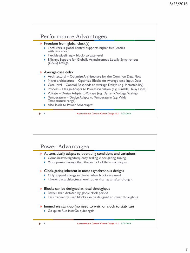
Performance Advantages Freedom from global clock(s)
Local versus global control supports higher frequencies with less effort
Flexible pipelining – block- to gate-level
Efficient Support for Globally Asynchronous Locally Synchronous (GALS) Design
Average-case delay Architectural – Optimize Architecture for the Common Data Flow
Micro-architectural – Optimize Blocks for Average-case Input Data
Gate-level – Control Responds to Average Delays (e.g. Metastability)
Process – Design Adapts to Process Variation (e.g. Tunable Delay Lines)
Voltage – Design Adapts to Voltage (e.g. Dynamic Voltage Scaling)
Temperature – Design Adapts to Temperature (e.g. Wide Temperature range)
Also leads to Power Advantages!
Power Advantages
5/25/2016Asynchronous Control Circuit Design - L114
Automatically adapts to operating conditions and variations Combines: voltage/frequency scaling, clock-gating, tuning
More power savings, than the sum of all these techniques
Clock-gating inherent in most asynchronous designs Only expend energy in blocks when blocks are used
Inherent in architectural level rather than as an after-thought
Blocks can be designed at ideal throughput Rather than dictated by global clock period
Less frequently used blocks can be designed at lower throughput
Immediate start-up (no need to wait for clock to stabilize) Go quiet; Run fast; Go quiet again

5/25/2016
8
5/25/2016Asynchronous Control Circuit Design - L115
Other Advantages
Reduced Electromagnetic Noise
No global clock
Frequency spread out much more
Co-locate with sensitive analog
Less noise - does not effect analog circuitry
Ease of Modular Composition
Reduces design complexity, cost, risk, iterations, time to market
Supports GALS design for multi-frequency disparate SoC
designs
Handshaking offers plug-and-play IP
5/25/2016Asynchronous Control Circuit Design - L116
Asynchronous Challenges (1 of 2) CAD tools
Support from major EDA companies
Cell/IP Core Libraries for Asynchronous Design Most design styles could benefit from at least a few asynchronous cells
e.g., C-elements, Mutual Exclusion Elements
Some design styles heavily rely on custom gates QDI PCHB, NCL
High-performance asynchronous design Some blocks can be 2-5x larger due to dual-rail design
May consume more peak power than desired
Low-power asynchronous design Can be slower than desired, if control overhead not managed

5/25/2016
9
Asynchronous Challenges (2 of 2)
5/25/2016Asynchronous Control Circuit Design - L117
Debug
Circuit can’t be slowed via clock to aid in debugging
…but the circuit can be single-stepped more easily!
Asynchronous test
Testers geared toward synchronous
Standards do not exist and test methodologies still evolving
Automatic test pattern generation in infancy
5/25/2016Asynchronous Control Circuit Design - L118
Asynchronous Commercialization Efforts
(1 of 2)
Fulcrum Microsystems (www.fulcrummicro.com) High-performance computing and networking markets
Founded out of Caltech in 2000, Sold to Intel in 2011
Several asynchronous products shipping, Full-custom flow still in use today
TimeLess Design Automation High-Performance ASIC Flow for Asynchronous Design
Founded out of USC in 2008
Sold to Fulcrum Microsystems in 2010
Semi-custom flow still in use today
Achronix (www.achronix.com) High-performance async FPGA core with synchronous interfaces
Founded out of Cornell research in 2006
Speedster®22i HP is shipping and includes fine-grain asynchronous pipelines

5/25/2016
10
5/25/2016Asynchronous Control Circuit Design - L119
Asynchronous Commercialization Efforts
(2 of 2)
Tiempo (www.tiempo-ic.com) IP Cores and ASIC Flow (Power/Performance Tradeoff)
Smartcards …
vSync Circuits (www.vsyncc.com) EDA and IP for Multi-Clock Domain design integration and verification
Reduced Energy Microsystems (remicro.systems) Low Power ASIC microprocessors using asynchronous resiliency
Founded in 2015 – Newest kid on the block
IBM Neuromorphic True North core based on QDI technology (EXPAND)
Several Past Start-ups Handshake Solutions,
Silistix,
Elastix, Nanochronous,
Cogency
Channel-Based Design
Top-Level View of Asynchronous Circuits
5/25/2016Asynchronous Control Circuit Design - L120

5/25/2016
11
Hardware Abstraction
Asynchronous Control Circuit Design - L121
System:
Collection of “Processes” linked by Channels
Channels pass messages with guaranteed delivery
Processes synchronize
Processes can be decomposed into smaller processes
5/25/2016
Synchronous Version
In case of edge triggered stages
During the cycle: Process
At the edge of the clock: Pass to successor
clock
Process
clock
Pass to successor
22 Asynchronous Control Circuit Design - L1 5/25/2016

5/25/2016
12
Synchronous Version
module ff(clk, left, right)
input clk;
input left;
output reg right;
always
begin
`SYNC(clk);
right = left;
end
endmodule
Central synchronizer
`SYNC(clk)
23 Asynchronous Control Circuit Design - L1 5/25/2016
Synchronous FF Stage
Abstract synchronization
`SYNC(clk)
module ff(clk, left, right)
input clk;
input left;
output reg right;
always @(posedge clk) begin
right = left;
end
endmodule
module ff(clk, left, right)
input clk;
input left;
output reg right;
always
begin
`SYNC(clk);
right = left;
end
endmodule
24 Asynchronous Control Circuit Design - L1 5/25/2016

5/25/2016
13
Asynchronous Version
module Sender(right)
output reg right;
output reg data;
always
begin
right = data;
`SYNC(right);
end
endmodule
module Receiver(left)
input left;
output reg data;
always
begin
`SYNC(left);
data= left;
end
endmodule
Distributed Synchronization
Sender
Provides data
Synchronize
Receiver
Synchronize
Samples data
Sender Receiver
25 Asynchronous Control Circuit Design - L1 5/25/2016
Asynchronous Channels
Asynchronous Control Circuit Design - L126
Channel: A bundle of wires and a protocol for
communicating data/control called a token
Data/control encoding: Dual-rail or Single-rail encoded
tells what the data is, and when it is valid
Communication protocol: Handshake over
request/acknowledgement wires
Sender Receiver
AbstractChannelFunctional
Block
5/25/2016
5/25/2016
14
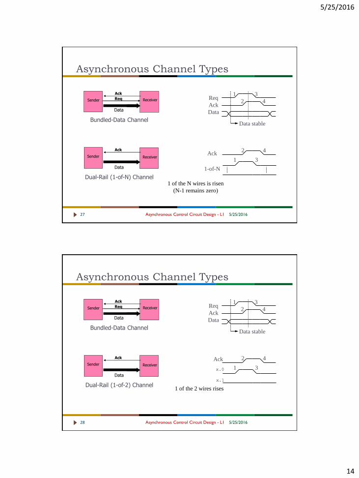
Asynchronous Channel Types
Asynchronous Control Circuit Design - L127
1 of the N wires is risen
(N-1 remains zero)
Req
Ack
Data
Data stable
1
2
3
4
1
2
3
4Ack
1-of-N
Data
Req
Ack
Bundled-Data Channel
Sender Receiver
Data
Ack
Dual-Rail (1-of-N) Channel
Sender Receiver
5/25/2016
x.1
Asynchronous Channel Types
Asynchronous Control Circuit Design - L128
1 of the 2 wires rises
Req
Ack
Data
Data stable
1
2
3
4
1
2
3
4
Data
Req
Ack
Bundled-Data Channel
Sender Receiver
Data
Ack
Dual-Rail (1-of-2) Channel
Sender Receiver
5/25/2016
Ack
x.0

5/25/2016
15
Asynchronous Design Levels of Abstraction
5/25/2016Asynchronous Control Circuit Design - L129
System-level Optimization
DatapathCircuits
Control Circuits
Control Circuits –Implementing Channel Protocols Latch Opening
and Closing
Data Token
Processing
Data,
control
interaction
Throughput, Latency Optimization Hiding
handshake overhead
Retiming, etc.
Asynchronous Design Levels
5/25/2016Asynchronous Control Circuit Design - L130
Block-Level Design – Micro-architectural Level Control Circuits – Implementing Channel Protocols
Handshake-based Token Movement, i.e. H/S Protocol Implementation
Latch Opening and Closing
Synchronization of Multiple Requests and Acknowledgments, … etc.
Datapath Circuits – Data Token Processing Asynchronous Implementation of Combinational Clouds and Interaction with the
H/S-based Control Circuits Bundled-data, i.e. delay-element based
Data-Dependent Latency – Multiplexed Delay, based on Operands/Operation
Dual-Rail/Indicating Logic (Encoded)
System-level Optimization –Architecture Level Optimizing Token Cycle Time, Throughput (Tokens/sec)
Trading-off Token Latency for Token Throughput
Hiding Handshake Delays to achieve comparable cycle time to sync.
Retiming, i.e. Splitting Combinational Logic, adding Token Buffers (Latches)

5/25/2016
16
Logic Hazards (Glitches)
Asynchronous Control Circuit Design - L131
Synchronous Circuits
Glitches tolerated because outputs sampled only after signals settle
Clocking constraints
Clock edge occurs only after data
settles
Limits clock frequency
Asynchronous Circuits
Control circuits
Avoided completely
Hazard-free logic synthesis techniques
Datapath (Either)
Outputs sampled after signal settles OR
Avoided completely
5/25/2016
Asynchronous Circuits - Classes
5/25/2016Asynchronous Control Circuit Design - L132
Timing Model (or Class) is used to define specific timing
assumptions with respect to correct circuit operation
DI
Arbitrary gate and wire delays (unbounded)
QDI
DI except for Isochronic Forks
No need to acknowledge fanouts
SI (Muller) circuits
Arbitrary gate delay no wire delay
Only applicable to small-scale control circuits
Fundamental Mode (Huffman) circuits
Outputs and Local State (internal) stabilize
before a new input change from the circuit’s environment
QDI
SI
Fundamental Mode
Timing Assumptions
Pyramid

5/25/2016
17
2-Phase Bundled-Data
Asynchronous Control Circuit Design - L133 5/25/2016
Data
Req
Ack
Bundled-Data Channel
Sender Receiver
Two-phase Bundled-Data Protocol Both rising and falling transitions on Req
Means new data are available
Both rising and falling transitions on Ack Means data have been acknowledged
Sometimes called transition signaling It is the transition that is meaningful (stateful), not the level values
2nd data1st data
Req
Ack
Data
Push Channels Pull Channels shortly
1-of-N Protocols
Asynchronous Control Circuit Design - L134
Data
Ack
Dual-Rail (1-of-N) Channel
Sender Receiver
5/25/2016
Dual-Rail
4 phase
2 wires per bit
1-of-4
4 phase
4 wires per 2 bits
Data_0
Data_1
Ack
1st token = 0 2
nd token = 1
Data_0
Data_3
Ack
1st token = 1 2
nd token = 3
Data_1
Data_2
(a)
(b)

5/25/2016
18
(a)
(c)
(b)
1st data 2
nd
Req
Ack
Late
Req
Early 1st data
Ack
2nd
data
0th
1st data 2
nd Data
Ack
0th
Req
Broad
Pull Channels
5/25/2016Asynchronous Control Circuit Design - L135
Early: Data stable after Ack+
Data stable until Req-
Sender
Request
Acknowledge
Single-Rail Data
Receiver
Late: Data stable after Ack-
Data stable until Req+
Broad: Data stable after Ack+
Data stable until Req-
Abstract Channel Diagrams
Asynchronous Control Circuit Design - L136
(a)
(b)
(c)
Handshaking details omitted
5/25/2016
Synchronization channel –no data attached/bundled No data – Control only
Active on right side
Pull Channel
Push Channel

5/25/2016
19
Enclosed Handshaking
B completes handshake with C before starting handshake with D
Operation associated with C occurs before operation associated with D
B can enclose both handshakes in handshake with A
Completion of handshake with A is acknowledgement that the tasks of C and D are done
Pipelining Handshake
B overlaps handshake with C and handshake with A
Creates pipeline behavior
Tokens flow on both channels
Increases throughput
Sequencing and Concurrency
Asynchronous Control Circuit Design - L137
BCD
A
A B C
5/25/2016
A
B
C
D
Token Buffer Pipelines
Pipelining Data Tokens
5/25/2016Asynchronous Control Circuit Design - L138

5/25/2016
20
Pipelined Handshaking
Asynchronous Control Circuit Design - L139
Bit
GenBUF BUF BUF
Bit
BucketC0 C1 C2 C3
5/25/2016
Pipeline handshaking enables multiple tokens to exist in pipeline Each token represents intermediate result of different problem instance
Increases throughput of system
No tokens lost despite relative speed of stages – has implicit flow control
Two types Full buffers can support distinct tokens on inputs/output channels
Half buffers cannot support distinct tokens on inputs/outputs N-stage pipeline of half-buffers can support a maximum of N/2 tokens
Bit
GenBUF BUF BUF
Bit
BucketC0 C1 C2 C3
Full-Buffer Handshaking
Asynchronous Control Circuit Design - L140
Handshaking assuming Bit Bucket is Stalled
5/25/2016
Pipeline
can store
tokens at
every
buffer
T1 T2 T3 T4
C2req
C2ack
C3req
C3ack
C0req
C0ack
C1req
C1ack
T1 T2
T1
T3
T1
T2

5/25/2016
21
C2req
C2ack
C3req
C3ack
C0req
C0ack
C1req
C1ack
T1
T1
T1
T1
T2
T2
Handshaking assuming Bit
Bucket is Stalled
Constraint that leads
to a half-buffer:
output channel must
be acknowledged
before input channel
completes handshake
e.g., c1ack+
before c0ack-
Pipeline can store
tokens at every other
buffer
Bit
GenBUF BUF BUF
Bit
BucketC0 C1 C2 C3
Half-Buffer Handshaking
Asynchronous Control Circuit Design - L141 5/25/2016
Conditional and Non-Linear Pipeines
Asynchronous Control Circuit Design - L142
MERGE Wait for token on S.
Depending on value, wait for token on either A or B and send onto O
SPLIT Wait for token on S and A.
Dependent upon value of S, send copy of token on A to O1 or O2
(a) (b)
ME
RG
E
A
B
O
S
SP
LIT
O1
O2
S
A
5/25/2016

5/25/2016
22
Areq
Aack
Breq
Back
S0
Sack
S1
Oreq
Oack
Timing Diagram of Merge
Asynchronous Control Circuit Design - L143 5/25/2016
Assumptions (in this example) Full-buffer Two-phase Handshaking
dual-rail select signal
Functionality – Handshake MUX Token on A consumed first
After token on S = 0
i.e., S0 changes
Token on B stalled until consumed second After token on S = 1
i.e., Once S1 changes
Result: two tokens on O First = Oreq+
Second = Oreq-
Send and Receive Cells
SEND
Always receive on L and E.
Conditionally send on R if E==1.
RECV
Always receive on E and send on R.
Conditionally receive on L if E==1.
5/25/2016Asynchronous Control Circuit Design - L144
REC
VL R
E
SENDL R
E

5/25/2016
23
Asynchronous Pipelines
Dynamic behavior is very different from synchronous design
5/25/2016Asynchronous Control Circuit Design - L145
Synchronous vs. Asynchronous Pipelines
5/25/2016Asynchronous Control Circuit Design - L146
Intuitive Understanding of the Differences

5/25/2016
24
Datapath
Example
5/25/2016Asynchronous Control Circuit Design - L147
FF Datapath: each
FF is 2 Latches
5/25/2016Asynchronous Control Circuit Design - L148

5/25/2016
25
Synchronous vs. Asynchronous
5/25/2016Asynchronous Control Circuit Design - L149
Tokens represent Data
Data Tokens
We now compare the Synchronous and Asynchronous
Data Flows in the simplest version of this datapath
Synchronous version first…
Synchronous Token
Movement
5/25/2016Asynchronous Control Circuit Design - L150

5/25/2016
26
Synchronous Token
Movement
5/25/2016Asynchronous Control Circuit Design - L151
Synchronous Token
Movement
5/25/2016Asynchronous Control Circuit Design - L152

5/25/2016
27
Synchronous Token
Movement
5/25/2016Asynchronous Control Circuit Design - L153
Synchronous Token
Movement
5/25/2016Asynchronous Control Circuit Design - L154

5/25/2016
28
Synchronous Token
Movement
5/25/2016Asynchronous Control Circuit Design - L155
Synchronous Token
Movement
5/25/2016Asynchronous Control Circuit Design - L156

5/25/2016
29
Synchronous Token
Movement
5/25/2016Asynchronous Control Circuit Design - L157
Synchronous Token
Movement
5/25/2016Asynchronous Control Circuit Design - L158

5/25/2016
30
Synchronous Token
Movement
5/25/2016Asynchronous Control Circuit Design - L159
Synchronous Token Movement
5/25/2016Asynchronous Control Circuit Design - L160
Tokens are always separated by empty latches
Aka “Bubbles”
Latency in strongly dependent on # of clock cycles
Pipeline delays result in cycle-based Latency increase
Now, let’s look at the Asynchronous version…

5/25/2016
31
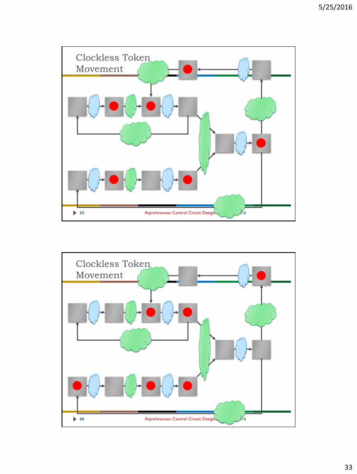
Clockless Token
Movement
5/25/2016Asynchronous Control Circuit Design - L161
Clockless Token
Movement
5/25/2016Asynchronous Control Circuit Design - L162
+

5/25/2016
32
Clockless Token
Movement
5/25/2016Asynchronous Control Circuit Design - L163
Clockless Token
Movement
5/25/2016Asynchronous Control Circuit Design - L164
5/25/2016
33
Clockless Token
Movement
5/25/2016Asynchronous Control Circuit Design - L165
Clockless Token
Movement
5/25/2016Asynchronous Control Circuit Design - L166

5/25/2016
34
Clockless Token
Movement
5/25/2016Asynchronous Control Circuit Design - L167
Clockless Token
Movement
5/25/2016Asynchronous Control Circuit Design - L168

5/25/2016
35
Clockless Token
Movement
5/25/2016Asynchronous Control Circuit Design - L169
Clockless Token
Movement
5/25/2016Asynchronous Control Circuit Design - L170

5/25/2016
36
Clockless Token
Movement
5/25/2016Asynchronous Control Circuit Design - L171
Clockless Token
Movement
5/25/2016Asynchronous Control Circuit Design - L172
5/25/2016
37
Asynchronous Token Movement
5/25/2016Asynchronous Control Circuit Design - L173
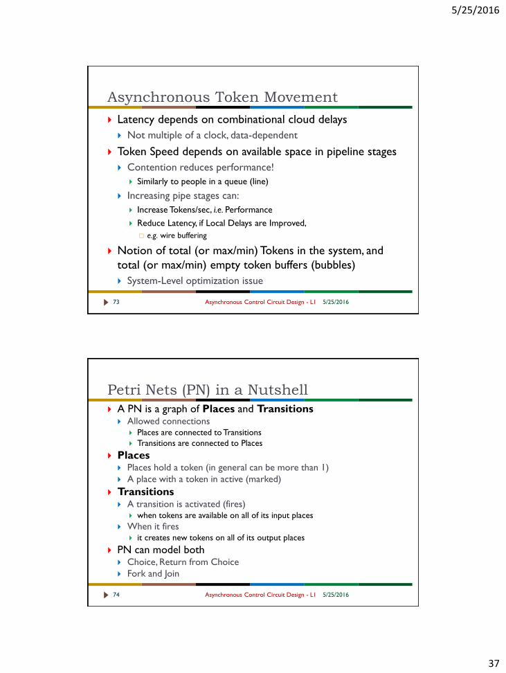
Latency depends on combinational cloud delays
Not multiple of a clock, data-dependent
Token Speed depends on available space in pipeline stages
Contention reduces performance!
Similarly to people in a queue (line)
Increasing pipe stages can:
Increase Tokens/sec, i.e. Performance
Reduce Latency, if Local Delays are Improved,
e.g. wire buffering
Notion of total (or max/min) Tokens in the system, and
total (or max/min) empty token buffers (bubbles)
System-Level optimization issue
Petri Nets (PN) in a Nutshell
5/25/2016Asynchronous Control Circuit Design - L174
A PN is a graph of Places and Transitions Allowed connections
Places are connected to Transitions
Transitions are connected to Places
Places Places hold a token (in general can be more than 1)
A place with a token in active (marked)
Transitions A transition is activated (fires)
when tokens are available on all of its input places
When it fires it creates new tokens on all of its output places
PN can model both Choice, Return from Choice
Fork and Join

5/25/2016
38
High-Level Asynchronous Pipeline:
PTnet Models
5/25/2016Asynchronous Control Circuit Design - L175
Full Buffer High-Level Model
Used to analyze and optimize Throughput and Latency:
High-Level Asynchronous Pipeline
PTnet Models
5/25/2016Asynchronous Control Circuit Design - L176
Full Buffer and Half Buffer High-Level Models
Used to analyze and optimize Throughput and Latency:

5/25/2016
39
Dynamic Pipeline Behavior
Asynchronous Control Circuit Design - L1
Cycle Time T = FL + BL (simplest case)
Latency input to output delay = N * FL
Throughput # of tokens flowing per unit time, generally = 1/T = 1/(FL + BL)
Depends on throughput of sender/receiver
Static Slack or Static Token Occupancy Maximum token capacity of the pipeline
Spread distance between successive tokens in an optimally-filled pipeline
token distance travelled for 1 T = (FL + BL)/FL
Dynamic Slack or Dynamic Occupancy Average token capacity in the pipeline at optimal throughput
N*1/Spread = (N*FL)/(FL + BL)
5/25/201677
Dynamic Pipeline Behavior
Asynchronous Control Circuit Design - L1
Cycle Time
T = FL + BL (simplest case)
Latency
input to output delay = N * FL
Throughput
# of tokens flowing per unit time, generally = 1/T = 1/(FL + BL)
Depends on throughput of sender/receiver
Static Slack or Static Token Occupancy
Maximum token capacity of the pipeline
Dynamic Slack or Dynamic Occupancy
Average token capacity in the pipeline at optimal throughput
N*1/Spread = (N*FL)/(FL + BL)
5/25/201678

5/25/2016
40
Dynamic Occupancy, Throughput
Dynamic Slack or Dynamic Occupancy Formula for N buffers:
Assumptions:
Tokens not stalled by buffers or Bit Bucket resetting
Tokens inserted at rate of local cycle time (FL + BL)
Tokens consumed at rate of local cycle time
peak
throughput
bubble
limited
region
token
limited
region
dynamic
slack
static
slack
# tokens
throughput
Bit
GenBUF BUF BUF
Bit
BucketC0 C1 C2 C3
FL
BL
N
BLFL
FLN
1
*
Asynchronous Control Circuit Design - L1
(average)
Peak Throughput
= 1/(FL + BL)
5/25/201679
Throughput vs. Tokens Graph
Throughput is zero When no tokens in pipe
When pipeline is full of tokens
Peak throughput in-between Token limited region
Faster Bit Gen improves throughput
Bubble limited region
Faster Bit Bucket improves performance
peak
throughput
bubble
limited
region
token
limited
region
dynamic
slack
static
slack
# tokens
throughput
Bit
GenBUF BUF BUF
Bit
BucketC0 C1 C2 C3
Asynchronous Control Circuit Design - L1 5/25/201680
N
FL
1
N
BL
1

5/25/2016
41
Example: Pipeline Performance
Bit
GenBUF BUF BUF
Bit
BucketC0 C1 C2 C31
t=0t=2t=8t=4t=6t=18t=10
2
t=12t=14t=16
34
t=20t=22t=24
5
t=0: Token 1 generated
t=6: Token 2 generated
t=12: Token 3 generated
t=18: Token 4 generated
t=24: Token 5 generated
Asynchronous Control Circuit Design - L1 5/25/201681
Slow left environment
Bit Gen: LCT = 6
Buffer: FL=2, BL=2
Bit Bucket: LCT = 2
Example: Pipeline Performance
Bit
GenBUF BUF BUF
Bit
BucketC0 C1 C2 C31
t=0t=6t=2t=4t=8t=10t=12t=14
23
t=16
45
t=18t=20
t=6: Token 1 consumed
t=12: Token 2 consumed
t=18: Token 3 consumed
t=24
t=24: Token 4 consumed
t=22
Asynchronous Control Circuit Design - L1 5/25/201682
Slow right environment
Bit Gen: LCT = 2
Buffer: FL=2, BL=2
Bit Bucket: LCT = 6

5/25/2016
42
Concrete Example: 3-stage Pipeline
Bit
GenBUF BUF BUF
Bit
BucketC0 C1 C2 C3
1/6
1/4
3/2 3
# tokens
throughput
Buffer: FL=2, BL=2
Asynchronous Control Circuit Design - L1 5/25/201683
More Complex Example: Pipeline
Performance
5/25/2016Asynchronous Control Circuit Design - L184
What is the impact of fork/join on asynchronous
pipelines?
Assume FL = 1, BL = 1 4, 3 Fork Join

5/25/2016
43
More Complex Example: Pipeline
Performance
5/25/2016Asynchronous Control Circuit Design - L185
What is the impact of fork/join on asynchronous
pipelines?
Assume FL = 1, BL = 1 4, 2 Fork Join
More Complex Example: Pipeline
Performance
5/25/2016Asynchronous Control Circuit Design - L186
What is the impact of fork/join on asynchronous
pipelines?
Assume FL = 1, BL = 1 4, 1 Fork Join

5/25/2016
44
DEMUXA,B
op
Add/Sub
Mult
MUXD
+
0
+ +
D
Stalled!
P. A. Beerel et. al. , “Slack matching asynchronous designs,” ASYNC’06
D
Stalled!
Represents up to 30% of area and power
5/25/2016Asynchronous Control Circuit Design - L187
Key to High Performance –
Slack Matching
The Slack Matching Problem: Add minimum number of pipeline buffers to the circuit to meet a target T
This problem is unique to Asynchronous Design Unfortunately, often yields significant Area and Power Overhead!
Latch Control Circuits
Basic Example of Latch Control
5/25/2016Asynchronous Control Circuit Design - L188

5/25/2016
45
Bundled-Data Control Circuits –
Basic Latch Control
5/25/2016Asynchronous Control Circuit Design - L189
Latch
Controller
Left Hand Side
Channel (H/S)
Right Hand Side
Channel (H/S)
Latch
provide latch EN
enable signal
Latch Open/Close
Logic
LHS/RHS Handshakes
indicate Channel State
C Gate – PN to STG Conversion
5/25/2016Asynchronous Control Circuit Design - L190
a+ b+
c+
a- b-
c-
a+ b+
c+
a- b-
c-
keep transitions
keep tokens
hide places

5/25/2016
46
Condition 1: Latch Should Not Open until
Successor Latch has Captured Data
5/25/2016Asynchronous Control Circuit Design - L191
A B C D0 0 0 0
A+ B- C+ D-
A- B+ C- D+
A+ B- C+ D-
A- B+ C- D+
A+ B- C+ D-
Condition 1: Latch Should Not Open until
Successor Latch has Captured Data
5/25/2016Asynchronous Control Circuit Design - L192
A B C D0 0 0 0
A+ B- C+ D-
A- B+ C- D+
A+ B- C+ D-
A- B+ C- D+
A+ B- C+ D-

5/25/2016
47
Condition 1: Latch Should Not Open until
Successor Latch has Captured Data
5/25/2016Asynchronous Control Circuit Design - L193
A B C D0 0 0 0
A+ B- C+ D-
A- B+ C- D+
A+ B- C+ D-
A- B+ C- D+
A+ B- C+ D-
Condition 1: Latch Should Not Open until
Successor Latch has Captured Data
5/25/2016Asynchronous Control Circuit Design - L194
A B C D0 0 0 0
A+ B- C+ D-
A- B+ C- D+
A+ B- C+ D-
A- B+ C- D+
A+ B- C+ D-
5/25/2016
48
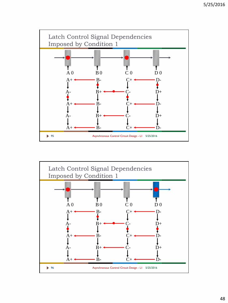
Latch Control Signal Dependencies
Imposed by Condition 1
5/25/2016Asynchronous Control Circuit Design - L195
A B C D
A+ B- C+ D-
A- B+ C- D+
A+ B- C+ D-
A- B+ C- D+
A+ B- C+ D-
0 0 0 0
Latch Control Signal Dependencies
Imposed by Condition 1
5/25/2016Asynchronous Control Circuit Design - L196
A B C D
A+ B- C+ D-
A- B+ C- D+
A+ B- C+ D-
A- B+ C- D+
A+ B- C+ D-
0 0 0 0

5/25/2016
49
Latch Control Signal Dependencies
Imposed by Condition 1
5/25/2016Asynchronous Control Circuit Design - L197
A B C D0 0 0 0
A+ B- C+ D-
A- B+ C- D+
A+ B- C+ D-
A- B+ C- D+
A+ B- C+ D-
Condition 2: Latch Should Not Close until
Captured Data from Predecessor
5/25/2016Asynchronous Control Circuit Design - L198
A B C D0 0 0 0
A+ B- C+ D-
A- B+ C- D+
A+ B- C+ D-
A- B+ C- D+
A+ B- C+ D-

5/25/2016
50
Condition 2: Latch Should Not Close until
Captured Data from Predecessor
5/25/2016Asynchronous Control Circuit Design - L199
A B C D0 0 0 0
A+ B- C+ D-
A- B+ C- D+
A+ B- C+ D-
A- B+ C- D+
A+ B- C+ D-
Condition 2: Latch Should Not Close until
Captured Data from Predecessor
5/25/2016Asynchronous Control Circuit Design - L1100
A B C D0 0 0 0
A+ B- C+ D-
A- B+ C- D+
A+ B- C+ D-
A- B+ C- D+
A+ B- C+ D-

5/25/2016
51
Condition 2: Latch Should Not Close until
Captured Data from Predecessor
5/25/2016Asynchronous Control Circuit Design - L1101
A B C D0 0 0 0
A+ B- C+ D-
A- B+ C- D+
A+ B- C+ D-
A- B+ C- D+
A+ B- C+ D-
Latch Control Signal Dependencies
Imposed by Conditions 1 and 2
5/25/2016Asynchronous Control Circuit Design - L1102
A B C D0 0 0 0
A+ B- C+ D-
A- B+ C- D+
A+ B- C+ D-
A- B+ C- D+
A+ B- C+ D-

5/25/2016
52
Folded Latch Control Signal Dependencies
Imposed by Conditions 1 and 2
5/25/2016Asynchronous Control Circuit Design - L1103
A B C D
Latch Control Signal
Graph Dependencies
can also be visualized
in the Time Domain
A
B
A+ B+ C+ D+
A- B- C- D-
Formal Models For Asynchronous Control
Circuit Design
5/25/2016Asynchronous Control Circuit Design - L1104
The graph model examples are really simplified PN
PN is Place, Transition Net (invented by Petri)
Represent Dependencies between signal transitions
Causality
Can Represent Choice
Multiple Signals (Places really) are active at one time
Represent Concurrency
A PN is really a set of Multiple, Interacting FSMs all
integrated and hidden within a single Graph!
Compact and Convenient
Ideal for Static Verification