Embed Size (px)
Citation preview
Counters and State Machine Design 1 November 2005
ENGI 251/ELEC 241 1
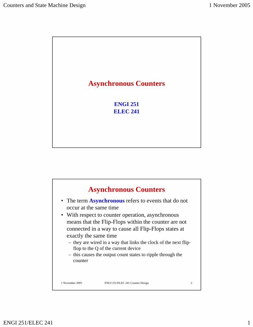
Asynchronous Counters
ENGI 251ELEC 241
1 November 2005 ENGI 251/ELEC 241 Counter Design 2
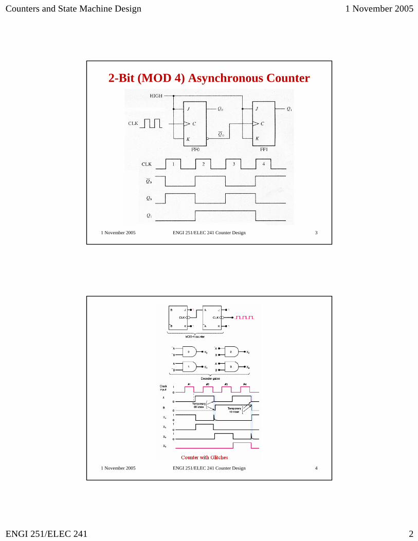
Asynchronous Counters• The term Asynchronous refers to events that do not
occur at the same time• With respect to counter operation, asynchronous
means that the Flip-Flops within the counter are not connected in a way to cause all Flip-Flops states at exactly the same time– they are wired in a way that links the clock of the next flip-
flop to the Q of the current device– this causes the output count states to ripple through the
counter
Counters and State Machine Design 1 November 2005
ENGI 251/ELEC 241 2
1 November 2005 ENGI 251/ELEC 241 Counter Design 3
2-Bit (MOD 4) Asynchronous Counter
1 November 2005 ENGI 251/ELEC 241 Counter Design 4
Counters and State Machine Design 1 November 2005
ENGI 251/ELEC 241 3
1 November 2005 ENGI 251/ELEC 241 Counter Design 5
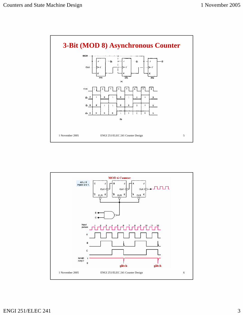
3-Bit (MOD 8) Asynchronous Counter
1 November 2005 ENGI 251/ELEC 241 Counter Design 6
Counters and State Machine Design 1 November 2005
ENGI 251/ELEC 241 4
1 November 2005 ENGI 251/ELEC 241 Counter Design 7
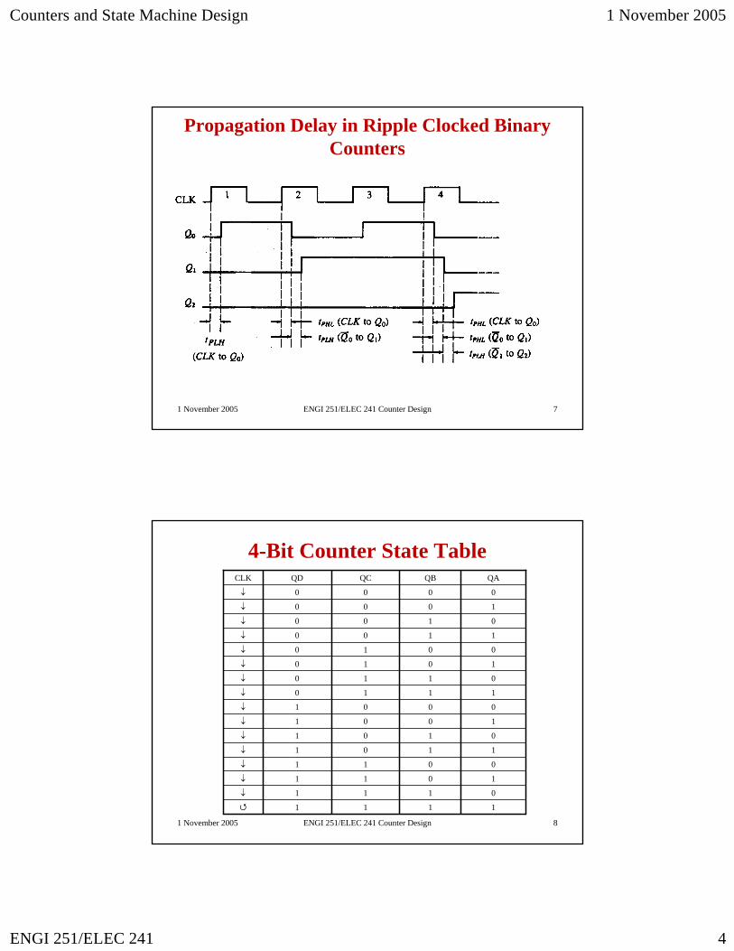
Propagation Delay in Ripple Clocked Binary Counters
1 November 2005 ENGI 251/ELEC 241 Counter Design 8
4-Bit Counter State Table
↓
↓
↓
↓
↓
↓
↓
↓
↓
↓
↓
↓
↓
↓
↓
CLK
1
1
1
1
1
1
1
1
0
0
0
0
0
0
0
0
QD
1
1
1
1
0
0
0
0
1
1
1
1
0
0
0
0
QC
1
1
0
0
1
1
0
0
1
1
0
0
1
1
0
0
QB
1
0
1
0
1
0
1
0
1
0
1
0
1
0
1
0
QA
Counters and State Machine Design 1 November 2005
ENGI 251/ELEC 241 5
1 November 2005 ENGI 251/ELEC 241 Counter Design 9
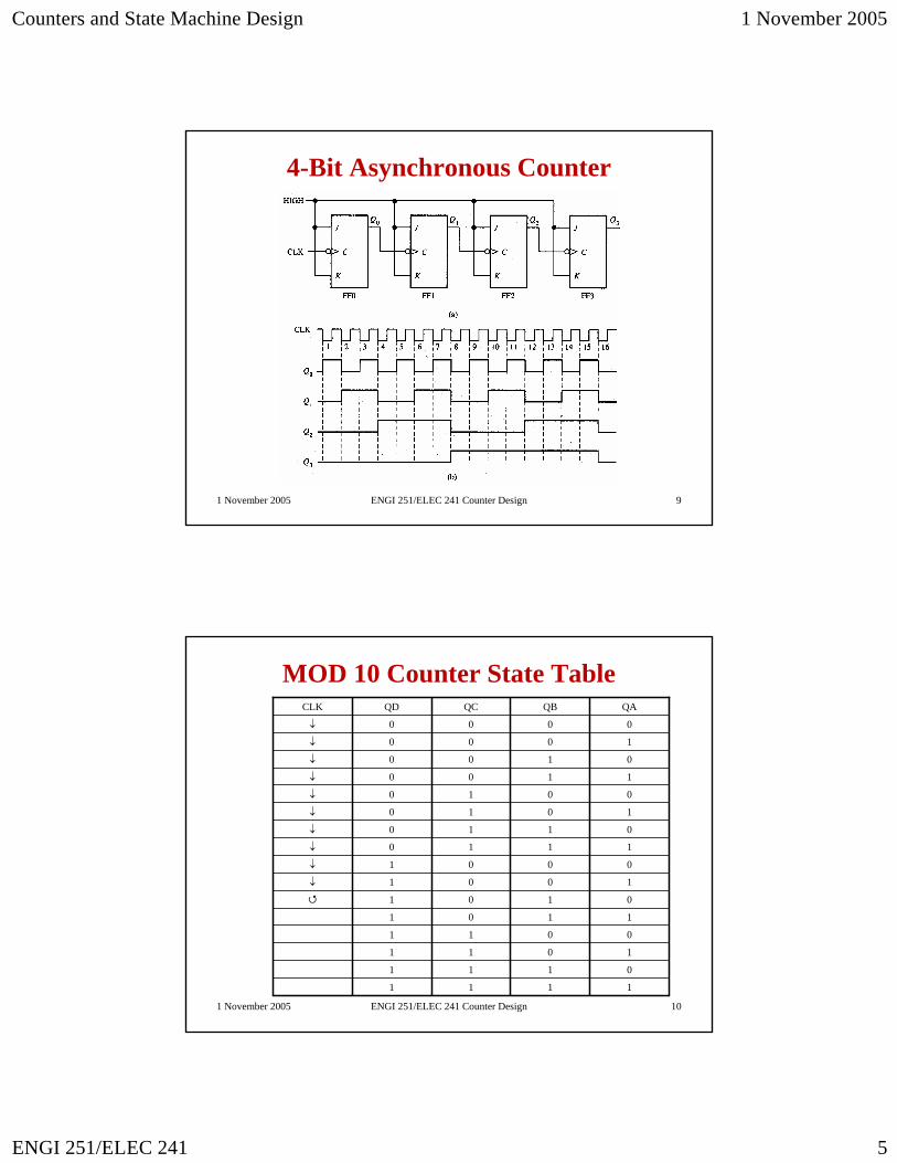
4-Bit Asynchronous Counter
1 November 2005 ENGI 251/ELEC 241 Counter Design 10
MOD 10 Counter State Table
↓
↓
↓
↓
↓
↓
↓
↓
↓
↓
CLK
1
1
1
1
1
1
1
1
0
0
0
0
0
0
0
0
QD
1
1
1
1
0
0
0
0
1
1
1
1
0
0
0
0
QC
1
1
0
0
1
1
0
0
1
1
0
0
1
1
0
0
QB
1
0
1
0
1
0
1
0
1
0
1
0
1
0
1
0
QA
Counters and State Machine Design 1 November 2005
ENGI 251/ELEC 241 6
1 November 2005 ENGI 251/ELEC 241 Counter Design 11
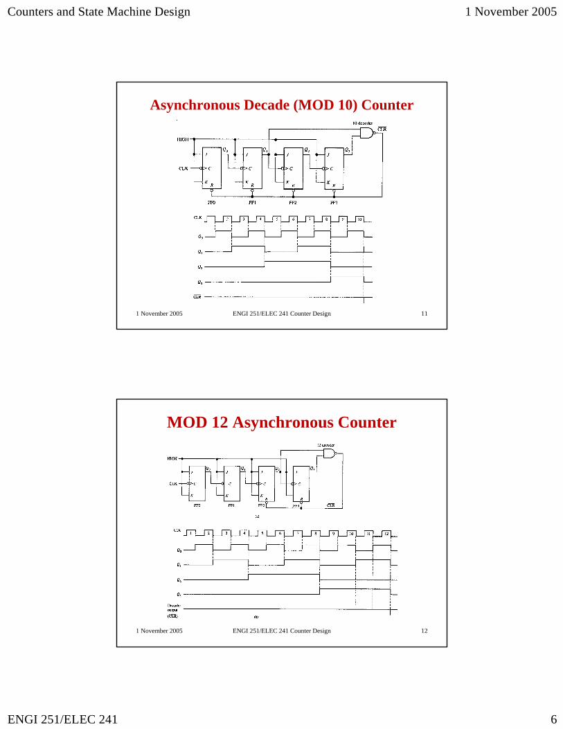
Asynchronous Decade (MOD 10) Counter
1 November 2005 ENGI 251/ELEC 241 Counter Design 12
MOD 12 Asynchronous Counter
Counters and State Machine Design 1 November 2005
ENGI 251/ELEC 241 7
1 November 2005 ENGI 251/ELEC 241 Counter Design 13
1 November 2005 ENGI 251/ELEC 241 Counter Design 14
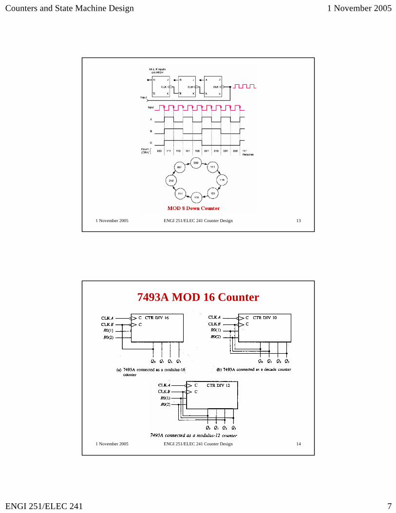
7493A MOD 16 Counter
Counters and State Machine Design 1 November 2005
ENGI 251/ELEC 241 8
Synchronous Counters
ENGI 251ELEC 241
1 November 2005 ENGI 251/ELEC 241 Counter Design 16
Synchronous Counters• The term synchronous refers to events that do occur
simultaneously– In communications, both ends must be connected –
telephone call• with respect to counter operation, synchronous means
that the counter is connected such that all the Flip-Flops change at the same time– they are wired in a way that links all the flip-flop clock
inputs together– this causes the output count states to change at the same
time– There is a propagation delay, but they are typically very
close in similar devices
Counters and State Machine Design 1 November 2005
ENGI 251/ELEC 241 9
1 November 2005 ENGI 251/ELEC 241 Counter Design 17
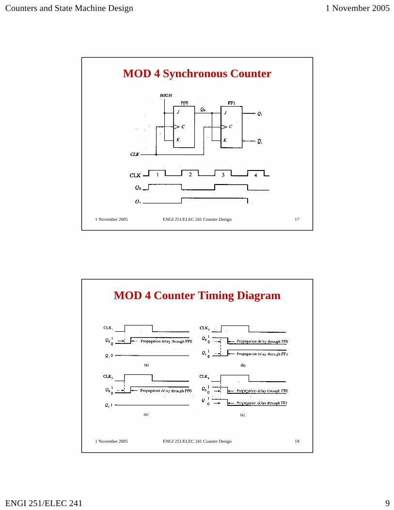
MOD 4 Synchronous Counter
1 November 2005 ENGI 251/ELEC 241 Counter Design 18
MOD 4 Counter Timing Diagram
Counters and State Machine Design 1 November 2005
ENGI 251/ELEC 241 10
1 November 2005 ENGI 251/ELEC 241 Counter Design 19
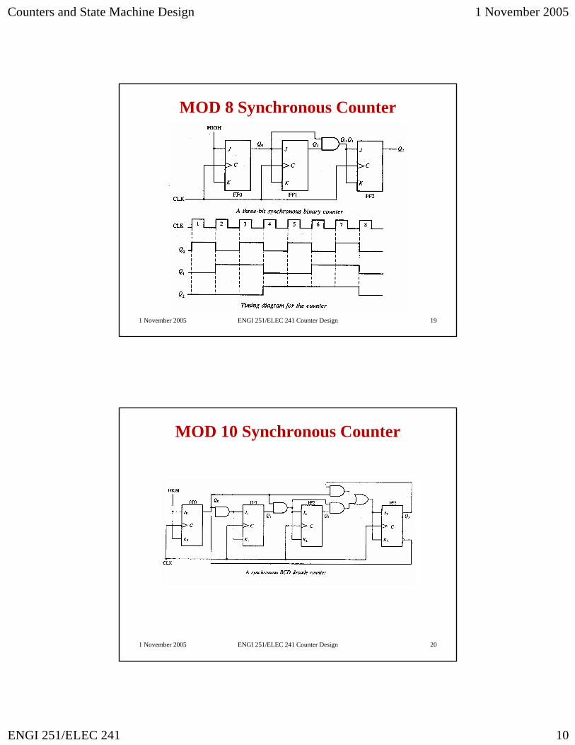
MOD 8 Synchronous Counter
1 November 2005 ENGI 251/ELEC 241 Counter Design 20
MOD 10 Synchronous Counter
Counters and State Machine Design 1 November 2005
ENGI 251/ELEC 241 11
1 November 2005 ENGI 251/ELEC 241 Counter Design 21
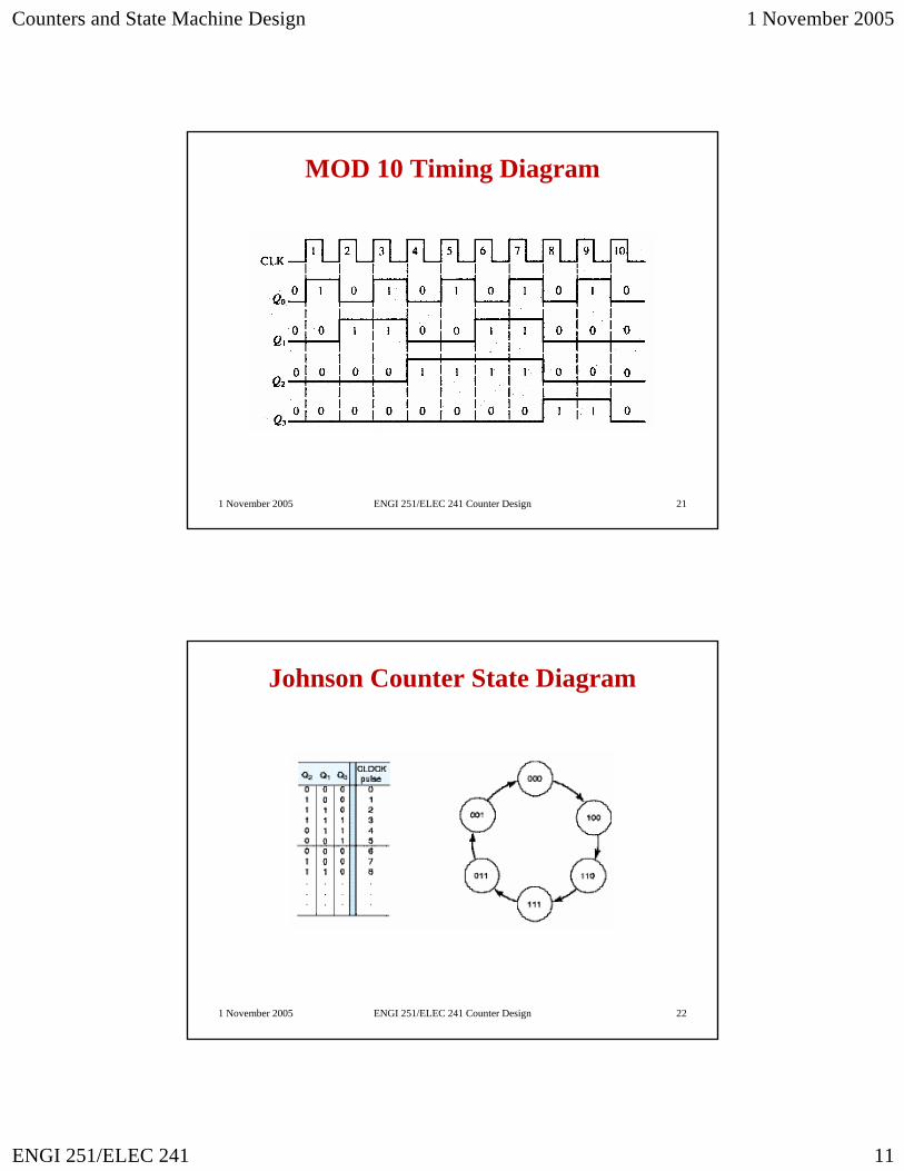
MOD 10 Timing Diagram
1 November 2005 ENGI 251/ELEC 241 Counter Design 22
Johnson Counter State Diagram
Counters and State Machine Design 1 November 2005
ENGI 251/ELEC 241 12
1 November 2005 ENGI 251/ELEC 241 Counter Design 23
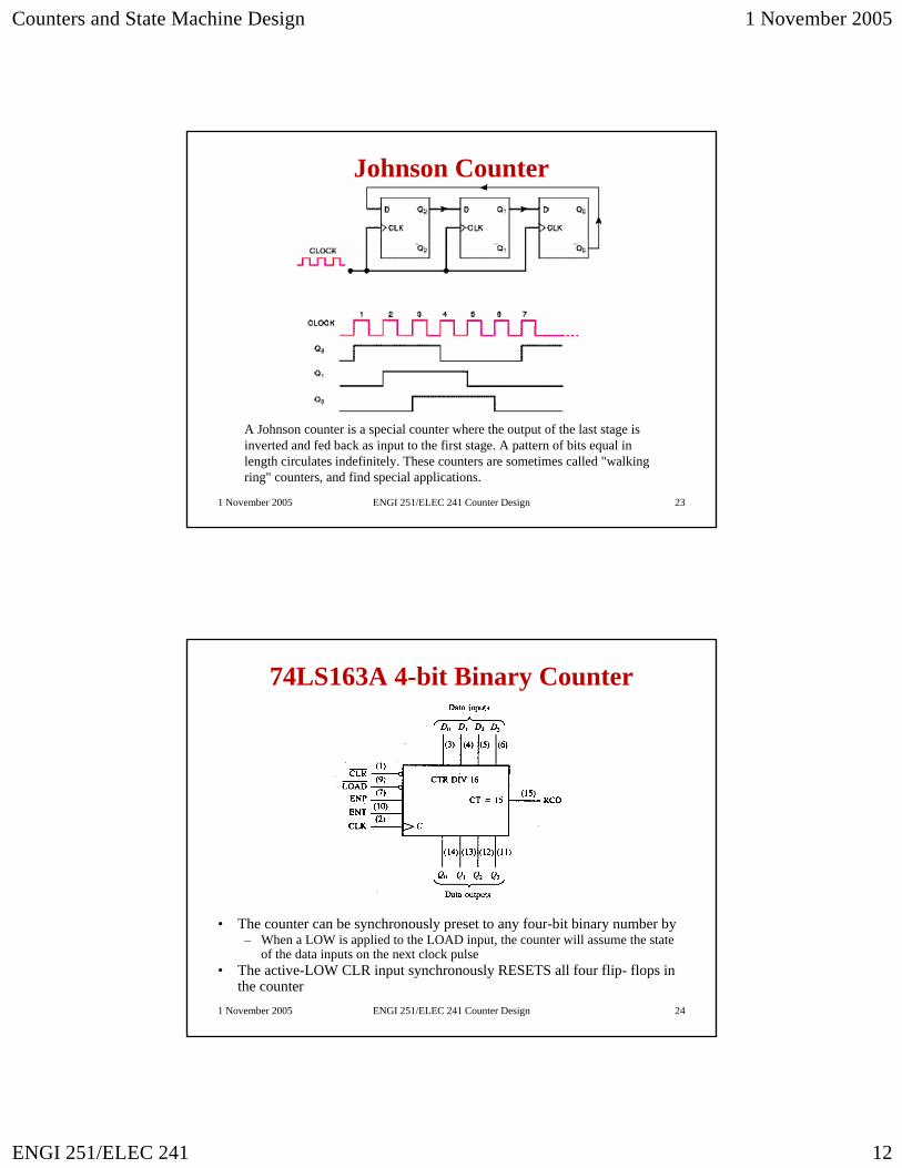
Johnson Counter
A Johnson counter is a special counter where the output of the last stage is inverted and fed back as input to the first stage. A pattern of bits equal in length circulates indefinitely. These counters are sometimes called "walking ring" counters, and find special applications.
1 November 2005 ENGI 251/ELEC 241 Counter Design 24
74LS163A 4-bit Binary Counter
• The counter can be synchronously preset to any four-bit binary number by – When a LOW is applied to the LOAD input, the counter will assume the state
of the data inputs on the next clock pulse• The active-LOW CLR input synchronously RESETS all four flip- flops in
the counter
Counters and State Machine Design 1 November 2005
ENGI 251/ELEC 241 13
1 November 2005 ENGI 251/ELEC 241 Counter Design 25
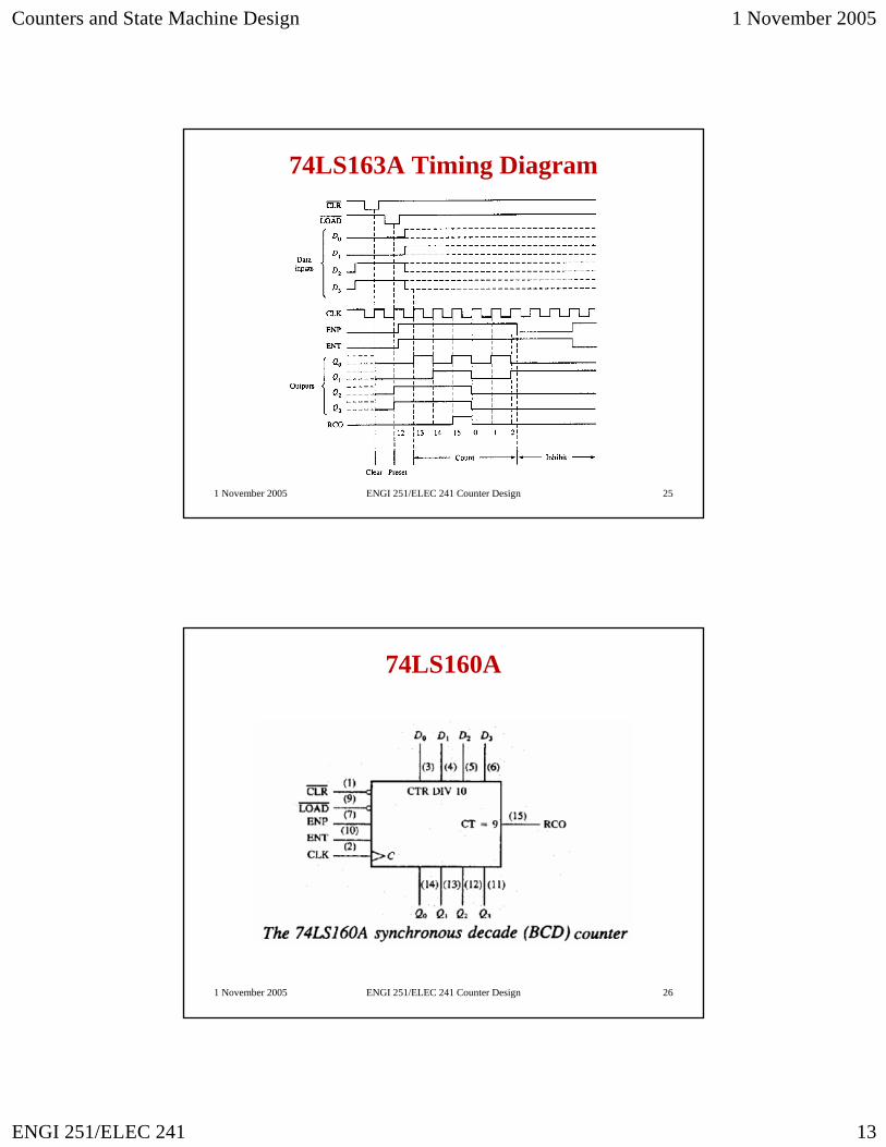
74LS163A Timing Diagram
1 November 2005 ENGI 251/ELEC 241 Counter Design 26
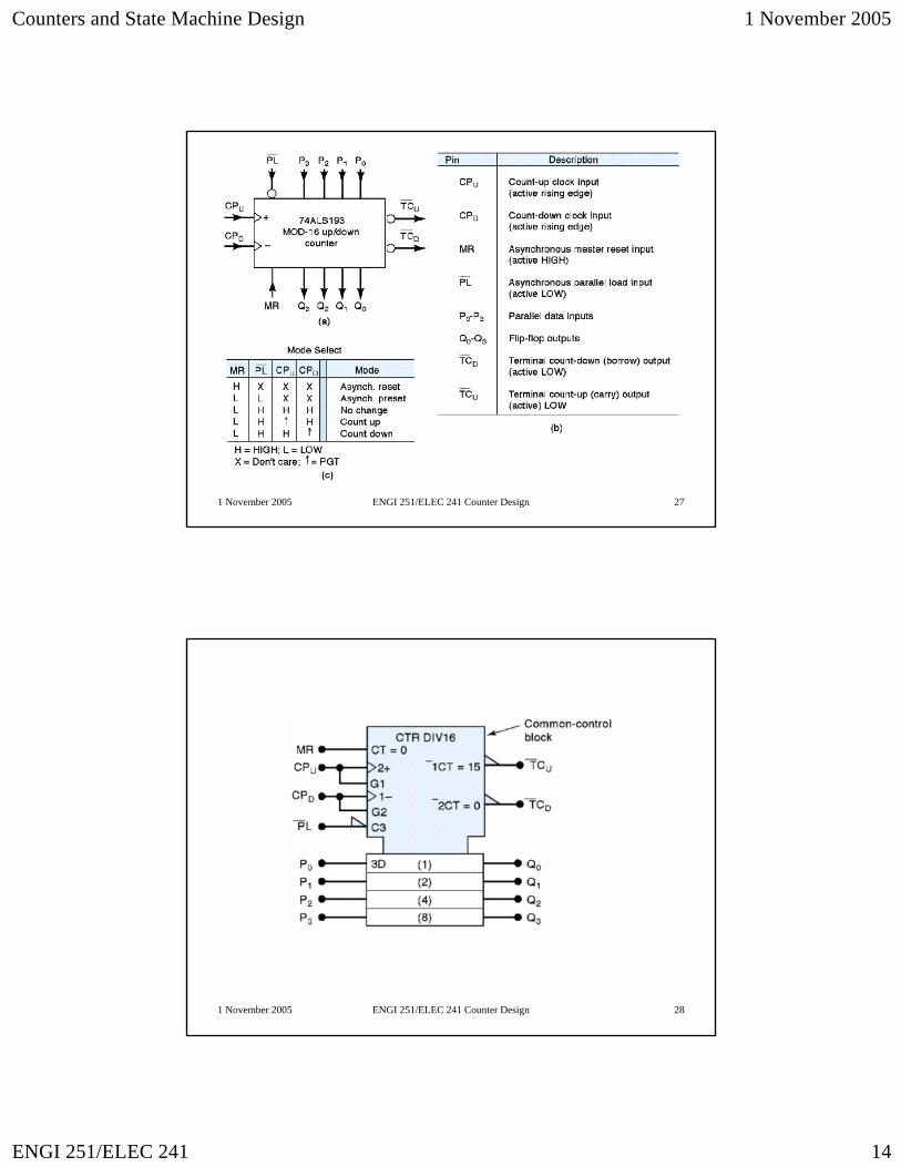
74LS160A
Counters and State Machine Design 1 November 2005
ENGI 251/ELEC 241 14
1 November 2005 ENGI 251/ELEC 241 Counter Design 27
1 November 2005 ENGI 251/ELEC 241 Counter Design 28
Counters and State Machine Design 1 November 2005
ENGI 251/ELEC 241 15
1 November 2005 ENGI 251/ELEC 241 Counter Design 29
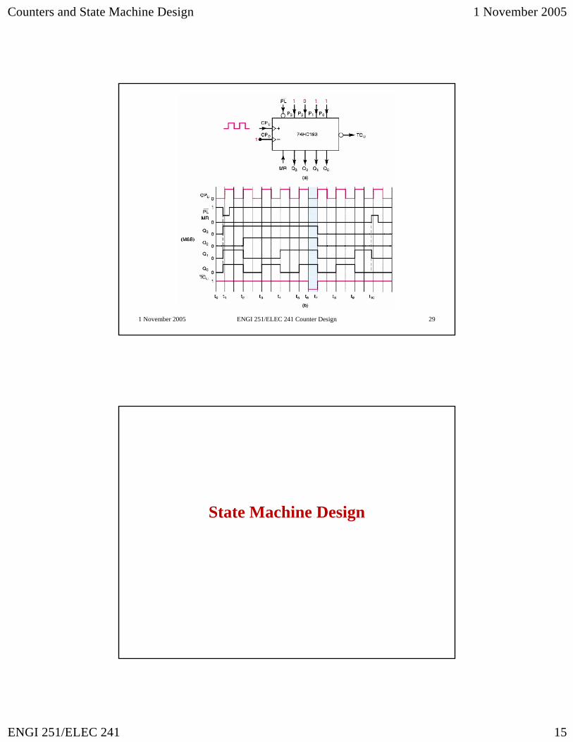
State Machine Design
Counters and State Machine Design 1 November 2005
ENGI 251/ELEC 241 16
1 November 2005 ENGI 251/ELEC 241 Counter Design 31
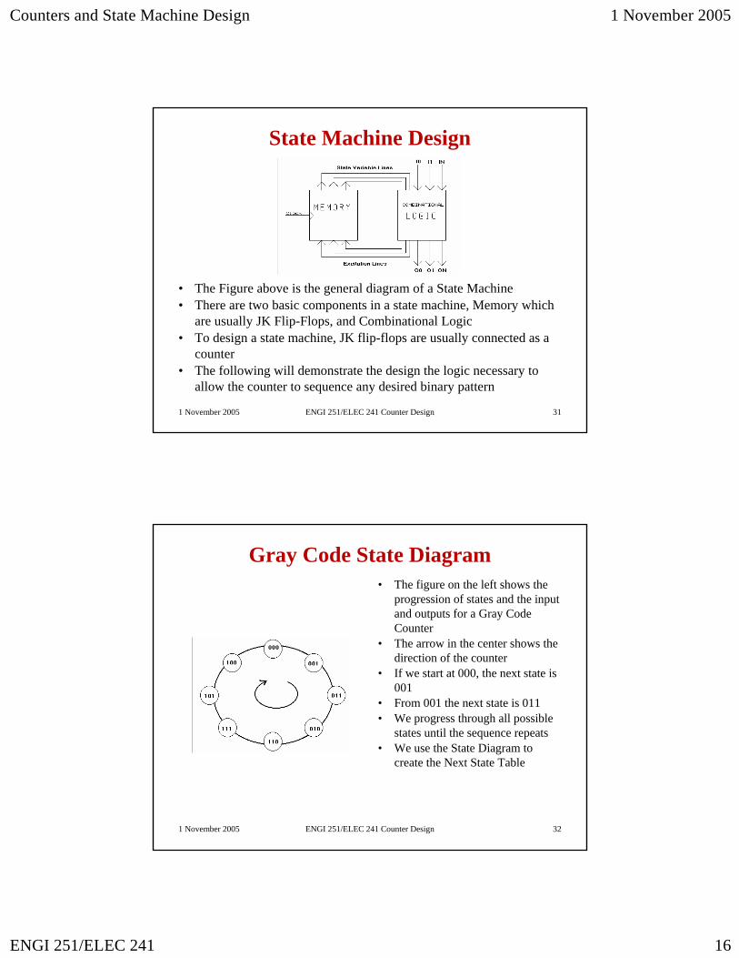
State Machine Design
• The Figure above is the general diagram of a State Machine• There are two basic components in a state machine, Memory which
are usually JK Flip-Flops, and Combinational Logic• To design a state machine, JK flip-flops are usually connected as a
counter• The following will demonstrate the design the logic necessary to
allow the counter to sequence any desired binary pattern
1 November 2005 ENGI 251/ELEC 241 Counter Design 32
Gray Code State Diagram• The figure on the left shows the
progression of states and the input and outputs for a Gray Code Counter
• The arrow in the center shows the direction of the counter
• If we start at 000, the next state is 001
• From 001 the next state is 011• We progress through all possible
states until the sequence repeats• We use the State Diagram to
create the Next State Table
Counters and State Machine Design 1 November 2005
ENGI 251/ELEC 241 17
1 November 2005 ENGI 251/ELEC 241 Counter Design 33
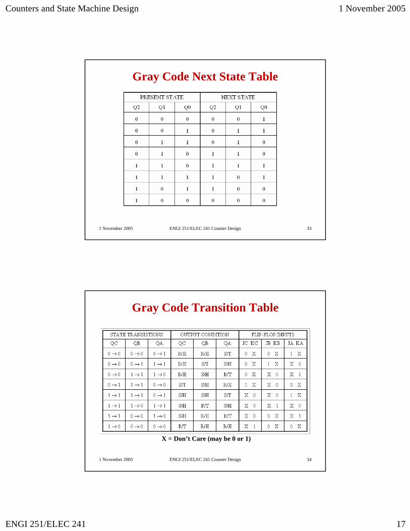
Gray Code Next State Table
1 November 2005 ENGI 251/ELEC 241 Counter Design 34
Gray Code Transition Table
X = Don’t Care (may be 0 or 1)
Counters and State Machine Design 1 November 2005
ENGI 251/ELEC 241 18
1 November 2005 ENGI 251/ELEC 241 Counter Design 35
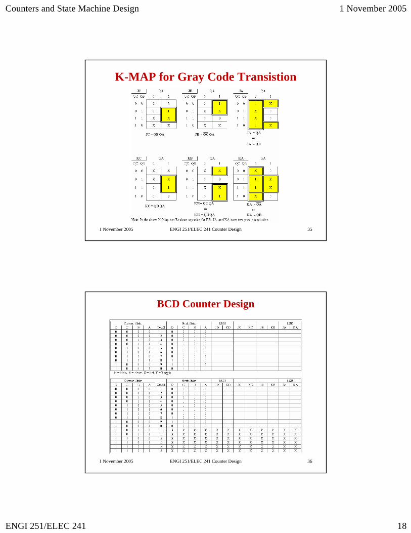
K-MAP for Gray Code Transistion
1 November 2005 ENGI 251/ELEC 241 Counter Design 36
BCD Counter Design
Counters and State Machine Design 1 November 2005
ENGI 251/ELEC 241 19
1 November 2005 ENGI 251/ELEC 241 Counter Design 37
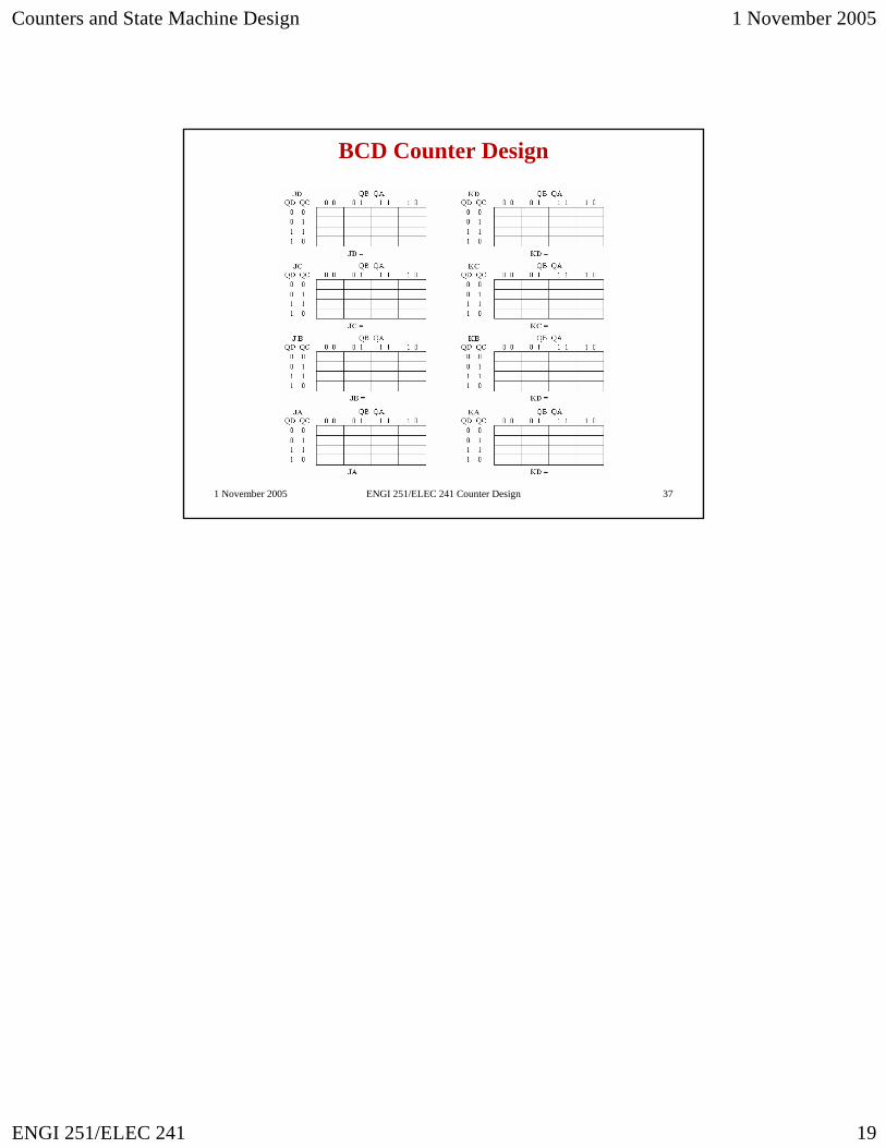
BCD Counter Design