Embed Size (px)
Citation preview
CETAC ASX-520 Family SpeedShift Utility Upgrade Kit
Manual Part Number 480174 Rev 3a
Installation Guide
COPYRIGHT
© 2010-2011 CETAC Technologies
480174 Rev 3a, February, 2011
CETAC Technologies authorizes its customers to reproduce, transmit, or store this document in its entirety, including this page, for the express purpose of installing, operating, or maintaining the product described herein.
CETAC Technologies Customer Service & Support 14306 Industrial Road Omaha, Nebraska 68144, USA Phone (800) 369-2822 (USA only) Phone (402) 733-2829 Fax (402) 733-1932 E-mail [email protected]
REVISIONS
CETAC Technologies strives to provide the scientific community with an unparalleled combination of effective technology and continuing value. Modular upgrades for existing instruments will continue to be a prime consideration as designs progress.
CETAC Technologies reserves the right to revise this document and/or improve products described herein at any time without notice or obligation. Warranty registration entitles the named owner exclusively to manual change pages/new editions as they are published.
TRADEMARK ACKNOWLEDGEMENTS
Windows is a registered trademark of Microsoft Corporation in the United States and other countries.
All other marks are the property of their respective owners.
3
Contents 1 Introduction ........................................................................................................... 5
Overview.................................................................................................................................... 5 Improved Productivity .................................................................................................... 5 Improved Economy ........................................................................................................... 5 Improved Carryover Control ........................................................................................ 5 Improved Cross-Contamination Control ................................................................. 5 Getting Started ................................................................................................................... 5
System Requirements .......................................................................................................... 6 Supported Autosampler Personalities ..................................................................... 6 Supported Firmware Versions ..................................................................................... 6
2 Upgrading the Autosampler Firmware ......................................................... 9
Upgrading Firmware to an Existing Processor Module ........................................ 9 Where to Get the Firmware .......................................................................................... 9 Preparing the Autosampler for Firmware Upgrade ........................................ 10 Establishing Communications ................................................................................... 18 Loading the Firmware .................................................................................................. 19 Configuring the Autosampler for Programming ............................................... 21 Upgrading the Firmware ............................................................................................. 21 Returning the Autosampler to its Normal Configuration ............................. 22 Verifying the Firmware Upgrade ............................................................................. 23
Upgrading Firmware by Installing a New Processor Module .......................... 23 Accessing the Interior of the Autosampler ........................................................... 23 Processor Module Installation (ASX-520) ............................................................ 33 Processor Module Installation (ASX-260) ............................................................ 34
Configuring the Autosampler Personality ................................................................ 36
3 Setting the Pump Speed Jumper ................................................................... 37
Setting the Pump Speed Jumper (ASX-520/ASX-520HS/EXR-8)...................... 37 Setting the Pump Speed Jumper (ASX-260) ............................................................. 38 Closing Up the Autosampler ........................................................................................... 39
4 Installing the Utility .......................................................................................... 41
5 Using the Utility .................................................................................................. 47
Running the utility .............................................................................................................. 47 Viewing the Current Settings.......................................................................................... 48 Changing a Setting ............................................................................................................... 49 Explanation of the Settings .............................................................................................. 49
Pump Timeout .................................................................................................................. 49 Pump Speed Level ............................................................................................................ 49 X/Y Axis Travel Speed .................................................................................................... 49 Z Axis Travel Speed ......................................................................................................... 49
ASX-520 SpeedShift Utility Upgrade Installation Guide
4
Explanation of the Controls ............................................................................................ 50 Initialize Communications .......................................................................................... 50 Set 50 Factory Reset ..................................................................................................................... 50 Test XYZ Speed .................................................................................................................. 50 Toggle Pump ...................................................................................................................... 50
Determining the Best Travel Speed for Your Application ................................. 50
6 Operating a CETAC Autosampler Using a Terminal Program ............. 51
Using C-Term™ ..................................................................................................................... 51 Starting C-Term ............................................................................................................... 51 Overview of the C-Term Window.............................................................................. 52 Configuring C-Term ........................................................................................................ 53 Setting Preferences ......................................................................................................... 54
Using HyperTerminal ........................................................................................................ 54 Autosampler Commands .................................................................................................. 58
5
1 Introduction
Overview The ASX-520 SpeedShift utility lets you control autosampler settings such as rinse pump timeout, rinse pump speed and axis speed.
Improved Productivity
The utility can shorten run times by increasing the speed of movement along the X-, Y-, and Z-axes.
Improved Economy
The utility can reduce consumption of the rinse solution by slowing the rinse pump speed. The rinse pump timeout eliminates rinse solution waste at the end of a sample run—especially for instruments which return the probe to the rinse station without turning off the pump.
Improved Carryover Control
The utility can address carryover concerns by increasing the rinse pump speed to improve probe cleaning effectiveness at the rinse station.
Improved Cross-Contamination Control
The utility can reduce the speed of axis movement to reduce the potential for droplet shedding, which can cause sample-to-sample carryover.
Getting Started
To use the utility, you will need to
1 Upgrade the autosampler firmware.
Information on the required firmware version is on page 6.
You can upgrade firmware by downloading it from a PC (see page 9), or by installing a new processor module which has the firmware pre-loaded (see page 23).
ASX-520 SpeedShift Utility Upgrade Installation Guide
6
2 Set the autosampler pump speed jumper to its fastest setting (see page 37).
3 Install the utility on the PC which controls the autosampler (see page 41).
4 Run the utility and change the settings (see page 47).
System Requirements Every autosampler has a personality and a firmware version.
To determine the personality and firmware version of your autosampler, use the VER command as described in the chapter "Operating a CETAC Autosampler Using a Terminal Program" beginning on page 51.
Supported Autosampler Personalities
The utility is compatible with CETAC ASX-520, EXR-8, and ASX-260 autosamplers with the following personalities:
CETAC Standard 520 (includes many OEM models including Thermo, Spectro and Varian/Agilent*)
CETAC Standard 520 High-Speed (includes many OEM models including Thermo and Spectro)
CETAC Standard 260 (includes many OEM models including Thermo, PerkinElmer, and Spectro)
CETAC EXR-8 (Standard and High-Speed) Perkin Elmer 520 (Standard and High-Speed) Perkin Elmer EXR-8 (Standard and High-Speed) Perkin Elmer 260 Speedy HP/Agilent 520 Micromass 520 Thermo AA 520 Finnegan Mat 520 Foss 260 Lachat 520 Lachat ASX-260
* Agilent acquired Varian in 2010. The CETAC Standard 520 personality applies to Varian version ASX-520 autosamplers, and to their Agilent equivalents.
If you have any questions regarding how to identify your current autosampler personality setting, please contact CETAC Technologies at www.cetac.com.
Supported Firmware Versions
Autosamplers manufactured after March, 2011 do not need to be upgraded to use this utility.
The utility is compatible with the following firmware versions:
Firmware version 1.14 – This version is the minimum requirement, and will allow the user to operate the pump timeout feature only. No axis or pump speed settings are available.
Firmware version 1.16 – Supports all features of the ASX-520 SpeedShift utility.
ASX-520 SpeedShift Utility Upgrade Installation Guide
Chapter 1: Introduction
7
See the next chapter for information on obtaining and upgrading the firmware. You can upgrade the firmware by setting some switches and using a firmware update utility, or by replacing the processor module in the autosampler. Contact CETAC to determine which method is most appropriate for your autosampler.
If you have any questions, concerns, or need help upgrading your firmware to be able to take full advantage of the features offered by this utility, please contact CETAC Technologies at www.cetac.com.

ASX-520 SpeedShift Utility Upgrade Installation Guide
8
This page is intentionally blank.
9
2 Upgrading the Autosampler
Firmware
If your autosampler does not have one of the supported firmware versions, but it does have a processor module which allows firmware to be updated, follow the instructions in this chapter to update the firmware. If the processor module does not allow firmware updates, see "Upgrading Firmware by Installing a New Processor Module" on page 23. Contact CETAC to determine which method is most appropriate for your autosampler.
This chapter summarizes the instructions from the Guide to Upgrading the Firmware in a Cetac ASX-520/520HS Autosampler, supplied on the software CD.
To update the firmware, you will need to disassemble the autosampler so that you can set some DIP switches.
ELECTRICAL AND MECHANICAL HAZARDS Make sure the unit is off and unplugged before beginning this procedure.
Upgrading Firmware to an Existing Processor Module
Where to Get the Firmware
The software needed to upgrade the firmware on the autosampler and the firmware upgrade file can be downloaded from the CETAC web site. To download the software and the firmware, go to http://www.cetac.com/downloads/download.html and select Autosampler Firmware Update. You will be presented with a form that asks for basic contact information. Upon completion, you will be e-mailed a web site address, a login ID and a password that will allow you to download any new
WARNING
ASX-520 SpeedShift Utility Upgrade Installation Guide
10
firmware upgrade that may be available for your autosampler along with the necessary software to perform the upgrade.
Preparing the Autosampler for Firmware Upgrade
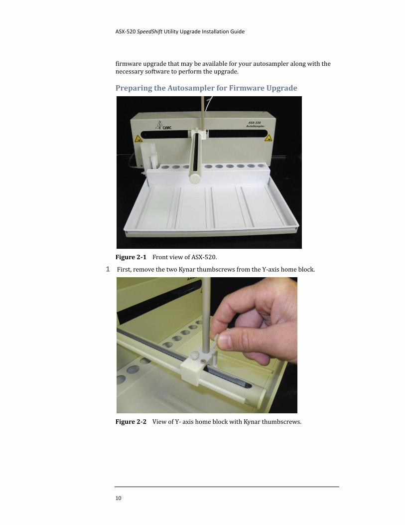
Figure 2-1 Front view of ASX-520.
1 First, remove the two Kynar thumbscrews from the Y-axis home block.
Figure 2-2 View of Y- axis home block with Kynar thumbscrews.
ASX-520 SpeedShift Utility Upgrade Installation Guide
Chapter 2: Upgrading the Autosampler Firmware
11
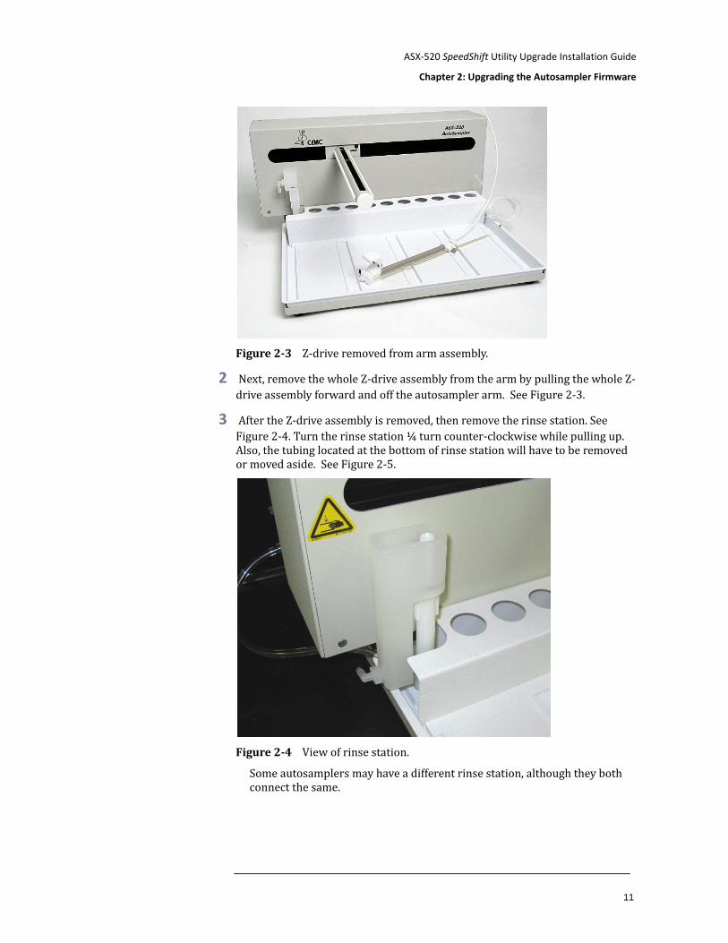
Figure 2-3 Z-drive removed from arm assembly.
2 Next, remove the whole Z-drive assembly from the arm by pulling the whole Z-drive assembly forward and off the autosampler arm. See Figure 2-3.
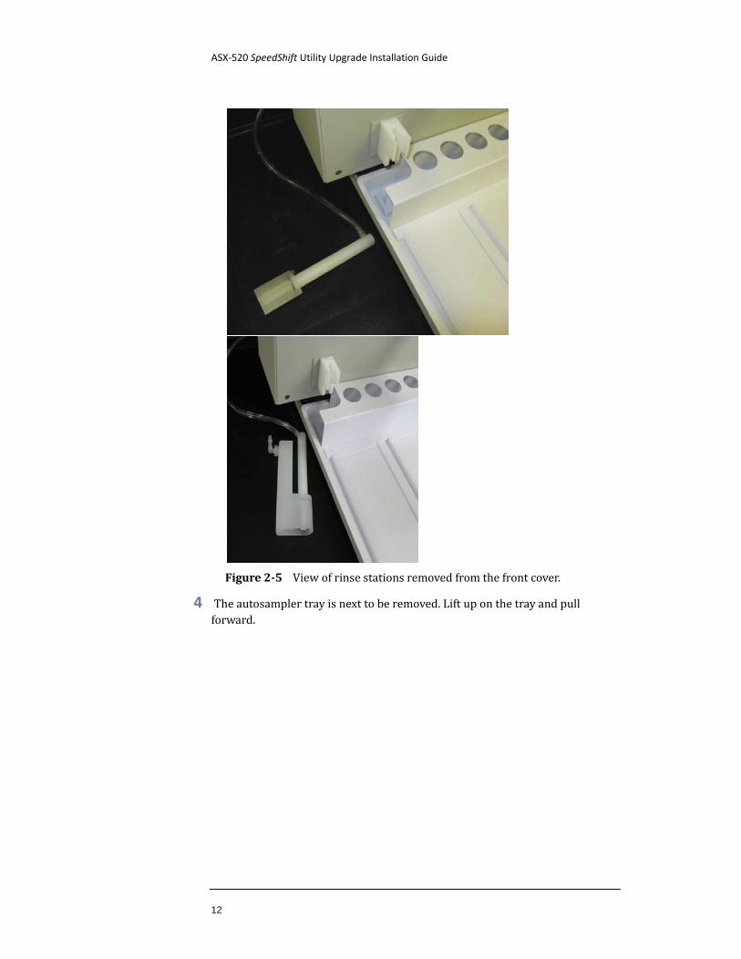
3 After the Z-drive assembly is removed, then remove the rinse station. See Figure 2-4. Turn the rinse station ¼ turn counter-clockwise while pulling up. Also, the tubing located at the bottom of rinse station will have to be removed or moved aside. See Figure 2-5.
Figure 2-4 View of rinse station.
Some autosamplers may have a different rinse station, although they both connect the same.
ASX-520 SpeedShift Utility Upgrade Installation Guide
12
Figure 2-5 View of rinse stations removed from the front cover.
4 The autosampler tray is next to be removed. Lift up on the tray and pull forward.
ASX-520 SpeedShift Utility Upgrade Installation Guide
Chapter 2: Upgrading the Autosampler Firmware
13
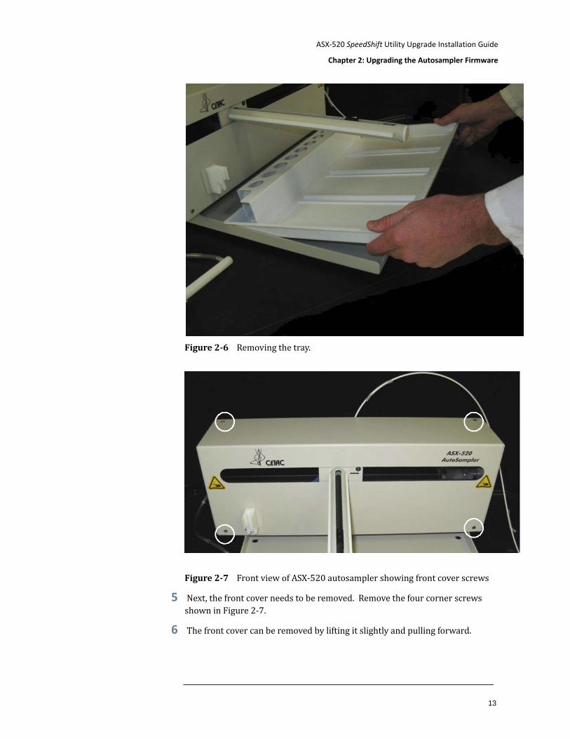
Figure 2-6 Removing the tray.
Figure 2-7 Front view of ASX-520 autosampler showing front cover screws
5 Next, the front cover needs to be removed. Remove the four corner screws shown in Figure 2-7.
6 The front cover can be removed by lifting it slightly and pulling forward.
ASX-520 SpeedShift Utility Upgrade Installation Guide
14
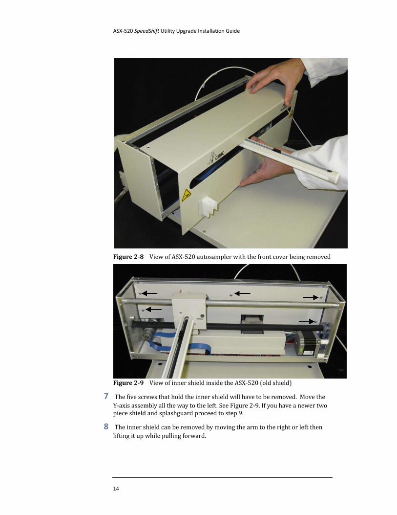
Figure 2-8 View of ASX-520 autosampler with the front cover being removed
Figure 2-9 View of inner shield inside the ASX-520 (old shield)
7 The five screws that hold the inner shield will have to be removed. Move the Y-axis assembly all the way to the left. See Figure 2-9. If you have a newer two piece shield and splashguard proceed to step 9.
8 The inner shield can be removed by moving the arm to the right or left then lifting it up while pulling forward.
ASX-520 SpeedShift Utility Upgrade Installation Guide
Chapter 2: Upgrading the Autosampler Firmware
15
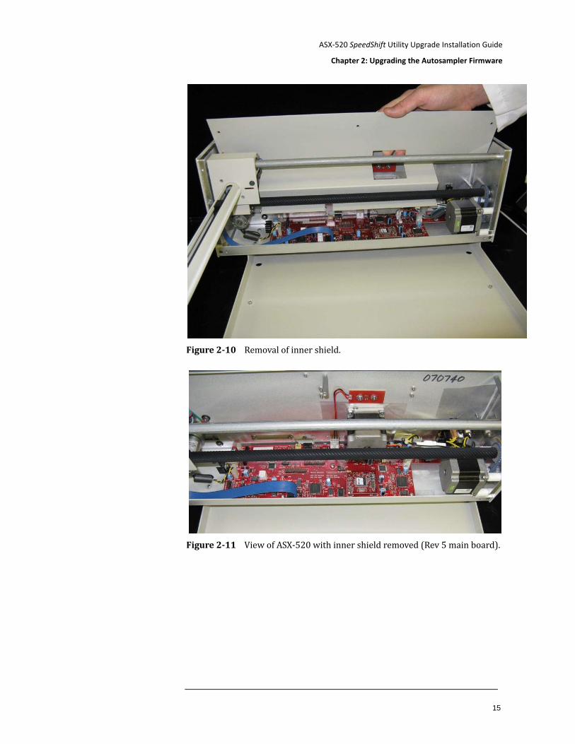
Figure 2-10 Removal of inner shield.
Figure 2-11 View of ASX-520 with inner shield removed (Rev 5 main board).
ASX-520 SpeedShift Utility Upgrade Installation Guide
16
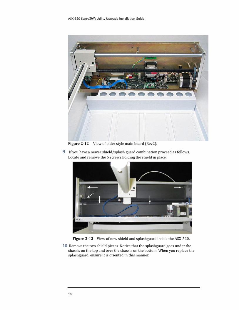
Figure 2-12 View of older style main board (Rev2).
9 If you have a newer shield/splash guard combination proceed as follows. Locate and remove the 5 screws holding the shield in place.
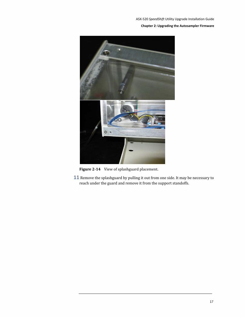
Figure 2-13 View of new shield and splashguard inside the ASX-520.
10 Remove the two shield pieces. Notice that the splashguard goes under the chassis on the top and over the chassis on the bottom. When you replace the splashguard, ensure it is oriented in this manner.
ASX-520 SpeedShift Utility Upgrade Installation Guide
Chapter 2: Upgrading the Autosampler Firmware
17
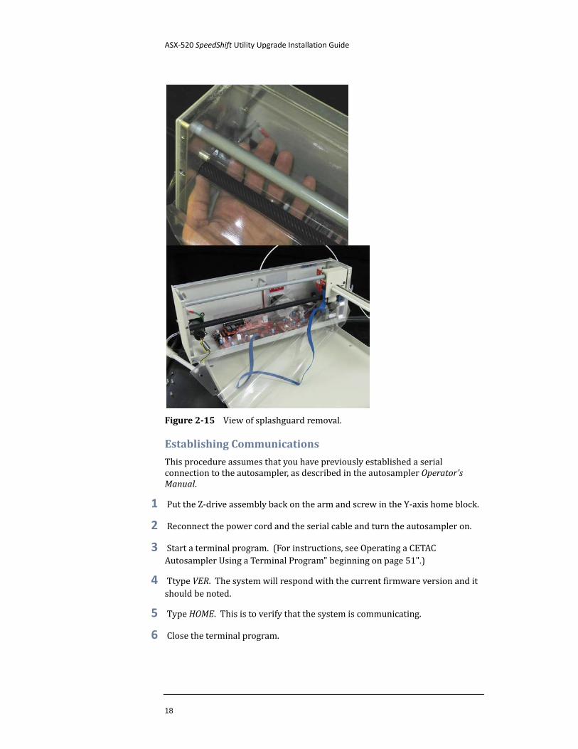
Figure 2-14 View of splashguard placement.
11 Remove the splashguard by pulling it out from one side. It may be necessary to reach under the guard and remove it from the support standoffs.
ASX-520 SpeedShift Utility Upgrade Installation Guide
18
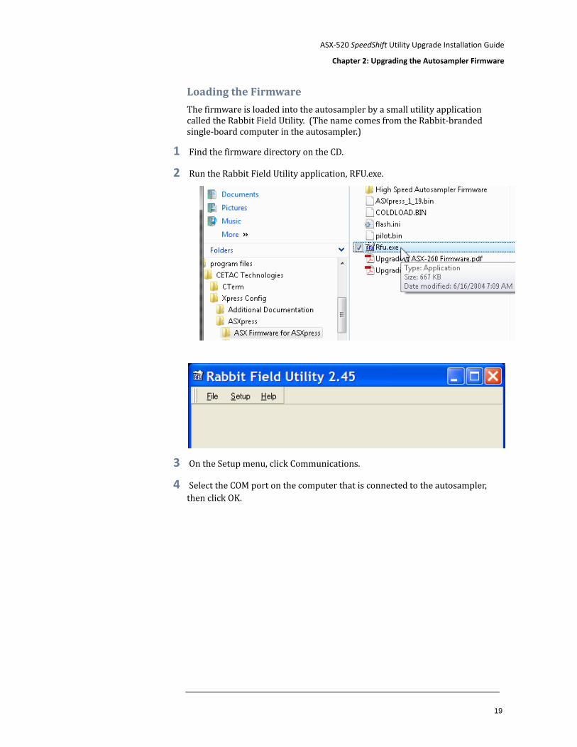
Figure 2-15 View of splashguard removal.
Establishing Communications
This procedure assumes that you have previously established a serial connection to the autosampler, as described in the autosampler Operator's Manual.
1 Put the Z-drive assembly back on the arm and screw in the Y-axis home block.
2 Reconnect the power cord and the serial cable and turn the autosampler on.
3 Start a terminal program. (For instructions, see Operating a CETAC Autosampler Using a Terminal Program" beginning on page 51".)
4 Ttype VER. The system will respond with the current firmware version and it should be noted.
5 Type HOME. This is to verify that the system is communicating.
6 Close the terminal program.
ASX-520 SpeedShift Utility Upgrade Installation Guide
Chapter 2: Upgrading the Autosampler Firmware
19
Loading the Firmware
The firmware is loaded into the autosampler by a small utility application called the Rabbit Field Utility. (The name comes from the Rabbit-branded single-board computer in the autosampler.)
1 Find the firmware directory on the CD.
2 Run the Rabbit Field Utility application, RFU.exe.
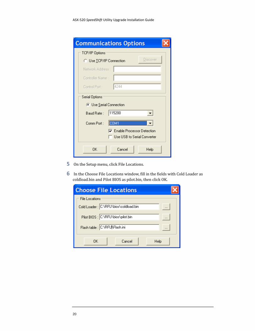
3 On the Setup menu, click Communications.
4 Select the COM port on the computer that is connected to the autosampler, then click OK.
ASX-520 SpeedShift Utility Upgrade Installation Guide
20
5 On the Setup menu, click File Locations.
6 In the Choose File Locations window, fill in the fields with Cold Loader as coldload.bin and Pilot BIOS as pilot.bin, then click OK.
ASX-520 SpeedShift Utility Upgrade Installation Guide
Chapter 2: Upgrading the Autosampler Firmware
21
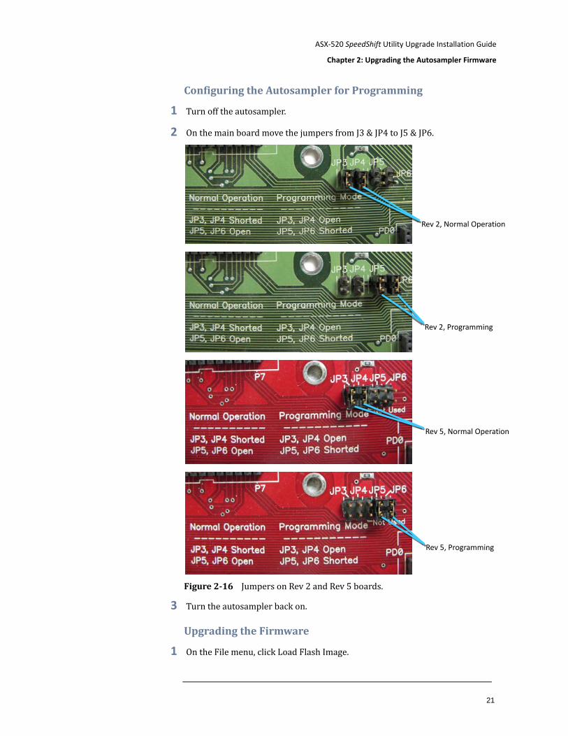
Configuring the Autosampler for Programming
1 Turn off the autosampler.
2 On the main board move the jumpers from J3 & JP4 to J5 & JP6.
Figure 2-16 Jumpers on Rev 2 and Rev 5 boards.
3 Turn the autosampler back on.
Upgrading the Firmware
1 On the File menu, click Load Flash Image.
Rev 2, Normal Operation
Rev 2, Programming
Rev 5, Normal Operation
Rev 5, Programming
ASX-520 SpeedShift Utility Upgrade Installation Guide
22
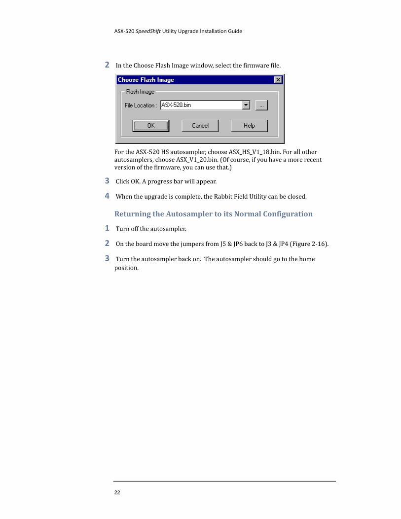
2 In the Choose Flash Image window, select the firmware file.
For the ASX-520 HS autosampler, choose ASX_HS_V1_18.bin. For all other autosamplers, choose ASX_V1_20.bin. (Of course, if you have a more recent version of the firmware, you can use that.)
3 Click OK. A progress bar will appear.
4 When the upgrade is complete, the Rabbit Field Utility can be closed.
Returning the Autosampler to its Normal Configuration
1 Turn off the autosampler.
2 On the board move the jumpers from J5 & JP6 back to J3 & JP4 (Figure 2-16).
3 Turn the autosampler back on. The autosampler should go to the home position.
ASX-520 SpeedShift Utility Upgrade Installation Guide
Chapter 2: Upgrading the Autosampler Firmware
23
Verifying the Firmware Upgrade
1 Start a terminal program as described beginning on page 51.
2 Enter the VER or VERSS command. The system should respond with the new firmware version.
3 Turn off the autosampler.
4 Remove the Z-drive assembly from the y-arm.
5 Install the splash guard, if equipped, taking note of the top and bottom edge placement as noted earlier.
6 Install the inner shield.
7 Replace cover and rinse station.
8 Replace z-drive assembly.
9 Reconnect the power cord and turn on the power switch.
Upgrading Firmware by Installing a New Processor Module In some cases, it may be necessary to install a new processor module, sometimes called a "Rabbit module."
Most of the steps apply to the ASX-260, EXR-8, ASX-520 and ASX-520HS autosamplers. In some places, the steps are different for the ASX-260.
NOTE
Your equipment may differ in appearance from what is shown in the photos. The photos show components which are intended to represent typical CETAC instruments from a range of eras.
Accessing the Interior of the Autosampler
1 Place the autosampler on a flat surface and ensure that the unit is powered off.
ASX-520 SpeedShift Utility Upgrade Installation Guide
24
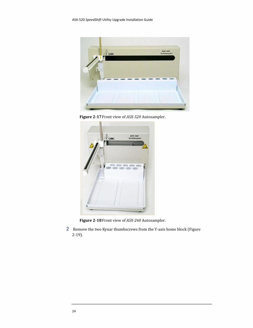
Figure 2-17 Front view of ASX-520 Autosampler.
Figure 2-18 Front view of ASX-260 Autosampler.
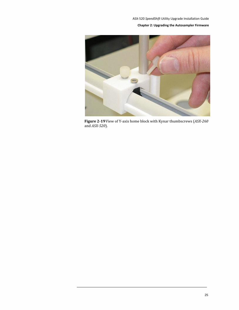
2 Remove the two Kynar thumbscrews from the Y-axis home block (Figure 2-19).
ASX-520 SpeedShift Utility Upgrade Installation Guide
Chapter 2: Upgrading the Autosampler Firmware
25
Figure 2-19 View of Y-axis home block with Kynar thumbscrews (ASX-260 and ASX-520).
ASX-520 SpeedShift Utility Upgrade Installation Guide
26
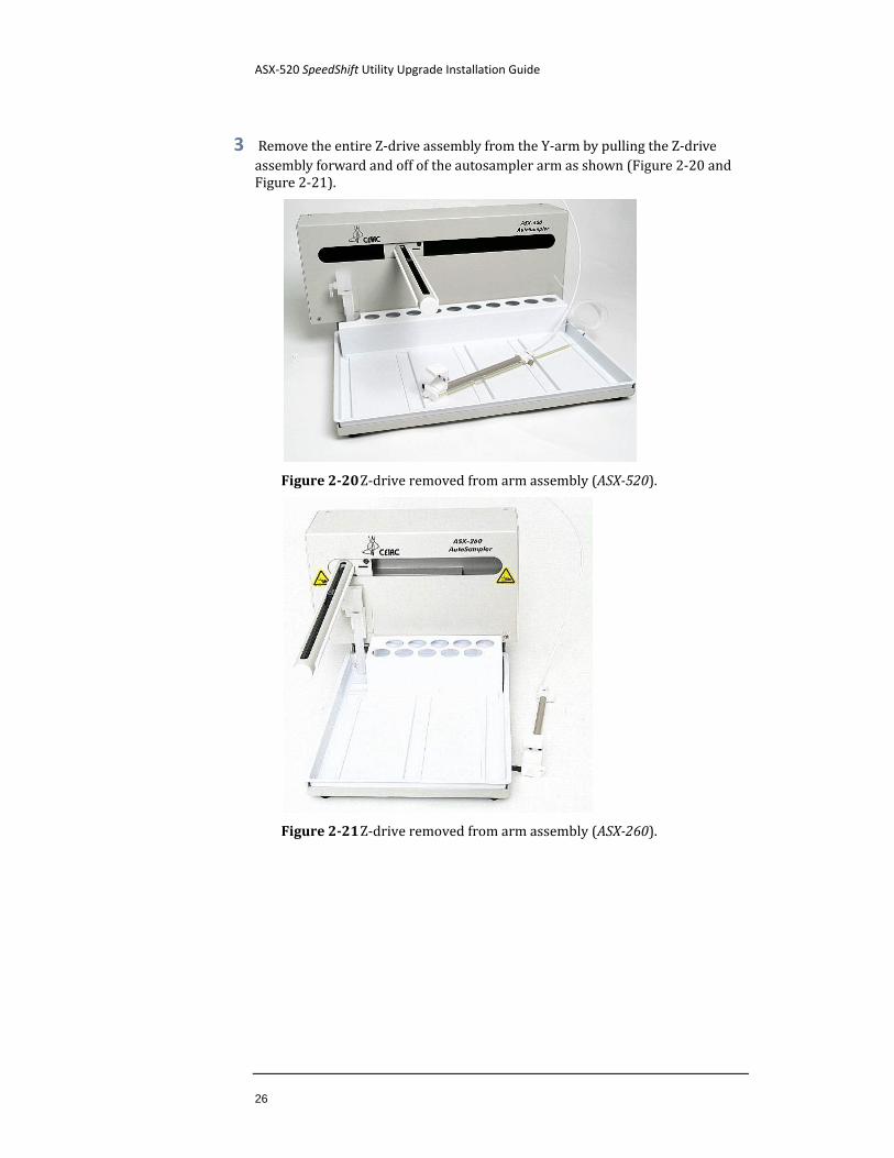
3 Remove the entire Z-drive assembly from the Y-arm by pulling the Z-drive assembly forward and off of the autosampler arm as shown (Figure 2-20 and Figure 2-21).
Figure 2-20 Z-drive removed from arm assembly (ASX-520).
Figure 2-21 Z-drive removed from arm assembly (ASX-260).
ASX-520 SpeedShift Utility Upgrade Installation Guide
Chapter 2: Upgrading the Autosampler Firmware
27
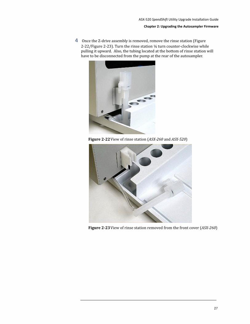
4 Once the Z-drive assembly is removed, remove the rinse station (Figure 2-22/Figure 2-23). Turn the rinse station ¼ turn counter-clockwise while pulling it upward. Also, the tubing located at the bottom of rinse station will have to be disconnected from the pump at the rear of the autosampler.
Figure 2-22 View of rinse station (ASX-260 and ASX-520)
Figure 2-23 View of rinse station removed from the front cover (ASX-260)
ASX-520 SpeedShift Utility Upgrade Installation Guide
28
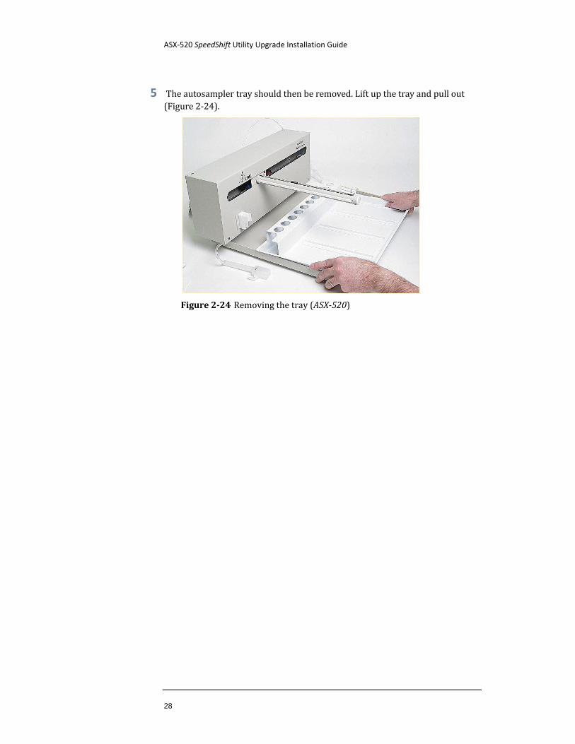
5 The autosampler tray should then be removed. Lift up the tray and pull out (Figure 2-24).
Figure 2-24 Removing the tray (ASX-520)
ASX-520 SpeedShift Utility Upgrade Installation Guide
Chapter 2: Upgrading the Autosampler Firmware
29
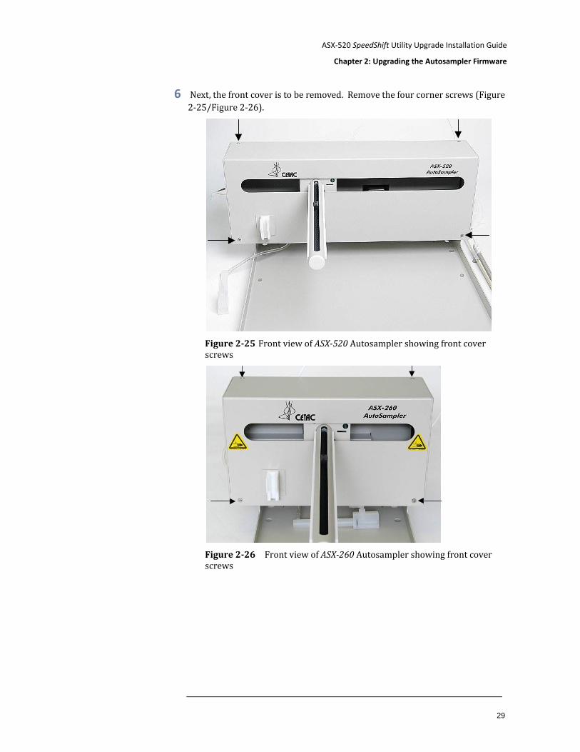
6 Next, the front cover is to be removed. Remove the four corner screws (Figure 2-25/Figure 2-26).
Figure 2-25 Front view of ASX-520 Autosampler showing front cover screws
Figure 2-26 Front view of ASX-260 Autosampler showing front cover screws
ASX-520 SpeedShift Utility Upgrade Installation Guide
30
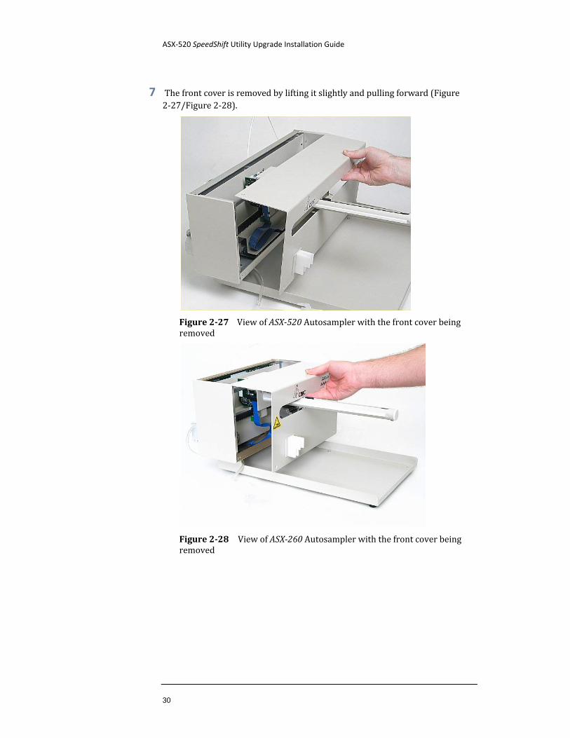
7 The front cover is removed by lifting it slightly and pulling forward (Figure 2-27/Figure 2-28).
Figure 2-27 View of ASX-520 Autosampler with the front cover being removed
Figure 2-28 View of ASX-260 Autosampler with the front cover being removed
ASX-520 SpeedShift Utility Upgrade Installation Guide
Chapter 2: Upgrading the Autosampler Firmware
31
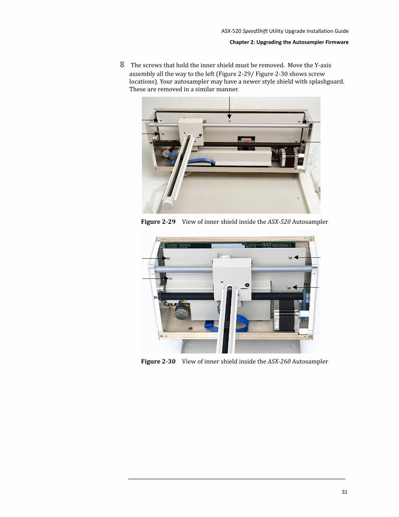
8 The screws that hold the inner shield must be removed. Move the Y-axis assembly all the way to the left (Figure 2-29/ Figure 2-30 shows screw locations). Your autosampler may have a newer style shield with splashguard. These are removed in a similar manner.
Figure 2-29 View of inner shield inside the ASX-520 Autosampler
Figure 2-30 View of inner shield inside the ASX-260 Autosampler
ASX-520 SpeedShift Utility Upgrade Installation Guide
32
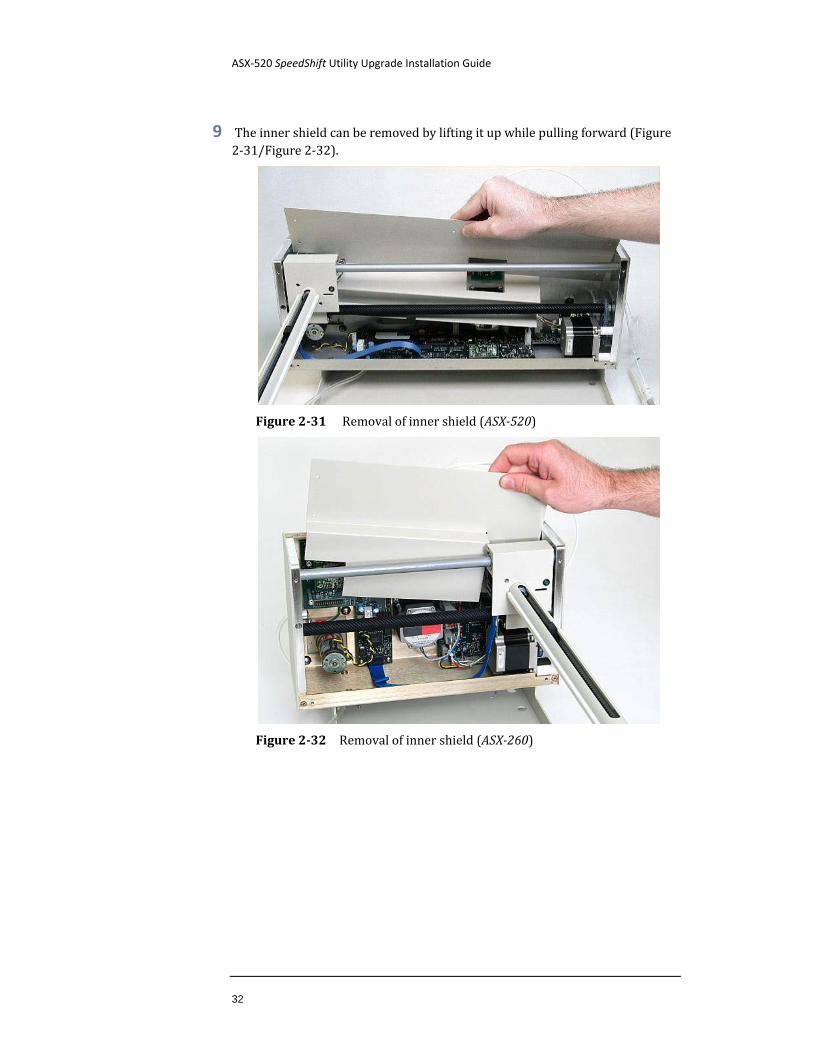
9 The inner shield can be removed by lifting it up while pulling forward (Figure 2-31/Figure 2-32).
Figure 2-31 Removal of inner shield (ASX-520)
Figure 2-32 Removal of inner shield (ASX-260)
ASX-520 SpeedShift Utility Upgrade Installation Guide
Chapter 2: Upgrading the Autosampler Firmware
33
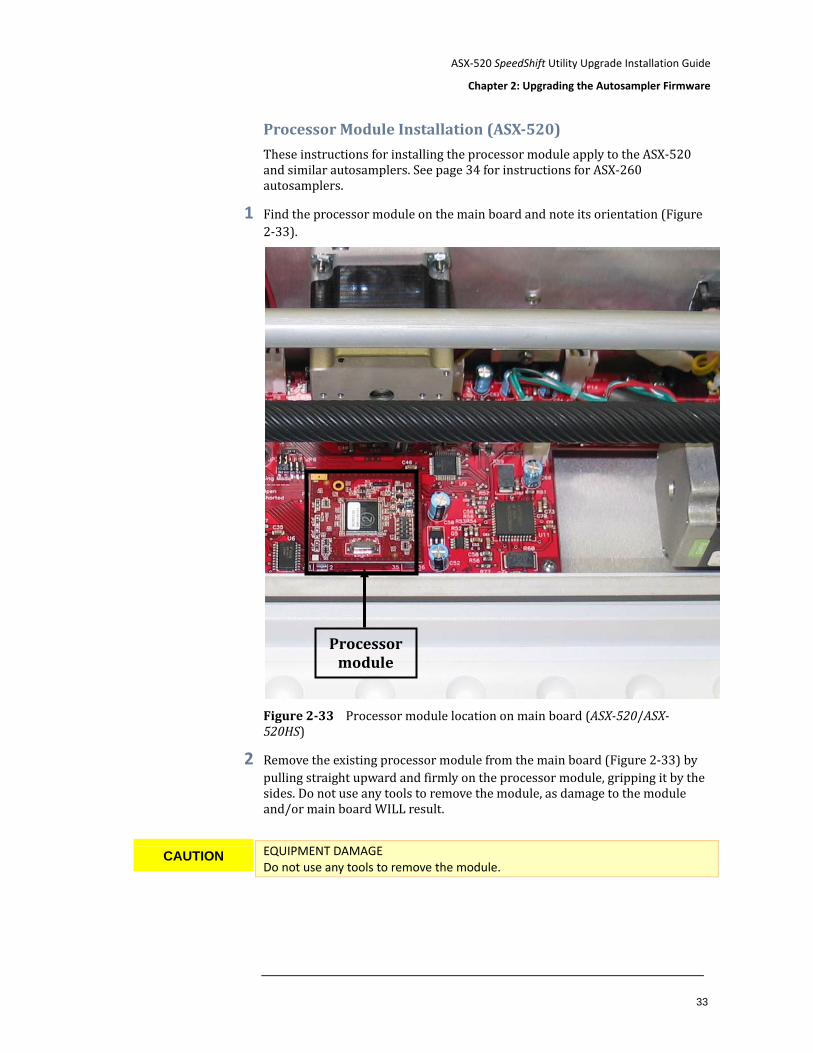
Processor Module Installation (ASX-520)
These instructions for installing the processor module apply to the ASX-520 and similar autosamplers. See page 34 for instructions for ASX-260 autosamplers.
1 Find the processor module on the main board and note its orientation (Figure 2-33).
Figure 2-33 Processor module location on main board (ASX-520/ASX-520HS)
2 Remove the existing processor module from the main board (Figure 2-33) by pulling straight upward and firmly on the processor module, gripping it by the sides. Do not use any tools to remove the module, as damage to the module and/or main board WILL result.
EQUIPMENT DAMAGE Do not use any tools to remove the module.
CAUTION
Processor module
ASX-520 SpeedShift Utility Upgrade Installation Guide
34
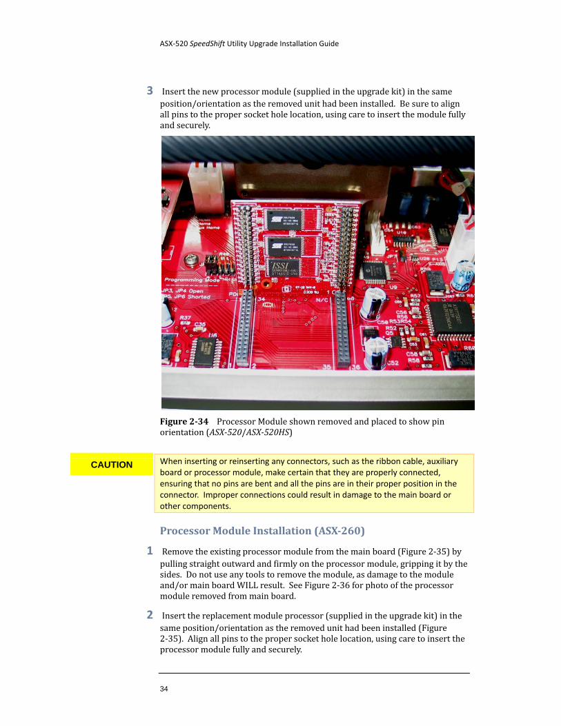
3 Insert the new processor module (supplied in the upgrade kit) in the same position/orientation as the removed unit had been installed. Be sure to align all pins to the proper socket hole location, using care to insert the module fully and securely.
Figure 2-34 Processor Module shown removed and placed to show pin orientation (ASX-520/ASX-520HS)
When inserting or reinserting any connectors, such as the ribbon cable, auxiliary board or processor module, make certain that they are properly connected, ensuring that no pins are bent and all the pins are in their proper position in the connector. Improper connections could result in damage to the main board or other components.
Processor Module Installation (ASX-260)
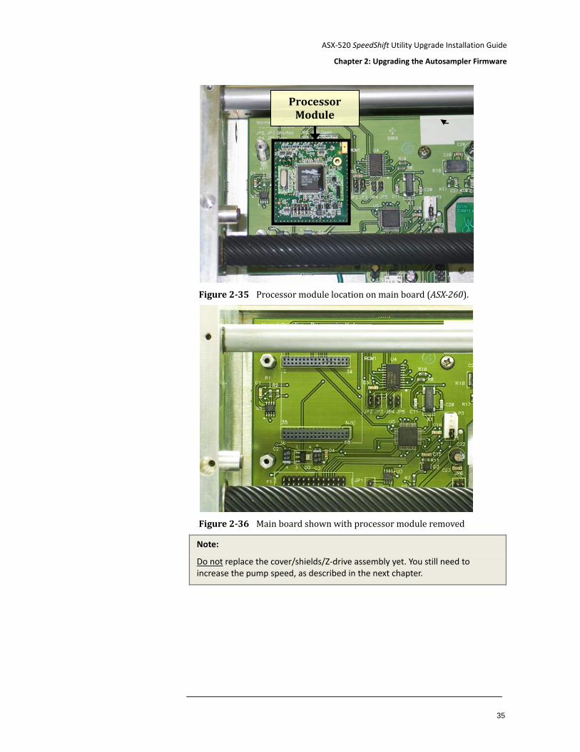
1 Remove the existing processor module from the main board (Figure 2-35) by pulling straight outward and firmly on the processor module, gripping it by the sides. Do not use any tools to remove the module, as damage to the module and/or main board WILL result. See Figure 2-36 for photo of the processor module removed from main board.
2 Insert the replacement module processor (supplied in the upgrade kit) in the same position/orientation as the removed unit had been installed (Figure 2-35). Align all pins to the proper socket hole location, using care to insert the processor module fully and securely.
CAUTION
ASX-520 SpeedShift Utility Upgrade Installation Guide
Chapter 2: Upgrading the Autosampler Firmware
35
Figure 2-35 Processor module location on main board (ASX-260).
Figure 2-36 Main board shown with processor module removed
Note:
Do not
replace the cover/shields/Z-drive assembly yet. You still need to increase the pump speed, as described in the next chapter.
Processor Module
ASX-520 SpeedShift Utility Upgrade Installation Guide
36
Configuring the Autosampler Personality Several different configurations, or personalities, are built into the autosampler firmware. When you replace the processor module, this personality may need to be set.
1 Connect a terminal emulation to the autosampler.
The autosampler can be controlled using a serial communications protocol. See “Operating a CETAC Autosampler Using a Terminal Program” on page 51. You can use any terminal emulation program, including:
C-Term. (recommended) This program provided is on the software CD, and runs on Windows 2000 and later.
HyperTerminal. This program was supplied with versions of the Windows operating system through Windows XP.
2 Enter the command
VER
3 The information returned will include the personality description.
4 If the personality shown is not appropriate for your autosampler, contact CETAC to obtain the correct "SETTYPE" personality number.
5 Enter the command
SETTYPE=nnn
where nnn is the personality number.
6 Cycle power on the autosampler.
7 Verify the personality with the VER command.
To reset the firmware to the ASX-520 Standard configuration, two "~" characters in succession should be sent. The system will respond with an "OK:".
37
3 Setting the Pump Speed Jumper
The ASX-520 SpeedShift utility can control the peristaltic pump speed. But the pump speed can also be controlled by moving a jumper on the autosampler's circuit board. The utility assumes that the jumper is set to the highest speed. Therefore, it may be necessary to move the jumper.
What happens if the jumper is not set to the highest speed? The speed of the pump will be less than the speed set by the ASX-520 SpeedShift utility. At lower speed settings, the pump might not run at all because the voltage being applied to the pump is insufficient for it to overcome friction.
Setting the Pump Speed Jumper (ASX-520/ASX-520HS/EXR-8)
1 Locate the block of pump speed pins on the left side of the ASX-520/ASX-520HS main circuit board
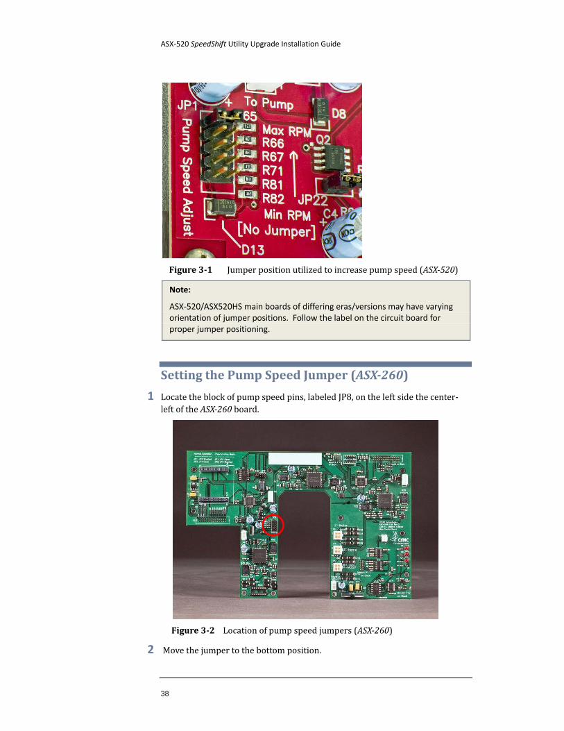
2 Move the jumper from its existing position to the position marked “Max RPM” (Figure 3-1).
ASX-520 SpeedShift Utility Upgrade Installation Guide
38
Figure 3-1 Jumper position utilized to increase pump speed (ASX-520)
Note:
ASX-520/ASX520HS main boards of differing eras/versions may have varying orientation of jumper positions. Follow the label on the circuit board for proper jumper positioning.
Setting the Pump Speed Jumper (ASX-260)
1 Locate the block of pump speed pins, labeled JP8, on the left side the center-left of the ASX-260 board.
Figure 3-2 Location of pump speed jumpers (ASX-260)
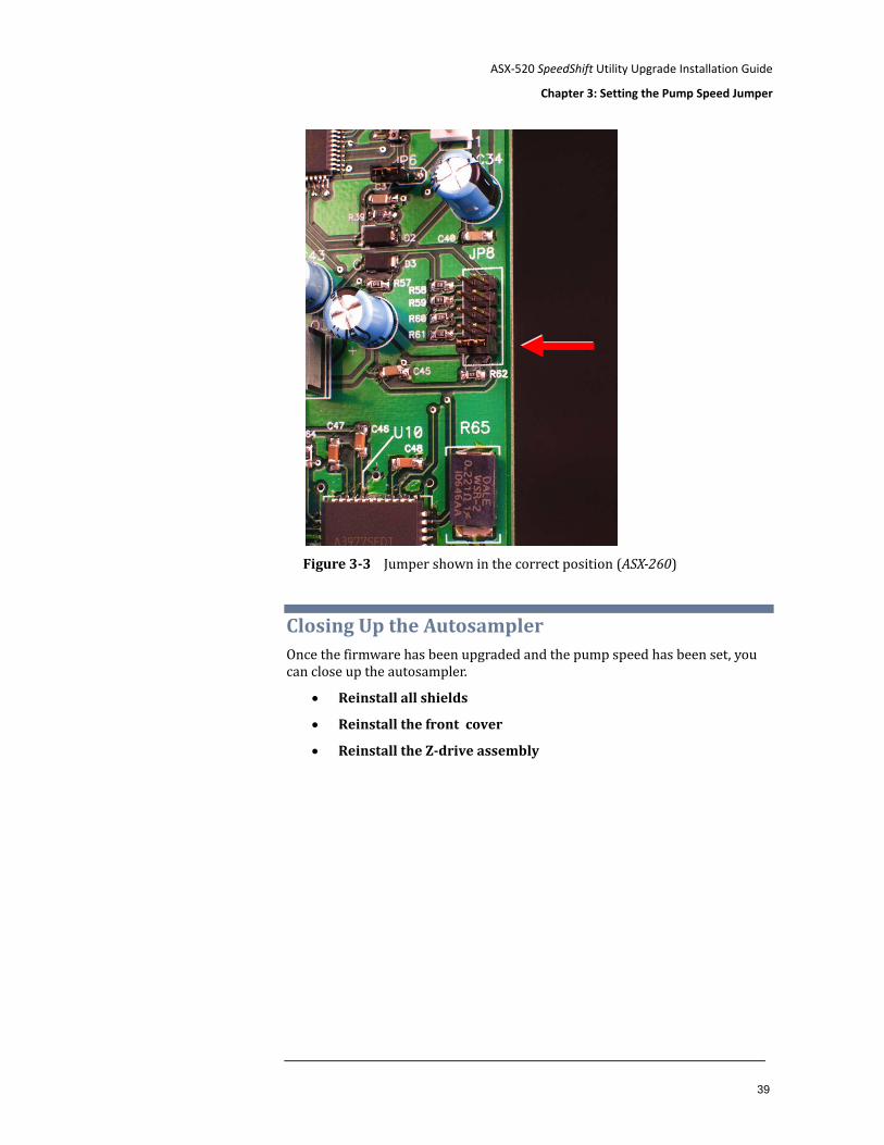
2 Move the jumper to the bottom position.
ASX-520 SpeedShift Utility Upgrade Installation Guide
Chapter 3: Setting the Pump Speed Jumper
39
Figure 3-3 Jumper shown in the correct position (ASX-260)
Closing Up the Autosampler Once the firmware has been upgraded and the pump speed has been set, you can close up the autosampler.
• Reinstall all shields
• Reinstall the front cover
• Reinstall the Z-drive assembly

ASX-520 SpeedShift Utility Upgrade Installation Guide
40
This page is intentionally blank.
41
4 Installing the Utility
These instructions show installation on a Windows XP system. Other operating systems may display additional prompts.
1 Insert the supplied CD.
The installation software will autorun when the disc is loaded into the CD-ROM drive of the host computer.
If the CD does not autorun, or if the software was downloaded, use Windows Explorer to open the location containing the software, then select “Setup Launcher” (Figure 4-1) to begin the software installation.
Figure 4-1 Setup Launcher
Follow the prompts of the Installation Wizard to complete the installation of the utility.
ASX-520 SpeedShift Utility Upgrade Installation Guide
42
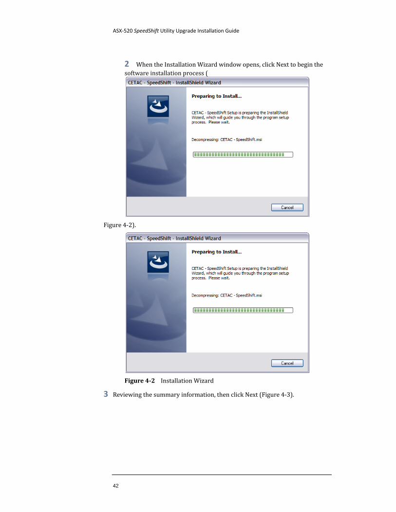
2 When the Installation Wizard window opens, click Next to begin the software installation process (
Figure 4-2).
Figure 4-2 Installation Wizard
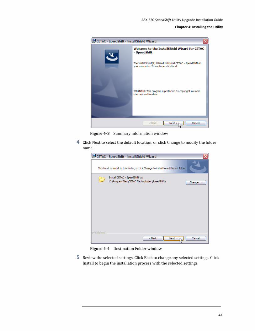
3 Reviewing the summary information, then click Next (Figure 4-3).
ASX-520 SpeedShift Utility Upgrade Installation Guide
Chapter 4: Installing the Utility
43
Figure 4-3 Summary information window
4 Click Next to select the default location, or click Change to modify the folder name.
Figure 4-4 Destination Folder window
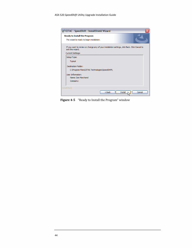
5 Review the selected settings. Click Back to change any selected settings. Click Install to begin the installation process with the selected settings.
ASX-520 SpeedShift Utility Upgrade Installation Guide
44
Figure 4-5 “Ready to Install the Program” window
ASX-520 SpeedShift Utility Upgrade Installation Guide
Chapter 4: Installing the Utility
45
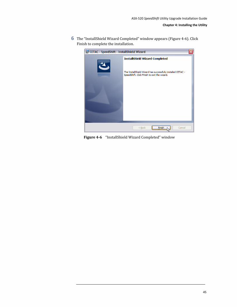
6 The “InstallShield Wizard Completed” window appears (Figure 4-6). Click Finish to complete the installation.
Figure 4-6 “InstallShield Wizard Completed” window

ASX-520 SpeedShift Utility Upgrade Installation Guide
46
This page is intentionally blank.
47
5 Using the Utility
Running the utility
1 Make sure the autosampler is connected to the host computer.
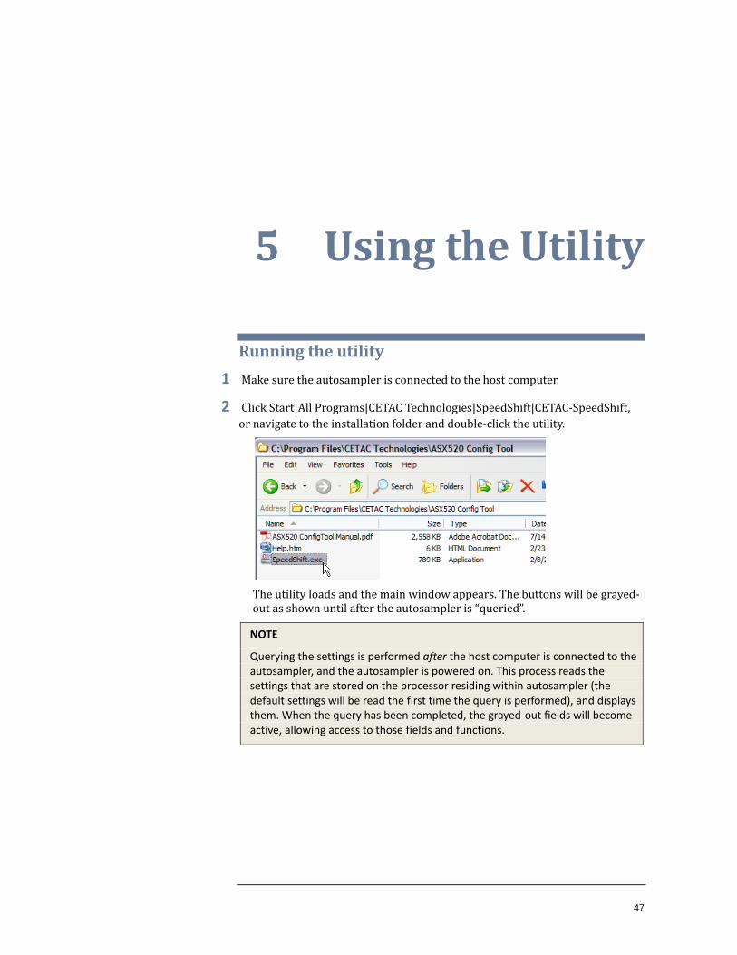
2 Click Start|All Programs|CETAC Technologies|SpeedShift|CETAC-SpeedShift, or navigate to the installation folder and double-click the utility.
The utility loads and the main window appears. The buttons will be grayed-out as shown until after the autosampler is “queried”.
NOTE
Querying the settings is performed after the host computer is connected to the autosampler, and the autosampler is powered on. This process reads the settings that are stored on the processor residing within autosampler (the default settings will be read the first time the query is performed), and displays them. When the query has been completed, the grayed-out fields will become active, allowing access to those fields and functions.
ASX-520 SpeedShift Utility Upgrade Installation Guide
48
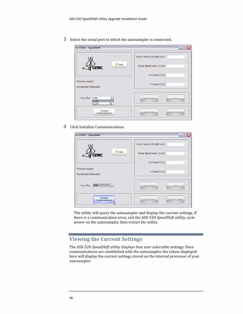
3 Select the serial port to which the autosampler is connected.
4 Click Initialize Communications.
The utility will query the autosampler and display the current settings. If there is a communication error, exit the ASX-520 SpeedShift utility, cycle power on the autosampler, then restart the utility.
Viewing the Current Settings The ASX-520 SpeedShift utility displays four user selectable settings. Once communications are established with the autosampler, the values displayed here will display the current settings stored on the internal processor of your autosampler.
ASX-520 SpeedShift Utility Upgrade Installation Guide
Chapter 5: Using the Utility
49
Changing a Setting The process for modifying any setting is as follows:
1 Select the appropriate COM port from the drop down menu.
2 Click Initialize Communications.
3 Change the chosen setting(s) to the desired values.
4 Click Set.
You may change one or more setting at one time.
Explanation of the Settings
Pump Timeout
Peristaltic pump timeout in seconds. The timeout controls how long the pump will run when the probe is in the rinse station and no other commands are sent to the autosampler. Setting the timeout to zero disables the timeout feature. Default=0.
Pump Speed Level
Peristaltic pump speed. The pump speed can be adjusted between 1 and 10, with 10 being the maximum speed. Default=4.
X/Y Axis Travel Speed
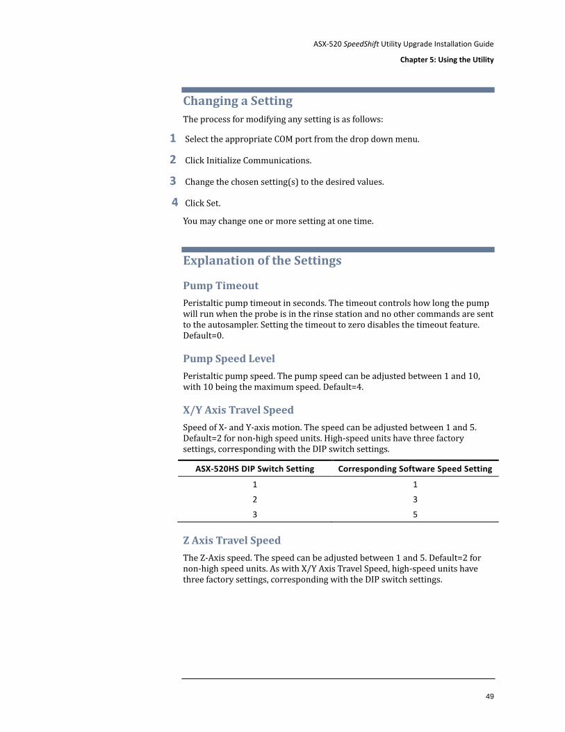
Speed of X- and Y-axis motion. The speed can be adjusted between 1 and 5. Default=2 for non-high speed units. High-speed units have three factory settings, corresponding with the DIP switch settings.
ASX-520HS DIP Switch Setting Corresponding Software Speed Setting
1 1
2 3
3 5
Z Axis Travel Speed
The Z-Axis speed. The speed can be adjusted between 1 and 5. Default=2 for non-high speed units. As with X/Y Axis Travel Speed, high-speed units have three factory settings, corresponding with the DIP switch settings.
ASX-520 SpeedShift Utility Upgrade Installation Guide
50
Explanation of the Controls
Initialize Communications
Sets up a communications channel between the utility and the autosampler. Before pressing this button, check that that the proper COM port has been selected.
Set
Sends the new settings to the autosampler. This process takes about 5-10 seconds. A small progress window will pop up to show the process.
Factory Reset
Configures the autosampler to use the original factory settings.
Test XYZ Speed
Exercises the autosampler in all three axes so you can see how speed changes affect the machine.
Toggle Pump
Turns the pump on and off. Use this to test the pump speed. The pump timeout does not apply when the pump is turned on using this button.
Determining the Best Travel Speed for Your Application For ASX-260 and ASX-520 autosamplers, it may not be possible to use the highest speed setting. At higher speeds, the sudden acceleration and deceleration may cause droplet shedding from the probe tip, causing cross contamination.
ASX-520HS autosamplers use an advanced acceleration algorithm which largely prevents these problems.
NOTE
Use caution when increasing the travel speed. Depending on the sample matrix, faster speeds have the potential for droplet shedding from the sample probe. Droplets could land in other samples or on nearby surfaces.
51
6 Operating a CETAC Autosampler Using a
Terminal Program
CETAC autosamplers can be controlled using a serial communications protocol. You can use any terminal emulation program, including:
C-Term. This program is provided on the software CD, or it can be downloaded from the CETAC Web site. It runs on Windows 2000 and later. (recommended)
HyperTerminal. This program was supplied with versions of the Windows operating system through Windows XP.
This chapter explains how to operate a CETAC autosampler using either of the two programs.
Using C-Term™ C-Term is a simple terminal program developed to validate the installation and functionality of various CETAC devices. C-Term communicates through a serial (RS-232) port on the host computer. If the device is connected to a USB port, the device driver will create a virtual serial port.
C-Term is provided on the CETAC software CD.
Starting C-Term
1 Check that the communication port connectors are properly attached between the host computer and the CETAC device.
If the communications interface between the CETAC device and the host computer is not established correctly, the device will not function.
2 On the Start Menu, click All Programs, then CETAC, then Support Tools, then C-Term.
ASX-520 SpeedShift Utility Upgrade Installation Guide
52
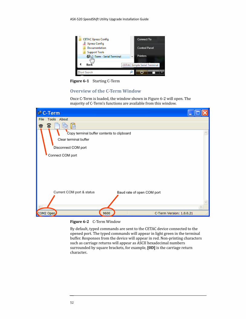
Figure 6-1 Starting C-Term
Overview of the C-Term Window
Once C-Term is loaded, the window shown in Figure 6-2 will open. The majority of C-Term’s functions are available from this window.
Figure 6-2 C-Term Window
By default, typed commands are sent to the CETAC device connected to the opened port. The typed commands will appear in light green in the terminal buffer. Responses from the device will appear in red. Non-printing characters such as carriage returns will appear as ASCII hexadecimal numbers surrounded by square brackets, for example, [0D] is the carriage return character.
ASX-520 SpeedShift Utility Upgrade Installation Guide
Chapter 6: Operating a CETAC Autosampler Using a Terminal Program
53
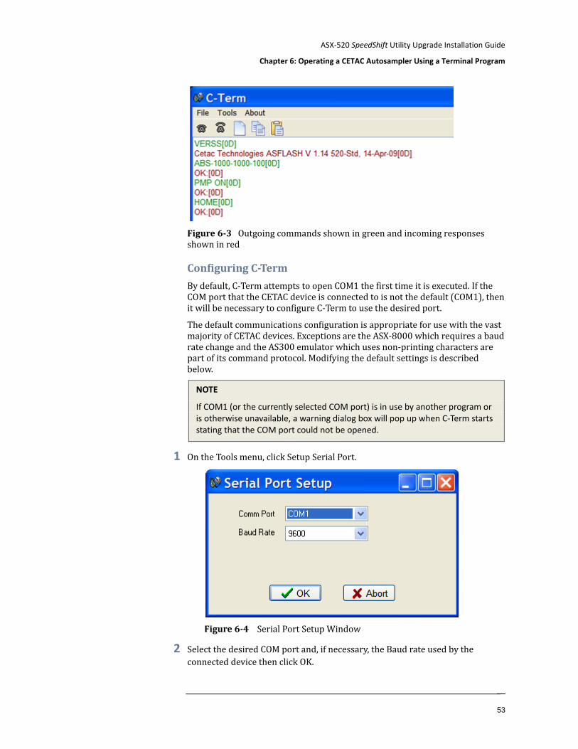
Figure 6-3 Outgoing commands shown in green and incoming responses shown in red
Configuring C-Term
By default, C-Term attempts to open COM1 the first time it is executed. If the COM port that the CETAC device is connected to is not the default (COM1), then it will be necessary to configure C-Term to use the desired port.
The default communications configuration is appropriate for use with the vast majority of CETAC devices. Exceptions are the ASX-8000 which requires a baud rate change and the AS300 emulator which uses non-printing characters are part of its command protocol. Modifying the default settings is described below.
NOTE
If COM1 (or the currently selected COM port) is in use by another program or is otherwise unavailable, a warning dialog box will pop up when C-Term starts stating that the COM port could not be opened.
1 On the Tools menu, click Setup Serial Port.
Figure 6-4 Serial Port Setup Window
2 Select the desired COM port and, if necessary, the Baud rate used by the connected device then click OK.
ASX-520 SpeedShift Utility Upgrade Installation Guide
54
The window will close and the settings will be saved. These new settings will be applied immediately and used thereafter unless changed again.
NOTE
All ASX-520 series autosamplers communicate at 9600 baud (which is the default.)
NOTE
Only installed COM ports, including USB virtual COM ports, will appear in the Comm Port menu.
Setting Preferences
If desired, the size of the scrollback buffer or the color of the outgoing and incoming texts can be changed (to work around color blindness, for example).
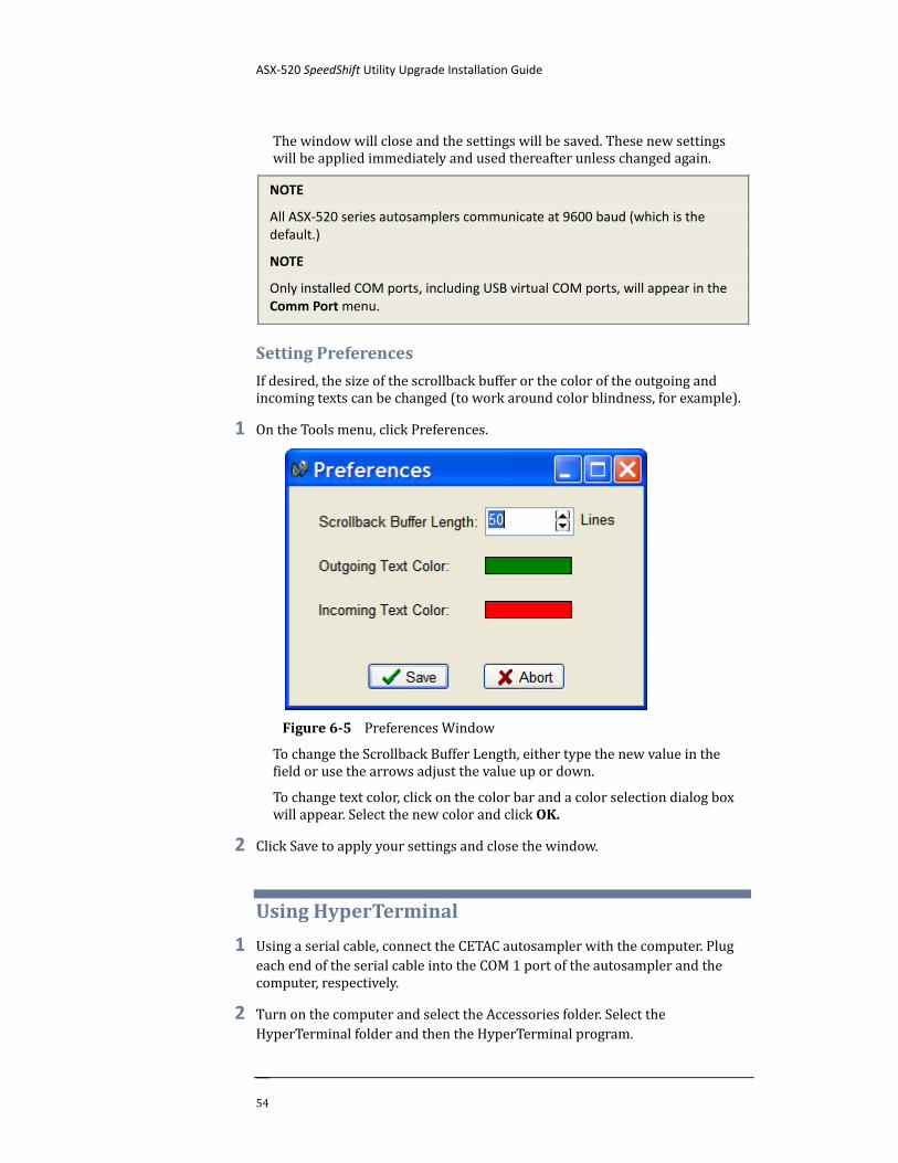
1 On the Tools menu, click Preferences.
Figure 6-5 Preferences Window
To change the Scrollback Buffer Length, either type the new value in the field or use the arrows adjust the value up or down.
To change text color, click on the color bar and a color selection dialog box will appear. Select the new color and click OK.
2 Click Save to apply your settings and close the window.
Using HyperTerminal
1 Using a serial cable, connect the CETAC autosampler with the computer. Plug each end of the serial cable into the COM 1 port of the autosampler and the computer, respectively.
2 Turn on the computer and select the Accessories folder. Select the HyperTerminal folder and then the HyperTerminal program.
ASX-520 SpeedShift Utility Upgrade Installation Guide
Chapter 6: Operating a CETAC Autosampler Using a Terminal Program
55
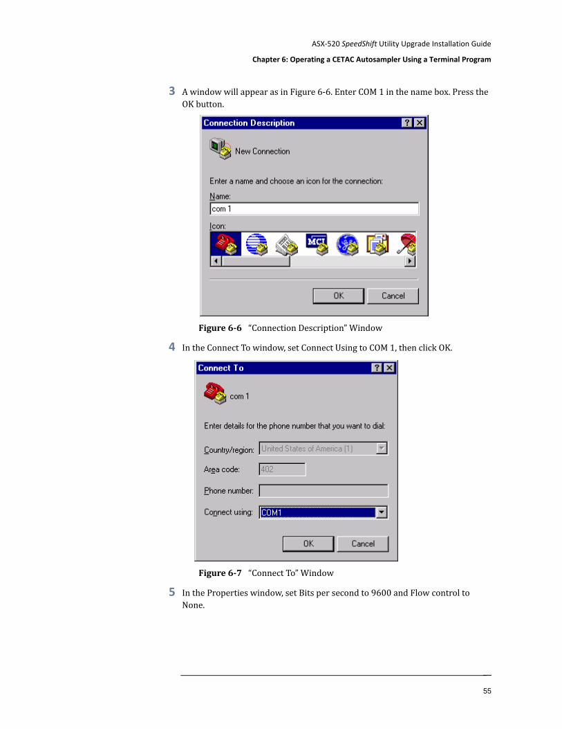
3 A window will appear as in Figure 6-6. Enter COM 1 in the name box. Press the OK button.
Figure 6-6 “Connection Description” Window
4 In the Connect To window, set Connect Using to COM 1, then click OK.
Figure 6-7 “Connect To” Window
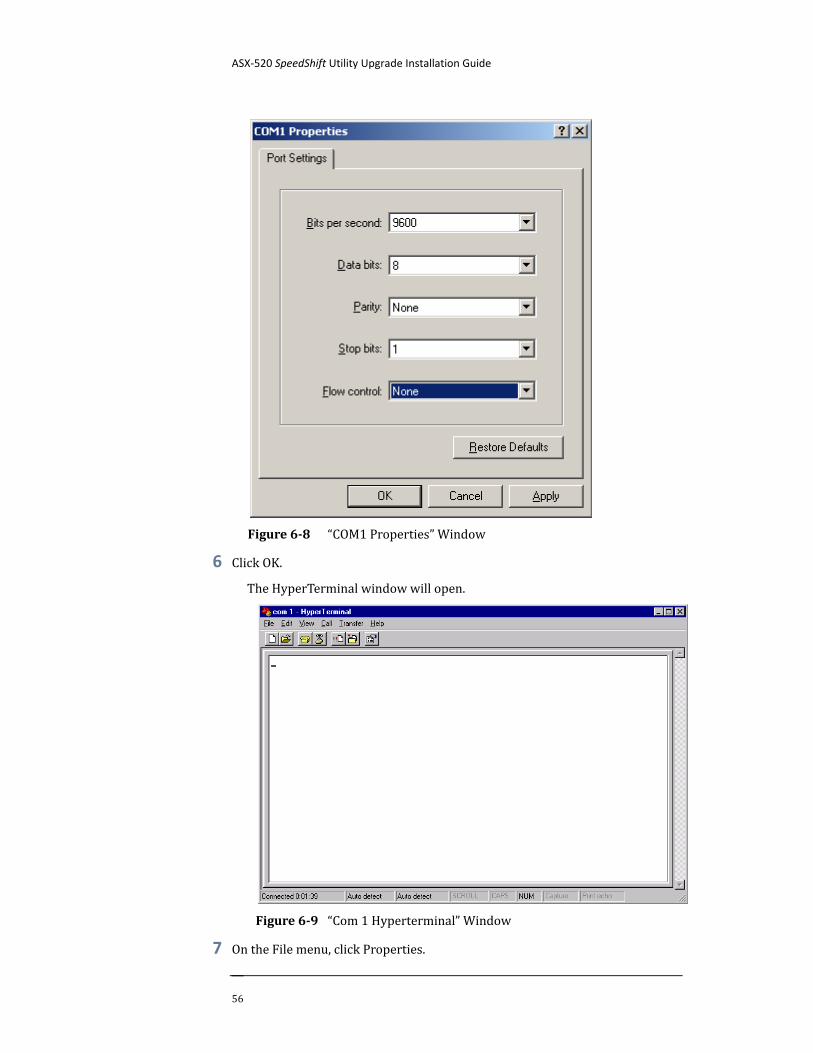
5 In the Properties window, set Bits per second to 9600 and Flow control to None.
ASX-520 SpeedShift Utility Upgrade Installation Guide
56
Figure 6-8 “COM1 Properties” Window
6 Click OK.
The HyperTerminal window will open.
Figure 6-9 “Com 1 Hyperterminal” Window
7 On the File menu, click Properties.
ASX-520 SpeedShift Utility Upgrade Installation Guide
Chapter 6: Operating a CETAC Autosampler Using a Terminal Program
57
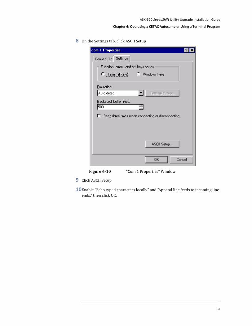
8 On the Settings tab, click ASCII Setup
Figure 6-10 “Com 1 Properties” Window
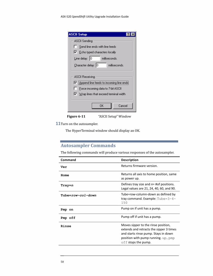
9 Click ASCII Setup.
10 Enable “Echo typed characters locally” and “Append line feeds to incoming line ends,” then click OK.
ASX-520 SpeedShift Utility Upgrade Installation Guide
58
Figure 6-11 “ASCII Setup” Window
11 Turn on the autosampler.
The HyperTerminal window should display an OK.
Autosampler Commands The following commands will produce various responses of the autosampler.
Command Description
Ver Returns firmware version.
Home Returns all axis to home position, same as power up.
Tray=n Defines tray size and n= #of positions. Legal values are 21, 24, 40, 60, and 90.
Tube=row-col-down Tube=row-column-down as defined by tray command. Example: Tube=3-4-150
Pmp on Pump on if unit has a pump.
Pmp off Pump off if unit has a pump.
Rinse Moves sipper to the rinse position, extends and retracts the sipper 3 times and starts rinse pump. Stays in down position with pump running. up,pmp off stops the pump.
ASX-520 SpeedShift Utility Upgrade Installation Guide
Chapter 6: Operating a CETAC Autosampler Using a Terminal Program
59
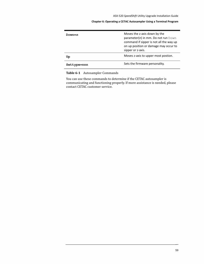
Down=n Moves the z-axis down by the parameter(n) in mm. Do not run Down command if sipper is not all the way up on up position or damage may occur to sipper or z-axis.
Up Moves z-axis to upper most postion.
Settype=nnn Sets the firmware personality.
Table 6-1 Autosampler Commands
You can use these commands to determine if the CETAC autosampler is communicating and functioning properly. If more assistance is needed, please contact CETAC customer service.
Manual Part Number 480174 Rev 3a Printed in USA