Embed Size (px)
Citation preview

8/13/2019 Asus P5E Motherboard User Guide
http://slidepdf.com/reader/full/asus-p5e-motherboard-user-guide 1/174
M o
t h
e r b o a r d
P5E
8/13/2019 Asus P5E Motherboard User Guide
http://slidepdf.com/reader/full/asus-p5e-motherboard-user-guide 2/174
ii
E3392
First Edition V1
September 2007
Copyright © 2007 ASUSTeK COMPUTER INC. All Rights Reserved.
No part of this manual, including the products and software described in it, may be reproduced,transmitted, transcribed, stored in a retrieval system, or translated into any language in any form or by anymeans, except documentation kept by the purchaser for backup purposes, without the express writtenpermission of ASUSTeK COMPUTER INC. (“ASUS”).
Product warranty or service will not be extended if: (1) the product is repaired, modied or altered, unless
such repair, modication of alteration is authorized in writing by ASUS; or (2) the serial number of theproduct is defaced or missing.
ASUS PROVIDES THIS MANUAL “AS IS” WITHOUT WARRANTY OF ANY KIND, EITHER EXPRESSOR IMPLIED, INCLUDING BUT NOT LIMITED TO THE IMPLIED WARRANTIES OR CONDITIONS OFMERCHANTABILITY OR FITNESS FOR A PARTICULAR PURPOSE. IN NO EVENT SHALL ASUS, ITSDIRECTORS, OFFICERS, EMPLOYEES OR AGENTS BE LIABLE FOR ANY INDIRECT, SPECIAL,INCIDENTAL, OR CONSEQUENTIAL DAMAGES (INCLUDING DAMAGES FOR LOSS OF PROFITS,LOSS OF BUSINESS, LOSS OF USE OR DATA, INTERRUPTION OF BUSINESS AND THE LIKE),EVEN IF ASUS HAS BEEN ADVISED OF THE POSSIBILITY OF SUCH DAMAGES ARISING FROM ANYDEFECT OR ERROR IN THIS MANUAL OR PRODUCT.
SPECIFICATIONS AND INFORMATION CONTAINED IN THIS MANUAL ARE FURNISHED FORINFORMATIONAL USE ONLY, AND ARE SUBJECT TO CHANGE AT ANY TIME WITHOUT NOTICE,
AND SHOULD NOT BE CONSTRUED AS A COMMITMENT BY ASUS. ASUS ASSUMES NORESPONSIBILITY OR LIABILITY FOR ANY ERRORS OR INACCURACIES THAT MAY APPEAR IN THISMANUAL, INCLUDING THE PRODUCTS AND SOFTWARE DESCRIBED IN IT.
Products and corporate names appearing in this manual may or may not be registered trademarks orcopyrights of their respective companies, and are used only for identication or explanation and to theowners’ benet, without intent to infringe.
8/13/2019 Asus P5E Motherboard User Guide
http://slidepdf.com/reader/full/asus-p5e-motherboard-user-guide 3/174
iii
Contents
Notices ....................................................................................................... viii
Safety information ...................................................................................... ix
About this guide .......................................................................................... x
P5E specications summary .................................................................... xii
Chapter 1: Product introduction
1.1 Welcome! ...................................................................................... 1-1
1.2 Package contents......................................................................... 1-1
1.3 Special features............................................................................ 1-2
1.3.1 Product highlights ........................................................... 1-2
1.3.2 ASUS AI Lifestyle unique features .................................. 1-41.3.3 ASUS Exclusive Overclocking Features ......................... 1-7
Chapter 2: Hardware information
2.1 Before you proceed ..................................................................... 2-1
Onboard LED ................................................................................. 2-1
2.2 Motherboard overview ................................................................. 2-2
2.2.1 Placement direction ........................................................ 2-2
2.2.2 Screw holes .................................................................... 2-22.2.3 Motherboard layout ......................................................... 2-3
2.2.4 Audio card layout ............................................................ 2-3
2.2.5 Layout contents ............................................................... 2-4
2.3 Central Processing Unit (CPU) ................................................... 2-6
2.3.1 Installing the CPU ........................................................... 2-7
2.3.2 Installing the CPU heatsink and fan ................................ 2-9
2.3.3 Uninstalling the CPU heatsink and fan ..........................2-112.3.4 Installing the optional fans ............................................ 2-13
2.4 System memory ......................................................................... 2-14
2.4.1 Overview ....................................................................... 2-14
2.4.2 Memory congurations .................................................. 2-15
2.4.3 Installing a DIMM .......................................................... 2-18
2.4.4 Removing a DIMM ........................................................ 2-18
2.5 Expansion slots.......................................................................... 2-19
2.5.1 Installing an expansion card ......................................... 2-19
2.5.2 Conguring an expansion card ..................................... 2-19
2.5.3 Interrupt assignments ................................................... 2-20
8/13/2019 Asus P5E Motherboard User Guide
http://slidepdf.com/reader/full/asus-p5e-motherboard-user-guide 4/174
iv
Contents
2.5.4 PCI slots ........................................................................ 2-21
2.5.5 PCI Express x1 slots ..................................................... 2-21
2.5.6 PCI Express 2.0 x16 slots ............................................. 2-21
2.6 Switch.......................................................................................... 2-22
2.7 Audio card installation .............................................................. 2-23
2.7.1 Audio card Installation ................................................... 2-23
2.8 Connectors ................................................................................. 2-24
2.8.1 Rear panel connectors .................................................. 2-24
2.8.2 Internal connectors ....................................................... 2-26
Chapter 3: Powering up3.1 Starting up for the rst time........................................................ 3-1
3.2 Turning off the computer ............................................................. 3-2
3.2.1 Using the OS shut down function .................................... 3-2
3.2.2 Using the dual function power switch .............................. 3-2
Chapter 4: BIOS setup
4.1 Managing and updating your BIOS ............................................ 4-1
4.1.1 ASUS Update utility ........................................................ 4-14.1.2 Creating a bootable oppy disk ....................................... 4-4
4.1.3 ASUS EZ Flash 2 utility ................................................... 4-5
4.1.4 AFUDOS utility ................................................................ 4-6
4.1.5 ASUS CrashFree BIOS 3 utility ...................................... 4-8
4.2 BIOS setup program .................................................................... 4-9
4.2.1 BIOS menu screen ........................................................ 4-10
4.2.2 Menu bar ....................................................................... 4-104.2.3 Navigation keys ............................................................. 4-10
4.2.4 Menu items ....................................................................4-11
4.2.5 Sub-menu items .............................................................4-11
4.2.6 Conguration elds ........................................................4-11
4.2.7 Pop-up window ..............................................................4-11
4.2.8 Scroll bar ........................................................................4-11
4.2.9 General help ..................................................................4-11
4.3 Main menu .................................................................................. 4-12
4.3.1 System Time ................................................................. 4-12
4.3.2 System Date ................................................................. 4-12

8/13/2019 Asus P5E Motherboard User Guide
http://slidepdf.com/reader/full/asus-p5e-motherboard-user-guide 5/174
v
Contents
4.3.3 Legacy Diskette A ..............................................................................4-12
4.3.4 Language ...................................................................... 4-12
4.3.5 SATA 1-6 ....................................................................... 4-13
4.3.6 SATA Conguration ....................................................... 4-14
4.3.7 AHCI Conguration ....................................................... 4-15
4.3.8 System Information ....................................................... 4-16
4.4 Ai Tweaker menu ........................................................................ 4-17
4.4.1 Ai Overclock Tuner ........................................................ 4-17
4.4.2 CPU Ratio Control ........................................................ 4-18
4.4.3 FSB Strap to North Bridge ............................................ 4-18
4.4.4 DRAM Frequency ......................................................... 4-19
4.4.5 DRAM Timing Control ................................................... 4-19
4.4.7 DRAM Static Read Control ........................................... 4-20
4.4.8 Transaction Booster ...................................................... 4-20
4.4.6 DRAM Command Rate ................................................. 4-20
4.4.9 CPU Spread Spectrum ................................................. 4-22
4.4.10 PCIE Spread Spectrum ................................................. 4-22
4.5 Advanced menu ......................................................................... 4-234.5.1 CPU Conguration ........................................................ 4-23
4.5.2 Chipset .......................................................................... 4-25
4.5.3 Onboard Device Conguration ...................................... 4-26
4.5.4 USB Conguration ........................................................ 4-27
4.5.5 PCIPnP ......................................................................... 4-28
4.6 Power menu ................................................................................ 4-29
4.6.1 Suspend Mode [Auto] ................................................... 4-294.6.2 Repost Video on S3 Resume ........................................ 4-29
4.6.3 ACPI 2.0 Support .......................................................... 4-29
4.6.4 ACPI APIC Support ....................................................... 4-29
4.6.5 APM Conguration ........................................................ 4-30
4.6.6 Hardware Monitor ......................................................... 4-31
4.7 Boot menu .................................................................................. 4-33
4.7.1 Boot Device Priority ...................................................... 4-33
4.7.2 Boot Settings Conguration .......................................... 4-34
4.7.3 Security ......................................................................... 4-35

8/13/2019 Asus P5E Motherboard User Guide
http://slidepdf.com/reader/full/asus-p5e-motherboard-user-guide 6/174
vi
Contents
4.8 Tools menu ................................................................................. 4-37
4.8.1 ASUS EZ Flash 2 .......................................................... 4-37
4.8.2 ASUS O.C. Prole ......................................................... 4-38
4.8.3 Ai Net 2 ......................................................................... 4-39
4.9 Exit menu .................................................................................... 4-40
Chapter 5: Software support
5.1 Installing an operating system ................................................... 5-1
5.2 Support DVD information ............................................................ 5-1
5.2.1 Running the support DVD ............................................... 5-1
5.2.2 Drivers menu ................................................................... 5-25.2.3 Utilities menu .................................................................. 5-3
5.2.4 Make Disk menu ............................................................. 5-5
5.2.5 Manuals menu ................................................................ 5-6
5.2.6 ASUS Contact information .............................................. 5-6
5.2.7 Other information ............................................................ 5-7
5.3 Software information ................................................................... 5-9
5.3.1 ASUS MyLogo3™ ............................................................ 5-9
5.3.2 AI NET 2.........................................................................5-11
5.3.3 AI Audio 2 (SoundMAX® High Denition Audio utility) ... 5-12
5.3.4 ASUS PC Probe II ......................................................... 5-21
5.3.5 ASUS AI Suite ............................................................... 5-27
5.3.6 ASUS AI Gear 3 ............................................................ 5-29
5.3.7 ASUS AI Nap ................................................................ 5-30
5.3.8 ASUS Q-Fan 2 .............................................................. 5-31
5.3.9 ASUS AI Booster ........................................................... 5-32
5.3.10 ASUS AI Direct Link ...................................................... 5-33
5.4 RAID congurations .................................................................. 5-35
5.4.1 RAID denitions ............................................................ 5-35
5.4.2 Installing Serial ATA hard disks ..................................... 5-36
5.4.3 Intel® RAID congurations ............................................. 5-36
5.5 Creating a RAID driver disk ....................................................... 5-44
5.5.1 Creating a RAID driver disk without entering the OS .... 5-445.5.2 Creating a RAID/SATA driver disk in Windows® ............ 5-44
8/13/2019 Asus P5E Motherboard User Guide
http://slidepdf.com/reader/full/asus-p5e-motherboard-user-guide 7/174
vii
Chapter 6: ATI® CrossFire™ technology support
6.1 Overview ....................................................................................... 6-1
6.1.1 Requirements .................................................................. 6-1
6.1.2 Before you begin ............................................................. 6-1
6.2 Installing CrossFire™ graphics cards ....................................... 6-2
6.3 Software information ................................................................... 6-5
6.3.1 Installing the device drivers ............................................. 6-5
6.3.2 Using the Catalyst™ Control Center ............................... 6-7
Appendix: CPU features
A.1 Intel®
EM64T ..................................................................................A-1A.2 Enhanced Intel SpeedStep® Technology (EIST) ........................A-1
A.2.1 System requirements ......................................................A-1
A.2.2 Using the EIST ................................................................A-2
A.3 Intel® Hyper-Threading Technology ...........................................A-3
Using the Hyper-Threading Technology ........................................A-3
A.4 Debug Code Table ........................................................................A-4
8/13/2019 Asus P5E Motherboard User Guide
http://slidepdf.com/reader/full/asus-p5e-motherboard-user-guide 8/174
viii
Notices
Federal Communications Commission Statement
This device complies with Part 15 of the FCC Rules. Operation is subject to the
following two conditions:• This device may not cause harmful interference, and
• This device must accept any interference received including interference that
may cause undesired operation.
This equipment has been tested and found to comply with the limits for aClass B digital device, pursuant to Part 15 of the FCC Rules. These limits are
designed to provide reasonable protection against harmful interference in a
residential installation. This equipment generates, uses and can radiate radio
frequency energy and, if not installed and used in accordance with manufacturer’sinstructions, may cause harmful interference to radio communications. However,
there is no guarantee that interference will not occur in a particular installation. If
this equipment does cause harmful interference to radio or television reception,which can be determined by turning the equipment off and on, the user is
encouraged to try to correct the interference by one or more of the following
measures:
• Reorient or relocate the receiving antenna.
• Increase the separation between the equipment and receiver.
• Connect the equipment to an outlet on a circuit different from that to which thereceiver is connected.
• Consult the dealer or an experienced radio/TV technician for help.
Canadian Department of Communications Statement
This digital apparatus does not exceed the Class B limits for radio noise emissions
from digital apparatus set out in the Radio Interference Regulations of theCanadian Department of Communications.
This class B digital apparatus complies with Canadian ICES-003.
The use of shielded cables for connection of the monitor to the graphics card isrequired to assure compliance with FCC regulations. Changes or modications
to this unit not expressly approved by the party responsible for compliancecould void the user’s authority to operate this equipment.

8/13/2019 Asus P5E Motherboard User Guide
http://slidepdf.com/reader/full/asus-p5e-motherboard-user-guide 9/174
ix
Safety information
Electrical safety
• To prevent electrical shock hazard, disconnect the power cable from theelectrical outlet before relocating the system.
• When adding or removing devices to or from the system, ensure that the
power cables for the devices are unplugged before the signal cables are
connected. If possible, disconnect all power cables from the existing system
before you add a device.
• Before connecting or removing signal cables from the motherboard, ensurethat all power cables are unplugged.
• Seek professional assistance before using an adpater or extension cord.
These devices could interrupt the grounding circuit.
• Make sure that your power supply is set to the correct voltage in your area.
If you are not sure about the voltage of the electrical outlet you are using,
contact your local power company.
• If the power supply is broken, do not try to x it by yourself. Contact aqualied service technician or your retailer.
Operation safety
• Before installing the motherboard and adding devices on it, carefully read all
the manuals that came with the package.
• Before using the product, make sure all cables are correctly connected and the
power cables are not damaged. If you detect any damage, contact your dealer
immediately.
• To avoid short circuits, keep paper clips, screws, and staples away fromconnectors, slots, sockets and circuitry.
• Avoid dust, humidity, and temperature extremes. Do not place the product inany area where it may become wet.
• Place the product on a stable surface.
• If you encounter technical problems with the product, contact a qualiedservice technician or your retailer.
This symbol of the crossed out wheeled bin indicates that the product (electricaland electronic equipment, and mercury-containing button cell battery) shouldnot be placed in municipal waste. Check local regulations for disposal of
electronic products.
8/13/2019 Asus P5E Motherboard User Guide
http://slidepdf.com/reader/full/asus-p5e-motherboard-user-guide 10/174
x
About this guideThis user guide contains the information you need when installing and conguringthe motherboard.
How this guide is organized
This guide contains the following parts:
• Chapter 1: Product introduction
This chapter describes the features of the motherboard and the newtechnology it supports.
• Chapter 2: Hardware information
This chapter lists the hardware setup procedures that you have to perform
when installing system components. It includes description of the switches,
jumpers, and connectors on the motherboard.• Chapter 3: Powering up
This chapter describes the power up sequence and ways of shutting down
the system.
• Chapter 4: BIOS setup
This chapter tells how to change system settings through the BIOS Setup
menus. Detailed descriptions of the BIOS parameters are also provided.
• Chapter 5: Software supportThis chapter describes the contents of the support DVD that comes with themotherboard package.
• Chapter 6: ATI CrossFire™ support
This chapter describes the ATI CrossFire™ feature and shows the graphics
card installation procedures.
• Appendix: CPU features
The Appendix describes the CPU features and technologies that the
motherboard supports.
Where to nd more information
Refer to the following sources for additional information and for product and
software updates.
1. ASUS websites
The ASUS website provides updated information on ASUS hardware and
software products. Refer to the ASUS contact information.
2. Optional documentation
Your product package may include optional documentation, such as warranty
yers, that may have been added by your dealer. These documents are notpart of the standard package.
8/13/2019 Asus P5E Motherboard User Guide
http://slidepdf.com/reader/full/asus-p5e-motherboard-user-guide 11/174
xi
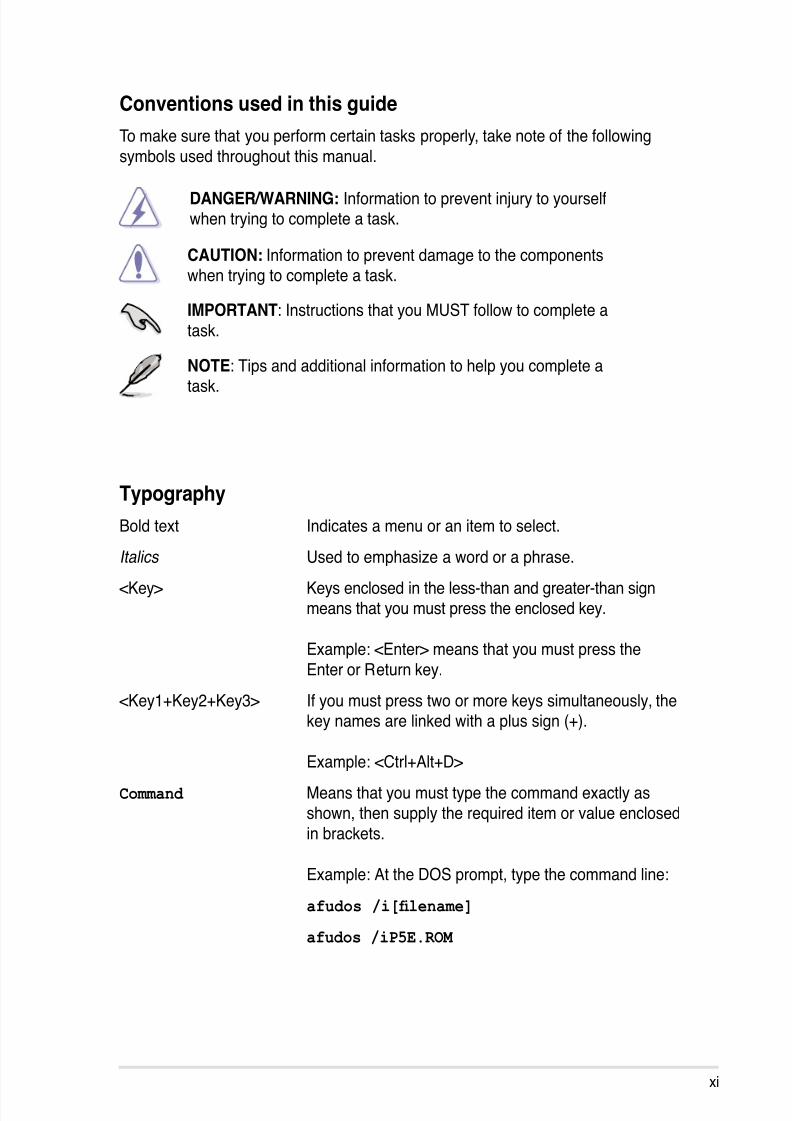
Conventions used in this guide
To make sure that you perform certain tasks properly, take note of the following
symbols used throughout this manual.
Typography
Bold text Indicates a menu or an item to select.
Italics Used to emphasize a word or a phrase.<Key> Keys enclosed in the less-than and greater-than sign
means that you must press the enclosed key.
Example: <Enter> means that you must press the
Enter or Return key.
<Key1+Key2+Key3> If you must press two or more keys simultaneously, thekey names are linked with a plus sign (+).
Example: <Ctrl+Alt+D>
Command Means that you must type the command exactly asshown, then supply the required item or value enclosed
in brackets.
Example: At the DOS prompt, type the command line:
afudos /i[lename]
afudos /iP5E.ROM
DANGER/WARNING: Information to prevent injury to yourselfwhen trying to complete a task.
CAUTION: Information to prevent damage to the componentswhen trying to complete a task.
NOTE: Tips and additional information to help you complete atask.
IMPORTANT: Instructions that you MUST follow to complete a
task.
8/13/2019 Asus P5E Motherboard User Guide
http://slidepdf.com/reader/full/asus-p5e-motherboard-user-guide 12/174
xii
P5E specications summary
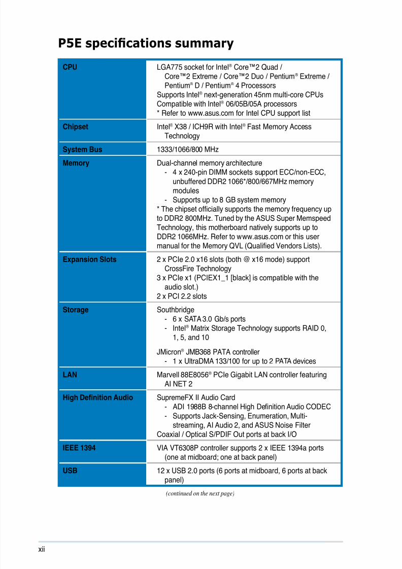
CPU LGA775 socket for Intel® Core™2 Quad /Core™2 Extreme / Core™2 Duo / Pentium® Extreme /Pentium® D / Pentium® 4 Processors
Supports Intel® next-generation 45nm multi-core CPUsCompatible with Intel® 06/05B/05A processors* Refer to www.asus.com for Intel CPU support list
Chipset Intel® X38 / ICH9R with Intel® Fast Memory AccessTechnology
System Bus 1333/1066/800 MHz
Memory Dual-channel memory architecture- 4 x 240-pin DIMM sockets support ECC/non-ECC,
unbuffered DDR2 1066*/800/667MHz memory
modules- Supports up to 8 GB system memory
* The chipset ofcially supports the memory frequency upto DDR2 800MHz. Tuned by the ASUS Super Memspeed
Technology, this motherboard natively supports up toDDR2 1066MHz. Refer to www.asus.com or this usermanual for the Memory QVL (Qualied Vendors Lists).
Expansion Slots 2 x PCIe 2.0 x16 slots (both @ x16 mode) supportCrossFire Technology
3 x PCIe x1 (PCIEX1_1 [black] is compatible with the
audio slot.)2 x PCI 2.2 slots
Storage Southbridge
- 6 x SATA 3.0 Gb/s ports- Intel® Matrix Storage Technology supports RAID 0,
1, 5, and 10
JMicron® JMB368 PATA controller- 1 x UltraDMA 133/100 for up to 2 PATA devices
LAN Marvell 88E8056® PCIe Gigabit LAN controller featuringAI NET 2
High Denition Audio SupremeFX II Audio Card- ADI 1988B 8-channel High Denition Audio CODEC
- Supports Jack-Sensing, Enumeration, Multi-streaming, AI Audio 2, and ASUS Noise Filter
Coaxial / Optical S/PDIF Out ports at back I/O
IEEE 1394 VIA VT6308P controller supports 2 x IEEE 1394a ports(one at midboard; one at back panel)
USB 12 x USB 2.0 ports (6 ports at midboard, 6 ports at backpanel)
(continued on the next page)
8/13/2019 Asus P5E Motherboard User Guide
http://slidepdf.com/reader/full/asus-p5e-motherboard-user-guide 13/174
xiii
P5E specications summary
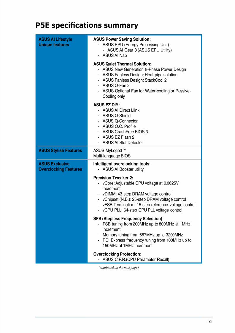
ASUS AI Lifestyle
Unique features
ASUS Power Saving Solution:
- ASUS EPU (Energy Processing Unit)- ASUS AI Gear 3 (ASUS EPU Utility)
- ASUS AI Nap
ASUS Quiet Thermal Solution: - ASUS New Generation 8-Phase Power Design- ASUS Fanless Design: Heat-pipe solution- ASUS Fanless Design: StackCool 2- ASUS Q-Fan 2- ASUS Optional Fan for Water-cooling or Passive-
Cooling only
ASUS EZ DIY:
- ASUS AI Direct Llink- ASUS Q-Shield- ASUS Q-Connector- ASUS O.C. Prole - ASUS CrashFree BIOS 3
- ASUS EZ Flash 2- ASUS AI Slot Detector
ASUS Stylish Features ASUS MyLogo3™Multi-language BIOS
ASUS ExclusiveOverclocking Features
Intelligent overclocking tools:
- ASUS AI Booster utility
Precision Tweaker 2:- vCore: Adjustable CPU voltage at 0.0625V
increment- vDIMM: 43-step DRAM voltage control
- vChipset (N.B.): 25-step DRAM voltage control- vFSB Termination: 15-step reference voltage control- vCPU PLL: 64-step CPU PLL voltage control
SFS (Stepless Frequency Selection) - FSB tuning from 200MHz up to 800MHz at 1MHz
increment- Memory tuning from 667MHz up to 3200MHz - PCI Express frequency tuning from 100MHz up to
150MHz at 1MHz increment
Overclocking Protection: - ASUS C.P.R.(CPU Parameter Recall)
(continued on the next page)
8/13/2019 Asus P5E Motherboard User Guide
http://slidepdf.com/reader/full/asus-p5e-motherboard-user-guide 14/174
xiv
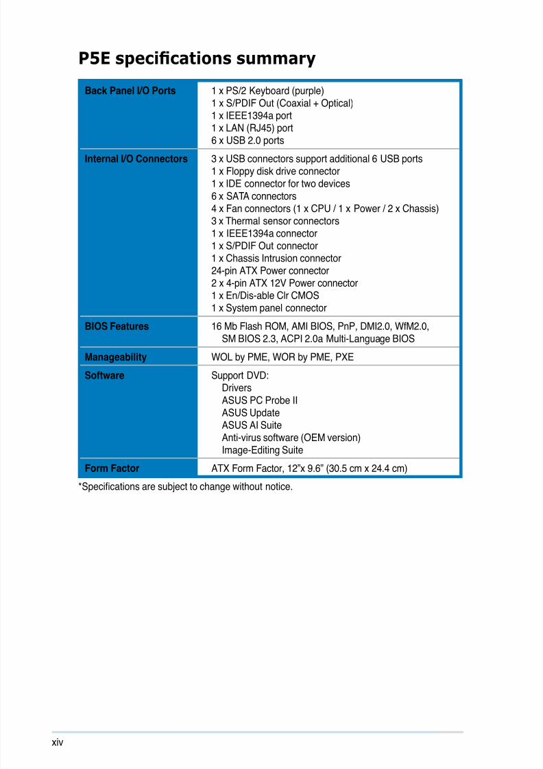
Back Panel I/O Ports 1 x PS/2 Keyboard (purple)1 x S/PDIF Out (Coaxial + Optical)1 x IEEE1394a port
1 x LAN (RJ45) port6 x USB 2.0 ports
Internal I/O Connectors 3 x USB connectors support additional 6 USB ports1 x Floppy disk drive connector1 x IDE connector for two devices
6 x SATA connectors4 x Fan connectors (1 x CPU / 1 x Power / 2 x Chassis)3 x Thermal sensor connectors1 x IEEE1394a connector1 x S/PDIF Out connector
1 x Chassis Intrusion connector24-pin ATX Power connector2 x 4-pin ATX 12V Power connector1 x En/Dis-able Clr CMOS1 x System panel connector
BIOS Features 16 Mb Flash ROM, AMI BIOS, PnP, DMI2.0, WfM2.0,SM BIOS 2.3, ACPI 2.0a Multi-Language BIOS
Manageability WOL by PME, WOR by PME, PXE
Software Support DVD:
DriversASUS PC Probe IIASUS UpdateASUS AI SuiteAnti-virus software (OEM version)Image-Editing Suite
Form Factor ATX Form Factor, 12”x 9.6” (30.5 cm x 24.4 cm)
*Specications are subject to change without notice.
P5E specications summary

8/13/2019 Asus P5E Motherboard User Guide
http://slidepdf.com/reader/full/asus-p5e-motherboard-user-guide 15/174
1Productintroduction
This chapter describes the motherboard
features and the new technologiesit supports.
8/13/2019 Asus P5E Motherboard User Guide
http://slidepdf.com/reader/full/asus-p5e-motherboard-user-guide 16/174
ASUS P5E
Chapter summary 11.1 Welcome! ...................................................................................... 1-1
1.2 Package contents......................................................................... 1-1
1.3 Special features ............................................................................ 1-2
8/13/2019 Asus P5E Motherboard User Guide
http://slidepdf.com/reader/full/asus-p5e-motherboard-user-guide 17/174
ASUS P5E 1-1
1.1 Welcome!
Thank you for buying an ASUS® P5E motherboard!
The motherboard delivers a host of new features and latest technologies, making itanother standout in the long line of ASUS quality motherboards!
Before you start installing the motherboard, and hardware devices on it, check the
items in your package with the list below.
If any of the above items is damaged or missing, contact your retailer.
1.2 Package contents
Check your motherboard package for the following items.
Motherboard ASUS P5E
I/O modules 1 x Multi-function module (1-port IEEE 1394a
module and 2-port USB 2.0 module)
Cables 1 x Serial ATA power cable for 2 devices
6 x Serial ATA signal cable
1 x Ultra DMA 133/100 cable
1 x Floppy disk drive cable
Accessories ASUS Q-Shield (Advance I/O shield)ASUS Optional Fan
SupremeFX II Audio Card1 x ASUS Q-Connector Kit (USB, 1394, system
panel; Retail version only)
Application DVD ASUS motherboard Support DVD
Documentation User guide
8/13/2019 Asus P5E Motherboard User Guide
http://slidepdf.com/reader/full/asus-p5e-motherboard-user-guide 18/174
1-2 Chapter 1: Product Introduction
1.3 Special features
1.3.1 Product highlights
Green ASUS
This motherboard and its packaging comply with the European Union’s Restrictionon the use of Hazardous Substances (RoHS). This is in line with the ASUS visionof creating environment-friendly and recyclable products/packaging to safeguard
consumers’ health while minimizing the impact on the environment.
Intel® Core™ 2 Quad Processor ready
This motherboard supports the latest Intel® Core™ 2 Quad processors in the
LGA775 package and Intel’s next-generation 45nm multi-core processors.It is excellent for multi-tasking, multi-media and enthusiastic gamers with
1333/1066/800 MHz FSB. Intel® Core™ 2 Quad processor is one of the most
powerful CPU in the world. See page 2-9 for details.
Intel® Core™2 Duo/ Intel® Core™2 Extreme CPU support
This motherboard supports the latest Intel® Core™2 processor in the LGA775
package and Intel’s next-generation 45nm multi-core processors. With the newIntel® Core™ microarchitecture technology and 1333/1066/800 MHz FSB, theIntel® Core™2 is one of the most powerful and energy efcient CPUs in the world.See page 2-9 for details.
Intel® X38 Chipset
The Intel® X38 Express Chipset is the latest chipset designed to support 8GB of
dual-channel DDR2 800/667 MHz memory architecture, 1333/1066/800 FSB (Front
Side Bus), dual PCI Express 2.0 x16 graphics and multi-core CPUs. It especiallyincludes Intel® Fast Memory Access technology that signicantly optimizes the useof available memory bandwidth and reduces the latency of the memory accesses.
PCIe 2.0
This motherboard supports the latest PCIe 2.0 device for twice the current speedand bandwidth. This enhances system performance while still providing backward
compatibility to PCIe 1.0 devices.
8/13/2019 Asus P5E Motherboard User Guide
http://slidepdf.com/reader/full/asus-p5e-motherboard-user-guide 19/174
ASUS P5E 1-3
Native DDR2 1066 memory support
To attain top performance, ASUS engineers have successfully unleashed the
true potential of DDR2 memory. While in DDR2 1066 mode, ASUS’s exclusivetechnology offers a choice of FSB 1333, providing great performance for 3D
graphics and other memory demanding applications. See page 2-19 for details.
Dual-channel DDR2 800 memory support
The motherboard supports DDR2 memory that features data transfer rates of
800/667 MHz to meet the higher bandwidth requirements of the latest 3D graphics,multimedia, and Internet applications. The dual-channel DDR2 architecture
doubles the bandwidth of your system memory to boost system performance,eliminating bottlenecks with peak bandwidths of up to 12.8 GB/s. Furthermore, this
motherboard does not restrict the memory size across two channels. Users mayinstall different memory size DIMMs into the two channels and enjoy dual-channeland single-channel functions at the same time. This new feature optimizes the useof available memory size. See page 2-19 for details.
ASUS Super Memspeed Technology
To attain top performance, ASUS has managed to break through current FSBand DRAM ratio proportions by utilizing Super Memspeed Technology–the latesttechnology that provides even more precise overclocking options to unleash the
true potential of DDR2 memory. The DDR2 Mode maximizes system performanceby eliminating the bottleneck when overclocking both the CPU and memory–providing great performance for 3D graphics and other memory demandingapplications. See page 2-19 for details.
Serial ATA 3.0 Gb/s technology
This motherboard supports the next-generation hard drives based on the Serial
ATA (SATA) 3Gb/s storage specication, delivering enhanced scalability anddoubling the bus bandwidth for high-speed data retrieval and saves. See page
2-29 for details.
IEEE 1394a support
The IEEE 1394a interface provides high speed digital interface for audio/video
appliances such as digital television, digital video camcorders, storage peripherals
& other PC portable devices. See pages 2-26 and 2-30 for details.
8/13/2019 Asus P5E Motherboard User Guide
http://slidepdf.com/reader/full/asus-p5e-motherboard-user-guide 20/174
1-4 Chapter 1: Product Introduction
High Denition Audio
Enjoy high-end sound quality on your PC! The onboard 8-channel HD audio (High
Denition Audio, previously codenamed Azalia) CODEC enables high-quality192KHz/24-bit audio output, jack-sensing feature, retasking functions, and multi-streaming technology that simultaneously sends different audio streams to different
destinations. You can now talk to your partners on the headphones while playing
multi-channel network games. See pages 2-25 and 2-26 for details.
1.3.2 ASUS AI Lifestyle unique features
ASUS Power Saving Solution
ASUS Power Saving solution intelligently and automatically provides balancedcomputing power and energy consumption.
ASUS EPU
The ASUS EPU utilizes innovative technology to digitally monitor andtune the CPU power supply with improved VR responses in heavy or light
loadings. It automatically provides power for higher performance or improve
efciency by 7% when the PC is running low intensity applications. Working
together with AI Gear 3, this can help you attain the best possible powerefciency and energy savings up to 58.6% to help save the environment. Seepage 5-20 for details.
AI Nap
With AI Nap, the system can continue running at minimum power
consumption and noise when you are temporarily away. To wake up the
system and return to the OS environment, simply click the mouse or press a
key. See page 5-21 for details.
ASUS Quiet Thermal Solution
ASUS Quiet Thermal solution makes system more stable and enhances theoverclocking capability.
New Generation 8-Phase Power Design
The ASUS 8-Phase Power Design provides highly efcient operation to
generate less heat (at least 18°C (32.4°F)) than other conventional powersolutions. It reduces input ripple current and output ripple voltage, which
keeps CPU and power module from suffering the risk of high power stress.It has the advantages of quick transient response and stability, especially
benecial when CPU requires more current immediately under heavy loadingor overclocking mode.

8/13/2019 Asus P5E Motherboard User Guide
http://slidepdf.com/reader/full/asus-p5e-motherboard-user-guide 21/174
ASUS P5E 1-5
Q-Fan 2
ASUS Q-Fan 2 technology intelligently adjusts both CPU fan and chassis
fan speeds according to system loading to ensure quiet, cool and efcientoperation. See page 4-28 and 5-23 for details.
Fanless Design - Pure Copper Heat-pipe
The Heat Pipe design effectively directs the heat generated by the chipsets to
the heatsink near the back IO ports, where it can be carried away by existing
airow from CPU fan or bundled optional fan. The purpose of the innovativeheat pipe design on this motherboard is that the groundbreaking fanless
design does not have lifetime problems as a chipset fan does. Furthermore, itprovides options for users to install side-ow fan or passive cooler. The HeatPipe design is the most reliable fanless thermal solution to date.
DO NOT uninstall the heat-pipe by yourself. Doing so may bend the tubing andaffect the heat dissipation performance.
Optional Fan (for Water-Cooling or Passive-Cooling only)
The optional fan is specically designed to provide sufcient airow over the
CPU power modules and chipset area when water-cooling or passive-coolingis utilized, ensuring effective heat dissipation for the entire system. See page2-13 for details.
Gaming Level Audio Design: Supreme FX II
Supreme FX II delivers an excellent high denition audio experience to the gamersof ROG. The SupremeFX II features unique audio innovations for gamers to spot
enemies in 3D environment during game play. SupremeFX II also provides a
special tool to emphasize human voices in games to help make dialogues clearer.See page 2-24 for details.
AI Audio 2
AI Audio 2 creates a virtual center channel that expands the overall sound
eld without introducing a picket fencing effect. Preserving the dialogue orsolo performances with downmixing from multichannels will allow you toexperience true-to-life high quality audio.
Noise Filter
This feature detects repetitive and stationary noises (non-voice signals) like
computer fans, air conditioners, and other background noises then eliminates
it in the incoming audio stream while recording. See page 5-29 for details.
8/13/2019 Asus P5E Motherboard User Guide
http://slidepdf.com/reader/full/asus-p5e-motherboard-user-guide 22/174
1-6 Chapter 1: Product Introduction
ASUS EZ DIY
ASUS EZ DIY feature collection provides you easy ways to install computer
components, update the BIOS or back up your favorite settings.
ASUS AI Direct Link
AI Direct Link can easily and efciently transfer large amounts of data viathe network cable - saving up to 70% of the total time taken. With AI DirectLink, it becomes easy to backup or share large data les like movies or othermedia content. See page 5-30 for details.
ASUS Q-Shield
The specially designed ASUS Q-Shield does without the usual “ngers”-- making it convenient and easy to install. With better electric conductivity,it ideally protects your motherboard against static electricity and shields it
against Electronic Magnetic Interference (EMI).
ASUS Q-Connector
ASUS Q-Connector allows you to easily connect or disconnect the chassis
front panel cables to the motherboard. This unique module eliminates thetrouble of connecting the system panel cables one at a time and avoiding
wrong cable connections. See page 2-35 for details.
ASUS O.C. Prole
The motherboard features the ASUS O.C. Prole that allows users toconveniently store or load multiple BIOS settings. The BIOS settings can be
stored in the CMOS or a separate le, giving users freedom to share and
distribute their favorite settings. See page 4-35 for details.
ASUS CrashFree BIOS 3
The ASUS CrashFree BIOS 3 allows users to restore corrupted BIOS data
from a USB ash disk containing the BIOS le. See page 4-7 for details.
ASUS EZ Flash 2
EZ Flash 2 is a user-friendly BIOS update utility. Simply press the predenedhotkey to launch the utility and update the BIOS without entering the OS.
Update your BIOS easily without preparing a bootable diskette or using an
OS-based ash utility. See pages 4-4 and 4-34 for details.

8/13/2019 Asus P5E Motherboard User Guide
http://slidepdf.com/reader/full/asus-p5e-motherboard-user-guide 23/174
ASUS P5E 1-7
Smart Support DVD
It provides a checklist to allow the user to see which drivers are already
installed, as well as those that aren’t. When using ASUS PC Probe II, youcan easily see the critical parts of the computer.
ASUS MyLogo3™
This feature allows you to convert your favorite photo into a 256-color boot logo for
a more colorful and vivid image on your screen. See page 4-31 and 5-9 for details.
ASUS Multi-language BIOS
The multi-language BIOS allows you to select the language of your choice from theavailable options. The localized BIOS setup menu helps you congure your systemeasier and faster. See page 4-11 for details.
1.3.3 ASUS Exclusive Overclocking Features
AI Booster
The ASUS AI Booster allows you to overclock the CPU speed in Windows
environment without the hassle of booting the BIOS.
Precision Tweaker 2
Allows the user to adjust the NB Voltage, FSB termination Voltage, CPU PLL
Voltage and the DRAM Voltage in 0.02v steps to netune voltages to achieve themost precise setting for the ultimate customized overclocking conguration. Seepage 4-20 for details.
C.P.R. (CPU Parameter Recall)The C.P.R. feature of the motherboard BIOS allows automatic re-setting to the
BIOS default settings in case the system hangs due to overclocking. When the
system hangs due to overclocking, C.P.R. eliminates the need to open the systemchassis and clear the RTC data. Simply shut down and reboot the system, and the
BIOS automatically restores the CPU default setting for each parameter.

8/13/2019 Asus P5E Motherboard User Guide
http://slidepdf.com/reader/full/asus-p5e-motherboard-user-guide 24/174
1-8 Chapter 1: Product Introduction

8/13/2019 Asus P5E Motherboard User Guide
http://slidepdf.com/reader/full/asus-p5e-motherboard-user-guide 25/174
2Hardwareinformation
This chapter lists the hardware setup
procedures that you have to perform
when installing system components. Itincludes description of the jumpers and
connectors on the motherboard.

8/13/2019 Asus P5E Motherboard User Guide
http://slidepdf.com/reader/full/asus-p5e-motherboard-user-guide 26/174
ASUS P5E
Chapter summary 22.1 Before you proceed ..................................................................... 2-1
2.2 Motherboard overview ................................................................. 2-2
2.3 Central Processing Unit (CPU) ................................................... 2-6
2.4 System memory ......................................................................... 2-14
2.5 Expansion slots .......................................................................... 2-19
2.6 Switch.......................................................................................... 2-22
2.7 Aduio card Installation .............................................................. 2-23
2.8 Connectors ................................................................................. 2-24
8/13/2019 Asus P5E Motherboard User Guide
http://slidepdf.com/reader/full/asus-p5e-motherboard-user-guide 27/174
ASUS P5E 2-1
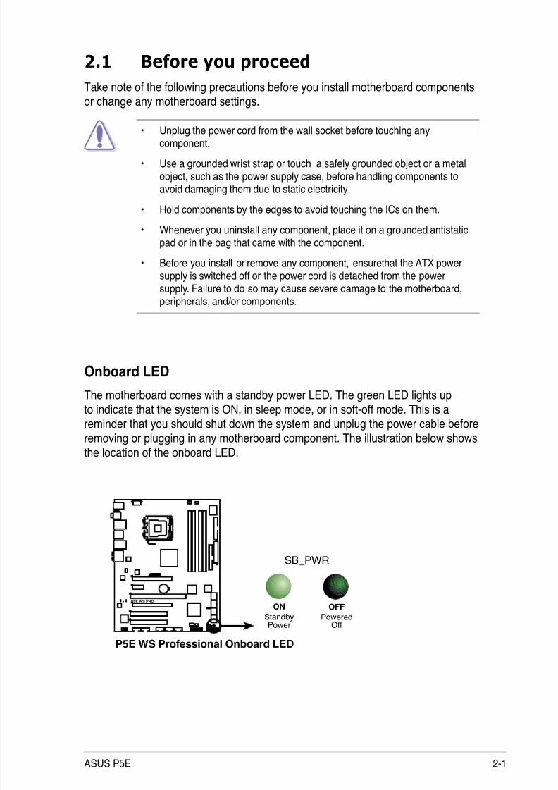
2.1 Before you proceed
Take note of the following precautions before you install motherboard components
or change any motherboard settings.
• Unplug the power cord from the wall socket before touching anycomponent.
• Use a grounded wrist strap or touch a safely grounded object or a metalobject, such as the power supply case, before handling components toavoid damaging them due to static electricity.
• Hold components by the edges to avoid touching the ICs on them.
• Whenever you uninstall any component, place it on a grounded antistaticpad or in the bag that came with the component.
• Before you install or remove any component, ensurethat the ATX powersupply is switched off or the power cord is detached from the powersupply. Failure to do so may cause severe damage to the motherboard,peripherals, and/or components.
P5E WS PRO
®
P5E WS Professional Onboard LED
SB_PWR
ON
StandbyPower
OFF
PoweredOff
Onboard LED
The motherboard comes with a standby power LED. The green LED lights upto indicate that the system is ON, in sleep mode, or in soft-off mode. This is areminder that you should shut down the system and unplug the power cable before
removing or plugging in any motherboard component. The illustration below shows
the location of the onboard LED.
8/13/2019 Asus P5E Motherboard User Guide
http://slidepdf.com/reader/full/asus-p5e-motherboard-user-guide 28/174
2-2 Chapter 2: Hardware information
P5E
®
2.2 Motherboard overview
Before you install the motherboard, study the conguration of your chassis toensure that the motherboard ts into it.
Make sure to unplug the power cord before installing or removing themotherboard. Failure to do so can cause you physical injury and damagemotherboard components.
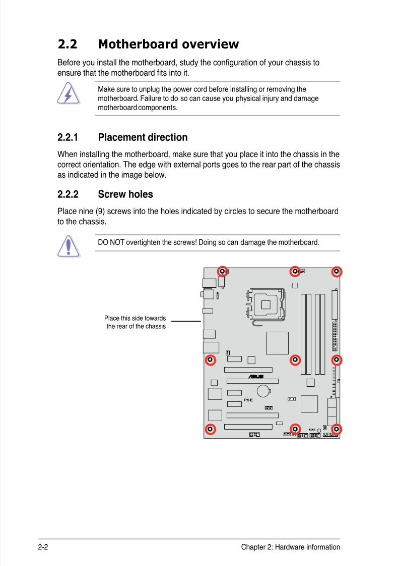
DO NOT overtighten the screws! Doing so can damage the motherboard.
2.2.1 Placement direction
When installing the motherboard, make sure that you place it into the chassis in the
correct orientation. The edge with external ports goes to the rear part of the chassisas indicated in the image below.
2.2.2 Screw holes
Place nine (9) screws into the holes indicated by circles to secure the motherboard
to the chassis.
Place this side towardsthe rear of the chassis
8/13/2019 Asus P5E Motherboard User Guide
http://slidepdf.com/reader/full/asus-p5e-motherboard-user-guide 29/174
ASUS P5E 2-3
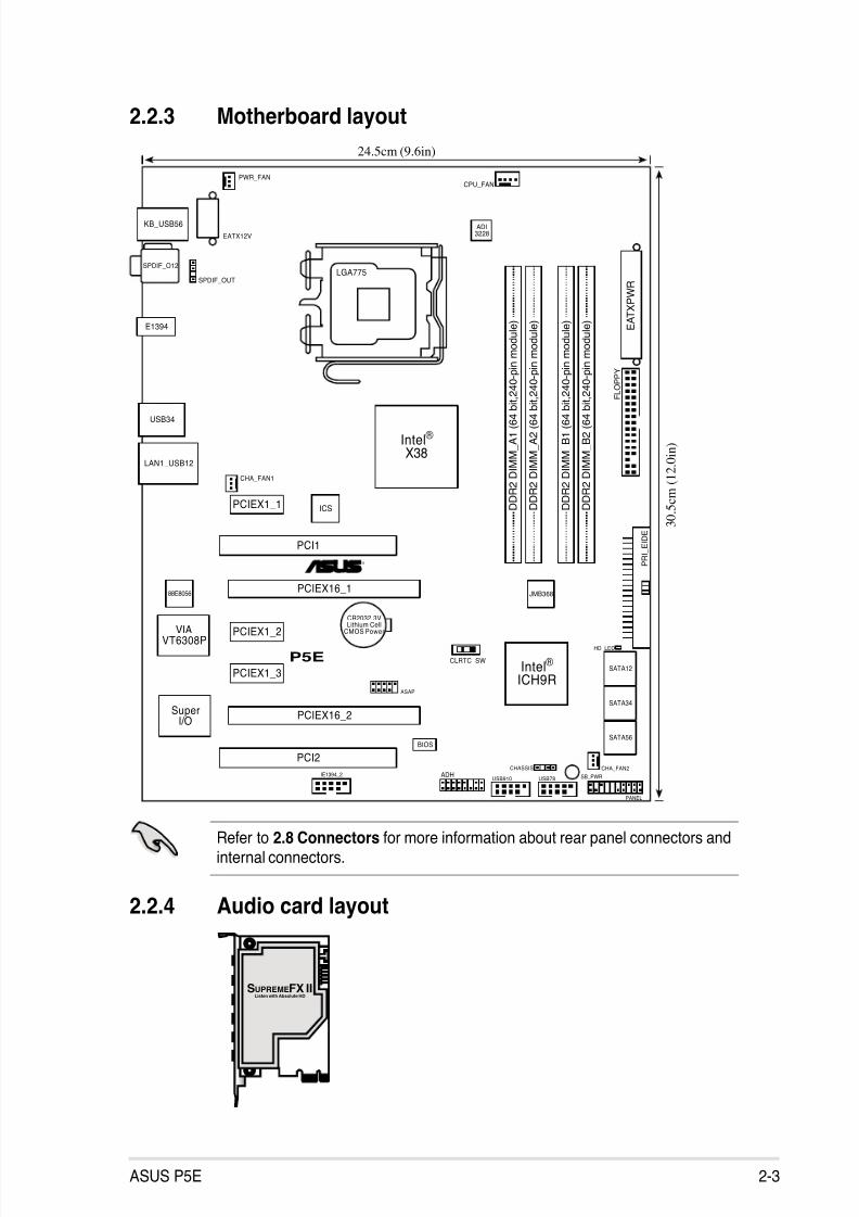
2.2.3 Motherboard layout
PANEL
P5E
®
CHASSIS
24.5cm (9.6in)
3 0 . 5 c m ( 1
2 . 0
i n )
CPU_FAN
D D R 2 D I M M_
A 1 ( 6 4 b i t , 2 4 0 - p i n m o d u l e )
F L O P P Y
SuperI/O
CLRTC_SW
Intel®
ICH9R
E A T X P W R
CR2032 3VLithium Cell
CMOS Power
Intel®
X38
KB_USB56
USB34
JMB368
CHA_FAN1
SPDIF_OUTLGA775
IE1394_2USB78
EATX12V
PWR_FAN
D D R 2 D I M M_
A 2 ( 6 4 b i t , 2 4 0 - p i n m o d u l e )
D D R 2 D I M M_
B 1 ( 6 4 b i t , 2 4 0 - p i n m o d u l e )
D D R 2 D I M M_
B 2 ( 6 4 b i t , 2 4 0 - p i n m o d u l e )
CHA_FAN2
BIOS
PCIEX1_2
PCIEX1_3
PCI1
PCIEX16_1
PCIEX16_2
PCI2
SATA56
SATA34
SATA12
LAN1_USB12
VIAVT6308P
ADHUSB910
P R I_ E I D E
SPDIF_O12
E1394
HD_LED
PCIEX1_1
88E8056
ASAP
SB_PWR
ADI3228
ICS
Refer to 2.8 Connectors for more information about rear panel connectors andinternal connectors.
2.2.4 Audio card layout
SUPREMEFX IIListen with Absolute HD
8/13/2019 Asus P5E Motherboard User Guide
http://slidepdf.com/reader/full/asus-p5e-motherboard-user-guide 30/174
2-4 Chapter 2: Hardware information
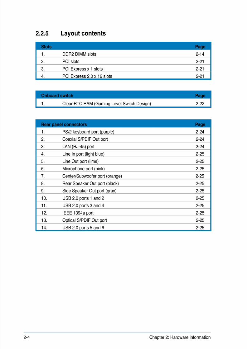
2.2.5 Layout contents
Slots Page
1. DDR2 DIMM slots 2-14
2. PCI slots 2-21
3. PCI Express x 1 slots 2-21
4. PCI Express 2.0 x 16 slots 2-21
Onboard switch Page
1. Clear RTC RAM (Gaming Level Switch Design) 2-22
Rear panel connectors Page
1. PS/2 keyboard port (purple) 2-24
2. Coaxial S/PDIF Out port 2-24
3. LAN (RJ-45) port 2-24
4. Line In port (light blue) 2-25
5. Line Out port (lime) 2-25
6. Microphone port (pink) 2-25
7. Center/Subwoofer port (orange) 2-25
8. Rear Speaker Out port (black) 2-25
9. Side Speaker Out port (gray) 2-25
10. USB 2.0 ports 1 and 2 2-25
11. USB 2.0 ports 3 and 4 2-25
12. IEEE 1394a port 2-25
13. Optical S/PDIF Out port 2-25
14. USB 2.0 ports 5 and 6 2-25

8/13/2019 Asus P5E Motherboard User Guide
http://slidepdf.com/reader/full/asus-p5e-motherboard-user-guide 31/174
ASUS P5E 2-5
Internal connectors Page
1. Floppy disk drive connector (34-1 pin FLOPPY) 2-26
2. IDE connector (40-1 pin PRI_EIDE) 2-27
3. ICH9R Serial ATA connectors (7-pin SATA1~6) 2-28
4. USB connectors (10-1 pin USB78, USB910, USB1112) 2-29
5. IEEE 1394a port connector (10-1 pin IE1394_2) 2-29
6. CPU, chassis, and optional fan connectors(4-pin CPU_FAN, 3-pin CHA_FAN1~2, 3-pin PWR_FAN)
2-30
7. Chassis intrusion connector (4-1 pin CHASSIS) 2-31
8. Digital audio connector (4-1 pin SPDIF_OUT for
ASUS HDMI VGA card) 2-31
9. ATX power connectors (24-pin EATXPWR, 8-pin EATX12V) 2-32
10. System panel connector (20-8 pin PANEL) 2-33
8/13/2019 Asus P5E Motherboard User Guide
http://slidepdf.com/reader/full/asus-p5e-motherboard-user-guide 32/174
2-6 Chapter 2: Hardware information
2.3 Central Processing Unit (CPU)
The motherboard comes with a surface mount LGA775 socket designed for the
Intel® Core™2 Quad / Core™2 Extreme / Core™2 Duo / Pentium® D / Pentium® 4 /
Pentium® Extreme processors.
• Upon purchase of the motherboard, make sure that the PnP cap is on
the socket and the socket contacts are not bent. Contact your retailerimmediately if the PnP cap is missing, or if you see any damage to the PnPcap/socket contacts/motherboard components. ASUS will shoulder the cost
of repair only if the damage is shipment/transit-related.
• Keep the cap after installing the motherboard. ASUS will process ReturnMerchandise Authorization (RMA) requests only if the motherboard comes
with the cap on the LGA775 socket.
• The product warranty does not cover damage to the socket contactsresulting from incorrect CPU installation/removal, or misplacement/loss/ incorrect removal of the PnP cap.
• Make sure that all power cables are unplugged before installing the CPU.
• If installing a dual-core CPU, connect the chassis fan cable to theCHA_FAN1 connector to ensure system stability.
8/13/2019 Asus P5E Motherboard User Guide
http://slidepdf.com/reader/full/asus-p5e-motherboard-user-guide 33/174
ASUS P5E 2-7
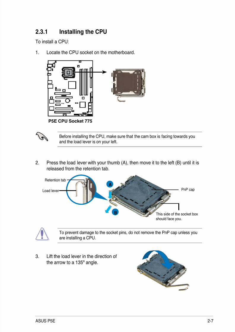
3. Lift the load lever in the direction of
the arrow to a 135º angle.
2. Press the load lever with your thumb (A), then move it to the left (B) until it isreleased from the retention tab.
Retention tab
Load lever
This side of the socket boxshould face you.
PnP cap
A
B
To prevent damage to the socket pins, do not remove the PnP cap unless youare installing a CPU.
2.3.1 Installing the CPU
To install a CPU:
1. Locate the CPU socket on the motherboard.
Before installing the CPU, make sure that the cam box is facing towards youand the load lever is on your left.
P5E
®
P5E CPU Socket 775
8/13/2019 Asus P5E Motherboard User Guide
http://slidepdf.com/reader/full/asus-p5e-motherboard-user-guide 34/174
2-8 Chapter 2: Hardware information
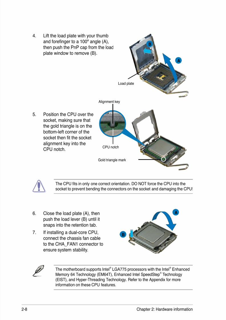
5. Position the CPU over the
socket, making sure thatthe gold triangle is on the
bottom-left corner of the
socket then t the socketalignment key into theCPU notch.
Alignment key
Gold triangle mark
6. Close the load plate (A), thenpush the load lever (B) until it
snaps into the retention tab.
7. If installing a dual-core CPU,
connect the chassis fan cable
to the CHA_FAN1 connector toensure system stability.
A
B
The CPU ts in only one correct orientation. DO NOT force the CPU into the
socket to prevent bending the connectors on the socket and damaging the CPU!
The motherboard supports Intel® LGA775 processors with the Intel® EnhancedMemory 64 Technology (EM64T), Enhanced Intel SpeedStep
® Technology
(EIST), and Hyper-Threading Technology. Refer to the Appendix for moreinformation on these CPU features.
4. Lift the load plate with your thumb
and forenger to a 100º angle (A),then push the PnP cap from the load
plate window to remove (B).
Load plate
A
B
CPU notch
8/13/2019 Asus P5E Motherboard User Guide
http://slidepdf.com/reader/full/asus-p5e-motherboard-user-guide 35/174
ASUS P5E 2-9
Fastener
Motherboard hole
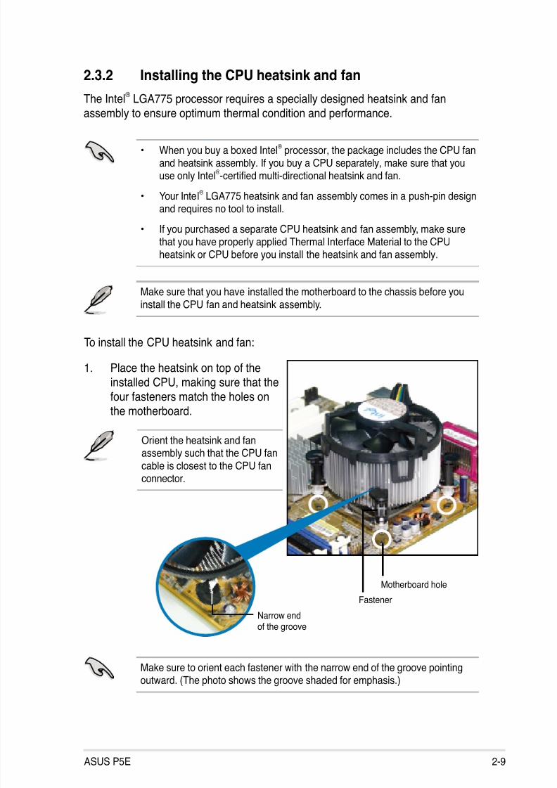
2.3.2 Installing the CPU heatsink and fan
The Intel® LGA775 processor requires a specially designed heatsink and fan
assembly to ensure optimum thermal condition and performance.
To install the CPU heatsink and fan:
1. Place the heatsink on top of the
installed CPU, making sure that the
four fasteners match the holes onthe motherboard.
• When you buy a boxed Intel® processor, the package includes the CPU fan
and heatsink assembly. If you buy a CPU separately, make sure that youuse only Intel
®-certied multi-directional heatsink and fan.
• Your Intel® LGA775 heatsink and fan assembly comes in a push-pin design
and requires no tool to install.
• If you purchased a separate CPU heatsink and fan assembly, make surethat you have properly applied Thermal Interface Material to the CPUheatsink or CPU before you install the heatsink and fan assembly.
Make sure that you have installed the motherboard to the chassis before youinstall the CPU fan and heatsink assembly.
Make sure to orient each fastener with the narrow end of the groove pointingoutward. (The photo shows the groove shaded for emphasis.)
Orient the heatsink and fanassembly such that the CPU fancable is closest to the CPU fanconnector.
Narrow endof the groove
8/13/2019 Asus P5E Motherboard User Guide
http://slidepdf.com/reader/full/asus-p5e-motherboard-user-guide 36/174
2-10 Chapter 2: Hardware information
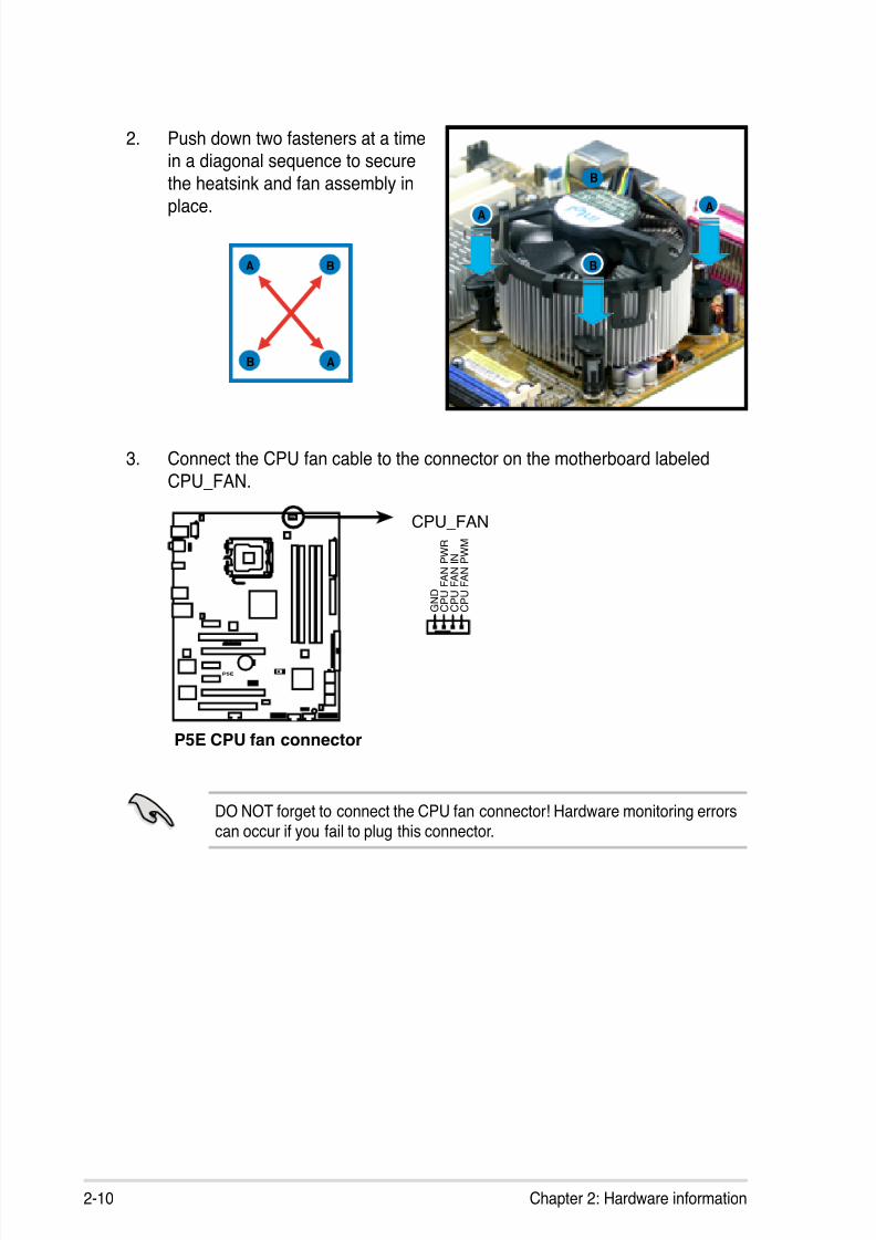
3. Connect the CPU fan cable to the connector on the motherboard labeled
CPU_FAN.
2. Push down two fasteners at a timein a diagonal sequence to secure
the heatsink and fan assembly in
place.
B
A
A
A B
B
DO NOT forget to connect the CPU fan connector! Hardware monitoring errors
can occur if you fail to plug this connector.
A
B
P5E
®
P5E CPU fan connector
CPU_FAN
GND
CPUFANPWR
CPUFANIN
CPUFANPWM
8/13/2019 Asus P5E Motherboard User Guide
http://slidepdf.com/reader/full/asus-p5e-motherboard-user-guide 37/174
ASUS P5E 2-11
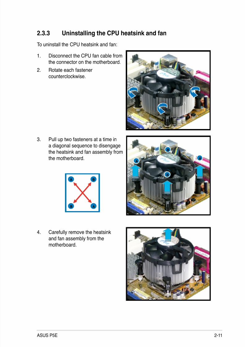
2.3.3 Uninstalling the CPU heatsink and fan
3. Pull up two fasteners at a time ina diagonal sequence to disengage
the heatsink and fan assembly from
the motherboard.
B
B
AA
A
A B
B
4. Carefully remove the heatsinkand fan assembly from themotherboard.
To uninstall the CPU heatsink and fan:
1. Disconnect the CPU fan cable fromthe connector on the motherboard.
2. Rotate each fastener
counterclockwise.
8/13/2019 Asus P5E Motherboard User Guide
http://slidepdf.com/reader/full/asus-p5e-motherboard-user-guide 38/174
2-12 Chapter 2: Hardware information
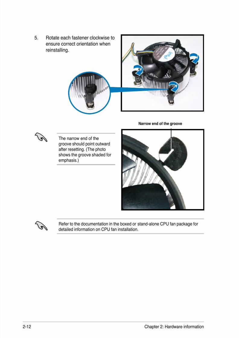
5. Rotate each fastener clockwise toensure correct orientation when
reinstalling.
Narrow end of the groove
Refer to the documentation in the boxed or stand-alone CPU fan package fordetailed information on CPU fan installation.
The narrow end of thegroove should point outwardafter resetting. (The photoshows the groove shaded foremphasis.)

8/13/2019 Asus P5E Motherboard User Guide
http://slidepdf.com/reader/full/asus-p5e-motherboard-user-guide 39/174
ASUS P5E 2-13
2.3.4 Installing the optional fans
Install the optional fan only if you are using a passive cooler or a water cooler.Installing the optional fan with an active CPU cooler will interfere with the airow
and destabilize the system.
1. Position the fan above the pipe
and heatsink assembly.
2. Fit the fan to the grooved edge of
the heatsink.
3. Carefully push down the fan until
it snugly ts the heatsink, thenconnect the fan cable.
4. The photo shows the fan installed
on the motherboard.
Optional fan on one side ns
• Plug the optional fan cables to any of the CHA_FAN1, CHA_FAN3, and
PWR_FAN connectors on the motherboard.
• Make sure the optional fan is installed correctly to prevent damage to the fan
and motherboard components.

8/13/2019 Asus P5E Motherboard User Guide
http://slidepdf.com/reader/full/asus-p5e-motherboard-user-guide 40/174
2-14 Chapter 2: Hardware information
Channel Sockets
Channel A DIMM_A1 and DIMM_A2
Channel B DIMM_B1 and DIMM_B2
2.4 System memory
2.4.1 Overview
The motherboard comes with four Double Data Rate 2 (DDR2) Dual Inline Memory
Modules (DIMM) sockets.The gure illustrates the location of the DDR2 DIMM sockets:
• *If you install a DDR2-1066 memory module, make sure that you set theDRAM Frequency item in BIOS to [DDR2-1066MHz]. See section 4.4Extreme Tweaker menu for details.
FSB DDR2
1333 1066*
1333 800
1333 667
1066 1066*
1066 800
1066 667
• This chipset ofcially supports DDR2-800 MHz. With the ASUS Super
Memspeed Technology, this motherboard natively supports up toDDR2-1066 MHz. See the table below.
P5E
®
P5E 240-pin DDR2 DIMM sockets
D I M M
_ A 2
D I M M
_ A 1
D I M M
_ B 2
D I M M
_ B 1
8/13/2019 Asus P5E Motherboard User Guide
http://slidepdf.com/reader/full/asus-p5e-motherboard-user-guide 41/174
ASUS P5E 2-15
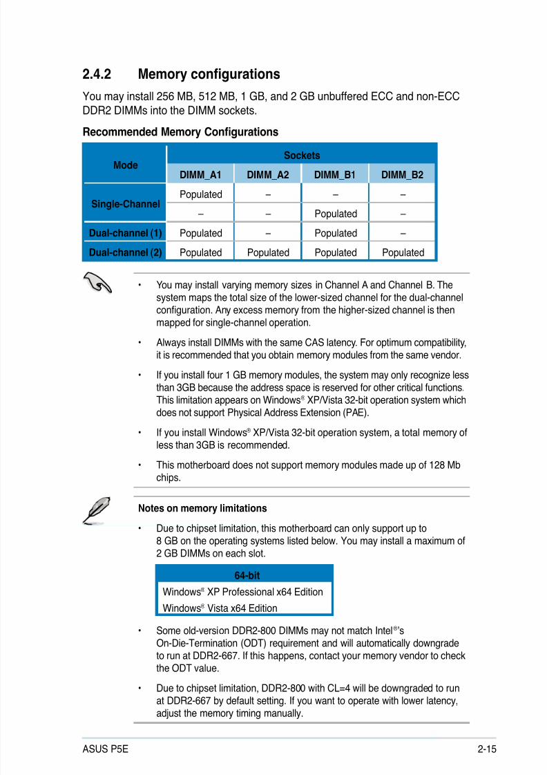
2.4.2 Memory congurations
You may install 256 MB, 512 MB, 1 GB, and 2 GB unbuffered ECC and non-ECC
DDR2 DIMMs into the DIMM sockets.
Recommended Memory Congurations
• You may install varying memory sizes in Channel A and Channel B. Thesystem maps the total size of the lower-sized channel for the dual-channelconguration. Any excess memory from the higher-sized channel is then
mapped for single-channel operation.
• Always install DIMMs with the same CAS latency. For optimum compatibility,it is recommended that you obtain memory modules from the same vendor.
• If you install four 1 GB memory modules, the system may only recognize less
than 3GB because the address space is reserved for other critical functions.This limitation appears on Windows® XP/Vista 32-bit operation system whichdoes not support Physical Address Extension (PAE).
• If you install Windows® XP/Vista 32-bit operation system, a total memory ofless than 3GB is recommended.
• This motherboard does not support memory modules made up of 128 Mbchips.
ModeSockets
DIMM_A1 DIMM_A2 DIMM_B1 DIMM_B2
Single-ChannelPopulated – – –
– – Populated –
Dual-channel (1) Populated – Populated –
Dual-channel (2) Populated Populated Populated Populated
64-bit
Windows® XP Professional x64 Edition
Windows® Vista x64 Edition
Notes on memory limitations
• Due to chipset limitation, this motherboard can only support up to8 GB on the operating systems listed below. You may install a maximum of2 GB DIMMs on each slot.
• Some old-version DDR2-800 DIMMs may not match Intel®’s
On-Die-Termination (ODT) requirement and will automatically downgradeto run at DDR2-667. If this happens, contact your memory vendor to checkthe ODT value.
• Due to chipset limitation, DDR2-800 with CL=4 will be downgraded to runat DDR2-667 by default setting. If you want to operate with lower latency,adjust the memory timing manually.
8/13/2019 Asus P5E Motherboard User Guide
http://slidepdf.com/reader/full/asus-p5e-motherboard-user-guide 42/174
2-16 Chapter 2: Hardware information
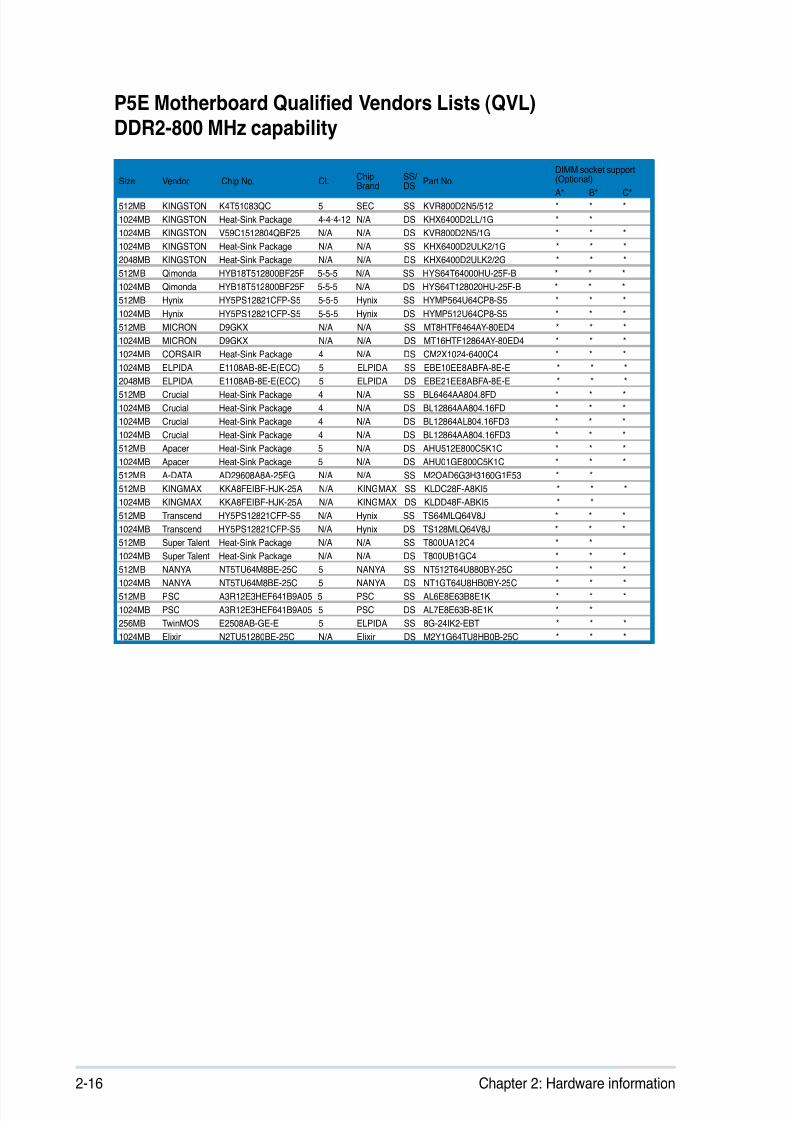
P5E Motherboard Qualied Vendors Lists (QVL) DDR2-800 MHz capability
Size Vendor Chip No. CLChip
Brand
SS/
DSPart No.
DIMM socket support(Optional)
A* B* C*
512MB KINGSTON K4T51083QC 5 SEC SS KVR800D2N5/512 * * *
1024MB KINGSTON Heat-Sink Package 4-4-4-12 N/A DS KHX6400D2LL/1G * *
1024MB KINGSTON V59C1512804QBF25 N/A N/A DS KVR800D2N5/1G * * *
1024MB KINGSTON Heat-Sink Package N/A N/A SS KHX6400D2ULK2/1G * * *
2048MB KINGSTON Heat-Sink Package N/A N/A DS KHX6400D2ULK2/2G * * *
512MB Qimonda HYB18T512800BF25F 5-5-5 N/A SS HYS64T64000HU-25F-B * * *
1024MB Qimonda HYB18T512800BF25F 5-5-5 N/A DS HYS64T128020HU-25F-B * * *
512MB Hynix HY5PS12821CFP-S5 5-5-5 Hynix SS HYMP564U64CP8-S5 * * *
1024MB Hynix HY5PS12821CFP-S5 5-5-5 Hynix DS HYMP512U64CP8-S5 * * *
512MB MICRON D9GKX N/A N/A SS MT8HTF6464AY-80ED4 * * *
1024MB MICRON D9GKX N/A N/A DS MT16HTF12864AY-80ED4 * * *
1024MB CORSAIR Heat-Sink Package 4 N/A DS CM2X1024-6400C4 * * *
1024MB ELPIDA E1108AB-8E-E(ECC) 5 ELPIDA SS EBE10EE8ABFA-8E-E * * *
2048MB ELPIDA E1108AB-8E-E(ECC) 5 ELPIDA DS EBE21EE8ABFA-8E-E * * *
512MB Crucial Heat-Sink Package 4 N/A SS BL6464AA804.8FD * * *
1024MB Crucial Heat-Sink Package 4 N/A DS BL12864AA804.16FD * * *
1024MB Crucial Heat-Sink Package 4 N/A DS BL12864AL804.16FD3 * * *
1024MB Crucial Heat-Sink Package 4 N/A DS BL12864AA804.16FD3 * * *
512MB Apacer Heat-Sink Package 5 N/A DS AHU512E800C5K1C * * *
1024MB Apacer Heat-Sink Package 5 N/A DS AHU01GE800C5K1C * * *
512MB A-DATA AD29608A8A-25EG N/A N/A SS M2OAD6G3H3160G1E53 * *
512MB KINGMAX KKA8FEIBF-HJK-25A N/A KINGMAX SS KLDC28F-A8KI5 * * *
1024MB KINGMAX KKA8FEIBF-HJK-25A N/A KINGMAX DS KLDD48F-ABKI5 * *
512MB Transcend HY5PS12821CFP-S5 N/A Hynix SS TS64MLQ64V8J * * *
1024MB Transcend HY5PS12821CFP-S5 N/A Hynix DS TS128MLQ64V8J * * *
512MB Super Talent Heat-Sink Package N/A N/A SS T800UA12C4 * *
1024MB Super Talent Heat-Sink Package N/A N/A DS T800UB1GC4 * * *512MB NANYA NT5TU64M8BE-25C 5 NANYA SS NT512T64U880BY-25C * * *
1024MB NANYA NT5TU64M8BE-25C 5 NANYA DS NT1GT64U8HB0BY-25C * * *
512MB PSC A3R12E3HEF641B9A05 5 PSC SS AL6E8E63B8E1K * * *
1024MB PSC A3R12E3HEF641B9A05 5 PSC DS AL7E8E63B-8E1K * *
256MB TwinMOS E2508AB-GE-E 5 ELPIDA SS 8G-24IK2-EBT * * *
1024MB Elixir N2TU51280BE-25C N/A Elixir DS M2Y1G64TU8HB0B-25C * * *
8/13/2019 Asus P5E Motherboard User Guide
http://slidepdf.com/reader/full/asus-p5e-motherboard-user-guide 43/174
ASUS P5E 2-17
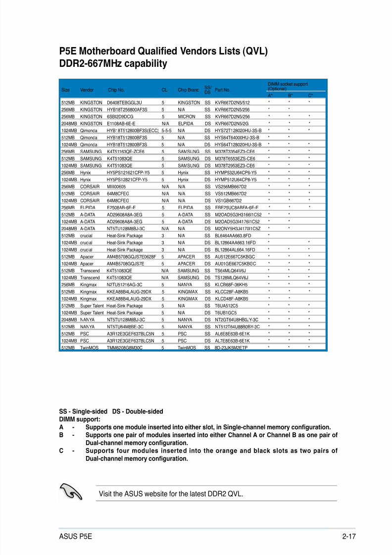
Visit the ASUS website for the latest DDR2 QVL.
P5E Motherboard Qualied Vendors Lists (QVL) DDR2-667MHz capability
SS - Single-sided DS - Double-sidedDIMM support:A - Supports one module inserted into either slot, in Single-channel memory conguration.B - Supports one pair of modules inserted into either Channel A or Channel B as one pair of
Dual-channel memory conguration.C - Supports four modules inserted into the orange and black slots as two pairs of
Dual-channel memory conguration.
Size Vendor Chip No. CL Chip BrandSS/
DSPart No.
DIMM socket support(Optional)
A* B* C*
512MB KINGSTON D6408TEBGGL3U 5 KINGSTON SS KVR667D2N5/512 * * *
256MB KINGSTON HYB18T256800AF3S 5 N/A SS KVR667D2N5/256 * *
256MB KINGSTON 6SBI2D9DCG 5 MICRON SS KVR667D2N5/256 * * *
2048MB KINGSTON E1108AB-6E-E N/A ELPIDA DS KVR667D2N5/2G * * *
1024MB Qimonda HYB18T512800BF3S(ECC) 5-5-5 N/A DS HYS72T128020HU-3S-B * * *
512MB Qimonda HYB18T512800BF3S 5 N/A SS HYS64T64000HU-3S-B * *
1024MB Qimonda HYB18T512800BF3S 5 N/A DS HYS64T128020HU-3S-B * * *
256MB SAMSUNG K4T51163QE-ZCE6 5 SAMSUNG SS M378T3354EZ3-CE6 * * *
512MB SAMSUNG K4T51083QE 5 SAMSUNG DS M378T6553EZS-CE6 * * *
1024MB SAMSUNG K4T51083QE 5 SAMSUNG DS M378T2953EZ3-CE6 * * *
256MB Hynix HY5PS121621CFP-Y5 5 Hynix SS HYMP532U64CP6-Y5 * * *
1024MB Hynix HY5PS12821CFP-Y5 5 Hynix DS HYMP512U64CP8-Y5 * * *
256MB CORSAIR MIII00605 N/A N/A SS VS256MB667D2 * * *
512MB CORSAIR 64M8CFEG N/A N/A SS VS512MB667D2 * * *
1024MB CORSAIR 64M8CFEG N/A N/A DS VS1GB667D2 * * *
256MB ELPIDA E2508AB-6E-E 5 ELPIDA SS EBE25UC8ABFA-6E-E * * *
512MB A-DATA AD29608A8A-3EG 5 A-DATA SS M2OAD5G3H3166I1C52 * *
1024MB A-DATA AD29608A8A-3EG 5 A-DATA DS M2OAD5G3I4176I1C52 * *
2048MB A-DATA NT5TU128M8BJ-3C N/A N/A DS M2ONY5H3J4170I1C5Z * *
512MB crucial Heat-Sink Package 3 N/A SS BL6464AA663.8FD *
1024MB crucial Heat-Sink Package 3 N/A DS BL12864AA663.16FD * *
1024MB crucial Heat-Sink Package 3 N/A DS BL12864AL664.16FD * * *
512MB Apacer AM4B5708GQJS7E0628F 5 APACER SS AU512E667C5KBGC * * *
1024MB Apacer AM4B5708GQJS7E 5 APACER DS AU01GE667C5KBGC * * *
512MB Transcend K4T51083QE N/A SAMSUNG SS TS64MLQ64V6J * * *
1024MB Transcend K4T51083QE N/A SAMSUNG DS TS128MLQ64V6J * * *256MB Kingmax N2TU51216AG-3C 5 NANYA SS KLCB68F-36KH5 * * *
512MB Kingmax KKEA88B4LAUG-29DX 5 KINGMAX SS KLCC28F-A8KB5 * * *
1024MB Kingmax KKEA88B4LAUG-29DX 5 KINGMAX DS KLCD48F-A8KB5 * *
512MB Super Talent Heat-Sink Package 5 N/A SS T6UA512C5 * * *
1024MB Super Talent Heat-Sink Package 5 N/A DS T6UB1GC5 * * *
2048MB NANYA NT5TU128M8BJ-3C 5 NANYA DS NT2GT64U8HB0JY-3C * * *
512MB NANYA NT5TU64M8BE-3C 5 NANYA SS NT512T64U88B0BY-3C * * *
512MB PSC A3R12E3GEF637BLC5N 5 PSC SS AL6E8E63B-6E1K * * *
1024MB PSC A3R12E3GEF637BLC5N 5 PSC DS AL7E8E63B-6E1K * * *
512MB TwinMOS TMM6208G8M30C 5 TwinMOS SS 8D-23JK5M2ETP * * *
8/13/2019 Asus P5E Motherboard User Guide
http://slidepdf.com/reader/full/asus-p5e-motherboard-user-guide 44/174
2-18 Chapter 2: Hardware information
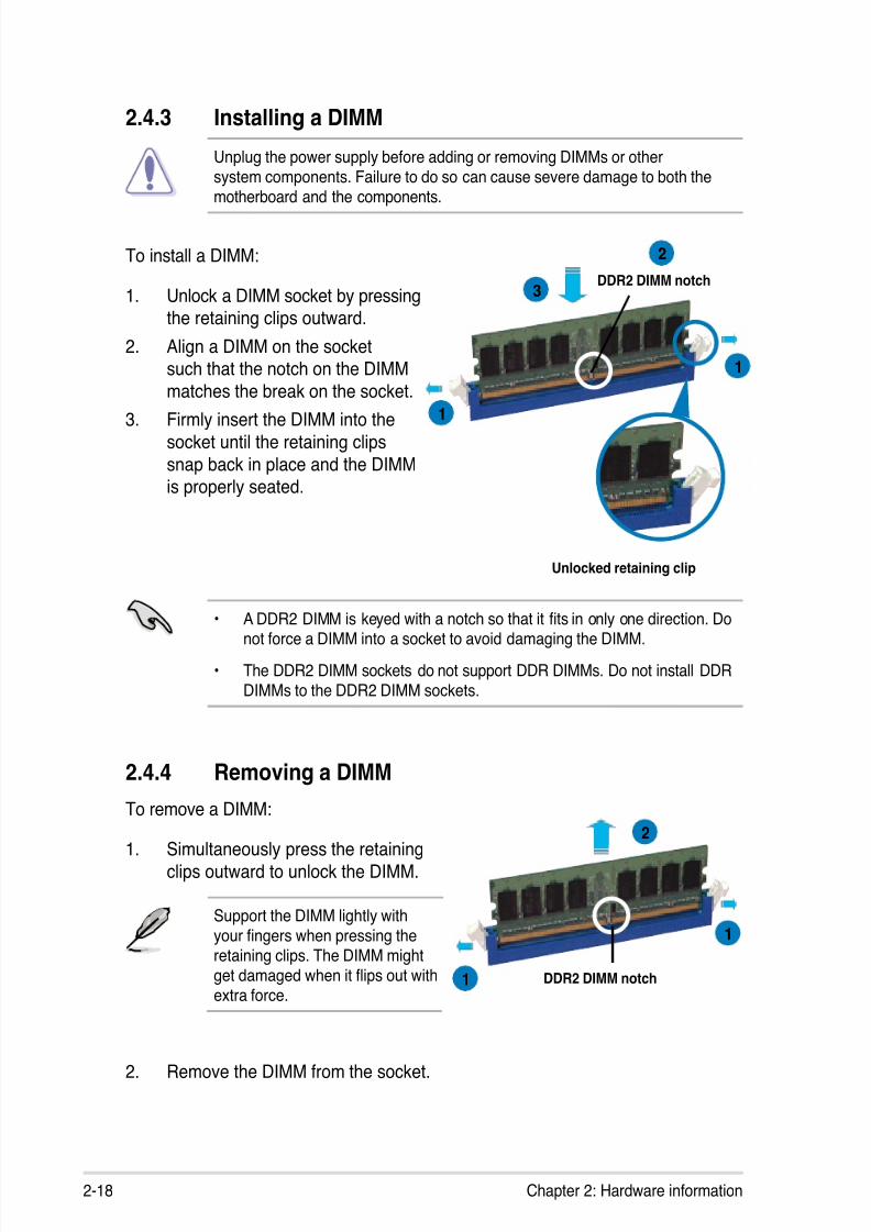
2.4.3 Installing a DIMM
Unplug the power supply before adding or removing DIMMs or othersystem components. Failure to do so can cause severe damage to both the
motherboard and the components.
To install a DIMM:
1. Unlock a DIMM socket by pressingthe retaining clips outward.
2. Align a DIMM on the socketsuch that the notch on the DIMM
matches the break on the socket.
3. Firmly insert the DIMM into the
socket until the retaining clips
snap back in place and the DIMMis properly seated.
2.4.4 Removing a DIMM
To remove a DIMM:
1. Simultaneously press the retaining
clips outward to unlock the DIMM.
2. Remove the DIMM from the socket.
Support the DIMM lightly withyour ngers when pressing the
retaining clips. The DIMM mightget damaged when it ips out with
extra force.
Unlocked retaining clip
DDR2 DIMM notch
1
2
3
1
• A DDR2 DIMM is keyed with a notch so that it ts in only one direction. Donot force a DIMM into a socket to avoid damaging the DIMM.
• The DDR2 DIMM sockets do not support DDR DIMMs. Do not install DDRDIMMs to the DDR2 DIMM sockets.
DDR2 DIMM notch1
2
1
8/13/2019 Asus P5E Motherboard User Guide
http://slidepdf.com/reader/full/asus-p5e-motherboard-user-guide 45/174
ASUS P5E 2-19
2.5 Expansion slots
In the future, you may need to install expansion cards. The following sub-sections
describe the slots and the expansion cards that they support.
2.5.1 Installing an expansion card
To install an expansion card:
1. Before installing the expansion card, read the documentation that came with
it and make the necessary hardware settings for the card.2. Remove the system unit cover (if your motherboard is already installed in a
chassis).
3. Remove the bracket opposite the slot that you intend to use. Keep the screw
for later use.
4. Align the card connector with the slot and press rmly until the card iscompletely seated on the slot.
5. Secure the card to the chassis with the screw you removed earlier.
6. Replace the system cover.
2.5.2 Conguring an expansion card
After installing the expansion card, congure it by adjusting the software settings.
1. Turn on the system and change the necessary BIOS settings, if any. SeeChapter 4 for information on BIOS setup.
2. Assign an IRQ to the card. Refer to the tables on the next page.
3. Install the software drivers for the expansion card.
Make sure to unplug the power cord before adding or removing expansioncards. Failure to do so may cause you physical injury and damage motherboardcomponents.
When using PCI cards on shared slots, ensure that the drivers support “ShareIRQ” or that the cards do not need IRQ assignments. Otherwise, conicts will
arise between the two PCI groups, making the system unstable and the cardinoperable. Refer to the table on the next page for details.
8/13/2019 Asus P5E Motherboard User Guide
http://slidepdf.com/reader/full/asus-p5e-motherboard-user-guide 46/174
2-20 Chapter 2: Hardware information
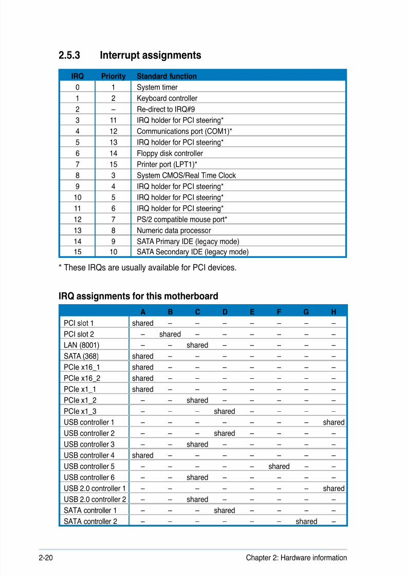
2.5.3 Interrupt assignments
IRQ assignments for this motherboard
A B C D E F G H
PCI slot 1 shared – – – – – – –
PCI slot 2 – shared – – – – – –
LAN (8001) – – shared – – – – –
SATA (368) shared – – – – – – –
PCIe x16_1 shared – – – – – – –
PCIe x16_2 shared – – – – – – –
PCIe x1_1 shared – – – – – – –
PCIe x1_2 – – shared – – – – –
PCIe x1_3 – – – shared – – – –
USB controller 1 – – – – – – – shared
USB controller 2 – – – shared – – – –
USB controller 3 – – shared – – – – –
USB controller 4 shared – – – – – – –
USB controller 5 – – – – – shared – –
USB controller 6 – – shared – – – – –USB 2.0 controller 1 – – – – – – – shared
USB 2.0 controller 2 – – shared – – – – –
SATA controller 1 – – – shared – – – –
SATA controller 2 – – – – – – shared –
IRQ Priority Standard function
0 1 System timer
1 2 Keyboard controller
2 – Re-direct to IRQ#9
3 11 IRQ holder for PCI steering*
4 12 Communications port (COM1)*
5 13 IRQ holder for PCI steering*
6 14 Floppy disk controller
7 15 Printer port (LPT1)*
8 3 System CMOS/Real Time Clock
9 4 IRQ holder for PCI steering*
10 5 IRQ holder for PCI steering*
11 6 IRQ holder for PCI steering*
12 7 PS/2 compatible mouse port*
13 8 Numeric data processor
14 9 SATA Primary IDE (legacy mode)
15 10 SATA Secondary IDE (legacy mode)
* These IRQs are usually available for PCI devices.
8/13/2019 Asus P5E Motherboard User Guide
http://slidepdf.com/reader/full/asus-p5e-motherboard-user-guide 47/174
ASUS P5E 2-21
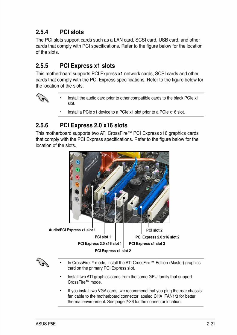
2.5.4 PCI slotsThe PCI slots support cards such as a LAN card, SCSI card, USB card, and other
cards that comply with PCI specications. Refer to the gure below for the locationof the slots.
2.5.5 PCI Express x1 slotsThis motherboard supports PCI Express x1 network cards, SCSI cards and other
cards that comply with the PCI Express specications. Refer to the gure below forthe location of the slots.
• Install the audio card prior to other compatible cards to the black PCIe x1slot.
• Install a PCIe x1 device to a PCIe x1 slot prior to a PCIe x16 slot.
2.5.6 PCI Express 2.0 x16 slotsThis motherboard supports two ATI CrossFire™ PCI Express x16 graphics cards
that comply with the PCI Express specications. Refer to the gure below for thelocation of the slots.
• In CrossFire™ mode, install the ATI CrossFire™ Edition (Master) graphicscard on the primary PCI Express slot.
• Install two ATI graphics cards from the same GPU family that supportCrossFire™ mode.
• If you install two VGA cards, we recommend that you plug the rear chassisfan cable to the motherboard connector labeled CHA_FAN1/3 for betterthermal environment. See page 2-36 for the connector location.
PCI slot 1
PCI Express 2.0 x16 slot 1 PCI Express x1 slot 3
PCI Express 2.0 x16 slot 2
PCI slot 2
PCI Express x1 slot 2
Audio/PCI Express x1 slot 1

8/13/2019 Asus P5E Motherboard User Guide
http://slidepdf.com/reader/full/asus-p5e-motherboard-user-guide 48/174
2-22 Chapter 2: Hardware information
2.6 Switch
1. Clear RTC RAM (Gaming Level Switch Design)
This switch allows you to clear the Real Time Clock (RTC) RAM inCMOS. You can clear the CMOS memory of date, time, and system setup
parameters by erasing the CMOS RTC RAM data. The onboard button
cell battery powers the RAM data in CMOS, which include system setup
information such as system passwords.
To erase the RTC RAM:
1. Turn OFF the computer and unplug the power cord.
2. Remove the onboard battery.
3. Move the switch from Disable (default) to Enable. Keep the switch on
Enable for about 5~10 seconds, then move the switch back to Disable.
4. Reinstall the battery.
5. Plug the power cord and turn ON the computer.
6. Hold down the <Del> key during the boot process and enter BIOS setupto re-enter data.
P5E
®
P5E Clear RTC RAM
CLRTC_SW
DisableEnable(Default)
• You do not need to clear the RTC when the system hangs due tooverclocking. For system failure due to overclocking, use the C.P.R. (CPUParameter Recall) feature. Shut down and reboot the system so the BIOScan automatically reset parameter settings to default values.
• Due to the chipset limitation, AC power off is required prior using C.P.R.
function. You must turn off and on the power supply or unplug and plug thepower cord before reboot the system.
Except when clearing the RTC RAM, never move the CLRTC switch from itsdefault position, or the system will encounter boot failure!
8/13/2019 Asus P5E Motherboard User Guide
http://slidepdf.com/reader/full/asus-p5e-motherboard-user-guide 49/174
ASUS P5E 2-23
2.7 Audio card installation
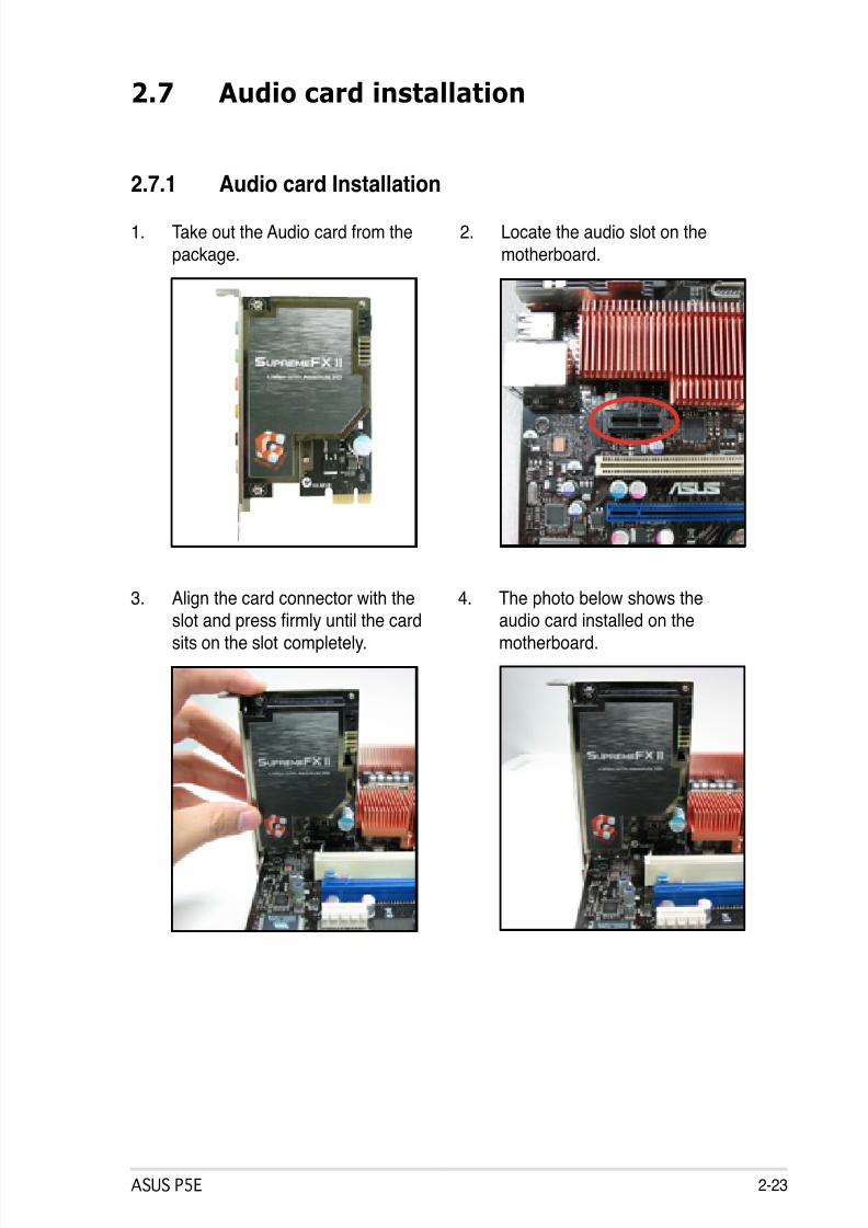
2.7.1 Audio card Installation
1. Take out the Audio card from the
package.
2. Locate the audio slot on the
motherboard.
3. Align the card connector with the
slot and press rmly until the cardsits on the slot completely.
4. The photo below shows the
audio card installed on themotherboard.
8/13/2019 Asus P5E Motherboard User Guide
http://slidepdf.com/reader/full/asus-p5e-motherboard-user-guide 50/174
2-24 Chapter 2: Hardware information
2.8 Connectors
2.8.1 Rear panel connectors
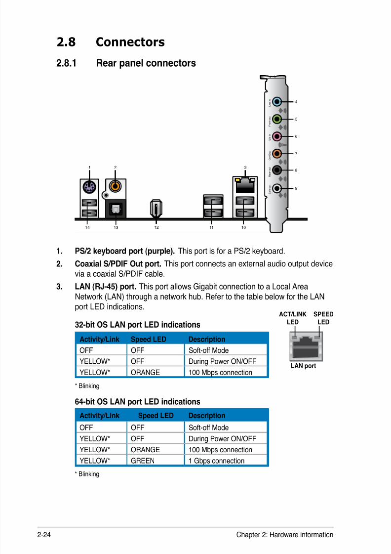
1. PS/2 keyboard port (purple). This port is for a PS/2 keyboard.
2. Coaxial S/PDIF Out port. This port connects an external audio output device
via a coaxial S/PDIF cable.3. LAN (RJ-45) port. This port allows Gigabit connection to a Local Area
Network (LAN) through a network hub. Refer to the table below for the LANport LED indications.
21
1314
3
4
12
L i n e i n
M i c i n
C e n / S u b
R e a r - o u t
S i d e - o u t
F r o n t - o u t
5
6
7
8
9
11 10
32-bit OS LAN port LED indications
* Blinking
Activity/Link Speed LED Description
OFF OFF Soft-off Mode
YELLOW* OFF During Power ON/OFF
YELLOW* ORANGE 100 Mbps connection
64-bit OS LAN port LED indications
Activity/Link Speed LED Description
OFF OFF Soft-off Mode
YELLOW* OFF During Power ON/OFF
YELLOW* ORANGE 100 Mbps connection
YELLOW* GREEN 1 Gbps connection* Blinking
SPEEDLED
ACT/LINKLED
LAN port
8/13/2019 Asus P5E Motherboard User Guide
http://slidepdf.com/reader/full/asus-p5e-motherboard-user-guide 51/174
ASUS P5E 2-25
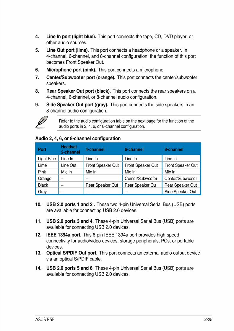
4. Line In port (light blue). This port connects the tape, CD, DVD player, orother audio sources.
5. Line Out port (lime). This port connects a headphone or a speaker. In
4-channel, 6-channel, and 8-channel conguration, the function of this portbecomes Front Speaker Out.
6. Microphone port (pink). This port connects a microphone.
7. Center/Subwoofer port (orange). This port connects the center/subwoofer
speakers.
8. Rear Speaker Out port (black). This port connects the rear speakers on a
4-channel, 6-channel, or 8-channel audio conguration.
9. Side Speaker Out port (gray). This port connects the side speakers in an
8-channel audio conguration.
Refer to the audio conguration table on the next page for the function of theaudio ports in 2, 4, 6, or 8-channel conguration.
Audio 2, 4, 6, or 8-channel conguration
PortHeadset2-channel
4-channel 6-channel 8-channel
Light Blue Line In Line In Line In Line In
Lime Line Out Front Speaker Out Front Speaker Out Front Speaker OutPink Mic In Mic In Mic In Mic In
Orange – – Center/Subwoofer Center/Subwoofer
Black – Rear Speaker Out Rear Speaker Ou Rear Speaker Out
Gray – – – Side Speaker Out
10. USB 2.0 ports 1 and 2 . These two 4-pin Universal Serial Bus (USB) portsare available for connecting USB 2.0 devices.
11. USB 2.0 ports 3 and 4. These 4-pin Universal Serial Bus (USB) ports areavailable for connecting USB 2.0 devices.
12. IEEE 1394a port. This 6-pin IEEE 1394a port provides high-speedconnectivity for audio/video devices, storage peripherals, PCs, or portable
devices.
13. Optical S/PDIF Out port. This port connects an external audio output device
via an optical S/PDIF cable.
14. USB 2.0 ports 5 and 6. These 4-pin Universal Serial Bus (USB) ports are
available for connecting USB 2.0 devices.

8/13/2019 Asus P5E Motherboard User Guide
http://slidepdf.com/reader/full/asus-p5e-motherboard-user-guide 52/174
2-26 Chapter 2: Hardware information
2.8.2 Internal connectors
1. Floppy disk drive connector (34-1 pin FLOPPY)
This connector is for the provided oppy disk drive (FDD) signal cable. Insert
one end of the cable to this connector, then connect the other end to thesignal connector at the back of the oppy disk drive.
Pin 5 on the connector is removed to prevent incorrect cable connection whenusing a FDD cable with a covered Pin 5.
P5E
®
P5E Floppy disk drive connector
NOTE: Orient the red markings onthe floppy ribbon cable to PIN 1.
PIN 1
FLOPPY

8/13/2019 Asus P5E Motherboard User Guide
http://slidepdf.com/reader/full/asus-p5e-motherboard-user-guide 53/174
ASUS P5E 2-27
P5E
®
P5E IDE connector
NOTE: Orient the red markings(usually zigzag) on the IDEcable to PIN 1.
PRI_EIDE
2. IDE connector (40-1 pin PRI_EIDE)
The onboard IDE connector is for the Ultra DMA 133/100 signal cable. Thereare three connectors on each Ultra DMA 133/100 signal cable: blue, black,
and gray. Connect the blue connector to the motherboard’s IDE connector,
then select one of the following modes to congure your device.
• Pin 20 on the IDE connector is removed to match the covered hole on theUltra DMA cable connector. This prevents incorrect insertion when youconnect the IDE cable.
• Use the 80-conductor IDE cable for Ultra DMA 133/100 IDE devices.
If any device jumper is set as “Cable-Select,” make sure all other device jumpers have the same setting.
Drive jumper settingMode of
device(s)Cable connector
Single device Cable-Select or Master - Black
Two devices
Cable-Select Master BlackSlave Gray
Master MasterBlack or gray
Slave Slave

8/13/2019 Asus P5E Motherboard User Guide
http://slidepdf.com/reader/full/asus-p5e-motherboard-user-guide 54/174
2-28 Chapter 2: Hardware information
3. ICH9R Serial ATA connectors (7-pin SATA1~6)
These connectors are for the Serial ATA signal cables for Serial ATA hard diskdrives.
If you installed Serial ATA hard disk drives, you can create a RAID 0, RAID1, RAID 5, RAID 10 conguration with the Intel® Matrix Storage Technology
through the onboard Intel® ICH9R RAID controller.
• You must install the Windows® XP Service Pack 1 before using SerialATA hard disk drives. The Serial ATA RAID feature (RAID 0/RAID 1/RAID5/RAID 10) is available only if you are using Windows® XP or later version.
• These connectors are set to Standard IDE mode by default. In StandardIDE mode, you can connect Serial ATA boot/data hard disk drives to theseconnectors. If you intend to create a Serial ATA RAID set using theseconnectors, set the [Congure SATA as] item in the BIOS to [RAID]. See
section 4.3.6 SATA Conguration for details.
• For RAID 5, use at least three hard disk drives. For RAID 10, use at least
four hard disk drives. Use two to four Serial ATA hard disk drives for eachRAID 0 or RAID 1 set.
• Before creating a RAID set, refer to 5.4.3 Intel® RAID congurations or
the manual bundled in the motherboard support DVD.
P5E
®
P5E SATA connectors
GNDRSATA_TXP1RSATA_TXN1
GNDRSATA_RXP1RSATA_RXN1
GND
SATA1 GNDRSATA_TXP2RSATA_TXN2
GNDRSATA_RXP2RSATA_RXN2
GND
SATA2
GNDRSATA_TXP3RSATA_TXN3
GNDRSATA_RXP3RSATA_RXN3
GND
SATA3 GNDRSATA_TXP4RSATA_TXN4
GNDRSATA_RXP4RSATA_RXN4
GND
SATA4
GNDRSATA_TXP5RSATA_TXN5
GNDRSATA_RXP5RSATA_RXN5
GND
SATA5 GNDRSATA_TXP6RSATA_TXN6
GNDRSATA_RXP6RSATA_RXN6
GND
SATA6
Connect the right-angle sideof SATA signal cable to SATAdevice. Or you may connect theright-angle side of SATA cable tothe onboard SATA port to avoid
mechanical conict with hugegraphics cards.
right angle side

8/13/2019 Asus P5E Motherboard User Guide
http://slidepdf.com/reader/full/asus-p5e-motherboard-user-guide 55/174
ASUS P5E 2-29
4. USB connectors (10-1 pin USB 78, USB 910, USB 1112)
These connectors are for USB 2.0 ports. Connect the USB module cableto any of these connectors, then install the module to a slot opening at the
back of the system chassis. These USB connectors comply with USB 2.0
specication that supports up to 480 Mbps connection speed.
Never connect a 1394 cable to the USB connectors. Doing so will damage themotherboard!
You can connect the USB cable to ASUS Q-Connector (USB, blue) rst, and
then install the Q-Connector (USB) to the USB connector onboard.
P5E
®
P5EUSB 2.0 connectors
U S B
+ 5 V
U S B
_ P 1 0 -
U S B
_ P 1 0 +
G N D
N C
U S B + 5 V
U S B_
P 9 -
U S B_
P 9 +
G N D
USB910
U S B
+ 5 V
U S B
_ P 8 -
U S B
_ P 8 +
G N D
N C
U S B + 5 V
U S B_
P 7 -
U S B_
P 7 +
G N D
USB78
5. IEEE 1394a port connector (10-1 pin IE1394_2)
This connector is for a IEEE 1394a port. Connect the IEEE 1394a modulecable to this connector, then install the module to a slot opening at the back
of the system chassis.
Never connect a USB cable to the IEEE 1394a connector. Doing so will damagethe motherboard!
You can connect the 1394 cable to ASUS Q-Connector (1394, red) rst, and
then install the Q-Connector (1394) to the 1394 connector onboard.
P5E
®
P5E IEEE 1394a connector
IE1394_2PIN 1
GND
+1 2 V
T P B 1 -
GND
T P A 1 -
+1 2 V
T P B 1 +
GND
T P A 1 +
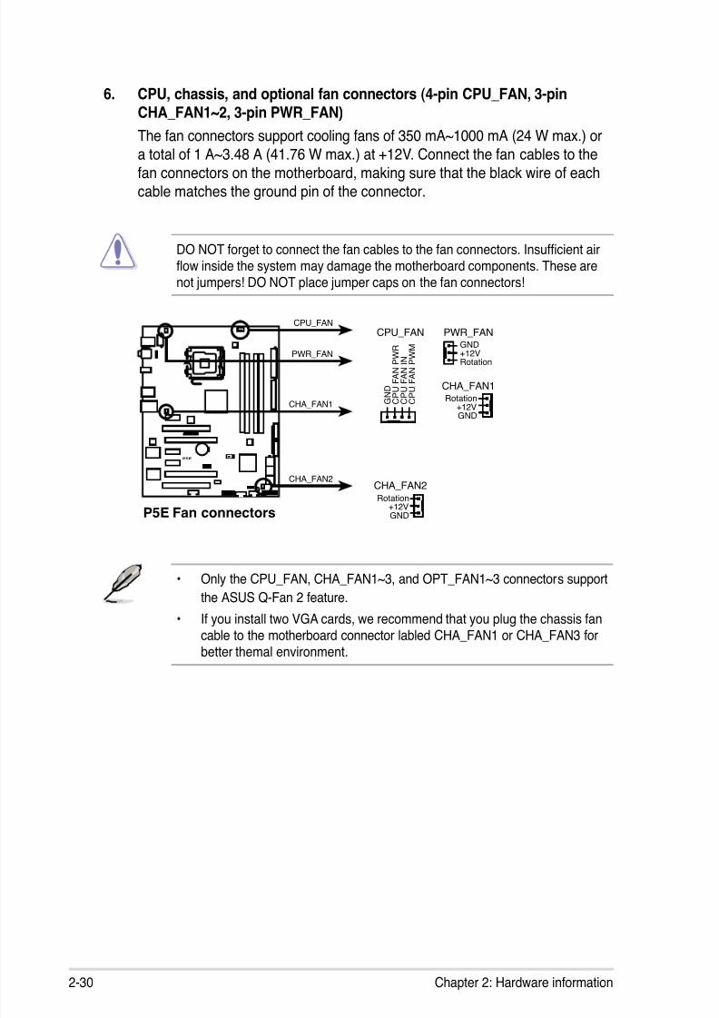
8/13/2019 Asus P5E Motherboard User Guide
http://slidepdf.com/reader/full/asus-p5e-motherboard-user-guide 56/174
2-30 Chapter 2: Hardware information
6. CPU, chassis, and optional fan connectors (4-pin CPU_FAN, 3-pinCHA_FAN1~2, 3-pin PWR_FAN)
The fan connectors support cooling fans of 350 mA~1000 mA (24 W max.) or
a total of 1 A~3.48 A (41.76 W max.) at +12V. Connect the fan cables to the
fan connectors on the motherboard, making sure that the black wire of eachcable matches the ground pin of the connector.
DO NOT forget to connect the fan cables to the fan connectors. Insufcient airow inside the system may damage the motherboard components. These are
not jumpers! DO NOT place jumper caps on the fan connectors!
• Only the CPU_FAN, CHA_FAN1~3, and OPT_FAN1~3 connectors support
the ASUS Q-Fan 2 feature.
• If you install two VGA cards, we recommend that you plug the chassis fancable to the motherboard connector labled CHA_FAN1 or CHA_FAN3 forbetter themal environment.
P5E
®
P5E Fan connectors
CPU_FAN
G N D
C P U F A N P W R
C P U F A N I N
C P U F A N P W M
PWR_FAN
CHA_FAN2
GND
Rotation
+12V
CPU_FAN
PWR_FAN
CHA_FAN1
CHA_FAN2
CHA_FAN1
GND
Rotation+12V
GND
Rotation+12V
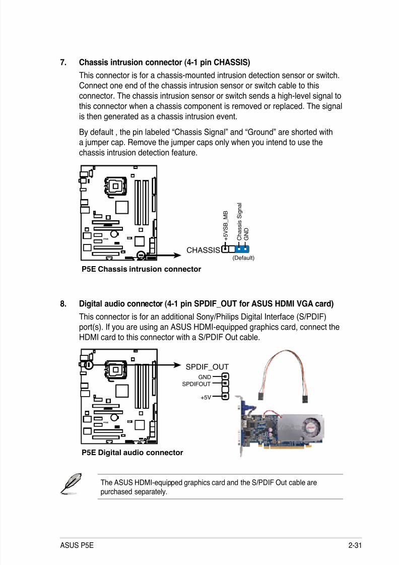
8/13/2019 Asus P5E Motherboard User Guide
http://slidepdf.com/reader/full/asus-p5e-motherboard-user-guide 57/174
ASUS P5E 2-31
7. Chassis intrusion connector (4-1 pin CHASSIS)
This connector is for a chassis-mounted intrusion detection sensor or switch.Connect one end of the chassis intrusion sensor or switch cable to this
connector. The chassis intrusion sensor or switch sends a high-level signal tothis connector when a chassis component is removed or replaced. The signal
is then generated as a chassis intrusion event.
By default , the pin labeled “Chassis Signal” and “Ground” are shorted witha jumper cap. Remove the jumper caps only when you intend to use the
chassis intrusion detection feature.
P5E
®
P5E Chassis intrusion connector
CHASSIS
+ 5 V S B
_ M B
C h a s s
i s S i g n a
l
G N D
(Default)
8. Digital audio connector (4-1 pin SPDIF_OUT for ASUS HDMI VGA card)
This connector is for an additional Sony/Philips Digital Interface (S/PDIF)
port(s). If you are using an ASUS HDMI-equipped graphics card, connect theHDMI card to this connector with a S/PDIF Out cable.
The ASUS HDMI-equipped graphics card and the S/PDIF Out cable arepurchased separately.
P5E
®
P5E Digital audio connector
+5V
SPDIFOUTGND
SPDIF_OUT
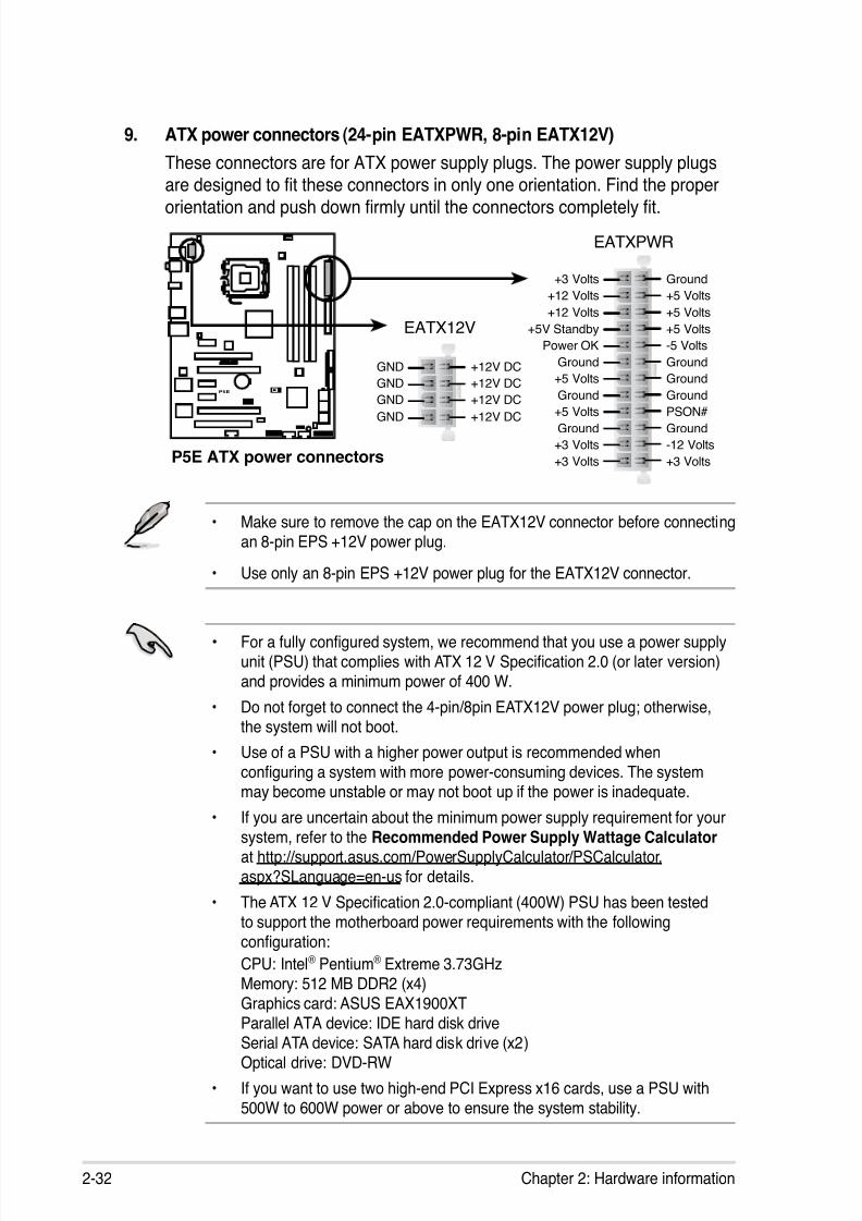
8/13/2019 Asus P5E Motherboard User Guide
http://slidepdf.com/reader/full/asus-p5e-motherboard-user-guide 58/174
2-32 Chapter 2: Hardware information
9. ATX power connectors (24-pin EATXPWR, 8-pin EATX12V)
These connectors are for ATX power supply plugs. The power supply plugs
are designed to t these connectors in only one orientation. Find the proper
orientation and push down rmly until the connectors completely t.
• Make sure to remove the cap on the EATX12V connector before connectingan 8-pin EPS +12V power plug.
• Use only an 8-pin EPS +12V power plug for the EATX12V connector.
P5E
®
P5E ATX power connectors
EATXPWR
EATX12V
+3 Volts
+3 Volts
Ground
+5 Volts
+5 Volts
Ground
Ground
Power OK
+5V Standby
+12 Volts
-5 Volts
+5 Volts
+3 Volts
-12 Volts
Ground
Ground
Ground
PSON#
Ground
+5 Volts
+12 Volts
+3 Volts
+5 Volts
Ground
GND +12V DC
GND +12V DC
GND +12V DC
GND +12V DC
• For a fully congured system, we recommend that you use a power supplyunit (PSU) that complies with ATX 12 V Specication 2.0 (or later version)
and provides a minimum power of 400 W.
• Do not forget to connect the 4-pin/8pin EATX12V power plug; otherwise,
the system will not boot.
• Use of a PSU with a higher power output is recommended whenconguring a system with more power-consuming devices. The system
may become unstable or may not boot up if the power is inadequate.
• If you are uncertain about the minimum power supply requirement for yoursystem, refer to the Recommended Power Supply Wattage Calculator at
http://support.asus.com/PowerSupplyCalculator/PSCalculator.aspx?SLanguage=en-us for details.
• The ATX 12 V Specication 2.0-compliant (400W) PSU has been tested
to support the motherboard power requirements with the followingconguration:
CPU: Intel® Pentium® Extreme 3.73GHz Memory: 512 MB DDR2 (x4)Graphics card: ASUS EAX1900XT
Parallel ATA device: IDE hard disk driveSerial ATA device: SATA hard disk drive (x2)Optical drive: DVD-RW
• If you want to use two high-end PCI Express x16 cards, use a PSU with500W to 600W power or above to ensure the system stability.
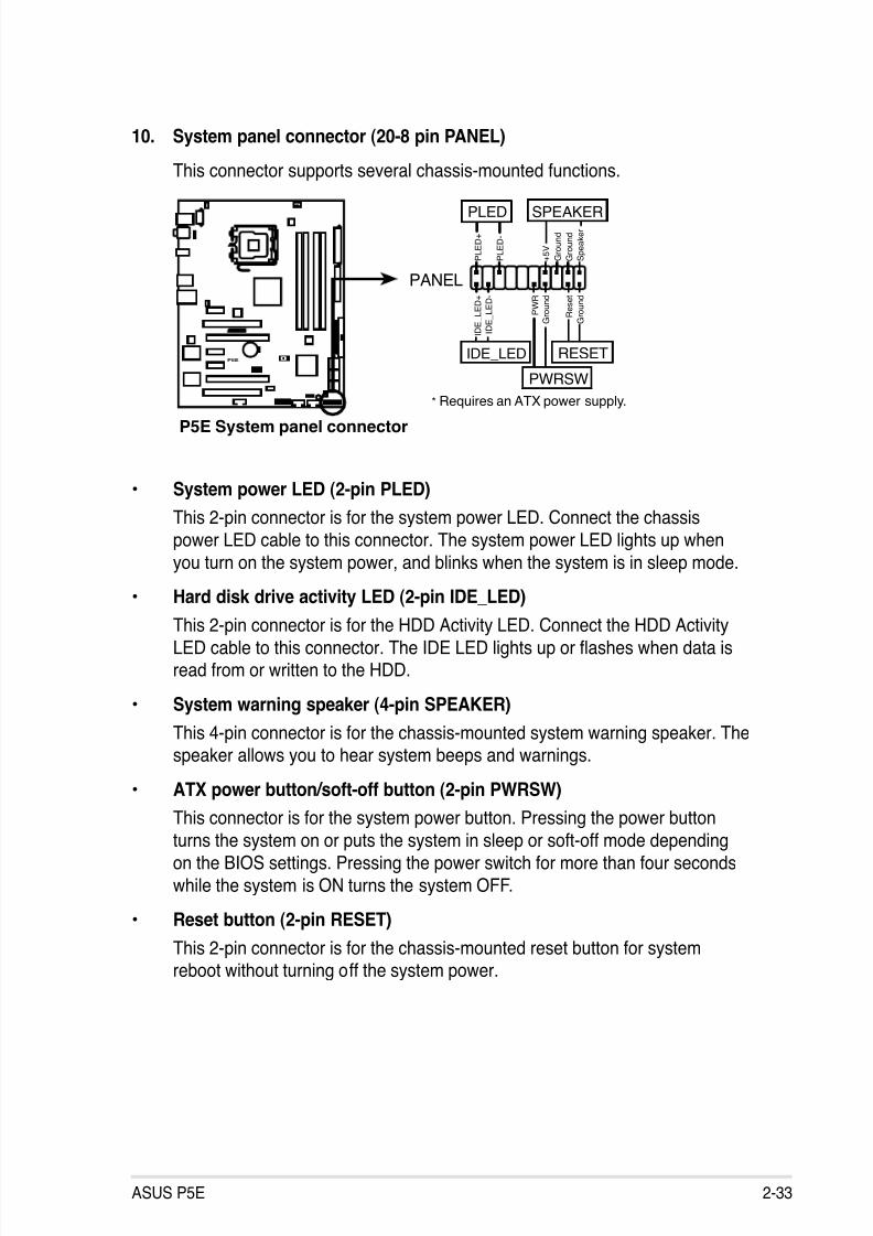
8/13/2019 Asus P5E Motherboard User Guide
http://slidepdf.com/reader/full/asus-p5e-motherboard-user-guide 59/174
ASUS P5E 2-33
• System power LED (2-pin PLED)
This 2-pin connector is for the system power LED. Connect the chassis
power LED cable to this connector. The system power LED lights up when
you turn on the system power, and blinks when the system is in sleep mode.
• Hard disk drive activity LED (2-pin IDE_LED)
This 2-pin connector is for the HDD Activity LED. Connect the HDD ActivityLED cable to this connector. The IDE LED lights up or ashes when data isread from or written to the HDD.
• System warning speaker (4-pin SPEAKER)
This 4-pin connector is for the chassis-mounted system warning speaker. Thespeaker allows you to hear system beeps and warnings.
• ATX power button/soft-off button (2-pin PWRSW)
This connector is for the system power button. Pressing the power buttonturns the system on or puts the system in sleep or soft-off mode depending
on the BIOS settings. Pressing the power switch for more than four seconds
while the system is ON turns the system OFF.
• Reset button (2-pin RESET)
This 2-pin connector is for the chassis-mounted reset button for systemreboot without turning off the system power.
10. System panel connector (20-8 pin PANEL)
This connector supports several chassis-mounted functions.
P5E
®
P5E System panel connector
* Requires an ATX power supply.
PANEL
P L E D -
P W R
+ 5 V
S p e a
k e r
G r o u n
d
RESET
G r o u n
d
R e s e
t
G r o u n
d
G r o u n
d
PWRSW
P L E D +
I D E
_ L E D -
I D E
_ L E D +
IDE_LED
PLED SPEAKER
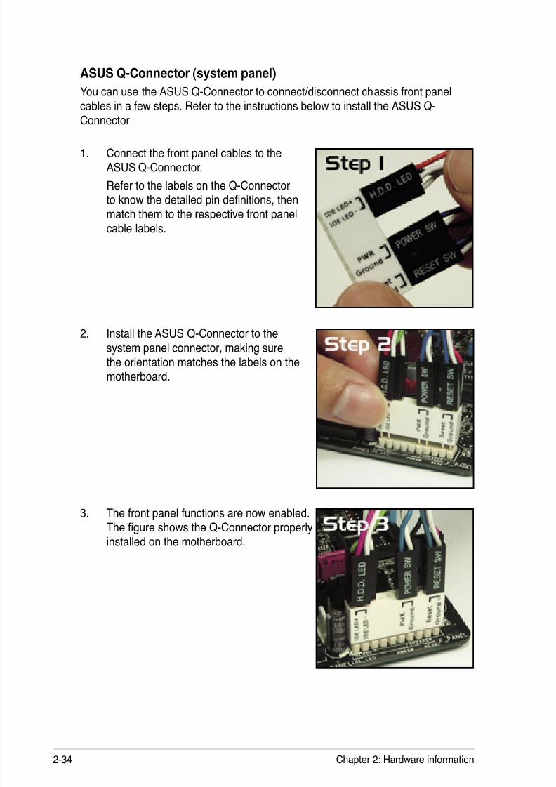
8/13/2019 Asus P5E Motherboard User Guide
http://slidepdf.com/reader/full/asus-p5e-motherboard-user-guide 60/174
2-34 Chapter 2: Hardware information
ASUS Q-Connector (system panel)
You can use the ASUS Q-Connector to connect/disconnect chassis front panel
cables in a few steps. Refer to the instructions below to install the ASUS Q-
Connector.
1. Connect the front panel cables to the
ASUS Q-Connector.
Refer to the labels on the Q-Connector
to know the detailed pin denitions, thenmatch them to the respective front panel
cable labels.
2. Install the ASUS Q-Connector to the
system panel connector, making sure
the orientation matches the labels on themotherboard.
3. The front panel functions are now enabled.
The gure shows the Q-Connector properlyinstalled on the motherboard.

8/13/2019 Asus P5E Motherboard User Guide
http://slidepdf.com/reader/full/asus-p5e-motherboard-user-guide 61/174
3Powering up
This chapter describes the power up
sequence, the vocal POST messages,and ways of shutting down the system.

8/13/2019 Asus P5E Motherboard User Guide
http://slidepdf.com/reader/full/asus-p5e-motherboard-user-guide 62/174
ASUS P5E
Chapter summary
33.1 Starting up for the rst time........................................................ 3-1
3.2 Turning off the computer ............................................................. 3-2
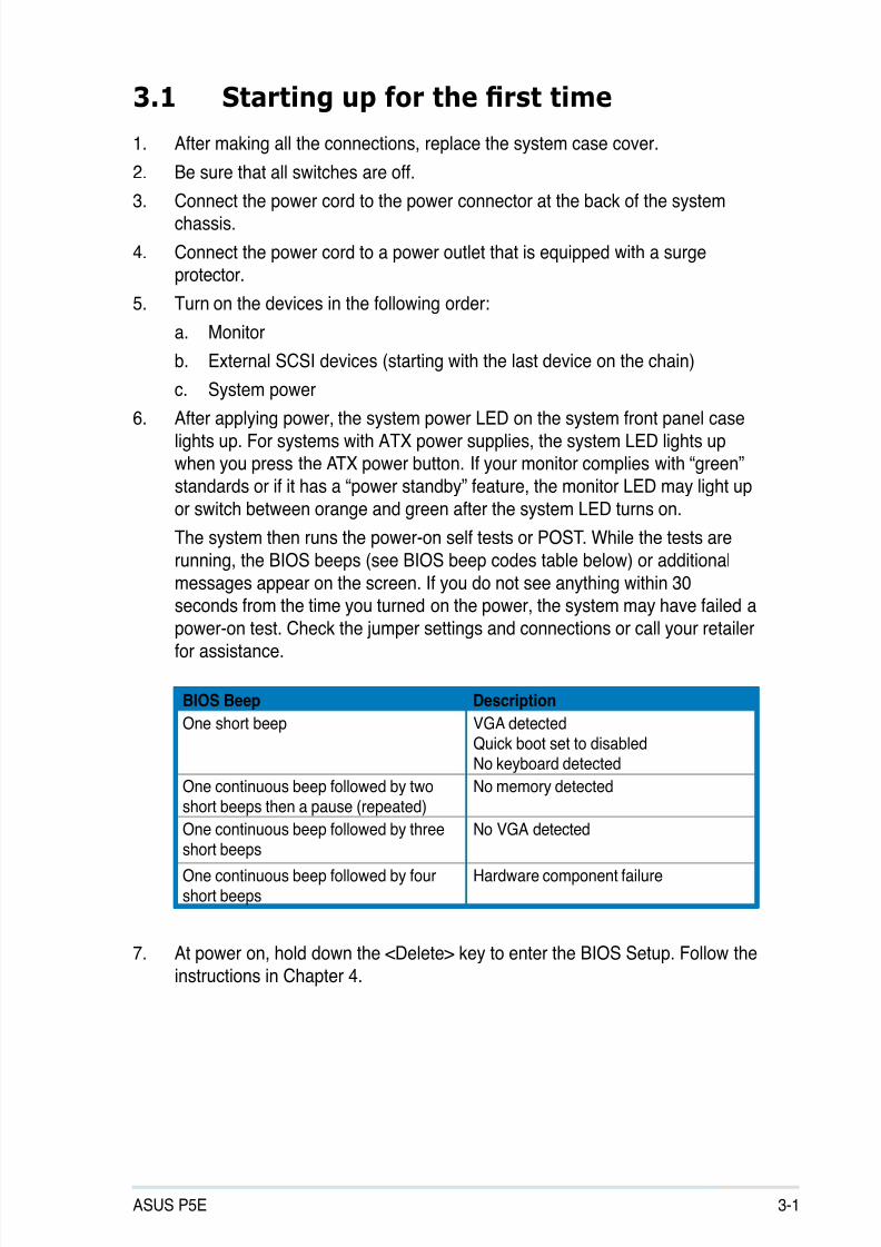
8/13/2019 Asus P5E Motherboard User Guide
http://slidepdf.com/reader/full/asus-p5e-motherboard-user-guide 63/174
ASUS P5E 3-1
3.1 Starting up for the rst time
1. After making all the connections, replace the system case cover.
2. Be sure that all switches are off.
3. Connect the power cord to the power connector at the back of the systemchassis.
4. Connect the power cord to a power outlet that is equipped with a surgeprotector.
5. Turn on the devices in the following order:
a. Monitor
b. External SCSI devices (starting with the last device on the chain)
c. System power
6. After applying power, the system power LED on the system front panel caselights up. For systems with ATX power supplies, the system LED lights upwhen you press the ATX power button. If your monitor complies with “green”
standards or if it has a “power standby” feature, the monitor LED may light up
or switch between orange and green after the system LED turns on.
The system then runs the power-on self tests or POST. While the tests are
running, the BIOS beeps (see BIOS beep codes table below) or additional
messages appear on the screen. If you do not see anything within 30seconds from the time you turned on the power, the system may have failed a
power-on test. Check the jumper settings and connections or call your retailerfor assistance.
7. At power on, hold down the <Delete> key to enter the BIOS Setup. Follow the
instructions in Chapter 4.
BIOS Beep Description
One short beep VGA detectedQuick boot set to disabledNo keyboard detected
One continuous beep followed by twoshort beeps then a pause (repeated)
No memory detected
One continuous beep followed by threeshort beeps
No VGA detected
One continuous beep followed by fourshort beeps
Hardware component failure

8/13/2019 Asus P5E Motherboard User Guide
http://slidepdf.com/reader/full/asus-p5e-motherboard-user-guide 64/174
3-2 Chapter 3: Powering up
3.2 Turning off the computer
3.2.1 Using the OS shut down function
If you are using Windows® XP:
1. Click the Start button then select Turn Off Computer.
2. Click the Turn Off button to shut down the computer.
3. The power supply should turn off after Windows® shuts down.
If you are using Windows® Vista™:
1. Click the Start button then select ShutDown.
2. The power supply should turn off after Windows® shuts down.
3.2.2 Using the dual function power switch
While the system is ON, pressing the power switch for less than four seconds puts
the system to sleep mode or to soft-off mode, depending on the BIOS setting.
Pressing the power switch for more than four seconds lets the system enter thesoft-off mode regardless of the BIOS setting. Refer to section 4.6 Power Menu in
Chapter 4 for details.

8/13/2019 Asus P5E Motherboard User Guide
http://slidepdf.com/reader/full/asus-p5e-motherboard-user-guide 65/174
4BIOS setup
This chapter tells how to change
the system settings through the BIOSSetup menus. Detailed descriptions
of the BIOS parameters are also
provided.
8/13/2019 Asus P5E Motherboard User Guide
http://slidepdf.com/reader/full/asus-p5e-motherboard-user-guide 66/174
Chapter summary 4
ASUS P5E
4.1 Managing and updating your BIOS ............................................ 4-1
4.2 BIOS setup program .................................................................... 4-9
4.3 Main menu .................................................................................. 4-12
4.4 Ai Tweaker .................................................................................. 4-17
4.5 Advanced menu ......................................................................... 4-23
4.6 Power menu ................................................................................ 4-29
4.7 Boot menu .................................................................................. 4-334.8 Tools menu ................................................................................. 4-37
4.9 Exit menu .................................................................................... 4-40
8/13/2019 Asus P5E Motherboard User Guide
http://slidepdf.com/reader/full/asus-p5e-motherboard-user-guide 67/174
ASUS P5E 4-1
4.1 Managing and updating your BIOS
The following utilities allow you to manage and update the motherboard Basic
Input/Output System (BIOS) setup.
1. ASUS Update (Updates the BIOS in Windows® environment.)
2. ASUS EZ Flash 2 (Updates the BIOS using a oppy disk or USB ash disk.)
3. ASUS AFUDOS (Updates the BIOS using a bootable oppy disk)
4. ASUS CrashFree BIOS 3 (Updates the BIOS using a USB ash disk or themotherboard support DVD when the BIOS le fails or gets corrupted.)
Refer to the corresponding sections for details on these utilities.
Save a copy of the original motherboard BIOS le to a bootable oppy disk orUSB ash disk in case you need to restore the BIOS in the future. Copy the
original motherboard BIOS using the ASUS Update or AFUDOS utilities.
Installing ASUS Update
To install ASUS Update:
1. Place the support DVD in the optical drive. The Drivers menu appears.
2. Click the Utilities tab, then click Install ASUS Update VX.XX.XX.
3. The ASUS Update utility is copied to your system.
4.1.1 ASUS Update utility
The ASUS Update is a utility that allows you to manage, save, and update themotherboard BIOS in Windows® environment. The ASUS Update utility allows you
to:
• Save the current BIOS le
• Download the latest BIOS le from the Internet
• Update the BIOS from an updated BIOS le
• Update the BIOS directly from the Internet, and
• View the BIOS version information.
This utility is available in the support DVD that comes with the motherboard
package.
ASUS Update requires an Internet connection either through a network or anInternet Service Provider (ISP).
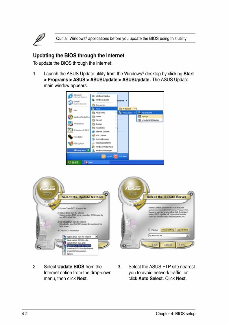
8/13/2019 Asus P5E Motherboard User Guide
http://slidepdf.com/reader/full/asus-p5e-motherboard-user-guide 68/174
4-2 Chapter 4: BIOS setup
Quit all Windows® applications before you update the BIOS using this utility.
3. Select the ASUS FTP site nearest
you to avoid network trafc, orclick Auto Select. Click Next.
Updating the BIOS through the InternetTo update the BIOS through the Internet:
1. Launch the ASUS Update utility from the Windows® desktop by clicking Start> Programs > ASUS > ASUSUpdate > ASUSUpdate. The ASUS Update
main window appears.
2. Select Update BIOS from the
Internet option from the drop-downmenu, then click Next.

8/13/2019 Asus P5E Motherboard User Guide
http://slidepdf.com/reader/full/asus-p5e-motherboard-user-guide 69/174
ASUS P5E 4-3
Updating the BIOS through a BIOS le
To update the BIOS through a BIOS le:
1. Launch the ASUS Update utility from the Windows® desktop by clicking Start > Programs > ASUS > ASUSUpdate > ASUSUpdate. The ASUS Updatemain window appears.
2. Select Update BIOS from a le
option from the drop-down menu,then click Next.
4. From the FTP site, select the BIOSversion that you wish to download.
Click Next.
5. Follow the screen instructions tocomplete the update process.
The ASUS Update utility iscapable of updating itself throughthe Internet. Always update theutility to avail all its features.
3. Locate the BIOS le from the Openwindow, then click Open.
4. Follow the screen instructions to
complete the update process.
P5E
P5E.ROM
8/13/2019 Asus P5E Motherboard User Guide
http://slidepdf.com/reader/full/asus-p5e-motherboard-user-guide 70/174
4-4 Chapter 4: BIOS setup
4.1.2 Creating a bootable oppy disk
1. Do either one of the following to create a bootable oppy disk.
DOS environment
a. Insert a 1.44MB oppy disk into the drive.
b. At the DOS prompt, type format A:/S then press <Enter>.
Windows ® XP environment
a. Insert a 1.44 MB oppy disk to the oppy disk drive.
b. Click Start from the Windows® desktop, then select My Computer.
c. Select the 3 1/2 Floppy Drive icon.
d. Click File from the menu, then select Format. A Format 3 1/2 Floppy
Disk window appears.
e. Select Create an MS-DOS startup disk from the format options eld,then click Start.
2. Copy the original or the latest motherboard BIOS le to the bootable oppydisk.

8/13/2019 Asus P5E Motherboard User Guide
http://slidepdf.com/reader/full/asus-p5e-motherboard-user-guide 71/174
ASUS P5E 4-5
To update the BIOS using EZ Flash 2:
1. Visit the ASUS website (www.asus.com) to download the latest BIOS le forthe motherboard.
2. Save the BIOS le to a oppy disk or a USB ash disk, then restart thesystem.
4.1.3 ASUS EZ Flash 2 utility
The ASUS EZ Flash 2 feature allows you to update the BIOS without having to go
through the long process of booting from a oppy disk and using a DOS-based
utility. The EZ Flash 2 utility is built-in the BIOS chip so it is accessible by pressing<Alt> + <F2> during the Power-On Self Tests (POST).
(2) Enter BIOS setup program. Go to the Tools menu to select EZ Flash2
and press <Enter> to enable it.
You can switch between drives by pressing <Tab> before the correct leis found. Then press <Enter>.
3. You can launch the EZ Flash 2 by two methods.
(1) Insert the oppy disk / USB ash disk that contains the BIOS le to theoppy disk drive or the USB port.
Press <Alt> + <F2> during POST to display the following.
• This function can support devices such as USB ash disk, or oppy disk
with FAT 32/16 format and single partition only.
• DO NOT shut down or reset the system while updating the BIOS to preventsystem boot failure!
4. When the correct BIOS le is found, EZ Flash 2 performs the BIOS update
process and automatically reboots the system when done.
ASUSTek EZ Flash 2 BIOS ROM Utility V3.06
Current ROM Update ROM
A:
Note [Enter] Select or Load [B] Backup [ESC] Exit
[Tab] Switch [Up/Down/Home/End] Move
FLASH TYPE: MXIC 25L1605A
PATH: A:\
BOARD: P5E
VER: 0102DATE: 08/24/07
BOARD: Unknown
VER: UnknownDATE: Unknown
8/13/2019 Asus P5E Motherboard User Guide
http://slidepdf.com/reader/full/asus-p5e-motherboard-user-guide 72/174
4-6 Chapter 4: BIOS setup
4.1.4 AFUDOS utility
The AFUDOS utility allows you to update the BIOS le in DOS environment usinga bootable oppy disk with the updated BIOS le. This utility also allows you to
copy the current BIOS le that you can use as backup when the BIOS fails or getscorrupted during the updating process.
Copying the current BIOS
To copy the current BIOS le using the AFUDOS utility:
Main lename Extension name
1. Copy the AFUDOS utility (afudos.exe) from the motherboard support DVD to
the bootable oppy disk you created earlier.
2. Boot the system in DOS mode, then at the prompt type:
afudos /o[lename]
where the [lename] is any user-assigned lename not more than eightalphanumeric characters for the main lename and three alphanumeric
characters for the extension name. A:\>afudos /oOLDBIOS1.rom
• Make sure that the oppy disk is not write-protected and has at least
1024KB free space to save the le.
• The succeeding BIOS screens are for reference only. The actual BIOS
screen displays may not be same as shown.
The utility returns to the DOS prompt after copying the current BIOS le.
3. Press <Enter>. The utility copies the current BIOS le to the oppy disk.
A:\>afudos /oOLDBIOS1.rom
AMI Firmware Update Utility - Version 1.19(ASUS V2.07(03.11.24BB))
Copyright (C) 2002 American Megatrends, Inc. All rights reserved.
Reading ash ..... done
Write to le...... ok
A:\>
Updating the BIOS le
To update the BIOS le using the AFUDOS utility:
1. Visit the ASUS website (www.asus.com) and download the latest BIOS le forthe motherboard. Save the BIOS le to a bootable oppy disk.
8/13/2019 Asus P5E Motherboard User Guide
http://slidepdf.com/reader/full/asus-p5e-motherboard-user-guide 73/174
ASUS P5E 4-7
2. Copy the AFUDOS utility (afudos.exe) from the motherboard support DVD to
the bootable oppy disk you created earlier.3. Boot the system in DOS mode, then at the prompt type:
afudos /i[lename]
where [lename] is the latest or the original BIOS le on the bootable oppydisk.
A:\>afudos /iP5E.ROM
Write the BIOS lename on a piece of paper. You need to type the exact BIOS
lename at the DOS prompt.
5. The utility returns to the DOS prompt after the BIOS update process is
completed. Reboot the system from the hard disk drive.
A:\>afudos /iP5E.ROM
AMI Firmware Update Utility - Version 1.19(ASUS V2.07(03.11.24BB))
Copyright (C) 2002 American Megatrends, Inc. All rights reserved.
WARNING!! Do not turn off power during ash BIOS
Reading le ....... done
Reading ash ...... done
Advance Check ......
Erasing ash ...... done
Writing ash ...... done
Verifying ash .... done
Please restart your computer
A:\>
A:\>afudos /iP5E.ROM
AMI Firmware Update Utility - Version 1.19(ASUS V2.07(03.11.24BB))
Copyright (C) 2002 American Megatrends, Inc. All rights reserved.
WARNING!! Do not turn off power during ash BIOS
Reading le ....... done
Reading ash ...... done
Advance Check ......
Erasing ash ...... done
Writing ash ...... 0x0008CC00 (9%)
4. The utility veries the le and starts updating the BIOS.
DO NOT shut down or reset the system while updating the BIOS to preventsystem boot failure!
8/13/2019 Asus P5E Motherboard User Guide
http://slidepdf.com/reader/full/asus-p5e-motherboard-user-guide 74/174
4-8 Chapter 4: BIOS setup
4.1.5 ASUS CrashFree BIOS 3 utility
The ASUS CrashFree BIOS 3 is an auto recovery tool that allows you to restore
the BIOS le when it fails or gets corrupted during the updating process. You can
update a corrupted BIOS le using the motherboard support DVD or the USB ashdisk that contains the updated BIOS le.
• Prepare the motherboard support DVD, the oppy disk or the USB ash
disk containing the updated motherboard BIOS before using this utility.
• If you use a SATA optical drive, always connect the SATA cable to theSATA1/SATA 2/SATA3/SATA4 connector; otherwise, the utility will not
function.
Recovering the BIOS from the support DVD
To recover the BIOS from the support DVD:
1. Turn on the system.
2. Insert the motherboard support DVD to the optical drive.
3. The utility displays the following message and automatically checks the DVD
for the BIOS le.
4. Restart the system after the utility completes the updating process.
• Only the USB ash disk with FAT 32/16 format and single partition cansupport ASUS CrashFree BIOS 3. The device size should be smaller than
8GB.
• DO NOT shut down or reset the system while updating the BIOS! Doing socan cause system boot failure!
When found, the utility reads the BIOS le and starts ashing the corruptedBIOS le.
Recovering the BIOS from the USB ash diskTo recover the BIOS from the USB ash disk:
1. Insert the USB ash disk that contains BIOS le to the USB port.
2. Turn on the system.
3. The utility will automatically checks the devices for the BIOS le When found,the utility reads the BIOS le and starts ashing the corrupted BIOS le.
4. Restart the system after the utility completes the updating process.
Bad BIOS checksum. Starting BIOS recovery...
Checking for oppy...
Bad BIOS checksum. Starting BIOS recovery...
Checking for oppy...
Floppy found!
Reading le “P5E.ROM”. Completed.
Start ashing...

8/13/2019 Asus P5E Motherboard User Guide
http://slidepdf.com/reader/full/asus-p5e-motherboard-user-guide 75/174
ASUS P5E 4-9
4.2 BIOS setup program
This motherboard supports a programmable Serial Peripheral Interface (SPI) chipthat you can update using the provided utility described in section 4.1 Managingand updating your BIOS.
Use the BIOS Setup program when you are installing a motherboard, reconguringyour system, or prompted to “Run Setup.” This section explains how to congureyour system using this utility.
Even if you are not prompted to use the Setup program, you can change the
conguration of your computer in the future. For example, you can enable thesecurity password feature or change the power management settings. This
requires you to recongure your system using the BIOS Setup program so that thecomputer can recognize these changes and record them in the CMOS RAM of theSPI chip.
The SPI chip on the motherboard stores the Setup utility. When you start up the
computer, the system provides you with the opportunity to run this program. Press
<Del> during the Power-On Self-Test (POST) to enter the Setup utility; otherwise,POST continues with its test routines.
If you wish to enter Setup after POST, restart the system by pressing
<Ctrl+Alt+Delete>, or by pressing the reset button on the system chassis. You can
also restart by turning the system off and then back on. Do this last option only if
the rst two failed.
The Setup program is designed to make it as easy to use as possible. Being a
menu-driven program, it lets you scroll through the various sub-menus and make
your selections from the available options using the navigation keys.
• The default BIOS settings for this motherboard apply for most conditionsto ensure optimum performance. If the system becomes unstable afterchanging any BIOS settings, load the default settings to ensure systemcompatibility and stability. Select the Load Setup Defaults item under the
Exit Menu. See section 4.9 Exit Menu.
• The BIOS setup screens shown in this section are for reference purposesonly, and may not exactly match what you see on your screen.
• Visit the ASUS website (www.asus.com) to download the latest BIOS le for
this motherboard.

8/13/2019 Asus P5E Motherboard User Guide
http://slidepdf.com/reader/full/asus-p5e-motherboard-user-guide 76/174
4-10 Chapter 4: BIOS setup
Select Screen Select Item
+- Change Field
Tab Select Field F1 General HelpF10 Save and ExitESC Exit
v02.61 (C)Copyright 1985-2007, American Megatrends, Inc.
BIOS SETUP UTILITY Main Ai Tweaker Advanced Power Boot Tools Exit
System Time [10:55:25] System Date [Mon 07/23/2007]Legacy Diskette A [1.44M, 3.5 in.]Language [English]
SATA1 [Not Detected] SATA2 [Not Detected] SATA3 [Not Detected] SATA4 [Not Detected] SATA5 [Not Detected] SATA6 [Not Detected]
SATA Conguration
System Information
Use [ENTER], [TAB]or [SHIFT-TAB] toselect a eld.
Use [+] or [-] tocongure the SystemTime.
4.2.2 Menu bar
The menu bar on top of the screen has the following main items:
Main For changing the basic system conguration
Ai Tweaker For changing the overclocking settings
Advanced For changing the advanced system settings
Power For changing the advanced power management (APM)
conguration
Boot For changing the system boot conguration
Tools For conguring options for special functionsExit For selecting the exit options and loading default
settings
To select an item on the menu bar, press the right or left arrow key on the keyboard
until the desired item is highlighted.
4.2.3 Navigation keys
At the bottom right corner of a menu screen are the navigation keys for that
particular menu. Use the navigation keys to select items in the menu and changethe settings.
4.2.1 BIOS menu screen
The navigation keys may differ from one screen to another.
Navigation keys
General helpMenu bar
Sub-menu items
Conguration eldsMenu items

8/13/2019 Asus P5E Motherboard User Guide
http://slidepdf.com/reader/full/asus-p5e-motherboard-user-guide 77/174
ASUS P5E 4-11
4.2.4 Menu items
The highlighted item on the menu bar
displays the specic items for that
menu. For example, selecting Mainshows the Main menu items.
The other items (Advanced, Power,
Boot, and Exit) on the menu bar have
their respective menu items.
4.2.5 Sub-menu items
A solid triangle before each item on any menu screen means that the iteam has a
sub-menu. To display the sub-menu, select the item and press <Enter>.
4.2.6 Conguration elds
These elds show the values for the menu items. If an item is user- congurable,you can change the value of the eld opposite the item. You cannot select an itemthat is not user-congurable.
A congurable eld is enclosed in brackets, and is highlighted when selected. Tochange the value of a eld, select it then press <Enter> to display a list of options.Refer to 4.2.7 Pop-up window.
4.2.7 Pop-up window
Select a menu item then press <Enter> to display a pop-up window with the
conguration options for that item.
4.2.8 Scroll bar
A scroll bar appears on the right side of a
menu screen when there are items that do
not t on the screen. Press theUp/Down arrow keys or <Page Up> /<Page
Down> keys to display the other items on
the screen.
4.2.9 General help
At the top right corner of the menu screen
is a brief description of the selected item.
Main menu items
Scroll bar
Pop-up window
System Time [06:22:54]
System Date [Mon 04/23/2007]
Floppy Diskette A [1.44M, 3.5 in.]
Language [English]
SATA1 [Not Detected]
SATA2 [Not Detected]
SATA3 [Not Detected]
SATA4 [Not Detected]
SATA5 [Not Detected]
SATA6 [Not Detected]
SATA Conguration
System Information
Use [ENTER], [TAB],
or [SHIFT-TAB] to
select a eld.
Use [+] or [-] to
congure system.
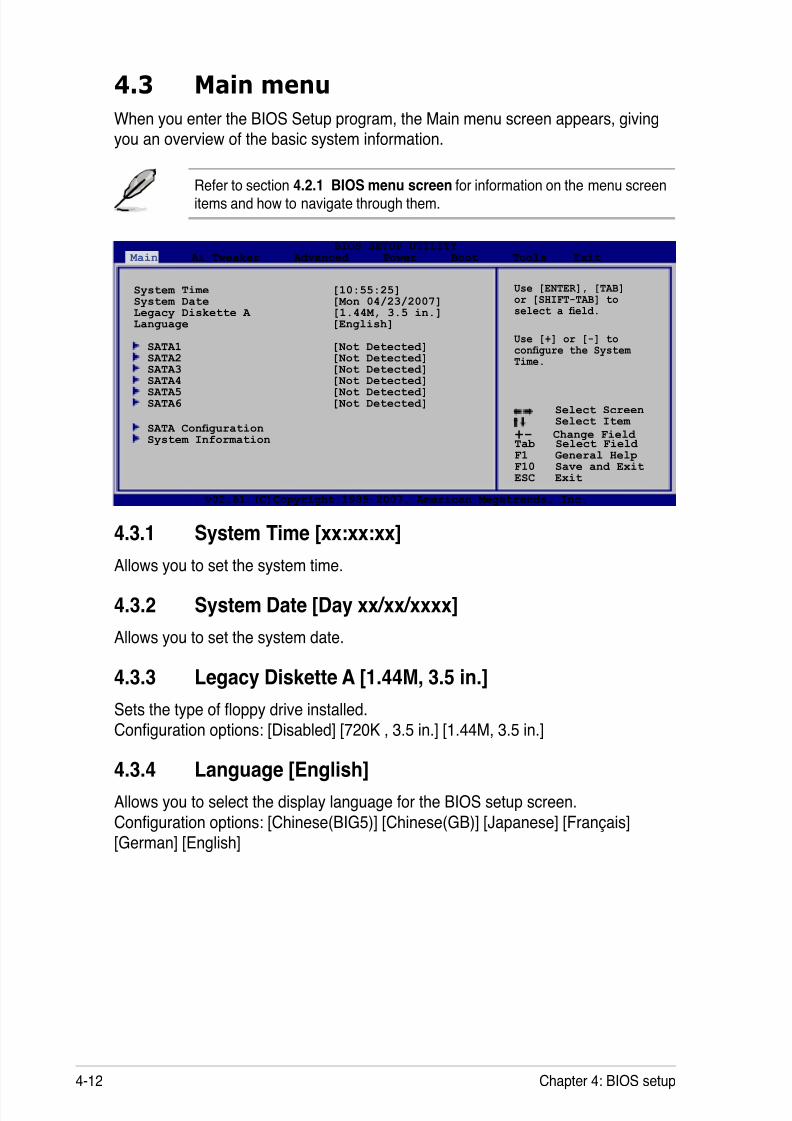
8/13/2019 Asus P5E Motherboard User Guide
http://slidepdf.com/reader/full/asus-p5e-motherboard-user-guide 78/174
4-12 Chapter 4: BIOS setup
4.3 Main menu
When you enter the BIOS Setup program, the Main menu screen appears, givingyou an overview of the basic system information.
4.3.1 System Time [xx:xx:xx]
Allows you to set the system time.
4.3.2 System Date [Day xx/xx/xxxx]
Allows you to set the system date.
4.3.3 Legacy Diskette A [1.44M, 3.5 in.] Sets the type of oppy drive installed.
Conguration options: [Disabled] [720K , 3.5 in.] [1.44M, 3.5 in.]
4.3.4 Language [English]
Allows you to select the display language for the BIOS setup screen.
Conguration options: [Chinese(BIG5)] [Chinese(GB)] [Japanese] [Français][German] [English]
Refer to section 4.2.1 BIOS menu screen for information on the menu screenitems and how to navigate through them.
Select Screen Select Item
+- Change Field Tab Select Field F1 General HelpF10 Save and ExitESC Exit
v02.61 (C)Copyright 1985-2007, American Megatrends, Inc.
BIOS SETUP UTILITY Main Ai Tweaker Advanced Power Boot Tools Exit
System Time [10:55:25] System Date [Mon 04/23/2007]Legacy Diskette A [1.44M, 3.5 in.]Language [English]
SATA1 [Not Detected] SATA2 [Not Detected]
SATA3 [Not Detected] SATA4 [Not Detected] SATA5 [Not Detected] SATA6 [Not Detected]
SATA Conguration System Information
Use [ENTER], [TAB]or [SHIFT-TAB] toselect a eld.
Use [+] or [-] tocongure the SystemTime.
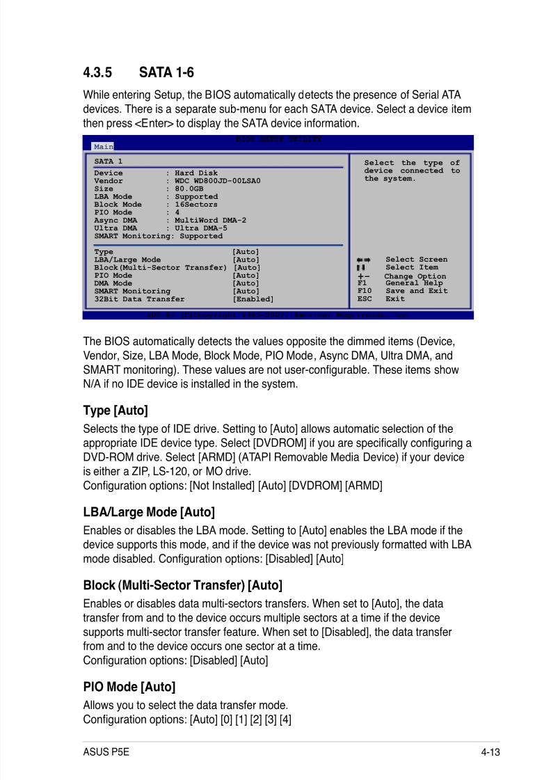
8/13/2019 Asus P5E Motherboard User Guide
http://slidepdf.com/reader/full/asus-p5e-motherboard-user-guide 79/174
ASUS P5E 4-13
4.3.5 SATA 1-6
While entering Setup, the BIOS automatically detects the presence of Serial ATA
devices. There is a separate sub-menu for each SATA device. Select a device item
then press <Enter> to display the SATA device information.
Select Screen Select Item
+- Change OptionF1 General HelpF10 Save and ExitESC Exit
v02.61 (C)Copyright 1985-2007, American Megatrends, Inc.
BIOS SETUP UTILITY Main
SATA 1
Device : Hard Disk Vendor : WDC WD800JD-00LSA0Size : 80.0GBLBA Mode : Supported Block Mode : 16SectorsPIO Mode : 4 Async DMA : MultiWord DMA-2Ultra DMA : Ultra DMA-5SMART Monitoring: Supported
Type [Auto]
LBA/Large Mode [Auto]Block(Multi-Sector Transfer) [Auto]PIO Mode [Auto]DMA Mode [Auto]SMART Monitoring [Auto]32Bit Data Transfer [Enabled]
Select the type ofdevice connected tothe system.
The BIOS automatically detects the values opposite the dimmed items (Device,
Vendor, Size, LBA Mode, Block Mode, PIO Mode, Async DMA, Ultra DMA, andSMART monitoring). These values are not user-congurable. These items showN/A if no IDE device is installed in the system.
Type [Auto]
Selects the type of IDE drive. Setting to [Auto] allows automatic selection of the
appropriate IDE device type. Select [DVDROM] if you are specically conguring aDVD-ROM drive. Select [ARMD] (ATAPI Removable Media Device) if your device
is either a ZIP, LS-120, or MO drive.
Conguration options: [Not Installed] [Auto] [DVDROM] [ARMD]
LBA/Large Mode [Auto]
Enables or disables the LBA mode. Setting to [Auto] enables the LBA mode if thedevice supports this mode, and if the device was not previously formatted with LBA
mode disabled. Conguration options: [Disabled] [Auto]
Block (Multi-Sector Transfer) [Auto]
Enables or disables data multi-sectors transfers. When set to [Auto], the data
transfer from and to the device occurs multiple sectors at a time if the device
supports multi-sector transfer feature. When set to [Disabled], the data transfer
from and to the device occurs one sector at a time.Conguration options: [Disabled] [Auto]
PIO Mode [Auto]
Allows you to select the data transfer mode.
Conguration options: [Auto] [0] [1] [2] [3] [4]
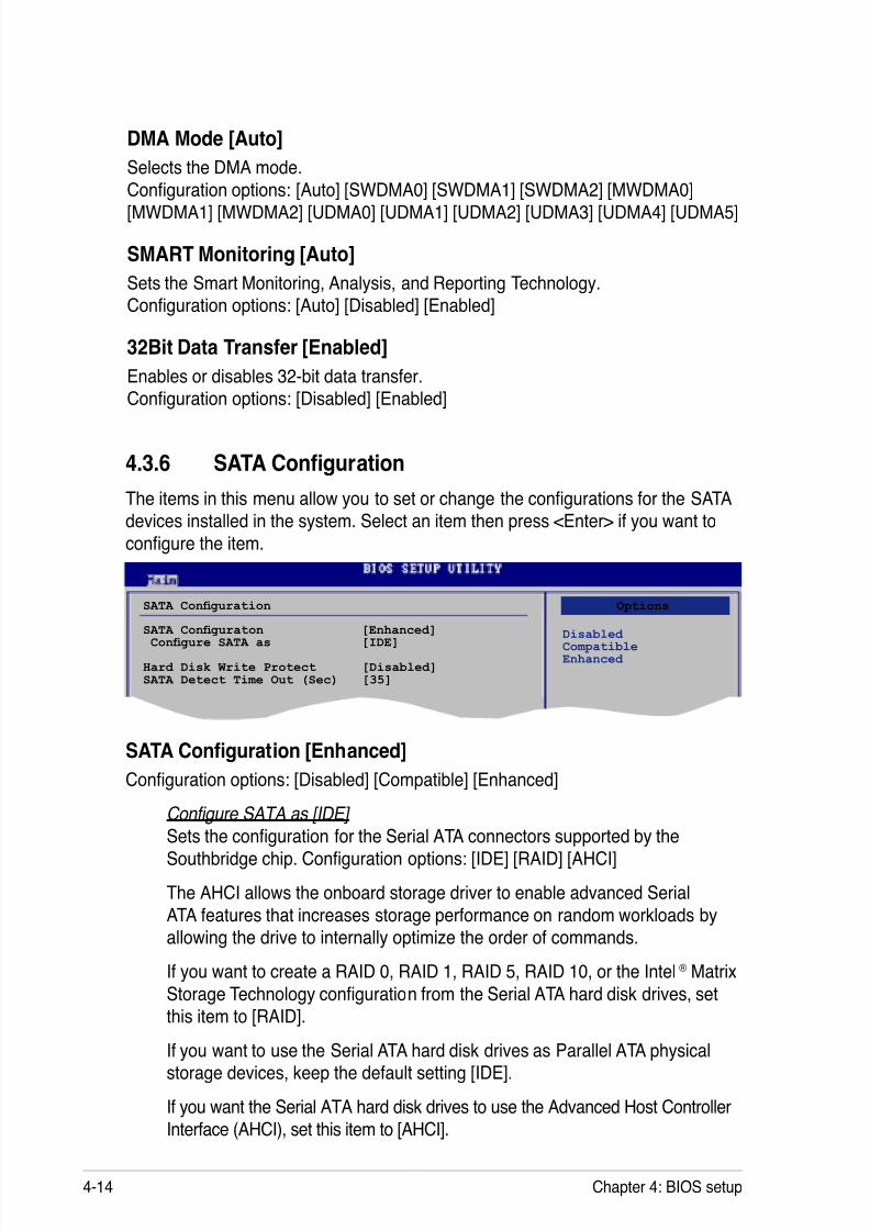
8/13/2019 Asus P5E Motherboard User Guide
http://slidepdf.com/reader/full/asus-p5e-motherboard-user-guide 80/174
4-14 Chapter 4: BIOS setup
DMA Mode [Auto]
Selects the DMA mode.
Conguration options: [Auto] [SWDMA0] [SWDMA1] [SWDMA2] [MWDMA0]
[MWDMA1] [MWDMA2] [UDMA0] [UDMA1] [UDMA2] [UDMA3] [UDMA4] [UDMA5]
SMART Monitoring [Auto]
Sets the Smart Monitoring, Analysis, and Reporting Technology.
Conguration options: [Auto] [Disabled] [Enabled]
32Bit Data Transfer [Enabled]
Enables or disables 32-bit data transfer.
Conguration options: [Disabled] [Enabled]
SATA Conguration [Enhanced]
Conguration options: [Disabled] [Compatible] [Enhanced]
Configure SATA as [IDE] Sets the conguration for the Serial ATA connectors supported by theSouthbridge chip. Conguration options: [IDE] [RAID] [AHCI]
The AHCI allows the onboard storage driver to enable advanced Serial
ATA features that increases storage performance on random workloads by
allowing the drive to internally optimize the order of commands.
If you want to create a RAID 0, RAID 1, RAID 5, RAID 10, or the Intel ® Matrix
Storage Technology conguration from the Serial ATA hard disk drives, setthis item to [RAID].
If you want to use the Serial ATA hard disk drives as Parallel ATA physicalstorage devices, keep the default setting [IDE].
If you want the Serial ATA hard disk drives to use the Advanced Host Controller
Interface (AHCI), set this item to [AHCI].
SATA Conguration
SATA Conguraton [Enhanced] Congure SATA as [IDE]
Hard Disk Write Protect [Disabled]SATA Detect Time Out (Sec) [35]
4.3.6 SATA Conguration
The items in this menu allow you to set or change the congurations for the SATAdevices installed in the system. Select an item then press <Enter> if you want to
congure the item.
Options
Disabled CompatibleEnhanced
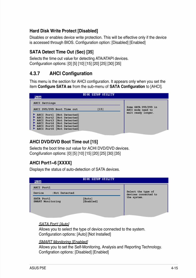
8/13/2019 Asus P5E Motherboard User Guide
http://slidepdf.com/reader/full/asus-p5e-motherboard-user-guide 81/174
ASUS P5E 4-15
Hard Disk Write Protect [Disabled]
Disables or enables device write protection. This will be effective only if the device
is accessed through BIOS. Conguration option: [Disabled] [Enabled]
SATA Detect Time Out (Sec) [35]
Selects the time out value for detecting ATA/ATAPI devices.
Conguration options: [0] [5] [10] [15] [20] [25] [30] [35]
SATA Port1 [Auto]
Allows you to select the type of device connected to the system.
Conguration options: [Auto] [Not Installed]
SMART Monitoring [Enabled]
Allows you to set the Self-Monitoring, Analysis and Reporting Technology.
Congration options: [Disabled] [Enabled]
4.3.7 AHCI Conguration
This menu is the section for AHCI conguration. It appears only when you set theitem Congure SATA as from the sub-menu of SATA Conguration to [AHCI].
AHCI Port1~6 [XXXX]
Displays the status of auto-detection of SATA devices.
AHCI Port1
Device :Not Detected
SATA Port1 [Auto]SMART Monitoring [Enabled]
Select the type ofdevices connected tothe system.
AHCI Settings
AHCI DVD/DVD Boot Time out [15]
AHCI Port1 [Not Detected] AHCI Port2 [Not Detected] AHCI Port3 [Not Detected] AHCI Port4 [Not Detected] AHCI Port5 [Not Detected] AHCI Port6 [Not Detected]
Some SATA DVD/DVD in AHCI mode need to wait ready longer.
AHCI DVD/DVD Boot Time out [15]
Selects the boot time out value for ACHI DVD/DVD devices.
Congifuration options: [0] [5] [10] [15] [20] [25] [30] [35]
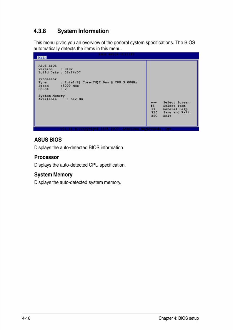
8/13/2019 Asus P5E Motherboard User Guide
http://slidepdf.com/reader/full/asus-p5e-motherboard-user-guide 82/174
4-16 Chapter 4: BIOS setup
4.3.8 System Information
This menu gives you an overview of the general system specications. The BIOSautomatically detects the items in this menu.
ASUS BIOS
Displays the auto-detected BIOS information.
Processor
Displays the auto-detected CPU specication.
System Memory
Displays the auto-detected system memory.
Select Screen Select Item
F1 General HelpF10 Save and ExitESC Exit
v02.61 (C)Copyright 1985-2007, American Megatrends, Inc.
BIOS SETUP UTILITY Main
ASUS BIOS Version : 0102Build Date : 08/24/07
ProcessorType : Intel(R) Core(TM)2 Duo @ CPU 3.00GHzSpeed :3000 MHzCount : 2
System Memory Available : 512 MB
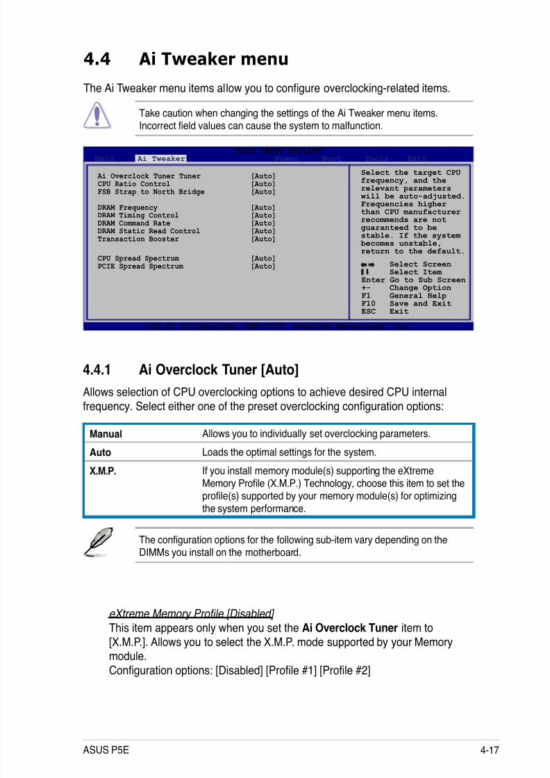
8/13/2019 Asus P5E Motherboard User Guide
http://slidepdf.com/reader/full/asus-p5e-motherboard-user-guide 83/174
ASUS P5E 4-17
4.4 Ai Tweaker menu
The Ai Tweaker menu items allow you to congure overclocking-related items.
Take caution when changing the settings of the Ai Tweaker menu items.
Incorrect eld values can cause the system to malfunction.
Select Screen Select Item
Enter Go to Sub Screen+- Change OptionF1 General HelpF10 Save and ExitESC Exit
v02.61 (C)Copyright 1985-2007, American Megatrends, Inc.
BIOS SETUP UTILITY Main Ai Tweaker Power Boot Tools Exit
Ai Overclock Tuner Tuner [Auto]CPU Ratio Control [Auto]FSB Strap to North Bridge [Auto]
DRAM Frequency [Auto]DRAM Timing Control [Auto]DRAM Command Rate [Auto]DRAM Static Read Control [Auto]Transaction Booster [Auto]
CPU Spread Spectrum [Auto]PCIE Spread Spectrum [Auto]
Select the target CPUfrequency, and therelevant parameters will be auto-adjusted.Frequencies higherthan CPU manufacturerrecommends are notguaranteed to bestable. If the system becomes unstable,return to the default.
4.4.1 Ai Overclock Tuner [Auto]
Allows selection of CPU overclocking options to achieve desired CPU internalfrequency. Select either one of the preset overclocking conguration options:
Manual Allows you to individually set overclocking parameters.
Auto Loads the optimal settings for the system.
X.M.P. If you install memory module(s) supporting the eXtremeMemory Prole (X.M.P.) Technology, choose this item to set theprole(s) supported by your memory module(s) for optimizing
the system performance.
The conguration options for the following sub-item vary depending on the
DIMMs you install on the motherboard.
eXtreme Memory Profile [Disabled]
This item appears only when you set the Ai Overclock Tuner item to
[X.M.P.]. Allows you to select the X.M.P. mode supported by your Memorymodule.
Conguration options: [Disabled] [Prole #1] [Prole #2]

8/13/2019 Asus P5E Motherboard User Guide
http://slidepdf.com/reader/full/asus-p5e-motherboard-user-guide 84/174
4-18 Chapter 4: BIOS setup
FSB Frequency [XXX]
Displays the frequency sent by the clock generator to the system bus and PCI bus.
The value of this item is auto-detected by the BIOS. Use the <+> and <-> keys to
adjust the FSB frequency. You can also type the desired CPU frequency using thenumeric keypad. The values range from 200 to 800. Refer to the table below for
the correct Front Side Bus and CPU External Frequency settings.
FSB/CPU External Frequency Synchronization
Front Side Bus CPU External Frequency
FSB 1333 333 MHz
FSB 1066 266 MHz
FSB 800 200 MHz
4.4.2 CPU Ratio Control [Auto]
Conguration options: [Auto] [Manual].
Ratio CMOS Setting [9] This sub-item appears only when you set the CPU Ratio Control item to[Manual]. Allows you to set the ratio between CPU Core Clock and FSB
Frequency. Use the <+> and <-> keys to adjust the ratio. If an invalid ratio is
set in CMOS, then actual and setpoint values may differ.
4.4.3 FSB Strap to North Bridge [Auto]
When set to [Auto], the FSB Strap will be adjusted automatically by FSB
Frequency and DRAM Frequency.
Congifuration options: [Auto] [200MHz] [266MHz] [333MHz]
The following item appears only when you set the Ai Overclock Tuner item to
The following item appears only when you set the Ai Overclock Tuner item to
PCIE Frequency [Auto]
Allows you to set the PCI Express frequency. Use the <+> and <-> keys to adjust
the PCIE frequency. The values range from 100 to 150.
8/13/2019 Asus P5E Motherboard User Guide
http://slidepdf.com/reader/full/asus-p5e-motherboard-user-guide 85/174
ASUS P5E 4-19
CAS# Latency [5 DRAM Clocks]
Conguration options: [3 DRAM Clocks] [4 DRAM Clocks] [5 DRAM Clocks][6 DRAM Clocks].....[17 DRAM Clocks] [18 DRAM Clocks]
RAS# to CAS# Delay [5 DRAM Clocks]
Conguration options: [3 DRAM Clocks] [4 DRAM Clocks] [5 DRAM Clocks][6 DRAM Clocks].....[17 DRAM Clocks] [18 DRAM Clocks]
RAS# Precharge [5 DRAM Clocks]
Conguration options: [3 DRAM Clocks] [4 DRAM Clocks] [5 DRAM Clocks][6 DRAM Clocks].....[17 DRAM Clocks] [18 DRAM Clocks]
RAS# Active Time [15 DRAM Clocks] Conguration options: [ 3 DRAM Clocks] [4 DRAM Clocks] [5 DRAM Clocks][6 DRAM Clocks].....[33 DRAM Clocks] [34 DRAM Clocks]
RAS# to RAS# Delay [Auto]
Conguration options: [Auto] [1 DRAM Clocks]~[15 DRAM Clocks]
Row Refresh Cycle Time [Auto]
Conguration options: [Auto] [20 DRAM Clocks] [25 DRAM Clocks] [30 DRAM Clocks] [35 DRAM Clocks] [42 DRAM Clocks]
Write Recovery Time [Auto] Conguration options: [Auto] [1 DRAM Clocks]~[15 DRAM Clocks]
Write to Read Delay [Auto]
Conguration options: [Auto] [1 DRAM Clocks]~[15 DRAM Clocks]
The DRAM Frequency conguration options vary with the FSB Frequency settings.
Selecting a very high DRAM frequency may cause the system to become
unstable! If this happens, revert to the default setting.
4.4.4 DRAM Frequency [Auto]
Allows you to set the DDR2 operating frequency.
Conguration options: [Auto] [DDR2-667 MHz] [DDR2-800MHz] [DDR2-835MHz][DDR2-1002MHz] [DDR2-1066] [DDR2-1111] [DDR2-1333]
4.4.5 DRAM Timing Control [Auto]
Conguration options: [Auto] [Manual]
• The following sub-items apprear only when you set the DRAM TimingControl item to [Manual].
• The conguration options for some of the following items vary depending
on the DIMMs you install on the motherboard.

8/13/2019 Asus P5E Motherboard User Guide
http://slidepdf.com/reader/full/asus-p5e-motherboard-user-guide 86/174
4-20 Chapter 4: BIOS setup
Read to Precharge Time [Auto]
Conguration options: [Auto] [1 DRAM Clocks]~[15 DRAM Clocks]
4.4.6 DRAM Command Rate [Auto]Conguration options: [Auto] [1T] [2T]
4.4.7 DRAM Static Read Control [Auto]
Conguration options: [Auto] [Disabled] [Enabled]
4.4.8 Transaction Booster [Auto]
Conguration options: [Auto] [Disabled] [Enabled]
Boost Level [0] This sub-item appears only when you set the Transaction Booster item to[Enabled]. Set this item to a higher level to get better performance. Use the
<+> and <-> keys to adjust the value. The values range from 0 to 3.
Relax Level [0]
This sub-item appears only when you set the Transaction Booster item to[Disabled]. Set this item to a higher level to get better compatibility. Use the
<+> and <-> keys to adjust the value. The values range from 0 to 3.
The following seven items appear only when you set the Ai Overclock Tuner
item to [Manual] and [X.M.P.] and are adjusted by typing the desired valuesusing the numeric keypad and press the <Enter> key. Use the <+> and <-> keysto adjust the value. To restore the default setting, type [auto] using the keyboardand press the <Enter> key.
VCORE Voltage [Auto]
Allows you to set the CPU VCore voltage. The values range from 1.10000V to2.40000V with a 0.00625V interval.
Refer to the CPU documentation before setting the CPU Vcore voltage. Settinga high VCore voltage may damage the CPU permanently, and setting a low
VCore voltage may make the system unstable.
CPU PLL Voltage [Auto]Allows you to set the CPU PLL voltage. The values range from 1.50V to 2.78V with
a 0.02V interval.
FSB Termination Voltage [Auto]
Allows you to set the front side bus termination voltage. The values range from1.20V to 1.50V with a 0.02V interval.

8/13/2019 Asus P5E Motherboard User Guide
http://slidepdf.com/reader/full/asus-p5e-motherboard-user-guide 87/174
ASUS P5E 4-21
DRAM Voltage [Auto]
Allows you to set the DRAM voltage. The values range from 1.80V to 2.66V with a
0.02V interval.
North Bridge Voltage [Auto]Allows you to set the North Bridge voltage. The values range from 1.25V to 1.75V
with a 0.02V interval.
• Setting the CPU PLL Voltage, FSB Termination Voltage, DRAM Voltageand North Bridge Voltage to a high level may damage the chipset, memorymodule, and CPU permanently. Proceed with caution.
• Some values of the CPU PLL Voltage, FSB Termination Voltage, DRAMVoltage and North Bridge Voltage items are labeled in different color,indicating the risk levels of high voltage settings. Refer to the table belowfor details.
• The system may need better cooling system to work stably under highvoltage settings.
Blue Yellow Purple Red
CPU PLL Voltage 1.50V~1.78V 1.80V~2.00V 2.02V~2.20V 2.22V~2.78V
FSB Termination Voltage 1.20V~1.38V 1.40V~1.50V N/A N/A
DRAM Voltage 1.80V~1.98V 2.00V~2.20V 2.22V~2.40V 2.42V~2.66V
North Bridge Voltage N/A 1.25V~1.41V 1.43V~1.55V 1.57V~1.75V
South Bridge Voltage [Auto]
Allows you to set the South Bridge voltage. The values range from 1.050V to1.225V with a 0.15V interval.
Clock Over-Charging Voltage [Auto]Allows you to set the Clock Over-Charging voltage. The values range from 0.70V
to 1.00V with a 0.10V interval.
The following three items appear when you set the Ai Overclock Tuner item to[Manual] and [X.M.P.].
CPU Voltage Damper [Auto]
Allows you to enable or disable the CPU voltage damper.
Conguration options: [Auto] [Disabled] [Enabled]
CPU Voltage Reference [Auto]
Conguration options: [Auto] [0.63x] [0.61x] [0.59x] [0.57x]
8/13/2019 Asus P5E Motherboard User Guide
http://slidepdf.com/reader/full/asus-p5e-motherboard-user-guide 88/174
4-22 Chapter 4: BIOS setup
North Bridge Voltage Reference [Auto]
Conguration options: [Auto] [0.67x] [0.63x] [0.60x] [0.57x] [0.56x] [0.53x] [0.51x][0.49x]
SB 1.5V Voltage [Auto]
Conguration options: [Auto] [1.50V] [1.55V] [1.60V] [1.65V] [1.70V] [1.75V] [1.80V]
VCC EXT PLL OV [Auto]
Conguration options: [Auto] [Disabled] [Enabled]
4.4.9 CPU Spread Spectrum [Auto]
Allows you to disable or set to auto the CPU clock spread spectrum.Conguration options: [Auto] [Disabled]
4.4.10 PCIE Spread Spectrum [Auto]
Allows you to disable or set to auto the PCI Express clock spread spectrum.
Conguration options: [Auto] [Disabled]
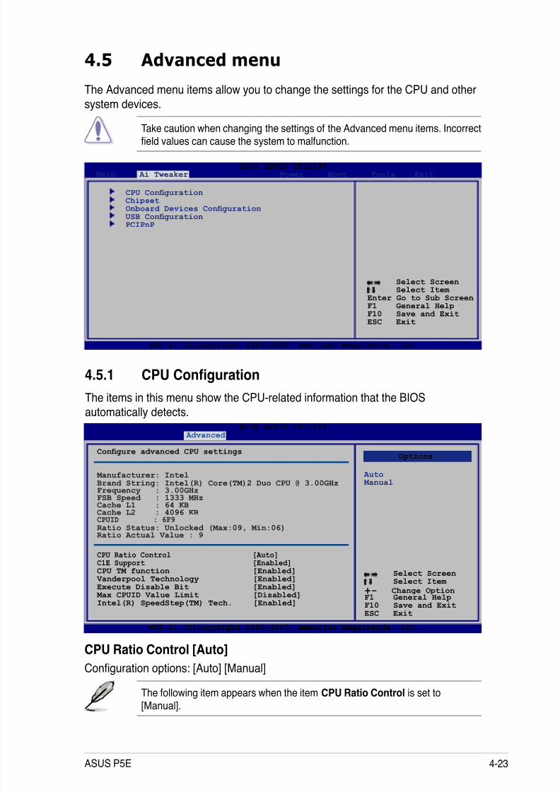
8/13/2019 Asus P5E Motherboard User Guide
http://slidepdf.com/reader/full/asus-p5e-motherboard-user-guide 89/174
ASUS P5E 4-23
4.5 Advanced menu
The Advanced menu items allow you to change the settings for the CPU and other
system devices.
Take caution when changing the settings of the Advanced menu items. Incorrecteld values can cause the system to malfunction.
Select Screen Select Item
Enter Go to Sub ScreenF1 General HelpF10 Save and ExitESC Exit
v02.61 (C)Copyright 1985-2007, American Megatrends, Inc.
BIOS SETUP UTILITY Main Ai Tweaker Power Boot Tools Exit
CPU Conguration Chipset Onboard Devices Conguration USB Conguration PCIPnP
Select Screen Select Item
+- Change OptionF1 General HelpF10 Save and ExitESC Exit
v02.61 (C)Copyright 1985-2007, American Megatrends, Inc.
BIOS SETUP UTILITY Advanced
4.5.1 CPU Conguration
The items in this menu show the CPU-related information that the BIOSautomatically detects.
Congure advanced CPU settings
M anufacturer: Intel Brand String: Intel(R) Core(TM)2 Duo CPU @ 3.00GHz Frequency : 3.00GHz FSB Speed : 1333 MHz Cache L1 : 64 KB Cache L2 : 4096 KB CPUID : 6F9
Ratio Status: Unlocked (Max:09, Min:06) Ratio Actual Value : 9
CPU Ratio Control [Auto] C1E Support [Enabled] CPU TM function [Enabled] Vanderpool Technology [Enabled] Execute Disable Bit [Enabled] Max CPUID Value Limit [Disabled] Intel(R) SpeedStep(TM) Tech. [Enabled]
Options
Auto Manual
CPU Ratio Control [Auto]
Conguration options: [Auto] [Manual]
The following item appears when the item CPU Ratio Control is set to
[Manual].
8/13/2019 Asus P5E Motherboard User Guide
http://slidepdf.com/reader/full/asus-p5e-motherboard-user-guide 90/174
4-24 Chapter 4: BIOS setup
Ratio CMOS Setting: [9] Allows you to set the ratio between the CPU Core Clock and the FSB
Frequency. Use <+> and <-> to adjust the value.
Conguration options: [ 6] [ 7] [ 8] [ 9]
The options vary depending on the CPU you install.
C1E Support [Enabled]
Allows you to enable or disable C1E Support.
Conguration options: [Disabled] [Enabled]
CPU TM function [Enabled]
Conguration options: [Disabled] [Enabled]
Vanderpool Technology [Enabled]
Conguration options: [Disabled] [Enabled]
Execute Disable Bit [Enabled]Allows you to enable or disable the No-Execution Page Protection Technology.
Setting this item to [Disabled] forces the XD feature ag to always return to zero(0). Conguration options: [Disabled] [Enabled]
Max CPUID Value Limit [Disabled]
Setting this item to [Enabled] allows legacy operating systems to boot even without
support for CPUs with extended CPUID functions.
Conguration options: [Disabled] [Enabled]
The following item appears only when you set the CPU Ratio Control item to[Auto].
Intel(R) SpeedStep (TM) Tech. [Enabled]
Conguration options: [Disabled] [Enabled]
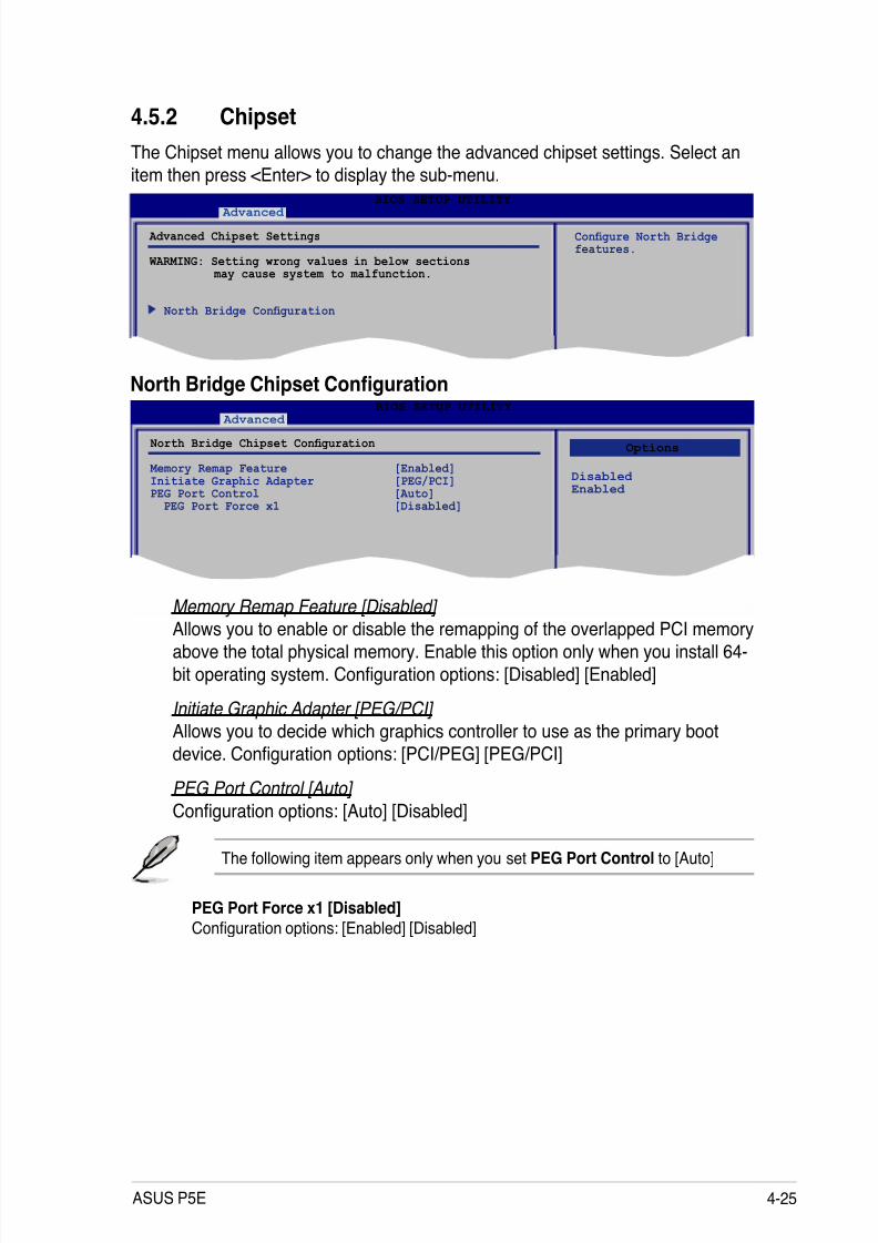
8/13/2019 Asus P5E Motherboard User Guide
http://slidepdf.com/reader/full/asus-p5e-motherboard-user-guide 91/174
ASUS P5E 4-25
BIOS SETUP UTILITY Advanced
4.5.2 Chipset
The Chipset menu allows you to change the advanced chipset settings. Select an
item then press <Enter> to display the sub-menu.
Advanced Chipset Settings
WARMING: Setting wrong values in below sections may cause system to malfunction.
North Bridge Conguration
Congure North Bridgefeatures.
BIOS SETUP UTILITY Advanced
North Bridge Chipset Conguration
Memory Remap Feature [Enabled] Initiate Graphic Adapter [PEG/PCI] PEG Port Control [Auto] PEG Port Force x1 [Disabled]
North Bridge Chipset Conguration
Memory Remap Feature [Disabled]
Allows you to enable or disable the remapping of the overlapped PCI memoryabove the total physical memory. Enable this option only when you install 64-
bit operating system. Conguration options: [Disabled] [Enabled]
Initiate Graphic Adapter [PEG/PCI] Allows you to decide which graphics controller to use as the primary boot
device. Conguration options: [PCI/PEG] [PEG/PCI]
PEG Port Control [Auto]
Conguration options: [Auto] [Disabled]
Options
Disabled Enabled
The following item appears only when you set PEG Port Control to [Auto]
PEG Port Force x1 [Disabled]Conguration options: [Enabled] [Disabled]

8/13/2019 Asus P5E Motherboard User Guide
http://slidepdf.com/reader/full/asus-p5e-motherboard-user-guide 92/174
4-26 Chapter 4: BIOS setup
4.5.3 Onboard Device Conguration
Select Screen Select Item
+- Change OptionF1 General HelpF10 Save and ExitESC Exit
v02.61 (C)Copyright 1985-2007, American Megatrends, Inc.
BIOS SETUP UTILITY Advanced
Onboard Device Conguration
High Denition Audio [Enabled] Front Panel Type [HD Audio] J-Micron PATA Controller [Enabled] Marvell GigaBit LAN [Enabled]
LAN Boot ROM [Disabled] VIA 1394 [Enabled]
Enable or DisableHigh Denition AudioController
High Denition Audio [Enabled]
Allows you to enable or disable the High Denition Audio Controller. Conguration options: [Enabled] [Disabled]
Front Panel Support Type [HD Audio]
Allows you to set the front panel audio connector (AAFP) mode to legacy
AC’97 or high-denition audio depending on the audio standard that the frontpanel audio module supports. Conguration options: [AC97] [HD Audio]
J-Micron PATA Controller [Enabled]
Conguration options: [Enabled] [Disabled]
MarvelI GigaBit LAN [Enabled]
Conguration options: [Enabled] [Disabled]
LAN Boot ROM [Disabled]
Conguration options: [Disabled] [Enabled]
VIA 1394 [Enabled]
Conguration options: [Enabled] [Disabled]

8/13/2019 Asus P5E Motherboard User Guide
http://slidepdf.com/reader/full/asus-p5e-motherboard-user-guide 93/174
ASUS P5E 4-27
4.5.4 USB Conguration
The items in this menu allows you to change the USB-related features. Select an
item then press <Enter> to display the conguration options.
The USB Devices Enabled item shows the auto-detected values. If no USBdevice is detected, the item shows None.
USB Functions [Enabled]
Allows you to enable or disable the USB Host Controllers.Conguration options: [Disabled] [Enabled]
The following items appear only when you set USB Functions to [Enabled].
USB 2.0 Controller [Enabled]
Allows you to enable or disable the USB 2.0 controller.
Conguration options: [Enabled] [Disabled]
USB 2.0 Controller Mode [HiSpeed]Allows you to set the USB 2.0 controller mode to HiSpeed (480 Mbps) or
FullSpeed (12 Mbps). Conguration options: [FullSpeed] [HiSpeed]
The USB 2.0 Controller Mode item appears only when you enable the USB2.0 Controller.
BIOS EHCI Hand-off [Enabled]
Allows you to enable the support for operating systems without an EHCI hand-off
feature. Conguration options: [Disabled] [Enabled]
Port 64/60 Emulation [Disabled]
Allows you to enable or disable the I/O port 60h/64h emulation support. This item
should be enabled for the complete USB keyboard legacy support for non-USBaware OSes. Conguration options: [Disabled] [Enabled]
Select Screen Select Item
+- Change OptionF1 General HelpF10 Save and ExitESC Exit
v02.61 (C)Copyright 1985-2007, American Megatrends, Inc.
BIOS SETUP UTILITY Advanced
USB Conguration
USB Devices Enabled: None
USB Functions [Enabled]USB 2.0 Controller [Enabled]USB 2.0 Controller Mode [HiSpeed]BIOS EHCI Hand-off [Enabled]Port 64/60 Emulation [Disabled]Legacy USB Support [Auto]
Options
Disabled Enabled
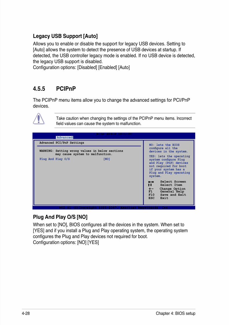
8/13/2019 Asus P5E Motherboard User Guide
http://slidepdf.com/reader/full/asus-p5e-motherboard-user-guide 94/174
4-28 Chapter 4: BIOS setup
4.5.5 PCIPnP
The PCIPnP menu items allow you to change the advanced settings for PCI/PnP
devices.
Take caution when changing the settings of the PCIPnP menu items. Incorrecteld values can cause the system to malfunction.
Plug And Play O/S [NO]When set to [NO], BIOS congures all the devices in the system. When set to[YES] and if you install a Plug and Play operating system, the operating system
congures the Plug and Play devices not required for boot.
Conguration options: [NO] [YES]
Select Screen Select Item
+- Change OptionF1 General HelpF10 Save and ExitESC Exit
v02.61 (C)Copyright 1985-2007, American Megatrends, Inc.
BIOS SETUP UTILITY Advanced
Advanced PCI/PnP Settings
WARNING: Setting wrong values in below sections may cause system to malfunction.
Plug And Play O/S [NO]
NO: lets the BIOScongure all thedevices in the system.
YES: lets the operatingsystem congure Plug
and Play (PnP) devicesnot required for bootif your system has aPlug and Play operatingsystem.
Legacy USB Support [Auto]
Allows you to enable or disable the support for legacy USB devices. Setting to
[Auto] allows the system to detect the presence of USB devices at startup. If
detected, the USB controller legacy mode is enabled. If no USB device is detected,the legacy USB support is disabled.
Conguration options: [Disabled] [Enabled] [Auto]
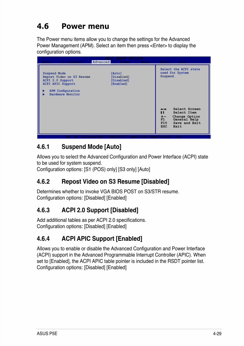
8/13/2019 Asus P5E Motherboard User Guide
http://slidepdf.com/reader/full/asus-p5e-motherboard-user-guide 95/174
ASUS P5E 4-29
4.6 Power menu
The Power menu items allow you to change the settings for the Advanced
Power Management (APM). Select an item then press <Enter> to display the
conguration options.
4.6.1 Suspend Mode [Auto]
Allows you to select the Advanced Conguration and Power Interface (ACPI) stateto be used for system suspend.
Conguration options: [S1 (POS) only] [S3 only] [Auto]
4.6.2 Repost Video on S3 Resume [Disabled]
Determines whether to invoke VGA BIOS POST on S3/STR resume.
Conguration options: [Disabled] [Enabled]
4.6.3 ACPI 2.0 Support [Disabled]
Add additional tables as per ACPI 2.0 specications.
Conguration options: [Disabled] [Enabled]
4.6.4 ACPI APIC Support [Enabled]
Allows you to enable or disable the Advanced Conguration and Power Interface(ACPI) support in the Advanced Programmable Interrupt Controller (APIC). When
set to [Enabled], the ACPI APIC table pointer is included in the RSDT pointer list.
Conguration options: [Disabled] [Enabled]
Select Screen Select Item
+- Change OptionF1 General HelpF10 Save and ExitESC Exit
v02.61 (C)Copyright 1985-2007, American Megatrends, Inc.
BIOS SETUP UTILITY Main Ai Tweaker Advanced Power Boot Tools Exit
Suspend Mode [Auto]Repost Video on S3 Resume [Disabled] ACPI 2.0 Support [Disabled] ACPI APIC Support [Enabled]
APM Conguration Hardware Monitor
Select the ACPI stateused for System Suspend.

8/13/2019 Asus P5E Motherboard User Guide
http://slidepdf.com/reader/full/asus-p5e-motherboard-user-guide 96/174
4-30 Chapter 4: BIOS setup
4.6.5 APM Conguration
Restore On AC Power Loss [Power Off]
When set to [Power Off], the system goes into off state after an AC power loss.When set to [Power On], the system goes on after an AC power loss. When set to
[Last State], the system goes into either off or on state, whatever the system state
was before the AC power loss.
Conguration options: [Power Off] [Power On] [Last State]
Power On By RTC Alarm [Disabled]
Allows you to enable or disable RTC to generate a wake event. When this itemis set to [Enabled], the items RTC Alarm Date/ RTC Alarm Hour/ RTC AlarmMinute/ RTC Alarm Second will become user-congurable with set values.Conguration options: [Disabled] [Enabled]
Power On By PCI Devices [Disabled]
Allows you to enable or disable the PME to wake up from S5 by PCI devices.
Conguration options: [Disabled] [Enabled]
Power On By PCIE Devices [Disabled]
Allows you to enable or disable the PCIE devices to generate a wake event.
Conguration options: [Disabled] [Enabled]
Power On By PS/2 Keyboard [Disabled]
Allows you to disable the Power On by PS/2 keyboard function or set specic keyson the PS/2 keyboard to turn on the system. This feature requires an ATX power
supply that provides at least 1A on the +5VSB lead.Conguration options: [Disabled] [Space Bar] [Ctrl-Esc] [Power Key]
Select Screen Select Item
+- Change OptionF1 General HelpF10 Save and ExitESC Exit
v02.61 (C)Copyright 1985-2007, American Megatrends, Inc.
BIOS SETUP UTILITY Power
APM Conguration
Restore on AC Power Loss [Power Off]Power On By RTC Alarm [Disabled]Power On By PCI Devices [Disabled]Power On By PCIE Devices [Disabled]Power On By PS/2 Keyboard [Disabled]
<Enter> to select
whether or not torestart the systemafter AC power loss.
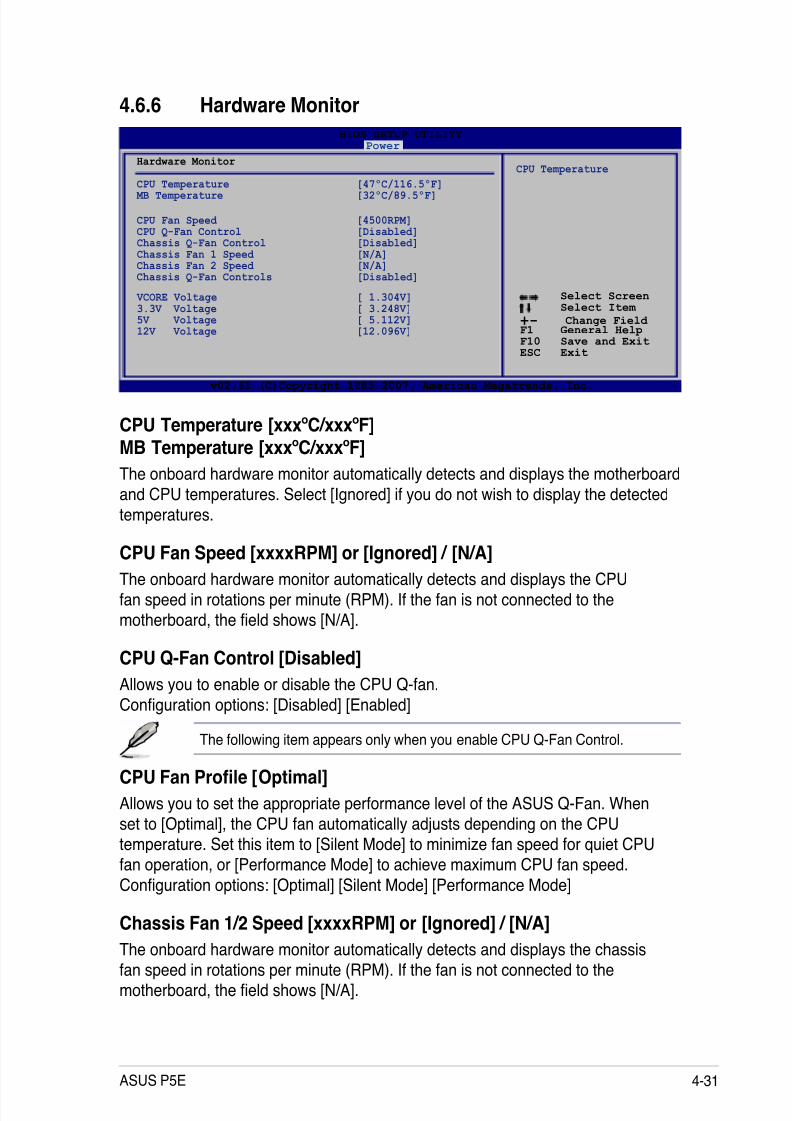
8/13/2019 Asus P5E Motherboard User Guide
http://slidepdf.com/reader/full/asus-p5e-motherboard-user-guide 97/174
ASUS P5E 4-31
4.6.6 Hardware Monitor
Select Screen Select Item
+- Change Field F1 General HelpF10 Save and ExitESC Exit
v02.61 (C)Copyright 1985-2007, American Megatrends, Inc.
BIOS SETUP UTILITY Power
Hardware Monitor
CPU Temperature [47ºC/116.5ºF] MB Temperature [32ºC/89.5ºF]
CPU Fan Speed [4500RPM]CPU Q-Fan Control [Disabled] Chassis Q-Fan Control [Disabled] Chassis Fan 1 Speed [N/A] Chassis Fan 2 Speed [N/A]Chassis Q-Fan Controls [Disabled]
VCORE Voltage [ 1.304V]3.3V Voltage [ 3.248V]5V Voltage [ 5.112V]12V Voltage [12.096V]
CPU Temperature
CPU Temperature [xxxºC/xxxºF]MB Temperature [xxxºC/xxxºF]
The onboard hardware monitor automatically detects and displays the motherboard
and CPU temperatures. Select [Ignored] if you do not wish to display the detected
temperatures.
CPU Fan Speed [xxxxRPM] or [Ignored] / [N/A]The onboard hardware monitor automatically detects and displays the CPU
fan speed in rotations per minute (RPM). If the fan is not connected to the
motherboard, the eld shows [N/A].
CPU Q-Fan Control [Disabled]
Allows you to enable or disable the CPU Q-fan.
Conguration options: [Disabled] [Enabled]
The following item appears only when you enable CPU Q-Fan Control.
CPU Fan Prole [Optimal]
Allows you to set the appropriate performance level of the ASUS Q-Fan. When
set to [Optimal], the CPU fan automatically adjusts depending on the CPU
temperature. Set this item to [Silent Mode] to minimize fan speed for quiet CPUfan operation, or [Performance Mode] to achieve maximum CPU fan speed.
Conguration options: [Optimal] [Silent Mode] [Performance Mode]
Chassis Fan 1/2 Speed [xxxxRPM] or [Ignored] / [N/A]
The onboard hardware monitor automatically detects and displays the chassis
fan speed in rotations per minute (RPM). If the fan is not connected to the
motherboard, the eld shows [N/A].

8/13/2019 Asus P5E Motherboard User Guide
http://slidepdf.com/reader/full/asus-p5e-motherboard-user-guide 98/174
4-32 Chapter 4: BIOS setup
Chassis Q-Fan Controls [Disabled]
Allows you to enable or disable the Chassis Q-fan.
Conguration options: [Disabled] [Enabled]
The following items appear only when you enable Chassis Q-Fan Control.
Chassis Fan Ratio [Auto]
Allows you to select a fan speed ratio in the low CPU temperature.
Conguration options [Auto] [90%] [80%] [70%] [60%]
A very low fan speed ratio may cause fan speed drop and trigger the hardwaremonitor warning message.
Chassis Target Temperature [37°C]
Chassis fan speed will auto-adjust to reach this target temperature.
Conguration options: [28°C] [31°C] [34°C] [37°C] [40°C] [43°C] [46°C]
VCORE Voltage, 3.3V Voltage, 5V Voltage, 12V Voltage
The onboard hardware monitor automatically detects the voltage output through
the onboard voltage regulators. Select [Ignored] if you do not want to detect this
item.

8/13/2019 Asus P5E Motherboard User Guide
http://slidepdf.com/reader/full/asus-p5e-motherboard-user-guide 99/174
ASUS P5E 4-33
4.7 Boot menu
The Boot menu items allow you to change the system boot options. Select an item
then press <Enter> to display the sub-menu.
Select Screen Select Item
Enter Go to Sub ScreenF1 General HelpF10 Save and ExitESC Exit
v02.61 (C)Copyright 1985-2007, American Megatrends, Inc.
BIOS SETUP UTILITY
Main Ai Tweaker Advanced Power Boot Tools Exit
Boot Device Priority
Boot Settings Conguration Security
Species the BootDevice Boot Prioritysequence.
A virtual oppy diskdrive (Floppy Drive B: ) may appear when youset the DVD-ROM drive as the rst bootdevice.
4.7.1 Boot Device Priority
1st ~ xxth Boot Device [xxx Drive]
These items specify the boot device priority sequence from the available devices.
The number of device items that appears on the screen depends on the number of
devices installed in the system. Conguration options: [1st FLOPPY DRIVE] [HardDrive] [ATAPI DVD-ROM] [Disabled]
Select Screen Select Item
+- Change OptionF1 General HelpF10 Save and ExitESC Exit
v02.61 (C)Copyright 1985-2007, American Megatrends, Inc.
BIOS SETUP UTILITY Boot
Boot Device Priority
1st Boot Device [1st FLOPPY DRIVE]2nd Boot Device [Hard Drive]3rd Boot Device [ATAPI DVD-ROM]
Species the bootsequence from the
availabe devices.
A device enclosedin parenthesis has been disabled in thecorresponding menu.
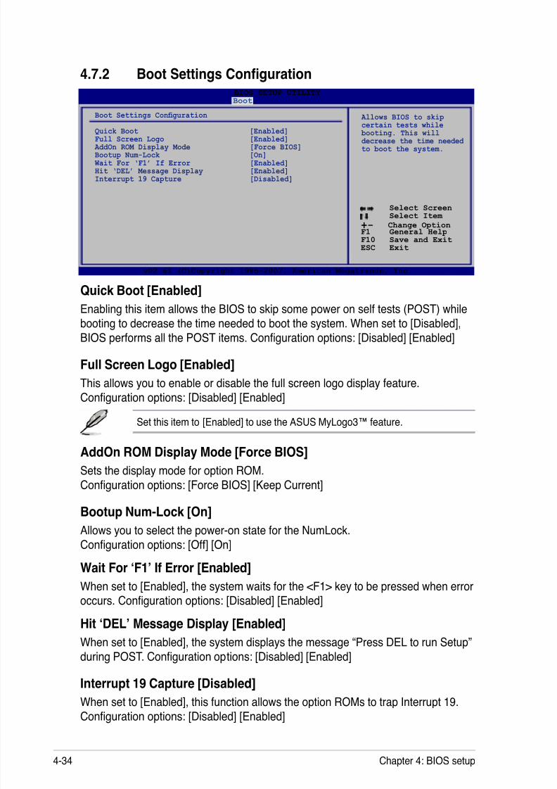
8/13/2019 Asus P5E Motherboard User Guide
http://slidepdf.com/reader/full/asus-p5e-motherboard-user-guide 100/174
4-34 Chapter 4: BIOS setup
4.7.2 Boot Settings Conguration
Quick Boot [Enabled]
Enabling this item allows the BIOS to skip some power on self tests (POST) while
booting to decrease the time needed to boot the system. When set to [Disabled],
BIOS performs all the POST items. Conguration options: [Disabled] [Enabled]
Full Screen Logo [Enabled]
This allows you to enable or disable the full screen logo display feature.
Conguration options: [Disabled] [Enabled]
Set this item to [Enabled] to use the ASUS MyLogo3™ feature.
AddOn ROM Display Mode [Force BIOS]
Sets the display mode for option ROM.
Conguration options: [Force BIOS] [Keep Current]
Bootup Num-Lock [On]
Allows you to select the power-on state for the NumLock.Conguration options: [Off] [On]
Wait For ‘F1’ If Error [Enabled]
When set to [Enabled], the system waits for the <F1> key to be pressed when error
occurs. Conguration options: [Disabled] [Enabled]
Hit ‘DEL’ Message Display [Enabled]
When set to [Enabled], the system displays the message “Press DEL to run Setup”
during POST. Conguration options: [Disabled] [Enabled]
Interrupt 19 Capture [Disabled]
When set to [Enabled], this function allows the option ROMs to trap Interrupt 19.
Conguration options: [Disabled] [Enabled]
Select Screen Select Item
+- Change OptionF1 General HelpF10 Save and ExitESC Exit
v02.61 (C)Copyright 1985-2007, American Megatrends, Inc.
BIOS SETUP UTILITY Boot
Boot Settings Conguration
Quick Boot [Enabled]Full Screen Logo [Enabled] AddOn ROM Display Mode [Force BIOS]Bootup Num-Lock [On] Wait For ‘F1’ If Error [Enabled]Hit ‘DEL’ Message Display [Enabled]Interrupt 19 Capture [Disabled]
Allows BIOS to skipcertain tests while
booting. This willdecrease the time neededto boot the system.
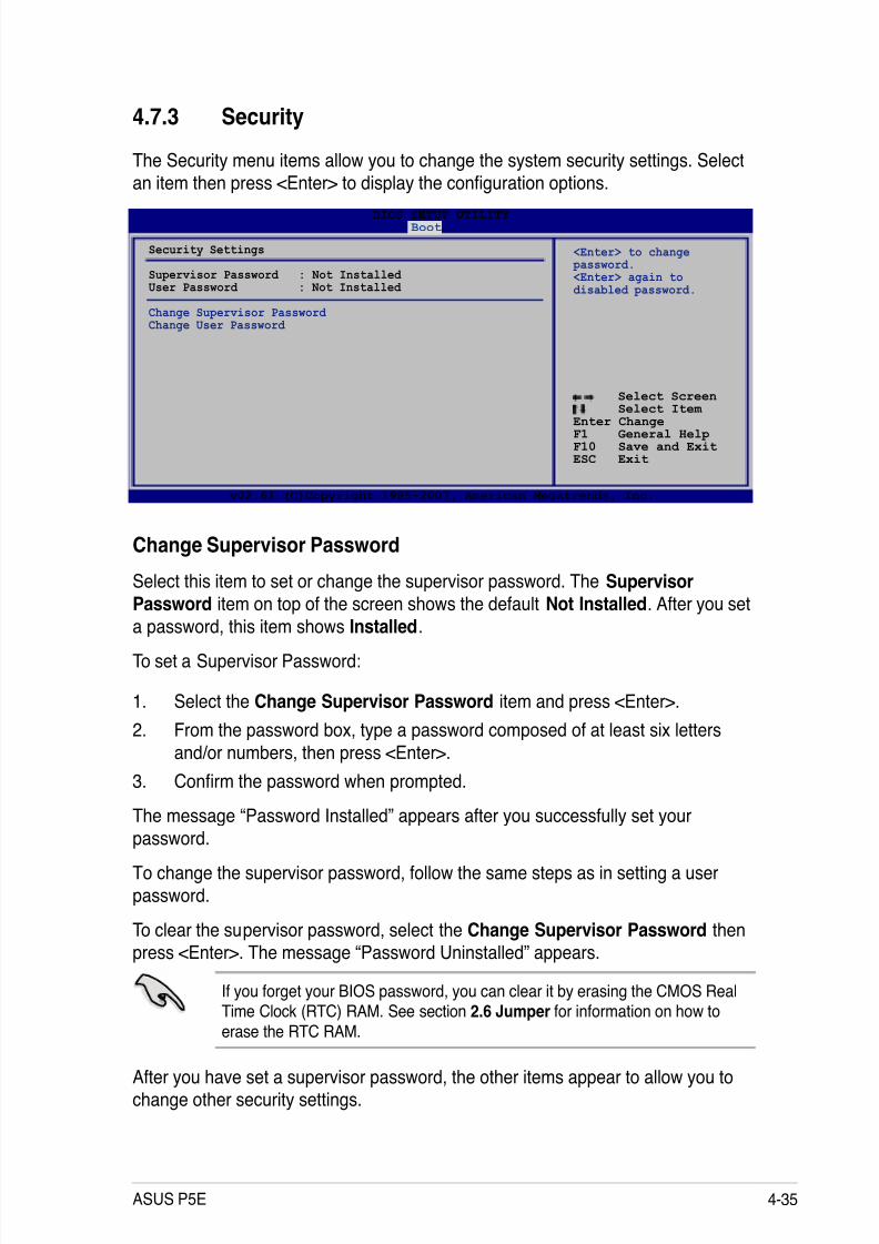
8/13/2019 Asus P5E Motherboard User Guide
http://slidepdf.com/reader/full/asus-p5e-motherboard-user-guide 101/174
ASUS P5E 4-35
4.7.3 Security
The Security menu items allow you to change the system security settings. Select
an item then press <Enter> to display the conguration options.
Change Supervisor Password
Select this item to set or change the supervisor password. The SupervisorPassword item on top of the screen shows the default Not Installed. After you set
a password, this item shows Installed.
To set a Supervisor Password:
1. Select the Change Supervisor Password item and press <Enter>.
2. From the password box, type a password composed of at least six letters
and/or numbers, then press <Enter>.
3. Conrm the password when prompted.
The message “Password Installed” appears after you successfully set your
password.
To change the supervisor password, follow the same steps as in setting a user
password.
To clear the supervisor password, select the Change Supervisor Password thenpress <Enter>. The message “Password Uninstalled” appears.
If you forget your BIOS password, you can clear it by erasing the CMOS RealTime Clock (RTC) RAM. See section 2.6 Jumper for information on how to
erase the RTC RAM.
After you have set a supervisor password, the other items appear to allow you tochange other security settings.
Select Screen
Select Item Enter ChangeF1 General HelpF10 Save and ExitESC Exit
v02.61 (C)Copyright 1985-2007, American Megatrends, Inc.
BIOS SETUP UTILITY Boot
Security Settings
Supervisor Password : Not Installed User Password : Not Installed
Change Supervisor Password Change User Password
<Enter> to change password. <Enter> again todisabled password.

8/13/2019 Asus P5E Motherboard User Guide
http://slidepdf.com/reader/full/asus-p5e-motherboard-user-guide 102/174
4-36 Chapter 4: BIOS setup
User Access Level [Full Access]
This item allows you to select the access restriction to the Setup items.
Conguration options: [No Access] [View Only] [Limited] [Full Access]
[No Access] prevents user access to the Setup utility.
[View Only] allows access but does not allow change to any eld.
[Limited] allows changes only to selected elds, such as Date and Time.
[Full Access] allows viewing and changing all the elds in the Setup utility.
Change User Password
Select this item to set or change the user password. The User Password item on
top of the screen shows the default Not Installed. After you set a password, this
item shows Installed.
To set a User Password:
1. Select the Change User Password item and press <Enter>.
2. On the password box that appears, type a password composed of at least sixletters and/or numbers, then press <Enter>.
3. Conrm the password when prompted.
The message “Password Installed” appears after you set your passwordsuccessfully.
To change the user password, follow the same steps as in setting a user password.
Clear User Password
Select this item to clear the user password.Password Check [Setup]
When set to [Setup], BIOS checks for user password when accessing the Setuputility. When set to [Always], BIOS checks for user password both when accessing
Setup and booting the system. Conguration options: [Setup] [Always]
Select Screen Select Item
Enter ChangeF1 General HelpF10 Save and ExitESC Exit
v02.61 (C)Copyright 1985-2007, American Megatrends, Inc.
BIOS SETUP UTILITY Boot
Security Settings
Supervisor Password : Installed User Password : Installed
Change Supervisor Password User Access Level [Full Access]Change User Password Clear User Password Password Check [Setup]
<Enter> to change password. <Enter> again todisabled password.
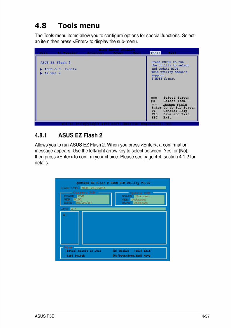
8/13/2019 Asus P5E Motherboard User Guide
http://slidepdf.com/reader/full/asus-p5e-motherboard-user-guide 103/174
ASUS P5E 4-37
4.8 Tools menu
The Tools menu items allow you to congure options for special functions. Selectan item then press <Enter> to display the sub-menu.
Select Screen Select Item
+- Change Field Enter Go to Sub ScreenF1 General HelpF10 Save and ExitESC Exit
v02.61 (C)Copyright 1985-2007, American Megatrends, Inc.
BIOS SETUP UTILITY
Main Ai Tweaker Advanced Power Boot Tools Exit
ASUS EZ Flash 2
ASUS O.C. Prole
Ai Net 2
Press ENTER to runthe utility to selectand update BIOS.This utility doesn'tsupport : 1.NTFS format
4.8.1 ASUS EZ Flash 2
Allows you to run ASUS EZ Flash 2. When you press <Enter>, a conrmationmessage appears. Use the left/right arrow key to select between [Yes] or [No],
then press <Enter> to conrm your choice. Please see page 4-4, section 4.1.2 for
details.
ASUSTek EZ Flash 2 BIOS ROM Utility V3.06
Current ROM Update ROM
A:
Note [Enter] Select or Load [B] Backup [ESC] Exit
[Tab] Switch [Up/Down/Home/End] Move
FLASH TYPE: MXIC 25L1605A
PATH: A:\
BOARD: P5E
VER: 0102DATE: 08/24/07
BOARD: Unknown VER: UnknownDATE: Unknown

8/13/2019 Asus P5E Motherboard User Guide
http://slidepdf.com/reader/full/asus-p5e-motherboard-user-guide 104/174
4-38 Chapter 4: BIOS setup
Select Screen Select Item
Enter Go to Sub ScreenF1 General Help
F10 Save and ExitESC Exit
v02.61 (C)Copyright 1985-2007, American Megatrends, Inc.
BIOS SETUP UTILITY Tools
O.C. PROFILE Conguration
O.C. Prole 1 Status : Not Installed O.C. Prole 2 Status : Not Installed
Save to Prole 1 Load from Prole 1
Save to Prole 2 Load from Prole 2
Start O.C. Prole
Save to Prole 1
4.8.2 ASUS O.C. Prole
This item allows you to store or load multiple BIOS settings.
Save to Proe 1/2
Allows you to save the current BIOS le to the BIOS Flash. Press <Enter> to savethe le.
Load from Prole 1/2
Allows you to load the previous BIOS settings saved in the BIOS Flash. Press
<Enter> to load the le.
Start O.C. Prole
Allows you to run the utility to save and load CMOS. Press <Enter> to run the
utility.
Current CMOS Restore CMOS
A:
Note [Enter] Select or Load [B] Backup [ESC] Exit
[Tab] Switch [Up/Down/Home/End] Move
PATH: A:\
BOARD: P5E
VER: 0102
DATE: 08/24/07
BOARD: Unknown VER: Unknown
DATE: Unknown
• This function can support devices such as a USB ash disk or a oppy
disk with FAT 32/16 format and single partition only.• DO NOT shut down or reset the system while updating the BIOS to
prevent the system boot failure!
ASUSTek O.C. Prole Utility V1.06
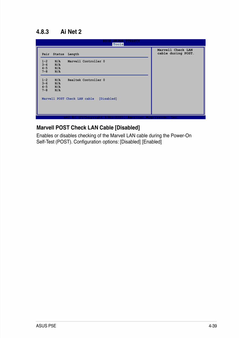
8/13/2019 Asus P5E Motherboard User Guide
http://slidepdf.com/reader/full/asus-p5e-motherboard-user-guide 105/174
ASUS P5E 4-39
ASUSTek O.C. Prole Utility V1.06
4.8.3 Ai Net 2
Marvell POST Check LAN Cable [Disabled]
Enables or disables checking of the Marvell LAN cable during the Power-On
Self-Test (POST). Conguration options: [Disabled] [Enabled]
v02.61 (C)Copyright 1985-2007, American Megatrends, Inc.
Pair Status Length 1-2 N/A Marvell Controller 0 3-6 N/A 4-5 N/A 7-8 N/A
1-2 N/A Realtek Controller 0 3-6 N/A 4-5 N/A 7-8 N/A
Marvell POST Check LAN cable [Disabled]
Marvell Check LANcable during POST.
BIOS SETUP UTILITY Tools
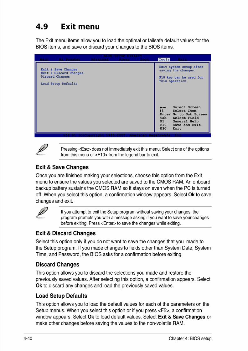
8/13/2019 Asus P5E Motherboard User Guide
http://slidepdf.com/reader/full/asus-p5e-motherboard-user-guide 106/174
4-40 Chapter 4: BIOS setup
4.9 Exit menu
Pressing <Esc> does not immediately exit this menu. Select one of the optionsfrom this menu or <F10> from the legend bar to exit.
The Exit menu items allow you to load the optimal or failsafe default values for the
BIOS items, and save or discard your changes to the BIOS items.
Select Screen Select Item
Enter Go to Sub Screen
Tab Select Field F1 General HelpF10 Save and ExitESC Exit
v02.61 (C)Copyright 1985-2007, American Megatrends, Inc.
BIOS SETUP UTILITY Main Ai Tweaker Advanced Power Boot Tools Exit
Exit & Save ChangesExit & Discard ChangesDiscard Changes
Load Setup Defaults
Exit system setup aftersaving the changes.
F10 key can be used forthis operation.
Exit & Save Changes
Once you are nished making your selections, choose this option from the Exitmenu to ensure the values you selected are saved to the CMOS RAM. An onboardbackup battery sustains the CMOS RAM so it stays on even when the PC is turned
off. When you select this option, a conrmation window appears. Select Ok to save
changes and exit.
If you attempt to exit the Setup program without saving your changes, theprogram prompts you with a message asking if you want to save your changesbefore exiting. Press <Enter> to save the changes while exiting.
Exit & Discard ChangesSelect this option only if you do not want to save the changes that you made to
the Setup program. If you made changes to elds other than System Date, SystemTime, and Password, the BIOS asks for a conrmation before exiting.
Discard Changes
This option allows you to discard the selections you made and restore the
previously saved values. After selecting this option, a conrmation appears. SelectOk to discard any changes and load the previously saved values.
Load Setup Defaults
This option allows you to load the default values for each of the parameters on the
Setup menus. When you select this option or if you press <F5>, a conrmationwindow appears. Select Ok to load default values. Select Exit & Save Changes or
make other changes before saving the values to the non-volatile RAM.

8/13/2019 Asus P5E Motherboard User Guide
http://slidepdf.com/reader/full/asus-p5e-motherboard-user-guide 107/174
5 Softwaresupport
This chapter describes the contents of
the support DVD that comes with themotherboard package.
8/13/2019 Asus P5E Motherboard User Guide
http://slidepdf.com/reader/full/asus-p5e-motherboard-user-guide 108/174
ASUS P5E
Chapter summary 5 5.1 Installing an operating system ................................................... 5-1
5.2 Support DVD information ............................................................ 5-1
5.3 Software information ................................................................... 5-9
5.4 RAID congurations .................................................................. 5-35
5.5 Creating a RAID driver disk ....................................................... 5-44
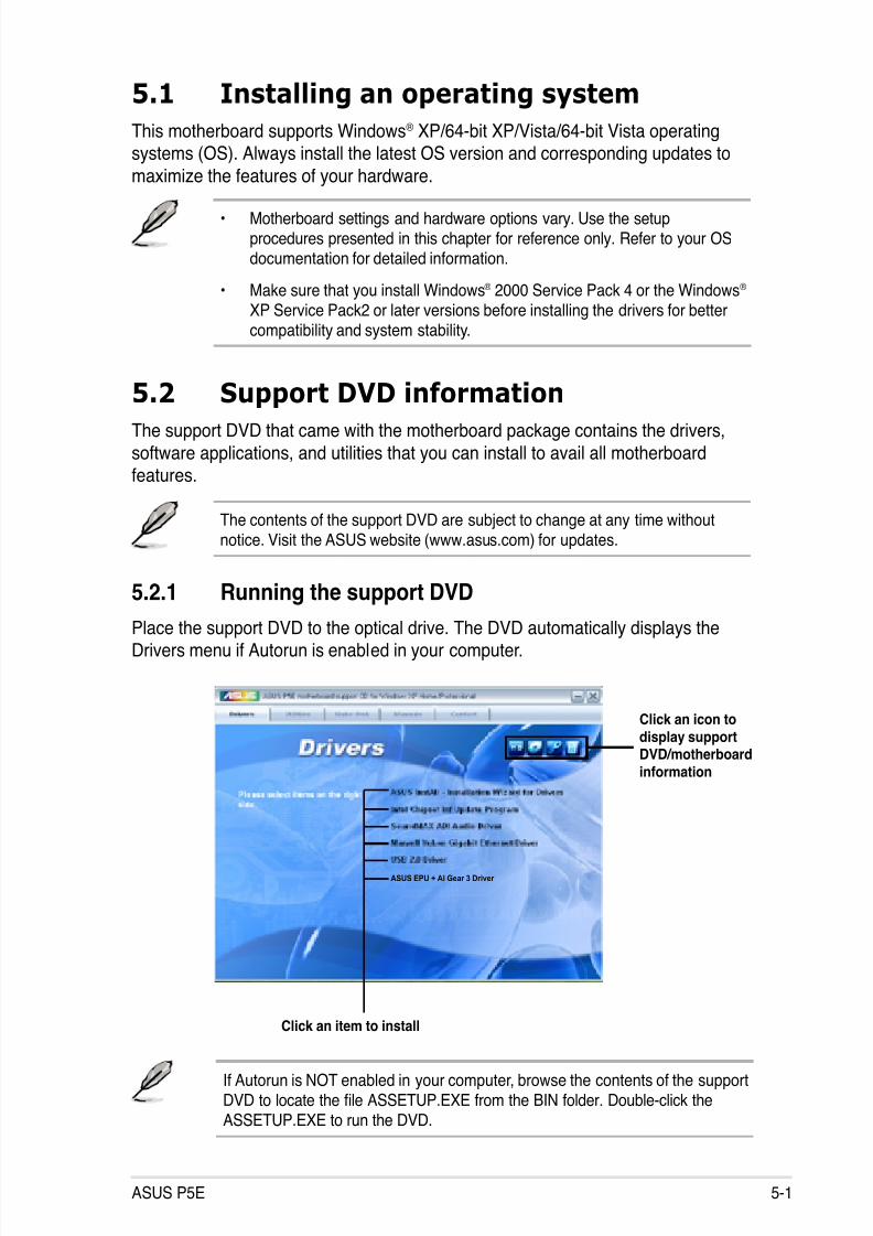
8/13/2019 Asus P5E Motherboard User Guide
http://slidepdf.com/reader/full/asus-p5e-motherboard-user-guide 109/174
ASUS P5E 5-1
If Autorun is NOT enabled in your computer, browse the contents of the supportDVD to locate the le ASSETUP.EXE from the BIN folder. Double-click the
ASSETUP.EXE to run the DVD.
5.1 Installing an operating system
This motherboard supports Windows® XP/64-bit XP/Vista/64-bit Vista operatingsystems (OS). Always install the latest OS version and corresponding updates to
maximize the features of your hardware.
5.2 Support DVD information
The support DVD that came with the motherboard package contains the drivers,
software applications, and utilities that you can install to avail all motherboardfeatures.
5.2.1 Running the support DVD
Place the support DVD to the optical drive. The DVD automatically displays theDrivers menu if Autorun is enabled in your computer.
• Motherboard settings and hardware options vary. Use the setupprocedures presented in this chapter for reference only. Refer to your OSdocumentation for detailed information.
• Make sure that you install Windows® 2000 Service Pack 4 or the Windows® XP Service Pack2 or later versions before installing the drivers for bettercompatibility and system stability.
The contents of the support DVD are subject to change at any time withoutnotice. Visit the ASUS website (www.asus.com) for updates.
Click an icon todisplay supportDVD/motherboardinformation
Click an item to install
ASUS EPU + AI Gear 3 Driver
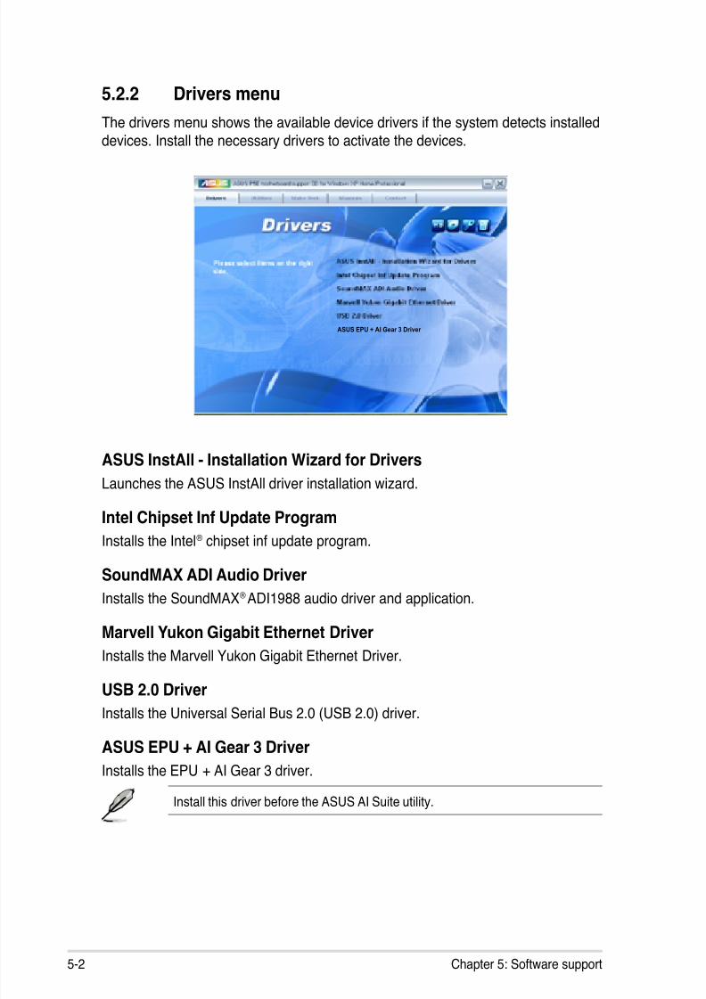
8/13/2019 Asus P5E Motherboard User Guide
http://slidepdf.com/reader/full/asus-p5e-motherboard-user-guide 110/174
5-2 Chapter 5: Software support
5.2.2 Drivers menu
The drivers menu shows the available device drivers if the system detects installed
devices. Install the necessary drivers to activate the devices.
ASUS InstAll - Installation Wizard for Drivers
Launches the ASUS InstAll driver installation wizard.
Intel Chipset Inf Update Program
Installs the Intel® chipset inf update program.
SoundMAX ADI Audio Driver
Installs the SoundMAX® ADI1988 audio driver and application.
Marvell Yukon Gigabit Ethernet Driver
Installs the Marvell Yukon Gigabit Ethernet Driver.
USB 2.0 Driver
Installs the Universal Serial Bus 2.0 (USB 2.0) driver.
ASUS EPU + AI Gear 3 Driver
Installs the EPU + AI Gear 3 driver.
Install this driver before the ASUS AI Suite utility.
ASUS EPU + AI Gear 3 Driver

8/13/2019 Asus P5E Motherboard User Guide
http://slidepdf.com/reader/full/asus-p5e-motherboard-user-guide 111/174
ASUS P5E 5-3
5.2.3 Utilities menu
The Utilities menu shows the applications and other software that the motherboard
supports.
ASUS InstAll-Installation Wizard for Utilities
Installs all of the utilities through the Installation Wizard.
Marvell Yukon VCT Application
Installs the Marvell® Yukon Virtual Cable Tester™ (VCT) application that diagnoses
and reports LAN cable faults and shorts using the Time Domain Reectometry(TDR) technology.
ASUS PC Probe II
This smart utility monitors the fan speed, CPU temperature, and system voltages,and alerts you of any detected problems. This utility helps you keep your computer
in healthy operating condition.
ASUS AI Suite
Installs the ASUS AI Suite.
ASUS Update
The ASUS Update utility allows you to update the motherboard BIOS in Windows ®
environment. This utility requires an Internet connection either through a network
or an Internet Service Provider (ISP).
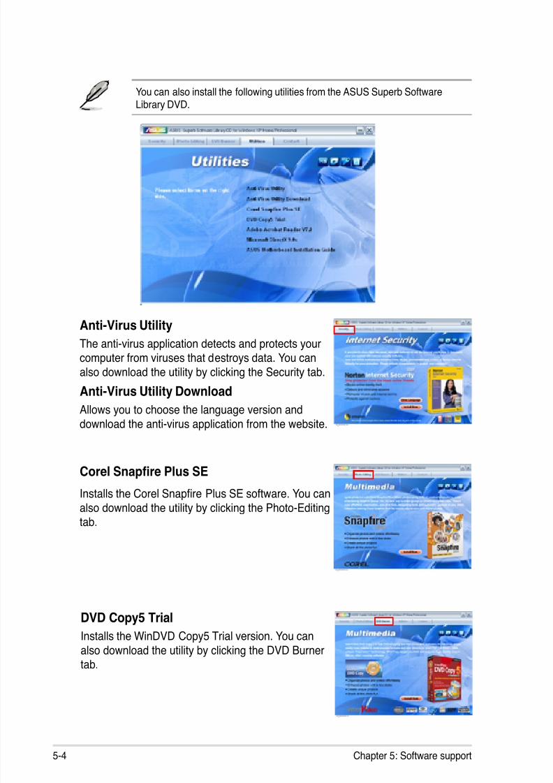
8/13/2019 Asus P5E Motherboard User Guide
http://slidepdf.com/reader/full/asus-p5e-motherboard-user-guide 112/174
5-4 Chapter 5: Software support
You can also install the following utilities from the ASUS Superb SoftwareLibrary DVD.
Anti-Virus Utility
The anti-virus application detects and protects yourcomputer from viruses that destroys data. You can
also download the utility by clicking the Security tab.
Anti-Virus Utility DownloadAllows you to choose the language version and
download the anti-virus application from the website.
Corel Snapre Plus SE
Installs the Corel Snapre Plus SE software. You canalso download the utility by clicking the Photo-Editing
tab.
DVD Copy5 Trial
Installs the WinDVD Copy5 Trial version. You can
also download the utility by clicking the DVD Burnertab.

8/13/2019 Asus P5E Motherboard User Guide
http://slidepdf.com/reader/full/asus-p5e-motherboard-user-guide 113/174
ASUS P5E 5-5
5.2.4 Make Disk menu
The Make Disk menu contains items to create the Intel ICH9R or JMicron® JMB368RAID/AHCI driver disk.
Intel ICH9 32/64 bit RAID/AHCI Driver
Allows you to create an ICH9R 32/64bit RAID/AHCI driver disk.
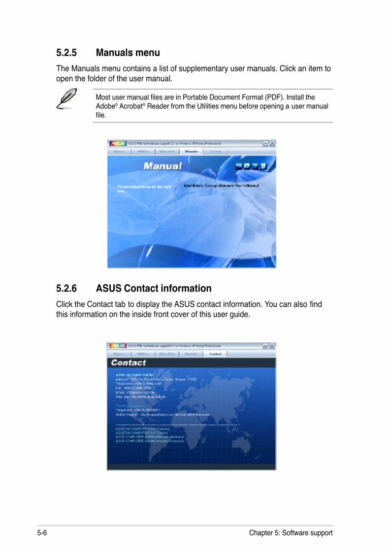
8/13/2019 Asus P5E Motherboard User Guide
http://slidepdf.com/reader/full/asus-p5e-motherboard-user-guide 114/174
5-6 Chapter 5: Software support
5.2.5 Manuals menu
The Manuals menu contains a list of supplementary user manuals. Click an item to
open the folder of the user manual.
Most user manual les are in Portable Document Format (PDF). Install the
Adobe® Acrobat® Reader from the Utilities menu before opening a user manualle.
5.2.6 ASUS Contact information
Click the Contact tab to display the ASUS contact information. You can also ndthis information on the inside front cover of this user guide.
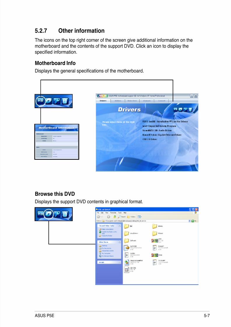
8/13/2019 Asus P5E Motherboard User Guide
http://slidepdf.com/reader/full/asus-p5e-motherboard-user-guide 115/174
ASUS P5E 5-7
5.2.7 Other information
The icons on the top right corner of the screen give additional information on the
motherboard and the contents of the support DVD. Click an icon to display the
specied information.
Motherboard Info
Displays the general specications of the motherboard.
Browse this DVD
Displays the support DVD contents in graphical format.
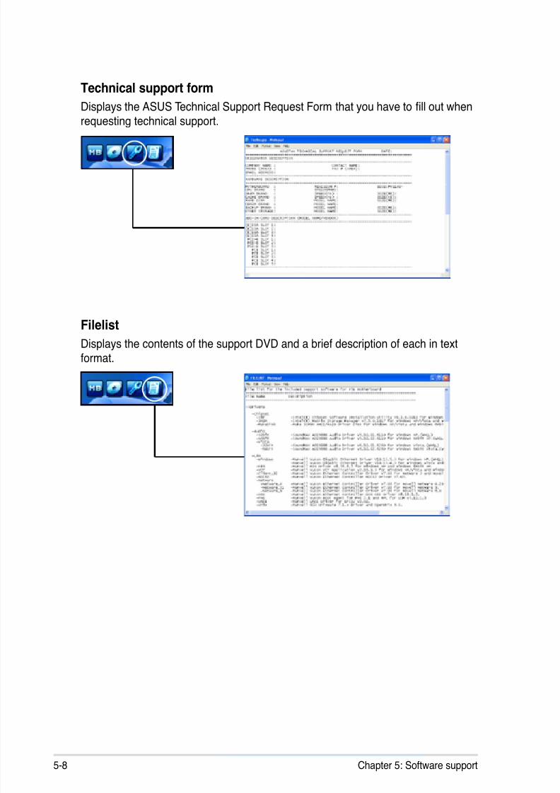
8/13/2019 Asus P5E Motherboard User Guide
http://slidepdf.com/reader/full/asus-p5e-motherboard-user-guide 116/174
5-8 Chapter 5: Software support
Filelist
Displays the contents of the support DVD and a brief description of each in textformat.
Technical support form
Displays the ASUS Technical Support Request Form that you have to ll out whenrequesting technical support.
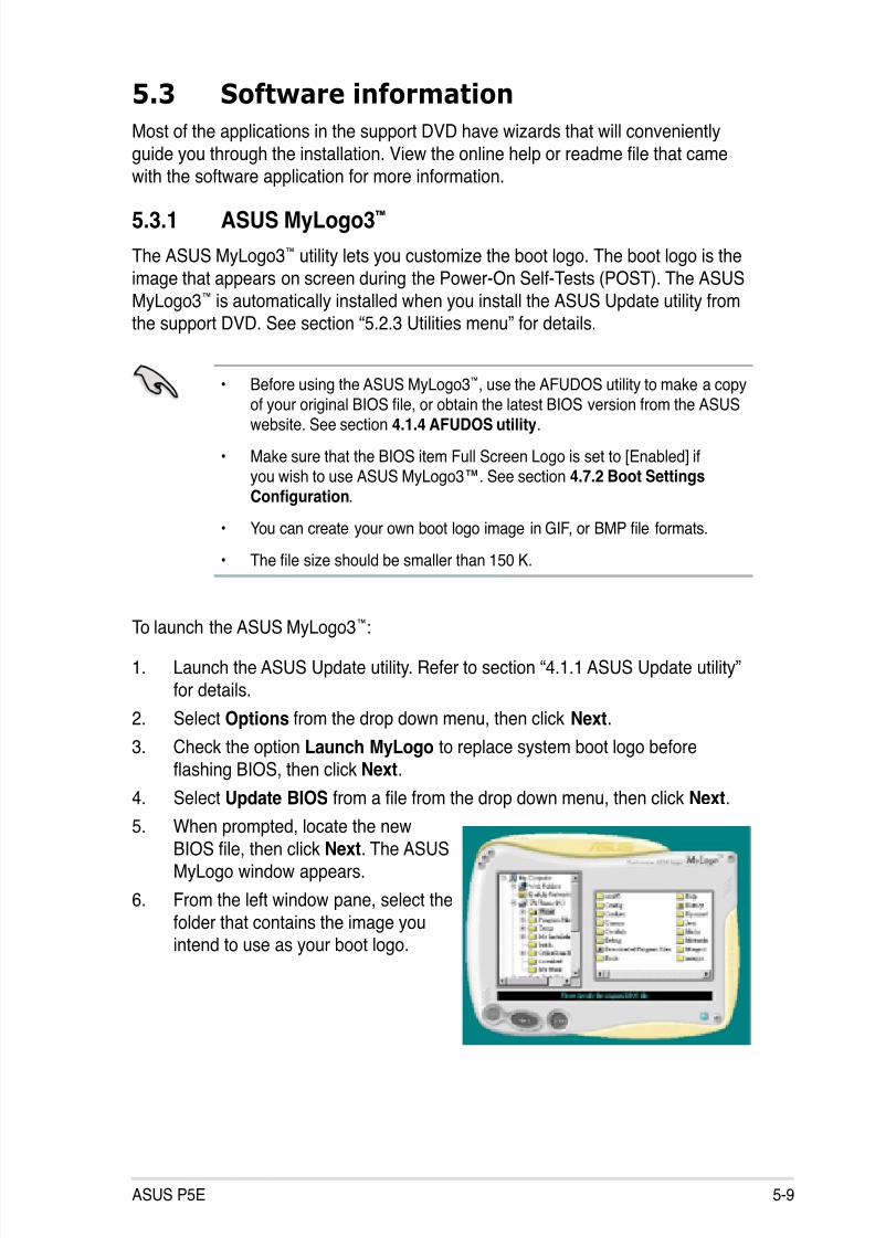
8/13/2019 Asus P5E Motherboard User Guide
http://slidepdf.com/reader/full/asus-p5e-motherboard-user-guide 117/174
ASUS P5E 5-9
5.3 Software information
Most of the applications in the support DVD have wizards that will convenientlyguide you through the installation. View the online help or readme le that camewith the software application for more information.
5.3.1 ASUS MyLogo3™
The ASUS MyLogo3™ utility lets you customize the boot logo. The boot logo is theimage that appears on screen during the Power-On Self-Tests (POST). The ASUS
MyLogo3™ is automatically installed when you install the ASUS Update utility fromthe support DVD. See section “5.2.3 Utilities menu” for details.
To launch the ASUS MyLogo3™:
1. Launch the ASUS Update utility. Refer to section “4.1.1 ASUS Update utility”
for details.
2. Select Options from the drop down menu, then click Next.
3. Check the option Launch MyLogo to replace system boot logo before
ashing BIOS, then click Next.
4. Select Update BIOS from a le from the drop down menu, then click Next.
5. When prompted, locate the newBIOS le, then click Next. The ASUS
MyLogo window appears.
6. From the left window pane, select the
folder that contains the image youintend to use as your boot logo.
• Before using the ASUS MyLogo3™, use the AFUDOS utility to make a copy
of your original BIOS le, or obtain the latest BIOS version from the ASUSwebsite. See section 4.1.4 AFUDOS utility.
• Make sure that the BIOS item Full Screen Logo is set to [Enabled] ifyou wish to use ASUS MyLogo3™. See section 4.7.2 Boot Settings
Conguration.
• You can create your own boot logo image in GIF, or BMP le formats.
• The le size should be smaller than 150 K.
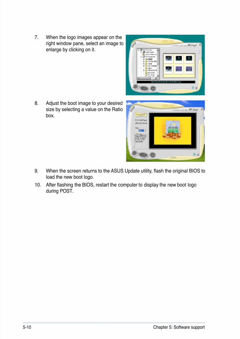
8/13/2019 Asus P5E Motherboard User Guide
http://slidepdf.com/reader/full/asus-p5e-motherboard-user-guide 118/174
5-10 Chapter 5: Software support
9. When the screen returns to the ASUS Update utility, ash the original BIOS toload the new boot logo.
10. After ashing the BIOS, restart the computer to display the new boot logoduring POST.
8. Adjust the boot image to your desired
size by selecting a value on the Ratiobox.
7. When the logo images appear on theright window pane, select an image to
enlarge by clicking on it.
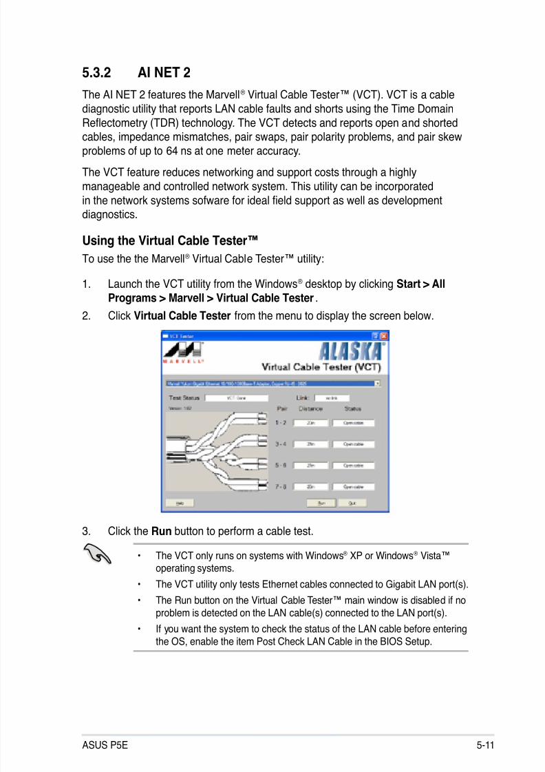
8/13/2019 Asus P5E Motherboard User Guide
http://slidepdf.com/reader/full/asus-p5e-motherboard-user-guide 119/174
ASUS P5E 5-11
3. Click the Run button to perform a cable test.
5.3.2 AI NET 2
The AI NET 2 features the Marvell® Virtual Cable Tester™ (VCT). VCT is a cable
diagnostic utility that reports LAN cable faults and shorts using the Time Domain
Reectometry (TDR) technology. The VCT detects and reports open and shortedcables, impedance mismatches, pair swaps, pair polarity problems, and pair skew
problems of up to 64 ns at one meter accuracy.
The VCT feature reduces networking and support costs through a highly
manageable and controlled network system. This utility can be incorporated
in the network systems sofware for ideal eld support as well as developmentdiagnostics.
Using the Virtual Cable Tester™
To use the the Marvell® Virtual Cable Tester™ utility:
1. Launch the VCT utility from the Windows® desktop by clicking Start > AllPrograms > Marvell > Virtual Cable Tester.
2. Click Virtual Cable Tester from the menu to display the screen below.
• The VCT only runs on systems with Windows® XP or Windows® Vista™operating systems.
• The VCT utility only tests Ethernet cables connected to Gigabit LAN port(s).
• The Run button on the Virtual Cable Tester™ main window is disabled if no
problem is detected on the LAN cable(s) connected to the LAN port(s).
• If you want the system to check the status of the LAN cable before entering
the OS, enable the item Post Check LAN Cable in the BIOS Setup.

8/13/2019 Asus P5E Motherboard User Guide
http://slidepdf.com/reader/full/asus-p5e-motherboard-user-guide 120/174
5-12 Chapter 5: Software support
5.3.3 AI Audio 2 (SoundMAX® High Denition Audio utility)
The ADI AD1988B High Denition Audio CODEC provides 8-channel audiocapability through the SoundMAX® audio utility with AudioESP™ software to
deliver the ultimate audio experience on your PC. The software implements highquality audio synthesis/rendering, 3D sound positioning, and advanced voice-input
technologies.
Follow the installation wizard to install the ADI AD1988B Audio Driver from thesupport DVD that comes with the motherboard package to activate the
SoundMAX® audio utility.
If the SoundMAX® audio utility is correctly installed, you
will nd the SoundMAX®/ SoundMAX® BlackHawk iconon the taskbar.
You must use 4-channel, 6-channel or 8-channel speakers for this setup.
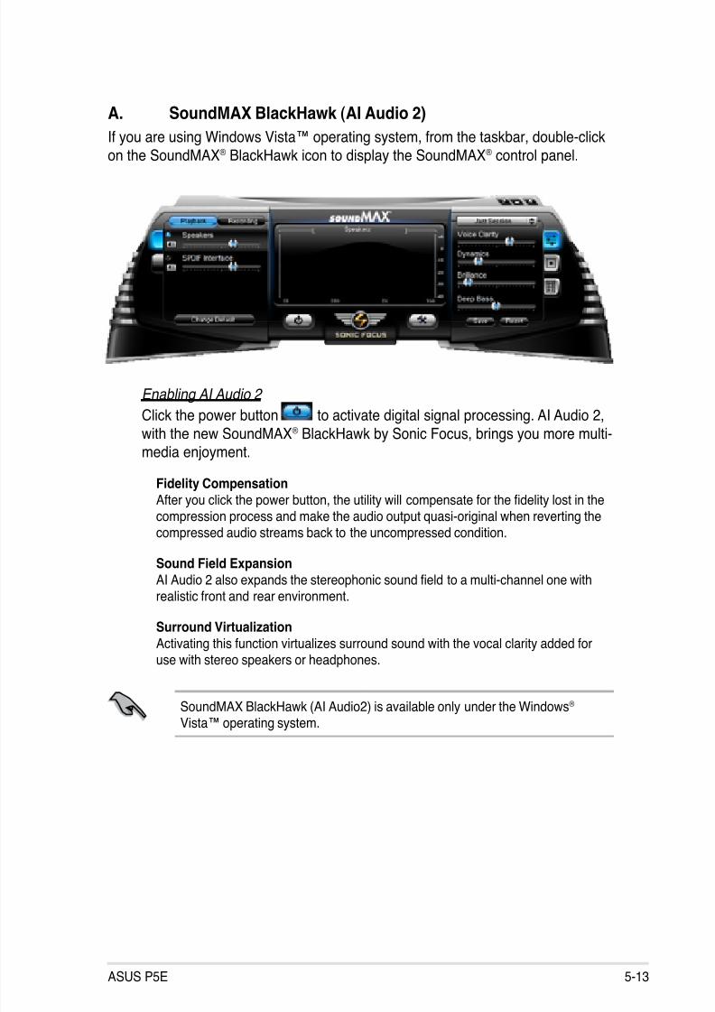
8/13/2019 Asus P5E Motherboard User Guide
http://slidepdf.com/reader/full/asus-p5e-motherboard-user-guide 121/174
ASUS P5E 5-13
A. SoundMAX BlackHawk (AI Audio 2)
If you are using Windows Vista™ operating system, from the taskbar, double-click
on the SoundMAX® BlackHawk icon to display the SoundMAX® control panel.
Enabling AI Audio 2
Click the power button to activate digital signal processing. AI Audio 2,
with the new SoundMAX® BlackHawk by Sonic Focus, brings you more multi-media enjoyment.
Fidelity Compensation
After you click the power button, the utility will compensate for the delity lost in thecompression process and make the audio output quasi-original when reverting thecompressed audio streams back to the uncompressed condition.
Sound Field ExpansionAI Audio 2 also expands the stereophonic sound eld to a multi-channel one with
realistic front and rear environment.
Surround VirtualizationActivating this function virtualizes surround sound with the vocal clarity added for
use with stereo speakers or headphones.
SoundMAX BlackHawk (AI Audio2) is available only under the Windows® Vista™ operating system.

8/13/2019 Asus P5E Motherboard User Guide
http://slidepdf.com/reader/full/asus-p5e-motherboard-user-guide 122/174
5-14 Chapter 5: Software support
Playback Settings
To congure the playback settings, click the Playback button on the control
panel. You can adjust the volume of the Speakers and SPDIF Interface ormute the audio.
Preset settings
Click and expand the drop-down menuto select your preferred Digital SignalProcessing (DSP) preset. Move the slidersto customize the values of Voice Clarity,Dynamics, Brilliance, and Deep Bass
of each preset. Click Save to save the
changes to the current preset. Or, clickReset to discard the changes and restorethe preset to the factory defaults.
Surround settings
Allows you to change the settings of thestereo speakers. Move the sliders tochange the listener position or adjust the
center channel volume. Press the TestSpeakers button to perform speaker test.
Port settings
Click this port settings tab to display the rear panel ports conguration for thespeakers or rear panel digital port conguration for the SPDIF interface.
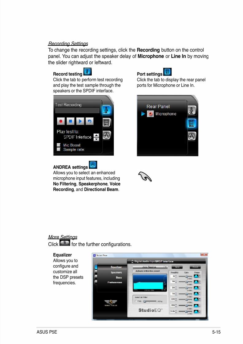
8/13/2019 Asus P5E Motherboard User Guide
http://slidepdf.com/reader/full/asus-p5e-motherboard-user-guide 123/174
ASUS P5E 5-15
More Settings
Click for the further congurations.
Equalizer
Allows you tocongure andcustomize all
the DSP presetsfrequencies.
Recording Settings
To change the recording settings, click the Recording button on the control
panel. You can adjust the speaker delay of Microphone or Line In by movingthe slider rightward or leftward.
Port settings
Click the tab to display the rear panelports for Microphone or Line In.
ANDREA settings
Allows you to select an enhancedmicrophone input features, includingNo Filtering, Speakerphone, VoiceRecording, and Directional Beam.
Record testing
Click the tab to perform test recordingand play the test sample through thespeakers or the SPDIF interface.
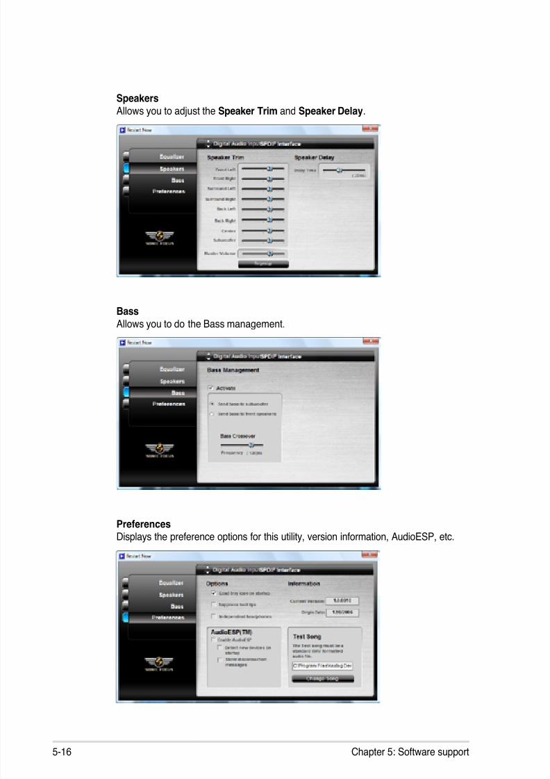
8/13/2019 Asus P5E Motherboard User Guide
http://slidepdf.com/reader/full/asus-p5e-motherboard-user-guide 124/174
5-16 Chapter 5: Software support
Speakers
Allows you to adjust the Speaker Trim and Speaker Delay.
Bass
Allows you to do the Bass management.
PreferencesDisplays the preference options for this utility, version information, AudioESP, etc.
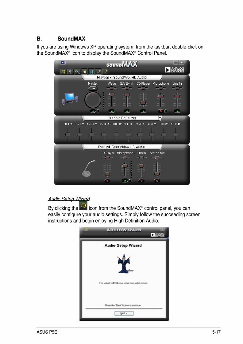
8/13/2019 Asus P5E Motherboard User Guide
http://slidepdf.com/reader/full/asus-p5e-motherboard-user-guide 125/174
ASUS P5E 5-17
B. SoundMAX
If you are using Windows XP operating system, from the taskbar, double-click onthe SoundMAX® icon to display the SoundMAX® Control Panel.
Audio Setup Wizard
By clicking the icon from the SoundMAX® control panel, you can
easily congure your audio settings. Simply follow the succeeding screeninstructions and begin enjoying High Denition Audio.

8/13/2019 Asus P5E Motherboard User Guide
http://slidepdf.com/reader/full/asus-p5e-motherboard-user-guide 126/174
5-18 Chapter 5: Software support
Jack configuration
This screen helps you congure
your computer’s audio ports,depending on the audio devicesyou have installed.
Adjust speaker volume
This screen helps you adjust
speaker volume. Click the Test button to hear the changes youhave made.
Adjust microphone volume
This screen helps you adjust microphone volume. You will be asked to read
pre-written text to allow the AudioWizard to adjust the volume as you speak.
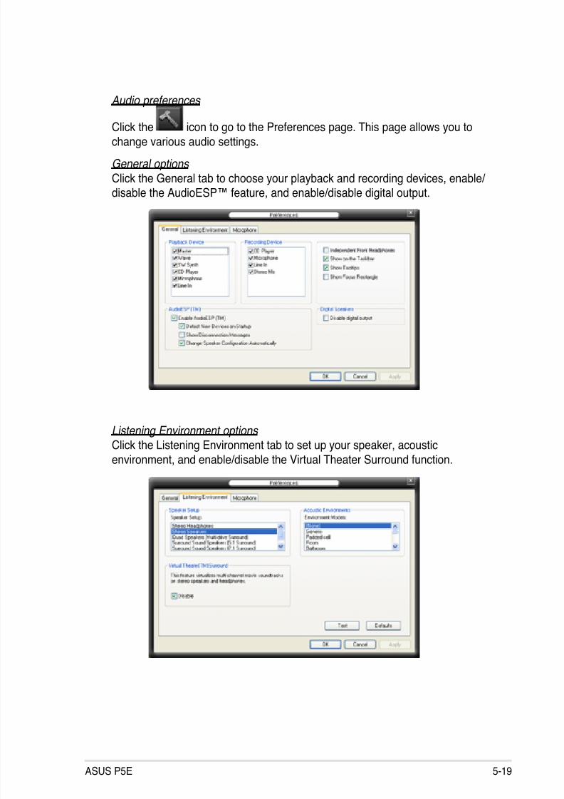
8/13/2019 Asus P5E Motherboard User Guide
http://slidepdf.com/reader/full/asus-p5e-motherboard-user-guide 127/174
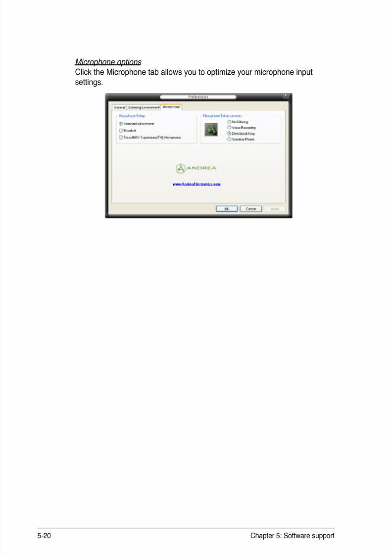
8/13/2019 Asus P5E Motherboard User Guide
http://slidepdf.com/reader/full/asus-p5e-motherboard-user-guide 128/174
5-20 Chapter 5: Software support
Microphone options
Click the Microphone tab allows you to optimize your microphone inputsettings.
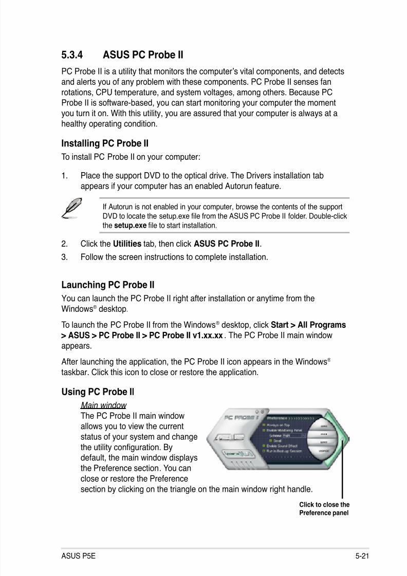
8/13/2019 Asus P5E Motherboard User Guide
http://slidepdf.com/reader/full/asus-p5e-motherboard-user-guide 129/174
ASUS P5E 5-21
5.3.4 ASUS PC Probe II
PC Probe II is a utility that monitors the computer’s vital components, and detectsand alerts you of any problem with these components. PC Probe II senses fan
rotations, CPU temperature, and system voltages, among others. Because PCProbe II is software-based, you can start monitoring your computer the moment
you turn it on. With this utility, you are assured that your computer is always at a
healthy operating condition.
Installing PC Probe II
To install PC Probe II on your computer:
1. Place the support DVD to the optical drive. The Drivers installation tab
appears if your computer has an enabled Autorun feature.
If Autorun is not enabled in your computer, browse the contents of the supportDVD to locate the setup.exe le from the ASUS PC Probe II folder. Double-click
the setup.exe le to start installation.
2. Click the Utilities tab, then click ASUS PC Probe II.
3. Follow the screen instructions to complete installation.
Launching PC Probe IIYou can launch the PC Probe II right after installation or anytime from the
Windows® desktop.
To launch the PC Probe II from the Windows® desktop, click Start > All Programs> ASUS > PC Probe II > PC Probe II v1.xx.xx. The PC Probe II main window
appears.
After launching the application, the PC Probe II icon appears in the Windows®
taskbar. Click this icon to close or restore the application.
Using PC Probe II
Main window
The PC Probe II main windowallows you to view the current
status of your system and change
the utility conguration. Bydefault, the main window displays
the Preference section. You can
close or restore the Preferencesection by clicking on the triangle on the main window right handle.
Click to close thePreference panel
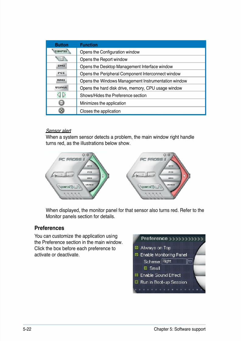
8/13/2019 Asus P5E Motherboard User Guide
http://slidepdf.com/reader/full/asus-p5e-motherboard-user-guide 130/174
5-22 Chapter 5: Software support
Button Function
Opens the Conguration window
Opens the Report window
Opens the Desktop Management Interface window
Opens the Peripheral Component Interconnect window
Opens the Windows Management Instrumentation window
Opens the hard disk drive, memory, CPU usage window
Shows/Hides the Preference section
Minimizes the application
Closes the application
Sensor alert
When a system sensor detects a problem, the main window right handleturns red, as the illustrations below show.
When displayed, the monitor panel for that sensor also turns red. Refer to theMonitor panels section for details.
PreferencesYou can customize the application usingthe Preference section in the main window.
Click the box before each preference to
activate or deactivate.

8/13/2019 Asus P5E Motherboard User Guide
http://slidepdf.com/reader/full/asus-p5e-motherboard-user-guide 131/174
ASUS P5E 5-23
Changing the monitor panels position
To change the position of the monitor panels in the desktop,
click the arrow down button of the Scheme options, then selectanother position from the list box. Click OK when nished.
Moving the monitor panels
All monitor panels move together using a magnetic effect. Ifyou want to detach a monitor panel from
the group, click the horseshoe magnet
icon. You can now move or reposition the
panel independently.
Hardware monitor panels
The hardware monitor panels display the current value of a system sensor such as
fan rotation, CPU temperature, and voltages.
The hardware monitor panels come in two display modes: hexagonal (large) andrectangular (small). When you check the Enable Monitoring Panel option from the
Preference section, the monitor panels appear on your computer’s desktop.
Large display
Small display
Click toincreasevalue
Click to
decreasevalue
Adjusting the sensor threshold valueYou can adjust the sensor threshold
value in the monitor panel by
clicking the or buttons. You canalso adjust the threshold values
using the Cong window.
You cannot adjust the sensorthreshold values in a small
monitoring panel.

8/13/2019 Asus P5E Motherboard User Guide
http://slidepdf.com/reader/full/asus-p5e-motherboard-user-guide 132/174
5-24 Chapter 5: Software support
Monitoring sensor alert The monitor panel turns red when a component value exceeds or is lower
than the threshold value. Refer to the illustrations below.
Large display
Small display
WMI browser
Click to display the
WMI (Windows Management
Instrumentation) browser. Thisbrowser displays various Windows®
management information. Click an
item from the left panel to display on
the right panel. Click the plus sign (+)before WMI Information to display the
available information.
You can enlarge or reduce the browser size by dragging the bottom right corner
of the browser.
DMI browserClick to display the DMI
(Desktop Management Interface)
browser. This browser displays various
desktop and system information.Click the plus sign (+) before DMI
Information to display the available
information.
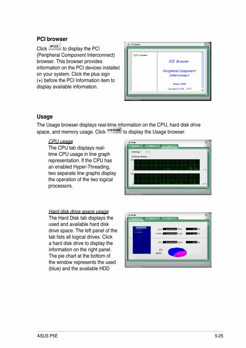
8/13/2019 Asus P5E Motherboard User Guide
http://slidepdf.com/reader/full/asus-p5e-motherboard-user-guide 133/174
ASUS P5E 5-25
PCI browser
Click to display the PCI
(Peripheral Component Interconnect)
browser. This browser provides
information on the PCI devices installedon your system. Click the plus sign
(+) before the PCI Information item to
display available information.
UsageThe Usage browser displays real-time information on the CPU, hard disk drive
space, and memory usage. Click to display the Usage browser.
CPU usage
The CPU tab displays real-time CPU usage in line graph
representation. If the CPU has
an enabled Hyper-Threading,
two separate line graphs displaythe operation of the two logical
processors.
Hard disk drive space usage
The Hard Disk tab displays theused and available hard disk
drive space. The left panel of thetab lists all logical drives. Click
a hard disk drive to display theinformation on the right panel.
The pie chart at the bottom of
the window represents the used(blue) and the available HDD
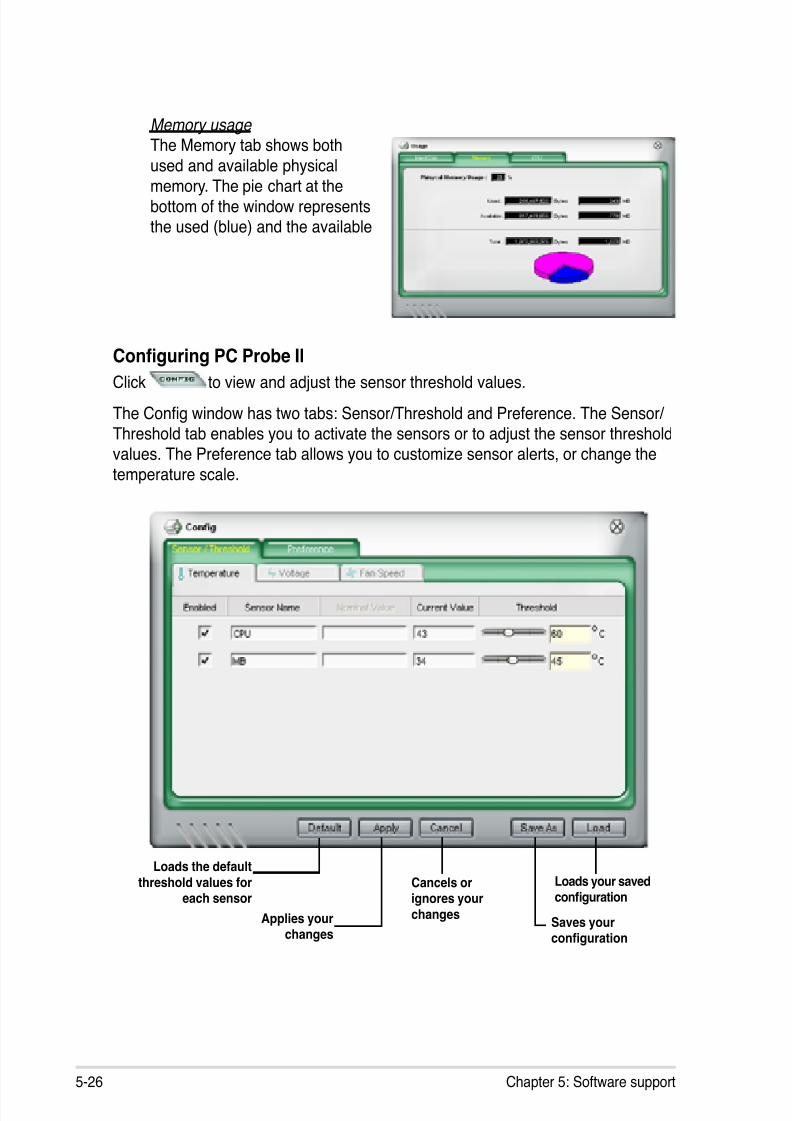
8/13/2019 Asus P5E Motherboard User Guide
http://slidepdf.com/reader/full/asus-p5e-motherboard-user-guide 134/174
5-26 Chapter 5: Software support
Memory usage The Memory tab shows both
used and available physical
memory. The pie chart at thebottom of the window representsthe used (blue) and the available
Conguring PC Probe II
Click to view and adjust the sensor threshold values.
The Cong window has two tabs: Sensor/Threshold and Preference. The Sensor/ Threshold tab enables you to activate the sensors or to adjust the sensor threshold
values. The Preference tab allows you to customize sensor alerts, or change thetemperature scale.
Loads the defaultthreshold values for
each sensor
Applies your
changes
Cancels orignores yourchanges
Loads your savedconguration
Saves your
conguration
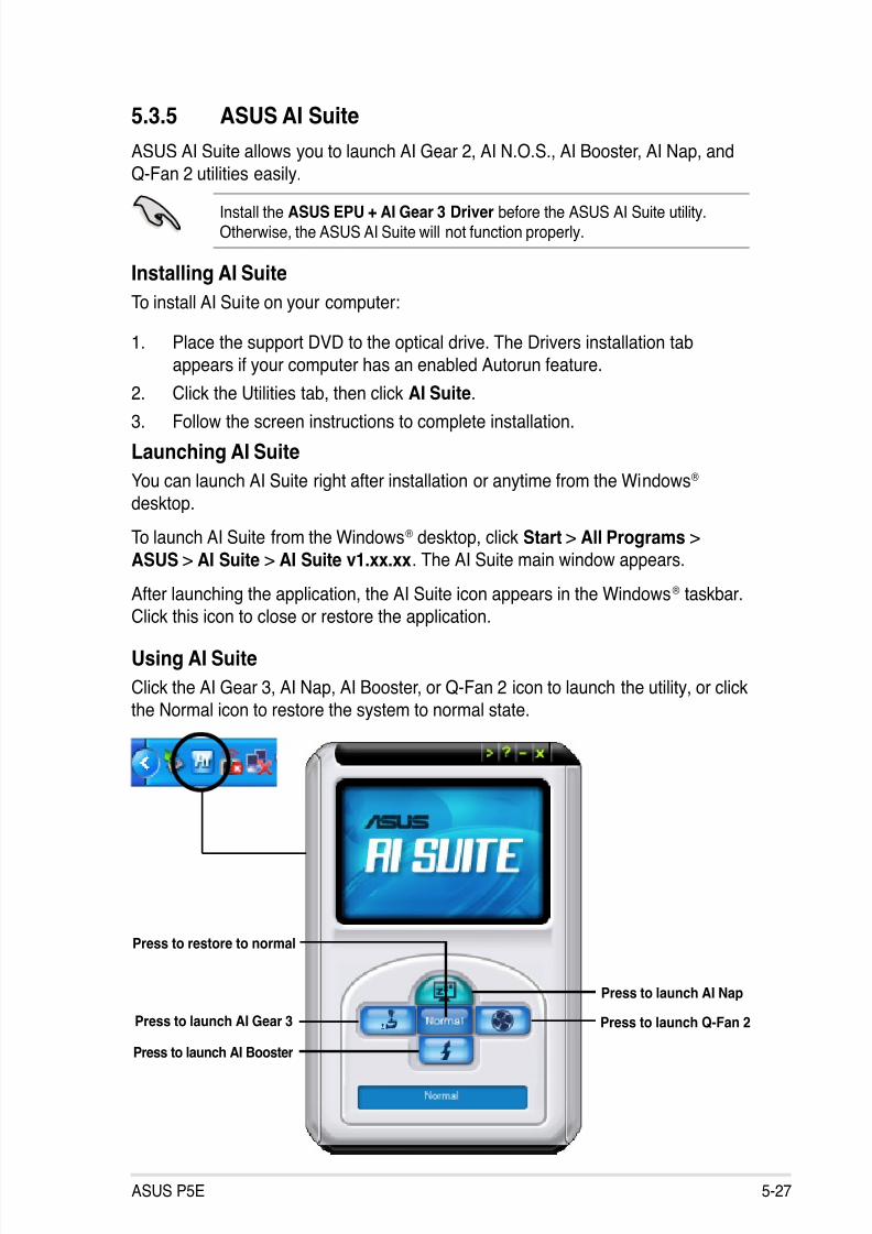
8/13/2019 Asus P5E Motherboard User Guide
http://slidepdf.com/reader/full/asus-p5e-motherboard-user-guide 135/174
ASUS P5E 5-27
5.3.5 ASUS AI Suite
ASUS AI Suite allows you to launch AI Gear 2, AI N.O.S., AI Booster, AI Nap, and
Q-Fan 2 utilities easily.
Install the ASUS EPU + AI Gear 3 Driver before the ASUS AI Suite utility.Otherwise, the ASUS AI Suite will not function properly.
Installing AI Suite
To install AI Suite on your computer:
1. Place the support DVD to the optical drive. The Drivers installation tab
appears if your computer has an enabled Autorun feature.
2. Click the Utilities tab, then click AI Suite.
3. Follow the screen instructions to complete installation.
Launching AI Suite
You can launch AI Suite right after installation or anytime from the Windows®
desktop.
To launch AI Suite from the Windows® desktop, click Start > All Programs > ASUS > AI Suite > AI Suite v1.xx.xx. The AI Suite main window appears.
After launching the application, the AI Suite icon appears in the Windows® taskbar.
Click this icon to close or restore the application.
Using AI Suite
Click the AI Gear 3, AI Nap, AI Booster, or Q-Fan 2 icon to launch the utility, or click
the Normal icon to restore the system to normal state.
Press to launch AI Gear 3
Press to launch AI Nap
Press to launch Q-Fan 2Press to launch AI Booster
Press to restore to normal
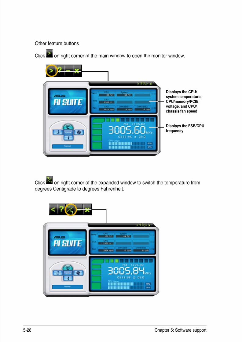
8/13/2019 Asus P5E Motherboard User Guide
http://slidepdf.com/reader/full/asus-p5e-motherboard-user-guide 136/174
5-28 Chapter 5: Software support
Other feature buttons
Click on right corner of the main window to open the monitor window.
Click on right corner of the expanded window to switch the temperature fromdegrees Centigrade to degrees Fahrenheit.
Displays the CPU/ system temperature,CPU/memory/PCIEvoltage, and CPU/ chassis fan speed
Displays the FSB/CPUfrequency
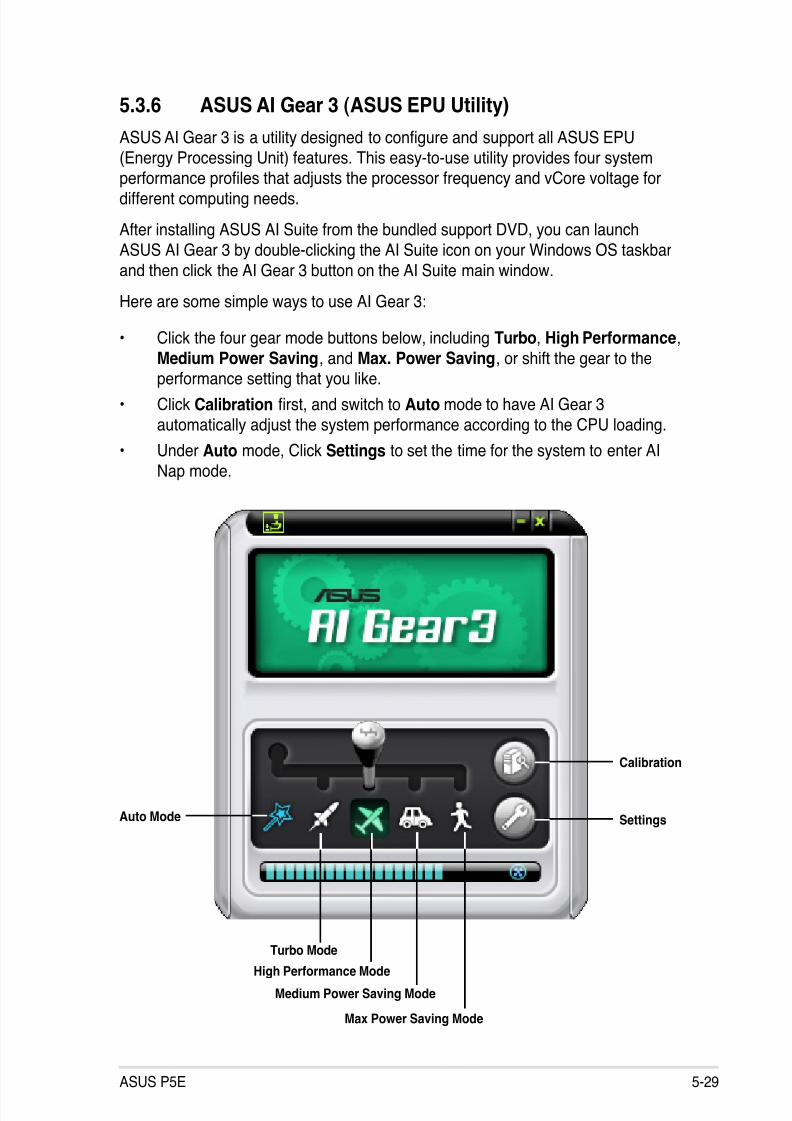
8/13/2019 Asus P5E Motherboard User Guide
http://slidepdf.com/reader/full/asus-p5e-motherboard-user-guide 137/174
ASUS P5E 5-29
Auto Mode
Calibration
Turbo Mode
High Performance Mode
Medium Power Saving Mode
Max Power Saving Mode
Settings
5.3.6 ASUS AI Gear 3 (ASUS EPU Utility)
ASUS AI Gear 3 is a utility designed to congure and support all ASUS EPU(Energy Processing Unit) features. This easy-to-use utility provides four system
performance proles that adjusts the processor frequency and vCore voltage fordifferent computing needs.
After installing ASUS AI Suite from the bundled support DVD, you can launch
ASUS AI Gear 3 by double-clicking the AI Suite icon on your Windows OS taskbar
and then click the AI Gear 3 button on the AI Suite main window.
Here are some simple ways to use AI Gear 3:
• Click the four gear mode buttons below, including Turbo, High Performance,
Medium Power Saving, and Max. Power Saving, or shift the gear to the
performance setting that you like.
• Click Calibration rst, and switch to Auto mode to have AI Gear 3
automatically adjust the system performance according to the CPU loading.
• Under Auto mode, Click Settings to set the time for the system to enter AI
Nap mode.
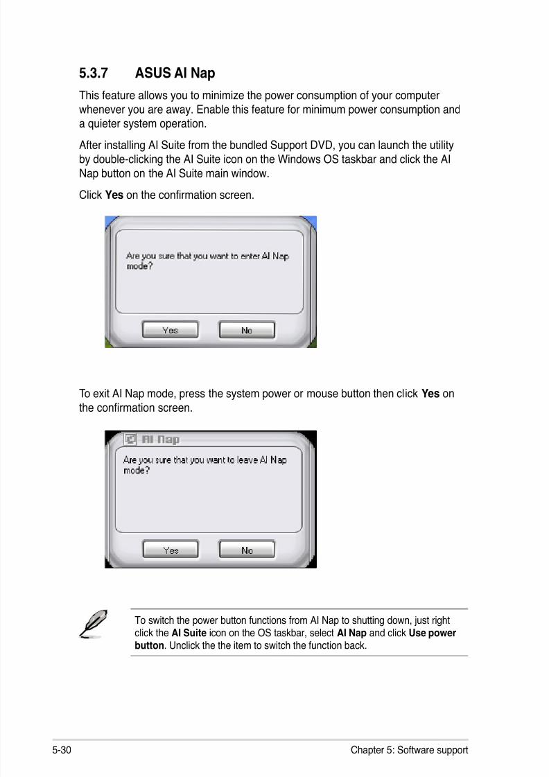
8/13/2019 Asus P5E Motherboard User Guide
http://slidepdf.com/reader/full/asus-p5e-motherboard-user-guide 138/174
5-30 Chapter 5: Software support
5.3.7 ASUS AI Nap
This feature allows you to minimize the power consumption of your computerwhenever you are away. Enable this feature for minimum power consumption and
a quieter system operation.After installing AI Suite from the bundled Support DVD, you can launch the utility
by double-clicking the AI Suite icon on the Windows OS taskbar and click the AI
Nap button on the AI Suite main window.
Click Yes on the conrmation screen.
To exit AI Nap mode, press the system power or mouse button then click Yes on
the conrmation screen.
To switch the power button functions from AI Nap to shutting down, just rightclick the AI Suite icon on the OS taskbar, select AI Nap and click Use power
button. Unclick the the item to switch the function back.
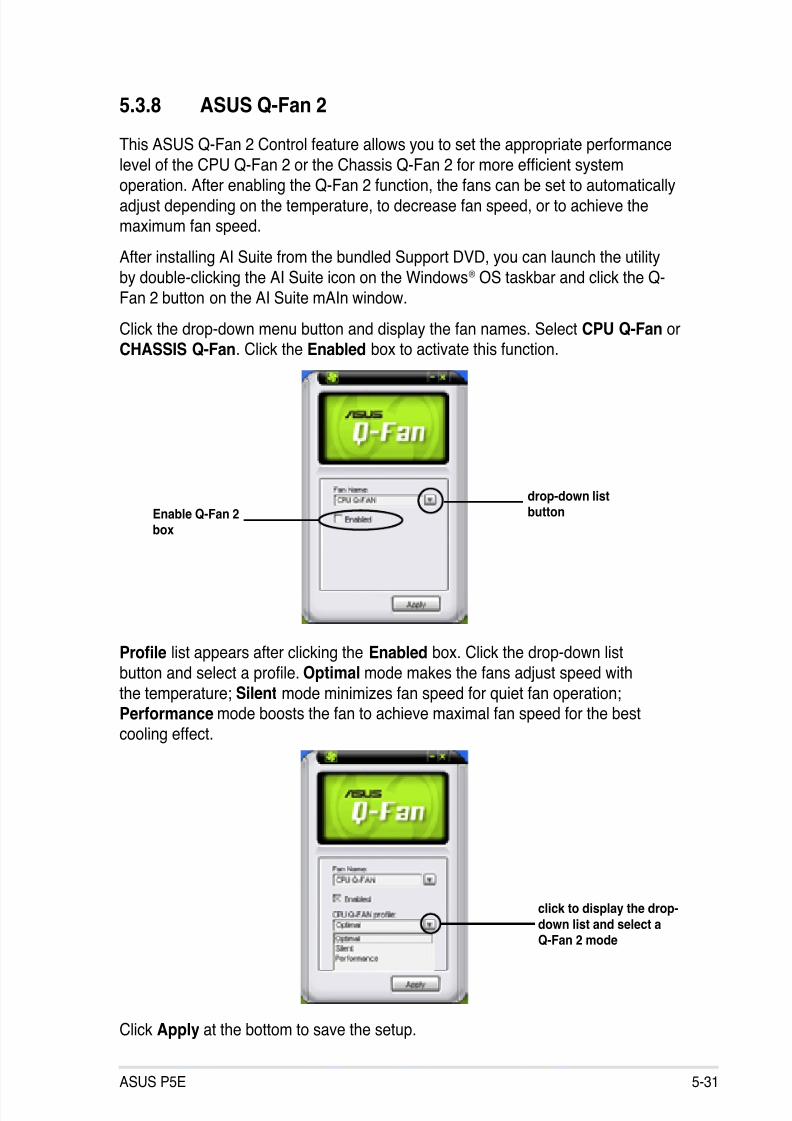
8/13/2019 Asus P5E Motherboard User Guide
http://slidepdf.com/reader/full/asus-p5e-motherboard-user-guide 139/174
ASUS P5E 5-31
5.3.8 ASUS Q-Fan 2
This ASUS Q-Fan 2 Control feature allows you to set the appropriate performance
level of the CPU Q-Fan 2 or the Chassis Q-Fan 2 for more efcient system
operation. After enabling the Q-Fan 2 function, the fans can be set to automaticallyadjust depending on the temperature, to decrease fan speed, or to achieve themaximum fan speed.
After installing AI Suite from the bundled Support DVD, you can launch the utility
by double-clicking the AI Suite icon on the Windows® OS taskbar and click the Q-
Fan 2 button on the AI Suite mAIn window.
Click the drop-down menu button and display the fan names. Select CPU Q-Fan or
CHASSIS Q-Fan. Click the Enabled box to activate this function.
drop-down listbuttonEnable Q-Fan 2
box
Prole list appears after clicking the Enabled box. Click the drop-down list
button and select a prole. Optimal mode makes the fans adjust speed with
the temperature; Silent mode minimizes fan speed for quiet fan operation;Performance mode boosts the fan to achieve maximal fan speed for the best
cooling effect.
click to display the drop-down list and select a
Q-Fan 2 mode
Click Apply at the bottom to save the setup.
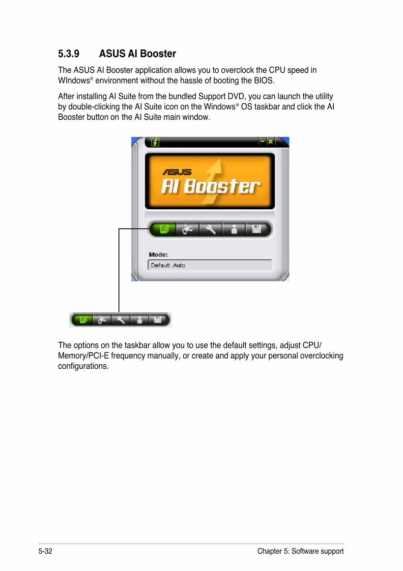
8/13/2019 Asus P5E Motherboard User Guide
http://slidepdf.com/reader/full/asus-p5e-motherboard-user-guide 140/174
5-32 Chapter 5: Software support
5.3.9 ASUS AI Booster
The ASUS AI Booster application allows you to overclock the CPU speed in
WIndows® environment without the hassle of booting the BIOS.
After installing AI Suite from the bundled Support DVD, you can launch the utilityby double-clicking the AI Suite icon on the Windows® OS taskbar and click the AI
Booster button on the AI Suite main window.
The options on the taskbar allow you to use the default settings, adjust CPU/
Memory/PCI-E frequency manually, or create and apply your personal overclocking
congurations.
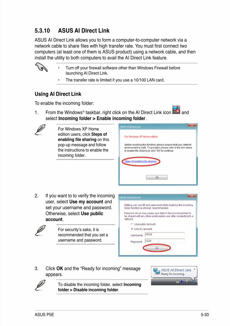
8/13/2019 Asus P5E Motherboard User Guide
http://slidepdf.com/reader/full/asus-p5e-motherboard-user-guide 141/174
ASUS P5E 5-33
5.3.10 ASUS AI Direct Link
ASUS AI Direct Link allows you to form a computer-to-computer network via a
network cable to share les with high transfer rate. You must rst connect two
computers (at least one of them is ASUS product) using a network cable, and theninstall the utility to both computers to avail the AI Direct Link feature.
• Turn off your rewall software other than Windows Firewall before
launching AI Direct Link.
• The transfer rate is limited if you use a 10/100 LAN card.
Using AI Direct Link
To enable the incoming folder:
1. From the Windows® taskbar, right click on the AI Direct Link icon and
select Incoming folder > Enable incoming folder.
2. If you want to to verify the incoming
user, select Use my account and
set your username and password.
Otherwise, select Use public
account.
For security’s sake, it is
recommended that you set ausername and password.
3. Click OK and the “Ready for incoming” messageappears.
To disable the incoming folder, select Incomingfolder > Disable incoming folder.
For Windows XP Homeedition users, click Steps ofenabling le sharing on thispop-up message and followthe instructions to enable theincoming folder.
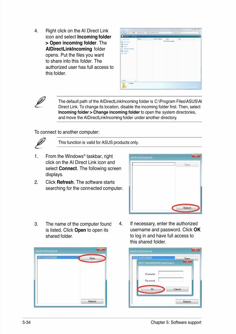
8/13/2019 Asus P5E Motherboard User Guide
http://slidepdf.com/reader/full/asus-p5e-motherboard-user-guide 142/174
5-34 Chapter 5: Software support
The default path of the AIDirectLinkIncoming folder is C:\Program Files\ASUS\AIDirect Link. To change its location, disable the incoming folder rst. Then, select
Incoming folder > Change incoming folder to open the system directories,and move the AIDirectLinkIncoming folder under another directory.
To connect to another computer:
This function is valid for ASUS products only.
1. From the Windows® taskbar, right
click on the AI Direct Link icon and
select Connect. The following screendisplays.
2. Click Refresh. The software starts
searching for the connected computer.
3. The name of the computer foundis listed. Click Open to open its
shared folder.
4. If necessary, enter the authorizedusername and password. Click OK
to log in and have full access tothis shared folder.
4. Right click on the AI Direct Linkicon and select Incoming folder> Open incoming folder. The
AIDirectLinkIncoming folder
opens. Put the les you wantto share into this folder. The
authorized user has full access tothis folder.
8/13/2019 Asus P5E Motherboard User Guide
http://slidepdf.com/reader/full/asus-p5e-motherboard-user-guide 143/174
P5E 5-35
5.4 RAID congurations
The motherboard comes with the Intel® ICH9R Southbridge RAID controller that
allows you to congure IDE and Serial ATA hard disk drives as RAID sets.
5.4.1 RAID denitionsRAID 0 (Data striping) optimizes two identical hard disk drives to read and writedata in parallel, interleaved stacks. Two hard disks perform the same work as a
single drive but at a sustained data transfer rate, double that of a single disk alone,
thus improving data access and storage. Use of two new identical hard disk drivesis required for this setup.
RAID 1 (Data mirroring) copies and maintains an identical image of data from one
drive to a second drive. If one drive fails, the disk array management software
directs all applications to the surviving drive as it contains a complete copy ofthe data in the other drive. This RAID conguration provides data protection andincreases fault tolerance to the entire system. Use two new drives or use an
existing drive and a new drive for this setup. The new drive must be of the same
size or larger than the existing drive.
RAID 10 is data striping and data mirroring combined without parity (redundancy
data) having to be calculated and written. With the RAID 10 conguration you getall the benets of both RAID 0 and RAID 1 congurations. Use four new hard diskdrives or use an existing drive and three new drives for this setup.
RAID 5 stripes both data and parity information across three or more hard
disk drives. Among the advantages of RAID 5 conguration include betterHDD performance, fault tolerance, and higher storage capacity. The RAID
5 conguration is best suited for transaction processing, relational databaseapplications, enterprise resource planning, and other business systems. Use aminimum of three identical hard disk drives for this setup.
Intel® Matrix Storage. The Intel® Matrix Storage technology supported by the
ICH9R chip allows you to create a RAID 0, RAID 1, RAID 5, and RAID 10 function
to improve both system performance and data safety. You can also combine twoRAID sets to get higher performance, capacity, or fault tolerance provided by thedifference RAID function. For example, RAID 0 and RAID 1 set can be created by
using only two identical hard disk drives.
If you want to boot the system from a hard disk drive included in a created RAIDset, copy rst the RAID driver from the support DVD to a oppy disk/USB device
before you install an operating system to the selected hard disk drive. Refer tosection 5.5 Creating a RAID driver disk for details.
8/13/2019 Asus P5E Motherboard User Guide
http://slidepdf.com/reader/full/asus-p5e-motherboard-user-guide 144/174
5-36 Chapter 5: Software support
5.4.3 Intel® RAID congurations
This motherboard supports RAID 0, RAID 1, RAID 5, RAID 10 (0+1) and Intel ®
Matrix Storage congurations for Serial ATA hard disks drives through the Intel®
ICH8R Southbridge chip.
Setting the RAID item in BIOS
You must set the RAID item in the BIOS Setup before you can create a RAIDset(s). To do this:
1. Enter the BIOS Setup during POST.2. Go to the Main Menu, select IDE Conguration, then press <Enter>.
3. Select the item Congure SATA As, then press <Enter> to display theconguration options.
4. Select RAID from the Congure SATA As item options, then press <Enter>.
5. Select the item Onboard Serial-ATA BOOTROM, press <Enter>, then select
Enabled from the options.
6. Save your changes, then exit the BIOS Setup.
Refer to the system or the motherboard user guide for details on entering andnavigating through the BIOS Setup.
5.4.2 Installing Serial ATA hard disks
The motherboard supports Serial ATA hard disk drives. For optimal performance,install identical drives of the same model and capacity when creating a disk array.
To install the SATA hard disks for a RAID conguration:
1. Install the SATA hard disks into the drive bays.
2. Connect the SATA signal cables.
3. Connect a SATA power cable to the power connector on each drive.
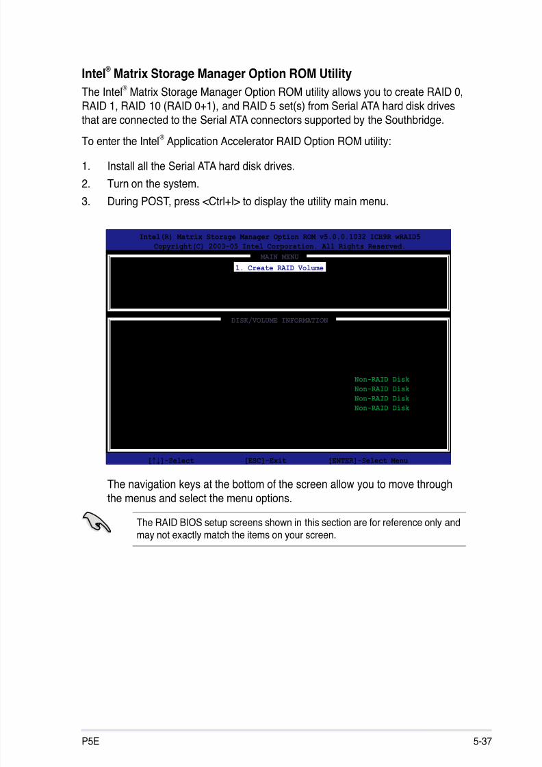
8/13/2019 Asus P5E Motherboard User Guide
http://slidepdf.com/reader/full/asus-p5e-motherboard-user-guide 145/174
P5E 5-37
Intel® Matrix Storage Manager Option ROM Utility
The Intel® Matrix Storage Manager Option ROM utility allows you to create RAID 0,
RAID 1, RAID 10 (RAID 0+1), and RAID 5 set(s) from Serial ATA hard disk drives
that are connected to the Serial ATA connectors supported by the Southbridge.
To enter the Intel® Application Accelerator RAID Option ROM utility:
1. Install all the Serial ATA hard disk drives.
2. Turn on the system.
3. During POST, press <Ctrl+I> to display the utility main menu.
Intel(R) Matrix Storage Manager Option ROM v5.0.0.1032 ICH9R wRAID5
Copyright(C) 2003-05 Intel Corporation. All Rights Reserved.
[ MAIN MENU ] 1. Create RAID Volume
2. Delete RAID Volume
3. Reset Disks to Non-RAID
4. Exit
[ DISK/VOLUME INFORMATION ]
RAID Volumes:
None dened.
Physical Disks:
Port Drive Model Serial # Size Type/Status(Vol ID)
0 XXXXXXXXXXX XXXXXXXX XX.XXGB Non-RAID Disk
1 XXXXXXXXXXX XXXXXXXX XX.XXGB Non-RAID Disk
2 XXXXXXXXXXX XXXXXXXX XX.XXGB Non-RAID Disk
3 XXXXXXXXXXX XXXXXXXX XX.XXGB Non-RAID Disk
[↑↓]-Select [ESC]-Exit [ENTER]-Select Menu
The navigation keys at the bottom of the screen allow you to move through
the menus and select the menu options.
The RAID BIOS setup screens shown in this section are for reference only andmay not exactly match the items on your screen.
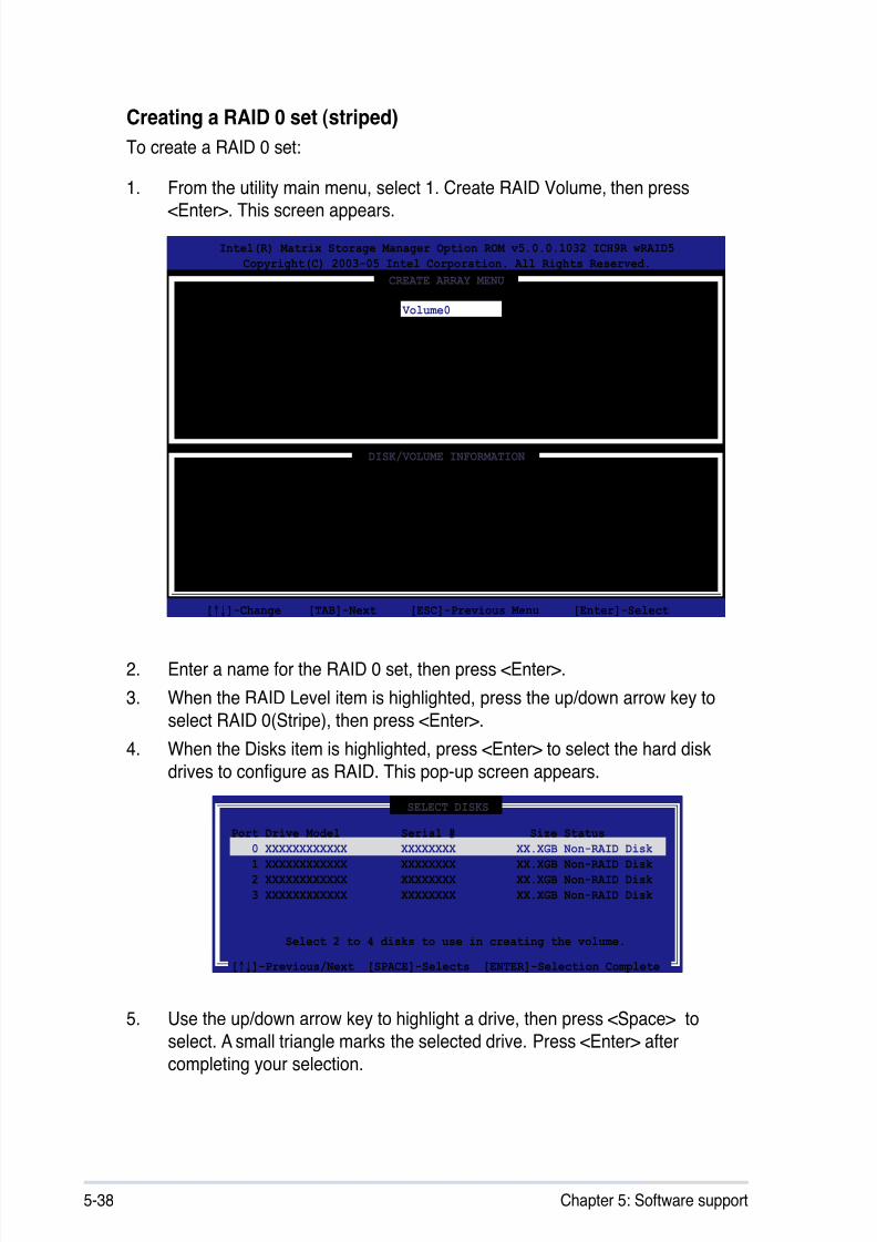
8/13/2019 Asus P5E Motherboard User Guide
http://slidepdf.com/reader/full/asus-p5e-motherboard-user-guide 146/174
5-38 Chapter 5: Software support
Creating a RAID 0 set (striped)
To create a RAID 0 set:
1. From the utility main menu, select 1. Create RAID Volume, then press
<Enter>. This screen appears.
2. Enter a name for the RAID 0 set, then press <Enter>.
3. When the RAID Level item is highlighted, press the up/down arrow key to
select RAID 0(Stripe), then press <Enter>.
4. When the Disks item is highlighted, press <Enter> to select the hard disk
drives to congure as RAID. This pop-up screen appears.
Intel(R) Matrix Storage Manager Option ROM v5.0.0.1032 ICH9R wRAID5
Copyright(C) 2003-05 Intel Corporation. All Rights Reserved.
[ CREATE ARRAY MENU ]
[ DISK/VOLUME INFORMATION ]
Enter a string between 1 and 16 characters in length that can be used to uniquely identify the RAID volume. This name is case sensitive and
cannot contain special characters.
[↑↓]-Change [TAB]-Next [ESC]-Previous Menu [Enter]-Select
Name:
RAID Level:
Disks:
Strip Size:
Capacity:
Volume0
RAID0(Stripe)
Select Disks
128KB
0.0 GB
Create Volume
[ SELECT DISKS ]
[↑↓]-Previous/Next [SPACE]-Selects [ENTER]-Selection Complete
Port Drive Model Serial # Size Status
0 XXXXXXXXXXXX XXXXXXXX XX.XGB Non-RAID Disk
1 XXXXXXXXXXXX XXXXXXXX XX.XGB Non-RAID Disk
2 XXXXXXXXXXXX XXXXXXXX XX.XGB Non-RAID Disk
3 XXXXXXXXXXXX XXXXXXXX XX.XGB Non-RAID Disk
Select 2 to 4 disks to use in creating the volume.
5. Use the up/down arrow key to highlight a drive, then press <Space> to
select. A small triangle marks the selected drive. Press <Enter> aftercompleting your selection.
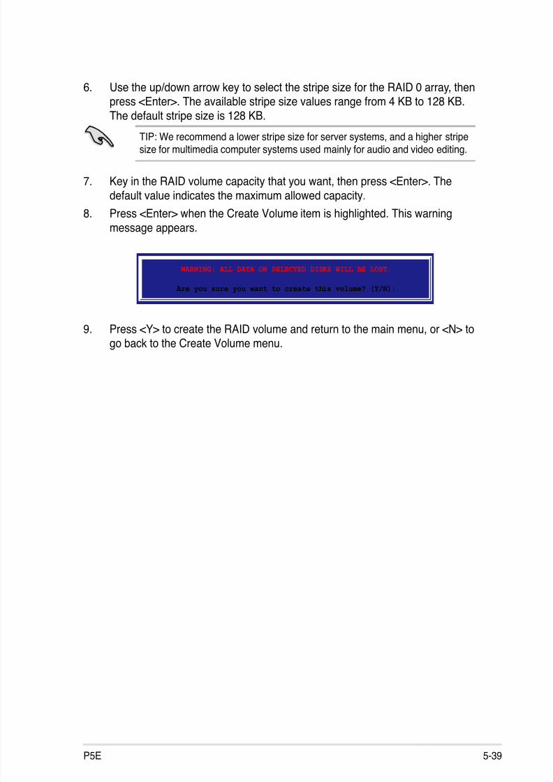
8/13/2019 Asus P5E Motherboard User Guide
http://slidepdf.com/reader/full/asus-p5e-motherboard-user-guide 147/174
P5E 5-39
6. Use the up/down arrow key to select the stripe size for the RAID 0 array, thenpress <Enter>. The available stripe size values range from 4 KB to 128 KB.The default stripe size is 128 KB.
TIP: We recommend a lower stripe size for server systems, and a higher stripesize for multimedia computer systems used mainly for audio and video editing.
7. Key in the RAID volume capacity that you want, then press <Enter>. The
default value indicates the maximum allowed capacity.
8. Press <Enter> when the Create Volume item is highlighted. This warning
message appears.
WARNING: ALL DATA ON SELECTED DISKS WILL BE LOST.
Are you sure you want to create this volume? (Y/N):
9. Press <Y> to create the RAID volume and return to the main menu, or <N> togo back to the Create Volume menu.
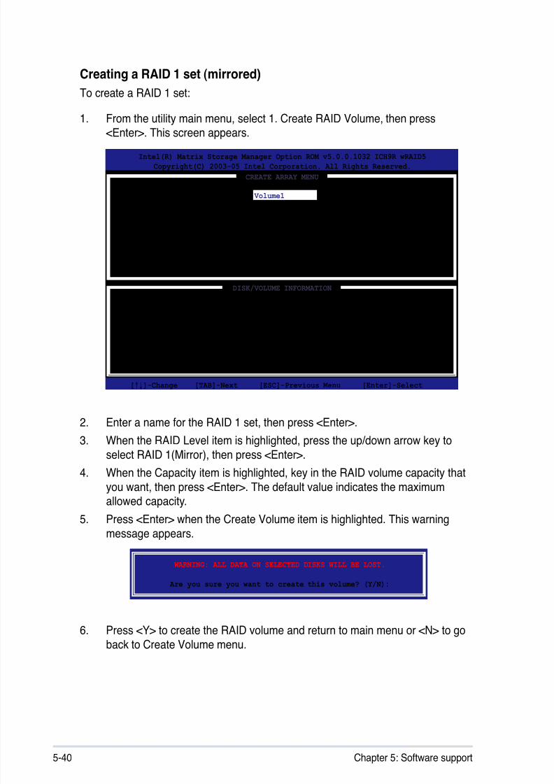
8/13/2019 Asus P5E Motherboard User Guide
http://slidepdf.com/reader/full/asus-p5e-motherboard-user-guide 148/174
5-40 Chapter 5: Software support
Creating a RAID 1 set (mirrored)
To create a RAID 1 set:
1. From the utility main menu, select 1. Create RAID Volume, then press
<Enter>. This screen appears.
2. Enter a name for the RAID 1 set, then press <Enter>.
3. When the RAID Level item is highlighted, press the up/down arrow key to
select RAID 1(Mirror), then press <Enter>.
4. When the Capacity item is highlighted, key in the RAID volume capacity that
you want, then press <Enter>. The default value indicates the maximumallowed capacity.
5. Press <Enter> when the Create Volume item is highlighted. This warningmessage appears.
Intel(R) Matrix Storage Manager Option ROM v5.0.0.1032 ICH9R wRAID5
Copyright(C) 2003-05 Intel Corporation. All Rights Reserved.
[ CREATE ARRAY MENU ]
[ DISK/VOLUME INFORMATION ]
Enter a string between 1 and 16 characters in length that can be used to uniquely identify the RAID volume. This name is case sensitive and
cannot contain special characters.
[↑↓]-Change [TAB]-Next [ESC]-Previous Menu [Enter]-Select
Name:
RAID Level:
Disks:
Strip Size:
Capacity:
Volume1
RAID1(Mirror)
Select Disks
N/A
XX.X GB
Create Volume
WARNING: ALL DATA ON SELECTED DISKS WILL BE LOST.
Are you sure you want to create this volume? (Y/N):
6. Press <Y> to create the RAID volume and return to main menu or <N> to go
back to Create Volume menu.
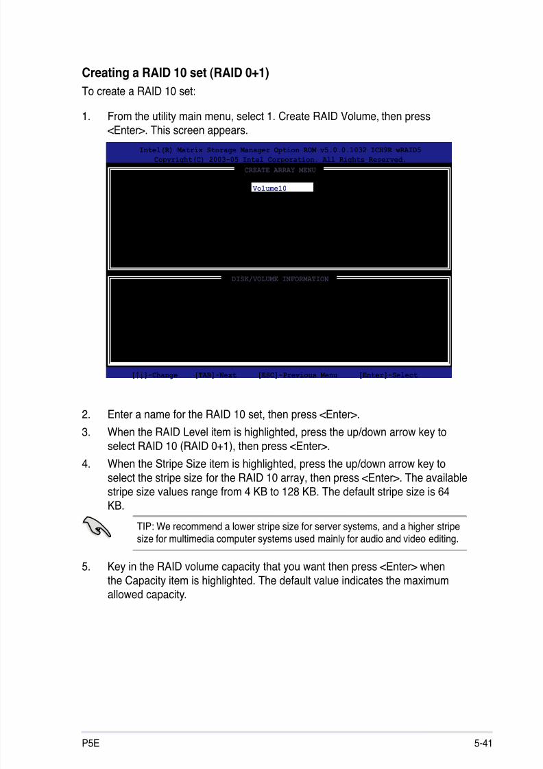
8/13/2019 Asus P5E Motherboard User Guide
http://slidepdf.com/reader/full/asus-p5e-motherboard-user-guide 149/174
P5E 5-41
Creating a RAID 10 set (RAID 0+1)
To create a RAID 10 set:
1. From the utility main menu, select 1. Create RAID Volume, then press
<Enter>. This screen appears.
Intel(R) Matrix Storage Manager Option ROM v5.0.0.1032 ICH9R wRAID5
Copyright(C) 2003-05 Intel Corporation. All Rights Reserved.
[ CREATE ARRAY MENU ]
[ DISK/VOLUME INFORMATION ]
Enter a string between 1 and 16 characters in length that can be used to uniquely identify the RAID volume. This name is case sensitive and
cannot contain special characters.
Name:
RAID Level:
Disks:
Strip Size:
Capacity:
Volume10
RAID10(RAID0+1)
Select Disks
128KB
XXX.X GB
Create Volume
2. Enter a name for the RAID 10 set, then press <Enter>.
3. When the RAID Level item is highlighted, press the up/down arrow key to
select RAID 10 (RAID 0+1), then press <Enter>.
4. When the Stripe Size item is highlighted, press the up/down arrow key toselect the stripe size for the RAID 10 array, then press <Enter>. The availablestripe size values range from 4 KB to 128 KB. The default stripe size is 64KB.
TIP: We recommend a lower stripe size for server systems, and a higher stripesize for multimedia computer systems used mainly for audio and video editing.
5. Key in the RAID volume capacity that you want then press <Enter> when
the Capacity item is highlighted. The default value indicates the maximumallowed capacity.
[↑↓]-Change [TAB]-Next [ESC]-Previous Menu [Enter]-Select
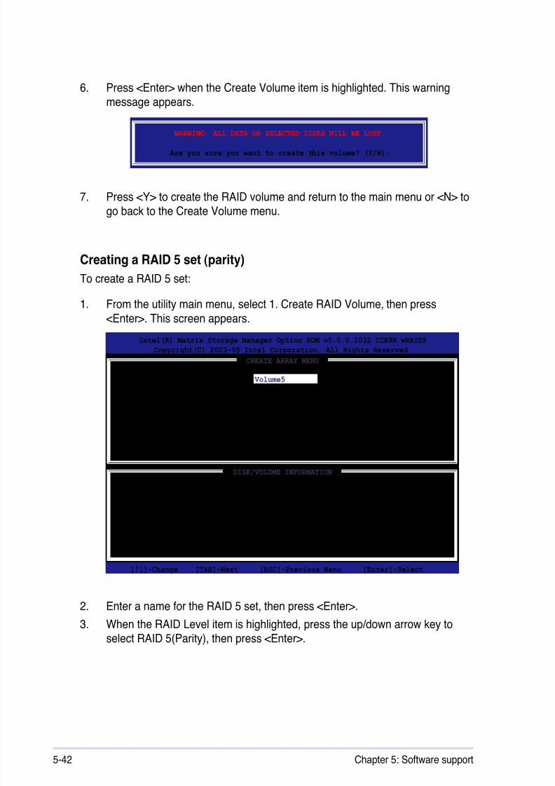
8/13/2019 Asus P5E Motherboard User Guide
http://slidepdf.com/reader/full/asus-p5e-motherboard-user-guide 150/174
5-42 Chapter 5: Software support
Creating a RAID 5 set (parity)To create a RAID 5 set:
1. From the utility main menu, select 1. Create RAID Volume, then press
<Enter>. This screen appears.
Intel(R) Matrix Storage Manager Option ROM v5.0.0.1032 ICH9R wRAID5
Copyright(C) 2003-05 Intel Corporation. All Rights Reserved.
[ CREATE ARRAY MENU ]
[ DISK/VOLUME INFORMATION ]
Enter a string between 1 and 16 characters in length that can be used to uniquely identify the RAID volume. This name is case sensitive and
cannot contain special characters.
Name:
RAID Level:
Disks:
Strip Size:
Capacity:
Volume5
RAID5(Parity)
Select Disks
64KB
0.0 GB
Create Volume
WARNING: ALL DATA ON SELECTED DISKS WILL BE LOST.
Are you sure you want to create this volume? (Y/N):
7. Press <Y> to create the RAID volume and return to the main menu or <N> togo back to the Create Volume menu.
[↑↓]-Change [TAB]-Next [ESC]-Previous Menu [Enter]-Select
6. Press <Enter> when the Create Volume item is highlighted. This warningmessage appears.
2. Enter a name for the RAID 5 set, then press <Enter>.
3. When the RAID Level item is highlighted, press the up/down arrow key toselect RAID 5(Parity), then press <Enter>.

8/13/2019 Asus P5E Motherboard User Guide
http://slidepdf.com/reader/full/asus-p5e-motherboard-user-guide 151/174
P5E 5-43
4. The Disks item is highlighted, press <Enter> to select the hard disk drives to
congure as RAID. The following pop-up screen appears.
[ SELECT DISKS ]
[↑↓]-Previous/Next [SPACE]-Selects [ENTER]-Selection Complete
Port Drive Model Serial # Size Status
0 XXXXXXXXXXXX XXXXXXXX XX.XGB Non-RAID Disk
1 XXXXXXXXXXXX XXXXXXXX XX.XGB Non-RAID Disk
2 XXXXXXXXXXXX XXXXXXXX XX.XGB Non-RAID Disk
3 XXXXXXXXXXXX XXXXXXXX XX.XGB Non-RAID Disk
Select 2 to 4 disks to use in creating the volume.
5. Use the up/down arrow key to highlight the drive you want to set, then press
<Space> to select. A small triangle marks the selected drive. Press <Enter>after completing your selection.
6. When the Stripe Size item is highlighted, press the up/down arrow keyto select the stripe size for the RAID 5 array, then press <Enter>.The available stripe size values range from 4 KB to 128 KB. The default stripesize is 64 KB.
TIP: We recommend a lower stripe size for server systems, and a higher stripesize for multimedia computer systems used mainly for audio and video editing.
7. Key in the RAID volume capacity that you want, then press <Enter> whenthe Capacity item is highlighted. The default value indicates the maximum
allowed capacity.
8. Press <Enter> when the Create Volume item is highlighted. This warning
message appears.
WARNING: ALL DATA ON SELECTED DISKS WILL BE LOST.
Are you sure you want to create this volume? (Y/N):
9. Press <Y> to create the RAID volume and return to the main menu or <N> to
go back to the Create Volume menu.
8/13/2019 Asus P5E Motherboard User Guide
http://slidepdf.com/reader/full/asus-p5e-motherboard-user-guide 152/174
5-44 Chapter 5: Software support
5.5 Creating a RAID driver disk
A oppy disk with the RAID driver is required when installing Windows® XP
operating system on a hard disk drive that is included in a RAID set. For Windows®
Vista™ operating system, use either a oppy disk or a USB device with the RAID
driver.
5.5.1 Creating a RAID driver disk without entering the OS
To create a RAID/SATA driver disk without entering the OS:
1. Boot your computer.
2. Press <Del> during POST to enter the BIOS setup utility.
3. Set the optical drive as the primary boot device.
4. Insert the support DVD into the optical drive.5. Save changes and exit BIOS.
6. Press any key when the system prompts “Press any key to boot from the opticaldrive.”
7. When the menu appears, press <1> to create a RAID driver disk.
8. Insert a formatted oppy disk into the oppy drive then press <Enter>.
9. Follow succeeding screen instructions to complete the process.
5.5.2 Creating a RAID/SATA driver disk in Windows®
To create a RAID driver disk in Windows®:
1. Start Windows®.
2. Place the motherboard support DVD into the optical drive.
3. Go to the Make Disk menu, then click Intel ICH9 32/64bit RAID/AHCI Driver to create an Intel® ICH9R RAID driver disk.
4. Insert a oppy disk/USB device into the oppy disk drive/USB port.5. Follow succeeding screen instructions to complete the process.
Write-protect the oppy disk to avoid computer virus infection.
To install the RAID driver in Windows® XP:
1. During the OS installation, the system prompts you to press the F6 key to installthird-party SCSI or RAID driver.
2. Press <F6> then insert the oppy disk with RAID driver into the oppy diskdrive.
3. When prompted to select the SCSI adapter to install, make sure you select
ICH9R.
4. Follow the succeeding screen instructions to complete the installation.

8/13/2019 Asus P5E Motherboard User Guide
http://slidepdf.com/reader/full/asus-p5e-motherboard-user-guide 153/174
P5E 5-45
To install the RAID driver in Windows® Vista™:
1. Insert the oppy disk/USB device with RAID driver into the oppy disk drive/USBport.
2. During the OS installation, select Intel ICH9R.
3. Follow the succeeding screen instructions to complete the installation.

8/13/2019 Asus P5E Motherboard User Guide
http://slidepdf.com/reader/full/asus-p5e-motherboard-user-guide 154/174
5-46 Chapter 5: Software support

8/13/2019 Asus P5E Motherboard User Guide
http://slidepdf.com/reader/full/asus-p5e-motherboard-user-guide 155/174
6
This chapter tells how to install ATI®
CrossFire™ graphics cards to avail of
ATI’s Multi-Video Processing technology.
ATI® CrossFire™technology support

8/13/2019 Asus P5E Motherboard User Guide
http://slidepdf.com/reader/full/asus-p5e-motherboard-user-guide 156/174
ASUS P5E
Chapter summary 66.1 Overview ....................................................................................... 6-1
6.2 Installing CrossFire™ graphics cards ....................................... 6-2
6.3 Software information ................................................................... 6-5
8/13/2019 Asus P5E Motherboard User Guide
http://slidepdf.com/reader/full/asus-p5e-motherboard-user-guide 157/174
ASUS P5E 6-1
6.1 Overview
The motherboard supports the ATI® CrossFire™ technology that allows you toinstall multi-graphics processing units (GPU) graphics cards. Follow the installation
procedures in this section.
6.1.1 Requirements
• CrossFire™ Edition graphics card (Master)
• CrossFire™-ready graphics card (Slave)
• CrossFire™-ready motherboard
• Make sure that your power supply unit (PSU) can provide at least theminimum power required by your system. See 9. ATX Power connectors on
page 2-33 for details.
6.1.2 Before you begin
Uninstall other graphics card drivers in your system
To uninstall other graphics card drivers:
1. Close all current applications.
2. Go to Control Panel > Add/Remove Programs.
3. Select your current graphics card driver/s.
4. Select Add/Remove.
5. Restart your system.
• Visit the ATI website or download the Radeon® X850 Crossre™ EditionUser’s Guide from the support DVD for detailed hardware requirements and
installation procedures.
• The ATI CrossFire™ technology supports only the following operating
systems:- Windows® XP 32-bit (Home or Professional) with Service
Pack 2 (SP2)- Windows® XP Professional 64-bit Edition.
• Make sure that your graphics card driver supports the ATI® CrossFire™Technology. Download the latest driver from the ATI website (www.ati.com)
• The maximum resolution of Radeon™ X850 CrossFire™ Edition is 1600 x1200 at 65 MHz when you use DVI output.

8/13/2019 Asus P5E Motherboard User Guide
http://slidepdf.com/reader/full/asus-p5e-motherboard-user-guide 158/174
6-2 Chapter 6: ATI® MVP technology support
Slave graphics card Master graphics card
2. Insert the CrossFire™ Edition (Master) graphics card into the PCI Express
x16_1 slot. Make sure that the card is properly seated on the slot.
6.2 Installing CrossFire™ graphics cards
Before installing a CrossFire™ system, refer to the user guide that came withthe ATI® CrossFire™ Edition graphics card.
To install the graphics cards:
1. Prepare one CrossFire™ Edition (Master) graphics card and one
CrossFire™-ready (Slave) graphics card.
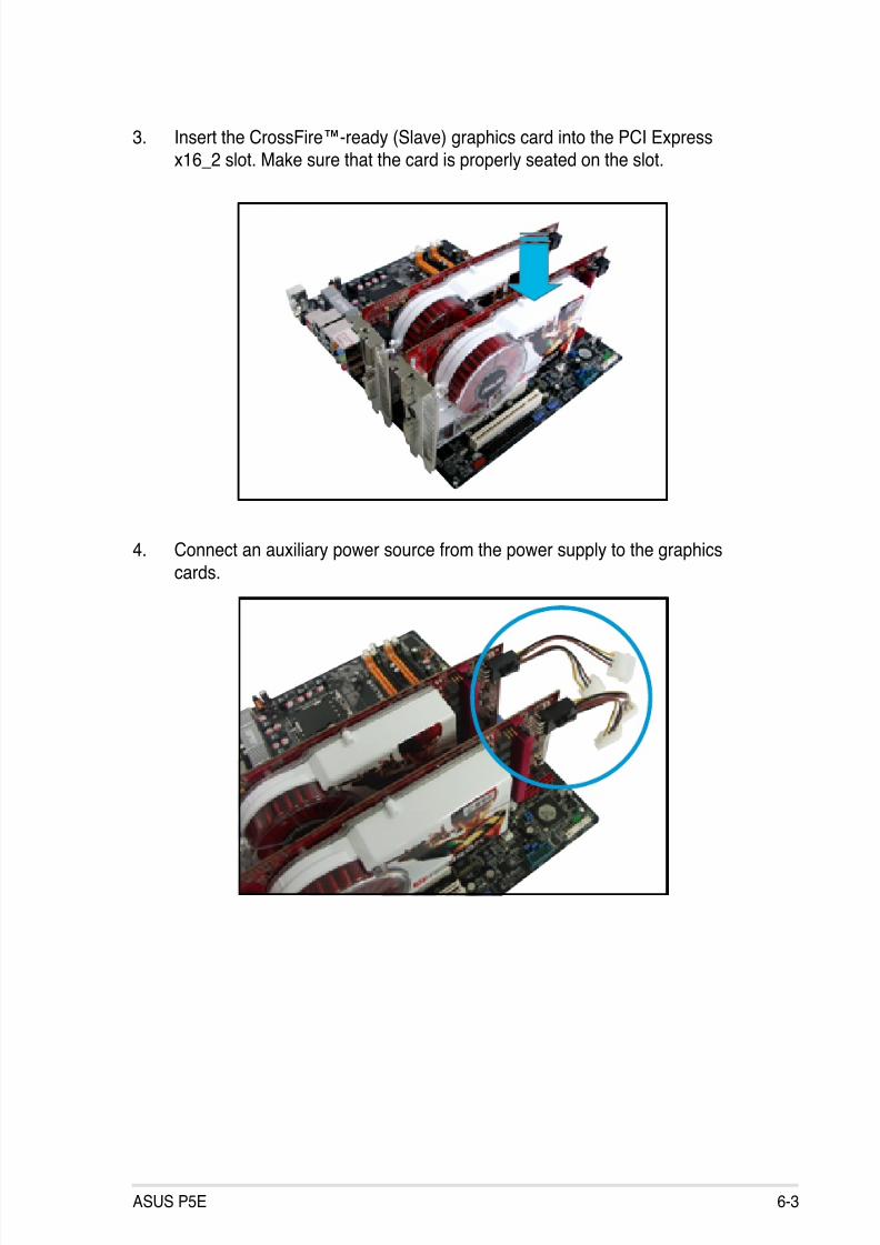
8/13/2019 Asus P5E Motherboard User Guide
http://slidepdf.com/reader/full/asus-p5e-motherboard-user-guide 159/174
ASUS P5E 6-3
3. Insert the CrossFire™-ready (Slave) graphics card into the PCI Expressx16_2 slot. Make sure that the card is properly seated on the slot.
4. Connect an auxiliary power source from the power supply to the graphics
cards.

8/13/2019 Asus P5E Motherboard User Guide
http://slidepdf.com/reader/full/asus-p5e-motherboard-user-guide 160/174
6-4 Chapter 6: ATI® MVP technology support
6. Connect the other end of the external cable to the Slave graphics card.
7. Connect the loose end to the corresponding port on your monitor.
5. Connect one end of the external cable to the Master graphics card.
7
6
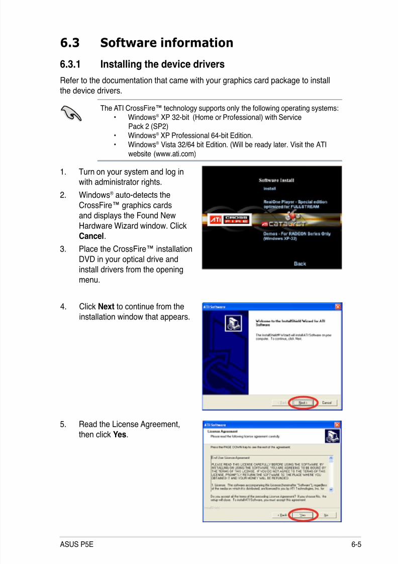
8/13/2019 Asus P5E Motherboard User Guide
http://slidepdf.com/reader/full/asus-p5e-motherboard-user-guide 161/174
ASUS P5E 6-5
6.3 Software information
6.3.1 Installing the device drivers
Refer to the documentation that came with your graphics card package to install
the device drivers.
The ATI CrossFire™ technology supports only the following operating systems:• Windows® XP 32-bit (Home or Professional) with Service
Pack 2 (SP2)• Windows® XP Professional 64-bit Edition.• Windows® Vista 32/64 bit Edition. (Will be ready later. Visit the ATI
website (www.ati.com)
1. Turn on your system and log inwith administrator rights.
2. Windows® auto-detects the
CrossFire™ graphics cards
and displays the Found New
Hardware Wizard window. ClickCancel.
3. Place the CrossFire™ installation
DVD in your optical drive and
install drivers from the opening
menu.
4. Click Next to continue from the
installation window that appears.
5. Read the License Agreement,
then click Yes.
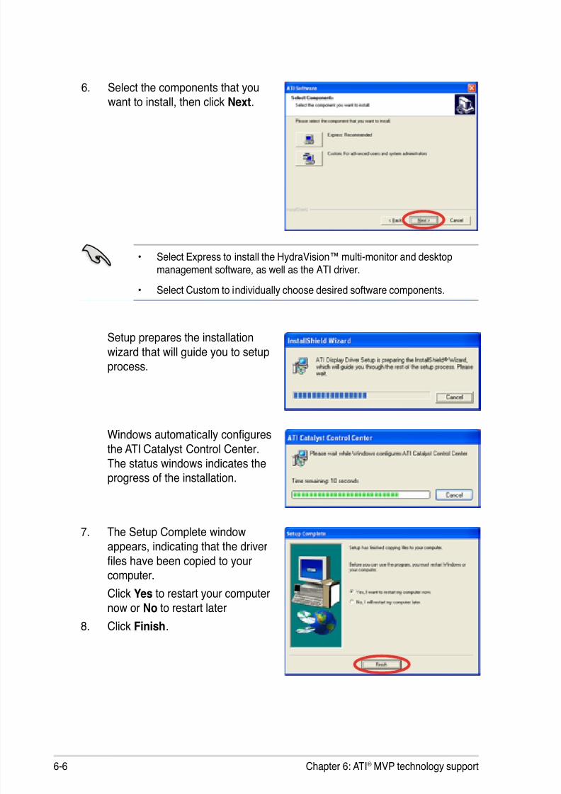
8/13/2019 Asus P5E Motherboard User Guide
http://slidepdf.com/reader/full/asus-p5e-motherboard-user-guide 162/174
6-6 Chapter 6: ATI® MVP technology support
6. Select the components that youwant to install, then click Next.
Setup prepares the installation
wizard that will guide you to setupprocess.
Windows automatically conguresthe ATI Catalyst Control Center.
The status windows indicates theprogress of the installation.
7. The Setup Complete windowappears, indicating that the driver
les have been copied to yourcomputer.
Click Yes to restart your computer
now or No to restart later
8. Click Finish.
• Select Express to install the HydraVision™ multi-monitor and desktopmanagement software, as well as the ATI driver.
• Select Custom to individually choose desired software components.
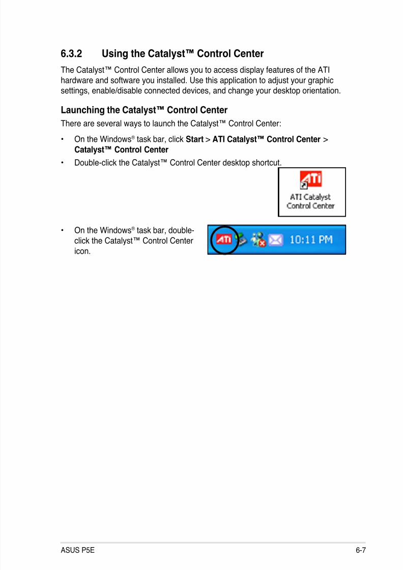
8/13/2019 Asus P5E Motherboard User Guide
http://slidepdf.com/reader/full/asus-p5e-motherboard-user-guide 163/174
ASUS P5E 6-7
6.3.2 Using the Catalyst™ Control Center
The Catalyst™ Control Center allows you to access display features of the ATI
hardware and software you installed. Use this application to adjust your graphic
settings, enable/disable connected devices, and change your desktop orientation.
Launching the Catalyst™ Control Center
There are several ways to launch the Catalyst™ Control Center:
• On the Windows® task bar, click Start > ATI Catalyst™ Control Center >
Catalyst™ Control Center
• Double-click the Catalyst™ Control Center desktop shortcut.
• On the Windows® task bar, double-
click the Catalyst™ Control Center
icon.

8/13/2019 Asus P5E Motherboard User Guide
http://slidepdf.com/reader/full/asus-p5e-motherboard-user-guide 164/174
6-8 Chapter 6: ATI® MVP technology support
The Catalyst™ Control Center Dialog Box
View
The Catalyst™ Control Center provides two views:
Standard - simple view with wizards for beginners
Advance - allows advanced users to access and congure the completefeatures of the software
Set to Advance view to enable the CrossFire™ function.
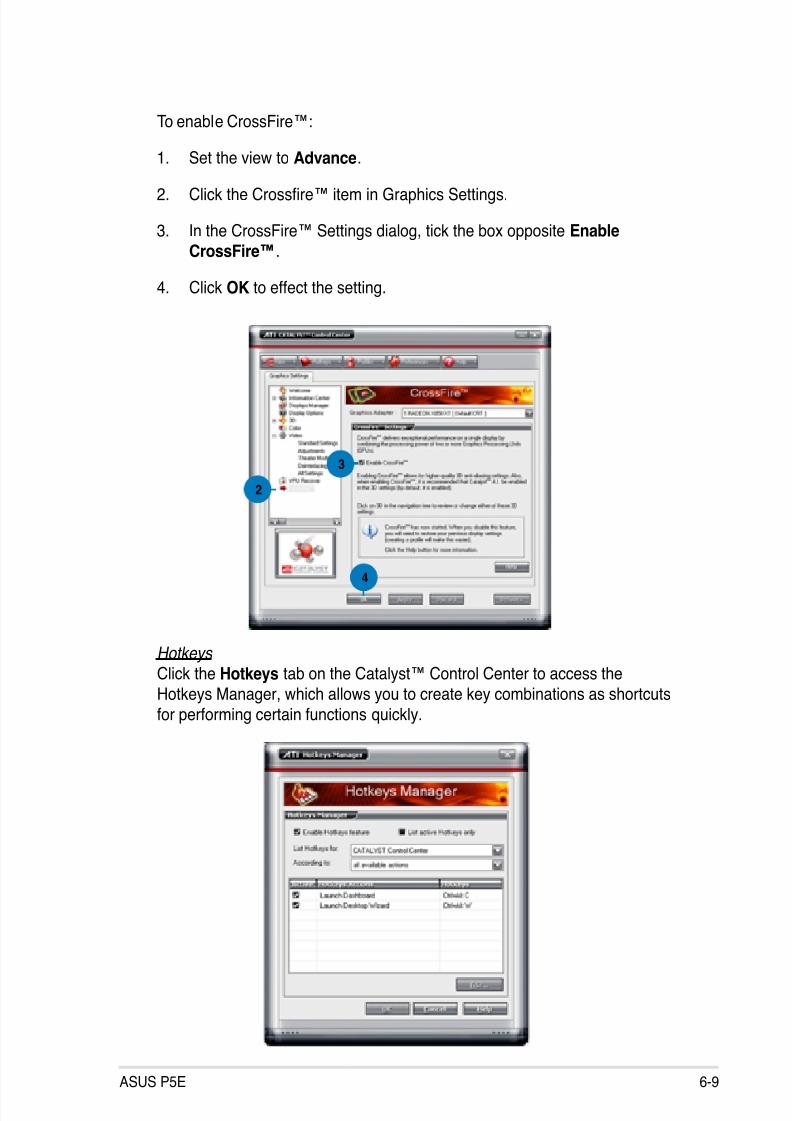
8/13/2019 Asus P5E Motherboard User Guide
http://slidepdf.com/reader/full/asus-p5e-motherboard-user-guide 165/174
ASUS P5E 6-9
To enable CrossFire™:
1. Set the view to Advance.
2. Click the Crossre™ item in Graphics Settings.
3. In the CrossFire™ Settings dialog, tick the box opposite EnableCrossFire™.
4. Click OK to effect the setting.
2
3
4
Hotkeys
Click the Hotkeys tab on the Catalyst™ Control Center to access the
Hotkeys Manager, which allows you to create key combinations as shortcuts
for performing certain functions quickly.
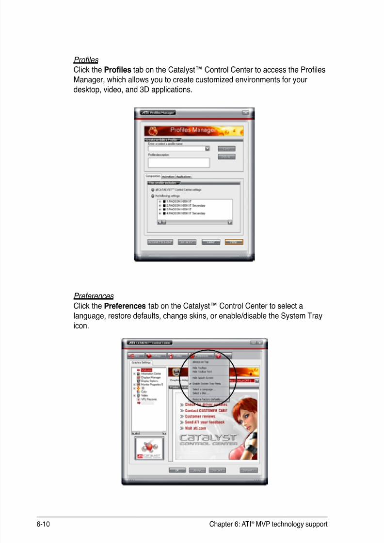
8/13/2019 Asus P5E Motherboard User Guide
http://slidepdf.com/reader/full/asus-p5e-motherboard-user-guide 166/174
6-10 Chapter 6: ATI® MVP technology support
Profiles Click the Proles tab on the Catalyst™ Control Center to access the ProlesManager, which allows you to create customized environments for your
desktop, video, and 3D applications.
Preferences
Click the Preferences tab on the Catalyst™ Control Center to select a
language, restore defaults, change skins, or enable/disable the System Tray
icon.
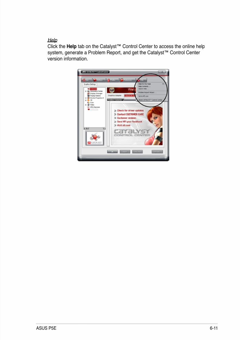
8/13/2019 Asus P5E Motherboard User Guide
http://slidepdf.com/reader/full/asus-p5e-motherboard-user-guide 167/174
ASUS P5E 6-11
Help
Click the Help tab on the Catalyst™ Control Center to access the online help
system, generate a Problem Report, and get the Catalyst™ Control Center
version information.

8/13/2019 Asus P5E Motherboard User Guide
http://slidepdf.com/reader/full/asus-p5e-motherboard-user-guide 168/174
6-12 Chapter 6: ATI® MVP technology support

8/13/2019 Asus P5E Motherboard User Guide
http://slidepdf.com/reader/full/asus-p5e-motherboard-user-guide 169/174
ACPU features
The Appendix describes the CPU features
and technologies that the motherboardsupports as well as the debug code table
for the LCD Poster.
8/13/2019 Asus P5E Motherboard User Guide
http://slidepdf.com/reader/full/asus-p5e-motherboard-user-guide 170/174
P5E
Chapter summary
AA.1 Intel® EM64T ..................................................................................A-1
A.2 Enhanced Intel SpeedStep® Technology (EIST) ........................A-1
A.3 Intel® Hyper-Threading Technology ...........................................A-3
A.4 Debug Code Table ........................................................................A-4

8/13/2019 Asus P5E Motherboard User Guide
http://slidepdf.com/reader/full/asus-p5e-motherboard-user-guide 171/174
P5E A-1
A.1 Intel® EM64T
• The motherboard is fully compatible with Intel® LGA775 processors running
on 32-bit operating systems.
• The motherboard comes with a BIOS le that supports EM64T. You candownload the latest BIOS le from the ASUS website (www.asus.com/ support/download/) if you need to update the BIOS le. See Chapter 4 for
details.
• Visit www.intel.com for more information on the EM64T feature.
• Visit www.microsoft.com for more information on Windows® 64-bit OS.
Using the Intel® EM64T feature
To use the Intel
®
EM64T feature:
1. Install an Intel® CPU that supports the Intel® EM64T.
2. Install a 64-bit operating system (Windows® Vista 64-bit Edition orWindows® XP Professional x64 Edition).
3. Install the 64-bit drivers for the motherboard components and devices from
the support DVD.
4. Install the 64-bit drivers for expansion cards or add-on devices, if any.
Refer to the expansion card or add-on device(s) documentation, or visit therelated website, to verify if the card/device supports a 64-bit system.
A.2 Enhanced Intel SpeedStep®
Technology (EIST)
• The motherboard comes with a BIOS le that supports EIST. You can
download the latest BIOS le from the ASUS website (www.asus.com/ support/download/) if you need to update the BIOS. See Chapter 4 fordetails.
• Visit www.intel.com for more information on the EIST feature.
A.2.1 System requirements
Before using EIST, check your system if it meets the following requirements:
• Intel® processor with EIST support
• BIOS le with EIST support
• Operating system with EIST support (Windows® Vista, Windows® XP SP2/
Linux 2.6 kernel or later versions).

8/13/2019 Asus P5E Motherboard User Guide
http://slidepdf.com/reader/full/asus-p5e-motherboard-user-guide 172/174
A-2 Appendix: CPU features
A.2.2 Using the EIST
To use the EIST feature:
1. Turn on the computer, then enter the BIOS Setup.
2. Go to the Advanced Menu, highlight CPU Conguration, then press <Enter>.
3. Set the Intel(R) SpeedStep Technology item to [Automatic], then press
<Enter>. See page 4-26 for details.
4. Press <F10> to save your changes and exit the BIOS setup.
5. After the computer restarts, right click on a blank space on the desktop, then
select Properties from the pop-up menu.
6. When the Display Properties window appears, click the Screen Saver tab.
7. Click the Power button on theMonitor power section to open the
Power Options Properties window.
8. On the Power schemes section,
click , then select any option
except Home/Ofce Desktop orAlways On.
9. Click Apply, then click OK.
10. Close the Display Propertieswindow.
After you adjust the power scheme,
the CPU internal frequency slightly
decreases when the CPU loading is
low.
The screen displays and procedures may vary depending on the operating
system.
8/13/2019 Asus P5E Motherboard User Guide
http://slidepdf.com/reader/full/asus-p5e-motherboard-user-guide 173/174
P5E A-3
A.3 Intel® Hyper-Threading Technology
• The motherboard supports Intel® Pentium
® 4 LGA775 processors with
Hyper-Threading Technology.
• Hyper-Threading Technology is supported under Windows
®
Vista/XP andLinux 2.4.x (kernel) and later versions only. Under Linux, use the Hyper-Threading compiler to compile the code. If you are using any otheroperating systems, disable the Hyper-Threading Technology item in theBIOS to ensure system stability and performance.
• Installing Windows® XP Service Pack 1 or later version is recommended.
• Make sure to enable the Hyper-Threading Technology item in BIOS beforeinstalling a supported operating system.
• For more information on Hyper-Threading Technology, visit www.intel.
com/info/hyperthreading.
Using the Hyper-Threading Technology
To use the Hyper-Threading Technology:
1. Install an Intel® Pentium® 4 CPU that supports Hyper-Threading Technology.
2. Power up the system and enter the BIOS Setup. Under the Advanced Menu,
make sure that the item Hyper-Threading Technology is set to [Enabled].
The BIOS item appears only if you installed a CPU that supports
Hyper-Threading Technology.
3. Restart the computer.

8/13/2019 Asus P5E Motherboard User Guide
http://slidepdf.com/reader/full/asus-p5e-motherboard-user-guide 174/174