Embed Size (px)
Citation preview

ASUC | Guidelines onSafe and e�cient UNDERPINNING AND MINIPILING OPERATIONS
ASUC
Underpinning & Subsidence Repair Techniques | Engineered Foundation Solutions | Retro Fit Basement Construction
Kingsley House, Ganders Business Park , Kingsley, Bordon, Hampshire GU35 9LUTel: +44 (0)1420 471613
www.asuc.org.uk
3rd Edition
ASUC
ASUC is an independent trade association formed by a number of leading contractors to promote professional and technical competence within the underpinning industry. Members offer a comprehensive range of specialist domestic services in: underpinning and subsidence repair techniques, engineered foundation solutions and retrofit basement construction. Any contractor wishing to join ASUC must first undergo a technical, health & safety, insurance and financial audit and make a commitment to prescribed safety procedures.
It publishes a number of useful documents on underpinning and related activities and a comprehensive directory of members all of which are freely available to download via the website. ASUC members offer 10 or 12 year, depending on the nature of the works, insurance backed latent defects guarantees.
Main authors
Rob Withers - ASUC Executive Director David Kitching – Stress UK Ltd Lewis O’Connor – Abbey Pynford Group
Industry comments from
Hurst Pierce and Malcolm Abbey Pynford Group Morcon Foundations
Photographs and Diagrams
Abbey Pynford Group Falcon Structural Repairs Ltd Force Foundations Ltd t/a Basement Force Kixx Ltd – Mike Darby Larsen Foundations Ltd Neil Foundations Ltd Patterson Construction Ltd MJ Rooney Construction U&M Group Although care has been taken to ensure, to the best of our knowledge, that all data and information contained in this document is accurate to the extent that it relates to either matters of fact or accepted practice or matters of opinion at the time of publication, neither ASUCplus, the authors or contributors nor the co-publishers will be liable for any technical, editorial, typographical or other errors or omissions in or misinterpretations of the data and information provided in this document. Since this document may be subject to change and updating, the data and information which it contains is only correct at the time of publication. Compliance with this document does not of itself infer immunity.
Part-funded by
This project has been delivered with support from the CITB Growth Fund, which aims to ensure that the construction industry has the right people, with the right skills, in the right place, at the right time and is equipped to meet the future skills demands of the industry
Guidelines on safe and efficient Underpinning and Mini Piling works directly below or near to existing structures ISBN: 978-0-9545370-0-5 © ASUC: revised March 2015, October 2014 First issued ASUC 2003.
1
ASUC GUIDELINES On safe and efficient Underpinning and Mini Piling works directly below or near to existing structures
CONTENTS
1. EXECUTIVE SUMMARY ......................................................................................................................... 3
2. INTRODUCTION ................................................................................................................................... 5
3. DEFINITIONS ........................................................................................................................................ 7
4. TYPES OF UNDERPINNING AND MINI PILING ...................................................................................... 8
5. TECHNIQUES USED IN UNDERPINNING AND MINI PILING WORKS ................................................... 16
6. MINI PILING ....................................................................................................................................... 19
7. GROUND IMPROVEMENT ................................................................................................................. 24
8. TEMPORARY WORKS ......................................................................................................................... 27
9. IMPACT ON OTHERS .......................................................................................................................... 33
10. FACTORS AFFECTING CHOICE OF CONSTRUCTION TECHNIQUE AND METHOD ............................... 37
11. HEALTH AND SAFETY ......................................................................................................................... 39
12. THE PROJECT TEAM ........................................................................................................................... 49
13. PROCUREMENT ................................................................................................................................. 52
14. INSURANCE ....................................................................................................................................... 55
15. GUARANTEES .................................................................................................................................... 59
16. DOMESTIC PROPERTY OWNER CONSIDERATIONS ............................................................................. 61
17. LIST OF APPENDICES .......................................................................................................................... 64
18. APPENDIX A - SITE INVESTIGATIONS .................................................................................................. 65
19. APPENDIX B - BUILDING DAMAGE CLASSIFICATION .......................................................................... 69
20. APPENDIX C - SAFETY HAZARDS AND MITIGATING ACTIONS ............................................................ 69
21. APPENDIX D - HEALTH HAZARDS AND MITIGATING ACTIONS ........................................................... 77
22. APPENDIX E: PLANNING FOR RISK MANAGEMENT –DETAIL ON INFORMATION REQUIRED .......................................................................................................................................... 82
23. APPENDIX F: ASUC UNDERPINNING AND MINI PILING WORKS INDEMNITY GUARANTEE (DIG) POLICY ..................................................................................................................................... 83
24. APPENDIX G: Construction (Design and Management) Regulations 2015 – CDM 2015. ................. 90
25. GLOSSARY OF TERMS......................................................................................................................... 93
26. REFERENCES ...................................................................................................................................... 94

2
SPECIAL NOTE RELATING TO CDM REGULATIONS AND PUBLICATION
The principle reason for issuing a 3
rd Edition is to enable the section in Appendix G to be added in relation to CDM
2015 and the changes to the law with effect from 6th
April 2015. In addition it has enabled changes due to some of the industry comments, for which ASUC is very grateful.
Published by ASUC Kingsley House, Ganders Business Park, Kingsley, Bordon, Hampshire GU35 9LU www.asuc.org.uk
3
1. EXECUTIVE SUMMARY
The Association of Specialist Underpinning Contractors (ASUC) is publishing these guidelines to improve 1.1the safety and efficiency of underpinning and mini piling construction to reduce negative impact on others, especially people living or working near to underpinning projects.
The objective of these guidelines is to enable clients, designers, engineers and others involved in 1.2Underpinning and Mini Piling works projects to instruct safe and efficient work.
Underpinning and Mini Piling works are a complex form of building involving geotechnical, hydrological, 1.3structural and civil engineering and health and safety expertise that even those with significant construction experience may not have encountered previously.
The single leading principle throughout these guidelines is the absolute priority that health and safety 1.4has over all other aspects of a project.
Temporary works (support to existing buildings and to the ground around excavations) is critical and is 1.5often overlooked or addressed superficially.
The main construction techniques used for Underpinning and Mini Piling works structures are mass 1.6concrete , pile and beam and/or piled rafts
There are two main types of underpinning: mass concrete underpinning and reinforced 1.6.1concrete (RC) underpinning (underpinning piers with reinforced concrete beams).
Mass concrete underpins provide vertical support underneath existing
RC underpins can usually provide vertical support underneath existing walls and retain the ground outside the Underpinning and Mini Piling works
Piers and beams provide a more cost effective solution in some circumstances whereby piers are cast at approx. 3m centres and tied together with an RC beam which is inserted into the existing structure using specialist temporary supports known as “stools”
In Underpinning and Mini Piling works two main types of piles are used; reinforced concrete 1.6.2(RC) bored piles and driven piles.
Mini piles are constructed in sections with augers typically 1 m in length; this enables piles up to say 15m deep to be constructed in restricted headroom situations.
Driven piles will typically be 100-150mm diameter steel tubes driven either from the top with a percussion drill (like a kango hammer) or more likely bottom driven using a grundomat. A technique used for the spoil less drainage technology in placing gas pipes etc. underground without the need for a lot of excavation. The vibration of this technique is low, but equally loads that these piles can achieve are low as well- 50Kn would be a conservative figure.
Building below the groundwater level adds complication and cost to any Underpinning and Mini 1.7Piling works project. There are several methods for building below the groundwater level. Careful consideration of the most appropriate method will be needed for each project where groundwater is encountered.
Temporary works in Underpinning and Mini Piling works a r e used to support excavations, existing 1.8structures, equipment and plant, and site facilities. Support for excavations and existing structures are critical. Temporary works for excavations covers support for individual underpin excavations and for the whole site during the main bulk excavation after the Underpinning and Mini Piling works walls have been built.
Temporary works should be designed by a suitably qualified and experienced engineer called the 1.9Temporary Works Engineer (TWE). In addition to the TWE a Temporary Works Coordinator (TWC) must be appointed who has overall responsibility for the temporary works on site.
Underpinning and Mini Piling works can have a significant negative impact on people not involved 1.10with the work, especially local residents. The main negative impacts come from:
Potential to damage surrounding buildings and structures
Noise, vibration and dust
Traffic
4
There will always be some negative impact but this should be minimized through early engagement, 1.11imaginative planning and considerate execution.
In addition to health and safety, which is the single most important priority, the other main factors to 1.12consider when choosing the construction technique and sequence are
Occupier's desire to live in the existing building during the works
Structure and condition of the existing building
Party wall matters
Soils and geology
Hydrogeology especially groundwater which, if present, has a significant impact
Surrounding structures
Site access
Impact on others
Underpinning and Mini Piling works under or near existing structures has a high level of 1.13construction hazard. Collapse of excavations, collapse of existing buildings and falls from height, including into excavations, are the three safety hazards most likely to lead to death or serious injury. Exposure to asbestos and to dust containing silica are the two health hazards most likely to cause death or serious injury.
Domestic and Business clients, designers and contractors all have extensive duties under the 1.14Construction (Design and Management) Regulations 2015. Designers and contractors must manage risk by:
Completing risk assessments
Avoiding risk where possible preferably by design
Reducing risk throughout
Developing safe methods and systems of work
Managing and monitoring risk throughout
Using only suitably trained and experienced personnel
Having effective emergency plans and procedures
Appendix G shows the guidance in relation to CDM 2015 for all parties concerned.
Only responsible, competent and experienced designers and contractors should be appointed. 1.15
Comprehensive first party indemnity latent defects insurance provides the best form of guarantee 1.16cover. The cover for the ASUC Underpinning and Mini Piling works Insurance Guarantee (DIG) is this type of guarantee.
The composition of the project team will vary by project. Apart from the Client the project team can 1.17include a Structural or Design Engineer, Temporary Works Engineer, Temporary Works Coordinator, Principal Contractor, Party Wall Surveyor, Quantity Surveyor, Principle Designer and others. A Structural or Design Engineer will always be needed in the design team. The Structural or Design Engineer can be an independent consultant or can be retained by a design and build contractor.
Underpinning and Mini Piling works work can be procured by any of the four main procurement 1.18methods: traditional design then tender, design and build, management or integrated. There is no single best method and they each have advantages and disadvantages. It is important to choose a form of procurement that incentivizes safe and efficient construction.
The right insurances should be in place to protect all parties. The main insurances are: Professional 1.19Indemnity (PI), Employer’s Liability (EL), Public Liability (PL), Contractors All Risks (CAR), non-negligent for third party property (JCT 21.2.1 / 6.2.4 / 6.5.1 insurance), existing buildings, and non-negligent damage to the client's property. Insurance cover for Underpinning and Mini Piling works projects is complex and advice from experienced parties should usually be sought.
Guarantees for building work, like many guarantees, often promise much but deliver little. The 1.20detailed wording for each guarantee must be understood in order to know the true level of protection. The main types of guarantees are: company, product, insurance backed, latent defects insurance and indemnity latent defects insurance. The best protection is provided by a
5
comprehensive indemnity latent defects insurance underwritten by a financially strong insurance company. The ASUC Underpinning and Mini Piling works Insurance Guarantee (DIG) is this type of indemnity latent defects insurance guarantee.
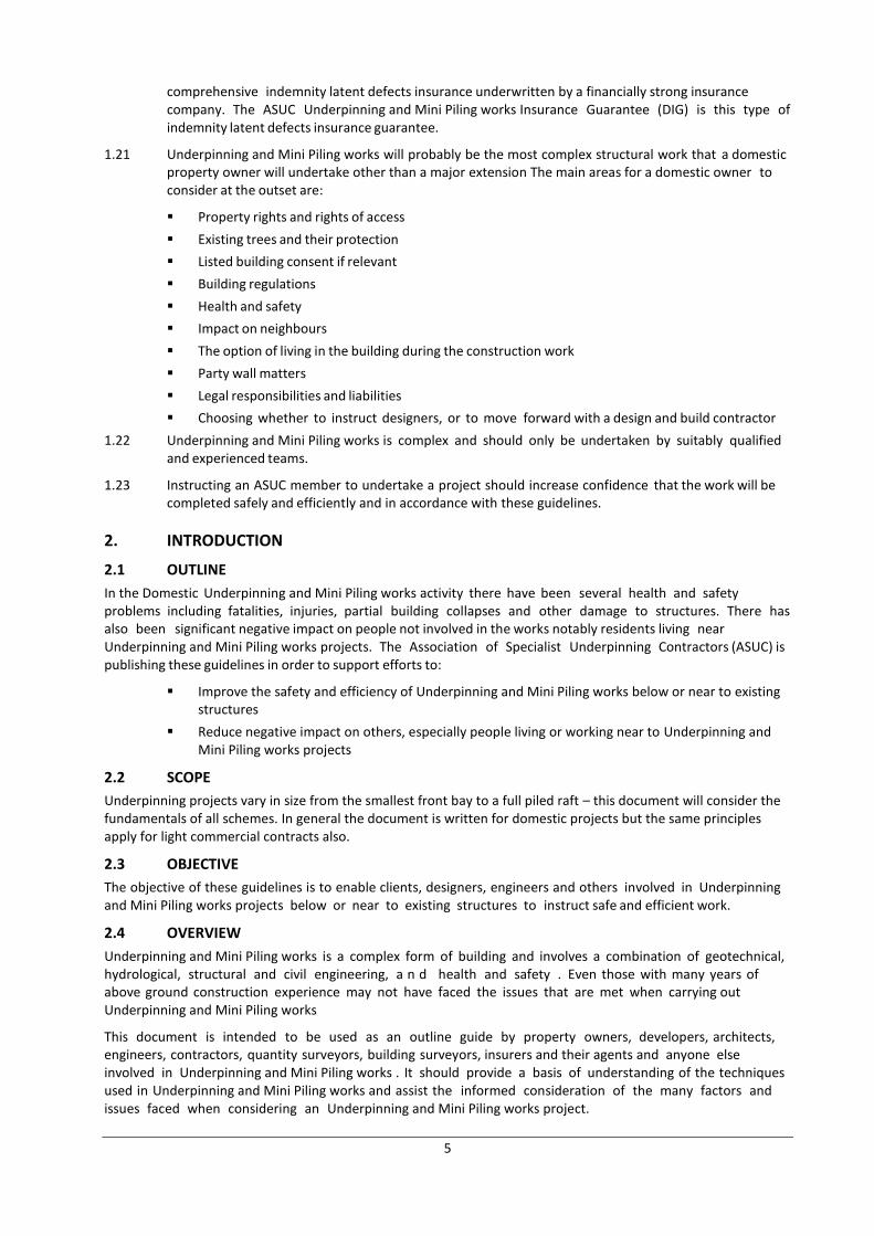
Underpinning and Mini Piling works will probably be the most complex structural work that a domestic 1.21property owner will undertake other than a major extension The main areas for a domestic owner to consider at the outset are:
Property rights and rights of access
Existing trees and their protection
Listed building consent if relevant
Building regulations
Health and safety
Impact on neighbours
The option of living in the building during the construction work
Party wall matters
Legal responsibilities and liabilities
Choosing whether to instruct designers, or to move forward with a design and build contractor
Underpinning and Mini Piling works is complex and should only be undertaken by suitably qualified 1.22and experienced teams.
Instructing an ASUC member to undertake a project should increase confidence that the work will be 1.23completed safely and efficiently and in accordance with these guidelines.
2. INTRODUCTION
2.1 OUTLINE
In the Domestic Underpinning and Mini Piling works activity there have been several health and safety problems including fatalities, injuries, partial building collapses and other damage to structures. There has also been significant negative impact on people not involved in the works notably residents living near Underpinning and Mini Piling works projects. The Association of Specialist Underpinning Contractors (ASUC) is publishing these guidelines in order to support efforts to:
Improve the safety and efficiency of Underpinning and Mini Piling works below or near to existing structures
Reduce negative impact on others, especially people living or working near to Underpinning and Mini Piling works projects
2.2 SCOPE
Underpinning projects vary in size from the smallest front bay to a full piled raft – this document will consider the fundamentals of all schemes. In general the document is written for domestic projects but the same principles apply for light commercial contracts also.
2.3 OBJECTIVE
The objective of these guidelines is to enable clients, designers, engineers and others involved in Underpinning and Mini Piling works projects below or near to existing structures to instruct safe and efficient work.
2.4 OVERVIEW
Underpinning and Mini Piling works is a complex form of building and involves a combination of geotechnical, hydrological, structural and civil engineering, a n d health and safety . Even those with many years of above ground construction experience may not have faced the issues that are met when carrying out Underpinning and Mini Piling works
This document is intended to be used as an outline guide by property owners, developers, architects, engineers, contractors, quantity surveyors, building surveyors, insurers and their agents and anyone else involved in Underpinning and Mini Piling works . It should provide a basis of understanding of the techniques used in Underpinning and Mini Piling works and assist the informed consideration of the many factors and issues faced when considering an Underpinning and Mini Piling works project.
6
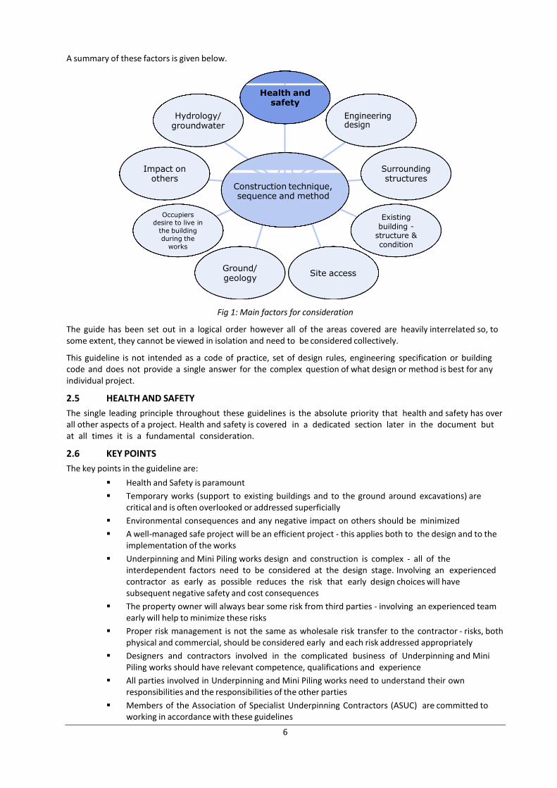
A summary of these factors is given below.
Fig 1: Main factors for consideration
The guide has been set out in a logical order however all of the areas covered are heavily interrelated so, to some extent, they cannot be viewed in isolation and need to be considered collectively.
This guideline is not intended as a code of practice, set of design rules, engineering specification or building code and does not provide a single answer for the complex question of what design or method is best for any individual project.
2.5 HEALTH AND SAFETY
The single leading principle throughout these guidelines is the absolute priority that health and safety has over all other aspects of a project. Health and safety is covered in a dedicated section later in the document but at all times it is a fundamental consideration.
2.6 KEY POINTS
The key points in the guideline are:
Health and Safety is paramount
Temporary works (support to existing buildings and to the ground around excavations) are critical and is often overlooked or addressed superficially
Environmental consequences and any negative impact on others should be minimized
A well-managed safe project will be an efficient project - this applies both to the design and to the implementation of the works
Underpinning and Mini Piling works design and construction is complex - all of the interdependent factors need to be considered at the design stage. Involving an experienced contractor as early as possible reduces the risk that early design choices will have subsequent negative safety and cost consequences
The property owner will always bear some risk from third parties - involving an experienced team early will help to minimize these risks
Proper risk management is not the same as wholesale risk transfer to the contractor - risks, both physical and commercial, should be considered early and each risk addressed appropriately
Designers and contractors involved in the complicated business of Underpinning and Mini Piling works should have relevant competence, qualifications and experience
All parties involved in Underpinning and Mini Piling works need to understand their own responsibilities and the responsibilities of the other parties
Members of the Association of Specialist Underpinning Contractors (ASUC) are committed to working in accordance with these guidelines
Health and safety
Hydrology/ groundwater
Impact on others
structures
Construction technique, sequence and method
Occupiers desire to live in
the building
during the
works
Existing
building - structure & condition
Ground/ geology
Site access
7
2.7 ASUC
ASUC (The Association of Specialist Underpinning Contractors) is a trade association founded in 1992 by a group of specialist contractors whose main business was foundation repair by underpinning and piling. The association's intention was to raise standards of health, safety and quality across the sector.
Standards in the foundation repair industry were improved by ASUC members being audited on health and safety, technical competence, financial strength and the completeness of their insurance cover. The increase in standards achieved by ASUC members enabled the association to introduce an insurance-backed latent defects guarantee scheme in 2002. This cover is provided by a major insurance company directly to the homeowner and covers any problem with the foundation repair work. An ASUC guarantee is now frequently demanded by insurers and other client as a prerequisite for foundation repair work.
2.8 SUMMARY
It is hoped that these guidelines will assist those involved in Underpinning and Mini Piling works to achieve the best possible outcome for their project with the work completed safely, efficiently and with the minimum negative impact on others.
In conclusion it is suggested that a property owner will increase the likelihood of achieving a safe and successful project by inviting an ASUC member, who will operate in line with the spirit of these guidelines, to be involved at the earliest opportunity.
3. DEFINITIONS
For the purposes of this document the terms listed below can be assumed to have the given meanings.
Anti-heave Precautions The use of materials which can compress, so as to absorb the pressures that may be exerted by the surrounding ground onto the elements of an underpinning system and adjoining structural elements.
Bases (or Piers ) Separate mass concrete blocks cast in excavations below an existing structure intended to support reinforced concrete underpinning beams.
Beams Reinforced concrete beams cast or placed within or under an existing wall or structure to carry the load from that wall or structure onto mass concrete bases, piles or pile-caps situated at intervals along the line of the existing wall etc.
Client This means any person or organisation for whom a project, which includes construction work, is carried out.
Contractor For the purposes of this document, ‘contractor’ means a member of the ASUC
Engineer A competent and qualified person in Structural or Civil Engineering tasked to provide calculations to support any scheme and to engineer a practical solution that a contractor can implement on site.
Competent A person or company can be regarded as being competent to undertake any particular job when they have gained sufficient qualifications, knowledge, experience and expertise to be able to do it efficiently and safely with a minimum degree of waste. In being so competent they will be able to recognise foreseeable difficulties, dangers or problems involved in undertaking their own specialist underpinning operation and will be able to plan, instigate, monitor and review all control measures necessary for dealing with the risks associated with the work.
Dry-pack A mixture of sharp sand and cement well rammed or compacted while in a semi-dry or moist state into a confined gap or space.
Mini piling Use of small diameter precast or cast insitu piles (when compared to typical heavy piles) which are jacked, augured driven or drilled. Typically mini piles or micro piles are defined as up to 350mm diameter and installed using a restricted access or headroom rig with auger sections of 1.2m.
Needles Inserts into a structure or material against which props or jacks may exert thrust in order to support the load of that structure or material.
8
Pins or Bases Mass concrete bases cast in excavated bays in a sequenced underpinning operation.
Reinforced Concrete Underpinning Creation of a stable foundation below an existing building or structure by the sequenced construction of reinforced concrete bases to create the new basement perimeter walling.
Traditional Underpinning The creation of a stable foundation below an existing building or structure by the sequenced construction of mass concrete bases to provide continuous support along the affected section.
Waste The loss, or unnecessary deployment of, labour, plant or materials. This definition includes losses through injuries because of lost time, disrupted works programme, remedial measures and administrative work by managers and supervisors.
Design In relation to any structure this includes drawings, details, specification and bills of quantities which relate to that structure. Refer to C.D.M. Regulations – see Annex E
Construction Phase Health and Safety Plan A plan which sets out the arrangements that will be made by the Principal Contractor to successfully manage the construction phase of any project..
4. TYPES OF UNDERPINNING AND MINI PILING
Underpinning and Mini Piling works types can be classified in multiple ways. In these guidelines the following classification will be used:
Mini piling
Mass concrete
Piles and beams
Piled rafts
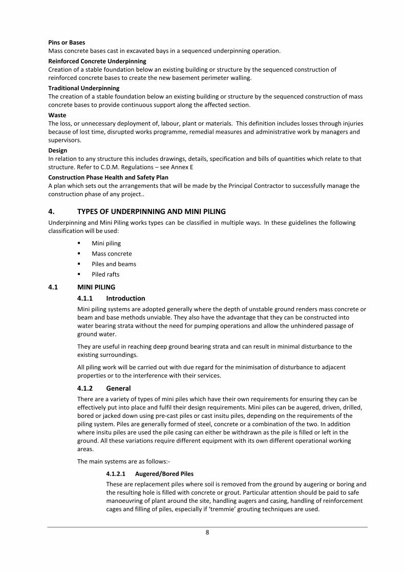
4.1 MINI PILING
4.1.1 Introduction
Mini piling systems are adopted generally where the depth of unstable ground renders mass concrete or beam and base methods unviable. They also have the advantage that they can be constructed into water bearing strata without the need for pumping operations and allow the unhindered passage of ground water.
They are useful in reaching deep ground bearing strata and can result in minimal disturbance to the existing surroundings.
All piling work will be carried out with due regard for the minimisation of disturbance to adjacent properties or to the interference with their services.
4.1.2 General
There are a variety of types of mini piles which have their own requirements for ensuring they can be effectively put into place and fulfil their design requirements. Mini piles can be augered, driven, drilled, bored or jacked down using pre-cast piles or cast insitu piles, depending on the requirements of the piling system. Piles are generally formed of steel, concrete or a combination of the two. In addition where insitu piles are used the pile casing can either be withdrawn as the pile is filled or left in the ground. All these variations require different equipment with its own different operational working areas.
The main systems are as follows:-
4.1.2.1 Augered/Bored Piles
These are replacement piles where soil is removed from the ground by augering or boring and the resulting hole is filled with concrete or grout. Particular attention should be paid to safe manoeuvring of plant around the site, handling augers and casing, handling of reinforcement cages and filling of piles, especially if ‘tremmie’ grouting techniques are used.
9
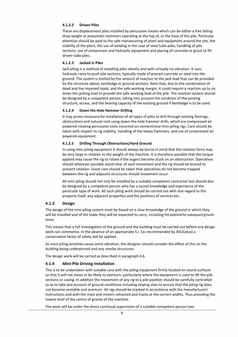
4.1.2.2 Driven Piles
These are displacement piles installed by percussive means which can be either a free falling drop weight or pneumatic hammers operating at the top of, or the base of the pile. Particular attention should be paid to the safe manoeuvring of plant and equipment around the site, the stability of the plant, the use of welding in the case of steel tube piles, handling of pile sections, use of compressor and hydraulic equipment and placing of concrete or grout to fill driven tube piles.
4.1.2.3 Jacked in Piles
Jack piling is a method of installing piles silently and with virtually no vibration. It uses hydraulic rams to push pile sections, typically made of precast concrete or steel into the ground. The system is limited by the amount of reaction to the jack load that can be provided by the structure above, kentledge or ground anchors. Note that, due to the combination of dead and live imposed loads, and the safe working margin, it could require a reaction up to six times the jacking load to provide the safe working load of the pile. The reaction system should be designed by a competent person, taking into account the condition of the existing structure, access, and the bearing capacity of the existing ground if kentledge is to be used.
4.1.2.4 Down the Hole Hammer Drilling
It may prove necessary for installation of all types of piles to drill through existing footings, obstructions and natural rock using down-the-hole hammer drills, which are compressed air powered rotating percussive tools mounted on conventional mini-piling rigs. Care should be taken with respect to rig stability, handling of the heavy hammers, and use of compressed air powered equipment.
4.1.2.5 Drilling Through Obstructions/Hard Ground
In using mini-piling equipment it should always be borne in mind that the rotation force may be very large in relation to the weight of the machine. It is therefore possible that the torque applied may cause the rig to rotate if the augers become stuck on an obstruction. Operatives should wherever possible stand clear of such movement and the rig should be braced to prevent rotation. Great care should be taken that operatives do not become trapped between the rig and adjacent structures should movement occur.
All mini piling should not only be installed by a suitably competent contractor but should also be designed by a competent person who has a sound knowledge and experience of the particular type of work. All such piling work should be carried out with due regard to the property itself, any adjacent properties and the positions of services etc.
4.1.3 Design
The design of the mini piling system must be based on a clear knowledge of the ground in which they will be installed and of the loads they will be expected to carry, including the potential for subsequent ground heave.
This means that a full investigation of the ground and the building must be carried out before any design work can commence. In the absence of an appropriate S.I. (as recommended by ASUCplus) a conservative factor of safety will be applied.
As most piling activities cause some vibration, the designer should consider the effect of this on the building being underpinned and any nearby structures.
The design work will be carried as described in paragraph 6.6.
4.1.4 Mini-Pile Driving Installation
This is to be undertaken with suitable care with the piling equipment firmly located on sound surfaces so that it will not move or be likely to overturn, particularly where the equipment is used to lift the pile sections or casing. In addition the movement of any rig to a pile position should be carefully controlled so as to take due account of ground conditions including sloping sites to ensure that the piling rig does not become unstable and overturn. All rigs should be tracked in accordance with the manufacturers’ instructions and with the mast and motors retracted and tracks at the correct widths. Thus providing the lowest level of the centre of gravity of the machine.
The work will be under the direct continual supervision of a suitable competent person (see
10
‘Definitions’), who will be supported by someone with suitable engineering knowledge.
There will be sufficient members in the piling crew to be able to do the work effectively, efficiently and safely, including such persons necessary to act as sentries or banks men etc.
4.1.5 Location of the Piling Installation Equipment
Where ever possible the piling equipment will be located so as to allow good access around it, leaving room for any removal of spoil and for the easy installation of piles, pile casing, reinforcement or concrete. The piling rig should be positioned on a firm well drained platform far enough from open excavations to avoid risk of collapse. Consideration should be given to noise, vibration and safety in relation to adjacent activities.
4.1.6 Setting Out
The piles will be carefully set out and checked to ensure that they have been driven or cast within specified tolerances. Where piles are outside this tolerance the design will either be revised to take their actual location into account or additional piles will be installed.
4.1.7 Handling Precast Piles and Pile Casings
Precast piles, pile sections and pile casings will be mechanically handled to comply with the Manual Lifting Operations Regulations, see paragraph 11.5.3. Where manual handling is unavoidable then the weight to be carried, the distance to be moved, and the awkwardness of the loads will be reflected in the number of persons carrying them.
4.1.8 Pile Installation to Achieve an Adequate Set or Load Bearing Properties
The piles will be installed to a set or level determined by the site investigation carried out before work commenced.
If it is found that either the set cannot be achieved or the ground conditions at the bottom of an augured hole are questionable then pile construction will cease until fresh instructions have been received from the Engineer.
4.1.9 Concreting Piles
Care will be taken to keep the pile bores clean and avoid the entry of foreign matter particularly when placing reinforcement. Where temporary casing is used, care will be taken to ensure that the bottom edge is never drawn above the level of the freshly placed concrete.
The concrete used should be a high slump mix suitable for placing without mechanical compaction.
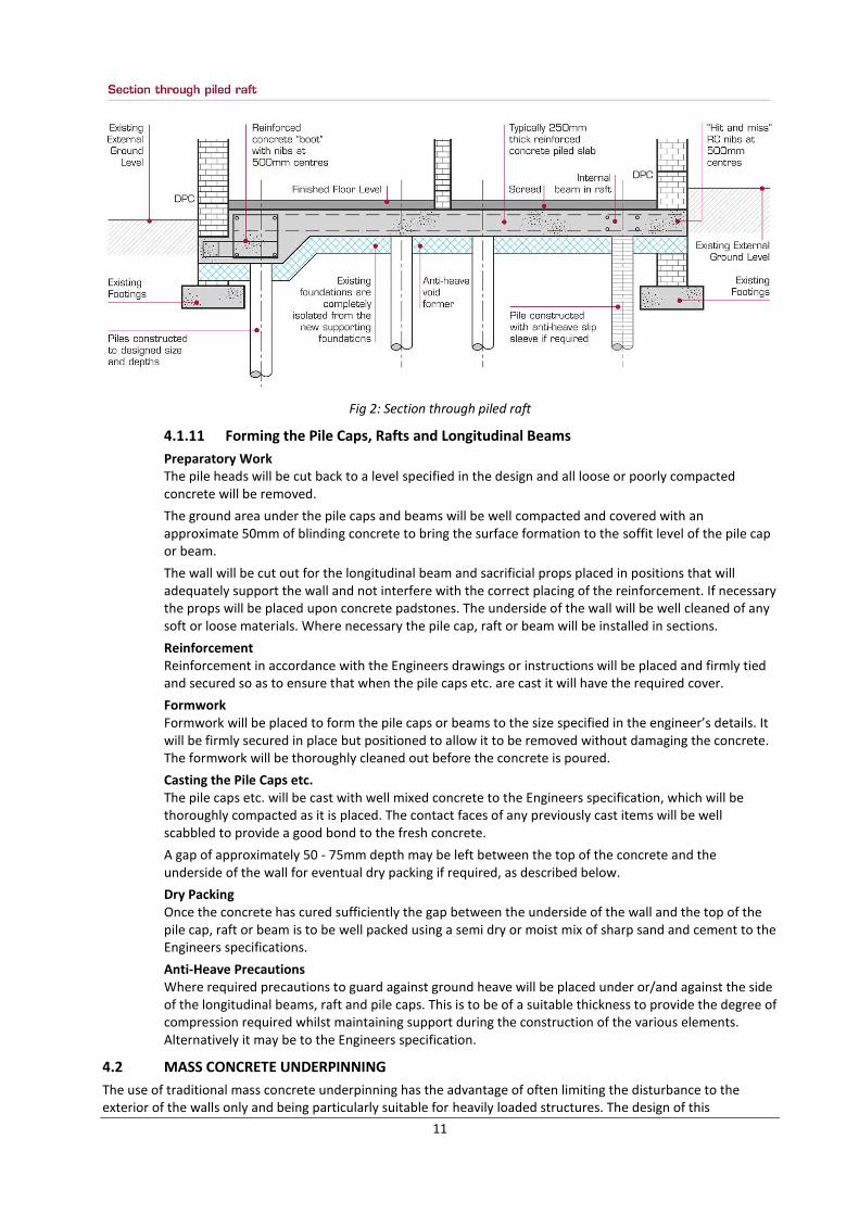
4.1.10 Pile Cap or Raft Construction
Mini piles are normally linked together by pile caps and beams or by a reinforced concrete raft.
They may be arranged in a number of ways. They may be constructed on one side of the wall only and the pile cap or raft cantilevered into or through the wall. Alternatively they may be arranged on either side of the wall and linked together by pile caps passing through it. Where necessary beams can then be constructed into the wall spanning between the pile caps.
When the complete building or a significant section of it is to be underpinned, a raft construction may be preferred. In this case the piles are all constructed inside the building and the reinforced concrete raft constructed over the piles with the raft needled into the external walls and supporting the internal walls.
11
Fig 2: Section through piled raft
4.1.11 Forming the Pile Caps, Rafts and Longitudinal Beams
Preparatory Work The pile heads will be cut back to a level specified in the design and all loose or poorly compacted concrete will be removed.
The ground area under the pile caps and beams will be well compacted and covered with an approximate 50mm of blinding concrete to bring the surface formation to the soffit level of the pile cap or beam.
The wall will be cut out for the longitudinal beam and sacrificial props placed in positions that will adequately support the wall and not interfere with the correct placing of the reinforcement. If necessary the props will be placed upon concrete padstones. The underside of the wall will be well cleaned of any soft or loose materials. Where necessary the pile cap, raft or beam will be installed in sections.
Reinforcement Reinforcement in accordance with the Engineers drawings or instructions will be placed and firmly tied and secured so as to ensure that when the pile caps etc. are cast it will have the required cover.
Formwork Formwork will be placed to form the pile caps or beams to the size specified in the engineer’s details. It will be firmly secured in place but positioned to allow it to be removed without damaging the concrete. The formwork will be thoroughly cleaned out before the concrete is poured.
Casting the Pile Caps etc. The pile caps etc. will be cast with well mixed concrete to the Engineers specification, which will be thoroughly compacted as it is placed. The contact faces of any previously cast items will be well scabbled to provide a good bond to the fresh concrete.
A gap of approximately 50 - 75mm depth may be left between the top of the concrete and the underside of the wall for eventual dry packing if required, as described below.
Dry Packing Once the concrete has cured sufficiently the gap between the underside of the wall and the top of the pile cap, raft or beam is to be well packed using a semi dry or moist mix of sharp sand and cement to the Engineers specifications.
Anti-Heave Precautions Where required precautions to guard against ground heave will be placed under or/and against the side of the longitudinal beams, raft and pile caps. This is to be of a suitable thickness to provide the degree of compression required whilst maintaining support during the construction of the various elements. Alternatively it may be to the Engineers specification.
4.2 MASS CONCRETE UNDERPINNING
The use of traditional mass concrete underpinning has the advantage of often limiting the disturbance to the exterior of the walls only and being particularly suitable for heavily loaded structures. The design of this
12
application is simple and it is quite cost-effective for shallow depths. It gives continuous support to the structure above and is useful when underpinning complicated wall plan layouts. Finally it is a process that allows the close inspection of the sub soil during construction, giving a confidence that the final construction will be effective due to the ability to amend construction details very easily.
4.2.1 General
The ground should be prepared to ensure that the pins are of the minimum width described in the specification or drawings and are adequately keyed into each other.
Whilst in most cases it is of little importance if they are oversized or have uneven sides, such defects are a waste of concrete and cannot be accepted where the work is exposed.
4.2.2 Excavate In A Planned Sequence
The specified sequence for the excavation of the pins will be followed. This sequence will reduce any movement or settlement in the structure being supported to a minimum.
4.2.2.1 Excavate Adjacent Pins
At the point where adjacent pins are to be constructed, all loose material on the exposed face of the adjoining pin will be cleaned off to ensure a good bond.
4.2.2.2 Cleaning the Underside of Existing Footings
Once exposed the underside of existing walls or footings will be cleaned of all debris or loose materials, including any defective parts of the existing walls etc., to ensure a proper transfer of load onto the underpinning.
4.2.3 Placing and Compacting
Prior to placing the concrete the area will be well cleaned of debris and earth. The sides of adjoining pins will be cleaned of all loose material and well keyed to ensure a good bond.
Concrete will be well mixed, well compacted and accurately placed. Care will be taken to ensure that all the corners in the excavated area are well filled with compacted concrete. In order to ensure proper compaction, the concrete will be placed in layers with each layer properly compacted before placing the next layer. Unnecessary delays between the placing of layers will be avoided. Should such delays occur, the lower layer would be keyed to ensure a good bond.
4.2.3.1 Mixing
Concrete will be sufficiently mixed to ensure an even distribution of its components within the mix to the design specification.
It will be placed as soon as is reasonably practicable after mixing and immediately compacted and finished off.
4.2.3.2 Formwork
Formwork will be fixed to form the sides of the pin to the size specified in the engineer’s details. It will be firmly secured but positioned to allow it to be removed without causing damage to the concrete.
4.2.3.3 Dry Packing
Once the concrete has cured sufficiently, the 75mm maximum gap between the underside of the wall or foundation and the top of the base are to be well packed using semi-dry or moist mix of sharp sand and cement. This will be done in accordance with the Engineers specifications.
4.2.3.4 Anti Heave Precautions
Where required anti heave materials will be placed against the side of the underpinning bases. This is to be of such a nature and thickness as to comply with the Engineers specification.
4.3 CONCRETE BEAM AND BASE
This type of work is quite adaptable and can be relatively easily fitted around existing services. It does not form a continuous barrier against the passage of ground water. It also allows for the inspection of the soil sub-strata insitu and can be relatively cost effective for deep underpinning operations.
13
It consists of individual concrete bases linked by a continuous beam supporting the walls. The beams can be installed, above, below or instead of the existing foundations.
Sections 1 – 14 and 21 of these guidelines also apply to this section.
4.3.1 GENERAL
This work will be preceded by the design of the concrete beams and planning of the positioning of the concrete bases. The bases or pins will normally be positioned under the points of maximum load or, where the distance between these points is excessive, at intermediate points between them although the location of services or other features may influence their location.
4.3.2 FORMING OF THE CONCRETE BASES
The bases or pins will be constructed in the sequence described in the drawings and to the sizes required.
4.3.2.1 Preparation Work
The bases will be excavated to the level specified by the Engineer in charge of the work. Following the Engineers’ inspection and approval, the base area will be covered with concrete blinding of an approximate 50mm thickness if necessary.
Note in some cases the beams may be constructed before the bases.
4.3.2.2 Formwork
The sides of the base may be lined where necessary with permanent or temporary formwork. This will be arranged so as to prevent the leakage of fines from the concrete as it is compacted.
If any of the bases will eventually be exposed then at least these areas will be true and fair faced.
Formwork will be placed to form the base to the size specified in the Engineers’ details. It will be firmly secured but positioned to allow it to be removed without causing damage to the concrete.
4.3.2.3 Casting the Bases
Prior to placing the concrete the formwork will be well cleaned of debris and earth. The surfaces of any adjoining concrete (bases are sometimes constructed in sections) will be cleaned of all loose material and well keyed to ensure a good bond.
Concrete will be well mixed, well compacted and accurately placed. Care will be taken to ensure that all the corners in the excavated area are well filled with compacted concrete.
In order to ensure proper compaction, the concrete will be placed in layers with each layer properly compacted before placing the next layer. Unnecessary delays between the placing of layers will be avoided. Should such delays occur, the lower layer would be keyed to ensure a good bond.
4.3.3 FORMATION OF THE CONCRETE BEAM
The concrete beam will be cut into, installed below or replace the footing to the existing wall at the level specified by the Engineer.
Note that reinforced concrete beams may often also be used in combination with mini-piling to form an underpinning system.
This form of construction should be considered when underpinning very weak walls as the sacrificial props used may be placed very close to each other to ensure that no brickwork or stonework falls down between them.
When the beam is constructed as the first part of the underpinning system, it has the advantage that any loose elements, or load concentrations may be properly supported prior to excavation of the bases thus obviating the need for temporary needling or shoring.
4.3.3.1 Preparation Work
Where necessary the tops of the bases on which the beams will rest will be cleaned of all
14
loose material. If necessary the surface of the base will be cut to an appropriate level.
The underside of the wall or foundation will be cleaned of any loose, weak or organic material.
The ground on which the beam will rest will be made firm and, if necessary, covered with a layer of blinding concrete up to the soffit level of the beam.
All loose debris and earth will be removed.
Sacrificial Props (or sometimes known as stools) These will be placed under the wall as it is cut out, under the line of thrust, usually centrally where they can best support the applied loads, aligned for easy installation of the reinforcement. Ensure that fixing the reinforcement does not disturb the props. This may require the specification of smaller diameter more flexible reinforcement bars . It is recommended that the maximum distance between props is 900mm centre to centre in brickwork with a 700mm clear span. Closer spacings are recommended for loose brickwork or loosely bonded masonry
They will be of a nature that will not deteriorate to any significant extent, e.g. steel or concrete. When necessary they will be placed on concrete padstones.
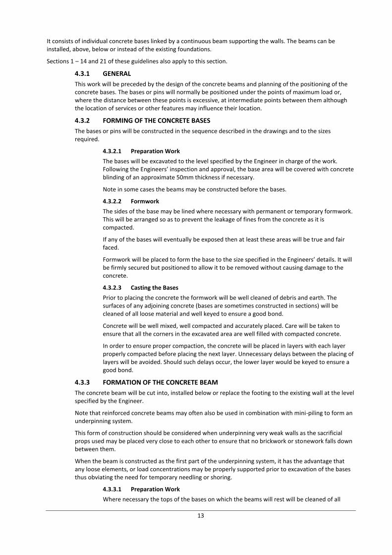
Beam Reinforcement Reinforcement in accordance with the Engineers’ drawings or instructions will be placed and firmly tied and secured so as to ensure that when the beam is cast it will have the required cover
Fig 3: Beam Reinforcement
Formwork Formwork will be placed to form the beam to the size specified in the Engineers’ details. It will be firmly secured in place but positioned to allow it to be removed without causing damage to the concrete.
Concrete The concrete may be poured to form the beam using chutes at 2m intervals and well compacted. Care will be taken to ensure that all corners of the beam are well filled with concrete and that it properly surrounds all reinforcement.
Dry Pack Once the longitudinal beam has cured sufficiently the gap between the underside of the wall and the top of the beam are to be well packed by a semi-dry or moist mix of sharp sand and cement to the Engineers specifications.
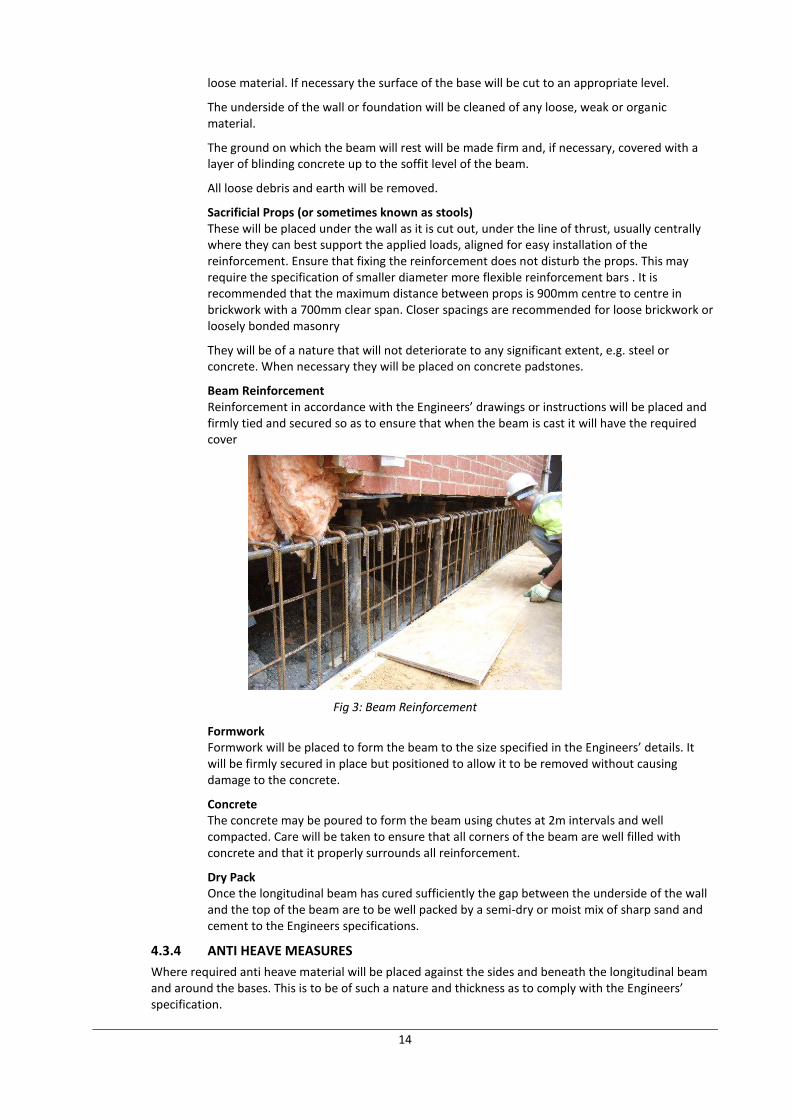
4.3.4 ANTI HEAVE MEASURES
Where required anti heave material will be placed against the sides and beneath the longitudinal beam and around the bases. This is to be of such a nature and thickness as to comply with the Engineers’ specification.
15
Fig 4: Anti Heave Measures
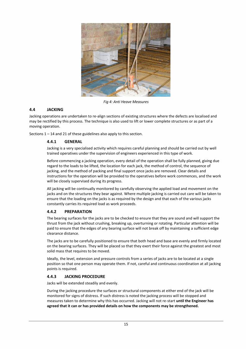
4.4 JACKING
Jacking operations are undertaken to re-align sections of existing structures where the defects are localised and may be rectified by this process. The technique is also used to lift or lower complete structures or as part of a moving operation.
Sections 1 – 14 and 21 of these guidelines also apply to this section.
4.4.1 GENERAL
Jacking is a very specialised activity which requires careful planning and should be carried out by well trained operatives under the supervision of engineers experienced in this type of work.
Before commencing a jacking operation, every detail of the operation shall be fully planned, giving due regard to the loads to be lifted, the location for each jack, the method of control, the sequence of jacking, and the method of packing and final support once jacks are removed. Clear details and instructions for the operation will be provided to the operatives before work commences, and the work will be closely supervised during its progress.
All jacking will be continually monitored by carefully observing the applied load and movement on the jacks and on the structures they bear against. Where multiple jacking is carried out care will be taken to ensure that the loading on the jacks is as required by the design and that each of the various jacks constantly carries its required load as work proceeds.
4.4.2 PREPARATION
The bearing surfaces for the jacks are to be checked to ensure that they are sound and will support the thrust from the jack without crushing, breaking up, overturning or rotating. Particular attention will be paid to ensure that the edges of any bearing surface will not break off by maintaining a sufficient edge clearance distance.
The jacks are to be carefully positioned to ensure that both head and base are evenly and firmly located on the bearing surfaces. They will be placed so that they exert their force against the greatest and most solid mass that requires to be moved.
Ideally, the level, extension and pressure controls from a series of jacks are to be located at a single position so that one person may operate them. If not, careful and continuous coordination at all jacking points is required.
4.4.3 JACKING PROCEDURE
Jacks will be extended steadily and evenly.
During the jacking procedure the surfaces or structural components at either end of the jack will be monitored for signs of distress. If such distress is noted the jacking process will be stopped and measures taken to determine why this has occurred. Jacking will not re-start until the Engineer has agreed that it can or has provided details on how the components may be strengthened.
16
4.4.3.1 Jack Selection
Jacks may be of screw-type, which usually have capacity limited to a few tonnes, or may be hydraulic which may have very high capacity usually between 10 and 50 Tonnes working load. Jack capacity should generally be double the calculated load if jacking is to proceed smoothly because load distribution varies during the jacking operation due to the stiffness of the structure. This is particularly relevant in brickwork.
Consideration should be given to the strength of the threads of screw jacks. Although hydraulic jacks rarely fail, such failures are usually due to leakages caused by seal failure, burst hoses, failure of a non-return valve or by over- extension. When lifting buildings, it is advisable to select jacks with threaded rams and safety collars which should be kept screwed down close to the body of the jack as lifting proceeds. Hydraulic jacks are designed for a maximum working oil pressure and pressure gauge.
4.4.3.2 Jack Extension
Jacks will only be extended within the range that enables them to carry the specified loads. It is advisable that the extension limit of a jack is clearly marked to ensure that it is not over extended during use. When lifting buildings, it is advisable to select hydraulic jacks with threaded rams and safety collars, which should be kept screwed down close to the body of the jack as lifting proceeds
4.4.3.3 Repositioning Jacks
Where jacks have to be repositioned, particularly if their extension is insufficient, then they will be relocated on firm, solid packing or bedding.
While the jacks are being repositioned, temporary or permanent props will be installed sufficient to support any loads that might be applied.
4.4.4 PACKING
During the course of the jacking operation, it may be necessary to reposition jacks to allow further re-levelling or increase the height of the lift. In this case, packing must be introduced in order to avoid failure. Such packing may consist of steel plates or concrete slabs beneath the jacks, and it may also be necessary to pack beside the jacks, possibly using blocks and folding wedges. Alternatively, jacks may be used in pairs, in which case either jack and its’ packing must be capable of safely supporting the full load at that position.
Following completion of the jacking operation, the load must be transferred back to the new or original foundation. This will normally be achieved by using concrete, brickwork, or for narrow gaps, semi dry concrete or mortar filling.
4.5 BASEMENT CONSTRUCTION
Basement construction is dealt with in a separate ASUC document entitled “Guidelines on safe and efficient basement construction directly below or near to existing structures” available from ASUC or download from www.asuc.org.uk
5. TECHNIQUES USED IN UNDERPINNING AND MINI PILING WORKS
5.1 INTRODUCTION
This section describes techniques used to build the main structural elements of underpinning
The main techniques covered are:
Underpinning
Piling
An additional section outlining the challenges faced when building below the groundwater level is also included.
5.2 UNDERPINNING
5.2.1 General
Underpinning is the technique by which an existing foundation is provided with increased depth. Historically this technique was used for foundation repair and strengthening.
17
Underpinning relies on the ability of a wall to span unsupported for a short length. This allows a section of wall to be undermined and a new structure to be built directly underneath. In this way new sections of lower level Underpinning and Mini Piling works foundation and wall can be built in a sequence until the existing wall is supported for its full length.
There are several types of underpinning used in Underpinning and Mini Piling works, each of which will be covered further in this section. At the broadest level they can be considered as either:
Mass concrete underpins - they are constructed of concrete and do not contain significant steel reinforcement. Structurally they can be considered as being made only of concrete.
Reinforced concrete (RC) underpins - these contain steel reinforcement that is designed to work structurally.
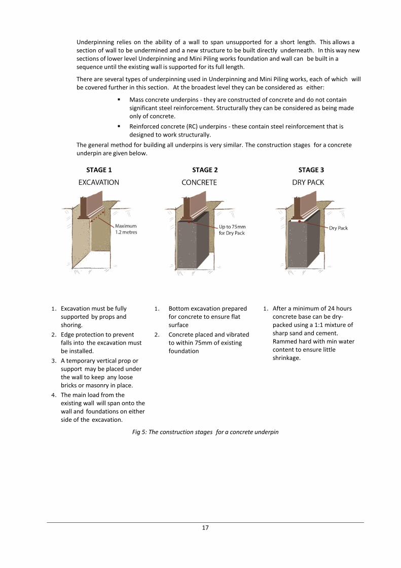
The general method for building all underpins is very similar. The construction stages for a concrete underpin are given below.
STAGE 1 STAGE 2 STAGE 3
1. Excavation must be fully supported by props and shoring.
2. Edge protection to prevent falls into the excavation must be installed.
3. A temporary vertical prop or support may be placed under the wall to keep any loose bricks or masonry in place.
4. The main load from the existing wall will span onto the wall and foundations on either side of the excavation.
1. Bottom excavation prepared for concrete to ensure flat surface
2. Concrete placed and vibrated to within 75mm of existing foundation
1. After a minimum of 24 hours concrete base can be dry-packed using a 1:1 mixture of sharp sand and cement. Rammed hard with min water content to ensure little shrinkage.
Fig 5: The construction stages for a concrete underpin
18
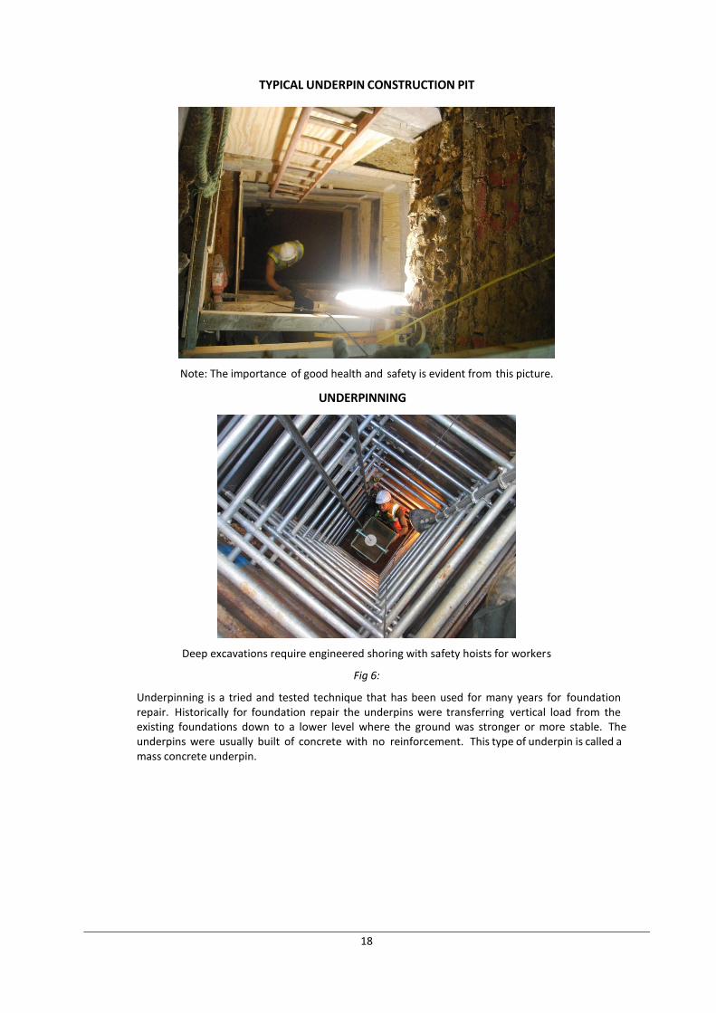
TYPICAL UNDERPIN CONSTRUCTION PIT
Note: The importance of good health and safety is evident from this picture.
UNDERPINNING
Deep excavations require engineered shoring with safety hoists for workers
Fig 6:
Underpinning is a tried and tested technique that has been used for many years for foundation repair. Historically for foundation repair the underpins were transferring vertical load from the existing foundations down to a lower level where the ground was stronger or more stable. The underpins were usually built of concrete with no reinforcement. This type of underpin is called a mass concrete underpin.
19
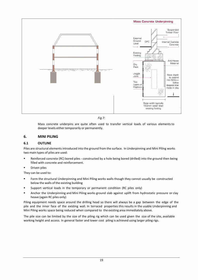
Fig 7:
Mass concrete underpins are quite often used to transfer vertical loads of various elements to deeper levels either temporarily or permanently.
6. MINI PILING
6.1 OUTLINE
Piles are structural elements introduced into the ground from the surface. In Underpinning and Mini Piling works two main types of piles are used:
Reinforced concrete (RC) bored piles - constructed by a hole being bored (drilled) into the ground then being filled with concrete and reinforcement.
Driven piles
They can be used to:
Form the structural Underpinning and Mini Piling works walls though they cannot usually be constructed below the walls of the existing building
Support vertical loads in the temporary or permanent condition (RC piles only)
Anchor the Underpinning and Mini Piling works ground slab against uplift from hydrostatic pressure or clay heave (again RC piles only)
Piling equipment needs space around the drilling head so there will always be a gap between the edge of the pile and the inner face of the existing wall. In terraced properties this results in the usable Underpinning and Mini Piling works space being reduced when compared to the existing area immediately above.
The pile size can be limited by the size of the piling rig which can be used given the size of the site, available working height and access. In general faster and lower cost piling is achieved using larger piling rigs.
20
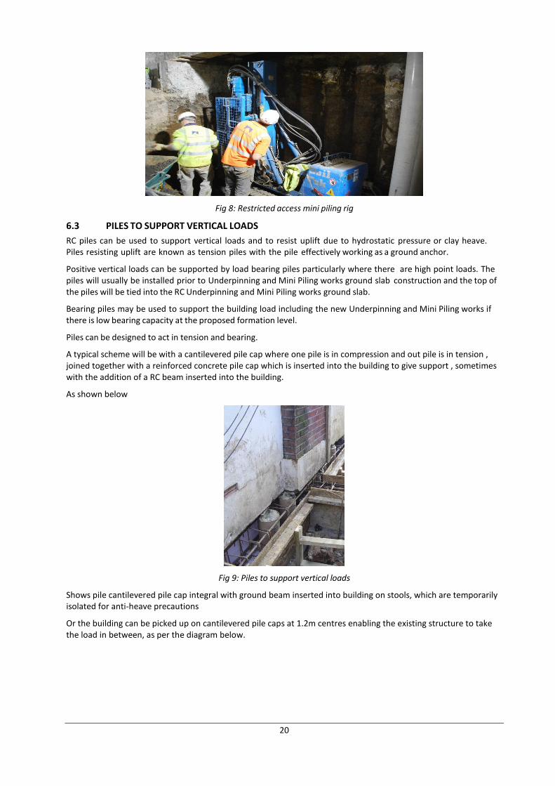
Fig 8: Restricted access mini piling rig
6.3 PILES TO SUPPORT VERTICAL LOADS
RC piles can be used to support vertical loads and to resist uplift due to hydrostatic pressure or clay heave. Piles resisting uplift are known as tension piles with the pile effectively working as a ground anchor.
Positive vertical loads can be supported by load bearing piles particularly where there are high point loads. The piles will usually be installed prior to Underpinning and Mini Piling works ground slab construction and the top of the piles will be tied into the RC Underpinning and Mini Piling works ground slab.
Bearing piles may be used to support the building load including the new Underpinning and Mini Piling works if there is low bearing capacity at the proposed formation level.
Piles can be designed to act in tension and bearing.
A typical scheme will be with a cantilevered pile cap where one pile is in compression and out pile is in tension , joined together with a reinforced concrete pile cap which is inserted into the building to give support , sometimes with the addition of a RC beam inserted into the building.
As shown below
Fig 9: Piles to support vertical loads
Shows pile cantilevered pile cap integral with ground beam inserted into building on stools, which are temporarily isolated for anti-heave precautions
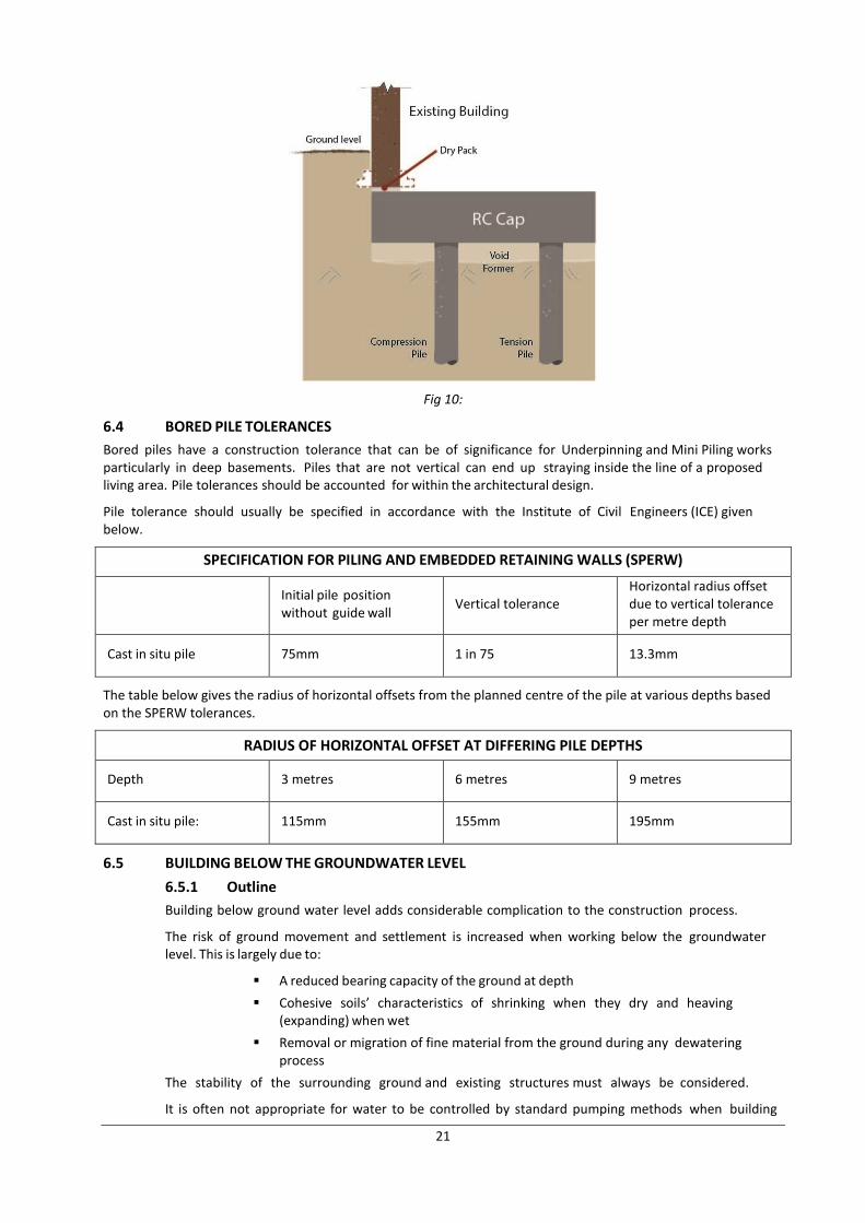
Or the building can be picked up on cantilevered pile caps at 1.2m centres enabling the existing structure to take the load in between, as per the diagram below.
21
Fig 10:
6.4 BORED PILE TOLERANCES
Bored piles have a construction tolerance that can be of significance for Underpinning and Mini Piling works particularly in deep basements. Piles that are not vertical can end up straying inside the line of a proposed living area. Pile tolerances should be accounted for within the architectural design.
Pile tolerance should usually be specified in accordance with the Institute of Civil Engineers (ICE) given below.
SPECIFICATION FOR PILING AND EMBEDDED RETAINING WALLS (SPERW)
Initial pile position without guide wall
Vertical tolerance Horizontal radius offset due to vertical tolerance per metre depth
Cast in situ pile 75mm 1 in 75 13.3mm
The table below gives the radius of horizontal offsets from the planned centre of the pile at various depths based on the SPERW tolerances.
RADIUS OF HORIZONTAL OFFSET AT DIFFERING PILE DEPTHS
Depth 3 metres 6 metres 9 metres
Cast in situ pile: 115mm 155mm 195mm
6.5 BUILDING BELOW THE GROUNDWATER LEVEL
6.5.1 Outline
Building below ground water level adds considerable complication to the construction process.
The risk of ground movement and settlement is increased when working below the groundwater level. This is largely due to:
A reduced bearing capacity of the ground at depth
Cohesive soils’ characteristics of shrinking when they dry and heaving (expanding) when wet
Removal or migration of fine material from the ground during any dewatering process
The stability of the surrounding ground and existing structures must always be considered.
It is often not appropriate for water to be controlled by standard pumping methods when building
22
below the groundwater level as these do not take account of the stability of the ground.
There are several techniques that have been developed specifically for construction of u n d e r p i n n i n g below the ground water level. Broadly these are:
Local lowering of the groundwater level.
Construction of a perimeter barrier to control water ingress.
Soil stabilisation.
Ground freezing is also a recognised technique to enable construction below the water table. It has the disadvantages of causing ground heave due to the expansion of the water and of the frozen ground being difficult to dig through. It is usually limited to large scale commercial projects due to cost and size of plant required. This technique will not be considered further.
6.5.2 Local lowering of the groundwater level
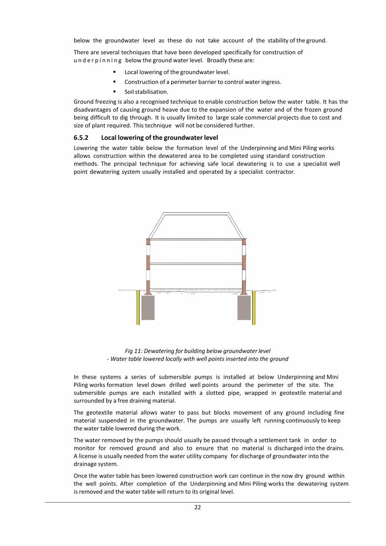
Lowering the water table below the formation level of the Underpinning and Mini Piling works allows construction within the dewatered area to be completed using standard construction methods. The principal technique for achieving safe local dewatering is to use a specialist well point dewatering system usually installed and operated by a specialist contractor.
Fig 11: Dewatering for building below groundwater level - Water table lowered locally with well points inserted into the ground
In these systems a series of submersible pumps is installed at below Underpinning and Mini Piling works formation level down drilled well points around the perimeter of the site. The submersible pumps are each installed with a slotted pipe, wrapped in geotextile material and surrounded by a free draining material.
The geotextile material allows water to pass but blocks movement of any ground including fine material suspended in the groundwater. The pumps are usually left running continuously to keep the water table lowered during the work.
The water removed by the pumps should usually be passed through a settlement tank in order to monitor for removed ground and also to ensure that no material is discharged into the drains. A license is usually needed from the water utility company for discharge of groundwater into the drainage system.
Once the water table has been lowered construction work can continue in the now dry ground within the well points. After completion of the Underpinning and Mini Piling works the dewatering system is removed and the water table will return to its original level.
23
Soil stabilisation involves changing the soil's natural properties by introducing material which mixes or binds the soil. The intention is both to block the flow of water and increase soil stability.
Soil stabilisation can be achieved in a number of ways from large scale compensation grouting to targeted lance injection.
Some soil stabilisation techniques that are widely used in conventional civil engineering can cause ground movement due to the pressure under which the stabilising material is introduced and can also require relatively large associated plant. Therefore these techniques are not usually suitable for Underpinning and Mini Piling works projects directly below or near to existing structures or on restricted sites.
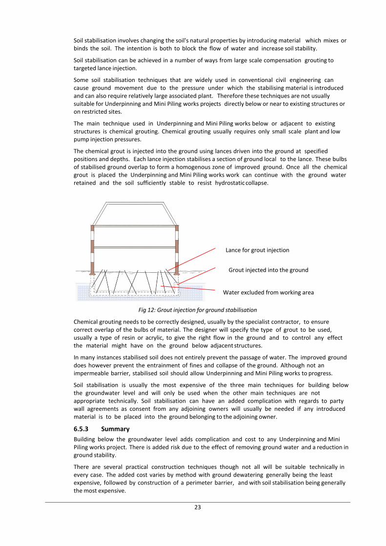
The main technique used in Underpinning and Mini Piling works below or adjacent to existing structures is chemical grouting. Chemical grouting usually requires only small scale plant and low pump injection pressures.
The chemical grout is injected into the ground using lances driven into the ground at specified positions and depths. Each lance injection stabilises a section of ground local to the lance. These bulbs of stabilised ground overlap to form a homogenous zone of improved ground. Once all the chemical grout is placed the Underpinning and Mini Piling works work can continue with the ground water retained and the soil sufficiently stable to resist hydrostatic collapse.
Fig 12: Grout injection for ground stabilisation
Chemical grouting needs to be correctly designed, usually by the specialist contractor, to ensure correct overlap of the bulbs of material. The designer will specify the type of grout to be used, usually a type of resin or acrylic, to give the right flow in the ground and to control any effect the material might have on the ground below adjacent structures.
In many instances stabilised soil does not entirely prevent the passage of water. The improved ground does however prevent the entrainment of fines and collapse of the ground. Although not an impermeable barrier, stabilised soil should allow Underpinning and Mini Piling works to progress.
Soil stabilisation is usually the most expensive of the three main techniques for building below the groundwater level and will only be used when the other main techniques are not appropriate technically. Soil stabilisation can have an added complication with regards to party wall agreements as consent from any adjoining owners will usually be needed if any introduced material is to be placed into the ground belonging to the adjoining owner.
6.5.3 Summary
Building below the groundwater level adds complication and cost to any Underpinning and Mini Piling works project. There is added risk due to the effect of removing ground water and a reduction in ground stability.
There are several practical construction techniques though not all will be suitable technically in every case. The added cost varies by method with ground dewatering generally being the least expensive, followed by construction of a perimeter barrier, and with soil stabilisation being generally the most expensive.
Lance for grout injection
Grout injected into the ground
Water excluded from working area
24
Input from geotechnical, engineering and Underpinning and Mini Piling works specialists should always be sought as early as possible if constructing an Underpinning and Mini Piling works below or near to existing structures below the groundwater level.
Also see section 7.5 re stabilisation and working within the water table
7. GROUND IMPROVEMENT
7.1 GENERAL
Ground improvement and Stabilisation works whilst not classed as underpinning form an important part of the tool box in dealing with Subsidence and other related issues . Please note that because of the nature of these improvement and stabilisation techniques the ASUC Defects Insurance Guarantee (DIG) is not available currently for this type of work
Typically they are ground improvement techniques using either Grout injection techniques with either cementitious or resin grouts.
This section will deal briefly with these methods of construction.
7.2 INTRODUCTION
The techniques of stabilising (increasing the strength or density) of the ground beneath a structure have improved over the past few years and are now used widely as an alternative method to underpinning the foundations of structures bearing onto non cohesive soils and fills.
There are a number of common causes of structural distress which can be treated using these techniques:-
Leaking drains washing away the fines from the bearing soil
Badly or insufficiently compacted non-cohesive fills
Compression of a fibrous peat layer at depth
Voids caused by the opening up of mine shafts and solution features such as swallow holes
Loss of slope stability
7.3 INCREASING THE STRENGTH OF THE SUPPORTING SOIL OR FILL
The physics behind this technique is to permeate the soil or fill beneath the foundations with a geotechnical grout to a sufficient depth to provide the building with a bearing medium strong enough to distribute the loads without further compression. The grout is delivered into the soil to the depth required normally using a tube system.
The principle of this system relies on the strata being sufficiently permeable to allow the grout to pass freely amongst the soil particles often taking the place of the water and air voids. The use of a Newtonian fluid grout rather than a particulate grout will ensure that even in fine or highly variable soils full p is achieved. Once the grout has set and cured the encapsulated soil particles are bonded together to form a concreted mass.
This technique is therefore not suitable for low and non-permeable soils such as clays and clayey silts or fills containing a high proportion of cohesive material.
The advantages of this system are:
No excavation beneath the footings is required
No spoil is removed from site
Rapid installation without major works
Can be carried out externally and internally
No heavy plant
Can be installed in very restricted areas and low headroom
The grout does not disturb sealed drains, ducts or buried services
Controlled volumes of grout are used to provide large diameter stabilised columns or piles up to 12m depth.
Low risks to operatives.
Schemes can be designed using established soil mechanics principles.
25
The disadvantage of this system:
Cannot be used in cohesive soils and fills
7.4 INCREASING THE DENSITY OF THE SUPPORTING SOIL OR FILL – COMPACTION GROUTING
The physics behind this technique is to force a grout into non cohesive soils or fills to compact them and fill voids. The resultant strata should be more tightly compacted and have a higher bearing capacity sufficient to support the building loads without further settlement.
Compaction grouting can use expanding geotechnical resins often polyurethane based or cementitious grouts where applicable. The delivery system is via tubes placed to the depth required and usually withdrawn in stages.
The advantages of Compaction Grouting
No excavation beneath the footings is required
No spoil is removed from site
Rapid installation without major works
Can be carried out externally and internally
No heavy plant
Can be installed in very restricted areas and headroom
When using expanding polyurethane grouts controlled uplift of footings can be achieved
Low risks to operatives
The disadvantages of Compaction Grouting
Cannot be used in cohesive soils and fills
Drain runs and ducts adjacent to and below the level of the original foundations can be affected by the pressures exerted as the resin expands.
Controlling the volumes of grout used and the direction of migration.
Risk of unwanted structural displacement and soil relaxation with time.
Important Information required for both techniques
Location of all services in the vicinity of the footings (adjacent and beneath)
Detailed soils data down to a suitable bearing strata including SPT ‘N’ value readings with depth, accurate descriptions and soil classification, sieve analysis if possible.
Accurate details of the existing foundation type, dimensions and load distribution.
Asbestos survey
Drain survey to identify location and faults
Definitions
* Newtonian Fluid – a fluid which does not change viscosity characteristics with changes in applied pressure (e.g. water)
** Particulate grout – a fluid grout containing particles (e.g. cement grout)
7.5 STABILISING OF NON- COHESIVE SOIL BELOW THE WATER TABLE
The practicalities of excavating safely for underpinning in non-cohesive deposits are exacerbated in cases where the required depth to formation level takes the specialist contractor below the water table. If localised pumping is attempted the resultant in-flow of water can bring with it the finer fractions of the deposit potentially giving rise to undermining or reduction in volume of surrounding ground which in turn can endanger footings and slabs.
If dewatering the site is not a practical or financial option there are techniques for grouting the soil to be excavated. The technique needs to be able to control the flow of water as well as allow safe excavation without the risk of collapse of the sides of the pit.
The principle of stabilising is to combine a grout with the granular deposit to produce a cemented soil which will be strong enough to be self-supporting over a limited height and prevent water movement into the excavation. By replacing the pore spaces with a solid matrix the permeability of the soil is significantly reduced whilst at the same time the solidifying grout binds the soil particles together to form a mass which can be safely excavated through using conventional underpinning tools.
Grouts used for stabilising include polyurethane, cement based slurries, sodium silicates and acrylic resin. Each
26
have merits depending upon the site circumstances and the type of grout and the technique for applying it into the ground need to be carefully assessed and designed by a specialist.
7.5.1 Geotechnical Grade Polyurethane
Advantages
Can be accurately injected at low pressure to permeate the soil
Low viscosity
Has controlled expansion to enhance soil penetration
Provides a cemented deposit which can be easily excavated conventionally
Prevents water passage through the cemented sections.
Can be applied using small hand held equipment
Most reliable in general use
Disadvantages
Expensive grout
7.5.2 Cement Based Grouts – combination of cement, fillers, plasticisers and water
Advantages
Cheap grout
Large volumes can easily be mixed and applied if required
Disadvantages
Large plant is required to drill, mix and inject the grout
It dilutes in water
High pressure usually required to overcome the filter effect of the deposit on the grout
Control of the grouted area and volume
The cured stabilised ground can be very strong
7.5.3 Sodium Silicates – a solution of sodium silicate diluted in water
Advantages
Cheap
Low viscosity
Can be pumped into suitable soils with small equipment
The consolidated deposit can easily be excavated
Disadvantages
Dilutes in water and can be displaced during the curing phase when injected in moving water.
Requires large volumes to ensure soil penetration.
The unknown resultant strength of the stabilised deposit.
7.5.4 Acrylic Grout – a solution of acrylic resin, accelerators and water
Advantages
Low viscosity
Can be pumped into suitable soils with small equipment
The consolidated deposit can easily be excavated
Disadvantages
Dilutes in water
Requires large volumes to ensure soil penetration
The unknown resultant strength of the stabilised deposit
Can have accelerated gel time under high pressure
27
7.6 WARRANTIES
Please note that because of the nature of these stabilisation techniques the ASUC Defects Insurance Guarantee (DIG) is not available currently for this type of work.
8. TEMPORARY WORKS
8.1 INTRODUCTION
Temporary works are the parts of the works that allow or enable construction of, protect, support or provide access to the permanent works. They might or might not remain in place at the completion of the works. Temporary works include horizontal support to excavations and part built permanent works, and vertical support to existing structures. Temporary works will often consist of proprietary propping systems such as Slimshore Soldiers or Maybey Props, and smaller scale Acrow props or timber shoring.
All Underpinning and Mini Piling works projects require temporary works. They are often complex with a mixture of horizontal and vertical temporary works in place at the same time and with different elements of the temporary works being installed, adjusted or removed concurrently.
A major cause of health and safety problems associated with Underpinning and Mini Piling works is poor temporary works especially horizontal temporary works supporting excavations and part built Underpinning and Mini Piling works structures. The temporary works on projects with problems are often:
Missing
Poorly or not designed
Installed incorrectly
Inadequate
Not controlled
Uncoordinated
Removed prematurely or out of sequence
Possibly the most critical factor in avoiding serious health and safety problems on Underpinning and Mini Piling works projects is the correct understanding of the function of the temporary works and how they should be installed.
Temporary works must be designed, installed, checked and supervised correctly. A sound process to ensure that nothing is missed must be in place.
8.2 TYPES
8.2.1 Outline
Temporary works in Underpinning and Mini Piling works c a n be divided into the following main areas:
Excavations - generally:
Individual underpin excavations
Structures - support to the existing building or adjoining buildings and to the permanent works in the temporary condition
Equipment and plant - equipment and plant that has been brought onto site as part of the works
Site facilities - hoarding and welfare facilities
8.2.2 Individual underpin excavations
The weight of the ground and of any loads surcharging the sides of an excavation make collapse or movement likely if adequate support is not provided.
Horizontal loads increase with depth so deeper excavations will need greater and more robust shoring than shallow excavations.
There are two aspects to be considered when shoring an underpin excavation.
Safety of the personnel involved in the excavation
The degree of relaxation of the ground that is permitted in relation to the potential
28
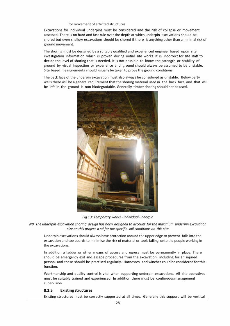
for movement of effected structures
Excavations for individual underpins must be considered and the risk of collapse or movement assessed. There is no hard and fast rule over the depth at which underpin excavations should be shored but even shallow excavations should be shored if there is anything other than a minimal risk of ground movement.
The shoring must be designed by a suitably qualified and experienced engineer based upon site investigation information which is proven during initial site works. It is incorrect for site staff to decide the level of shoring that is needed. It is not possible to know the strength or stability of ground by visual inspection or experience and ground should always be assumed to be unstable. Site based measurements should usually be taken to prove the ground conditions.
The back face of the underpin excavation must also always be considered as unstable. Below party walls there will be a general requirement that the shoring material used in the back face and that will be left in the ground is non-biodegradable. Generally timber shoring should not be used.
Fig 13: Temporary works - individual underpin
NB. The underpin excavation shoring design has been designed to account for the maximum underpin excavation size on this project a nd for the specific soil conditions on this site
Underpin excavations should always have protection around the upper edge to prevent falls into the excavation and toe boards to minimise the risk of material or tools falling onto the people working in the excavations.
In addition a ladder or other means of access and egress must be permanently in place. There should be emergency exit and escape procedures from the excavation, including for an injured person, and these should be practised regularly. Harnesses and winches could be considered for this function.
Workmanship and quality control is vital when supporting underpin excavations. All site operatives must be suitably trained and experienced. In addition there must be continuous management supervision.
8.2.3 Existing structures
Existing structures must be correctly supported at all times. Generally this support will be vertical
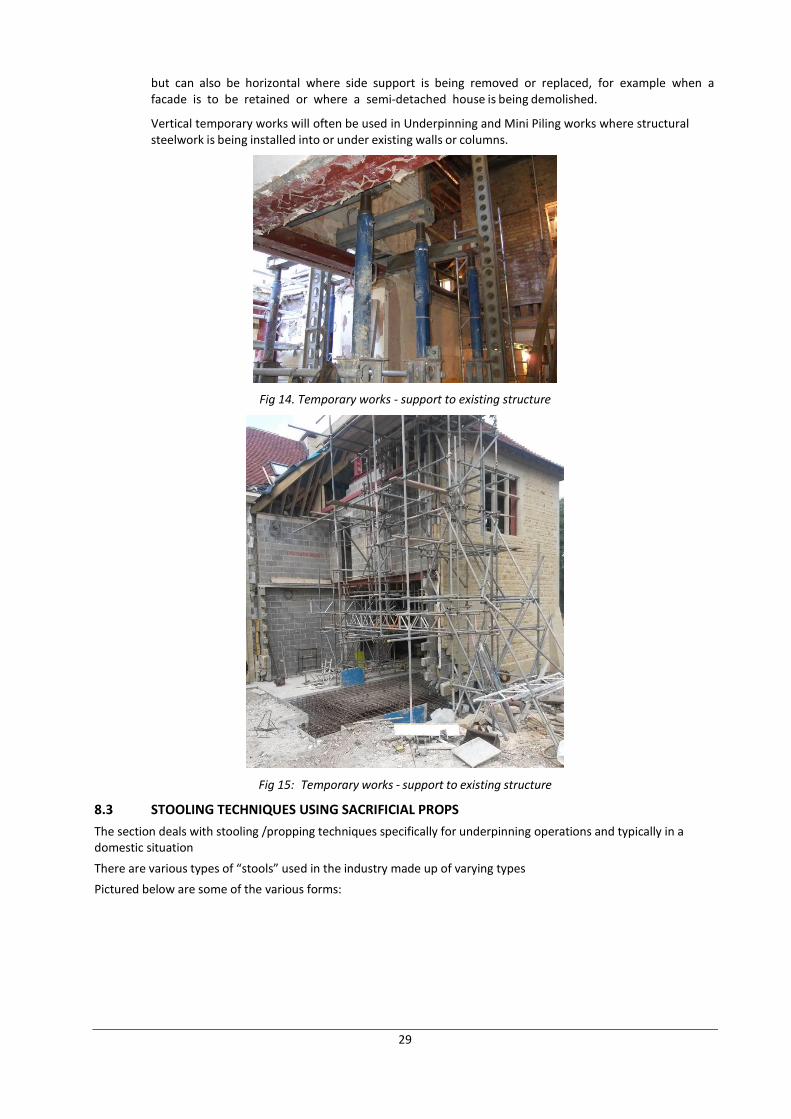
29
but can also be horizontal where side support is being removed or replaced, for example when a facade is to be retained or where a semi-detached house is being demolished.
Vertical temporary works will often be used in Underpinning and Mini Piling works where structural steelwork is being installed into or under existing walls or columns.
Fig 14. Temporary works - support to existing structure
Fig 15: Temporary works - support to existing structure
8.3 STOOLING TECHNIQUES USING SACRIFICIAL PROPS
The section deals with stooling /propping techniques specifically for underpinning operations and typically in a domestic situation
There are various types of “stools” used in the industry made up of varying types
Pictured below are some of the various forms:
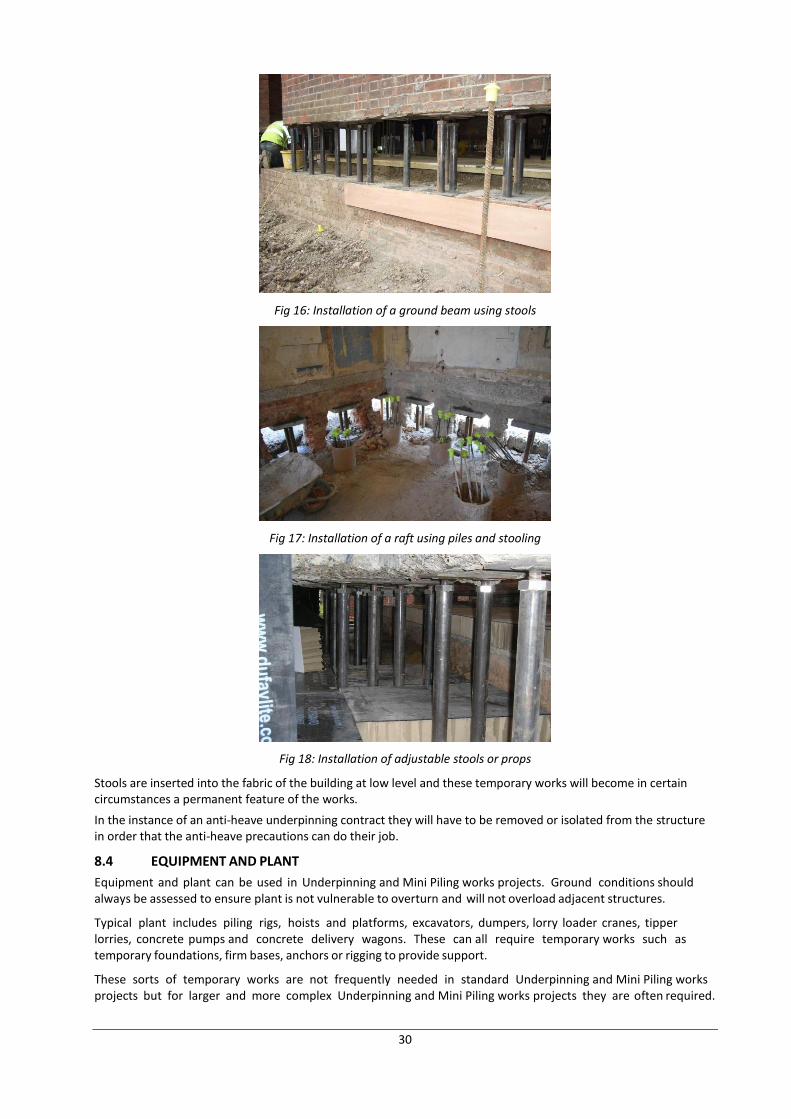
30
Fig 16: Installation of a ground beam using stools
Fig 17: Installation of a raft using piles and stooling
Fig 18: Installation of adjustable stools or props
Stools are inserted into the fabric of the building at low level and these temporary works will become in certain circumstances a permanent feature of the works.
In the instance of an anti-heave underpinning contract they will have to be removed or isolated from the structure in order that the anti-heave precautions can do their job.
8.4 EQUIPMENT AND PLANT
Equipment and plant can be used in Underpinning and Mini Piling works projects. Ground conditions should always be assessed to ensure plant is not vulnerable to overturn and will not overload adjacent structures.
Typical plant includes piling rigs, hoists and platforms, excavators, dumpers, lorry loader cranes, tipper lorries, concrete pumps and concrete delivery wagons. These can all require temporary works such as temporary foundations, firm bases, anchors or rigging to provide support.
These sorts of temporary works are not frequently needed in standard Underpinning and Mini Piling works projects but for larger and more complex Underpinning and Mini Piling works projects they are often required.
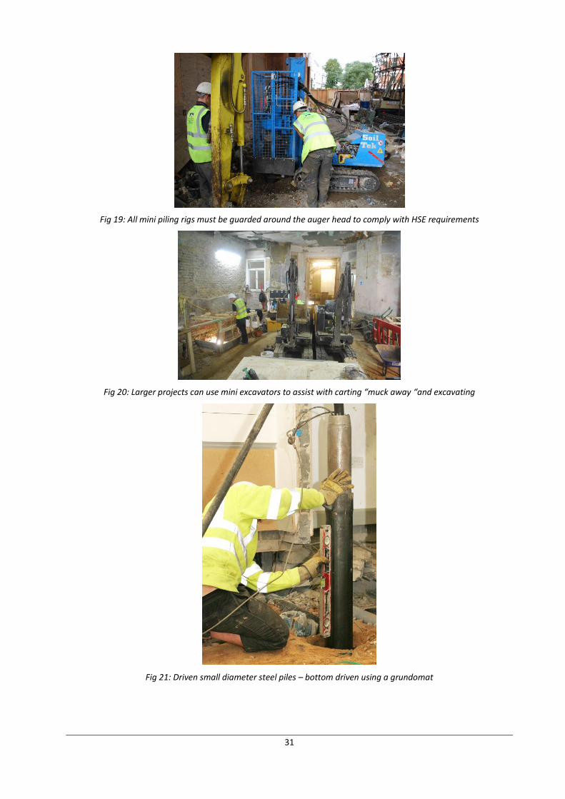
31
Fig 19: All mini piling rigs must be guarded around the auger head to comply with HSE requirements
Fig 20: Larger projects can use mini excavators to assist with carting “muck away “and excavating
Fig 21: Driven small diameter steel piles – bottom driven using a grundomat
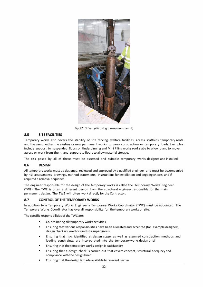
32
Fig 22: Driven pile using a drop hammer rig
8.5 SITE FACILITIES
Temporary works also covers the stability of site fencing, welfare facilities, access scaffolds, temporary roofs and the use of either the existing or new permanent works to carry construction or temporary loads. Examples include support to suspended floors or Underpinning and Mini Piling works roof slabs to allow plant to move across or work from them, and support to floors to allow material storage.
The risk posed by all of these must be assessed and suitable temporary works designed and installed.
8.6 DESIGN
All temporary works must be designed, reviewed and approved by a qualified engineer and must be accompanied by risk assessments, drawings, method statements, instructions for installation and ongoing checks, and if required a removal sequence.
The engineer responsible for the design of the temporary works is called the Temporary Works Engineer (TWE). The TWE is often a different person from the structural engineer responsible for the main permanent design. The TWE will often work directly for the Contractor.
8.7 CONTROL OF THE TEMPORARY WORKS
In addition to a Temporary Works Engineer a Temporary Works Coordinator (TWC) must be appointed. The Temporary Works Coordinator has overall responsibility for the temporary works on site.
The specific responsibilities of the TWC are:
Co-ordinating all temporary works activities
Ensuring that various responsibilities have been allocated and accepted (for example designers, design checkers, erectors and site supervisors)
Ensuring that risks identified at design stage, as well as assumed construction methods and loading constraints, are incorporated into the temporary works design brief
Ensuring that the temporary works design is satisfactory
Ensuring that a design check is carried out that covers concept, structural adequacy and compliance with the design brief
Ensuring that the design is made available to relevant parties
33
Maintaining a register or record of all drawings, calculations and other relevant documents relating to the final design
Ensuring that those responsible for on-site supervision receive full details of the design, including any limitations and guidance notes
Ensuring that risk assessments and guidance notes are prepared covering the safe erection and dismantling sequence
Making checks at appropriate stages during construction of temporary works
Issuing the permit to load after a final physical check
Monitoring and inspecting the temporary works while they are loaded
Ensuring that appropriate maintenance is carried out to temporary works for example to facade retention or vertical propping
Issuing formal permission to dismantle the temporary works and specify any relevant sequence once the permanent works have attained adequate strength
8.8 SUMMARY
The Health and Safety Executive report that a frequent cause of major structural failure with Underpinning and Mini Piling works projects is the failure of the contractor to appoint a Temporary Works Engineer and a Temporary Works Coordinator, relying instead on their own perceived experience and an ‘it’s always worked before’ mentality. In particular excavations must be correctly supported.
Contractors must appoint a Temporary Works Engineer and a Temporary Works Coordinator. The temporary works must be designed, installed, checked, monitored, coordinated and controlled correctly.
9. IMPACT ON OTHERS
9.1 INTRODUCTION
Underpinning and Mini Piling works can have a significant negative impact on neighbours, local residents, other road users and other members of the public. Minimising negative impact on others needs to be considered at an early stage in the project to avoid high impact methods being locked in by the design.
The main negative impacts on others are:
Damage to surrounding buildings and structures.
Noise, vibration and dust.
Traffic congestion.
Early communication and consultation with local residents will go some way to reduce negative construction impact.
9.2 DAMAGE TO SURROUNDING BUILDINGS AND STRUCTURES
9.2.1 Introduction
There will always be some risk of damage to surrounding buildings when any construction work takes place, be it Underpinning and Mini Piling works or above ground work. The risk of damage should always be minimised.
Underpinning and piling combined with appropriate temporary works, when correctly designed and installed, should minimise damage. In the majority of cases there should be no noticeable structural damage. Damage should usually be limited to superficial cosmetic damage. The table for categorisation of damage to buildings is at appendix B.
In nearly all cases where there is greater damage than this the root cause is either poor design or workmanship. Instructing a competent and experienced contractor is probably the most critical factor in avoiding damage to surrounding buildings and structures.
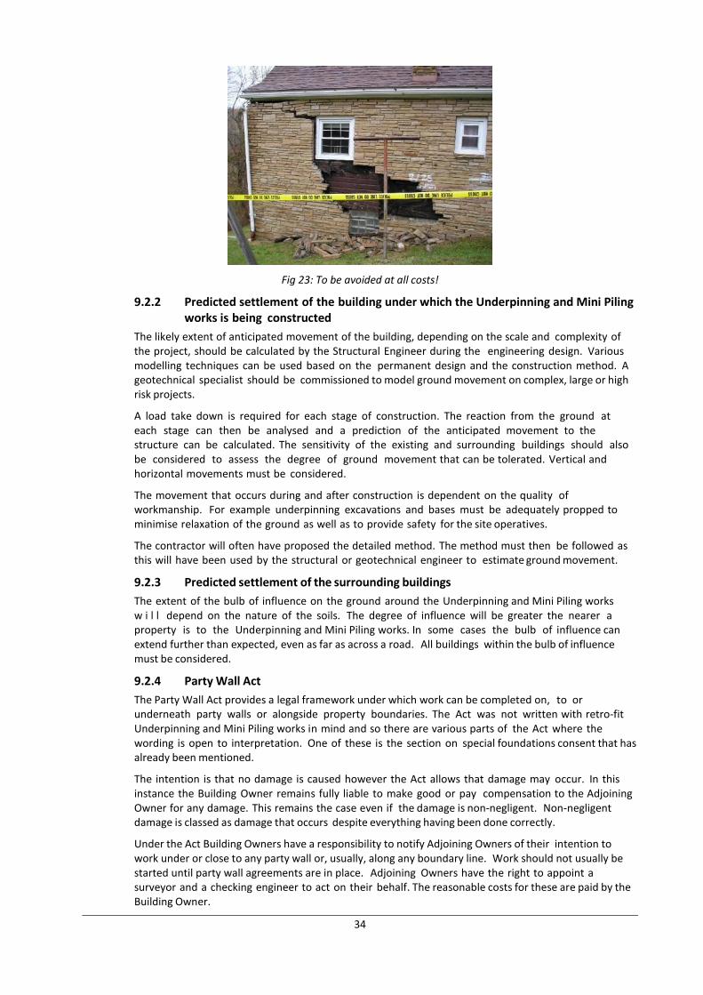
34
Fig 23: To be avoided at all costs!
9.2.2 Predicted settlement of the building under which the Underpinning and Mini Piling works is being constructed
The likely extent of anticipated movement of the building, depending on the scale and complexity of the project, should be calculated by the Structural Engineer during the engineering design. Various modelling techniques can be used based on the permanent design and the construction method. A geotechnical specialist should be commissioned to model ground movement on complex, large or high risk projects.
A load take down is required for each stage of construction. The reaction from the ground at each stage can then be analysed and a prediction of the anticipated movement to the structure can be calculated. The sensitivity of the existing and surrounding buildings should also be considered to assess the degree of ground movement that can be tolerated. Vertical and horizontal movements must be considered.
The movement that occurs during and after construction is dependent on the quality of workmanship. For example underpinning excavations and bases must be adequately propped to minimise relaxation of the ground as well as to provide safety for the site operatives.
The contractor will often have proposed the detailed method. The method must then be followed as this will have been used by the structural or geotechnical engineer to estimate ground movement.
9.2.3 Predicted settlement of the surrounding buildings
The extent of the bulb of influence on the ground around the Underpinning and Mini Piling works w i l l depend on the nature of the soils. The degree of influence will be greater the nearer a property is to the Underpinning and Mini Piling works. In some cases the bulb of influence can extend further than expected, even as far as across a road. All buildings within the bulb of influence must be considered.
9.2.4 Party Wall Act
The Party Wall Act provides a legal framework under which work can be completed on, to or underneath party walls or alongside property boundaries. The Act was not written with retro-fit Underpinning and Mini Piling works in mind and so there are various parts of the Act where the wording is open to interpretation. One of these is the section on special foundations consent that has already been mentioned.
The intention is that no damage is caused however the Act allows that damage may occur. In this instance the Building Owner remains fully liable to make good or pay compensation to the Adjoining Owner for any damage. This remains the case even if the damage is non-negligent. Non-negligent damage is classed as damage that occurs despite everything having been done correctly.
Under the Act Building Owners have a responsibility to notify Adjoining Owners of their intention to work under or close to any party wall or, usually, along any boundary line. Work should not usually be started until party wall agreements are in place. Adjoining Owners have the right to appoint a surveyor and a checking engineer to act on their behalf. The reasonable costs for these are paid by the Building Owner.
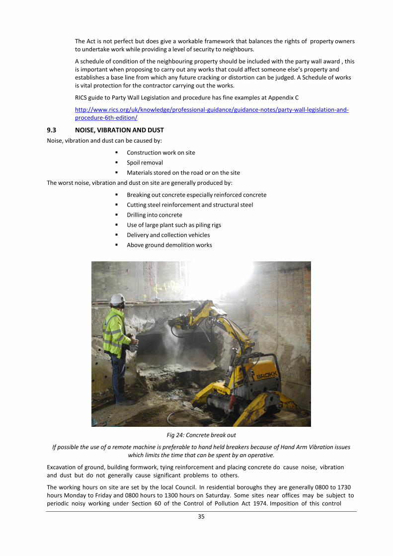
35
The Act is not perfect but does give a workable framework that balances the rights of property owners to undertake work while providing a level of security to neighbours.
A schedule of condition of the neighbouring property should be included with the party wall award , this is important when proposing to carry out any works that could affect someone else’s property and establishes a base line from which any future cracking or distortion can be judged. A Schedule of works is vital protection for the contractor carrying out the works.
RICS guide to Party Wall Legislation and procedure has fine examples at Appendix C
http://www.rics.org/uk/knowledge/professional-guidance/guidance-notes/party-wall-legislation-and-procedure-6th-edition/
9.3 NOISE, VIBRATION AND DUST
Noise, vibration and dust can be caused by:
Construction work on site
Spoil removal
Materials stored on the road or on the site
The worst noise, vibration and dust on site are generally produced by:
Breaking out concrete especially reinforced concrete
Cutting steel reinforcement and structural steel
Drilling into concrete
Use of large plant such as piling rigs
Delivery and collection vehicles
Above ground demolition works
Fig 24: Concrete break out
If possible the use of a remote machine is preferable to hand held breakers because of Hand Arm Vibration issues which limits the time that can be spent by an operative.
Excavation of ground, building formwork, tying reinforcement and placing concrete do cause noise, vibration and dust but do not generally cause significant problems to others.
The working hours on site are set by the local Council. In residential boroughs they are generally 0800 to 1730 hours Monday to Friday and 0800 hours to 1300 hours on Saturday. Some sites near offices may be subject to periodic noisy working under Section 60 of the Control of Pollution Act 1974. Imposition of this control
36
usually means that noisy working is restricted to two hours with a quiet period of two hours in between.
Actions that can be taken to reduce construction site impact include:
Keeping doors and windows closed where possible
Using muffled or silenced compressors and other plant
Using, where practical, electrically powered tools rather than air powered tools - electrical tools do not need a compressor unit
Using relatively low power handheld breaking tools for removing existing foundations
Using, where practical, non-percussive methods for removing concrete, including using diamond saws, diamond drills, concrete bursters and concrete crunchers
Using sound shielding around noisy work areas
Using non-percussive piling methods
Informing and communicating with local residents on the best times to complete very noisy works
Informing local residents of the times of very noisy works in advance
Agreeing non-noisy working times
Stopping site operatives from shouting or raising their voices unnecessarily
Banning the use of radios, other than communication radios, on site
Using good quality suppliers with modern delivery vehicles
Ensuring conveyors are well maintained and lubricated
Making sure materials are fully enclosed by waterproof and dustproof coverings especially cement and ballast
9.4 TRAFFIC CONGESTION
The main causes of traffic congestion around sites are:
Delivery and collection vehicles, notably spoil removal vehicles and ready mix concrete delivery lorries
Hoardings, skips and welfare facilities on the highway
Use of the highway for skips, materials storage and the like should generally be minimised. It is not always possible to store everything on site and in this instance the most efficient use of space should be employed.
Possible actions that could be considered are:
Implementing a Construction Traffic Management Plan (CTMP)
Limiting vehicle delivery, collection and spoil removal operations to low traffic volume times, say between 9.30am and 4pm
One way approach and departure route plan
Ensuring an adequate system of vehicle call up to avoid having multiple vehicles on site at the same time
Positioning banksmen and traffic marshals at sensible places to give local traffic the option of using alternate routes before they are committed to the road past the project
Providing the traffic marshals with communication radios
Moving the delivery or collection vehicle when local traffic wants to pass
Using the lowest impact method for spoil collection - possibly vehicles waiting under a conveyor for loading or grabs lorries rather than skips on exchange
Communicating with local residents to gain feedback on the effectiveness of the measures being taken
Avoiding deliveries and collections at times when the local refuse collection takes place
Avoiding routes past local traffic generators such as schools, especially at their expected busy traffic times
Coordinating deliveries and collection with any other nearby construction sites
37
Organising the site efficiently to minimise the need for storage on the highway
9.5 SUMMARY
Underpinning and Mini Piling works projects can cause significant negative impact on others especially if poorly planned and executed. There will always be some negative impact but this should be minimised through early engagement, imaginative planning and considerate execution.
10. FACTORS AFFECTING CHOICE OF CONSTRUCTION TECHNIQUE AND METHOD
10.1 INTRODUCTION
Health and safety considerations will override all other considerations. However health and safety excepted the remaining main factors that affect the choice of construction technique and sequence are:
Occupier's desire to live in the existing building during the works
Existing building
Party wall matters
Soil and geology
Hydrogeology
Surrounding structures
Site access
Impact on others
10.2 OCCUPIER'S DESIRE TO LIVE IN THE EXISTING BUILDING DURING THE WORKS
The property owner may wish to live in the building during the works. This will generally only be possible if the underpinning can be accessed externally. In general for insurance related works if the property has to be without a kitchen and/or bathroom facility insurers will consider paying for relocation whilst that section of the works is completed. The property in effect becomes a building site and there are many Health and Safety implications of working on an occupied property.
Where the upper floors only remain in use during the work it may be necessary to provide additional temporary works in the form of an external stairway and secured opening into the building. Internally the original stairway can then be blocked off.
There is a trade- off to be considered that balances the costs of renting alternative accommodation, replacing any floors that will be removed and any making good and decorative work against the additional cost of the structural work and construction duration if completed by tunnelling.
10.4 PARTY WALL MATTERS
The critical party wall matter, as mentioned previously, is special foundations consent, which can be given or withheld by the Adjoining Owner. Reinforced concrete underpins cannot be used without special foundations consent.
In the case where special foundations consent is not given then either mass concrete underpins with a lining RC retaining wall or a piled retaining wall solution will probably need to be used.
It is reasonably unusual now for special foundations consent not to be given, most party wall surveyors working for Adjoining Owners tend to recommend that consent is given.
10.5 SOIL AND GEOLOGY
The soil and geology in most parts of the United Kingdom where Underpinning and Mini Piling works is undertaken is generally favourable, or at least not wholly unfavourable, to below ground construction.
Generally ground can be divided into two types:
Granular, non-cohesive soils - such as sands and gravels. Granular soils tend not to be self supporting even in the short term.
Cohesive soils - such as clays. Cohesive soils tend to be self supporting at least in the short term.
General points to consider with soil and geology are:
Cohesive soils are often better for both underpinning and piling as the ground will tend to stand well as opposed to non-cohesive soils where local collapse is more likely.
38
This has practical implications for Underpinning and Mini Piling works.
Underpinning: underpin excavations in non-cohesive soils will need more thorough local shoring than in cohesive soils.
Piling: The bored holes for RC piles in non-cohesive soils will often need to be temporarily cased or use hollow stem augers in order to prevent local collapse during construction.
In addition the bulking factor of cohesive soils is generally greater than for granular deposits and therefore tends to cost slightly more to remove from site.
A site investigation consisting of an initial desk top study followed by on-site investigative work should usually be completed to ascertain the ground stratigraphy as well as to find out about groundwater, contamination of the ground and the construction of the existing foundations.
Further information on site investigation is given at appendix A to this document.
10.6 HYDROGEOLOGY
Hydrogeology deals with the distribution and movement of groundwater.
A project specific site investigation including boreholes provides the most reliable information on the extent and movement of any groundwater.
There are two critical points:
Underpinning and Mini Piling works below the ground water level poses significant additional challenges and may make some projects uneconomic. Early knowledge about any groundwater is critical.
Any permanent change to the flow of groundwater caused by the Underpinning and Mini Piling works must be considered and dealt with effectively by the permanent design.
Construction below the ground water level can generally be achieved safely using one of the following methods, covered previously in detail in section 4. Techniques used in Underpinning and Mini Piling works
Ground dewatering
Ground stabilisation through techniques such as grouting
However they all add cost, some of which will be hard to quantify fully before the works start on site.
10.7 SURROUNDING STRUCTURES
The stability of surrounding structures must be fully considered. The following points should be noted:
Where a party wall is underpinned there will be a point, usually at the front or rear elevation, where the underpinning stops and the adjacent wall remains supported on its existing foundations. The underpinned wall will be founded at depth while the adjacent wall will be founded on the existing, nearly always, shallower foundations. In this instance there is the possibility for differential movement. The degree to which this is of concern should be assessed by the Structural Engineer and relevant designs, such as transitional underpins, may be considered.
Owners of any surrounding building or structures, known as the Adjoining Owner in the Party Wall Act, should be notified of the works in advance. Adjoining Owners have the right to instruct a party wall surveyor and a structural engineer to check the permanent and temporary works designs and method of work.
10.8 SITE ACCESS
Site access can make a significant difference to how a project may be undertaken. In particular poor access will usually mean:
Piling will be possible only with smaller or mini-piling rigs which work more slowly than larger rigs, generally have less power to penetrate difficult ground and can have less exact vertical tolerances
The overall project duration will increase due to the difficulty of moving material onto site and spoil off site - extremely poor access may limit the size of some projects either because of
39
unacceptable project duration or high cost
10.9 IMPACT ON OTHERS
Some construction methods may cause greater noise, vibration, dust and traffic movement than others.
These include:
Driven piling will generally not be acceptable in urban areas because of the problems of vibration – piling methods should seek to limit vibration and disturbance giving due consideration to relevant ground conditions.
Bored piling using large rigs as they will often involve delivery and movement of large plant and reinforcement cages for insertion into the piles
Mini piling can be less disruptive
Mass concrete underpinning in excess of say 2.5m deep produces a lot of excavated material to be disposed of and hence additional concrete , which both in turn can increase traffic movements to the property.
10.10 SUMMARY
Health and safety is the most important single factor to be considered when choosing the construction technique and method.
All of the factors, together with health and safety, need to be considered for each project.
Groundwater, if present, will have major impact on the design and method of construction. The other factors will usually have less individual influence but they need to be considered individually and collectively.
11. HEALTH AND SAFETY
11.1 INTRODUCTION
Underpinning and Mini Piling works under or near existing structures has a high level of inherent construction hazard. The foundations of the project building and nearby buildings are always undermined. Deep excavations with their potential to cause local ground movement are part of everyday operations. Structural alterations involving the removal of load bearing walls and other elements are nearly always part of the works. Large amounts of material are moved around and on and off site continuously during work. And all of this takes place in generally restricted sites and in close proximity to the public going about their daily business.
In order that this work can be undertaken safely all members of the construction team, most notably the contractors, must be suitably experienced and qualified as well as being committed to safe working practices. It is critical that Clients only appoint individuals and companies who meet this high benchmark.
All Underpinning and Mini Piling works projects must have in place appropriate health and safety management with arrangements including access to competent health and safety advice on general and construction matters.
11.2 OUTLINE
This section will cover:
Safety hazards
Health hazards
Responsibilities
Health & safety of others
Designing to mitigate risk
Planning for risk management
Managing and supervising
Competence, training, and induction
Welfare arrangements
Emergency planning and procedures
Summary
40
11.3 SAFETY HAZARDS
There are numerous serious safety hazards involved in Underpinning and Mini Piling works directly below or near to existing buildings.
These hazards include:
Collapse of excavations
Collapse of existing buildings and structures
Access to work areas
Falls from height
Scaffolding and ladder safety
Existing services
Electrical handheld power tools
Mobile plant safety
Confined spaces
Fire and means of escape
Dangerous substances
Lifting operations
Lighting
General site order and slips, trips and falls on the same level
Collapse of excavations and of existing buildings and falls from height, including into excavations, are the three hazards most likely to lead to death or serious injury both to site workers and members of the public.
All temporary works associated with excavations and support to existing buildings must be undertaken in line with section 5 of this document, Temporary works.
Mitigating actions for all of these safety hazards are given at appendix C.
11.4 HEALTH HAZARDS
In addition to the safety hazards there are also significant health hazards associated with Underpinning and Mini Piling works projects. The main health hazards are:
Asbestos
Hazardous substances and processes
Respiratory disease especially from dust containing silica
Carbon monoxide and other noxious gases
Dermatitis
Damage to eyes
Noise
Hard arm vibration
Manual handling and musculoskeletal disorders
Inclement weather
Work related stress and alcohol and drug abuse are also serious health issues affecting the wider construction industry.
Mitigating actions for these health hazards are given at appendix D.
11.5 RESPONSIBILITIES
11.5.1 Outline
Individuals with health and safety responsibilities are called duty holders. The main duty holders are:
Clients – the person or organisation instructing the work who is either business or domestic
Designers - usually architects and structural engineers but designers include anyone contributing to the design of the work including those altering the
41
design or designing temporary works
Contractors – the people on site physically managing and carrying out the work
The Health and Safety at Work etc. Act 1974 (HSW Act 1974) and Construction (Design and Management) Regulations 2015 (CDM 2015) set out the main statutory duties on clients, designers, contractors and others involved in Underpinning and Mini Piling works projects. Guidance is shown in Appendix G.
Other health and safety regulations cover specific relevant hazards such as work at height, use of plant and equipment, lifting operations, hazardous substances, fire and explosion, confined spaces, and noise and vibration.
11.5.1.1 Client
Where an Underpinning and Mini Piling works project is carried out in furtherance of a business or on a domestic property the client has responsibilities under CDM 2015.
Business clients (for example a developer or landlord or commercial premise owner or occupier) have extensive duties including the requirements to check contractor competence, appoint a Principle Designer and principal contractor plus making arrangements for managing the health and safety for the project.
Domestic clients have a lesser duty please refer to Appendix G for guidance
11.5.1.2 Designers
CDM 2015 duties apply to all projects, including non-notifiable and domestic works.
Designers must seek to avoid, so far as is reasonably practicable, construction risk whilst preparing or modifying the design. This is achieved by eliminating hazards and reducing risk from remaining hazards for example using shorter beam spans or lighter beam components and in-situ assembly to reduce manual handling risks.
Designers must also provide information likely to be needed to identify and manage the remaining construction risks.
11.5.1.3 Contractors
Contractors must ensure, as far as is reasonably practicable, the control of hazards to health and safety during the works.
The contractor’s duties involve:
Planning: minimising risk and establishing precautions
Managing: implementing and maintaining precautions
Monitoring: checking and reviewing precautions
The Contractor must do all three activities throughout the project.
11.6 HEALTH AND SAFETY OF OTHERS
The health and safety of building occupiers, visitors and the general public is of paramount importance on Underpinning and Mini Piling works projects. Work must not be carried out unless the structural integrity of the building being extended and those nearby has been ensured and until work areas have been secured to prevent access by unauthorised people.
Safe areas and safe means of access and egress must be established and maintained through affected public areas with particular care being provided where elderly people or children may be involved.
Site security and access restrictions
Reasonable steps must be taken to prevent access by unauthorised persons to the project site. Only people who are explicitly authorised must be allowed access.
Authorised people must have relevant site rules explained to them, wear the required Personal Protective Equipment (PPE) and undertake any necessary site induction.
It must not be possible for members of the public, especially children, to wander onto site at any time. A common fault for Underpinning and Mini Piling works projects occurs where workers are moving materials onto site and the main site door is left open and unattended. This must not be allowed.
42
Warning signs Warning signs should be highly visible and be located where they are most likely to be seen by someone entering the site.
Works access Safe means of access and egress must be established and maintained to all areas of work.
Special attention should be taken when work is in a restricted area and all reasonable efforts should be made to ensure multiple exit points.
Access points for emergency service vehicles must be clear at all times.
On larger sites, where possible, separate pedestrian and vehicle entrances should be designated.
Vehicle access to site should avoid hazardous situations, for example being close to overhead power lines or causing obstructions to road users.
Steps must be taken to prevent dirt, mud or dust being carried out of the site onto public highways.
11.7 DESIGNING TO MITIGATE RISK
11.7.1. Outline
The design team must mitigate risk as far as reasonably practical. It is usually preferable if experienced specialist contractors and engineers are part of the design team at an early stage in order to identify the main risks.
The main areas for consideration are:
Stability of existing structures
Temporary works
Avoiding risks from other hazards
11.7.2 Stability of existing structures
The design must prevent the collapse and minimise the movement of existing or nearby structures.
Loads and their distribution must be calculated with particular attention to ensure that loads are transferred to the new Underpinning and Mini Piling works structure through elements of the building that have sufficient load bearing capacity. All load paths must be identified and checked.
Elements showing signs of distress or weakness must be strengthened to allow the safe transfer of load with a suitable factor of safety allowed to ensure that unintentional redistribution of the buildings’ load in the building fabric does not cause problems.
The strength and condition of any existing structures must be assessed to ensure that any zones of failure or separation can be predicted.
Wind loads should be calculated with full recognition given to any localised effects such as funnelling or that might result in uplift of structures such as temporary roofs.
11.7.3 Stability of the works in the temporary condition
Temporary works must be used to ensure the stability of the ground and existing buildings during the works. All temporary works must be designed, installed, monitored and removed correctly.
A Temporary Works Engineer (TWE) and a Temporary Works Coordinator (TWC) must be appointed. Both the TWE and TWC must be suitably qualified and experienced individuals.
Further detail on the correct process and responsibilities for temporary works are given in section 5 of this document.
11.7.4 Avoiding risk from other hazards
In addition to designing for structural safety all designers must seek to avoid construction risk whilst preparing or modifying the design.
In particular hazards from working at height, manual handling, confined spaces, generation of noise, vibration, and dust, and the use of hazardous and dangerous substances should be avoided in the building design as far as possible.
43
An example of designing to reduce risk from manual handling is designing structural steelwork beams with a splice or as composite beams in order to reduce the size and weight of each piece of steel
A practical action that helps design that avoids unnecessary construction risk is to involve the Underpinning and Mini Piling works contractor (who will often instruct or control the TWE and TWC) and the Structural Engineer early in the design process. Property owners frequently desire large open spaces with minimal support. These are generally possible but there are limitations and trade-offs which include health and safety considerations. Health and safety pitfalls can largely be avoided if the Underpinning and Mini Piling works contractor and Structural Engineer are involved early.
11.8 PLANNING FOR RISK MANAGEMENT
11.8.1 Outline
The project must be planned to manage risk effectively. This requires:
Gathering the required information
Assessing the significant risks
Developing methods and safe systems of work
11.8.2 Gathering the required information
All relevant information should be gathered as early as practically possible in order to allow the significant hazards to be identified and assessed. The breadth and amount of information required should be appropriate for the scale and complexity of the project.
Comprehensive information would usually be needed for a single or multiple level basement, while limited information may be needed for the deepening of an existing cellar. As a guide more information rather than less should be acquired. A competent contractor will seek to obtain as much information as possible.
A business client is required to provide designers and contractors with pre- construction information consisting of all information which is relevant to the health and safety of those engaged in or affected by the work, or who will use the structure as a future workplace. This should include local knowledge of the site and the information in any relevant existing building health and safety file.
The relevant information may include:
Site investigations.
Existing and adjoining building and structures.
Adjacent underground structures.
Location of services.
Asbestos.
Site access.
Additional detail on the relevant information that may be needed to enable planning for risk management is given in appendix E.
11.8.3 Assessing the significant risks
The Underpinning and Mini Piling works project main or principal contractor must ensure that a suitable and sufficient assessment of the risks to the health and safety of employees and others who may be affected by the works is carried out by all employers working on the project.
Risk assessments must be site and work specific. It is not adequate to use generic risk assessments, they must relate to a specific project and the activities to be undertaken on that job.
Risk assessments should be practical and provide actions that will avoid or mitigate risk. Historically risk assessments have often been overly complicated paper exercises that are then not used to implement simple actions. This approach should be avoided and straight forward risk assessment that identify the likely hazards and provide practical actions should be used instead.
In the first instance the assessment helps the main parties select the method of construction, the construction sequence, the system of work and the plant, equipment and workforce that is needed. This selection process may be reworked several times before the right mix becomes clear.
44
Once the main decisions are in place the assessment can be refined to help ensure the work will proceed smoothly with minimal risk to workers and others.
A full structural assessment must always be completed. This should identify any limitations on the proposed works and the need for any temporary or permanent works to stabilise structures prior to the main work commencing and during the works.
11.8.4 Developing methods and safe systems of work
Risk assessments should promote the preparation of site specific method statements detailing, with sketches, diagrams or photographs where possible, how the significant hazards will be managed.
Method statements should set out how the operation or activity will be carried out safely and describe the scope and sequence of works.
Specific temporary works designs will often be included as part of a method statement and will need to be available for use before structural or excavation work commences on site. However not all of the temporary works designs are needed before work starts, they can be added and amended throughout the project as required in consultation with the project temporary works engineer.
11.9 MANAGING AND MONITORING
11.9.1 General
Once the project has been designed and planned from a health and safety perspective work on site can start. The work must then be adequately managed and supervised.
Ensuring that the work is managed and monitored correctly starts with senior management and works down.
11.9.2 Director or owner reviews
Directors or company owners must take a keen interest in health and safety during all site visits and conduct a formal review of health and safety arrangements and performance during meetings with project managers and engineers.
The company director responsible for health and safety should arrange for a review of the effectiveness of the company health and safety policy, organisation and arrangements at least every twelve months or following any incident, accident or dangerous occurrence.
11.9.3 Management system
A practical health and safety management system must be in place and be used. There is no point in having a system that is not effective because it is overly complex and difficult to operate.
Typical elements of an effective health and safety management system are:
Health and safety plan presentation by the project manager to senior site management before the start of all jobs
Health and safety plan presentation by the person directly responsible for the site, for example the Contracts Manager, to the company director responsible for health and safety
Regular health and safety site visits by a company director or senior manager to each project
Health and safety site visits by an external health and safety consultant
Regular health and safety reports on each job to senior management covering risk assessments and methods for current and future phases of work
Staff inductions are completed where it is made clear that health and safety is a business critical priority and that staff are never expected to take undue health and safety risks, and must report all concerns and any near misses or incidents to site management
Site management reports and reviews of all accidents, near-misses and instances of non-compliance with lessons learned being communicated out across the company and workforce
End of job health and safety report with lessons learned being recorded and
45
disseminated
In this context regular may mean weekly or fortnightly.
11.9.4 Monitoring
Health and safety must be continuously monitored. Project managers and engineers should take a keen interest in health and safety during all site visits and conduct formal health and safety inspections at established intervals with inspection reports provided to the managing director. Project managers should monitor for health and safety compliance on all site visits, which would usually be completed on or near to a daily basis.
Site managers and Foremen are expected to monitor health and safety on a continuous basis.
11.9.5 Supervisor checks
Contractors must have procedures in place to check, throughout the working day, that the required safety precautions are being implemented. As a minimum these should ensure that:
Temporary works are in place, secure and installed in line with instructions
Excavations are correctly shored
Access to the site and for all work areas is fit for purpose
Ladders are secure and correctly installed
Edges are protected, including edges to excavations
PPE is available and being used, especially safety boots, head protection, and eye and hearing protection
Operators are not being exposed to hand arm vibration (HAV) risk from using power tools for extended periods
Work platforms are safe and secure
The correct equipment is available and in good working order
Guards on piling rigs and other plant and equipment are in place and being used correctly
Exposed reinforcement ends are protected to prevent impalement incidents
Exposure to dust is being minimised
Fuels and oils are stored correctly
Banksmen are being used to control deliveries and collections
Welfare facilities are available and serviceable Checklists are an effective tool to guide these ongoing checks.
11.9.6 Reporting health and safety risks
All staff should be briefed that reporting health and safety concerns and non- compliance up the management chain is their individual responsibility and that doing so is part of the company health and safety plan.
Reporting health and safety problems allows supervisors and managers to take corrective actions to avoid accidents and injuries.
11.10 PERSONNEL
11.10.1 Outline
Everyone involved in Underpinning and Mini Piling works, from site operatives to company directors, must be competent and adequately trained in health and safety. The Underpinning and Mini Piling works contractor needs to take the lead in this area.
11.10.2 Competency
The competence of site workers and supervisors is crucial for the safe completion of Underpinning and Mini Piling works. The lack of competent site management is a main cause of major problems on site according to the Health and Safety Executive.
To this end all managers and site foremen must have received appropriate training in site safety management and supervision.
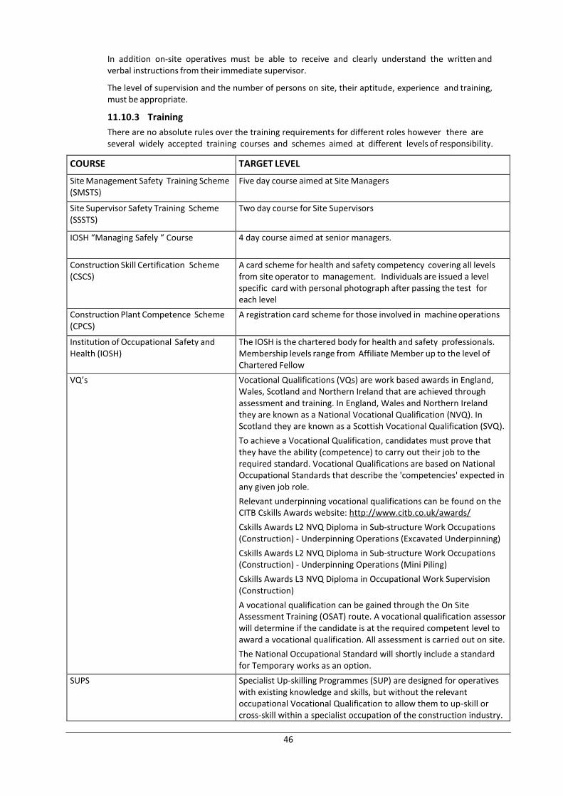
46
In addition on-site operatives must be able to receive and clearly understand the written and verbal instructions from their immediate supervisor.
The level of supervision and the number of persons on site, their aptitude, experience and training, must be appropriate.
11.10.3 Training
There are no absolute rules over the training requirements for different roles however there are several widely accepted training courses and schemes aimed at different levels of responsibility.
COURSE TARGET LEVEL
Site Management Safety Training Scheme (SMSTS)
Five day course aimed at Site Managers
Site Supervisor Safety Training Scheme (SSSTS)
Two day course for Site Supervisors
IOSH “Managing Safely “ Course 4 day course aimed at senior managers.
Construction Skill Certification Scheme (CSCS)
A card scheme for health and safety competency covering all levels from site operator to management. Individuals are issued a level specific card with personal photograph after passing the test for each level
Construction Plant Competence Scheme (CPCS)
A registration card scheme for those involved in machine operations
Institution of Occupational Safety and Health (IOSH)
The IOSH is the chartered body for health and safety professionals. Membership levels range from Affiliate Member up to the level of Chartered Fellow
VQ’s Vocational Qualifications (VQs) are work based awards in England, Wales, Scotland and Northern Ireland that are achieved through assessment and training. In England, Wales and Northern Ireland they are known as a National Vocational Qualification (NVQ). In Scotland they are known as a Scottish Vocational Qualification (SVQ).
To achieve a Vocational Qualification, candidates must prove that they have the ability (competence) to carry out their job to the required standard. Vocational Qualifications are based on National Occupational Standards that describe the 'competencies' expected in any given job role.
Relevant underpinning vocational qualifications can be found on the CITB Cskills Awards website: http://www.citb.co.uk/awards/
Cskills Awards L2 NVQ Diploma in Sub-structure Work Occupations (Construction) - Underpinning Operations (Excavated Underpinning)
Cskills Awards L2 NVQ Diploma in Sub-structure Work Occupations (Construction) - Underpinning Operations (Mini Piling)
Cskills Awards L3 NVQ Diploma in Occupational Work Supervision (Construction)
A vocational qualification can be gained through the On Site Assessment Training (OSAT) route. A vocational qualification assessor will determine if the candidate is at the required competent level to award a vocational qualification. All assessment is carried out on site.
The National Occupational Standard will shortly include a standard for Temporary works as an option.
SUPS Specialist Up-skilling Programmes (SUP) are designed for operatives with existing knowledge and skills, but without the relevant occupational Vocational Qualification to allow them to up-skill or cross-skill within a specialist occupation of the construction industry.
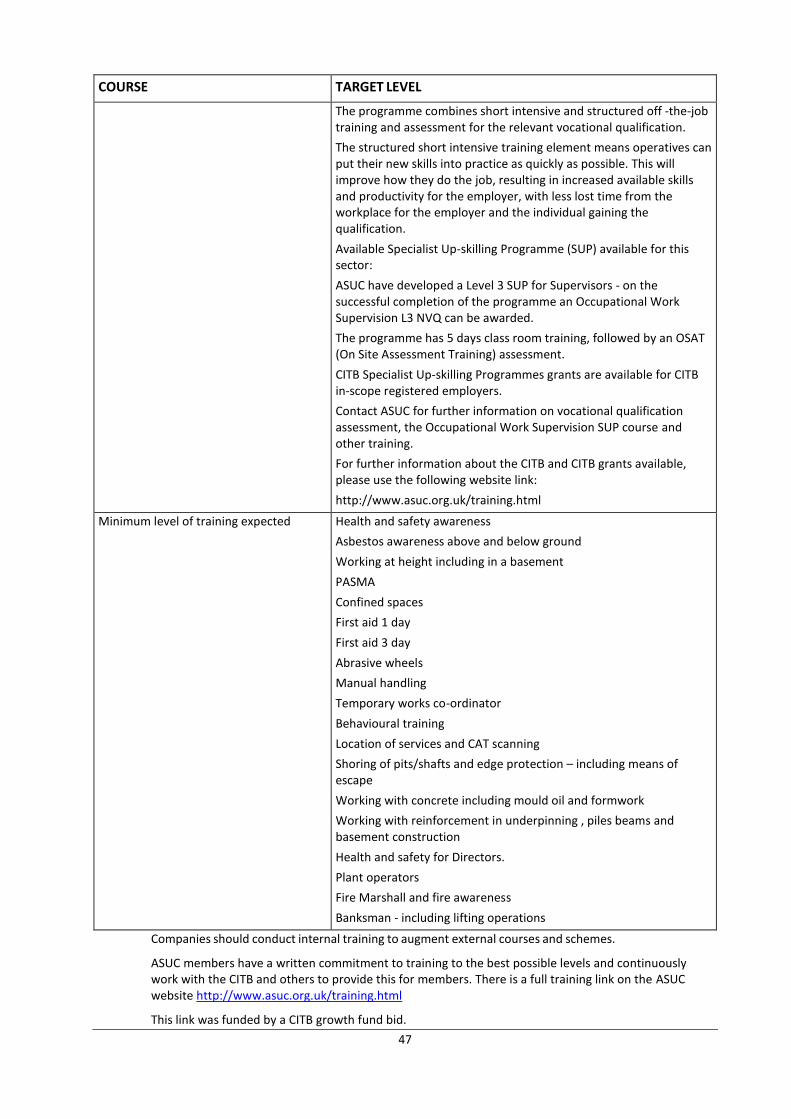
47
COURSE TARGET LEVEL
The programme combines short intensive and structured off -the-job training and assessment for the relevant vocational qualification.
The structured short intensive training element means operatives can put their new skills into practice as quickly as possible. This will improve how they do the job, resulting in increased available skills and productivity for the employer, with less lost time from the workplace for the employer and the individual gaining the qualification.
Available Specialist Up-skilling Programme (SUP) available for this sector:
ASUC have developed a Level 3 SUP for Supervisors - on the successful completion of the programme an Occupational Work Supervision L3 NVQ can be awarded.
The programme has 5 days class room training, followed by an OSAT (On Site Assessment Training) assessment.
CITB Specialist Up-skilling Programmes grants are available for CITB in-scope registered employers.
Contact ASUC for further information on vocational qualification assessment, the Occupational Work Supervision SUP course and other training.
For further information about the CITB and CITB grants available, please use the following website link:
http://www.asuc.org.uk/training.html
Minimum level of training expected Health and safety awareness
Asbestos awareness above and below ground
Working at height including in a basement
PASMA
Confined spaces
First aid 1 day
First aid 3 day
Abrasive wheels
Manual handling
Temporary works co-ordinator
Behavioural training
Location of services and CAT scanning
Shoring of pits/shafts and edge protection – including means of escape
Working with concrete including mould oil and formwork
Working with reinforcement in underpinning , piles beams and basement construction
Health and safety for Directors.
Plant operators
Fire Marshall and fire awareness
Banksman - including lifting operations
Companies should conduct internal training to augment external courses and schemes.
ASUC members have a written commitment to training to the best possible levels and continuously work with the CITB and others to provide this for members. There is a full training link on the ASUC website http://www.asuc.org.uk/training.html
This link was funded by a CITB growth fund bid.
48
11.10.4 Information and induction
Employees and others under the control of the main contractor must be provided with all information, instruction and training needed for the work to be carried out safely and without risk to health.
This should include:
A site induction
Information on risks and precautions required
Any site rules and procedures to be followed in the event of serious and imminent danger
New starters must be instructed on the specific company arrangements in place to deal with health and safety matters and their personal responsibilities.
Trainees and apprentices should develop their knowledge and skills before being asked to work in deep shafts or confined areas or to install complex excavation support. Some workers new to this type of work may find it difficult to work below ground. If they are not progressing and cannot be switched to other work there may be health and safety grounds for terminating employment.
On a site where several trades are working in close proximity a daily briefing or hazard board can help inform about planned activities or changes.
11.10.5 Site briefings and toolbox talks
Site briefings and tool box talks must be carried out to ensure those at risk are familiar with site procedures and that they are aware of all relevant points in the method statements and risk assessments as well as other construction related health and safety issues.
A health and safety section should be included as part of the daily site brief.
Toolbox talks are short periods of instruction on a specific area of site health and safety, and are often completed on a weekly basis. A record of completion of toolbox talks received by each individual should be kept.
11.10.6 Consultation
Contractors must consult employees on day-to-day health and safety conditions so that lessons can be learnt from those dealing first hand with the hazards arising from the works. Lessons learnt should be communicated to the workforce across all sites.
11.10.7 Sub-contractors and the self-employed
A competence questionnaire should be issued to and completed by all new contractors and consultants prior to their appointment. Appointments should only take place after a reply has been received and assessed by the main contractor.
Sub-contractors must be judged competent to undertake the tasks for which they are appointed and have suitable procedures to manage their risks and cooperate with others.
The health and safety performance of sub-contractors should be reviewed during their work to ensure that they maintain the required standards.
11.11 WELFARE ARRANGEMENTS
Underpinning and Mini Piling works work often takes place under harsh working conditions, frequently cold, wet and muddy.
Arrangements for the welfare of those working on site must be determined and available before work starts on site.
The arrangements may change as the project progresses but must include:
Clean and working toilets
Washbasins with hot and cold running water
Soap and a means of drying the hands, arms and face
Sinks large enough to wash face, hands and forearms
Somewhere to change, dry and store clothing
49
Drinking water and cups
A rest area to sit
Facilities for making hot drinks and for heating food
Shower facilities may need to be provided if the work is particularly dirty.
The facilities must be kept warm and well ventilated with lighting as necessary.
11.12 EMERGENCY PLANNING AND PROCEDURES
11.12.1 Serious or imminent danger
Procedures must be in place to be followed in the event of serious and imminent danger. These procedures must be communicated to all staff during site induction. The arrangements should also cover the immediate public, especially if occupied buildings are vulnerable to structural incidents or the spread of fire.
11.12.2 First aid
A first aid risk assessment must be undertaken to ensure adequate and appropriate first aid equipment, facilities and trained personnel are provided so those working on site can be given immediate help if they are injured or taken ill at work.
As a minimum each project work site must be provided with:
A stocked first-aid box including eye wash and wound dressings
A first aid trained operative
Information for those working on site about first aid arrangements
Contact details and a map showing directions to the nearest accident and emergency department
11.12.3 Accidents and near-misses
Accidents and near misses must be reported to site controllers and management. As a minimum injuries must be reported in line with Reporting of Injuries, Diseases and Dangerous Occurrences Regulations (RIDDOR) October 2013 (subject to Parliamentary approval).
11.13 SUMMARY
Underpinning and Mini Piling works projects have significant health and safety considerations which if not effectively planned and managed will cause high health and safety risk to construction site operatives and members of the public. They are among the highest risk construction activity that most clients will undertake and will generally involve major structural work undermining existing structures. The health and safety effort needed to undertake these projects safely is significant and requires training, experience and commitment.
In order that Underpinning and Mini Piling works projects are completed safely it is critical that clients understand that this is the case and that they only appoint responsible, competent and experienced designers and contractors.
12. THE PROJECT TEAM
12.1 INTRODUCTION
The foundation of a safe and efficient project is an excellent team with the right knowledge, competency and experience.
There is no set composition for an Underpinning and Mini Piling works project team and not all of those covered in this section will be included in every project probably with the exception of the design or structural engineer who will always be needed. The best results will be achieved by a positive, cooperative approach with each team member being responsible for their own fields and looking to support other team members.
The project team may include some or all of the following:
Client
Structural or Design Engineer - always needed
Temporary Works Engineer (TWE)
50
Temporary Works Coordinator (TWC)
Principal Contractor
Party Wall Surveyor
Quantity Surveyor
Principle Designer
Others
12.2 CLIENT
The client is the person for whom the work is being undertaken. They can be either a business client or a domestic client. It should be remembered that both business and domestic clients have specific health and safety responsibilities under CDM 2015.
Underpinning and Mini Piling works projects are most efficient when the design remains the same throughout the project especially once construction has started. This requires the client and the whole team to think through the project in reasonable detail at the beginning. Failure to do this will often be the root cause of costly and frustrating changes and compromises later in the project. In general the later that changes happen during a project the greater the increase in cost and delay.
Clients may assign their own Project Manager or someone to act as their representative, usually called the Client's Representative. This can be effective but requires that the Project Manager or Client's Representative either has decision making authority or can get decisions from the client quickly.
Responsible, practical and imaginative clients can make a significant positive contribution to the safe and effective construction of their Underpinning and Mini Piling works projects.
12.3 STRUCTURAL OR DESIGN ENGINEER
The Engineer is responsible for the permanent structural design of the works. The structural design must:
Create a structurally sound new building
Provide adequate support to minimise damage to existing buildings
Avoid or minimise risk during construction
It is important that the Engineer or someone who has a good knowledge of the likely structural limitations is involved early in the project as practical engineering trade-offs are frequent especially in more demanding Underpinning and Mini Piling works designs.
The structural design of any piles will often be completed by an engineer working directly for the piling contractor. The structural engineer and the pile design engineer will need to coordinate on matters including pile loadings, lateral strength and allowable horizontal movement.
Some engineers will not be experienced in Underpinning and Mini Piling works under or near to existing buildings. In this instance it may be useful to seek input from an experienced specialist contractor.
12.4 TEMPORARY WORKS ENGINEER (TWE)
The Temporary Works Engineer (TWE) is responsible for designing the temporary works that will maintain structural stability from the start of the project until the permanent works are completed.
In some instances the Structural Engineer may also be the TWE but the TWE will often be an independent consulting engineer or may work for the Underpinning and Mini Piling works contractor.
A TWE should be appointed in all but the most straight forward cellar extension.
Further details on the responsibilities of the TWE are given in section 5 Temporary works.
12.5 TEMPORARY WORKS COORDINATOR (TWC)
The Temporary Works Coordinator (TWC) is responsible for overseeing all aspects of the temporary works on site except for their design. The TWC will often work for the Underpinning and Mini Piling works contractor.
Further details on the responsibilities of the TWC are also given in section 5 Temporary works.
12.6 PRINCIPAL CONTRACTOR
The Principal Contractor is responsible for managing the works on site in a safe and productive manner. The Principal Contractor during the structural and waterproofing Underpinning and Mini Piling works could be the
51
Underpinning and Mini Piling works contractor.
The Principal Contractor's main responsibilities usually include:
Health and safety
Risk assessments
Construction sequence and method statements
Safe systems of work
Plan for reduction of impact on others
Programme
Site layout
Traffic management
Site set-up
Detailed work plans
Supervision of labour and subcontractors on site
Installation and monitoring of temporary works
Materials ordering and storage
Excavation and spoil removal
Construction
Quality assurance
The contractor's overarching priority should be health and safety and this should be core to all activities.
The number of contractors involved in a project will vary from one contracting firm being responsible for all aspects of the work through to multiple contractors working either for one main contractor or directly for the client. In general a good result will be achieved from having one contractor responsible for the Underpinning and Mini Piling works and waterproofing work, though this contractor may use subcontractors.
12.7 PARTY WALL SURVEYOR
A Party Wall Surveyor (PWS) is usually appointed to deal with putting in place party wall awards with the owners of nearby structures as required by the Party Wall etc. Act 1996 (the Act). Anyone can do this and no qualification or training is legally required however party wall matters for basements are complex and have certain nuances that make it advisable to appoint a building surveyor who has experience with party wall awards for Underpinning and Mini Piling works.
It should be remembered that the Adjoining Owner has the right to appoint their own PWS and an independent structural engineer to check the permanent design and the proposed construction method as it affects their building.
12.8 QUANTITY SURVEYOR
Clients will sometimes appoint a Quantity Surveyor (QS). Quantity Surveyor's main responsibilities are related to costs and contracts.
12.9 PRINCIPLE DESIGNER
Construction Design and Management Regulations 2015 require that all construction projects undertaken for a commercial or domestic client must have a Principle Designer.
Guidance is included in Appendix G.
A good Principle Designer will make a positive contribution to the safety and the efficiency of the project.
12.10 SUMMARY
A good team is fundamental to a safe and efficient project. Choosing the right team will be one of the client's most critical tasks. Involving an experienced and competent contractor as part of this team early in the process will always be beneficial.
52
13. PROCUREMENT
13.1 INTRODUCTION
There are four main recognised procurement methods for construction work.
Traditional
Design and build
Management
Integrated
There is no single best method and they each have advantages and disadvantages.
13.2 TRADITIONAL
13.2.1 Outline
In the traditional method the design process is separate from the construction work. Full design drawings and documentation is usually prepared by the design team for the client. The design information will be issued and contractors will provide a competitive price on this basis. A contractor will then be selected to complete the work.
There are three broad types of traditional contract.
Lump sum
Measurement
Cost reimbursement
13.2.2 Lump sum
With lump sum contracts the contract sum is determined before the construction work starts. Lump sum contracts are usually priced using the design drawings and supporting documents such as specifications and work schedules. Firm bills of quantities may sometimes be used. Variations in price will occur only if:
The client instructs a design change, or
An unexpected condition is encountered, such as a previously unknown obstruction underground. The possible unexpected conditions should usually be raised at some point prior to the start of the works.
Lump sum contracts based on drawings and additional information are common in Underpinning and Mini Piling works projects.
13.2.3 Measurement
The contract sum for measurement contracts is not finalised until completion of the project, where it is assessed on remeasurement to a previously agreed basis. Bills of quantities are a list of work items with a price per unit for each work item. Bills of quantities are often used in measurement contracts.
This type of contract is usually used where the works to be carried out by the contractor cannot be measured accurately before tender.
One form of measurement contract will have an initial set of drawings and a bill of quantities. The drawings are used as a guide to the expected quantities but a measure will be completed at the end of the works and the contract sum confirmed.
Underpinning and Mini Piling works projects are generally accurately designed before work commences so measurement contracts are not usually the most appropriate contract type.
Sometimes clients or their quantity surveyors look to use a bill of quantities to price variations caused by design changes. This can work but may not always be appropriate because the cost of completing a set amount of a certain type of work can vary markedly at different places and times on one project. For example completing one linear metre of underpinning at five metres below ground level and below the water table will take more effort and be more costly than completing one linear metre of underpinning above the water table and at ground level.
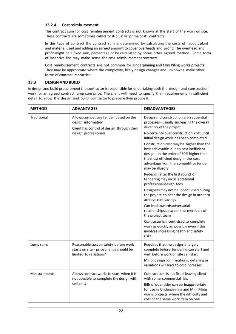
53
13.2.4 Cost reimbursement
The contract sum for cost reimbursement contracts is not known at the start of the work on site. These contracts are sometimes called 'cost-plus' or 'prime cost' contracts.
In this type of contract the contract sum is determined by calculating the costs of labour, plant and material used and adding an agreed amount to cover overheads and profit. The overhead and profit might be a fixed sum, percentage or be calculated by some other agreed method. Some form of incentive fee may make sense for cost reimbursement contracts.
Cost reimbursement contracts are not common for Underpinning and Mini Piling works projects. They may be appropriate where the complexity, likely design changes and unknowns make other forms of contract impractical.
13.3 DESIGN AND BUILD
In design and build procurement the contractor is responsible for undertaking both the design and construction work for an agreed contract lump sum price. The client will need to specify their requirements in sufficient detail to allow the design and build contractor to prepare their proposal.
METHOD ADVANTAGES DISADVANTAGES
Traditional Allows competitive tender based on the design information
Client has control of design through their design professionals
Design and construction are sequential processes - usually increasing the overall duration of the project
No certainty over construction cost until initial design work has been completed
Construction cost may be higher than the best achievable due to cost inefficient design - in the order of 30% higher than the most efficient design - the cost advantage from the competitive tender may be illusory
Redesign after the first round of tendering may incur additional professional design fees
Designers may not be incentivised during the project to alter the design in order to achieve cost savings
Can lead towards adversarial relationships between the members of the project team
Contractor is incentivised to complete work as quickly as possible even if this involves increasing health and safety risks
Lump sum: Reasonable cost certainty before work starts on site - price change should be limited to variations*
Requires that the design is largely complete before tendering can start and well before work on site can start
Minor design confirmations, detailing or variations will lead to cost increases
Measurement: Allows contract works to start when it is not possible to complete the design with certainty
Contract sum is not fixed leaving client with some commercial risk.
Bills of quantities can be inappropriate for use in Underpinning and Mini Piling works projects where the difficulty and cost of the same work item on one
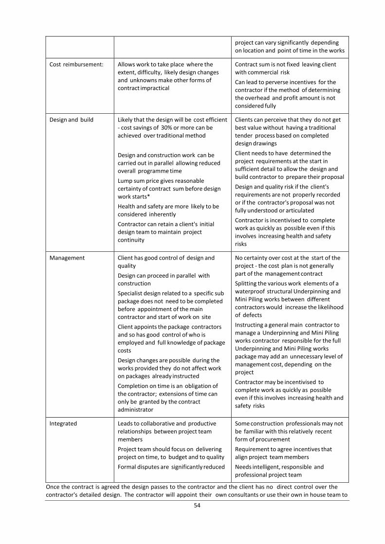
54
Once the contract is agreed the design passes to the contractor and the client has no direct control over the contractor's detailed design. The contractor will appoint their own consultants or use their own in house team to
project can vary significantly depending on location and point of time in the works
Cost reimbursement: Allows work to take place where the extent, difficulty, likely design changes and unknowns make other forms of contract impractical
Contract sum is not fixed leaving client with commercial risk
Can lead to perverse incentives for the contractor if the method of determining the overhead and profit amount is not considered fully
Design and build Likely that the design will be cost efficient - cost savings of 30% or more can be achieved over traditional method
Design and construction work can be carried out in parallel allowing reduced overall programme time
Lump sum price gives reasonable certainty of contract sum before design work starts*
Health and safety are more likely to be considered inherently
Contractor can retain a client's initial design team to maintain project continuity
Clients can perceive that they do not get best value without having a traditional tender process based on completed design drawings
Client needs to have determined the project requirements at the start in sufficient detail to allow the design and build contractor to prepare their proposal
Design and quality risk if the client's requirements are not properly recorded or if the contractor's proposal was not fully understood or articulated
Contractor is incentivised to complete work as quickly as possible even if this involves increasing health and safety risks
Management Client has good control of design and quality
Design can proceed in parallel with construction
Specialist design related to a specific sub package does not need to be completed before appointment of the main contractor and start of work on site
Client appoints the package contractors and so has good control of who is employed and full knowledge of package costs
Design changes are possible during the works provided they do not affect work on packages already instructed
Completion on time is an obligation of the contractor; extensions of time can only be granted by the contract administrator
No certainty over cost at the start of the project - the cost plan is not generally part of the management contract
Splitting the various work elements of a waterproof structural Underpinning and Mini Piling works between different contractors would increase the likelihood of defects
Instructing a general main contractor to manage a Underpinning and Mini Piling works contractor responsible for the full Underpinning and Mini Piling works package may add an unnecessary level of management cost, depending on the project
Contractor may be incentivised to complete work as quickly as possible even if this involves increasing health and safety risks
Integrated Leads to collaborative and productive relationships between project team members
Project team should focus on delivering project on time, to budget and to quality
Formal disputes are significantly reduced
Some construction professionals may not be familiar with this relatively recent form of procurement
Requirement to agree incentives that align project team members
Needs intelligent, responsible and professional project team
55
complete the design.
The client can continue to instruct overall design changes for example an increase in size or Underpinning and Mini Piling works depth. The contractor should provide a price for the change and obtain an instruction from the client before proceeding with the design change.
The contractor is obliged to complete the project for the agreed contract sum. Variations to the price should apply in the same way as for a traditional lump sum contract.
13.4 MANAGEMENT
In the management procurement method a main or principal contractor is appointed to manage the project while the work is completed using a series of separate works or trade contracts. The main contractor is responsible for managing the project through the various works packages.
The client will usually start by appointing design consultants and a contract administrator to prepare drawings, a project specification and a cost plan. The client will have direct control of the design throughout the project through their professional team.
The contractor is appointed by negotiation or tender and interview. The works packages are usually let by competitive tender.
The main contractor is paid for managing the project through the various works packages.
13.5 INTEGRATED
Integrated procurement, sometimes known as collaborative procurement or partnering, emerged in the 1990s in response to the often adversarial situations encountered in major construction projects which used the three existing procurement methods.
The intention of the integrated procurement method is to focus all the project participants on the mutual objectives of delivering a project on time, to budget and to quality. It is about working as a team, regardless of organisation or location, to meet a client's needs. A central tenet is that risk and reward are shared by all parties in a way that aligns their actions with a successful project outcome.
The UK government's 1994 Latham Report 'Constructing the Team' started the thinking behind integrated procurement. One of the main recommendations of the report was compulsory inclusion of latent defects insurance on all construction projects in order to overcome the tension that exists in construction work caused by it not being possible to know at the time of completion if there are any problems with the works that are not apparent at that time.
Latent defects insurance is covered in more detail in the Insurance section however it is worth noting at this point that the ASUC Underpinning and Mini Piling works Insurance Guarantee (BIG) Scheme is a latent defects insurance in line with the Latham Report and supports collaborative, integrated procurement.
Integrated procurement has been recognised as fundamental in the success of major construction projects like the London 2012 Olympics. There are several forms of contract which support integrated procurement for major works. The most well known is the New Engineering Contract (NEC), or NEC Engineering and Construction Contract.
13.6 COMPARISON OF PROCUREMENT METHODS
Note: * In construction contracts a fixed or lump sum price will still change based on variations. Variations can be either as a result of client instructed design changes or due to other conditions occurring such as meeting unexpected obstacles in the ground or unexpected ground water.
13.7 SUMMARY
Underpinning and Mini Piling works projects are complex and have an unavoidable element of uncertainty before and during the work on site. In addition they place the client's and the property of others at risk. These factors make it particularly important to choose the most appropriate form of procurement that incentivises safe and efficient construction.
14. INSURANCE
14.1 INTRODUCTION
Underpinning and Mini Piling works projects are major works involving various hazards which can lead to
56
problems ranging from injury to a member of the public through to a structural failure. It is important that the right insurances are in place to protect all parties.
This section outlines the various types of insurance that either should or could be put in place.
Professional Indemnity insurance (PI)
Employer’s Liability insurance (EL)
Public Liability insurance (PL)
Contractors All Risks (CAR)
Non-negligent insurance (JCT 21.2.1 / 6.2.4 / 6.5.1 insurance)
Existing building insurance
Insurance for client's property for non-negligent damage
All insurance cover depends on the wording of the specific policy. Proper checks should be completed before appointing contractors or designers, and before the start of work.
14.2 PROFESSIONAL INDEMNITY INSURANCE
Professional indemnity insurance (PI) provides cover for professional error, omissions or negligence. All designers, notably architects and engineers, should have professional indemnity insurance in place at a level appropriate for the value and scope of the works. In particular the person designing the temporary works, who may well not be the main structural engineer, should have PI insurance.
Design and build contractors and any party involved in updating, changing or amending any design element, no matter how small, should have adequate PI cover.
14.3 EMPLOYER’S LIABILITY INSURANCE
Employer’s Liability (EL) insurance provides cover for the employer in the event that an employee or former employee makes a claim against the company. Employers have a legal responsibility for the health and safety of their staff while they are at work. Employees may be injured at work or they may become ill while at work or at some time later as a result of work activities.
Employer’s Liability insurance is a legal requirement for companies that employ any staff. The minimum legal level of EL insurance is £5 million. This is a minimum and in practice £10 million cover for Underpinning and Mini Piling works contractors would be a sensible level.
14.4 PUBLIC LIABILITY INSURANCE
Public Liability insurance (PL) provides cover for a company against claims from third parties. The building owner and family, neighbours and other members of the public would usually count as third parties. Any claims would usually be due to physical injury to the third party or to damage to property owned by the third party.
PL claims require that the claimant demonstrate that the Contractor has acted negligently. For example a PL claim against a contractor by the building owner would require the building owner to demonstrate that the contractor had acted negligently and that this negligence had led to loss, say, damage to the existing building.
It is very important that the contractor’s PL insurance provides cover for:
The activity which the contractor is undertaking – so excavating and construction down to the depth below ground of the proposed project. It can be quite common that contractors undertaking deep excavations do not have cover for the depth at which they are working. This should be checked.
Damage to the existing building above the works. The existing building above the works, often called Existing Buildings/Structure or the Superstructure or similar, is often specifically excluded from the cover provided by a PL policy. In this instance the contractor would not be covered for negligent damage caused to the existing building and so, in the event of a major structural failure to the existing building, the building owner would probably not be able to recover the full amount of the loss from the contractor. Again the existence of superstructure cover should be confirmed before appointing a contractor.
Public liability insurance is not a legal requirement however it would be extremely foolhardy to have works undertaken by a contractor without adequate PL insurance.
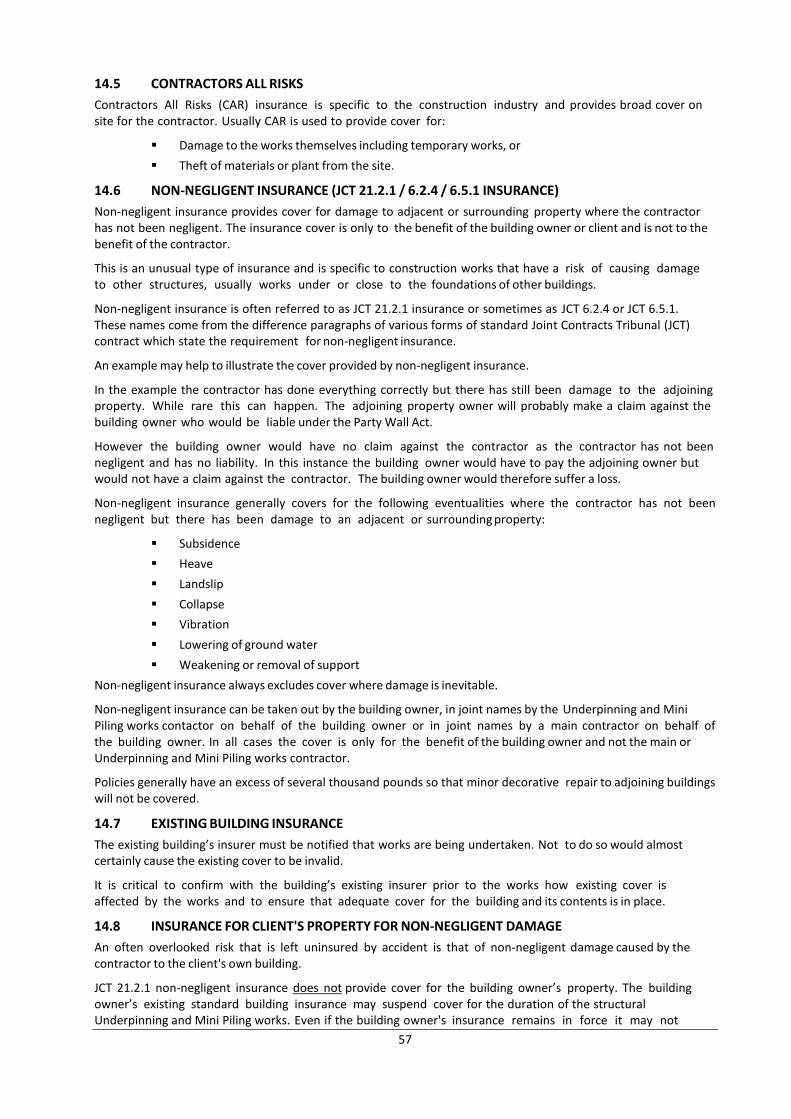
57
14.5 CONTRACTORS ALL RISKS
Contractors All Risks (CAR) insurance is specific to the construction industry and provides broad cover on site for the contractor. Usually CAR is used to provide cover for:
Damage to the works themselves including temporary works, or
Theft of materials or plant from the site.
14.6 NON-NEGLIGENT INSURANCE (JCT 21.2.1 / 6.2.4 / 6.5.1 INSURANCE)
Non-negligent insurance provides cover for damage to adjacent or surrounding property where the contractor has not been negligent. The insurance cover is only to the benefit of the building owner or client and is not to the benefit of the contractor.
This is an unusual type of insurance and is specific to construction works that have a risk of causing damage to other structures, usually works under or close to the foundations of other buildings.
Non-negligent insurance is often referred to as JCT 21.2.1 insurance or sometimes as JCT 6.2.4 or JCT 6.5.1. These names come from the difference paragraphs of various forms of standard Joint Contracts Tribunal (JCT) contract which state the requirement for non-negligent insurance.
An example may help to illustrate the cover provided by non-negligent insurance.
In the example the contractor has done everything correctly but there has still been damage to the adjoining property. While rare this can happen. The adjoining property owner will probably make a claim against the building owner who would be liable under the Party Wall Act.
However the building owner would have no claim against the contractor as the contractor has not been negligent and has no liability. In this instance the building owner would have to pay the adjoining owner but would not have a claim against the contractor. The building owner would therefore suffer a loss.
Non-negligent insurance generally covers for the following eventualities where the contractor has not been negligent but there has been damage to an adjacent or surrounding property:
Subsidence
Heave
Landslip
Collapse
Vibration
Lowering of ground water
Weakening or removal of support
Non-negligent insurance always excludes cover where damage is inevitable.
Non-negligent insurance can be taken out by the building owner, in joint names by the Underpinning and Mini Piling works contactor on behalf of the building owner or in joint names by a main contractor on behalf of the building owner. In all cases the cover is only for the benefit of the building owner and not the main or Underpinning and Mini Piling works contractor.
Policies generally have an excess of several thousand pounds so that minor decorative repair to adjoining buildings will not be covered.
14.7 EXISTING BUILDING INSURANCE
The existing building’s insurer must be notified that works are being undertaken. Not to do so would almost certainly cause the existing cover to be invalid.
It is critical to confirm with the building’s existing insurer prior to the works how existing cover is affected by the works and to ensure that adequate cover for the building and its contents is in place.
14.8 INSURANCE FOR CLIENT'S PROPERTY FOR NON-NEGLIGENT DAMAGE
An often overlooked risk that is left uninsured by accident is that of non-negligent damage caused by the contractor to the client's own building.
JCT 21.2.1 non-negligent insurance does not provide cover for the building owner’s property. The building owner’s existing standard building insurance may suspend cover for the duration of the structural Underpinning and Mini Piling works. Even if the building owner's insurance remains in force it may not
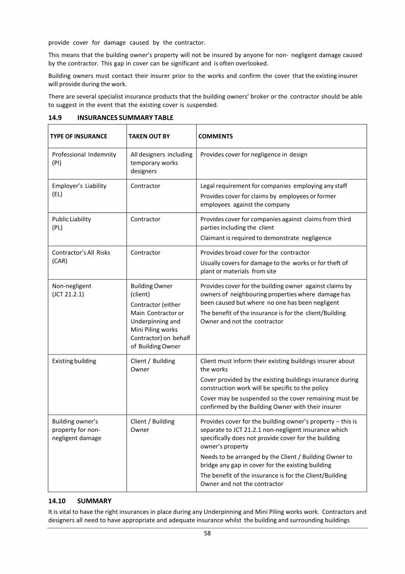
58
provide cover for damage caused by the contractor.
This means that the building owner’s property will not be insured by anyone for non- negligent damage caused by the contractor. This gap in cover can be significant and is often overlooked.
Building owners must contact their insurer prior to the works and confirm the cover that the existing insurer will provide during the work.
There are several specialist insurance products that the building owners’ broker or the contractor should be able to suggest in the event that the existing cover is suspended.
14.9 INSURANCES SUMMARY TABLE
TYPE OF INSURANCE TAKEN OUT BY COMMENTS
Professional Indemnity (PI)
All designers including temporary works designers
Provides cover for negligence in design
Employer’s Liability (EL)
Contractor Legal requirement for companies employing any staff
Provides cover for claims by employees or former employees against the company
Public Liability (PL)
Contractor Provides cover for companies against claims from third parties including the client
Claimant is required to demonstrate negligence
Contractor’s All Risks (CAR)
Contractor Provides broad cover for the contractor
Usually covers for damage to the works or for theft of plant or materials from site
Non-negligent (JCT 21.2.1)
Building Owner (client)
Contractor (either Main Contractor or Underpinning and Mini Piling works Contractor) on behalf of Building Owner
Provides cover for the building owner against claims by owners of neighbouring properties where damage has been caused but where no one has been negligent
The benefit of the insurance is for the client/Building Owner and not the contractor
Existing building Client / Building Owner
Client must inform their existing buildings insurer about the works
Cover provided by the existing buildings insurance during construction work will be specific to the policy
Cover may be suspended so the cover remaining must be confirmed by the Building Owner with their insurer
Building owner’s property for non- negligent damage
Client / Building Owner
Provides cover for the building owner’s property – this is separate to JCT 21.2.1 non-negligent insurance which specifically does not provide cover for the building owner’s property
Needs to be arranged by the Client / Building Owner to bridge any gap in cover for the existing building
The benefit of the insurance is for the Client/Building Owner and not the contractor
14.10 SUMMARY
It is vital to have the right insurances in place during any Underpinning and Mini Piling works work. Contractors and designers all need to have appropriate and adequate insurance whilst the building and surrounding buildings
59
should also all be properly covered.
Insurance cover for Underpinning and Mini Piling works projects is complex and advice from experienced parties should be sought. The contractor, the contractor's insurance broker and the building owner’s insurance broker are probably the right start points for checking that appropriate cover is in place.
15. GUARANTEES
15.1 INTRODUCTION
Guarantees for building work, like many guarantees, often promise much but deliver little. There are multiple types of guarantees available and to some extent each guarantee is different from the next. The detailed wording for each guarantee must be understood in order to know what true level of protection is provided.
This section will give an outline of the various types of guarantees that are often provided.
Company guarantees
Product guarantees
Insurance backed guarantees
Latent defects insurance
15.2 COMPANY GUARANTEES
Contractors will usually provide some sort of company guarantee or warranty. The wording of the guarantee should be read carefully and any areas of doubt clarified. There will often be exclusions that will limit significantly the cover provided. The wording will often be ambiguous or unclear in favour of the contractor.
Guarantees should provide security over and above that provided by law. Companies cannot avoid their legal liabilities.
It is worth remembering that a company guarantee is only as sound as the company that stands behind it. If a company no longer exists then the guarantee is worthless.
15.3 PRODUCT GUARANTEES
Several specific product guarantees will often be provided from the product manufacturer notably for waterproofing membranes and pumps for ground water and foul water removal. In each case the guarantee wording needs to be read carefully to confirm the cover provided.
Consequential damages – damage to property resulting from a failure in the product – will usually be excluded. This is an important limitation on a guarantee. Also the workmanship involved in the installation of the product will not be covered by a suppliers’ product guarantee.
15.4 INSURANCE BACKED GUARANTEES
Insurance backed guarantees (IBGs) are usually provided by contractors to clients. They are insurance products which should provide cover to the client in the event that the contractor ceases to trade during the period of either the contractor's:
Company guarantee, or
Legal liability
There are two significant points that need to be considered regarding insurance backed guarantees:
The insurance backed guarantee will only provide cover to the same extent as if the contractor were still trading. If the building owner would have had to demonstrate negligence by the contractor originally then the same requirement for the building owner to demonstrate negligence will be required by the insurer. The IBG is not a broad, comprehensive cover for any defects with the work.
The underwriters providing insurance backed guarantees can be based in offshore jurisdictions. Proceeding with a claim against an unwilling underwriter who is not directly subject to UK law may be difficult. Some underwriters may also have limited balance sheets and will not have funds available to pay claims. It is worth confirming the name and financial strength of any insurer underwriting a guarantee.
It is important to read and understand fully the terms and cover for any insolvency guarantees as they can appear to provide broad cover which sometimes may not be the case.
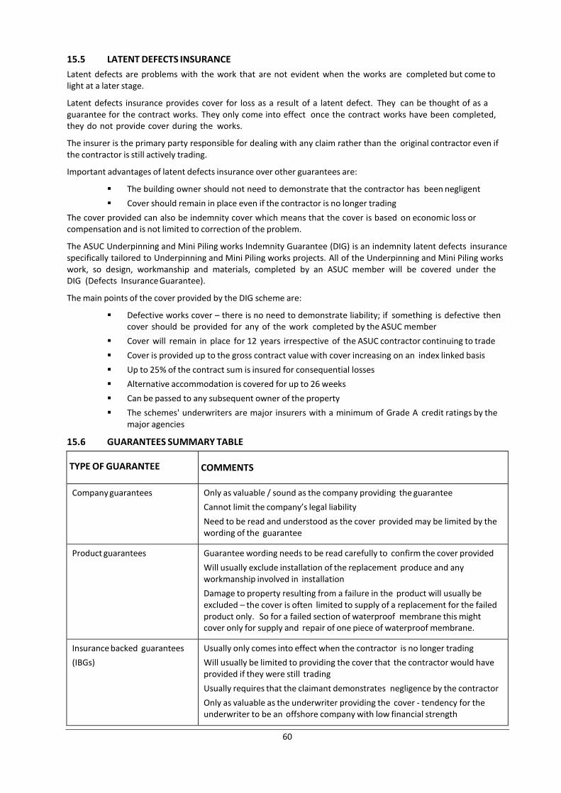
60
15.5 LATENT DEFECTS INSURANCE
Latent defects are problems with the work that are not evident when the works are completed but come to light at a later stage.
Latent defects insurance provides cover for loss as a result of a latent defect. They can be thought of as a guarantee for the contract works. They only come into effect once the contract works have been completed, they do not provide cover during the works.
The insurer is the primary party responsible for dealing with any claim rather than the original contractor even if the contractor is still actively trading.
Important advantages of latent defects insurance over other guarantees are:
The building owner should not need to demonstrate that the contractor has been negligent
Cover should remain in place even if the contractor is no longer trading
The cover provided can also be indemnity cover which means that the cover is based on economic loss or compensation and is not limited to correction of the problem.
The ASUC Underpinning and Mini Piling works Indemnity Guarantee (DIG) is an indemnity latent defects insurance specifically tailored to Underpinning and Mini Piling works projects. All of the Underpinning and Mini Piling works work, so design, workmanship and materials, completed by an ASUC member will be covered under the DIG (Defects Insurance Guarantee).
The main points of the cover provided by the DIG scheme are:
Defective works cover – there is no need to demonstrate liability; if something is defective then cover should be provided for any of the work completed by the ASUC member
Cover will remain in place for 12 years irrespective of the ASUC contractor continuing to trade
Cover is provided up to the gross contract value with cover increasing on an index linked basis
Up to 25% of the contract sum is insured for consequential losses
Alternative accommodation is covered for up to 26 weeks
Can be passed to any subsequent owner of the property
The schemes' underwriters are major insurers with a minimum of Grade A credit ratings by the major agencies
15.6 GUARANTEES SUMMARY TABLE
TYPE OF GUARANTEE COMMENTS
Company guarantees Only as valuable / sound as the company providing the guarantee
Cannot limit the company’s legal liability
Need to be read and understood as the cover provided may be limited by the wording of the guarantee
Product guarantees Guarantee wording needs to be read carefully to confirm the cover provided
Will usually exclude installation of the replacement produce and any workmanship involved in installation
Damage to property resulting from a failure in the product will usually be excluded – the cover is often limited to supply of a replacement for the failed product only. So for a failed section of waterproof membrane this might cover only for supply and repair of one piece of waterproof membrane.
Insurance backed guarantees
(IBGs)
Usually only comes into effect when the contractor is no longer trading
Will usually be limited to providing the cover that the contractor would have provided if they were still trading
Usually requires that the claimant demonstrates negligence by the contractor
Only as valuable as the underwriter providing the cover - tendency for the underwriter to be an offshore company with low financial strength
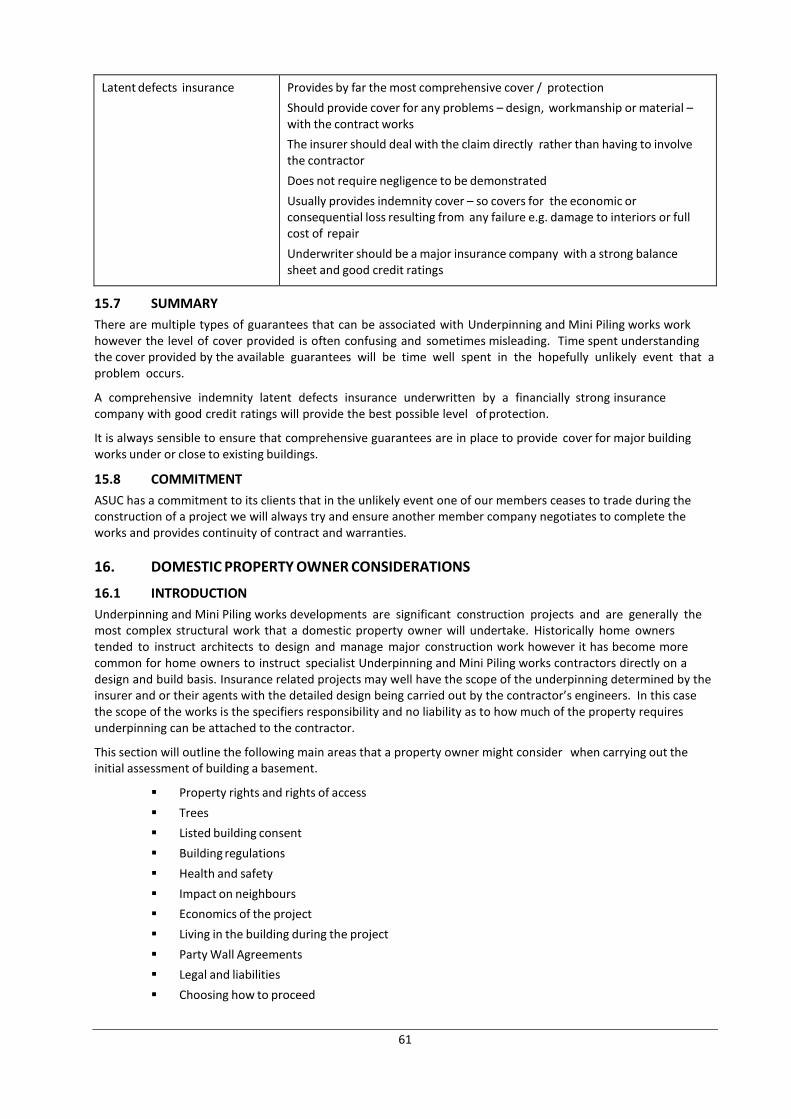
61
Latent defects insurance Provides by far the most comprehensive cover / protection
Should provide cover for any problems – design, workmanship or material – with the contract works
The insurer should deal with the claim directly rather than having to involve the contractor
Does not require negligence to be demonstrated
Usually provides indemnity cover – so covers for the economic or consequential loss resulting from any failure e.g. damage to interiors or full cost of repair
Underwriter should be a major insurance company with a strong balance sheet and good credit ratings
15.7 SUMMARY
There are multiple types of guarantees that can be associated with Underpinning and Mini Piling works work however the level of cover provided is often confusing and sometimes misleading. Time spent understanding the cover provided by the available guarantees will be time well spent in the hopefully unlikely event that a problem occurs.
A comprehensive indemnity latent defects insurance underwritten by a financially strong insurance company with good credit ratings will provide the best possible level of protection.
It is always sensible to ensure that comprehensive guarantees are in place to provide cover for major building works under or close to existing buildings.
15.8 COMMITMENT
ASUC has a commitment to its clients that in the unlikely event one of our members ceases to trade during the construction of a project we will always try and ensure another member company negotiates to complete the works and provides continuity of contract and warranties.
16. DOMESTIC PROPERTY OWNER CONSIDERATIONS
16.1 INTRODUCTION
Underpinning and Mini Piling works developments are significant construction projects and are generally the most complex structural work that a domestic property owner will undertake. Historically home owners tended to instruct architects to design and manage major construction work however it has become more common for home owners to instruct specialist Underpinning and Mini Piling works contractors directly on a design and build basis. Insurance related projects may well have the scope of the underpinning determined by the insurer and or their agents with the detailed design being carried out by the contractor’s engineers. In this case the scope of the works is the specifiers responsibility and no liability as to how much of the property requires underpinning can be attached to the contractor.
This section will outline the following main areas that a property owner might consider when carrying out the initial assessment of building a basement.
Property rights and rights of access
Trees
Listed building consent
Building regulations
Health and safety
Impact on neighbours
Economics of the project
Living in the building during the project
Party Wall Agreements
Legal and liabilities
Choosing how to proceed
62
16.2 PROPERTY RIGHTS AND RIGHTS OF ACCESS
Most property owners have the legal right, planning law excepted, to build underneath their own property and have a right of access from the highway to their property. However this is not always the case and a property owner should check that they do have the legal property right to build an Underpinning and Mini Piling works and have rights of access.
Instances where this may not be the case are where:
Another party, such as a major estate owner, owns the freehold or has some other right directly over the property. Major estate owners in London include the Crown Estate, the Grosvenor Estate, the Cadogan Estate, the Howard de Walden Estate and the Wellcome Trust.
A restrictive covenant has been put in place on a property
Access to the property is only possible across another party's private property
In the event that the property owner does not have the legal right to build and own the Underpinning and Mini Piling works or the right of access for construction then in order to proceed with the project an agreement must be reached with the party having the rights.
In addition it is important that property owners know the extent of their land and do not accidentally build outside their curtilage. Building on or under another party's property is likely to have negative consequences with the other party being able to demand financial compensation or the removal of the trespassing Underpinning and Mini Piling works structure. The latter would usually entail a significant cost.
16.3 TREES
Trees are a valuable part of the urban streetscape and are, quite rightly, protected.
Trees are frequently protected either by:
Tree Protection Orders (TPOs) - these are specific to a particular tree
Being in a conservation area - any tree with a trunk diameter greater than 75mm diameter measured at 1.5 metres above ground level is automatically protected
The tree and its roots are protected. The roots are protected within an area known as Root Protection Area (RPA). The RPA varies according to tree species and size.
It is an offence to damage any part of a protected tree. The deliberate destruction or damage of a protected tree in a manner likely to destroy it can lead to an unlimited fine. The destroyed or damaged tree would also need to be replaced.
Expert advice from a qualified arboriculturalist should be obtained. The arboriculturalist will survey the site, make an assessment and issue a formal arboricultural report stating RPA sizes and recommended actions to either protect or remove and replace any protected trees.
The RPA will often have a radius from the tree of approximately 10 to 12 times the diameter of the trunk of the tree at 1.5 metres above ground. It will also often be about the same size as the crown of the tree.
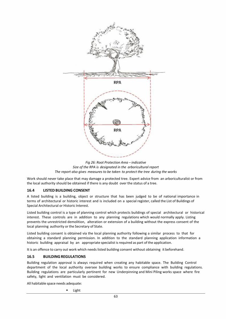
63
Fig 26: Root Protection Area – indicative Size of the RPA is designated in the arboricultural report
The report also gives measures to be taken to protect the tree during the works
Work should never take place that may damage a protected tree. Expert advice from an arboriculturalist or from the local authority should be obtained if there is any doubt over the status of a tree.
16.4 LISTED BUILDING CONSENT
A listed building is a building, object or structure that has been judged to be of national importance in terms of architectural or historic interest and is included on a special register, called the List of Buildings of Special Architectural or Historic Interest.
Listed building control is a type of planning control which protects buildings of special architectural or historical interest. These controls are in addition to any planning regulations which would normally apply. Listing prevents the unrestricted demolition, alteration or extension of a building without the express consent of the local planning authority or the Secretary of State.
Listed building consent is obtained via the local planning authority following a similar process to that for obtaining a standard planning permission. In addition to the standard planning application information a historic building appraisal by an appropriate specialist is required as part of the application.
It is an offence to carry out work which needs listed building consent without obtaining it beforehand.
16.5 BUILDING REGULATIONS
Building regulation approval is always required when creating any habitable space. The Building Control department of the local authority oversee building works to ensure compliance with building regulations. Building regulations are particularly pertinent for new Underpinning and Mini Piling works space where fire safety, light and ventilation must be considered.
All habitable space needs adequate:
Light
64
Ventilation
Fire safety measures
Natural light is preferable for living space but it is not a requirement under building regulations.
Habitable rooms can be ventilated by natural or mechanical means so this should not be restrictive but it does need to be considered.
Fire safety measures include escape routes to prevent occupants being trapped in the event of fire. This is particularly important in Underpinning and Mini Piling works design where access can be restricted.
There must usually be at least two routes in and out. Often the second route will be an emergency only route via steps or ladders in a lightwell.
Measures such as internal fire suppression (sprinklers designed for residential use) and emergency fire curtains can be used where only one route in and out is possible.
The fire safety plan must be approved by Building Control. The plan should be thought through early and outline approval gained from Building Control as making changes once construction has started can be difficult and expensive.
16.6 HEALTH AND SAFETY
A property owner is not expected to oversee directly or be responsible for health and safety on site. However the employer sets the tone for how the project is undertaken. The most important decision taken by the home owner is to instruct responsible and competent designers and contractors.
Instructing the lowest cost contractor will often mean instructing the contractor with the least care for health and safety including a disregard for correct temporary works and the structural stability of existing buildings.
It is reasonable to expect the contractor to explain how they will approach the various items that have been covered in the health and safety section of this document as well as going to one or two of their current live construction phase sites to assess how health and safety aspects are approached.
16.7 IMPACT ON NEIGHBOURS
Underpinning and Mini Piling works projects are likely to have a negative impact on neighbours even when well managed. Activities like breaking out concrete or brickwork and cutting steel are noisy. Digging and demolition will create some dust and vibration.
A good neighbour should consider measures to reduce negative construction impact possibly including:
Giving advance notice of the start date and duration of work
Communicating with neighbours during the project
Asking contractors to communicate directly with neighbours
Notifying in advance periods of particularly noisy work
Agreeing the timing of the project with neighbours to suite periods when neighbours may be away or delaying a project start to allow children's exam periods to be finished
Limiting noisy working hours
It should be remembered that anything that causes work to be slowed will increase project duration and cost.
There are unfortunately no perfect answers to this matter and each situation needs to be considered specifically. In general early communication with neighbours will be better received and have a better outcome for all rather than moving forward without any interaction.
17. LIST OF APPENDICES
Appendix A - Site investigations
Appendix B - Building damage classification
Appendix C - Safety hazards and mitigating actions
Appendix D - Health hazards and mitigating actions
Appendix E - Planning for risk management - detail on information required
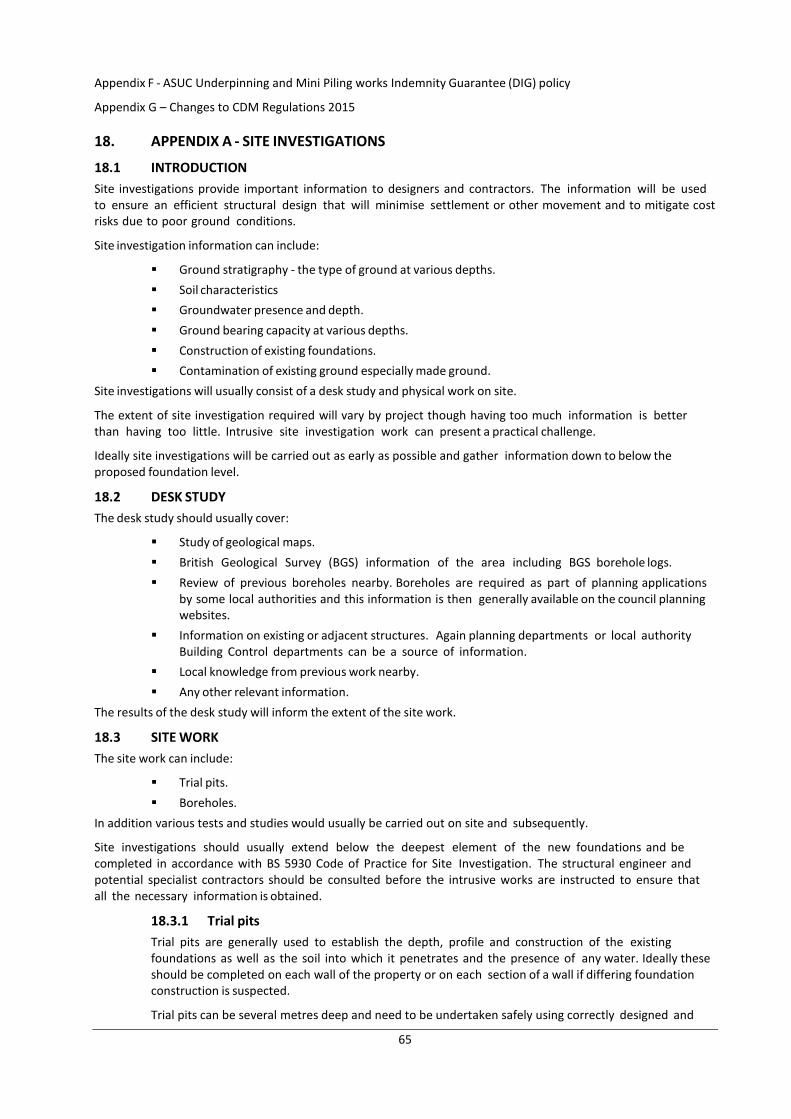
65
Appendix F - ASUC Underpinning and Mini Piling works Indemnity Guarantee (DIG) policy
Appendix G – Changes to CDM Regulations 2015
18. APPENDIX A - SITE INVESTIGATIONS
18.1 INTRODUCTION
Site investigations provide important information to designers and contractors. The information will be used to ensure an efficient structural design that will minimise settlement or other movement and to mitigate cost risks due to poor ground conditions.
Site investigation information can include:
Ground stratigraphy - the type of ground at various depths.
Soil characteristics
Groundwater presence and depth.
Ground bearing capacity at various depths.
Construction of existing foundations.
Contamination of existing ground especially made ground.
Site investigations will usually consist of a desk study and physical work on site.
The extent of site investigation required will vary by project though having too much information is better than having too little. Intrusive site investigation work can present a practical challenge.
Ideally site investigations will be carried out as early as possible and gather information down to below the proposed foundation level.
18.2 DESK STUDY
The desk study should usually cover:
Study of geological maps.
British Geological Survey (BGS) information of the area including BGS borehole logs.
Review of previous boreholes nearby. Boreholes are required as part of planning applications by some local authorities and this information is then generally available on the council planning websites.
Information on existing or adjacent structures. Again planning departments or local authority Building Control departments can be a source of information.
Local knowledge from previous work nearby.
Any other relevant information.
The results of the desk study will inform the extent of the site work.
18.3 SITE WORK
The site work can include:
Trial pits.
Boreholes.
In addition various tests and studies would usually be carried out on site and subsequently.
Site investigations should usually extend below the deepest element of the new foundations and be completed in accordance with BS 5930 Code of Practice for Site Investigation. The structural engineer and potential specialist contractors should be consulted before the intrusive works are instructed to ensure that all the necessary information is obtained.
18.3.1 Trial pits
Trial pits are generally used to establish the depth, profile and construction of the existing foundations as well as the soil into which it penetrates and the presence of any water. Ideally these should be completed on each wall of the property or on each section of a wall if differing foundation construction is suspected.
Trial pits can be several metres deep and need to be undertaken safely using correctly designed and
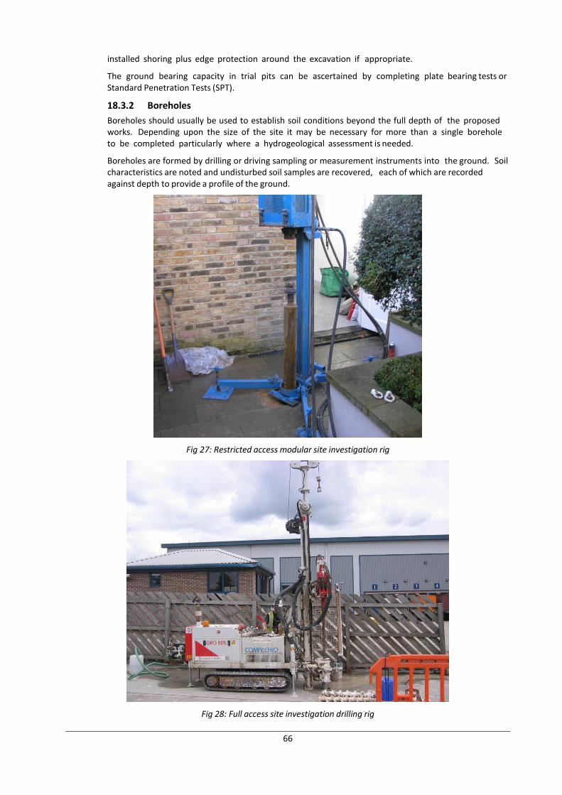
66
installed shoring plus edge protection around the excavation if appropriate.
The ground bearing capacity in trial pits can be ascertained by completing plate bearing tests or Standard Penetration Tests (SPT).
18.3.2 Boreholes
Boreholes should usually be used to establish soil conditions beyond the full depth of the proposed works. Depending upon the size of the site it may be necessary for more than a single borehole to be completed particularly where a hydrogeological assessment is needed.
Boreholes are formed by drilling or driving sampling or measurement instruments into the ground. Soil characteristics are noted and undisturbed soil samples are recovered, each of which are recorded against depth to provide a profile of the ground.
Fig 27: Restricted access modular site investigation rig
Fig 28: Full access site investigation drilling rig
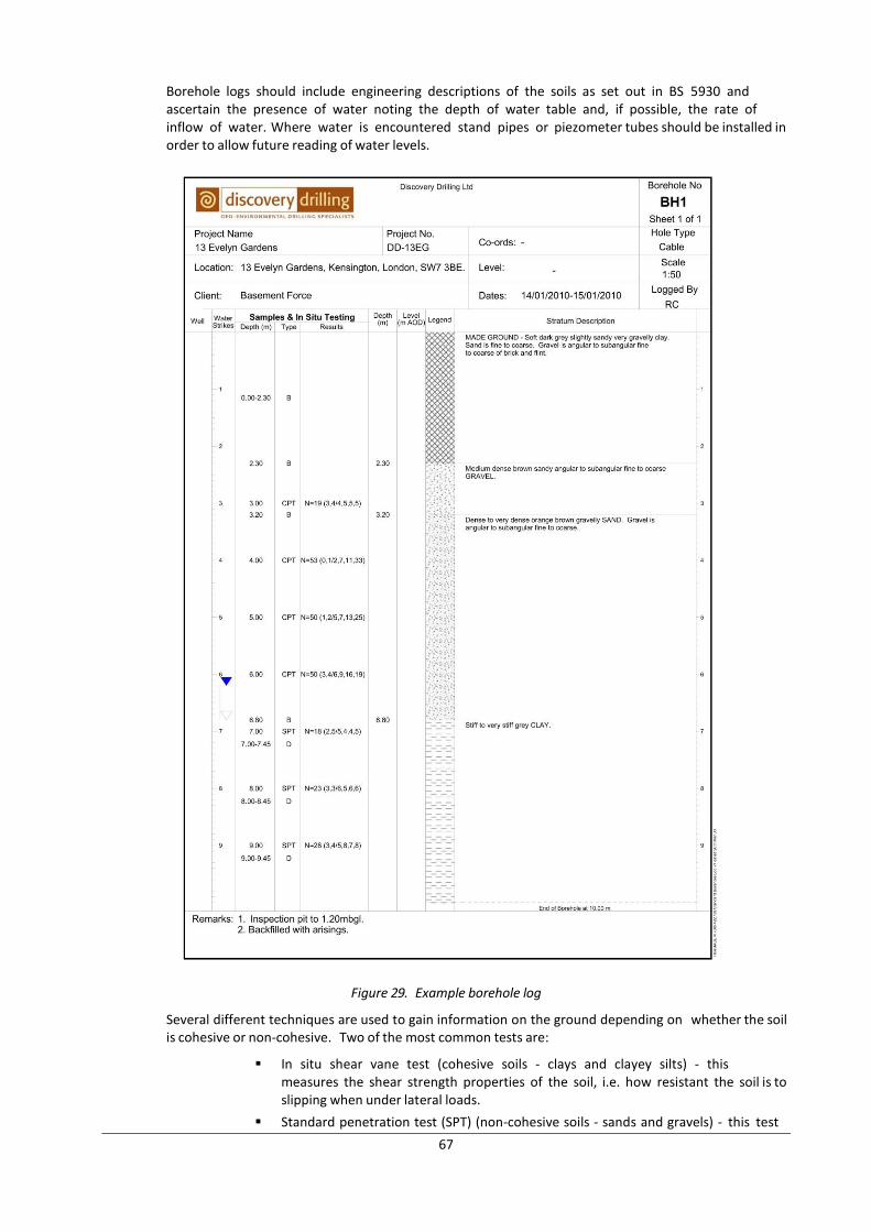
67
Borehole logs should include engineering descriptions of the soils as set out in BS 5930 and ascertain the presence of water noting the depth of water table and, if possible, the rate of inflow of water. Where water is encountered stand pipes or piezometer tubes should be installed in order to allow future reading of water levels.
Figure 29. Example borehole log
Several different techniques are used to gain information on the ground depending on whether the soil is cohesive or non-cohesive. Two of the most common tests are:
In situ shear vane test (cohesive soils - clays and clayey silts) - this measures the shear strength properties of the soil, i.e. how resistant the soil is to slipping when under lateral loads.
Standard penetration test (SPT) (non-cohesive soils - sands and gravels) - this test
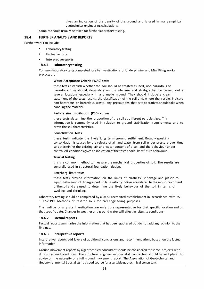
68
gives an indication of the density of the ground and is used in many empirical geotechnical engineering calculations.
Samples should usually be taken for further laboratory testing.
18.4 FURTHER ANALYSIS AND REPORTS
Further work can include:
Laboratory testing.
Factual reports
Interpretive reports
18.4.1 Laboratory testing
Common laboratory tests completed for site investigations for Underpinning and Mini Piling works projects are:
Waste Acceptance Criteria (WAC) tests
these tests establish whether the soil should be treated as inert, non-hazardous or hazardous. They should, depending on the site size and stratigraphy, be carried out at several locations especially in any made ground. They should include a clear statement of the tests results, the classification of the soil and, where the results indicate non-hazardous or hazardous waste, any precautions that site operatives should take when handling the material.
Particle size distribution (PSD) curves
these tests determine the proportion of the soil at different particle sizes. This information is commonly used in relation to ground stabilisation requirements and to prove the soil characteristics.
Consolidation tests
these tests indicate the likely long term ground settlement. Broadly speaking consolidation is caused by the release of air and water from soil under pressure over time so determining the existing air and water content of a soil and the behaviour under controlled conditions gives an indication of the tested soils likely future behaviour.
Triaxial testing
this is a common method to measure the mechanical properties of soil. The results are generally used in structural foundation design.
Atterberg limit tests
these tests provide information on the limits of plasticity, shrinkage and plastic to liquid behaviour of fine-grained soils. Plasticity indices are related to the moisture content of the soil and are used to determine the likely behaviour of the soil in terms of swelling and shrinking.
Laboratory testing should be completed by a UKAS accredited establishment in accordance with BS 1377-2 1990 Methods of test for soils for civil engineering purposes.
The findings of any site investigation are only truly representative for that specific location and on that specific date. Changes in weather and ground water will affect in situ site conditions.
18.4.2 Factual reports
Factual reports summarise the information that has been gathered but do not add any opinion to the findings.
18.4.3 Interpretive reports
Interpretive reports add layers of additional conclusions and recommendations based on the factual information.
Ground movement reports by a geotechnical consultant should be considered for some projects with difficult ground conditions. The structural engineer or specialist contractors should be well placed to advise on the necessity of a full ground movement report. The Association of Geotechnical and Geoenvironmental Specialists is a good source for a suitable geotechnical consultant.
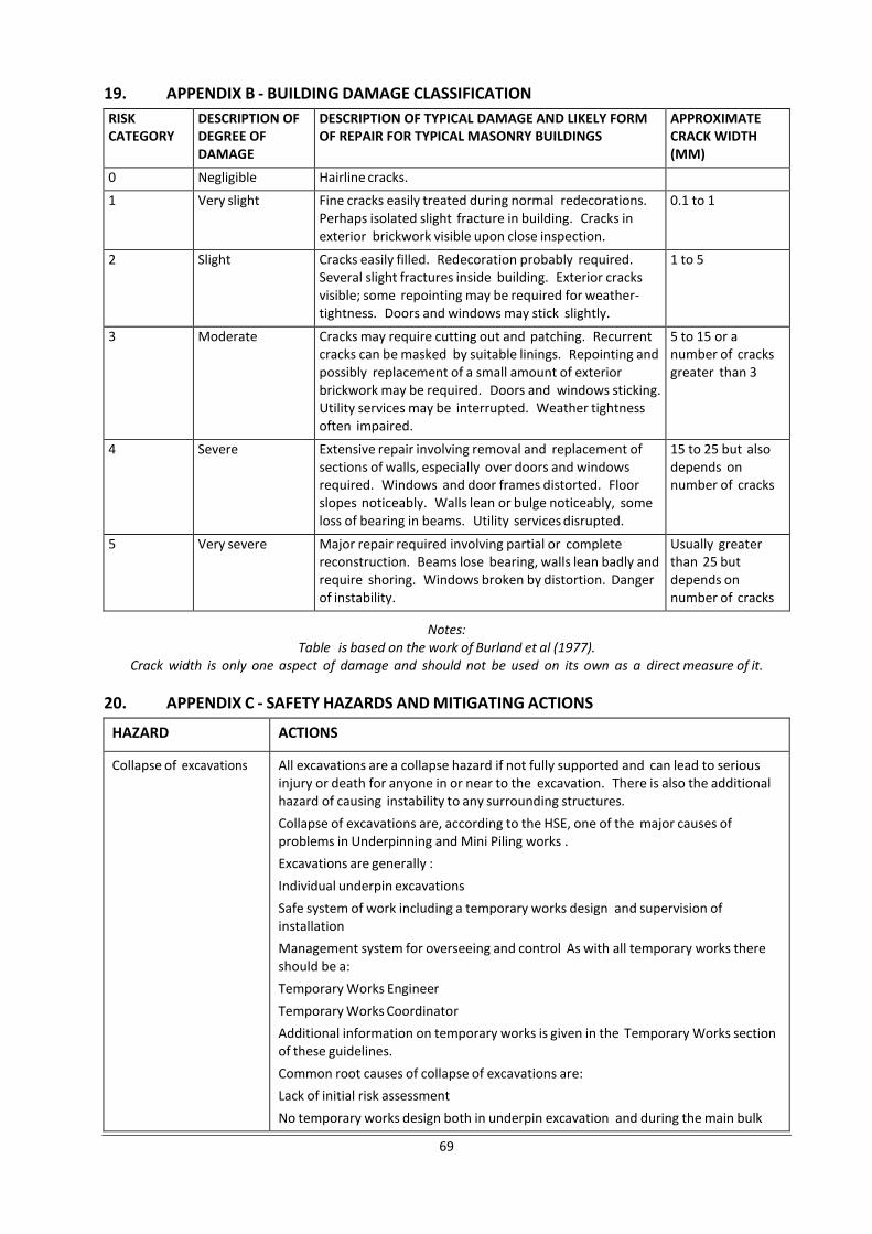
69
19. APPENDIX B - BUILDING DAMAGE CLASSIFICATION
RISK CATEGORY
DESCRIPTION OF DEGREE OF DAMAGE
DESCRIPTION OF TYPICAL DAMAGE AND LIKELY FORM OF REPAIR FOR TYPICAL MASONRY BUILDINGS
APPROXIMATE CRACK WIDTH (MM)
0 Negligible Hairline cracks.
1 Very slight Fine cracks easily treated during normal redecorations. Perhaps isolated slight fracture in building. Cracks in exterior brickwork visible upon close inspection.
0.1 to 1
2 Slight Cracks easily filled. Redecoration probably required. Several slight fractures inside building. Exterior cracks visible; some repointing may be required for weather- tightness. Doors and windows may stick slightly.
1 to 5
3 Moderate Cracks may require cutting out and patching. Recurrent cracks can be masked by suitable linings. Repointing and possibly replacement of a small amount of exterior brickwork may be required. Doors and windows sticking. Utility services may be interrupted. Weather tightness often impaired.
5 to 15 or a number of cracks greater than 3
4 Severe Extensive repair involving removal and replacement of sections of walls, especially over doors and windows required. Windows and door frames distorted. Floor slopes noticeably. Walls lean or bulge noticeably, some loss of bearing in beams. Utility services disrupted.
15 to 25 but also depends on number of cracks
5 Very severe Major repair required involving partial or complete reconstruction. Beams lose bearing, walls lean badly and require shoring. Windows broken by distortion. Danger of instability.
Usually greater than 25 but depends on number of cracks
Notes: Table is based on the work of Burland et al (1977).
Crack width is only one aspect of damage and should not be used on its own as a direct measure of it.
20. APPENDIX C - SAFETY HAZARDS AND MITIGATING ACTIONS
HAZARD ACTIONS
Collapse of excavations All excavations are a collapse hazard if not fully supported and can lead to serious injury or death for anyone in or near to the excavation. There is also the additional hazard of causing instability to any surrounding structures.
Collapse of excavations are, according to the HSE, one of the major causes of problems in Underpinning and Mini Piling works .
Excavations are generally :
Individual underpin excavations
Safe system of work including a temporary works design and supervision of installation
Management system for overseeing and control As with all temporary works there should be a:
Temporary Works Engineer
Temporary Works Coordinator
Additional information on temporary works is given in the Temporary Works section of these guidelines.
Common root causes of collapse of excavations are:
Lack of initial risk assessment
No temporary works design both in underpin excavation and during the main bulk
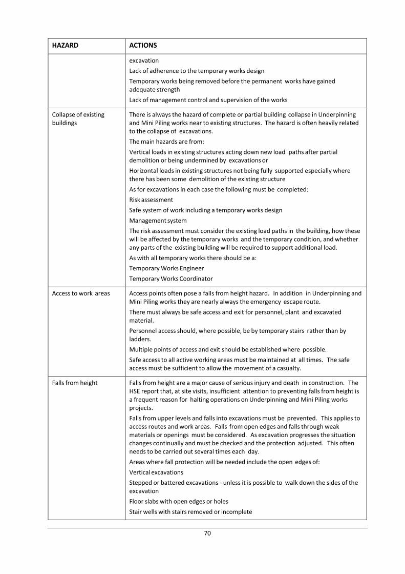
70
HAZARD ACTIONS
excavation
Lack of adherence to the temporary works design
Temporary works being removed before the permanent works have gained adequate strength
Lack of management control and supervision of the works
Collapse of existing buildings
There is always the hazard of complete or partial building collapse in Underpinning and Mini Piling works near to existing structures. The hazard is often heavily related to the collapse of excavations.
The main hazards are from:
Vertical loads in existing structures acting down new load paths after partial demolition or being undermined by excavations or
Horizontal loads in existing structures not being fully supported especially where there has been some demolition of the existing structure
As for excavations in each case the following must be completed:
Risk assessment
Safe system of work including a temporary works design
Management system
The risk assessment must consider the existing load paths in the building, how these will be affected by the temporary works and the temporary condition, and whether any parts of the existing building will be required to support additional load.
As with all temporary works there should be a:
Temporary Works Engineer
Temporary Works Coordinator
Access to work areas Access points often pose a falls from height hazard. In addition in Underpinning and Mini Piling works they are nearly always the emergency escape route.
There must always be safe access and exit for personnel, plant and excavated material.
Personnel access should, where possible, be by temporary stairs rather than by ladders.
Multiple points of access and exit should be established where possible.
Safe access to all active working areas must be maintained at all times. The safe access must be sufficient to allow the movement of a casualty.
Falls from height Falls from height are a major cause of serious injury and death in construction. The HSE report that, at site visits, insufficient attention to preventing falls from height is a frequent reason for halting operations on Underpinning and Mini Piling works projects.
Falls from upper levels and falls into excavations must be prevented. This applies to access routes and work areas. Falls from open edges and falls through weak materials or openings must be considered. As excavation progresses the situation changes continually and must be checked and the protection adjusted. This often needs to be carried out several times each day.
Areas where fall protection will be needed include the open edges of:
Vertical excavations
Stepped or battered excavations - unless it is possible to walk down the sides of the excavation
Floor slabs with open edges or holes
Stair wells with stairs removed or incomplete
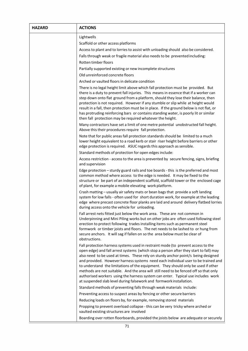
71
HAZARD ACTIONS
Lightwells
Scaffold or other access platforms
Access to plant and to lorries to assist with unloading should also be considered.
Falls through weak or fragile material also needs to be prevented including:
Rotten timber floors
Partially supported existing or new incomplete structures
Old unreinforced concrete floors
Arched or vaulted floors in delicate condition
There is no legal height limit above which fall protection must be provided. But there is a duty to prevent fall injuries. This means in essence that if a worker can step down onto flat ground from a platform, should they lose their balance, then protection is not required. However if any stumble or slip while at height would result in a fall, then protection must be in place. If the ground below is not flat, or has protruding reinforcing bars or contains standing water, is poorly lit or similar then fall protection may be required whatever the height.
Many contractors have set a limit of one metre potential unobstructed fall height. Above this their procedures require fall protection.
Note that for public areas fall protection standards should be limited to a much lower height equivalent to a road kerb or stair riser height before barriers or other edge protection is required. ASUC regards this approach as sensible.
Standard methods of protection for open edges include:
Access restriction - access to the area is prevented by secure fencing, signs, briefing and supervision
Edge protection – sturdy guard rails and toe boards - this is the preferred and most common method where access to the edge is needed. It may be fixed to the structure or be part of an independent scaffold, scaffold tower or the enclosed cage of plant, for example a mobile elevating work platform.
Crash matting – usually air safety mats or bean bags that provide a soft landing system for low falls - often used for short duration work, for example at the leading edge where precast concrete floor planks are laid and around delivery flatbed lorries during access onto the vehicle for unloading.
Fall arrest nets fitted just below the work area. These are not common in Underpinning and Mini Piling works but on other jobs are often used following steel erection to protect following trades installing items such as permanent steel formwork or timber joists and floors. The net needs to be lashed to or hung from secure anchors. It will sag if fallen on so the area below must be clear of obstructions.
Fall protection harness systems used in restraint mode (to prevent access to the open edge) and fall arrest systems (which stop a person after they start to fall) may also need to be used at times. These rely on sturdy anchor point/s being designed and provided. However harness systems need each individual user to be trained and to understand the limitations of the equipment. They should only be used if other methods are not suitable. And the area will still need to be fenced off so that only authorised workers using the harness system can enter. Typical use includes work at suspended slab level during falsework and formwork installation.
Standard methods of preventing falls through weak materials include:
Preventing access to suspect areas by fencing or other secure barriers
Reducing loads on floors by, for example, removing stored materials
Propping to prevent overload collapse - this can be very tricky where arched or vaulted existing structures are involved
Boarding over rotten floorboards, provided the joists below are adequate or securely
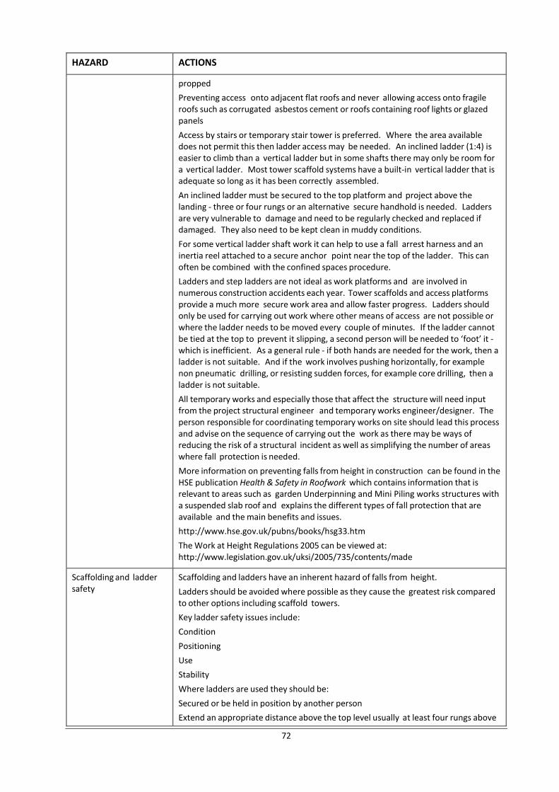
72
HAZARD ACTIONS
propped
Preventing access onto adjacent flat roofs and never allowing access onto fragile roofs such as corrugated asbestos cement or roofs containing roof lights or glazed panels
Access by stairs or temporary stair tower is preferred. Where the area available does not permit this then ladder access may be needed. An inclined ladder (1:4) is easier to climb than a vertical ladder but in some shafts there may only be room for a vertical ladder. Most tower scaffold systems have a built-in vertical ladder that is adequate so long as it has been correctly assembled.
An inclined ladder must be secured to the top platform and project above the landing - three or four rungs or an alternative secure handhold is needed. Ladders are very vulnerable to damage and need to be regularly checked and replaced if damaged. They also need to be kept clean in muddy conditions.
For some vertical ladder shaft work it can help to use a fall arrest harness and an inertia reel attached to a secure anchor point near the top of the ladder. This can often be combined with the confined spaces procedure.
Ladders and step ladders are not ideal as work platforms and are involved in numerous construction accidents each year. Tower scaffolds and access platforms provide a much more secure work area and allow faster progress. Ladders should only be used for carrying out work where other means of access are not possible or where the ladder needs to be moved every couple of minutes. If the ladder cannot be tied at the top to prevent it slipping, a second person will be needed to ‘foot’ it - which is inefficient. As a general rule - if both hands are needed for the work, then a ladder is not suitable. And if the work involves pushing horizontally, for example non pneumatic drilling, or resisting sudden forces, for example core drilling, then a ladder is not suitable.
All temporary works and especially those that affect the structure will need input from the project structural engineer and temporary works engineer/designer. The person responsible for coordinating temporary works on site should lead this process and advise on the sequence of carrying out the work as there may be ways of reducing the risk of a structural incident as well as simplifying the number of areas where fall protection is needed.
More information on preventing falls from height in construction can be found in the HSE publication Health & Safety in Roofwork which contains information that is relevant to areas such as garden Underpinning and Mini Piling works structures with a suspended slab roof and explains the different types of fall protection that are available and the main benefits and issues.
http://www.hse.gov.uk/pubns/books/hsg33.htm
The Work at Height Regulations 2005 can be viewed at: http://www.legislation.gov.uk/uksi/2005/735/contents/made
Scaffolding and ladder safety
Scaffolding and ladders have an inherent hazard of falls from height.
Ladders should be avoided where possible as they cause the greatest risk compared to other options including scaffold towers.
Key ladder safety issues include:
Condition
Positioning
Use
Stability
Where ladders are used they should be:
Secured or be held in position by another person
Extend an appropriate distance above the top level usually at least four rungs above
73
HAZARD ACTIONS
the uppermost access level or have an alternative secure handhold above the upper platform level
Be protected at the access point to prevent a fall from height ideally with a sprung gate
Ladders can be used to work from if more suitable work equipment is not justified because of the low risk and short duration of the work. Short duration is normally seen as being between 15 and 30 minutes.
Key tower scaffold safety issues are:
Erection and dismantling
Stability
Precautions and inspection
Using and moving Tower use requires:
That the tower be suitable for the work
Be erected and dismantled by people who have been trained and are competent to do so
Users to know the potential dangers
Users to know the appropriate safety precautions required
Proper management and rigorous scaffold inspection Tube and fitting scaffold should be installed by a reputable scaffolding company who use trained operatives. Once installed the scaffold should be inspected and maintained regularly.
Existing services Existing services present a major hazard and can cause explosions, fire, flash fires, and burns. Each year damage to services during construction work is responsible for severe injuries and fatalities.
Existing services (gas, electricity, water, sewer, telecom, other) must be located and precautions established to prevent damage and avoid danger.
Plans of the main services should be obtained from the relevant utility companies.
On site:
Use of locating devices prior to excavation: Hum detectors, radio frequency detectors, transmitter-receiver instruments, metal detectors and ground probing radar should be considered
Services should be assumed as live unless confirmed otherwise
Careful hand excavation (not using hand power tools and not using pointed tools) should be used to prove the location of existing services in line with HSE HGS 47
Other tools and plant should not be used within 500mm of service locations
Services encased in concrete will need to be disconnected or at least isolated whilst being exposed
Safe methods of excavation around services include water jetting or high-velocity air jets should be considered
Unknown services should be treated as follows:
Black - electrical
Yellow - gas
Iron and steel pipes - gas
Operatives should know the modern national colour coding system for buried services
Black - electricity
Red - electricity; some high voltage cables
Orange - street lighting in England and Wales
74
HAZARD ACTIONS
Yellow - gas
Blue - Water
Grey or white - telecommunications
Green - cable television and some telecommunications
Overhead power lines should also be identified and the risk assessed. Collection and delivery vehicle sizes should be noted as well as the likely range of movement of the grab arms of muck away lorries.
Electrical handheld power tools
Electrical power creates hazard from burns and shocks.
230 / 240 volt mains power should be discouraged and should not be used directly for tools on site. Where 230 volt power is used, for example in welfare facilities and site offices, residual current or ‘trip’ devices (RCDs) must be installed.
Cordless or 110 volt tools should be used where possible as they are unlikely to cause a fatal shock. The 110 volt transformer should connect to a dry 230 volt supply well away from the work area.
High power tool batteries must be kept in dry conditions. Immersion can lead to sudden discharge, overheating and explosion.
Mobile plant safety Mobile plant can cause serious injury or death by collision, crushing and overturning. The hazard is to site operatives and to members of the public.
Plant most often used are:
Excavators / diggers
Piling rigs
Dump trucks and barrows
Telescopic handlers
Common general control measures are:
Segregation of vehicles and pedestrians; movement routes and exclusion zones
Maintenance of clear 360o visibility
Use limited to trained and competent staff
Use of signallers and banksmen
Use of well maintained machines that are regularly inspected, serviced and maintained
Speed limits
Levelling of ground to reduce risk of overturning
Use of stop blocks at edges
Use of load spreading pads or a designed platform for high centre of gravity plant
Confined spaces A confined space is any area of an enclosed nature where there is a risk of death or serious injury from hazardous substances or dangerous conditions.
Dangers in confined spaces can arise from:
Lack of oxygen
Poisonous gas, fume or vapour
Liquids and solids which can suddenly fill the space or release gases into it when disturbed
Fire and explosions
Dust present in high concentrations
Hot conditions leading to a dangerous increase in body temperature
The hazard is high in below ground areas with poor natural ventilation such as
75
HAZARD ACTIONS
tunnels, excavations as well as in any enclosed space. Air quality may be reduced by a slight reduction in proportion of oxygen or by the presence of a harmful gas. This can affect people without warning – i.e. no smell, taste or unwell feeling.
There is a history of multiple deaths where one person goes into a confined space to rescue someone who has collapsed. The rescuer is also overcome and others attempt to assist.
Assessment, planning and strict procedures are needed to ensure this scenario cannot happen. Work in confined spaces should be designed out where possible.
A ground survey, a check for contamination, and knowledge of the site history and local area may help identify sites at risk.
The best control measure is to have good natural ventilation. This may need to be supplemented by forced ventilation. In some cases fresh air may need to be ducted into remote areas.
In the extreme – e.g. below ground live sewer connections - it may be necessary to use confined space trained workers equipped with breathing apparatus and rescue equipment. In these cases the working person will be attached to a lifeline with means to pull/lift a person to fresh air and with an outside team always present.
Tunnel working may require air monitoring equipment in the tunnel that will alarm if a specified gas is detected or the oxygen level drops. Underground workers on tunnelling projects should also carry a rescue set that provides enough oxygen to allow them to escape if the air monitoring alarm goes off.
All work areas must be assessed to decide if the area is to be regarded as a ‘confined space’. For all confined spaces a system of work for entry, exit and work in the space must be established. Fume extractors, clean air, and multiple access and egress points should be considered. An emergency rescue plan must be developed, communicated to all relevant persons and practiced on site including a safe system of recovery.
Only trained and competent operatives should work in confined spaces.
Fire and means of escape
Fire on an Underpinning and Mini Piling works site has a high hazard of serious injury or death with the likely causes being asphyxiation, choking or burns.
The causes of fire must be managed including:
Minimising the amount of flammable material on site including any solvent based paints and thinners, petrol, LPG, oxyacetylene sets, etc. These are all particularly high fire hazards.
Minimising the amount of combustible material on site at any one time - especially combustible foam, cardboard, thin timber sheet materials etc.
Fuels being stored outside the fire risk areas
Control of hot works and other ignition sources such as grinding steel
All sites must have a fire plan and arrangements covering:
Fire alarms
Fire fighting equipment, generally fire extinguishers, at each level or in each working area
Safe means of escape
Completed regular fire plan drills
Flammable materials should be stored outside where possible in a ventilated cabinet or cage.
The risk of fuel fumes that are heavier than air collecting in excavations should be remembered
Dangerous substances Dangerous substances cause a hazard of explosion, burns, asphyxiation, choking and
76
HAZARD ACTIONS
poisoning.
All dangerous substances such as fuels, paints, solvents, foam filler with flammable propellant, gas welding sets, LPG heaters and bottles etc. must be risk assessed and appropriate precautions be taken to protect people and the environment.
Safe methods must be established and enforced covering:
Storage - solvents should be kept separately from combustibles. LPG and acetylene should be kept completely separately.
Refuelling of petrol equipment including hand held tools must be carried out outside in open air
The risk from the collection or movement of heavier than air gases and fumes should be remembered
Lifting operations Mobile crane operations have a hazard of overturning and dropping of loads. The hazard is to operatives and to members of the public especially during deliveries and collections.
All mobile crane operations, including lorry loader crane deliveries, must be properly planned and have a lifting plan in place before the work starts. The work must be supervised to ensure proper implementation of the lifting plan.
For larger lifting operations a temporary works engineer will need to advise on ground conditions to ensure that any crane is not vulnerable to overturn.
Lighting Poor site lighting increases the likelihood of injury across multiple other areas.
All work areas, access and egress walkways and passageways must be adequately and safely lit at all times.
Provision of torches or automatic back up lighting should be made to cover for a failure in the main works lighting. Where the site requires temporary lighting this should include battery backup emergency lighting particularly on emergency exit routes.
General site order and slips, trips and falls on the same level
Sites in a poor general condition create an increased hazard for general injuries such as cuts, bruises and impalement.
Mitigating actions include:
Use of protective caps on exposed reinforcement ends to prevent impalement
Use of continuity reinforcement strips to reduce the amount of open-ended reinforcement exposed to reduce impalement hazard
Removal of nails and screws from timber including from dismantled formwork
Marking the ends of steelwork, temporary works, props or similar protruding elements with high visibility material or paint
Removing the sharp edges of scaffold, steel, temporary works, edge protection and scaffold gates to reduce the likelihood of cuts and abrasions
Slips, trips and falls on the same level may appear minor hazards but can lead to serious injury or in some circumstances to fatalities.
Common occurrences on construction sites which cause slips, trips and falls include:
Poorly stacked or located equipment and waste materials
Uneven surfaces
Obstacles created during the construction or demolition process
Trailing cables
Wet or slippery surfaces
Changes in level
Anyone in control of a construction site must manage work so that people can move safely around the site. The site must be kept in a clean and orderly condition in
77
HAZARD ACTIONS
order to reduce the chance of injury through slips, trips and falls.
Clear walkways are essential in order to maintain safe movement.
21. APPENDIX D - HEALTH HAZARDS AND MITIGATING ACTIONS
HAZARD ACTIONS
Asbestos Exposure to asbestos is the single largest cause of death in the construction industry.
Exposure to asbestos is a serious health hazard with exposure to tiny amounts of asbestos being able to cause death or serious injury.
An intrusive asbestos survey should be carried out prior to the main works, including any soft strip, on buildings built before about 1990. Practically this cannot be completed to areas that are to be excavated but where possible checks should be made under suspended ground or lowest floors which should consider whether there are any subfloor ducts etc. or whether concrete floors have been cast onto asbestos containing formwork.
The survey should identify and locate any asbestos containing materials (ACMs). In the event that ACMs are identified then all work must be undertaken in line with asbestos work regulations.
Asbestos containing materials that are bound in a matrix, for example asbestos cement such as corrugated roof sheeting and plasterboard coated in textured coatings such as Artex can, legally, be removed by general contractors. Anyone who is asked to remove these items must know the correct methods of removing and handling the product, which is mainly based on damping down and removing whole with minimal breakage.
Many asbestos containing materials can only be removed by a contractor licensed to work with asbestos.
In the event that a licensed contractor is required to remove asbestos then an asbestos clearance certificate and the original survey must be obtained from the specialist asbestos contractor before general construction work starts and the clearance certificate and original survey must be made available to all parties.
All staff who might come across asbestos in the course of their work are required to complete asbestos awareness training. It is a legal requirement that workers know about the health risks from asbestos, how to identify asbestos and what to do if they uncover or damage asbestos.
Once construction work is finished, information may need to be communicated about the location and condition of any asbestos that is still within the premises. This is so that the client can comply with their duty to manage asbestos in non-domestic premises.
Hazardous substances and processes
Hazardous substances and processes both present a hazard to health and must be managed.
All substances with the potential to be hazardous to health or those that can have significant environmental impacts must be assessed and appropriate precautions established.
This includes hazardous substances already present on site, those generated on site and those brought to site as part of the work and include:
Powder cement
Lime
Wet concrete
Paints
78
HAZARD ACTIONS
Solvents
Plant exhaust fumes
And substances that are already on site:
Asbestos
Dust containing silica
Chemical contaminants
Sewage
Pigeon droppings
Rat urine and droppings
The assessment should cover the storage and use of the chemical and identify any issues that may occur when more than one chemical are combined.
Again the priority should be:
Avoidance – lower risk alternatives should be used if possible
Action – taken to reduce risk
Information – those involved must be provided with all relevant information on the substances, the associated risks and the appropriate mitigating actions
Use of PPE, while often necessary, alone should only be used when all other practical alternatives have been considered.
Respiratory disease especially from dust containing silica
Respiratory diseases are a significant hazard in the construction sector with the most common being:
Silicosis - silicosis is second only to asbestos in the number of deaths caused in the construction industry. The health risk is from lung damage leading to cancer.
Chronic obstructive pulmonary disease
Occupational asthma
Concrete dust is generally caused by disc cutters and angle grinders. All concrete cutting that produces dust should be completed wet. Suitable respiratory protection will probably still need to be worn during and after the work.
The problem is made worse in an enclosed area.
Exposure to substances that can cause respiratory disease or breathing difficulty if inhaled must, by law, be minimised.
The means of control in priority are:
Elimination of the hazard
Suppression or extraction of the dust
Use of PPE - PPE use on its own is a last resort
All workers who might be exposed should receive clear information, instruction and appropriate training.
Carbon monoxide and other noxious gases
Site equipment using internal combustion engines as well as inadequately ventilated liquefied petroleum gas (LPG) equipment can produce carbon monoxide gas leading to low oxygen levels or to the presence of flammable gases. Other common asphyxiant gases are ethane, helium, hydrogen, methane and nitrogen. In addition inert gases such as argon, helium, nitrogen or carbon dioxide are sometimes deliberately used on site for activities such as welding purposes or in fire suppression equipment.
Underpin excavations are particularly prone to becoming oxygen depleted.
There is also a hazard from leaking underground gas mains. A mains gas leak can quickly lead to a dangerous atmosphere.
The main mitigations are:
79
HAZARD ACTIONS
Awareness
Good ventilation
Plant and equipment in good condition and properly maintained
Gas bottles stored outside and valves closed at end of shift
Gas detectors and alarms used
Generators must only be run outdoors and completely in open air
Dermatitis Contact dermatitis is inflammation of the skin that can arise from contact with a range of materials commonly used in Underpinning and Mini Piling works . The main signs and symptoms are dryness, redness, itching, swelling, flaking, cracking and blistering. Dermatitis can be painful and can require medical treatment
Dermatitis usually affects the hands and forearms, though the face, neck, chest, and legs can also be affected.
The main products that cause dermatitis are:
Wet cement
Epoxy resins and hardeners
Acrylic sealants
Bitumen or asphalt
Solvents in paints, glues or other surface coatings
Petrol
Diesel, oils and greases
The use of products known to cause dermatitis must be strictly controlled on site with adequate washing and if necessary decontamination facilities available at all times.
Correct Personal Protective Equipment (PPE) should always be used.
Damage to eyes Activities on site including breaking of concrete, grinding and cutting timber all have significant hazard of damage to eyes. While the likelihood of injury from one work action is low the damage caused to an eye from even a single minor impact can cause permanent blindness.
Correct eye protection should be worn at all times for any work activity that has a possibility of material being moved at speed into the eye.
Noise High noise levels are a hazard to hearing.
Prolonged exposure to high noise levels will cause reduction in hearing levels and eventually permanent deafness. As a guide a noise level which requires the voice to be raised in order to be heard is sufficiently loud to cause damage to hearing.
Site operatives generally do not fully appreciate the hazard and must be instructed to use correct ear protection.
Noise hazard must be assessed and any required mitigating actions identified and implemented. Where possible this should be by reducing the level and duration of noisy operations. Noise sources should, where possible, be located away from populated work areas and in particular be conducted away from welfare facilities.
Ear protection must be used by everyone in an area where there is noise at a level that might cause damage to hearing.
80
HAZARD ACTIONS
Noise is also an environmental issue which can have a serious impact on neighbours and the local community.
High levels of noise from the work can be a Statutory Nuisance (as defined in the Environmental Protection Act 1990) to the surrounding community, and in this case the local authority can limit or stop work.
Under section 60 of the Control of Pollution Act (COPA) 1974, authorities have powers to control noise (and vibration) from building sites.
Control is implemented by serving a notice on the person responsible for the construction operations. The notice can specify types of plant and machinery, permitted hours of operation, boundary noise levels and the use of 'best practicable means' to keep all noise to a minimum. For example plant and machinery used on the site shall be properly silenced and radios or other amplified music shall not be played.
Hand arm vibration Hand-arm vibration (HAV) is the health hazard associated with using handheld power tools. HAV causes serious long term health problems and disability in the hands and arms.
Hand held power tools are the main culprit - especially jack hammers, scabblers, and similar tools. Pokers, disc cutters and masonry drills can also cause HAV.
Methods of work that avoid the use of powered hand tools should be used wherever practical. For example concrete could be removed by diamond sawing or drilling and bursting to reduce the use of hand held breakers.
The system of work selected can reduce exposure to HAV. Precise formwork can reduce the need for trimming or tidying of new concrete work.
All tools used on a project should be the lowest vibration rating alternative possible with companies encouraged to adopt a low vibration purchasing policy when hiring or replacing equipment.
All operatives must be educated on the risks and symptoms of HAV and know the method and rules used to reduce HAV damage. HAV exposure should be recorded and monitored as a means of control.
All operatives should complete a pre-employment medical history questionnaire and, before working with vibrating hand tools, complete a HAV’s initial screening questionnaire.
Further screening of operatives may be required should they be identified as being susceptible to HAV or if their specific job has a high potential HAV exposure.
Manual handling and musculoskeletal disorder
Construction activities that involve manual handling present a significant hazard of musculoskeletal disorders (MSDs) and must be considered fully with action taken on three fronts:
Avoidance - manual lifting must be avoided by good design and by use of alternate systems of work such as mechanical lifting means
Action – where avoidance is not possible a system of work that minimises risk must be employed
Information – those people who carry out the manual handling must be provided with adequate information on the weight of each load, including if necessary the heaviest side of any load whose centre of gravity is not central
Staff must undertake regular appropriate training including instruction on safe handling to minimise the risk of strains and sprains.
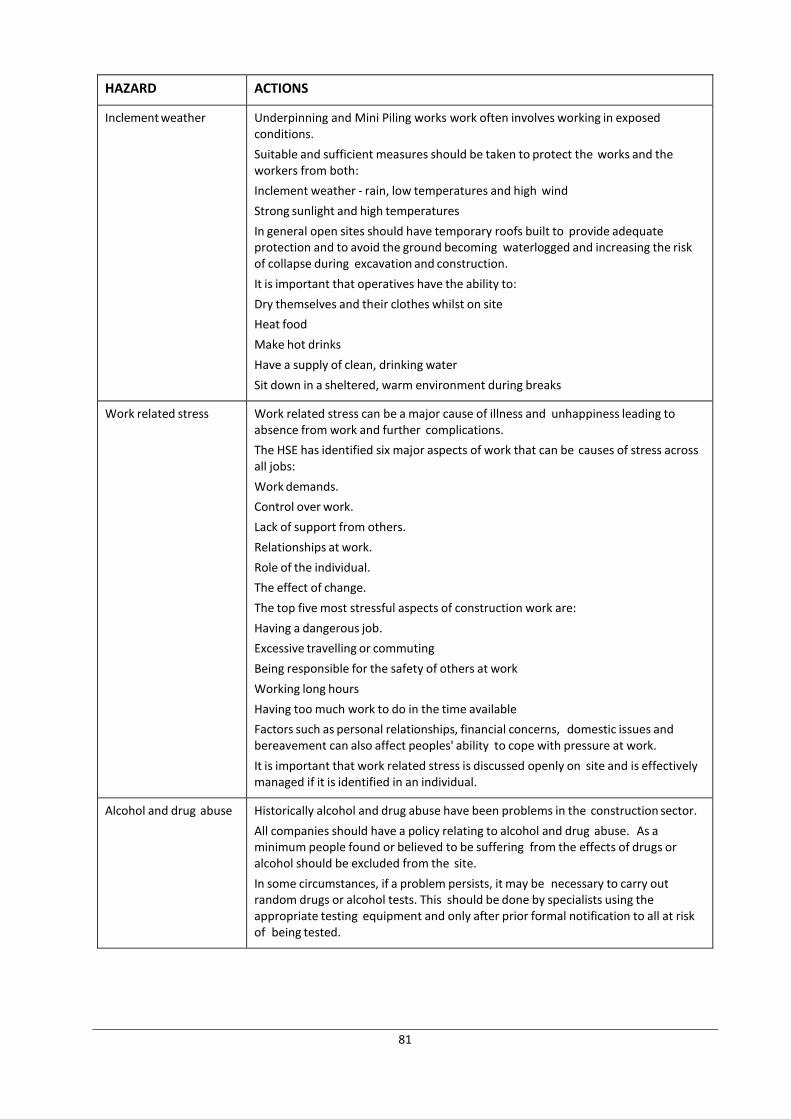
81
HAZARD ACTIONS
Inclement weather Underpinning and Mini Piling works work often involves working in exposed conditions.
Suitable and sufficient measures should be taken to protect the works and the workers from both:
Inclement weather - rain, low temperatures and high wind
Strong sunlight and high temperatures
In general open sites should have temporary roofs built to provide adequate protection and to avoid the ground becoming waterlogged and increasing the risk of collapse during excavation and construction.
It is important that operatives have the ability to:
Dry themselves and their clothes whilst on site
Heat food
Make hot drinks
Have a supply of clean, drinking water
Sit down in a sheltered, warm environment during breaks
Work related stress Work related stress can be a major cause of illness and unhappiness leading to absence from work and further complications.
The HSE has identified six major aspects of work that can be causes of stress across all jobs:
Work demands.
Control over work.
Lack of support from others.
Relationships at work.
Role of the individual.
The effect of change.
The top five most stressful aspects of construction work are:
Having a dangerous job.
Excessive travelling or commuting
Being responsible for the safety of others at work
Working long hours
Having too much work to do in the time available
Factors such as personal relationships, financial concerns, domestic issues and bereavement can also affect peoples' ability to cope with pressure at work.
It is important that work related stress is discussed openly on site and is effectively managed if it is identified in an individual.
Alcohol and drug abuse Historically alcohol and drug abuse have been problems in the construction sector.
All companies should have a policy relating to alcohol and drug abuse. As a minimum people found or believed to be suffering from the effects of drugs or alcohol should be excluded from the site.
In some circumstances, if a problem persists, it may be necessary to carry out random drugs or alcohol tests. This should be done by specialists using the appropriate testing equipment and only after prior formal notification to all at risk of being tested.
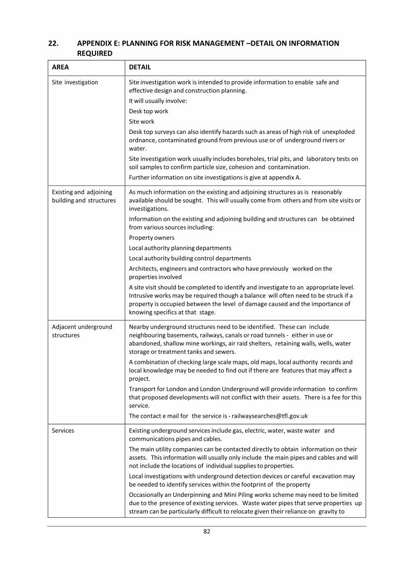
82
22. APPENDIX E: PLANNING FOR RISK MANAGEMENT –DETAIL ON INFORMATION REQUIRED
AREA DETAIL
Site investigation Site investigation work is intended to provide information to enable safe and effective design and construction planning.
It will usually involve:
Desk top work
Site work
Desk top surveys can also identify hazards such as areas of high risk of unexploded ordnance, contaminated ground from previous use or of underground rivers or water.
Site investigation work usually includes boreholes, trial pits, and laboratory tests on soil samples to confirm particle size, cohesion and contamination.
Further information on site investigations is give at appendix A.
Existing and adjoining building and structures
As much information on the existing and adjoining structures as is reasonably available should be sought. This will usually come from others and from site visits or investigations.
Information on the existing and adjoining building and structures can be obtained from various sources including:
Property owners
Local authority planning departments
Local authority building control departments
Architects, engineers and contractors who have previously worked on the properties involved
A site visit should be completed to identify and investigate to an appropriate level. Intrusive works may be required though a balance will often need to be struck if a property is occupied between the level of damage caused and the importance of knowing specifics at that stage.
Adjacent underground structures
Nearby underground structures need to be identified. These can include neighbouring basements, railways, canals or road tunnels - either in use or abandoned, shallow mine workings, air raid shelters, retaining walls, wells, water storage or treatment tanks and sewers.
A combination of checking large scale maps, old maps, local authority records and local knowledge may be needed to find out if there are features that may affect a project.
Transport for London and London Underground will provide information to confirm that proposed developments will not conflict with their assets. There is a fee for this service.
The contact e mail for the service is - [email protected]
Services Existing underground services include gas, electric, water, waste water and communications pipes and cables.
The main utility companies can be contacted directly to obtain information on their assets. This information will usually only include the main pipes and cables and will not include the locations of individual supplies to properties.
Local investigations with underground detection devices or careful excavation may be needed to identify services within the footprint of the property
Occasionally an Underpinning and Mini Piling works scheme may need to be limited due to the presence of existing services. Waste water pipes that serve properties up stream can be particularly difficult to relocate given their reliance on gravity to
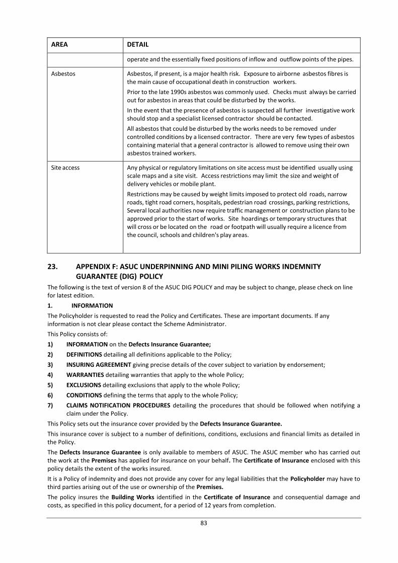
83
AREA DETAIL
operate and the essentially fixed positions of inflow and outflow points of the pipes.
Asbestos Asbestos, if present, is a major health risk. Exposure to airborne asbestos fibres is the main cause of occupational death in construction workers.
Prior to the late 1990s asbestos was commonly used. Checks must always be carried out for asbestos in areas that could be disturbed by the works.
In the event that the presence of asbestos is suspected all further investigative work should stop and a specialist licensed contractor should be contacted.
All asbestos that could be disturbed by the works needs to be removed under controlled conditions by a licensed contractor. There are very few types of asbestos containing material that a general contractor is allowed to remove using their own asbestos trained workers.
Site access Any physical or regulatory limitations on site access must be identified usually using scale maps and a site visit. Access restrictions may limit the size and weight of delivery vehicles or mobile plant.
Restrictions may be caused by weight limits imposed to protect old roads, narrow roads, tight road corners, hospitals, pedestrian road crossings, parking restrictions, Several local authorities now require traffic management or construction plans to be approved prior to the start of works. Site hoardings or temporary structures that will cross or be located on the road or footpath will usually require a licence from the council, schools and children's play areas.
23. APPENDIX F: ASUC UNDERPINNING AND MINI PILING WORKS INDEMNITY GUARANTEE (DIG) POLICY
The following is the text of version 8 of the ASUC DIG POLICY and may be subject to change, please check on line for latest edition.
1. INFORMATION
The Policyholder is requested to read the Policy and Certificates. These are important documents. If any information is not clear please contact the Scheme Administrator.
This Policy consists of:
1) INFORMATION on the Defects Insurance Guarantee;
2) DEFINITIONS detailing all definitions applicable to the Policy;
3) INSURING AGREEMENT giving precise details of the cover subject to variation by endorsement;
4) WARRANTIES detailing warranties that apply to the whole Policy;
5) EXCLUSIONS detailing exclusions that apply to the whole Policy;
6) CONDITIONS defining the terms that apply to the whole Policy;
7) CLAIMS NOTIFICATION PROCEDURES detailing the procedures that should be followed when notifying a claim under the Policy.
This Policy sets out the insurance cover provided by the Defects Insurance Guarantee.
This insurance cover is subject to a number of definitions, conditions, exclusions and financial limits as detailed in the Policy.
The Defects Insurance Guarantee is only available to members of ASUC. The ASUC member who has carried out the work at the Premises has applied for insurance on your behalf. The Certificate of Insurance enclosed with this policy details the extent of the works insured.
It is a Policy of indemnity and does not provide any cover for any legal liabilities that the Policyholder may have to third parties arising out of the use or ownership of the Premises.
The policy insures the Building Works identified in the Certificate of Insurance and consequential damage and costs, as specified in this policy document, for a period of 12 years from completion.
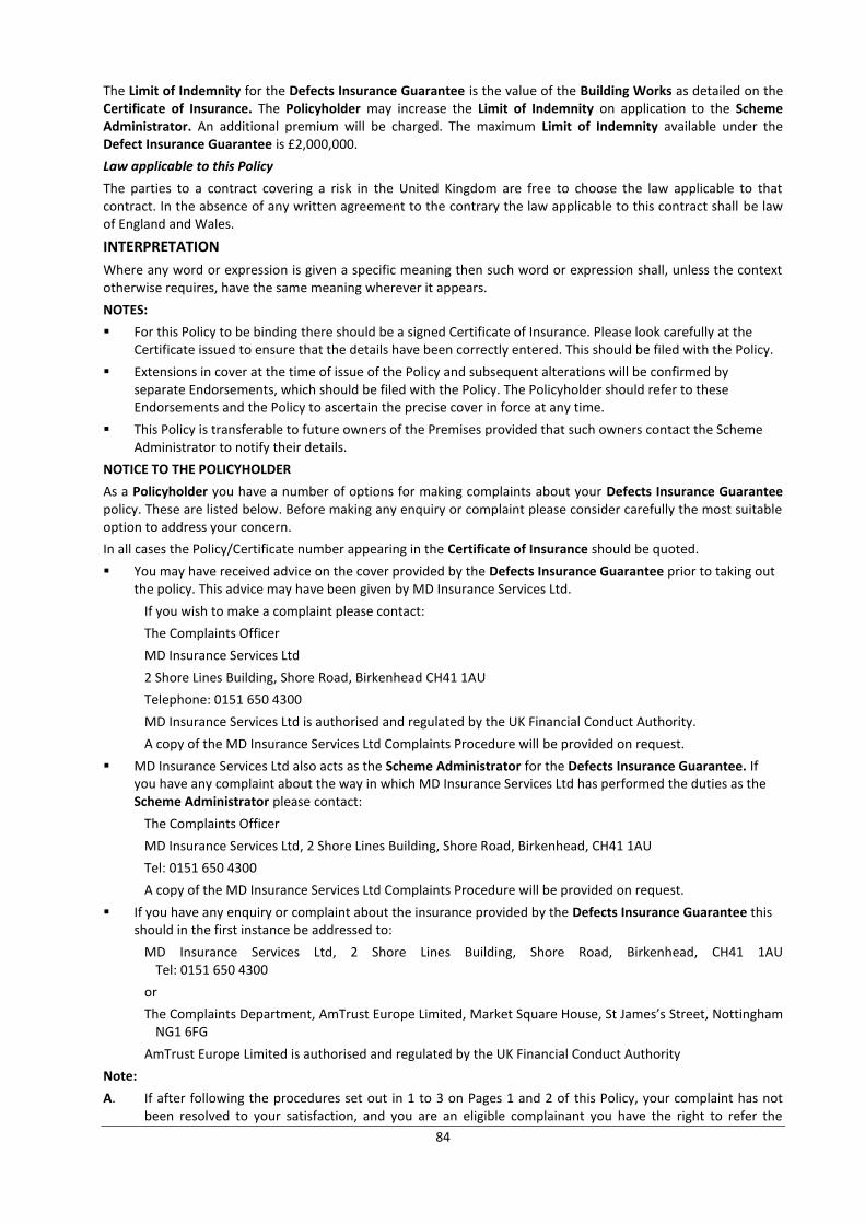
84
The Limit of Indemnity for the Defects Insurance Guarantee is the value of the Building Works as detailed on the Certificate of Insurance. The Policyholder may increase the Limit of Indemnity on application to the Scheme Administrator. An additional premium will be charged. The maximum Limit of Indemnity available under the Defect Insurance Guarantee is £2,000,000.
Law applicable to this Policy
The parties to a contract covering a risk in the United Kingdom are free to choose the law applicable to that contract. In the absence of any written agreement to the contrary the law applicable to this contract shall be law of England and Wales.
INTERPRETATION
Where any word or expression is given a specific meaning then such word or expression shall, unless the context otherwise requires, have the same meaning wherever it appears.
NOTES:
For this Policy to be binding there should be a signed Certificate of Insurance. Please look carefully at the Certificate issued to ensure that the details have been correctly entered. This should be filed with the Policy.
Extensions in cover at the time of issue of the Policy and subsequent alterations will be confirmed by separate Endorsements, which should be filed with the Policy. The Policyholder should refer to these Endorsements and the Policy to ascertain the precise cover in force at any time.
This Policy is transferable to future owners of the Premises provided that such owners contact the Scheme Administrator to notify their details.
NOTICE TO THE POLICYHOLDER
As a Policyholder you have a number of options for making complaints about your Defects Insurance Guarantee policy. These are listed below. Before making any enquiry or complaint please consider carefully the most suitable option to address your concern.
In all cases the Policy/Certificate number appearing in the Certificate of Insurance should be quoted.
You may have received advice on the cover provided by the Defects Insurance Guarantee prior to taking out the policy. This advice may have been given by MD Insurance Services Ltd.
If you wish to make a complaint please contact:
The Complaints Officer
MD Insurance Services Ltd
2 Shore Lines Building, Shore Road, Birkenhead CH41 1AU
Telephone: 0151 650 4300
MD Insurance Services Ltd is authorised and regulated by the UK Financial Conduct Authority.
A copy of the MD Insurance Services Ltd Complaints Procedure will be provided on request.
MD Insurance Services Ltd also acts as the Scheme Administrator for the Defects Insurance Guarantee. If you have any complaint about the way in which MD Insurance Services Ltd has performed the duties as the Scheme Administrator please contact:
The Complaints Officer
MD Insurance Services Ltd, 2 Shore Lines Building, Shore Road, Birkenhead, CH41 1AU
Tel: 0151 650 4300
A copy of the MD Insurance Services Ltd Complaints Procedure will be provided on request.
If you have any enquiry or complaint about the insurance provided by the Defects Insurance Guarantee this should in the first instance be addressed to:
MD Insurance Services Ltd, 2 Shore Lines Building, Shore Road, Birkenhead, CH41 1AU Tel: 0151 650 4300
or
The Complaints Department, AmTrust Europe Limited, Market Square House, St James’s Street, Nottingham NG1 6FG
AmTrust Europe Limited is authorised and regulated by the UK Financial Conduct Authority
Note:
A. If after following the procedures set out in 1 to 3 on Pages 1 and 2 of this Policy, your complaint has not been resolved to your satisfaction, and you are an eligible complainant you have the right to refer the
85
matter to the Financial Ombudsman, at the following address:-
Financial Ombudsman Service, South Quay Plaza, 183 Marsh Wall, London, E14 9SR.
The Financial Conduct Authority definition of an eligible complainant is:
A consumer;
A micro-enterprise which has a group turnover of less than £1 million;
A charity with an annual income of less than £1 million;
A trustee of a trust with a net asset value of less than £1 million.
B. The Underwriter and the Scheme Administrator are covered by the Financial Services Compensation Scheme. As a Policyholder you may be entitled to compensation from the Financial Services Compensation Scheme if the Underwriter and/or Scheme Administrator are unable to meet their obligations.
Further information about compensation scheme arrangements is available from the Financial Services Compensation Scheme. Their address is:
Financial Services Compensation Scheme, 7th
Floor Lloyds Chambers, Portsoken Street, LondonE1 8BN
YOUR RIGHT TO CANCEL
You have the right to cancel cover under the Defects Insurance Guarantee. If you wish to cancel the cover you must do so within 14 days starting on the day after you receive the Defects Insurance Guarantee policy documents. Your cancellation must reach the Scheme Administrator by letter or email. Contact details are:
Scheme Administrator
MD Insurance Services Ltd, 2 Shore Lines Building, Shore Road, Birkenhead, CH41 1AU
Tel: 0151 650 4300
Please quote your Defects Insurance Guarantee policy number when cancelling. If you choose to cancel the premium will be returned. Any return of premium will only be made to the party that has paid the premium.
The Scheme Administrator reserves the right to charge an administration fee.
All Defects Insurance Guarantee policy documents should be returned to the Scheme Administrator with the cancellation request.
2. DEFINITIONS
2.1 BUILDING WORKS
The works carried out at the Premises under a contract or agreement between the Contractor and the Policyholder or any other party who has entered into an agreement or contract for the Building Works and who is named in the Certificate of Insurance.
2.2 CERTIFICATE OF INSURANCE
The Certificate issued by the Scheme Administrator on behalf of the Underwriter to signify acceptance of the Building Works for insurance hereunder.
2.3 CONTRACTOR
Any member of ASUC with whom the Policyholder or any other party has entered into an agreement or contract for the Building Works and who is named in the Certificate of Insurance.
2.4. DAMAGE
Any defect in the design, specification, workmanship, materials or components of the Building Works affecting or causing physical loss, destruction or damage and/or affecting or causing imminent instability to a Premises which is first discovered during the Period of Insurance.
2.5 DEFECTS INSURANCE GUARANTEE
The policy containing the insurance cover provided by the Underwriter.
2.6 LIMIT OF INDEMNITY
The liability of the Underwriter shall not exceed during the Period of Insurance the amount shown as the Limit of Indemnity on the Certificate of Insurance. The Limit of Indemnity is index linked in accordance with Condition 5 of the Policy.
2.7 MINIMUM CLAIM VALUE
The amount relating to each and every loss in respect of the Premises below which the Underwriter has no liability under this Policy. If the loss is greater than the Minimum Claim Value the Underwriter will be responsible for the full amount of the Policyholder’s claim covered by this Policy.
86
A separate Minimum Claim Value shall apply to each separately identifiable cause of loss or damage for which a claim is made under the Policy.
2.8 PERIOD OF INSURANCE
The period as detailed in the Certificate of Insurance.
2.9 POLICYHOLDER
The owner or any other party having a financial interest in the Premises which is the subject of this insurance or their successor in title and whose interest has been noted under the Policy.
2.10 PREMISES
property described in the Certificate of Insurance including the structure, all non-load bearing elements and fixtures and fittings for which the Policyholder is responsible. Premises shall be deemed to include the Building Works which are the subject of this Policy.
2.11 SCHEME ADMINISTRATOR
MD Insurance Services Ltd, 2 Shore Lines Building, Shore Road, Birkenhead CH41 1AU Tel: 0151 650 4300
2.12 UNDERWRITER
AmTrust Europe Limited
3. INSURING AGREEMENT
The Underwriter will indemnify the Policyholder against all claims discovered and notified to the Underwriter during the Period of Insurance in respect of the cost of complete or partial rebuilding or rectifying work to the Building Works which has been affected by Damage.
This insurance is only for works carried out by the Contractor and does not provide cover for parts of the Premises not underpinned.
Provided always that the liability of the Underwriter does not exceed the reasonable cost of rebuilding the Building Works to its original specification.
The Minimum Claim Value shall be as specified in the Certificate of Insurance.
In the event of a claim under this Policy the Underwriter has the option either of paying the cost of putting right any Damage or itself arranging to have such Damage corrected.
3.1 ADDITIONAL EXTENSIONS
In addition, in the event of a claim, the Underwriter will with its consent pay:
A. ADDITIONAL COSTS
Such additional costs and expenses as are necessarily incurred by the Policyholder in repairing, replacing or rectifying any part of the Premises other than the Building Works which has been affected by Damage provided always that the liability of the Underwriter does not exceed 25% of the Limit of Indemnity for the Building Works as stated in the Certificate of Insurance.
B. ALTERNATIVE ACCOMMODATION COSTS
All reasonable additional costs and expenses that are necessarily incurred by the Policyholder for a period not exceeding 26 weeks in respect of removal, storage and alternative accommodation whilst the Premises are uninhabitable.
C. FEES
Such Architects', Surveyors', Legal, Consulting Engineers' and other fees as are necessarily and reasonably incurred in relation to the complete or partial rebuilding or rectifying work to the Premises which has been subject to Damage, but shall not include costs or fees incurred by the Policyholder in preparing a claim.
D. REMOVAL OF DEBRIS
For each Premises the costs and expenses necessarily incurred by the Policyholder in respect of:
a) removal of debris
b) dismantling or demolishing
c) shoring up the Premises.
The liability of the Underwriter during the Period of Insurance for any one claim in respect of Extensions B and C shall not exceed £10,000 indexed as per the provisions of Condition 5 herein.
87
4. WARRANTY
It is hereby warranted that the Policyholder shall comply with all recommendations stipulated by the Structural Engineer appointed in respect of the Building Works, in so far as such recommendations are applicable to the maintenance and or removal of trees at the Premises or adjoining properties.
The compliance by the Policyholder of such recommendations shall be deemed to be a Condition Precedent to this Policy.
5. EXCLUSIONS
The Underwriter shall not be liable to the Policyholder for any:
5.1 ALTERATIONS
Loss or damage to the Building Works due to or arising from any alteration, modification or addition to the Premises after the issue of the Certificate of Insurance unless the Underwriter has been informed, the Certificate of Insurance endorsed, and any applicable additional premium paid to the Underwriter.
5.2 CHANGE IN COLOUR
Any change in colour, texture, opacity or staining or other ageing process to any element of the Building Works.
5.3 CONSEQUENTIAL LOSS
Consequential loss of any description except as expressly provided for in this Policy.
5.4 DEFECTS IN EXISTING WORKS
Loss or damage due to or arising out of any defect in the design, workmanship, materials or components of the Premises which do not form part of the Building Works.
5.6 HUMIDITY
Loss or damage caused by or consequent upon humidity in the Premises that is not the direct result of the ingress of water caused by a defect in the design, workmanship, materials or components of the waterproofing elements of the Building Works.
5.7 MAINTENANCE AND USE
Inadequate maintenance of Building Works or the imposition of any load greater than that for which the Building Works were designed or the use of the Premises for any purpose other than that for which it was designed.
5.8 PERSONAL INJURY
Any costs, losses, expenses or damages for death, bodily injury, disease, illness or injury to mental health.
5.9 PRIOR KNOWLEDGE
Anything which would constitute a valid claim under the Policy and about which the Policyholder was aware prior to purchasing the Premises and as a consequence agreed a reduction in the purchase price for the Premises or other contractual remedy.
5.10 PROPERTY NOT INSURED
Loss or damage to temporary structures, free-standing household appliances, floors, tiles, carpets or other floor coverings and all other contents other than as provided for within Extension A of the Insuring Agreement.
5.11 RADIOACTIVE CONTAMINATION, CHEMICAL, BIOLOGICAL, BIO-CHEMICAL AND ELECTROMAGNETIC WEAPONS
In no case shall this insurance cover loss damage liability or expense directly or indirectly caused by or contributed to by or arising from
i) ionising radiations from or contamination by radioactivity from any nuclear fuel or from any nuclear waste or from the combustion of nuclear fuel.
ii) the radioactive, toxic, explosive or other hazardous or contaminating properties of any nuclear installation, reactor or other nuclear assembly or nuclear component thereof.
iii) any weapon or device employing atomic or nuclear fission and/or fusion or other like reaction or radioactive force or matter.
iv) the radioactive, toxic, explosive or other hazardous or contaminating properties of any radioactive matter. The exclusion in this sub-clause does not extend to radioactive isotopes, other than nuclear fuel, when such isotopes are being prepared, carried, stored, or used for commercial, agricultural, medical, scientific or other similar peaceful purposes.
v) any chemical, biological, bio-chemical, or electromagnetic weapon.
88
5.12. REASONABLENESS
In the event of a valid claim under the Policy the Underwriter shall only be responsible for costs and expenses that a reasonable person would incur if spending their own money. Whenever possible if items can be found to match existing items at a reasonable cost the Underwriter will endeavour to facilitate this. However the Underwriter will have no liability and will not be responsible for any additional costs if a similar match is not possible at a reasonable cost.
5.13 SEEPAGE
Loss or damage caused by seepage of water into the Premises below ground floor slab level.
5.14 SETTLEMENT
Loss or damage caused by or consequent upon normal settlement or bedding down of the Building Works.
5.15 SONIC BANGS
Loss or damage directly occasioned by pressure waves caused by aircraft or other aerial devices travelling at sonic or supersonic speeds.
5.16 SPECIAL PERILS
Loss or damage caused by or consequent upon fire, lightning, explosion, typhoon, hurricane, cyclone, volcanic eruption, earthquake, storm, tempest, flood, subterranean fire or other convulsion of nature, aircraft or other aerial devices or articles therefrom, escapes of water from tanks, apparatus or pipes, malicious persons, theft, attempted theft, impact or any accidental cause.
5.17 SUBSIDENCE
Loss or damage caused by or consequent upon subsidence, heave or landslip unless such loss or damage is as a result of a defect in the design, workmanship, materials or components of the Building Works.
5.18 THIRD PARTY DESIGN
Loss or damage caused by failure by a third party (i.e. not the Contractor) to properly design the Building Works.
5.19 TOXIC MOULD
Loss, damage or bodily injury arising out of any pathogenic organisms regardless of any other cause or event that contributed concurrently or in any sequence to that liability.
Pathogenic organisms means any bacteria, yeasts, mildew, viruses, fungi, mould or their spores, mycotoxins or other metabolic products.
5.20 TREES
Loss or damage due to or arising from trees planted after the completion of the Building Works that cause damage to the Premises during the Period of Insurance.
5.21 VERMIN
Loss or damage caused by or consequent upon the actions of rodents, vermin or insect infestation.
5.22 WAR RISKS
Notwithstanding anything to the contrary contained herein this Policy does not cover Loss or Damage directly or indirectly occasioned by, happening through or in consequence of war, invasion, acts of foreign enemies, hostilities (whether war be declared or not), civil war, rebellion, revolution, insurrection, military or usurped power or confiscation or nationalisation or requisition or destruction of or damage to property by or under the order of any government or public or local authority.
5.23 WATER TABLE
Loss or damage resulting solely from a change in the water table level. This exclusion shall not however apply to any seasonal change in the water table level.
5.24 WEAR AND TEAR
a) wear and tear;
b) normal dampness, condensation or shrinkage;
c) normal deterioration whether caused by neglect or otherwise.
5.25 WILFUL ACTS
Any wilful neglect or criminal act of the Policyholder or any other party.
89
6. CONDITIONS
6.1. ARBITRATION
If any difference shall arise as to the amount to be paid under this Policy (liability being otherwise admitted) such difference shall be referred to an arbitrator to be appointed by the parties in accordance with the statutory provisions then in force. Any making of an award shall be a condition precedent to any right of action against the Underwriter.
6.2. AUTOMATIC REINSTATEMENT OF THE LIMIT OF INDEMNITY
In consideration of the Limit of Indemnity not being reduced by the amount of any loss, the Policyholder agrees to pay if required by the Underwriter the pro-rata additional premium on the amount of such loss from the date of notification of claim to the date of expiry of the Period of Insurance.
6.3. CONTRIBUTION
If at any time of any occurrence giving rise to a claim under this Policy:
i) there is, or would but for the existence of this insurance, be any other insurance applicable, or;
ii) the Policyholder has entitlement to any statutory damages or compensation;
this Policy shall be limited to any amount in excess of such insurance, damages or compensation and shall not be called into contribution.
6.4. FRAUD
If any claim under this Policy shall be in any respect fraudulent, or if any fraudulent means or devices are used by the Policyholder, or anyone acting on its behalf, to obtain benefit under this insurance, all benefit hereunder shall be forfeited.
6.5. INDEXATION
The Limit of Indemnity and Minimum Claim Value referred to within the Certificate of Insurance will be increased by 5% per annum compound on each anniversary of the commencement of the Period of Insurance. For the purpose of settlement of any claim hereunder the Limit of Indemnity, as adjusted in accordance with the foregoing provisions, shall be regarded as the Limit of Indemnity at the time of discovery by the Policyholder of such claim.
6.6. UNDERWRITER’S RIGHTS
In the event of any occurrence which may give rise to a claim under this Policy, the Underwriter and its agents shall, with the permission of the Policyholder, be entitled to enter the Premises in order to carry out rectification works or the complete or partial rebuilding of the property. If such permission is unreasonably withheld the Policyholder shall be responsible for any additional costs caused by the delay in carrying out such works.
6.7. MISREPRESENTATION
This Policy will be voidable from inception in the event of misrepresentation, misdescription, error, omission or non-disclosure by the Policyholder with intention to defraud.
6.8. RECOVERIES FROM THIRD PARTIES
The Underwriter is entitled to and the Policyholder gives consent to the Underwriter to control and settle any claim and to take proceedings at its own expense in the name of the Policyholder to secure compensation from any third party in respect of any loss or damage covered by this Policy.
6.9. THIRD PARTY RIGHTS
A person who is not a party to this Policy has no right under the Contracts (Rights of Third Parties) Act 1999 to enforce any term of this Policy but this does not affect any right or remedy of a third party which exists or is available apart from the Act.
For the purpose of this Condition any third party shall not be deemed to include the Contractor who is named in the Certificate of Insurance.
6.7. CLAIMS NOTIFICATION PROCEDURES
Notification of a claim
On discovery of any occurrence or circumstance that is likely to give rise to a claim under the Policy the Policyholder shall as soon as reasonably possible:
i) give written notice to the Scheme Administrator;
ii) take all responsible steps to prevent further loss or damage;
iii) submit in writing full details of the claim and supply all correspondence, reports, plans, certificates,
90
specifications, quantities, information and assistance as may be required.
MD Insurance Services Ltd, 2 Shore Lines Building, Shore Road, Birkenhead CH41 1AU Tel: 0151 650 4300
MD Insurance Services Limited is authorised and regulated by the Financial Conduct Authority
24. APPENDIX G: Construction (Design and Management) Regulations 2015 – CDM 2015
1. Introduction
The new Construction (Design and Management) Regulations 2015 (CDM Regs) come into force on 6 April 2015 and apply to all building and construction projects, regardless of the size, duration and nature of the work. This document on behalf of ASUC and its members seeks to provide clarification around the domestic market which is predominantly where our members operate. Full guidance on CDM 2015 is available from the links in the appendix at the end of this guidance note. These include HSE and industry guidance, the latter organised and hosted by the CITB.
2. Main Changes in CDM 2015
The main changes, outlined in general by the Health & Safety Executive, are as follows:
2.1 PRINCIPAL DESIGNER
The replacement of CDM co-ordinator (under CDM 2007) by principal designer. This means that the responsibility for coordination of the pre-construction phase – which is crucial to the management of any successful construction project – will rest with an existing member of the design team. (Note that the pre-construction phase can overlap considerably with the construction phase)
2.2 CLIENT
The new Regulations recognise the influence and importance of the client as the head of the supply chain and as the party best placed to set standards throughout a project
2.3 COMPETENCE
By splitting ‘competence’ into its component parts of skills, knowledge, training and experience, and - if they are an organisation - organisational capability, provides clarity for the industry to assess and demonstrate that construction project teams have the right attributes to deliver a healthy and safe project.
2.4 TECHNICAL STANDARDS
The technical standards set out in Part 4 remain essentially unchanged from CDM 2007 and HSE’s targeting and enforcement policy, as a proportionate and modern regulator, also remains unchanged.
2.5 TRANSITIONAL CHANGES
When CDM 2015 comes into force on 6 April 2015, there will be a transitional period that will run for six months from 6 April 2015 to 6 October 2015. For projects starting before 6 April 2015, where the construction phase has not yet started and the client has not yet appointed a CDM co-ordinator, the client must appoint a principal designer as soon as it is practicable. If the CDM co-ordinator has already been appointed, a principal designer must be appointed to replace the CDM co-ordinator by 6 October 2015, unless the project comes to an end before then. In the period it takes to appoint the principal designer, the appointed CDM co-ordinator should comply with the duties contained in Schedule 4 to the new CDM 2015 Regulations. These duties reflect the existing requirements under CDM 2007 for the CDM co-ordinator rather than requiring CDM co-ordinators to act as principal designers, a role for which they may not be equipped.
2.6 DOMESTIC CLIENTS
Domestic clients – are people who have construction work carried out on their own home, or the home of a family member. CDM 2015 extends the management parts of the legislation so they apply to projects for domestic clients. This is to ensure that the work is better organised and better controlled, especially where several contractors are on site at the same time. In all cases the arrangements for managing the project must be proportionate to the project size, complexity and level of risk. Local authorities, housing associations, charities, landlords and other businesses may own domestic properties,
91
but they are not a domestic client for the purposes of CDM 2015. If the work is in connection with a business attached to domestic premises, such as a shop, the client is not a domestic client. Domestic clients are in scope of CDM 2015, but their duties as a client are normally transferred to the contractor, on a single contractor project or; the principal contractor, on a project involving more than one contractor which is not done as part of a business, whether for profit or not. However, the domestic client can choose to have a written agreement with the principal designer who will then carry out the client duties.
2.6.1 WHAT SHOULD A DOMESTIC CLIENT DO?
A domestic client is NOT required to carry out the duties placed on commercial clients in regulations 4 (client duties for managing projects), 6 (Notification) and 8 (General duties) - where the project involves:
2.6.1.1 Only one contractor:
The client duties must instead be carried out by the contractor. The contractor must then carry out the client duties as well as the duties they already have as contractor for the project. In practice, this should involve doing little more to manage the work to ensure health and safety;
2.6.1.2 More than one contractor:
The client duties must instead be carried out by the principal contractor as well as the duties they already have as principal contractor. If the domestic client has not appointed a principal contractor then the duties of the client will be carried out by the contractor in control of the construction work.
In many situations, domestic clients wishing to extend, refurbish or demolish parts of their own property will, in the first instance, engage an architect or other designer to produce possible designs for them. It is also recognised that construction work does not always follow immediately after design work is completed. If they so wish, a domestic client has the flexibility of agreeing (in writing) with their designer that the designer coordinates and manages the project, rather than this role automatically passing to the principal contractor. Where no such agreement is made, then the principal contractor will automatically take over the project management responsibilities.
2.6.2 WORKING FOR A DOMESTIC CLIENT
The role of designers, principal designers, principal contractors and contractors when working on a project for a domestic client, is normally no different from their role when working for a commercial client. They have the same duties and should carry them out in the same way as they would for a commercial client. However, the effect of regulation 7 is to transfer the client duties to other duty holders when working for domestic clients.
The following documents, available from the CITB, have useful information:
www.citb.co.uk/Documents/CDM%20Regs/industry-guidance-clients.pdf www.citb.co.uk/Documents/CDM%20Regs/industry-guidance-designers.pdf
www.citb.co.uk/Documents/CDM%20Regs/industry-guidance-principal-contractors.pdf
www.citb.co.uk/Documents/CDM%20Regs/industry-guidance-principal-designer.pdf
2.7 INSURANCE CLAIMS
The role of insurers and /or their agents in procuring repair contractors and paying them directly for that work on behalf of a householder (the premium payer) makes them a commercial client and therefore the role of a Principal Designer will be required in all circumstances.
2.8 PRE-CONSTRUCTION INFORMATION
Information is key to ensuring the permanent works and the temporary works designs are suitable and that a suitable workforce, plant, system of work, sequence and timescale is selected. For all projects the amount and detail of information needed should be assessed by all parties working together. This applies to projects for both commercial and domestic clients.
2.9 CONSTRUCTION PHASE PLAN
Under CDM 2015 this is a requirement for all construction projects whatever their size or complexity. However the plan needs to be proportionate to the nature of the work and the site.
2.10 HEALTH AND SAFETY FILE
It is vital that the client is given sufficient information at the end of a construction project to enable them to safely
92
operate, maintain and carry out future building works on the new facility. Under CDM 2015 this information must be provided to commercial and domestic clients on all construction projects that involve more than one contractor.
2.11 NOTIFICATION CHANGES
A project is notifiable if the construction work on a construction site is scheduled to: Last longer than 30 working days and have more than 20 workers working simultaneously at any
point in the project; or
Exceed 500 person days. (Note that 500 person days is easily achieved even with a relatively small workforce – e.g. 5 persons x 100 days)
Where a project is notifiable, the client must give notice in writing to the Health & Safety Executive as soon as is practicable before the construction phase begins. The notice must:
contain the particulars specified as under
1. The date of forwarding the notice.
2. The address of the construction site or precise description of its location.
3. The name of the local authority where the construction site is located.
4. A brief description of the project and the construction work that it entails.
5. The following contact details of the client: name, address, telephone number and (if available) an email address.
6. The following contact details of the principal designer: name, address, telephone number and (if available) an email address.
7. The following contact details of the principal contractor: name, address, telephone number and (if available) an email address.
8. The date planned for the start of the construction phase.
9. The time allocated by the client under regulation 4(1) for the construction work.
10. The planned duration of the construction phase.
11. The estimated maximum number of people at work on the construction site.
12. The planned number of contractors on the construction site.
13. The name and address of any contractor already appointed.
14. The name and address of any designer already appointed.
15. A declaration signed by or on behalf of the client that the client is aware of the client duties under these Regulations.
Be clearly displayed in the construction site office in a comprehensible form where it can be read by any worker engaged in the construction work; and
If necessary, be periodically updated
The easiest way to notify any project is to use the electronic F10 notification form on HSE’s website. Further information on how to notify construction work is on HSE’s construction web pages www.hse.gov.uk/construction
93
3. References
A link to the main HSE guidance (below) also contains the full text of the Regulations. The document is free to download. At time of writing this is still in draft form and the weblink will be updated before the Regulations come into force. By April 2015 additional summaries, explanation and frequently asked questions/answers will be available on the HSE website.
www.hse.gov.uk/pubns/priced/draft-l153.pdf
The CITB has the following useful industry guidance documents http://www.citb.co.uk/Documents/CDM%20Regs/industry-guidance-clients.pdf
http://www.citb.co.uk/Documents/CDM%20Regs/industry-guidance-contractors.pdf
www.citb.co.uk/Documents/CDM%20Regs/industry-guidance-designers.pdf
www.citb.co.uk/Documents/CDM%20Regs/industry-guidance-principal-contractors.pdf
www.citb.co.uk/Documents/CDM%20Regs/industry-guidance-principal-designer.pdf
www.citb.co.uk/Documents/CDM%20Regs/industry-guidance-workers.pdf
The HSE has the following documents on: Running a small construction site: What you need to know as a busy builder
www.hse.gov.uk/pubns/cis63.pdf
Excavations www.hse.gov.uk/pubns/cis64.pdf
Domestic basement construction projects: What you need to know as a busy builder www.hse.gov.uk/pubns/cis66.pdf
ASUC Guidelines on both Basement Construction and Underpinning and mini-piling can be downloaded for free from:
www.asuc.org.uk/specialist_underpinning_subsidence_publications.html
Temporary works guidance is also available from the ASUC website from: twforum.org.uk/media/58911/twf2014.02_client_guide_26_january_2015_final.pdf
25. GLOSSARY OF TERMS
Banksman A trained operative who oversees the loading, unloading and movement of materials, plant and construction items safely on and around site.
Bearing capacity The measure of the capability of a soil to support a foundation load.
Bulb of influence The theoretical shape and size of the ground pressure bulb exerted by the foundations of a building or structure
Chemical grouting A process of injecting the ground with a non-cementitious product such as polyurethane resin, acrylic resin or sodium silicate solution.
Clay heave The increase in the volume of a clay soil as a result of the increase in moisture content and or reduction in confining pressure.
Clay shrinkage The reduction in volume of a clay soil as a result of the lowering its moisture content.
Cohesive soils Soils with an inherent unconfined strength and the ability to remain self-supporting in the short term when excavated or bored into e.g. clays.
Cold bridging This is the potential effect created by an object or product which can conduct cold external temperatures through to internal space
Contiguous piling Bored piles constructed in-line, with the pile spacing slightly greater than the pile diameter.
94
Dry pack A strong sharp sand and cement mixture with low water content used for connecting the original footing of a wall with the underpinning concrete below.
Façade retention The process of temporarily supporting the façade of a building whilst the remainder of the structure is renewed.
Ground relaxation This is the effect on the soil of the reduction in confining pressure as a result of excavation.
Hand Arm Vibration (HAV) This is the potentially harmful effect on fingers, hands and arms of using vibrating tools such as percussive drills and breakers.
Hydrophilic A substance which has an affinity for water, will absorb it, or dissolve in it.
Hydrophobic A substance which repels and tends not to absorb or dissolve in water.
Hydrostatic Pressure The pressure exerted on a structure by groundwater
Mansard A type of near-vertical walled roof structure on a building which forms the top storey.
Non cohesive soil Soils with no inherent unconfined strength e.g. sands and gravels.
Soil stabilisation The process of introducing a suitable product into the soil to increase the strength or load carrying capacity of the ground.
Superstructure The part of a building or structure above the foundations.
Surcharge An external load exerted on an underground structure from outside the footprint of the building.
Underpinning The construction process used to increase the depth of footing beneath an existing structure.
26. REFERENCES
Managing health and safety in construction. Construction ( D e s i g n a n d M a n a g e m e n t ) R e g u l a t i o n s 2 0 1 5 Approved Code of Practice: HSE 2007 ISBN: 978 0 7176 6223 4
Guidelines on safe and efficient Basement Construction directly below or near to existing structures - ASUC October 2013.
ICE (Institution of Civil Engineers) Specification for piling and embedded retaining walls 2nd edition 2007. ISBN 978 0 7277 3358 0
Recommended minimum site investigation for typical domestic 1, 2 and 3 storey buildings Technical Guidance Note 01: ASUC July 2011 ISBN: 978- 0-9545370-2-9
BRE Good Building Guide Providing temporary support during work on openings in external walls : GBG 15 Rehabilitation November 1992 CI/SfB 81 (W7) (X7) CAWS C40
BS 5975:2008 and supplement A1:2011. Code of practice for temporary works procedures and the permissible stress design of falsework: BSI 2008 ISBN 978 0 580 66644 5
The management of temporary works in the construction industry: Health and Safety Executive SIM 02/2010/04
Domestic Underpinning and Mini Piling works projects: What you need to know as a busy builder: Health and Safety Executive CIS66 03/12
Excavation: What you need to know as a busy builder: Health and Safety Executive CIS64 03/12
Fire safety in construction Guidance for clients, designers and those managing and carrying out construction work involving significant fire risks: Health and Safety Executive HSG168 ISBN 978 0 7176 6345 3
Safe work in confined spaces Confined Spaces Regulations 1997Approved Code of Practice, Regulations and guidance: Health and Safety Executive L101 ISBN 978 0 7176 6233 3
95
Avoiding danger from underground services HSG47: Health and Safety Executive 2014
Underpinning and Mini Piling works waterproofing: Design guide. British Cement Association (BCA). 1995. ISBN 0 7210 1475 5
Underpinning and Mini Piling works waterproofing: Site guide. British Cement Association (BCA). 1994
BS 8102: The code of practice for the protection of below ground structures against water from the ground.
BS 8007:1987 - Code of practice for design of concrete structures for retaining aqueous liquids
BS 8110 British Standard for the design and construction of reinforced and prestressed concrete structures - superseded by EN 1992 (Eurocode 2) although parts of the standard have been retained in the National Annex of the Eurocode.
The Party Wall etc. Act 1996: Explanatory Booklet. Communities and Local Government. http://www.communities.gov.uk/partywall-1996
RICS guide to Party Wall Legislation & Procedure – appendix C
Protected trees. A guide to tree preservation procedures. Communities and Local Government. April 2012. ISBN 978-1-4098-3443-4
BS 5930:1999 amended 2007. The code of practice for site investigations.
BS 1377-2 August 1990. Methods of test for soils for civil engineering purposes. Classification tests.
HSG47. 2000. Avoiding danger from underground services. ISBN: 978071761744
HSG33. 2012. Health & Safety in Roofwork. ISBN: 9780717665273
2005 No. 735. Health and Safety. The Work at Height Regulations 2005. ISBN: 0-11-072563-8
All HSE publications can be downloaded from www.hse.gov.uk
ASUC | Guidelines onSafe and e�cient UNDERPINNING AND MINIPILING OPERATIONS
ASUC
Underpinning & Subsidence Repair Techniques | Engineered Foundation Solutions | Retro Fit Basement Construction
Kingsley House, Ganders Business Park , Kingsley, Bordon, Hampshire GU35 9LUTel: +44 (0)1420 471613
www.asuc.org.uk
3rd Edition