Embed Size (px)
Citation preview

Astron. Astrophys. 347, 1055–1068 (1999) ASTRONOMYAND
ASTROPHYSICS
Outflows from magnetic rotators
II. Asymptotic structure and collimation
T. Lery 1,2, J. Heyvaerts1, S. Appl1,3, and C.A. Norman4
1 Observatoire de Strasbourg 11 rue de l’Universite, F-67000 Strasbourg, France2 Department of Physics, Queen’s University, Kingston, Ontario, K7L 3N6, Canada3 Institut fuer Angewandte Mathematik, Universitaet Heidelberg, Im Neuenheimer Feld 293, D-69120 Heidelberg, Germany4 Space Telescope Science Institute and Johns Hopkins University, 3700 San Martin Drive, Baltimore, MD 21218, USA
Received 10 August 1998 / Accepted 12 May 1999
Abstract. The asymptotic structure of outflows from rotatingmagnetized objects confined by a uniform external pressure iscalculated. The flow is assumed to be perfect MHD, polytropic,axisymmetric and stationary. The well known associated firstintegrals together with the confining external pressure, which istaken to be independent of the distance to the source, determinethe asymptotic structure. The integrals are provided by solvingthe flow physics for the base within the framework of the modeldeveloped in Paper I (Lery et al. 1998), which assumes conicalgeometry below the fast mode surface, and ensures the Alfvenregularity condition. Far from the source, the outflow collimatecylindrically. Slow (i.e. with small rotation parameterω) rigidrotators give rise to diffuse electric current distribution in theasymptotic region. They are dominated by gas pressure. Fastrigid rotators have a core-envelope structure in which a currentcarrying core is surrounded by an essentially current free regionwhere the azimuthal magnetic field dominates. The total asymp-totic poloidal current carried away decreases steadily with theexternal pressure. A sizeable finite current remains present forfast rotators even at exceedingly small, but still finite, pressure.
Key words: Magnetohydrodynamics (MHD) – stars: mass-loss– stars: pre-main sequence – stars: winds, outflows
1. Introduction
Jets from young stellar objects (YSO) and active galactic nu-clei (AGN) are most likely launched magnetically. Various ap-proaches have been used to describe the stationary configura-tion of magnetically collimating winds governed by the Grad-Shafranov equation (e.g. Lery et al. 1998 hereafter Paper I,and references therein). Magnetized rotating MHD winds canbe accelerated from an accretion disk (“Disk wind”, Bland-ford & Payne 1982, Pelletier & Pudritz 1992), at the disk-magnetosphere boundary (“X-winds”, Shu et al. 1988, 1994,1997) or directly from the star itself by combined pressureand magneto-centrifugal forces (“Stellar wind”, Weber & Davis
Send offprint requests to: T. Lery ([email protected])
1967, MacGregor 1996 and reference therein). In order to makethe system of equation more tractable angular self-similarityhas been often employed for non rotating magnetospheres(Tsinganos & Sauty 1992), and outflows from spherical rotat-ing objects (Sauty & Tsinganos 1994, Trussoni et al. (1997),Tsinganos et Trussoni 1991). Cylindrical self-similarity has alsobeen used for magnetized jets (Chan & Henriksen 1980), andspherical self-similarity for disk winds (Blandford & Payne1982, Henriksen & Valls-Gabaud 1994, Fiege & Henriksen1996, Contopoulos & Lovelace 1994, Ferreira & Pelletier 1993,Ferreira 1997, Ostriker 1997, Lery et al. 1999). However this as-sumption presents boundary condition restrictions. Several nu-merical simulations, such as Ouyed & Pudritz 1997, have beenmade in order to understand the formation of magnetized jetsfrom keplerian discs, but due to computational limitations onlya few cases have been studied. One should also note that purehydrodynamic collimation could be effective at producing jets(Frank & Mellema 1996). High velocity outflows from YSO andAGN are observed to be highly collimated. Heyvaerts & Norman(1989) have discussed how streamlines asymptotically developin winds with different properties without considering confine-ment by any external medium (see also Heyvaerts 1996). Theyhave shown that winds which carry a non-vanishing Poyntingflux and poloidal current to infinity must contain a cylindri-cally collimated core, whereas other winds focus parabolically.Li et al. (1992) showed how the formation of weakly colli-mated, conical flows depends on the shape of the poloidal fieldnear the Alfven surface. The transition from weakly collimatedflows to highly collimated jets has been also studied by Sauty& Tsinganos (1994).
Close to the sourceIn Paper I, a model for the stationary struc-ture of the inner part of the flow has been proposed based on theassumption that the magnetic surfaces possess a shape which isa priori known inside the fast critical surface. As a first approx-imation magnetic surfaces were taken to be cones. Unlike theWeber-Davis type models, the balance of forces perpendicularto the magnetic surfaces is taken into account on the Alfvenicsurface through the Alfven regularity condition. This, together
1056 T. Lery et al.: Outflows from magnetic rotators. II
with the criticality conditions determine the three unknown con-stants of the motion, that are conserved along magnetic surfacesa, namely the specific energyE(a), the specific angular mo-mentumL(a) and the mass to magnetic flux ratioα(a). Oncethese first integrals are determined, the asymptotic cylindricallycollimated flow is uniquely determined. The solutions are pa-rameterized by the angular velocity of the magnetic field linesΩ(a), the specific entropy at the baseQ(a) and by the massflux to magnetic flux ratio on the polar axisα0. According tothe rotation parameterω = ΩrA
vP Athe objects can be classified as
slow (ω << 1), fast (( 32 )3/2 − ω << 1) or intermediate (other
values ofω ranging between 0 and( 32 )3/2) rotators. Critical sur-
faces are nearly spherical for slow rotators, but become stronglydistorted for rapid rotators, giving rise to important gradients ofdensity and velocity that should consequently effect asymptoticquantities. This simplified model makes it possible to investi-gate the structure of outflows far from the magnetized rotatorsource without the need for self-similar assumptions. The priceto pay for that is that the model does not give an exact, but onlyan approximate, solution because the transfield equation is notsolved everywhere, but only at a few special places.
How outflows behave in the asymptotic region constitutesthe subject of the study of this paper which also focuses onthe study of the asymptotic electric current and addresses thequestion of the asymptotic collimation of the different classes ofrotators found in Paper I. In this paper, we present a model wherethe collimated jet is assumed to be in pressure equilibrium withan external medium whose properties are independent of thedistance to the source. The question of the asymptotic electriccurrent is a major concern for jets that will be investigated.
We structure our paper as follows: In Sect. 2, we presentthe equations governing the asymptotic equilibrium, and theirboundary conditions. Solutions and parameter studies are pre-sented in Sect. 3. We derive analytical and numerical solutionsfor the asymptotic electric current in Sect. 4. Finally, inSect. 5,we discuss the implications of our analysis and we summarizeour results in Sect. 6.
2. The analytical model
2.1. The jet base
Magnetic surfaces in the inner region are assumed to be conicalup to the fast magnetosonic surface. The flow eventually be-comes cylindrical due to confinement by uniform external pres-sure (Fig. 1). Henceforth we work in the cylindrical coordinatesystem (r,φ,z) whose axis coincides with the symmetry-axis.Each flux surface is labeled by the flux functiona(r, z) propor-tional to the magnetic flux through a circle centered on the axispassing at pointr, z. The physical flux is2πa. The equatorialvalue of this function is A. In addition to being steady and ax-ially symmetric, we further constrain the mass densityρ of theflow to be related to the gas pressureP by a polytropic equa-tion of stateP = Q(a)ργ . We refer toQ(a) as the “specificentropy” of the flow (though it would be related to it only foradiabatic flows). The constantγ is the polytropic index which
Axi
s of
rot
atio
n
AS F
Pext
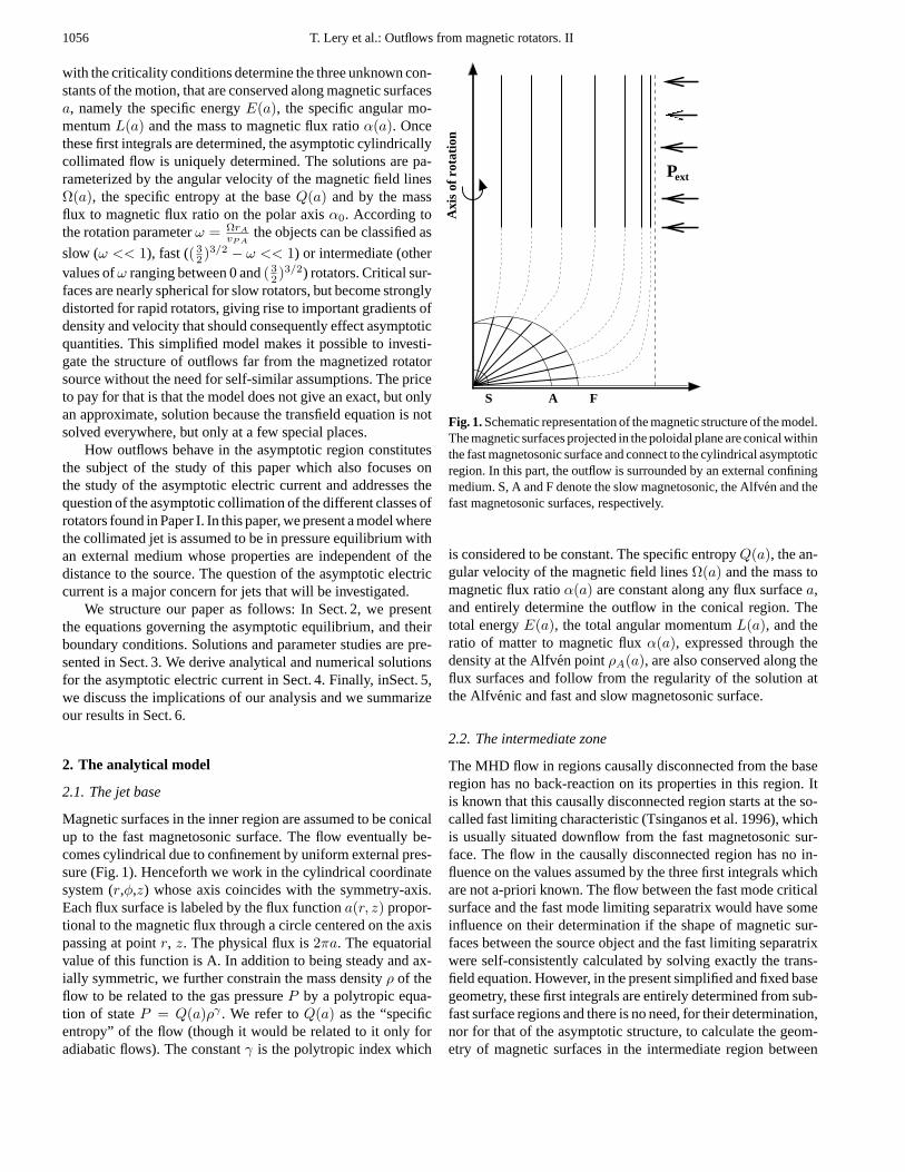
Fig. 1.Schematic representation of the magnetic structure of the model.The magnetic surfaces projected in the poloidal plane are conical withinthe fast magnetosonic surface and connect to the cylindrical asymptoticregion. In this part, the outflow is surrounded by an external confiningmedium. S, A and F denote the slow magnetosonic, the Alfven and thefast magnetosonic surfaces, respectively.
is considered to be constant. The specific entropyQ(a), the an-gular velocity of the magnetic field linesΩ(a) and the mass tomagnetic flux ratioα(a) are constant along any flux surfacea,and entirely determine the outflow in the conical region. Thetotal energyE(a), the total angular momentumL(a), and theratio of matter to magnetic fluxα(a), expressed through thedensity at the Alfven pointρA(a), are also conserved along theflux surfaces and follow from the regularity of the solution atthe Alfvenic and fast and slow magnetosonic surface.
2.2. The intermediate zone
The MHD flow in regions causally disconnected from the baseregion has no back-reaction on its properties in this region. Itis known that this causally disconnected region starts at the so-called fast limiting characteristic (Tsinganos et al. 1996), whichis usually situated downflow from the fast magnetosonic sur-face. The flow in the causally disconnected region has no in-fluence on the values assumed by the three first integrals whichare not a-priori known. The flow between the fast mode criticalsurface and the fast mode limiting separatrix would have someinfluence on their determination if the shape of magnetic sur-faces between the source object and the fast limiting separatrixwere self-consistently calculated by solving exactly the trans-field equation. However, in the present simplified and fixed basegeometry, these first integrals are entirely determined from sub-fast surface regions and there is no need, for their determination,nor for that of the asymptotic structure, to calculate the geom-etry of magnetic surfaces in the intermediate region between

T. Lery et al.: Outflows from magnetic rotators. II 1057
the fast critical surface and the fast mode limiting separatrix.The latter is anyway presumably located not much further awayfrom it and we do not expect large geometrical changes as com-pared to the base region. The lack of complete self-consistencyof our model is therefore mainly contained in our assumptionof base conical geometry. The fact that the shape of surfaces isnot calculated downflow from the fast surface in regions werefield curvature is still present, i.e. where poloidal field lines aredashed in Fig. 1, does not add any supplementary inaccuracy.
The shape of the magnetic surfaces shown in Fig. 1 are simi-lar, to some extent, to shapes obtained by some previous studiesalready performed for a self-consistent calculation of the shapeof the poloidal field lines. Trussoni et al. (1997) have prescribedsimilar types of the magnetic surfaces and then integrated theMHD equations from the base all the way to infinity. Such casecorresponds to meridionally self-similar MHD outflows witha non-constant polytropic indexγ. Sauty & Tsinganos (1994)have also calculated the shape of magnetic field lines by deduc-ing them and integrating the MHD equations from the base tolarge distances.
2.3. The asymptotic structure
The asymptotic structure of the flow is determined by theBernoulli equation and the force balance in the direction perpen-dicular to the field (transfield equation) in terms of the constantsof motionQ,Ω, E, L, α.
The Bernoulli equationLet us defineL as the total angular mo-mentum,ρA as the mass density at the Alfven critical point andG(r, z) as the gravitational potential. The Bernoulli equationcan be given by
12
α2∇a2
ρ2r2 = E(a) − G(r, z) − γ
γ − 1Qργ−1
+ρΩL − r2ΩρA − ρ
− 12
(L
r+
ρ
r
L − r2ΩρA − ρ
)2
. (1)
This equation can be simplified in the asymptotic region, i.e.z going to∞, so that gravity becomes negligible. In the cylin-drical case,∇a is replaced byda/dr. Since we are far fromthe Alfven surface in the asymptotic region, the density of theflow ρ must be smaller than the Alfvenic densityρA. Moreoverwe can considerr to be larger thatrA. Using the assumptionsr rA andρA ρ, the last two terms of the Eq. (1) become
− ρΩ2r2
ρA− 1
2r4AΩ2
r2
[1 − ρr2
ρAr2A
]2. (2)
This is equivalent to
− ρΩ2r2
ρA− ρΩ2r2
ρA
[12
(ρAr2
A
ρr2
)r2A
r2 − r2A
r2 +12
ρ
ρA
]. (3)
The last two terms in brackets are negligible w.r.t. unity. More-over whenz tends to infinity,ρr2 is bounded. Therefore theparenthesis of the first term inside the brackets is also bounded,
and, ifr were to approach infinity, the first term in bracket wouldalso be negligible with respect to unity. We assume that, eventhoughr approaches a finite limit, (rA/r) becomes asymptoti-cally small enough for this first term in bracket to also becomenegligible. Thus the last two terms of the Bernoulli equationcan be approximated at infinity by−ρΩ2r2/ρA. Hence, theBernoulli equation becomes
12
(α
ρr
da
dr
)2
= E − γ
(γ − 1)Qρ(γ−1) − Ω2r2ρ
µ0α2 . (4)
The Transfield equationThe force balance perpendicular to thefield can be written in cylindrical coordinates as
αρr
(∂∂z
αρr
∂a∂z + ∂
∂rαρr
∂a∂r
)− 1
µ0ρr
(∂∂z
1r
∂a∂z + ∂
∂r1r
∂a∂r
)= E′ − Q′ργ−1
γ−1 + α′α
µ0α2ρr2
(L−r2Ω)2
(µ0α2−ρ)2
− ρr2
(L′−r2Ω′)(L−r2Ω)µ0α2−ρ − LL′
r2 . (5)
Primes denote derivatives with respect toa, i.e.E′ = dE/da.Similarly using the same asymptotic assumptions in the trans-field equation, the centrifugal forceρv2
φ/r can be neglected withrespect to “hoop stress”B2
φ/µ0r since
ρv2φ
r=
B2φ
µ0r
(r2A
r2
)(ρAr2
A
ρr2
)(1 − ρr2
ρAr2A
)2
. (6)
Hence due to the simplifications, several force densities vanishin the one-dimensional form of the transfield equation that isthen given by
12
d
da
(α
ρr
da
dr
)2
= E′ − Q′ργ−1
γ − 1+
ρr2Ω2
µ0α2
(α′
α− Ω′
Ω
). (7)
Subtracting the transfield equation (7) from the derivative withrespect toa of the Bernoulli equation (4), one can simplify thetransfield equation that becomes
r2 d
da(Qργ) +
12
d
da
(Ω2r4ρ2
µ0α2
)= 0. (8)
Thus Eqs. (4) and (8) describe the asymptotic equilibrium struc-ture of a magnetized jet with the present assumptions. To studythe equilibrium of this jet taking into account an external ambi-ent pressure, one needs to specify the relevant boundary condi-tion at the jet’s edge.
The Cylindrical collimation It is possible to show that theasymptotic problem with non-vanishing external pressure doesnot accept solutions wherer goes to infinity on any magneticfield line. Indeed, if so,da
dr would vanish at the edge of the jet.As a consequenceBp = 1
rdadr would go to zero at the outer edge
and the toroidal part of the magnetic field would asymptoticallyreduce to
Bφ = µ0αρ
ρA − ρ
L − r2Ωr
≈ −Ωα
ρr2
r. (9)
1058 T. Lery et al.: Outflows from magnetic rotators. II
If ρr2 were to diverge at the edge, the Bernoulli equation (1)would be violated, since the left hand side term is always posi-tive, and the ninth term that is negative and the largest one in ab-solute value could not be balanced by other terms. It would alsobe so if the Alfven radius were to become infinite. This provesthat Bφ andBp should vanish ifr were to approach infinity.If so, the boundary condition reduces toPext = Pgas = Qργ
b .The density at the outer edgeρb would then be finite, andρr2
would diverge which violates the Bernoulli equation as shownabove. This proves thatthe confining pressure limits the jet to afinite radius asz → ∞ and therefore ensure an asymptoticallycylindrical structure.
An upuper limit for the axial densityLet us see now that thephysics of the flow in the inner region close to the source con-strains the maximum value of the asymptotic mass density onthe polar axis,ρ0, and therefore also the total mass flux for agiven magnetic flux. Indeed, on the axis the Bernoulli equationreduces to(v2P/2
)= E − γQργ−1
0 /(γ − 1). (10)
which yields an upper limit to the axial density (the limit corre-sponding to a vanishing asymptotic poloidal velocity),
ρ0 ≤(
γ − 1γ
E
Q
) 1γ−1
. (11)
In the inner region of the flow close to the source the energyhas been calculated (see paper I). For slow rotators (that cor-responds to a rotation parameterω << 1) energy is given byE = A2/2µ2
0α2R4
A, with the Alfven spherical radius equal
to RA =(C1µ0A
2/2)1/(2
√2+4)
, whereC1 is the constant ofintegration of the transfield equation that has been defined an-alytically in Paper I (Eq. (75)) only as a function of the inputparameters. Combining the two last equations with Eq. (11) themaximum density becomes in this case
ρ0,max =
(γ − 1
γ
A2
2µ20α
2Q
(2
C1µ0A2
) 2√2+2
) 1γ−1
. (12)
In the vanishing rotation case, it is then possible to find an an-alytical definition of the maximum density on the axis in theasymptotic region allowed by the input parameters defining theemitting source properties. This also shows that the slow rotatorlimiting density essentially depends on the specific entropyQ.For fast rotators and using Eq. (99) of Paper I that gives energy,the limiting mass density becomes
ρ0,max =(
γ − 1γ
32Q
AΩ2
µ0α
) 1γ−1
. (13)
This limit now depends on the entropy, but also on angularvelocity and mass to magnetic flux ratio. The latter parameter isrelated to mass loss rate on the axis and therefore determine theaxial value of density at the Alfven point. Then an increase ofα0 naturally reduces this limit. Thus, once given the propertiesof the source in our model (Q(a), Ω(a), α0), the asymptoticaxial density possesses an upper limit.
The boundary conditionWe further assume the flow to be inpressure equilibrium with an external medium whose pressureis constant. Equilibrium at the jet boundary is expressed by
Pext = Qργ + (B2P + B2
φ)/(2µ0), (14)
with the magnetic contributions
B2φ
2µ0=
ρ2r2Ω2
2ρA, (15)
B2P
2µ0=
ρ2
ρA
(E − γ
γ − 1Qργ−1 − Ω2r2ρ
ρA
). (16)
It has been used that at the outer boundaryρ << ρA andr >>rA. The pressure of the external medium may have a thermaland a magnetic contribution, too.In the case of a finite externalpressure the jet radius remains finite.
Thus the asymptotic forms of the transfield and the Bernoulliequations and the pressure balance at the jet outer edge consti-tute the set of equations describing the asymptotic structure ofthe pressure-confined jet. The three first integrals of the motionE(a), L(a) andα(a) are obtained from the inner part of theflow (Paper I). At infinity the only free parameter is the externalpressurePext.
3. Numerical analysis
3.1. Numerical procedure
For the numerical calculations, the Bernoulli and the transfieldequations have been reformulated as two ODEs for the radialposition,r, and the density,ρ, as a function of the flux surfacesa. The Bernoulli equation can be written as
dr
da=
α
ρr√
2√
E − γγ−1Qργ−1 − Ω2r2ρ
µ0α2
, (17)
and the transfield equation can be written as(µ0γQργ−2 +
r2Ω2
µ0α2
)1ρ
dρ
da+(
2rΩ2
µ0α2
)dr
da
=r2Ω2
µ0α3
dα
da− µ0ρ
γ−2 dQ
da− r2Ω2
µ0α2
dΩda
. (18)
These two equations can now be written symbolically as
dr
da= fr(r, ρ, E, Q, α, ...), (19)
dρ
da= fρ(r, ρ, E, Q, α, ...), (20)
wherefr is the r.h.s. of Eq. (17) andfρ has a more complex formthat can be easily derived from Eqs. (18) and (17). We use a stan-dard initial condition integrator for stiff systems of first orderODEs. We prescribe the axial density rather than the externalpressure, which is ultimately deduced from the solution. As inpaper I, dimensionless quantitiesΩ, α0 andQ will respectivelybe used forΩ, α0 andQ in order to simplify numerical inves-tigations. The reference units (in CGS) areρref = 70p.cm−3,rref = 1015cm, vref = 107cm.s−1.

T. Lery et al.: Outflows from magnetic rotators. II 1059
0 0.5 1Relative radius
10−8
10−7
10−6
10−5
10−4
10−3
Rel
ativ
e de
nsity
0.005
0.010Βφ
0.5 1Relative radius
0.6
0.8
1
1.2
1.4
VpSlowFast
0.01
0.02Bp
1/r law
Fig. 2. Rotational effects: The azimuthalBφ and poloidalBP magneticfield components (upper left and right panels respectively), densityρand poloidal velocityvP (lower left and right panels) are plotted asfunctions of relative radiusrrel for different values ofΩ (Ω = 2(dashedlines),4, 6, 8, 10, 11(solid lines)). The corresponding values ofω are0.4,1.1,1.3,1.65,1.75 and 1.8. (Q = 2.1 andα0 = 1.7)
We will first consider the case of magnetized winds orig-inating from objects with constant rotation and entropy. Theeffect of the four parameters is studied in the next subsections,followed by a specific application to the TTauri star BP Tau.
3.2. Variations of the rotation
First we study the effect of the dimensionless angular velocity,Ω(a) = Ω∗ of the central object. The other parameters remainconstant. As in paper I, we find that the variations of the an-gular velocity have major effects on solutions as can be seenon Fig. 2 that shows the components of the magnetic field, thedensity and the poloidal velocity for different rotation rates.Ωvaries from2 to 11 (Q∗ = 2.1, α0 = 1.7). For a slow rotator(heavy dashed lines in Fig. 2), the toroidal field increases nearlylinearly, while it possesses a maximum within the jet for fastrotators. We find thatBφ ∝ 1/r while Bp ∝ 1/r2. The two so-lutions respectively corresponds to a diffuse current with nearlyconstant current density, and to a centrally peaked current, sur-rounded by a current-free envelope. A similar behavior has beendiscussed by Appl & Camenzind (1993) for relativistic jets, ac-cording to which the jet configurations had been referred to asdiffuse and sharp pinch. Important variations with respect torotation can also be seen in the other physical quantities. In par-ticular the poloidal velocity is highest in the envelope, thoughvariations remain within a factor of two. In the very fast rotatorlimit the density falls off dramatically in the envelope where thegas pressure becomes negligible compared to the magnetic pres-sure. This is clearly shown in Fig. 3 where the total pressure isrepresented with magnetic and gas pressures.For slow rotators,the gas pressure dominates everywhere in the outflow, while forfast rotators the magnetic pressure dominates in the envelope.
0 0.5 1Relative radius
0
0.001
0.002
0 0.5 10
0.001
0.002
0 0.5 10
0.001
0.002
Total pressureMagnetic pressureGas pressure
0.9 1r
P Pgas mag
P Pgas mag
Slow
Fast
Fig. 3. Rotational effects: Comparison of pressure profiles for slow,fast and very fast rotators. Total, magnetic (Pmag) and gas (Pgas)pressure respectively correspond to solid, dashed and long dashed lines.The rotation parameterω is equal to 0.4, 1.3 and 1.8 top to bottomrespectively.
0 0.5 1Magnetic flux a
10−2
10−1
100
α
Slow rotatorFast rotator
Fig. 4. Rotational effects: Plot of the mass to magnetic flux ratioαwith respect to the relative magnetic fluxa∗ = a
Afor various constant
rotation ratesΩ = 2..11. Solid lines correspond to slow rotators, andlong dashed lines to outflows with largeΩ. All the other parametersand boundary conditions are kept the same.
In the latter case, most of the outer pressure at the outer edge issupported by magnetic field and not by gas pressure.
In Fig. 4, the mass to magnetic flux ratioα is representedas a function of the relative magnetic flux for various angularvelocities. Since the central part of the outflow is denser forfast rotators, the mass flux is very large in this region and veryconcentrated around the axis. It means thatmost of the matteris flowing along the polar axis for fast rotators.
1060 T. Lery et al.: Outflows from magnetic rotators. II
0 0.5 1Relative radius
0.8
0.9
1
1.1
Vp
0 0.5 1Relative radius
0
0.005
0.01
Bp
Small αLarge α
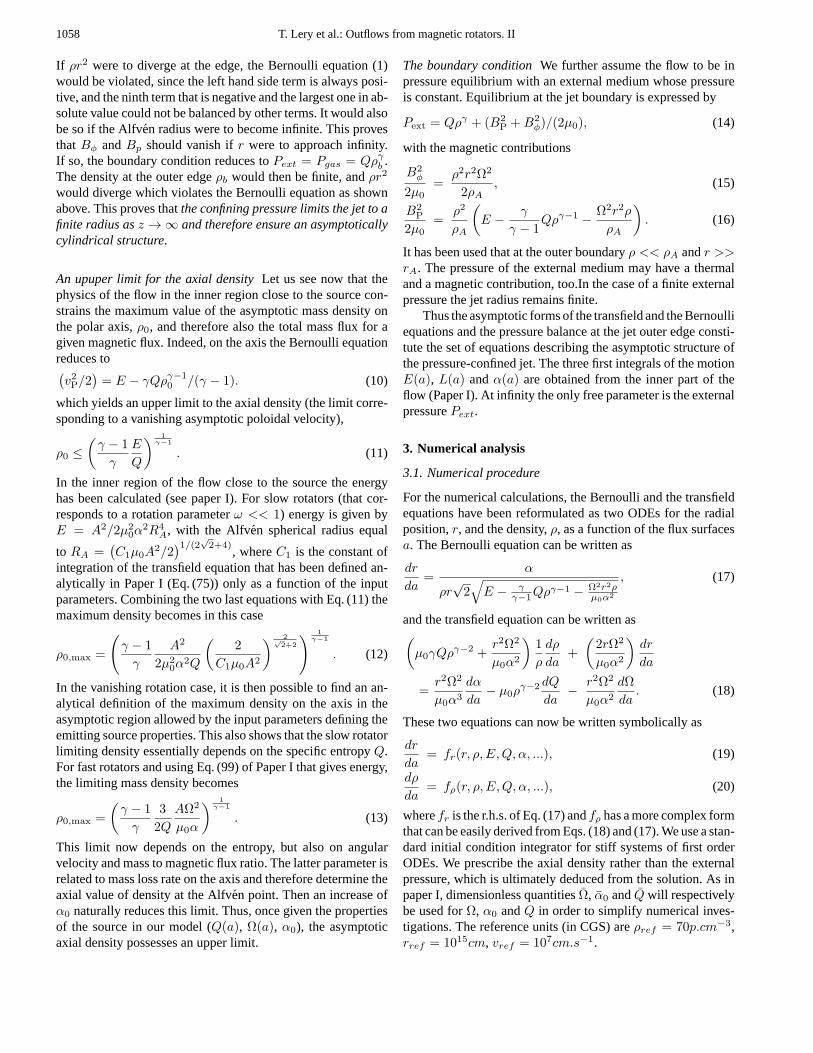
Fig. 5. Mass loss rate effects: Plots of poloidal components of velocityvp (left panel) and magnetic fieldBp (right panel) for various valuesof the mass to magnetic flux ratio on the axisα0. Heavy solid linecorrespond to small mass loss rates and heavy dashed line to largeones. (α0 = 0.7, 0.8, 1, 1.4, 1.8, 2.6, Ω = 5 andQ = 2.5)
3.3. Mass loss rate effects
Another potentially observable quantity is the mass loss rateparticularly interesting since it can be evaluated from observa-tions. The parameter related to the mass loss rate isα0. We havecomputed solutions for differentα0’s, keeping other parametersunchanged. The results are plotted in Fig. 5 where the poloidalcomponents of the velocityvp and the magnetic fieldBp arerepresented as functions of the relative radius. The input valuesareα0 = 0.7, 0.8, 1, 1.4, 1.8, 2.6, Ω = 5 andQ = 2.5. Fromthis figure we can infer thatthe maximum momentum is situ-ated in the axial part, especially for fast rotators. Therefore thecentral part of the jet will propagate more easily in the ambientmedium than the external part.
When the mass loss rate grows, the outflow is slowed downon the edge and accelerated on the axis, while the poloidal mag-netic field is also reduced. Thereforethe jets from the youngeststellar objects, which show the largest mass loss rates, shouldhave a faster central core and a slower envelope than olderones.
The profile of poloidal velocity depends sensitively onα0as well as the core radius that reduces asα0 increases. As foundin Paper I for the inner conical region, it appears that an increasein mass loss rate has a similar effect to a decrease of the rotationrate.
3.4. Thermal effects
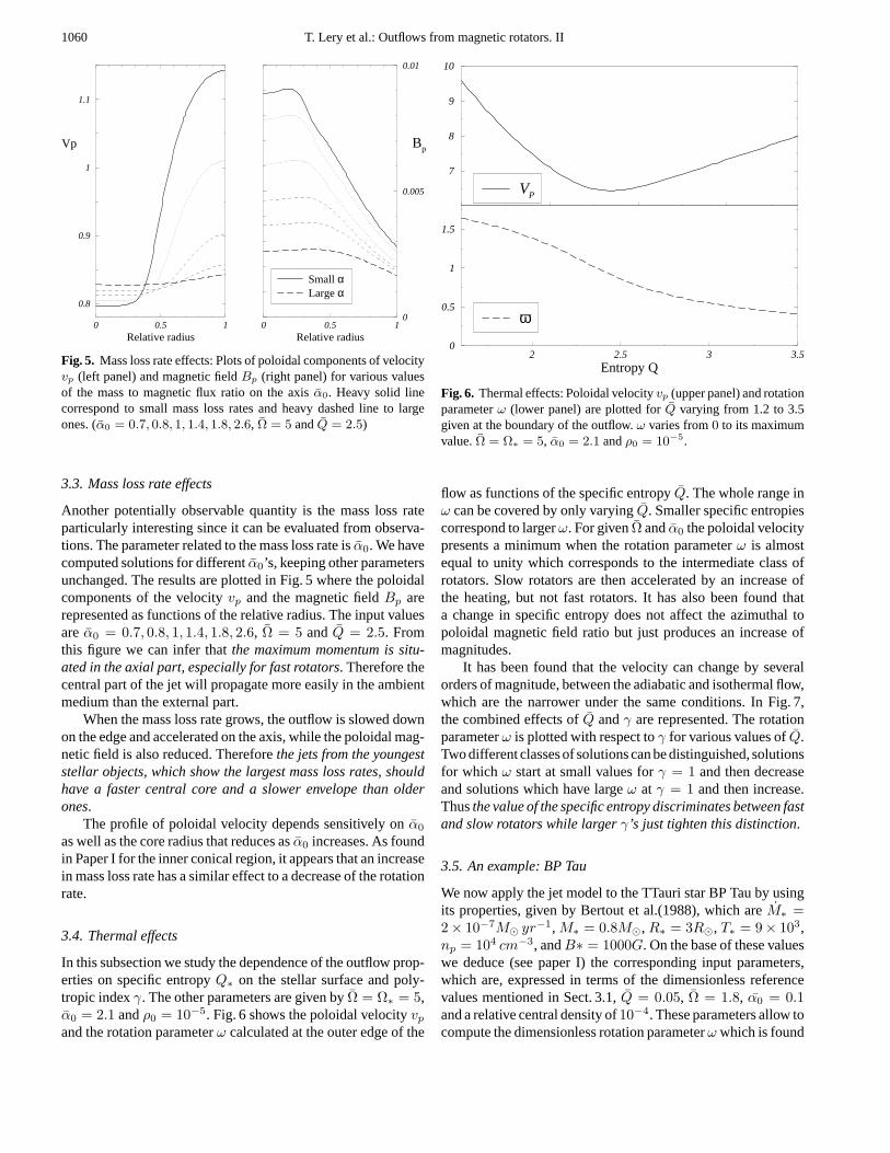
In this subsection we study the dependence of the outflow prop-erties on specific entropyQ∗ on the stellar surface and poly-tropic indexγ. The other parameters are given byΩ = Ω∗ = 5,α0 = 2.1 andρ0 = 10−5. Fig. 6 shows the poloidal velocityvp
and the rotation parameterω calculated at the outer edge of the
2 2.5 3 3.5Entropy Q
0
0.5
1
1.5
ω
7
8
9
10
VP
Fig. 6. Thermal effects: Poloidal velocityvp (upper panel) and rotationparameterω (lower panel) are plotted forQ varying from 1.2 to 3.5given at the boundary of the outflow.ω varies from0 to its maximumvalue.Ω = Ω∗ = 5, α0 = 2.1 andρ0 = 10−5.
flow as functions of the specific entropyQ. The whole range inω can be covered by only varyingQ. Smaller specific entropiescorrespond to largerω. For givenΩ andα0 the poloidal velocitypresents a minimum when the rotation parameterω is almostequal to unity which corresponds to the intermediate class ofrotators. Slow rotators are then accelerated by an increase ofthe heating, but not fast rotators. It has also been found thata change in specific entropy does not affect the azimuthal topoloidal magnetic field ratio but just produces an increase ofmagnitudes.
It has been found that the velocity can change by severalorders of magnitude, between the adiabatic and isothermal flow,which are the narrower under the same conditions. In Fig. 7,the combined effects ofQ andγ are represented. The rotationparameterω is plotted with respect toγ for various values ofQ.Two different classes of solutions can be distinguished, solutionsfor which ω start at small values forγ = 1 and then decreaseand solutions which have largeω at γ = 1 and then increase.Thusthe value of the specific entropy discriminates between fastand slow rotators while largerγ’s just tighten this distinction.
3.5. An example: BP Tau
We now apply the jet model to the TTauri star BP Tau by usingits properties, given by Bertout et al.(1988), which areM∗ =2 × 10⁻⁷M yr−1, M∗ = 0.8M, R∗ = 3R, T∗ = 9 × 10³,np = 104 cm−3, andB∗ = 1000G. On the base of these valueswe deduce (see paper I) the corresponding input parameters,which are, expressed in terms of the dimensionless referencevalues mentioned in Sect. 3.1,Q = 0.05, Ω = 1.8, α0 = 0.1and a relative central density of10−4. These parameters allow tocompute the dimensionless rotation parameterω which is found

T. Lery et al.: Outflows from magnetic rotators. II 1061
1 1.05 1.1 1.15γ
0
0.5
1
1.5
ω
Small QLarge Q
Fig. 7. Thermal effects: The rotation parameterω given at the outerboundary as a function ofγ for different values ofQ (from 1 to 3.5)The smallest values ofQ (represented with solid lines) increase andreach the largest value ofω, while larger value ofQ (dashed lines)decrease and correspond to smaller values ofω.
0 0.5 1Relative radius
0.0
0.5
1.0
Mag
netic
flux
a
10−2
10−1
100
101
BP
Bφ
0.5 1Relative radius
10−3
10−2
10−1
100
ρP
10−2
10−1
100
101
VP
Vφ
Fig. 8. Model for the jet of a TTauri star, BP Tau withΩ = 1.8,α0 = 0.1, Q = 0.05 and a relative central density of10−4 (ω = 1.41).Upper panels correspond to the magnetic field (left) and the velocitycomponents (right). Density and gas pressure (right) together with therelative magnetic flux (left) are represented in the lowest panels as afunction of the relative radiusrrel = r/rjet.
to be 1.41 on the equator, and corresponds to the case of a fastrotator. Magnetic field and velocity components, density andgas pressure in the flow are plotted for BP Tau in Fig. 8 togetherwith the magnetic flux represented as a function of the relativeradius. The reference units (in CGS) areρref = 70p.cm−3,rref = 1015cm, vref = 107 cm.s−1.
The azimuthal component of the magnetic field dominatesthe poloidal part in the envelope. The poloidal velocity does
0 0.5 1Relative radius
0
1e−06
2e−06
Tot
al p
ress
ure
Slow differential rotatorFast differential rotator
Fig. 9. Differential rotators: we plot the total pressure as a function ofthe relative radiusrrel. Slow rotators are represented with solid linesand fast differential rotators with dashed lines. Rotation rate is givenby Ω2.
not show strong variations across the jet, and the azimuthalvelocityvφ is one order of magnitude smaller than the poloidalcomponent.The axial region is the densest and slowest partof the asymptotic flow. This dense core region is a fraction ofthe full jet with a minimum of0.5 for the fastest case. Thiscorresponds to a central core of the order of5 × 1014cm. Evenif the fastest part is the outer one the maximum momentum islocated around the polar axis. Hence even if the relative velocityis smaller close to the axis the central region of the flow willpropagate faster in the ambient medium. It also is found that,only in the central part of the asymptotic outflow, does the kineticenergy flux dominate over Poynting flux. Thusa large part of themagnetic energy has not been transferred to the kinetic energyin the case of constant rotation.
3.6. Non-constantΩ andQ
The profiles of the differential angular velocities, that we use(See Paper I), are defined as follows:Ω0 corresponds to a con-stant rotation rate across the flow,Ω1 is a profile varying fromΩ0 to zero with a step-like transition, the same forΩ3 but moresmoothly,Ω2 andΩ5 vary fromΩ0 to Ω0/2 and1.5 × Ω0 re-spectively and finallyΩ4 follows the differential rotation of aSolar-type star. The profiles of specific entropies are as follows:Q0 is constant across the flow,Q1 varies fromQ0 to Q0/2 andQ2 varies fromQ0 to zero likeQ1 but more smoothly in thelatter case.
A number of well-collimated outflows are observed to havelarger poloidal velocities near the polar axis, and lower veloci-ties at the edge of the flow. This motivated us to use a profile oftypeΩ2 that could reproduce such behaviors. Fig. 9 representsthe total pressure for such differential rotators with respect to therelative radius for a set of central values of the angular velocity.Similarly to rigid rotators, the pressure globally decreases from
1062 T. Lery et al.: Outflows from magnetic rotators. II
0 0.5 1Relative radius
0
0.002
0.004
0.006
0.008
0.01P
ress
ure
PGas
Pmag
Ptot
0.5 1Relative radius
Constant Q Differential Q
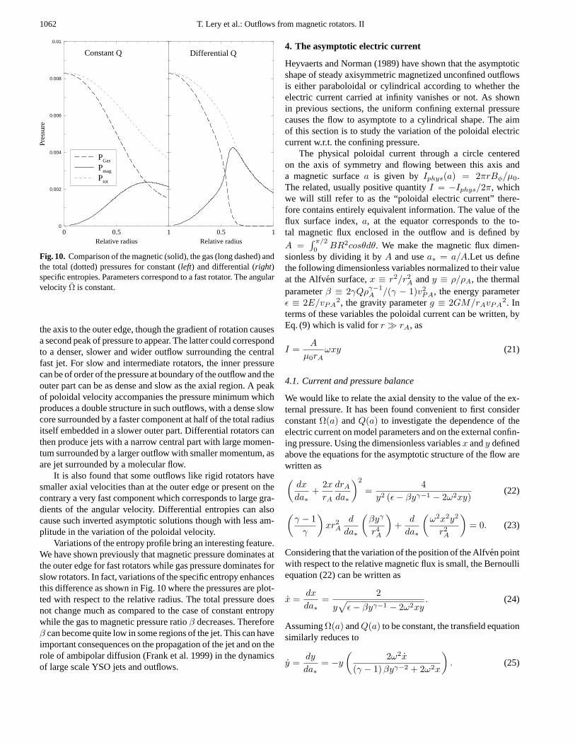
Fig. 10. Comparison of the magnetic (solid), the gas (long dashed) andthe total (dotted) pressures for constant (left) and differential (right)specific entropies. Parameters correspond to a fast rotator. The angularvelocity Ω is constant.
the axis to the outer edge, though the gradient of rotation causesa second peak of pressure to appear. The latter could correspondto a denser, slower and wider outflow surrounding the centralfast jet. For slow and intermediate rotators, the inner pressurecan be of order of the pressure at boundary of the outflow and theouter part can be as dense and slow as the axial region. A peakof poloidal velocity accompanies the pressure minimum whichproduces a double structure in such outflows, with a dense slowcore surrounded by a faster component at half of the total radiusitself embedded in a slower outer part. Differential rotators canthen produce jets with a narrow central part with large momen-tum surrounded by a larger outflow with smaller momentum, asare jet surrounded by a molecular flow.
It is also found that some outflows like rigid rotators havesmaller axial velocities than at the outer edge or present on thecontrary a very fast component which corresponds to large gra-dients of the angular velocity. Differential entropies can alsocause such inverted asymptotic solutions though with less am-plitude in the variation of the poloidal velocity.
Variations of the entropy profile bring an interesting feature.We have shown previously that magnetic pressure dominates atthe outer edge for fast rotators while gas pressure dominates forslow rotators. In fact, variations of the specific entropy enhancesthis difference as shown in Fig. 10 where the pressures are plot-ted with respect to the relative radius. The total pressure doesnot change much as compared to the case of constant entropywhile the gas to magnetic pressure ratioβ decreases. Thereforeβ can become quite low in some regions of the jet. This can haveimportant consequences on the propagation of the jet and on therole of ambipolar diffusion (Frank et al. 1999) in the dynamicsof large scale YSO jets and outflows.
4. The asymptotic electric current
Heyvaerts and Norman (1989) have shown that the asymptoticshape of steady axisymmetric magnetized unconfined outflowsis either paraboloidal or cylindrical according to whether theelectric current carried at infinity vanishes or not. As shownin previous sections, the uniform confining external pressurecauses the flow to asymptote to a cylindrical shape. The aimof this section is to study the variation of the poloidal electriccurrent w.r.t. the confining pressure.
The physical poloidal current through a circle centeredon the axis of symmetry and flowing between this axis anda magnetic surfacea is given by Iphys(a) = 2πrBφ/µ0.The related, usually positive quantityI = −Iphys/2π, whichwe will still refer to as the “poloidal electric current” there-fore contains entirely equivalent information. The value of theflux surface index,a, at the equator corresponds to the to-tal magnetic flux enclosed in the outflow and is defined by
A =∫ π/20 BR2cosθdθ. We make the magnetic flux dimen-
sionless by dividing it byA and usea∗ = a/A.Let us definethe following dimensionless variables normalized to their valueat the Alfven surface,x ≡ r2/r2
A andy ≡ ρ/ρA, the thermalparameterβ ≡ 2γQργ−1
A /(γ − 1)v2PA, the energy parameter
ε ≡ 2E/vPA2, the gravity parameterg ≡ 2GM/rAvPA
2. Interms of these variables the poloidal current can be written, byEq. (9) which is valid forr rA, as
I =A
µ0rAωxy (21)
4.1. Current and pressure balance
We would like to relate the axial density to the value of the ex-ternal pressure. It has been found convenient to first considerconstantΩ(a) andQ(a) to investigate the dependence of theelectric current on model parameters and on the external confin-ing pressure. Using the dimensionless variablesx andy definedabove the equations for the asymptotic structure of the flow arewritten as(
dx
da∗+
2x
rA
drA
da∗
)2
=4
y2 (ε − βyγ−1 − 2ω2xy)(22)
(γ − 1
γ
)xr2
A
d
da∗
(βyγ
r4A
)+
d
da∗
(ω2x2y2
r2A
)= 0. (23)
Considering that the variation of the position of the Alfven pointwith respect to the relative magnetic flux is small, the Bernoulliequation (22) can be written as
x =dx
da∗=
2
y√
ε − βyγ−1 − 2ω2xy. (24)
AssumingΩ(a) andQ(a) to be constant, the transfield equationsimilarly reduces to
y =dy
da∗= −y
(2ω2x
(γ − 1)βyγ−2 + 2ω2x
). (25)
T. Lery et al.: Outflows from magnetic rotators. II 1063
This equation integrates as
βyγ−1 + 2ω2xy = C (26)
where C is an integration constant which can be related to theaxial densityy(x = 0) = y0 as
C = βyγ−10 (27)
Using Eq. (26), Eq. (21) becomes
I =A
2rAµ0
β
ω
(yγ−10 − yγ−1
b
)(28)
whereyb is the density at the outer edge. The condition for a van-ishing asymptotic current is simplyy0 = yb. In order to relatethe latter density to the external pressure, the transfield equation(25) can be reformulated in differential form and, making useof the definition of its integration constantC in Eq. (26), can becast in the equivalent form
y = − 2ω2y2x
(γ − 2)βyγ−1 + C(29)
and the Bernoulli equation is simply
x = 2/y√
ε − C (30)
Substitutingx from Eq. (30) in Eq. (29) we obtain
y((γ − 2)βyγ−2 + C/y
)= −4ω2/A
√ε − C (31)
that can be integrated between the axis and the outer edge of theoutflow (y varies fromy0 to yb anda varies from 0 to 1)
C ln(
yb
y0
)+
β(γ − 2)γ − 1
(yγ−1
b − yγ−10
)= − 4ω2
√ε − C
. (32)
Note that for this integration the energy has been considered asalmost constant w.r.t.a, i.e. it does not vary significantly acrossthe jet. This approximation is justified numerically. Pressurebalance at the outer edge of the jet gives a relation between theexternal pressure and the axial density
Pext =γ − 1
γβyγ
b + ω2xby2b + y2
b (ε − βyγ−1b − 2ω2xbyb)(33)
wherePext is defined by
Pext ≡ 2µ0r4A
A2 Pext. (34)
Then the pressure balance equilibrium reduces to
Pext =γ − 1
γβyγ
b + ω2xby2b + y2
b (ε − C) (35)
The system of Eqs. (32) and (33) establishes a relation betweenthe external pressurePext and the axial densityy0. Furtherprogress in making it explicit is possible in the case of slowand fast rotators, since simple solutions forε have been foundin paper I.
4.1.1. Slow rotators
Gas pressure is larger than magnetic pressure at the outer bound-ary for slow rotators. In this caseω 1, and therefore we have
Pext =γ − 1
γβyγ
b ε − C (36)
The energy parameterε has been calculated for slow rotators inPaper I and is given byε = 1 + β + 3ω2 − g . Consideringgnegligible with respect toβ as a first approximation, Eq. (36) isgiven by
yb =
(γPext
(γ − 1)β
)1/γ
(37)
Using the definition ofε, Eqs. (27) and (37), the Eq. (32) be-comes
1γ
ln
(γPext
(γ − 1)βyγ0
)+(
γ − 2γ − 1
)(γPext
(γ − 1)βyγ0
) γ−1γ
= − 4ω2
βyγ−10
√1 + ω2 − β(1 + yγ−1
0 )+
γ − 2γ − 1
(38)
The second terms of both the left and right hand sides are neg-ligible with respect to the first terms and this equation can besimplified to
Pext =γ − 1
γβyγ
0 exp− 4ω2γ
βyγ−10
√1 + ω2 − β(1 + yγ−1
0 )(39)
Sinceβ andω have been obtained by a solution for the innerpart of the flow close to the source, this equation is a relationbetween the external pressure and the asymptotic axial density.It is now possible to calculate the poloidal current as a functionof the density on the axis
I ≈ γ − 12µ0rA
βyγ0
ω
(1 − exp
(− 4ω2γ
βyγ−10
))(40)
All other parameters in this formula are given by the solutionin the inner part of the flow close to the source and by theboundary condition on the axis. So Eqs. (39) and (40) allowto give a relation between the external pressure and the totalpoloidal current in the slow rotator case.
4.1.2. Fast rotators
In this case, the gas pressure is negligible with respect to themagnetic pressure at the outer boundary. This means that
Pext = y2b (ε − C) ε − C (41)
Using Eq. (33) and condition (41), Eq. (32) becomes now
C
2ln
(Pext
ε − C
)− C
γ − 1ln(
C
β
)
−β(γ − 2)(γ − 1)
(Pext
ε − C
) γ−12
− γ − 2γ − 1
C = − 4ω2√
ε − C, (42)
1064 T. Lery et al.: Outflows from magnetic rotators. II
which has two simple solutions, when the external pressure be-comes small, which areC ∼ 0 andC ∼ ε ≈ 3ω
43 . In the latter
case the poloidal current is given by
I =A
2rAµ0ω
(3ω4/3 − βyγ−1
b
). (43)
If eitherβ or the relative density at the boundary is small com-pared to unity, it reduces to
I =32
A
rAµ0ω1/3 (44)
It has been shown in paper I that the Alfven radius grow withωfaster thanω1/3 for fast rotators. Then the current decreases asthe rotator gets faster. Fast rotators do not carry the largest elec-
tric current. Whenω approaches its limit( 3
2
) 32 corresponding
to the very fast rotator the current approaches
I =(
32
)3/2A
rAµ0(45)
SincerA has been found in paper I to be proportional toα−1/3,the total current increases withα.
4.2. Variation of the current across the flow
Differentiating the current as given by Eq. (21) with respect toa we find that
dI
da∗=
2Aω
rAµ0√
ε − C
(1 +
4γ
PBφ
Pgas
)−1
(46)
Along the same lines as above, we can study the slow rotatorcase where the gas pressure dominates and the fast rotator casewhich has a strong magnetic pressure at the outer edge. In theformer case, one finds that
dI
da∗∼ 2Aω
rAµ0
√1 + 3ω2 − β − βyγ−1
0
(47)
The slope of the variation of the poloidal current tends to vanishasω decreases. It is proportional toωrA
. For slow rotators thederivative is always positive and then the current is diffuse inthe outflow. For fast rotators,C = βyγ−1
0 ε and one has
dI
da∗∼ Aω1/3γ
2√
3rAµ0
Pgas
PBφ
(48)
The magnitude of the slopedIda∗
tends to vanish for very fastrotators since the gas to magnetic pressure ratio decreases withthe rotation parameter. In the latter case the slope approachessmall values more rapidly than in the slow rotator case. Anotherinteresting point is that the gas to magnetic pressure ratio startsto decrease very rapidly at a small value of the distancer tothe axis, so its derivative goes rapidly to zero across the jet as afunction of radius. This means that all the current must be en-closed in a core around the axis for fast rotators, which shouldcarry concentrated electric current. Thus it has been found an-alytically that slow rotators have a diffuse current while fastrotators carry concentrated electric current around the axis.
0 0.5 1Relative radius
0
0.5
1
2
Cur
rent
I
Slow rotator
0.5 1Relative radius
Fast rotator
on the Alfven surfaceon the Fast surfaceAsymptotically
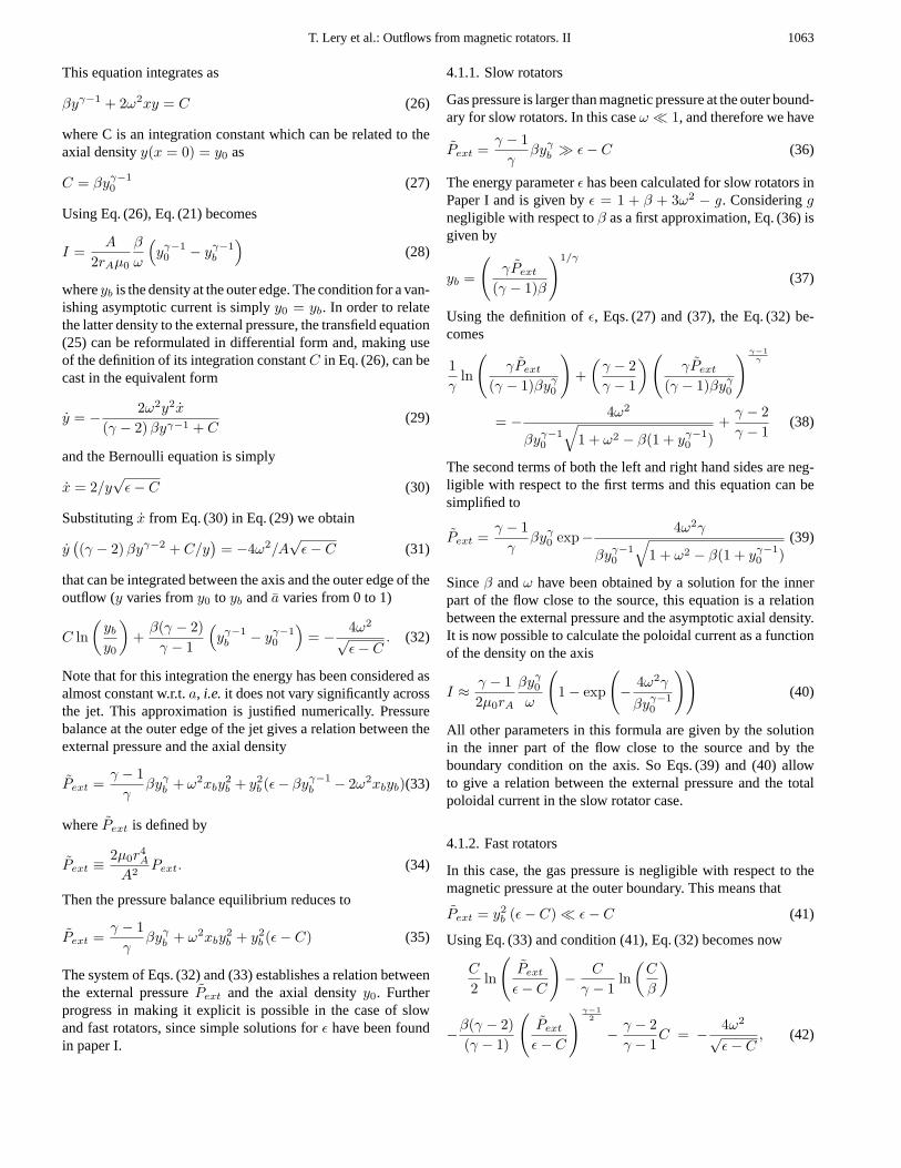
Fig. 11. Variations of the current along the flow for slow (left panel)and fast (right panel) rotators as functions of the relative radius. Theelectric current is calculated in the asymptotic region (solid lines), atthe Alfven surface (dashed lines) and at the fast magnetosonic surface(long dashed lines).
4.3. Evolution of the current along the flow
The variation of the current along one field line gives us fruitfulinformations on the structure of the outflow and on how thevarious quantities evolve from the source to infinity. In Fig. 11,the currents calculated at the Alfven surface, at the fast surfaceand asymptotically are plotted with respect to the relative radius,which is almost linearly related toa∗ = a/A with a slope equalto unity. For slow rotators, the poloidal electric current globallydecreases from the Alfven surface to the asymptotic zone, butis constantly increasing from the polar axis to the edge of thejet. On the other hand the right panel shows that the current atthe Alfven surface has a peak close to the polar axis for fastrotators. The current then decreases at larger distances fromthe axis which reveals the existence of a return electric currentflowing around the central electric flow. This illustrates thatthesolutions obtained with this model carry return currents at otherlocations than at the polar axis, contrary to self-similar models.
4.4. Influence of source properties
The parameters whose changes produce the strongest variationsof the solutions are the angular velocityΩ and the mass to mag-netic flux ratio on the axisα0. The left panel of Fig. 12 representsthe variations of the asymptotic poloidal current with the rel-ative radius for various values ofΩ. As the rotation increases,the current first increases but soon starts to decrease. Moreoverthe maximum current does not correspond to the largest rota-tion rate. On the right panel of Fig. 12, the current is plottedfor different values ofα0 for a givenΩ. The larger the massto magnetic flux ratio, the more the properties of the outflow

T. Lery et al.: Outflows from magnetic rotators. II 1065
0 0.5 1Relative radius
0
0.5
1
Cur
rent
I
Slow rotatorFast rotator
0 0.5 1Relative radius
0
0.25
0.5
Cur
rent
I
Small α0Large α0
Fig. 12. Plots of the asymptotic electric current profile for differentvalues of constant angular velocityΩ (left panel) and of the mass tomagnetic flux ratio on the axisα0 (right panel). Heavy solid linescorrespond to slow rotators (left panel) and to smallα0 (right panel),while fast rotators (left panel) and largeα0 are plotted with heavy longdashed lines. Thin dashed lines correspond to intermediate values.
resemble those of a slow rotator. The current profile changesfrom a concentrated one, signature of a fast rotator, to a morediffuse one for the largestα0. The total current increases at themeantime. Sojets with large mass loss rate also possess a largecurrent.
4.5. Influence of the external pressure
We plot in Fig. 13 the total asymptotic poloidal current in the jetas a function of the confining pressure for different types of ro-tators ranging from slow to very fast ones. All other parametersare kept constant. The external pressure can be reduced untilthe jet reaches unphysical size. The total current diminishes asthe external pressure drops for all types of rotators but never ap-proaches a constant non-vanishing limit for the smallest valuesof the pressure. The slowest rotator in Fig. 13 shows an effectof pressure threshold. For pressures larger than some thresholdvalue the current is almost constant but it strongly decreases forsmaller ones. For very fast rotators the current varies little withexternal pressure.
It would have been interesting to reach a conclusion onwhether the asymptotic poloidal current vanishes or not in thelimit of vanishing confining pressures. This issue is impor-tant because it distinguishes the different possible asymptoticregimes for unconfined jets (Heyvaerts and Norman, 1989).Fig. 13 does not show any leveling-off of the currentI aslogPext
approaches−∞. Regardless of the smallness of the limitingvalues of the pressure that have been reached, this study doesnot allow to conclude that the current vanishes when the pres-sure rigorously does. However, from a practical point of view,it appears that a significant residual current remains, even forexceedingly small, but non-vanishing, confining pressure.
−150 −100 −50 0log(Pext)
−4
−3
−2
−1
0
log(
I)
Slow rotatorIntermediate rotatorFast rotator
Fig. 13. Variations of the asymptotic electric current with the externalconfining pressure for various types of rigid rotators. The solid linescorrespond to the fastest rotators while the dashed lines stand for slowrotators.Q = 3.1, α0 = 2.5 andΩ varies from 0.1 to 15 correspondingto ω varying from 0.1 to 1.8.
4.6. Differential rotators
We now investigate solutions with large gradients of the angularvelocity, i.e.ω x. Eq. (25) can be written as
(γ − 1)βyγ−1y + 2ω2xy2 (y/y + ω/ω) = 0 (49)
In this case the transfield equation can be integrated neglectingthe relative derivative of the radius with respect to the relativederivatives of the density and of the rotation parameter. Theintegral is
γ − 1γ
βyγ + ω2xy2 = βyγ−10 (50)
Eq. (50) can be transformed using Eq. (21) into an equation forthe current, that we will noteIdiff , the solution of which is
Idiff =A
rAµ0
γ − 1γ
β
ωyb
(yγ−10 − yγ−1
b
)(51)
This is different from the solution for the rigid rotator case, thatcan be notedIrig. The relation between them is
Idiff =(
γ − 1γ
)2yb
Irig (52)
This shows that the total current for differential rotators withlarge gradients of angular velocity will be larger since the den-sity on the boundary is small compared to unity. This can clearlybe seen in the left panel of Fig. 14 where the current is plottedwith respect to the radius for different types of differential ro-tators. The largest values of the current correspond to profileswhere the gradients of the angular velocity are positive and arethe largest, namely for profiles of typeΩ2, where the angular ve-locity takes half of its value at the middle of the outflow. Fig. 14

1066 T. Lery et al.: Outflows from magnetic rotators. II
0 0.5 1Relative radius
0
1
2C
urre
nt I
Ω0
Ω2
Ω4
Ω5
0 0.5 1Relative radius
0
0.5
1
Cur
rent
I
Q0
Q1
Q2
Q3
Fig. 14. Plots of the electric current profiles across the flow with respectto the relative radiusrrel = r
rjet. Left panel stands for differential
angular velocities and right panel shows differential specific entropies.Note the difference of ranges between different panels.
shows that the profile of the angular velocity is of prime impor-tance, and that variations of the entropy with flux have a lesserinfluence on the current profile. Thusjets from differential ro-tators will carry a larger current and might be more collimatedthan rigidly rotating outflows.
5. Comparison between numerical resultsand a simplified model
In a review of the theory of magnetically accelerated outflowsand jets from accretion disks, Spruit (1994) discusses the asymp-totic wind structure. As in paper I, using his simplifications andmethod, we find that
xy = 1 −(
α
α∗ω
)4/3(rA
r∗
)2
. (53)
The net current from this simplified analytical model, that wewill note Isimp, is defined by Eq. (21). It is given in the presentcase by
Isimp =9ωA
5µ0r∗
(α
α∗
)1/3(
1 −(
5α
9α∗ω2
)2/3)
(54)
Thusthe current is proportional to the angular velocity and themass loss rate with the following dependencies
Isimp ∝ ΩM1/3 (55)
The current can also be given as a function of the rotation pa-rameterω and of the Alfven radius by
Isimp ≈ 3ω1/3A/2µ0rA (56)
We have plotted this analytical solution with respect toω inFig. 15 together with the corresponding numerical solution. Asω increases and passes0.5, the two solutions separate in the
0 0.5 1 1.5ω
0
0.5
1
Cur
rent
I
Numerical currentAnalytical current
Fig. 15. Comparison of numerical results (solid line) and analyticalsolutions (dashed line) of the asymptotic electric currentI with respectto the rotation parameterω.
intermediate rotator region to converge again in the limit ofvery fast rotators. As shown previously the current increaseswith respect toω for slow rotators and diminishes in the otherlimit. So the analytical results we have found for the current arein qualitative agreement with the real value.
The Poynting fluxIt is also interesting to calculate the Poynt-ing flux per unit escaping mass which can be written asS =ΩrBφ/µ0α = IΩ/α. Using our dimensionless variables it canbe expressed as
S =A2
µ0ρAr4A
ω2xy =A
ρAr3A
Iω (57)
Using the previous Eq. (54), the Poynting flux for the abovesimplified analytical model is given by
Ssimp =A
ρAr3A
9ω2A
5µ0r∗
(α
α∗
)1/3(
1 −(
5α
9α∗ω2
)2/3)
. (58)
Thusthe Poynting flux scales with the rotation and the mass lossrate as
Ssimp ∝ Ω2 M−2/3. (59)
This analytical solution is plotted with respect to the rela-tive radius together with the numerical results with the sameinput parameters. The agreement is good all across the out-flow, and Eq. (58) well reproduces the behavior of the asymp-totic Poynting flux. Eq. (58) can be combined with the con-straint on the boundary mass densityρb given in paper I by[S2H
]slow
≥ [S2H
]fast
where the specific enthalpyH isgiven at the slow and fast surfaces Thus the asymptotic densityat the outer edge of the outflow has an upper bound in termsof quantities defined in the inner part of the outflow close to itssource. The wind carries both kinetic and magnetic energy, the
T. Lery et al.: Outflows from magnetic rotators. II 1067
0 0.5 1Relative radius
0
5
10
15
20P
oynt
ing
Flu
x
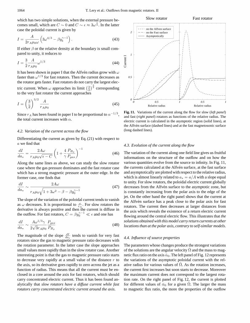
Numerical STheoretical S
Fig. 16. Comparison of numerical results (solid line) and analyticalsolutions (dashed line) for the Poynting fluxS across the outflow asfunctions of the relative radiusrrel = r
rjet.
asymptotic ratio of these, at large distance, is a measure of theimportance of the magnetic component. The kinetic energy fluxisK = ρv2
p/2. The Poynting to kinetic energy flux ratio is givenby q = S/K = 3ω4/3v2
pA/ρv2p The effects of the external pres-
sure on the Poynting to kinetic energy fluxes ratioq have beencalculated for the different classes of rotators. It is found that thefaster the rotator, the larger the ratioq which increases with theconfining pressure. Moreoverin the asymptotic regime, most ofthe magnetic energy has been transformed into kinetic energyin the central core close to the axis, contrary to the envelopewhereq can be very large.
6. Conclusions
We have considered the asymptotic behavior of outflows of mag-netized rotators confined by an external uniform pressure in theframework of our simplified model. The asymptotic forms ofthe transfield and the Bernoulli equations were used to deter-mine the jet structure taking into account the pressure balanceacross the interface between the flow and the external confiningmedium. No self-similar assumption has been made. The givenconfining pressure has been regarded as a boundary conditionand the constants of the motion obtained in the inner part of theflow close to the emitting source have been used. The full rangeof possible variations of the parameters has been explored.
Slow rotators are dominated by thermal effects from theaxis to the outer edge. The specific entropy however has littleinfluence on their asymptotic magnetic field. In the case of fastrotators rotational and mass loss rate effects have the most im-portant influences on solutions. Magnetic pressure dominatesat the outer edge of the flow. Such rotators asymptotically havea concentrated azimuthal magnetic fieldBφ, small mass lossrates and large density gradients. A large part of the magnetic
energy is not transferred to the kinetic energy and the outflowis asymptotically strongly magnetized and carries a significantPoynting flux.
Whatever the type of rotator, isothermal jets are narrowerthan adiabatic ones under the same conditions. The densest jetsare slower on the boundary than lighter ones. In the case ofslow rotators, an analytical solution for the current in terms ofthe axial density, thermal and rotation parameters has been ob-tained. This relation combined with the analytical solution givesthe asymptotic current as a function of the confining pressure.An analytical solution for the poloidal current has also beenobtained in the case of the fast rotator in terms of the rotationparameter and the Alfven radius. The current in slow rotatorsis diffuse in the outflow while fast rotators carry a concentratedelectric current around the axis. The solutions obtained with ourmodel can carry return currents out of the polar axis, contrary toself-similar models. The comparison between numerical resultsand approximate analytic solutions show the latter to be goodqualitative estimators of the real value.
Non constant profiles of rotation and, to a lesser extent ofentropy, cause the solutions to change drastically. For example,the largest asymptotic poloidal velocity can be located either onthe axis or at the outer edge according to the profile ofΩ(a). Ithas been possible to find solutions resembling observed flowssuch as central jets with important momentum surrounded by alarger outflow. Large currents can be generated by differentialrotators if the gradient of the angular velocity is large and theangular velocity does not vanish on the outer edge of the flow.
Thus our model makes it possible to relate the propertiesof the asymptotic part of an outflow to those of the source.These asymptotic equilibria can be used as input solutions fornumerical simulations in order to investigate the propagation ofjets and the instabilities that can develop in magnetized outflows.
Acknowledgements.We would like to thank Kanaris Tsinganos for hisremarks as referee that helped to clarify some of the derivations anddiscussions of equations.
References
Appl S., Camenzind C., 1993, A&A 274, 699Bertout C., Basri G., Bouvier J., et al., 1988, ApJ 330, 350Blandford R.D., Payne D.G., 1982, MNRAS 199, 883Chan K.L., Henriksen R.N., 1980, ApJ 241, 534Contopoulos J., Lovelace R.V.E., 1994, ApJ 429, 139Ferreira J., Pelletier G., 1993, A&A 276, 625Ferreira J., Pelletier G., 1993b, A&A 276, 637Ferreira J., 1997, A&A 319, 340Fiege J.D., Henriksen R.N., 1996, MNRAS 281, 1038Frank A., Mellema G., 1996, ApJ 472, 684Frank A., Gardiner T., Delemarter G., Lery T., Betti R., 1999, ApJ, in
pressHenriksen R.N., Valls-Gabaud D., 1994, MNRAS 266, 681Heyvaerts J., Norman C., 1989, ApJ 347, 1055Heyvaerts J., 1996, In: Chiuderi C., Einaudi G. (eds.) Plasma Astro-
physics. Springer, 31Lery T., Heyvaerts J., Appl S., Norman C.A., 1998, A&A 337, 603Lery T., Henriksen R.N., Fiege J.D., 1999, A&A, in press

1068 T. Lery et al.: Outflows from magnetic rotators. II
Li Z.Y., Chiueh T., Begelman M.C., 1992, ApJ 394, 459MacGregor K.B., 1996, In: Tsinganos K. (ed.) Solar and Astrophysical
MHD flows. Kluwer Academic Publishers, 301Ostriker E.C., 1997, ApJ 486, 291Ouyed R., Pudritz R., 1997, ApJ 482, 712Pelletier, G., Pudritz R.E., 1992, ApJ 394, 117Sauty C., Tsinganos K., 1994, A&A 287, 893Shu F.H., Lizano S., Ruden S.P., Najita J., 1988, ApJ 328, L19Shu F.H., Najita J., Ostriker E., et al., 1994, ApJ 429, 781Shu F.H., Najita J., Ostriker E., Shang H., 1997, ApJ 455, L155
Spruit H.C., 1994, In: Lynden-Bell D. (ed.) Cosmical Magnetism.NATO ASI Series C. Kluwer, 422, 33
Trussoni E., Tsinganos K., Sauty C., 1997, A&A 325, 1099Tsinganos K., Sauty C., 1992, A&A 255, 405Tsinganos K., Trussoni E., 1991, A&A 249, 156Tsinganos K., Sauty C., Surlantzis G., Trussoni E., Contopoulos J.,
1996, In: Tsinganos K. (ed.) Solar and Astrophysical MHD Flows.Kluwer Academic Publishers, 379
Weber E.J., Davis L., 1967, ApJ 148, 217


![ECGsignaldenoisingandbaselinewandercorrectionbasedontheemp ...€¦ · gular value decomposition [13], and independent component analysis [14]. In this paper, we propose a new method](https://img.pdfslide.us/doc/110x75/60a11dd71c93fd17095fab27/ecgsignaldenoisingandbaselinewandercorrectionbasedontheemp-gular-value-decomposition.jpg)