Embed Size (px)
Citation preview
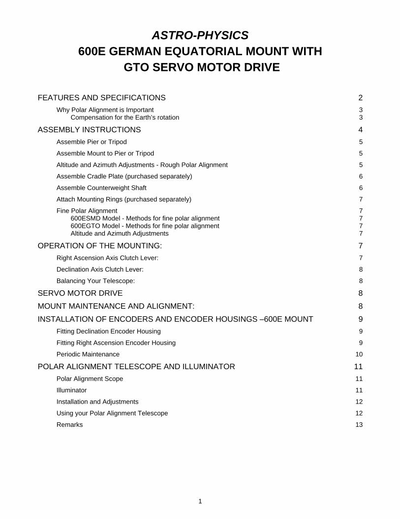
ASTRO-PHYSICS 600E GERMAN EQUATORIAL MOUNT WITH
GTO SERVO MOTOR DRIVE FEATURES AND SPECIFICATIONS 2
Why Polar Alignment is Important 3 Compensation for the Earth’s rotation 3
ASSEMBLY INSTRUCTIONS 4 Assemble Pier or Tripod 5
Assemble Mount to Pier or Tripod 5
Altitude and Azimuth Adjustments - Rough Polar Alignment 5
Assemble Cradle Plate (purchased separately) 6
Assemble Counterweight Shaft 6
Attach Mounting Rings (purchased separately) 7
Fine Polar Alignment 7 600ESMD Model - Methods for fine polar alignment 7 600EGTO Model - Methods for fine polar alignment 7 Altitude and Azimuth Adjustments 7
OPERATION OF THE MOUNTING: 7 Right Ascension Axis Clutch Lever: 7
Declination Axis Clutch Lever: 8
Balancing Your Telescope: 8
SERVO MOTOR DRIVE 8 MOUNT MAINTENANCE AND ALIGNMENT: 8 INSTALLATION OF ENCODERS AND ENCODER HOUSINGS –600E MOUNT 9
Fitting Declination Encoder Housing 9
Fitting Right Ascension Encoder Housing 9
Periodic Maintenance 10
POLAR ALIGNMENT TELESCOPE AND ILLUMINATOR 11 Polar Alignment Scope 11
Illuminator 11
Installation and Adjustments 12
Using your Polar Alignment Telescope 12
Remarks 13
1

ASTRO-PHYSICS
600E GERMAN EQUATORIAL MOUNT WITH GTO SERVO MOTOR DRIVE
MODEL 600E PARTS LIST 1 600E Equatorial Head with servo drive 1 GTO Servo Drive Electronics Box and Carrying Case 1 GTO Keypad Controller with 15’ Coiled Cable 1 Stainless counterweight shaft with washer stop and black plastic knob (5/16-18 threaded rod) 1 D.C. power cord (cigarette lighter adapter) – 8” long 1 DigitalSky Voice ™ Software (CD-ROM) 3 Black plastic knobs with 1/4-20 threaded rod 1 5 and 10mm hex keys 2 Red Caplugs In order to fully assemble and use your mount, you will need the following items sold separately: mounting plate, pier or tripod, portable rechargeable battery pack and counterweights. Several sizes and types are available for your selection. Many of these items will be discussed throughout these instructions.
Several additional options are available: Santa Barbara Instrument Group CCD Imaging cameras and ST-4 Autoguider - if you plan to pursue CCD imaging or
astrophotography
Polar axis telescope - threads into the base of the polar axis assembly. This item is not really needed since both the keypad controller and DigitalSky Voice™ software will guide you through polar alignment procedures.
Mounted encoders - you will need these if you plan to use digital setting circles. Keep in mind that these 4000 step encoders which read the position of the shaft are very coarse (324 arc seconds) while the encoders that are built into the servo motor itself is 0.05 arc seconds.
JMI Digital setting circles - The go-to keypad will perform most of the functions of the digital setting circles. One advantage of the JMI unit is the ability to move the telescope by hand while the unit displays your position.
FEATURES AND SPECIFICATIONS RA/Dec worm wheel: 4” fine pitched bronze wheel Worm gear: Stainless steel Counterweight shaft: 1.125” diameter stainless
steel, removable RA/Dec shafts: 2.5” hollow shafts Latitude range: 15 to 57 degrees Azimuth adjustment: Approximately 17 degrees Setting circles: Porter Slip Ring design, engraved Right ascension: 10-minute increments,
2-minute vernier Declination: 1-degree increments, pointer Motors: Zero-cogging servo motors Power Consumption: 0.4 amps at the sidereal rate 2 amps both motors slewing Power requirements: 12 VDC Weight of mount: 27 lbs. (12.3 kg)
2

INTRODUCTION The 600E German equatorial mount offers many fine features to provide superb performance in a compact, portable package. Rigid aluminum castings enclose the worm gears and the right ascension and declination motors. Drive components are protected from dirt and dust, extraneous wires and gearing are eliminated, and the overall appearance is enhanced. It was engineered to provide a firm, steady platform for your high-resolution instrument.
The DC servo motor drive with GTO computer system, including the keypad controller with its digital display screen and DigitalSky Voice software offer extraordinary sophistication for today’s observer. Whether you enjoy visual astronomy exclusively or plan an aggressive astrophotography or CCD imaging program, this mount will allow you to maximize your night out under the stars.
The advanced keypad features allow you to slew automatically to objects in a wide range of databases as well as any RA/Dec coordinate. A large selection of common names for stars and other objects makes your selection a snap. The rapid slew rate of 5 degrees per second (1200x) allows you to locate objects very quickly and accurately. You will be very pleased with the intuitive operation of this controller. There are no complicated sequences of keystrokes to remember. It is so easy to use that even it you don’t use it for a few months, you will feel at home with the keypad very quickly.
DigitalSky Voice software provides additional capabilities to control the movement of your telescope by using two-way verbal communication with a microphone or by a few clicks of your computer mouse (or touchpad). You can remain at the eyepiece while you direct your telescope with verbal commands. There is no need to put a flashlight in your mouth to see the keyboard. You have total control with your voice and/or mouse. Voice control also allows you to retain your dark adaption.
In order to maximize your pleasure on your first night out, we recommend that you familiarize yourself with the assembly and basic operation of the mount indoors. The temperature will be comfortable, the mosquitoes at bay, and you'll have enough light to see the illustrations and read the manual. Please take particular note of counterbalancing, use of the clutches and operation of the keypad controller.
Why Polar Alignment is Important
Compensation for the Earth’s rotation If you were to take a long exposure photograph with Polaris (often called the North Star) in the center of the field, you would discover that all stars seem to revolve around Polaris. This effect is due to the rotation of the earth on its axis. Motor driven equatorial mounts were designed to compensate for the earth's rotation by moving the telescope at the same rate and opposite to the earth's rotation. When the polar axis of the telescope is pointed at the celestial pole (polar aligned) as shown in Diagram 1, the mount will follow (track) the motions of the sun, moon, planets and stars. As a result, the object that you are observing will appear motionless as you observe through the eyepiece or take astrophotos.
Diagram 1
3

ASSEMBLY INSTRUCTIONS Please read all instructions before attempting to set up your 600E mount. The Model 600E is very rugged, however like any precision instrument, it can be damaged by improper use and handling. Please refer to Diagram 2 for illustrations of the mount. The parts are labeled so that we can establish common terminology.
The following terms and abbreviations are used interchangeably in these instructions:
Polar axis=right ascension axis = R.A. axis = R.A. housing
Declination axis = dec. axis = dec. housing
Diagram 2
4
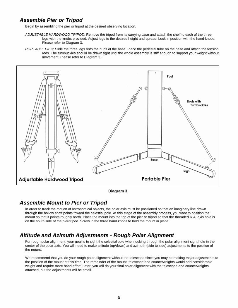
Assemble Pier or Tripod Begin by assembling the pier or tripod at the desired observing location.
ADJUSTABLE HARDWOOD TRIPOD: Remove the tripod from its carrying case and attach the shelf to each of the three legs with the knobs provided. Adjust legs to the desired height and spread. Lock in position with the hand knobs. Please refer to Diagram 3.
PORTABLE PIER: Slide the three legs onto the nubs of the base. Place the pedestal tube on the base and attach the tension rods. The turnbuckles should be drawn tight until the whole assembly is stiff enough to support your weight without movement. Please refer to Diagram 3.
Diagram 3
Assemble Mount to Pier or Tripod In order to track the motion of astronomical objects, the polar axis must be positioned so that an imaginary line drawn through the hollow shaft points toward the celestial pole. At this stage of the assembly process, you want to position the mount so that it points roughly north. Place the mount into the top of the pier or tripod so that the threaded R.A. axis hole is on the south side of the pier/tripod. Screw in the three hand knobs to hold the mount in place.
Altitude and Azimuth Adjustments - Rough Polar Alignment For rough polar alignment, your goal is to sight the celestial pole when looking through the polar alignment sight hole in the center of the polar axis. You will need to make altitude (up/down) and azimuth (side to side) adjustments to the position of the mount.
We recommend that you do your rough polar alignment without the telescope since you may be making major adjustments to the position of the mount at this time. The remainder of the mount, telescope and counterweights would add considerable weight and require more hand effort. Later, you will do your final polar alignment with the telescope and counterweights attached, but the adjustments will be small.
5

1. If the R.A. encoder housing and encoder adapter are installed (part # ENC600E - Mounted Encoders to use with Digital Setting Circles - are available as an optional purchase), you may remove them to complete these steps. Please refer to the section entitled “INSTALLATION OF ENCODERS AND ENCODER HOUSINGS –600E MOUNT on page 9. Alternatively, you can simply sight up the side of the polar axis to see Polaris.
2. Use the 5mm hex key to loosen the M6 socket head cap screw on each side of the mount base. Loosen the two M12 socket head screws on each side of the mount using the 10mm hex key provided.
3. Your goal is to sight Polaris when looking through the polar alignment sight hole in the center of the polar axis. You will need to make altitude and azimuth adjustments to the position of the mount.
4. Azimuth adjustments: Move the entire pier or tripod east or west until the mount is oriented approximately towards the pole (an imaginary line drawn through the hollow shaft). Use the two fine azimuth adjustment knobs, one on each side of the mount, to make adjustments. You must back off the opposing azimuth knob in order to move the other knob in that direction. Please refer to Diagram 4.
5. Altitude (latitude) adjustments: Move the polar axis up or down with the large altitude adjustment knob located at the rear of the mount assembly. We have found that using the turnbuckle on the north leg of our pier also can make fine altitude adjustments, if used.
Diagram 4
6. Continue your azimuth and altitude adjustments until you can sight Polaris in the polar alignment sight hole. At this point, you have achieved rough polar alignment, which may be sufficient for casual visual observations, if you are not planning to slew to target objects with the keypad. When the R.A. motor is engaged (the power cord is plugged in), it will compensate for the rotation of the earth and keep the target object within the eyepiece field of view. Your target object will slowly drift since polar alignment at this stage is only approximate. However, you can make corrections with your hand controller, as we will discuss later.
7. Snug the two M6 socket head cap screws and two M12 socket head cap bolt to lock the mount into position.
Assemble Cradle Plate (purchased separately) Several mounting plates are available for the 600E mount. If you own more than one instrument, you may need more than one plate. Attach your mounting plate with the screws provided. It is important to use the proper screws (M6 thread), please refer to the “Mounting Plate Fastener Chart” included with this manual.
Assemble Counterweight Shaft IMPORTANT: Always attach the counterweights before mounting the telescope to prevent sudden movement of an unbalanced tube assembly which may cause damage or injury. Remember, counterweights are heavy and will hurt if they fall on your foot.
1. Thread counterweight shaft onto the Dec. axis.
2. Remove the hand knob and washer from the base of the counterweight shaft. Add sufficient counterweights (6 or 9 lb. counterweights are available) to the counterweight shaft to balance the telescope you intend to use. Always use two hands to attach or move them on the shaft. Reattach the hand knob and washer to the end of the counterweight shaft. This will help to prevent injury if someone accidentally loosens the counterweight hand knob.
A firm tightening of the counterweight knob will not damage the surface of the counterweight shaft. The pin that tightens against the stainless counterweight shaft is constructed of brass. Likewise, the bronze sleeve that has been press fit into the center of the counterweight will prevent marring of the shaft as you move the counterweights.
6

Attach Mounting Rings (purchased separately) Our flat plates are constructed with keyhole slots at the location where your mounting rings attach. This feature enables you to partially loosen the screws on your rings just enough to insert them into the larger part of the keyhole, then slide the rings to the narrow part and tighten them with a hex key. You can even accomplish this with the rings on the scope, although this maneuver may be difficult to accomplish with a large, heavy instrument. We prefer this keyhole method to the standard way of completely removing the screws and dropping them in the grass.
If you are using a dovetail plate (DOVE08, DOVE15, and DOVELM) on your mount, you will attach your mounting rings to the corresponding sliding bar.
Fine Polar Alignment Follow these instructions if you want to fine-tune the polar alignment of your mount, if not, you may skip this section and move to Operation of the Mounting. Remember that if you plan to use any of the go-to functions of the 600EGTO, you must polar align.
600ESMD Model - Methods for fine polar alignment • Polar axis telescope - The north celestial pole can be viewed through the polar axis with the optional polar axis
telescope. Please read the section "POLAR ALIGNMENT TELESCOPE AND ILLUMINATOR” on page 11."
• JMI Digital Setting Circles - Please read the instructions included with your JMI unit. You must have the encoders installed on your 600E mount (part # 600ENC). Refer to the section “INSTALLATION OF ENCODERS AND ENCODER HOUSINGS –600E MOUNT” on page 9.
• Star Drift method - Traditionally, this has been regarded as the most accurate method of polar alignment, however it is also the most time consuming. If you are planning long exposure astrophotos, we suggest that you use either the polar axis telescope or JMI digital setting circles, then tweak the final polar alignment by star drifting. Please refer to the recommended reading list at the end of this manual.
600EGTO Model - Methods for fine polar alignment • GTO Keypad - Please refer to the instruction manual for the GTO Servo Drive and read the section describing the
“Startup Sequence”.
• DigitalSky Voice computer program - Please read the corresponding manual.
• Polar axis telescope, JMI Digital Setting Circles, Star Drift methods - Please refer to the previous section regarding the 600ESMD model. All of these methods can be used for the GTO as well. However, it you use the GTO keypad or DigitalSky Voice program, you will follow the startup routine to confirm or further tweak your alignment.
Altitude and Azimuth Adjustments 1. Loosen the two M6 socket head cap screws and two M12 socket head cap bolt and refer back to the section on
“Altitude and Azimuth Adjustments - Rough Polar Alignment” on page 5.
2. Follow one of the methods of polar alignment mentioned above.
3. When polar alignment has been achieved, tighten snug the screws lightly to secure the polar axis and recheck alignment. If no movement has occurred, finish tightening the screw as much as possible to prevent movement when the telescope and counterweights are attached. Failure to tighten the side screw can cause the axis to slip, with resultant damage to the mount.
OPERATION OF THE MOUNTING:
Right Ascension Axis Clutch Lever: The lever on the top of the polar axis is the clutch for that axis. The R.A. motor will not drive the R.A. axis until this clutch lever is engaged. We recommend that you turn the lever enough to engage the motor while still allowing you to move the scope by hand. It is not necessary to tighten the lever with force.
7
Declination Axis Clutch Lever: The lever just below the cradle plate is the clutch for the dec. axis. The dec. motor will not drive the Dec. axis unless this clutch lever is engaged. We recommend that you turn the lever enough to engage the motor while still allowing you to move the scope by hand. It is not necessary to tighten the lever with force.
Balancing Your Telescope: For proper operation, the telescope must be adequately counterbalanced. Start by balancing the tube assembly.
1. Tighten the R.A. axis clutch lever and loosen the Dec. axis clutch lever so that the telescope tube rotates on the declination axis. Be careful because if your telescope is significantly out of balance, it may swing rapidly in the out of balance direction.
2. If you are using a dovetail plate, loosen the two side knobs and move the sliding bar, with scope attached, forwards and backward. If you are not using the dovetail plate, loosen the mounting rings and slide the tube up or down. The scope is balanced when it stays level with no clutch drag.
3. Now, tighten the declination axis with the dec. clutch lever and loosen the R.A. clutch lever.
4. Move the counterweights up or down to achieve balance in R.A.
5. Remember to allow for the extra weight of diagonals, eyepieces, and finderscopes. If the scope moves by itself, even when the clutches are loose, the scope is not fully counterbalanced. A small amount of imbalance is permissible.
SERVO MOTOR DRIVE Refer to the relevant instruction manual for use of your servo drive system:
GTO Control for Servo Drive
SMD Control for Servo Drive
MOUNT MAINTENANCE AND ALIGNMENT: Under normal operating conditions, no maintenance is required. Your 600E is a precision instrument with very accurate worm and wheel adjustments. Please be careful if you place the mount on a flat surface, i.e. the ground or trunk of your car. This is true of any fine instrument. We suggest that you transport and store the mount in a case or in a well padded box.
NOTE: If the voltage of your battery runs below 10 volts, the power light will go out and the motors will stop
If any problems occur, please don't hesitate to contact Astro-Physics for assistance.
ASTRO-PHYSICS INC 11250 Forest Hills Road
Rockford, IL 61115 Telephone: (815)-282-1513
Recommended reading:
The Backyard Astronomer's Guide, Terence Dickinson and Alan Dyer, Camden House Publishing, 1991The authors, both former editors of Astronomy magazine, offer practical insight into astronomical equipment, finding your way around the sky, polar alignment, using setting circles, and astrophotography. This book provides excellent explanations and is well organized and illustrated.
All About Telescopes, Sam Brown, Edmund Scientific Company, 1975. Excellent information regarding the principles of mount construction and operation, using setting circles, eyepiece projection, etc., Illustrations and formulas galore. Many of the instruments pictured are dated, however the underlying principles are timeless.
Norton’s 2000.0 Star Atlas and Reference Handbook, edited by Ian Ridpath, J. Wiley Publisher, 1989. Star maps, information regarding polar alignment of German equatorials and observing techniques.
8

INSTALLATION OF ENCODERS AND ENCODER HOUSINGS –600E MOUNT 600ENC (purchased separately)
Parts List:
1 Right Ascension (R.A.) Encoder housing (black anodized) 1 Declination (Dec.) Encoder housing (black anodized) 1 R.A. Axis Adapter (clear anodized - silver colored), labeled R.A. 1 Dec. Axis Adapter (clear anodized - silver colored), labeled Dec. To install your encoders, first remove the telescope from your mount. Remove your declination counter weight(s) and declination counterweight shaft.
Fitting Declination Encoder Housing 1. If the encoders were purchased with the
600E mount, it is likely that the declination axis adapter and encoder housing have already been installed. No further action will be required, as this encoder will remain in place.
2. If the encoders were purchased separately, the silver-colored Dec. axis adapter may be inside the black Dec. axis encoder housing. If it is, remove it now.
3. Thread the dec. axis adapter into the end of your dec. axis (from where you earlier removed the dec. counterweight shaft). Final tightening should be done with firm hand pressure. Normally the Dec. axis adapter will not be removed.
4. If you look into the black encoder housing, you will see the encoder itself mounted at the rear of the housing. When this installation procedure is complete, the encoder shaft will insert into the center hole of the Dec. axis adapter. This allows the encoder to read the motion of the declination shaft as the declination axis moves.
5. Thread the Dec. encoder housing onto the Dec. axis housing. You may need to wiggle the encoder housing gently to engage the shaft of the encoder with the hole in the center of the Dec. axis adapter. When the threading is complete, tighten up with firm hand pressure since normally this encoder housing will not be removed.
6. The counterweight shaft may now be rethread into the rear of the Dec. encoder housing.
Diagram 5
Fitting Right Ascension Encoder Housing
If the encoders were purchased with the 600E mount, it is likely that the right ascension axis adapter and encoder housing have already been installed. Please continue to read these directions since you may need to remove and reinstall the encoders if you use a polar alignment scope. Since the polar axis telescope and R.A. axis adapter thread into the same
9
location, you will need to switch back and forth between them as needed. If you use the JMI NGC MAX or Mini MAX Digital Setting Circles, you can use the "polar align" mode in these units instead of a polar alignment scope.
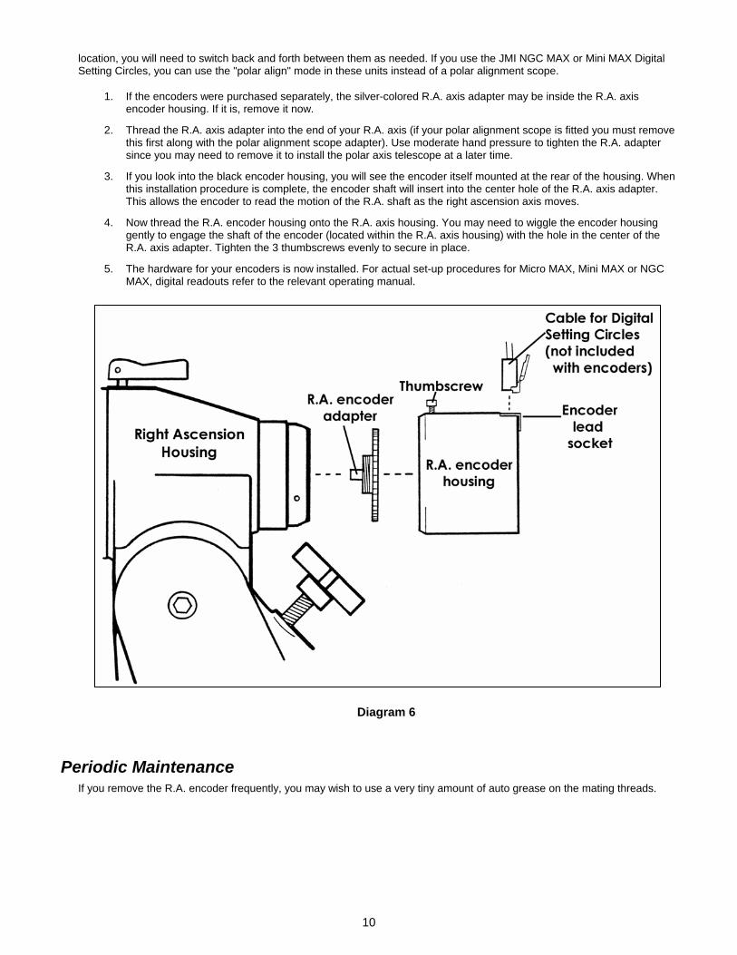
1. If the encoders were purchased separately, the silver-colored R.A. axis adapter may be inside the R.A. axis encoder housing. If it is, remove it now.
2. Thread the R.A. axis adapter into the end of your R.A. axis (if your polar alignment scope is fitted you must remove this first along with the polar alignment scope adapter). Use moderate hand pressure to tighten the R.A. adapter since you may need to remove it to install the polar axis telescope at a later time.
3. If you look into the black encoder housing, you will see the encoder itself mounted at the rear of the housing. When this installation procedure is complete, the encoder shaft will insert into the center hole of the R.A. axis adapter. This allows the encoder to read the motion of the R.A. shaft as the right ascension axis moves.
4. Now thread the R.A. encoder housing onto the R.A. axis housing. You may need to wiggle the encoder housing gently to engage the shaft of the encoder (located within the R.A. axis housing) with the hole in the center of the R.A. axis adapter. Tighten the 3 thumbscrews evenly to secure in place.
5. The hardware for your encoders is now installed. For actual set-up procedures for Micro MAX, Mini MAX or NGC MAX, digital readouts refer to the relevant operating manual.
Diagram 6
Periodic Maintenance If you remove the R.A. encoder frequently, you may wish to use a very tiny amount of auto grease on the mating threads.
10

POLAR ALIGNMENT TELESCOPE AND ILLUMINATOR The polar alignment telescope (also called polar axis scope) will help you to align your mount with the precise north celestial pole. If your mount is aligned properly, your drive motor will track celestial objects accurately throughout the night. This will allow you to sit back and enjoy the view without constantly adjusting your telescope to follow stars that are drifting continually out of your eyepiece. If you plan to take astrophotos, proper alignment is critical so that the images recorded on film are as tight and round as possible. Improper alignment will result in elongated star images. The polar alignment scope is for use in the Northern Hemisphere only.
This scope utilizes a special-condenser system, which makes it possible to view the entire reticle in a single glance. The reticle has a special setting pattern that makes alignment easy. The dark field illuminator is a red LED, which illuminates the reticle so it can be seen clearly against the night sky.
Polar Alignment Scope Specifications: Magnification: 5X Achromatic objective lens: 20mm Eyepiece: K22mm (Diopter adjustable) Field of view: 8 degrees Reticle: Condenser system setting pattern Accessory: Allen wrench (for M3 1.5mm, included)
Diagram 7
Illuminator Specifications: Rated voltage: 3VDC Power consumption: 16mA Light: red LED Battery: Button-type: two Varta V76 PX or equivalent Your camera dealer can help you. Radio Shack hearing aid battery, P675M cat. no. 23-145, pkg. of 6 for $2.79
Diagram 8
11
Installation and Adjustments We recommend that you install and adjust your polar alignment telescope in daylight, without the telescope and counterweights, following the instructions in this section. Once the reticle is properly adjusted so its center circle is mechanically and optically aligned with your mount, the alignment will remain stable, barring any strong shock to your mount.
1. Adjust the diopter: Loosen the diopter adjustment locking ring and turn eyepiece until the reticle is sharply in focus. Tighten the locking ring to lock the eyepiece in place.
2. Adjust the focus: Loosen the focusing adjustment locking ring and turn the objective tube until you get a sharply focused image of a distant object. Tighten this locking ring to lock the objective tube in place.
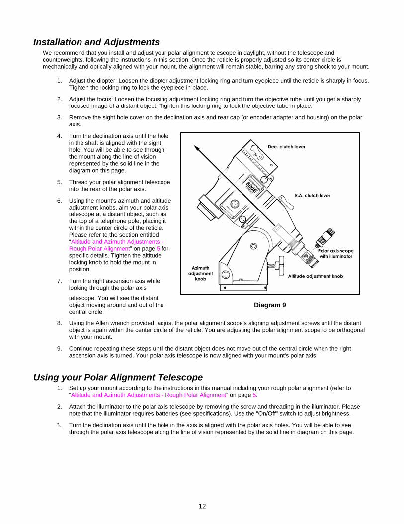
3. Remove the sight hole cover on the declination axis and rear cap (or encoder adapter and housing) on the polar axis.
4. Turn the declination axis until the hole in the shaft is aligned with the sight hole. You will be able to see through the mount along the line of vision represented by the solid line in the diagram on this page.
5. Thread your polar alignment telescope into the rear of the polar axis.
6. Using the mount's azimuth and altitude adjustment knobs, aim your polar axis telescope at a distant object, such as the top of a telephone pole, placing it within the center circle of the reticle. Please refer to the section entitled “Altitude and Azimuth Adjustments - Rough Polar Alignment” on page 5 for specific details. Tighten the altitude locking knob to hold the mount in position.
7. Turn the right ascension axis while looking through the polar axis
telescope. You will see the distant object moving around and out of the central circle.
Diagram 9
8. Using the Allen wrench provided, adjust the polar alignment scope's aligning adjustment screws until the distant object is again within the center circle of the reticle. You are adjusting the polar alignment scope to be orthogonal with your mount.
9. Continue repeating these steps until the distant object does not move out of the central circle when the right ascension axis is turned. Your polar axis telescope is now aligned with your mount's polar axis.
Using your Polar Alignment Telescope 1. Set up your mount according to the instructions in this manual including your rough polar alignment (refer to
“Altitude and Azimuth Adjustments - Rough Polar Alignment” on page 5.
2. Attach the illuminator to the polar axis telescope by removing the screw and threading in the illuminator. Please note that the illuminator requires batteries (see specifications). Use the "On/Off" switch to adjust brightness.
3. Turn the declination axis until the hole in the axis is aligned with the polar axis holes. You will be able to see through the polar axis telescope along the line of vision represented by the solid line in diagram on this page.
12
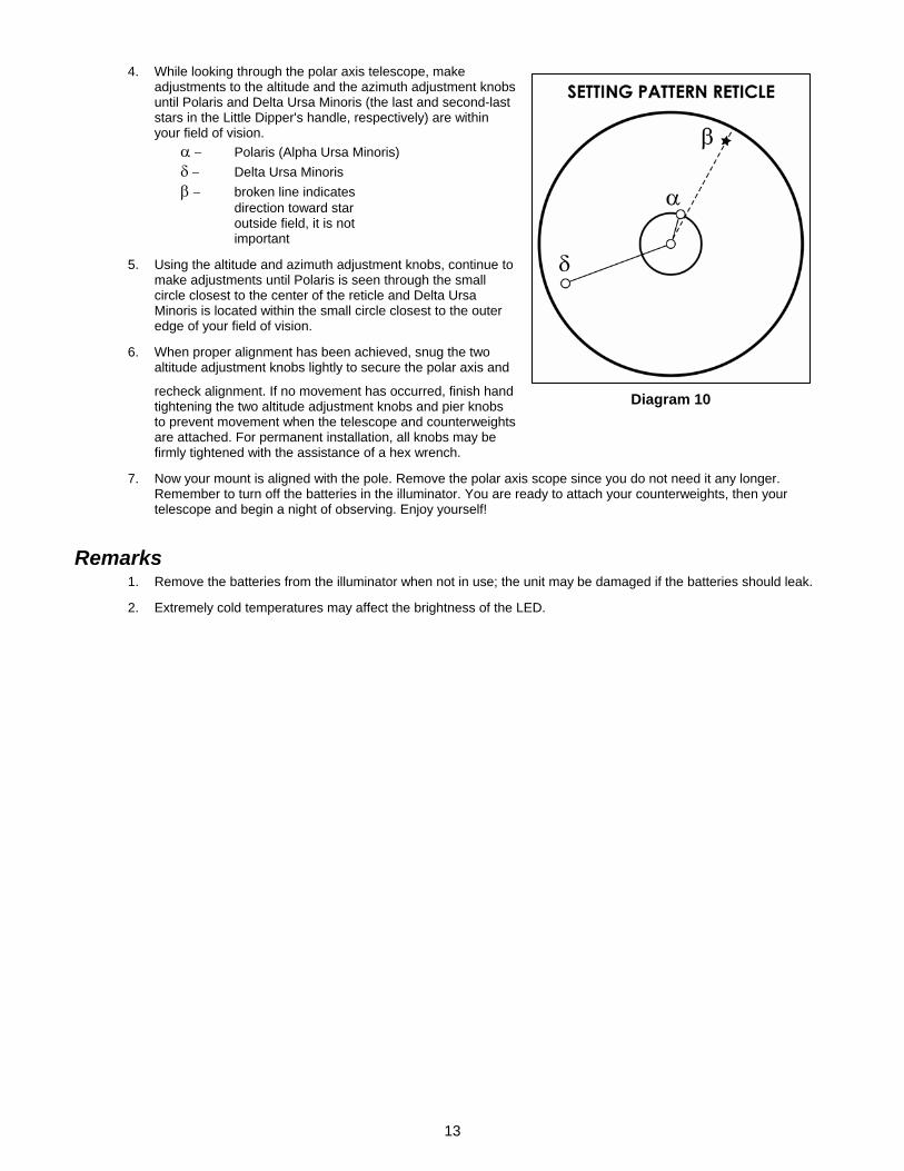
4. While looking through the polar axis telescope, make adjustments to the altitude and the azimuth adjustment knobs until Polaris and Delta Ursa Minoris (the last and second-last stars in the Little Dipper's handle, respectively) are within your field of vision. α − Polaris (Alpha Ursa Minoris) δ − Delta Ursa Minoris β − broken line indicates direction toward star outside field, it is not important
5. Using the altitude and azimuth adjustment knobs, continue to make adjustments until Polaris is seen through the small circle closest to the center of the reticle and Delta Ursa Minoris is located within the small circle closest to the outer edge of your field of vision.
6. When proper alignment has been achieved, snug the two altitude adjustment knobs lightly to secure the polar axis and
recheck alignment. If no movement has occurred, finish hand tightening the two altitude adjustment knobs and pier knobs to prevent movement when the telescope and counterweights are attached. For permanent installation, all knobs may be firmly tightened with the assistance of a hex wrench.
Diagram 10
7. Now your mount is aligned with the pole. Remove the polar axis scope since you do not need it any longer. Remember to turn off the batteries in the illuminator. You are ready to attach your counterweights, then your telescope and begin a night of observing. Enjoy yourself!
Remarks 1. Remove the batteries from the illuminator when not in use; the unit may be damaged if the batteries should leak.
2. Extremely cold temperatures may affect the brightness of the LED.
13


![t New CUBEs with Heavy Attitude t€¦ · METAL ZONE, EXTREME), GAIN Knob, VOLUME Knob, [EQUALIZER] BASS Knob, MIDDLE Knob, TREBLE Knob Indicators CLEAN Channel, LEAD Channel Connectors](https://img.pdfslide.us/doc/110x75/6067859789f730682b1d8a48/t-new-cubes-with-heavy-attitude-t-metal-zone-extreme-gain-knob-volume-knob.jpg)


![Removal and installation of counterweight assembly [For ... · Removal and installation of counterweight assembly [For machines with additional counterweight] (PC138-H700-924-K-00-A)](https://img.pdfslide.us/doc/110x75/5e7c187268933c73834968bc/removal-and-installation-of-counterweight-assembly-for-removal-and-installation.jpg)