Embed Size (px)
Citation preview
By Authority OfTHE UNITED STATES OF AMERICA
Legally Binding Document
By the Authority Vested By Part 5 of the United States Code § 552(a) and Part 1 of the Code of Regulations § 51 the attached document has been duly INCORPORATED BY REFERENCE and shall be considered legally binding upon all citizens and residents of the United States of America. HEED THIS NOTICE: Criminal penalties may apply for noncompliance.
Official Incorporator:THE EXECUTIVE DIRECTOROFFICE OF THE FEDERAL REGISTERWASHINGTON, D.C.
Document Name:
CFR Section(s):
Standards Body:
e

NOTICE: This standard has either been superseded and replaced by a new version or withdrawn. Contact ASTM International (www.astm.org) for Ihe lalesl information
~ Designation: D 1319 - 03
'u II INTERNATIONAL
IPqp Designation: 156/97
Standard Test Method for
An American National Standard
Hydrocarbon Types in Liquid Petroleum Products by Fluorescent Indicator Adsorption 1
This standard is issued under the fixed designatioD D 1319; the number immediately following the designation indicates the year of original adoption or, in the case of revision, the year of last revision. A number in parentheses indicates the year of last reapproval. A superscript epsilon (e) indicates an editorial change since the last revision or reapproval.
This stmuiard has been approved for use by agencies of the Department of Defense.
1. Scope*
1.1 This test method covers the determination of hydrocarbon types over the concentration ranges from 5 to 99 volume % aromatics, 0.3 to 55 volume % oletins, and 1 to 95 volume % saturates in petroleum fractions that distill below 315'C. This test method may apply to concentrations outside these ranges, but the precision has not been determined. Samples containing dark-colored components that interfere in reading the chromatographic bands cannot be analyzed.
1.2 This test method is intended for use with full boiling range products. Cooperative data have established that the precision statement does not apply to narrow boiling petroleum fractions near the 31SOC limit. Such samples are not eluted properly, and results are erratic.
1.3 The applicability of this test method to products derived from fossil fuels other than petroleum, such as coal, shale, or tar sands, has not been determined, and the precision statement mayor may not apply to such products.
1.4 This test method has two precision statements depicted in tables. The first table is applicable to unleaded fuels that do not contain oxygenated blending components. It mayor may not apply to automotive gasolines containing lead antiknock mixtures. The second table is applicable to oxygenate blended (for example, MfBE, ethanol) automotive spark ignition fuel samples with a concentration range of 13-40 volume percent aromatics, 4-33 volume percent olefins, and 45-68 volume percent saturates.
1.5 The oxygenated blending components, methanol, ethanol, methyl-tert-butylether (MTBE), tert-amylmethylether (TAME), and ethyl-tert-butylether (ETBE), do not interfere
1 Tills test method is under the juriSdiction of ASTM Committee D02 on Petroleum Products and Lubricants and is the direct responsibility of Subcommittee D02.04 on Hydrocarbon Analysis.
In the IP. this test method is under the jurisdiction of the Standardization Committee. This test method bas been approved by the sponsoring committees and accepted by the coopemting societies in accordance with established procedures.
Current edition approved Nov. 1, 2003. Published January 2004. Originally approved in 1954. Last previous edition approved in 2002 as D 1319-02a.
with the detemlination of hydrocarbon types at concentrations normally found in commercial blends. These oxygenated components are not detected since they elute with the alcohol desorbent. Other oxygenated compounds shall be individually verified. When samples containing oxygenated blending components are analyzed, correct the results to a total-sample basis.
1.6 The values stated in SI units are to be regarded as standard.
NOTE I-For the determination of olefins below 0.3 volume %. other test methods are available. such as Test Method D 2710.
1.7 This standard does not purport to address all of the safety concerns. if any. associated with its use. It is the responsibility of the user of this standard to establish appropriate safety and health practices and detennine the applicability a/regulatory limitations prior to use. For specific hazard statements. see Section 7, 8.1, and 10.5.
2. Referenced Documents
2.1 ASTM Standards: 2
D 86 Test Method for Distillation of Petroleum Products at Atmospheric Pressure
D 1655 Specification for Aviation Turbine Fuels D 2710 Test Method for Bromine Index of Petroleum Hy
drocarbons by Electrometric Titration D 3663 Test Method for Surface Area of Catalysts and
Catalyst Carriers D 4057 Practice for Manual Sampling of Petroleum and
Petroleum Products D 4815 Test Method for Determination of MTBE, ETBE,
TAME, DlPE, terliClly-Amyl Alcohol and C, to C4 Alcohols in Gasoline by Gas Chromatography
D 5599 Test Method for Determination of Oxygenates in Gasoline by Gas Chromatography and Oxygen Selective
:! For referenced ASTM standards, visit the ASTM website, www.astm.org, or contact ASTM Customer Service at [email protected]. For Anmlal Book Of ASTM Standards volume information, refer to the standard's Document Summary page on the ASTM website.
*A Swnmal"Y of Changes section appears at the end of this standard.
Copyright © ASTM Intemallonal.100BarrHarborDrive.POBoxC700.Wes!Conshohocken.PA1942a.2959. Untied States.
1
NOTICE: This standard has either been superseded and replaced by a new version or withdrawn. Contact ASTM International (www.astm.org) for Ihe lalesl information
~ Designation: D 1319 - 03
'u II INTERNATIONAL
IPqp Designation: 156/97
Standard Test Method for
An American National Standard
Hydrocarbon Types in Liquid Petroleum Products by Fluorescent Indicator Adsorption 1
This standard is issued under the fixed designatioD D 1319; the number immediately following the designation indicates the year of original adoption or, in the case of revision, the year of last revision. A number in parentheses indicates the year of last reapproval. A superscript epsilon (e) indicates an editorial change since the last revision or reapproval.
This stmuiard has been approved for use by agencies of the Department of Defense.
1. Scope* 1.1 This test method covers the determination of hydrocar
bon types over the concentration ranges from 5 to 99 volume % aromatics, 0.3 to 55 volume % oletins, and 1 to 95 volume % saturates in petroleum fractions that distill below 315'C. This test method may apply to concentrations outside these ranges, but the precision has not been determined. Samples containing dark-colored components that interfere in reading the chromatographic bands cannot be analyzed.
1.2 This test method is intended for use with full boiling range products. Cooperative data have establlshed that the precision statement does not apply to narrow boiling petroleum fractions near the 31SOC limit. Such samples are not eluted properly, and results are erratic.
1.3 The applicability of this test method to products derived from fossil fuels other than petroleum, such as coal, shale, or tar sands, has not been determined, and the precision statement mayor may not apply to such products.
1.4 This test method has two precision statements depicted in tables. The first table is applicable to unleaded fuels that do not contain oxygenated blending components. It mayor may not apply to automotive gasolines containing lead antiknock mixtures. The second table is applicable to oxygenate blended (for example, MfBE, ethanol) automotive spark ignition fuel samples with a concentration range of 13-40 volume percent aromatics, 4-33 volume percent olefins, and 45-68 volume percent saturates.
1.5 The oxygenated blending components, methanol, ethanol, methyl-tert-butylether (MTBE), tert-amylmethylether (TAME), and ethyl-tert-butylether (ETBE), do not interfere
1 Tills test method is under the jurisdiction of ASTM Committee D02 on Petroleum Products and Lubricants and is the direct responsibility of Subcommittee D02.04 on Hydrocarbon Analysis.
In the IP. this test method is under the jurisdiction of the Standardization Committee. This test method bas been approved by the sponsoring committees and accepted by the coopemting societies in accordance with established procedures.
Current edition approved Nov. 1, 2003. Published January 2004. Originally approved in 1954. Last previous edition approved in 2002 as D 1319-02a.
with the detemlination of hydrocarbon types at concentrations normally found in commercial blends. These oxygenated components are not detected since they elute with the alcohol desorbent. Other oxygenated compounds shall be individually verified. When samples containing oxygenated blending components are analyzed, correct the results to a total-sample basis.
1.6 The values stated in SI units are to be regarded as standard.
NOTE I-For the determination of olefius below 0.3 volume %, other test methods are available, such as Test Method D 2710.
1.7 This standard does not purport to address all of the safety concerns. if any. associated with its use. It is the responsibility of the user of this standard to establish appropriate safety and health practices and detennine the applicability a/regulatory limitations prior to use. For specific hazard statements. see Section 7, 8.1, and 10.5.
2. Referenced Documents 2.1 ASTM Standards: 2
D 86 Test Method for Distillation of Petroleum Products at Atmospheric Pressure
D 1655 Specification for Aviation Turbine Fuels D 2710 Test Method for Bromine Index of Petroleum Hy
drocarbons by Electrometric Titration D 3663 Test Method for Surface Area of Catalysts and
Catalyst Carriers D 4057 Practice for Manual Sampling of Petroleum and
Petroleum Products D 4815 Test Method for Determination of MTBE, ETBE,
TAME, DIPE, tertiClly-Amyl Alcohol and C, to C4 Alcohols in Gasollne by Gas Chromatography
D 5599 Test Method for Determination of Oxygenates in Gasoline by Gas Chromatography and Oxygen Selective
:! For referenced ASTM standards, visit the ASTM website, www.astm.org, or contact ASTM Customer Service at [email protected]. For Anlll/al Book Of ASTM Standards volume information, refer to the standard's Document Summary page on the ASTM website.
*A Swnmal'Y of Changes section appeal's at the end of this standal'd.
Copyright © ASTM Intemallonal.100BarrHarborDrive.POBoxC700.Wes!Conshohocken.PA1942a.2959. United States.
1
APT~) 01319 - 03 'l\ilW Flame Ionization Detection
E 11 Specification for Wire Cloth and Sieves for Testing Purposes
2.2 Other Standards: GCfOFID EPA Test Method-Oxygen and Oxygenate Con
tent Analysis3
BS410-1 2000 Test sieves. Technical requirements and testing. Test sieves of metal wire cloth4
3. Terminology
3.1 Definitions of Terms Specific to This Standard: 3.1.1 aromatics-the volume % of monocyclic and polycy
clic aromatics, plus aromatic olefins, some dienes, compounds containing sulfur and nitrogen, or higher boiling oxygenated compounds (excluding those listed in 1.5).
3.1.2 ole fins-the volume % of alkenes, plus cycloalkenes, and some dienes.
3.1.3 saturates-the volume % of alkanes, plus cycloalkanes.
4. Summary of Test Method
4.1 Approximately 0.75 mL of sample is introduced into a special glass adsorption column packed with activated silica gel. A small layer of the silica gel contains a mixture of fluorescent dyes. When all the sample has been adsorbed on the gel. alcohol is added to desorb the sample down the column. The hydrocarbons are separated in accordance with their adsorption affinities into aromatics, oletins, and saturates. The fluorescent dyes arc also separated selectively, with the hydrocarbon types, and make the boundaries of the aromatic, olefin, _and saturate zones visible under ultraviolet light. The volume percentage of each hydrocarbon type is calculated from the length of each zone in the column.
5. Significance and Use
5.1 The determination of the total volume % of saturates, olefins, and aromatics in petroleum fractions is important in characterizing the quality of petroleum fractions as gasoline blending components and as feeds to catalytic reforming processes. This information is also important in characterizing petroleum fractions and products from catalytic reforming and from thermal and catalytic cracking as blending components for motor and aviation fuels. This information is also important as a measure of the quality of fuels, such as specified in Specification D 1655.
6. Apparatus
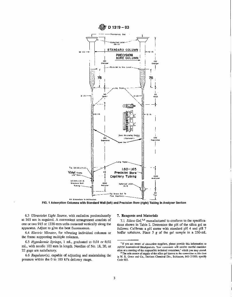
6.1 Adsolption Columns, with precision bore ("true bore" IP designation) tubing, as shown on the right in Fig. 1, made of glass and consisting of a charger section with a capillary neck, a separator section, and an analyzer section; or with standard wall mbing, as shown on the left in Fig. 1. Refer to Table 1 for column tolerance limits.
3 Code of Federal Regulations, Pmt 80 of Title 40, 80.46 (g); also published in the Federal Register, Vol 59. No. 32, Feb. 16, 1994, p. 7828. No longer available.
4 Available from Britisih Standards Institution CBS!) Customer Services, 389 Chiswick High Road, London, W4 4AL
2
6.1.1 The inner diameter of the analyzer section for the precision bore tubing shall be 1.60 to 1.65 mm. In addition the length of an approximately 100-mm thread of mercury shall not vary by more than 0.3 mm in any part of the analyzer section. In glass-sealing the various sections to each other. long-taper connections shall be made instead of shouldered connections. Support the silica gel with a small piece of glass wool located between the ball and socket of the 12/2 spherical joint and covering the analyzer outlet. The column tip attached to the 1212 socket shall have a 2-mm internal diameter. Clamp the ball and socket together and ensure that the tip does not tend to slide from a position in a direct line with the analyzer section during the packing and subsequent use of the column. Commercial compression-type connectors may be used to couple the bottom of the separator section (which has been cut square), to the disposable 3-rnm analyzer section, provided that the internal geometry is essentially similar to the aforementioned procedure and provides for a smooth physical transition from the inner diameters of the two glass colunm sections. Similar commercial compression-type connectors may be employed at the terminal end of the 3-nun analyzer section, having an integral porous support to retain the silica gel.
6.1.2 For convenience, adsorption columns with standard wall tubing, as shown on the left in Fig. 1, can be used. When using standard wall tubing for the analyzer section, it is necessary to select tubing of unifonn bore and to provide a leakproof connection between the separator and the analyzer sections. Calibrations of standard wall tubing would be impractical; however, any variations of 0.5 nun or greater, as measured by ordinary calipers, in the outside diameter along the tube can be taken as an indication of irregularities in the inner diameter and such tubing should not be used. Prepare the glassware to retain the gel. One way to accomplish this is to draw out one end of the tubing selected for the analyzer section to a fine capillary. Connect the other end of the analyzer section to the separator section with a suitable length of vinyl tubing, making certain that the two glass sections touch. A 30 ± 5 mm length of vinyl tubing has been found to be suitable. To ensure a leakproof glass-to-vinyl seal with the analyzer section, it is necessary to heat the upper end of the analyzer section until it is just hot enough to melt the vinyl, then insert the upper end of the analyzer section into the vinyl sleeve. Alternatively, this seal can be made by securing the vinyl sleeve to the analyzer section by wrapping it tightly with soft wire. Commercial compression-type connectors may be used to couple the bottom of the separator section (which has been cut square), to the 3-mm analyzer section, provided that the internal geometry is essentially similar to the aforementioned procedure and provides for a smooth physical transition from the inner diameters of the two glass column sections.
6.2 Zone-Measuring Device-The zones may be marked with a glass-writing pencil and the distances measured with a meter rule, with the analyzer section lying horizontally. Alternatively, the meter rule may be fastened adjacent to the column. In this case, it is convenient to have each rule fitted with four movable metal index clips (Fig. 1) for marking zone boundaries and measuring the length of each zone.
APT~) 01319 - 03 'l\ilW Flame Ionization Detection
E 11 Specification for Wire Cloth and Sieves for Testing Purposes
2.2 Other Standards: GCfOFID EPA Test Method-Oxygen and Oxygenate Con
tent Analysis3
BS410-1 2000 Test sieves. Technical requirements and testing. Test sieves of metal wire cloth4
3. Terminology
3.1 Definitions of Terms Specific to This Standard: 3.1.1 aromatics-the volume % of monocyclic and polycy
clic aromatics, plus aromatic olefins, some dienes, compounds containing sulfur and nitrogen, or higher boiling oxygenated compounds (excluding those listed in 1.5).
3.1.2 ole fins-the volume % of alkenes, plus cycloalkenes, and some dienes.
3.1.3 saturates-the volume % of alkanes, plus cycloalkanes.
4. Summary of Test Method
4.1 Approximately 0.75 mL of sample is introduced into a special glass adsorption column packed with activated silica gel. A small layer of the silica gel contains a mixture of fluorescent dyes. When all the sample has been adsorbed on the gel. alcohol is added to desorb the sample down the column. The hydrocarbons are separated in accordance with their adsorption affinities into aromatics, oletins, and saturates. The fluorescent dyes arc also separated selectively, with the hydrocarbon types, and make the boundaries of the aromatic, olefin, _and saturate zones visible under ultraviolet light. The volume percentage of each hydrocarbon type is calculated from the length of each zone in the column.
5. Significance and Use
5.1 The determination of the total volume % of saturates, olefins, and aromatics in petroleum fractions is important in characterizing the quality of petroleum fractions as gasoline blending components and as feeds to catalytic reforming processes. This information is also important in characterizing petroleum fractions and products from catalytic reforming and from thermal and catalytic cracking as blending components for motor and aviation fuels. This information is also important as a measure of the quality of fuels, such as specified in Specification D 1655.
6. Apparatus
6.1 Adsolption Columns, with precision bore ("true bore" IP designation) tubing, as shown on the right in Fig. 1, made of glass and consisting of a charger section with a capillary neck, a separator section, and an analyzer section; or with standard wall mbing, as shown on the left in Fig. 1. Refer to Table 1 for column tolerance limits.
3 Code of Federal Regulations, Pmt 80 of Title 40, 80.46 (g); also published in the Federal Register, Vol 59. No. 32, Feb. 16, 1994, p. 7828. No longer available.
4 Available from Britisih Standards Institution CBS!) Customer Services, 389 Chiswick High Road, London, W4 4AL
2
6.1.1 The inner diameter of the analyzer section for the precision bore tubing shall be 1.60 to 1.65 mm. In addition the length of an approximately 100-mm thread of mercury shall not vary by more than 0.3 mm in any part of the analyzer section. In glass-sealing the various sections to each other. long-taper connections shall be made instead of shouldered connections. Support the silica gel with a small piece of glass wool located between the ball and socket of the 12/2 spherical joint and covering the analyzer outlet. The column tip attached to the 1212 socket shall have a 2-mm internal diameter. Clamp the ball and socket together and ensure that the tip does not tend to slide from a position in a direct line with the analyzer section during the packing and subsequent use of the column. Commercial compression-type connectors may be used to couple the bottom of the separator section (which has been cut square), to the disposable 3-rnm analyzer section, provided that the internal geometry is essentially similar to the aforementioned procedure and provides for a smooth physical transition from the inner diameters of the two glass colunm sections. Similar commercial compression-type connectors may be employed at the terminal end of the 3-nun analyzer section, having an integral porous support to retain the silica gel.
6.1.2 For convenience, adsorption columns with standard wall tubing, as shown on the left in Fig. 1, can be used. When using standard wall tubing for the analyzer section, it is necessary to select tubing of unifonn bore and to provide a leakproof connection between the separator and the analyzer sections. Calibrations of standard wall tubing would be impractical; however, any variations of 0.5 nun or greater, as measured by ordinary calipers, in the outside diameter along the tube can be taken as an indication of irregularities in the inner diameter and such tubing should not be used. Prepare the glassware to retain the gel. One way to accomplish this is to draw out one end of the tubing selected for the analyzer section to a fine capillary. Connect the other end of the analyzer section to the separator section with a suitable length of vinyl tubing, making certain that the two glass sections touch. A 30 ± 5 mm length of vinyl tubing has been found to be suitable. To ensure a leakproof glass-to-vinyl seal with the analyzer section, it is necessary to heat the upper end of the analyzer section until it is just hot enough to melt the vinyl, then insert the upper end of the analyzer section into the vinyl sleeve. Alternatively, this seal can be made by securing the vinyl sleeve to the analyzer section by wrapping it tightly with soft wire. Commercial compression-type connectors may be used to couple the bottom of the separator section (which has been cut square), to the 3-mm analyzer section, provided that the internal geometry is essentially similar to the aforementioned procedure and provides for a smooth physical transition from the inner diameters of the two glass column sections.
6.2 Zone-Measuring Device-The zones may be marked with a glass-writing pencil and the distances measured with a meter rule, with the analyzer section lying horizontally. Alternatively, the meter rule may be fastened adjacent to the column. In this case, it is convenient to have each rule fitted with four movable metal index clips (Fig. 1) for marking zone boundaries and measuring the length of each zone.
12 10.--_
• D 1319-03
~---s~".ri.nl Jainr-----211112
e- T I i I
STANDARD COLUMN i ~_''''.: PRECISION '
ISO 150 1
I BORE COLUMN :
I 1;;110'9.< Chllf~.r
(
. I r -1,--'''' ", .... " ""'-]" - f I : '[ f.s, 75 ,". I I if I ' J I " L [ If _t" Lr"' ; .. "'\~ " 11i' ~ I 50 / ,II[ '0
""1 )'~'- ~ '~ 'i" !, / ,II j rr-- ~:j--t
j ., I'~: j-" , ~ ;-:
'" S.parllIQ'
I
I
Zan~ Me05UrLnQ Device {?J (Oprional )~.~;.' ___ I'"'
Dyed Gel .~
I~"., "'" -i 1.60-1,65 TiP. 3.5 O.D.I 2 loO.
Vinyl Tubing 1/11" Sin
25 Precis ion Bore' - _I Capillary Tubing f Anol,,,,
3.0 0.11. x le 1.0. I I Slanda'd Wan IlOO Sph~"cul Juint
TUb'"9~: Anolynr . 12/2 ____ 1 i , _Tip Ora" .. Out To .:.~
Flnc 001',110', ----_:11 I All Dimen.iana In Mjl1ln>eI.'~ _----L
FIG. 1 Adsorption Columns with Standard Wall (left) and Precision Bore (right) Tubing in Analyzer Section
6,3 Ultraviolet Light Source, with radiation predominantly at 365 nm is required. A convenient arrangement consists of one or two 915 or 1220-mm units mounted vertically along the apparatus. Adjust to give the best fluorescence.
6.4 Electric Vibrator, for vibrating individual columns or the frame supporting multiple columns.
6.5 Hypodermic Syringe, 1 mL, graduated to 0,01 or 0,02 mL, with needle 102 mm in length. Needles of No, 18, 20, or 22 gage are satisfactory,
6,6 Regulator(s), capable of adjusting and maintaining the pressure within the ° to 103 kPa delivery range,
3
7, Reagents and Materials
7.1 Silica Gel,5,6 manufactured to conform to the specifications shown in Table 2. Determine the pH of the silica gel as follows: Calibrate a pH meter with standard pH 4 and pH 7 buffer solutions, Place 5 g of the gel sample in a 250-mL
~ If you are aware of alternative suppliers, please provide this information to ASTM International Headquarters. Your comments will receive careful consideration at a meeting of the responsible technical committee, l which you may attend
'" The sole source of supply of the silica gellmown to the committee at this time is W. R Grace and Co., Davison Chemical Div., Baltimore, MD 21203; specify Code 923.
12 10.--_
• D 1319-03
~---s~".ri.nl Jainr-----211112
e- T I i I
STANDARD COLUMN i ~_''''.: PRECISION '
ISO 150 1
I BORE COLUMN :
I 1;;110'9.< Chllf~.r
(
. I r -1,--'''' ", .... " ""'-]" - f I : '[ f.s, 75 ,". I I if I ' J I " L [ If _t" Lr"' ; .. "'\~ " 11i' ~ I 50 / ,II[ '0
""1 )'~'- ~ '~ 'i" !, / ,II j rr-- ~:j--t
j" I'~: 1-" , ~ ;-:
'" S.parllIQ'
I
I
Zan~ Me05UrLnQ Device {?J (Oprional )~.~;.' ___ I'"'
Dyed Gel .~
I~"., "'" -i 1.60-1,65 TiP. 3.5 O.D.I 2 loO.
Vinyl Tubing 1/11" Sin
25 Precis ion Bore' - _I Capillary Tubing f Anol,,,,
3.0 0.11. x le 1.0. I I Slanda'd Wan IlOO Sph~"cul Juint
TUb'"9~: Anolynr . 12/2 ____ 1 i , _Tip Ora" .. Out To .:.~
Flnc 001',110', ----_~l I All Dimen.iana In Mjl1ln>eI.'~ _----L
FIG. 1 Adsorption Columns with Standard Wall (left) and Precision Bore (right) Tubing in Analyzer Section
6,3 Ultraviolet Light Source, with radiation predominantly at 365 nm is required. A convenient arrangement consists of one or two 915 or 1220-mm units mounted vertically along the apparatus. Adjust to give the best fluorescence.
6.4 Electric Vibrator, for vibrating individual columns or the frame supporting multiple columns.
6.5 Hypodermic Syringe, 1 mL, graduated to 0,01 or 0,02 mL, with needle 102 mm in length. Needles of No, 18, 20, or 22 gage are satisfactory,
6,6 Regulator(s), capable of adjusting and maintaining the pressure within the ° to 103 kPa delivery range,
3
7, Reagents and Materials
7.1 Silica Gel,5,6 manufactured to conform to the specifications shown in Table 2. Determine the pH of the silica gel as follows: Calibrate a pH meter with standard pH 4 and pH 7 buffer solutions, Place 5 g of the gel sample in a 250-mL
~ If you are aware of alternative suppliers, please provide this information to ASTM International Headquarters. Your comments will receive careful consideration at a meeting of the responsible technical committee, l which you may attend
'" The sole source of supply of the silica gellmown to the committee at this time is W. R Grace and Co., Davison Chemical Div., Baltimore, MD 21203; specify Code 923.
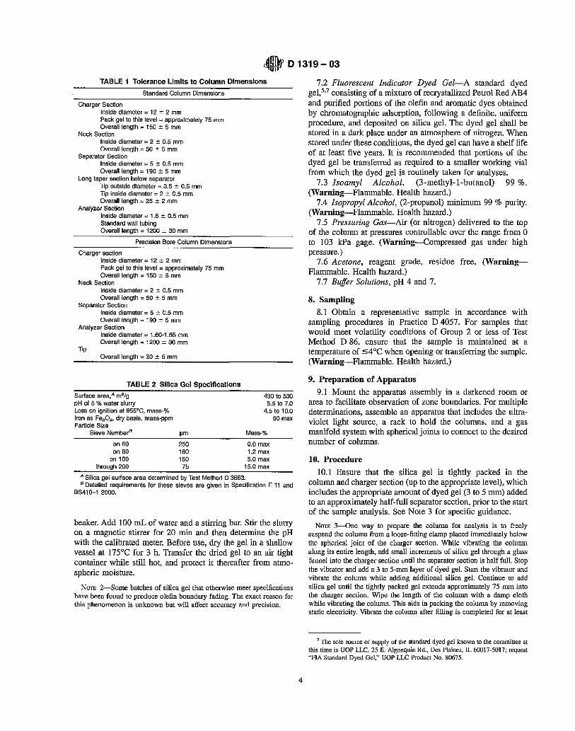
• D 1319-03 TABLE 1 Tolerance Limits to Column Dimensions
Standard Column Dimensions
Charger Section Inside diameter = 12 ~ 2 mm Pack gel to this level =' approximately 75 mm Overall length :: ISO:!: 5 mm
Neck Section Inside diameter = 2 ::':: 0.5 mm Overall length", 50 ± 5 mm
Separator Section Inside diameter = 5 :!: 0.5 mm Overall length:: 190 ::!: 5 mm
Long taper section below separator Tip outside diameter", 3.5 ± 0.5 mm TIp inside diameter = 2 :!: 0.5 mm Overall length = 25 :!: 2 mm
Analyzer Section Inside diameter = 1.5 ± 0.5 mm Standard wall tubing Overall length :: 1200 ± 30 mm
Precision Bore Column Dimensions
Charger section Inside diameter:: 12 :!:: 2 mm Pack gel to this level:: approximately 75 mm Overall length ::: 150 ± 5 mm
Neck Section Inside diameter = 2 ± 0.5 mm Overall length = 50 ± 5 mm
Separator Section Inside diameter = 5 ± 0.5 mm OVerall length = 190 ± 5 mm
Analyzer Section
11p
Inside diameter = 1.60-1.65 mm Overall length = 1200 ± 30 mm
Overall length = 30 ± 5 mm
TABLE 2 Silica Gel Specifications
Surface area,A m2/g pH of 5 % water slurry Loss on ignition at 955~C, mass-% Iron as Fe2D:;h dry basis, mass-ppm Particle Size
Sieve NumberB 11m
on 60 250 on 80 180
on 100 150 through 200 75
430 to 530 5.5 to 7.0
4.5 to 10.0
Mass-%
0.0 max 1.2 max 5.0 max
15.0 max
50 max
A Silica gel surface area determined by Test Method D 3663. B Detailed requirements for these sieves are given in Specification E 11 and
8S410-1 2000.
beaker. Add 100 mL of water and a stirring bar. Stir the slurry on a magnetic stirrer for 20 min and then determine the pH with the calibrated meter. Before use, dry the gel in a shallow vessel at 175°C for 3 h. Transfer the dried gel to an air tight container while still hot, and protect it thereafter from atmospheric moisture.
NOTE 2-Some batches of silica gel that otherwise meet specifications have been found to produce olefin boundary fading. The exact reason for this phenomenon is unknown but will affect accuracy and precision.
4
7.2 Fluorescent Indicator Dyed Gel-A standard dyed gel,S,7 consisting of a mixture of recrystallized Petrol Red AB4 and purified portions of the olefin and aromatic dyes obtained by chromatographic adsorption, following a definite. uniform procedure. and deposited on silica gel. The dyed gel shall be stored in a dark place under an atmosphere of nitrogen. When stored under these conditions, the dyed gel can have a shelf life of at least five years. It is recommended that portions of the dyed gel be transferred as required to a smaller working vial from which the dyed gel is routinely taken for analyses.
7.3 Isoamyl Alcohol, (3-methyl-l-butanol) 99 %. (Warning-Flammable. Health hazard.)
7.4 Isopropyl Alcohol, (2-propanol) minimum 99 % purity. (Warning-Flammable. Health hazard.)
7.5 Presswing Gas-Air (or nitrogen) delivered to the top of the column at pressures controllable over the range from 0 to 103 kPa gage. (Warning-Compressed gas under high pressure.)
7.6 Acetone, reagent grade, residue free. (WarningFlammable. Health hazard.)
7.7 Buffer Solutions, pH 4 and 7.
8. Sampling
8.1 Obtain a representative sample in accordance with sampling procedures in Practice D 4057. For samples that would meet volatility conditions of Group 2 or less of Test Method D 86, ensure that the sample is maintained at a temperature of """;4°C when opening or transferring the sample. (Warning-Flammable. Health hazard.)
9. Preparation of Apparatus
9.1 Mount the apparatus assembly in a darkened room or area to facilitate observation of zone boundaries. For multiple determinations, assemble an apparatus that includes the ultraviolet light source, a rack to hold the columns. and a gas manifold system with spherical joints to connect to the desired number of columns.
10. Procedure
10.1 Ensure that the silica gel is tightly packed in the column and charger section (up to the appropriate level), which includes the appropriate amount of dyed gel (3 to 5 mm) added to an approximately half-full separator section, prior to the start of the sample analysis. See Note 3 for specific guidance.
NOTE 3-One way to prepare the column for analysis is to freely suspend the column from a loose-fitting clamp placed immediately below the spherical joint of the charger section. While vibrating the column along its entire length, add small increments of silica gel through a glass funnel into the charger section until the separator section is half full. Stop the vibrator and add a 3 to 5-mm layer of dyed gel. Start the vibrator and vibrate the column while adding additional silica gel. Continue to add silica gel until the tightly packed gel extends approximately 75 mm into the charger section. Wipe the length of the column with a damp cloth while vibrating the column. This aids in packing the column by removing static electricity. Vibrate the colnmn after filling is completed for at least
7 The sole source of supply of the standard dyed gel known to the committee at this time is UOP LLC, 25 E. Algonquin Rd., Des Plaines, II.. 60017-5017; request "FIA Standard Dyed Gel," UOP LLC Product No. 80675.
• D 1319-03
4 min. More than one column can be prepared simultaneously by mounting several on a frame or rack to. which. an electric vibrator is attached.
10.2 Attach the filled column to the apparatus assembly in the darkened room or area, and when a permanently mounted meter rule is used, fasten the lower end of the column to the fixed rule with a rubber band.
10.3 For samples that would meet volatility conditions of Group 2 or less of Test Method D 86, chill the sample and a hypodermic syringe to less than 4 "C. Draw 0.75 :!: 0.03 mL of sample into the syringe and inject the sample approximately 30 mm below the surface of the gel in the charger section.
10.4 Fill the charger section to the spherical joint with isopropyl alcohol. Connect the column to the gas manifold and apply 14 :!: 2 kPa gas pressure for 2.5 ± 0.5 min to move the liquid front down the column. Increase the pressure to 34 ± 2 kPa gage for another 2.5 :!: 0.5 min and then adjust the pressure required to give a transit time of about I h. Usually a gas pressure of 28 to 69 kPa gage is needed for gasoline-type samples and 69 to 103 kPa gage for jet fuels. The pressure required will depend on the tightness of packing of the gel and the molecular weight of the sample. A transit time of I h is optimum; however, high-molecular weight samples may require longer transit times.
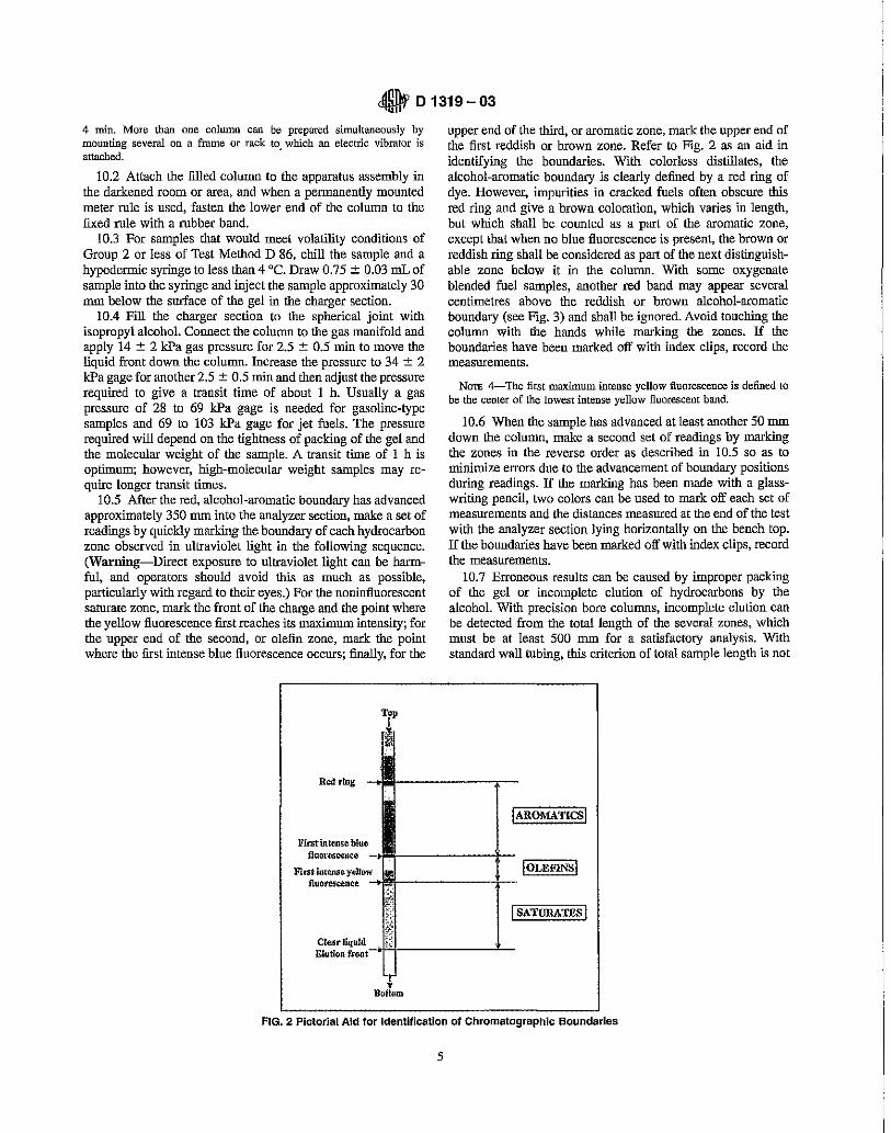
10.5 After the red, alcohol-aromatic boundary has advanced approximately 350 mm into the analyzer section, make a set of readings by quickly marking the boundary of each hydrocarbon zone observed in ultraviolet light in the following sequence. (Warning-Direct exposure to ultraviolet light can be harmful, and operators should avoid this as much as possible, particularly with regard to their eyes.) For the noninfluorescent saturate zone, mark the front of the charge and the point where the yellow fluorescence first reaches its maximum intensity; for the upper end of the second, or olefin zone, mark the point where the first intense blue fluorescence occurs; finally, for the
Top
Red ring -40
First intense. blue fi"{)rtlS~lIte -
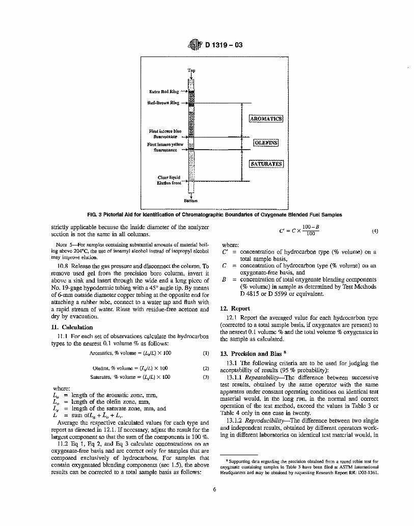
upper end of the third, or aromatic zone, mark the upper end of the first reddish or brown zone. Refer to Fig. 2 as an aid in identifying the boundaries. With colorless distillates, the alcohol-aromatic boundary is clearly defined by a red ring of dye. However, impurities in cracked fuels often obscure this red ring and give a brown coloration, which varies in length, but which shall be counted as a part of the aromatic zone, except that when no blue fluorescence is present, the brown or reddish ring shall be considered as part of the next distinguishable zone below it in the column. With some oxygenate blended fuel samples, another red band may appear several centimetres above the reddish or brown alcohol-aromatic boundary (see Fig. 3) and shall be iguored. Avoid touching the column with the hands while marking the zones. If the boundaries have been marked off with index clips, record the measurements.
NOTE 4-The first maximum intense yellow fluorescence is defined to be the center of the lowest intense yellow fluorescent band.
10.6 When the sample has advanced at least another 50 mm down the column, make a second set of readings by marking the zones in the reverse order as described in 10.5 so as to minimize errors due to the advancement of boundary positions during readings. If the marking has been made with a glasswriting pencil, two colors can be used to mark off each set of measurements and the distances measured at the end of the test with the analyzer section lying horizontally on the bench top. If the boundaries have been marked off with index clips, record the measurements.
10.7 Erroneous results can be caused by improper packing of the gel or incomplete elution of hydrocarbons by the alcohoL With precision bore columns, incomplete elution can be detected from the total length of the several zones, which must be at least 500 nun for a satisfactory analysis. With standard wall tubing, this criterion of total sample length is not
IAROMATIcsl
Fint intense. yellow I OLEFINS I fluorescence -I!i!!-------l:-
iSATURATESI
CleJlr iiquid _..J"h,'j. ______ -''-Elutionrront
'1 Bottom
FIG. 2 Pictorial Aid for Identification of Chromatographic Boundaries
5
• D 1319-03
4 min. More than one column can be prepared simultaneously by mounting several on a frame or rack to. which. an electric vibrator is attached.
10.2 Attach the filled column to the apparatus assembly in the darkened room or area, and when a permanently mounted meter rule is used, fasten the lower end of the column to the fixed rule with a rubber band.
10.3 For samples that would meet volatility conditions of Group 2 or less of Test Method D 86, chill the sample and a hypodermic syringe to less than 4 "C. Draw 0.75 :!: 0.03 mL of sample into the syringe and inject the sample approximately 30 mm below the surface of the gel in the charger section.
10.4 Fill the charger section to the spherical joint with isopropyl alcohol. Connect the column to the gas manifold and apply 14 :!: 2 kPa gas pressure for 2.5 ± 0.5 min to move the liquid front down the column. Increase the pressure to 34 ± 2 kPa gage for another 2.5 :!: 0.5 min and then adjust the pressure required to give a transit time of about I h. Usually a gas pressure of 28 to 69 kPa gage is needed for gasoline-type samples and 69 to 103 kPa gage for jet fuels. The pressure required will depend on the tightness of packing of the gel and the molecular weight of the sample. A transit time of I h is optimum; however, high-molecular weight samples may require longer transit times.
10.5 After the red, alcohol-aromatic boundary has advanced approximately 350 mm into the analyzer section, make a set of readings by quickly marking the boundary of each hydrocarbon zone observed in ultraviolet light in the following sequence. (Warning-Direct exposure to ultraviolet light can be harmful, and operators should avoid this as much as possible, particularly with regard to their eyes.) For the noninfluorescent saturate zone, mark the front of the charge and the point where the yellow fluorescence first reaches its maximum intensity; for the upper end of the second, or olefin zone, mark the point where the first intense blue fluorescence occurs; finally, for the
Red ring --,Ii
First intense. blue fi"{)rtlS~lIte -
Top
upper end of the third, or aromatic zone, mark the upper end of the first reddish or brown zone. Refer to Fig. 2 as an aid in identifying the boundaries. With colorless distillates, the alcohol-aromatic boundary is clearly defined by a red ring of dye. However, impurities in cracked fuels often obscure this red ring and give a brown coloration, which varies in length, but which shall be counted as a part of the aromatic zone, except that when no blue fluorescence is present, the brown or reddish ring shall be considered as part of the next distinguishable zone below it in the column. With some oxygenate blended fuel samples, another red band may appear several centimetres above the reddish or brown alcohol-aromatic boundary (see Fig. 3) and shall be iguored. Avoid touching the column with the hands while marking the zones. If the boundaries have been marked off with index clips, record the measurements.
NOTE 4-The first maximum intense yellow fluorescence is defined to be the center of the lowest intense yellow fluorescent band.
10.6 When the sample has advanced at least another 50 mm down the column, make a second set of readings by marking the zones in the reverse order as described in 10.5 so as to minimize errors due to the advancement of boundary positions during readings. If the marking has been made with a glasswriting pencil, two colors can be used to mark off each set of measurements and the distances measured at the end of the test with the analyzer section lying horizontally on the bench top. If the boundaries have been marked off with index clips, record the measurements.
10.7 Erroneous results can be caused by improper packing of the gel or incomplete elution of hydrocarbons by the alcohoL With precision bore columns, incomplete elution can be detected from the total length of the several zones, which must be at least 500 nun for a satisfactory analysis. With standard wall tubing, this criterion of total sample length is not
IAROMATIcsl
Fint intense. yellow I OLEFINS I fluorescence ->ii!i!f-------i-
~ iSATURATESI
CleJlr iiquid -..rho,!· ______ --"_ Elutionrront
• Bottom
FIG. 2 Pictorial Aid for Identification of Chromatographic Boundaries
5
0 01319-03
T •• I
,J"
Extra RedRlng -"1
Red-Brown Ring -.
First intense ,blue
IAROMATlcsl
fi .. "",,,, .. ~~ --+1 First int~ge yellow ;:.' t IOLEFINSj
fluorescence .... ~7"!iiI----------!.-
1 SATURATES 1
CI .. "iquld 1"'1 • Elution front A
1 • BoUom
FIG. 3 Pictorial Aid for Identification of Chromatographic Boundaries of Oxygenate Blended Fuel Samples
strictly applicable because the inside diameter of the analyzer section is not the same in all colunms.
NOTE 5-For samples containing substantial amounts of material boiling above 204°C, the use of isoamyl alcohol instead of isopropyl alcohol may improve elution.
10.8 Release the gas pressure and disconnect the column. To remove used gel from the precision bore column, invert it above a sink and insert through the wide end a long piece of No. 19·9age hypodermic tubing with a 45° angle tip. By means of 6-mm outside diameter copper tubing at the opposite end for attaching a rubber tube, connect to a water tap and flush with a rapid stream of water. Rinse with residue-free acetone and dry by evacuation.
11. Calculation
11.1 For each set of observations calculate the hydrocarbon types to the nearest 0.1 volume % as follows:
where:
Aromatics, % volume = (LjL) X 100
Olefins, % volume = (LolL) X 100
Saturates, % volume = (L)L) X 100
La = length of the aromatic zone, mm, Lo length of the olefin zone, nun, Ls length of the sarurate zone, mm, and L = sum ofLa + Lo + Ls.
(J)
(2)
(3)
Average the respective calculated values for each type and report as directed in 12.1. If necessary, adjust the result for the largest component so that the sum of the components is 100 %.
11.2 Eq I, Eq 2, and Eq 3 calculate concentrations on an oxygenate-free basis and are correct only for samples that are composed exclusively of hydrocarbons. For samples that contain oxygenated blending components (see 1.5), the above results can be corrected to a total sample basis as follows:
6
where:
IOO-B C' = C X ---roo (4)
C' = concentration of hydrocarbon type (% volume) on a total sample basis,
C = concentration of hydrocarbon type (% volume) on an oxygenate-free basis, and
B concentration of total oxygenate blending components (% volume) in sample as determined by Test Methods D 4815 or D 5599 or equivalent.
12. Report
12.1 Report the averaged value for each hydrocarbon type (corrected to a total sample basis, if oxygenates are present) to the nearest 0.1 volume % and the total volume % oxygenates in the sample as calculated.
13. Precision and Bias 8
13.1 The following criteria are to be used for judging the acceptability of results (95 % probability):
13.1.1 Repeatability--The difference between successive test results, obtained by the same operator with the same apparatus under constant operating conditions on identical test material WOUld, in the long run, in the normal and correct operation of the test method, exceed the values in Table 3 or Table 4 only in one case in twenty.
13.1.2 Reproducibility-The difference between two single and independent results, obtained by different operators working in different laboratories on identical test material would, in
8 Supporting data regarding the precision obtained from a round robin test for oxygenate containing samples in Table 3 have been filed at ASTM International Headquarlers and may be obtained by requesting Research Report RR: D02-1361.
0 01319-03
;:J T ••
t Extra RedRlng -+
Red-Brown Ring ->
First intense ,blue fluurel;Ieen.«: -I
First int~ge yellow fluorescence -I
Clear liquid Elution fron ,
"
I AROMATICS I
i IOLEFlNsl
I SATURATES I
FIG. 3 Pictorial Aid for Identification of Chromatographic Boundaries of Oxygenate Blended Fuel Samples
strictly applicable because the inside diameter of the analyzer section is not the same in all colunms.
NOTE 5-For samples containing substantial amounts of material boiling above 204°C, the use of isoamyl alcohol instead of isopropyl alcohol may improve elution.
10.8 Release the gas pressure and disconnect the column. To remove used gel from the precision bore column, invert it above a sink and insert through the wide end a long piece of No. 19-9age hypodermic tubing with a 45° angle tip. By means of 6-mm outside diameter copper tubing at the opposite end for attaching a rubber tube, connect to a water tap and flush with a rapid stream of water. Rinse with residue-free acetone and dry by evacuation.
11. Calculation
11.1 For each set of observations calculate the hydrocarbon types to the nearest 0.1 volume % as follows:
where:
Aromatics, % volume = (LjL) X 100
Olefins, % volume = (LolL) X 100
Saturates, % volume = (L)L) X 100
La = length of the aromatic zone, mm, Lo length of the olefin zone, nun, Ls length of the sarurate zone, mm, and L = sum ofLa + Lo + Ls.
(J)
(2)
(3)
Average the respective calculated values for each type and report as directed in 12.1. If necessary, adjust the result for the largest component so that the sum of the components is 100 %.
11.2 Eq I, Eq 2, and Eq 3 calculate concentrations on an oxygenate-free basis and are correct only for samples that are composed exclusively of hydrocarbons. For samples that contain oxygenated blending components (see 1.5), the above results can be corrected to a total sample basis as follows:
6
where:
IOO-B C' = C X ---roo (4)
C' = concentration of hydrocarbon type (% volume) on a total sample basis,
C = concentration of hydrocarbon type (% volume) on an oxygenate-free basis, and
B concentration of total oxygenate blending components (% volume) in sample as determined by Test Methods D 4815 or D 5599 or equivalent.
12. Report
12.1 Report the averaged value for each hydrocarbon type (corrected to a total sample basis, if oxygenates are present) to the nearest 0.1 volume % and the total volume % oxygenates in the sample as calculated.
13. Precision and Bias 8
13.1 The following criteria are to be used for judging the acceptability of results (95 % probability):
13.1.1 Repeatability--The difference between successive test results, obtained by the same operator with the same apparatus under constant operating conditions on identical test material WOUld, in the long run, in the normal and correct operation of the test method, exceed the values in Table 3 or Table 4 only in one case in twenty.
13.1.2 Reproducibility-The difference between two single and independent results, obtained by different operators working in different laboratories on identical test material would, in
8 Supporting data regarding the precision obtained from a round robin test for oxygenate containing samples in Table 3 have been filed at ASTM International Headquarlers and may be obtained by requesting Research Report RR: D02-1361.
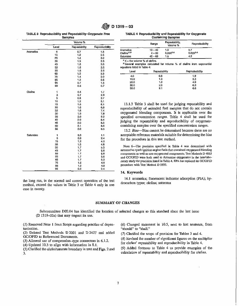
dOn., D 1319 - 03 "Illif1 TABLE 3 Reproducibility and Repeatability-Oxygenate Free
Samples
Volume 0/0
Level Rep eatability Reproducibility
Aromatics 5 0.7 1.5 15 1.2 2.5 25 lA 3.0 35 1.5 3.3 45 1.6 3.5 50 1.6 3.5 55 1.6 3.5 65 1.5 3.3 75 lA 3.0 85 1.2 2.5 95 0.7 1.5 99 0.3 0.7
Olefins 1 OA 1.7 3 n7 2.9 5 0.9 3.7
10 1.2 5.1 15 1.5 6.1 20 1.6 6.B 25 1.B 7A 30 1.9 7.8 35 2.0 B.2 40 2.0 BA 45 2.0 B.5 50 2.1 B.6 55 2.0 B.5
Saturates 1 0.3 1.1 5 O.B 2A
15 1.2 4.0 25 1.5 4.B 35 1.7 5.3 45 1.7 5.6 50 1.7 5 .• 55 1.7 5.6 65 1.7 5.3 75 1.5 4.8 B5 1.2 4.0 95 0.3 2A
the long run, in the normal and correct operation of the test method, exceed the values in Table 3 or Table 4 only in one case in twenty.
TABLE 4 Reproducibility and Repeatability for Oxygenate Containing Samples
Range Repeatability, Reproducibility Volume %
Aromatics 13-40 1.3 3.7 OlefinsA•B 4-33 0.26XD.6 0.82XD.6
Saturates 45-68 1.5 4.2
A X "" the volume % of olefins. B Several examples calculated for volume "10 of olefins from exponential
equations listed in Table 4: Level Repeatability Reproducibility
4.0 0.6 1.9 10.0 1.0 3.3 20.0 1.6 4.9 30.0 2.0 6.3 33.0 2.1 6.6
13.1.3 Table 3 sbull be used for judging repeatability and reproducibility of unleaded fuel samples that do not contain oxygenated blending components. It is applicable over the specified concentration ranges. Table 4 shall be used for judging the repeatability and reproducibility of oxygenatecontaining samples over the specified concentration ranges.
13.2 Bias-Bias cannot be determined because there are no acceptable reference materials suitable for determining the bias for the procedure in this test method.
NOTE 6-The precision specified in Table 4 was determined with automotive spark ignition engine fuels that contained oxygenated blending components as well as non-oxygenated components. Test Methods D 4815 and GC/OFID were both used to determine oxygenates in the interlaboratory study for precision listed in Table 4. EPA has replaced its GC/OFID procedure with Test Method D 5599.
14. Keywords
14.1 aromatics; fluorescent indicator adsorption (pIA); hydrocarbon types; olefins; saturates
SUMMARY OF CHANGES
Subcommittee D02.04 bus identified the location of selected changes to this standard since the last issue (D 1319-02a) that may impact its use.
(1) Removed Note 1 from Scope regarding practice of depentanization. (2) Deleted Test Methods D 2001 and D 2427 and added GCIOFID to Referenced Documents. (3) Allowed use of compression-type connectors in 6.1.2. (4) Updated 10.3 to align with information in 8.1. (5) Clarified the olefin/saturate boundary in text and Figs. 2 and 3.
7
(6) Changed statement in 10.5, next to last sentence, from "should" to "shall."
(7) Clarified the scope of precision for Tables 3 and 4. (8) Revised the number of significant figures on the multiplier for olefins' repeatability and reproducibility in Table 4. (9) Added footnote to Table 4 to provide examples of the calculation of repeatability and reproducibility for olefins.
001319-03
ASTM International takes no position respecting the validity of any patent rights Bsserted in connection with any item mentioned in this standard. Users of this standard are expressly advised that determination of the validity of any such patent rights, and the risk of infringement of such rights, are entirely their own responsibility.
This standard is subject to revision at any time by the responsible technioal committee and must be reviewed evel)' five years and if not revised, either reapproved or withdrawn. Your comments are invited either for revision of this standard or for additional standards and should be addressed to ASTM International Headquarters. Your comments wi(( receive careful consideration at a meeting of the responsible technical committee, which you may attend. If you feel that your comments have not received a fair hearing you should make your views known to the ASTM Committee on Standards, at the address shown below.
This standard is copyrighted by ASTM International, 100 Barr Harbor Drive, PO Box C700, West Conshohocken, PA 19428-2959, United States. Individual reprints (single or multiple copies) of this sta.ndard may be obtained by contacting ASTM at the above address or at 610-832-9585 (phone), 610-832-9555 (fax), or [email protected] (e-mail); or through the ASTM website (www.astm.org).
8


