Embed Size (px)
Citation preview
Assignment 3: Robot Design and Dynamics ME 328: Medical Robotics
Stanford University w Autumn 2016
Due to submission box outside Okamura’s office by 4:00 pm on Monday, October 24 (revised) Note: You can discuss this assignment with your classmates, but when you write/program your responses, you should be working by yourself. 1. Guest Speaker: Shane Farritor from University of Nebraska-Lincoln spoke about new approaches to general robotic surgery in which small robots are placed inside the body, in contrast to large robots that reach into the body. Write a short paragraph about the advantages and disadvantages of the small-robot approach. Please type your response. 2. Reading: You can download these papers from http://www.stanford.edu/class/me328/#readings Below are two book chapters from a 2011 edited book called “Surgical Robotics - Systems, Applications, and Visions” containing many interesting chapters, available at http://www.stanford.edu/class/me328/#resources. You will read a couple chapters about novel robot designs for minimally invasive surgery, as a contrast to the design of the da Vinci Surgical System. S. M. Farritor, A. C. Lehman, and D. Oleynikov. Miniature In Vivo Robots for Notes. In J. Rosen, B. Hannaford, and R. Satava, Eds., Surgical Robotics - Systems, Applications, and Visions, pp. 123-138. Springer, 2011. This chapter describes novel robots designed for Natural Orifice Translumenal Endoscopic Surgery (NOTES), a surgical approach in which natural orifices (e.g., the mouth) are used as the original entry point into the body, in order to avoid external incisions or scars. H. Choset, M. Zenati, T. Ota, A. Degani, D. Schwartzman. Enabling Medical Robotics for the Next Generation of Minimally Invasive Procedures: Minimally Invasive Cardiac Surgery with Single Port Access. In J. Rosen, B. Hannaford, and R. Satava, Eds., Surgical Robotics - Systems, Applications, and Visions, pp. 257-270. Springer, 2011. This chapter describes a novel, highly articulated robotic surgical system (CardioARM) for minimally invasive cardiac surgery. A. (Farritor et al.) What is the difference between NOTES and LESS? B. (Farritor et al.) Why is it useful to have robots designed only for visualization (and not manipulation)? C. (Farritor et al.) How is Farritor, et al.’s in vivo manipulator affixed to the abdominal wall? D. (Farritor et al.) What do you think are the advantages and drawbacks of the authors’ approach to
manipulation for NOTES? E. (Choset et al.) What are the main benefits of the CardioARM system for single port access? F. (Choset et al.) Explain the “shape-keeping” ability of the CardioARM.
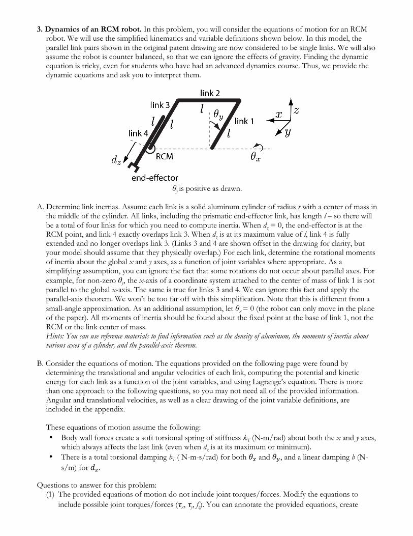
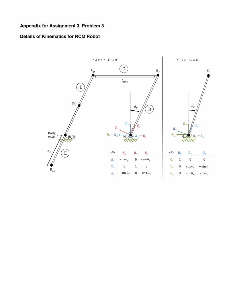
3. Dynamics of an RCM robot. In this problem, you will consider the equations of motion for an RCM robot. We will use the simplified kinematics and variable definitions shown below. In this model, the parallel link pairs shown in the original patent drawing are now considered to be single links. We will also assume the robot is counter balanced, so that we can ignore the effects of gravity. Finding the dynamic equation is tricky, even for students who have had an advanced dynamics course. Thus, we provide the dynamic equations and ask you to interpret them.
θy is positive as drawn.
A. Determine link inertias. Assume each link is a solid aluminum cylinder of radius r with a center of mass in
the middle of the cylinder. All links, including the prismatic end-effector link, has length l – so there will be a total of four links for which you need to compute inertia. When dz = 0, the end-effector is at the RCM point, and link 4 exactly overlaps link 3. When dz is at its maximum value of l, link 4 is fully extended and no longer overlaps link 3. (Links 3 and 4 are shown offset in the drawing for clarity, but your model should assume that they physically overlap.) For each link, determine the rotational moments of inertia about the global x and y axes, as a function of joint variables where appropriate. As a simplifying assumption, you can ignore the fact that some rotations do not occur about parallel axes. For example, for non-zero θy, the x-axis of a coordinate system attached to the center of mass of link 1 is not parallel to the global x-axis. The same is true for links 3 and 4. We can ignore this fact and apply the parallel-axis theorem. We won’t be too far off with this simplification. Note that this is different from a small-angle approximation. As an additional assumption, let θx = 0 (the robot can only move in the plane of the paper). All moments of inertia should be found about the fixed point at the base of link 1, not the RCM or the link center of mass. Hints: You can use reference materials to find information such as the density of aluminum, the moments of inertia about various axes of a cylinder, and the parallel-axis theorem.
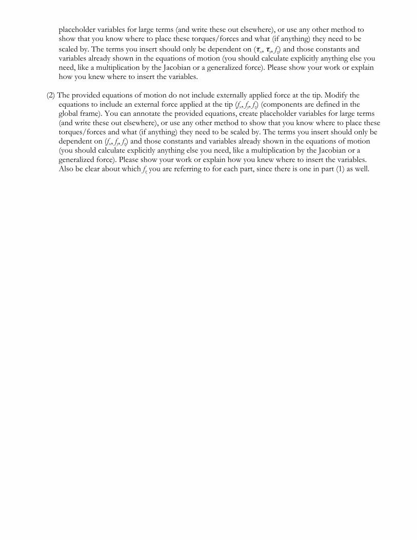
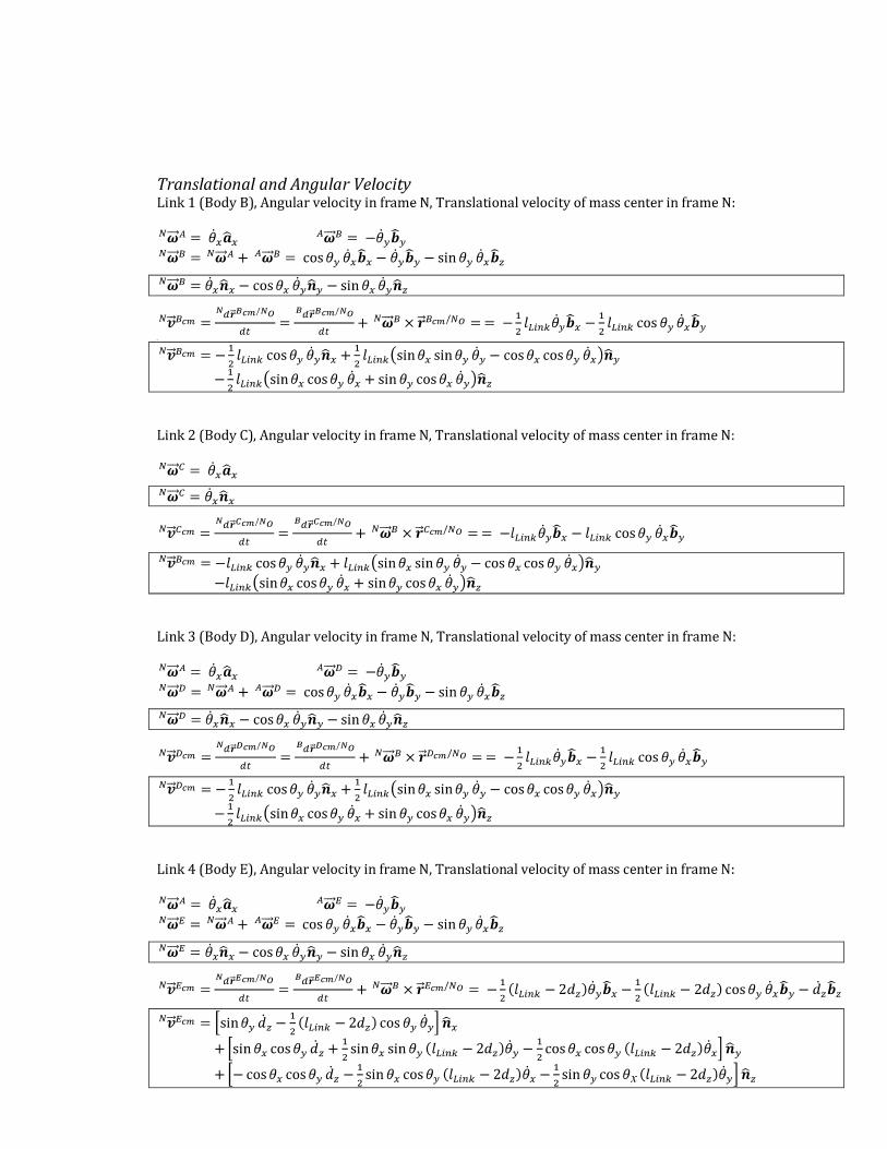
B. Consider the equations of motion. The equations provided on the following page were found by
determining the translational and angular velocities of each link, computing the potential and kinetic energy for each link as a function of the joint variables, and using Lagrange’s equation. There is more than one approach to the following questions, so you may not need all of the provided information. Angular and translational velocities, as well as a clear drawing of the joint variable definitions, are included in the appendix.
These equations of motion assume the following: • Body wall forces create a soft torsional spring of stiffness kT (N-m/rad) about both the x and y axes,
which always affects the last link (even when dz is at its maximum or minimum). • There is a total torsional damping bT ( N-m-s/rad) for both !! and !!, and a linear damping b (N-
s/m) for !!.
Questions to answer for this problem: (1) The provided equations of motion do not include joint torques/forces. Modify the equations to
include possible joint torques/forces (τx, τy, fz). You can annotate the provided equations, create
placeholder variables for large terms (and write these out elsewhere), or use any other method to show that you know where to place these torques/forces and what (if anything) they need to be scaled by. The terms you insert should only be dependent on (τx, τy, fz) and those constants and variables already shown in the equations of motion (you should calculate explicitly anything else you need, like a multiplication by the Jacobian or a generalized force). Please show your work or explain how you knew where to insert the variables.
(2) The provided equations of motion do not include externally applied force at the tip. Modify the equations to include an external force applied at the tip (fx, fy, fz) (components are defined in the global frame). You can annotate the provided equations, create placeholder variables for large terms (and write these out elsewhere), or use any other method to show that you know where to place these torques/forces and what (if anything) they need to be scaled by. The terms you insert should only be dependent on (fx, fy, fz) and those constants and variables already shown in the equations of motion (you should calculate explicitly anything else you need, like a multiplication by the Jacobian or a generalized force). Please show your work or explain how you knew where to insert the variables. Also be clear about which fz you are referring to for each part, since there is one in part (1) as well.
Equations of m
otion for the RC
M R
obot: !!=!!
−4! !!
!!" !!"#$ !!"#$!
4!!"#$!
+223!!"#$!
+(!!"#$ −
2!! ) !+sin !!! (3!!"#$
!−7!!"#$!
−(!!"#$ −
2!! ) !)
+!!
−4!!! +
3!2!!" !!"#$ !!"#$
!−7!2
!!" !!"#$!
!!"!"!
sin!! cos!! !! −!2 !!" !!"#$ !!"#$
!cos!! (!!"#$ −
2!! )(2cos!! !! +sin!! (!!"#$ −
2!! )!! )
!!" !!"#$ !!"#$!
4!!"#$!
+223!!"#$!
+(!!"#$ −
2!! ) !+sin !!! (3!!"#$
!−7!!"#$!
−(!!"#$ −
2!! ) !)
!!=!!
−4! !!
!!" !!"#$ !!"#$!
3!!"#$!
+7!!"#$!
+(!!"#$ −
2!! ) !
+!!
−4!!! −
!!!" !!"#$ !!"#$!
!!"#$ −2!!
!!−!!" !!"#$ !!"#$
!sin!! cos!!
3!!"#$!
−7!!"#$!
−(!!"#$ −
2!! ) !!! !
!!" !!"!" !!"#$!
3!!"#$!
+7!!"#$!
+(!!"#$ −
2!! ) !
!! =!! −
12 !!"#$!! !+
cos !!! !! !+!!
−!!!!" !!"#$ !!"#$
!
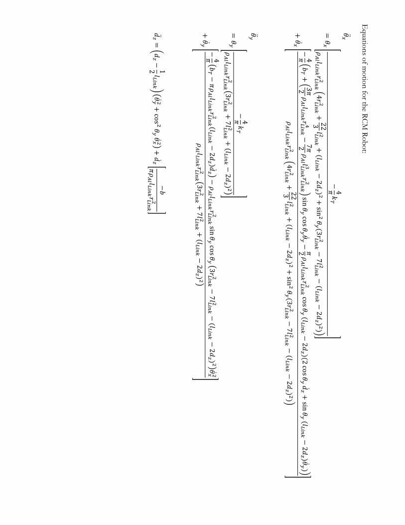
4. Simulating the effects of robot dynamics. Now that we have a model of the dynamics of this robot, let’s simulate its behavior in order to observe any control challenges.
Use the following values for the constants in this system: l = 0.5 m bT = 0.01 N-m-s/rad kT = 1 N-m/rad r = 3 cm b = 0.01 N-s/m material of links: Aluminum
A. Simulate the homogeneous response of this system, starting from a static offset of !! = 30o, !! = 30o, and !! = 0.25 m. Use a Matlab ODE solver, the ‘ode45’ function. Capture the behavior of the robot in movie frames as did in Assignment 1 (re-use your code from Assignment 1; you can show extra parallel links not included in the dynamic model), and create a movie of the response. Save the movie with the following command: save('JohnDoeAssignment3MovieA','MyMovieWorkspaceName') and send it along with your accompanying code (JohnDoeAssignment3CodeA.m) to [email protected].
B. Say the RCM robot is being teleoperated, such that the desired end-effector movement commanded by
the user is to trace a horizontal circle of radius 20 cm, which is centered at a distance of 20 cm directly below the RCM point, at a frequency of 1 revolution around the circle per second. To achieve this motion, a PD controller is employed, where the desired position and velocity are based on the circle-following trajectory and the actual position and velocity are that of the robot end-effector. Select gains for the PD controller to achieve satisfactory behavior and simulate the system with the commanded trajectory and PD controller in effect. Create a movie of the manipulator behavior for several revolutions of the circle. Your graphics should include the circle to be traced. Save the movie using: save('JohnDoeAssignment3MovieB','MyMovieWorkspaceName') and send it with your accompanying code ('JohnDoeAssignment3CodeB.m') to [email protected]. In addition, submit two hardcopy Matlab plots: (1) show on a single plot the three actuator torques/forces versus time for the same several revolutions as in the video, and (2) show on a single plot the difference between the desired and actual end-effector positions versus time in the x, y, and z directions.
C. Repeat part B, except with the circle now raised so that the distance below the RCM point is 10 cm. End
your filenames with ‘C’ instead of ‘B’, and submit the plots. Use the same PD controller gains from part B. Comment on the reason for any differences you see. How could you improve performance?
D. Return to the case of tracking a circle as in part B. If you provided position-based haptic feedback to the
master, how much force would the user feel if the circle-tracking motion was done in free space? E. Say that a surgeon aims to use the RCM robot from part B to palpate liver tissue to determine the extent
of a tumor. Palpation is accomplished by pushing on the tissue in order to determine its linear stiffness – k in F = kx. According to Masuzaki et al. (http://www.ncbi.nlm.nih.gov/pmc/articles/PMC2716830/), normal liver tissue has a Young’s modulus of about 5 kPa and cancerous tumors have a larger modulus of about 55 kPa.1 Humans’ just noticeable difference (JND) for force perception is about 10%. The JND is the smallest amount by which a stimulus (e.g., force) must change in order to be detected, divided by the original level of the stimulus. Use dynamic simulations and calculations to determine the situations in which a position-based haptic feedback teleoperator would and would not enable a human operator to distinguish between healthy and cancerous liver tissue. How would various system parameters (i.e., dynamic parameters) and aspects of human motion (i.e., speed of palpation, direction of palpation) affect a user’s ability to discriminate?
1 Masuzaki et al. call this “stiffness”, but it is actually Young’s modulus. For an element in compression, the relationship between stiffness and Young’s modulus is k = AE/L, where A is the cross-sectional area, E is the Young’s modulus, and L is the length of the element being compressed. You can assume a value of A/L of 0.04 m.
-
Appendix for Assignment 3, Problem 3
Details of Kinematics for RCM Robot
x


![Decentralized Allocation of Tasks with Temporal and ...gini/publications/papers/...the XD [ST-SR-TA = Single-Task robot, Single-Robot task, Time-extended Assignment] category in the](https://img.pdfslide.us/doc/110x75/60c7ac7d7aa5b34da2488c9f/decentralized-allocation-of-tasks-with-temporal-and-ginipublicationspapers.jpg)