Embed Size (px)
Citation preview

Asset Geotechnical Engineering Pty Ltd ABN 24 093 381 107
Email & Web
[email protected] www.assetgeotechnical.com.au
Sydney
Suite 2.05 / 56 Delhi Road North Ryde NSW 2113
Phone: 02 9878 6005 Fax: 02 8282 5011
2353-R1 7 May 2014 Ku-ring-Gai Council Locked Bag 1056 Pymble NSW 2073 Attention: Mr Noa Tranter Dear Sir, PROPOSED CAR PARK, 8-10 TRYON ROAD, LINDFIELD GEOTECHNICAL INVESTIGATION
1. INTRODUCTION
1.1 General
This report presents the results of a geotechnical investigation for the above project. The investigation was commissioned on 13 February 2014 by Mr Noa Tranter of Ku-ring-Gai Council. The work was carried out in accordance with a proposal by Asset Geotechnical Engineering Pty Ltd dated 9 February 2014, reference P2856.
It is understood that the project involves construction of a one or two level basement car park with a new village green urban park and small amenities and café building constructed over. No architectural design was available by the time of the investigation, and we have therefore considered the implications of both a one and two level basement.
The objective of the investigation is to provide information on surface and subsurface conditions for design of the proposed structures.
1.2 Scope of Work
The main objectives of the investigation were to assess the surface and subsurface conditions and to provide comments and recommendations relating to: • Excavation conditions, methodology and monitoring • Shoring and excavation support, including an assessment of potential construction problems (if any) • Protection measures for adjacent developments • Dewatering • Subsoil drainage • Subgrade preparation and earthworks • Site Classification to AS2870-2011 ‘Residential Slabs and Footings’ • Suitable foundations • Allowable bearing pressure
In order to achieve the project objectives, the following scope of work was carried out: • Review of available reports and maps held within our files. • Search for buried metallic services and utilities within the site boundaries for the purposes of the field
investigation.
2
PROPOSED CAR PARK, 8-10 TRYON ROAD, LINDFIELD 2353-R1 GEOTECHNICAL INVESTIGATION 7 MAY 2014
• Walkover observations of site conditions. • Drilling and logging of 4 non-core boreholes and one cored borehole to sample and assess the nature
and consistency of subsurface soils and bedrock. • The recovered rock core was photographed and logged. • Obtain licence from NSW Office of Water and install 2 piezometers for measurement of the
groundwater level. • Engineering assessment and reporting.
This report should be read in conjunction with the attached Information Sheets. Particular attention is drawn to the limitations inherent in site investigations and the importance of verifying the subsurface conditions inferred herein.
2. FIELDWORK
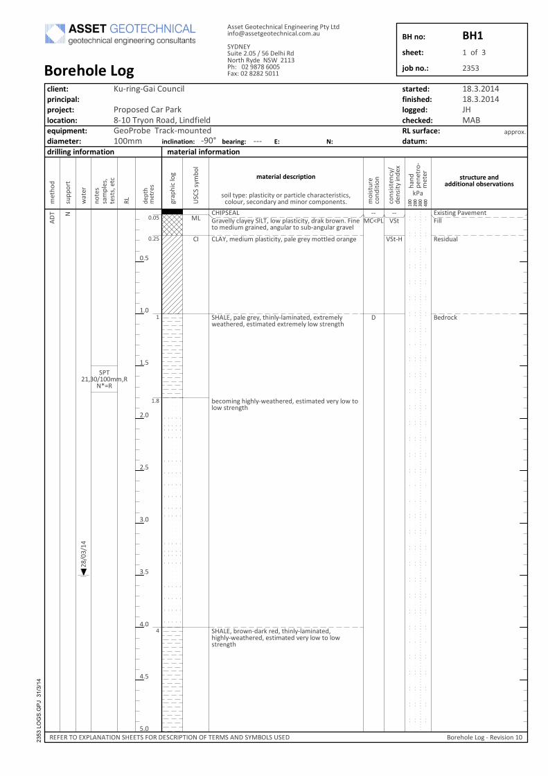
The investigation was carried out on 18th March 2013 using a track-mounted drilling rig, and included drilling 4 non-core boreholes (BH1 to BH4) to the depths from 2.4m to 10.5m and one cored borehole (BH5) to refusal on rock at 4.45m depth and continued by NMLC coring to 7.6m, and installation of 2 piezometers (at BH1 and BH5). The test locations are shown on the attached Figure 2.
On completion of logging and sampling, two 50mm diameter PVC standpipe piezometer were installed in the boreholes BH1 and BH5 to the recorded refusal depths. The piezometer construction comprised machine slotted screening section of the bottom 3m, then backfilling the annulus with clean sands 1m above the screen and then a 0.5m thick bentonite plug on top of the sand to prevent surface water directly entering the piezometer. The hole above the bentonite was backfilled with spoil from the drilling, and a cast-iron road box concreted flush with the adjacent ground surface. Boreholes BH2 to BH4 were backfilled directly with the drilling spoil. The recovered rock core was logged and photographed.
The borehole locations were set out by our engineer from existing site features and site access. The subsurface conditions encountered were recorded during the progress of the drilling. No survey data available by the time of the investigation, therefore, surface levels at the test locations were not determined.
Engineering logs and explanatory notes are attached to this report.
3. SITE DESCRIPTION
The site is located at the western side of Tryon Road in Lindfield, near the intersection of Tryon Road and Lindfield Avenue, as shown in Figure 1. The site is “L”-shaped and is bounded by Tryon Road to the south, Chapman Lane to the west, Kochia Lane to the north and a 2-storey commercial building to the east. It is currently an at-grade car park.
Topographically, the site is situated on a east-west trending ridgeline within gently undulating terrain. Locally, the ground surface slopes down to the northeast at between about 4º to 6º.
Existing site development surrounding the existing at-grade car park includes 2 to 3-storey commercial and community service buildings to the west, north and east, together with a 5-storey apartment block located to the north-east.
Vegetation comprises a few sparsely scattered, mature trees across the car park.
3
PROPOSED CAR PARK, 8-10 TRYON ROAD, LINDFIELD 2353-R1 GEOTECHNICAL INVESTIGATION 7 MAY 2014
4. SUBSURFACE CONDITIONS
4.1 Geology
The 1:100,000 Sydney Geological Map indicates the site is underlain by Ashfield Shale. These rocks typically weather to form residual clays soils of medium plasticity.
The 1:100,000 Sydney Soil Landscape Map shows that the site is within the Glenorie soil group. These soils are with high soil erosion hazard, localised impermeable highly plastic subsoil and moderately reactive.
4.2 Stratigraphy
A summary description is provided in Table 1 for the conditions observed at the test locations for this investigation. The detailed conditions at each test location are recorded on the attached logs. For specific design input, reference should be made to the logs and/or the specific test results, in lieu of the description in Table 1.
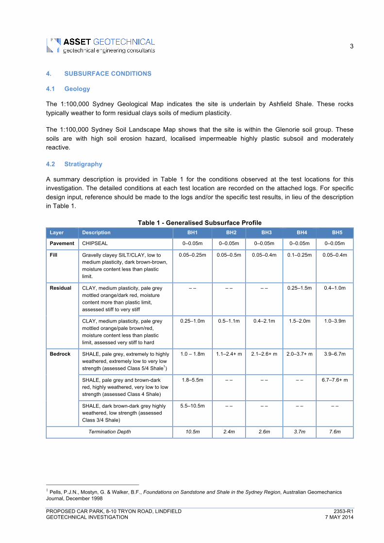
Table 1 - Generalised Subsurface Profile Layer Description BH1 BH2 BH3 BH4 BH5
Pavement CHIPSEAL 0–0.05m 0–0.05m 0–0.05m 0–0.05m 0–0.05m
Fill Gravelly clayey SILT/CLAY, low to medium plasticity, dark brown-brown, moisture content less than plastic limit.
0.05–0.25m 0.05–0.5m 0.05–0.4m 0.1–0.25m 0.05–0.4m
Residual CLAY, medium plasticity, pale grey mottled orange/dark red, moisture content more than plastic limit, assessed stiff to very stiff
– – – – – – 0.25–1.5m 0.4–1.0m
CLAY, medium plasticity, pale grey mottled orange/pale brown/red, moisture content less than plastic limit, assessed very stiff to hard
0.25–1.0m 0.5–1.1m 0.4–2.1m 1.5–2.0m 1.0–3.9m
Bedrock SHALE, pale grey, extremely to highly weathered, extremely low to very low strength (assessed Class 5/4 Shale1)
1.0 – 1.8m 1.1–2.4+ m 2.1–2.6+ m 2.0–3.7+ m 3.9–6.7m
SHALE, pale grey and brown-dark red, highly weathered, very low to low strength (assessed Class 4 Shale)
1.8–5.5m – – – – – – 6.7–7.6+ m
SHALE, dark brown-dark grey highly weathered, low strength (assessed Class 3/4 Shale)
5.5–10.5m – – – – – – – –
Termination Depth 10.5m 2.4m 2.6m 3.7m 7.6m
1 Pells, P.J.N., Mostyn, G. & Walker, B.F., Foundations on Sandstone and Shale in the Sydney Region, Australian Geomechanics Journal, December 1998
4
PROPOSED CAR PARK, 8-10 TRYON ROAD, LINDFIELD 2353-R1 GEOTECHNICAL INVESTIGATION 7 MAY 2014
4.3 Groundwater
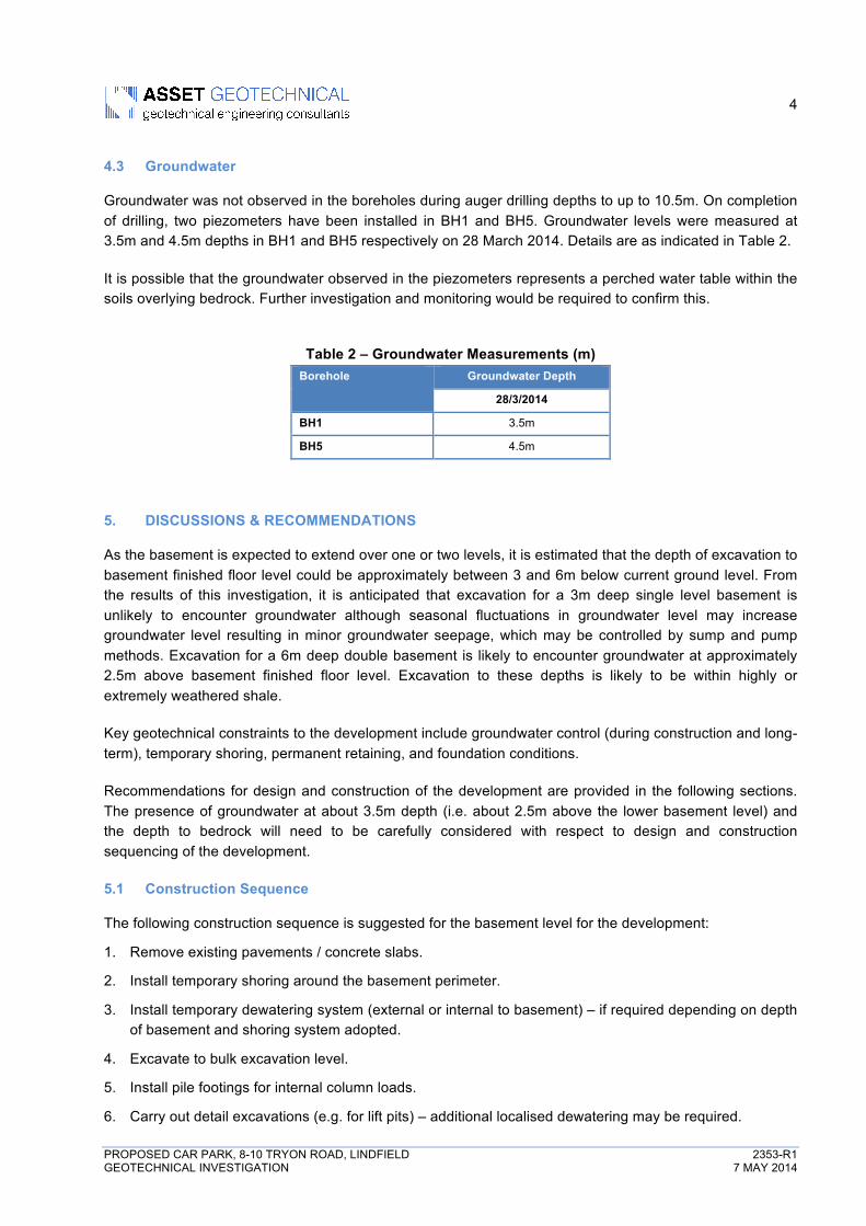
Groundwater was not observed in the boreholes during auger drilling depths to up to 10.5m. On completion of drilling, two piezometers have been installed in BH1 and BH5. Groundwater levels were measured at 3.5m and 4.5m depths in BH1 and BH5 respectively on 28 March 2014. Details are as indicated in Table 2.
It is possible that the groundwater observed in the piezometers represents a perched water table within the soils overlying bedrock. Further investigation and monitoring would be required to confirm this.
Table 2 – Groundwater Measurements (m) Borehole Groundwater Depth
28/3/2014
BH1 3.5m
BH5 4.5m
5. DISCUSSIONS & RECOMMENDATIONS
As the basement is expected to extend over one or two levels, it is estimated that the depth of excavation to basement finished floor level could be approximately between 3 and 6m below current ground level. From the results of this investigation, it is anticipated that excavation for a 3m deep single level basement is unlikely to encounter groundwater although seasonal fluctuations in groundwater level may increase groundwater level resulting in minor groundwater seepage, which may be controlled by sump and pump methods. Excavation for a 6m deep double basement is likely to encounter groundwater at approximately 2.5m above basement finished floor level. Excavation to these depths is likely to be within highly or extremely weathered shale.
Key geotechnical constraints to the development include groundwater control (during construction and long-term), temporary shoring, permanent retaining, and foundation conditions.
Recommendations for design and construction of the development are provided in the following sections. The presence of groundwater at about 3.5m depth (i.e. about 2.5m above the lower basement level) and the depth to bedrock will need to be carefully considered with respect to design and construction sequencing of the development.
5.1 Construction Sequence
The following construction sequence is suggested for the basement level for the development:
1. Remove existing pavements / concrete slabs.
2. Install temporary shoring around the basement perimeter.
3. Install temporary dewatering system (external or internal to basement) – if required depending on depth of basement and shoring system adopted.
4. Excavate to bulk excavation level.
5. Install pile footings for internal column loads.
6. Carry out detail excavations (e.g. for lift pits) – additional localised dewatering may be required.
5
PROPOSED CAR PARK, 8-10 TRYON ROAD, LINDFIELD 2353-R1 GEOTECHNICAL INVESTIGATION 7 MAY 2014
7. Construct lower basement ground floor.
8. Pour lower basement roof and continue up to existing ground surface level to provide permanent support to the excavation.
9. Decommission temporary dewatering system.
5.2 Temporary Shoring and Permanent Retaining Walls
It is understood that permanent batter slopes are not proposed for the development. The proposed depth of excavation, the presence of groundwater, and the potential lack of clearance between the basement and boundary would preclude temporary batters, and therefore temporary shoring will be required. Depending on the design of the shoring, it could also be incorporated into the permanent foundation and retaining works.
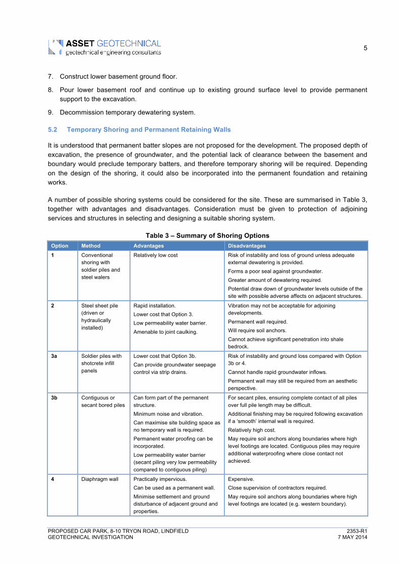
A number of possible shoring systems could be considered for the site. These are summarised in Table 3, together with advantages and disadvantages. Consideration must be given to protection of adjoining services and structures in selecting and designing a suitable shoring system.
Table 3 – Summary of Shoring Options Option Method Advantages Disadvantages
1 Conventional shoring with soldier piles and steel walers
Relatively low cost Risk of instability and loss of ground unless adequate external dewatering is provided.
Forms a poor seal against groundwater.
Greater amount of dewatering required. Potential draw down of groundwater levels outside of the site with possible adverse affects on adjacent structures.
2 Steel sheet pile (driven or hydraulically installed)
Rapid installation. Lower cost that Option 3. Low permeability water barrier.
Amenable to joint caulking.
Vibration may not be acceptable for adjoining developments.
Permanent wall required. Will require soil anchors.
Cannot achieve significant penetration into shale bedrock.
3a Soldier piles with shotcrete infill panels
Lower cost that Option 3b. Can provide groundwater seepage control via strip drains.
Risk of instability and ground loss compared with Option 3b or 4.
Cannot handle rapid groundwater inflows.
Permanent wall may still be required from an aesthetic perspective.
3b Contiguous or secant bored piles
Can form part of the permanent structure.
Minimum noise and vibration. Can maximise site building space as no temporary wall is required.
Permanent water proofing can be incorporated.
Low permeability water barrier (secant piling very low permeability compared to contiguous piling)
For secant piles, ensuring complete contact of all piles over full pile length may be difficult.
Additional finishing may be required following excavation if a ‘smooth’ internal wall is required.
Relatively high cost. May require soil anchors along boundaries where high level footings are located. Contiguous piles may require additional waterproofing where close contact not achieved.
4 Diaphragm wall Practically impervious. Can be used as a permanent wall.
Minimise settlement and ground disturbance of adjacent ground and properties.
Expensive. Close supervision of contractors required.
May require soil anchors along boundaries where high level footings are located (e.g. western boundary).
6
PROPOSED CAR PARK, 8-10 TRYON ROAD, LINDFIELD 2353-R1 GEOTECHNICAL INVESTIGATION 7 MAY 2014
5.2.1 Two Level Basement
Based on the advantages and disadvantages listed in Table 3 above, we recommend that for a double level basement, Option 3a or Option 3b would likely be suitable shoring systems. We consider the geotechnical risks associated with Option 1 (predominantly groundwater control and excavation support) to be unacceptably high. Option 2 is not likely to be suitable due to the depth of excavation support and adjacent structures. Option 4 may be too expensive for the scale of the project however should still be considered.
The founding depth of the retaining wall piles is a function of the required socket depth to achieve adequate embedment to resist overturning, the required load carrying capacity if the piles are to be incorporated into the permanent works, and the effect on reducing dewatering requirements by socketing into bedrock.
Retaining walls founded on assessed Class 5 shale may be designed for a maximum allowable end bearing pressure of 700kPa and a maximum allowable shaft adhesion of 50kPa. Depending on the retained height and the sensitivity of adjacent structures to lateral movement, it may be necessary to provide ground anchors to provide further resistance against lateral earth pressures and control horizontal movement. Further advice should be sought once the pile loads and layout are known.
5.2.2 Single Level Basement
For a single level basement, we recommend Option 3a as a suitable option. A suitable depth of embedment will be required to resist the lateral pressures on the wall. Assessed Class 5 Shale bedrock is likely to provide adequate overturning resistance for the socketed piles.
For a retained height of up to 2.5m, it is anticipated that a cantilever wall arrangement would be considered acceptable. However, control of lateral deflections will also need to be considered (e.g. for adjacent movement sensitive structures and/or significant surcharge loads), where temporary rock anchors may be required.
5.2.3 Design Approach
It is assumed that the retaining walls will have permanent lateral restraint provided by the basement floor levels and ground floor slabs, and may be designed as braced retaining walls. The temporary shoring should be designed as a cantilever retaining wall.
Cantilever walls may be designed for a triangular earth pressure distribution using a lateral earth pressure coefficient (Ka) for the soil and Class 5/4 Shale of 0.5 where it is desired to minimise deflections (e.g. where adjacent to existing structures or movement-sensitive buried services), and 0.3 elsewhere. Rock anchors should also be considered where it is required to minimise lateral deflection of temporary shoring (e.g. where adjacent to high level footings or buried services adjoining the site).
Braced retaining walls may be designed for a uniform lateral earth pressure of 0.65 * γ * H * Ka where γ = unit weight of retained soil (say 18kN/m3), H = height of wall, and Ka = earth pressure coefficient (0.5 or 0.3 as noted above).
For assessment of passive restraint embedded below excavation level we recommend a triangular pressure distribution with a coefficient of passive pressure (Kp) of 2.0 for the very stiff to hard clay, and 3.0 for the assessed Class 5/4 Shale. This includes a reduction factor to the ultimate value of Kp to take into account strain incompatibility between active and passive pressure conditions.
7
PROPOSED CAR PARK, 8-10 TRYON ROAD, LINDFIELD 2353-R1 GEOTECHNICAL INVESTIGATION 7 MAY 2014
Appropriate surcharge loading at the finished surface level should also be adopted for design of the wall. A fully waterproof basement should be adopted, and should be designed to withstand hydrostatic pressures. In the absence of long-term monitoring of groundwater levels to establish an appropriate design water level, it is suggested that a nominal groundwater level of 2.5m depth below ground level be considered.
Detailed construction supervision, monitoring and inspections will be required during the piling and subsequent bulk excavation to ensure and adequate standard of workmanship and to minimise potential problems.
5.3 Groundwater Control
In order to construct the basement, it will be necessary to control groundwater inflow. The method of groundwater control will depend heavily on the nature of the groundwater (i.e. perched water table within the soils overlying bedrock, or a continuous unconfined aquifer extending through the soil profile and into the bedrock beneath), and also on mass permeability as well as the presence of local, high-permeability zones.
Temporary lowering of the groundwater level can cause settlement of the soil profile due to a change in the stress regime. The magnitude of settlement depends on the soil type and condition, draw down depth and duration, and historical water levels. The nature of the geological/hydrogeological environment at the site is such that groundwater lowering is unlikely to induce significant settlements particularly for a single level basement where any groundwater lowering is likely to be relatively minor. Where significant groundwater lowering is required such as for a double basement where groundwater may be 2 to 3m above basement floor level, consideration should be given to the effect on adjacent structures of the consequential increase in effective stress caused by the dewatering.
5.3.1 Double Level Basement
For a double basement, Option 3b (contiguous or secant piles to bedrock) together with internal dewatering would provide adequate control of groundwater for construction purposes. The development should be designed to minimise the risk of settlement induced by groundwater lowering by designing the basement structure as a "tanked" excavation (i.e. with impermeable retaining walls and floor structure). Permanent dewatering is not recommended.
If Option 3a is adopted (soldier piles and shotcrete infill panels), temporary groundwater control during construction could be achieved by the incorporation of strip drains behind shotcrete panels which progressively carry collected drainage water down to the base of the excavation and into a sump and pump system.
The quantity of seepage expected to flow into the excavation during construction is unknown. It will depend on the in-situ permeability of the residual clay and extremely weathered shale bedrock, the flow path length, and the type and adequacy of construction of the temporary shoring adopted (e.g. contiguous versus secant piling). The influence of jointing / fracturing on groundwater seepage is considered to be negligible in the extremely weathered shale although it could have some influence in the highly weathered shale. At this stage no in-situ or laboratory permeability tests of the site subsurface profile has been undertaken. However, based on the borehole soil description of the residual clays and with reference to empirical charts, we anticipate that the permeability of the residual clays would be in the order of 10-6 to 10-8 cm/sec. The mass permeability of the underlying shale bedrock could be of a similar order to the lower end of the scale (10-8 cm/s) for the residual clay.
8
PROPOSED CAR PARK, 8-10 TRYON ROAD, LINDFIELD 2353-R1 GEOTECHNICAL INVESTIGATION 7 MAY 2014
Depending on seepage flows/water levels at the time of construction and the type of retention system constructed, we expect that dewatering by internal spear points may be required to permit excavation works as conventional sump and pump methods are likely to be inadequate unless piezometer levels at the time of construction indicate groundwater to be lower than anticipated. Piezometers external to the basement excavation and near the site boundaries should be provided to monitor groundwater levels during dewatering. Only experienced dewatering subcontractors with appropriate monitoring systems should be considered. We recommend further involvement of an experienced geotechnical engineer and hydrogeologist during the design, construction and operation / monitoring of groundwater control systems.
5.3.2 Single Level Basement
For a single level basement constructed with soldier piles and shotcrete infill panels, temporary groundwater control during construction could be achieved by the incorporation of strip drains behind shotcrete panels which progressively carry collected drainage water down to the base of the excavation and into a sump and pump system.
5.4 Earthworks
5.4.1 Excavation
The excavation for the proposed development will be through existing fill and natural clayey soils and then through extremely to highly weathered shale bedrock. It is anticipated that the residual soils could be readily excavated using conventional earthmoving equipment (e.g. hydraulic excavator bucket). The assessed Class 5/4 shale bedrock could also likely be readily excavated using similar equipment possibly supplemented by a ripping tooth, but at a slower rate. For a double level basement, the base of the excavation may encounter low strength Class 3/4 shale bedrock which is expected to require the use of rock-breaking equipment.
The rock is likely to be continuous across adjoining properties. Excavation requirements will be governed by the strength of the rock encountered, the sensitivity of adjacent buildings and the presence of services, to vibrations caused by the rock excavation. Close controls by the excavation contractor over the rock excavation are necessary so that excessive vibration effects are not generated.
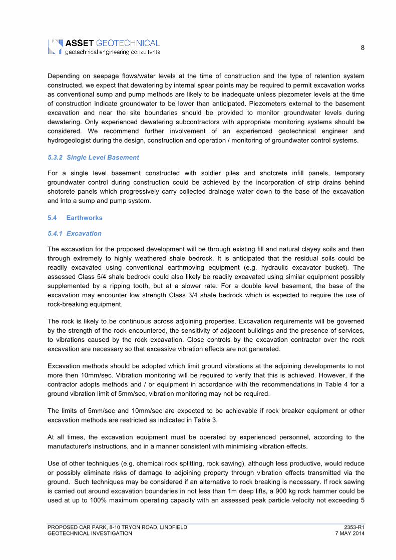
Excavation methods should be adopted which limit ground vibrations at the adjoining developments to not more then 10mm/sec. Vibration monitoring will be required to verify that this is achieved. However, if the contractor adopts methods and / or equipment in accordance with the recommendations in Table 4 for a ground vibration limit of 5mm/sec, vibration monitoring may not be required.
The limits of 5mm/sec and 10mm/sec are expected to be achievable if rock breaker equipment or other excavation methods are restricted as indicated in Table 3.
At all times, the excavation equipment must be operated by experienced personnel, according to the manufacturer's instructions, and in a manner consistent with minimising vibration effects.
Use of other techniques (e.g. chemical rock splitting, rock sawing), although less productive, would reduce or possibly eliminate risks of damage to adjoining property through vibration effects transmitted via the ground. Such techniques may be considered if an alternative to rock breaking is necessary. If rock sawing is carried out around excavation boundaries in not less than 1m deep lifts, a 900 kg rock hammer could be used at up to 100% maximum operating capacity with an assessed peak particle velocity not exceeding 5
9
PROPOSED CAR PARK, 8-10 TRYON ROAD, LINDFIELD 2353-R1 GEOTECHNICAL INVESTIGATION 7 MAY 2014
mm/sec, subject to observation and confirmation by a geotechnical engineer at the commencement of excavation.
It should be noted that vibrations that are below threshold levels for building damage might be experienced at adjoining developments.
Table 3 - Recommendations for Rock Breaking Equipment Distance from adjoining structure (m)
Maximum Peak Particle Velocity 5mm/sec Maximum Peak Particle Velocity 10mm/sec*
Equipment Operating Limit (% of Maximum Capacity)
Equipment Operating Limit (% of Maximum Capacity)
1.5 to 2.5 Hand operated jackhammer only
100 300 kg rock hammer 50
2.5 to 5.0 300 kg rock hammer 50 300 kg rock hammer
or 600 kg rock hammer
100
50
5.0 to 10.0 300 kg rock hammer 100 600 kg rock hammer 100
or or
600 kg rock hammer 50 900 kg rock hammer 50
* Vibration monitoring is recommended for 10mm/sec vibration limit.
5.4.2 Subgrade Preparation
The following general recommendations are provided for subgrade preparation for earthworks, pavements, and slab-on-ground construction, and minor structures: • Strip existing fill and topsoil. Remove unsuitable materials from site (e.g. material containing deleterious
matter). Stockpile remainder for re-use as landscaping material or remove from site. • Excavate residual clayey soils and rock, stockpiling for re-use as engineered fill or remove to spoil.
Rock could be stockpiled separately from clayey soils, for select use beneath pavements. • Where rock is exposed in bulk excavation level beneath pavements, rip a further 150mm. • Where rock is exposed at footing invert level, it should be free of loose and softened material, before
concrete is poured. • Compact the upper 150mm depth to a dry density ratio (AS1289.5.4.1–2007) not less than 100%
Standard. Areas which show visible heave under compaction equipment should be over-excavated a further 0.3m and replaced with approved fill compacted to a dry density ratio not less than 100%.
Further advice should be sought where the depth of filling beneath pavements and/or structures exceeds that noted above, or where filling is required to support major structures.
Any waste soils being removed from the site must be classified in accordance with current regulatory authority requirements to enable appropriate disposal to an appropriately licensed landfill facility. Further advice should be sought from a specialist environmental consultant if required.
5.4.3 Filling
Where filing is required, place in horizontal layers not more than 0.3m loose thickness over prepared subgrade and compact to a dry density ratio not less than 95% Standard beneath pavements and 98% Standard beneath structures. The moisture content during compaction should be maintained at ±2% of
10
PROPOSED CAR PARK, 8-10 TRYON ROAD, LINDFIELD 2353-R1 GEOTECHNICAL INVESTIGATION 7 MAY 2014
Standard Optimum. Compact the upper 150mm of subgrade to a dry density ratio not less than 100% Standard.
Filling within 1.5m of the rear of retaining walls should be compacted using lightweight equipment (e.g. hand-operated plate compactor or ride-on compactor not more than 3 tonnes static weight) in order to limit compaction-induced lateral pressures. The layer thickness should be reduced to 0.2m maximum loose thickness.
Any soils to be imported onto the site for the purpose of back-filling and re-instatement of excavated areas should be free of contamination and deleterious material, and should include appropriate validation documentation in accordance with current regulatory authority requirements which confirms its suitability for the proposed land use. Further advice should be sought from a specialist environmental consultant if required.
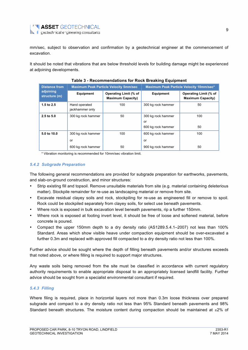
5.4.4 Batter Slopes
Recommended maximum slopes for temporary batters are presented in Table 4 following.
Table 4 - Recommended Maximum Batter Slopes Unit Maximum Batter Slope (H : V)
Permanent Temporary
Fill and Residual Clay 2 : 1 1 : 1
Class 5/4 Shale 1.5 : 1 0.75 : 1
Class 4 Shale or better vertical * vertical *
* subject to inspection by a geotechnical engineer and carrying out remedial works as recommended (e.g. shotcrete, rock bolting).
5.5 Lot Classification
The following recommendations for Lot Classification are provided for ancillary, light commercial structures not directly connected to the basement carpark and founded within the soils overlying rock.
The subsurface investigations described above indicate that filling (gravelly clay/silt) is generally present up to a depth of 0.5m. It is assessed that the fill would not meet the requirements for “controlled” fill as defined in AS2870-2011 “Residential Slabs and Footings”. Therefore, in its current condition, the site is classified as a “Class P” in accordance with AS2870-2011.
Footing design should be carried out in accordance with the recommendations in Section 5.6.2.
The above lot classification and the following footing recommendations are provided on the basis that the performance expectations set out in Appendix B of AS2870–2011 are acceptable and that future site maintenance is in accordance with CSIRO BTF 18, a copy of which is attached.
An experienced geotechnical engineer should review footing designs to check that the recommendations of the geotechnical report have been included, and should assess footing excavations to confirm the design assumptions.
5.6 Footings
Footings may be designed and constructed in accordance with the following recommendations.
11
PROPOSED CAR PARK, 8-10 TRYON ROAD, LINDFIELD 2353-R1 GEOTECHNICAL INVESTIGATION 7 MAY 2014
An experienced geotechnical engineer should review footing designs to check that the recommendations of the geotechnical report have been included, and should assess footing excavations to confirm the design assumptions.
5.6.1 Basement Structures
Suitable footings are likely to comprise a slab on ground for the basement area and shallow strip or pad footings supporting internal columns or any higher level building loads located outside the basement footprint.
Strip and Pad Foundations
Pad and strip footings supporting internal columns should be founded on the bedrock at basement level. Foundations constructed on the Class 5/4 shale may be designed for a maximum allowable bearing pressure of 700kPa. Higher allowable bearing pressures of up to 1.0MPa may be attained by constructing on the Class 3/4 shale.
All strip and pad foundations should be constructed on similar strength soil/rock. Where this is not possible, construction joints should be considered to accommodate differential settlements that may occur as a result of this.
If there are significant soft layers beneath a footing, the softer material will have to be excavated and replaced with either compacted hardfill or 10MPa concrete. With hardfill, the sub-excavation will have to have plan dimensions of B+D where B is the footing width and D is the depth of undercut. With concrete, the sub-excavation can have the same dimensions as the footing.
An experienced geotechnical engineer should review footing designs to check that the recommendations of the geotechnical report have been included, and should assess footing excavations to confirm the design assumptions.
Basement Slabs
Single level Basement
Basement slabs are likely to be founded on extremely or highly weathered Class 5/4 or 4 shale. Residual clay soil may also be exposed in some areas of the excavation. Extremely to highly weathered shale is estimated to have an allowable bearing pressure of approximately 0.7MPa. This increases to 1.0MPa for highly weathered (class 4) shale.
Groundwater levels measured in the two piezometers indicate groundwater is expected to be below basement level. However seasonal fluctuations can cause groundwater levels to rise. Basement floors should be therefore designed to accommodate some nominal hydrostatic uplift. Tanking of the basement should also be provided and should continue up basement walls to a depth of 1 to 2m below ground level.
Slab design should also incorporate connecting dowels or shear keys at construction or expansion joints between adjoining slabs to minimise differential settlements between slab panels.
12
PROPOSED CAR PARK, 8-10 TRYON ROAD, LINDFIELD 2353-R1 GEOTECHNICAL INVESTIGATION 7 MAY 2014
Double Basement
Basement slabs are likely to be founded on extremely to highly weathered or highly weathered Class 4 or 3/4 shale. Allowable bearing pressures for the highly weathered shale are estimated to be 1.5MPa. Extremely to highly weathered shale is estimated to have an allowable bearing pressure of approximately 1.0MPa.
Groundwater levels are expected to be approximately 2 to 3m (or more) above basement floor level. Basement floor slabs should be therefore designed to accommodate some nominal hydrostatic uplift. Tanking of the basement should also be provided and should continue up basement walls to a depth of 1 to 2m below ground level.
Slab design should also incorporate connecting dowels or shear keys at construction or expansion joints between adjoining slabs to minimise differential settlements between slab panels.
Where basement slabs are constructed below groundwater depths as indicated in this report and the basement is designed as a tanked structure, uplift pressures should also be considered.
5.6.2 Ancillary Structures
Ancillary, light commercial structures located outside the ‘zone of influence’ of the basement car park may be supported on strip or pad footings or on a stiffened raft slab, founded within the very stiff or better residual clay, and designed and constructed in accordance with the recommendations and advice in AS2870-2011 for a Class H (highly reactive) site. The ‘zone of influence’ is defined as a line extending upwards and outwards at 45º above horizontal from the base of the excavation.
Where ancillary structures are located within the ‘zone of influence’ of the basement car park, footings should extend to a depth below the ‘zone of influence’ and likely into shale bedrock.
A maximum allowable bearing pressure of 200 kPa may be adopted for footings on very stiff or better clay. Internal slab panels may be supported on engineered fill, or fully suspended if the existing fill is to remain. Where footing excavations encounter shale bedrock, all footings should extend down to the same material to reduce the risk of differential movement due to varying foundation stiffness.
Footings on shale bedrock may be designed in accordance with the recommendations in Section 5.6.1.
6. LIMITATIONS
In addition to the limitations inherent in site investigations (refer to the attached Information Sheets), it must be pointed out that the recommendations in this report are based on assessed subsurface conditions from limited investigations. In order to confirm the assessed soil and rock properties in this report, further investigation would be required such as permeability testing and additional cored boreholes in other areas of the site not previously accessible, and should be carried out if the scale of the development warrants, or if any of the properties are critical to the design, construction or performance of the development. Finite Element Analysis is also recommended as part of detailed design to confirm and further refine the estimated surface settlements as a result of future tunnel construction and as input to the building structure design.
13
PROPOSED CAR PARK, 8-10 TRYON ROAD, LINDFIELD 2353-R1 GEOTECHNICAL INVESTIGATION 7 MAY 2014
It is recommended that a qualified and experienced geotechnical engineer be engaged to provide further input and review during the design development; including site visits during construction to verify the site conditions and provide advice where conditions vary from those assumed in this report. Development of an appropriate inspection and testing plan should be carried out in consultation with the geotechnical engineer.
This report and details for the proposed development must be submitted to relevant regulatory authorities that have an interest in the property or are responsible for services that may be within or adjacent to the site (e.g. Sydney Water), for their review prior to commencement of construction.
! ! ! ! !
Please do not hesitate to contact the undersigned if you have any questions regarding this report or if you require further assistance. For and on behalf of Asset Geotechnical Engineering Pty Ltd Mark Bartel BE MEngSc GMQ RPEQ MIEAust CPEng NPER (Civil) Managing Director Senior Principal Geotechnical Engineer Encl: Information Sheets (3 sheets) CSIRO BTF 18 (4 sheets) Borehole Logs and Core Photo (9 sheets) Figure 1 Site Locality Figure 2 Test Locations Monitoring Bore Licence (5 sheets)
!"#$%&'(&)!(*$%"'&+$())!""#$!"#$%#&'()&*+!,-./-0123045!-2,32--632,!0.2785/42/7!
!
)778-!9:;!<-=/!>??@!!A4,-!9!.B!C!!
,-./0).1),023!-0,)
%1-! ,-./-0123045! 6-=.6/! DE/1-! 6-=.6/FG! 147!H--2! =6-=46-I! 32!400.6I420-!J3/1!/1-!70.=-!.B!7-6K30-7!47!7-/!.8/! 32!/1-!0.2L/640/;! .6! 47! ./1-6J37-! 4,6--I;! H-/J--2! /1-!&53-2/! 42I!*77-/!"-./-0123045! #2,32--632,! A/M! +/I! DE*77-/FGN! %1-! 70.=-! .B!J.6O!P4M! 14K-! H--2! 53P3/-I! HM! 4! 642,-! .B! B40/.67! 7801! 47!/3P-;!H8I,-/;!400-77!42IQ.6!73/-!I37/86H420-!0.27/6432/7N!
204!56-0).6)7585)
*77-/! 147! 6-53-I! .2! I4/4! =6.K3I-I! HM! /1-! &53-2/! 42I! ./1-6!32I3K3I8457! 42I! .6,423R4/3.27;! /.! =6-=46-! /1-! 6-=.6/N! <801!I4/4! P4M! 32058I-! 786K-M7;! 4245M7-7;! I-73,27;! P4=7! 42I!=5427N!*77-/!147!2./!K-63B3-I!/1-!4008640M!.6!0.P=5-/-2-77!.B!
/1-!I4/4!-S0-=/!47!7/4/-I!32!/1-!6-=.6/N!%.!/1-!-S/-2/!/14/!/1-!7/4/-P-2/7;! .=323.27;! B40/7;! 32B.6P4/3.2;! 0.205873.27! 42IQ.6!6-0.PP-2I4/3.27!DE0.205873.27FG!46-!H47-I!32!J1.5-!.6!=46/!.2! /1-! I4/4;! *77-/! J355! 2./! H-! 534H5-! 32! 6-54/3.2! /.! 320.66-0/!0.205873.27!71.85I!42M!I4/4;! 32B.6P4/3.2!.6! 0.2I3/3.2!H-! 32L0.66-0/!.6!14K-!H--2!0.20-45-I;!J3/11-5I;!P376-=6-7-2/-I!.6!./1-6J37-!2./!B855M!I3705.7-I!/.!*77-/N!
90.80-:6!-54)069!6002!69)
"-./-0123045! -2,32--632,! 37! H47-I! -S/-273K-5M! .2! T8I,P-2/!42I!.=323.2N! )/! 37! B46! 5-77!-S40/! /142!./1-6!-2,32--632,!I3703L=532-7N! "-./-0123045! -2,32--632,! 6-=.6/7! 46-! =6-=46-I! B.6! 4!7=-03B30! 053-2/;! B.6! 4! 7=-03B30! =6.T-0/! 42I! /.! P--/! 7=-03B30!2--I7;! 42I! P4M! 2./! H-! 4I-U84/-! B.6! ./1-6! 053-2/7! .6! ./1-6!=86=.7-7! D-N,N! 4! 6-=.6/! =6-=46-I! B.6! 4! 0.2785/32,! 03K35! -2,3L2--6!P4M!2./!H-!4I-U84/-!B.6!4!0.27/680/3.2!0.2/640/.6GN!%1-!6-=.6/!71.85I!2./!H-!87-I!B.6!./1-6!/142!3/7!32/-2I-I!=86=.7-!J3/1.8/! 7--O32,! 4II3/3.245! ,-./-0123045! 4IK30-N! *57.;! 825-77!B86/1-6!,-./-0123045!4IK30-! 37!.H/432-I;! /1-! 6-=.6/!0422./!H-!87-I!J1-6-! /1-!24/86-!42IQ.6!I-/4357!.B! /1-!=6.=.7-I!I-K-5L
.=P-2/!46-!0142,-IN!
4!;!858!.6,).1),!80)!630,8!958!.6)
%1-! 32K-7/3,4/3.2! =6.,64PP-! 82I-6/4O-2! 37! 4! =6.B-773.245!-7/3P4/-! .B! /1-! 70.=-! .B! 32K-7/3,4/3.2! 6-U836-I! /.! =6.K3I-! 4!,-2-645! =6.B35-! .B! 78H786B40-! 0.2I3/3.27N! %1-! I4/4! I-63K-I!B6.P!/1-!73/-! 32K-7/3,4/3.2!=6.,64PP-!42I!78H7-U8-2/! 54H.L
64/.6M! /-7/32,! 46-! -S/64=.54/-I! 406.77! /1-! 73/-! /.! B.6P!42! 32LB-66-I! ,-.5.,3045!P.I-5;! 42I! 42! -2,32--632,! .=323.2! 37! 6-2LI-6-I! 4H.8/! .K-6455! 78H786B40-! 0.2I3/3.27! 42I! /1-36! 53O-5M!H-14K3.86!J3/1!6-,46I!/.!/1-!=6.=.7-I!I-K-5.=P-2/N!V-7=3/-!32K-7/3,4/3.2;!/1-!40/845!0.2I3/3.27!4/!/1-!73/-!P3,1/!I3BB-6!B6.P!/1.7-! 32B-66-I! /.! -S37/;! 7320-! 2.! 78H786B40-! -S=5.64/3.2! =6.L,64P;! 2.!P4//-6! 1.J! 0.P=6-1-273K-;! 042! 6-K-45! 455! 78H786LB40-!I-/4357!42I!42.P453-7N!
%1-!-2,32--632,!5.,7!46-!/1-!78HT-0/3K-!32/-6=6-/4/3.2!.B!78HL786B40-!0.2I3/3.27!4/!4!=46/308546!5.04/3.2!42I!/3P-;!P4I-!HM!/6432-I!=-67.22-5N!%1-!40/845!32/-6B40-!H-/J--2!P4/-63457!P4M!H-!P.6-!,64I845!.6!4H68=/!/142!4!6-=.6/!32I304/-7N!!
,<=,<215-0)-.67!8!.6,)520)8!;0)70/067068)
<8H786B40-! 0.2I3/3.27! 042!H-!P.I3B3-I! HM! 0142,32,! 24/8645!B.60-7!.6!P42LP4I-!32B58-20-7N!%1-!6-=.6/!37!H47-I!.2!0.2I3L/3.27! /14/!-S37/-I!4/! /1-! /3P-!.B!78H786B40-!-S=5.64/3.2N!&.2L7/680/3.2! .=-64/3.27! 4IT40-2/! /.! /1-! 73/-;! 42I! 24/8645! -K-2/7!7801!47!B5..I7;!.6!,6.82I!J4/-6!B580/84/3.27;!P4M!457.!4BB-0/!78H786B40-!0.2I3/3.27;!42I!/187!/1-!0.2/32832,!4I-U840M!.B!4!,-./-0123045! 6-=.6/N! *77-/! 71.85I! H-! O-=/! 4==6437-I! .B! 42M!7801! -K-2/7;! 42I! 71.85I! H-! 0.2785/-I! /.! I-/-6P32-! 3B! 42M!4II3/3.245!/-7/7!46-!2-0-7746MN!
302!1!-58!.6).1),!80)-.67!8!.6,)
W1-6-!,6.82I!0.2I3/3.27!-20.82/-6-I!4/!/1-!73/-!I3BB-6!73,23B3L
042/5M!B6.P!/1.7-!42/303=4/-I!32!/1-!6-=.6/;!3/!37!4!0.2I3/3.2!.B!400-=/420-!.B! /1-! 6-=.6/! /14/!*77-/!H-!2./3B3-I!.B! 42M!K4634L/3.27!42I!H-!=6.K3I-I!J3/1!42!.==.6/823/M! /.! 6-K3-J! /1-! 6-0L.PP-2I4/3.27!.B! /137! 6-=.6/N! ! X-0.,23/3.2! .B! 0142,-!.B! 7.35!42I! 6.0O! 0.2I3/3.27! 6-U836-7! -S=-63-20-! 42I! 3/! 37! 6-0.PLP-2I-I!/14/!4!783/4H5M!-S=-63-20-I!,-./-0123045!-2,32--6!H-!-2,4,-I! /.!K373/! /1-!73/-!J3/1!78BB303-2/! B6-U8-20M! /.!I-/-0/! 3B!0.2I3/3.27!14K-!0142,-I!73,23B3042/5MN!!
20/2.7<-8!.6).1)20/.28,)
%137!6-=.6/!37!/1-!78HT-0/!.B!0.=M63,1/!42I!71455!2./!H-!6-=6.L
I80-I!-3/1-6! /./455M!.6! 32!=46/!J3/1.8/! /1-!-S=6-77!=-6P3773.2!.B! /137!&.P=42MN!W1-6-! 32B.6P4/3.2! B6.P! /1-!400.P=42M32,!6-=.6/!37!/.!H-!32058I-I!32!0.2/640/!I.08P-2/7!.6!-2,32--632,!7=-03B304/3.2! B.6! /1-! =6.T-0/;! /1-! -2/36-! 6-=.6/! 71.85I! H-! 32L058I-I!32!.6I-6!/.!P323P3R-!/1-!53O-531..I!.B!P3732/-6=6-/4/3.2!B6.P!5.,7N!
20/.28)1.2)=0601!8).1)-4!068)
%1-!6-=.6/!147!H--2!=6-=46-I!B.6!/1-!H-2-B3/!.B!/1-!&53-2/!42I!2.!./1-6! =46/MN! *77-/! 4778P-7!2.! 6-7=.273H353/M! 42I!J355! 2./!H-!534H5-!/.!42M!./1-6!=-67.2!.6!.6,42374/3.2!B.6!.6!32!6-54/3.2!/.! 42M!P4//-6! I-45/!J3/1! .6! 0.205873.27! -S=6-77-I! 32! /1-! 6-L
=.6/;!.6!B.6!42M!5.77!.6!I4P4,-!78BB-6-I!HM!42M!./1-6!=-67.2!.6!.6,42374/3.2!463732,!B6.P!P4//-67!I-45/!J3/1!.6!0.205873.27!-S=6-77-I! 32! /1-! 6-=.6/! D32058I32,! J3/1.8/! 53P3/4/3.2! P4//-67!463732,!B6.P!42M!2-,53,-2/!40/!.6!.P3773.2!.B!*77-/!.6!B.6!42M!5.77!.6!I4P4,-!78BB-6-I!HM!42M!./1-6!=46/M! 6-5M32,!8=.2! /1-!P4//-67! I-45/! J3/1! .6! 0.205873.27! -S=6-77-I! 32! /1-! 6-=.6/GN!$/1-6!=46/3-7!71.85I!2./!6-5M!8=.2!/1-!6-=.6/!.6!/1-!4008640M!.6! 0.P=5-/-2-77! .B! 42M! 0.205873.27! 42I! 71.85I!P4O-! /1-36!.J2! 32U8363-7! 42I! .H/432! 32I-=-2I-2/! 4IK30-! 32! 6-54/3.2! /.!7801!P4//-67N!
.8:02)4!;!858!.6,)
*77-/!J355! 2./!H-! 534H5-! /.! 8=I4/-! .6! 6-K37-! /1-! 6-=.6/! /.! /4O-!32/.! 400.82/! 42M! -K-2/7! .6! -P-6,-2/! 03608P7/420-7! .6! B40/!.0086632,!.6!H-0.P32,!4==46-2/!4B/-6!/1-!I4/-!.B!/1-!6-=.6/N!!
)778-!9:;!<-=!>??@!!!A4,-!>!.B!C!
;08:.7)!"#$%"&$'&"()' ' ' ' $*+,-,./"0'&"()'*<! ! 48,-6!706-J!Y! ! (#! ! 24/8645!-S04K4/3.2!*V! ! 48,-6!I6355!Y! ! ! '#! ! 142I!-S04K4/3.2!XX! ! 6.55-6!Q!/630.2-! ! Z'! ! H40O1.-!H80O-/!W! ! J471H.6-! ! ! #[! ! -S04K4/.6!H80O-/!&%! ! 04H5-!/..5! ! ! V\! ! I.R-6!H54I-!'*! ! 142I!48,-6! ! ! X! ! 63==-6!/../1!V! ! I34/8H-!Z! ! H54I-!Q!H542O!H3/!]! ! ]LH3/!%! ! %&LH3/!Y!H3/!71.J2!HM!78BB3S!-N,N!*V]!'+"#/0('(^+&;!(_;!A_;!'_!!!,<//.28)!"#$%"&$'&"()' ' ' ' $*+,-,./"0'&"()'(! ! 235! ! ! ! ! (! ! 235!^! ! P8I! ! ! ! <! ! 71.632,!&! ! 04732,! ! ! ! Z! ! H-201-I!(_! ! (_!6.I7!!!-.20>4!18)!! 04732,!327/455-I!!! H466-5!J3/1I64J2!!!!6.80,?),5;/40,?)80,8,!V! ! I37/86H-I!Z! ! H85O!I37/86H-I!`a?!! /132LJ455-I!74P=5-;!a?PP!I34P-/-6!'A! ! 142I!=-2-/6.P-/-6!DOA4G!<]! ! 71-46!K42-!/-7/!DOA4G!V&A! IM24P30!0.2-!=-2-/6.P-/-6!DH5.J7!=-6!9??PP!=-2-/64/3.2G!<A%!! 7/42I46I!=-2-/64/3.2!/-7/!(Y! ! <A%!K458-!DH5.J7!=-6!C??PPG!! ! Y!I-2./-7!74P=5-!6-0.K-6-I!(0! ! <A%!J3/1!7.53I!0.2-!X! ! 6-B8745!.B!V&A!.6!<A%)))<,-,),@;=.4,!"W! W-55!,64I-I!,64K-57!42I!,64K-5L742I!P3S/86-7;!53//5-!.6!2.!B32-7N!"A! A..65M!,64I-I!,64K-57!42I!,64K-5L742I!P3S/86-7;!53//5-!.6!2.!B32-7N!"^! <35/M!,64K-57;!,64K-5L742IL735/!P3S/86-7N!"&! &54M-M!,64K-57;!,64K-5L742IL054M!P3S/86-7N!<W! W-55!,64I-I!742I7!42I!,64K-55M!742I7;!53//5-!.6!2.!B32-7N!<A! A..65M!,64I-I!742I7!42I!,64K-55M!742I7;!53//5-!.6!2.!B32-7N!<^! <35/M!742I;!742IL735/!P3S/86-7N!<&! &54M-M!742I;!742IL054M!P3S/86-7N!^+! )2.6,4230!735/7!.B!5.J!=547/303/M;!K-6M!B32-!742I7;!6.0O!B5.86;!735/M!.6!
054M-M!B32-!742I7N!&+! )2.6,4230!054M7!.B!5.J!/.!P-I38P!=547/303/M;!,64K-55M!054M7;!742IM!
054M7;!735/M!054M7N!$+! $6,4230!735/7!42I!.6,4230!735/M!054M7!.B!5.J!=547/303/MN!^'! )2.6,4230!735/7!.B!13,1!=547/303/MN!&'! )2.6,4230!054M7!.B!13,1!=547/303/MN!$'! $6,4230!054M7!.B!P-I38P!/.!13,1!=547/303/MN!A%! A-4/!P80O!42I!./1-6!13,15M!.6,4230!7.357N!!!;.!,8<20)-.67!8!.6!V! ! I6M!^! ! P.37/!W! ! J-/!W=! ! =547/30!53P3/!W5! ! 53U83I!53P3/!!!-.6,!,806-@) ) ) ) 706,!8@)!670A!]<! ! K-6M!7.B/!! ! ! ]+! ! K-6M!5..7-!<! ! 7.B/!! ! ! ! +! ! 5..7-!b! ! B36P!! ! ! ! ^V! ! P-I38P!I-27-!</! ! 7/3BB! ! ! ! ! V! ! I-27-!]</! ! K-6M!7/3BB!! ! ! ]V! ! K-6M!I-27-!'! ! 146I!bH! ! B634H5-!
925/:!-)4.9)),$+B) ) ) ) )2$CD)
.&EF%) ) ))G'&F%!
=$H(I'%+FJ)!!!!!!!!!!!!!!!!!!!!!O2.J2!!!!!!!!!!!!!!!!!!!!!!!!!=6.H4H5-!!!!!!!!!!!!!!!!!!!!!!!!!!=.773H5-!))G058:02!69) ) ) ) ) ,820698:![W! ! -S/6-P-5M!J-4/1-6-I! ! #+! ! -S/6-P-5M!5.J!'W! ! 13,15M!J-4/1-6-I!! ! ]+! ! K-6M!5.J!^W!! P.I-64/-5M!J-4/1-6-I! +! ! 5.J!<W! ! 753,1/5M!J-4/1-6-I! ! ^! ! P-I38P!bX! ! B6-71! ! ! ! ! '! ! 13,1!! ! ! ! ! ! ! ! ]'! ! K-6M!13,1!! ! ! ! ! ! ! ! #'! ! -S/6-P-5M!13,1!!2K7)LMN) ) !c! 78P!.B!32/40/!0.6-!=3-0-7!d!>!S!I34P-/-6!!S!!9??!! /./45!5-2,/1!.B!7-0/3.2!H-32,!-K4584/-I!!7010-8,)'.12$' ' ' ' ' ' +",./0(!e%! ! T.32/!! ! ! ! 05! ! 05-42!A%! ! =46/32,! ! ! ! 7/! ! 7/432-I!<\! ! 71-46!R.2-! ! ! K-! ! K-2--6!<^! ! 7-4P! ! ! ! 0.! ! 0.4/32,!')%,2$' ' ' ' ' ' %$HOE(FJJ!=5! ! =54246! ! ! ! =.! ! =.5371-I!08! ! 086K-I! ! ! ! 75! ! 7530O-273I-I!82! ! 82I854/32,! ! ! 7P! ! 7P../1!7/! ! 7/-==-I!! ! ! 6.! ! 6.8,1!36! ! 366-,8546!! ! ! K6! ! K-6M!6.8,1!'/0+&/0,./"0!P-4786-I!4H.K-!4S37!42I!=-6=-2I308546!/.!0.6-!
5PP%FQ+'&+$(J?)6$&FJ)R),S"P$BJ)!""#$!"#$%#&'()&*+!,-./-0123045!-2,32--632,!0.2785/42/7!
!
)778-!9:;!<-=!>??@!!!!A4,-!C!.B!C!
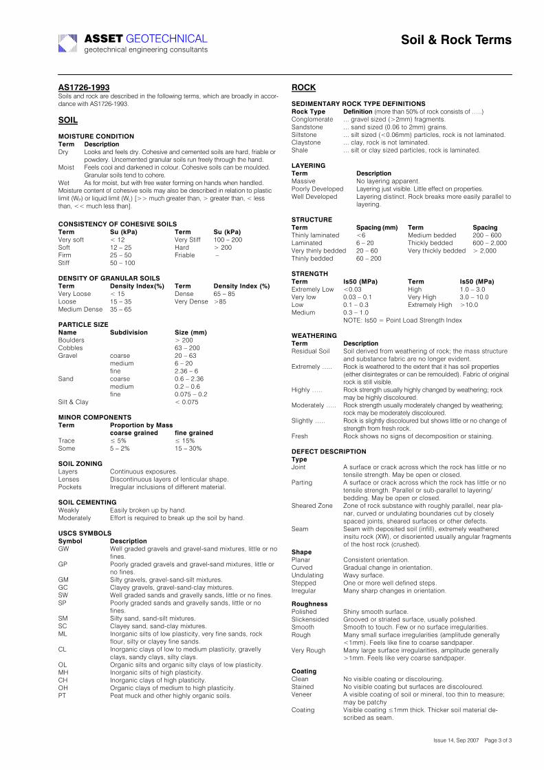
5,TUVWXTYYZ)<.357!42I!6.0O!46-!I-7063H-I!32!/1-!B.55.J32,!/-6P7;!J1301!46-!H6.4I5M!32!400.6LI420-!J3/1!*<9@>fL9ggCN!!!,.!4));.!,8<20)-.67!8!.6)8F%"! 7FJC%+#&+$(!V6M! +..O7!42I!B--57!I6MN!&.1-73K-!42I!0-P-2/-I!7.357!46-!146I;!B634H5-!.6!
=.JI-6MN!`20-P-2/-I!,6428546!7.357!682!B6--5M!/16.8,1!/1-!142IN!^.37/! b--57!0..5!42I!I46O-2-I!32!0.5.86N!&.1-73K-!7.357!042!H-!P.85I-IN!
"6428546!7.357!/-2I!/.!0.1-6-N!W-/! *7!B.6!P.37/;!H8/!J3/1!B6--!J4/-6!B.6P32,!.2!142I7!J1-2!142I5-IN!^.37/86-!0.2/-2/!.B!0.1-73K-!7.357!P4M!457.!H-!I-7063H-I!32!6-54/3.2!/.!=547/30!53P3/!DWAG!.6!53U83I!53P3/!DW+G!hdd!P801!,6-4/-6!/142;!d!,6-4/-6!/142;!i!5-77!/142;!ii!P801!5-77!/142jN!!!-.6,!,806-@).1)-.:0,!30),.!4,!8F%"!! ! ! ,H)LD/'N) ) ) 8F%") ) ,H)LD/'N!]-6M!7.B/!! ! i!9>! ! ! ! ]-6M!</3BB!!! 9??!k!>??!<.B/!! ! ! 9>!k!>a! ! ! ! '46I! ! d!>??!b36P!! ! ! >a!k!a?! ! ! ! b634H5-! ! !k!!</3BB!! ! ! a?!k!9??!!706,!8@).1)9256<452),.!4,)8F%"! ! ! 7F(J+&S)!(IF[LMN)) 8F%") ) 7F(J+&S)!(IF[)LMN!]-6M!+..7-! ! i!9a! ! ! ! V-27-! ! fa!k!la!+..7-! ! ! 9a!k!Ca! ! ! ! ]-6M!V-27-! dla!^-I38P!V-27-! Ca!k!fa!!/528!-40),!\0)6'"F! ! ! ,HPI+Q+J+$(!! ! ,+]F)L""N!Z.85I-67! !! ! ! ! ! ! d!>??!&.HH5-7!!! ! ! ! ! ! ! fC!k!>??!"64K-5! ! ! 0.467-! ! ! ! >?!k!fC!!! ! ! ! P-I38P!! ! ! f!k!>?!!! ! ! ! B32-!! ! ! ! >NCf!k!f!<42I! ! ! 0.467-! ! ! ! ?Nf!k!>NCf!!! ! ! ! P-I38P!! ! ! ?N>!k!?Nf!!! ! ! ! B32-!! ! ! ! ?N?@a!k!?N>!<35/!m!&54M! ! ! ! ! ! ! i!?N?@a!);!6.2)-.;/.6068,)8F%"! ! ! /%$#$%&+$()PS);'JJ)! ! ! ! C$'%JF)O%'+(FI) ) *+(F)O%'+(FI!%640-! ! ! �!an! ! ! ! �!9an!<.P-! ! ! a!k!>n! ! ! ! 9a!k!C?n!),.!4)\.6!69!+4M-67! ! ! &.2/328.87!-S=.786-7N!+-27-7! ! ! V370.2/328.87!54M-67!.B!5-2/308546!714=-N!A.0O-/7!! ! )66-,8546!3205873.27!.B!I3BB-6-2/!P4/-6345N!!,.!4)-0;068!69!W-4O5M!! ! ! #4735M!H6.O-2!8=!HM!142IN!^.I-64/-5M!! ! #BB.6/!37!6-U836-I!/.!H6-4O!8=!/1-!7.35!HM!142IN!)<,-,),@;=.4,!,S"P$B!! ! 7FJC%+#&+$(!"W! W-55!,64I-I!,64K-57!42I!,64K-5L742I!P3S/86-7;!53//5-!.6!2.!
B32-7N!"A! A..65M!,64I-I!,64K-57!42I!,64K-5L742I!P3S/86-7;!53//5-!.6!
2.!B32-7N!"^! <35/M!,64K-57;!,64K-5L742IL735/!P3S/86-7N!"&! &54M-M!,64K-57;!,64K-5L742IL054M!P3S/86-7N!<W! W-55!,64I-I!742I7!42I!,64K-55M!742I7;!53//5-!.6!2.!B32-7N!<A! A..65M!,64I-I!742I7!42I!,64K-55M!742I7;!53//5-!.6!2.!
B32-7N!<^! <35/M!742I;!742IL735/!P3S/86-7N!<&! &54M-M!742I;!742IL054M!P3S/86-7N!^+! )2.6,4230!735/7!.B!5.J!=547/303/M;!K-6M!B32-!742I7;!6.0O!
B5.86;!735/M!.6!054M-M!B32-!742I7N!&+! )2.6,4230!054M7!.B!5.J!/.!P-I38P!=547/303/M;!,64K-55M!
054M7;!742IM!054M7;!735/M!054M7N!$+! $6,4230!735/7!42I!.6,4230!735/M!054M7!.B!5.J!=547/303/MN!^'! )2.6,4230!735/7!.B!13,1!=547/303/MN!&'! )2.6,4230!054M7!.B!13,1!=547/303/MN!$'! $6,4230!054M7!.B!P-I38P!/.!13,1!=547/303/MN!A%! A-4/!P80O!42I!./1-6!13,15M!.6,4230!7.357N!
2.-^)),07!;06852@)2.-^)8@/0)701!6!8!.6,)2$CD)8S#F! ! 7F*+(+&+$(!DP.6-!/142!a?n!.B!6.0O!0.2737/7!.B!oNNG!&.2,5.P-64/-! NNN!,64K-5!73R-I!Dd>PPG!B64,P-2/7N!<42I7/.2-! NNN!742I!73R-I!D?N?f!/.!>PPG!,64327N!<35/7/.2-! NNN!735/!73R-I!Di?N?fPPG!=46/305-7;!6.0O!37!2./!54P324/-IN!&54M7/.2-! NNN!054M;!6.0O!37!2./!54P324/-IN!<145-! NNN!735/!.6!054M!73R-I!=46/305-7;!6.0O!37!54P324/-IN!!45@02!69)8F%"! 7FJC%+#&+$(!^4773K-! (.!54M-632,!4==46-2/N!A..65M!V-K-5.=-I! +4M-632,!T87/!K373H5-N!+3//5-!-BB-0/!.2!=6.=-6/3-7N!W-55!V-K-5.=-I! +4M-632,!I37/320/N!X.0O!H6-4O7!P.6-!-4735M!=46455-5!/.!
54M-632,N!!,82<-8<20)8F%"! ! ! ! ,#'C+(O)L""N) 8F%") ) ) ) ,#'C+(O!%1325M!54P324/-I! ! if! ! ! ! ^-I38P!H-II-I! ! >??!k!f??!+4P324/-I! ! ! f!k!>?! ! ! %130O5M!H-II-I! ! f??!k!>;???!]-6M!/1325M!H-II-I! >?!k!f?! ! ! ]-6M!/130O5M!H-II-I! d!>;???!%1325M!H-II-I! ! f?!k!>??!! !!,820698:)8F%"! ! ! !J_`)L;/'N) ) ) 8F%") ) ) !J_`)L;/'N)#S/6-P-5M!+.J! i?N?C! ! ! ! '3,1! ! ! 9N?!k!CN?!]-6M!5.J!! ! ?N?C!k!?N9! ! ! ]-6M!'3,1! ! CN?!k!9?N?!+.J!! ! ! ?N9!k!?NC!! ! ! #S/6-P-5M!'3,1! d9?N?!^-I38P!! ! ?NC!k!9N?!! ! ! ! ($%#p!)7a?!c!A.32/!+.4I!</6-2,/1!)2I-S!!G058:02!69)8F%"! 7FJC%+#&+$(!X-73I845!<.35! <.35!I-63K-I!B6.P!J-4/1-632,!.B!6.0Oq!/1-!P477!7/680/86-!
42I!78H7/420-!B4H630!46-!2.!5.2,-6!-K3I-2/N!#S/6-P-5M!oNN! X.0O!37!J-4/1-6-I!/.!/1-!-S/-2/!/14/!3/!147!7.35!=6.=-6/3-7!
D-3/1-6!I3732/-,64/-7!.6!042!H-!6-P.85I-IGN!b4H630!.B!.63,3245!6.0O!37!7/355!K373H5-N!
'3,15M!oNN! X.0O!7/6-2,/1!878455M!13,15M!0142,-I!HM!J-4/1-632,q!6.0O!P4M!H-!13,15M!I370.5.86-IN!
^.I-64/-5M!oNN! X.0O!7/6-2,/1!878455M!P.I-64/-5M!0142,-I!HM!J-4/1-632,q!6.0O!P4M!H-!P.I-64/-5M!I370.5.86-IN!
<53,1/5M!oNN! X.0O!37!753,1/5M!I370.5.86-I!H8/!71.J7!53//5-!.6!2.!0142,-!.B!7/6-2,/1!B6.P!B6-71!6.0ON!
b6-71! X.0O!71.J7!2.!73,27!.B!I-0.P=.73/3.2!.6!7/43232,N!!7010-8)70,-2!/8!.6)8S#F!e.32/! *!786B40-!.6!0640O!406.77!J1301!/1-!6.0O!147!53//5-!.6!2.!
/-2735-!7/6-2,/1N!^4M!H-!.=-2!.6!05.7-IN!A46/32,! *!786B40-!.6!0640O!406.77!J1301!/1-!6.0O!147!53//5-!.6!2.!
/-2735-!7/6-2,/1N!A46455-5!.6!78HL=46455-5!/.!54M-632,QH-II32,N!^4M!H-!.=-2!.6!05.7-IN!
<1-46-I!\.2-! \.2-!.B!6.0O!78H7/420-!J3/1!6.8,15M!=46455-5;!2-46!=54L246;!086K-I!.6!82I854/32,!H.82I463-7!08/!HM!05.7-5M!7=40-I!T.32/7;!71-46-I!786B40-7!.6!./1-6!I-B-0/7N!
<-4P! <-4P!J3/1!I-=.73/-I!7.35!D32B355G;!-S/6-P-5M!J-4/1-6-I!3273/8!6.0O!D[WG;!.6!I37.63-2/-I!878455M!42,8546!B64,P-2/7!.B!/1-!1.7/!6.0O!D06871-IGN!
,E'#F)A54246! &.2737/-2/!.63-2/4/3.2N!&86K-I! "64I845!0142,-!32!.63-2/4/3.2N!`2I854/32,! W4KM!786B40-N!</-==-I! $2-!.6!P.6-!J-55!I-B32-I!7/-=7N!)66-,8546! ^42M!7146=!0142,-7!32!.63-2/4/3.2N!
2$HOE(FJJ!A.5371-I! <132M!7P../1!786B40-N!<530O-273I-I! "6..K-I!.6!7/634/-I!786B40-;!878455M!=.5371-IN!<P../1! <P../1!/.!/.801N!b-J!.6!2.!786B40-!366-,85463/3-7N!X.8,1! ^42M!7P455!786B40-!366-,85463/3-7!D4P=53/8I-!,-2-6455M!
i9PPGN!b--57!53O-!B32-!/.!0.467-!742I=4=-6N!]-6M!X.8,1! ^42M!546,-!786B40-!366-,85463/3-7;!4P=53/8I-!,-2-6455M!
d9PPN!b--57!53O-!K-6M!0.467-!742I=4=-6N!!-$'&+(O!&5-42! (.!K373H5-!0.4/32,!.6!I370.5.8632,N!</432-I! (.!K373H5-!0.4/32,!H8/!786B40-7!46-!I370.5.86-IN!]-2--6! *!K373H5-!0.4/32,!.B!7.35!.6!P32-645;!/..!/132!/.!P-4786-q!
P4M!H-!=4/01M!&.4/32,! ]373H5-!0.4/32,!�9PP!/130ON!%130O-6!7.35!P4/-6345!I-L
7063H-I!47!7-4PN!
,$+B)R)2$CD)8F%"J)!""#$!"#$%#&'()&*+!,-./-0123045!-2,32--632,!0.2785/42/7!
!
Soil Types
The types of soils usually present under the topsoil in land zoned forresidential buildings can be split into two approximate groups –granular and clay. Quite often, foundation soil is a mixture of bothtypes. The general problems associated with soils having granularcontent are usually caused by erosion. Clay soils are subject tosaturation and swell/shrink problems.
Classifications for a given area can generally be obtained byapplication to the local authority, but these are sometimes unreliableand if there is doubt, a geotechnical report should be commissioned.As most buildings suffering movement problems are founded on claysoils, there is an emphasis on classification of soils according to theamount of swell and shrinkage they experience with variations ofwater content. The table below is Table 2.1 from AS 2870, theResidential Slab and Footing Code.
Causes of Movement
Settlement due to constructionThere are two types of settlement that occur as a result ofconstruction:• Immediate settlement occurs when a building is first placed on its
foundation soil, as a result of compaction of the soil under theweight of the structure. The cohesive quality of clay soil mitigatesagainst this, but granular (particularly sandy) soil is susceptible.
• Consolidation settlement is a feature of clay soil and may takeplace because of the expulsion of moisture from the soil or becauseof the soil’s lack of resistance to local compressive or shear stresses.This will usually take place during the first few months afterconstruction, but has been known to take many years inexceptional cases.
These problems are the province of the builder and should be takeninto consideration as part of the preparation of the site for construc-tion. Building Technology File 19 (BTF 19) deals with theseproblems.
ErosionAll soils are prone to erosion, but sandy soil is particularly susceptibleto being washed away. Even clay with a sand component of say 10%or more can suffer from erosion.
SaturationThis is particularly a problem in clay soils. Saturation creates a bog-like suspension of the soil that causes it to lose virtually all of itsbearing capacity. To a lesser degree, sand is affected by saturationbecause saturated sand may undergo a reduction in volume –particularly imported sand fill for bedding and blinding layers.However, this usually occurs as immediate settlement and shouldnormally be the province of the builder.
Seasonal swelling and shrinkage of soilAll clays react to the presence of water by slowly absorbing it, makingthe soil increase in volume (see table below). The degree of increasevaries considerably between different clays, as does the degree ofdecrease during the subsequent drying out caused by fair weatherperiods. Because of the low absorption and expulsion rate, thisphenomenon will not usually be noticeable unless there areprolonged rainy or dry periods, usually of weeks or months,depending on the land and soil characteristics.
The swelling of soil creates an upward force on the footings of thebuilding, and shrinkage creates subsidence that takes away thesupport needed by the footing to retain equilibrium.
Shear failureThis phenomenon occurs when the foundation soil does not havesufficient strength to support the weight of the footing. There aretwo major post-construction causes:• Significant load increase.• Reduction of lateral support of the soil under the footing due to
erosion or excavation.• In clay soil, shear failure can be caused by saturation of the soil
adjacent to or under the footing.
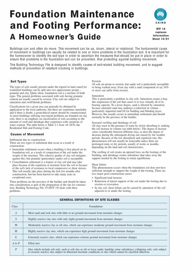
Buildings can and often do move . This movement can be up , down, la tera l or rota tiona l. The fundamenta l causeof movement in buildings can usua lly be rela ted to one or more problems in the founda tion soil. It is important forthe homeowner to identify the soil type in order to ascerta in the measures tha t should be put in place in order toensure tha t problems in the founda tion soil can be prevented , thus protecting aga inst building movement.
This Building Technology File is designed to identify causes of soil-rela ted building movement, and to suggestmethods of prevention of resultant cracking in buildings.
Foundation Maintenanceand Footing Performance:A Homeowner ’s Guide
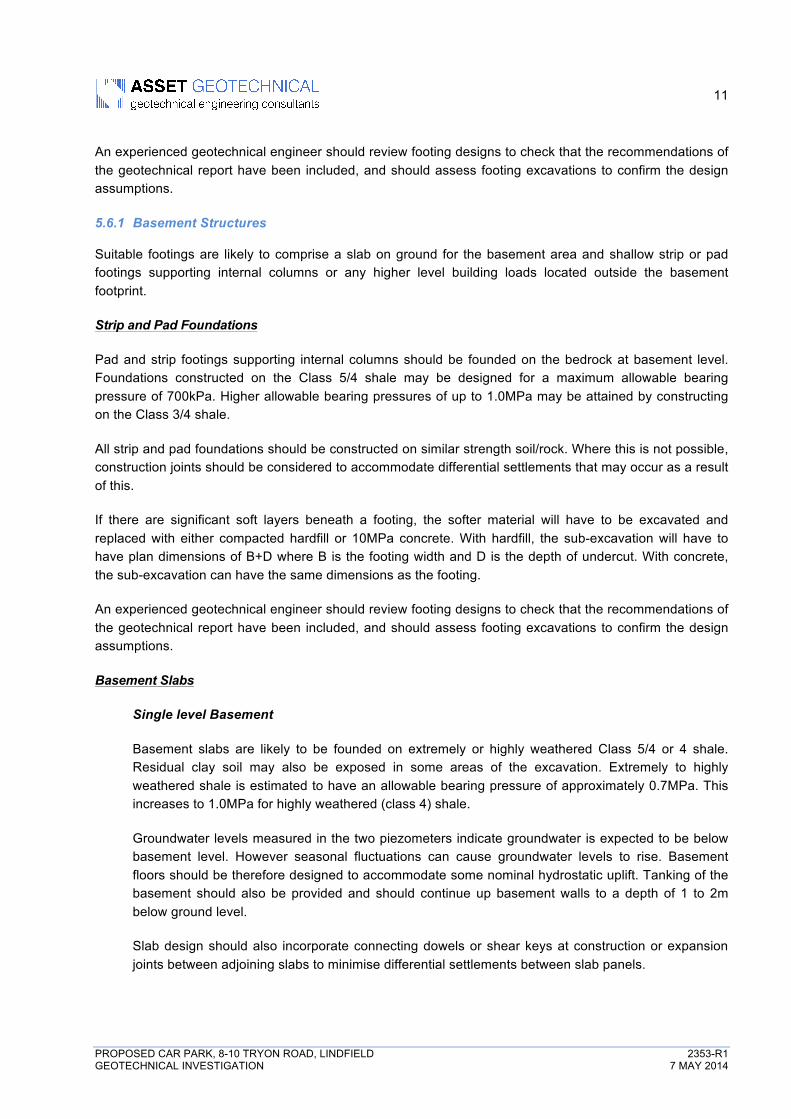
GENERAL DEFINITIONS OF SITE CLASSES
Class Foundation
A Most sand and rock sites with little or no ground movement from moisture changes
S Slightly reactive clay sites with only slight ground movement from moisture changes
M Moderately reactive clay or silt sites, which can experience moderate ground movement from moisture changes
H Highly reactive clay sites, which can experience high ground movement from moisture changes
E Extremely reactive sites, which can experience extreme ground movement from moisture changes
A to P Filled sites
P Sites which include soft soils, such as soft clay or silt or loose sands; landslip; mine subsidence; collapsing soils; soils subject to erosion; reactive sites subject to abnormal moisture conditions or sites which cannot be classified otherwise
BTF 18replaces
InformationSheet 10 / 91

Tree root growthTrees and shrubs that are allowed to grow in the vicinity of footingscan cause foundation soil movement in two ways:
• Roots that grow under footings may increase in cross-sectionalsize, exerting upward pressure on footings.
• Roots in the vicinity of footings will absorb much of the moisturein the foundation soil, causing shrinkage or subsidence.
Unevenness of Movement
The types of ground movement described above usually occurunevenly throughout the building’s foundation soil. Settlement dueto construction tends to be uneven because of:
• Differing compaction of foundation soil prior to construction.• Differing moisture content of foundation soil prior to construction.
Movement due to non-construction causes is usually more unevenstill. Erosion can undermine a footing that traverses the flow or cancreate the conditions for shear failure by eroding soil adjacent to afooting that runs in the same direction as the flow.
Saturation of clay foundation soil may occur where subfloor wallscreate a dam that makes water pond. It can also occur wherever thereis a source of water near footings in clay soil. This leads to a severereduction in the strength of the soil which may create local shearfailure.
Seasonal swelling and shrinkage of clay soil affects the perimeter ofthe building first, then gradually spreads to the interior. The swellingprocess will usually begin at the uphill extreme of the building, or onthe weather side where the land is flat. Swelling gradually reaches theinterior soil as absorption continues. Shrinkage usually begins wherethe sun’s heat is greatest.
Effects of Uneven Soil Movement on Structures
Erosion and saturationErosion removes the support from under footings, tending to createsubsidence of the part of the structure under which it occurs.Brickwork walls will resist the stress created by this removal ofsupport by bridging the gap or cantilevering until the bricks or themortar bedding fail. Older masonry has little resistance. Evidence offailure varies according to circumstances and symptoms may include:
• Step cracking in the mortar beds in the body of the wall orabove/below openings such as doors or windows.
• Vertical cracking in the bricks (usually but not necessarily in linewith the vertical beds or perpends).
Isolated piers affected by erosion or saturation of foundations willeventually lose contact with the bearers they support and may tilt orfall over. The floors that have lost this support will become bouncy,sometimes rattling ornaments etc.
Seasonal swelling/shrinkage in claySwelling foundation soil due to rainy periods first lifts the mostexposed extremities of the footing system, then the remainder of theperimeter footings while gradually permeating inside the buildingfootprint to lift internal footings. This swelling first tends to create adish effect, because the external footings are pushed higher than theinternal ones.
The first noticeable symptom may be that the floor appears slightlydished. This is often accompanied by some doors binding on thefloor or the door head, together with some cracking of cornicemitres. In buildings with timber flooring supported by bearers andjoists, the floor can be bouncy. Externally there may be visibledishing of the hip or ridge lines.
As the moisture absorption process completes its journey to theinnermost areas of the building, the internal footings will rise. If thespread of moisture is roughly even, it may be that the symptoms willtemporarily disappear, but it is more likely that swelling will beuneven, creating a difference rather than a disappearance insymptoms. In buildings with timber flooring supported by bearersand joists, the isolated piers will rise more easily than the stripfootings or piers under walls, creating noticeable doming of flooring.
As the weather pattern changes and the soil begins to dry out, theexternal footings will be first affected, beginning with the locationswhere the sun’s effect is strongest. This has the effect of lowering theexternal footings. The doming is accentuated and cracking reducesor disappears where it occurred because of dishing, but other cracksopen up. The roof lines may become convex.
Doming and dishing are also affected by weather in other ways. Inareas where warm, wet summers and cooler dry winters prevail,water migration tends to be toward the interior and doming will beaccentuated, whereas where summers are dry and winters are coldand wet, migration tends to be toward the exterior and theunderlying propensity is toward dishing.
Movement caused by tree rootsIn general, growing roots will exert an upward pressure on footings,whereas soil subject to drying because of tree or shrub roots will tendto remove support from under footings by inducing shrinkage.
Complications caused by the structure itselfMost forces that the soil causes to be exerted on structures arevertical – i.e. either up or down. However, because these forces areseldom spread evenly around the footings, and because the buildingresists uneven movement because of its rigidity, forces are exertedfrom one part of the building to another. The net result of all theseforces is usually rotational. This resultant force often complicates thediagnosis because the visible symptoms do not simply reflect theoriginal cause. A common symptom is binding of doors on thevertical member of the frame.
Effects on full masonry structuresBrickwork will resist cracking where it can. It will attempt to spanareas that lose support because of subsided foundations or raisedpoints. It is therefore usual to see cracking at weak points, such asopenings for windows or doors.
In the event of construction settlement, cracking will usually remainunchanged after the process of settlement has ceased.
With local shear or erosion, cracking will usually continue to developuntil the original cause has been remedied, or until the subsidencehas completely neutralised the affected portion of footing and thestructure has stabilised on other footings that remain effective.
In the case of swell/shrink effects, the brickwork will in some casesreturn to its original position after completion of a cycle, however itis more likely that the rotational effect will not be exactly reversed,and it is also usual that brickwork will settle in its new position andwill resist the forces trying to return it to its original position. Thismeans that in a case where swelling takes place after constructionand cracking occurs, the cracking is likely to at least partly remainafter the shrink segment of the cycle is complete. Thus, each timethe cycle is repeated, the likelihood is that the cracking will becomewider until the sections of brickwork become virtually independent.
With repeated cycles, once the cracking is established, if there is noother complication, it is normal for the incidence of cracking tostabilise, as the building has the articulation it needs to cope withthe problem. This is by no means always the case, however, andmonitoring of cracks in walls and floors should always be treatedseriously.
Upheaval caused by growth of tree roots under footings is not asimple vertical shear stress. There is a tendency for the root to alsoexert lateral forces that attempt to separate sections of brickworkafter initial cracking has occurred.
Trees can cause shrinkage and damage
The normal structural arrangement is that the inner leaf of brick-work in the external walls and at least some of the internal walls(depending on the roof type) comprise the load-bearing structure onwhich any upper floors, ceilings and the roof are supported. In thesecases, it is internally visible cracking that should be the main focusof attention, however there are a few examples of dwellings whoseexternal leaf of masonry plays some supporting role, so this shouldbe checked if there is any doubt. In any case, externally visiblecracking is important as a guide to stresses on the structure generally,and it should also be remembered that the external walls must becapable of supporting themselves.
Effects on framed structuresTimber or steel framed buildings are less likely to exhibit crackingdue to swell/shrink than masonry buildings because of theirflexibility. Also, the doming/dishing effects tend to be lower becauseof the lighter weight of walls. The main risks to framed buildings areencountered because of the isolated pier footings used under walls.Where erosion or saturation cause a footing to fall away, this candouble the span which a wall must bridge. This additional stress cancreate cracking in wall linings, particularly where there is a weakpoint in the structure caused by a door or window opening. It is,however, unlikely that framed structures will be so stressed as to sufferserious damage without first exhibiting some or all of the abovesymptoms for a considerable period. The same warning period shouldapply in the case of upheaval. It should be noted, however, that whereframed buildings are supported by strip footings there is only one leafof brickwork and therefore the externally visible walls are thesupporting structure for the building. In this case, the subfloormasonry walls can be expected to behave as full brickwork walls.
Effects on brick veneer structuresBecause the load-bearing structure of a brick veneer building is theframe that makes up the interior leaf of the external walls plusperhaps the internal walls, depending on the type of roof, thebuilding can be expected to behave as a framed structure, except thatthe external masonry will behave in a similar way to the external leafof a full masonry structure.
Water Service and Drainage
Where a water service pipe, a sewer or stormwater drainage pipe is inthe vicinity of a building, a water leak can cause erosion, swelling orsaturation of susceptible soil. Even a minuscule leak can be enoughto saturate a clay foundation. A leaking tap near a building can havethe same effect. In addition, trenches containing pipes can becomewatercourses even though backfilled, particularly where brokenrubble is used as fill. Water that runs along these trenches can beresponsible for serious erosion, interstrata seepage into subfloor areasand saturation.
Pipe leakage and trench water flows also encourage tree and shrubroots to the source of water, complicating and exacerbating theproblem.Poor roof plumbing can result in large volumes of rainwater beingconcentrated in a small area of soil:
• Incorrect falls in roof guttering may result in overflows, as maygutters blocked with leaves etc.
• Corroded guttering or downpipes can spill water to ground.• Downpipes not positively connected to a proper stormwater
collection system will direct a concentration of water to soil that isdirectly adjacent to footings, sometimes causing large-scaleproblems such as erosion, saturation and migration of water underthe building.
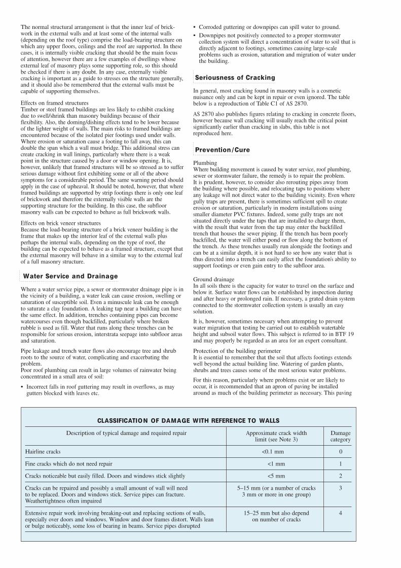
Seriousness of Cracking
In general, most cracking found in masonry walls is a cosmeticnuisance only and can be kept in repair or even ignored. The tablebelow is a reproduction of Table C1 of AS 2870.
AS 2870 also publishes figures relating to cracking in concrete floors,however because wall cracking will usually reach the critical pointsignificantly earlier than cracking in slabs, this table is notreproduced here.
Prevention / Cure
PlumbingWhere building movement is caused by water service, roof plumbing,sewer or stormwater failure, the remedy is to repair the problem. It is prudent, however, to consider also rerouting pipes away fromthe building where possible, and relocating taps to positions whereany leakage will not direct water to the building vicinity. Even wheregully traps are present, there is sometimes sufficient spill to createerosion or saturation, particularly in modern installations usingsmaller diameter PVC fixtures. Indeed, some gully traps are notsituated directly under the taps that are installed to charge them,with the result that water from the tap may enter the backfilledtrench that houses the sewer piping. If the trench has been poorlybackfilled, the water will either pond or flow along the bottom ofthe trench. As these trenches usually run alongside the footings andcan be at a similar depth, it is not hard to see how any water that isthus directed into a trench can easily affect the foundation’s ability tosupport footings or even gain entry to the subfloor area.
Ground drainageIn all soils there is the capacity for water to travel on the surface andbelow it. Surface water flows can be established by inspection duringand after heavy or prolonged rain. If necessary, a grated drain systemconnected to the stormwater collection system is usually an easysolution.
It is, however, sometimes necessary when attempting to preventwater migration that testing be carried out to establish watertableheight and subsoil water flows. This subject is referred to in BTF 19and may properly be regarded as an area for an expert consultant.
Protection of the building perimeterIt is essential to remember that the soil that affects footings extendswell beyond the actual building line. Watering of garden plants,shrubs and trees causes some of the most serious water problems.
For this reason, particularly where problems exist or are likely tooccur, it is recommended that an apron of paving be installedaround as much of the building perimeter as necessary. This paving
CLASSIFICATION OF DAMAGE WITH REFERENCE TO WALLS
Description of typical damage and required repair Approximate crack width Damagelimit (see Note 3) category
Hairline cracks <0.1 mm 0
Fine cracks which do not need repair <1 mm 1
Cracks noticeable but easily filled. Doors and windows stick slightly <5 mm 2
Cracks can be repaired and possibly a small amount of wall will need 5–15 mm (or a number of cracks 3to be replaced. Doors and windows stick. Service pipes can fracture. 3 mm or more in one group)Weathertightness often impaired
Extensive repair work involving breaking-out and replacing sections of walls, 15–25 mm but also depend 4especially over doors and windows. Window and door frames distort. Walls lean on number of cracksor bulge noticeably, some loss of bearing in beams. Service pipes disrupted
should extend outwards a minimum of 900 mm (more in highlyreactive soil) and should have a minimum fall away from thebuilding of 1:60. The finished paving should be no less than 100mm below brick vent bases.
It is prudent to relocate drainage pipes away from this paving, ifpossible, to avoid complications from future leakage. If this is notpractical, earthenware pipes should be replaced by PVC andbackfilling should be of the same soil type as the surrounding soiland compacted to the same density.
Except in areas where freezing of water is an issue, it is wise toremove taps in the building area and relocate them well away fromthe building – preferably not uphill from it (see BTF 19).
It may be desirable to install a grated drain at the outside edge of thepaving on the uphill side of the building. If subsoil drainage isneeded this can be installed under the surface drain.
CondensationIn buildings with a subfloor void such as where bearers and joistssupport flooring, insufficient ventilation creates ideal conditions forcondensation, particularly where there is little clearance between thefloor and the ground. Condensation adds to the moisture alreadypresent in the subfloor and significantly slows the process of dryingout. Installation of an adequate subfloor ventilation system, eithernatural or mechanical, is desirable.
Warning: Although this Building Technology File deals withcracking in buildings, it should be said that subfloor moisture canresult in the development of other problems, notably:
• Water that is transmitted into masonry, metal or timber buildingelements causes damage and/or decay to those elements.
• High subfloor humidity and moisture content create an idealenvironment for various pests, including termites and spiders.
• Where high moisture levels are transmitted to the flooring andwalls, an increase in the dust mite count can ensue within theliving areas. Dust mites, as well as dampness in general, can be ahealth hazard to inhabitants, particularly those who areabnormally susceptible to respiratory ailments.
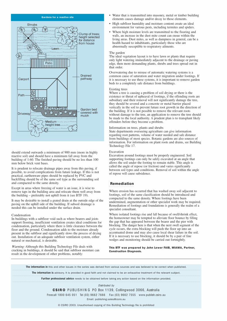
The gardenThe ideal vegetation layout is to have lawn or plants that requireonly light watering immediately adjacent to the drainage or pavingedge, then more demanding plants, shrubs and trees spread out inthat order.
Overwatering due to misuse of automatic watering systems is acommon cause of saturation and water migration under footings. Ifit is necessary to use these systems, it is important to remove gardenbeds to a completely safe distance from buildings.
Existing treesWhere a tree is causing a problem of soil drying or there is theexistence or threat of upheaval of footings, if the offending roots aresubsidiary and their removal will not significantly damage the tree,they should be severed and a concrete or metal barrier placedvertically in the soil to prevent future root growth in the direction ofthe building. If it is not possible to remove the relevant rootswithout damage to the tree, an application to remove the tree shouldbe made to the local authority. A prudent plan is to transplant likelyoffenders before they become a problem.
Information on trees, plants and shrubsState departments overseeing agriculture can give informationregarding root patterns, volume of water needed and safe distancefrom buildings of most species. Botanic gardens are also sources ofinformation. For information on plant roots and drains, see BuildingTechnology File 17.
ExcavationExcavation around footings must be properly engineered. Soilsupporting footings can only be safely excavated at an angle thatallows the soil under the footing to remain stable. This angle iscalled the angle of repose (or friction) and varies significantlybetween soil types and conditions. Removal of soil within the angleof repose will cause subsidence.
Remediation
Where erosion has occurred that has washed away soil adjacent tofootings, soil of the same classification should be introduced andcompacted to the same density. Where footings have beenundermined, augmentation or other specialist work may be required.Remediation of footings and foundations is generally the realm of aspecialist consultant.
Where isolated footings rise and fall because of swell/shrink effect,the homeowner may be tempted to alleviate floor bounce by fillingthe gap that has appeared between the bearer and the pier withblocking. The danger here is that when the next swell segment of thecycle occurs, the extra blocking will push the floor up into anaccentuated dome and may also cause local shear failure in the soil.If it is necessary to use blocking, it should be by a pair of finewedges and monitoring should be carried out fortnightly.
This BTF was prepared by John Lewer FAIB, MIAMA, Partner,Construction Diagnosis.
The information in this and other issues in the series was derived from various sources and was believed to be correct when published.
The information is advisory. It is provided in good faith and not claimed to be an exhaustive treatment of the relevant subject.
Further professional advice needs to be obtained before taking any action based on the information provided.
Distributed by
C S I R O P U B L I S H I N G P O Box 1139 , Collingwood 3066 , Austra liaFreeca ll 1800 645 051 Tel (03) 9662 7666 Fax (03) 9662 7555 www.publish.csiro.au
Email: [email protected]
© CSIRO 2003. Unauthorised copying of this Building Technology file is prohibited
Gardens for a reactive site
��� � ����
���
��
��
��
�������������
����
�������
�
�����
�����
!"#�"$%��&'(�($�)"**
�(#"+,&*
-(+./01
�����
����� ��2.&'(**3�0*&3(3�������*/4�5*&#�"0"�3��+.&1�6./4$��)"$(�/��(+",��%.&"$(+��&$%,*&.��/�#,6�&$%,*&.�%.&'(*
���7���(+",��5*&#�"0"�3��5&*(�%.(3��/��*(+�/.&$%(
���� ��5&*(�%.(3���8"$*3�*&�"$&�(+��(!�.(�(*34(&�8(.(+��(#�"�&�(+�(!�.(�(*3�*/4�#�.($%�8
6(0/�"$%�8"%8*3�4(&�8(.(+��(#�"�&�(+�'(.3�*/4��/*/4�#�.($%�8
���� ��6./4$�+&.1�.(+���8"$*3�*&�"$&�(+�8"%8*3�4(&�8(.(+��(#�"�&�(+�'(.3�*/4��/�*/4#�.($%�8
��/9���
#/"*��35(:�5*&#�"0"�3�/.�5&.�"0*(�08&.&0�(."#�"0#�0/*/,.��#(0/$+&.3�&$+��"$/.�0/�5/$($�#�
&55./!�
�����������
��������� �������� ����������� ��������
��
��
���
���(�8/
+
#,55
/.�
4&�(.
;��
��#3�6/
*
%.&5
8"0�*/%
+(5�8
�(�.(#
���
��
��
��
��
���
���
��
��
���
��$/�(#
#&�5*(#�
�(#�#��(�0
�/"#�,.(
0/$+
"�"/$
0/$#"#�($
03�
+($#"�3
�"$+(
!
1�&
8&$+
5($(
�./�
�(�(. ������������
���������������������
�##(��2(/�(08$"0&*� $%"$((."$%���3���+"$9/<&##(�%(/�(08$"0&*�0/��&,
�7�� 7�,"�(��������=��(*8"��+�/.�8��3+(����?����8:�����@�A��=���)&!:��������
-/.(8/*(��/%����('"#"/$��
�������������������
������� ������������������������ ���������
����������������������������������������������������
���
���
����� ����� B���-
C,�."$%�2&"��/,$0"*
�./5/#(+��&.��&.1�����.3/$��/&+���"$+9"(*+2(/�./6(���.&01��/,$�(+����
� ) ���D� E�������D���� ���)D��� �������D��D)�� ���������7�-D���;� �
��������������� �@�F ������� �� ��
������
������
������ �
��������������� � ��
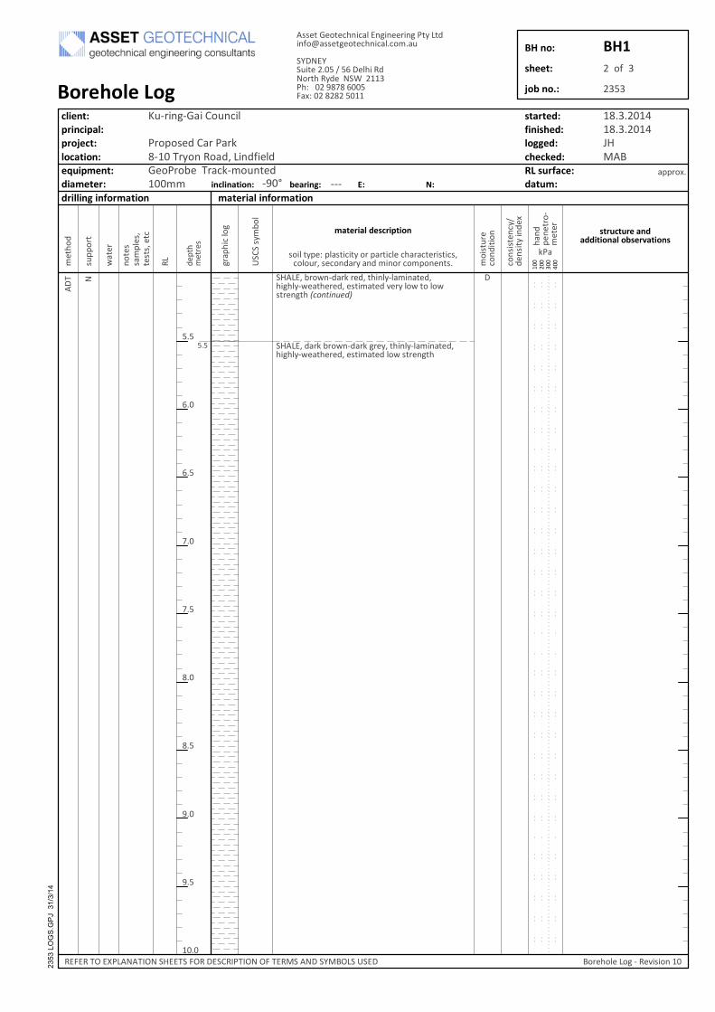
��� �
���
����� ��6./4$�+&.1�.(+���8"$*3�*&�"$&�(+�8"%8*3�4(&�8(.(+��(#�"�&�(+�'(.3�*/4��/�*/4#�.($%�8����������
���� ��+&.1�6./4$�+&.1�%.(3���8"$*3�*&�"$&�(+�8"%8*3�4(&�8(.(+��(#�"�&�(+�*/4�#�.($%�8
��/9���
#/"*��35(:�5*&#�"0"�3�/.�5&.�"0*(�08&.&0�(."#�"0#�0/*/,.��#(0/$+&.3�&$+��"$/.�0/�5/$($�#�
&55./!�
�����������
��������� �������� ����������� ��������
��
��
���
���(�8/
+
#,55
/.�
4&�(.
;��
��#3�6/
*
%.&5
8"0�*/%
+(5�8
�(�.(#
���
=��
=��
A��
A��
���
���
@��
@��
���
��$/�(#
#&�5*(#�
�(#�#��(�0
�/"#�,.(
0/$+
"�"/$
0/$#"#�($
03�
+($#"�3
�"$+(
!
1�&
8&$+
5($(
�./�
�(�(. ������������
���������������������
�##(��2(/�(08$"0&*� $%"$((."$%���3���+"$9/<&##(�%(/�(08$"0&*�0/��&,
�7�� 7�,"�(��������=��(*8"��+�/.�8��3+(����?����8:�����@�A��=���)&!:��������
-/.(8/*(��/%����('"#"/$��
�������������������
������� ������������������������ ���������
����������������������������������������������������
���
���
����� ����� B���-
C,�."$%�2&"��/,$0"*
�./5/#(+��&.��&.1�����.3/$��/&+���"$+9"(*+2(/�./6(���.&01��/,$�(+����
� ) ���D� E�������D���� ���)D��� �������D��D)�� ���������7�-D���;� �
��������������� �@�F ������� �� ��
������
������
������ �
��������������� � ��

��� �
���
����� ��+&.1�6./4$�+&.1�%.(3���8"$*3�*&�"$&�(+�8"%8*3�4(&�8(.(+��(#�"�&�(+�*/4�#�.($%�8���������
-/.(8/*(��/:�-���(.�"$&�(+�&������
���/9���
#/"*��35(:�5*&#�"0"�3�/.�5&.�"0*(�08&.&0�(."#�"0#�0/*/,.��#(0/$+&.3�&$+��"$/.�0/�5/$($�#�
&55./!�
�����������
��������� �������� ����������� ��������
��
��
���
���(�8/
+
#,55
/.�
4&�(.
;��
��#3�6/
*
%.&5
8"0�*/%
+(5�8
�(�.(#
���
��
��
��
��
���
���
��
��
���
��$/�(#
#&�5*(#�
�(#�#��(�0
�/"#�,.(
0/$+
"�"/$
0/$#"#�($
03�
+($#"�3
�"$+(
!
1�&
8&$+
5($(
�./�
�(�(. ������������
���������������������
�##(��2(/�(08$"0&*� $%"$((."$%���3���+"$9/<&##(�%(/�(08$"0&*�0/��&,
�7�� 7�,"�(��������=��(*8"��+�/.�8��3+(����?����8:�����@�A��=���)&!:��������
-/.(8/*(��/%����('"#"/$��
�������������������
������� ������������������������ ���������
����������������������������������������������������
���
���
����� ����� B���-
C,�."$%�2&"��/,$0"*
�./5/#(+��&.��&.1�����.3/$��/&+���"$+9"(*+2(/�./6(���.&01��/,$�(+����
� ) ���D� E�������D���� ���)D��� �������D��D)�� ���������7�-D���;� �
��������������� �@�F ������� �� ��
������
������
������ �
��������������� � ��

�;��
��;- � ����
���
�
�
��
��
���@����� ���=
�������
�
�����
�����
!"#�"$%��&'(�($�)"**
�(#"+,&*
-(+./01
�/$
(�D6#(.'(+ ����� ��
2.&'(**3����7���(+",��5*&#�"0"�3��6./4$��)"$(��/�(+",��%.&"$(+��&$%,*&.��/�#,6�&$%,*&.�%.&'(*�4"�8�#/�(�#"*�
���7���(+",��5*&#�"0"�3��5&*(�%.(3��/��*(+�5&*(6./4$
���� ��5&*(�%.(3���8"$*3�*&�"$&�(+��(!�.(�(*34(&�8(.(+��(#�"�&�(+�(!�.(�(*3�*/4��/�'(.3�*/4#�.($%�8
-/.(8/*(��/:�-���(.�"$&�(+�&��� �
��/9��
#/"*��35(:�5*&#�"0"�3�/.�5&.�"0*(�08&.&0�(."#�"0#�0/*/,.��#(0/$+&.3�&$+��"$/.�0/�5/$($�#�
&55./!�
�����������
��������� �������� ����������� ��������
��
��
���
���(�8/
+
#,55
/.�
4&�(.
;��
��#3�6/
*
%.&5
8"0�*/%
+(5�8
�(�.(#
���
��
��
��
��
���
���
��
��
���
��$/�(#
#&�5*(#�
�(#�#��(�0
�/"#�,.(
0/$+
"�"/$
0/$#"#�($
03�
+($#"�3
�"$+(
!
1�&
8&$+
5($(
�./�
�(�(. ������������
���������������������
�##(��2(/�(08$"0&*� $%"$((."$%���3���+"$9/<&##(�%(/�(08$"0&*�0/��&,
�7�� 7�,"�(��������=��(*8"��+�/.�8��3+(����?����8:�����@�A��=���)&!:��������
-/.(8/*(��/%����('"#"/$��
�������������������
������� ������������������������ ���������
����������������������������������������������������
��!
���
����� ����� B���-
C,�."$%�2&"��/,$0"*
�./5/#(+��&.��&.1�����.3/$��/&+���"$+9"(*+2(/�./6(���.&01��/,$�(+����
� ) ���D� E�������D���� ���)D��� �������D��D)�� ���������7�-D���;� �
��������������� �@�F ������� �� ��
������
������
������ �
��������������� � ��
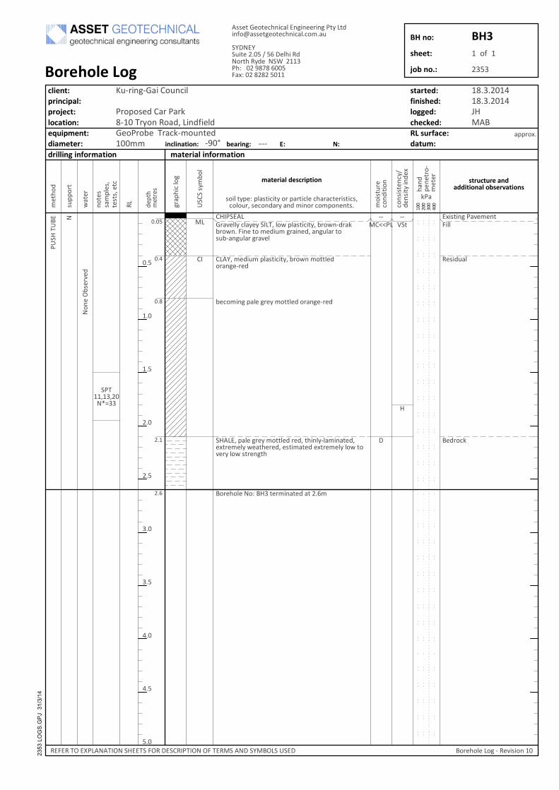
�;��
��;- � ����
��
���
�
�=
��
��
������������
��������
�
�����
�
!"#�"$%��&'(�($�)"**
�(#"+,&*
-(+./01
�/$
(�D6#(.'(+
����� ��2.&'(**3�0*&3(3�������*/4�5*&#�"0"�3��6./4$�+.&16./4$��)"$(��/��(+",��%.&"$(+��&$%,*&.��/#,6�&$%,*&.�%.&'(*
���7���(+",��5*&#�"0"�3��6./4$��/��*(+/.&$%(�.(+
6(0/�"$%�5&*(�%.(3��/��*(+�/.&$%(�.(+
���� ��5&*(�%.(3��/��*(+�.(+���8"$*3�*&�"$&�(+�(!�.(�(*3�4(&�8(.(+��(#�"�&�(+�(!�.(�(*3�*/4��/'(.3�*/4�#�.($%�8
-/.(8/*(��/:�-����(.�"$&�(+�&���=�
��/9��
#/"*��35(:�5*&#�"0"�3�/.�5&.�"0*(�08&.&0�(."#�"0#�0/*/,.��#(0/$+&.3�&$+��"$/.�0/�5/$($�#�
&55./!�
�����������
��������� �������� ����������� ��������
��
��
���
���(�8/
+
#,55
/.�
4&�(.
;��
��#3�6/
*
%.&5
8"0�*/%
+(5�8
�(�.(#
���
��
��
��
��
���
���
��
��
���
��$/�(#
#&�5*(#�
�(#�#��(�0
�/"#�,.(
0/$+
"�"/$
0/$#"#�($
03�
+($#"�3
�"$+(
!
1�&
8&$+
5($(
�./�
�(�(. ������������
���������������������
�##(��2(/�(08$"0&*� $%"$((."$%���3���+"$9/<&##(�%(/�(08$"0&*�0/��&,
�7�� 7�,"�(��������=��(*8"��+�/.�8��3+(����?����8:�����@�A��=���)&!:��������
-/.(8/*(��/%����('"#"/$��
�������������������
������� ������������������������ ���������
����������������������������������������������������
��"
���
����� ����� B���-
C,�."$%�2&"��/,$0"*
�./5/#(+��&.��&.1�����.3/$��/&+���"$+9"(*+2(/�./6(���.&01��/,$�(+����
� ) ���D� E�������D���� ���)D��� �������D��D)�� ���������7�-D���;� �
��������������� �@�F ������� �� ��
������
������
������ �
��������������� � ��
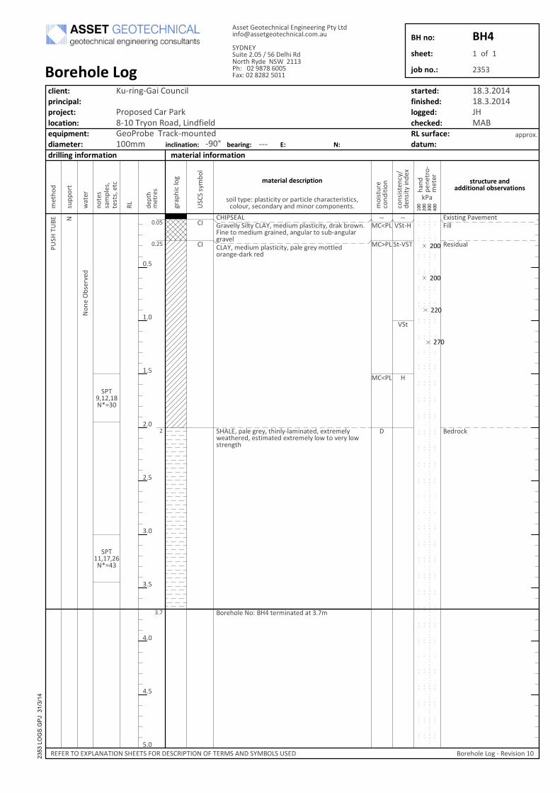
�;��
��;- � ����
���
��A
��
��
���@��������
����A�=��� �
�������
��G��
�����
�
�������
������
���
�
!"#�"$%��&'(�($�)"**
�(#"+,&*
-(+./01
�/$
(�D6#(.'(+
����� ��2.&'(**3��"*�3����7���(+",��5*&#�"0"�3��+.&1�6./4$�)"$(��/��(+",��%.&"$(+��&$%,*&.��/�#,6�&$%,*&.%.&'(*���7���(+",��5*&#�"0"�3��5&*(�%.(3��/��*(+/.&$%(�+&.1�.(+
���� ��5&*(�%.(3���8"$*3�*&�"$&�(+��(!�.(�(*34(&�8(.(+��(#�"�&�(+�(!�.(�(*3�*/4��/�'(.3�*/4#�.($%�8
-/.(8/*(��/:�-� ��(.�"$&�(+�&����A�
��/9��
#/"*��35(:�5*&#�"0"�3�/.�5&.�"0*(�08&.&0�(."#�"0#�0/*/,.��#(0/$+&.3�&$+��"$/.�0/�5/$($�#�
&55./!�
�����������
��������� �������� ����������� ��������
��
��
���
���(�8/
+
#,55
/.�
4&�(.
;��
��#3�6/
*
%.&5
8"0�*/%
+(5�8
�(�.(#
���
��
��
��
��
���
���
��
��
���
��$/�(#
#&�5*(#�
�(#�#��(�0
�/"#�,.(
0/$+
"�"/$
0/$#"#�($
03�
+($#"�3
�"$+(
!
1�&
8&$+
5($(
�./�
�(�(. ������������
���������������������
�##(��2(/�(08$"0&*� $%"$((."$%���3���+"$9/<&##(�%(/�(08$"0&*�0/��&,
�7�� 7�,"�(��������=��(*8"��+�/.�8��3+(����?����8:�����@�A��=���)&!:��������
-/.(8/*(��/%����('"#"/$��
�������������������
������� ������������������������ ���������
����������������������������������������������������
��#
���
����� ����� B���-
C,�."$%�2&"��/,$0"*
�./5/#(+��&.��&.1�����.3/$��/&+���"$+9"(*+2(/�./6(���.&01��/,$�(+����
� ) ���D� E�������D���� ���)D��� �������D��D)�� ���������7�-D���;� �
��������������� �@�F ������� �� ��
������
������
������ �
��������������� � ��
��
��
�
A�
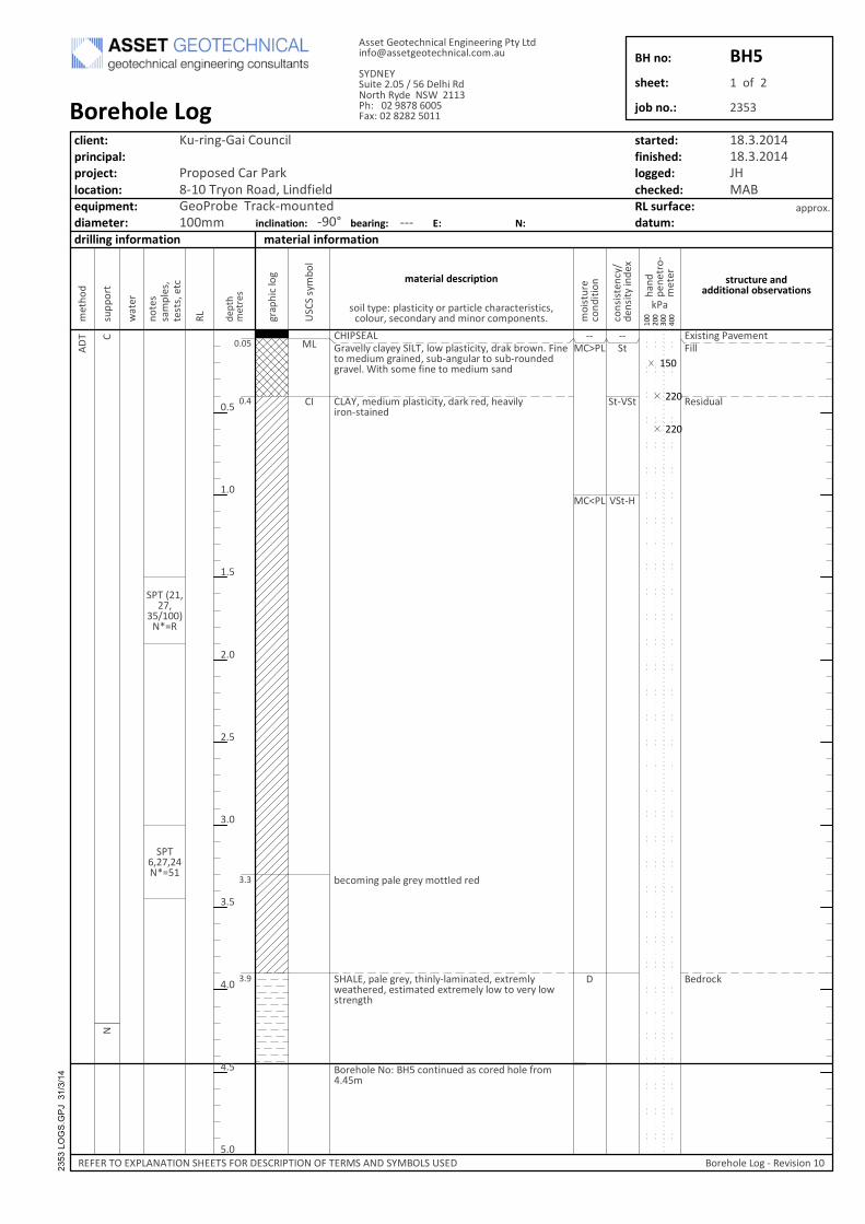
��� �
�
����
��
���
��@
��
��
����H�A�
�����I����
���=�A� ����
����G��
�����
�
����
������
�����
!"#�"$%��&'(�($�)"**
�(#"+,&*
-(+./01
����� ��2.&'(**3�0*&3(3�������*/4�5*&#�"0"�3��+.&1�6./4$��)"$(�/��(+",��%.&"$(+��#,6�&$%,*&.��/�#,6�./,$+(+%.&'(*��?"�8�#/�(�9"$(��/��(+",��#&$+
���7���(+",��5*&#�"0"�3��+&.1�.(+��8(&'"*3"./$�#�&"$(+
6(0/�"$%�5&*(�%.(3��/��*(+�.(+
���� ��5&*(�%.(3���8"$*3�*&�"$&�(+��(!�.(�*34(&�8(.(+��(#�"�&�(+�(!�.(�(*3�*/4��/�'(.3�*/4#�.($%�8
-/.(8/*(��/:�-���0/$�"$,(+�&#�0/.(+�8/*(�9./� � ��
��/9��
#/"*��35(:�5*&#�"0"�3�/.�5&.�"0*(�08&.&0�(."#�"0#�0/*/,.��#(0/$+&.3�&$+��"$/.�0/�5/$($�#�
&55./!�
�����������
��������� �������� ����������� ��������
��
��
���
���(�8/
+
#,55
/.�
4&�(.
;��
��#3�6/
*
%.&5
8"0�*/%
+(5�8
�(�.(#
���
��
��
��
��
���
���
��
��
���
��$/�(#
#&�5*(#�
�(#�#��(�0
�/"#�,.(
0/$+
"�"/$
0/$#"#�($
03�
+($#"�3
�"$+(
!
1�&
8&$+
5($(
�./�
�(�(. ������������
���������������������
�##(��2(/�(08$"0&*� $%"$((."$%���3���+"$9/<&##(�%(/�(08$"0&*�0/��&,
�7�� 7�,"�(��������=��(*8"��+�/.�8��3+(����?����8:�����@�A��=���)&!:��������
-/.(8/*(��/%����('"#"/$��
�������������������
������� ������������������������ ���������
����������������������������������������������������
��$
���
����� ����� B���-
C,�."$%�2&"��/,$0"*
�./5/#(+��&.��&.1�����.3/$��/&+���"$+9"(*+2(/�./6(���.&01��/,$�(+����
� ) ���D� E�������D���� ���)D��� �������D��D)�� ���������7�-D���;� �
��������������� �@�F ������� �� ��
������
������
������ �
��������������� � ��
��
�
�
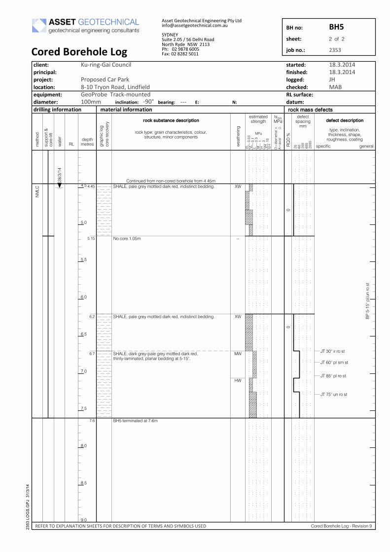
����
����
���
���
���
��
� �����
��
����������������������� � ��!��� ��"# "$�"#%��&� "#��
��%���������
����������������������� � ��!��� ��"# "$�"#%��&� "#��
������� ��!�����'���������������� � ��!��� ��("#��'���"#��� �����#���&� "#������'��)�
��#�"#*� �+����#�#'%��� �&���(����+���������
,�������"#��� ��������
-.���)�"�����$�
-.���)����$��$�
-.� �)�������$�
-.���)�*#����$�
/0
''
/0
0
�0
,1��'��)����*#����$�
����
���
���
� � ��
1�
����+���
2� ����("%����
%������%�3���
245�6
57 "��
�����
�7�8"�� ���(
�����$
���
���
���
���
���
���
���
��
��
9��
������"#%�"#��"�#��("%!#�$$��$(������*�(#�$$��%���"#�
���(�
:����
��
;� � � ;� ��
<$=��>1�
�+�%�$��%"#���
��������������
$*������?
%���'�"+�
�� �� ���
���
����
������ ����������������
��%!�����@����"#�%(���%���"$�"%$��%���*��$��*%�*�����"#���%����#�#�$
�$�"���� $���#��(
$��%"+"% ��#����:���(��"#�
�������������
���� �,���(��������'�2�3"$"�#�9
����������������
���� ��� �������� ��������� ��������
��������������� ����������������������������������� �������
��������������� �!� "��� ��$��������$�������%���&&'�(������)*,*�"�� -�.(����*�*�� �&&
���������� ������������������������������������
��� ����� ������������������� �������� �����������
���
�' '
&*�'���&/&*�'���&/012�3
4�5���5����6����
���7�����6������8*5&��9����$���:������� �������;���9���85������&����
$�-�$�9<��=�����9><���1��9��-<$����6$>�9><��<-�9�$2��������23<���?���
555� �� ���� � 5)�@ ����� �� �� ��
��� ��
������
���� � �
��������������� � ��
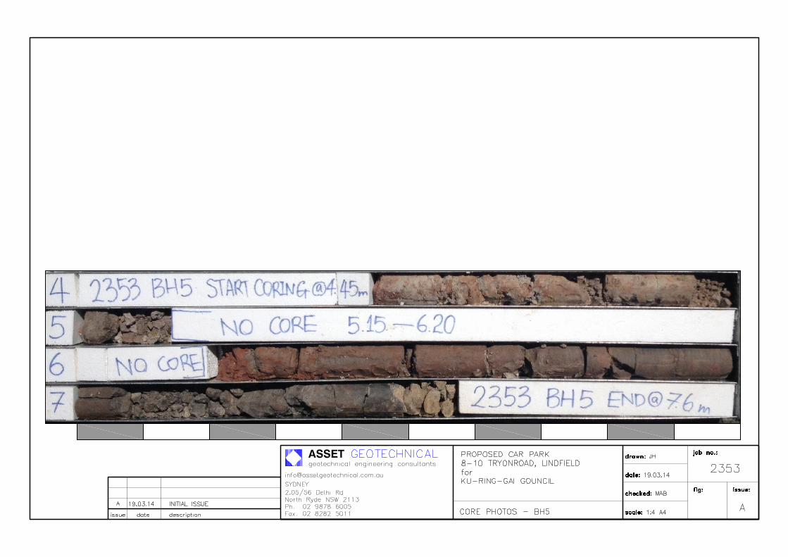
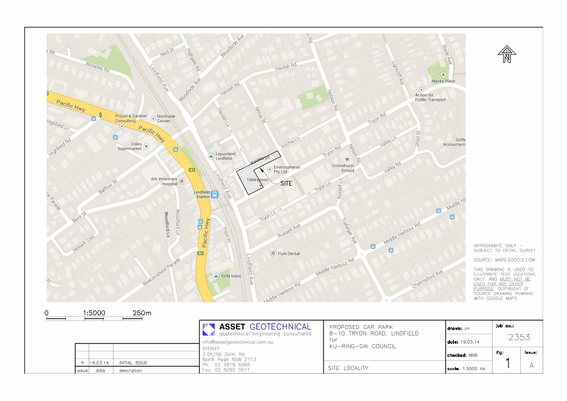
ASSET
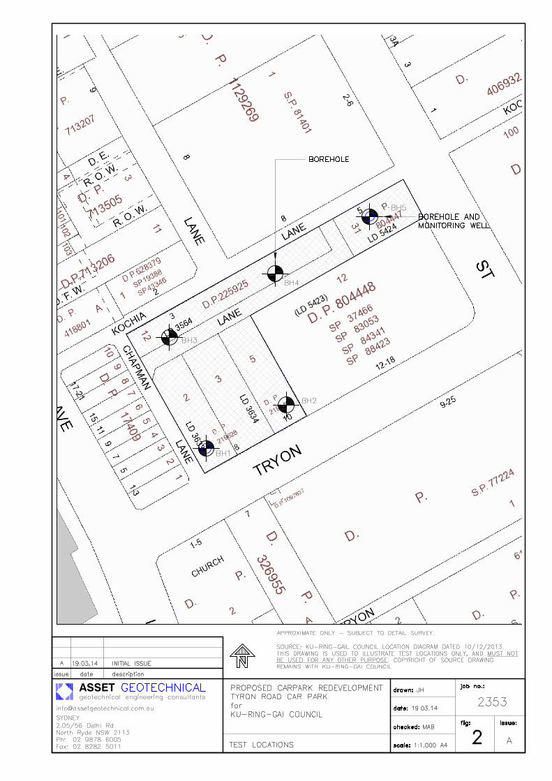
ASSET
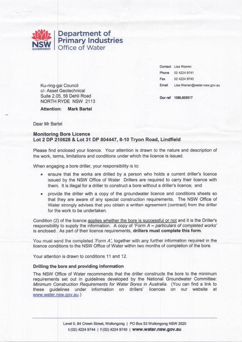

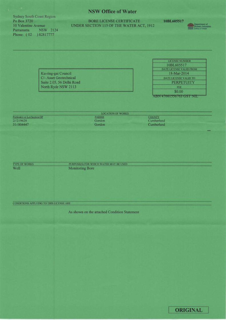
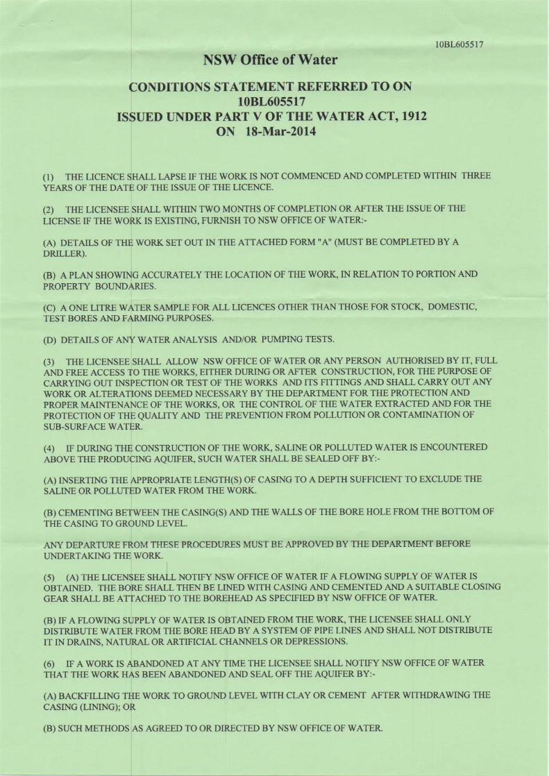


![[SOUND PROOF] DIESEL ENGINE [SOUND PROOF] … · [SOUND PROOF] Minimal Sound Pollution Generator / Welders ABN 14 079 381 481 Importer & Contact Details Email: info@shindaiwa.com.au](https://img.pdfslide.us/doc/110x75/5f3a3ca2584e0e6e146ec988/sound-proof-diesel-engine-sound-proof-sound-proof-minimal-sound-pollution.jpg)