Embed Size (px)
Citation preview
1
Assessment Report on
Feasibility of Tree Support Systems proposed in
Study on Stonewall Trees on Slope no. 11SW-A/R577
Bonham Road, Hong Kong
1. Background
1.1 Highways Department (HyD) is responsible for maintenance of vegetation growing on registered
slopes (including stonewalls) belong to HyD. Some of these stone walls have trees growing
directly on them, and may create risks to nearby residents or road users. In the case of slope no.
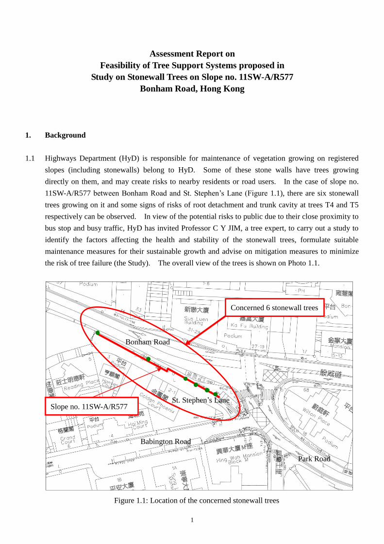
11SW-A/R577 between Bonham Road and St. Stephen’s Lane (Figure 1.1), there are six stonewall
trees growing on it and some signs of risks of root detachment and trunk cavity at trees T4 and T5
respectively can be observed. In view of the potential risks to public due to their close proximity to
bus stop and busy traffic, HyD has invited Professor C Y JIM, a tree expert, to carry out a study to
identify the factors affecting the health and stability of the stonewall trees, formulate suitable
maintenance measures for their sustainable growth and advise on mitigation measures to minimize
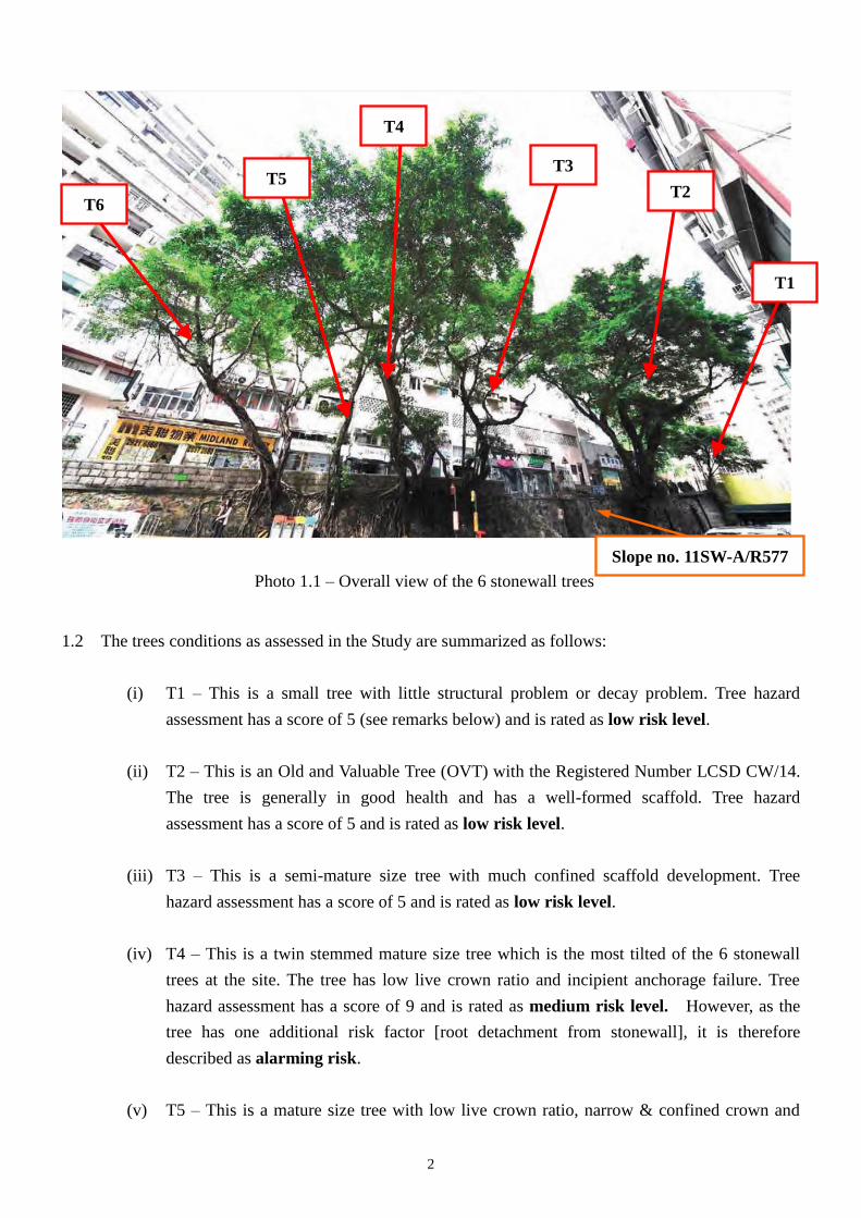
the risk of tree failure (the Study). The overall view of the trees is shown on Photo 1.1.
Figure 1.1: Location of the concerned stonewall trees
Bonham Road
St. Stephen’s Lane
Babington Road
Path Park Road
Concerned 6 stonewall trees
Slope no. 11SW-A/R577
2
1.2 The trees conditions as assessed in the Study are summarized as follows:
(i) T1 – This is a small tree with little structural problem or decay problem. Tree hazard
assessment has a score of 5 (see remarks below) and is rated as low risk level.
(ii) T2 – This is an Old and Valuable Tree (OVT) with the Registered Number LCSD CW/14.
The tree is generally in good health and has a well-formed scaffold. Tree hazard
assessment has a score of 5 and is rated as low risk level.
(iii) T3 – This is a semi-mature size tree with much confined scaffold development. Tree
hazard assessment has a score of 5 and is rated as low risk level.
(iv) T4 – This is a twin stemmed mature size tree which is the most tilted of the 6 stonewall
trees at the site. The tree has low live crown ratio and incipient anchorage failure. Tree
hazard assessment has a score of 9 and is rated as medium risk level. However, as the
tree has one additional risk factor [root detachment from stonewall], it is therefore
described as alarming risk.
(v) T5 – This is a mature size tree with low live crown ratio, narrow & confined crown and
Photo 1.1 – Overall view of the 6 stonewall trees
Slope no. 11SW-A/R577
T6
T4
T5 T3
T2
T1
3
large cavity with decay at the trunk base. Tree hazard assessment has a score of 8 and is
rated as medium risk level. However, as the tree has one additional risk factor [large
trunk base cavity], it is therefore described as alarming risk.
(vi) T6 – This is a twin stemmed mature size tree with heavy lean, asymmetrical crown. Tree
hazard assessment has a score of 5 and is rated as low risk level.
Remarks: Risk score ranges from 3 – 12, from very low risk (score = 3) to high risk (score = 10-12)
2. Deliberation on the proposed methods for supporting the concerned trees
2.1 As mentioned in paragraph 1.2 above, two of the stonewall trees, T4 and T5 are identified in the
Study as having alarming risks. Four methods, namely Methods A to D are proposed in Professor
JIM's study report to support the trees. Three other methods namely Methods E to G have also
been included as alternatives for exploration in this report. The seven proposed methods for
supporting the two concerned trees T4 and T5 are listed below and are examined in details in the
ensuing paragraphs.
(a) Method A: Cables anchor on structural member of a nearby building at St. Stephen’s Lane
(b) Method B: Cables tie-in on steel frame to be anchored at St. Stephen’s Lane
(c) Method C: Installation of supporting frame beneath the trees with supports at stonewall and
Bonham Road pavement
(d) Method D: Cables anchor at the crest of stonewall
(e) Method E: Steel post support at Bonham Road southern footpath
(f) Method F: To cover the bus stop and the section of footpath underneath the two concerned
trees T4 and T5
(g) Method G: Support by structural steel frame from opposite footpath at Bonham Road
2.2 Even though tree roots are currently providing resisting moment and support for the trees, we
observe that there is tree root detachment for tree T4 and the situation may get worse. Therefore,
in carrying out the following structural assessments, we will adopt a more prudent approach by
assuming that the toppling moment due to dead weight of the trees and wind load is to be wholly
resisted by the external supporting system. (i.e. the capacity of the tree roots in holding the trees is
ignored.)
4
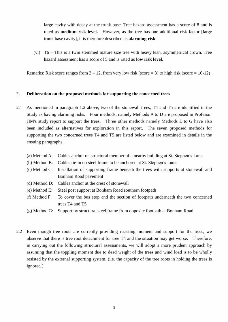
2.3 Method A: Cables anchor on structural member of a nearby building at St. Stephen’s Lane
2.3.1 Method A is considered infeasible for the following reasons:
(i) There are no statutory powers for government authorities including HyD to anchor the
cable system on private structure/building. The general view of nearby building is shown
on Photo 2.1. As the building facade does not belong to individual owner, consents from
owners’ incorporation or all building owners are required. However, there is no incentive
for the building owners to agree the installation of cables on their building. Furthermore,
as extra loading due to cable anchorage will be applied on the building, the liability and
maintenance issues are difficult to be resolved. The works will also affect and limit
future maintenance of building facade and redevelopment of the building.
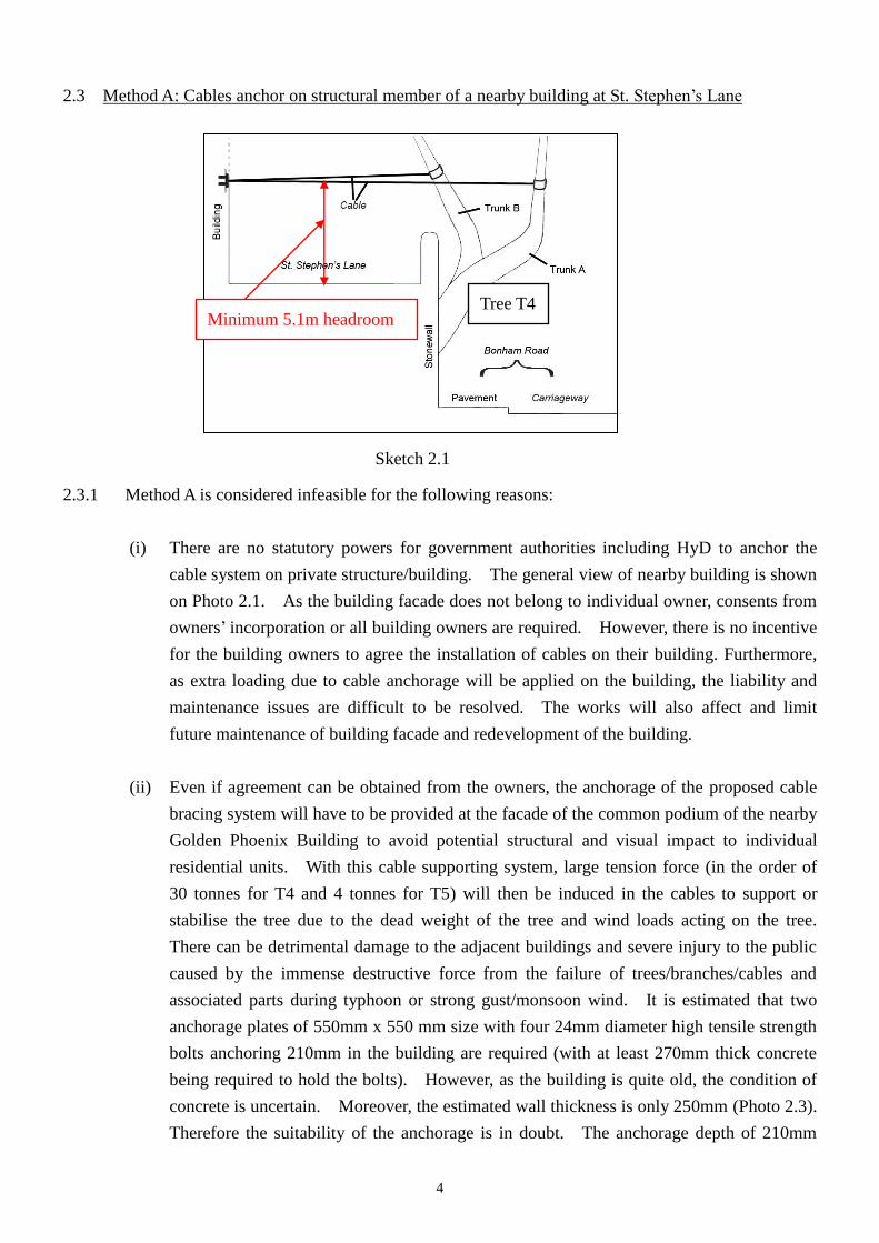
(ii) Even if agreement can be obtained from the owners, the anchorage of the proposed cable
bracing system will have to be provided at the facade of the common podium of the nearby
Golden Phoenix Building to avoid potential structural and visual impact to individual
residential units. With this cable supporting system, large tension force (in the order of
30 tonnes for T4 and 4 tonnes for T5) will then be induced in the cables to support or
stabilise the tree due to the dead weight of the tree and wind loads acting on the tree.
There can be detrimental damage to the adjacent buildings and severe injury to the public
caused by the immense destructive force from the failure of trees/branches/cables and
associated parts during typhoon or strong gust/monsoon wind. It is estimated that two
anchorage plates of 550mm x 550 mm size with four 24mm diameter high tensile strength
bolts anchoring 210mm in the building are required (with at least 270mm thick concrete
being required to hold the bolts). However, as the building is quite old, the condition of
concrete is uncertain. Moreover, the estimated wall thickness is only 250mm (Photo 2.3).
Therefore the suitability of the anchorage is in doubt. The anchorage depth of 210mm
Sketch 2.1
Minimum 5.1m headroom Tree T4
5
would also affect the existing reinforcements inside structural members of the building.
(iii) As a minimum headroom1 of 5.1m has to be maintained at St. Stephen’s Lane for
vehicular traffic, the cables should be mounted at a high position of the tree where the tree
branches may not be strong enough to take the high tension forces. (Photo 2.2)
(iv) The structural stability of the building will be affected due to the extra loading from the
cable system which has not been allowed for in the original design of the building. The
stability of the building is required to be reassessed and strengthening works on the
building will probably be required. Submission to Buildings Department for their
approval is also required for the proposed works and it will take considerable time for the
required processes while the public is being exposed to the risk of tree failure.
1 Transport Planning and Design Manual Volume 2 Chapter 3 Paragraph 3.5.1.3
Photo 2.1 – General view of nearby building
Proposed cables
Photo 2.2 – Proposed cables anchor on the nearby building
6
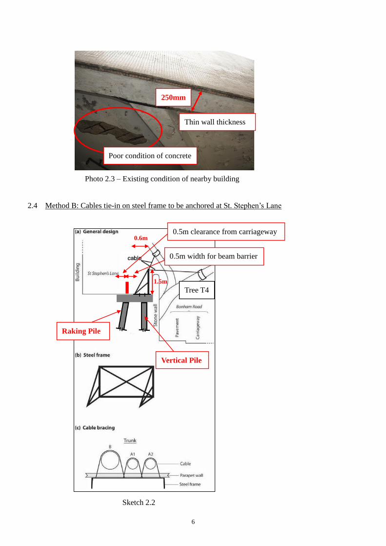
2.4 Method B: Cables tie-in on steel frame to be anchored at St. Stephen’s Lane
Poor condition of concrete
Thin wall thickness
Photo 2.3 – Existing condition of nearby building
250mm
Sketch 2.2
1.5m
0.6m
Vertical Pile
Raking Pile
Tree T4
0.5m clearance from carriageway
0.5m width for beam barrier
7
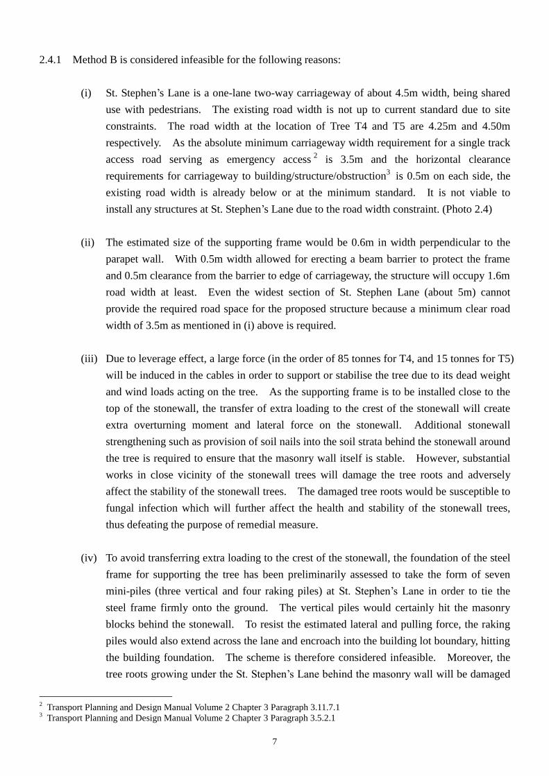
2.4.1 Method B is considered infeasible for the following reasons:
(i) St. Stephen’s Lane is a one-lane two-way carriageway of about 4.5m width, being shared
use with pedestrians. The existing road width is not up to current standard due to site
constraints. The road width at the location of Tree T4 and T5 are 4.25m and 4.50m
respectively. As the absolute minimum carriageway width requirement for a single track
access road serving as emergency access2
is 3.5m and the horizontal clearance
requirements for carriageway to building/structure/obstruction3 is 0.5m on each side, the
existing road width is already below or at the minimum standard. It is not viable to
install any structures at St. Stephen’s Lane due to the road width constraint. (Photo 2.4)
(ii) The estimated size of the supporting frame would be 0.6m in width perpendicular to the
parapet wall. With 0.5m width allowed for erecting a beam barrier to protect the frame
and 0.5m clearance from the barrier to edge of carriageway, the structure will occupy 1.6m
road width at least. Even the widest section of St. Stephen Lane (about 5m) cannot
provide the required road space for the proposed structure because a minimum clear road
width of 3.5m as mentioned in (i) above is required.
(iii) Due to leverage effect, a large force (in the order of 85 tonnes for T4, and 15 tonnes for T5)
will be induced in the cables in order to support or stabilise the tree due to its dead weight
and wind loads acting on the tree. As the supporting frame is to be installed close to the
top of the stonewall, the transfer of extra loading to the crest of the stonewall will create
extra overturning moment and lateral force on the stonewall. Additional stonewall
strengthening such as provision of soil nails into the soil strata behind the stonewall around
the tree is required to ensure that the masonry wall itself is stable. However, substantial
works in close vicinity of the stonewall trees will damage the tree roots and adversely
affect the stability of the stonewall trees. The damaged tree roots would be susceptible to
fungal infection which will further affect the health and stability of the stonewall trees,
thus defeating the purpose of remedial measure.
(iv) To avoid transferring extra loading to the crest of the stonewall, the foundation of the steel
frame for supporting the tree has been preliminarily assessed to take the form of seven
mini-piles (three vertical and four raking piles) at St. Stephen’s Lane in order to tie the
steel frame firmly onto the ground. The vertical piles would certainly hit the masonry
blocks behind the stonewall. To resist the estimated lateral and pulling force, the raking
piles would also extend across the lane and encroach into the building lot boundary, hitting
the building foundation. The scheme is therefore considered infeasible. Moreover, the
tree roots growing under the St. Stephen’s Lane behind the masonry wall will be damaged
2 Transport Planning and Design Manual Volume 2 Chapter 3 Paragraph 3.11.7.1
3 Transport Planning and Design Manual Volume 2 Chapter 3 Paragraph 3.5.2.1
8
and the masonry wall structures will also be adversely affected due to the piling works.
(v) In addition, according to the utility records, there are at least two numbers of underground
electricity cables located at the St. Stephen’s Lane. Underground utility diversion will
result in closure of the whole lane for a long period. Together with the supporting frame
construction works, St. Stephen Lane will have to be closed for prolonged period which is
unacceptable as the lane serves as emergency vehicular access to adjacent buildings.
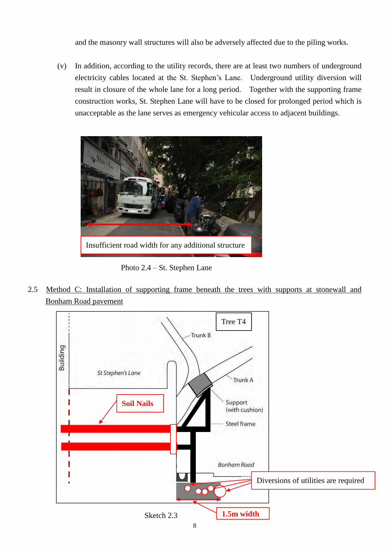
2.5 Method C: Installation of supporting frame beneath the trees with supports at stonewall and
Bonham Road pavement
Insufficient road width for any additional structure
Photo 2.4 – St. Stephen Lane
Tree T4
Sketch 2.3
Soil Nails
1.5m width
Diversions of utilities are required
9
2.5.1 Method C is considered infeasible for the following reasons:
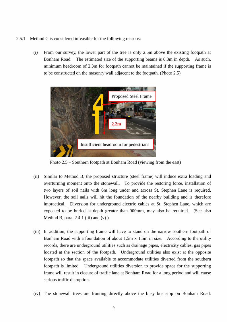
(i) From our survey, the lower part of the tree is only 2.5m above the existing footpath at
Bonham Road. The estimated size of the supporting beams is 0.3m in depth. As such,
minimum headroom of 2.3m for footpath cannot be maintained if the supporting frame is
to be constructed on the masonry wall adjacent to the footpath. (Photo 2.5)
(ii) Similar to Method B, the proposed structure (steel frame) will induce extra loading and
overturning moment onto the stonewall. To provide the restoring force, installation of
two layers of soil nails with 6m long under and across St. Stephen Lane is required.
However, the soil nails will hit the foundation of the nearby building and is therefore
impractical. Diversion for underground electric cables at St. Stephen Lane, which are
expected to be buried at depth greater than 900mm, may also be required. (See also
Method B, para. 2.4.1 (iii) and (v).)
(iii) In addition, the supporting frame will have to stand on the narrow southern footpath of
Bonham Road with a foundation of about 1.5m x 1.5m in size. According to the utility
records, there are underground utilities such as drainage pipes, electricity cables, gas pipes
located at the section of the footpath. Underground utilities also exist at the opposite
footpath so that the space available to accommodate utilities diverted from the southern
footpath is limited. Underground utilities diversion to provide space for the supporting
frame will result in closure of traffic lane at Bonham Road for a long period and will cause
serious traffic disruption.
(iv) The stonewall trees are fronting directly above the busy bus stop on Bonham Road.
Photo 2.5 – Southern footpath at Bonham Road (viewing from the east)
Insufficient headroom for pedestrians
Proposed Steel Frame
2.2m
10
Relocation of bus stop and cancellation of bus lay-by to free more space for the proposed
works has also been considered. However, as advised by Transport Department (TD),
there is no alternative lay-by along Bonham Road (westbound) for the bus stop relocation.
Without the bus lay-by, on-street picking-up/dropping-off of passengers on Bonham Road
will severely disrupt traffic flow in the area. TD and the locals will not support the
proposal of relocating the bus stop.
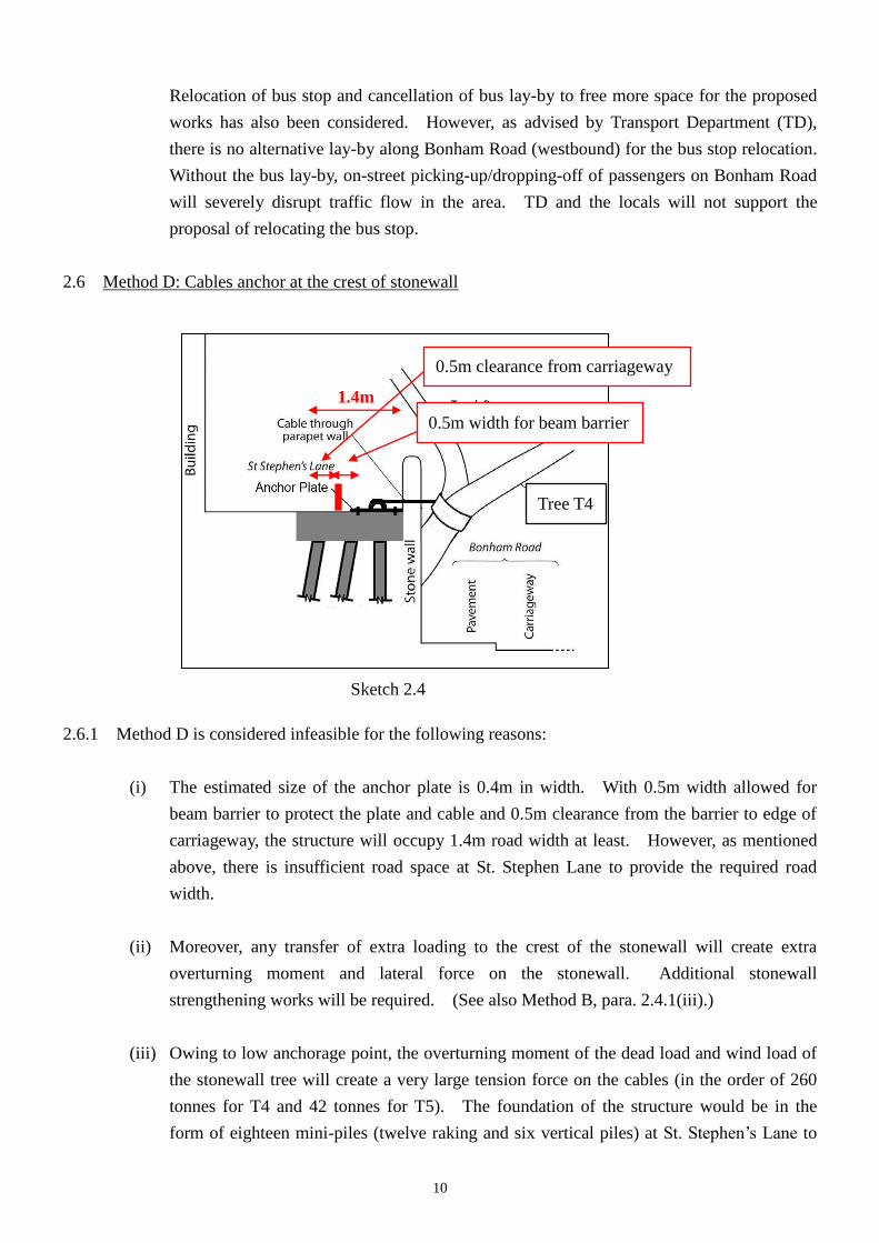
2.6 Method D: Cables anchor at the crest of stonewall
2.6.1 Method D is considered infeasible for the following reasons:
(i) The estimated size of the anchor plate is 0.4m in width. With 0.5m width allowed for
beam barrier to protect the plate and cable and 0.5m clearance from the barrier to edge of
carriageway, the structure will occupy 1.4m road width at least. However, as mentioned
above, there is insufficient road space at St. Stephen Lane to provide the required road
width.
(ii) Moreover, any transfer of extra loading to the crest of the stonewall will create extra
overturning moment and lateral force on the stonewall. Additional stonewall
strengthening works will be required. (See also Method B, para. 2.4.1(iii).)
(iii) Owing to low anchorage point, the overturning moment of the dead load and wind load of
the stonewall tree will create a very large tension force on the cables (in the order of 260
tonnes for T4 and 42 tonnes for T5). The foundation of the structure would be in the
form of eighteen mini-piles (twelve raking and six vertical piles) at St. Stephen’s Lane to
Sketch 2.4
Tree T4
0.5m clearance from carriageway
0.5m width for beam barrier
1.4m
11
provide the required lateral resistance. The raking piles would hit the foundation of the
nearby building and make the scheme infeasible. (See also Method B, para. 2.4.1(iv).)
(iv) In addition, diversion for underground electric cables at St. Stephen Lane is required.
(See also Method B, para. 2.4.1(v).)
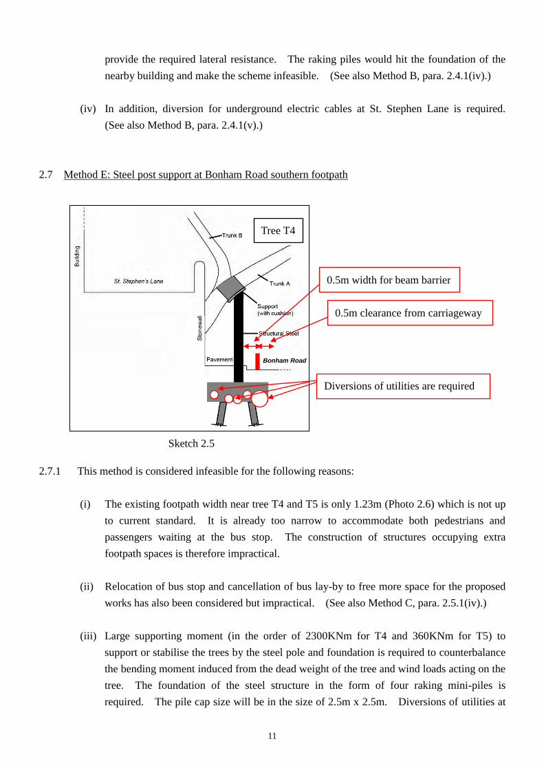
2.7 Method E: Steel post support at Bonham Road southern footpath
2.7.1 This method is considered infeasible for the following reasons:
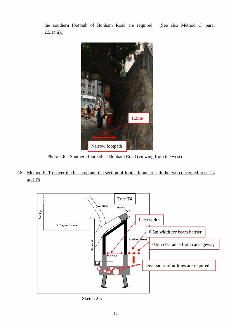
(i) The existing footpath width near tree T4 and T5 is only 1.23m (Photo 2.6) which is not up
to current standard. It is already too narrow to accommodate both pedestrians and
passengers waiting at the bus stop. The construction of structures occupying extra
footpath spaces is therefore impractical.
(ii) Relocation of bus stop and cancellation of bus lay-by to free more space for the proposed
works has also been considered but impractical. (See also Method C, para. 2.5.1(iv).)
(iii) Large supporting moment (in the order of 2300KNm for T4 and 360KNm for T5) to
support or stabilise the trees by the steel pole and foundation is required to counterbalance
the bending moment induced from the dead weight of the tree and wind loads acting on the
tree. The foundation of the steel structure in the form of four raking mini-piles is
required. The pile cap size will be in the size of 2.5m x 2.5m. Diversions of utilities at
Sketch 2.5
Diversions of utilities are required
0.5m clearance from carriageway
0.5m width for beam barrier
Tree T4
Bonham Road
12
the southern footpath of Bonham Road are required. (See also Method C, para.
2.5.1(iii).)
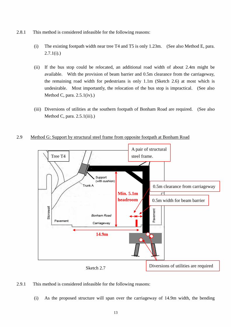
2.8 Method F: To cover the bus stop and the section of footpath underneath the two concerned trees T4
and T5
Photo 2.6 – Southern footpath at Bonham Road (viewing from the west)
Narrow footpath
1.23m
Sketch 2.6
Diversions of utilities are required
1.1m width
0.5m clearance from carriageway
0.5m width for beam barrier
Tree T4
Bonham Road
13
2.8.1 This method is considered infeasible for the following reasons:
(i) The existing footpath width near tree T4 and T5 is only 1.23m. (See also Method E, para.
2.7.1(i).)
(ii) If the bus stop could be relocated, an additional road width of about 2.4m might be
available. With the provision of beam barrier and 0.5m clearance from the carriageway,
the remaining road width for pedestrians is only 1.1m (Sketch 2.6) at most which is
undesirable. Most importantly, the relocation of the bus stop is impractical. (See also
Method C, para. 2.5.1(iv).)
(iii) Diversions of utilities at the southern footpath of Bonham Road are required. (See also
Method C, para. 2.5.1(iii).)
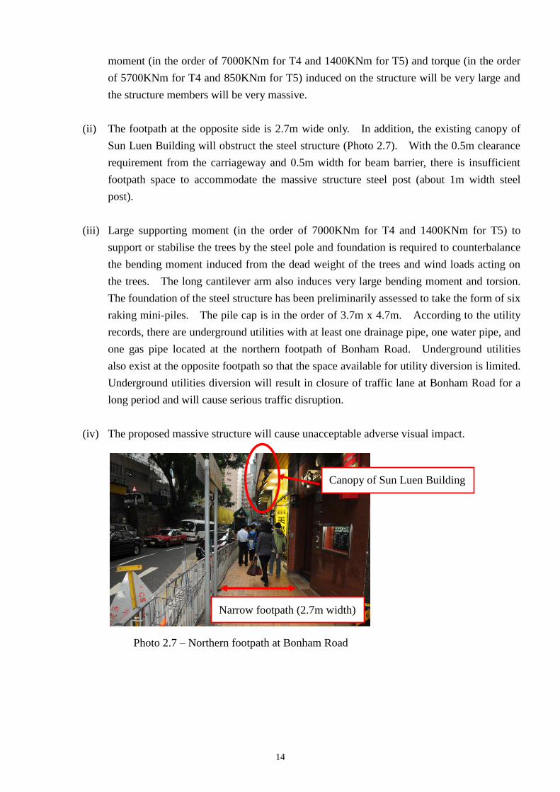
2.9 Method G: Support by structural steel frame from opposite footpath at Bonham Road
2.9.1 This method is considered infeasible for the following reasons:
(i) As the proposed structure will span over the carriageway of 14.9m width, the bending
Sketch 2.7 Diversions of utilities are required
0.5m clearance from carriageway
A pair of structural
steel frame. Tree T4
14.9m
0.5m width for beam barrier
Min. 5.1m
headroom
14
moment (in the order of 7000KNm for T4 and 1400KNm for T5) and torque (in the order
of 5700KNm for T4 and 850KNm for T5) induced on the structure will be very large and
the structure members will be very massive.
(ii) The footpath at the opposite side is 2.7m wide only. In addition, the existing canopy of
Sun Luen Building will obstruct the steel structure (Photo 2.7). With the 0.5m clearance
requirement from the carriageway and 0.5m width for beam barrier, there is insufficient
footpath space to accommodate the massive structure steel post (about 1m width steel
post).
(iii) Large supporting moment (in the order of 7000KNm for T4 and 1400KNm for T5) to
support or stabilise the trees by the steel pole and foundation is required to counterbalance
the bending moment induced from the dead weight of the trees and wind loads acting on
the trees. The long cantilever arm also induces very large bending moment and torsion.
The foundation of the steel structure has been preliminarily assessed to take the form of six
raking mini-piles. The pile cap is in the order of 3.7m x 4.7m. According to the utility
records, there are underground utilities with at least one drainage pipe, one water pipe, and
one gas pipe located at the northern footpath of Bonham Road. Underground utilities
also exist at the opposite footpath so that the space available for utility diversion is limited.
Underground utilities diversion will result in closure of traffic lane at Bonham Road for a
long period and will cause serious traffic disruption.
(iv) The proposed massive structure will cause unacceptable adverse visual impact.
Narrow footpath (2.7m width)
Canopy of Sun Luen Building
Photo 2.7 – Northern footpath at Bonham Road
15
3. Conclusion
3.1 All probable options, in particular those recommended in Prof. JIM’s study, for preservation of the
concerned trees T4 and T5 have been thoroughly looked into. However, owing to the extremely
constrained site conditions, there is no viable scheme for supporting the concerned trees T4 and T5.
3.2 Other abatement measures including (i) restricting access/cordon off the area within the possible
tree fall zone; (ii) removal or relocating the potential target/objects that may be hit by the fallen
trees; and (iii) pruning have also been considered. The first two abatement measures are
undoubtedly not feasible in view of the busy vehicular and pedestrian traffic which cannot be
cordoned off and the existence of bus stop, residential buildings and shops which cannot be
relocated. Besides, the existing live crown ratios of the concerned trees T4 and T5 are already low
and very low respectively providing little scope for further pruning. More fundamentally, such
pruning which may only provide limited reduction in dead weight and wind load of the trees cannot
fundamentally address the significant risks posed to public as alarmed by the sign of root
detachment of T4 and the large trunk cavity of T5.
3.3 In view of the fact that the alarming risk of the trees, which would endanger pedestrians and traffic
on Bonham Road and nearby properties, cannot be mitigated, the removal of the problematic trees is
the last option and inevitable. This could also help to alleviate the pressures on the stonewall and
would therefore in a way help to maintain its stability for the remaining stonewall trees.
4. Recommendation
4.1 In view of the significant risk to public safety and in accordance with the general advice
promulgated by DEVB4, the trees T4 and T5 are recommended to be felled as soon as possible
before the onset of typhoon season in May this year, as well as to follow the requirement of prompt
action for the completion of necessary action to remove the identified risks of problematic trees.
Highways Department
April 2013
4 Secretary for Development’s memo of 8 April 2013 referenced DEVB(GLTM) 200/2/3