Embed Size (px)
Citation preview
ISIJ International, Vol. 30 (1990), No. lO, pp. 854--861
Assessmentof Remaining Life of
Miniature Creep Rupture Test
Fossil PowerPlant Parts by meansof a
YOShikuni KADOYA,Toru GOTO,ShingO DATE,TakayOShiYAMAUCHl,TOmikaneSAIDAand Tetsuro
SADA1)
TakasagoResearch &DevelopmentCenter, Mitsubishi Heavy Industries, Ltd., Shinhama, Arai-cho, Takasago, Hyogo-ken, 676 Japan.
1)KobeShipyard &Machinery Works, Mitsubishi Heavy Industries, Ltd., Wadasaki-cho, Hyogo-ku, Kobe, Hyogo-ken, 652 Japan.
(Received on December28, 1989, accepted in the final form on April 20, 1990)
In order to validate a procedure for creep rupture tests using miniature specimens, a sampling technique and a methodof making the miniature specimenswere investigated. Finally, the use of the iso-stress creep rupture test on the minia-
ture specimens to predict the remaining creep life of Cr-Mo-V, 21/4Cr-Mo and 11/4-1/2Mo steel wasexamined.
Thecreep curve, rupture life and ductility of the miniature specimenstested in argon were similar to those of conven-tional sized specimensin air. Thefracture modeof the miniature specimenswasalso consistent with that of conventional
sized specimens.
Ona graph showing tremperature Tvs. Iog time to rupture t., the creep rupture data were represented with an iso-stress
line, respectively. Each iso-stress line shifted parallel with the stress level.
Moreover, the sampling device that wasdeveloped wasapplied to the operating plant components. Sampleshave
been successfully removedfrom it and were obtained without affecting the material properties around the core hole.
KEYWORDS:creep; miniature specimen; stress-rupture test; iso-stress; Iow alloy steels; sampling technique; remaininglife.
1. Introductron
Judging from the recent trend in powerdemand,itis expected that presently operating_ power plants, orso-called aging power plants, in particular, whoseop-erating periods are being extended, will have to bear
even heavier loads than ever before as middle-powerand peak-power supply plants. In addition, these
aging power plants are supposed to carry out theplant life assessment in order to cope with the exten-sion of the period between the two regular mainte-
nance inspections.
Under these circumstances, in order to maintainand operate these aging power plants efriciently,
while ensuring their safety and reliability, the exten-sion of plant life is desired nowmore than ever. Akey ingredient in plant life extension is the remaining-life-assessment technology.
For the remaining-life-assessment, the history-basedcalculation methodhas cometo be widely used. Thismethod, however, often fails to provide suflicient ac-
curacy becauseof the uncertainty of various importantinformation such as operating conditions and materialproperties specific to the component. Further studies
to improve the accuracy andconfldence of remaining-life-assessment need to be made.
To solve this problem, the NonDestructive Evalua-tion (NDE) method is considered effective. This
methodis able to assess the remaining life by directly
observing or inspecting the deterioration anddamageof the material without being destructive to it. A
variety of the NDEmethods, therefore, have been de-
veloped and are being applied actively to operatingplant components.1,2)
A destructive test done by sampling is another
method of assessment. This method is somewhatadvantageous in that the remainiig life can be direct-
ly obtained by actually rupturmg the specrmensThrough the development of a sampling technique
and a miniaturization technique, this method is ex-pected to greatly supplement the NDEmethod in
estimates of remaining life. For example, application
of this method to boiler componentsis nowbeing in-
vestigated,3-5) because of' the easiness of sampling andrecovering such as weld repair.
Weare nowexamining to apply this methodto the
materials of turbine componentsas well as boiler com-po_nents.6) So far, however, further development of
the sampling technique as well as accumulation of
various data is necessary before this method can beefficiently applied to operating plant components.
This study aims to investigate a methodof asscssing
the remaining life of' materials used ih fossil powerplant componentsby meansof a miniature creep rup-ture test. Asampling device wasdeveloped and data
was prepared covering a long time period. The va-lidity of this methodis discussed.
2. Materials and Experimental Procedure
2. I .Materials
The materials were Cr-Mo-V steel, 21/4Cr-Mo
854 C1990 ISIT
ISIJ International, Vol. 30 (1990), No. lO
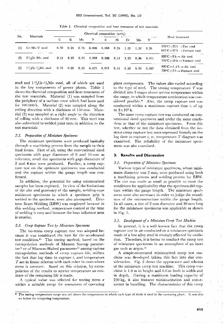
Table 1. Chemical composition and heat treatment of test materials.
No. MaterialsChemical composition (wto/o)
C Si Mn s Ni Mo VCrHeat treatment
(1) Cr-Mo-V steel O30 O25 O75 O008 O008 O35 1 23 1.20 O.26970'C x22h- Fan cool
665'C x67 h~Furnace cool
(2) 21/4Cr-Mo steel O12 0.23 0.55 0.009 0.008 O. 14 2.22 O96 O. Ol 1920"Cx 8h- Air cool
705'CX15 h- Furnace cool
(3) 11/ Cr /Mosteel O10 O60 O55 0.015 0.013 O14 1 20 O59 0.007920'CX1.5h -Air cool
720'C > 3h- Furnace cool
steel and 11/4Cr-1/2Mo steel, all of which are usedin the key components of power plants. Table 1showsthe chemical composition and heat treatment ofthe test materials. Material (1) was sampled fromthe periphery of a turbine rotor which hadbeenusedfor 100 OOOh. Material (2) was sampled along therolling direction with a thickness of 150 mm. Mate-rial (3) wassampled at a right angle to the directionof rolling with a thickness of 40 mm. This steel wasalso submitted to welded joint tests in addition to thetest materials.
2.2. Preparation of Miniature Specimens
The miniature specimens were produced basically
through a machining process from the sample to their
final forms. First of all, using the conventional sized
specimens with gage diameters of 8 and 10mmasreference, small size specimenswith gagediameters of
2and 4mmwere produced. Further, a creep rup-ture test on the optimumspecimens was conductedand the rupture within the gauge length was con-flrmed.
In addition, the potential for using miniaturizedsamples has beenexplored. Inview of the limitations
of the size and geometry of the sample, welding-typeminiature specimens in which a specimen grip is
welded to the specimen, were also attempted. Elec-
tron BeamWelding (EBW)was employedbecause inthis welding method, temperature control at the timeof welding is easy and because the heat influence areais smaller.
2.3. Creep Rupture Test by Miniature Specimens
The iso-stress creep rupture test was adopted be-
cause it. was considered the best for the acceleratedtest condition.4) This testing method, based on theextrapolation methods of Manson-Succopparame-ter7) or, of Manson-Haferdparameter8) amongvariousextrapolation methods of creep rupture life, utilizes
the fact that log time to rupture t. and temperatureTare in linear relation with each other in cases wherestress is constant. Based on this relation, by extra-polation of the results to service temperature an esti-
mate of the remaining life is made.A typical value was selected for testing stress (1
within a suitable Jfange for assessment of operating
plant components. The values also varied accordingto the type of steel. The testing temperature Twasdivided into 3stages aboveservice temperature withinthe range, in which temperature acceleration wascon-sidered possible.* Also, the creep rupture test wasconducted within a maximurnrupture time t. of upto 3> 103 h.
Thesamecreep rupture test wasconducted on con-ventional sized specimens and under the samecondi-tions as that of thc miniature specimens. Fromthis
test, whether or not the data obtained from the iso-
stress creep rupture test wereexpressed linearly on thelog time to rupture t. vs. temperature Tdiagram wasexamined. The reliability of the miniature speci-
menswas also examined.
3. Results andDiscussion
3. 1. Preparation of Miniature Specimens
Various types of miniature specimens, whosemini-
mumdiameter was 2mm,were produced using botha machining process and welding process by EBW.The size was madeas small as possible to meet theconditions for applicability that the specimendid rup-ture within the gauge length. The miniature speci-
menswere also necessary in order to judge the sound-
ness o_f the microstructure within the gauge length.
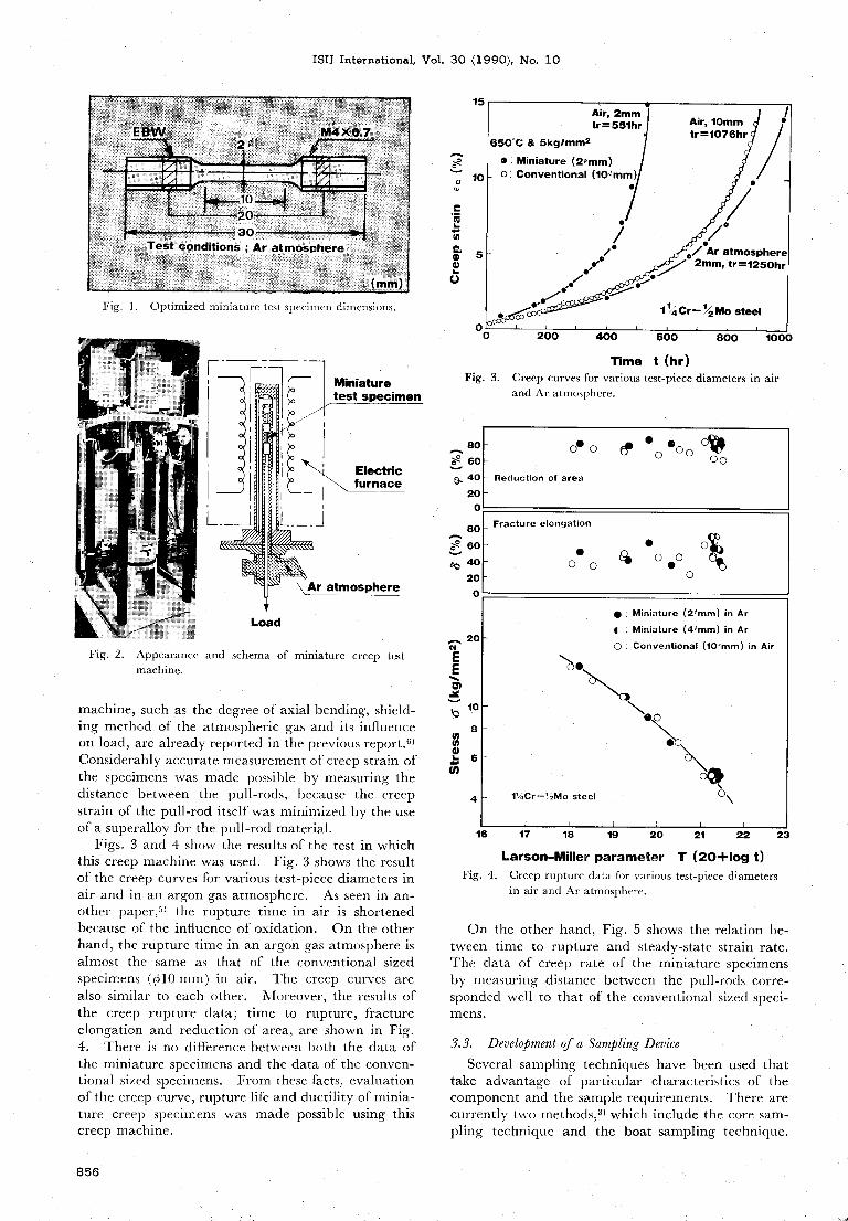
In all cases, a size of 2mmdiameter and 30 mmlongfor the miniature specimenswasapplicable as shownin Fig. l.
3. 2. Developmentof a Miniature Creep Test Machine
In general, it is a well knownfact that the creeprupture test in air conducted on a miniature specimenmadeof' a low alloy steel is strongly affected by oxida-tion. Therefore, it is better to conduct the creep test
of miniature specimens in an atmosphereof an inert
gas such as argon.5)
A simple-structured miniaturized creep test ma-chine was developed taking this fact into due con-sideration. Fig_
. 2shows the appearance and schemaof' the miniature creep test machine. This creep ma-chine is I .8 min height and 0.6 mboth in width andin depth. Having a maximumloading capacity of250 kg, it also features miniaturization and conve-nience in handling. The characteristics of this creep
* The testing temperature range was set above the temperature in which each type of steels is used in the operating plant.
set below the tempering temperature.
It wasalso
855
ISIJ International, Vol. 30 (1990), No. lO
:aLu,
aOOLOFig. l. Optimized miniature test specimen dimensions.
15
10
5
O
Air, 2mmtr =55lhr
650"C&5kglmm2o : Miniature (2~mm)o : Conventional (10cmm)
el'rel
oc~:~e~co
e,
el
,/,
.~lel'
Airl lomm Jtr=1076hr
e
loel~Ar atmosphere2mm,tr=1250hr
1~~ Cr- 112Mosteel
Miniaturetest specimen
\lYr'fEulre:ctric
furnace
Ar atmosphere
O
Fig. 3.
800::~ 60~• 40
20O
80o\e 60
ee 4020O
Fig. 2. Appearancemachine.
and schema of miniature creep test
machine, such as the degree of axial bending, shield-
ing method of the atmosphencgas and its influence
on load, are already reported in the previous report.6)
Considerably accurate measurementof creep strain ofthe specimens was madepossible by measuring thedistance between the pull-rods, bccause the creepstrain of the pull-rod itself was minimized by the useof a superalloy for the pull-rod material.
Figs. 3and 4 show the results of the test in whichthis creep machinewasused. Fig. 3shows the resultof the creep curves for various test-piece diameters inair and in an argon gas atmosphere. As seen in an-other paper,5) the rupture time in air is shortenedbecause of the influence of oxidation. Onthe otherhand, the rupture time in an argon gas atmosphere is
almost the same as that of the conventional sizedspecimens ((J510mm) in air. The creep curves arealso similar to each other. Moreover, the results ofthe creep rupture data; time to rupture, fractureelongation and reduction of area, are shown in Fig.4. There is no difference between I)oth the data ofthe miniature specimens and the data of' the conven-tional sized specimens. Fromthese facts, evaluationof the creep curve, rupture life and ductility of minia-ture creep specimens was madepossible using this
creep machine.
f~ 20
EE\o'~~k:),
IP
u;8oS:6
cb
4
200 400 600 800 1000
Time t (hr)
Creep curves for various tcst-piece diameters in air
and Ar atmosphcre.
oeo ~'oo
eoo Cf~oo
Reduction of area
Fracture elongation
ee
oO~) oo,
'~o
e: Miniature (2#mm)in Ar
1: Miniature (4~mm)in Ar
o: Conventional (10;mm) in Air
O\..
l~;Cr-112Mo steel o\
16
Fig. 4*
17 18 20 23l9 21 22
Larson-Miller parameter T (20+10g t)
Creep rupture data fbr var[ous test-piece diametersin air and Ar atmosphere.
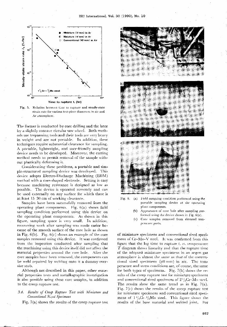
Onthe other hand, Fig. 5 shows the relation be-
tween time to rupture and steady-state strain rate.
The data of creep rate of the miniature specimensby measuring distance between the pull-rods corre-sponded well to that of the conventional sized speci-
mens.
3.3. Developmentof a Sampling Device
Several sampling techniques have been used thattake advantage of particular characteristics of the
componentand the sample requirements. There arecurrently two rnethods,3) which include the core sam-pling technique and the boat sampling technique.
856
ISIJ International, Vol. 30 (1990), No, lO
1(ro
=\
'y'10
1,
f5
l~u,
a,
Ce
u'l 10
)~1;c!a,
u,
lc'3
O : Miniature (2**mm) in ArMiniature (4~mm)in ArConventional (10#mm)in Air
_ 12MOsteet11/4 Cr ll
o\):\
O\a\..,
,.- \~\o'~_"\
Fig. 5.
10' I03 I04102
Time to rupture t, (hr)
Relation between time to rupture and steady-state
strain rate for various tcst-piece diameters in air andAr atmosphere.
The former is conducted by core drilling and the later
by a slightly concavc circular sawwhcc_1. Both meth-ods use trepanning tools and their tools are very hcavyin weight and are not portable. In addition, these
techniques require substantial clearance for sampling.
A portable, Ii~"htweight, and user-friendly samplingdevice needs to be developed. Moreover, the cutting
methodneeds to permit removal of the sample with-
out plastically deforming it.
Consideratin~" these problems, a portable and sim-ple-structured sampling device was developed. Thisdevice adopts Electro-Discharge Machining (EDM)methodwith a core-shaped electrode. Setting is easybecause machining resistance is designed as low aspossible. The device is operated remotely and canbe used externally on any surface for which there is
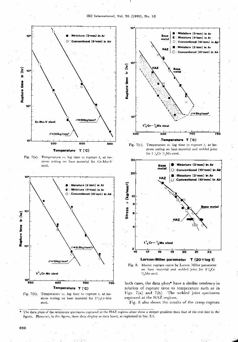
at least 15-30 cmof working clearance.Sampleshave been successfully removedfrom the
operating plant components. Fig. 6~a) shows field
sampling condition performed using this device onthe operating plant components. As shown in this
flgure, sampling space is very small. In addition,recovering work after sampling was madeeasier be-
cause of the smoothsurface of the core hole as shownin Fig. 6(b). Fig. 6(c) showsan example ofthe coresamples removedusing this device. It wasconfirmedfrom the inspection conducted after sampling thatthe machining using this device itself'did not aflbct thematerial properties around the core hole. After the
core samples havc been removed, the componentscanbe weld repaired by welding onto it a dummyover-size stub.
Although not described in this paper, other mate-rial properties tests and metallographic investigationis also possible usin~'_ these core samples, in additionto the creep rupture test.
3.4. Results of Creep Rupture Test z~)ith Miniature andConventional Sized Specimens
Fig. 7(a) shows the results of the creep rupture test
Fig. 6. (*)
(b )(c)
Ficld sampling condition performed using the
portable sampling device at the operatingplant components.Appearanceof core hole after sampling per-formed using the devic-e shownin Fig. 6(a).
Core samples remove.d from elevated tem-perature parts.
of miniature specimens and conventional sized speci-
mensof Cr-Mo-Vsteel. It was confirmed from this
figure that the log time to rupture t. vs. temperatureT diag_ram shows linearity and that the rupture timeof the adopted miniature specimens in an argon gasatmosphere is almost the samcas that of the conven-tional sized specimens (c8 mm)in air. The tem-perature and stress conditions are, of course, the samefor both types of specimens. Fig. 7(b) shows the re-sults of the creep rupture test fbr miniature specimensand conventional sized specimcns of 2l/2Cr-Mo steel.
The results show the same trend as in Fig. 7(a).
Fig. 7(c) shows the results of the creep rupture testfor miniature specimens and conventional sized speci-
mensof I l/4Cr1/2Mo steel. This figure shows theresults oi' the base material and welded joint. For
,
i;
857
ISIJ International, Vol. 30 (1990), No. lO
104
~' I03
J~
oE~5
2a~
102
101
o
\o
8
e:O:
Cr-Mo-Vsteel :
(;=30kg/mm2
Miniature (2cmm)in Ar
Conventional (8cmm) in Air
g
d=20kglmm2
e\
550 600 650
Temperature T ('O
Temperature vs. Iog time to rupture tT at iso-
stress testing on basc material for Cr-Mo-Vsteel.
b,
OE~:
OL:a:,'E
104
103
102
\\
e : Miniature (2~mm)in ArBase O : Miniature (4#mm)in Armetal
O: COnventional (10~mm)in Air
I : Miniature (2cmm)in ArHAZ[] : COnventional (10~mm)in Air
a
HAZ Base
~': ~:
(\~~~ta:
~
'
'~l" :'/S,
_~ \\ \I~ ~' ~~~:_' 8\~-":' ;11
~'~~~I
_ o \~.
1;j(14 Cr- 112Mosteel
600
Fig.
104
7(a).
ldiniature (2cmm)in ArMiniature (4~mm)in ArConventional (10~mm)in Air
,~EE~,,
J,
~bcou'
S~co
Fig.
30
- I03
,
d,
E~:
oL:
a:,E I02
e
7(c).
101
e:o:o:
e
c
C=13kglmm2
(r =8.5kglmmeo
21./4Cr-Mo steel
8
550
65O 700 750
Temperature T ('OTemperature vs. Iog time to rupture tT at iso-
stress testing on base material and welded _joint
for 11/4Cr1j2Mo steel.
20
IO
8
6
4
2
Base e : Miniature (2~mm)in Armetal O: Conventional (10~mm)in Air
I : Miniature C2~mm)in ArHAZ [] : Convenlional (10~mm)in Air~,
[~]~(:1!
"\C]
~]
lr• Basemetalti
HAJ~/1:1'~
1/4 Cr- 112Mosteel
C~CI
600 650 700Temperature T ("O
Temperature vs. Iog time to rupture tT at iso-
stress testing on base material for 21/4Cr-Mosteel.
16
Fig. 8.
17 18 I9 2120 22
Larson-Miller parameter T (20+10g t)
Master ruptl're curve by Larson-Miller parameteron base material and welded joint for 11/4Cr-
1!2Mosteel.
Fig. 7(b).
both cases, the data plots* have a similar tendency in
relation of rupture time to temperature such as in
Figs. 7(a) and 7(b). The welded .joint specimensruptured at the HAZregions.
Fig. 8 also shows the results of the creep rupture
* Thedata plots of the miniature specimens ruptured at the HAZregions alone showa steeper gradient than that of the real line in the
figure. However, in this figure, these data display as data band, as explained in Sec. 3.5.
858
ISIJ International, Vol. 30 (1990), No. lO
test fbr 11/4Cr-i/2Mo steel. The test was conductedfor various stresses and the data were arranged usingthe Larson-Miller parameter. For both cases of thebase material and welded joint, there is no differencebetween both the results of the miniature specimensand of the conventional sized specimens. The scat-tered data of miniature specimens of a welded joint((T=5 kg/mm2) correspond to the data shownby theband in Fig. 7(c).
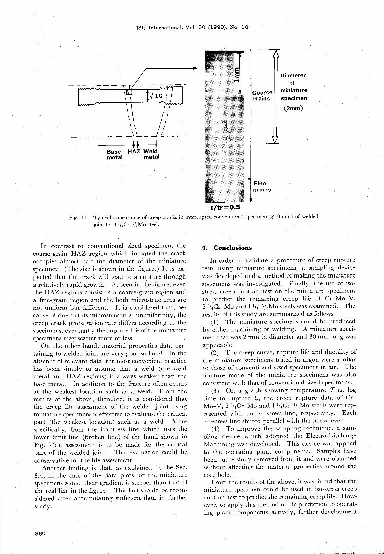
Fig. 9 shows the typical micrographs of a longi-tudinal cross section of' typical ruptured specimens.Figs. 9(a) and 9(b) are the cases of 21/4Cr-Mo steel
in comparison with the conventional sized specimen(clO mm)and the miniature specimen (c2 mm)rup-tured under the same test condition. It was foundthat the fracture modeof both specimens were the
sameand showed transgranular fracture. Fig. 9(c)shows the case of welded joint for 11/4Cr-1/2Mosteel. It was found that the fracture modewas anintergranular fracture with cavitation at the HAZregions. Although the fi~"urcs are not shr_)wn in this
paper, similarly, in the case of' base material of Cr-Mo-Vsteel and 1Ij4Cr-1/2Mo steel, the miniaturespecimen and the conventional sized specimen cor-respond well with each other.
Onthe other hand, these data have generally beenlimited to test times oi' Iess than 3X10³ h. Oucstionshave also remained as to the effect of creep ductility
and heat to heat variations on the validity of the iso-
stress creep rupture test. To investigate the pos-sibility of linearity on the log time to rupture tr vs.
temperature T diagram when thc iso-stress test is
conducted for longer periods, the samerelation suchas in Fig. 7was confirmed using the creep data sheetof NRIM9-11) of the samesteels. This attempt ap-pears to be very uscful because the data includes creeprupture tests up to 8xl04 h, at the longest. Al-though the flgures are not sho_wnin this paper, it wasconfirmed that, within limits of scatter, the iso-stress
lines (the lines which connect the data under the samestress condition on the log time to rupture t. vs. tem-
perature T diagram) were straight and in parallelwith o_ne another depending on the stress level.
3.5. Remaining Creep Llfe of a Welded Joint UsingMiniature Specimens
In the scatter band as shownin Fig_.
7(c), the dataplots of the miniature specimensruptured at the HAZreg_ ions scattered moreor less in comparison vvith thatof' the conventional sized specimens. Oneof the rea-sons for this is considered to be the difference in creeprupture characteristics of the welded joint, as ex-plained below.
C'.enerally, the welded joint is a composite materialconsisting of the base metal, HAZregions and theweld metal. Mechanical properties can vary fromzone to zone. So, its creep rupture characteristictends to showan unpredictable mannerin comparisonwith that of the base material. Nevertheless, in gen-eral, it is also a fact that in most of the welded joint,
creep cracking is initiated at the HAZregions andthat this crack growth leads to rupture.12) In this
study, creep rupture in welded joint has also beenobserved at the HAZregions described in Sec. 3.4.
Fig. IOshowsthe typical appearanceofcreep cracksat the HAZregions in interrupte.d specimcns for aconventional sized specimen (clOmm) of 11/4Cr-1/2Mo steel (t/t,=approximately 0.5, where t is aninterrupted test period). In this figure, it is rec-ogni7,cd that a creep crack initiates at the coarse-grain HAZregion. The figure showsan area abouthalf the size of the diameter of the conventional sizedspecimen. Theremaining half is occupied mostly bythe fine-grain HAZreg_ ion with no initiation of' cavityand any other creep cracks. It is thought tha,t the
creep rupture life is dominated by the propagation ofthe crack, which, initiating in the coarse-grain HAZreg_ ion, finally reaches the fine-grain HAZregion.Thus, it seemsthat, as in the case of a low ductilitymaterial of intergranular fracture such as the HAZregions, crack initiation and propagation are the mainprocess of creep rupture.
Basemetal
HAZ Weldmetal
Fig.
(a) Conventional specirnen (c 10 mm)for 21/4Cr-Mo steel
(b) Miniature specimen (c2 mm)for 21/4Cr-Mo steel
(c) Miniaiure specimen (~;2 mm)of weldcd .joint consisting of the base metal, HAZand weld metal for
11/4Cr-1/2Mo steel
9. Typical micrograph of creep ruptured specimen.
859
ISIJ International, Vol. 30 (1990), No, lO
LlIt c10
11Il
It /lLI ll\\ ll\L ll
--,\ __JL___
Fig.
Base HAZWeldmetal metal
t/tr= 0.5
Coarsegrains
Finegrains
Diameterof
miniature
speamen(2mm)
10. Typical appearanceof creep cracks in interruptcd conventional specimen ((,~lO mm)of welded
joint for 11/4Cr-1/2Mo steel.
In contrast to conventional sized specimen, thecoarse-grain HAZregion which initiated the crackoccupies almost half the diameter of the miniaturespecimen. (The size is shownin the figure.) It is ex-pected that the crack will lead to a rupture through
a relatively rapid growth. As seen in the figure, eventhe HAZregions consist of' a coarse-grain region anda fine-grain region and the both microstructures arenot unifbrm but different. It is considered that, be-
cause of due to this microstructural ununiformity, the
creep crack propagation rate differs accordin~" to the
specimens, eventually the rupture life of the miniaturespecimensmayscatter moreor less.
Onthe other hand, material properties data per*taining to wclded joint are very poor so far.5) In the
absenceofrelevant data, the most convenient practice
has been simply to assume that a weld (the weldmetal and HAZregions) is always weaker than the
base metal. In addition to the fracture often occursat the weakest location such as a weld. From theresults of the above, therefore, it is considered thatthe creep life assessment of the welded jo_ int usingminiature specimcns is effective to evaluate the critical
part (the weakest location) such as a weld. lvfore
specifically, from the iso-stress line which uses the
lower limit line (broken line) of the band shown in
Fig. 7(c), assessment, is to be madefor the critical
part of' the welded joint. This evaluation could beconservative ibr the life assessment.
Another finding is that, as explained in the Sec.
3.4, in the case of the data plots for the miniaturespecimens alone, their gradient is steeper than that of
the real line in the figure. This fact should be recon-sidered after accumulating surricient data in further
study.
4. Conclusions
In order to validate a procedurc of creep rupturetests using miniature specimens, a sampling device
wasdeveloped and a methodof making the miniaturespecimens was investigated. Finally, the use of iso-
stress creep rupture test on the miniature specimensto predict the remaining creep life of Cr-Mo-V,2l/4Cr-Mo and 11/4-1/2Mo steels wasexamined. Theresults of this study are summarizedas follows :
(1) The miniature specimens could be producedby either machining or welding. A miniature speci-
menthat was2mmin diameter and 30 mmlong wasapplicable.
(2) The creep curve, rupture life and ductility of
the miniature specimens tested in argon were similar
to those of' conventional sized specimens in air. Thefracture modeof the miniature specimens was also
consistent with that of conventional sized specimens.(3) Ona graph showing temperature T vs. Iog
time to rupture t., the creep rupture data of Cr-Mo-V, 2Ij4Cr-Mo and 1Ij4Cr-lj2Mo steels were rep-resented with an iso-stress line, respectivcly. Eachiso-stress line shifted parallel with the stress level.
(4) To improve the sampling technique, a sam-pling device vvhich adopted the Electro-Discharge
Machining was developed. This device was applied
to the operating plant components. Samples havebeen successfully removedfrom it and were obtained
without affecting the material properties around the
core hole.
Fromthe results of the above, it wasfound that the
miniature specimen could be used in iso-stress creeprupture test to predict the remaining creep life. How-ever, to apply this methodof life prediction to operat-ing plant componentsactively, further development
860

ISIJ International, Vol.
of a sampling technique involving a weld-repair tech-
nique and accumulation of various data would benecessary.
REFERENCES1) K. Kawamoto, H. Karato, S. Inoue T Goto and Y
Kadoya: Mitsubishi.fuko Giho, 24 (1987), 1.
2) T. Sada, F. Nanjo, F. Masuyamaand N, Nishimura:Mitsubishi Juko Giho, 24 (1987), 2i)5.
3) B. W. Roberts, F. V. Ellis and R. Viswanathan: Proc. of
the American PowerConference, ASME,NewYork, (1985),
295.
30
4)
5)
6)
7)
8)
9)
10)
ll)
12)
(1990), No. lO
R. V. Hart: Met. Technol., 3 (1976), l.
R. Viswanathan and R. B. Dooley: Int. Conf. on Creep,
IMechE,Japan Soc. Mech. Eng., Tokyo, (1986), 349.
Y. Kadoya, T. Goto, S. Date, Y. Yamauchi,H. Karato andT. Sada: J. Soc. Mater. Sci.,Jpn., 39 (1990), 445.
S. S. Mansonand G. Succop: ASTMSpec. Tech. Publ.
No. 174, (1956), 40.
S. S. Mansonand A. M. Haferd: NACA,TN2890,(1953).
NRIMjCDSjNo.9A (1979).
NRIM/CDSjNo.I IA (1980).
NRIMfCDS/No.2IA (1981).
M..J. Manjoine: Weld. J., 61 (1982), 50.
861


![[PPT]Fossil Fuelsehsapes.pbworks.com/f/Fossil+Fuels.ppt · Web viewFossil Fuels Formation, Distribution, Extraction & Purification, Advantages & Disadvantages, Alternatives Fossil](https://img.pdfslide.us/doc/110x75/5acd28987f8b9a6a678d2c19/pptfossil-fuelspptweb-viewfossil-fuels-formation-distribution-extraction-purification.jpg)