Embed Size (px)
Citation preview
Abstract—Magnetic abrasive polishing (MAP) is one of the
advanced finishing processes. But to polish non-ferrous material using the MAP process is low efficiency because the process is fundamentally possible by help of a magnetic force and the magnetic force for non-ferrous material is low. This study aims to develop the magnetic array table and control the magnetic polarity for improving the magnetic force in the MAP of non-ferrous materials. The magnetic array table newly designed has 32 electro-magnets. Moreover it can be easily controlled by the change of polarity. To improve the magnetic force efficiently on the non-ferrous material, the simulation and experimental verification of magnetic flux density are performed according to variation of the magnetic polarity. In the result of study, it is observed that MAP with magnetic array table has better surface roughness than without magnetic array table.
Index Terms—MAP (Magnetic Abrasive Polishing),
Magnetic Flux Density, Magnetic Array Table, Electro Magnet Analysis
I. INTRODUCTION
N the present technological world many products require a surface roughness of the order of a micro/nanometer.
Magnetic abrasive polishing (MAP) is one of the advanced finishing processes, which produces a high level of surface quality [1,2]. MAP is a process in which workpiece surface is smoothened by removing the material in the form of micro chips by abrasive particles in the presence of magnetic field in the finishing zone [3]. The working gap between workpiece and inductor is filled with mixture of ferromagnetic particles and abrasive powder popularly known as magnetic abrasive particles. These particles form a flexible magnetic abrasive brush which does not require dressing. Magnetic abrasive particle are either bonded (fabricated by compacting and sintering of the mixture) or unbounded (mechanical mixture of ferromagnetic and abrasive particle) [4]. The tool can remove a very small amount of materials from a workpiece and then a better surface can be produced after polishing the workpiece without damages on the surface [5,6]. Nevertheless, it is very difficult to polish non-ferrous materials off using the MAP
J. S. Kwak Department of Mechanical Engineering Pukyong National
University Nam-Gu, Busan, South Korea (phone: +82-51-629-6139; e-mail: [email protected]).
C. M. Shin Department of Mechanical Engineering Pukyong National University Nam-Gu, Busan, South Korea (e-mail: [email protected]).
process because this process is fundamentally through the help of magnetic forces [7].
Therefore, it is necessary to develop the improvement strategy of magnetic force in MAP of non-ferrous materials. In this study, to improve the magnetic force, the electro-magnet array table which could changed magnetic polarity by help of controller, was developed. To evaluate the characteristic of magnetic flux density in accordance with arrangement of magnet pole, computer simulation was performed and then experimental verification was occurred.
II. MAGNETIC ABRASIVE POLISHING AND MAGNETIC FORCE
A. Mechanism of Magnetic Abrasive Polishing
A schematic of magnetic abrasive polishing used in this study is shown in Fig. 1. It consists of a inductor and magnetic array table, and the workpiece is placed between the inductor and magnetic array table. The working gap between the inductor and workpiece was filled with the magnetic abrasive particles. Magnetic force is generated when the current is supplied into the inductor and the magnetic array table. During the MAP process, magnetic forces play a dominant role for the formation of flexible magnetic abrasive brush, which makes the abrasives to polish the surface of materials. Therefore magnetic flux density is related to polishing efficiency. According to Faraday’s law of induction in the field of electro magnetism, the magnetic flux density (B) is basically evaluated by the magnetic intensity (H), which can be represented as follows.
(1) where µ is the magnetic permeability.
Fig. 1 Configuration of magnetic abrasive polishing.
Assessment on Magnetic Flux Density of Magnetic Array Table in Magnetic Abrasive
Polishing Process
Jae-Seob Kwak, Han-Sung Kang
I
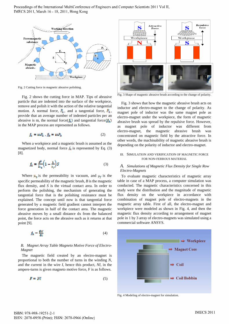
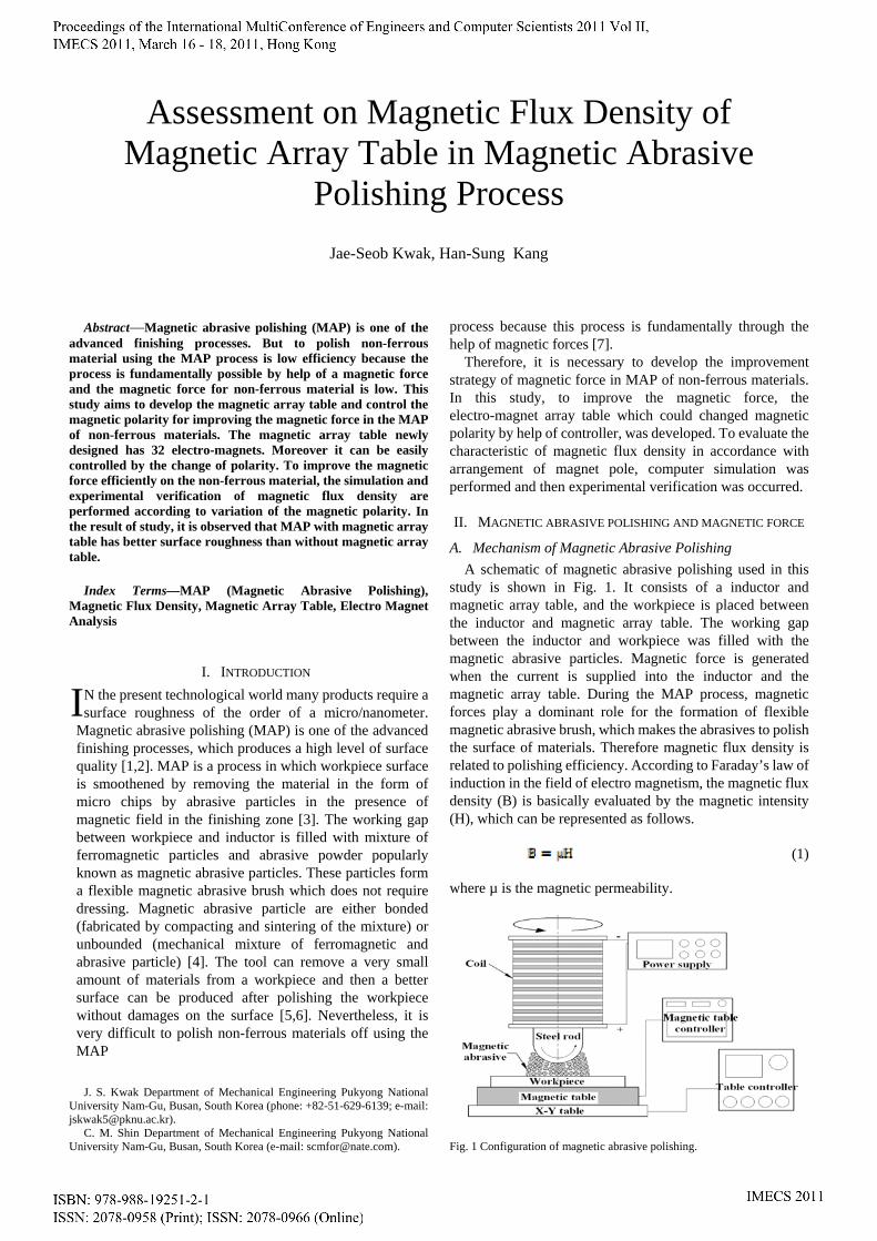
Fig. 2 Cutting force in magnetic abrasive polishing.
Fig. 2 shows the cutting force in MAP. Tips of abrasive particle that are indented into the surface of the workpiece, remove and polish it with the action of the relative tangential motion. A normal force, , and a tangential force, , provide that an average number of indented particles per an abrasive is m, the normal force( and tangential force in the MAP process are represented as follows. , (2)
When a workpiece and a magnetic brush is assumed as the magnetized body, normal force is represented by Eq. (3) [8].
(3)
Where is the permeability in vacuum, and is the
specific permeability of the magnetic brush, B is the magnetic flux density, and S is the virtual contact area. In order to perform the polishing, the mechanism of generating the tangential force that is the polishing resistance must be explained. The concept until now is that tangential force generated by a magnetic field gradient cannot interpret the force generation in half of the contact area. The magnetic abrasive moves by a small distance dx from the balanced point, the force acts on the abrasive such as it returns at that point [9].
(4)
B. Magnet Array Table Magneto Motive Force of Electro- Magnet
The magnetic field created by an electro-magnet is proportional to both the number of turns in the winding N, and the current in the wire I, hence this product, NI, in the ampere-turns is given magneto motive force, F is as follows. (5)
Fig. 3 Shape of magnetic abrasive brush according to the change of polarity.
Fig. 3 shows that how the magnetic abrasive brush acts on
inductor and electro-magnet to the change of polarity. As magnet pole of inductor was the same magnet pole as electro-magnet under the workpiece, the form of magnetic abrasive brush was spread by the repulsive force. However, as magnet pole of inductor was different from electro-magnet, the magnetic abrasive brush was concentrated on magnetic field by the attractive force. In other words, the machinability of magnetic abrasive brush is depending on the polarity of inductor and electro-magnet.
III. SIMULATION AND VERIFICATION OF MAGNETIC FORCE
FOR NON-FERROUS MATERIAL
A. Simulations of Magnetic Flux Density for Single Row Electro-Magnets To evaluate magnetic characteristics of magnetic array
table in case of a MAP process, a computer simulation was conducted. The magnetic characteristics concerned in this study were the distribution and the magnitude of magnetic flux density on the workpiece in accordance with combination of magnet pole of electro-magnets in the magnetic array table. First of all, the electro-magnet and workpiece were modeled as shown in Fig. 4, and then the magnetic flux density according to arrangement of magnet pole in 1 by 3 array of electro-magnets was simulated using a commercial software ANSYS.
Fig. 4 Modeling of electro-magnet for simulation.
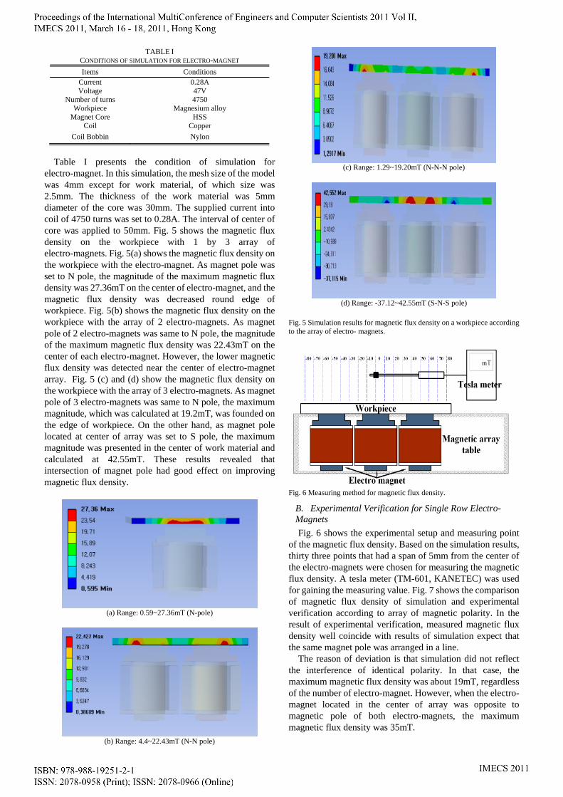
TABLE I CONDITIONS OF SIMULATION FOR ELECTRO-MAGNET
Items Conditions Current 0.28A Voltage 47V
Number of turns 4750 Workpiece Magnesium alloy
Magnet Core HSS Coil Copper
Coil Bobbin Nylon
Table I presents the condition of simulation for
electro-magnet. In this simulation, the mesh size of the model was 4mm except for work material, of which size was 2.5mm. The thickness of the work material was 5mm diameter of the core was 30mm. The supplied current into coil of 4750 turns was set to 0.28A. The interval of center of core was applied to 50mm. Fig. 5 shows the magnetic flux density on the workpiece with 1 by 3 array of electro-magnets. Fig. 5(a) shows the magnetic flux density on the workpiece with the electro-magnet. As magnet pole was set to N pole, the magnitude of the maximum magnetic flux density was 27.36mT on the center of electro-magnet, and the magnetic flux density was decreased round edge of workpiece. Fig. 5(b) shows the magnetic flux density on the workpiece with the array of 2 electro-magnets. As magnet pole of 2 electro-magnets was same to N pole, the magnitude of the maximum magnetic flux density was 22.43mT on the center of each electro-magnet. However, the lower magnetic flux density was detected near the center of electro-magnet array. Fig. 5 (c) and (d) show the magnetic flux density on the workpiece with the array of 3 electro-magnets. As magnet pole of 3 electro-magnets was same to N pole, the maximum magnitude, which was calculated at 19.2mT, was founded on the edge of workpiece. On the other hand, as magnet pole located at center of array was set to S pole, the maximum magnitude was presented in the center of work material and calculated at 42.55mT. These results revealed that intersection of magnet pole had good effect on improving magnetic flux density.
(a) Range: 0.59~27.36mT (N-pole)
(b) Range: 4.4~22.43mT (N-N pole)
(c) Range: 1.29~19.20mT (N-N-N pole)
(d) Range: -37.12~42.55mT (S-N-S pole)
Fig. 5 Simulation results for magnetic flux density on a workpiece according to the array of electro- magnets.
Fig. 6 Measuring method for magnetic flux density.
B. Experimental Verification for Single Row Electro- Magnets
Fig. 6 shows the experimental setup and measuring point of the magnetic flux density. Based on the simulation results, thirty three points that had a span of 5mm from the center of the electro-magnets were chosen for measuring the magnetic flux density. A tesla meter (TM-601, KANETEC) was used for gaining the measuring value. Fig. 7 shows the comparison of magnetic flux density of simulation and experimental verification according to array of magnetic polarity. In the result of experimental verification, measured magnetic flux density well coincide with results of simulation expect that the same magnet pole was arranged in a line.
The reason of deviation is that simulation did not reflect the interference of identical polarity. In that case, the maximum magnetic flux density was about 19mT, regardless of the number of electro-magnet. However, when the electro- magnet located in the center of array was opposite to magnetic pole of both electro-magnets, the maximum magnetic flux density was 35mT.
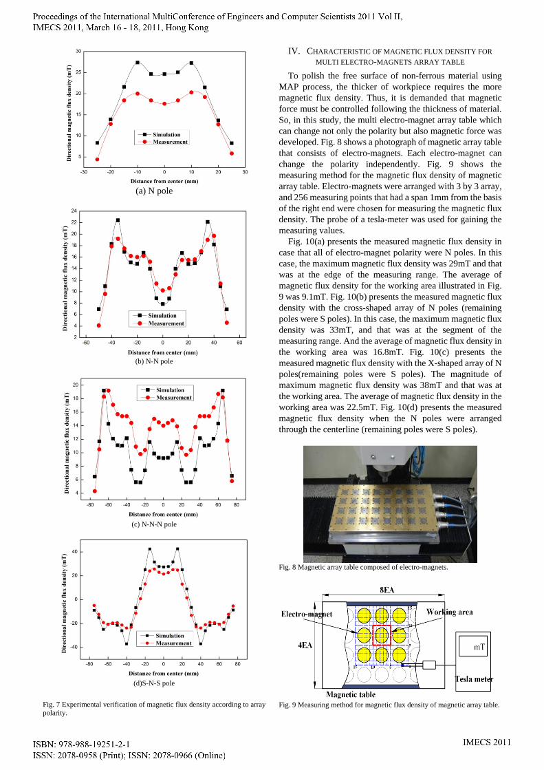
(a) N pole
(b) N-N pole
(c) N-N-N pole
(d)S-N-S pole
Fig. 7 Experimental verification of magnetic flux density according to array polarity.
IV. CHARACTERISTIC OF MAGNETIC FLUX DENSITY FOR
MULTI ELECTRO-MAGNETS ARRAY TABLE
To polish the free surface of non-ferrous material using MAP process, the thicker of workpiece requires the more magnetic flux density. Thus, it is demanded that magnetic force must be controlled following the thickness of material. So, in this study, the multi electro-magnet array table which can change not only the polarity but also magnetic force was developed. Fig. 8 shows a photograph of magnetic array table that consists of electro-magnets. Each electro-magnet can change the polarity independently. Fig. 9 shows the measuring method for the magnetic flux density of magnetic array table. Electro-magnets were arranged with 3 by 3 array, and 256 measuring points that had a span 1mm from the basis of the right end were chosen for measuring the magnetic flux density. The probe of a tesla-meter was used for gaining the measuring values.
Fig. 10(a) presents the measured magnetic flux density in case that all of electro-magnet polarity were N poles. In this case, the maximum magnetic flux density was 29mT and that was at the edge of the measuring range. The average of magnetic flux density for the working area illustrated in Fig. 9 was 9.1mT. Fig. 10(b) presents the measured magnetic flux density with the cross-shaped array of N poles (remaining poles were S poles). In this case, the maximum magnetic flux density was 33mT, and that was at the segment of the measuring range. And the average of magnetic flux density in the working area was 16.8mT. Fig. 10(c) presents the measured magnetic flux density with the X-shaped array of N poles(remaining poles were S poles). The magnitude of maximum magnetic flux density was 38mT and that was at the working area. The average of magnetic flux density in the working area was 22.5mT. Fig. 10(d) presents the measured magnetic flux density when the N poles were arranged through the centerline (remaining poles were S poles).
Fig. 8 Magnetic array table composed of electro-magnets.
Fig. 9 Measuring method for magnetic flux density of magnetic array table.
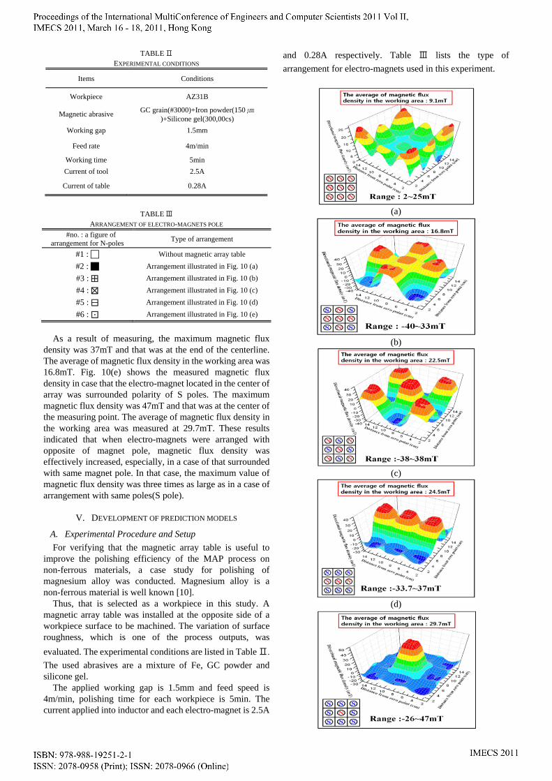
TABLE Ⅱ EXPERIMENTAL CONDITIONS
Items Conditions
Workpiece AZ31B
Magnetic abrasive GC grain(#3000)+Iron powder(150㎛
)+Silicone gel(300,00cs)
Working gap 1.5mm
Feed rate 4m/min
Working time 5min
Current of tool 2.5A
Current of table 0.28A
TABLE Ⅲ
ARRANGEMENT OF ELECTRO-MAGNETS POLE
#no. : a figure of arrangement for N-poles
Type of arrangement
#1 : Without magnetic array table
#2 : Arrangement illustrated in Fig. 10 (a)
#3 : ⊞ Arrangement illustrated in Fig. 10 (b)
#4 : ⊠ Arrangement illustrated in Fig. 10 (c)
#5 : ⊟ Arrangement illustrated in Fig. 10 (d)
#6 : ⊡ Arrangement illustrated in Fig. 10 (e)
As a result of measuring, the maximum magnetic flux
density was 37mT and that was at the end of the centerline. The average of magnetic flux density in the working area was 16.8mT. Fig. 10(e) shows the measured magnetic flux density in case that the electro-magnet located in the center of array was surrounded polarity of S poles. The maximum magnetic flux density was 47mT and that was at the center of the measuring point. The average of magnetic flux density in the working area was measured at 29.7mT. These results indicated that when electro-magnets were arranged with opposite of magnet pole, magnetic flux density was effectively increased, especially, in a case of that surrounded with same magnet pole. In that case, the maximum value of magnetic flux density was three times as large as in a case of arrangement with same poles(S pole).
V. DEVELOPMENT OF PREDICTION MODELS
A. Experimental Procedure and Setup
For verifying that the magnetic array table is useful to improve the polishing efficiency of the MAP process on non-ferrous materials, a case study for polishing of magnesium alloy was conducted. Magnesium alloy is a non-ferrous material is well known [10].
Thus, that is selected as a workpiece in this study. A magnetic array table was installed at the opposite side of a workpiece surface to be machined. The variation of surface roughness, which is one of the process outputs, was
evaluated. The experimental conditions are listed in Table Ⅱ. The used abrasives are a mixture of Fe, GC powder and silicone gel.
The applied working gap is 1.5mm and feed speed is 4m/min, polishing time for each workpiece is 5min. The current applied into inductor and each electro-magnet is 2.5A
and 0.28A respectively. Table Ⅲ lists the type of
arrangement for electro-magnets used in this experiment.
(a)
(b)
(c)
(d)
(e) Fig. 10 Magnetic flux density on electro-magnets array table, (a)#2:, (b)#3:⊞, (c)#4:⊠, (d)#5:⊟, (e)#6:⊡.
B. Experimental Results and Discussion
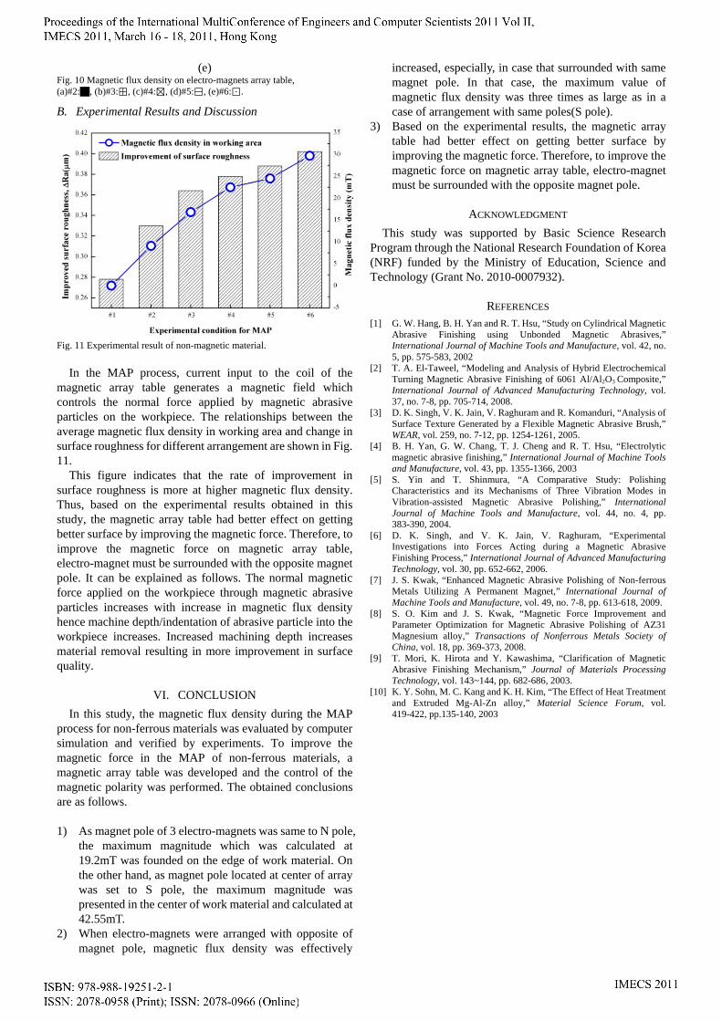
Fig. 11 Experimental result of non-magnetic material.
In the MAP process, current input to the coil of the
magnetic array table generates a magnetic field which controls the normal force applied by magnetic abrasive particles on the workpiece. The relationships between the average magnetic flux density in working area and change in surface roughness for different arrangement are shown in Fig. 11.
This figure indicates that the rate of improvement in surface roughness is more at higher magnetic flux density. Thus, based on the experimental results obtained in this study, the magnetic array table had better effect on getting better surface by improving the magnetic force. Therefore, to improve the magnetic force on magnetic array table, electro-magnet must be surrounded with the opposite magnet pole. It can be explained as follows. The normal magnetic force applied on the workpiece through magnetic abrasive particles increases with increase in magnetic flux density hence machine depth/indentation of abrasive particle into the workpiece increases. Increased machining depth increases material removal resulting in more improvement in surface quality.
VI. CONCLUSION
In this study, the magnetic flux density during the MAP process for non-ferrous materials was evaluated by computer simulation and verified by experiments. To improve the magnetic force in the MAP of non-ferrous materials, a magnetic array table was developed and the control of the magnetic polarity was performed. The obtained conclusions are as follows.
1) As magnet pole of 3 electro-magnets was same to N pole,
the maximum magnitude which was calculated at 19.2mT was founded on the edge of work material. On the other hand, as magnet pole located at center of array was set to S pole, the maximum magnitude was presented in the center of work material and calculated at 42.55mT.
2) When electro-magnets were arranged with opposite of magnet pole, magnetic flux density was effectively
increased, especially, in case that surrounded with same magnet pole. In that case, the maximum value of magnetic flux density was three times as large as in a case of arrangement with same poles(S pole).
3) Based on the experimental results, the magnetic array table had better effect on getting better surface by improving the magnetic force. Therefore, to improve the magnetic force on magnetic array table, electro-magnet must be surrounded with the opposite magnet pole.
ACKNOWLEDGMENT
This study was supported by Basic Science Research Program through the National Research Foundation of Korea (NRF) funded by the Ministry of Education, Science and Technology (Grant No. 2010-0007932).
REFERENCES [1] G. W. Hang, B. H. Yan and R. T. Hsu, “Study on Cylindrical Magnetic
Abrasive Finishing using Unbonded Magnetic Abrasives,” International Journal of Machine Tools and Manufacture, vol. 42, no. 5, pp. 575-583, 2002
[2] T. A. El-Taweel, “Modeling and Analysis of Hybrid Electrochemical Turning Magnetic Abrasive Finishing of 6061 Al/Al2O3 Composite,” International Journal of Advanced Manufacturing Technology, vol. 37, no. 7-8, pp. 705-714, 2008.
[3] D. K. Singh, V. K. Jain, V. Raghuram and R. Komanduri, “Analysis of Surface Texture Generated by a Flexible Magnetic Abrasive Brush,” WEAR, vol. 259, no. 7-12, pp. 1254-1261, 2005.
[4] B. H. Yan, G. W. Chang, T. J. Cheng and R. T. Hsu, “Electrolytic magnetic abrasive finishing,” International Journal of Machine Tools and Manufacture, vol. 43, pp. 1355-1366, 2003
[5] S. Yin and T. Shinmura, “A Comparative Study: Polishing Characteristics and its Mechanisms of Three Vibration Modes in Vibration-assisted Magnetic Abrasive Polishing,” International Journal of Machine Tools and Manufacture, vol. 44, no. 4, pp. 383-390, 2004.
[6] D. K. Singh, and V. K. Jain, V. Raghuram, “Experimental Investigations into Forces Acting during a Magnetic Abrasive Finishing Process,” International Journal of Advanced Manufacturing Technology, vol. 30, pp. 652-662, 2006.
[7] J. S. Kwak, “Enhanced Magnetic Abrasive Polishing of Non-ferrous Metals Utilizing A Permanent Magnet,” International Journal of Machine Tools and Manufacture, vol. 49, no. 7-8, pp. 613-618, 2009.
[8] S. O. Kim and J. S. Kwak, “Magnetic Force Improvement and Parameter Optimization for Magnetic Abrasive Polishing of AZ31 Magnesium alloy,” Transactions of Nonferrous Metals Society of China, vol. 18, pp. 369-373, 2008.
[9] T. Mori, K. Hirota and Y. Kawashima, “Clarification of Magnetic Abrasive Finishing Mechanism,” Journal of Materials Processing Technology, vol. 143~144, pp. 682-686, 2003.
[10] K. Y. Sohn, M. C. Kang and K. H. Kim, “The Effect of Heat Treatment and Extruded Mg-Al-Zn alloy,” Material Science Forum, vol. 419-422, pp.135-140, 2003