Embed Size (px)
Citation preview

EUROPEAN COMMISSIONDG-JRC – Institute for Advanced MaterialsJoint Research Centre
ASSESSMENT OF THE ISI SIMULATION PARTOF THE ENIQ PILOT STUDY
December 1999 ENIQ Report nr. 17 EUR 19025 EN
Approved by the Steering Committee of ENIQ
Directorate-GeneralJoint Research Centre
Published by theEUROPEAN COMMISSION
Directorate-GeneralTelecommunications, Information, Industries and Innovation
L-2920 LUXEMBOURG
LEGAL NOTICENeither the European Commission nor any person acting on behalf of the
Commission is responsible for the use which might be made of the followinginformation.
Catalogue number: CD-NA-19025-EN-C
ECSC-EEC-EAEC, Brussels – Luxembourg, 1999Printed in the Netherlands

ENIQ pilot study Assessment of the ISI simulation part of the ENIQ pilot study
1
CONTENTS
Contents .....................................................................................................................................1
1. Scope.....................................................................................................................................2
2. Applicable documents............................................................................................................2
3. Results obtained for the fatigue defects ................................................................................4
3.1 Components and defects.................................................................................................4
3.3 Conduct of the ISI simulation...........................................................................................6
3.4 Assessment of the obtained inspection results ...............................................................7
3.5 Conclusions .....................................................................................................................8
4. Results obtained for the “IGSCC” defects.............................................................................9
4.1 Test pieces and defects...................................................................................................9
4.2 Conduct of ISI simulation for the 1st set of test pieces containing “IGSCC” type defects
..............................................................................................................................................13
4.3 Assessment of the obtained inspection results .............................................................13
4.5 Conclusions ...................................................................................................................14
5. Comparison between qualification trials and ISI trials (1st set)..........................................15
6. Conclusions .........................................................................................................................18

ENIQ pilot study Assessment of the ISI simulation part of the ENIQ pilot study
2
1. SCOPE
The purpose of the first ENIQ pilot study was to verify he feasibility of the European
methodology and to explore ways of how to apply this methodology. During the pilot study
the European methodology was applied to a very specific inspection example. The main
steps of the pilot study consisted of qualifying the inspection of an austenitic pipe to pipe
weld through a combination of technical justification and practical trials and then applying the
qualified inspection to test pieces representing the actual component. The latter inspections
simulate the in service inspection. Comparison of the data obtained during qualification with
that from the “ISI” provides evidence for the effectiveness of the qualification. Therefore it is
important that the results obtained in the blind and open qualification trials on the one hand
and in the ISI trials on the other hand, were consistent with each other, independently of
whether the inspection results themselves were good or bad.
Two sets of ISI assemblies were inspected: a first set which is very similar to the qualification
test pieces and second set which is not.
In this report the results are reported on the first set of ISI assemblies, which is, as
mentioned before, very similar to the qualification test pieces (materials used, structure and
defects inserted). The 2nd set of ISI specimens was removed from American Boiling Water
Reactors (BWR). However, as a result of the pilot study, it has now been appreciated that
the defects in these specimens offer a valuable and unique opportunity to collect data about
real IGSCC and its ultrasonic response. Consequently, it has been decided to carry out
extensive further measurements on these samples before they are sectioned. As a result,
there is no precise knowledge of the nature or size of the defects in these particular test
pieces. The results on this second set will be reported later once the destructive examination
results are known.
2. APPLICABLE DOCUMENTS
The following documents were used during the assessment:
Ø European methodology for qualification of NDT, EUR EN 17299, Published by the
European Commission, Brussels-Luxembourg, 1997
Ø QA programme (first ENIQ pilot study), ENIQ Report 8, EUR 18112 EN, Published by
the European Commission, Brussels-Luxembourg, 1998
Ø Input information (first ENIQ pilot study), ENIQ Report 7, EUR 18111 EN, Published
by the European Commission, Brussels-Luxembourg, 1998

ENIQ pilot study Assessment of the ISI simulation part of the ENIQ pilot study
3
Ø Qualification procedure (first ENIQ pilot study), ENIQ Report 9, EUR 18113 EN,
Published by the European Commission, Brussels-Luxembourg, 1998
Ø ENIQ.PILOT(96)8: Detailed description of the qualification test pieces
v Part I: test pieces used for the open trials (draft of 25 April 1997)
v Part II: test pieces used for the blind trials (under preparation)
Ø Results of the destructive examination of the ENIQ pilot study: defect catalogue, ENIQ
Report 19, EUR 19024 EN, Published by the European Commission, Brussels-
Luxembourg, 1999
Ø Assessment of the results of the qualification part of the pilot study (post-destructive
examination), ENIQ Report 16, EUR 19023 EN, Published by the European
Commission, Brussels-Luxembourg, 1999
It is important to mention also the final report on the pilot study in which all the results
achieved during the ENIQ pilot study are summarised (ENIQ Report 20, EUR 19026 EN).

ENIQ pilot study Assessment of the ISI simulation part of the ENIQ pilot study
4
3. RESULTS OBTAINED FOR THE FATIGUE DEFECTS
3.1 COMPONENTS AND DEFECTS
Two components, ENIQ test piece 11 and 13, were used for the simulation of the ISI
inspection.
In Table 1 an overview is given of the essential parameters identified for the components
and to which extent the ISI components are within the tolerance/range given for the different
essential parameters.
ENIQ test piece 11 contained 1 real fatigue crack. ENIQ test piece 13 did not contain any
defects at all. Information on the dimension of the real fatigue crack can be found in Table 2.

ENIQ pilot study Assessment of the ISI simulation part of the ENIQ pilot study
5
Table 1: Overview of extent to which the first set of ISI specimens are within the
range/tolerance of the identified essential parameters (case of fatigue cracks) Essential parameters
component
Range Extent to which test pieces are within
variation of essential parameters
Geometry of
component
No, double sided access All straight tubes
Weld crown
configuration
Less than 1.5 mm over a
surface of 50 mm x 50 mm
Test pieces within these limits
Weld root Length: 0-30 mm
Protruding part: maximum 4
mm
• ENIQ 11: ground, presence of
buttering used to introduced fatigue
crack
• ENIQ 13: not ground (within limits as
given)
Wall thickness 13.5 - 30 mm Wall thickness considered:
ENIQ 11:28 mm
ENIQ 13: 28 mm
Pipe diameter 320- 700 mm Diameters considered:
• 407 mm (2 x)
Counterbore taper
angle
< 30 ° • ENIQ 11: taper angle in some
location larger than 30°
• ENIQ 13: within tolerance given
Position counterbore
with respect to weld
center line
Between 5 and 180 mm • Case of 180 mm considered in 2
assemblies
• Counterbore geometry in ENIQ 11
very irregular as compared to other
test pieces
Macrostructure base
material
Similar base material as
qualification test pieces
Macrostructure weld
material
Similar welding procedure
as qualification test pieces
Table 2: Dimensions of fatigue crack (normal weld) present in test piece 11 used for the ISI
simulation (1st set of ISI specimens) Defect
number
Type of
defect
Defect
position in
weld
Through-wall extent
(mm)
through-wall extent
(% of wall thickness)
Length
(mm)
11.1 Fatigue
crack
Weld 13 48 73
ENIQ pilot study Assessment of the ISI simulation part of the ENIQ pilot study
6
The fatigue crack had a tilt and skew angle of 0º. Destructive examination learned that the
defect consisted of 2 parallel parts of which one is longer than the other. Furthermore, there
was also still the presence of a buttering layer of about 1 mm. This buttering layer is the
remnant part of a buttering in which a starter notch for the fatigue crack has been introduced.
This buttering was not completely removed after introduction of the fatigue crack and is
clearly visible on the ultrasonic images.
It should be mentioned that the manufacturer had quite some problems with the introduction
of the fatigue cracks in this test piece. Originally the Reference Laboratory had asked for 2
fatigue defects in ENIQ test piece 11. However the presence of the second fatigue crack
could not be confirmed by destructive examination. Also the inspection teams did not report
any indication corresponding with this second fatigue crack.
As already mentioned the characteristics of the counterbore area of ENIQ 11 are very
different from what was done for all the other test pieces by the same manufacturer. This is
probably due to the fact that additional machining was performed in order to remove the
buttering used for the starter notch of the fatigue crack.
3.3 CONDUCT OF THE ISI SIMULATION
The inspection for the 1st set of ISI specimens was conducted in 2 times. ENIQ 10, 12 and
13 were inspected in the period of from 24/3/97 till 27/3/97 and from 7/4/97 till 10/4/97.
ENIQ 11 (due to the late delivery time) was inspected from 21/1/98 till 29/1/98. The
inspection was performed by the following persons:
• Team leader and overview of inspection activities (data acquisition and data
interpretation): B. Eriksen (level III ultrasonics), JRC Petten
• Data acquisition and data interpretation: G.-P. Battagin, JRC Petten
The ISI simulation was continuously invigilated by H. Lohner (JRC Petten). A log book was
kept in which all activities are noted. Here follows an overview of the sequence of events
during the ISI smulation (1st set):
• 24/3-25/3: ENIQ 10, detection and sizing
• 25/3-27/3: ENIQ 12, detection and sizing
• 7/4-10/4/97: ENIQ 13, detection and sizing
• 21/1/-29/1/98: ENIQ 11, detection and sizing
ENIQ pilot study Assessment of the ISI simulation part of the ENIQ pilot study
7
3.4 ASSESSMENT OF THE OBTAINED INSPECTION RESULTS
Detection
The fatigue crack was correctly detected. The inspection team also correctly characterised
the defect by stating that it was multi-branched.
False calls
No false calls were made by the inspection team in ENIQ test piece 13, that did not contain
any defects.
However the inspection team reported 2 relatively long indications in ENIQ test piece 11 with
a through-wall extent of 4 and 9.5 mm, respectively. The specific geometry of the
counterbore of ENIQ test piece 11 is very different from those present in the other test
pieces. Its shape is very irregular and the surface is rough, which is probably the cause of
reflections which were misinterpreted by the inspection team as defects. This is very clear
when comparing the ultrasonic signals coming from the counterbore of ENIQ 11 with those
observed on other test pieces.
The fact that false calls were made on this assembly during the ISI simulation can be
attributed to the fact that the counterbore of ENIQ 11 is completely different from those of the
qualification test piece. The problem revealed here is hence not one of the European
methodology but rather one of correct input information. Two questions arise here:
• Does the the counterbore geometry of ENIQ 11 falls within the range/tolerance of
counterbore essential input parameters which have been defined?
• Have the correct essential input parameters for the counterbore been considered in the
input information?
Irregular shape or rough counterbore surface seem to be parameters which affect more
significantly the inspection performance than the taper angle. It is clear that the geometry of
the counterbore of ENIQ 11 was not considered in the qualification trials.
Depth sizing
The inspection team reported a through-wall extent of 13.8 mm which can be considered as
a satisfactory result when compared with the through-wall extent of 13 mm measured by
destructive examination.
ENIQ pilot study Assessment of the ISI simulation part of the ENIQ pilot study
8
Length sizing
The inspection team gave for the fatigue crack a length of 125 as compared to the 73 mm
measured by destructive examination. The error made of 52 mm is relatively large. Further
investigation after the ISI trials of the ultrasonic signal used to measure the crack length
learned that the defect signal can be subdivided in 2 parts. There is a very clear indication,
the length of which as measured by ultrasonics is 82 mm.
However, next to this indication, along the weld center line, there are a number of
intermittent smaller indications which the inspection team grouped together with the large
“defect” signal as one indication. The origin of these smaller indications is not completely
clear but has most probably to do with the defect manufacturing method used. They can
certainly not come from the weld root as it was removed when the buttering layer was
machined away.
3.5 CONCLUSIONS
Although the detection and depth sizing criteria were met during the ISI simulation for the
fatigue type defects that was not the case for length sizing and false calls:
• two false calls were made in the counterbore area of one of the ISI test pieces (ENIQ
11)
• the length of the fatigue crack was oversized significantly
The fact that 2 false calls were made in ENIQ 11 can be attributed to the fact that the
specific geometry of the counterbore of this test piece is completely different from that of the
other test pieces.
The problem revealed here is hence not one of the European methodology but rather one of
incorrect input information.
The inspection team gave for the fatigue crack a length of 125 as compared to the 73 mm
measured by destructive examination. The error made of 62 mm is relatively large. The
origin of a number of smaller indications next to the main indication corresponding with the
fatigue crack is not completely clear but has most probably to do with the defect
manufacturing method used..
Note that the obtained inspection results for the fatigue type defect during the ISI trials are
conservative and are not safety significant. The discrepancies observed between the
ENIQ pilot study Assessment of the ISI simulation part of the ENIQ pilot study
9
qualification and ISI trials can be attributed on the one hand to an incorrect definition of the
input information for what concerns the counterbore and on the other hand to (probably) the
defect manufacturing method used to introduce realistic fatigue cracks. They are not due to
application of the European methodology in one way or the other.
4. RESULTS OBTAINED FOR THE “IGSCC” DEFECTS
4.1 TEST PIECES AND DEFECTS
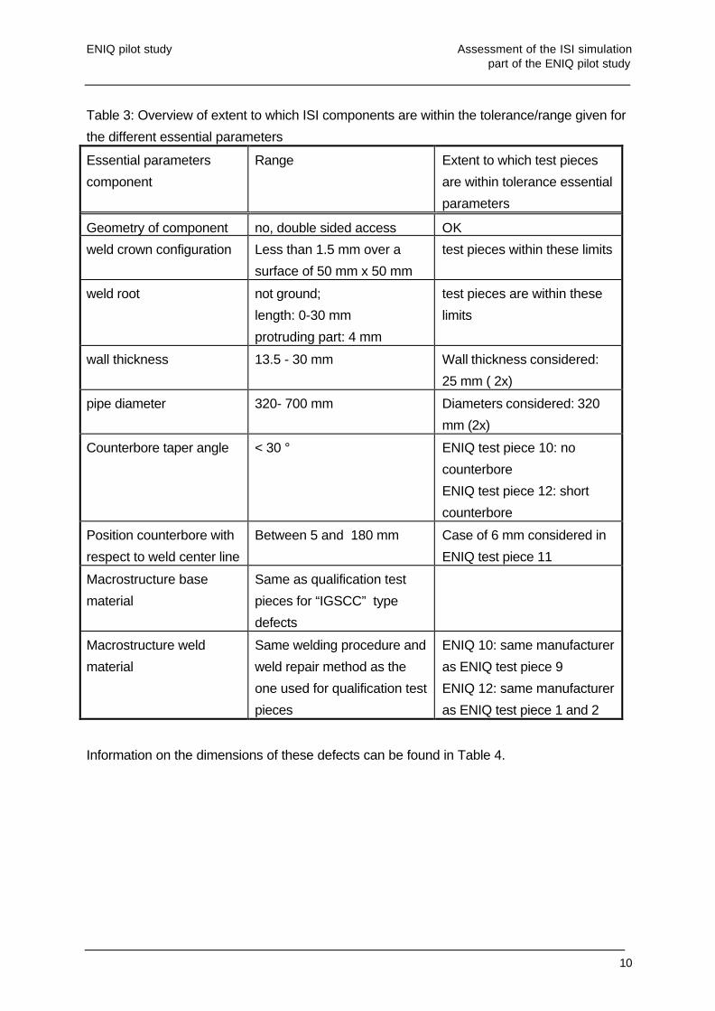
In total 7 defects, simulating “IGSCC” type defects, and introduced in 2 different assemblies
(ENIQ 10, ENIQ 12) were used for the 1st set of ISI specimens.
In Table 3 an overview is given of the essential parameters identified for the components
and to which extent the ISI components are within the tolerance/range given for the different
essential parameters.
ENIQ pilot study Assessment of the ISI simulation part of the ENIQ pilot study
10
Table 3: Overview of extent to which ISI components are within the tolerance/range given for
the different essential parameters
Essential parameters
component
Range Extent to which test pieces
are within tolerance essential
parameters
Geometry of component no, double sided access OK
weld crown configuration Less than 1.5 mm over a
surface of 50 mm x 50 mm
test pieces within these limits
weld root not ground;
length: 0-30 mm
protruding part: 4 mm
test pieces are within these
limits
wall thickness 13.5 - 30 mm Wall thickness considered:
25 mm ( 2x)
pipe diameter 320- 700 mm Diameters considered: 320
mm (2x)
Counterbore taper angle < 30 ° ENIQ test piece 10: no
counterbore
ENIQ test piece 12: short
counterbore
Position counterbore with
respect to weld center line
Between 5 and 180 mm Case of 6 mm considered in
ENIQ test piece 11
Macrostructure base
material
Same as qualification test
pieces for “IGSCC” type
defects
Macrostructure weld
material
Same welding procedure and
weld repair method as the
one used for qualification test
pieces
ENIQ 10: same manufacturer
as ENIQ test piece 9
ENIQ 12: same manufacturer
as ENIQ test piece 1 and 2
Information on the dimensions of these defects can be found in Table 4.

ENIQ pilot study Assessment of the ISI simulation part of the ENIQ pilot study
11
Table 4: Defects used to simulate “IGSCC” type defects, present in the test pieces used for
the 1st set of ISI specimens
Defect
number
defect type Position through-wall extent
(% of wall
thickness)
Through-wall
extent (mm)
length (mm)
10.1 “IGSCC” Weld 91 22.9 62
10.2 “IGSCC” Weld 21 5.3 51
10.3 “IGSCC” Weld 46 11.6 42
10.4 “IGSCC” Weld 77 19.6 52
12.1 “IGSCC” Weld 24 6 23
12.2 “IGSCC” Weld 50 12.2 30
12.3 “IGSCC” Weld 66 15.9 49
Note that ENIQ 9 (blind trials) and 10 were fabricated by the same manufacturer and that
ENIQ 12 was fabricated by the same manufacturer as ENIQ 1 and 2. The results of
destructive examination of these defects can be found in the defect catalogue (see section
2) but they are very similar to what was found for the qualification test pieces.
In Table 5 an overview is given of the essential parameters identified for the defects and to
which extent the defects in the ISI components are within the tolerance/range given for the
different essential parameters.

ENIQ pilot study Assessment of the ISI simulation part of the ENIQ pilot study
12
Table 5: Overview of extent to which variation of essential defect parameters was covered
with the “IGSCC” type defects introduced in the 1st set of ISI specimens
Essential parameters
defects
Range extent to which test pieces
are within tolerance defined
for the essential parameters
defect size 3 mm - 100 % TWE OK
defect position along
TWE
not relevant for “IGSCC” as
they are all surface-
breaking
-
defect position with
respect to weld center
line
weld OK
tilt angle 0-30 ° worst case is 0°
all defects are at 0°
skew angle ±10 ° all defect are at 0°
Roughness of “IGSCC”
type defects
Similar as in qualification
test pieces
Branching of “IGSCC”
type defects
Similar as in qualification
test pieces
In Table 6 the different limit cases are given for the defects, which were identified as a result
of the technical justification.
Table 6: Different limit cases for the “IGSCC” type defects, considered in the 1st set of ISI
specimens
different limit cases for
“IGSCC”
Requirement Situation for 1st set
of ISI specimens
detection “IGSCC” : small
size
At least 2 defects with size <
a100
Size < a100: 2
a100 < size < aqual : 1
size > aqual: 4
detection “IGSCC” :
• Tilt of 0°
• Skew ± 10°
At least 2 defects of each
case
tilt: 4 at 0°
skew: all 0°
sizing “IGSCC” : small and
large size
At least 2 defects with size <
a100
At least 2 defects with size >
aqual
Size < a100: 2
a100 < size < aqual : 1
size > aqual: 4

ENIQ pilot study Assessment of the ISI simulation part of the ENIQ pilot study
13
4.2 CONDUCT OF ISI SIMULATION FOR THE 1ST SET OF TEST PIECES CONTAINING
“IGSCC” TYPE DEFECTS
The inspection of the components (ENIQ 10 and 12) containing “IGSCC” type defects was
conducted in conjunction with that of ENIQ 11 and 13 (see section 3.2).
4.3 ASSESSMENT OF THE OBTAINED INSPECTION RESULTS
Detection
All defects were detected.
False calls
No false calls were made in either ENIQ test piece 10 or 12.
Depth sizing
In Table 7 a summary is given for the depth sizing performance achieved for the “IGSCC”
type defects.
Table 7: Depth sizing performance for the “IGSCC” type defects, achieved during the ISI
simulation trials (1st set)
Defect
Number
Reference
TWE
Measured
TWE (mm)
Sizing error
(mm)
Remarks
10.1 22.9 19.9 - 3.0 Probably signal from defect
10.2 5.3 13 + 7.7 Signal from implant
10.3 11.6 14.8 + 3.2 Signal from implant
10.4 19.6 17.9 - 1.7 Probably signal from defect
12.1 6.0 7.9 +1.9 Probably signal from defect
12.2 12.2 16.6 +4.2 ?
12.3 15.9 16.1 0.2 Probably signal from defect
The oversizing results made for defects 10.2 and 10.3 can be attributed to the implant. The
large sizing error made for defect 12.2 can not be readily explained.

ENIQ pilot study Assessment of the ISI simulation part of the ENIQ pilot study
14
None of the defects was undersized by more than 25 % of the wall thickness.
The RMS error considering all defects is 3.8 mm. The RMS error is 4.5 mm considering only
the defects of ENIQ test piece 10 and is 2.4 mm considering only the defects of test piece
12.
Length sizing
The length sizing results obtained for the 1st set of ISI specimens containing “IGSCC” type
defects are summarised in Table 8. The corresponding RMS error is 15.6 mm. Considering
only test piece 10 the RMS error is 14.0 mm. Considering only test piece 12 the RMS error
is 17.5 mm.
Table 8: Length sizing performance for “IGSCC” achieved during ISI simulation (1st set of ISI
specimens)
Defect Reference length
(mm)
Measured
length (mm)
Sizing error made (mm)
10.1 62 66 + 4
10.2 51 49 - 2
10.3 42 68 + 26
10.4 52 42 -10
12.1 23 36 + 13
12.2 30 41 + 11
12.3 49 74 + 25
4.5 CONCLUSIONS
For what concerns the IGSCC type defects all ISI objectives were met during the
qualification and ISI trials except for depth sizing.
For depth sizing no undersizing errors were made larger than 25 % of the wall thickness.
The RMS error criterion was, however, in general not met.
The fact that the RMS error criterion was not met can most probably be attributed to the
defect manufacturing method used for the IGSCC type defects.

ENIQ pilot study Assessment of the ISI simulation part of the ENIQ pilot study
15
5. COMPARISON BETWEEN QUALIFICATION TRIALS AND ISI TRIALS (1ST SET)
An overview of the extent to which the ISI objectives were met during qualification and ISI
simulation is given in Table 9 for what concerns the fatigue defects and in Table 10 for what
concerns the “IGSCC” type defects.

ENIQ pilot study Assessment of the ISI simulation part of the ENIQ pilot study
16
Table 9: Overview of the extent to which the ISI objectives were met during qualification and ISI simulation for the fatigue defects Requirement Technical justification Open trials Blind trials ISI
100 % detection rate or
defects exceeding 25 %
TWE
Evidence given:
• PISC III trials
• Limited laboratory trials
OK (12 out of 12) OK (11 out of
11)
OK 1 out of 1
80 % detection rate for
defects between 3 mm
and 25 % TWE
Evidence given:
• PISC III trials
• Limited laboratory trials
OK (1 out of 1) OK (1 out of 1) No such defects present
Maximum undersizing
permitted is 25 % TWE
or 5 mm
Limited evidence on depth sizing given OK OK OK
RMS error for depth
sizing < 3 mm
Limited evidence on depth sizing given OK
RMS = 1.9 mm
OK
RMS = 1.6 mm
Absolute depth sizing error
= 0.8 mm
RMS error for length
sizing < 20 mm
No evidence given as amplitude drop
methods are commonly used methods for
length sizing
OK
RMS = 7.4 mm
OK
RMS = 6.0 mm
Absolute length sizing error
is 62 mm
false calls • Not treated explicitly in technical
justification
• A lot of effort was devoted to optimising
decision tree for detection/sizing
OK OK - 2 false calls in
counterbore of ENIQ 11
- geometry of
counterbore of ENIQ 11
not considered during
qualification

ENIQ pilot study Assessment of the ISI simulation part of the ENIQ pilot study
17
Table 10: Overview of the extent to which the ISI objectives were met during qualification and ISI simulation for the “IGSCC” type defects Requirement Technical justification Open trials Blind trials ISI
all ENIQ 10
(similar to test
piece used for
blind trials)
ENIQ 12
(similar to test
piece for open
trials)
100 % detection rate for defects
exceeding 25 % TWE
Evidence given:
• PISC III trials
• Limited laboratory trials
OK, 3 out of 3 OK, 3 out of 3 OK (5 out of 7) OK (3 out of 3) OK (2 out of 2)
80 % detection rate for defects
between 3 mm and 25 % TWE
Evidence given:
• PISC III trials
• Limited laboratory trials
OK, 1 out of 1 OK, 1 out of 1 OK (2 out of 2) OK (1 our of 1) OK (1 out of 1)
Maximum undersizing permitted
is 25 % TWE or 5 mm
Limited evidence on depth sizing
given
OK OK
OK OK OK
RMS error for depth sizing < 3
mm
Limited evidence on depth sizing
given
Not met
RMS = 4.4 mm
Not met
RMS = 4.6 mm
(implant)
RMS = 1.8 mm
(defects)
Not met
RMS = 3.8 mm
Not met
RMS error =
4.5 mm
(implant)
Met
RMS error =
2.4 mm
RMS error for length sizing < 20
mm
No evidence given as amplitude
drop methods are commonly used
methods for length sizing
OK
RMS = 19.6
mm
OK
RMS = 11.6
mm
OK
RMS error = 15.6
mm
OK
RMS error =
14.0 mm
OK
RMS error =
17.5 mm
false calls • Not treated explicitly in
technical justification
• A lot of effort was devoted to
optimising decision tree for
detection/sizing
OK OK OK
No false calls
OK
No false calls
OK
No false calls
ENIQ pilot study Assessment of the ISI simulation part of the ENIQ pilot study
18
6. CONCLUSIONS
One of the major objectives of the pilot study was to verify the feasibility of the inspection
qualification principles as given in the European methodology.
During the pilot study the European methodology was applied to a very specific inspection
example. The main steps of the pilot study consisted of qualifying the inspection of an
austenitic pipe to pipe weld through a combination of technical justification and practical
trials and then applying the qualified inspection to test pieces representing the actual
component. The latter inspections simulate the in service inspection. Comparison of the data
obtained during qualification with that from the “ISI” provides evidence for the effectiveness
of the qualification.
In this report the results are reported on a first set of ISI assemblies, which is very similar to
the qualification test pieces (materials used, structure and defects inserted)
A 2nd set of ISI specimens that were removed from American was also inspected. However
as a result of the pilot study, it has now been appreciated that the defects in these
specimens offer a valuable and unique opportunity to collect data about real IGSCC and its
ultrasonic response. Consequently it has been decided to carry out extensive further
measurements on these samples before they are sectioned. As a result, there is no precise
knowledge of the nature or size of the defects in these particular test pieces.
The purpose of the ENIQ pilot study was to verify the feasibility of the European
methodology. Therefore it was important that the results obtained in the blind and open
qualification trials on the one hand and in the ISI trials, obtained on a set of ISI specimens
made using the same welding methods as the qualification test pieces, on the other hand,
were consistent with each other, independently of whether they were good or bad.
In most cases it was demonstrated that the inspection personnel, procedure and equipment
met the inspection and qualification objectives set. This was confirmed by the results
obtained in the inspection of the 1st set of ISI specimens.
In case of depth sizing of the IGSCC type defects it was not possible to meet the RMS
criteria. This was the case during the open and blind trials and was confirmed during the ISI
trials. The problems observed for depth sizing of the IGSCC type defects can be attributed to
the defect manufacturing methods used
ENIQ pilot study Assessment of the ISI simulation part of the ENIQ pilot study
19
There were 2 cases where the results between the qualification trials and the ISI trials were
not consistent.
The first case concerns different inspection results due to the geometry of the counterbore
which was completely different in one of the ISI test pieces as compared to that found in all
other test pieces (both ISI and qualification). This difference observed between the
qualification and ISI trials can therefore be attributed to an incorrect definition of the input
information. This shows the need to identify all essential parameters for a particular
inspection and to ensure that test piece design takes account of these.
The second case where a difference has been observed between qualification and ISI trials
concerns the length sizing problems observed for the fatigue defect, which could be
attributed to the defect manufacturing method.
Finally, it can be concluded that the results obtained in the framework of this pilot study show
that the European methodology is a satisfactory basis for qualification. The consistent results
obtained during qualification and ISI trials demonstrate this. The problems which were
observed were not due to inherent weaknesses of the European methodology but could be
attributed to differences in test piece features of significance to NDT from those of the real
components to be inspected (incorrectly defined input information) and the specific defect
manufacturing methods used. These problems would have arisen also with other
qualification methods.
The major conclusion one can draw for these ISI trials is that the inspection results are
consistent with the results achieved during the qualification trials which provides evidence for
the effectiveness of the qualification approach followed.

EUROPEAN COMMISSION
EUR 19025 EN 19 pages
Editors: P. Lemaitre, B. Eriksen, M. Melbi
Luxembourg: Office for Official Publications of the European Communities
1999 – 19 pag. – 21.0 x 29.7 cm
Physical sciences
EN
Catalogue number: CD-NA-19025-EN-C
Copies of this ENIQ report can be obtained by writing to the following address:JRC PettenInstitute for Advanced MaterialsP.O. Box 2NL – 1755 ZG PettenThe Netherlands
ABSTRACT
The present report gives the results of the ISI simulation part of the first ENIQ pilot study.The pilot study has also revealed features of qualification that require further work and thereport discusses this. In addition, the pilot study showed the need for a number ofRecommended Practices on different aspects of qualification according to the ENIQMethodology to clarify how it should be carried out. It also provided information on how theseshould be written.

The Joint Research Centre
The mission of the Joint Research Centre is to provide customer-driven scientific andtechnical support for the conception, development, implementation and monitoring ofEuropean Union policies.
As a service of the European Commission, the JRC functions as a centre of science andtechnology reference for the Union. Close to the policy-making process, it serves thecommon interest of the Member States, while being independent of special interests,private or national.
The JRC carries out Community research programmes decided by the Council and funded bythe European Union budget with additional funding from associated countries. It alsoprovides customer-driven research as scientific and technical support for other Communitypolicies, such as those on the environment, agriculture or nuclear safety. It is involved incompetitive activities in order to validate its expertise and increase its know-how in its corecompetencies. Its guiding line is that of “adding value” where appropriate rather thancompeting directly with establishments in the Member States.
Five separate sites, located in Belgium, Germany, Italy, The Netherlands and Spain, housethe eight JRC institutes, each with its own focus of expertise.
The institutes produce their own Annual Reports, where readers will find more detailedinformation. The JRC also publishes numerous technical reports and contributes to scientificjournals, presents papers to conferences and organises workshops to disseminate itsscientific output. Further information can be found on the JRC website: www.jrc.org.