Embed Size (px)
Citation preview
Western Kentucky UniversityTopSCHOLAR®
Masters Theses & Specialist Projects Graduate School
Fall 12-2012
Assessment of Passive Fire Protection on Steel-Girder BridgesMichael Davidson
Follow this and additional works at: http://digitalcommons.wku.edu/theses
Part of the Civil Engineering Commons, and the Physics Commons
This Thesis is brought to you for free and open access by TopSCHOLAR®. It has been accepted for inclusion in Masters Theses & Specialist Projects byan authorized administrator of TopSCHOLAR®. For more information, please contact [email protected].
Recommended CitationDavidson, Michael, "Assessment of Passive Fire Protection on Steel-Girder Bridges" (2012). Masters Theses & Specialist Projects. Paper1213.http://digitalcommons.wku.edu/theses/1213

ASSESSMENT OF PASSIVE FIRE PROTECTION ON STEEL-GIRDER BRIDGES
A Thesis Presented to
The Faculty of the Department of Physics & Astronomy Western Kentucky University
Bowling Green, Kentucky
In Partial Fulfillment Of the Requirements for the Degree
Master of Science in Homeland Security Sciences
By Michael Davidson
December 2012
iii
ACKNOWLEDGEMENTS
The author wishes to thank the Western Kentucky University Department of
Physics & Astronomy and the Department of Homeland Security (DHS) for providing the
funding that made this study possible. The author is grateful to Dr. Issam Harik of the
University of Kentucky Civil Engineering Department for his mentoring, and for
initiating the author’s involvement in research on infrastructure fire-safety. Royce
Meredith is additionally thanked for providing structural drawings and photographs of the
bridge that was considered in this study. The author also wishes to thank the faculty
members who served on the graduate committee. Namely, Dr. Alexander Barzilov and
Dr. Ivan Novikov are thanked for their guidance and insight in identifying research
objectives that may benefit the DHS. Further, the author wishes to thank Dr. Keith
Andrew for using his overarching perspective in shaping the research directions and
outcomes. Finally, the author wishes to thank Dr. Shane M. Palmquist for providing his
valuable input regarding the structural engineering aspects of the work.
iv
TABLE OF CONTENTS
LIST OF FIGURES ......................................................................................................... viii
LIST OF TABLES ........................................................................................................... xiv
ABSTRACT .......................................................................................................................xv
INTRODUCTION ...............................................................................................................1
Fire-Safety Experiments and Analytical Studies for Bridges ........................................3
Analytical Studies ....................................................................................................4
Ongoing Studies .......................................................................................................5
Scope of Research ..........................................................................................................6
BEHAVIOR OF STRUCTURAL AND FIRE-PROTECTION MATERIALS WHEN
SUBJECTED TO ELEVATED TEMEPRATURES .....................................................8
Structural Steel and Concrete at the Material Level ......................................................9
Spalling Effects of Concrete ..................................................................................10
Illustration of Temperature Effects on Structural Members from Transportation
Structures using Finite Element Analysis (FEA) ...................................................11
Overview of Loading Considered ..........................................................................12
Structural Steel Member ........................................................................................12
Reinforced Concrete (R/C) Member ......................................................................16
Fire Protection Materials..............................................................................................21
v
Protective Cladding ................................................................................................22
Refractory Cement .................................................................................................24
Intumescent Coatings .............................................................................................26
NEEDS AREAS AND IMPACT OF FIRE ON STEEL-GIRDER BRIDGES .................28
Fire Incidents ...............................................................................................................28
Nine Mile Road Fire (2009) ...................................................................................29
Explosive Effects ...................................................................................................31
Fire Protection Standards .............................................................................................32
Design-Fires for Bridges ..............................................................................................32
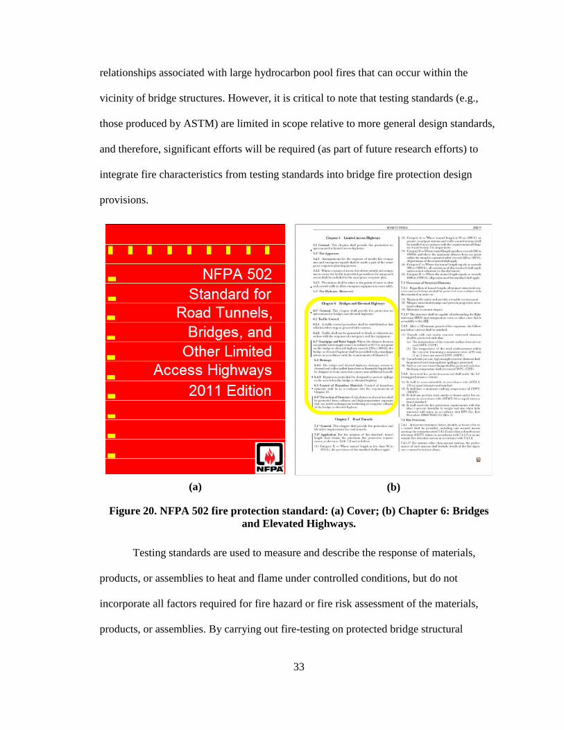
ASTM E1529 ...............................................................................................................34
Fire Conditions.......................................................................................................36
Comparison of ASTM E1529 Fire Conditions to Forensic Findings ....................37
Maximum Permitted Temperatures of Substrate Materials ...................................39
Candidate Passive Fire Protection Materials ...............................................................39
Intumescent Coatings .............................................................................................40
Refractory Cements ...............................................................................................41
STEEL-GIRDER BRIDGE SELECTED FOR USE IN SEVERE-FIRE ASSESSMENTS
OF PASSIVE FIRE PROTECTON MATERIALS .....................................................42
Introduction ..................................................................................................................42
vi
Motivation for Selection ........................................................................................44
Structural Configuration ..............................................................................................44
Steel-girder Superstructure ....................................................................................45
Superstructure Bearings .........................................................................................47
Pier Cap and Columns ...........................................................................................49
Pier Footings and Soil ............................................................................................50
Abutments ..............................................................................................................50
Geometric Modeling Considerations ...........................................................................51
Finite Element (FE) Bridge Model Discretization .................................................52
Substructure-Superstructure Modeling Above the Central Pier ............................54
Essential Mechanical Boundary Conditions ..........................................................56
Element Discretization of Fire Protection Materials .............................................58
CONSTITUTIVE AND THERMAL MODELING ..........................................................61
Constitutive Modeling .................................................................................................61
Reinforced Concrete Material Models for Shell Elements ....................................61
Reinforced Concrete Material Model for Solid Elements .....................................64
A36 Structural Steel ...............................................................................................65
Refractory Cement .................................................................................................70
Intumescent Coating ..............................................................................................73
vii
Determination of Severe-Fire Scenario .......................................................................74
Lime Kiln Lane Overpass Fire (2011) ...................................................................75
Source and Distribution of Fire ..............................................................................77
ANALYTICAL ASSESSMENT OF PASSIVE FIRE PROTECTION ON THE LIME
KILN LANE OVERPASS ...........................................................................................83
Overview ......................................................................................................................83
Duration of Analysis ....................................................................................................83
Loading ........................................................................................................................85
Unprotected Structure Subjected to Mechanical Loading ...........................................87
Unprotected Structure Subjected to Thermal-Mechanical Loading ............................89
Protected Structure Subjected to Thermal-Mechanical Loading .................................93
Response of Bridge Model when Fitted with Refractory Cement .........................93
Response of Bridge Model when Fitted with Intumescent Coating ......................97
Identification of Successful Fire Protection Materials...............................................100
Comparison of Insulated Bridge Model Responses .............................................100
Cost Considerations .............................................................................................101
SUMMARY AND CONCLUSIONS ..............................................................................103
Future Research ...................................................................................................106
REFERENCES ................................................................................................................107
viii
LIST OF FIGURES
Figure 1. Relative levels of material strength parameters (Davidson et al. 2012). ............ 9
Figure 2. Severe spalling of reinforced concrete member after exposure to elevated
temperatures (Boström and Larsen 2006). ....................................................... 11
Figure 3. Schematic of mechanical loads considered. ..................................................... 12
Figure 4. Structural configuration for steel member. ....................................................... 13
Figure 5. Deflected shape of W27x161at 22° C. ............................................................. 14
Figure 6. Deflected shape of W27x161 at 200° C. .......................................................... 14
Figure 7. Deflected shape of W27x161 at 400° C. .......................................................... 15
Figure 8. Deflected shape of W27x161 at 600° C. .......................................................... 16
Figure 9. Structural configuration for R/C member.......................................................... 17
Figure 10. Deflected shape of R/C girder at 22° C. .......................................................... 19
Figure 11. Deflected shape of R/C girder at 200° C. ........................................................ 19
Figure 12. Deflected shape of R/C girder at 400° C. ........................................................ 20
Figure 13. Deflected shape of R/C girder at 600° C. ........................................................ 20
Figure 14. Deflected shape of R/C girder at 700° C. ........................................................ 21
Figure 15. Installation of Promat®-T panels in the Toulon Tunnel, France (Promat
International 2005). .......................................................................................... 23
Figure 16. Installation of FireBarrierTM 135 system in tunnel lining (Davidson et al.
2012). ............................................................................................................... 25
ix
Figure 17. Intumescent coating applied to a steel girder (Mather 2006): a) Prior to
exposure; b) After exposure to fire. ................................................................. 27
Figure 18. Explosive gasoline tank truck fire under the Nine Mile Road Bridge near
Detroit, Michigan in 2009. ............................................................................... 29
Figure 19. Collapsed Nine Mile Road bridge after explosive fire near Detroit, Michigan
in 2009 (Kodur et al. 2010). ............................................................................. 30
Figure 20. NFPA 502 fire protection standard: (a) Cover; (b) Chapter 6: Bridges and
Elevated Highways........................................................................................... 33
Figure 21. ASTM E1529 Standard test method for large free-burning hydrocarbon pool
fires. .................................................................................................................. 35
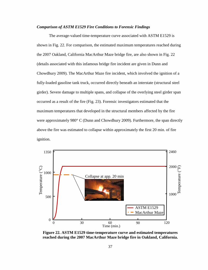
Figure 22. ASTM E1529 time-temperature curve and estimated temperatures reached
during the 2007 MacArthur Maze bridge fire in Oakland, California. ............ 37
Figure 23. Damage caused by MacArthur Maze fire (© 2007 California Department of
Transportation). ................................................................................................ 38
Figure 24. ASTM E1529 performance criteria for protected structural members exposed
to open-air hydrocarbon pool fires. .................................................................. 39
Figure 25. Location of Lime Kiln Lane overpass within the United States (source: Google
Maps). .............................................................................................................. 42
Figure 26. Location of Lime Kiln Lane overpass within Kentucky (source: Google Maps).
.......................................................................................................................... 43
Figure 27. Aerial view of bridge site (source: Google Maps). ......................................... 43
x
Figure 28. Structural configuration (excerpted from structural drawings). ...................... 45
Figure 29. Typical girder elevations (excerpted from structural drawings): a) Between
stiffeners; b) Diaphragm configurations. ......................................................... 46
Figure 30. Steel shoe (fixed) bearing details for bearings atop the central pier (excerpted
from structural drawings). ................................................................................ 47
Figure 31. Steel rocker (expansion) bearing details for bearings atop the end abutments
(excerpted from structural drawings). .............................................................. 48
Figure 32. Bearing layout atop the central pier................................................................. 48
Figure 33. Elevation of pier and footings (excerpted from structural drawings). ............. 49
Figure 34. Plan view of east end abutment (excerpted from structural drawings). .......... 51
Figure 35. FE Model of Lime Kiln Lane overpass (mesh not shown). ............................ 52
Figure 36. Element discretization of bridge pier and superstructure. ............................... 53
Figure 37. Plan view of shell element discretization for the reinforced concrete roadway
and lane shoulders (shell element thicknesses are shown)............................... 54
Figure 38. Isometric view of shell element discretization for the steel plate girders, web-
stiffeners, and diaphragms. .............................................................................. 54
Figure 39. Isometric view of external girder and end abutment diaphragm. .................... 55
Figure 40. Isometric view of solid element discretization for the reinforced concrete pier
and footings. ..................................................................................................... 55
xi
Figure 41. Isometric view of southernmost bearing pedestal atop pier cap of central pier
(mesh not shown). ............................................................................................ 56
Figure 42. Isometric view from beneath the central pier (mesh not shown). ................... 57
Figure 43. Isometric view of northernmost girder over end abutment (mesh not shown).58
Figure 44. Geometric modeling of fire protection materials as solid elements. ............... 59
Figure 45. Isometric view of bridge FE model with annotations of unprotected element
faces (mesh not shown). ................................................................................... 60
Figure 46. Effect of temperature on thermal conductivity of normal-strength concrete
(adapted from ENV 1995a). ............................................................................. 64
Figure 47. Effect of temperature on specific heat of normal-strength concrete (adapted
from ENV 1995a). ............................................................................................ 64
Figure 48. Effect of temperature on elastic modulus of structural steel (adapted from
FEMA 2002). ................................................................................................... 66
Figure 49. Effect of temperature on yield stress of structural steel (adapted from FEMA
2002). ............................................................................................................... 68
Figure 50. Effect of temperature on thermal conductivity of structural steel (adapted from
ENV 1995b). .................................................................................................... 69
Figure 51. Effect of temperature on specific heat of structural steel (adapted from ENV
1995b). ............................................................................................................. 70
Figure 52. Effect of temperature on thermal conductivity of refractory cement (adapted
from Morgan-Thermal Ceramics 2004). .......................................................... 72
xii
Figure 53. Effect of temperature on specific heat of refractory cement (adapted from
Morgan-Thermal Ceramics 2004). ................................................................... 72
Figure 54. Lime Kiln Lane overpass tank truck fire on I-71 N (June, 2011) (Photo ©
2011 WHAS11). ............................................................................................... 76
Figure 55. Girder damage caused by the Lime Kiln Lane overpass tank truck fire (west
view from east-end abutment). ......................................................................... 77
Figure 56. Position of tank truck along northbound I-71 right shoulder beneath Lime
Kiln Lane overpass. .......................................................................................... 79
Figure 57. Position of tank truck beneath Lime Kiln Lane overpass (facing toward the
east end abutment)............................................................................................ 79
Figure 58. Plan-view schematic of severe-fire scenario considered in the Lime Kiln Lane
overpass FE simulations. .................................................................................. 81
Figure 59. Mechanical and thermal loading of the Lime Kiln Lane overpass. ................. 85
Figure 60. Stage 1 of loading: prescribed mechanical loading. ........................................ 86
Figure 61. Stage 2 of loading: mechanical and thermal loading. ...................................... 87
Figure 62. Effect of gravity loads on bridge response: a) undeformed state; b) deflected
span shape (scale factor: 200). ......................................................................... 88
Figure 63. Von Mises stresses throughout elements of A36 structural steel members. ... 88
Figure 64. Bridge deflected shapes (scale factor: 1): a) Onset of thermal flux load; b) 5
min.; c) 10 min.; d) 12 min.; e) 13 min. ........................................................... 90

xiii
Figure 65. Von Mises stresses throughout elements of the deformed A36 structural steel
members (scale factor: 1): a) 10 min.; b) 12 min. ............................................ 91
Figure 66. Temperatures of A36 structural steel members (°C): a) 10 min.; b) 12 min. .. 93
Figure 67. Insulated bridge deflected shapes (scale factor: 1): a) Onset of thermal flux
load; b) 20 min. ................................................................................................ 94
Figure 68. Temperatures of A36 structural steel members (°C): a) 10 min.; b) 20 min. .. 95
Figure 69. Von Mises stresses throughout elements of the deformed A36 structural steel
members after 20 min. of fire exposure (scale factor: 1). ................................ 97
Figure 70. Insulated bridge deflected shapes (scale factor: 1): a) Onset of thermal flux
load; b) 20 min. ................................................................................................ 98
Figure 71. Temperatures of A36 structural steel members (°C): a) 10 min.; b) 20 min. .. 99
Figure 72. Von Mises stresses throughout elements of the deformed A36 structural steel
members after 20 min. of fire exposure (scale factor: 1). .............................. 100
xiv
LIST OF TABLES
Table 1. Relative material parameter values for structural steel member......................... 13
Table 2. Relative material parameter values for R/C member. ......................................... 17
Table 3. Concrete and mild steel reinforcement input parameters for the reinforced
concrete structural material model. .................................................................. 62
Table 4. Refractory cement input parameters for the structural material model. ............. 71
Table 5. Intumescent coating material model input parameters. ...................................... 73
Table 6. Maximum response parameters predicted in steel members. ........................... 101
xv
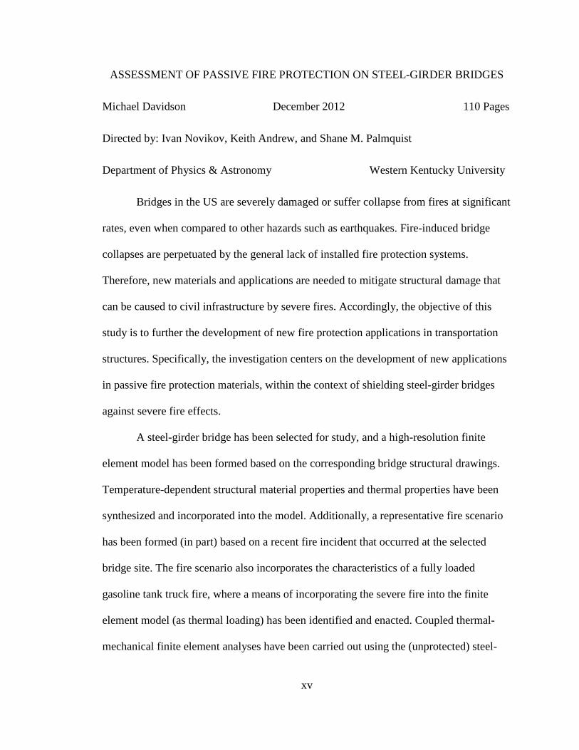
ASSESSMENT OF PASSIVE FIRE PROTECTION ON STEEL-GIRDER BRIDGES
Michael Davidson December 2012 110 Pages
Directed by: Ivan Novikov, Keith Andrew, and Shane M. Palmquist
Department of Physics & Astronomy Western Kentucky University
Bridges in the US are severely damaged or suffer collapse from fires at significant
rates, even when compared to other hazards such as earthquakes. Fire-induced bridge
collapses are perpetuated by the general lack of installed fire protection systems.
Therefore, new materials and applications are needed to mitigate structural damage that
can be caused to civil infrastructure by severe fires. Accordingly, the objective of this
study is to further the development of new fire protection applications in transportation
structures. Specifically, the investigation centers on the development of new applications
in passive fire protection materials, within the context of shielding steel-girder bridges
against severe fire effects.
A steel-girder bridge has been selected for study, and a high-resolution finite
element model has been formed based on the corresponding bridge structural drawings.
Temperature-dependent structural material properties and thermal properties have been
synthesized and incorporated into the model. Additionally, a representative fire scenario
has been formed (in part) based on a recent fire incident that occurred at the selected
bridge site. The fire scenario also incorporates the characteristics of a fully loaded
gasoline tank truck fire, where a means of incorporating the severe fire into the finite
element model (as thermal loading) has been identified and enacted. Coupled thermal-
mechanical finite element analyses have been carried out using the (unprotected) steel-
xvi
girder bridge model. An additional finite element simulation has been carried out, where
the steel-girder bridge model has been fitted with a refractory cement material that
insulates the underside of the bridge spans. Also, a finite element simulation has been
carried out where the steel-girder bridge model has been fitted with intumescent coating
material as insulation against fire effects.
Both the refractory cement and the intumescent coating materials have been found
to possess robust insulation characteristics from the simulation results. Namely, the finite
element analysis results indicate that, in the event of a bridge fire, both materials are
capable of preventing the buildup of damaging temperatures in underlying structural
members. Accordingly, the refractory cement and intumescent coating materials have
been identified as successful passive fire protection materials for the fire scenario and
bridge case considered.
1
INTRODUCTION
Commercial vehicles continually, and ubiquitously, frequent roadways throughout
the US transportation system. Significant portions of the US commercial trucking fleet, as
a necessity, transport combustible goods and flammable liquids (e.g., gasoline). As part
of the more than 1.6 trillion km traveled by commercial trucks in the US each year (RITA
2006), relatively more vulnerable civil infrastructure (e.g., bridges, tunnels) are traversed
numerous times every hour of every day. For each crossing, there exists the risk of a
vehicular accident. Alternatively, a commercial vehicle may be used as part of malicious
activities, and purposefully driven so as to directly collide with a transportation structure.
In the event that a commercial truck accident occurs within the vicinity of vulnerable
infrastructure, then the vehicle contents may subsequently ignite and, a severe fire may
develop. Consequently, said infrastructure can suffer damage, even at catastrophic levels
(i.e., to the point of collapse).
Among the environmental hazards faced by transportation structures such as
bridges, fire is among the most severe. Ham and Lockwood (2002) estimated that, for
hundreds of the 600,000 bridges located in the US, if an extreme event such as a severe
fire were to cause the collapse of one of these structures, high numbers of casualties and
substantial economic losses would be incurred. Roberts et al. (2003) estimated that
thousands of bridges, if catastrophically damaged, could result in high losses with respect
to both life and economy. Separately arrived at, yet similar, findings from the
aforementioned studies highlight a critical shortcoming, considering that the vast
majority of bridges are not capable of resisting severe fire conditions (Beard and Carvel
2005, Kodur et al. 2010).
2
Fire protection of bridge structures is in a fledgling state, where historically more
attention has been given to fire protection of buildings (Payá-Zaforteza and Garlock
2010). Consequently, the vast majority of bridges in the US do not contain passive fire
protection materials that are capable of withstanding temperatures associated with severe
fires, where temperatures can reach or exceed 1100° C (ASTM 2001). As a result,
bridges generally do not contain any fire protection beyond the resistance that is intrinsic
to constituent structural members. It is paramount that measures be taken to: 1) Mitigate
structural damage; and, 2) Prevent loss of integrity of bridges that may be subjected to
severe fire conditions.
More broadly, structural fire safety is the least developed area within fire science,
even though it has been asserted recently that fire safety should constitute a primary
consideration in civil infrastructure design (Kodur et al. 2007). Given that bridges
comprise a large, and necessary, portion of the US transportation system, the current
research pertains to the development of new applications in protecting bridges against
severe fires. More specifically, the current research focuses on establishing means of
enhancing the structural integrity of bridges through identification and assessment of
advanced materials that (when applied) shield new and existing bridge structural
members from elevated temperatures. Innovative and robust solutions for fire protection
of bridge structural members are proposed as part of the current research, based on an
understanding of the current state of the art in bridge structural response to fire and
existing fire protection capabilities. Specifically, fire protection materials that may be
suitable for wide-scale deployments in the protection of transportation structures against
severe fires are identified.
3
The efficacy of candidate fire protection materials are gauged in the current study
based on results obtained from conducting coupled thermal-mechanical finite element
analyses (FEA) on a selected bridge case. As a further qualification, the current study
analyses pertain to a steel-girder bridge finite element (FE) model, which is subjected to
severe fire loading under its current (i.e., unprotected) state of construction, and when
fitted (in the FE model) with various types of fire protection materials. Steel-girder
bridges are emphasized in the current study because this bridge type makes up more than
36% of the 600,000 US bridges (Galambos et al. 1993). The current study results are put
forth with the ultimate goal of collaborating with state agencies (i.e., those responsible for
maintaining US transportation networks) to assess and deploy successful fire protection
measures on vulnerable steel-girder bridges.
Fire-Safety Experiments and Analytical Studies for Bridges
Generally, bridge design codes and standards (in contrast to building codes and
tunnel fire safety standards) do not take into account the concept of fire safety (Kodur et
al. 2010). Consequently, research efforts in the area of fire safety have not generally
focused on improving the understanding of bridge fires or the fire protection levels of
bridge structural members. However, recent high-profile incidents of bridge fires (e.g.,
the Nine Mile Bridge Fire, discussed later) have prompted forensic studies of bridge fire
phenomena (e.g., Stoddard 2004, Astaneh-Asl et al. 2009, Dunn and Chowdhury 2009).
Non-forensic studies that have been carried out in the area of bridge fire safety are
extremely scarce. Specifically, non-forensic studies relevant to bridge fire phenomena
and passive protection of bridge structural members are summarized below. Additionally,
pertinent ongoing studies are reviewed.
4
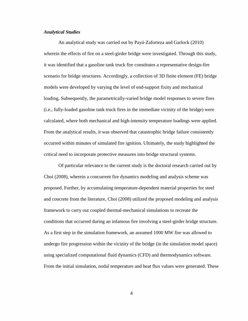
Analytical Studies
An analytical study was carried out by Payá-Zaforteza and Garlock (2010)
wherein the effects of fire on a steel-girder bridge were investigated. Through this study,
it was identified that a gasoline tank truck fire constitutes a representative design-fire
scenario for bridge structures. Accordingly, a collection of 3D finite element (FE) bridge
models were developed by varying the level of end-support fixity and mechanical
loading. Subsequently, the parametrically-varied bridge model responses to severe fires
(i.e., fully-loaded gasoline tank truck fires in the immediate vicinity of the bridge) were
calculated, where both mechanical and high-intensity temperature loadings were applied.
From the analytical results, it was observed that catastrophic bridge failure consistently
occurred within minutes of simulated fire ignition. Ultimately, the study highlighted the
critical need to incorporate protective measures into bridge structural systems.
Of particular relevance to the current study is the doctoral research carried out by
Choi (2008), wherein a concurrent fire dynamics modeling and analysis scheme was
proposed. Further, by accumulating temperature-dependent material properties for steel
and concrete from the literature, Choi (2008) utilized the proposed modeling and analysis
framework to carry out coupled thermal-mechanical simulations to recreate the
conditions that occurred during an infamous fire involving a steel-girder bridge structure.
As a first step in the simulation framework, an assumed 1000 MW fire was allowed to
undergo fire progression within the vicinity of the bridge (in the simulation model space)
using specialized computational fluid dynamics (CFD) and thermodynamics software.
From the initial simulation, nodal temperature and heat flux values were generated. These
5
values were then prescribed in initializing a corresponding bridge FE model, which was
subsequently subjected to coupled thermal-mechanical FEA.
In the current study, portions of the analytical framework proposed by Choi
(2008) will be utilized in a new manner, where coupled thermal-mechanical FEA will be
carried out on a steel-girder bridge structure with the express purpose of assessing the
robustness of passive fire protection materials that are installed on steel-girder bridges.
More specifically, the heat flux associated with a severe-fire scenario will be introduced
into a FE steel-girder bridge model under both the as-built (i.e., unprotected) and multiple
passively protected configurations. The (as-built and protected) bridge response to fire
will subsequently be quantified for each simulation, and those fire protection materials
that are of the greatest efficacy will be identified.
Ongoing Studies
Although bridge fire safety is a relatively new field, research momentum is
increasing within the areas of assessing bridge fire hazard levels. Namely, National
Cooperative Highway Research Project (NCHRP) 12-85 Highway Bridge Fire Hazard
Assessment has recently been undertaken. Although no physical testing or fire
simulations fall within the scope of the NCHRP study, the project outcomes include: 1)
Determination of the susceptibility to fire damage for highway bridges; 2) Development
of damage assessment and repair techniques in the form of guidelines; and, 3)
Development of guidelines that facilitate reductions in fire damage risk. The NCHRP
study findings will provide a valuable resource towards the assessment of candidate
bridge fire-protection solutions.
6
Scope of Research
The current research has been undertaken given the general lack of studies that
have previously been carried out with emphasis on bridge fire-safety. Furthermore, the
current study is motivated by the Department of Homeland Security (DHS) and Office of
Infrastructure Protection (IP) DHS/IP Capability Gap Statement: 2008-012-
Transportation, wherein it is stated that:
The overall objective is to develop new materials, or new application methods for existing materials, that will protect transportation-related infrastructure elements from high intensity fires, such as those caused by fuel sources or explosions.
The current study specifically facilitates the development of passive fire
protection material applications that can be used in the protection of steel-girder bridges
against severe fires. The contents of this report detail findings from completing the
following three major tasks:
1. Conduct an extensive literature review concerning the state of the art in fire protection of steel-girder bridges;
2. Identify needs areas pertaining to the understanding of, and protection against, severe fire loading on steel-girder bridges; and,
3. Select a steel-girder bridge, form a bridge FE model, and conduct analytical assessments that measure bridge response to severe fire loads when fitted with various levels of passive fire protection.
Task 1, listed above, is satisfied by reviewing available literature related to current levels
of protection in steel-girder bridges, identifying currently available fire protection
materials that are feasible in large-scale deployments, and exploring the effect of
increased temperatures on commonly occurring structural members within steel-girder
bridges. Findings from Task 1 enable the identification of needs areas in fire safety
design for steel-girder bridges, in association with Task 2. Needs areas identified as part
7
of Task 2 motivate the selection of critical model input characteristics (e.g., fire size,
location, and distribution; properties of protective materials) for the analytical assessment
of a selected steel-girder bridge, where bridge performance is investigated using FEA,
under severe-fire conditions. Finally, successful fire protection materials are identified for
the selected bridge case based on the fire-exposure response of the bridge, particularly
when it is fitted (in the FE model) with various types of fire protection materials.
8
BEHAVIOR OF STRUCTURAL AND FIRE-PROTECTION MATERIALS WHEN SUBJECTED TO ELEVATED
TEMEPRATURES
Structural steel and concrete are the two most commonly used materials in
transportation structures. When exposed to severe fire conditions, both steel and concrete
portions of transportation structures have been observed to undergo severe material
degradations with respect to material properties observed under ambient conditions (e.g.,
FEMA 2002 for steel, Ulm et al. 1999a-b for concrete). In steel-girder bridges, the
primary load-carrying superstructure members (i.e., the girders) are comprised of
structural steel and form the shape of an “I” in cross-section, while the overlying bridge
roadway (i.e., the surface which vehicles utilize) consists of reinforced concrete.
Therefore, both steel and concrete behavior under elevated temperatures is of interest in
the current study.
Substantial differences have been observed to occur between elevated-
temperature behavior of steel and concrete structural assemblies. Valuable insights into
structural fire response can, therefore, be derived from investigating the effects of
elevated temperature on steel and concrete at the material level, and also from
investigating structural members comprised of (separately) structural steel and reinforced
concrete. Accordingly, both material responses and motions calculated as part of a
preliminary finite-element (FE) based investigation into the response of steel and
reinforced concrete (at the member level) are presented below.
9
Structural Steel and Concrete at the Material Level
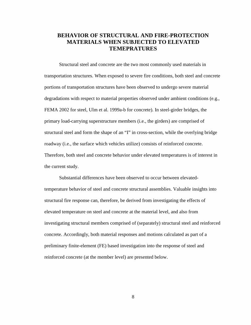
Steel is a ductile, non-porous material, and therefore tends to undergo relatively
more continuous degradations in structural properties under increasing temperatures. As
shown in Fig. 1, the yield stress of structural steel at temperature i (fy,i) is generally less
than the corresponding yield stress that would be observed under ambient conditions
(fy,o). Losses in stiffness follow a similar overall trend to that observed for yield-stress
capacity (FEMA 2002). Note that commonly accepted critical temperatures for steel
structural members range from approximately 400° C to 600° C (FEMA 2002).
Consequently, it is critical that fire protection schemes be capable of preventing the
buildup of steel structural assembly temperatures to values of approximately 400° C.
400 800
32 400
0.8
0.6
0.4
0.2
1.0
0.00
Temperature ( C)200 600
Temperature ( F)800 1200
Ultimate compressive strength of plain concrete
Rel
ativ
e St
reng
th
Yield stress of structural steel
f’c,
i/f’ c,
oor
f y,i/f
y,o
Structural steelPlain concrete
Figure 1. Relative levels of material strength parameters (Davidson et al. 2012).
10
Also shown in Fig. 1 (above) are relative levels of concrete compressive strength
at temperature i (f’c,i) with respect to ambient-condition compressive strength (f’c,o). In
contrast to structural steel, concrete is capable of maintaining relatively high levels of
ultimate compressive strength at temperatures up to approximately 600° C before
suddenly undergoing severe degradations (FEMA 2002).
Spalling Effects of Concrete
Concrete (in contrast to structural steel) is a brittle, porous material, and therefore,
subject to spalling when rapidly heated, where spalling is the potentially violent flaking
away of layers of concrete material. When fire-induced spalling occurs in regions of
concrete structural members that contain steel reinforcement, the reinforcement is then
left directly exposed to adverse fire conditions. As a result, sudden catastrophic failures
can occur at temperatures ranging from 200° C (Beard and Carvel 2005) to
approximately 380° C (Hertz 2003).
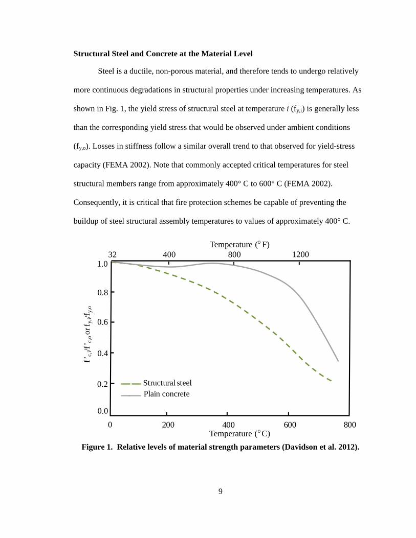
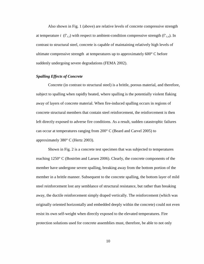
Shown in Fig. 2 is a concrete test specimen that was subjected to temperatures
reaching 1250° C (Boström and Larsen 2006). Clearly, the concrete components of the
member have undergone severe spalling, breaking away from the bottom portion of the
member in a brittle manner. Subsequent to the concrete spalling, the bottom layer of mild
steel reinforcement lost any semblance of structural resistance, but rather than breaking
away, the ductile reinforcement simply draped vertically. The reinforcement (which was
originally oriented horizontally and embedded deeply within the concrete) could not even
resist its own self-weight when directly exposed to the elevated temperatures. Fire
protection solutions used for concrete assemblies must, therefore, be able to not only
11
prevent the buildup of temperatures to material-critical levels (for both the concrete and
embedded steel reinforcement), but also must act to prevent concrete spalling effects.
Figure 2. Severe spalling of reinforced concrete member after exposure to elevated
temperatures (Boström and Larsen 2006).
Illustration of Temperature Effects on Structural Members from Transportation Structures using Finite Element Analysis (FEA)
Given the substantial differences observed between elevated-temperature
behavior for steel and concrete at the material level, it follows that further insights into
structural response to fire can be derived from investigating the effects of elevated
temperature on structural assemblies comprised of these two materials. Such insights can
then be used to direct the selection of candidate passive fire protection materials that are
suitable for steel-girder bridges. Accordingly, results obtained from a preliminary finite-
element based investigation into the response of steel at the member level (i.e., a steel
girder) are presented below. Given the added complexities associated with simulating
12
thin, reinforced concrete member (e.g., response of reinforced concrete roadway slabs),
this task is reserved for the full, selected bridge case analyses.
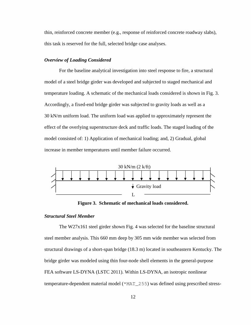
Overview of Loading Considered
For the baseline analytical investigation into steel response to fire, a structural
model of a steel bridge girder was developed and subjected to staged mechanical and
temperature loading. A schematic of the mechanical loads considered is shown in Fig. 3.
Accordingly, a fixed-end bridge girder was subjected to gravity loads as well as a
30 kN/m uniform load. The uniform load was applied to approximately represent the
effect of the overlying superstructure deck and traffic loads. The staged loading of the
model consisted of: 1) Application of mechanical loading; and, 2) Gradual, global
increase in member temperatures until member failure occurred.
L
Gravity load
30 kN/m (2 k/ft)
Figure 3. Schematic of mechanical loads considered.
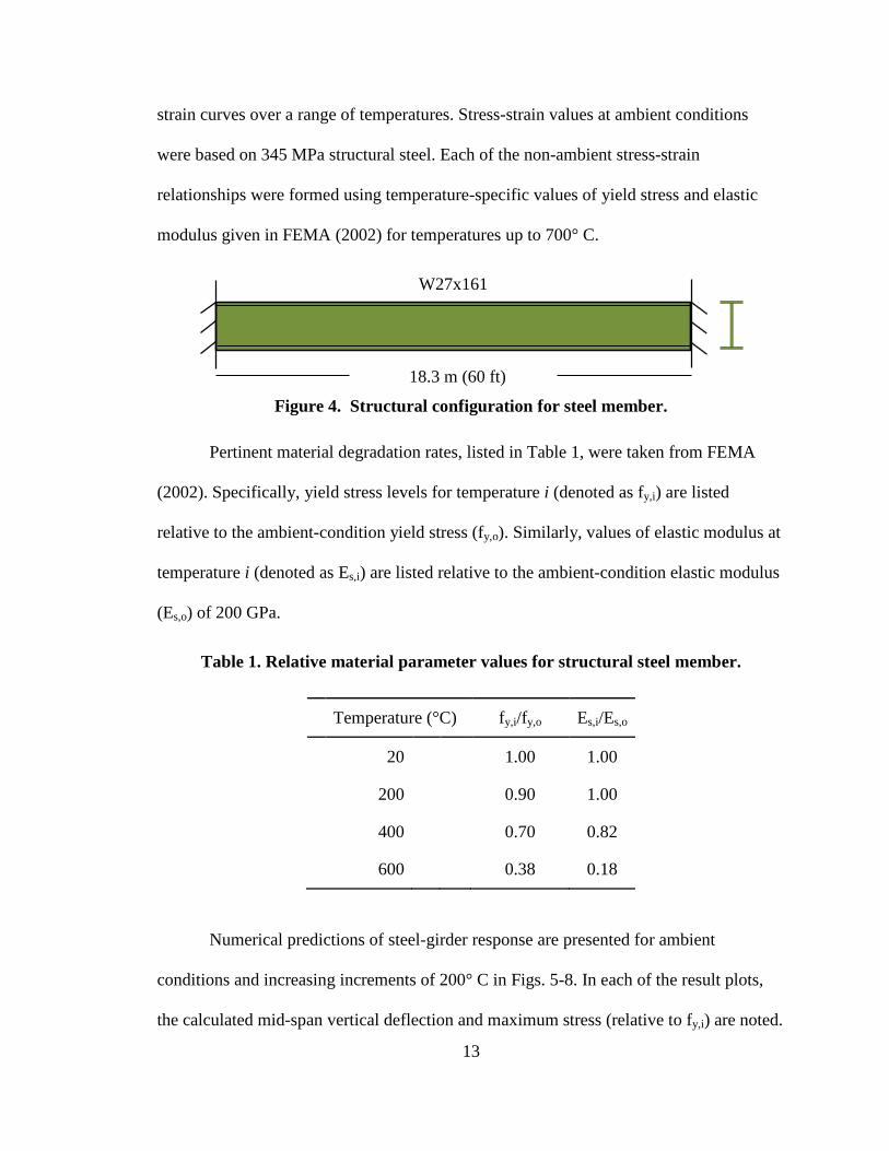
Structural Steel Member
The W27x161 steel girder shown Fig. 4 was selected for the baseline structural
steel member analysis. This 660 mm deep by 305 mm wide member was selected from
structural drawings of a short-span bridge (18.3 m) located in southeastern Kentucky. The
bridge girder was modeled using thin four-node shell elements in the general-purpose
FEA software LS-DYNA (LSTC 2011). Within LS-DYNA, an isotropic nonlinear
temperature-dependent material model (*MAT_255) was defined using prescribed stress-
13
strain curves over a range of temperatures. Stress-strain values at ambient conditions
were based on 345 MPa structural steel. Each of the non-ambient stress-strain
relationships were formed using temperature-specific values of yield stress and elastic
modulus given in FEMA (2002) for temperatures up to 700° C.
18.3 m (60 ft)
W27x161
Figure 4. Structural configuration for steel member.
Pertinent material degradation rates, listed in Table 1, were taken from FEMA
(2002). Specifically, yield stress levels for temperature i (denoted as fy,i) are listed
relative to the ambient-condition yield stress (fy,o). Similarly, values of elastic modulus at
temperature i (denoted as Es,i) are listed relative to the ambient-condition elastic modulus
(Es,o) of 200 GPa.
Table 1. Relative material parameter values for structural steel member.
Temperature (°C) fy,i/fy,o Es,i/Es,o
20
1.00 1.00
200
0.90 1.00
400
0.70 0.82
600
0.38 0.18
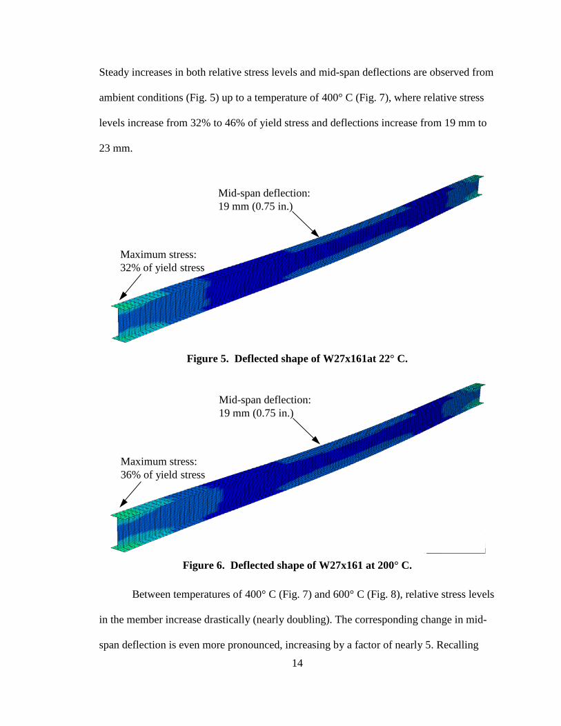
Numerical predictions of steel-girder response are presented for ambient
conditions and increasing increments of 200° C in Figs. 5-8. In each of the result plots,
the calculated mid-span vertical deflection and maximum stress (relative to fy,i) are noted.
14
Steady increases in both relative stress levels and mid-span deflections are observed from
ambient conditions (Fig. 5) up to a temperature of 400° C (Fig. 7), where relative stress
levels increase from 32% to 46% of yield stress and deflections increase from 19 mm to
23 mm.
Mid-span deflection: 19 mm (0.75 in.)
Maximum stress: 32% of yield stress
Figure 5. Deflected shape of W27x161at 22° C.
Mid-span deflection: 19 mm (0.75 in.)
Maximum stress: 36% of yield stress
Figure 6. Deflected shape of W27x161 at 200° C.
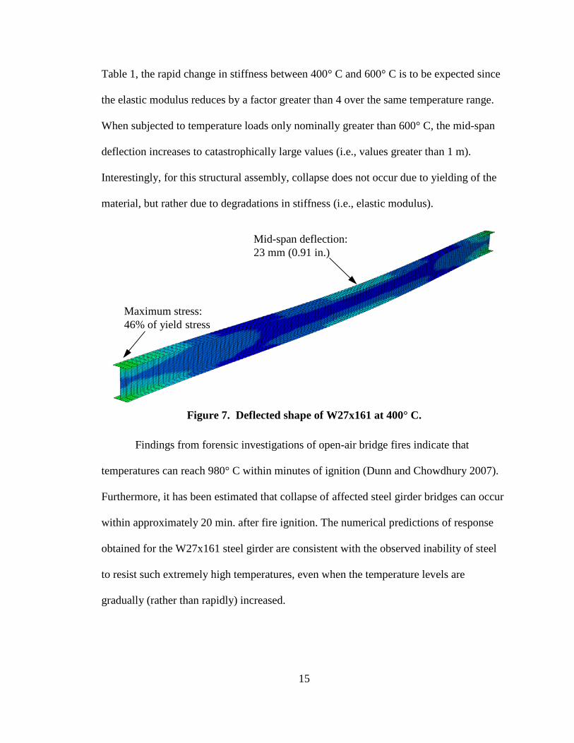
Between temperatures of 400° C (Fig. 7) and 600° C (Fig. 8), relative stress levels
in the member increase drastically (nearly doubling). The corresponding change in mid-
span deflection is even more pronounced, increasing by a factor of nearly 5. Recalling
15
Table 1, the rapid change in stiffness between 400° C and 600° C is to be expected since
the elastic modulus reduces by a factor greater than 4 over the same temperature range.
When subjected to temperature loads only nominally greater than 600° C, the mid-span
deflection increases to catastrophically large values (i.e., values greater than 1 m).
Interestingly, for this structural assembly, collapse does not occur due to yielding of the
material, but rather due to degradations in stiffness (i.e., elastic modulus).
Mid-span deflection: 23 mm (0.91 in.)
Maximum stress: 46% of yield stress
Figure 7. Deflected shape of W27x161 at 400° C.
Findings from forensic investigations of open-air bridge fires indicate that
temperatures can reach 980° C within minutes of ignition (Dunn and Chowdhury 2007).
Furthermore, it has been estimated that collapse of affected steel girder bridges can occur
within approximately 20 min. after fire ignition. The numerical predictions of response
obtained for the W27x161 steel girder are consistent with the observed inability of steel
to resist such extremely high temperatures, even when the temperature levels are
gradually (rather than rapidly) increased.
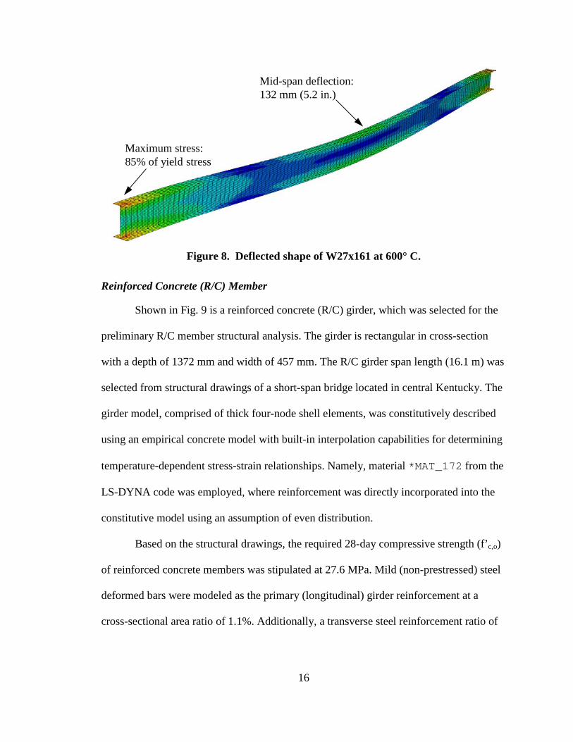
16
Mid-span deflection: 132 mm (5.2 in.)
Maximum stress: 85% of yield stress
Figure 8. Deflected shape of W27x161 at 600° C.
Reinforced Concrete (R/C) Member
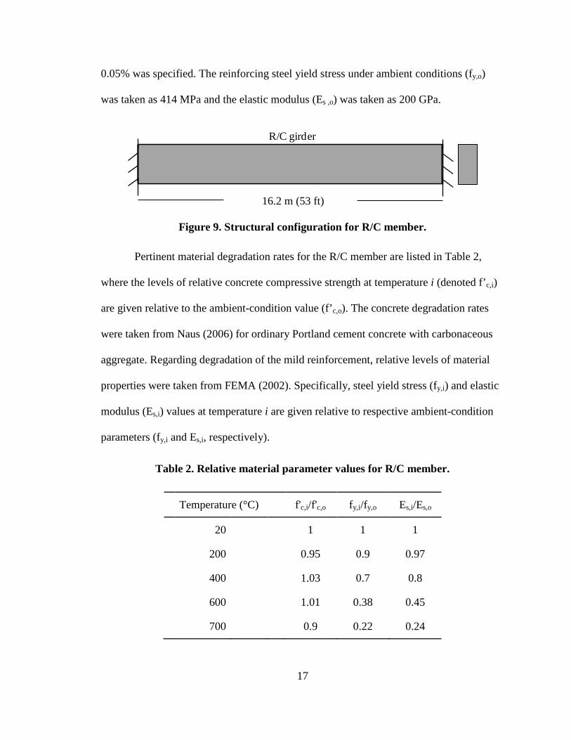
Shown in Fig. 9 is a reinforced concrete (R/C) girder, which was selected for the
preliminary R/C member structural analysis. The girder is rectangular in cross-section
with a depth of 1372 mm and width of 457 mm. The R/C girder span length (16.1 m) was
selected from structural drawings of a short-span bridge located in central Kentucky. The
girder model, comprised of thick four-node shell elements, was constitutively described
using an empirical concrete model with built-in interpolation capabilities for determining
temperature-dependent stress-strain relationships. Namely, material *MAT_172 from the
LS-DYNA code was employed, where reinforcement was directly incorporated into the
constitutive model using an assumption of even distribution.
Based on the structural drawings, the required 28-day compressive strength (f’c,o)
of reinforced concrete members was stipulated at 27.6 MPa. Mild (non-prestressed) steel
deformed bars were modeled as the primary (longitudinal) girder reinforcement at a
cross-sectional area ratio of 1.1%. Additionally, a transverse steel reinforcement ratio of
17
0.05% was specified. The reinforcing steel yield stress under ambient conditions (fy,o)
was taken as 414 MPa and the elastic modulus (Es ,o) was taken as 200 GPa.
16.2 m (53 ft)
AASHTO Type IIR/C girder
Figure 9. Structural configuration for R/C member.
Pertinent material degradation rates for the R/C member are listed in Table 2,
where the levels of relative concrete compressive strength at temperature i (denoted f’c,i)
are given relative to the ambient-condition value (f’c,o). The concrete degradation rates
were taken from Naus (2006) for ordinary Portland cement concrete with carbonaceous
aggregate. Regarding degradation of the mild reinforcement, relative levels of material
properties were taken from FEMA (2002). Specifically, steel yield stress (fy,i) and elastic
modulus (Es,i) values at temperature i are given relative to respective ambient-condition
parameters (fy,i and Es,i, respectively).
Table 2. Relative material parameter values for R/C member.
Temperature (°C) f'c,i/f'c,o fy,i/fy,o Es,i/Es,o
20
1 1 1
200
0.95 0.9 0.97
400
1.03 0.7 0.8
600
1.01 0.38 0.45
700
0.9 0.22 0.24
18
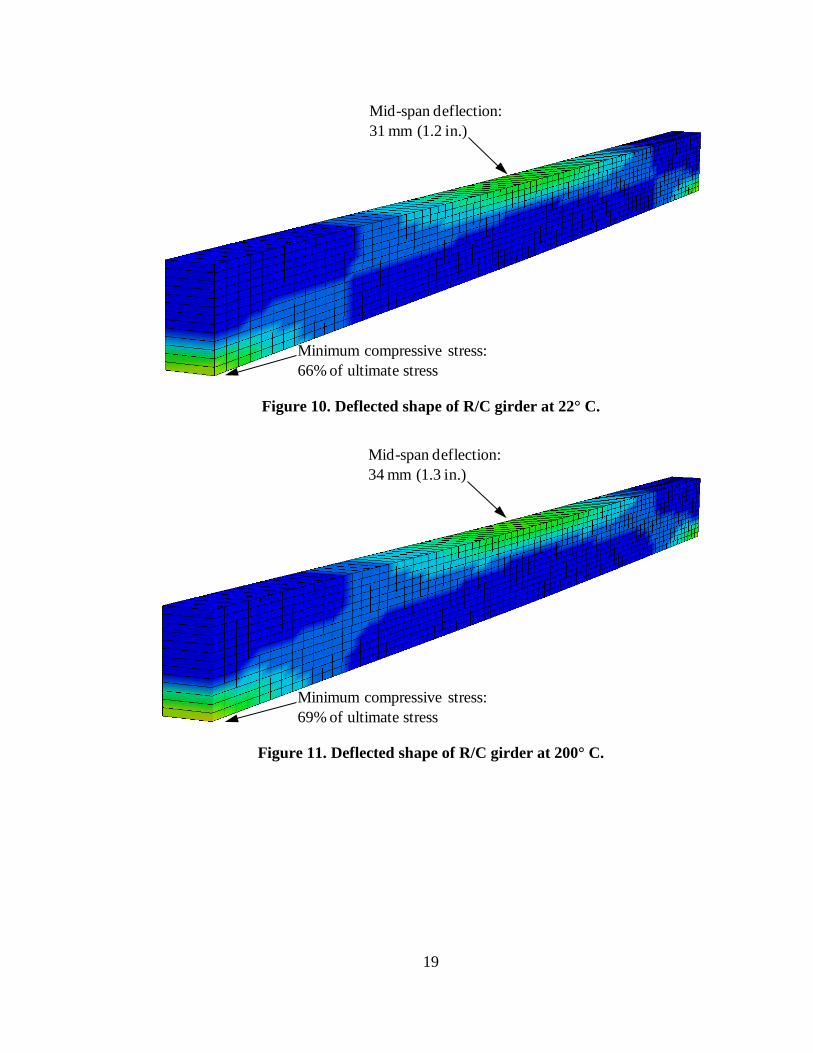
Predictions of R/C girder response for increasing temperature levels are presented
in Figs. 10-14. In each of the result plots, numerically determined mid-span vertical
deflection and minimum principal stress (relative to f'c,i) are noted. For temperatures up to
400° C (Fig. 12), only nominal increases are observed in the predictions of mid-span
deflection. In contrast, consistent with the high values of relative compressive strength
listed in Table 2, relative stress levels in the member decrease by approximately 10%
between 200° C (Fig. 10) and 600° C (Fig. 13). However, when the R/C girder is exposed
to temperatures above 600° C, significant increases in mid-span deflection are predicted.
Specifically, between exposures of 600° C and 700° C (Fig. 14), the mid-span deflection
increases by nearly fifty-percent.
The sudden increase in mid-span deflection can be attributed to: 1) The reduction
of the concrete material stiffness built into the constitutive material model; and, 2)
Substantial degradation in the steel material properties between 400° C and 600° C (recall
Table 2). Regarding item 2), the reinforcing steel properties are reduced by
approximately 50% over this temperature range. When subjected to temperatures greater
than 700° C, the mid-span deflections in the R/C member reach catastrophic levels,
where lack of member stiffness is primarily attributable to the degraded steel material
properties. Interestingly, the relative levels of concrete stress remain well below the
corresponding ultimate compressive strength values (f’ci) for temperatures less than 700°
C, where this phenomenon can be attributed to the extremely robust values of f'c,i/f'c,o
from Table 2.
19
Mid-span deflection:31 mm (1.2 in.)
Minimum compressive stress:66% of ultimate stress
Figure 10. Deflected shape of R/C girder at 22° C.
Mid-span deflection:34 mm (1.3 in.)
Minimum compressive stress:69% of ultimate stress
Figure 11. Deflected shape of R/C girder at 200° C.
20
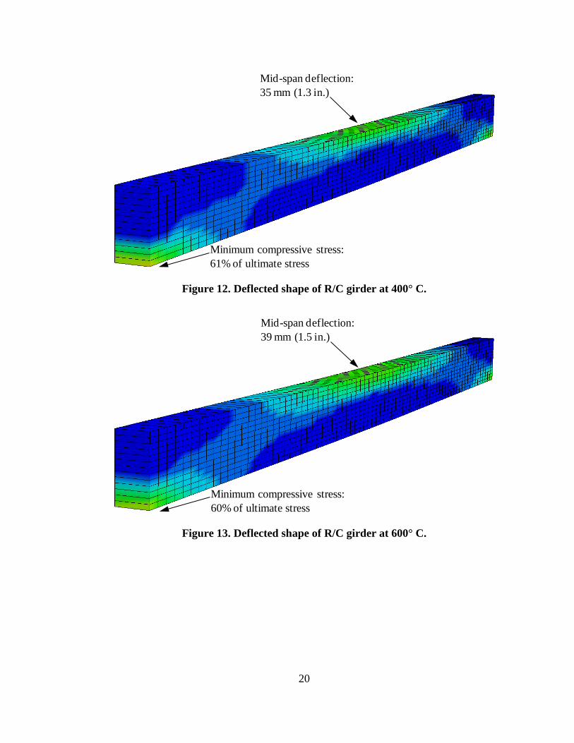
Mid-span deflection:35 mm (1.3 in.)
Minimum compressive stress:61% of ultimate stress
Figure 12. Deflected shape of R/C girder at 400° C.
Mid-span deflection:39 mm (1.5 in.)
Minimum compressive stress:60% of ultimate stress
Figure 13. Deflected shape of R/C girder at 600° C.
21
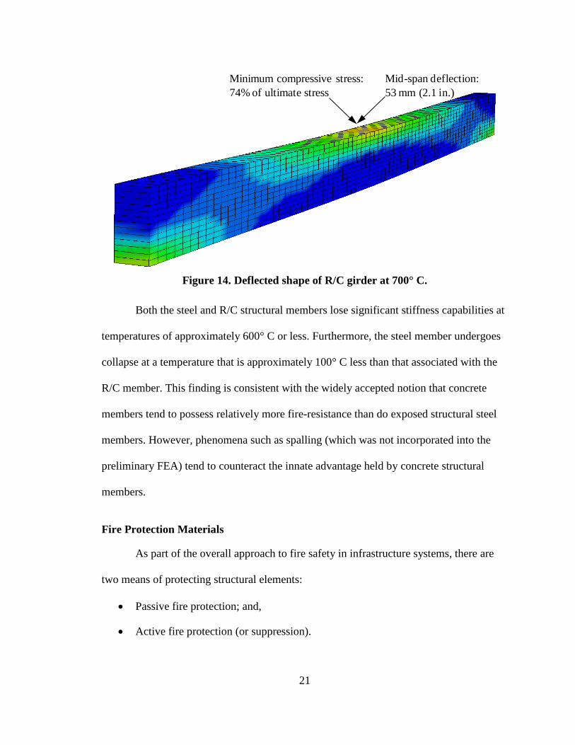
Mid-span deflection:53 mm (2.1 in.)
Minimum compressive stress:74% of ultimate stress
Figure 14. Deflected shape of R/C girder at 700° C.
Both the steel and R/C structural members lose significant stiffness capabilities at
temperatures of approximately 600° C or less. Furthermore, the steel member undergoes
collapse at a temperature that is approximately 100° C less than that associated with the
R/C member. This finding is consistent with the widely accepted notion that concrete
members tend to possess relatively more fire-resistance than do exposed structural steel
members. However, phenomena such as spalling (which was not incorporated into the
preliminary FEA) tend to counteract the innate advantage held by concrete structural
members.
Fire Protection Materials
As part of the overall approach to fire safety in infrastructure systems, there are
two means of protecting structural elements:
• Passive fire protection; and,
• Active fire protection (or suppression).
22
Within the context of steel-girder bridge fire safety, “passive fire protection” refers to
those insulating materials that can be applied to external faces of steel-girder bridge
members. The phrase “Active fire protection (or suppression)”, in contrast, refers to fire
suppression systems (e.g., water-mist), or monitoring and early-warning systems (e.g.,
closed-circuit camera networks, traffic control devices). The current research focuses on
the development of passive fire protection solutions (material applications) that can
feasibly be deployed to steel-girder bridges, and are capable of remaining effective even
when subjected to severe fire conditions.
Generally, there are three types of passive fire protection materials with
demonstrated potential for shielding the otherwise exposed faces of transportation
structures against high-intensity fires:
• Protective cladding;
• Refractory cements; and,
• Intumescent coatings.
The fire protection capabilities of these materials are discussed below in the context of
applicability to steel-girder bridges.
Protective Cladding
Cladding is made up of relatively thin (with thicknesses of less than app. 5.1 cm)
pre-engineered matrix panels. While cladding has been used historically for aesthetic
purposes in roadway tunnels (Beard and Carvel 2005), fire-resistant additives have since
been incorporated into the manufacturing process, and cladding systems have gained
traction in tunnel fire safety applications. While the exact makeup of commercially
available cladding panels remains proprietary, fire-resistant substances such as
23
vermiculite, calcium silicates, and fiberglass are commonly incorporated into the material
matrix (Beard and Carvel 2005).
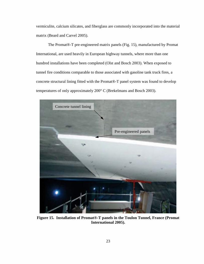
The Promat®-T pre-engineered matrix panels (Fig. 15), manufactured by Promat
International, are used heavily in European highway tunnels, where more than one
hundred installations have been completed (Olst and Bosch 2003). When exposed to
tunnel fire conditions comparable to those associated with gasoline tank truck fires, a
concrete structural lining fitted with the Promat®-T panel system was found to develop
temperatures of only approximately 200° C (Brekelmans and Bosch 2003).
Concrete tunnel lining
Pre-engineered panels
Figure 15. Installation of Promat®-T panels in the Toulon Tunnel, France (Promat
International 2005).
24
Prefabrication of panels offers a significant advantage in the deployment of
cladding systems for fire protection of tunnels (due to the presence of uniform tunnel
contours and passageway dimensions). However, the multiply contoured, non-uniform
member heights, depths, and widths found among steel-girders (in steel-girder bridges)
would present several challenges as part of cladding installations. Namely, many
different panel sizes would have to be cut for a given bridge of interest. Second,
installation of these panels would potentially be costly due to the necessity of installing
many different panel sizes. Furthermore, because many faces of varying widths would
necessarily be positioned perpendicular to, and abutting, one another, many panel edges
would have to be sealed using special, fire-resistant sealants. Therefore, it is not expected
that cladding systems will generally be suitable for steel-girder bridge fire protection
applications, and no further investigation into cladding systems is carried out in the
current study.
Refractory Cement
In contrast to substances such as Portland cement (which is commonly used in
structural concrete), refractory cements do not suffer from fire exposure susceptibilities
such as spalling or mechanical property degradation. Additionally, due to the inclusion of
substances such as vermiculite (Beard and Carvel 2005), refractory cements exposed to
fire tend to resist material temperature increases. Importantly, the addition of vermiculite
to refractory cement additionally mitigates the production of toxic gases, even over
prolonged fire exposure periods (Beard and Carvel 2005).
Refractory cements are typically spray-applied to fire-susceptible substrates in
relatively thin layers (less than 5.1 cm). Refractory cements have generally been used in
25
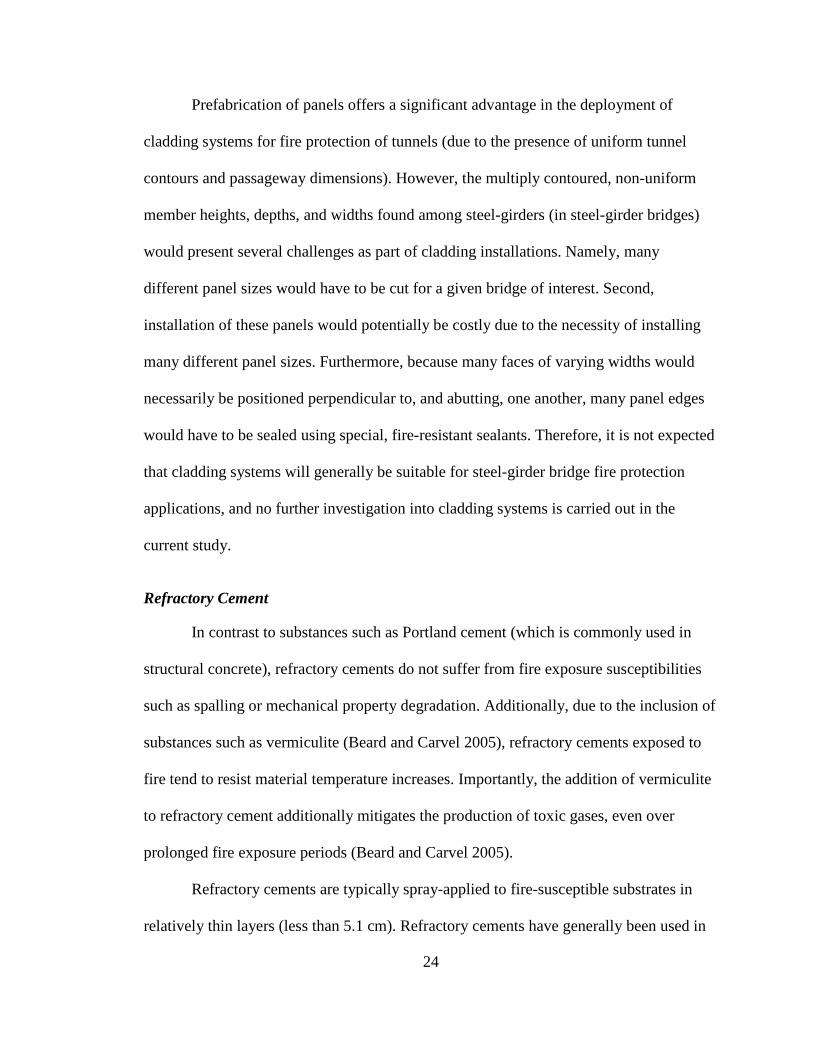
tunnel fire protection applicatons, where a sample installation is shown in Fig. 16 for the
FireBarrier 135TM refractory cement system. For a surface of interest, the installation
process involves the placement of an underlying welded-wire mesh (Fig. 16), which is
then sprayed over with the refractory cement material. Finally, the cementitious material
is troweled to the desired thickness, where increasing thickness correlates positively with
increased fire protection (Morgan-Thermal Ceramics 2004).
Figure 16. Installation of FireBarrierTM 135 system in tunnel lining (Davidson et al.
2012).
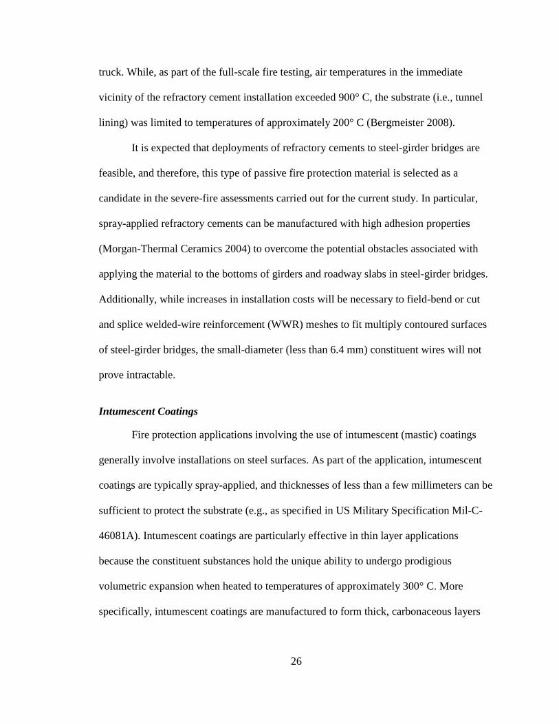
The FireBarrier TM 135 refractory cement system is unique in that it has been
assessed as part of full-scale tunnel fire tests (Bergmeister 2008). During testing, the
refractory cement system was installed in a 50 mm layer over a 4 m segment of tunnel
lining (located within the Virgolo tunnel, Italy). The installation was then directly
exposed to fire conditions associated with a combustible-goods carrying commercial
Welded-wire mesh
Refractory cement
26
truck. While, as part of the full-scale fire testing, air temperatures in the immediate
vicinity of the refractory cement installation exceeded 900° C, the substrate (i.e., tunnel
lining) was limited to temperatures of approximately 200° C (Bergmeister 2008).
It is expected that deployments of refractory cements to steel-girder bridges are
feasible, and therefore, this type of passive fire protection material is selected as a
candidate in the severe-fire assessments carried out for the current study. In particular,
spray-applied refractory cements can be manufactured with high adhesion properties
(Morgan-Thermal Ceramics 2004) to overcome the potential obstacles associated with
applying the material to the bottoms of girders and roadway slabs in steel-girder bridges.
Additionally, while increases in installation costs will be necessary to field-bend or cut
and splice welded-wire reinforcement (WWR) meshes to fit multiply contoured surfaces
of steel-girder bridges, the small-diameter (less than 6.4 mm) constituent wires will not
prove intractable.
Intumescent Coatings
Fire protection applications involving the use of intumescent (mastic) coatings
generally involve installations on steel surfaces. As part of the application, intumescent
coatings are typically spray-applied, and thicknesses of less than a few millimeters can be
sufficient to protect the substrate (e.g., as specified in US Military Specification Mil-C-
46081A). Intumescent coatings are particularly effective in thin layer applications
because the constituent substances hold the unique ability to undergo prodigious
volumetric expansion when heated to temperatures of approximately 300° C. More
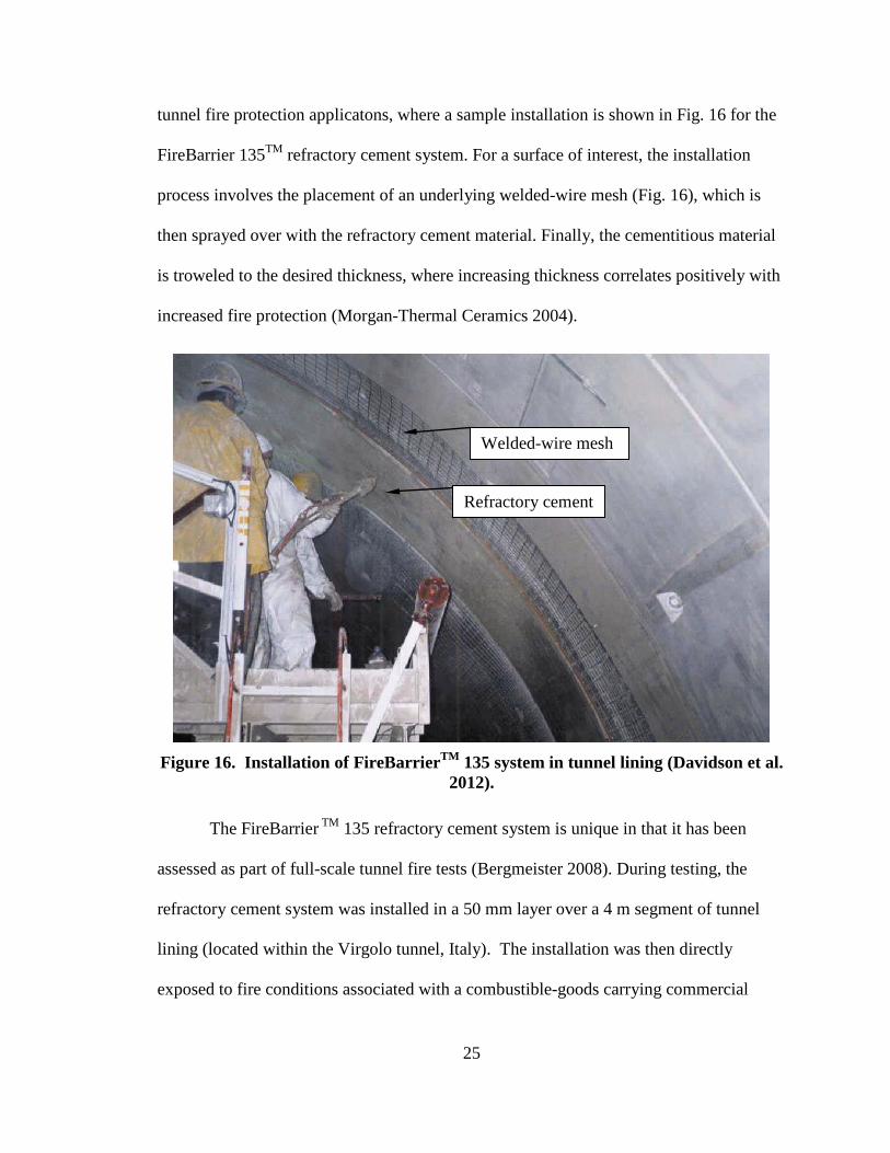
specifically, intumescent coatings are manufactured to form thick, carbonaceous layers
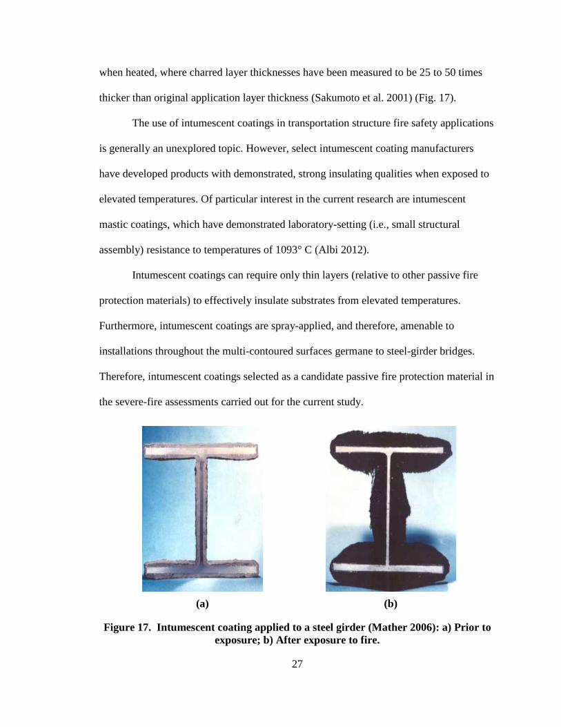
27
when heated, where charred layer thicknesses have been measured to be 25 to 50 times
thicker than original application layer thickness (Sakumoto et al. 2001) (Fig. 17).
The use of intumescent coatings in transportation structure fire safety applications
is generally an unexplored topic. However, select intumescent coating manufacturers
have developed products with demonstrated, strong insulating qualities when exposed to
elevated temperatures. Of particular interest in the current research are intumescent
mastic coatings, which have demonstrated laboratory-setting (i.e., small structural
assembly) resistance to temperatures of 1093° C (Albi 2012).
Intumescent coatings can require only thin layers (relative to other passive fire
protection materials) to effectively insulate substrates from elevated temperatures.
Furthermore, intumescent coatings are spray-applied, and therefore, amenable to
installations throughout the multi-contoured surfaces germane to steel-girder bridges.
Therefore, intumescent coatings selected as a candidate passive fire protection material in
the severe-fire assessments carried out for the current study.
(a)
(b)
Figure 17. Intumescent coating applied to a steel girder (Mather 2006): a) Prior to exposure; b) After exposure to fire.
28
NEEDS AREAS AND IMPACT OF FIRE ON STEEL-GIRDER BRIDGES
Fire Incidents
In comparison to the negative outcomes that can arise following environmental
hazard incidents such as earthquakes, bridges in the US are severely damaged or suffer
collapse from fires at significant rates. Specifically, over the period of 1989 to 2000, fires
led to the collapse of 16 bridges, whereas 17 bridges collapsed due to earthquakes over
the same period (Wardhana and Hadipriono 2003). Historically, bridge collapse rates
attributed to fire have been found to range from 3 to 4 times larger than those collapse
rates associated with seismic activity (Kodur et al. 2010, Harik et al. 1990).
Unfortunately, the area of bridge fire protection is in a fledgling state, where
bridges do not typically contain any fire protection beyond that provided by structural
members (Kodur et al. 2010). As discussed below, there are currently no specific
(prescriptive or performance-based) requirements explicitly dedicated to fire protection
of bridge structural members (Davidson et al. 2012). Moreover, only forensic findings are
currently available in facilitating the characterization of those conditions that arise during
severe bridge-fire incidents.
As an exacerbating factor in bridge fire-safety design, the geometric layouts and
structural configurations found among steel-girder bridges vary widely throughout the
US. It follows, therefore, that the potential levels of fire-exposure that can be attributed to
structural members also vary across the collective set of steel-girder bridges. Those
bridges facing the greatest risk (i.e., accounting for both the likelihood of critical-member
fire exposure, and the consequences of fire damage) should be identified, where this latter
29
task is reserved for future research efforts. The aforementioned shortcomings are
emphasized as part of a review of a recent bridge fire incident.
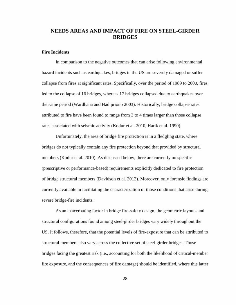
Nine Mile Road Fire (2009)
Shown in Fig. 18 is an aerial photograph taken shortly after the July 15, 2009
collision-induced explosion of a gasoline tank truck that occurred directly under the Nine
Mile Road I-75 overpass near Detroit, MI. Michigan State police indicated that a
passenger car that was going too fast around a curve on I-75 and Nine Mile Road at 8:20
p.m. crashed into a fuel tanker, causing an explosion. Witness statements indicate that
flames “shot hundreds of feet into the air”, while miraculously, there were no fatalities as
a result of this incident.
Figure 18. Explosive gasoline tank truck fire under the Nine Mile Road Bridge near
Detroit, Michigan in 2009.
The tanker, which crashed into the east pier (on the right-hand side of Fig. 18) of
the steel-girder overpass, carried approximately 49,000 l of gasoline and 15,000 l of
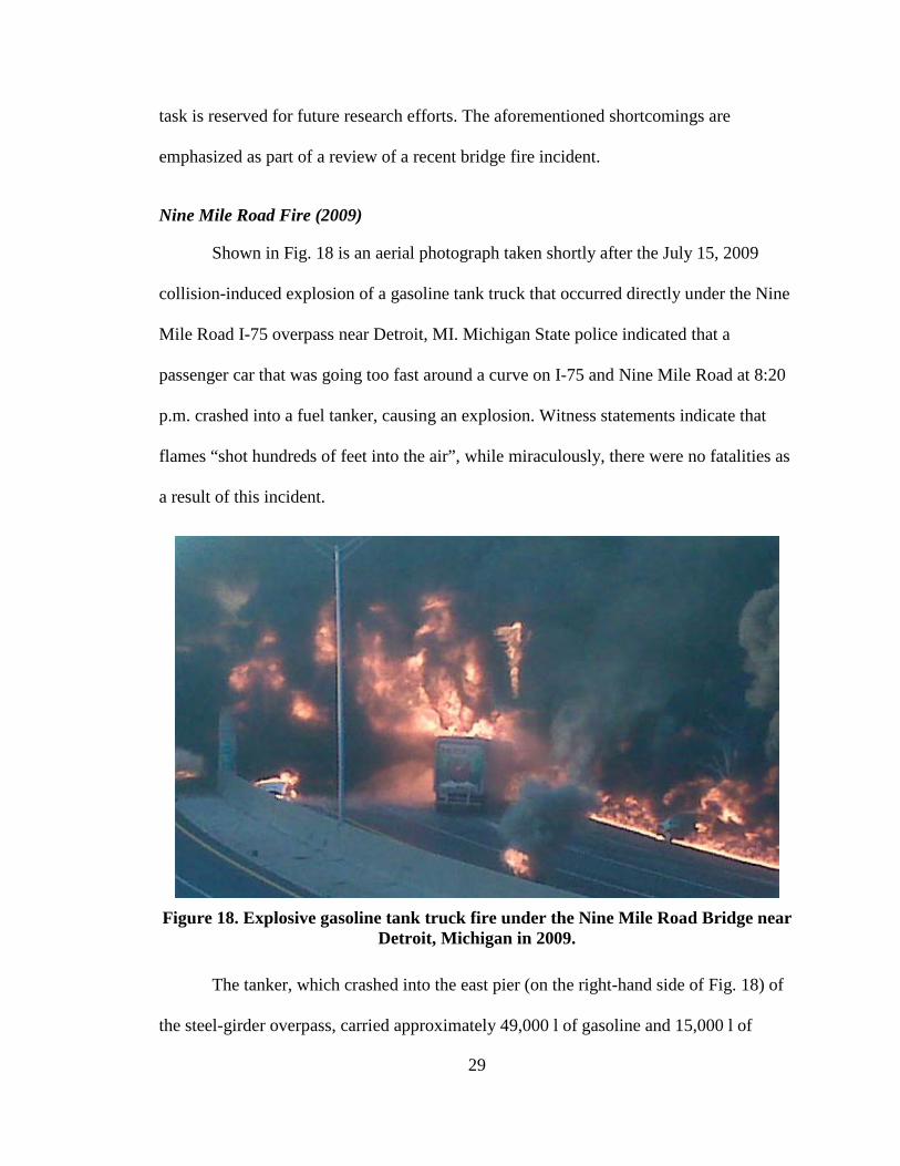
30
diesel fuel. The subsequent conflagration caused the I-75 overpass to completely collapse
within 30 min. (Kodur et al. 2010). The collapsed span, which was not fitted with any
passive fire protection, and final resting position of the gasoline tank truck, as viewed
from the southbound direction, are shown in Fig. 19. Note that from Fig. 18, the entire
span (and beyond) is engulfed in flames, and the sustained direct flame exposure of the
entire span is consistent with the full span charring seen in Fig. 19. Conservatively, this
bridge span could be stated to have undergone global severe-fire loading.
Figure 19. Collapsed Nine Mile Road bridge after explosive fire near Detroit,
Michigan in 2009 (Kodur et al. 2010).
As a critical shortcoming in the design of steel-girder bridges for fire safety, only
the forensic findings are available in facilitating determination of representative (i.e.,
design-based) severe fire conditions. As a consequence, no standardized means of
designing bridges to resist severe-fire effects is available. From the Nine Mile Road
31
bridge collapse forensic investigation, the quantity of fuel, and the time to collapse have
been surmised. However, no information is available regarding: 1) The fire signature or
the maximum temperatures reached; or, 2) Those regions of the overpass which face the
greatest fire exposure risk.
Explosive Effects
As an additional, severe shortcoming, the performance of fire protection
materials, when applied to bridge structural assemblies and subjected to blast pressures,
remains unknown. Of primary concern is that the initial blast from explosive gasoline
tank truck fires may render ineffective any fire protection material that has been applied
to bridge structural members. In the event that fire protection material is dispersed by the
blast wave, the bridge structural member is made vulnerable to all subsequent fire effects.
Extremely limited data, concerning the blast pressures associated with explosive
gasoline tank truck fires, are available from the literature. Purcell and Shatzer (2005)
carried out a series of blast tests for the Department of Justice, Bureau of Tobacco,
Firearms and Explosives in which gasoline tank trucks with various fuel loads were
ignited in an explosive manner. As part of the test program, Purcell and Shatzer (2005)
measured blast pressures and recorded physical damage on “witness vehicles” (i.e.,
passenger vehicles placed nearby) for tanker fuel loads ranging from 16,277 l to 34,070 l.
However, the performance of structural assemblies (e.g., bridge piers, girders) did not fall
within the scope of these tests. Fire protection applications developed as part of the
current infrastructure fire-safety research must demonstrate acceptable resistance to the
blast pressures associated with gasoline tank truck explosions, where this task is reserved
for future study.
32
Fire Protection Standards
From a legalistic standpoint, provisions are available in the National Fire
Protection Association (NFPA) Standard for Road Tunnels, Bridges, and Other Limited
Access Highways 2011 Edition (NFPA 2011) that explicitly pertain to the fire-safety
design of bridges. However, as shown in Fig. 20, the extent to which these provisions can
be used to (for a given bridge) quantify fire risk, identify members facing the greatest
potential for fire exposure, determine a fire signature, identify candidate fire protection
solutions, and recommend methodologies for assessing candidate fire protection
strategies is severely limited. Namely, only a general requirement is found among the
limited provisions (NFPA 2011):
Critical structural members shall be protected from collisions and high-temperature exposure that can result in dangerous weakening or complete collapse of the bridge or elevated highway.
Given the lack of developed bridge fire-safety design standards, bridges are generally
designed and constructed with no explicit fire protection, or only a level of fire resistance
that is supplied intrinsically by the structural members.
Design-Fires for Bridges
While no specific guidance related to determination of design-fire signatures are
given in the NFPA 502 tentative standards (NFPA 2011), it has been recognized that
ignition of a large-pool hydrocarbon fire (i.e., a gasoline tank truck fire) in the vicinity of
an occupied bridge constitutes a representative design-fire scenario for bridge structures
(Payá-Zaforteza and Garlock 2010). Furthermore, relevant structural assembly testing
standards are available, which provide time-temperature and heat release rate
33
relationships associated with large hydrocarbon pool fires that can occur within the
vicinity of bridge structures. However, it is critical to note that testing standards (e.g.,
those produced by ASTM) are limited in scope relative to more general design standards,
and therefore, significant efforts will be required (as part of future research efforts) to
integrate fire characteristics from testing standards into bridge fire protection design
provisions.
(a)
(b)
Figure 20. NFPA 502 fire protection standard: (a) Cover; (b) Chapter 6: Bridges and Elevated Highways.
Testing standards are used to measure and describe the response of materials,
products, or assemblies to heat and flame under controlled conditions, but do not
incorporate all factors required for fire hazard or fire risk assessment of the materials,
products, or assemblies. By carrying out fire-testing on protected bridge structural
34
assemblies, where the fire conditions specified in the testing standards are employed,
design guidelines can be developed to aid in effective fire protection of bridges.
Ultimately, fire conditions specified in the relevant testing standards and the desirable
characteristics of bridge fire protection systems (identified through fire-testing or
simulation) can be incorporated into more general bridge fire-protection standards, where
development of these standards should be explored as part of future research efforts.
ASTM E1529
One testing standard with strong potential for use in assessing passive fire
protection of steel-girder bridges is the ASTM E1529 (ASTM 2001) standard test method
for Determining Effects of Large Hydrocarbon Pool Fires on Structural Members and
Assemblies (Fig. 21). The ASTM E1529 standard contains testing instructions for
measuring the performance of structural members when exposed to large, free-burning
(i.e., open-air) fluid-hydrocarbon-fueled pool fires, where (as stated above) this type of
fire has been recognized as the most severe fire threat faced by bridge structures. The
intent of the ASTM E1529 testing standard is to provide a means of indicating whether
structural members of assemblies will continue to perform their intended function during
the period of fire exposure.
Although the ASTM E1529 standard was written primarily to aid in assessing the
performance of structural members within hydrocarbon processing industry (HPI)
facilities, the testing standard also extends to other facilities subject to large free-burning
hydrocarbon pool fires (e.g., bridge structures). Since structural members comprising HPI
facilities are commonly constructed using structural steel, the ASTM E1529 standard is
replete with instructions that are most relevant to structural steel members. However, as
35
stated in Section 16.2.1 and Section 17.3 of ASTM E1529, the testing procedures can be
used for the testing of members composed of other materials provided that appropriate
fire performance criteria have been established and substantiated. Stated alternatively, the
testing procedures set forth in ASTM E1529 can be used in testing structural assemblies
not comprised of structural steel given that the failure conditions for the non-steel
members (e.g., reinforced concrete roadway slabs of steel-girder bridges) have been
clearly and justifiably defined.
Figure 21. ASTM E1529 Standard test method for large free-burning hydrocarbon
pool fires.
As defined in Section 12 of ASTM E1529, structural assemblies containing fire
protection materials (i.e., protected test specimens) should be representative of the
construction for which classification is desired as to materials, workmanship, and details
such as the dimensions of various components. Furthermore, the test specimens should be
36
built (or modeled) under conditions representative of those encountered in actual
construction to the extent possible. Additionally, physical properties of materials and
components comprising the test specimen should be measured to account for material
property variability. Following construction of test specimens (including accounting for
the levels of moisture, solvents, plasticizers, curing compounds, or similar agents
expected to be present), the specimen should be conditioned prior to fire-testing with the
objective of providing a condition within the test specimen which is representative of the
intended end-use environment for the assembly.
Fire Conditions
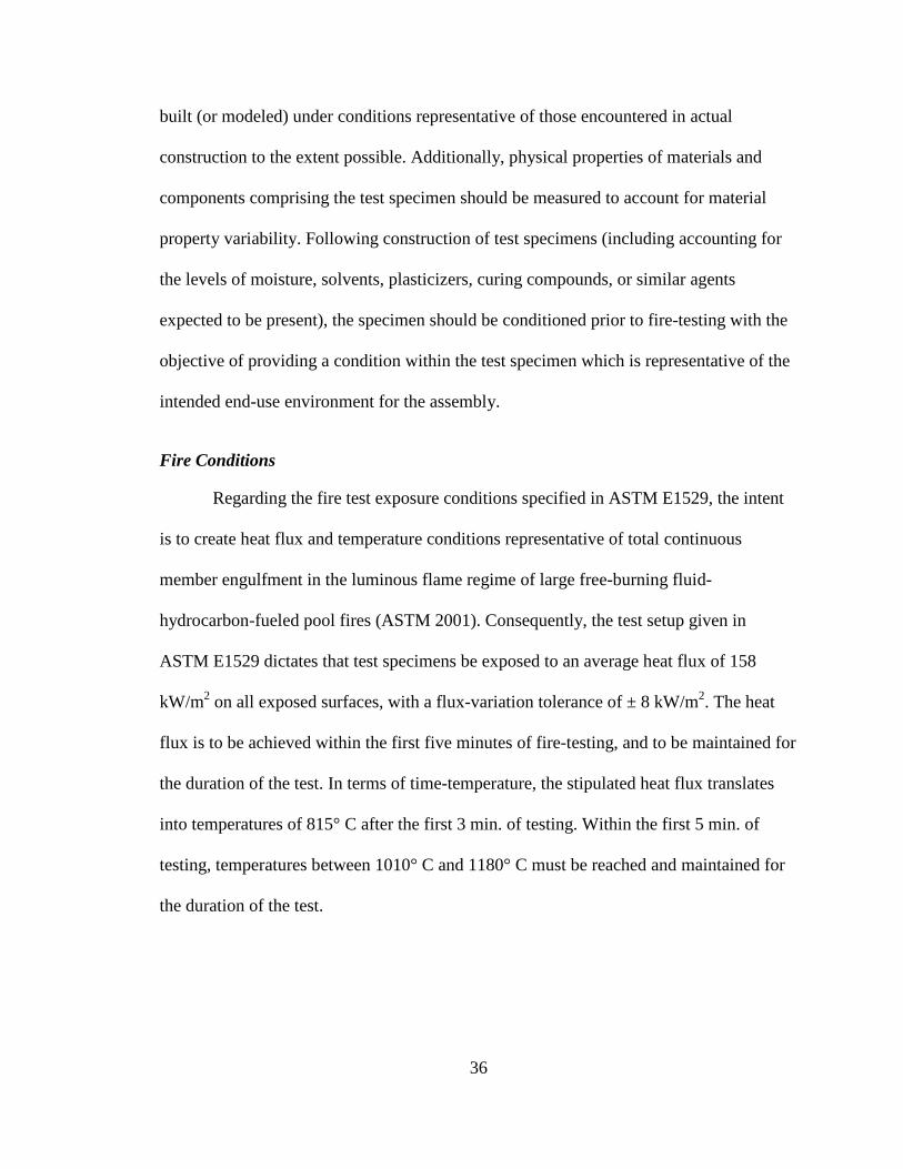
Regarding the fire test exposure conditions specified in ASTM E1529, the intent
is to create heat flux and temperature conditions representative of total continuous
member engulfment in the luminous flame regime of large free-burning fluid-
hydrocarbon-fueled pool fires (ASTM 2001). Consequently, the test setup given in
ASTM E1529 dictates that test specimens be exposed to an average heat flux of 158
kW/m2 on all exposed surfaces, with a flux-variation tolerance of ± 8 kW/m2. The heat
flux is to be achieved within the first five minutes of fire-testing, and to be maintained for
the duration of the test. In terms of time-temperature, the stipulated heat flux translates
into temperatures of 815° C after the first 3 min. of testing. Within the first 5 min. of
testing, temperatures between 1010° C and 1180° C must be reached and maintained for
the duration of the test.
37
Comparison of ASTM E1529 Fire Conditions to Forensic Findings
The average-valued time-temperature curve associated with ASTM E1529 is
shown in Fig. 22. For comparison, the estimated maximum temperatures reached during
the 2007 Oakland, California MacArthur Maze bridge fire, are also shown in Fig. 22
(details associated with this infamous bridge fire incident are given in Dunn and
Chowdhury 2009). The MacArthur Maze fire incident, which involved the ignition of a
fully-loaded gasoline tank truck, occurred directly beneath an interstate (structural steel
girder). Severe damage to multiple spans, and collapse of the overlying steel girder span
occurred as a result of the fire (Fig. 23). Forensic investigators estimated that the
maximum temperatures that developed in the structural members affected by the fire
were approximately 980° C (Dunn and Chowdhury 2009). Furthermore, the span directly
above the fire was estimated to collapse within approximately the first 20 min. of fire
ignition.
1000
500
0
1350
0 60 120
2000
1000
2460
Time (min.)
Tem
pera
ture
( C
)
Tem
pera
ture
( F
)
30 90
MacArthur MazeASTM E1529
Collapse at app. 20 min
Figure 22. ASTM E1529 time-temperature curve and estimated temperatures reached during the 2007 MacArthur Maze bridge fire in Oakland, California.
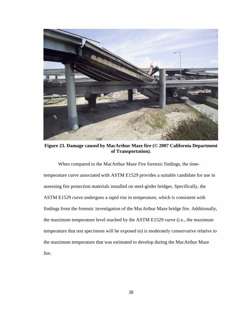
38
Figure 23. Damage caused by MacArthur Maze fire (© 2007 California Department
of Transportation).
When compared to the MacArthur Maze Fire forensic findings, the time-
temperature curve associated with ASTM E1529 provides a suitable candidate for use in
assessing fire protection materials installed on steel-girder bridges. Specifically, the
ASTM E1529 curve undergoes a rapid rise in temperature, which is consistent with
findings from the forensic investigation of the MacArthur Maze bridge fire. Additionally,
the maximum temperature level reached by the ASTM E1529 curve (i.e., the maximum
temperature that test specimens will be exposed to) is moderately conservative relative to
the maximum temperature that was estimated to develop during the MacArthur Maze
fire.
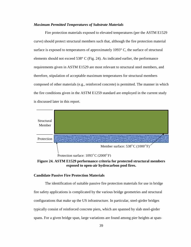
39
Maximum Permitted Temperatures of Substrate Materials
Fire protection materials exposed to elevated temperatures (per the ASTM E1529
curve) should protect structural members such that, although the fire protection material
surface is exposed to temperatures of approximately 1093° C, the surface of structural
elements should not exceed 538° C (Fig. 24). As indicated earlier, the performance
requirements given in ASTM E1529 are most relevant to structural steel members, and
therefore, stipulation of acceptable maximum temperatures for structural members
composed of other materials (e.g., reinforced concrete) is permitted. The manner in which
the fire conditions given in the ASTM E1259 standard are employed in the current study
is discussed later in this report.
Protection
Member surface: 538 C (1000 F)
StructuralMember
Protection surface: 1093 C (2000 F) Figure 24. ASTM E1529 performance criteria for protected structural members
exposed to open-air hydrocarbon pool fires.
Candidate Passive Fire Protection Materials
The identification of suitable passive fire protection materials for use in bridge
fire safety applications is complicated by the various bridge geometries and structural
configurations that make up the US infrastructure. In particular, steel-girder bridges
typically consist of reinforced concrete piers, which are spanned by slab steel-girder
spans. For a given bridge span, large variations are found among pier heights at span-
40
ends, superstructure span lengths, superstructure-to-substructure bearing assemblies, the
number of steel girders along the span, and the depth of each steel girder. Additionally,
for complex interstate or highway interchanges, separate bridge spans may fall directly
above or below a given steel-girder bridge span. As discussed above, such variability is
prohibitive with respect to the potential use of pre-cut, pre-rigidized fire protection
materials (e.g., pre-engineered cladding).
The necessity to maintain vertical clearances (so as to prevent commercial truck
collisions with overpass girder portions that are positioned above underpass roadways)
presents an additional challenge in the identification of suitable bridge fire protection
materials. Typically, bridge superstructure configurations are designed to minimally meet
or exceed required vertical clearances for economic purposes. Therefore, the use of fire
protection materials that require the addition of relatively thick material layers (i.e., those
greater than approximately 5.1 cm) is precluded.
Intumescent Coatings
Spray-applied intumescent coatings circumvent the need to prefabricate rigidized
panels for bridge members. Even thin applications of intumescent materials (of only a
few millimeters) can provide significant fire protection to coated members. While
material costs associated with intumescent coatings can be prohibitively expensive, a
relatively inexpensive, high-performance product has been identified as part of the
current study. Namely, the intumescent mastic coating Albi 800 (Albi 2012) has been
selected for study in assessing the associated material ability to passively protect steel-
girder bridges against severe fires. Thermal properties, and potential fire protection
41
benefits of this material, in relation to fire protection of steel-girder bridges, are discussed
in detail later in this report.
Refractory Cements
Spray-applied refractory cements, while requiring thicknesses on the order of 2.5
cm to 5 cm, constitute an additional candidate for use in passive fire protection of steel-
girder bridges. While only a small number of refractory cementitious products are
manufactured to withstand thermal loads associated with severe fires, one such product
has been identified for use in the current study. As discussed above, the FireBarrierTM
135 refractory cementitious product (Morgan-Thermal Ceramics 2004) has been shown
to insulate protected substrates from elevated temperatures, even when exposed to full-
scale fire testing, where temperatures reached 900° C. The thermal properties and
robustness of the FireBarrierTM 135 product are detailed later in this report.
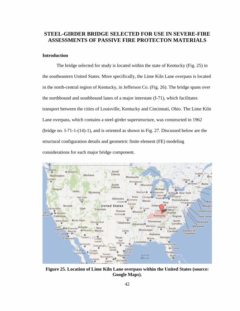
42
STEEL-GIRDER BRIDGE SELECTED FOR USE IN SEVERE-FIRE ASSESSMENTS OF PASSIVE FIRE PROTECTON MATERIALS
Introduction
The bridge selected for study is located within the state of Kentucky (Fig. 25) in
the southeastern United States. More specifically, the Lime Kiln Lane overpass is located
in the north-central region of Kentucky, in Jefferson Co. (Fig. 26). The bridge spans over
the northbound and southbound lanes of a major interstate (I-71), which facilitates
transport between the cities of Louisville, Kentucky and Cincinnati, Ohio. The Lime Kiln
Lane overpass, which contains a steel-girder superstructure, was constructed in 1962
(bridge no. I-71-1-(14)-1), and is oriented as shown in Fig. 27. Discussed below are the
structural configuration details and geometric finite element (FE) modeling
considerations for each major bridge component.
Figure 25. Location of Lime Kiln Lane overpass within the United States (source:
Google Maps).
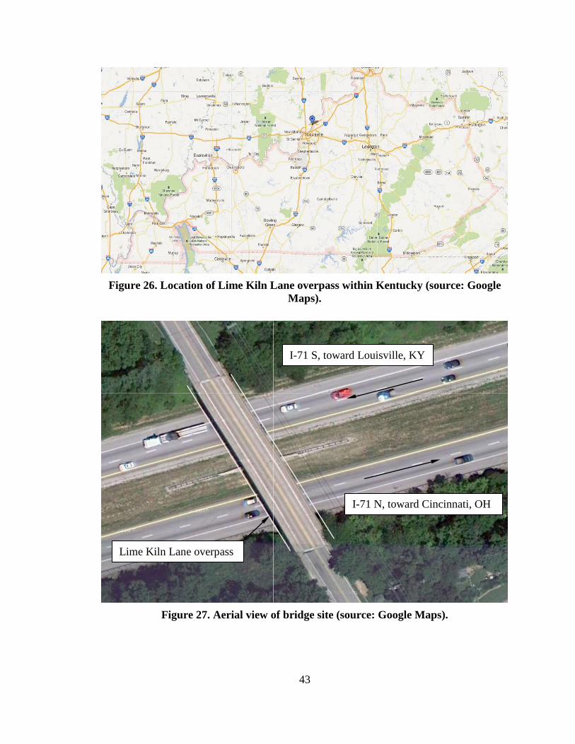
43
Figure 26. Location of Lime Kiln Lane overpass within Kentucky (source: Google
Maps).
Figure 27. Aerial view of bridge site (source: Google Maps).
Lime Kiln Lane overpass
I-71 N, toward Cincinnati, OH
I-71 S, toward Louisville, KY
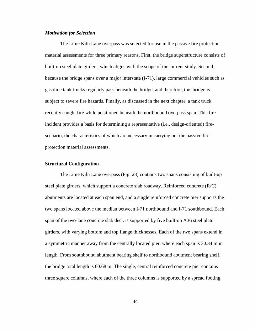
44
Motivation for Selection
The Lime Kiln Lane overpass was selected for use in the passive fire protection
material assessments for three primary reasons. First, the bridge superstructure consists of
built-up steel plate girders, which aligns with the scope of the current study. Second,
because the bridge spans over a major interstate (I-71), large commercial vehicles such as
gasoline tank trucks regularly pass beneath the bridge, and therefore, this bridge is
subject to severe fire hazards. Finally, as discussed in the next chapter, a tank truck
recently caught fire while positioned beneath the northbound overpass span. This fire
incident provides a basis for determining a representative (i.e., design-oriented) fire-
scenario, the characteristics of which are necessary in carrying out the passive fire
protection material assessments.
Structural Configuration
The Lime Kiln Lane overpass (Fig. 28) contains two spans consisting of built-up
steel plate girders, which support a concrete slab roadway. Reinforced concrete (R/C)
abutments are located at each span end, and a single reinforced concrete pier supports the
two spans located above the median between I-71 northbound and I-71 southbound. Each
span of the two-lane concrete slab deck is supported by five built-up A36 steel plate
girders, with varying bottom and top flange thicknesses. Each of the two spans extend in
a symmetric manner away from the centrally located pier, where each span is 30.34 m in
length. From southbound abutment bearing shelf to northbound abutment bearing shelf,
the bridge total length is 60.68 m. The single, central reinforced concrete pier contains
three square columns, where each of the three columns is supported by a spread footing.
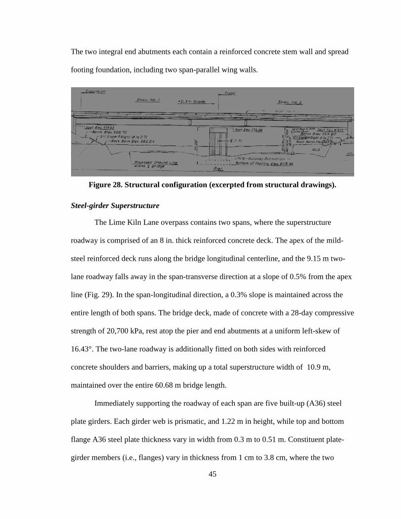
45
The two integral end abutments each contain a reinforced concrete stem wall and spread
footing foundation, including two span-parallel wing walls.
Figure 28. Structural configuration (excerpted from structural drawings).
Steel-girder Superstructure
The Lime Kiln Lane overpass contains two spans, where the superstructure
roadway is comprised of an 8 in. thick reinforced concrete deck. The apex of the mild-
steel reinforced deck runs along the bridge longitudinal centerline, and the 9.15 m two-
lane roadway falls away in the span-transverse direction at a slope of 0.5% from the apex
line (Fig. 29). In the span-longitudinal direction, a 0.3% slope is maintained across the
entire length of both spans. The bridge deck, made of concrete with a 28-day compressive
strength of 20,700 kPa, rest atop the pier and end abutments at a uniform left-skew of
16.43°. The two-lane roadway is additionally fitted on both sides with reinforced
concrete shoulders and barriers, making up a total superstructure width of 10.9 m,
maintained over the entire 60.68 m bridge length.
Immediately supporting the roadway of each span are five built-up (A36) steel
plate girders. Each girder web is prismatic, and 1.22 m in height, while top and bottom
flange A36 steel plate thickness vary in width from 0.3 m to 0.51 m. Constituent plate-
girder members (i.e., flanges) vary in thickness from 1 cm to 3.8 cm, where the two
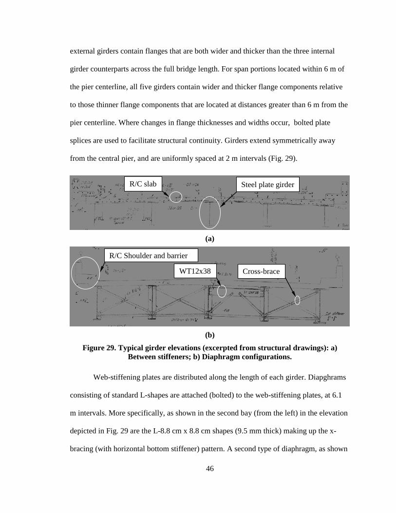
46
external girders contain flanges that are both wider and thicker than the three internal
girder counterparts across the full bridge length. For span portions located within 6 m of
the pier centerline, all five girders contain wider and thicker flange components relative
to those thinner flange components that are located at distances greater than 6 m from the
pier centerline. Where changes in flange thicknesses and widths occur, bolted plate
splices are used to facilitate structural continuity. Girders extend symmetrically away
from the central pier, and are uniformly spaced at 2 m intervals (Fig. 29).
(a)
(b)
Figure 29. Typical girder elevations (excerpted from structural drawings): a) Between stiffeners; b) Diaphragm configurations.
Web-stiffening plates are distributed along the length of each girder. Diapghrams
consisting of standard L-shapes are attached (bolted) to the web-stiffening plates, at 6.1
m intervals. More specifically, as shown in the second bay (from the left) in the elevation
depicted in Fig. 29 are the L-8.8 cm x 8.8 cm shapes (9.5 mm thick) making up the x-
bracing (with horizontal bottom stiffener) pattern. A second type of diaphragm, as shown
Steel plate girder R/C slab
R/C Shoulder and barrier
Cross-brace WT12x38
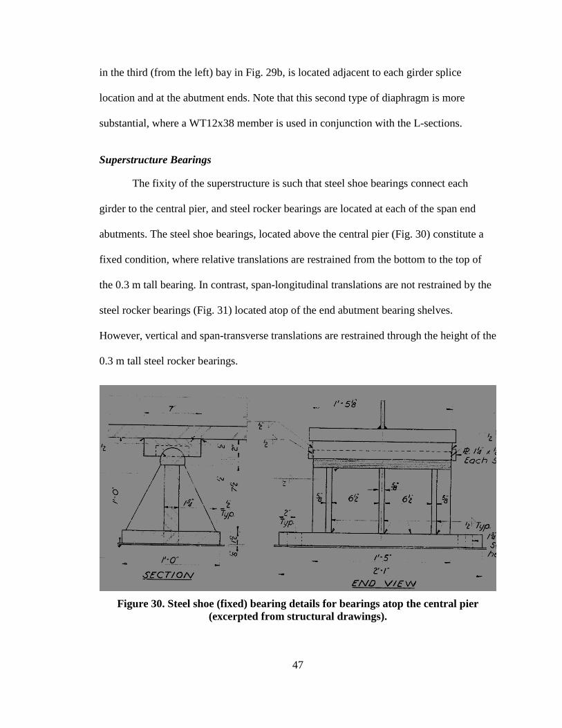
47
in the third (from the left) bay in Fig. 29b, is located adjacent to each girder splice
location and at the abutment ends. Note that this second type of diaphragm is more
substantial, where a WT12x38 member is used in conjunction with the L-sections.
Superstructure Bearings
The fixity of the superstructure is such that steel shoe bearings connect each
girder to the central pier, and steel rocker bearings are located at each of the span end
abutments. The steel shoe bearings, located above the central pier (Fig. 30) constitute a
fixed condition, where relative translations are restrained from the bottom to the top of
the 0.3 m tall bearing. In contrast, span-longitudinal translations are not restrained by the
steel rocker bearings (Fig. 31) located atop of the end abutment bearing shelves.
However, vertical and span-transverse translations are restrained through the height of the
0.3 m tall steel rocker bearings.
Figure 30. Steel shoe (fixed) bearing details for bearings atop the central pier
(excerpted from structural drawings).
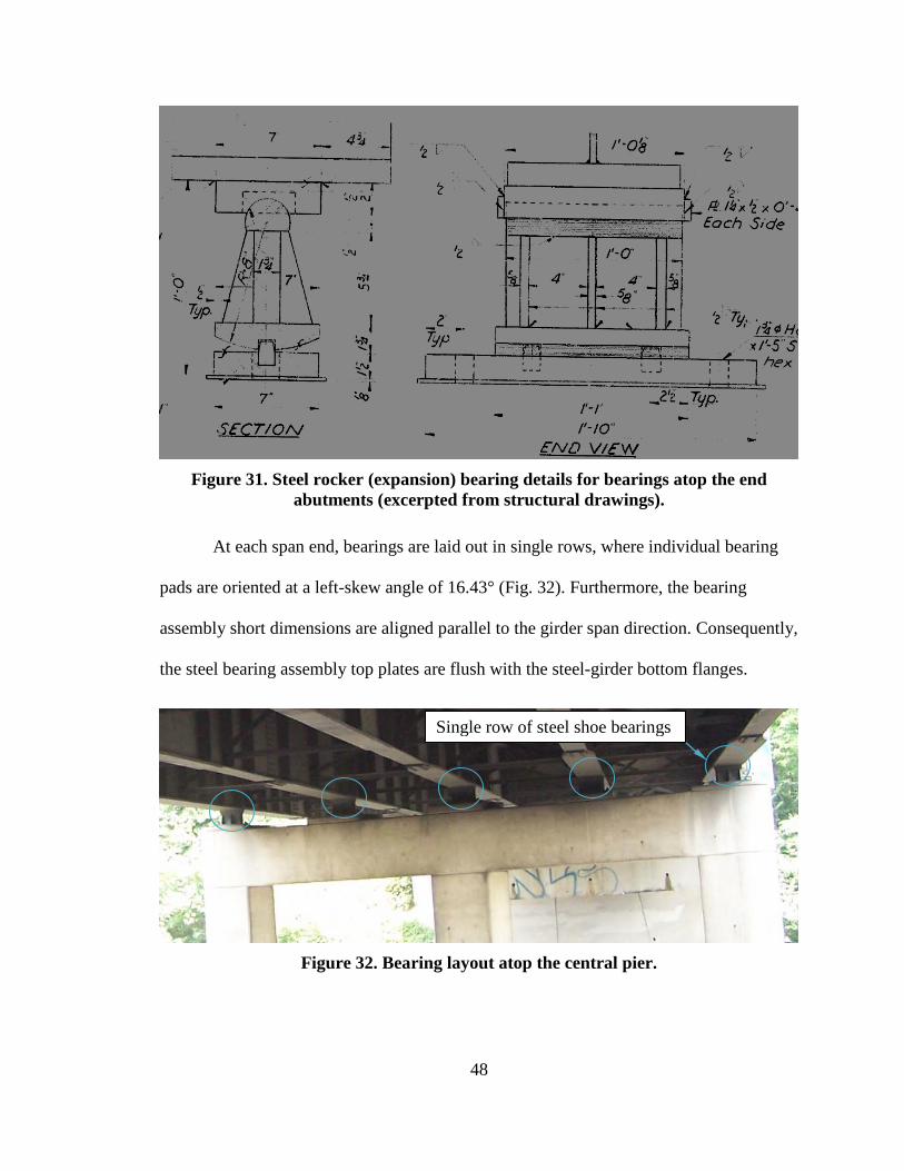
48
Figure 31. Steel rocker (expansion) bearing details for bearings atop the end
abutments (excerpted from structural drawings).
At each span end, bearings are laid out in single rows, where individual bearing
pads are oriented at a left-skew angle of 16.43° (Fig. 32). Furthermore, the bearing
assembly short dimensions are aligned parallel to the girder span direction. Consequently,
the steel bearing assembly top plates are flush with the steel-girder bottom flanges.
Figure 32. Bearing layout atop the central pier.
Single row of steel shoe bearings
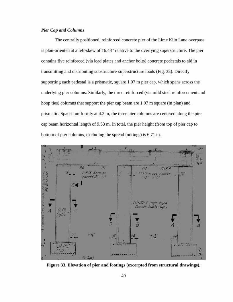
49
Pier Cap and Columns
The centrally positioned, reinforced concrete pier of the Lime Kiln Lane overpass
is plan-oriented at a left-skew of 16.43° relative to the overlying superstructure. The pier
contains five reinforced (via lead plates and anchor bolts) concrete pedestals to aid in
transmitting and distributing substructure-superstructure loads (Fig. 33). Directly
supporting each pedestal is a prismatic, square 1.07 m pier cap, which spans across the
underlying pier columns. Similarly, the three reinforced (via mild steel reinforcement and
hoop ties) columns that support the pier cap beam are 1.07 m square (in plan) and
prismatic. Spaced uniformly at 4.2 m, the three pier columns are centered along the pier
cap beam horizontal length of 9.53 m. In total, the pier height (from top of pier cap to
bottom of pier columns, excluding the spread footings) is 6.71 m.
Figure 33. Elevation of pier and footings (excerpted from structural drawings).
50
Pier Footings and Soil
Positioned beneath the single, central pier of the Lime Kiln Lane overpass are
three independent, shallow-foundation, reinforced-concrete spread footings of 20,700 kPa
twenty-eight day compressive strength (Fig. 33). Post-construction soil surface elevations
for the bridge (recall Fig. 28) are such that the spread footings (located beneath each pier
column) are fully embedded in soil, and rest directly on limestone bedrock. As denoted in
the structural drawings, core recovery percentages are 100% for the limestone that was
sampled in the immediate vicinity of the pier, indicating that the pier bearing surface is of
high quality.
All three footings, which are centered beneath the respective pier columns, are
oriented consistently with the overlying piers. Specifically, the left-skew of 16.43°
(relative to the superstructure longitudinal direction) is maintained in the footing
orientations. In plan, each footing is square with 1.98 m by 1.98 m dimensions.
Additionally, the footings are 0.91 m thick, with concentrations of mild steel
reinforcement near the top and bottom footing faces.
Abutments
The end abutment located at the east end (nearest to I-71 northbound), and
symmetric with the west end abutment, is shown in plan view in Fig. 34. Relative to the
central pier, the abutment contains high stiffness, where the abutment is supported by a
wall stem, wing walls (denoted “Wing A” and “Wing B” in Fig. 34). Additionally, the
abutment is supported beneath the entirety of the wall stem and the majority of the wing
walls by a continuous, c-shaped, reinforced concrete spread footing.
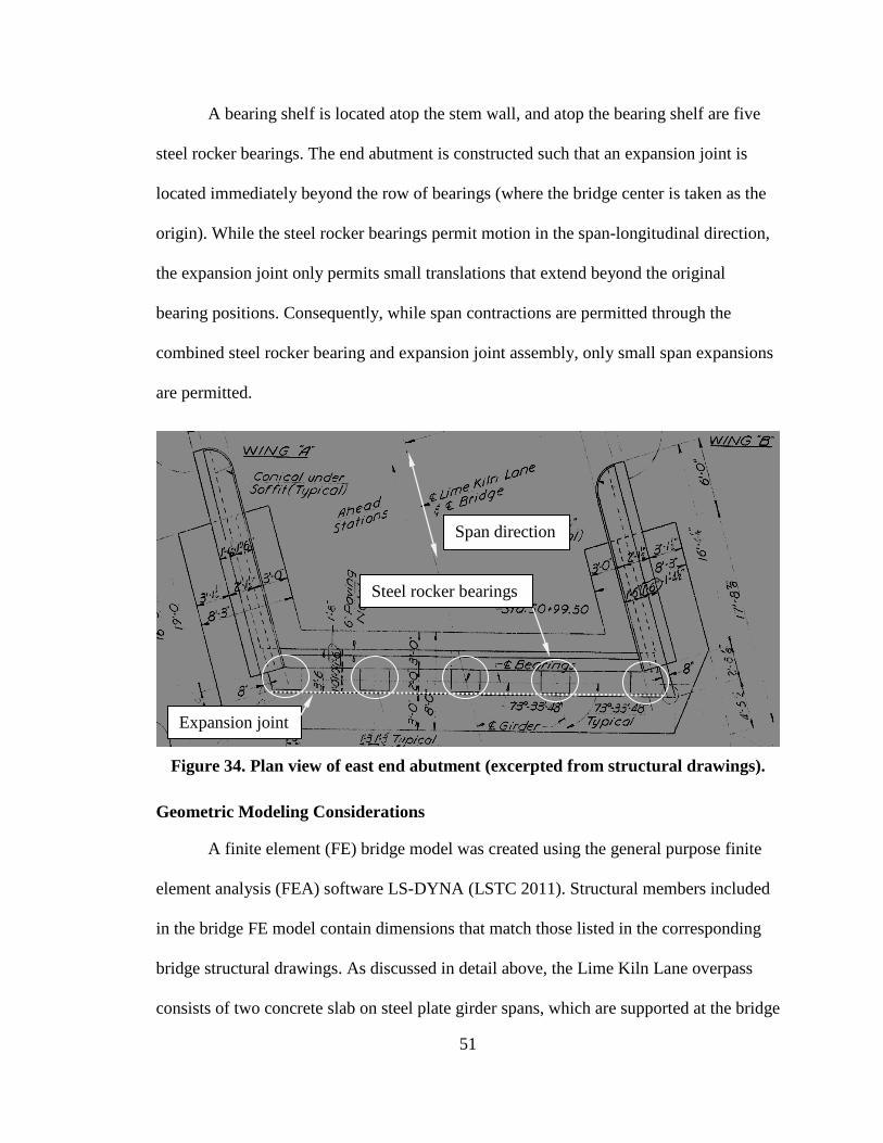
51
A bearing shelf is located atop the stem wall, and atop the bearing shelf are five
steel rocker bearings. The end abutment is constructed such that an expansion joint is
located immediately beyond the row of bearings (where the bridge center is taken as the
origin). While the steel rocker bearings permit motion in the span-longitudinal direction,
the expansion joint only permits small translations that extend beyond the original
bearing positions. Consequently, while span contractions are permitted through the
combined steel rocker bearing and expansion joint assembly, only small span expansions
are permitted.
Figure 34. Plan view of east end abutment (excerpted from structural drawings).
Geometric Modeling Considerations
A finite element (FE) bridge model was created using the general purpose finite
element analysis (FEA) software LS-DYNA (LSTC 2011). Structural members included
in the bridge FE model contain dimensions that match those listed in the corresponding
bridge structural drawings. As discussed in detail above, the Lime Kiln Lane overpass
consists of two concrete slab on steel plate girder spans, which are supported at the bridge
Steel rocker bearings
Expansion joint
Span direction
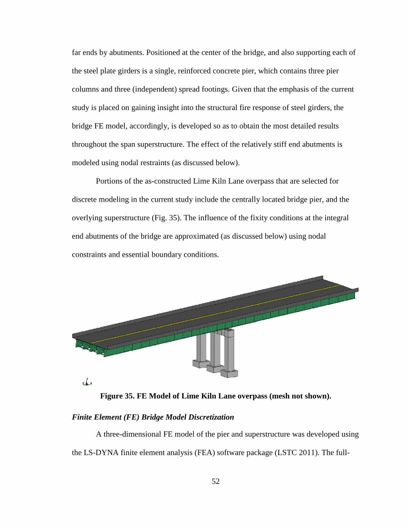
52
far ends by abutments. Positioned at the center of the bridge, and also supporting each of
the steel plate girders is a single, reinforced concrete pier, which contains three pier
columns and three (independent) spread footings. Given that the emphasis of the current
study is placed on gaining insight into the structural fire response of steel girders, the
bridge FE model, accordingly, is developed so as to obtain the most detailed results
throughout the span superstructure. The effect of the relatively stiff end abutments is
modeled using nodal restraints (as discussed below).
Portions of the as-constructed Lime Kiln Lane overpass that are selected for
discrete modeling in the current study include the centrally located bridge pier, and the
overlying superstructure (Fig. 35). The influence of the fixity conditions at the integral
end abutments of the bridge are approximated (as discussed below) using nodal
constraints and essential boundary conditions.
Figure 35. FE Model of Lime Kiln Lane overpass (mesh not shown).
Finite Element (FE) Bridge Model Discretization
A three-dimensional FE model of the pier and superstructure was developed using
the LS-DYNA finite element analysis (FEA) software package (LSTC 2011). The full-
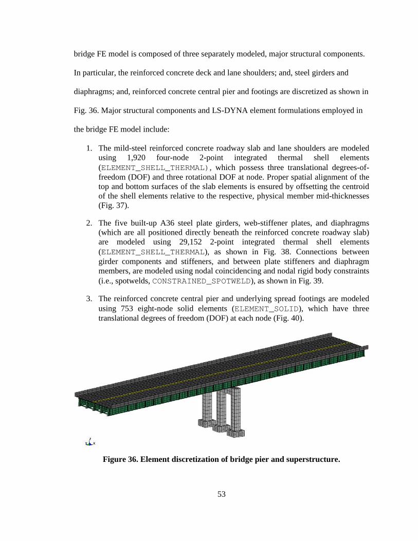
53
bridge FE model is composed of three separately modeled, major structural components.
In particular, the reinforced concrete deck and lane shoulders; and, steel girders and
diaphragms; and, reinforced concrete central pier and footings are discretized as shown in
Fig. 36. Major structural components and LS-DYNA element formulations employed in
the bridge FE model include:
1. The mild-steel reinforced concrete roadway slab and lane shoulders are modeled using 1,920 four-node 2-point integrated thermal shell elements (ELEMENT_SHELL_THERMAL), which possess three translational degrees-of-freedom (DOF) and three rotational DOF at node. Proper spatial alignment of the top and bottom surfaces of the slab elements is ensured by offsetting the centroid of the shell elements relative to the respective, physical member mid-thicknesses (Fig. 37).
2. The five built-up A36 steel plate girders, web-stiffener plates, and diaphragms (which are all positioned directly beneath the reinforced concrete roadway slab) are modeled using 29,152 2-point integrated thermal shell elements (ELEMENT_SHELL_THERMAL), as shown in Fig. 38. Connections between girder components and stiffeners, and between plate stiffeners and diaphragm members, are modeled using nodal coincidencing and nodal rigid body constraints (i.e., spotwelds, CONSTRAINED_SPOTWELD), as shown in Fig. 39.
3. The reinforced concrete central pier and underlying spread footings are modeled using 753 eight-node solid elements (ELEMENT_SOLID), which have three translational degrees of freedom (DOF) at each node (Fig. 40).
Figure 36. Element discretization of bridge pier and superstructure.
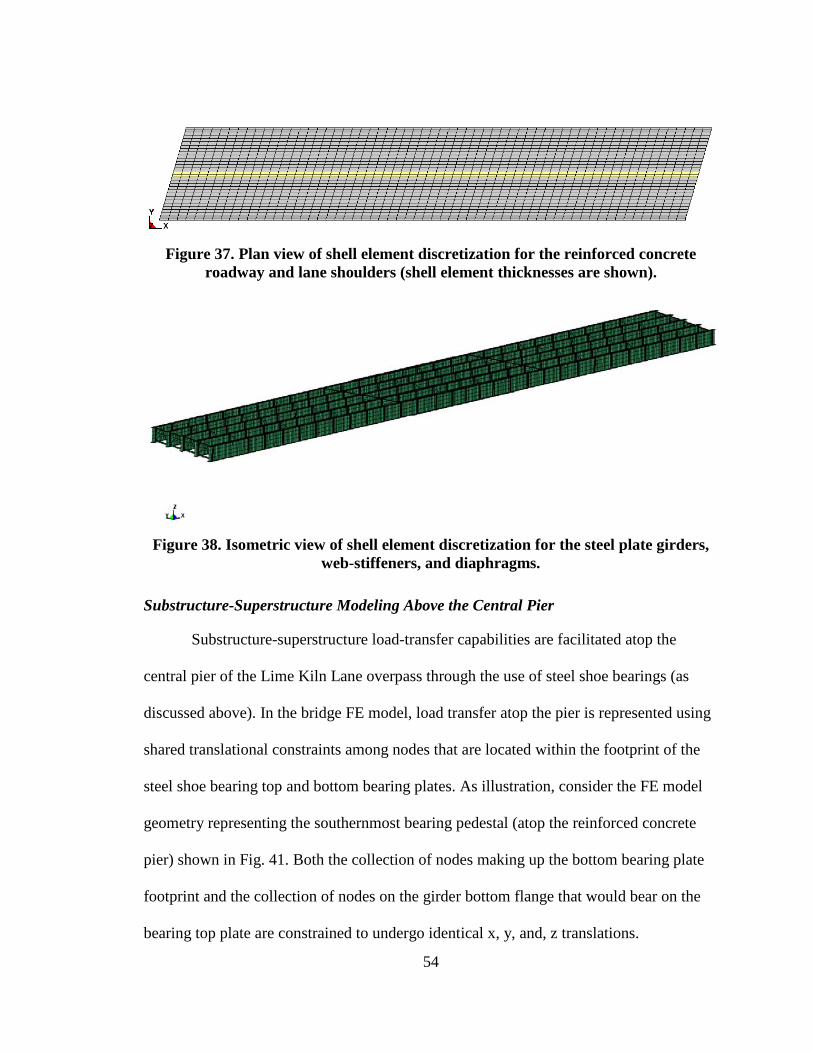
54
Figure 37. Plan view of shell element discretization for the reinforced concrete
roadway and lane shoulders (shell element thicknesses are shown).
Figure 38. Isometric view of shell element discretization for the steel plate girders,
web-stiffeners, and diaphragms.
Substructure-Superstructure Modeling Above the Central Pier
Substructure-superstructure load-transfer capabilities are facilitated atop the
central pier of the Lime Kiln Lane overpass through the use of steel shoe bearings (as
discussed above). In the bridge FE model, load transfer atop the pier is represented using
shared translational constraints among nodes that are located within the footprint of the
steel shoe bearing top and bottom bearing plates. As illustration, consider the FE model
geometry representing the southernmost bearing pedestal (atop the reinforced concrete
pier) shown in Fig. 41. Both the collection of nodes making up the bottom bearing plate
footprint and the collection of nodes on the girder bottom flange that would bear on the
bearing top plate are constrained to undergo identical x, y, and, z translations.
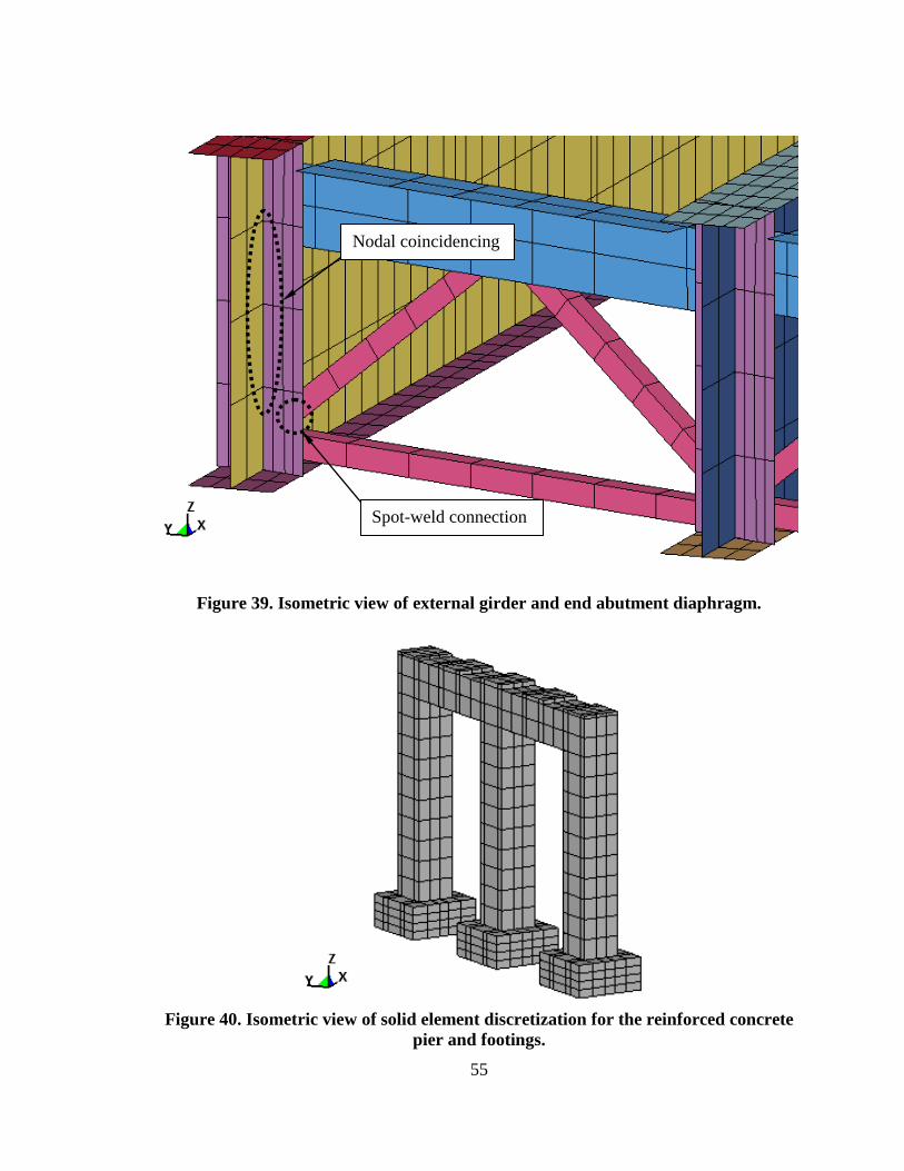
55
Figure 39. Isometric view of external girder and end abutment diaphragm.
Figure 40. Isometric view of solid element discretization for the reinforced concrete
pier and footings.
Spot-weld connection
Nodal coincidencing
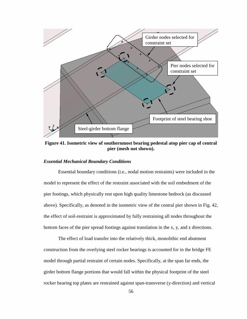
56
Figure 41. Isometric view of southernmost bearing pedestal atop pier cap of central
pier (mesh not shown).
Essential Mechanical Boundary Conditions
Essential boundary conditions (i.e., nodal motion restraints) were included in the
model to represent the effect of the restraint associated with the soil embedment of the
pier footings, which physically rest upon high quality limestone bedrock (as discussed
above). Specifically, as denoted in the isometric view of the central pier shown in Fig. 42,
the effect of soil-restraint is approximated by fully restraining all nodes throughout the
bottom faces of the pier spread footings against translation in the x, y, and z directions.
The effect of load transfer into the relatively thick, monolithic end abutment
construction from the overlying steel rocker bearings is accounted for in the bridge FE
model through partial restraint of certain nodes. Specifically, at the span far ends, the
girder bottom flange portions that would fall within the physical footprint of the steel
rocker bearing top plates are restrained against span-transverse (y-direction) and vertical
Footprint of steel bearing shoe
Steel-girder bottom flange
Girder nodes selected for constraint set
Pier nodes selected for constraint set

57
(z-direction) translation (Fig. 43). Additionally, the highlighted nodes are permitted to
undergo motion in the x-direction that would be associated with contraction of the girders
(i.e., negative x-direction motion). Positive motion in the x-direction, however, is not
permitted, where this partial restraint is consistent with the on-site (physical) presence of
an expansion joint on the far side of the steel rocker bearings and span far ends.
Figure 42. Isometric view from beneath the central pier (mesh not shown).
Nodes fully restrained against translation
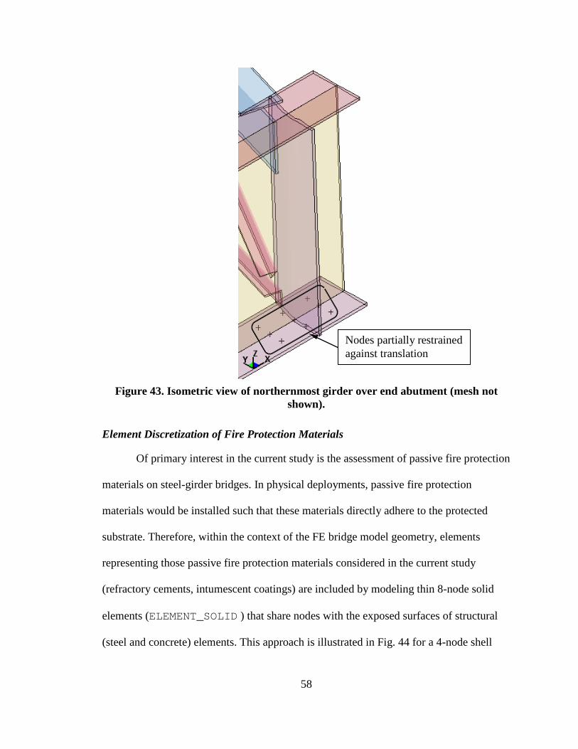
58
Figure 43. Isometric view of northernmost girder over end abutment (mesh not
shown).
Element Discretization of Fire Protection Materials
Of primary interest in the current study is the assessment of passive fire protection
materials on steel-girder bridges. In physical deployments, passive fire protection
materials would be installed such that these materials directly adhere to the protected
substrate. Therefore, within the context of the FE bridge model geometry, elements
representing those passive fire protection materials considered in the current study
(refractory cements, intumescent coatings) are included by modeling thin 8-node solid
elements (ELEMENT_SOLID ) that share nodes with the exposed surfaces of structural
(steel and concrete) elements. This approach is illustrated in Fig. 44 for a 4-node shell
Nodes partially restrained against translation
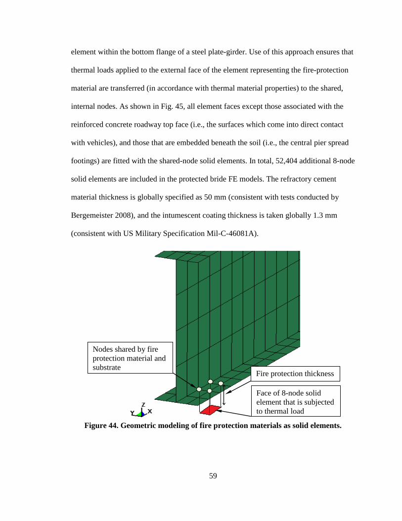
59
element within the bottom flange of a steel plate-girder. Use of this approach ensures that
thermal loads applied to the external face of the element representing the fire-protection
material are transferred (in accordance with thermal material properties) to the shared,
internal nodes. As shown in Fig. 45, all element faces except those associated with the
reinforced concrete roadway top face (i.e., the surfaces which come into direct contact
with vehicles), and those that are embedded beneath the soil (i.e., the central pier spread
footings) are fitted with the shared-node solid elements. In total, 52,404 additional 8-node
solid elements are included in the protected bride FE models. The refractory cement
material thickness is globally specified as 50 mm (consistent with tests conducted by
Bergemeister 2008), and the intumescent coating thickness is taken globally 1.3 mm
(consistent with US Military Specification Mil-C-46081A).
Figure 44. Geometric modeling of fire protection materials as solid elements.
Nodes shared by fire protection material and substrate
Fire protection thickness
Face of 8-node solid element that is subjected to thermal load
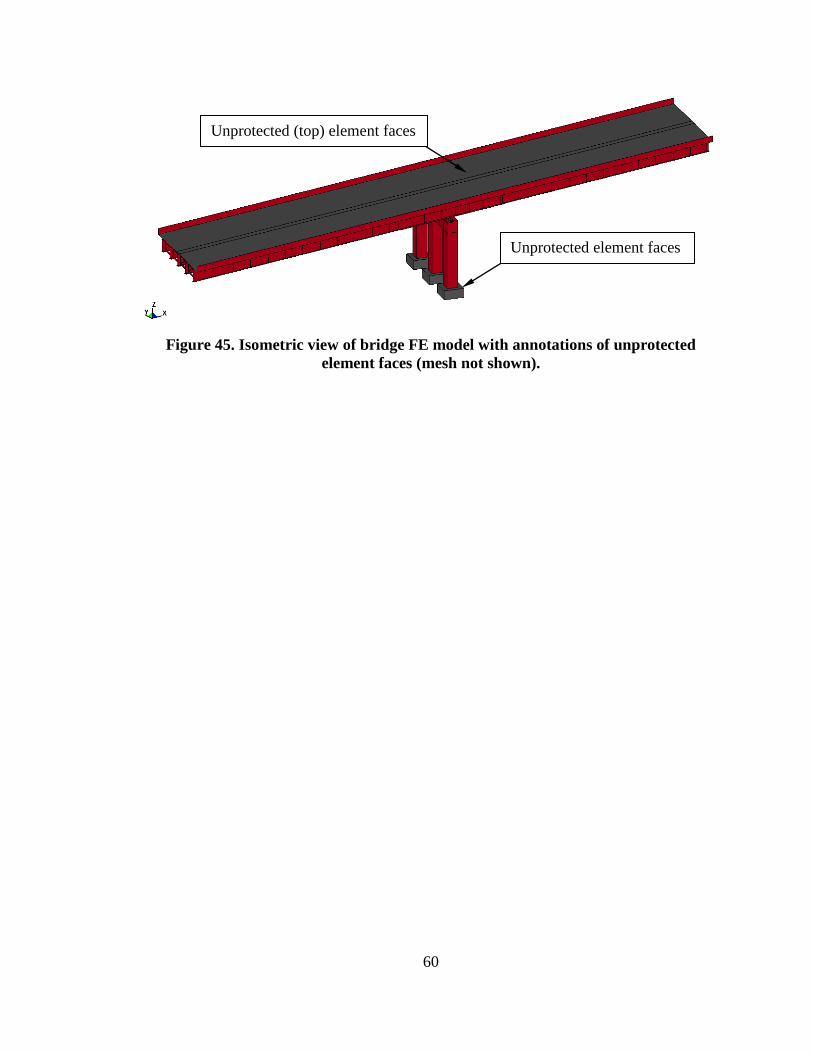
60
Figure 45. Isometric view of bridge FE model with annotations of unprotected
element faces (mesh not shown).
Unprotected (top) element faces
Unprotected element faces
61
CONSTITUTIVE AND THERMAL MODELING
Constitutive Modeling
In order to conduct coupled thermal-mechanical finite element analyses (FEA)
using the above-described bridge FE model geometry, both mechanical and thermal
properties must be specified for each of the reinforced concrete, A36 structural steel,
refractory cement, and intumescent coating materials. The general purpose FEA software
LS-DYNA (LSTC 2011) is employed in the current study, where (by default) LS-DYNA
employs large kinematics and (explicit) transient dynamic analysis. Both of these features
are necessary in making reasonable assessments of bridge fire-response.
In the following, the material models selected from the LS-DYNA material model
library are identified (LSTC 2012). Input parameters necessary to define the selected
material models are additionally justified and described. Given that material temperatures
of members exposed to open-air burning of a loaded gasoline tank truck are capable of
reaching 1093° C in 5 min. (ASTM 2001), material properties (as discussed below) are
generally sought over the temperature ranges of room temperature (20° C) up to 1100° C.
Also, it should be noted that the LS-DYNA software package requires that both structural
and thermal material definitions be included as part of the coupled thermal-mechanical
analyses (LSTC 2012).
Reinforced Concrete Material Models for Shell Elements
The LS-DYNA structural material model selected for use in modeling the
reinforced concrete roadway, lane shoulders, and barriers is MAT_CONCRETE_EC2. This
structural material model is recommended in LSTC (2012) for modeling mild-steel
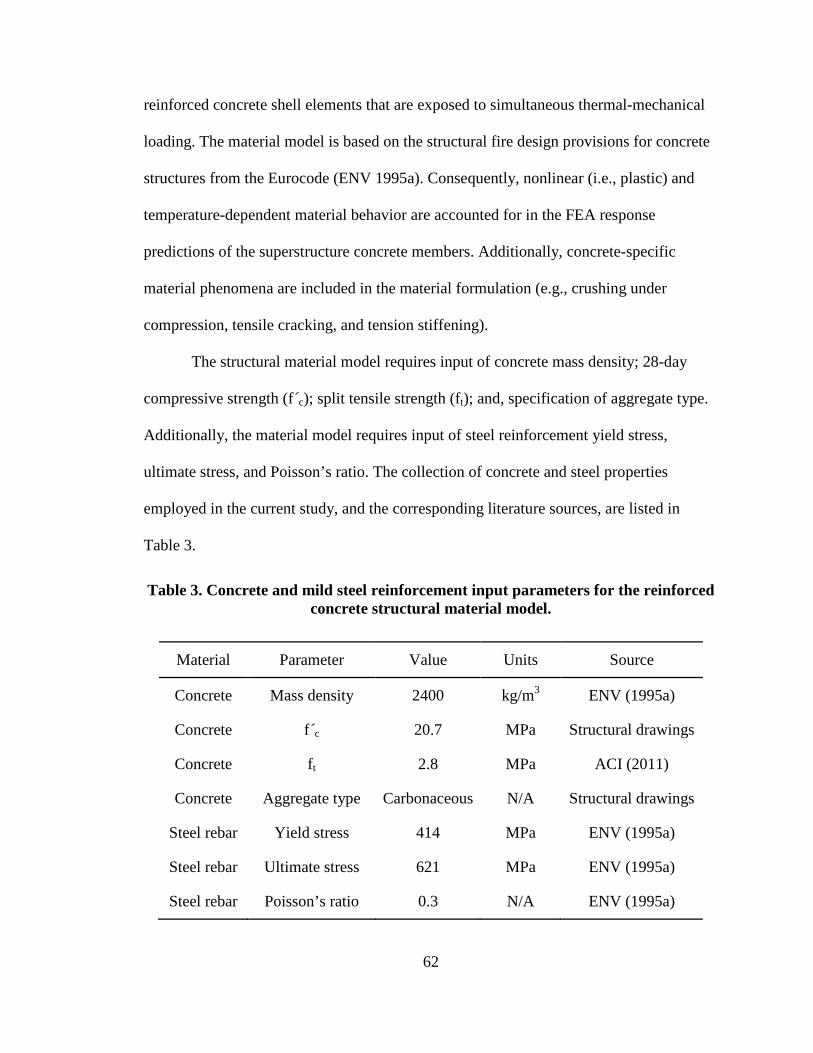
62
reinforced concrete shell elements that are exposed to simultaneous thermal-mechanical
loading. The material model is based on the structural fire design provisions for concrete
structures from the Eurocode (ENV 1995a). Consequently, nonlinear (i.e., plastic) and
temperature-dependent material behavior are accounted for in the FEA response
predictions of the superstructure concrete members. Additionally, concrete-specific
material phenomena are included in the material formulation (e.g., crushing under
compression, tensile cracking, and tension stiffening).
The structural material model requires input of concrete mass density; 28-day
compressive strength (f´c); split tensile strength (ft); and, specification of aggregate type.
Additionally, the material model requires input of steel reinforcement yield stress,
ultimate stress, and Poisson’s ratio. The collection of concrete and steel properties
employed in the current study, and the corresponding literature sources, are listed in
Table 3.
Table 3. Concrete and mild steel reinforcement input parameters for the reinforced concrete structural material model.
Material Parameter Value Units Source
Concrete Mass density 2400 kg/m3 ENV (1995a)
Concrete f´c 20.7 MPa Structural drawings
Concrete ft 2.8 MPa ACI (2011)
Concrete Aggregate type Carbonaceous N/A Structural drawings
Steel rebar Yield stress 414 MPa ENV (1995a)
Steel rebar Ultimate stress 621 MPa ENV (1995a)
Steel rebar Poisson’s ratio 0.3 N/A ENV (1995a)
63
Based on the properties listed in Table 3 and the fire-resistance provisions given
in the Eurocode (ENV 1995a), the MAT_CONCRETE_EC2 material model automatically
generates temperature-sensitive stress-strain curves and coefficients of thermal expansion
(LSTC 2012), over an arbitrary range of temperatures. It should be noted that the stress-
strain curves automatically generated as part of the material formulation take into account
the presence of the mild steel reinforcement. Namely, volumetric reinforcement ratios are
specified for the local x-direction and local y-direction, and based on these ratios,
smeared crack properties are calculated for each direction. For the reinforced concrete
roadway slab, lane shoulders, and barriers, x-direction (longitudinal) and y-direction
(transverse) reinforcement ratios are taken as 0.3% to 0.7%, respectively, consistent with
reinforcement layouts given in the structural drawings.
The LS-DYNA (LSTC 2012) thermal material model selected for use in modeling
the concrete superstructure members is MAT_THERMAL_ISOTROPIC_TD, which
requires input of thermal conductivities and specific heats over an arbitrary range of
temperatures. Values of thermal conductivity and specific heat given in the Eurocode
provisions (ENV 1995a) are supplied to the LS-DYNA material model in mixed 100° C
and 200° C increments (over the range of 0° C to 800° C). For higher temperature values,
linear extrapolations of the available highest-temperature data are employed to estimate
the corresponding values of thermal conductivity and specific heat capacity. Plots of the
thermal conductivity and specific heats are shown in Fig. 46 and Fig. 47, respectively.
Note that the ordinate axis bounds used in Fig. 46 and Fig. 47 are so selected to facilitate
comparisons between concrete and steel thermal properties (as shown for thermal
conductivity and specific heat in Fig. 50 and Fig. 51, respectively).
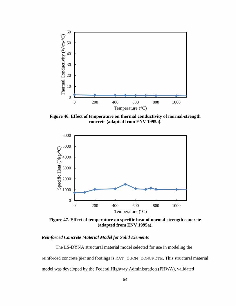
64
0
10
20
30
40
50
60
0 200 400 600 800 1000
Ther
mal
Con
duct
ivity
(W/m
-°C
)
Temperature (°C) Figure 46. Effect of temperature on thermal conductivity of normal-strength
concrete (adapted from ENV 1995a).
0
1000
2000
3000
4000
5000
6000
0 200 400 600 800 1000
Spec
ific
Hea
t (J/
kg-°
C)
Temperature (°C) Figure 47. Effect of temperature on specific heat of normal-strength concrete
(adapted from ENV 1995a).
Reinforced Concrete Material Model for Solid Elements
The LS-DYNA structural material model selected for use in modeling the
reinforced concrete pier and footings is MAT_CSCM_CONCRETE. This structural material
model was developed by the Federal Highway Administration (FHWA), validated
65
extensively, and shown to be capable of accurately predicting dynamic-load induced
elastoplastic damage, while accounting for kinematic hardening and strain-rate effects
(FHWA 2007). This structural material model does not directly incorporate temperature-
dependent stress and strain predictions. However, as discussed in detail later, the pier and
footing concrete are not directly exposed to extreme temperatures for the fire scenarios
considered, and therefore, no substantial pier-concrete degradations are expected. The
structural material model requires only the supplication of the 28-day unconfined
compressive strength to generate a stress-cap model. As indicated in the bridge structural
drawings, the concrete compressive strength is 20.7 MPa.
As required by the LS-DYNA software package (LSTC 2011), a thermal material
model is also specified for the 8-node solid elements that make up the pier and spread
footings. Accordingly, the MAT_THERMAL_ISOTROPIC_TD thermal material is
employed, consistent with the modeling approach taken to represent the reinforced
concrete superstructure thermal-shell elements. The input parameters associated with use
of this thermal material model (temperature-dependent values of thermal conductivity
and specific heat) were discussed previously (recall Fig. 46 and Fig. 47).
A36 Structural Steel
The LS-DYNA structural material model selected for use in modeling the steel
plate girders, web stiffeners, and diaphragm members is
MAT_ELASTIC_PLASTIC_THERMAL, which is recommended in LSTC (2012) for
modeling metallic elements that are subject to simultaneous thermal-mechanical loading.
By employing this material model, nonlinear (i.e., plastic) and temperature-dependent
material behavior are accounted for in the FEA response predictions of steel members.
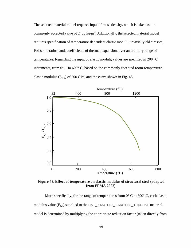
66
The selected material model requires input of mass density, which is taken as the
commonly accepted value of 2400 kg/m3. Additionally, the selected material model
requires specification of temperature-dependent elastic moduli; uniaxial yield stresses;
Poisson’s ratios; and, coefficients of thermal expansion, over an arbitrary range of
temperatures. Regarding the input of elastic moduli, values are specified in 200° C
increments, from 0° C to 600° C, based on the commonly accepted room-temperature
elastic modulus (Εs, o) of 200 GPa, and the curve shown in Fig. 48.
400 800
32 400
0.8
0.6
0.4
0.2
1.0
0.00
Temperature ( C)200 600
Temperature ( F)800 1200
Ε s, i
/ Εs,
o
Figure 48. Effect of temperature on elastic modulus of structural steel (adapted
from FEMA 2002).
More specifically, for the range of temperatures from 0° C to 600° C, each elastic
modulus value (Εs, i) supplied to the MAT_ELASTIC_PLASTIC_THERMAL material
model is determined by multiplying the appropriate reduction factor (taken directly from
67
Fig. 48) by the room-temperature elastic modulus (Εs, o). For temperatures between 600°
C and 1100° C, the corresponding elastic moduli are estimated based on Eurocode fire
resistance design provisions for steel structures (ENV 1995b). Effectively, magnitudes of
elastic moduli for steel at temperatures greater than 700° C are much less than 10% of the
corresponding Εs, o magnitude.
Temperature-dependent A36 structural steel yield stress values are also specified
in 200° C increments, from 0° C to 1000° C (as well as at 1100° C), based on the
commonly accepted room-temperature yield stress (σy, o) of 248 MPa and the curve
shown in Fig. 49. For the range of temperatures from 0° C to 600° C, each yield stress
value (σy, i) supplied to the MAT_ELASTIC_PLASTIC_THERMAL material model is
determined by multiplying the appropriate reduction factor (taken directly from Fig. 49)
by the room-temperature yield stress (σy, o). For temperatures between 600° C and 1100°
C, the corresponding elastic moduli are estimated based on interpolation of the curve
given in Fig. 49.
For a given temperature level, stress-strain curves are generated per the
MAT_ELASTIC_PLASTIC_THERMAL material model by pairing temperature-
dependent elastic moduli and yield stresses. The effect of strain hardening is additionally
accounted for in the material model through specification of tangent moduli at each
temperature level. Accordingly, temperature-dependent structural steel post-yield tangent
modulus values are estimated over the temperature range of 0° C to 600° C based on data
given in FEMA (2002). At higher temperature levels, the stress-strain data indicate
diminished propensities for strain-hardening in the steel material. Therefore, in the
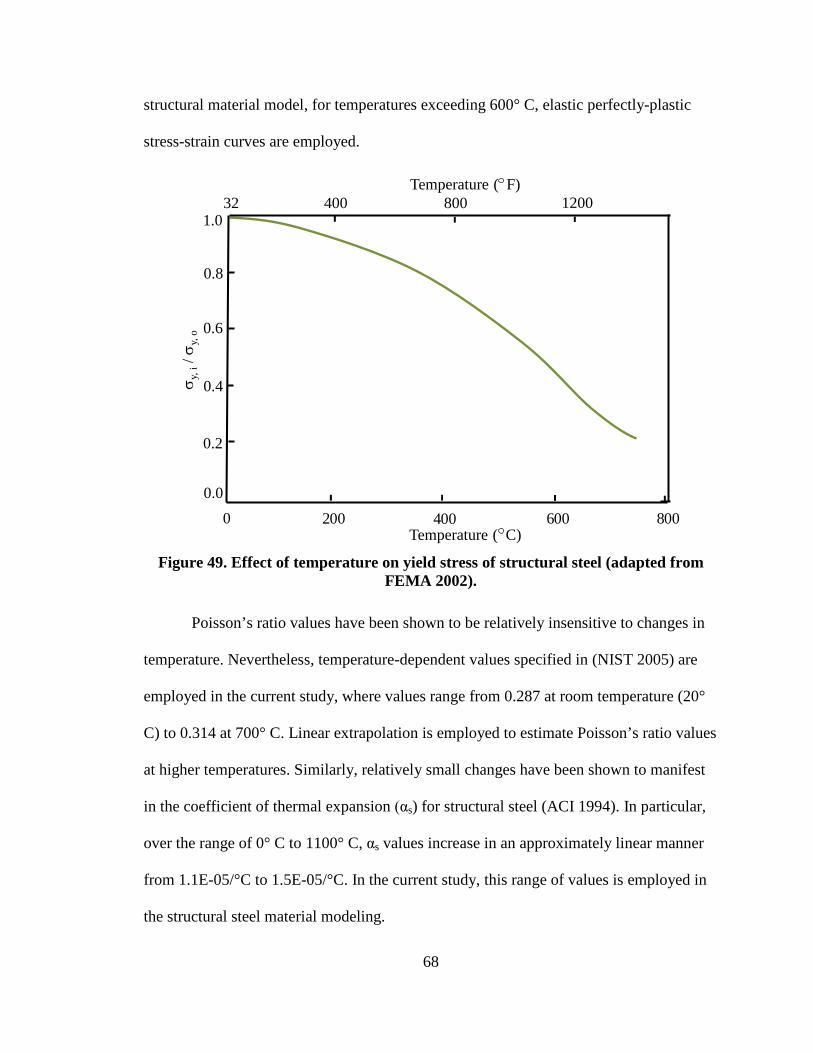
68
structural material model, for temperatures exceeding 600° C, elastic perfectly-plastic
stress-strain curves are employed.
σ y, i
/ σy,
o
400 800
32 400
0.8
0.6
0.4
0.2
1.0
0.00
Temperature ( C)200 600
Temperature ( F)800 1200
Figure 49. Effect of temperature on yield stress of structural steel (adapted from
FEMA 2002).
Poisson’s ratio values have been shown to be relatively insensitive to changes in
temperature. Nevertheless, temperature-dependent values specified in (NIST 2005) are
employed in the current study, where values range from 0.287 at room temperature (20°
C) to 0.314 at 700° C. Linear extrapolation is employed to estimate Poisson’s ratio values
at higher temperatures. Similarly, relatively small changes have been shown to manifest
in the coefficient of thermal expansion (αs) for structural steel (ACI 1994). In particular,
over the range of 0° C to 1100° C, αs values increase in an approximately linear manner
from 1.1E-05/°C to 1.5E-05/°C. In the current study, this range of values is employed in
the structural steel material modeling.
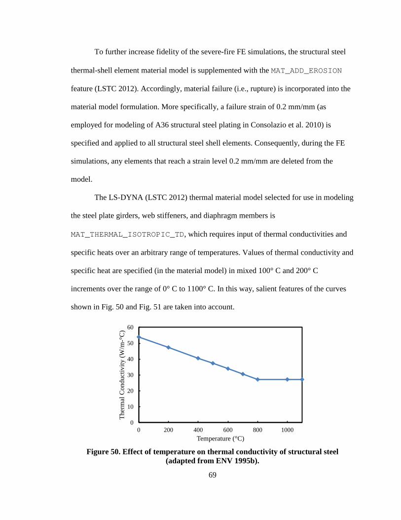
69
To further increase fidelity of the severe-fire FE simulations, the structural steel
thermal-shell element material model is supplemented with the MAT_ADD_EROSION
feature (LSTC 2012). Accordingly, material failure (i.e., rupture) is incorporated into the
material model formulation. More specifically, a failure strain of 0.2 mm/mm (as
employed for modeling of A36 structural steel plating in Consolazio et al. 2010) is
specified and applied to all structural steel shell elements. Consequently, during the FE
simulations, any elements that reach a strain level 0.2 mm/mm are deleted from the
model.
The LS-DYNA (LSTC 2012) thermal material model selected for use in modeling
the steel plate girders, web stiffeners, and diaphragm members is
MAT_THERMAL_ISOTROPIC_TD, which requires input of thermal conductivities and
specific heats over an arbitrary range of temperatures. Values of thermal conductivity and
specific heat are specified (in the material model) in mixed 100° C and 200° C
increments over the range of 0° C to 1100° C. In this way, salient features of the curves
shown in Fig. 50 and Fig. 51 are taken into account.
0
10
20
30
40
50
60
0 200 400 600 800 1000
Ther
mal
Con
duct
ivity
(W/m
-°C
)
Temperature (°C) Figure 50. Effect of temperature on thermal conductivity of structural steel
(adapted from ENV 1995b).
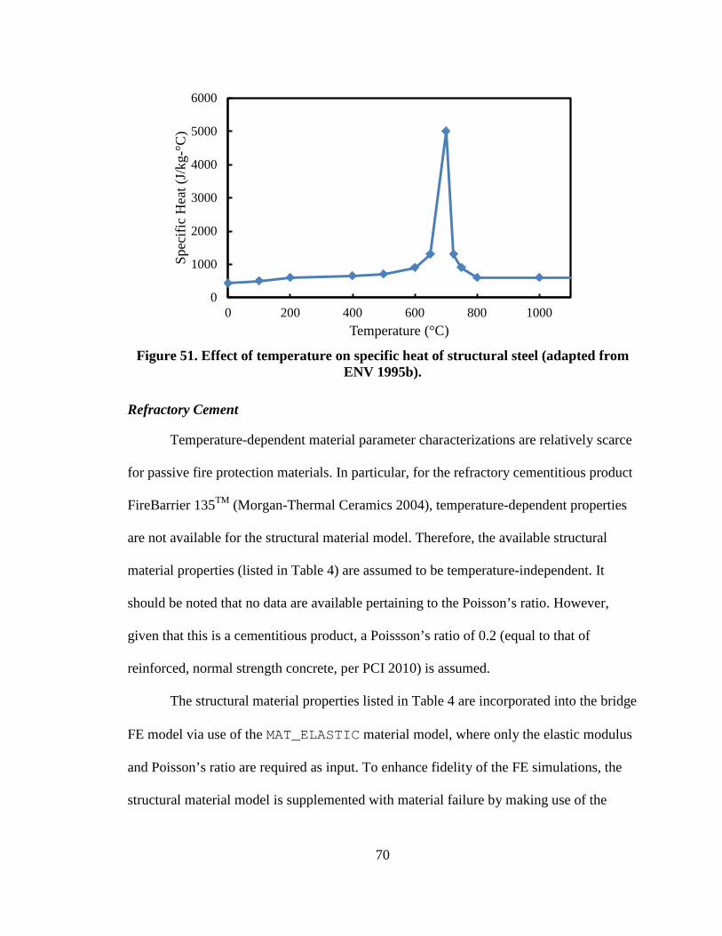
70
0
1000
2000
3000
4000
5000
6000
0 200 400 600 800 1000
Spec
ific
Hea
t (J/
kg-°
C)
Temperature (°C) Figure 51. Effect of temperature on specific heat of structural steel (adapted from
ENV 1995b).
Refractory Cement
Temperature-dependent material parameter characterizations are relatively scarce
for passive fire protection materials. In particular, for the refractory cementitious product
FireBarrier 135TM (Morgan-Thermal Ceramics 2004), temperature-dependent properties
are not available for the structural material model. Therefore, the available structural
material properties (listed in Table 4) are assumed to be temperature-independent. It
should be noted that no data are available pertaining to the Poisson’s ratio. However,
given that this is a cementitious product, a Poissson’s ratio of 0.2 (equal to that of
reinforced, normal strength concrete, per PCI 2010) is assumed.
The structural material properties listed in Table 4 are incorporated into the bridge
FE model via use of the MAT_ELASTIC material model, where only the elastic modulus
and Poisson’s ratio are required as input. To enhance fidelity of the FE simulations, the
structural material model is supplemented with material failure by making use of the
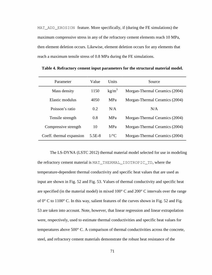
71
MAT_ADD_EROSION feature. More specifically, if (during the FE simulations) the
maximum compressive stress in any of the refractory cement elements reach 10 MPa,
then element deletion occurs. Likewise, element deletion occurs for any elements that
reach a maximum tensile stress of 0.8 MPa during the FE simulations.
Table 4. Refractory cement input parameters for the structural material model.
Parameter Value Units Source
Mass density 1150 kg/m3 Morgan-Thermal Ceramics (2004)
Elastic modulus 4050 MPa Morgan-Thermal Ceramics (2004)
Poisson’s ratio 0.2 N/A N/A
Tensile strength 0.8 MPa Morgan-Thermal Ceramics (2004)
Compressive strength 10 MPa Morgan-Thermal Ceramics (2004)
Coeff. thermal expansion 5.5E-8 1/°C Morgan-Thermal Ceramics (2004)
The LS-DYNA (LSTC 2012) thermal material model selected for use in modeling
the refractory cement material is MAT_THERMAL_ISOTROPIC_TD, where the
temperature-dependent thermal conductivity and specific heat values that are used as
input are shown in Fig. 52 and Fig. 53. Values of thermal conductivity and specific heat
are specified (in the material model) in mixed 100° C and 200° C intervals over the range
of 0° C to 1100° C. In this way, salient features of the curves shown in Fig. 52 and Fig.
53 are taken into account. Note, however, that linear regression and linear extrapolation
were, respectively, used to estimate thermal conductivities and specific heat values for
temperatures above 500° C. A comparison of thermal conductivities across the concrete,
steel, and refractory cement materials demonstrate the robust heat resistance of the
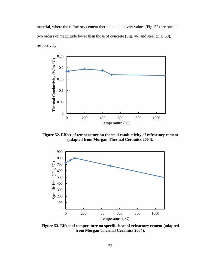
72
material, where the refractory cement thermal conductivity values (Fig. 52) are one and
two orders of magnitude lower than those of concrete (Fig. 46) and steel (Fig. 50),
respectively.
0
0.05
0.1
0.15
0.2
0.25
0 200 400 600 800 1000
Ther
mal
Con
duct
ivity
(W/m
-°C
)
Temperature (°C)
Figure 52. Effect of temperature on thermal conductivity of refractory cement (adapted from Morgan-Thermal Ceramics 2004).
0
100
200
300
400
500
600
700
800
900
0 200 400 600 800 1000
Spec
ific
Hea
t (J/
kg-°
C)
Temperature (°C) Figure 53. Effect of temperature on specific heat of refractory cement (adapted
from Morgan-Thermal Ceramics 2004).
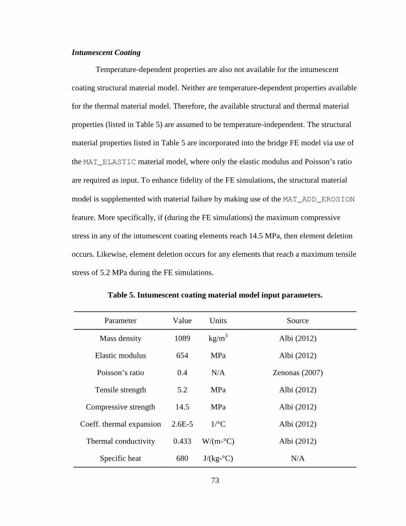
73
Intumescent Coating
Temperature-dependent properties are also not available for the intumescent
coating structural material model. Neither are temperature-dependent properties available
for the thermal material model. Therefore, the available structural and thermal material
properties (listed in Table 5) are assumed to be temperature-independent. The structural
material properties listed in Table 5 are incorporated into the bridge FE model via use of
the MAT_ELASTIC material model, where only the elastic modulus and Poisson’s ratio
are required as input. To enhance fidelity of the FE simulations, the structural material
model is supplemented with material failure by making use of the MAT_ADD_EROSION
feature. More specifically, if (during the FE simulations) the maximum compressive
stress in any of the intumescent coating elements reach 14.5 MPa, then element deletion
occurs. Likewise, element deletion occurs for any elements that reach a maximum tensile
stress of 5.2 MPa during the FE simulations.
Table 5. Intumescent coating material model input parameters.
Parameter Value Units Source
Mass density 1089 kg/m3 Albi (2012)
Elastic modulus 654 MPa Albi (2012)
Poisson’s ratio 0.4 N/A Zenonas (2007)
Tensile strength 5.2 MPa Albi (2012)
Compressive strength 14.5 MPa Albi (2012)
Coeff. thermal expansion 2.6E-5 1/°C Albi (2012)
Thermal conductivity 0.433 W/(m-°C) Albi (2012)
Specific heat 680 J/(kg-°C) N/A
74
The LS-DYNA (LSTC 2012) thermal material model selected for use in modeling
the intumescent coating material is MAT_THERMAL_ISOTROPIC_TD, where the
thermal conductivity value (which is assumed to be temperature-independent) is listed in
Table 5. Due to the relatively small thickness of the intumescent coating elements (1.3
mm), a correspondingly small mass of the material is modeled. Therefore, the FE
simulation results are not sensitive to the corresponding specific heat values that are
employed (Bartholmai et al. 2003), and a value of 680 J/(kg-°C) is assumed. A
comparison of thermal conductivities across the concrete, steel, and intumescent coating
materials demonstrate the robust heat resistance of the material, where the intumescent
coating thermal conductivity value (Table 5) is one and two orders of magnitude lower
than those concrete (Fig. 46) and steel (Fig. 50), respectively.
Determination of Severe-Fire Scenario
Due to the lack of established, standardized design-fire scenarios that can be used
in bridge fire-safety applications, constituent design-fire quantities are not directly
available for carrying out severe-fire assessments in the current study. Consequently, a
severe-fire scenario must be constructed from derived or estimated quantities. As
discussed above, the large hydrocarbon pool fire conditions given in the ASTM E1529
standard (ASTM 2001) have been shown to be consistent with forensic findings from the
2007 MacArthur Maze steel-girder bridge fire in northern California. Accordingly, the
fire conditions prescribed in ASTM E1529 are emulated, with respect to generation of
heat energy, in the steel-girder bridge passive fire protection assessments carried out for
the current study. Namely, fire-intensity and fire-duration quantities associated with the
burning of a fully-loaded (34,000 l) gasoline tank truck are derived based on data
75
available from the literature, material testing standards, and bridge-fire forensic findings.
Collectively, the derived quantities are used to generate thermal effects in simulations
carried out to determine the efficacy of passive fire protection materials for the selected
steel-girder bridge (i.e., the Lime Kiln overpass).
Of commensurate importance in constructing a fire scenario are the placement
and distribution of the fire ignition material (i.e., the volume of gasoline and the tank
truck). Given that no guidance is currently available in estimating the positioning of
vehicles for design-fire scenarios, the positioning of the gasoline tank truck for the
severe-fire assessments of the current study is defined in a manner that directly
corresponds to forensic findings from a 2011 tanker fire, which occurred directly beneath
the Lime Kiln Lane overpass (as discussed below). This approach is so elected, given the
fledgling state of bridge fire-safety, where use of past fire incidents at a bridge site has
been recognized as a viable means of determining representative fire scenarios for that
same site (Hurley and Bukowski 2008). Nonetheless, the effect of truck positioning (in
relation to the generation of bridge thermal demands) is identified as a worthwhile, future
research effort.
Lime Kiln Lane Overpass Fire (2011)
On June 7, 2011, during evening rush hour traffic, a tank truck containing septic
waste material caught fire (for unknown reasons) while traveling along I-71 N in eastern
Jefferson County, in north-central Kentucky (Fig. 54). Even though, typically, septic
waste is relatively less flammable than other tank-transported products such as gasoline,
the driver of the vehicle described the propagation of the fire as extremely rapid. The
period from ignition to engulfment of the truck was described by the driver as that of
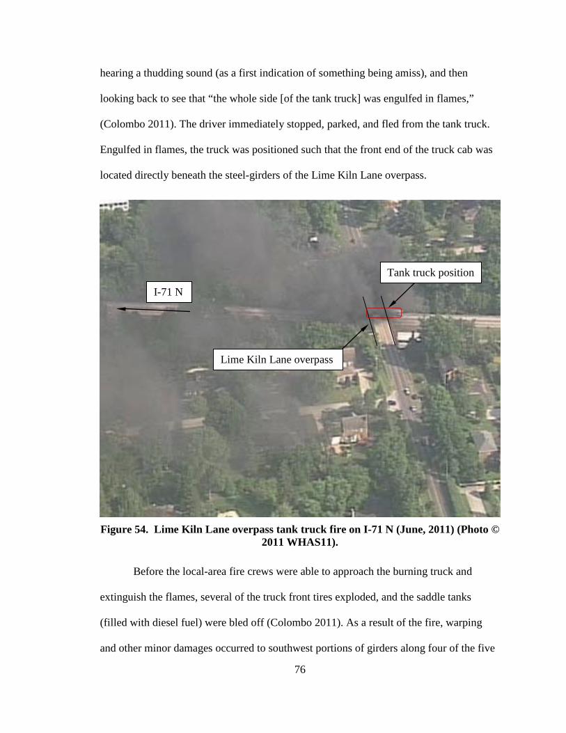
76
hearing a thudding sound (as a first indication of something being amiss), and then
looking back to see that “the whole side [of the tank truck] was engulfed in flames,”
(Colombo 2011). The driver immediately stopped, parked, and fled from the tank truck.
Engulfed in flames, the truck was positioned such that the front end of the truck cab was
located directly beneath the steel-girders of the Lime Kiln Lane overpass.
Figure 54. Lime Kiln Lane overpass tank truck fire on I-71 N (June, 2011) (Photo ©
2011 WHAS11).
Before the local-area fire crews were able to approach the burning truck and
extinguish the flames, several of the truck front tires exploded, and the saddle tanks
(filled with diesel fuel) were bled off (Colombo 2011). As a result of the fire, warping
and other minor damages occurred to southwest portions of girders along four of the five
Lime Kiln Lane overpass
Tank truck position
I-71 N
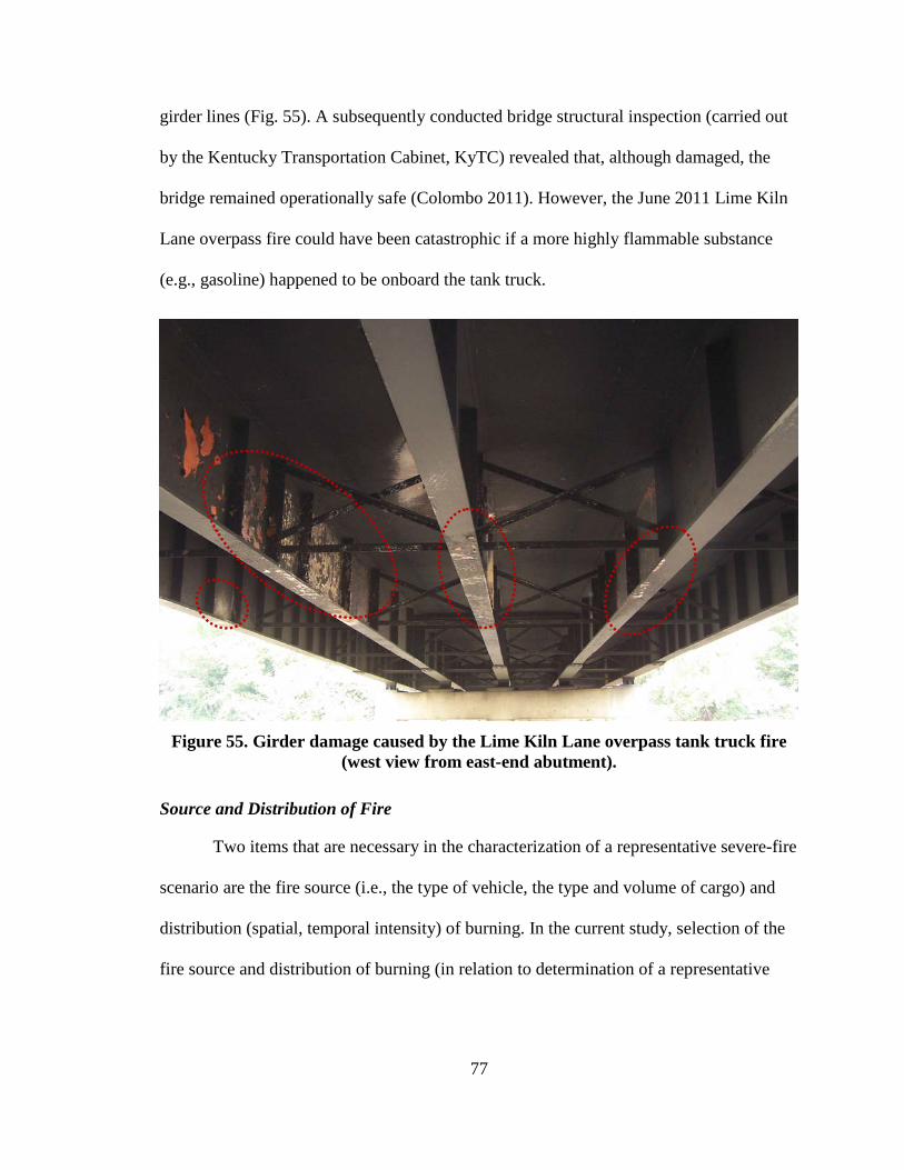
77
girder lines (Fig. 55). A subsequently conducted bridge structural inspection (carried out
by the Kentucky Transportation Cabinet, KyTC) revealed that, although damaged, the
bridge remained operationally safe (Colombo 2011). However, the June 2011 Lime Kiln
Lane overpass fire could have been catastrophic if a more highly flammable substance
(e.g., gasoline) happened to be onboard the tank truck.
Figure 55. Girder damage caused by the Lime Kiln Lane overpass tank truck fire
(west view from east-end abutment).
Source and Distribution of Fire
Two items that are necessary in the characterization of a representative severe-fire
scenario are the fire source (i.e., the type of vehicle, the type and volume of cargo) and
distribution (spatial, temporal intensity) of burning. In the current study, selection of the
fire source and distribution of burning (in relation to determination of a representative
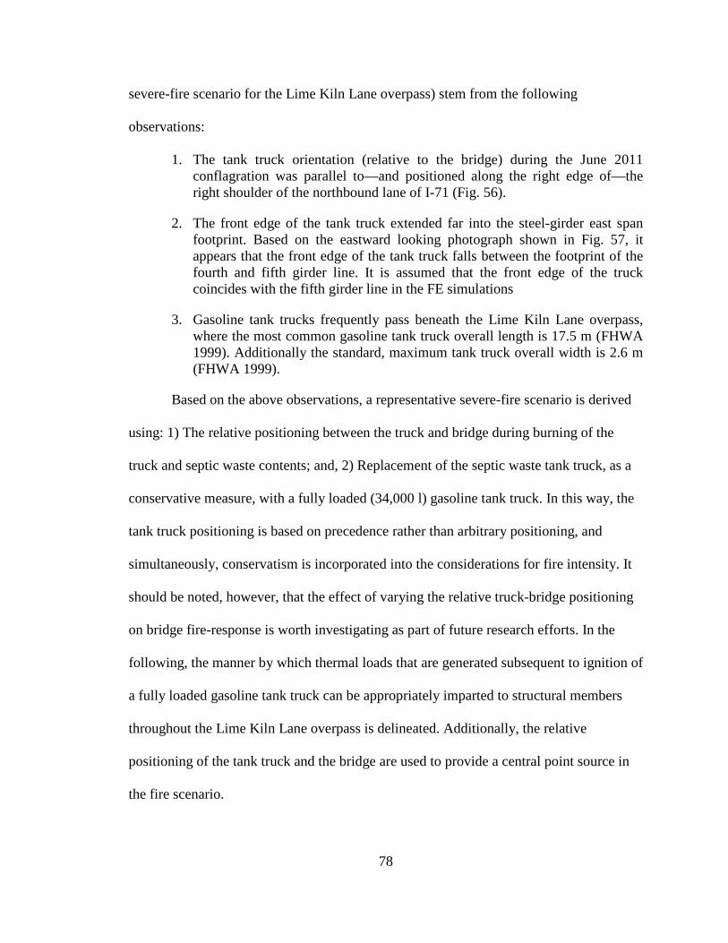
78
severe-fire scenario for the Lime Kiln Lane overpass) stem from the following
observations:
1. The tank truck orientation (relative to the bridge) during the June 2011 conflagration was parallel to—and positioned along the right edge of—the right shoulder of the northbound lane of I-71 (Fig. 56).
2. The front edge of the tank truck extended far into the steel-girder east span footprint. Based on the eastward looking photograph shown in Fig. 57, it appears that the front edge of the tank truck falls between the footprint of the fourth and fifth girder line. It is assumed that the front edge of the truck coincides with the fifth girder line in the FE simulations
3. Gasoline tank trucks frequently pass beneath the Lime Kiln Lane overpass, where the most common gasoline tank truck overall length is 17.5 m (FHWA 1999). Additionally the standard, maximum tank truck overall width is 2.6 m (FHWA 1999).
Based on the above observations, a representative severe-fire scenario is derived
using: 1) The relative positioning between the truck and bridge during burning of the
truck and septic waste contents; and, 2) Replacement of the septic waste tank truck, as a
conservative measure, with a fully loaded (34,000 l) gasoline tank truck. In this way, the
tank truck positioning is based on precedence rather than arbitrary positioning, and
simultaneously, conservatism is incorporated into the considerations for fire intensity. It
should be noted, however, that the effect of varying the relative truck-bridge positioning
on bridge fire-response is worth investigating as part of future research efforts. In the
following, the manner by which thermal loads that are generated subsequent to ignition of
a fully loaded gasoline tank truck can be appropriately imparted to structural members
throughout the Lime Kiln Lane overpass is delineated. Additionally, the relative
positioning of the tank truck and the bridge are used to provide a central point source in
the fire scenario.
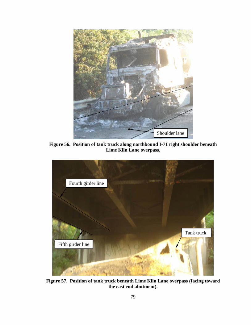
79
Figure 56. Position of tank truck along northbound I-71 right shoulder beneath
Lime Kiln Lane overpass.
Figure 57. Position of tank truck beneath Lime Kiln Lane overpass (facing toward
the east end abutment).
Tank truck
Shoulder lane
Fourth girder line
Fifth girder line
80
For gasoline tank truck fires, burning progresses via the spillage and ignition of
flammable liquid onto the nearby ground surface (as was the case in the 2007 MacArthur
Maze fire in northern California). Flames that arise from the large open-air hydrocarbon
pool transmit heat energy predominately through spatially (and temporally) varying
thermal radiation. Consequently, bridge structural members are subjected to elevated
temperatures, in part, as a function of member distance from the luminous flame region
that emanates from the spilled pool of gasoline. Given the varying distances that bridge
structural members (e.g., steel-girders) may hold at the onset of fire, not all members (or
portions of members) are subjected to the same time-varying temperatures. Therefore, the
time-temperature curve associated with the ASTM E1529 standard (recall Fig. 22) is not
directly employed in the severe-fire FE simulations.
Instead, the total heat release rate associated with the burning of a fully loaded
gasoline tank truck is used to facilitate the prescription of thermal loads throughout the
bridge FE model. The quantity, heat release rate (HRR), can be defined as the emission of
heat energy (i.e., fire intensity) emanating from a given fire source, and has been
recognized as the single-most important variable in determining fire hazard effects
(Babrauskas and Peacock 1992). The peak HRR values associated with the burning of
vehicles of various size (and cargo load) within roadway tunnels have been estimated
based on full-scale experiments (these rates are catalogued in Ingason 2006). Of the
greatest severity among the published rates is the peak-value HRR corresponding to a
gasoline tank truck fire, which has been estimated to be 300 MW (NCHRP 2011).
Thermal loading is incorporated into the Lime Kiln Lane overpass FE model by,
first, assuming that a circular pool of gasoline has spilled and become uniformly
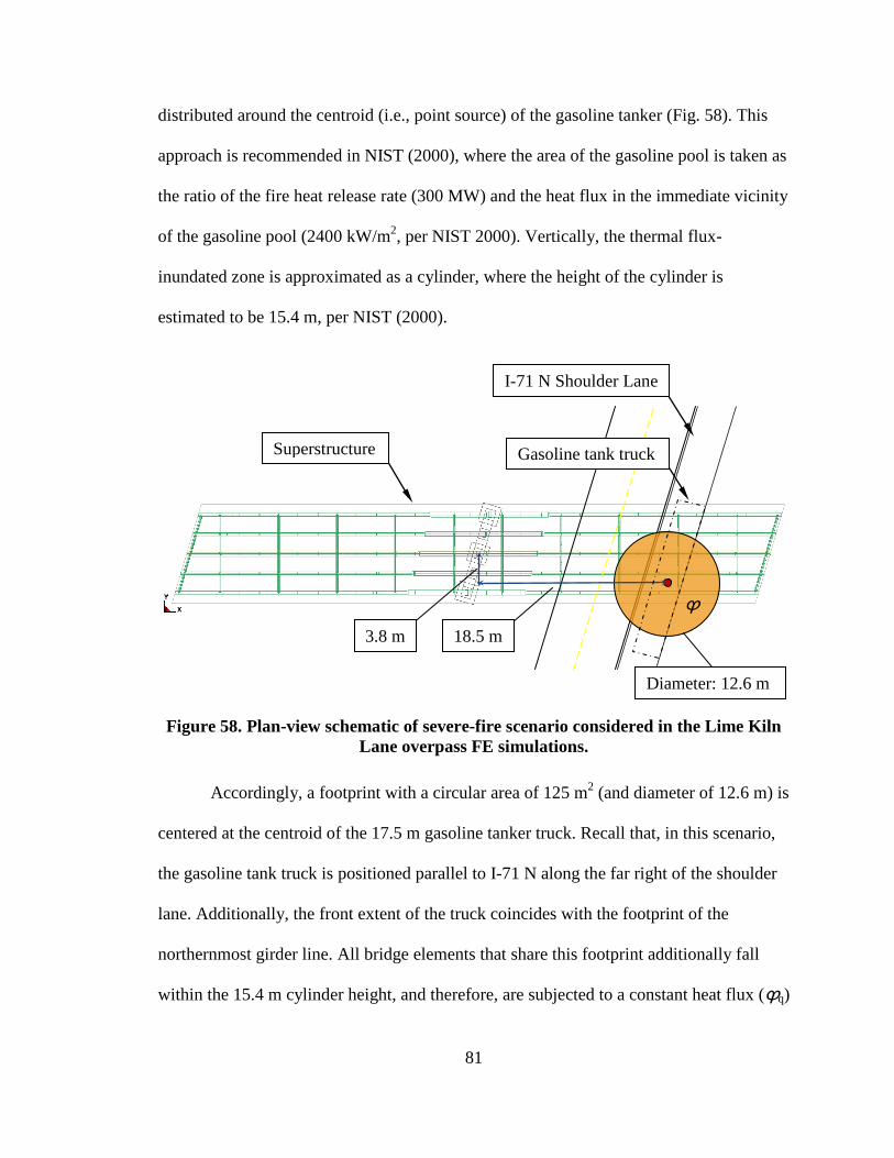
81
distributed around the centroid (i.e., point source) of the gasoline tanker (Fig. 58). This
approach is recommended in NIST (2000), where the area of the gasoline pool is taken as
the ratio of the fire heat release rate (300 MW) and the heat flux in the immediate vicinity
of the gasoline pool (2400 kW/m2, per NIST 2000). Vertically, the thermal flux-
inundated zone is approximated as a cylinder, where the height of the cylinder is
estimated to be 15.4 m, per NIST (2000).
Figure 58. Plan-view schematic of severe-fire scenario considered in the Lime Kiln Lane overpass FE simulations.
Accordingly, a footprint with a circular area of 125 m2 (and diameter of 12.6 m) is
centered at the centroid of the 17.5 m gasoline tanker truck. Recall that, in this scenario,
the gasoline tank truck is positioned parallel to I-71 N along the far right of the shoulder
lane. Additionally, the front extent of the truck coincides with the footprint of the
northernmost girder line. All bridge elements that share this footprint additionally fall
within the 15.4 m cylinder height, and therefore, are subjected to a constant heat flux (ϕq)
Superstructure
I-71 N Shoulder Lane
3.8 m 18.5 m
Diameter: 12.6 m
ϕ
Gasoline tank truck

82
of 158 kW/m2, where this constant heat flux is stipulated in ASTM E1529 (ASTM 2001).
Recall that the heat flux of 158 kW/m2 is representative of continuous engulfment within
the luminous flame region of a large hydrocarbon pool fire (ASTM 2001).
83
ANALYTICAL ASSESSMENT OF PASSIVE FIRE PROTECTION ON THE LIME KILN LANE OVERPASS
Overview
For the coupled thermal-mechanical FE simulations of a gasoline tank truck fire
that occurs beneath the Lime Kiln Lane overpass, four simulations are conducted:
1. Mechanical loading of the unprotected bridge structure.
2. Mechanical and thermal loading of the unprotected bridge structure.
3. Mechanical and thermal loading of the bridge structure when fitted with refractory cement passive fire protection.
4. Mechanical and thermal loading of the bridge structure when fitted with intumescent coating passive fire protection.
Bridge responses predicted from the structural and coupled thermal-mechanical FEA are
presented below, with emphasis placed on the behavior of the A36 structural steel plate
girders.
Duration of Analysis
By default, the LS-DYNA software employs an explicit time-stepping algorithm
in calculating nodal motions and stresses. Entailed in explicit time-stepping is the
division of each analysis time unit (sec are used in the current study) into millions of
discrete intervals (or more). However, because the Lime Kiln Lane overpass contains
31,072 nonlinear thermal-shell elements, and 53,157 nonlinear solid elements, use of
explicit time stepping to conduct a simulation of more than several seconds in (simulated)
duration is infeasible. Therefore, the use of implicit transient dynamic time-stepping is
employed in the FEA, where individual time steps are more computationally expensive,
but can be several orders of magnitude larger than the explicit time-step counterparts.
84
For the analyses conducted, a default trial time step of 0.1 sec is prescribed. If, for
any time-step, this time-step size does not converge to within acceptable system
equilibrium tolerances (which are internally calculated), the automatic time-step
determination algorithm in LS-DYNA reduces the trial time-step. This process continues
until an acceptable equilibrium calculation is made for the iteratively determined time-
step, and then reset to 0.1 sec to begin the next time-step calculation sequence.
Use of the implicit time-stepping feature in LS-DYNA (LSTC 2011) enabled the
FE bridge-fire simulation to be carried out up to a total (simulated) duration of 20 min.
(of simulated fire exposure) for each analysis case. In the event that catastrophic bridge
failure occurs prior to 20 min., then the analysis is halted. While the ASTM E1529 testing
standard stipulates that the fire duration consist of 120 min., the shorter duration time of
20 min. was selected as a means of leveraging computational resource practicality and a
fire-exposure duration that is of interest based on previous studies and forensic findings.
Namely, the steel-girder bridge-fire FEA conducted by Payá-Zaforteza and Garlock
(2010) revealed that bridge collapse (of unprotected bridges) occurred within a few
minutes of high-temperature loading. Similarly, Choi (2008) found that coupled thermal-
mechanical FEA using a simplified Mac Arthur Maze bridge FE model and gasoline tank
truck fire conditions gave predictions of collapse within 20 min. of fire ignition. The
analytical findings of Choi (2008), with respect to time-to-collapse, are consistent with
forensic findings from an investigation into the fire-induced collapse of the MacArthur
Maze overpass (Dunn and Chowdhury 2009). analyses in conjunction with the LS-
DYNA feature of automatic time step determination (LSTC 2011).
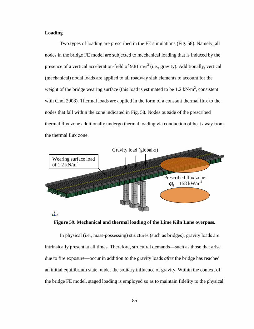
85
Loading
Two types of loading are prescribed in the FE simulations (Fig. 58). Namely, all
nodes in the bridge FE model are subjected to mechanical loading that is induced by the
presence of a vertical acceleration-field of 9.81 m/s2 (i.e., gravity). Additionally, vertical
(mechanical) nodal loads are applied to all roadway slab elements to account for the
weight of the bridge wearing surface (this load is estimated to be 1.2 kN/m2, consistent
with Choi 2008). Thermal loads are applied in the form of a constant thermal flux to the
nodes that fall within the zone indicated in Fig. 58. Nodes outside of the prescribed
thermal flux zone additionally undergo thermal loading via conduction of heat away from
the thermal flux zone.
Figure 59. Mechanical and thermal loading of the Lime Kiln Lane overpass.
In physical (i.e., mass-possessing) structures (such as bridges), gravity loads are
intrinsically present at all times. Therefore, structural demands—such as those that arise
due to fire exposure—occur in addition to the gravity loads after the bridge has reached
an initial equilibrium state, under the solitary influence of gravity. Within the context of
the bridge FE model, staged loading is employed so as to maintain fidelity to the physical
Wearing surface load of 1.2 kN/m2
Prescribed flux zone: ϕq = 158 kW/m2
Gravity load (global-z)
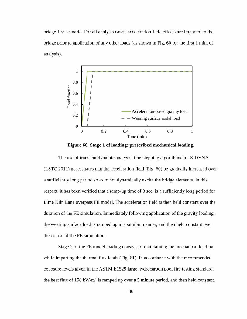
86
bridge-fire scenario. For all analysis cases, acceleration-field effects are imparted to the
bridge prior to application of any other loads (as shown in Fig. 60 for the first 1 min. of
analysis).
0
0.2
0.4
0.6
0.8
1
0 0.2 0.4 0.6 0.8 1
Load
frac
tion
Time (min)
Acceleration-based gravity loadWearing surface nodal load
Figure 60. Stage 1 of loading: prescribed mechanical loading.
The use of transient dynamic analysis time-stepping algorithms in LS-DYNA
(LSTC 2011) necessitates that the acceleration field (Fig. 60) be gradually increased over
a sufficiently long period so as to not dynamically excite the bridge elements. In this
respect, it has been verified that a ramp-up time of 3 sec. is a sufficiently long period for
Lime Kiln Lane overpass FE model. The acceleration field is then held constant over the
duration of the FE simulation. Immediately following application of the gravity loading,
the wearing surface load is ramped up in a similar manner, and then held constant over
the course of the FE simulation.
Stage 2 of the FE model loading consists of maintaining the mechanical loading
while imparting the thermal flux loads (Fig. 61). In accordance with the recommended
exposure levels given in the ASTM E1529 large hydrocarbon pool fire testing standard,
the heat flux of 158 kW/m2 is ramped up over a 5 minute period, and then held constant.
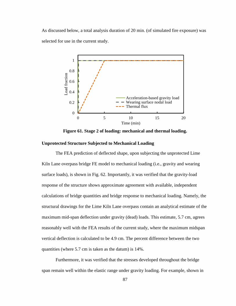
87
As discussed below, a total analysis duration of 20 min. (of simulated fire exposure) was
selected for use in the current study.
0
0.2
0.4
0.6
0.8
1
0 5 10 15 20
Load
frac
tion
Time (min)
Acceleration-based gravity loadWearing surface nodal loadThermal flux
Figure 61. Stage 2 of loading: mechanical and thermal loading.
Unprotected Structure Subjected to Mechanical Loading
The FEA prediction of deflected shape, upon subjecting the unprotected Lime
Kiln Lane overpass bridge FE model to mechanical loading (i.e., gravity and wearing
surface loads), is shown in Fig. 62. Importantly, it was verified that the gravity-load
response of the structure shows approximate agreement with available, independent
calculations of bridge quantities and bridge response to mechanical loading. Namely, the
structural drawings for the Lime Kiln Lane overpass contain an analytical estimate of the
maximum mid-span deflection under gravity (dead) loads. This estimate, 5.7 cm, agrees
reasonably well with the FEA results of the current study, where the maximum midspan
vertical deflection is calculated to be 4.9 cm. The percent difference between the two
quantities (where 5.7 cm is taken as the datum) is 14%.
Furthermore, it was verified that the stresses developed throughout the bridge
span remain well within the elastic range under gravity loading. For example, shown in
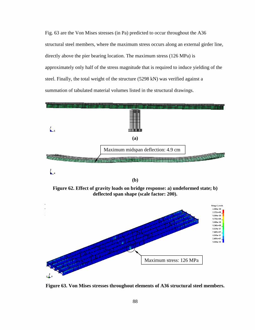
88
Fig. 63 are the Von Mises stresses (in Pa) predicted to occur throughout the A36
structural steel members, where the maximum stress occurs along an external girder line,
directly above the pier bearing location. The maximum stress (126 MPa) is
approximately only half of the stress magnitude that is required to induce yielding of the
steel. Finally, the total weight of the structure (5298 kN) was verified against a
summation of tabulated material volumes listed in the structural drawings.
(a)
(b)
Figure 62. Effect of gravity loads on bridge response: a) undeformed state; b) deflected span shape (scale factor: 200).
Figure 63. Von Mises stresses throughout elements of A36 structural steel members.
Maximum midspan deflection: 4.9 cm
Maximum stress: 126 MPa
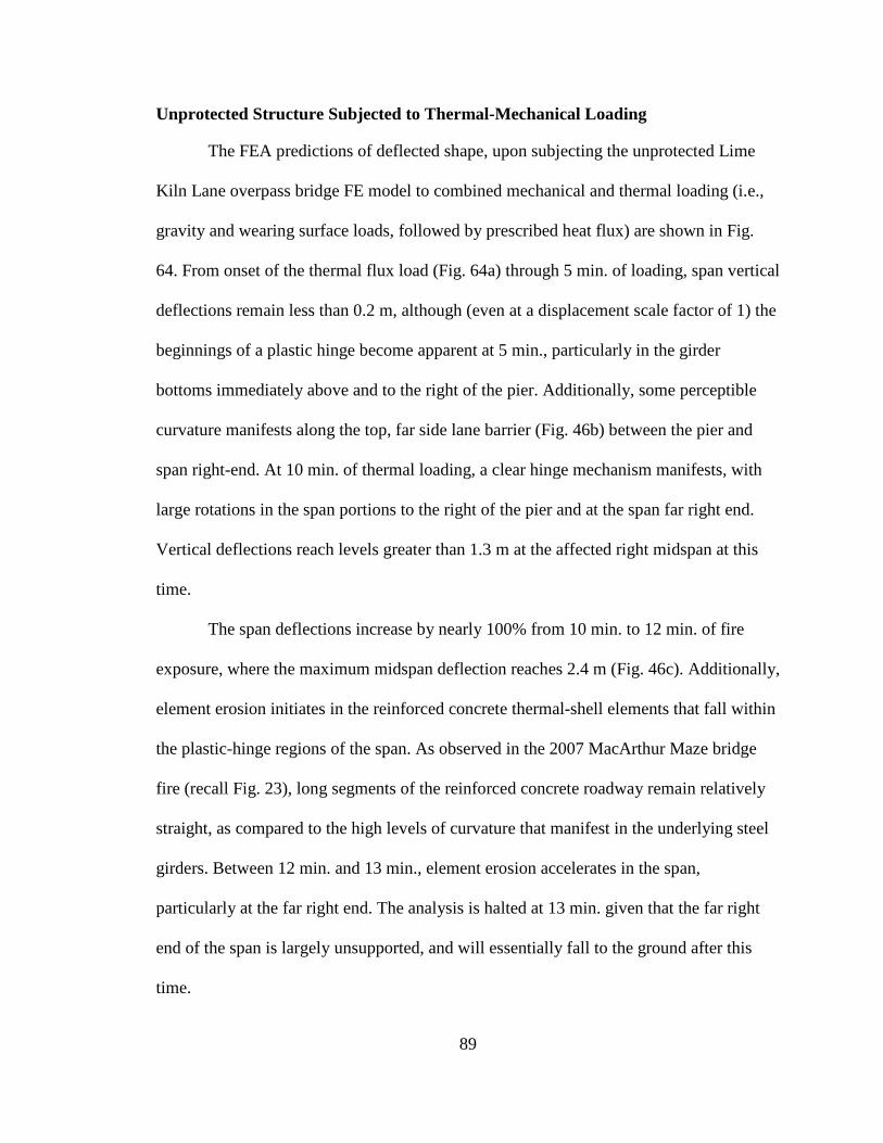
89
Unprotected Structure Subjected to Thermal-Mechanical Loading
The FEA predictions of deflected shape, upon subjecting the unprotected Lime
Kiln Lane overpass bridge FE model to combined mechanical and thermal loading (i.e.,
gravity and wearing surface loads, followed by prescribed heat flux) are shown in Fig.
64. From onset of the thermal flux load (Fig. 64a) through 5 min. of loading, span vertical
deflections remain less than 0.2 m, although (even at a displacement scale factor of 1) the
beginnings of a plastic hinge become apparent at 5 min., particularly in the girder
bottoms immediately above and to the right of the pier. Additionally, some perceptible
curvature manifests along the top, far side lane barrier (Fig. 46b) between the pier and
span right-end. At 10 min. of thermal loading, a clear hinge mechanism manifests, with
large rotations in the span portions to the right of the pier and at the span far right end.
Vertical deflections reach levels greater than 1.3 m at the affected right midspan at this
time.
The span deflections increase by nearly 100% from 10 min. to 12 min. of fire
exposure, where the maximum midspan deflection reaches 2.4 m (Fig. 46c). Additionally,
element erosion initiates in the reinforced concrete thermal-shell elements that fall within
the plastic-hinge regions of the span. As observed in the 2007 MacArthur Maze bridge
fire (recall Fig. 23), long segments of the reinforced concrete roadway remain relatively
straight, as compared to the high levels of curvature that manifest in the underlying steel
girders. Between 12 min. and 13 min., element erosion accelerates in the span,
particularly at the far right end. The analysis is halted at 13 min. given that the far right
end of the span is largely unsupported, and will essentially fall to the ground after this
time.
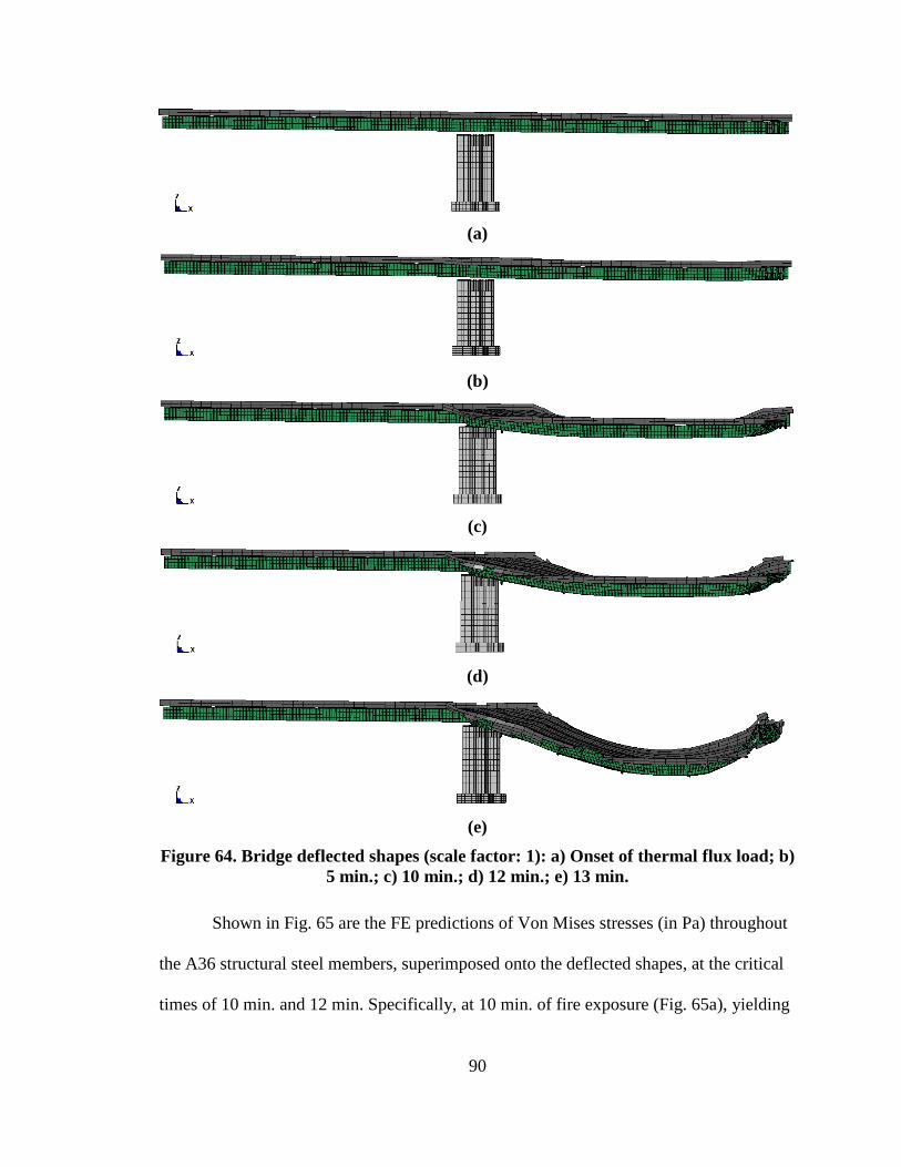
90
(a)
(b)
(c)
(d)
(e)
Figure 64. Bridge deflected shapes (scale factor: 1): a) Onset of thermal flux load; b) 5 min.; c) 10 min.; d) 12 min.; e) 13 min.
Shown in Fig. 65 are the FE predictions of Von Mises stresses (in Pa) throughout
the A36 structural steel members, superimposed onto the deflected shapes, at the critical
times of 10 min. and 12 min. Specifically, at 10 min. of fire exposure (Fig. 65a), yielding
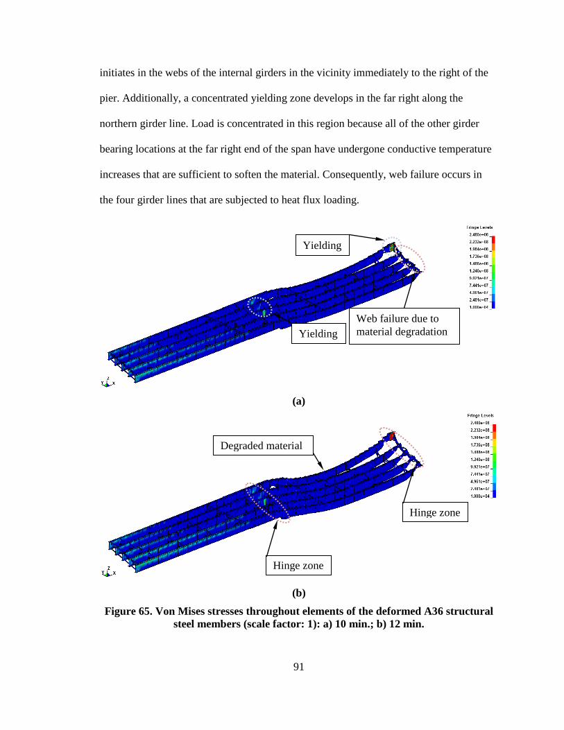
91
initiates in the webs of the internal girders in the vicinity immediately to the right of the
pier. Additionally, a concentrated yielding zone develops in the far right along the
northern girder line. Load is concentrated in this region because all of the other girder
bearing locations at the far right end of the span have undergone conductive temperature
increases that are sufficient to soften the material. Consequently, web failure occurs in
the four girder lines that are subjected to heat flux loading.
(a)
(b)
Figure 65. Von Mises stresses throughout elements of the deformed A36 structural steel members (scale factor: 1): a) 10 min.; b) 12 min.
Yielding
Web failure due to material degradation Yielding
Hinge zone
Hinge zone
Degraded material
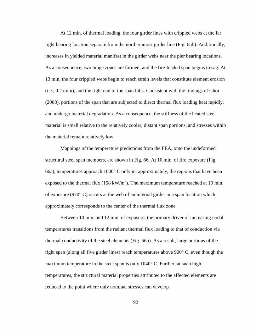
92
At 12 min. of thermal loading, the four girder lines with crippled webs at the far
right bearing location separate from the northernmost girder line (Fig. 65b). Additionally,
increases in yielded material manifest in the girder webs near the pier bearing locations.
As a consequence, two hinge zones are formed, and the fire-loaded span begins to sag. At
13 min, the four crippled webs begin to reach strain levels that constitute element erosion
(i.e., 0.2 m/m), and the right end of the span falls. Consistent with the findings of Choi
(2008), portions of the span that are subjected to direct thermal flux loading heat rapidly,
and undergo material degradation. As a consequence, the stiffness of the heated steel
material is small relative to the relatively cooler, distant span portions, and stresses within
the material remain relatively low.
Mappings of the temperature predictions from the FEA, onto the undeformed
structural steel span members, are shown in Fig. 66. At 10 min. of fire exposure (Fig.
66a), temperatures approach 1000° C only in, approximately, the regions that have been
exposed to the thermal flux (158 kW/m2). The maximum temperature reached at 10 min.
of exposure (970° C) occurs at the web of an internal girder in a span location which
approximately corresponds to the center of the thermal flux zone.
Between 10 min. and 12 min. of exposure, the primary driver of increasing nodal
temperatures transitions from the radiant thermal flux loading to that of conduction via
thermal conductivity of the steel elements (Fig. 66b). As a result, large portions of the
right span (along all five girder lines) reach temperatures above 900° C, even though the
maximum temperature in the steel span is only 1040° C. Further, at such high
temperatures, the structural material properties attributed to the affected elements are
reduced to the point where only nominal stresses can develop.
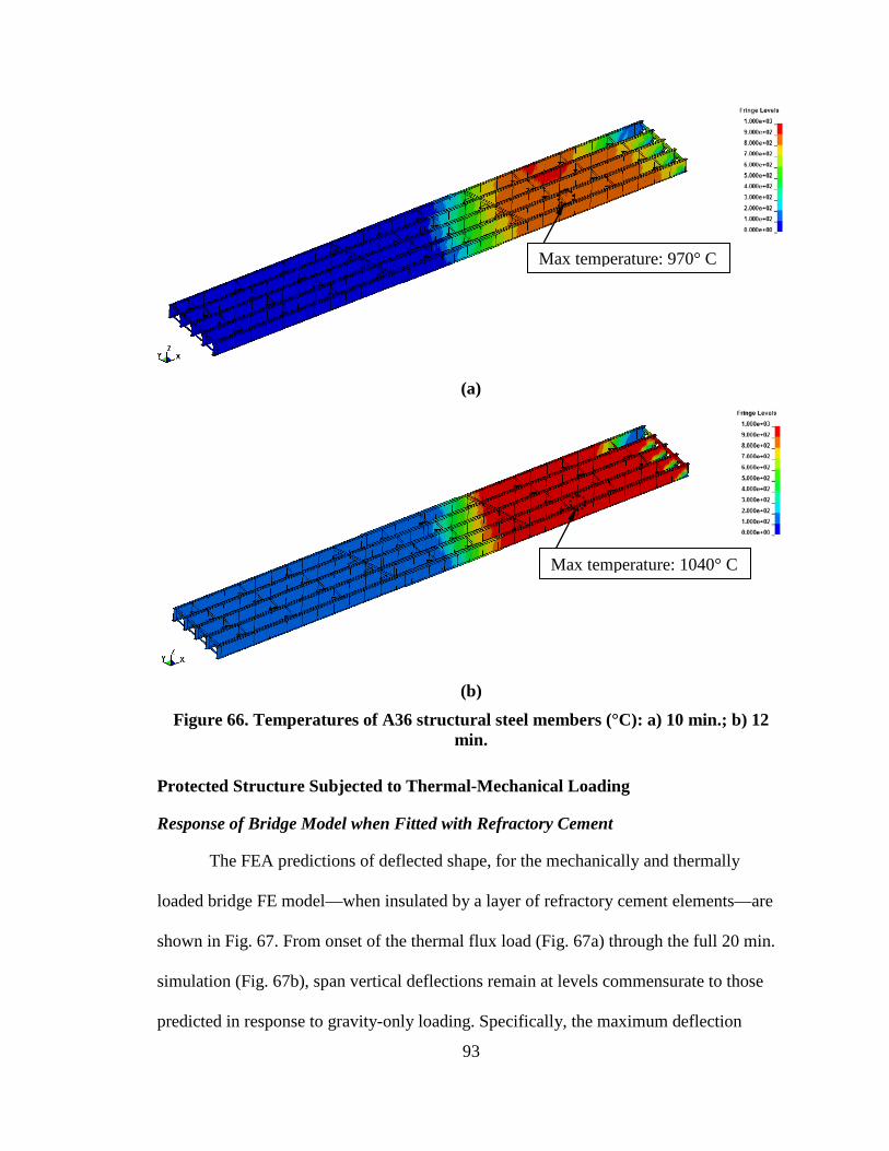
93
(a)
(b)
Figure 66. Temperatures of A36 structural steel members (°C): a) 10 min.; b) 12 min.
Protected Structure Subjected to Thermal-Mechanical Loading
Response of Bridge Model when Fitted with Refractory Cement
The FEA predictions of deflected shape, for the mechanically and thermally
loaded bridge FE model—when insulated by a layer of refractory cement elements—are
shown in Fig. 67. From onset of the thermal flux load (Fig. 67a) through the full 20 min.
simulation (Fig. 67b), span vertical deflections remain at levels commensurate to those
predicted in response to gravity-only loading. Specifically, the maximum deflection
Max temperature: 970° C
Max temperature: 1040° C
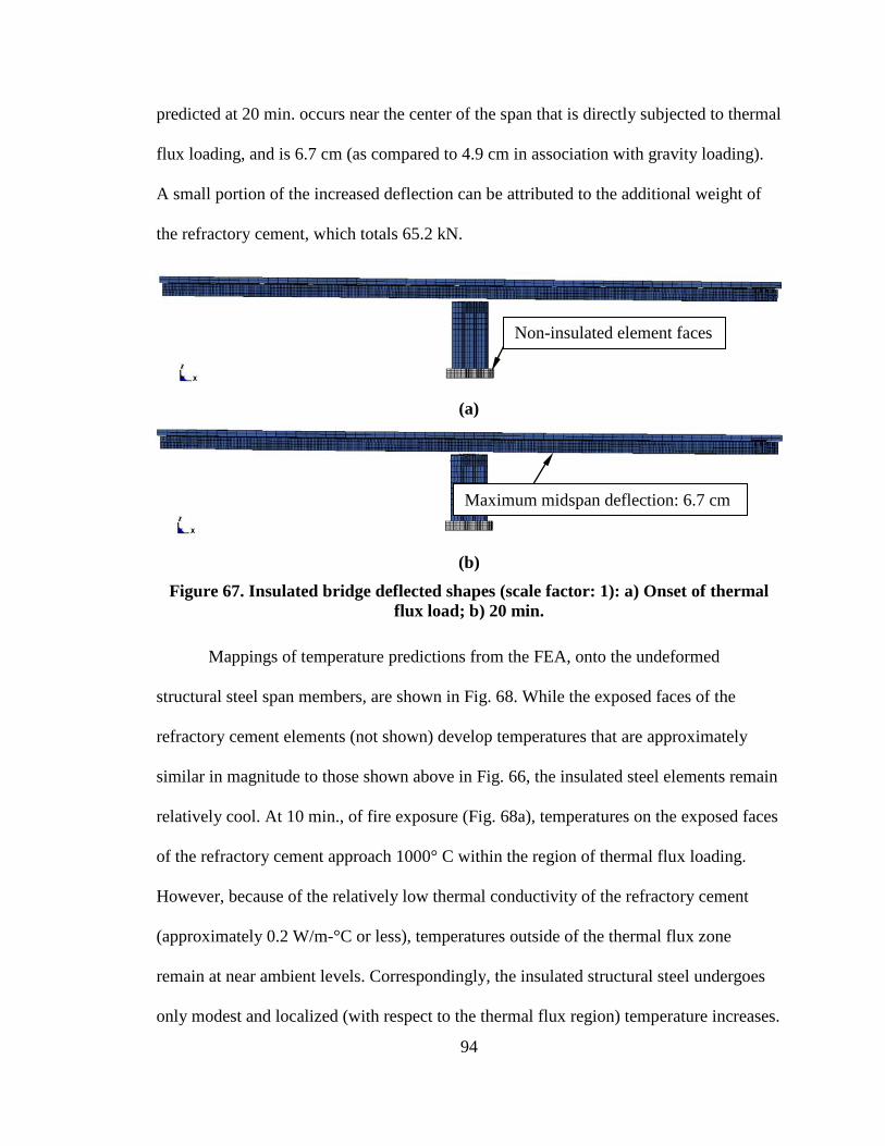
94
predicted at 20 min. occurs near the center of the span that is directly subjected to thermal
flux loading, and is 6.7 cm (as compared to 4.9 cm in association with gravity loading).
A small portion of the increased deflection can be attributed to the additional weight of
the refractory cement, which totals 65.2 kN.
(a)
(b)
Figure 67. Insulated bridge deflected shapes (scale factor: 1): a) Onset of thermal flux load; b) 20 min.
Mappings of temperature predictions from the FEA, onto the undeformed
structural steel span members, are shown in Fig. 68. While the exposed faces of the
refractory cement elements (not shown) develop temperatures that are approximately
similar in magnitude to those shown above in Fig. 66, the insulated steel elements remain
relatively cool. At 10 min., of fire exposure (Fig. 68a), temperatures on the exposed faces
of the refractory cement approach 1000° C within the region of thermal flux loading.
However, because of the relatively low thermal conductivity of the refractory cement
(approximately 0.2 W/m-°C or less), temperatures outside of the thermal flux zone
remain at near ambient levels. Correspondingly, the insulated structural steel undergoes
only modest and localized (with respect to the thermal flux region) temperature increases.
Non-insulated element faces
Maximum midspan deflection: 6.7 cm
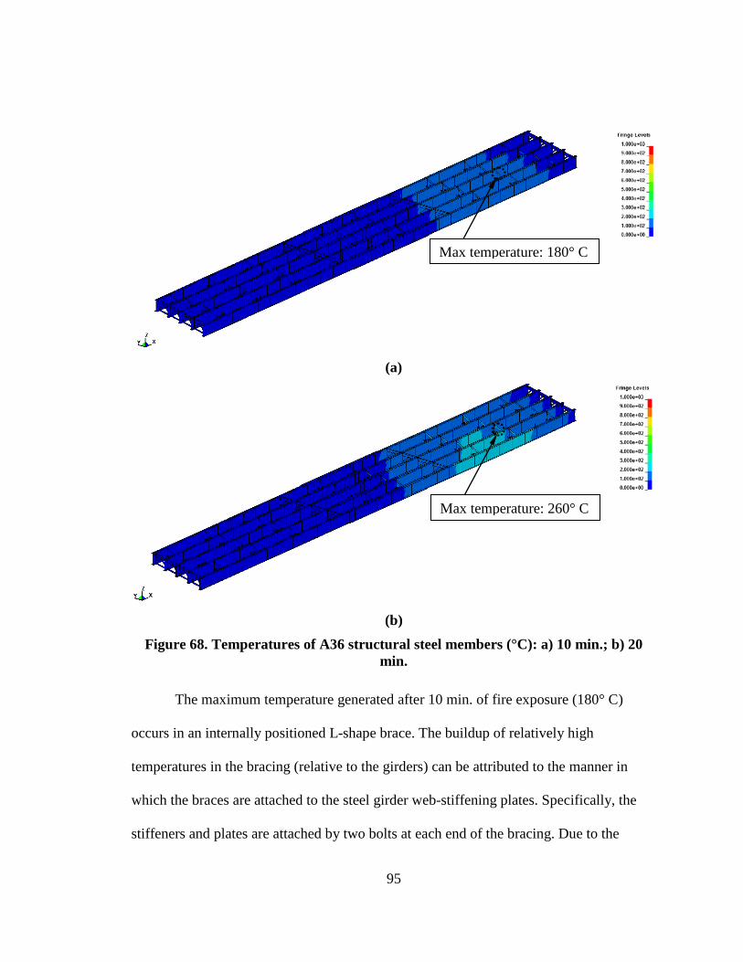
95
(a)
(b)
Figure 68. Temperatures of A36 structural steel members (°C): a) 10 min.; b) 20 min.
The maximum temperature generated after 10 min. of fire exposure (180° C)
occurs in an internally positioned L-shape brace. The buildup of relatively high
temperatures in the bracing (relative to the girders) can be attributed to the manner in
which the braces are attached to the steel girder web-stiffening plates. Specifically, the
stiffeners and plates are attached by two bolts at each end of the bracing. Due to the
Max temperature: 180° C
Max temperature: 260° C
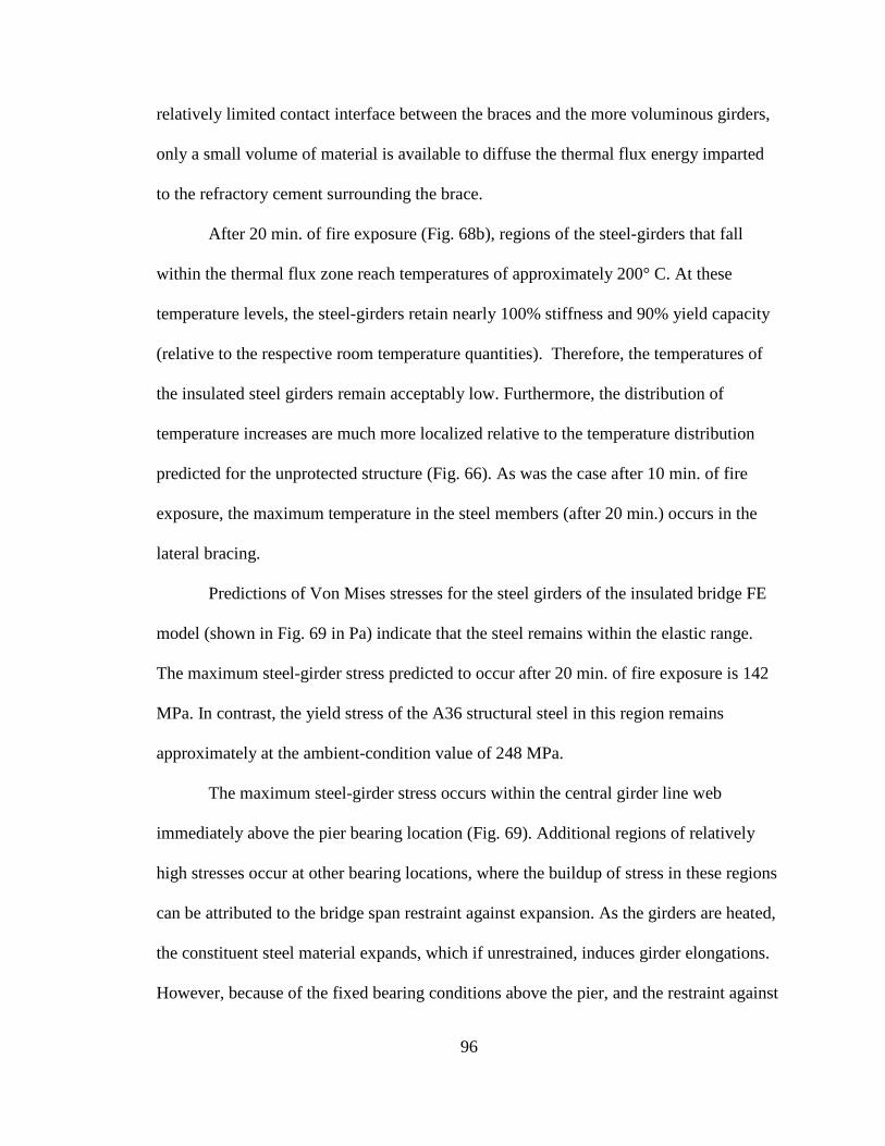
96
relatively limited contact interface between the braces and the more voluminous girders,
only a small volume of material is available to diffuse the thermal flux energy imparted
to the refractory cement surrounding the brace.
After 20 min. of fire exposure (Fig. 68b), regions of the steel-girders that fall
within the thermal flux zone reach temperatures of approximately 200° C. At these
temperature levels, the steel-girders retain nearly 100% stiffness and 90% yield capacity
(relative to the respective room temperature quantities). Therefore, the temperatures of
the insulated steel girders remain acceptably low. Furthermore, the distribution of
temperature increases are much more localized relative to the temperature distribution
predicted for the unprotected structure (Fig. 66). As was the case after 10 min. of fire
exposure, the maximum temperature in the steel members (after 20 min.) occurs in the
lateral bracing.
Predictions of Von Mises stresses for the steel girders of the insulated bridge FE
model (shown in Fig. 69 in Pa) indicate that the steel remains within the elastic range.
The maximum steel-girder stress predicted to occur after 20 min. of fire exposure is 142
MPa. In contrast, the yield stress of the A36 structural steel in this region remains
approximately at the ambient-condition value of 248 MPa.
The maximum steel-girder stress occurs within the central girder line web
immediately above the pier bearing location (Fig. 69). Additional regions of relatively
high stresses occur at other bearing locations, where the buildup of stress in these regions
can be attributed to the bridge span restraint against expansion. As the girders are heated,
the constituent steel material expands, which if unrestrained, induces girder elongations.
However, because of the fixed bearing conditions above the pier, and the restraint against
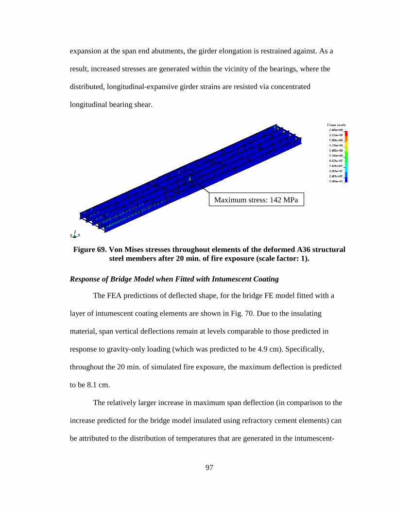
97
expansion at the span end abutments, the girder elongation is restrained against. As a
result, increased stresses are generated within the vicinity of the bearings, where the
distributed, longitudinal-expansive girder strains are resisted via concentrated
longitudinal bearing shear.
Figure 69. Von Mises stresses throughout elements of the deformed A36 structural
steel members after 20 min. of fire exposure (scale factor: 1).
Response of Bridge Model when Fitted with Intumescent Coating
The FEA predictions of deflected shape, for the bridge FE model fitted with a
layer of intumescent coating elements are shown in Fig. 70. Due to the insulating
material, span vertical deflections remain at levels comparable to those predicted in
response to gravity-only loading (which was predicted to be 4.9 cm). Specifically,
throughout the 20 min. of simulated fire exposure, the maximum deflection is predicted
to be 8.1 cm.
The relatively larger increase in maximum span deflection (in comparison to the
increase predicted for the bridge model insulated using refractory cement elements) can
be attributed to the distribution of temperatures that are generated in the intumescent-
Maximum stress: 142 MPa
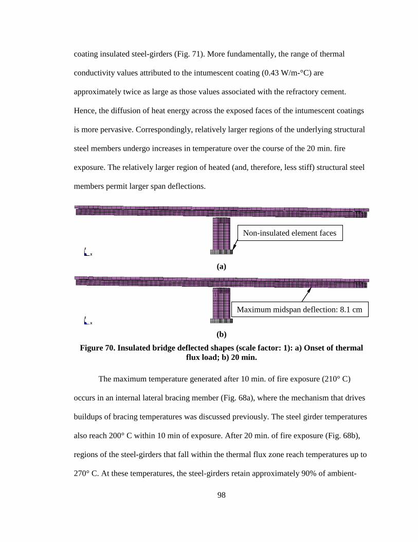
98
coating insulated steel-girders (Fig. 71). More fundamentally, the range of thermal
conductivity values attributed to the intumescent coating (0.43 W/m-°C) are
approximately twice as large as those values associated with the refractory cement.
Hence, the diffusion of heat energy across the exposed faces of the intumescent coatings
is more pervasive. Correspondingly, relatively larger regions of the underlying structural
steel members undergo increases in temperature over the course of the 20 min. fire
exposure. The relatively larger region of heated (and, therefore, less stiff) structural steel
members permit larger span deflections.
(a)
(b)
Figure 70. Insulated bridge deflected shapes (scale factor: 1): a) Onset of thermal flux load; b) 20 min.
The maximum temperature generated after 10 min. of fire exposure (210° C)
occurs in an internal lateral bracing member (Fig. 68a), where the mechanism that drives
buildups of bracing temperatures was discussed previously. The steel girder temperatures
also reach 200° C within 10 min of exposure. After 20 min. of fire exposure (Fig. 68b),
regions of the steel-girders that fall within the thermal flux zone reach temperatures up to
270° C. At these temperatures, the steel-girders retain approximately 90% of ambient-
Non-insulated element faces
Maximum midspan deflection: 8.1 cm
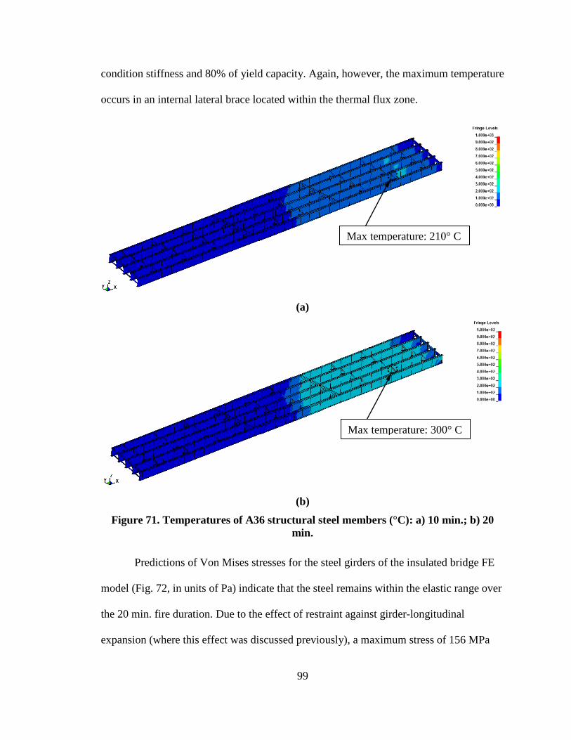
99
condition stiffness and 80% of yield capacity. Again, however, the maximum temperature
occurs in an internal lateral brace located within the thermal flux zone.
(a)
(b)
Figure 71. Temperatures of A36 structural steel members (°C): a) 10 min.; b) 20 min.
Predictions of Von Mises stresses for the steel girders of the insulated bridge FE
model (Fig. 72, in units of Pa) indicate that the steel remains within the elastic range over
the 20 min. fire duration. Due to the effect of restraint against girder-longitudinal
expansion (where this effect was discussed previously), a maximum stress of 156 MPa
Max temperature: 210° C
Max temperature: 300° C
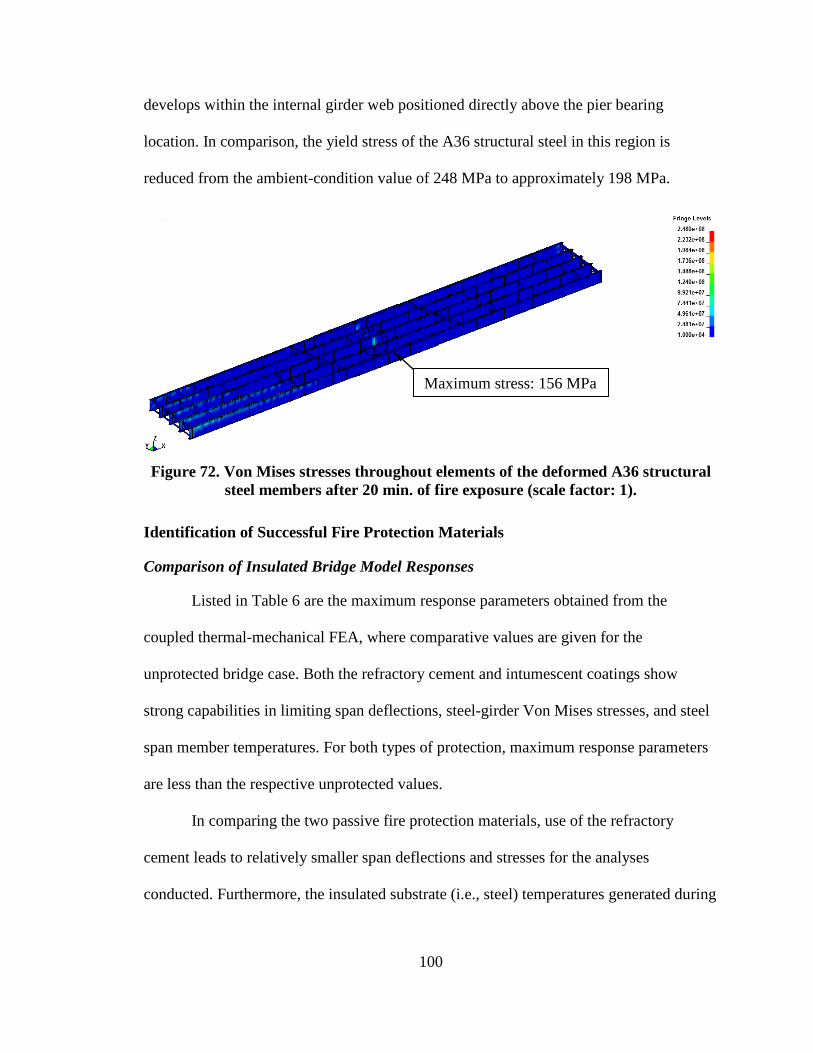
100
develops within the internal girder web positioned directly above the pier bearing
location. In comparison, the yield stress of the A36 structural steel in this region is
reduced from the ambient-condition value of 248 MPa to approximately 198 MPa.
Figure 72. Von Mises stresses throughout elements of the deformed A36 structural
steel members after 20 min. of fire exposure (scale factor: 1).
Identification of Successful Fire Protection Materials
Comparison of Insulated Bridge Model Responses
Listed in Table 6 are the maximum response parameters obtained from the
coupled thermal-mechanical FEA, where comparative values are given for the
unprotected bridge case. Both the refractory cement and intumescent coatings show
strong capabilities in limiting span deflections, steel-girder Von Mises stresses, and steel
span member temperatures. For both types of protection, maximum response parameters
are less than the respective unprotected values.
In comparing the two passive fire protection materials, use of the refractory
cement leads to relatively smaller span deflections and stresses for the analyses
conducted. Furthermore, the insulated substrate (i.e., steel) temperatures generated during
Maximum stress: 156 MPa
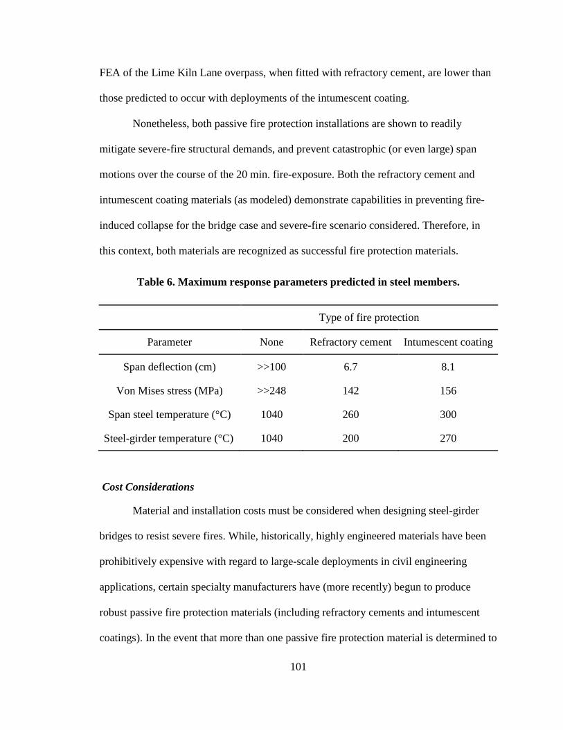
101
FEA of the Lime Kiln Lane overpass, when fitted with refractory cement, are lower than
those predicted to occur with deployments of the intumescent coating.
Nonetheless, both passive fire protection installations are shown to readily
mitigate severe-fire structural demands, and prevent catastrophic (or even large) span
motions over the course of the 20 min. fire-exposure. Both the refractory cement and
intumescent coating materials (as modeled) demonstrate capabilities in preventing fire-
induced collapse for the bridge case and severe-fire scenario considered. Therefore, in
this context, both materials are recognized as successful fire protection materials.
Table 6. Maximum response parameters predicted in steel members.
Type of fire protection
Parameter None Refractory cement Intumescent coating
Span deflection (cm) >>100 6.7 8.1
Von Mises stress (MPa) >>248 142 156
Span steel temperature (°C) 1040 260 300
Steel-girder temperature (°C) 1040 200 270
Cost Considerations
Material and installation costs must be considered when designing steel-girder
bridges to resist severe fires. While, historically, highly engineered materials have been
prohibitively expensive with regard to large-scale deployments in civil engineering
applications, certain specialty manufacturers have (more recently) begun to produce
robust passive fire protection materials (including refractory cements and intumescent
coatings). In the event that more than one passive fire protection material is determined to

102
be suitable in preventing fire-induced, catastrophic failure for a bridge of interest, then
the summation of material costs, installation costs, and maintenance costs should be
factored into the selection process.
With respect to installation costs, it should be noted that the refractory cement
material is typically spray-applied over a small-gage welded wire fabric. In order to
install the refractory cement to the multitudinous cross-bracing members along the
underside of the Lime Kiln Lane overpass, a considerable amount of labor would be
required to properly cut and fit (or bend) the welded wire meshes to the multiply
contoured bracing surfaces. In contrast, as an advantage in this scenario, the intumescent
coating can be spray applied to directly adhere to the surface of an arbitrarily shaped
cross-section.

103
SUMMARY AND CONCLUSIONS
This study was motivated by the DHS/IP capability gap statement, wherein it is
recognized that new materials and applications are needed to mitigate and prevent
structural damage that can be caused to civil infrastructure by severe fires. Accordingly,
this study furthers the development of new fire protection applications in infrastructure
systems. The scope of the investigation centers on the development of new applications
in passive fire protection materials within the context of shielding steel-girder bridges
against severe fire effects.
Potential, new applications are assessed by carrying out coupled thermal-
mechanical finite element analyses, where bridge finite element models are modeled with
the protection systems and subjected to mechanical and thermal loading consistent with
severe-fire conditions. Comparative assessments of the bridge response-quantities, as
calculated during the finite element analyses, are used to identify successful applications
of passive fire protection materials.
As part of this study, an extensive literature review was carried out to ascertain
the state of the art in fire protection of steel-girder bridges. Based on the available
literature, key factors on the impact of severe fires have been identified. Further, the
literature review has facilitated the identification of specific research needs areas that
need to be explored in order to enhance steel-girder bridge resistance to severe fires
throughout the US infrastructure.
As identified during the literature review, a small number of survey studies have
been previously completed, where the study interests centered around identifying the
104
common causes of bridge collapse. Furthermore, these studies have assessed the rates of
bridge collapse for a given hazard type. It has been consistently found that bridges in the
US are severely damaged or suffer collapse from fires at significant rates, even when
compared to other prevalent hazards such as earthquakes.
A review of forensic findings from recent fire-induced collapses of steel-girder
bridges within the US has revealed that gasoline tank truck fires (within the vicinity of
bridges) constitute a worst-case scenario in the consideration of fire effects on bridges.
During severe fires that develop from the ignition of large, concentrated volumes of
gasoline (i.e., gasoline tank truck fires), temperatures can reach and exceed 1000° C
within minutes of ignition. Further, steel-girder bridges exposed to these severe-fire
conditions, where large portions of a given span can become engulfed in flames, tend to
collapse within approximately 20 min. Such rapid collapses are perpetuated by the
general lack of installed fire protection systems on US bridges.
Due to the wide variety of bridge geometric layouts, clearance heights,
interchanges, and traffic rates, extreme variability is found among the levels of exposure
and risk faced by the structural members of a given bridge. However, no standards or
methodology currently exists for assessing the level of severe-fire risk faced by a given
bridge. More generally, the tentative standard portions that do pertain to fire safety design
for bridges are extremely limited. Extant bridge fire protection standards offer neither
prescriptive nor performance-based provisions, but rather, consist of a nominal statement
of the need to protect bridges from temperature exposures that can weaken or collapse the
affected structure. Consequently, no standardized means exist for selecting, designing,
105
and deploying bridge fire protection systems and materials. Furthermore, no standardized
fire-safety analysis techniques have been established.
A steel-girder bridge has been selected for study, and a high resolution finite
element model has been formed based on the corresponding bridge structural drawings.
Drawing from the literature, temperature-dependent structural material properties and
thermal properties have been synthesized and incorporated into the model. Additionally,
a representative fire scenario has been formed based on a recent fire incident that
occurred at the selected bridge. The severe-fire scenario incorporates the characteristics
of a fully loaded gasoline tank truck fire. Based on the literature, a means of
incorporating the severe fire into the finite element model (as thermal loading) has been
identified and enacted.
Common types of passive fire protection materials have been surveyed, and two
types of material have been taken into consideration in the current study. Namely,
refractory cements and intumescent coatings have been identified as having potential in
passive fire protection applications for protecting the multiply contoured members
germane to steel-girder bridge spans. Corresponding sets of mechanical and thermal
material properties have been obtained from material manufacturers for each of the
refractory cement and intumescent coating materials.
A series of coupled thermal-mechanical finite element analyses have been carried
out, where (as a control measure) the unprotected steel-girder bridge has been subjected
to gravity loading and thermal loads associated with the representative severe-fire
scenario over a simulated period of 20 min. An additional finite element simulation has
been carried out, where the steel-girder bridge model has been fitted with refractory
106
cement material to insulate the underside of the bridge spans. A separate, final coupled
thermal-mechanical finite element simulation has been completed where the steel-girder
bridge model has been fitted with the intumescent coating material.
Based on the finite element simulation results, both the refractory cement and the
intumescent coating materials have demonstrated capabilities in limiting span deflections,
maintaining steel-member stresses to acceptably low (i.e., below-yield) levels. Further,
both materials have demonstrated the ability to insulate the structural materials so as to
generally limit the buildup of temperatures to levels that cause severe structural material
degradation. Accordingly, with the caveat of taking material and installation costs into
account, both the refractory cement and intumescent coating have been identified as
successful passive fire protection materials for the fire scenario and bridge case
considered.
Future Research
The following items have been recognized as requiring further study:
• Physical testing of structural assemblies is needed to facilitate validation the full-bridge finite element simulations.
• The use of computational fluid dynamics should be incorporated into the analytical framework so that the effects of wind, and fire source propagation can be taken into account.
• The effect of variations in bridge layout, soil-structure interaction, relative positioning between the bridge and the fuel source, and fire duration should all be explored as part of future analytical efforts.
107
REFERENCES
Albi (2012). “Albi Clad 800 Product Data Information.” Albi Manufacturing. East Berlin, Connecticut.
American Concrete Institute (ACI). (2011). Building Code Requirements for Structural Concrete and Commentary. ACI 318-11, Farmington Hills, Michigan.
ACI. (1994). Guide for Determining the Fire Endurance of Concrete Elements. ACI Report 216R1-48.
Astaneh-Asl, A., Noble, C. R., Son, J., Wemhoff, A. P., Thomas, M. P., and McMichael, L. D. (2009). “Fire Protection of Steel Bridges and the Case of the MacArthur Maze Fire Collapse.” TCLEE 2009: Lifeline Earthquake Engineering in a MultiHazard Environment, Oakland, CA, June 28th-July 1st, 2009.
ASTM. (2001). “Standard Test Methods for Determining Effects of Large hydrocarbon Pool fires on Structural Members and Assemblies, ASTM E1529.” ASTM, West Conshohocken, Pa.
Babrauskas, V. and Peacock. R. D. (1992). “Heat Release Rate: The Single Most Important Variable in Fire Hazard.” Fire Safety Journal, 18, 255-272.
Bartholmai, M., Schriever, R., and Schartel, B. (2003). “Influence of External Heat Flux and Coating Thickness on the Thermal Insulatino Properties of Two Different Intumescent Coatings Using Cone Calorimeter and Numerical Analysis.” Fire and Materials. Vol. 27, 151-162.
Beard, A., and Carvel, R. (2005). “The Handbook of Tunnel Fire Safety.” Thomas Telford Press, London.
Bergmeister, K. (2008). “Real Scale Tunnel Fire Tests Virgl/Virgolo tunnel; Bozen/Bolzano- Italy.” Workpackage 6 Fire effects and tunnel performance: system response D62, UPTUN.
Boström, L. and Larsen, C.K. (2006), “Concrete for Tunnel Linings Exposed to Severe Fire Exposure”, Fire Technology, Vol. 42, pp. 351-362.
Brekelmans, J., and Bosch, R. (2003). “Large Scale Tunnel Fire Test Runehamar.” Workpackage 2 Fire development and mitigation measures D213, UPTUN.
Choi, J. (2008). “Concurrent Fire Dynamics Models and Thermomechanical Analysis of Steel and Concrete Structures.” Doctoral dissertation, Georgia Institute of Technology, Atlanta, Georgia.
108
Colombo, M. (2011). “Tanker Truck Carrying Septic Tank Waste Catches Fire on I-71 N.” WHAS11, <http://www.whas11.com/home/Semi-truck-catches-fire-on-I-71-N-123395278.html>, last accessed on Nov. 7, 2012.
Consolazio, G. R., Davidson, M. T., and Getter, D. J. (2010). “Vessel crushing and structural collapse relationships for bridge design.” Structures Research Report No. 72908/74039, Engineering and Industrial Experiment Station (EIES), University of Florida (UF), Gainesville, Florida.
Davidson, M. T., Harik, I. E., and Davis, B. (2012). “Impact of Fire and Passive Fire Protection of Infrastructure: State of the Art.” ASCE Journal of Performance of Constructed Facilities, in press.
Dunn, D. S., and Chowdhury, A. H. (2009). “Analysis of Structural Materials Exposed to a Severe Fire Environment.” United States Nuclear Regulatory Commission (USNRC), Report NUREG/CR-6987, Washington , D.C.
ENV. (1995a). Eurocode 2: Design of Concrete Structures – Part 1-2: Fire Resistance, 1992-1-2 European Pre-Standard.
ENV. (1995b). Eurocode 3: Design of Steel Structures – Part 1-2: Fire Resistance, 1993-1-2 European Pre-Standard.
Federal Emergency Management Agency (FEMA). (2002). “World Trade Center Building Performance Study: Data Collection, Preliminary Observations, and Recommendations.” Federal Insurance and Mitigation Administration, Washington, D.C.
Federal Highway Administration (FHWA). (2007). Evaluation of LS-DYNA Concrete Material Model 159. FHWA-HRT-05-063.
FHWA. (1999). Truck Characteristics Analysis. FHWA, Washington, D.C.
Galambos, T. V., Leon, R. T., French, C. W., Barker, M. and Dishongh, B. (1993). “Inelastic Rating Procedures for Steel Beam and Girder Bridges.” NCHRP report 352, Washington , D.C.
Ham, D. B., and Lockwood. (2002). “National Needs Assessment for Ensuring Transportation Infrastructure Security.” American Association of State Highway and Transportation Officials (AASHTO), Washington, D.C.
Harik, I. E., Shaaban, A. M., Gesund, H., Valli, G. Y., and Wang, S. T. (1990). “United States Bridge Failures, 1951-1988.” Journal of Performance of Constructed Facilities, 4(4), Paper No. 25181.
Hurley, M. J., and Bukowski, R. W. (2008). “Fire Protection Handbook, 20th Edition. Volume 1. Chapter 7.” National Fire Protection Association (NFPA), Quincy, Massachusetts.
109
Ingason, H. (2006). “Design Fires in Tunnels.” Safe & Reliable Tunnels: Innovative European Achievements, Second International Symposium, Lausanne, Switzerland.
Kodur, V. K., Gu, L., and Garlock, M. E. (2010). “Review and Assessment of Fire Hazard in Bridges.” Transportation Research Record 2172, TRB, Washington, D.C., 23-29.
Kodur, V. K., Garlock, M. E., and Iwankiw, N. (2007). “National Workshop on Structures in Fire: State-of-the-Art, Research and Training Needs.” Report CEE-RR – 2007/03, National Institute of Standards and Technology (NIST), U.S. Department of Commerce, East Lansing, MI.
LSTC. (2012). LS-DYNA Keyword User’s Manual Volume II Material Models, Livermore Software Technology Corporation (LSTC), Livermore, California.
LSTC. (2011). LS-DYNA Keyword User’s Manual Volume I, LSTC, Livermore, California.
Morgan-Thermal Ceramics. (2004). “FireMaster® FireBarrier 110 TM / FireBarrier 135TM: Product Information.” Augusta, Georgia.
National Cooperative Highway Research Program (NCHRP). (2011). Design Fires in Road Tunnels. NCHRP Synthesis 415, Washington, D. C.
National Fire Protection Association (NFPA). (2011). “NFPA 502: Standard for Road Tunnels, Bridges, and Other Limited Access Highways: 2011 Edition.” Quincy, MA.
National Institute of Standards and Technology (NIST). (2005). Mechanical Properties of Structural Steels. NIST NCSTAR 1-3D, Washington, D.C.
NIST. (2000). Thermal Radiation from Large Pool Fires. NISTIR 6546, Washington, D. C.
Naus, D.J. (2006). “The Effect of Elevated Temperature on Concrete Materials and Structures – A Literature Review.” US Nuclear Regulatory Commission Report NUREG/CR-6900, Oak Ridge National Laboratory Report ORNL/TM-2005/553, Washington, D.C.
Olst, D., and Bosch, R. (2003). “Protecting the Runehamar Tunnel in Norway with Promatect®-T Against Multiple Fires, as Part of the UPTUN Research Programme, PROMAT BV.” International Seminar on ‘Catastrophic Tunnel Fires’, Paper 9, Borås, Sweden.
Payá-Zaforteza, I., and Garlock, M. E. (2010). “A 3D Numerical Analysis of a Typical Steel Highway Overpass Bridge Under a Hydrocarbon Fire.” Structures in Fire, Proceedings of the Sixth International Conference, 11-18.
110
Precast/Prestress Concrete Institute (PCI). (2010). “PCI Design Handbook: Precast and Prestressed Concrete, 7th Edition.” PCI, Chicago, Illinois.
Promat International. (2005). “Tunnel Fire Protection: A conversion from NFPA 502 standard to practical systems and tested solutions.” Promat International NV, Tisselt, Belgium.
Research and Innovative Technology Administration (RITA). (2006). “The Nation’s Freight.” U.S. Department of Transportation, Washington D.C.
Roberts, J.E., Kulicki, J.M., and Beranek, D.A. (2003). “Recommendations for Bridge and Tunnel Security.” Report FHWA-IF-03-036. (FHWA)/AASHTO Blue Ribbon Panel.
Sakumoto, Y., Nagata, J., Kodaira, A., and Saito, Y. (2001). “Durability Evaluation of Intumescent Coating for Steel Frames.” Journal of Materials in Civil Engineering, 13(4), 274-281.
Stoddard, R. (2004). “Inspection and Repair of a Fire Damaged Prestressed Girder Bridge.” Report IBC-04-17, Washington State DOT, Olympia, WA.
Wardhana, K., and Hadipriono, F. C. (2003). “Analysis of Recent Bridge Failures in the United States.” Journal of Performance of Constructed Facilities, 17(3), 144-150.
Zenonas, K. (2007). “Structural Design of Polymer Protective Coatings for Reinforced Concrete Structure. Part II: Experimental Verification.” Journal of Civil Engineering and Management, ISSN: 1392-3730.