Embed Size (px)
Citation preview
Assessment of Passive Fire Protection in Seveso Facilities
Prepared for
LECBrandweerBRZO
By
High14 Technologies Ltd
Project Details
H14T Project Number: H14T-2018-006
H14T Document Number: H14T-2018-006-R-01
Client: LECBrandweerBRZO
Client Contact: Jan Meinster
Prepared by: Simon Thurlbeck
Email: [email protected]
Telephone: +44 7885 651021
Revision Record
Revision No. Date: Comments:
0 25th August 2018 First Issue for Client Review – Requires additional references and figures
1 11th October 2018 Including updates as discussed with Client.
Assessment of Passive Fire Protection in Seveso Facilities H14T Document No: H14T-2018-006-R-01 Rev 1
1 of 4
Contents 1 Introduction ...................................................................................................................................... 1
1.1 Purpose ...................................................................................................................................... 1
1.2 Definition of PFP ........................................................................................................................ 1
1.3 Exclusions ................................................................................................................................... 1
1.4 The Contents of this Document ................................................................................................. 1
2 Mitigating Fire Risks in Seveso Establishments Using PFP.............................................................. 2
2.1 Major Hazards Risks on Industrial Establishments .................................................................... 2
2.2 The Role of PFP .......................................................................................................................... 2
2.3 Key Steps for the Use of PFP on Seveso Establishments ........................................................... 3
3 Fire Hazards in Seveso Facilities ...................................................................................................... 4
3.1 Introduction ............................................................................................................................... 4
3.2 Fire Hazard Characteristics ........................................................................................................ 4
3.2.1 CELLULOSIC FIRES ............................................................................................................................ 4 3.2.2 POOL FIRES .................................................................................................................................... 5 3.2.3 JET FIRES ........................................................................................................................................ 5 3.2.4 OTHER FIRE HAZARDS AND PFP ......................................................................................................... 6 3.2.5 COMBINED FIRE SCENARIOS .............................................................................................................. 6 4 Mitigating Fire Risks in a Seveso Establishment Using PFP ............................................................ 8
4.1 Defining a PFP Scheme - Codes and Standards and Methods ................................................... 8
4.2 Interaction of PFP with Other Fire Mitigation Measures........................................................... 9
4.3 Items that are Typically Protected Using PFP in Seveso Establishments ................................. 10
4.3.1 STRUCTURAL STEELWORK ............................................................................................................... 10 4.3.2 BARRIERS ..................................................................................................................................... 11 4.3.3 HIGH PRESSURE CONTAINMENTS (E.G. PROCESS VESSELS, REACTORS, PRESSURISED GAS STORAGE) ............. 11 4.3.4 LOW-PRESSURE CONTAINMENTS (TANKS, SILOS, HOPPERS, ETC) ............................................................ 12 4.3.5 PIPEWORK (PROCESS, DEPRESSURISATION AND DELIVERY) .................................................................... 12 4.3.6 VESSEL AND PIPE SUPPORTS ............................................................................................................ 12 4.3.7 FLANGES ...................................................................................................................................... 13 4.3.8 VALVES AND ACTUATORS ................................................................................................................ 13 4.3.9 CRITICAL CABLING AND CONTROL LINES ............................................................................................. 14 4.3.10 COMMENTARY ON BUILDINGS ....................................................................................................... 14
4.4 Checklist Related to Areas that MAY Need PFP ....................................................................... 15
5 PFP Systems Used in Seveso Establishments ................................................................................ 17
5.1 Passive Fire Protection Coatings: ............................................................................................. 17
5.2 Dry-Fit Systems ........................................................................................................................ 18
5.3 Wet-Applied PFP Systems ........................................................................................................ 18
5.4 Barrier Systems ........................................................................................................................ 19
5.5 Penetrations Through Barrier Systems .................................................................................... 20
5.6 Typical Uses .............................................................................................................................. 21
Assessment of Passive Fire Protection in Seveso Facilities H14T Document No: H14T-2018-006-R-01 Rev 1
2 of 4
6 Defining PFP Performance ............................................................................................................. 23
6.1 The Importance of Assessing Suitability .................................................................................. 23
6.2 Factors to Specify how PFP Should Perform During a Fire ...................................................... 23
6.3 Communicating Performance .................................................................................................. 23
6.3.1 FIRE RATING OF BARRIERS, FIRE DIVISIONS AND PARTITIONS ................................................................ 24 6.3.2 FIRE RATING OF PENETRATIONS ....................................................................................................... 25 6.3.3 FIRE RATING OF STRUCTURES, EQUIPMENT AND PLANT ....................................................................... 25
6.4 Other Factors that Can Affect PFP Performance ..................................................................... 25
6.5 Performance Demonstration ................................................................................................... 27
6.5.1 KEY ORGANISATIONS IN PFP PERFORMANCE DEMONSTRATION ............................................................ 27 6.5.2 PROCESSES FOR DEMONSTRATING PERFORMANCE .............................................................................. 28 6.5.3 TEST STANDARDS .......................................................................................................................... 30
6.6 Evaluating Whether a PFP System has been Implemented Correctly ..................................... 31
7 Damage to PFP Systems ................................................................................................................. 32
7.1 The Causes of Damage ............................................................................................................. 32
7.2 Dense Concrete ........................................................................................................................ 32
7.3 Lightweight Cementitious (LWC) PFP ...................................................................................... 33
7.4 Epoxy (intumescent & subliming) PFP ..................................................................................... 35
7.5 Insulation Material Performance ............................................................................................. 38
7.6 Dry-Fit Systems ........................................................................................................................ 40
7.6.1 DAMAGE TO OUTER LAYER MATERIAL .............................................................................................. 40 7.6.2 INTERNAL INSULATION MATERIAL DAMAGE ....................................................................................... 41 7.6.3 FIXING OR RETENTION SYSTEM DAMAGE ........................................................................................... 41 7.6.4 JOINT OR SEAL DAMAGE ................................................................................................................. 42 7.6.5 DAMAGE AT THE INTERFACE BETWEEN THE DRY-FIT SYSTEM AND ANOTHER SYSTEM .................................. 43 7.6.6 FAILURE TO REPLACE ANY OF THE COMPONENTS FOLLOWING REMOVAL. ................................................. 44 7.6.7 SUMMARY OF TYPICAL DAMAGE FOR DRY-FIT SYSTEMS ....................................................................... 44
7.7 Wet Applied System Damage Mechanisms ............................................................................. 45
7.8 Barrier Damage Mechanisms ................................................................................................... 45
7.9 Penetration Damage Mechanisms ........................................................................................... 47
7.9.1 CERTIFIED PIPE PENETRATION SEALS ................................................................................................. 47 7.9.2 NON-CERTIFIED PENETRATION DESIGNS ............................................................................................ 47 7.9.3 CABLE TRANSIT DAMAGE ................................................................................................................ 48 7.9.4 DAMAGE TO DOORS AND WINDOW ................................................................................................. 49 7.9.5 DAMAGE TO DUCTS ....................................................................................................................... 49 8 Detailing of PFP Coating Systems .................................................................................................. 51
8.1 The Importance of Correct Detailing ....................................................................................... 51
8.2 Hollow-Filled Boxed Section Detailing ..................................................................................... 51
8.3 Termination Details .................................................................................................................. 52
8.4 Interfaces with Coatings .......................................................................................................... 53
8.5 Lack of Loadpath Protection .................................................................................................... 54
Assessment of Passive Fire Protection in Seveso Facilities H14T Document No: H14T-2018-006-R-01 Rev 1
3 of 4
8.6 3-sided Protection .................................................................................................................... 55
8.7 Coatbacks ................................................................................................................................. 55
8.8 Standing water ......................................................................................................................... 57
8.9 Cut-outs.................................................................................................................................... 58
9 Integrity Management – Inspection and Assessment................................................................... 59
9.1 Integrity Management Process ................................................................................................ 59
9.2 Roles and Responsibilities ........................................................................................................ 59
9.3 Processes and Procedures ....................................................................................................... 59
9.4 Note on Documentation and Record Keeping ......................................................................... 60
9.5 Note on Inspection of PFP Systems ......................................................................................... 60
9.6 Note on Assessment of PFP Systems Following Inspection ..................................................... 61
10 Integrity Management – Repairs to PFP Systems ....................................................................... 62
10.1 General Requirements for PFP System Repair....................................................................... 62
10.2 Types of Repair ...................................................................................................................... 62
10.3 Temporary Repairs ................................................................................................................. 63
10.4 Repair Monitoring .................................................................................................................. 63
10.5 Notes on Repair of Coatings .................................................................................................. 63
10.6 Notes on Repairs to Dry-fit systems ...................................................................................... 64
10.7 Notes on Repairs to Wet-Applied Systems ............................................................................ 65
10.8 Notes on Repairs to Barriers Systems .................................................................................... 65
10.9 Notes on Repairs of Penetrations through Barriers .............................................................. 65
11 Assessing Ageing PFP on Seveso Establishments ........................................................................ 67
11.1 The Assessment Process ........................................................................................................ 67
11.2 Checklist 1 – Documentation Review .................................................................................... 67
11.3 Checklist 2 – A Design and Specification Review ................................................................... 67
11.4 Checklist 3 – A Review that the Integrity of the PFP System Being Managed Correctly ....... 68
Appendix A: PFP and SEVESO III Directive ........................................................................................... 1
The Seveso Directive ........................................................................................................................... 2
Article 8: MAPP ................................................................................................................................... 2
Article 10: Safety Report ..................................................................................................................... 3
Article 11: Modification ...................................................................................................................... 3
Article 20: Inspections ......................................................................................................................... 3
Appendix B: ASSESSMENT Checklists ................................................................................................... 5
Checklist 1 – Documentation Review ................................................................................................. 6
Checklist 2 - Has the PFP System Under Assessment Been Designed and Specified Correctly? ........ 8
Checklist 3 - Is the Integrity of the PFP System Being Managed Correctly? ....................................... 9

Assessment of Passive Fire Protection in Seveso Facilities H14T Document No: H14T-2018-006-R-01 Rev 1
4 of 4
Appendix C: PFP Damage Assessment Tables.................................................................................... 10
Appendix Table-C1: Coating System Damage Levels ........................................................................ 11
Appendix Table-C2: Dry-Fit System Damage Levels ......................................................................... 15
Appendix Table-C3: Wet Applied System Damage Levels ................................................................ 16
Appendix Table-C4: Wet Applied System Damage Levels ................................................................ 17
Appendix Table-C5: Penetration System Damage Levels ................................................................. 18
Assessment of Passive Fire Protection in Seveso Facilities H14T Document No: H14T-2018-006-R-01 Rev 1
5 of 4
Abbreviations
Abbreviation Description
A (or CF) Denotes a Cellulosic Fire
ABS American Bureau of Shipping
AES Alkali Earth Silicate
AFP Active Fire Protection
API American Petroleum Institute
ASTM American Society of Testing and Materials
BAM German Federal Institute for Materials Research and Testing
BS British Standard
CCPS Center for Chemical Process Safety
CCT Critical Core Temperature
CUF Corrosion Under Fireproofing
CUI Corrosion Under Insulation
DNV Det Norske Veritas
E Integrity (Requirement of a Fire Division or Partition)
EDP Emergency Depressurisation
EER Escape, Evacuation and Rescue
ER Emergency Response
ESD Emergency Shutdown
ESDV Emergency Shutdown Valve
FABIG Fire and Blast Information Group
F&G Fire and Gas
FRP Fibre Reinforced Plastic
GRP Glass Reinforced Plastic
H (or HF) Denotes a Hydrocarbon Pool Fire
HVAC Heating Ventilation and Air Conditioning
I Insulation (requirement of a Fire Division or Partition)
ISO International Standards Organisation
J (or JF) Denotes a Jet Fire
LNG Liquified Natural Gas
LPG Liquified Petroleum Gas
LTB Lateral Torsional Buckling
LWC Lightweight Cementitious
MAPP Major Accident Prevention Plan
MCA Maritime and Coastguard Agency
MCC Motor Control Centres
MMMF Man Made Mineral Fibre
NFPA National Fire Protection Association
PFP Passive Fire Protection
PSV Pressure Safety Valve
R Stability (Requirement of a Fire Division or Partition)
SMS Safety Management System
UL Underwriters Laboratories
UPS Uninterruptible Power Supplies
UV Ultraviolet
Assessment of Passive Fire Protection in Seveso Facilities H14T Document No: H14T-2018-006-R-01 Rev 1
Page 1 of 62
1 Introduction
1.1 Purpose This document has been prepared by LEC BrandweerBRZO to support the inspection theme of ageing
Passive Fire Protection (PFP) at Seveso companies.
The Seveso III Directive contains Articles that relate to the management of major accident scenarios
such as fire and, in particular, the use of mitigation measures such as Passive Fire Protection (PFP) to
limit risks to humans and the environment. The purpose of this document is to provide a suitable level
of information regarding PFP, along with checklists, that will enable an Industrial Safety Inspector to
visit an Upper or Lower Level Seveso establishment, evaluate whether the PFP installed on the
establishment to mitigate residual fire risks is fit-for-purpose, and confirm that the PFP meets the
requirements of the relevant Articles. PFP and the Seveso Articles is discussed in Appendix A.
Because the inspection process is periodic, the primary concerns for inspectors are understanding how
the PFP systems can be damaged with time and ensuring that the PFP systems that are documented
still perform as expected.
However it is also important to understand what role the PFP has been designed to play in major
accident hazard mitigation and emergency response for a particular establishment, how its need was
identified, whether the systems that are installed are appropriate for the environment and hazards
that they will be exposed to, and whether systems and processes are in place to assure the ongoing
integrity of the PFP.
Ultimately the document will assist the Inspectors in evaluating whether the responsibilities placed
upon the operator of the establishment by the Articles of Seveso III Directive have been satisfied with
respect to PFP.
1.2 Definition of PFP Passive Fire Protection (or PFP) is a coating, cladding or free-standing system that provides thermal
protection to a substrate or protected area in the event of fire. The protection that is provided by a
PFP system that gives insulation, reducing the rate at which heat is transmitted to the substrate below,
along with the ability to provide mechanical integrity against any loads introduced by the fire event,
be they directly from the fire such as erosion, or introduced by the strains induced by thermal
expansion.
Being passive, PFP doesn’t require manual, mechanical, or other means to start it and once working it
doesn’t need a source of material to keep it working.
1.3 Exclusions This document considers only the use of PFP on fixed structures, plant and equipment items that are located on Seveso establishments. It does not consider the situation where PFP is used for the transport of hazardous substances, such as Liquified Petroleum Gas (LPG), Liquified Natural Gas (LNG), bulk chemicals, etc.
1.4 The Contents of this Document This document provides guidance on evaluating ageing PFP in hazardous establishments during inspections by safety inspectors in support of the Seveso III Directive to establish whether the installed PFP will mitigate the fire hazards as defined in the Major Accident Prevention Policy (MAPP), Safety Management System (SMS) and any supporting documentation such as the Safety Reports. It provides
Assessment of Passive Fire Protection in Seveso Facilities H14T Document No: H14T-2018-006-R-01 Rev 1
Page 2 of 62
checklist questions for inspectors and provides supporting information that will assist in the inspector’s assessment process, including how the questions are related to the Seveso III Directive.
2 Mitigating Fire Risks in Seveso Establishments Using PFP
2.1 Major Hazards Risks on Industrial Establishments
Producing, processing and storing flammable inventories on industrial establishments is hazardous,
and can lead to major fires that could be harmful to human health, the environment, and to
businesses. The operators of an establishment can utilise a range of measures to minimise the risk of
such events from occurring. Relevant design codes and standards should have been, and can be,
applied for both new designs and modifications to existing installation. Additionally, the adoption of
inherently safer design principles can help to prevent and mitigate fires and explosions by such factors
as:
Leak source minimisation
Flammable inventory minimisation
Process design simplification
Substitution of flammable materials
Ignition prevention.
However, it is recognised that there is always residual potential for fire events to occur and therefore
appropriate protection will be required to certain structures and items of equipment to manage any
residual risks. PFP is one such mitigation measure which used in industrial establishments.
When considering inherently safer principles, then prevention of a fire is preferential to protection
against a fire. However, if there is still residual risk that is unacceptable and requires mitigation, then
a passive system is preferred to an active system.
2.2 The Role of PFP
PFP measures will not prevent a fire from starting and will not prevent the immediate consequences
of those events to personnel, equipment or structures who are directly exposed to the fire (unless the
PFP is a barrier and provides shielding). PFP measures are primarily of benefit to reduce the risk of an
event that may escalate to cause further damage or put more personnel at risk of harm. PFP can be
installed for the purposes of life safety, protection of environment, or for commercial/business
reasons.
PFP is a mitigation measure intended to prevent or minimize the thermal effects of the fire by
controlling the rate at which thermal energy is transferred to the protected structure or equipment,
thereby limiting the potential for escalation due to thermally induced failure.
In general, PFP materials do not provide protection against explosion, however, to perform as a fire
protection measure they may need to survive an accompanying explosion.
The primary benefits of PFP are realised in the very early stages of a fire when efforts are primarily
directed at shutting down processes, isolating fuel supplies to the fire, depressurising inventories,
performing emergency response, mustering and conducting personnel evacuation. If supporting
structures, critical enclosures and safety critical equipment are not protected, they could fail during
this initial period and the control of fire effects and effective escape, evacuation and emergency
response may be compromised.
Assessment of Passive Fire Protection in Seveso Facilities H14T Document No: H14T-2018-006-R-01 Rev 1
Page 3 of 62
2.3 Key Steps for the Use of PFP on Seveso Establishments
The key elements that define the use of PFP on any establishment are:
A determination of whether the establishment is a Seveso establishment, and what level of
establishment it is, based on the hazardous materials on the establishment.
The application of a risk assessment process that considers potential major accident scenarios
and the consequences of those scenarios, both onsite and offsite, to human health and the
environment.
The development of a fire protection strategy to mitigate to those risks, and which could
include PFP.
The identification of the required performance of any PFP systems.
The correct selection and implementation of PFP systems to provide the performance.
The inspection and maintenance to ensure that the performance is maintained.
The clear documentation of all the above.
Assessment of Passive Fire Protection in Seveso Facilities H14T Document No: H14T-2018-006-R-01 Rev 1
Page 4 of 62
3 Fire Hazards in Seveso Facilities
3.1 Introduction
Establishments that are identified as Seveso establishments can be wide ranging and will fall under
the following categories:
Bulk chemistry
Trade and distribution
Transshipment and transport
Energy
Fine chemistry
Waste
Petrochemistry
Rubber and Plastic
Others
Where fire hazards are present on any of these Establishments then they will be generated because
of:
Flammable liquids – unrefined or refined hydrocarbon products, or solvents:
Flammable gases – typically hydrocarbon, hydrogen, or synthetic gases.
Flammable spray – a 2-phase combination of flammable liquids and gases.
Flammable solids – in the form of fine chemicals, metals, or cellulosic materials.
With respect to a Seveso classification, a Seveso establishment may not have fire hazards, and hence
no need for PFP, if they do not handle flammable substances as part of their operations. When a
facility does have flammable inventories, and Regulations, codes and standards, risk assessments or
studies have demonstrated that risks can be managed without PFP, then none may be installed.
It is therefore important to recognise that there is no common set of equipment in a Seveso
Establishment which will ALWAYS be protected with PFP.
3.2 Fire Hazard Characteristics
A key element to ensuring adequate performance of PFP is to understand the type of fire that it may be exposed to. A PFP system must be able to mitigate the characteristics of the various types of fire. Failure to ensure this basic requirement can result in the system failing prematurely or not provide the required insulation performance or duration of protection.
For industrial establishments there are 4 predominant types of fires which are mitigated using PFP and these are described in the following sections. There may also be fires that result from the ignition of other, specialised, materials which are briefly discussed.
3.2.1 Cellulosic Fires Cellulosic fires are caused by the burning of cellulosic material such as paper and wood. An impinging cellulosic fire has a lower temperature than a hydrocarbon fire, and it reaches that peak temperature over a longer time interval. The fire is relatively low momentum and does not produce high erosive forces. When a fire of whatever fuel source does not impinge on a structure or equipment item, but still provides a fire loading by thermal radiation only then this is also often considered as a cellulosic fire. Cellulosic fires, or high levels of thermal radiation, should be protected against using a PFP system that has been tested and demonstrated to be effective against this type of fire. The rating of the PFP system to mitigate such a fire will have a designation that contains “A” or “CF”.
Assessment of Passive Fire Protection in Seveso Facilities H14T Document No: H14T-2018-006-R-01 Rev 1
Page 5 of 62
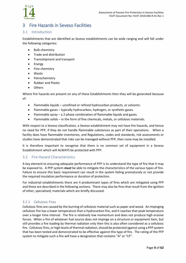
3.2.2 Pool Fires Pool fires are a “turbulent diffusion fire burning above a pool of vaporising liquid fuel where the fuel vapour has zero or very low initial momentum” (Ref: “ISO 13702:1999 Petroleum and natural gas industries -- Control and mitigation of fires and explosions on offshore production installations -- Requirements and guidelines”). Fuels would typically be hydrocarbon based, or solvent based. Heat transfer back from the fire to the pool largely controls the rate of evaporation and hence the fire size and severity. Pool fires can have some turbulence associated with them, and they burn at a higher temperature than cellulosic fires and reach that higher temperature in a much shorter time. The degree of confinement of the fire controls the oxygen supply, causing different levels of heat flux to be generated. Pools fires result from the ignition of any pooled release of a flammable liquid. A pressurised release, or spillage, of a flammable liquid which is not sufficiently atomised or volatile to vaporise and form a jet fire will form a pool fire. Pool fires should be protected against using a PFP system that has been tested and demonstrated to be effective against this type of fire. The rating of the PFP system to mitigate such a fire will have a designation that contains “H” or “HF”. For Seveso Establishments, pool fire scenarios are typically specified in the range of one to four hours duration.
Figure 1– Pool Fire
3.2.3 Jet Fires Jet fires are formed when a high-pressure release of a flammable substance through a hole or crack is ignited. A jet fire is characterised by turbulent diffusion flame resulting from the combustion of a fuel that is continuously released with some significant momentum in a direction or directions, and which makes the fire erosive. They can arise from releases of gaseous, flashing liquid (two phase) and pure liquid inventories. They are typically characterized as high-pressure releases of gas from limited size opening, and the release rate of the gas through a hole to the atmosphere depends on the pressure inside the equipment, the hole size/shape and the molecular weight of the gas. The under or over ventilated conditions of the release can result in different heat flux levels being generated. Jet fires should be protected against using a PFP system that has been tested and demonstrated to be effective
Assessment of Passive Fire Protection in Seveso Facilities H14T Document No: H14T-2018-006-R-01 Rev 1
Page 6 of 62
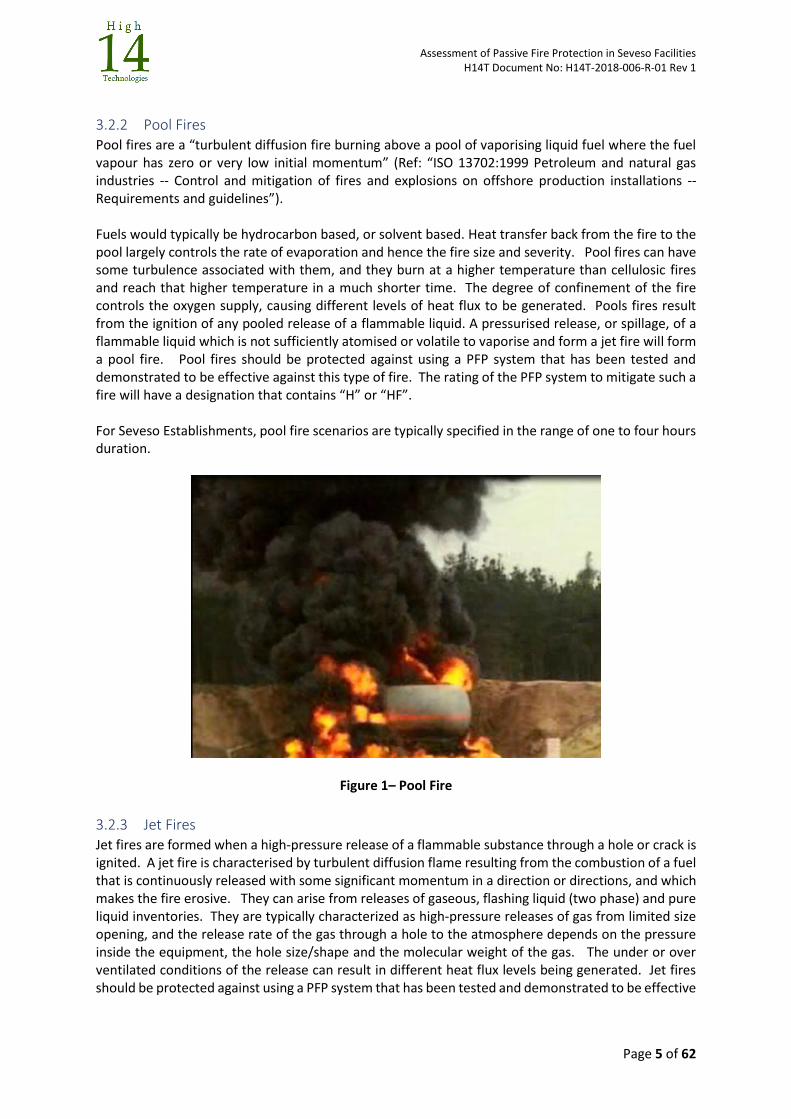
against this type of fire. The rating of the PFP system to mitigate such a fire will have a designation that contains “J” or “JF”. For Seveso Establishments, jet fire scenarios are typically specified with a duration of up to two hours although this is extreme, with one hour being typical.
Figure 2 – A Small Jet Fire
3.2.4 Other Fire Hazards and PFP Other fire hazards found on Seveso establishments may be because of burning powders, chemicals,
or metals. Dependent on the material they may melt and form a liquid, which then burns as a pool
fire, they may undergo pyrolysis and form a gas, which burns above the material as a non-pressurised
fire. In many instances, PFP systems suitable for mitigating cellulosic, pool or jet fires can be used to
mitigate these hazards.
In some instances, traditionally deployed and commercially available PFP is not an appropriate means
of mitigating these fire hazards and cannot be specified. In these situations, a specialised PFP material
may be deployed, or an alternative means of mitigation such as inerting may be the most appropriate
method.
3.2.5 Combined Fire Scenarios It is entirely feasible that a PFP system may be exposed to all types of fires during a fire event. For example:
A high-pressure release of a two-phase liquid may produce a gas jet fire, with associated pool of liquid, that could engulf an equipment item, with areas outside the immediate zone of the fire being exposed to radiative heat loading. As the jet fire decays, the pool fire and radiative component may become dominant. Scenarios of up to 2 hours may be possible for this fire.
Or;
An initial pool fire that escalates to high pressure has jet release because of a subsequent failure.
It is possible to recognise this through the correct specification of the performance requirements, or to adopt a worst-case performance requirement, which identifies the worst fire that could be present and assumes that it lasts for the duration of the scenario.

Assessment of Passive Fire Protection in Seveso Facilities H14T Document No: H14T-2018-006-R-01 Rev 1
Page 7 of 62
Assessment of Passive Fire Protection in Seveso Facilities H14T Document No: H14T-2018-006-R-01 Rev 1
Page 8 of 62
4 Mitigating Fire Risks in a Seveso Establishment Using PFP
4.1 Defining a PFP Scheme - Codes and Standards and Methods
There are several Codes of Practice, standards and guidance documents that can be used to identify
the potential for, and the effects of, fire hazards on Upper and Lower Tier Seveso establishments. The
processes within these resources will identify any risks from fires that can be mitigated using PFP to
reduce risks to human health and the environment. After identifying the risks, resources are also
available to assist in defining how the PFP should be implemented to mitigate those risks. The typical
means for this assessment are:
A Prescriptive Approach: in which a requirement to protect, and the means of protection, is defined
and is based on industry accepted experience and practice. A prescriptive approach can define:
The structures, plant items and equipment that must be protected, including the extent of
protection.
The types and duration of the fires that will be present.
The types of PFP systems that should be used and the means that should be used to test and
demonstrate their performance.
A Risk-Based Approach: in which the operator must identify the hazards and identify those areas of
the establishment that must be protected to manage those hazards to an acceptable level. A risk-
based approach may:
Use upon some of the guidance of a prescriptive approach to help implement the scheme
Result in no PFP being specified if the risks are shown to be acceptable
There are many resources that can be used to produce a PFP scheme. The key to their effectiveness
is in understanding and correctly applying the information and guidance presented. The resources
can be found in:
Internationally recognised Codes of Practice and Standards that describe how to protect
certain types of facilities and certain types of plant items and equipment against fires
Operator company internal guidance documents and standards
Insurance company loss prevention guidelines
Design and EPC internal developed guidance documents and standards
Specialist industry association guidance documents
Publications (Books, conference proceedings, etc)
Some commonly applied guidance (excluding company specific guidance) used in specifying PFP is
contained in Table 1. This list is not extensive.
Assessment of Passive Fire Protection in Seveso Facilities H14T Document No: H14T-2018-006-R-01 Rev 1
Page 9 of 62
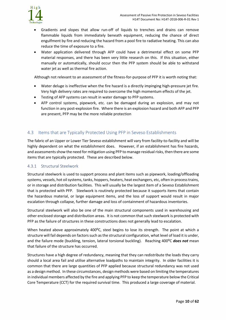
Document Source
API Recommended Practice 2218: Third Edition, July 2013: Fireproofing Practices in Petroleum and Petrochemical Processing Plants
API
API RP 2001 - Fire Protection in Refineries, Ninth Edition API
API 2510A – Fire Protection Considerations for the Design and Operation of Liquefied Petroleum Gas (LPG) Storage Facilities, Second Edition
API
Guidelines for Fire Protection in Chemical, Petrochemical and Hydrocarbon processing Facilities, August 2003
CCPS
Fire Protection Handbook, 20th Edition, 2008 NFPA
Standard for the Fire protection of Storage, NFPA 230. 2003 NFPA
Fire Protection on Chemical Manufacturing Sites. European Guideline CFPA-E No 18:2008
CFPA Europe
Guidance on Passive Fire Protection for Process and Storage Plant and Equipment. 1st Edition, March 2017
Energy Institute
Table 1 – PFP Specification documents
4.2 Interaction of PFP with Other Fire Mitigation Measures The process of major accident scenarios and their management will result in an approach that can
deploy a range of different mitigation measures, other than PFP, to manage fire risks. These include:
Active firefighting protection (AFP), by fixed or mobile means, through the application of
water to cool plant and equipment and extinguish fires.
The containment and redirection of released flammable liquid inventories using bunds,
trenches and drains.
The use of isolation and depressurisation systems to minimise inventory volumes and remove
pressurised inventories.
AFP and PFP are typically integrated as part of an overall fire hazard management strategy, but their
interaction is not straightforward. The following are important points for consideration when
evaluating the fitness-for-purpose of PFP:
Unlike AFP, PFP does not fight fires. It provides insulation that prevents escalation. If
firefighting is required, then PFP is not an effective risk mitigation measure.
Although PFP does not fight fires it can be part of a strategy that allows fire fighters to work
effectively with a facility and any emergency responders should be aware of the role of PFP in
their activities. PFP can influence, and the specification of PFP can be influenced by:
o available access to fight a fire;
o fire-fighting capability of on-site emergency response team;
o the response time of nearest fire brigade;
o the resources available to a fire brigade.
PFP systems cannot prevent flame from reaching other areas of plant (unless installed as a
barrier), nor do they cool adjacent plant and equipment that does not have PFP material
applied (although radiant heat shielding may reduce thermal radiation effects).
The removal of the hazardous inventories in a sufficiently short time before a vessel/pipe
rupture or structural collapse occurs may result in PFP (or AFP) not being required.
Bunds can contain flammable liquids and reduce the chance of adjacent equipment being
directly engulfed, reducing the hazard from a pool fire to radiative heating.
Assessment of Passive Fire Protection in Seveso Facilities H14T Document No: H14T-2018-006-R-01 Rev 1
Page 10 of 62
Gradients and slopes that allow run-off of liquids to trenches and drains can remove
flammable liquids from immediately beneath equipment, reducing the chance of direct
engulfment by fire and reducing the hazard from a pool fire to radiative heating. This can also
reduce the time of exposure to a fire.
Water application delivered through AFP could have a detrimental effect on some PFP
material responses, and there has been very little research on this. If this situation, either
manually or automatically, should occur then the PFP system should be able to withstand
water jet as well as thermal fire action.
Although not relevant to an assessment of the fitness-for-purpose of PFP it is worth noting that:
Water deluge is ineffective when the fire hazard is a directly impinging high-pressure jet fire.
Very high delivery rates are required to overcome the high momentum effects of the jet.
Testing of AFP systems can result in water damage to PFP systems.
AFP control systems, pipework, etc. can be damaged during an explosion, and may not
function in any post-explosion fire. Where there is an explosion hazard and both AFP and PFP
are present, PFP may be the more reliable protection
4.3 Items that are Typically Protected Using PFP in Seveso Establishments
The fabric of an Upper or Lower Tier Seveso establishment will vary from facility-to-facility and will be
highly dependent on what the establishment does. However, if an establishment has fire hazards,
and assessments show the need for mitigation using PFP to manage residual risks, then there are some
items that are typically protected. These are described below.
4.3.1 Structural Steelwork
Structural steelwork is used to support process and plant items such as pipework, loading/offloading
systems, vessels, hot oil systems, tanks, hoppers, heaters, heat exchangers, etc, often in process trains,
or in storage and distribution facilities. This will usually be the largest item of a Seveso Establishment
that is protected with PFP. Steelwork is routinely protected because it supports items that contain
the hazardous material, or large equipment items, and the loss of support would result in major
escalation through collapse, further damage and loss of containment of hazardous inventories.
Structural steelwork will also be one of the main structural components used in warehousing and
other enclosed storage and distribution areas. It is not common that such steelwork is protected with
PFP as the failure of structures in these constructions does not generally lead to escalation.
When heated above approximately 400⁰C, steel begins to lose its strength. The point at which a
structure will fail depends on factors such as the structural configuration, what level of load it is under,
and the failure mode (buckling, tension, lateral torsional buckling). Reaching 400⁰C does not mean
that failure of the structure has occurred.
Structures have a high degree of redundancy, meaning that they can redistribute the loads they carry
should a local area fail and utilise alternative loadpaths to maintain integrity. In older facilities it is
common that there are large quantities of PFP applied because structural redundancy was not used
as a design method. In these circumstances, design methods were based on limiting the temperatures
in individual members affected by the fire and applying PFP to keep the temperature below the Critical
Core Temperature (CCT) for the required survival time. This produced a large coverage of material.
Assessment of Passive Fire Protection in Seveso Facilities H14T Document No: H14T-2018-006-R-01 Rev 1
Page 11 of 62
More recent designs use methods that take advantage of structural redundancy and identify structural
members that are critical to the integrity of the overall structure, and they are protected with PFP.
PFP is not always required if it can be shown that alternative load paths allow for load redistribution
so that the required structural performance is maintained, and escalation does not occur within the
required survival period.
4.3.2 Barriers Barriers provide shielding which could be to:
Prevent direct fire effects on people or plant items through separating a hazardous area from a non-hazardous area. For example, the use of firewalls or radiation shielding to allow personnel to shelter or to escape.
Provide shielding to enable emergency response activities to occur. For example, reinforced concrete or earth shields to shelter fixed firewater monitors
Prevent escalation between separate sources of stored, hazardous materials or systems through segregation
Barriers are themselves a PFP system, but some may use a PFP material to ensure that an integrity strength or insulation requirement is met. Barriers can have an immediate effect on fire resistance, providing shielding, but are also used to provide longer term protection that is the typical function of PFP.
Barriers fail when they rupture because of the build-up of high thermal strains, through a loss of integrity when the connections to their supporting structure fail, or when they are heated to such an extent that the insulation effect of the PFP is inadequate and the temperature of the unheated side exceeds the required performance specification.
4.3.3 High Pressure Containments (e.g. process vessels, reactors, pressurised gas storage)
The failure of high-pressure containments due to prolonged fire exposure might lead to the release of significant inventories of hazardous materials, resulting in major escalation of an initially smaller fire event. For such cases, high pressure containment equipment is often protected by PFP material. The PFP is specified to delay failure to a point beyond the duration of the initial fire, or to a point after which the consequences of the failure are minimised (e.g. failure occurs after people have had time to escape ,or depressurisation has reduced the inventory pressures to a low enough level that if failure did occur, the consequences would not be significant).
When exposed to thermal loading a thermal rupture can occur which is caused by an expansion of the contents and resultant increase in internal pressure, a loss of strength of the containment, or more likely a combination of the two.
Any increased pressure might exceed the design ratings of the vessel/pipework and lead to overpressure failure. PFP material is not generally used as the primary means of preventing this from occurring but it may be used to limit the rate of heating of the inventory and reduce the requirements on pressure relief devices. This rupture can violent and have consequences for both onsite and offsite escalation.
Loss of strength of the vessel/pipework occurs where the material of construction loses its strength as it heats up, and therefore reduces the capacity of the vessel or pipework to resist the pressures within. When the pressure containment becomes too weak to contain the pressure, rapid catastrophic failure occurs, generating a sudden release of the pressurised inventory.
Assessment of Passive Fire Protection in Seveso Facilities H14T Document No: H14T-2018-006-R-01 Rev 1
Page 12 of 62
A pressure safety valve (PSV) operates by limiting the maximum pressure that a vessel and connected pipework could experience. It is still possible for thermal failure due to loss of strength of the wall to occur before the PSV reaches the point at which it operates. A PSV does not prevent loss of strength, but PFP does, and PFP can also reduce the rate at which pressure builds up due to inventory heating.
4.3.4 Low-Pressure Containments (tanks, silos, hoppers, etc)
Low-pressure (or atmospheric pressure) containments are primarily used for storage of bulk liquids or solids and have the same failure mechanisms as high-pressure containments (a failure through generation of internal pressure and wall weakening) when subjected to fire attack.
The lower wall thicknesses and design operating pressures mean that a failure of a low-pressure containment results in an event which has less energy, and less potential for high escalation consequences, than a high-pressure containment. However significant escalation following a low-pressure vessel failure may occur where there are large inventories e.g. low-pressure storage tanks. The use of PFP is a possible mitigation measure but the volumes of PFP material required can be large, and the use of Active Fire Protection (AFP) is often preferred.
4.3.5 Pipework (process, depressurisation and delivery) It is not typical that pipework itself is protected with PFP. Where PFP is applied to pipework this is normally in the situation where high pressure, high volume inventories are found, and many of the considerations and failure modes are similar to those of vessels. There may also be instances where process insulation also provides fire protection as well.
Protection to pipework is generally focused on the pipe supports and overall structural loadpath that supports the pipework. The primary reasons for this are; that the inventories within any section of pipe are small and may not lead to major escalation; that pressures in the pipework can be low; that the product is flowing and provides a cooling effect to the pipework wall; that the geometry of pipework, particularly small bore, is difficult to protect; that there is a lot of pipework in a facility requiring a lot of PFP, and; that pipework with PFP applied is difficult and costly to inspect.
4.3.6 Vessel and Pipe Supports Vessels and pipes are always supported using some support method, and the supports may themselves be supported at elevation by the main structural steelwork or could be installed directly at ground level. The failure of vessel supports may lead in turn to severed connections of attached pipework and subsequent leaks that produce an escalation of the event. In a worst-case scenario, the entire vessel may collapse and fall onto other plant and equipment items, potentially causing even greater escalation.
Vessel supports may be in the form of a saddle, skirt, legs, or a small steel frame or rack on which the main vessel sits.
Pipe supports are generally in the form of a pedestal, shoe, hanger or small steel frame on which the pipe is supported or suspended.
Vessel and pipe supports are usually of steel construction and the failure is again because of a reduction in the material strength, which induces a failure mode that depends on the support design/configuration and can lead to the collapse of the supported vessel.
It is essential that the overall loadpath that supports any equipment item, vessel, tank, or pipe has adequate integrity when subjected to fire. The loadpath supporting the item comprises the immediate item supports and the supporting structure to which the item supports are attached.
Supports for heavy equipment items that do not contain hazardous materials may also be protected using PFP. This is because failure and collapse of the supporting structures can cause the large
Assessment of Passive Fire Protection in Seveso Facilities H14T Document No: H14T-2018-006-R-01 Rev 1
Page 13 of 62
equipment item to fall onto areas of the plant that do contain hazardous materials, and lead to a major escalation.
4.3.7 Flanges When flanges making up pipe-to-pipe and nozzle-to-pipe connections are heated during a fire the bolts making up the flanges will lengthen resulting in the loss of tightness at the flange and a potential release. This can be accompanied by damage to any flange seals. Long bolts are particularly susceptible to this loosening effect. Flange failures can occur with a very short timeframe of fire exposure (potentially less than 5 minutes).
It is preferable that flanges are not present when such fire hazards exist, but when this is unavoidable then the use of PFP materials should protect the flange areas from direct heating and may be focused on ensuring that temperatures in the bolts are kept to a minimum.
4.3.8 Valves and Actuators
The main safety and environmental purpose of valves and actuators is as emergency shutdown valves (ESDVs) that segregate the inventory and therefore limit the amount of hazardous material that can be released by the failure of that isolated section. The smaller the isolated section, the smaller the amount of material that can be released in a failure. They can also have a function as emergency depressurisation (EDP) valves, opening segments so that pressure can be relieved to flare or vent.
When exposed to a fire, the valve body can heat up and lead to failure of the seals. This can result in a loss of valve seating that may lead to escalation into adjacent segments as the valve passes. When this failure is to be avoided, a PFP system can protect the valve body.
Actuators are either positively operated or fail-safe during an emergency. Fail-safe actuators can usually respond immediately and will close before a fire can affect their integrity, but one that may be exposed for some time before operation may require protection with PFP to ensure that it operates when required.
Where the valve is fire-protected, and the actuator is not, heat may be conducted through the actuator assembly to the valve during fire exposure if the assembly is exposed for some time. In these circumstances, both the valve and actuator should be protected if they have no inherent fire resistance capability. Limitations of blowdown capacity, for example, may result in systematic opening of valves over a significant duration to control the amount of gas that is vented. This means that some valves may be exposed to fire for a significant period and may require PFP to ensure that they function when needed.
Valves designated as fail-safe are not usually fire-protected as they are designed to move to a predetermined position, usually closed, on loss of signal or motive power. However, seals and other valve components may fail under fire conditions, preventing the valve movement and allowing internal leakage through a closed valve. In the case of sequential blowdown as noted, even fail-safe valves should be considered for PFP protection in order that they do not close prematurely and disrupt the correct sequence.
‘Fire-rated' (or 'fire-safe') valves can be used but must be done so with care. The fire test conditions used to demonstrate fire-safe performance, and the overall test arrangement, may be significantly different from the real fires on an Establishment, and there is no common standard.
As with all fire performance ratings, valve selection should be based on performance requirements set against the potential fire type, duration and design heat load.
Assessment of Passive Fire Protection in Seveso Facilities H14T Document No: H14T-2018-006-R-01 Rev 1
Page 14 of 62
4.3.9 Critical cabling and control lines
In some instances, cabling and control lines, which are part of control systems that are required for emergency response, may be impacted by a fire and could cause the control system to fail to function when needed. Such cabling and control systems would typically be power and instrumentation cables, and pneumatic and hydraulic control lines.
The primary means of ensuring that the critical lines remain undamaged is through dual routing, underground routing, or routing outside of the identified fire zones. Where this is not possible, and the lines are exposed to fire, then they can be specified with a fire-resistant specification, or a PFP system can be used, if it does not insulate the cables and cause them to experience elevated temperatures, which may also impair the functionality.
PFP can be specified to provide the necessary fire protection, which may also include the requirement to prevent the cables from igniting. The insulation on cabling thermally degrades when exposed to heat fluxes well below that at which damage to plant or equipment items would be expected to occur. Ignition of cable insulation can lead to fire spread.
4.3.10 Commentary on Buildings
Buildings found on Seveso establishments typically comprise:
Control rooms
Fire stations
Permanent offices/stores/workshops/ laboratories
Enclosures containing safety critical equipment – such as UPS, MCC, ESD, F&G, etc
Enclosures or areas which contain electrical services - transformers, electrical rooms
Buildings that combine process and occupied spaces
Storage and warehouses
Temporary buildings
The materials and methods used to construct these structures will be highly varied, with traditional structural engineering and building/construction methods and materials being deployed. This includes structural and building design codes and standards that cover fire engineering. In some instances, such as control rooms or fire stations, very specific guidance exists for their assessment, design and construction, and this can often be in the form of a Company Standard.
The best method for mitigating fire hazard effects on buildings is through locating the buildings away from the hazards. Where this is not possible, and designs call for the use of PFP, then PFP systems used within these constructions will generally be provided by:
Materials and systems that make up the external fabric of the enclosure or building (brick, concrete, panel systems, etc).
Coatings or claddings that are used to protect any internal steelwork that forms the main structure to the enclosure or building
Panels systems which forms the walls to enclosures and technical rooms
Barriers which are used for internal segregation of hazardous materials (masonry construction, concrete walling, panel systems)
Penetrations through barriers for ducts, cables, services and potentially hazardous inventories
Penetrations through the barriers such as doors and windows.
With respect to PFP and buildings, this guideline considers only:
Assessment of Passive Fire Protection in Seveso Facilities H14T Document No: H14T-2018-006-R-01 Rev 1
Page 15 of 62
Materials and systems used for enclosures that containing safety critical equipment that will be required for emergency response. Here the PFP must shield the equipment from the direct effects of fire, limit temperatures with the enclosures so that temperatures remain below the level at which equipment malfunctions and ensure that the enclosure remains gas-tight.
Materials and systems for barriers that are used within building for segregation of hazardous materials to prevent fire spread. It does not consider fireproof partitions in normal building construction for example.
The detail within this document can be applied to these uses and will cover the construction of the enclosure or barrier itself, and the penetrations through it.
4.4 Checklist Related to Areas that MAY Need PFP As noted, PFP will vary from establishment to establishment because all establishments are unique.
However, the following provides a guideline of what can be protected within an area on an
establishment and can be used as a prompt to understand how an assessment has been undertaken
to determine if PFP is, or is not, required, and what the required performance is.
Key requirements for screening are that there must be fire hazards in the area, that they impact critical
equipment, and that there is enough flammable inventory for those fire hazards to impact critical
items for greater than 5 minutes. Table 2 provides a summary.
Area Potential Protected Items
Pro
cess
Are
as
Low pressure process vessels containing flammable liquids
High pressure process vessels containing high pressure flammable gases
Reactor, heater, heat exchanger, process vessel (HP and LP) skirts and saddles
Piperacks and pipebridges supporting large pipe runs (may be filled with flammable or non-flammable liquids or gases – issue is collapse as well as rupture
Structural steel frames supporting large masses (fin-fans, heaters, heat exchangers, vessels, reactor vessels, etc) at height with potential for collapse onto plant containing flammable materials.
Spheres, sphere legs, pipework and valves in bunded areas
Emergency isolation and depressurisation valves
Depressurisation pipework supports
Pipework containing large inventories of isolated flammable product
Control rooms
Local firefighting facilities and shields (for example – fire monitors)
Firewater pump houses
Local equipment rooms with emergency control systems
Temporary buildings containing systems for emergency response
Emergency refuges and shelters
Filling areas for high and low-pressure products
Sto
rage
Are
as
Spheres, sphere legs, pipework and valves in bunded areas
Large atmospheric storage tanks containing flammable liquids in bunded areas
High pressure gas storage and support structures
Pipework containing large inventories of isolated flammable product for filling/emptying storage
Large diameter delivery pipes and supports containing flammable product
Emergency isolation and depressurisation valves
Piperacks and pipebridges supporting large pipe runs
Local firefighting facilities and shields (monitors, fire stations, etc)
Firewater pump houses
Local equipment rooms with emergency control systems
Storage hopper and silo supports
Temporary buildings containing systems for emergency response

Assessment of Passive Fire Protection in Seveso Facilities H14T Document No: H14T-2018-006-R-01 Rev 1
Page 16 of 62
Emergency refuges and shelters
Control Rooms
Warehouses and storage buildings (internal fire threat as well)
Dis
trib
uti
on
Loading jetties and loading arm supports
Piperacks and supporting pipework
High pressure gas storage and support structures
Low pressure or atmospheric storage tanks/vessels and support structures
Emergency isolation and depressurisation valves
Firewater pump houses
Building structures (warehouses, shelters)
Hoppers and silos containing solid materials – mainly support structures
Control rooms
Uti
litie
s Liquid and fuel gas systems (including storage vessels, pipework and supports)
Transformers
Local equipment rooms for power supply to emergency systems
Table 2 – Typical areas and potential items that may require PFP
Assessment of Passive Fire Protection in Seveso Facilities H14T Document No: H14T-2018-006-R-01 Rev 1
Page 17 of 62
5 PFP Systems Used in Seveso Establishments A variety of materials and systems can be used to provide mitigation against fires and explosions such that those items identified as requiring protection can meet their performance requirements.
This section provides a summary of the main characteristics of the different PFP systems, and where they are typically deployed.
5.1 Passive Fire Protection Coatings: Coatings are the most frequently found type of PFP on Seveso Establishments. They are usually a single material type with some form of internal retention or reinforcement system (note that retention is not the same as reinforcement), and which are wet applied directly to a cleaned, blasted and primed substrate either by hand or by pump. The surface finish of the material can that which is produced by the pump, they can be worked by hand to produce the final finish, or they can be pumped into moulds. The type and brand of material used determines the finishing method. They work by limiting temperature rise in the substrate to which they are applied.
Coating systems are generally used to protect structural steelwork and items of plant constructed of steel. They can also be incorporated into both wet-fit and dry-fit systems where their role is to provide insulation, along with providing a robust layer that provides integrity to any non-structural insulation material which is located beneath them, and over which they are applied.
The systems that are most frequently used are:
Dense Concrete
Lightweight Cementitious (LWC) coatings
Subliming and Intumescent epoxy coatings
Note: Thin-film intumescent coatings, or sprayed cement-based coatings that are used to protect conventional structural steelwork in building construction are not considered in this document.
Intumescent and subliming systems undergo chemical reaction in a fire: Intumescent materials swell to provide a char which provides insulation to the substrate beneath, and subliming materials absorb the heat energy in converting the PFP material from a solid to a gas. Concrete and Lightweight Cementitious (LWC) systems undergo a loss of the chemically bound water within them during the fire which contributes to maintaining the substrate below the required critical temperature.
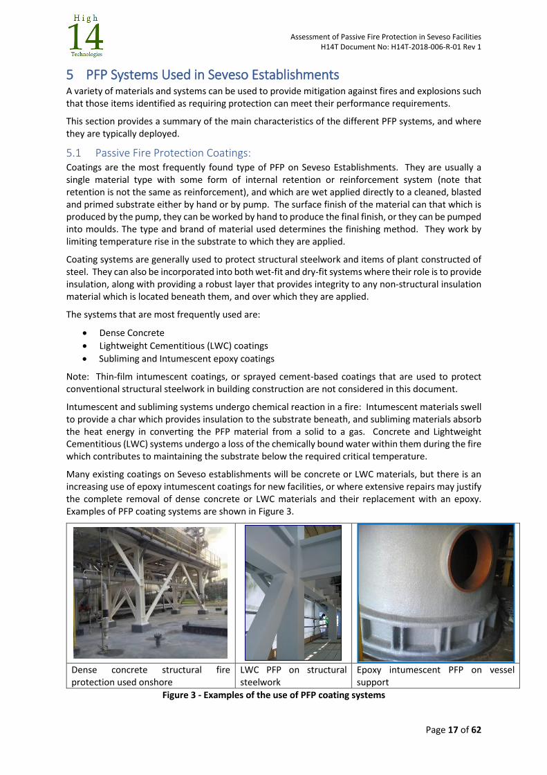
Many existing coatings on Seveso establishments will be concrete or LWC materials, but there is an increasing use of epoxy intumescent coatings for new facilities, or where extensive repairs may justify the complete removal of dense concrete or LWC materials and their replacement with an epoxy. Examples of PFP coating systems are shown in Figure 3.
Dense concrete structural fire protection used onshore
LWC PFP on structural steelwork
Epoxy intumescent PFP on vessel support
Figure 3 - Examples of the use of PFP coating systems
Assessment of Passive Fire Protection in Seveso Facilities H14T Document No: H14T-2018-006-R-01 Rev 1
Page 18 of 62
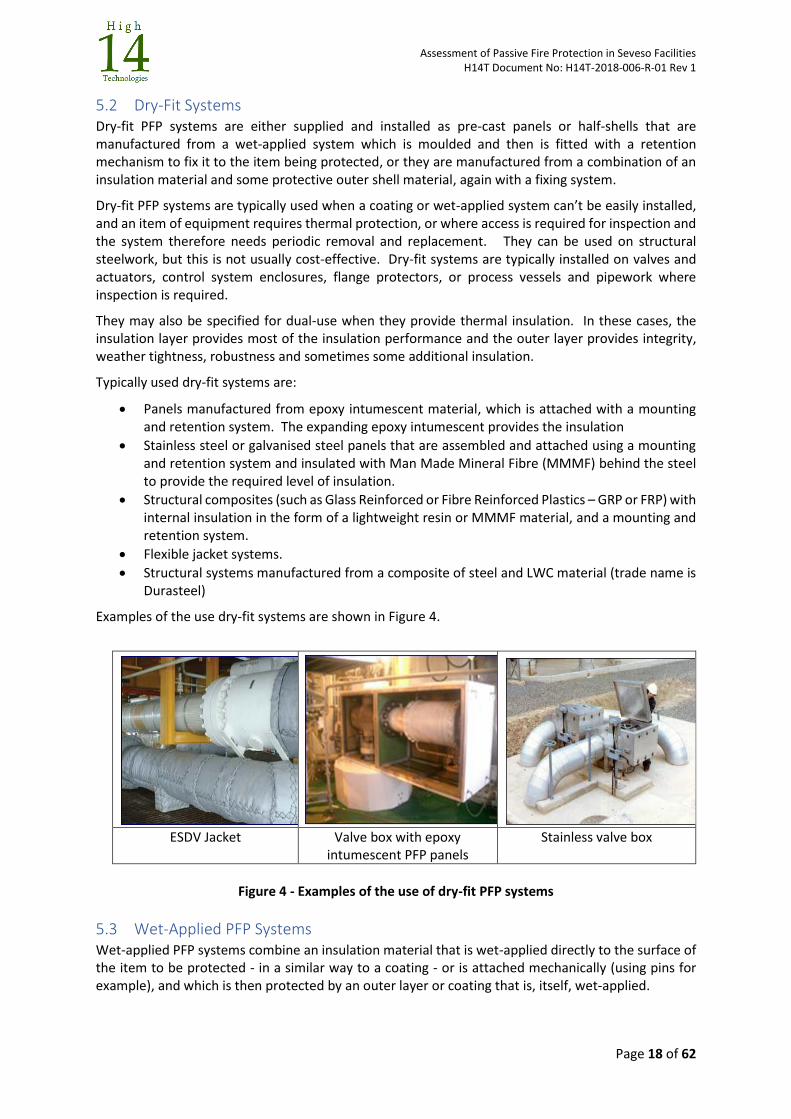
5.2 Dry-Fit Systems Dry-fit PFP systems are either supplied and installed as pre-cast panels or half-shells that are manufactured from a wet-applied system which is moulded and then is fitted with a retention mechanism to fix it to the item being protected, or they are manufactured from a combination of an insulation material and some protective outer shell material, again with a fixing system.
Dry-fit PFP systems are typically used when a coating or wet-applied system can’t be easily installed, and an item of equipment requires thermal protection, or where access is required for inspection and the system therefore needs periodic removal and replacement. They can be used on structural steelwork, but this is not usually cost-effective. Dry-fit systems are typically installed on valves and actuators, control system enclosures, flange protectors, or process vessels and pipework where inspection is required.
They may also be specified for dual-use when they provide thermal insulation. In these cases, the insulation layer provides most of the insulation performance and the outer layer provides integrity, weather tightness, robustness and sometimes some additional insulation.
Typically used dry-fit systems are:
Panels manufactured from epoxy intumescent material, which is attached with a mounting and retention system. The expanding epoxy intumescent provides the insulation
Stainless steel or galvanised steel panels that are assembled and attached using a mounting and retention system and insulated with Man Made Mineral Fibre (MMMF) behind the steel to provide the required level of insulation.
Structural composites (such as Glass Reinforced or Fibre Reinforced Plastics – GRP or FRP) with internal insulation in the form of a lightweight resin or MMMF material, and a mounting and retention system.
Flexible jacket systems.
Structural systems manufactured from a composite of steel and LWC material (trade name is Durasteel)
Examples of the use dry-fit systems are shown in Figure 4.
ESDV Jacket Valve box with epoxy intumescent PFP panels
Stainless valve box
Figure 4 - Examples of the use of dry-fit PFP systems
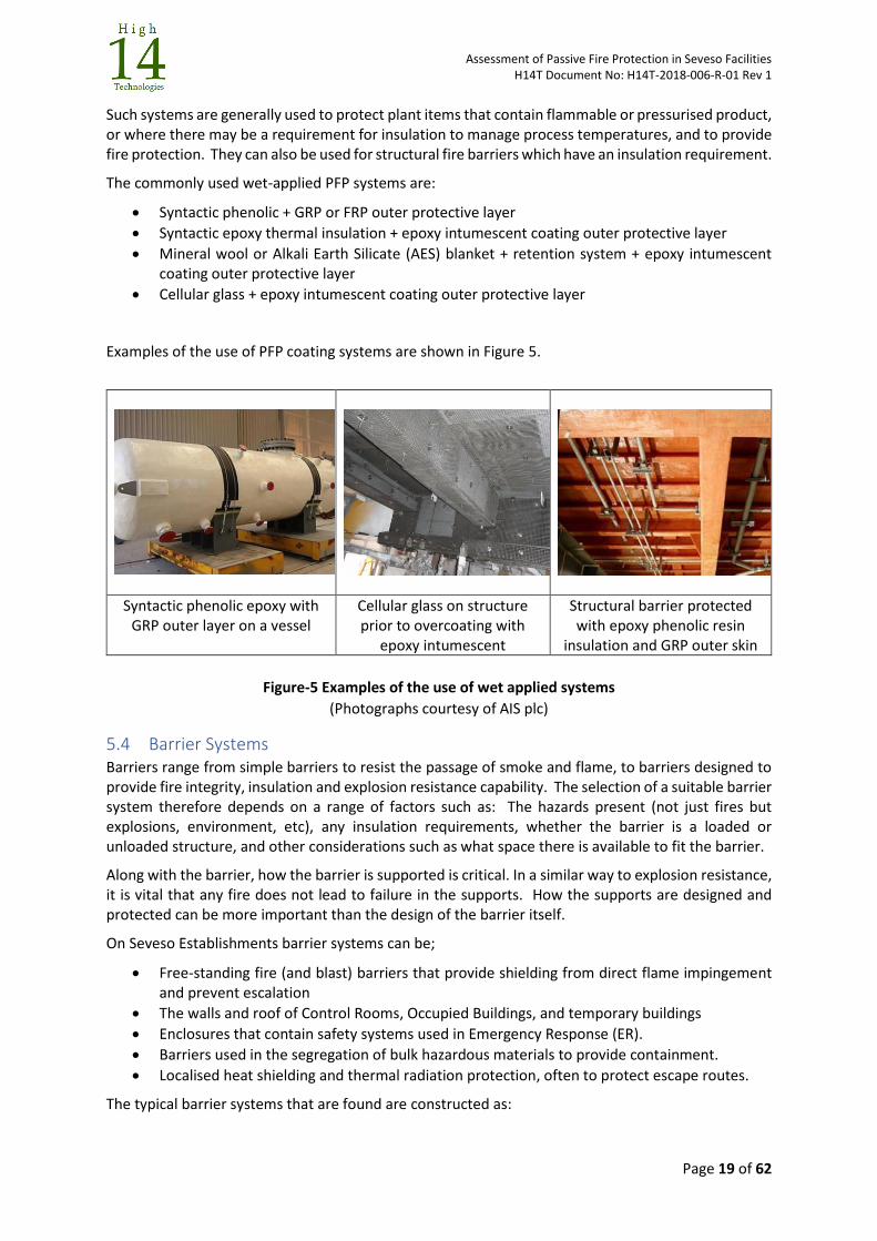
5.3 Wet-Applied PFP Systems Wet-applied PFP systems combine an insulation material that is wet-applied directly to the surface of the item to be protected - in a similar way to a coating - or is attached mechanically (using pins for example), and which is then protected by an outer layer or coating that is, itself, wet-applied.
Assessment of Passive Fire Protection in Seveso Facilities H14T Document No: H14T-2018-006-R-01 Rev 1
Page 19 of 62
Such systems are generally used to protect plant items that contain flammable or pressurised product, or where there may be a requirement for insulation to manage process temperatures, and to provide fire protection. They can also be used for structural fire barriers which have an insulation requirement.
The commonly used wet-applied PFP systems are:
Syntactic phenolic + GRP or FRP outer protective layer
Syntactic epoxy thermal insulation + epoxy intumescent coating outer protective layer
Mineral wool or Alkali Earth Silicate (AES) blanket + retention system + epoxy intumescent coating outer protective layer
Cellular glass + epoxy intumescent coating outer protective layer
Examples of the use of PFP coating systems are shown in Figure 5.
Syntactic phenolic epoxy with GRP outer layer on a vessel
Cellular glass on structure prior to overcoating with
epoxy intumescent
Structural barrier protected with epoxy phenolic resin
insulation and GRP outer skin
Figure-5 Examples of the use of wet applied systems
(Photographs courtesy of AIS plc)
5.4 Barrier Systems Barriers range from simple barriers to resist the passage of smoke and flame, to barriers designed to provide fire integrity, insulation and explosion resistance capability. The selection of a suitable barrier system therefore depends on a range of factors such as: The hazards present (not just fires but explosions, environment, etc), any insulation requirements, whether the barrier is a loaded or unloaded structure, and other considerations such as what space there is available to fit the barrier.
Along with the barrier, how the barrier is supported is critical. In a similar way to explosion resistance, it is vital that any fire does not lead to failure in the supports. How the supports are designed and protected can be more important than the design of the barrier itself.
On Seveso Establishments barrier systems can be;
Free-standing fire (and blast) barriers that provide shielding from direct flame impingement and prevent escalation
The walls and roof of Control Rooms, Occupied Buildings, and temporary buildings
Enclosures that contain safety systems used in Emergency Response (ER).
Barriers used in the segregation of bulk hazardous materials to provide containment.
Localised heat shielding and thermal radiation protection, often to protect escape routes.
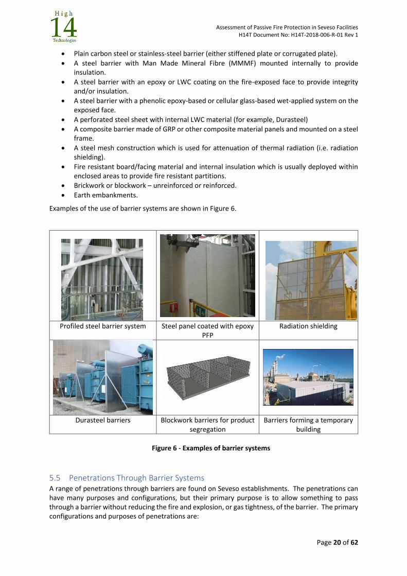
The typical barrier systems that are found are constructed as:
Assessment of Passive Fire Protection in Seveso Facilities H14T Document No: H14T-2018-006-R-01 Rev 1
Page 20 of 62
Plain carbon steel or stainless-steel barrier (either stiffened plate or corrugated plate).
A steel barrier with Man Made Mineral Fibre (MMMF) mounted internally to provide insulation.
A steel barrier with an epoxy or LWC coating on the fire-exposed face to provide integrity and/or insulation.
A steel barrier with a phenolic epoxy-based or cellular glass-based wet-applied system on the exposed face.
A perforated steel sheet with internal LWC material (for example, Durasteel)
A composite barrier made of GRP or other composite material panels and mounted on a steel frame.
A steel mesh construction which is used for attenuation of thermal radiation (i.e. radiation shielding).
Fire resistant board/facing material and internal insulation which is usually deployed within enclosed areas to provide fire resistant partitions.
Brickwork or blockwork – unreinforced or reinforced.
Earth embankments.
Examples of the use of barrier systems are shown in Figure 6.
Profiled steel barrier system Steel panel coated with epoxy PFP
Radiation shielding
Durasteel barriers Blockwork barriers for product segregation
Barriers forming a temporary building
Figure 6 - Examples of barrier systems
5.5 Penetrations Through Barrier Systems A range of penetrations through barriers are found on Seveso establishments. The penetrations can have many purposes and configurations, but their primary purpose is to allow something to pass through a barrier without reducing the fire and explosion, or gas tightness, of the barrier. The primary configurations and purposes of penetrations are:

Assessment of Passive Fire Protection in Seveso Facilities H14T Document No: H14T-2018-006-R-01 Rev 1
Page 21 of 62
Pipe Penetrations o Certified Gaiter Type o Certified Mastic Sealing o Certified Pipe Collars o Other tested bespoke designs o Other non-tested Bespoke Designs
Cable Transits
Doors (Fire rated, Fire and Blast rated etc.)
Windows (Fire rated, Fire and Blast rated etc.)
Ducts (including short sections which support dampers, etc) The penetration must maintain the function of the barrier, which means it will often have to provide an effective seal which does not reduce the fire and blast, or gas-tight, performance of the barrier during an incident. Often, when penetrations through a barrier are present, people or critical systems are also present.
Examples of penetrations are shown in Figure 7.
Pipe collar penetration system Mastic cable penetration system
Cable penetration using cable transit blocks
Gaiter-type penetration system High integrity pipe penetration
Mastic pipe penetration sealing system
Figure 7 - Examples of pipe and cable penetrations
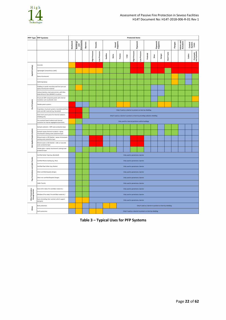
5.6 Typical Uses Table 3 provides an indication of what items the various PFP systems can be used to protect.
Assessment of Passive Fire Protection in Seveso Facilities H14T Document No: H14T-2018-006-R-01 Rev 1
Page 22 of 62
Table 3 – Typical Uses for PFP Systems
PFP Type PFP Systems
Ste
elw
ork
Bu
ild
ing
s
an
d
En
clo
su
res
Barr
iers
Fla
ng
es
Valv
es a
nd
Actu
ato
rs
Hig
h P
ress
ure
Lo
w P
res
su
re
Sad
dle
s
Skir
ts
Fra
me
s
Le
gs
Hig
h P
ress
ure
Lo
w P
res
su
re
Ped
esta
l
Sh
oe
Ha
ng
er
Ste
el F
ram
e
Ca
ble
s
Pn
uem
ati
c
an
d h
yd
rau
lic
Concrete
Lightweight Cementitious (LWC)
Epoxy Intumescent
Subliming Epoxy
Cladding or panels manufactured from pre-cast
epoxy intumescent material
Carbon/stainless steel external skin, with Man
Made Mineral Fibre (MMMF) insulation
Structural GRP composite panels with internal
insulation such as phenolic resin
Flexible jacket systems.
Proprietary structural systems manufactured from
steel and LWC material (e.g. Durasteel)Only if used as a barrier to protect an item by shielding
Steel mesh construction for thermal radiation
shielding onlyOnly if used as a barrier to protect an item by providing radiation shielding
Fire resistant board material and internal
insulation for internal segregation/partitions.Only used for internal partitions within buildings
Syntactic phenolic + GRP outer protective layer
Syntactic epoxy thermal insulation + epoxy
intumescent coating outer protective layer
Mineral wool or AES blanket + epoxy intumescent
coating outer protective layer
Mineral wool or AES blanket + LWC or Concrete
outer protective layer
Cellular glass + epoxy intumescent coating outer
protective layer
Certified Gaiter Type (e.g. Bestobell) Only used to penetrate a barrier
Certified Mastic Sealing (e.g. Rise) Only used to penetrate a barrier
Certified Pipe Collars (e.g. Roxtec) Only used to penetrate a barrier
Other certified bespoke designs Only used to penetrate a barrier
Other non-certified Bespoke Designs Only used to penetrate a barrier
Cable Transits Only used to penetrate a barrier
Doors (Fire rated, Fire and Blast rated etc.) Only used to penetrate a barrier
Windows (Fire rated, Fire and Blast rated etc.) Only used to penetrate a barrier
Ducts (including short sections which support
dampers)Only used to penetrate a barrier
Brick protection Only if used as a barrier to protect an item by shielding
Earth protection Only if used as a barrier to protect an item by shielding
Oth
ers
Dry
-Fit
Sys
tem
s
Pip
ew
ork
Su
pp
ort
s
Pip
ew
ork
Oth
er P
enet
rati
on
s
thro
ugh
bar
rier
s
Vessels
Ap
plie
d C
oat
ings
Wet
-Ap
plie
d D
up
lex
Syst
ems
Pip
e P
enet
rati
on
s an
d C
able
Tra
nsi
ts
Vessel
Su
pp
ort
s
Co
ntr
ol
Syste
m
Lin
es
Protected Items
Assessment of Passive Fire Protection in Seveso Facilities H14T Document No: H14T-2018-006-R-01 Rev 1
Page 23 of 62
6 Defining PFP Performance
6.1 The Importance of Assessing Suitability
In assessing fitness-for-purpose it is essential to understand how the performance of PFP systems is
demonstrated to ensure that a PFP material or system is fundamentally suitable, regardless of its
condition, to mitigate the fire hazards that it will be exposed to. This is not always the case,
particularly on older establishments.
The assessment of the suitability of any PFP system should be based on having a specification that
clearly describes how the PFP is required to perform and then examining the evidence, often provided
by the suppliers of PFP systems, that the performance specification can be met.
The required performance will cover not just performance in a fire, but other factors that might
influence selection such as environment, process conditions, operational requirements, or other
hazards such as explosions. Many problems will arise because the PFP system is fundamentally
unsuitable for the fire hazards or has failed to recognise other factors that have led to the system
becoming damaged.
6.2 Factors to Specify how PFP Should Perform During a Fire
The risk assessments, fire risk assessments and all evaluations for a facility will define the fire hazards,
the items that need to be protected, and the duration that the system should provide protection to
manage the risks to human health and the environment. The essential data that must be
communicated is:
The type of fire (discussed in 3.2).
The items or areas which must be protected (discussed in 4.1).
The failure condition that must be prevented (described in 4.3)
The duration that the PFP system should prevent this failure (discussed in 4.1)
This data can be developed using prescriptive guidance in which all the key parameters are identified
by Code of Practice, Standard or guidance that is being used to specify the fire protection on the
establishment, or through a process in which the operator determines these parameters for the
facility through analysis and assessment.
Regardless of the methods used during any studies to identify this information, this is the key data
that must then be compared against the information available on system performance to identify
suitability.
The demonstration of PFP performance can be provided by Type Approval, Certification, test,
experience or analysis. Whatever method is used, there must be a clear proof that the capability of
the PFP system meets, or exceeds, the required performance criteria.
6.3 Communicating Performance
The performance of PFP (in terms of fire resistance only), is the period (in minutes) during which the
PFP protects the structure or the equipment before the first critical behaviour that described failure
is observed. This required PFP performance is described through a fire rating.
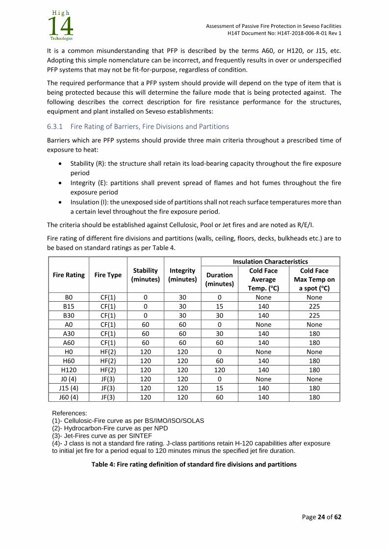
Assessment of Passive Fire Protection in Seveso Facilities H14T Document No: H14T-2018-006-R-01 Rev 1
Page 24 of 62
It is a common misunderstanding that PFP is described by the terms A60, or H120, or J15, etc.
Adopting this simple nomenclature can be incorrect, and frequently results in over or underspecified
PFP systems that may not be fit-for-purpose, regardless of condition.
The required performance that a PFP system should provide will depend on the type of item that is
being protected because this will determine the failure mode that is being protected against. The
following describes the correct description for fire resistance performance for the structures,
equipment and plant installed on Seveso establishments:
6.3.1 Fire Rating of Barriers, Fire Divisions and Partitions
Barriers which are PFP systems should provide three main criteria throughout a prescribed time of
exposure to heat:
Stability (R): the structure shall retain its load-bearing capacity throughout the fire exposure
period
Integrity (E): partitions shall prevent spread of flames and hot fumes throughout the fire
exposure period
Insulation (I): the unexposed side of partitions shall not reach surface temperatures more than
a certain level throughout the fire exposure period.
The criteria should be established against Cellulosic, Pool or Jet fires and are noted as R/E/I.
Fire rating of different fire divisions and partitions (walls, ceiling, floors, decks, bulkheads etc.) are to
be based on standard ratings as per Table 4.
Fire Rating Fire Type Stability
(minutes) Integrity (minutes)
Insulation Characteristics
Duration (minutes)
Cold Face Average
Temp. (oC)
Cold Face Max Temp on
a spot (oC)
B0 CF(1) 0 30 0 None None
B15 CF(1) 0 30 15 140 225
B30 CF(1) 0 30 30 140 225
A0 CF(1) 60 60 0 None None
A30 CF(1) 60 60 30 140 180
A60 CF(1) 60 60 60 140 180
H0 HF(2) 120 120 0 None None
H60 HF(2) 120 120 60 140 180
H120 HF(2) 120 120 120 140 180
J0 (4) JF(3) 120 120 0 None None
J15 (4) JF(3) 120 120 15 140 180
J60 (4) JF(3) 120 120 60 140 180 References: (1)- Cellulosic-Fire curve as per BS/IMO/ISO/SOLAS (2)- Hydrocarbon-Fire curve as per NPD (3)- Jet-Fires curve as per SINTEF (4)- J class is not a standard fire rating. J-class partitions retain H-120 capabilities after exposure to initial jet fire for a period equal to 120 minutes minus the specified jet fire duration.
Table 4: Fire rating definition of standard fire divisions and partitions
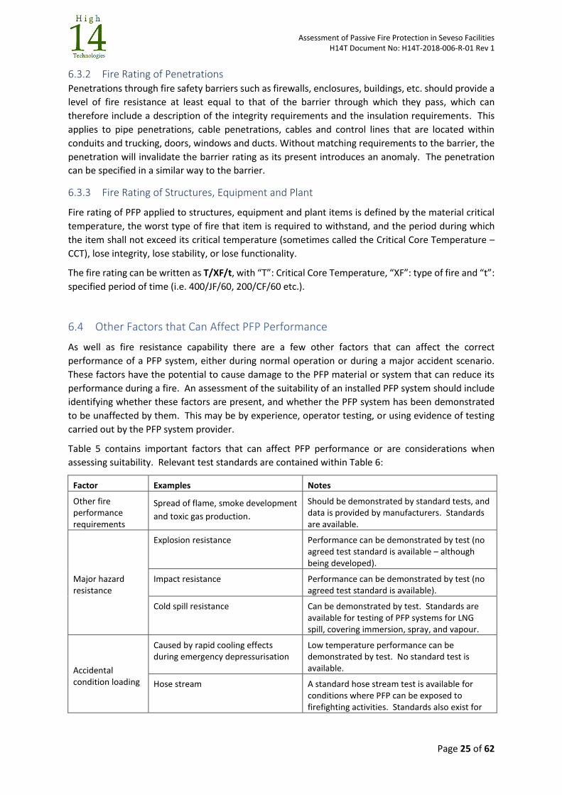
Assessment of Passive Fire Protection in Seveso Facilities H14T Document No: H14T-2018-006-R-01 Rev 1
Page 25 of 62
6.3.2 Fire Rating of Penetrations Penetrations through fire safety barriers such as firewalls, enclosures, buildings, etc. should provide a
level of fire resistance at least equal to that of the barrier through which they pass, which can
therefore include a description of the integrity requirements and the insulation requirements. This
applies to pipe penetrations, cable penetrations, cables and control lines that are located within
conduits and trucking, doors, windows and ducts. Without matching requirements to the barrier, the
penetration will invalidate the barrier rating as its present introduces an anomaly. The penetration
can be specified in a similar way to the barrier.
6.3.3 Fire Rating of Structures, Equipment and Plant
Fire rating of PFP applied to structures, equipment and plant items is defined by the material critical
temperature, the worst type of fire that item is required to withstand, and the period during which
the item shall not exceed its critical temperature (sometimes called the Critical Core Temperature –
CCT), lose integrity, lose stability, or lose functionality.
The fire rating can be written as T/XF/t, with “T”: Critical Core Temperature, “XF”: type of fire and “t”:
specified period of time (i.e. 400/JF/60, 200/CF/60 etc.).
6.4 Other Factors that Can Affect PFP Performance
As well as fire resistance capability there are a few other factors that can affect the correct
performance of a PFP system, either during normal operation or during a major accident scenario.
These factors have the potential to cause damage to the PFP material or system that can reduce its
performance during a fire. An assessment of the suitability of an installed PFP system should include
identifying whether these factors are present, and whether the PFP system has been demonstrated
to be unaffected by them. This may be by experience, operator testing, or using evidence of testing
carried out by the PFP system provider.
Table 5 contains important factors that can affect PFP performance or are considerations when
assessing suitability. Relevant test standards are contained within Table 6:
Factor Examples Notes
Other fire performance requirements
Spread of flame, smoke development
and toxic gas production.
Should be demonstrated by standard tests, and data is provided by manufacturers. Standards are available.
Major hazard resistance
Explosion resistance
Performance can be demonstrated by test (no agreed test standard is available – although being developed).
Impact resistance Performance can be demonstrated by test (no agreed test standard is available).
Cold spill resistance
Can be demonstrated by test. Standards are available for testing of PFP systems for LNG spill, covering immersion, spray, and vapour.
Accidental condition loading
Caused by rapid cooling effects during emergency depressurisation
Low temperature performance can be demonstrated by test. No standard test is available.
Hose stream A standard hose stream test is available for conditions where PFP can be exposed to firefighting activities. Standards also exist for
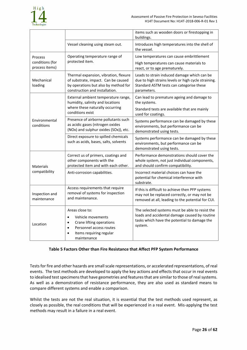
Assessment of Passive Fire Protection in Seveso Facilities H14T Document No: H14T-2018-006-R-01 Rev 1
Page 26 of 62
items such as wooden doors or firestopping in buildings.
Vessel cleaning using steam out. Introduces high temperatures into the shell of the vessel.
Process conditions (for process items)
Operating temperature range of protected item.
Low temperatures can cause embrittlement
High temperatures can cause materials to react, or to age prematurely.
Mechanical loading
Thermal expansion, vibration, flexure of substrate, impact. Can be caused by operations but also by method for construction and installation.
Leads to strain induced damage which can be due to high strains levels or high cycle straining. Standard ASTM tests can categorise these parameters.
Environmental conditions
External ambient temperature range, humidity, salinity and locations where these naturally occurring conditions exist
Can lead to premature ageing and damage to the systems.
Standard tests are available that are mainly used for coatings.
Presence of airborne pollutants such as acidic gases (nitrogen oxides (NOx) and sulphur oxides (SOx)), etc.
Systems performance can be damaged by these environments, but performance can be demonstrated using tests.
Direct exposure to spilled chemicals such as acids, bases, salts, solvents
Systems performance can be damaged by these environments, but performance can be demonstrated using tests.
Materials compatibility
Correct us of primers, coatings and other components with the protected item and with each other.
Performance demonstrations should cover the whole system, not just individual components, and should confirm compatibility.
Anti-corrosion capabilities. Incorrect material choices can have the potential for chemical interference with substrate.
Inspection and maintenance
Access requirements that require removal of systems for inspection and maintenance.
If this is difficult to achieve then PFP systems may not be replaced correctly, or may not be removed at all, leading to the potential for CUI.
Location
Areas close to:
Vehicle movements
Crane lifting operations
Personnel access routes
Items requiring regular maintenance
The selected systems must be able to resist the loads and accidental damage caused by routine tasks which have the potential to damage the system.
Table 5 Factors Other than Fire Resistance that Affect PFP System Performance
Tests for fire and other hazards are small scale representations, or accelerated representations, of real events. The test methods are developed to apply the key actions and effects that occur in real events to idealised test specimens that have geometries and features that are similar to those of real systems. As well as a demonstration of resistance performance, they are also used as standard means to compare different systems and enable a comparison. Whilst the tests are not the real situation, it is essential that the test methods used represent, as closely as possible, the real conditions that will be experienced in a real event. Mis-applying the test methods may result in a failure in a real event.
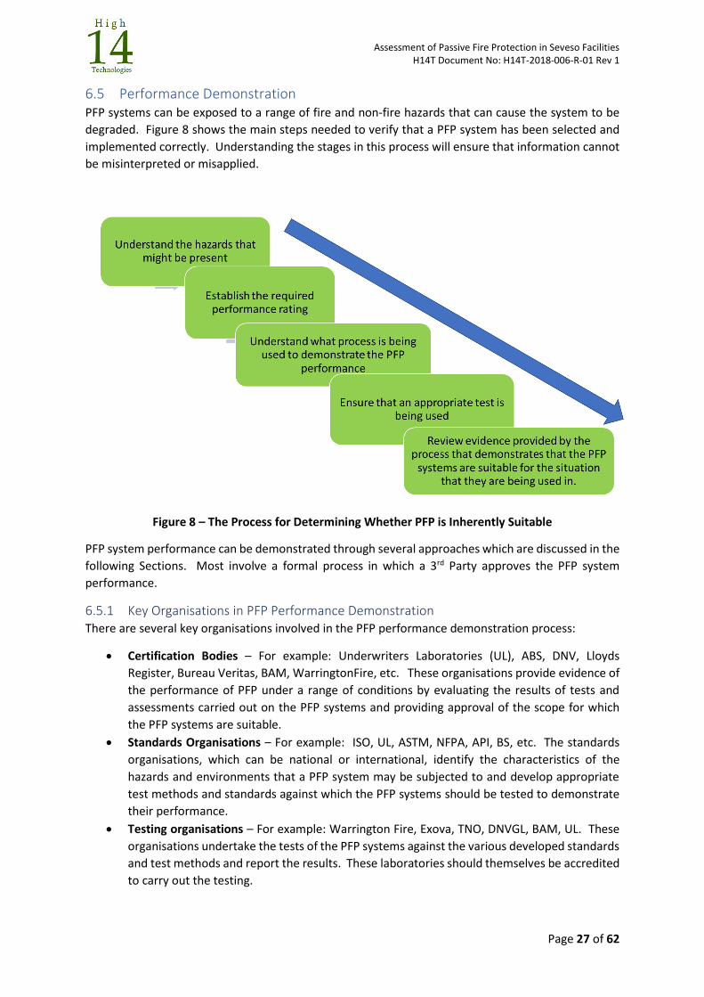
Assessment of Passive Fire Protection in Seveso Facilities H14T Document No: H14T-2018-006-R-01 Rev 1
Page 27 of 62
6.5 Performance Demonstration PFP systems can be exposed to a range of fire and non-fire hazards that can cause the system to be
degraded. Figure 8 shows the main steps needed to verify that a PFP system has been selected and
implemented correctly. Understanding the stages in this process will ensure that information cannot
be misinterpreted or misapplied.
Figure 8 – The Process for Determining Whether PFP is Inherently Suitable
PFP system performance can be demonstrated through several approaches which are discussed in the
following Sections. Most involve a formal process in which a 3rd Party approves the PFP system
performance.
6.5.1 Key Organisations in PFP Performance Demonstration There are several key organisations involved in the PFP performance demonstration process:
Certification Bodies – For example: Underwriters Laboratories (UL), ABS, DNV, Lloyds
Register, Bureau Veritas, BAM, WarringtonFire, etc. These organisations provide evidence of
the performance of PFP under a range of conditions by evaluating the results of tests and
assessments carried out on the PFP systems and providing approval of the scope for which
the PFP systems are suitable.
Standards Organisations – For example: ISO, UL, ASTM, NFPA, API, BS, etc. The standards
organisations, which can be national or international, identify the characteristics of the
hazards and environments that a PFP system may be subjected to and develop appropriate
test methods and standards against which the PFP systems should be tested to demonstrate
their performance.
Testing organisations – For example: Warrington Fire, Exova, TNO, DNVGL, BAM, UL. These
organisations undertake the tests of the PFP systems against the various developed standards
and test methods and report the results. These laboratories should themselves be accredited
to carry out the testing.
Assessment of Passive Fire Protection in Seveso Facilities H14T Document No: H14T-2018-006-R-01 Rev 1
Page 28 of 62
The Manufacturers/Suppliers – Multiple companies. Manufacturers and suppliers submit
their materials and systems to be tested against the standards to gain approval and
accreditation by the Certification Bodies on the conditions for which their systems have been
assessed as appropriate. Suppliers of PFP systems may design bespoke systems by assembling
components from different manufacturers into a system, which is then tested.
The Establishment Owners – Multiple companies. The Establishment Owners have the
responsibility, either directly or through subcontractors, for determining the route that should
be taken for demonstrating the performance of PFP system to the procurement of a system
that has a suitable demonstration that it provides the correct mitigation.
These organisations interact in different ways to produce alternative routes to demonstrating the
performance of a PFP system. It is essential to understand these routes to ensure that a PFP system
has a suitably rigorous demonstration of performance that its being used correctly for the hazards on
a facility.
6.5.2 Processes for Demonstrating Performance The following processes are typically used to demonstrate performance. The choice of process
adopted can be a requirement set by regulation, company preference or project preference.
Type Approval
Type Approval is granted to a product that meets a minimum set of regulatory, technical and safety
requirements. Classification Societies issue Type Approvals. With a Type Approval process, products
are type approved against the requirements of an agreed standard or set of standards. Standards can
be national (for example, flag administration requirements from bodies such as the UK MCA and
Transport Canada); international (for example, ISO Standards) or any other type of specific
requirement (for example, the Certification Authorities own “Rules”. The tests are undertaken, and
the results evaluated using an agreed data assessment process.
The type approval process also includes an ongoing (often annual) audit of the manufacturing process,
ongoing product re-verification, a requirement to declare changes to products amongst others. A
revision of the tests and methods in the Type Approval process may result in a requirement to retest
and revalidate.
A certificate number is provided, and an Approval Mark can be displayed, that demonstrates the
compliance with the tests for the range of products tested and the products are listed in the
Certification Bodies List of Type Approved Products, along with the scope of application. Products can
be compared directly against each other because the testing process is fixed.
Certification
Certification (or Specification Testing) of products is similar to Type Approval of products but the
primary difference is that the issued certificate doesn’t apply across a range of standards but generally
only one – for example pool fire resistance. PFP system certification is the process of certifying that a
system has passed a performance test tests, and meets qualification criteria stipulated in contracts,
regulations, or specifications. Different certificates may be grouped together as a certification
scheme.
With the certification process, tests are again carried and are witnessed by the Certification Body. A
certificate is issued that confirms the test arrangement and the range of parameters over which the
certificate is valid. Often an issued certificate will have drawings and technical details which confirm
the test configuration.
Assessment of Passive Fire Protection in Seveso Facilities H14T Document No: H14T-2018-006-R-01 Rev 1
Page 29 of 62
Certification Bodies will vary in the way that they assess and interpret data from the tests undertaken,
and this can often mean that the scope of applicability can differ between different Certification
Bodies. For instance, thickness of PFP needed to produce a fire resistance response can be different
for different Certification Bodies, even though the test is the same. Projects, Owners and Regulators
may specify the adoption of a particular Certification Body, which means that Manufacturers will aim
to get certifications from a range of different Certification Bodies because that enables wider use of
their products.
Certification by Design Verification/Design Assessment
When a test specimen configuration deviates from the standard test specimen setup when used in a
standard test, then an approval can still be granted by a Certification Body. In this instance the test is
witnessed, and the Certificate written specifically so that it is only applicable to that specimen
configuration that was tested.
A certificate can also be granted by a review of the details of the configuration without test, if they
are not sufficiently different from a configuration already tested, or by design calculations that
demonstrate adequacy.
Acceptance of such deviations become easier to achieve if the original testing is thorough, wide
ranging, and well reported.
Approval of a non-standard test by Witness Report
Performance can be demonstrated using a non-standard test of a non-standard test specimen, which
is witnessed by a Certification Body. This arrangement is often developed to demonstrate
performance for a situation or combination of system and hazard. If the project or Owner is willing
to accept the test as a performance demonstration, then it can be used. This approach is outside the
certification process and has limited applicability.
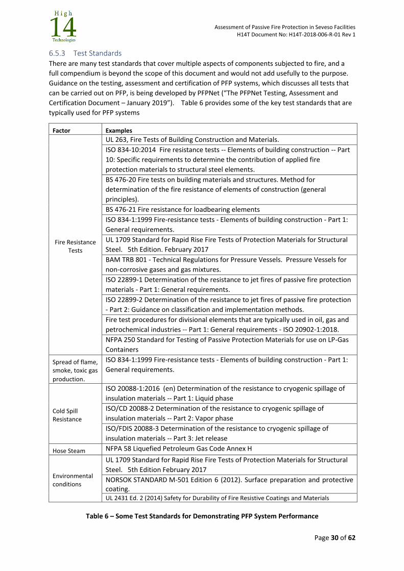
Assessment of Passive Fire Protection in Seveso Facilities H14T Document No: H14T-2018-006-R-01 Rev 1
Page 30 of 62
6.5.3 Test Standards There are many test standards that cover multiple aspects of components subjected to fire, and a
full compendium is beyond the scope of this document and would not add usefully to the purpose.
Guidance on the testing, assessment and certification of PFP systems, which discusses all tests that
can be carried out on PFP, is being developed by PFPNet (“The PFPNet Testing, Assessment and
Certification Document – January 2019”). Table 6 provides some of the key test standards that are
typically used for PFP systems
Factor Examples
Fire Resistance Tests
UL 263, Fire Tests of Building Construction and Materials.
ISO 834-10:2014 Fire resistance tests -- Elements of building construction -- Part
10: Specific requirements to determine the contribution of applied fire
protection materials to structural steel elements.
BS 476-20 Fire tests on building materials and structures. Method for
determination of the fire resistance of elements of construction (general
principles).
BS 476-21 Fire resistance for loadbearing elements
ISO 834-1:1999 Fire-resistance tests - Elements of building construction - Part 1:
General requirements.
UL 1709 Standard for Rapid Rise Fire Tests of Protection Materials for Structural
Steel. 5th Edition. February 2017
BAM TRB 801 - Technical Regulations for Pressure Vessels. Pressure Vessels for
non-corrosive gases and gas mixtures.
ISO 22899-1 Determination of the resistance to jet fires of passive fire protection
materials - Part 1: General requirements.
ISO 22899-2 Determination of the resistance to jet fires of passive fire protection
- Part 2: Guidance on classification and implementation methods.
Fire test procedures for divisional elements that are typically used in oil, gas and
petrochemical industries -- Part 1: General requirements - ISO 20902-1:2018.
NFPA 250 Standard for Testing of Passive Protection Materials for use on LP-Gas
Containers
Spread of flame, smoke, toxic gas
production.
ISO 834-1:1999 Fire-resistance tests - Elements of building construction - Part 1:
General requirements.
Cold Spill Resistance
ISO 20088-1:2016 (en) Determination of the resistance to cryogenic spillage of
insulation materials -- Part 1: Liquid phase
ISO/CD 20088-2 Determination of the resistance to cryogenic spillage of
insulation materials -- Part 2: Vapor phase
ISO/FDIS 20088-3 Determination of the resistance to cryogenic spillage of
insulation materials -- Part 3: Jet release
Hose Steam NFPA 58 Liquefied Petroleum Gas Code Annex H
Environmental conditions
UL 1709 Standard for Rapid Rise Fire Tests of Protection Materials for Structural
Steel. 5th Edition February 2017
NORSOK STANDARD M-501 Edition 6 (2012). Surface preparation and protective coating. UL 2431 Ed. 2 (2014) Safety for Durability of Fire Resistive Coatings and Materials
Table 6 – Some Test Standards for Demonstrating PFP System Performance
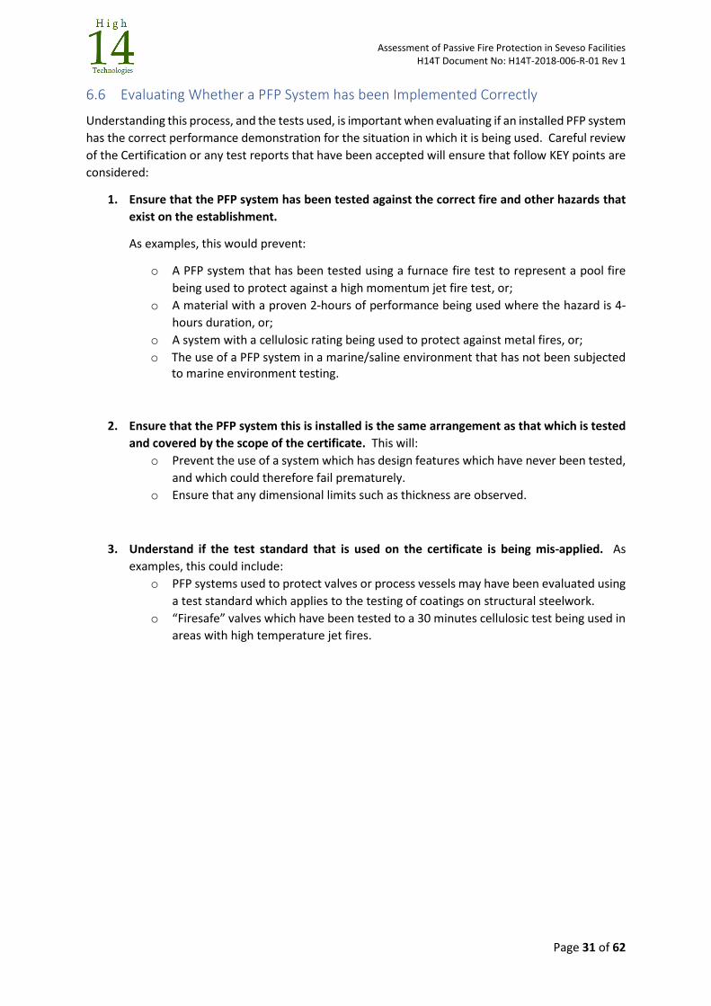
Assessment of Passive Fire Protection in Seveso Facilities H14T Document No: H14T-2018-006-R-01 Rev 1
Page 31 of 62
6.6 Evaluating Whether a PFP System has been Implemented Correctly
Understanding this process, and the tests used, is important when evaluating if an installed PFP system
has the correct performance demonstration for the situation in which it is being used. Careful review
of the Certification or any test reports that have been accepted will ensure that follow KEY points are
considered:
1. Ensure that the PFP system has been tested against the correct fire and other hazards that
exist on the establishment.
As examples, this would prevent:
o A PFP system that has been tested using a furnace fire test to represent a pool fire
being used to protect against a high momentum jet fire test, or;
o A material with a proven 2-hours of performance being used where the hazard is 4-
hours duration, or;
o A system with a cellulosic rating being used to protect against metal fires, or;
o The use of a PFP system in a marine/saline environment that has not been subjected to marine environment testing.
2. Ensure that the PFP system this is installed is the same arrangement as that which is tested
and covered by the scope of the certificate. This will:
o Prevent the use of a system which has design features which have never been tested,
and which could therefore fail prematurely.
o Ensure that any dimensional limits such as thickness are observed.
3. Understand if the test standard that is used on the certificate is being mis-applied. As
examples, this could include:
o PFP systems used to protect valves or process vessels may have been evaluated using
a test standard which applies to the testing of coatings on structural steelwork.
o “Firesafe” valves which have been tested to a 30 minutes cellulosic test being used in
areas with high temperature jet fires.
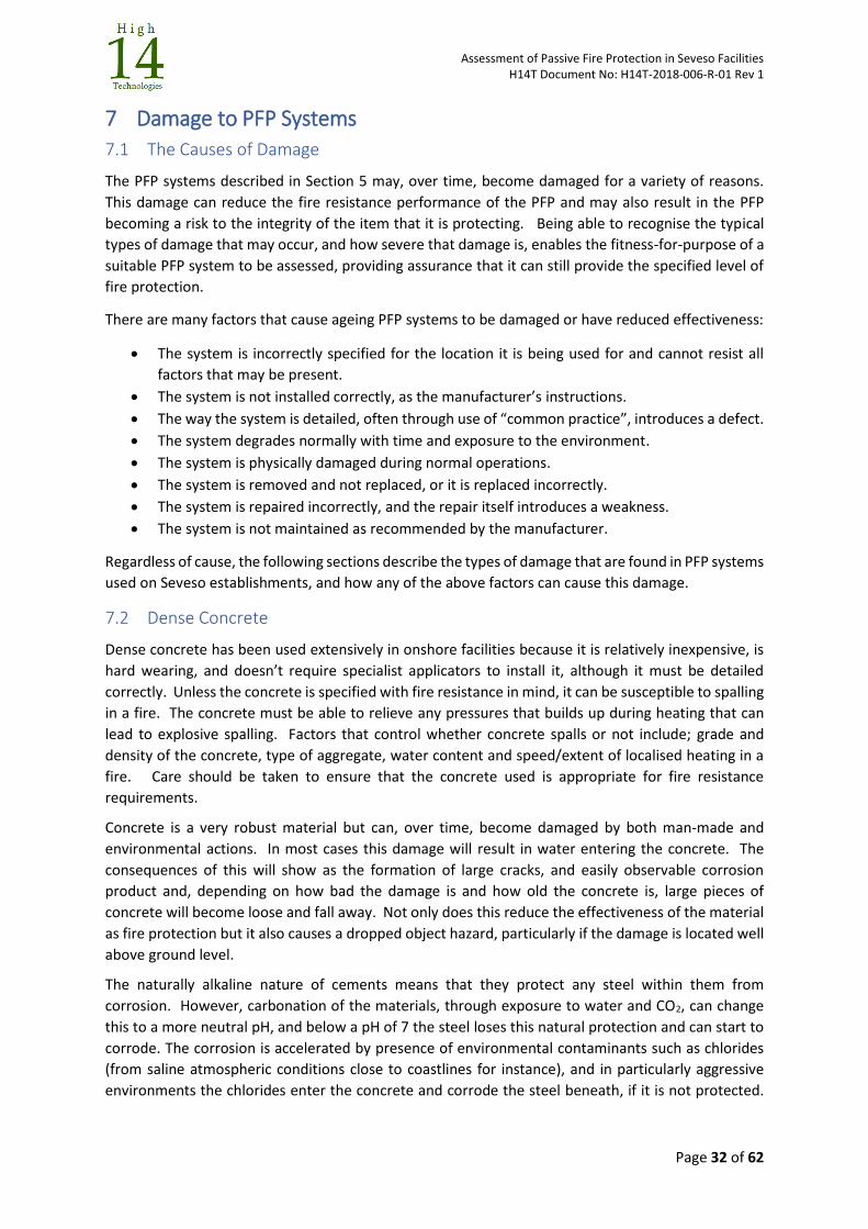
Assessment of Passive Fire Protection in Seveso Facilities H14T Document No: H14T-2018-006-R-01 Rev 1
Page 32 of 62
7 Damage to PFP Systems
7.1 The Causes of Damage
The PFP systems described in Section 5 may, over time, become damaged for a variety of reasons.
This damage can reduce the fire resistance performance of the PFP and may also result in the PFP
becoming a risk to the integrity of the item that it is protecting. Being able to recognise the typical
types of damage that may occur, and how severe that damage is, enables the fitness-for-purpose of a
suitable PFP system to be assessed, providing assurance that it can still provide the specified level of
fire protection.
There are many factors that cause ageing PFP systems to be damaged or have reduced effectiveness:
The system is incorrectly specified for the location it is being used for and cannot resist all
factors that may be present.
The system is not installed correctly, as the manufacturer’s instructions.
The way the system is detailed, often through use of “common practice”, introduces a defect.
The system degrades normally with time and exposure to the environment.
The system is physically damaged during normal operations.
The system is removed and not replaced, or it is replaced incorrectly.
The system is repaired incorrectly, and the repair itself introduces a weakness.
The system is not maintained as recommended by the manufacturer.
Regardless of cause, the following sections describe the types of damage that are found in PFP systems
used on Seveso establishments, and how any of the above factors can cause this damage.
7.2 Dense Concrete
Dense concrete has been used extensively in onshore facilities because it is relatively inexpensive, is
hard wearing, and doesn’t require specialist applicators to install it, although it must be detailed
correctly. Unless the concrete is specified with fire resistance in mind, it can be susceptible to spalling
in a fire. The concrete must be able to relieve any pressures that builds up during heating that can
lead to explosive spalling. Factors that control whether concrete spalls or not include; grade and
density of the concrete, type of aggregate, water content and speed/extent of localised heating in a
fire. Care should be taken to ensure that the concrete used is appropriate for fire resistance
requirements.
Concrete is a very robust material but can, over time, become damaged by both man-made and
environmental actions. In most cases this damage will result in water entering the concrete. The
consequences of this will show as the formation of large cracks, and easily observable corrosion
product and, depending on how bad the damage is and how old the concrete is, large pieces of
concrete will become loose and fall away. Not only does this reduce the effectiveness of the material
as fire protection but it also causes a dropped object hazard, particularly if the damage is located well
above ground level.
The naturally alkaline nature of cements means that they protect any steel within them from
corrosion. However, carbonation of the materials, through exposure to water and CO2, can change
this to a more neutral pH, and below a pH of 7 the steel loses this natural protection and can start to
corrode. The corrosion is accelerated by presence of environmental contaminants such as chlorides
(from saline atmospheric conditions close to coastlines for instance), and in particularly aggressive
environments the chlorides enter the concrete and corrode the steel beneath, if it is not protected.
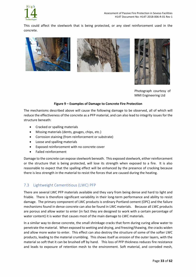
Assessment of Passive Fire Protection in Seveso Facilities H14T Document No: H14T-2018-006-R-01 Rev 1
Page 33 of 62
This could affect the steelwork that is being protected, or any steel reinforcement used in the
concrete.
Photograph courtesy of MMI Engineering Ltd
Figure 9 – Examples of Damage to Concrete Fire Protection
The mechanisms described above will cause the following damage to be observed, all of which will
reduce the effectiveness of the concrete as a PFP material, and can also lead to integrity issues for the
structure beneath:
Cracked or spalling materials
Missing materials (dents, gouges, chips, etc.)
Corrosion staining (from reinforcement or substrate)
Loose and spalling materials
Exposed reinforcement with no concrete cover
Failed reinforcement
Damage to the concrete can expose steelwork beneath. This exposed steelwork, either reinforcement
or the structure that is being protected, will lose its strength when exposed to a fire. It is also
reasonable to expect that the spalling effect will be enhanced by the presence of cracking because
there is less strength in the material to resist the forces that are caused during the heating.
7.3 Lightweight Cementitious (LWC) PFP
There are several LWC PFP materials available and they vary from being dense and hard to light and
friable. There is therefore significant variability in their long-term performance and ability to resist
damage. The primary component of LWC products is ordinary Portland cement (OPC) and the failure
mechanisms found in dense concrete can also be found in LWC materials. Because all LWC products
are porous and allow water to enter (in fact they are designed to work with a certain percentage of
water content) it is water that causes most of the main damage to LWC materials.
In a similar way to dense concrete, the small shrinkage cracks that form during curing allow water to
penetrate the material. When exposed to wetting and drying, and freezing/thawing, the cracks widen
and allow more water to enter. This effect can also destroy the structure of some of the softer LWC
products, leading to the material crumbling. This shows itself as erosion of the outer layers, with the
material so soft that it can be brushed off by hand. This loss of PFP thickness reduces fire resistance
and leads to exposure of retention mesh to the environment. Soft material, and corroded mesh,
Assessment of Passive Fire Protection in Seveso Facilities H14T Document No: H14T-2018-006-R-01 Rev 1
Page 34 of 62
means that the PFP may not survive an explosion event, and will have a reduced fire resistance
performance.
Figure 10 – Examples of Damaged LWC PFP
Photographs courtesy MMI Engineering Ltd
Because LWC materials absorb water, this can lead to corrosion of the reinforcement system (mesh,
lath, pins, washers, etc and the steel beneath (causing CUI problems). This corrosion increases cracking
due to the expansion of the corrosion products, and PFP material can loosen and fall – potentially
causing a dropped object hazard. Using a suitably protected reinforcement system along with a
weatherproofing sealer or topcoat can reduce this damage, although any sealing coats/topcoats must
be maintained to ensure long-term integrity of the LWC materials.
LWC PFP materials are usually restricted to an upper operating temperature of 50°C. If used above
this additional insulation products may be required. Damage has been noted where a change of use
has resulted in a change to operating conditions, which has exposed the LWC PFP to conditions outside
its recommended limits.
Low-density LWC PFP may incur physical damage (chips, abrasions, gouges, etc) in service which also
allow water to enter and reach the steel substrate with potential corrosion problems. This loss of
material is a reduction in thickness and will result in a reduced fire resistance performance. The
importance of this reduction is dependent on the size of the damaged area in relation to the size and
function of the protected component, and how long the fire exposure is.
Section 8 discusses some of the details of LWC (and dense concrete) materials that can result in poor
performance in a fire.
The location of the retention mesh within the LWC material is also important. In older LWC systems
the mesh was attached close to the substrate because the materials were developed and specified for
low momentum pool fires. With jet fires, the higher momentum requires that the mesh is located in
the “middle third” of the material thickness, and this is now always specified when the hazards are
from high momentum jet fires.
Most damage mechanisms will reduce the effectiveness of the LWC as a PFP material, and can also
lead to integrity issues for the protected structure to which they are applied. Permitting water ingress
can result in corrosion of the protected item under the fireproofing for older systems where primers
may have broken down. This condition should also be identified as a priority.
The mechanisms described above will cause the following damage to be observed in LWC PFP systems:
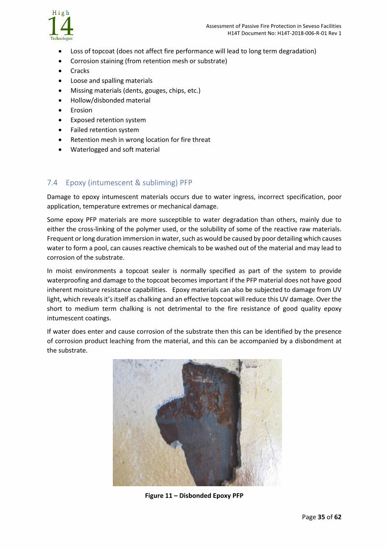
Assessment of Passive Fire Protection in Seveso Facilities H14T Document No: H14T-2018-006-R-01 Rev 1
Page 35 of 62
Loss of topcoat (does not affect fire performance will lead to long term degradation)
Corrosion staining (from retention mesh or substrate)
Cracks
Loose and spalling materials
Missing materials (dents, gouges, chips, etc.)
Hollow/disbonded material
Erosion
Exposed retention system
Failed retention system
Retention mesh in wrong location for fire threat
Waterlogged and soft material
7.4 Epoxy (intumescent & subliming) PFP
Damage to epoxy intumescent materials occurs due to water ingress, incorrect specification, poor
application, temperature extremes or mechanical damage.
Some epoxy PFP materials are more susceptible to water degradation than others, mainly due to
either the cross-linking of the polymer used, or the solubility of some of the reactive raw materials.
Frequent or long duration immersion in water, such as would be caused by poor detailing which causes
water to form a pool, can causes reactive chemicals to be washed out of the material and may lead to
corrosion of the substrate.
In moist environments a topcoat sealer is normally specified as part of the system to provide
waterproofing and damage to the topcoat becomes important if the PFP material does not have good
inherent moisture resistance capabilities. Epoxy materials can also be subjected to damage from UV
light, which reveals it’s itself as chalking and an effective topcoat will reduce this UV damage. Over the
short to medium term chalking is not detrimental to the fire resistance of good quality epoxy
intumescent coatings.
If water does enter and cause corrosion of the substrate then this can be identified by the presence
of corrosion product leaching from the material, and this can be accompanied by a disbondment at
the substrate.
Figure 11 – Disbonded Epoxy PFP
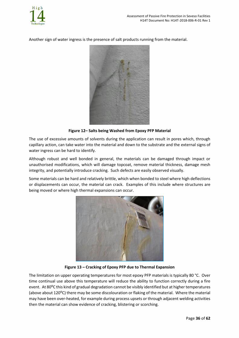
Assessment of Passive Fire Protection in Seveso Facilities H14T Document No: H14T-2018-006-R-01 Rev 1
Page 36 of 62
Another sign of water ingress is the presence of salt products running from the material.
Figure 12– Salts being Washed from Epoxy PFP Material
The use of excessive amounts of solvents during the application can result in pores which, through
capillary action, can take water into the material and down to the substrate and the external signs of
water ingress can be hard to identify.
Although robust and well bonded in general, the materials can be damaged through impact or
unauthorised modifications, which will damage topcoat, remove material thickness, damage mesh
integrity, and potentially introduce cracking. Such defects are easily observed visually.
Some materials can be hard and relatively brittle, which when bonded to steel where high deflections
or displacements can occur, the material can crack. Examples of this include where structures are
being moved or where high thermal expansions can occur.
Figure 13 – Cracking of Epoxy PFP due to Thermal Expansion
The limitation on upper operating temperatures for most epoxy PFP materials is typically 80 °C. Over
time continual use above this temperature will reduce the ability to function correctly during a fire
event. At 80⁰C this kind of gradual degradation cannot be visibly identified but at higher temperatures
(above about 120⁰C) there may be some discolouration or flaking of the material. Where the material
may have been over-heated, for example during process upsets or through adjacent welding activities
then the material can show evidence of cracking, blistering or scorching.
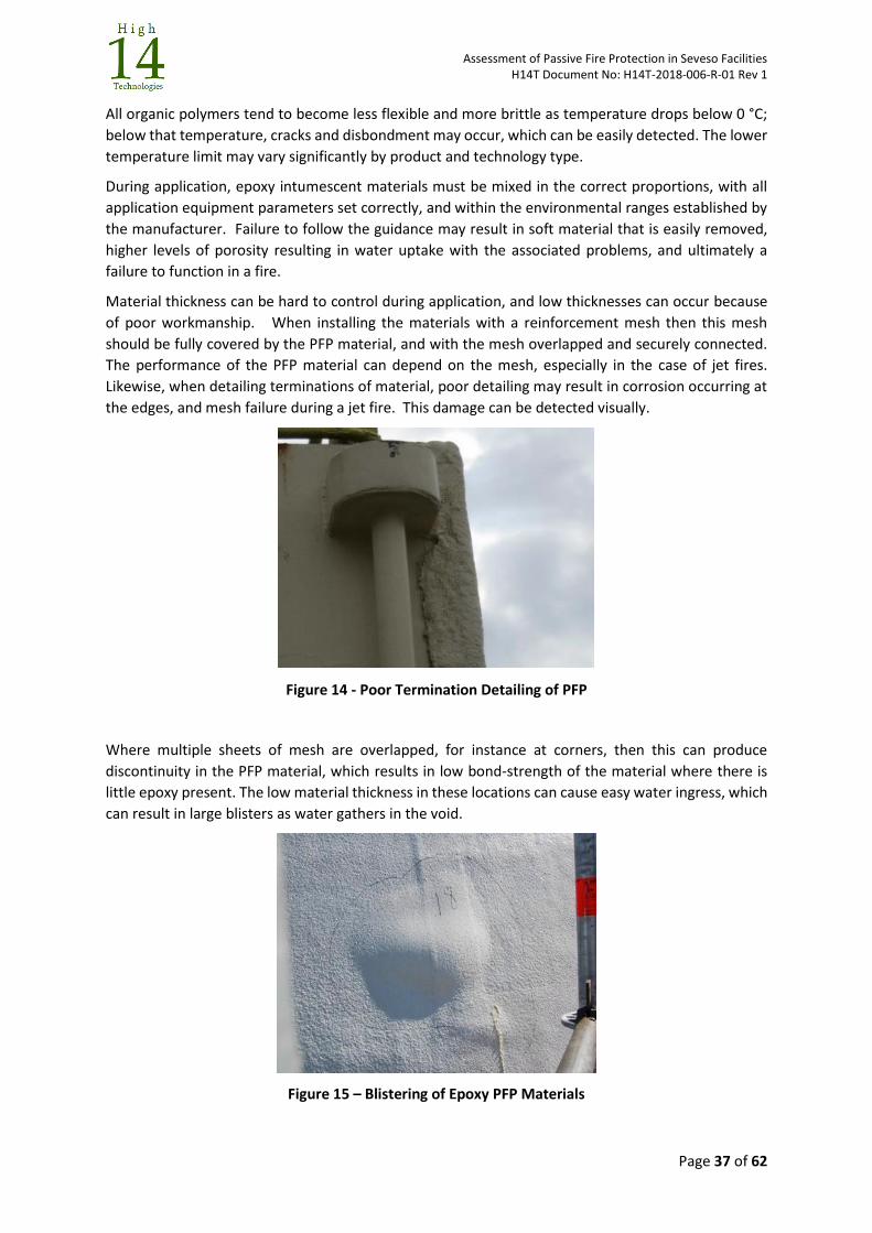
Assessment of Passive Fire Protection in Seveso Facilities H14T Document No: H14T-2018-006-R-01 Rev 1
Page 37 of 62
All organic polymers tend to become less flexible and more brittle as temperature drops below 0 °C;
below that temperature, cracks and disbondment may occur, which can be easily detected. The lower
temperature limit may vary significantly by product and technology type.
During application, epoxy intumescent materials must be mixed in the correct proportions, with all
application equipment parameters set correctly, and within the environmental ranges established by
the manufacturer. Failure to follow the guidance may result in soft material that is easily removed,
higher levels of porosity resulting in water uptake with the associated problems, and ultimately a
failure to function in a fire.
Material thickness can be hard to control during application, and low thicknesses can occur because
of poor workmanship. When installing the materials with a reinforcement mesh then this mesh
should be fully covered by the PFP material, and with the mesh overlapped and securely connected.
The performance of the PFP material can depend on the mesh, especially in the case of jet fires.
Likewise, when detailing terminations of material, poor detailing may result in corrosion occurring at
the edges, and mesh failure during a jet fire. This damage can be detected visually.
Figure 14 - Poor Termination Detailing of PFP
Where multiple sheets of mesh are overlapped, for instance at corners, then this can produce
discontinuity in the PFP material, which results in low bond-strength of the material where there is
little epoxy present. The low material thickness in these locations can cause easy water ingress, which
can result in large blisters as water gathers in the void.
Figure 15 – Blistering of Epoxy PFP Materials
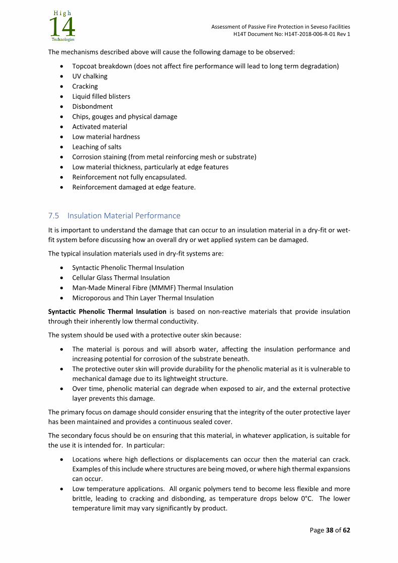
Assessment of Passive Fire Protection in Seveso Facilities H14T Document No: H14T-2018-006-R-01 Rev 1
Page 38 of 62
The mechanisms described above will cause the following damage to be observed:
Topcoat breakdown (does not affect fire performance will lead to long term degradation)
UV chalking
Cracking
Liquid filled blisters
Disbondment
Chips, gouges and physical damage
Activated material
Low material hardness
Leaching of salts
Corrosion staining (from metal reinforcing mesh or substrate)
Low material thickness, particularly at edge features
Reinforcement not fully encapsulated.
Reinforcement damaged at edge feature.
7.5 Insulation Material Performance
It is important to understand the damage that can occur to an insulation material in a dry-fit or wet-
fit system before discussing how an overall dry or wet applied system can be damaged.
The typical insulation materials used in dry-fit systems are:
Syntactic Phenolic Thermal Insulation
Cellular Glass Thermal Insulation
Man-Made Mineral Fibre (MMMF) Thermal Insulation
Microporous and Thin Layer Thermal Insulation
Syntactic Phenolic Thermal Insulation is based on non-reactive materials that provide insulation
through their inherently low thermal conductivity.
The system should be used with a protective outer skin because:
The material is porous and will absorb water, affecting the insulation performance and
increasing potential for corrosion of the substrate beneath.
The protective outer skin will provide durability for the phenolic material as it is vulnerable to
mechanical damage due to its lightweight structure.
Over time, phenolic material can degrade when exposed to air, and the external protective
layer prevents this damage.
The primary focus on damage should consider ensuring that the integrity of the outer protective layer
has been maintained and provides a continuous sealed cover.
The secondary focus should be on ensuring that this material, in whatever application, is suitable for
the use it is intended for. In particular:
Locations where high deflections or displacements can occur then the material can crack.
Examples of this include where structures are being moved, or where high thermal expansions
can occur.
Low temperature applications. All organic polymers tend to become less flexible and more
brittle, leading to cracking and disbonding, as temperature drops below 0°C. The lower
temperature limit may vary significantly by product.
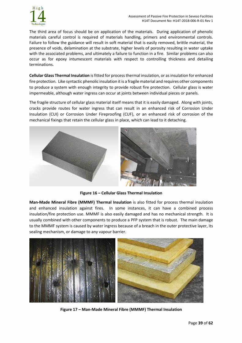
Assessment of Passive Fire Protection in Seveso Facilities H14T Document No: H14T-2018-006-R-01 Rev 1
Page 39 of 62
The third area of focus should be on application of the materials. During application of phenolic materials careful control is required of materials handling, primers and environmental controls. Failure to follow the guidance will result in soft material that is easily removed, brittle material, the presence of voids, delamination at the substrate, higher levels of porosity resulting in water uptake with the associated problems, and ultimately a failure to function in a fire. Similar problems can also occur as for epoxy intumescent materials with respect to controlling thickness and detailing terminations. Cellular Glass Thermal Insulation is fitted for process thermal insulation, or as insulation for enhanced
fire protection. Like syntactic phenolic insulation it is a fragile material and requires other components
to produce a system with enough integrity to provide robust fire protection. Cellular glass is water
impermeable, although water ingress can occur at joints between individual pieces or panels.
The fragile structure of cellular glass material itself means that it is easily damaged. Along with joints,
cracks provide routes for water ingress that can result in an enhanced risk of Corrosion Under
Insulation (CUI) or Corrosion Under Fireproofing (CUF), or an enhanced risk of corrosion of the
mechanical fixings that retain the cellular glass in place, which can lead to it detaching.
Figure 16 – Cellular Glass Thermal Insulation
Man-Made Mineral Fibre (MMMF) Thermal Insulation is also fitted for process thermal insulation
and enhanced insulation against fires. In some instances, it can have a combined process
insulation/fire protection use. MMMF is also easily damaged and has no mechanical strength. It is
usually combined with other components to produce a PFP system that is robust. The main damage
to the MMMF system is caused by water ingress because of a breach in the outer protective layer, its
sealing mechanism, or damage to any vapour barrier.
Figure 17 – Man-Made Mineral Fibre (MMMF) Thermal Insulation
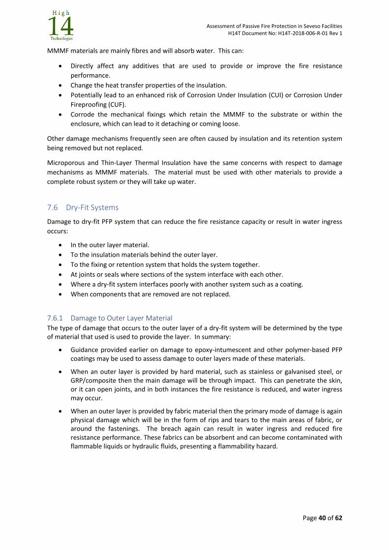
Assessment of Passive Fire Protection in Seveso Facilities H14T Document No: H14T-2018-006-R-01 Rev 1
Page 40 of 62
MMMF materials are mainly fibres and will absorb water. This can:
Directly affect any additives that are used to provide or improve the fire resistance
performance.
Change the heat transfer properties of the insulation.
Potentially lead to an enhanced risk of Corrosion Under Insulation (CUI) or Corrosion Under
Fireproofing (CUF).
Corrode the mechanical fixings which retain the MMMF to the substrate or within the
enclosure, which can lead to it detaching or coming loose.
Other damage mechanisms frequently seen are often caused by insulation and its retention system
being removed but not replaced.
Microporous and Thin-Layer Thermal Insulation have the same concerns with respect to damage
mechanisms as MMMF materials. The material must be used with other materials to provide a
complete robust system or they will take up water.
7.6 Dry-Fit Systems
Damage to dry-fit PFP system that can reduce the fire resistance capacity or result in water ingress
occurs:
In the outer layer material.
To the insulation materials behind the outer layer.
To the fixing or retention system that holds the system together.
At joints or seals where sections of the system interface with each other.
Where a dry-fit system interfaces poorly with another system such as a coating.
When components that are removed are not replaced.
7.6.1 Damage to Outer Layer Material The type of damage that occurs to the outer layer of a dry-fit system will be determined by the type of material that used is used to provide the layer. In summary:
Guidance provided earlier on damage to epoxy-intumescent and other polymer-based PFP coatings may be used to assess damage to outer layers made of these materials.
When an outer layer is provided by hard material, such as stainless or galvanised steel, or GRP/composite then the main damage will be through impact. This can penetrate the skin, or it can open joints, and in both instances the fire resistance is reduced, and water ingress may occur.
When an outer layer is provided by fabric material then the primary mode of damage is again physical damage which will be in the form of rips and tears to the main areas of fabric, or around the fastenings. The breach again can result in water ingress and reduced fire resistance performance. These fabrics can be absorbent and can become contaminated with flammable liquids or hydraulic fluids, presenting a flammability hazard.
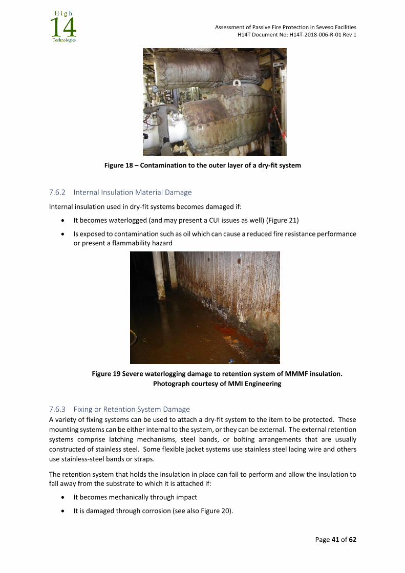
Assessment of Passive Fire Protection in Seveso Facilities H14T Document No: H14T-2018-006-R-01 Rev 1
Page 41 of 62
Figure 18 – Contamination to the outer layer of a dry-fit system
7.6.2 Internal Insulation Material Damage
Internal insulation used in dry-fit systems becomes damaged if:
It becomes waterlogged (and may present a CUI issues as well) (Figure 21)
Is exposed to contamination such as oil which can cause a reduced fire resistance performance or present a flammability hazard
Figure 19 Severe waterlogging damage to retention system of MMMF insulation.
Photograph courtesy of MMI Engineering
7.6.3 Fixing or Retention System Damage A variety of fixing systems can be used to attach a dry-fit system to the item to be protected. These
mounting systems can be either internal to the system, or they can be external. The external retention
systems comprise latching mechanisms, steel bands, or bolting arrangements that are usually
constructed of stainless steel. Some flexible jacket systems use stainless steel lacing wire and others
use stainless-steel bands or straps.
The retention system that holds the insulation in place can fail to perform and allow the insulation to fall away from the substrate to which it is attached if:
It becomes mechanically through impact
It is damaged through corrosion (see also Figure 20).
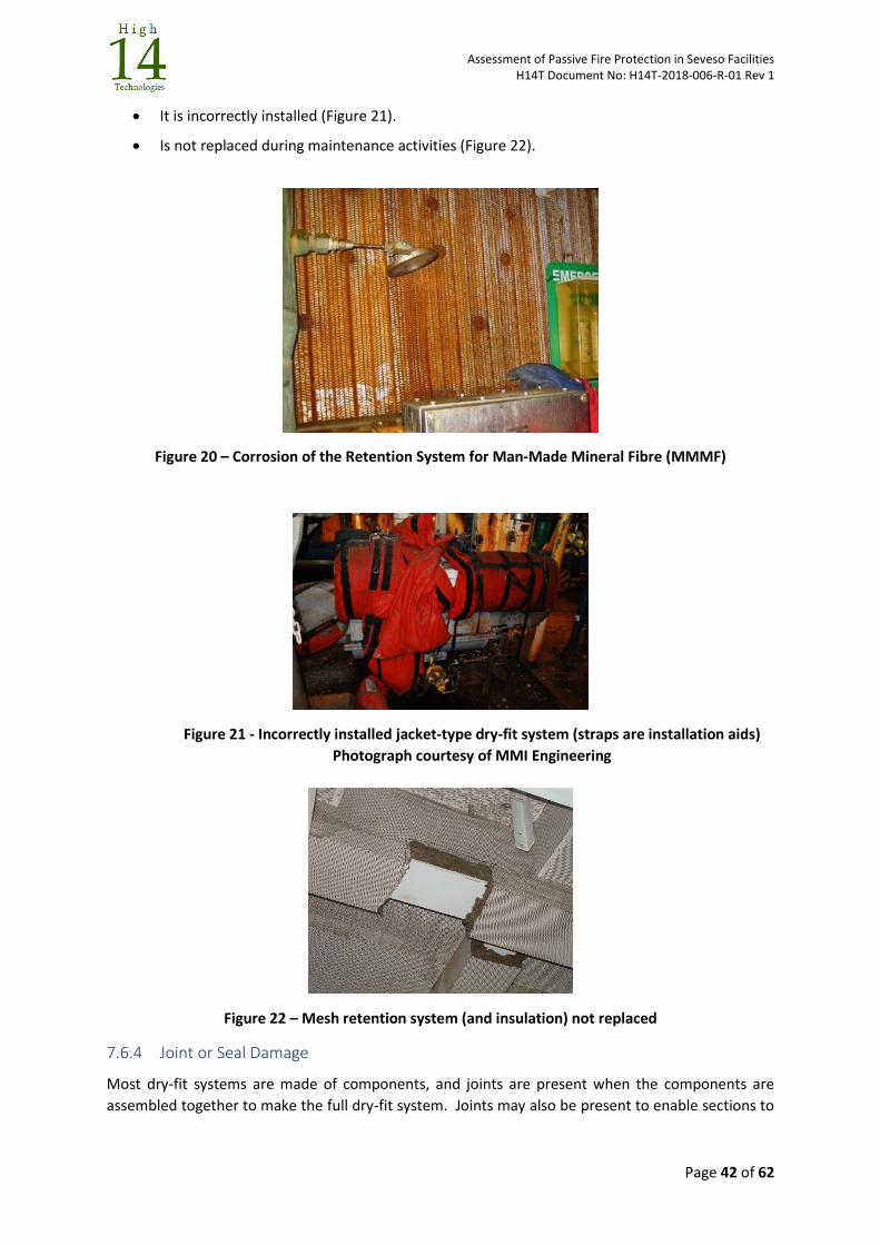
Assessment of Passive Fire Protection in Seveso Facilities H14T Document No: H14T-2018-006-R-01 Rev 1
Page 42 of 62
It is incorrectly installed (Figure 21).
Is not replaced during maintenance activities (Figure 22).
Figure 20 – Corrosion of the Retention System for Man-Made Mineral Fibre (MMMF)
Figure 21 - Incorrectly installed jacket-type dry-fit system (straps are installation aids)
Photograph courtesy of MMI Engineering
Figure 22 – Mesh retention system (and insulation) not replaced
7.6.4 Joint or Seal Damage
Most dry-fit systems are made of components, and joints are present when the components are
assembled together to make the full dry-fit system. Joints may also be present to enable sections to
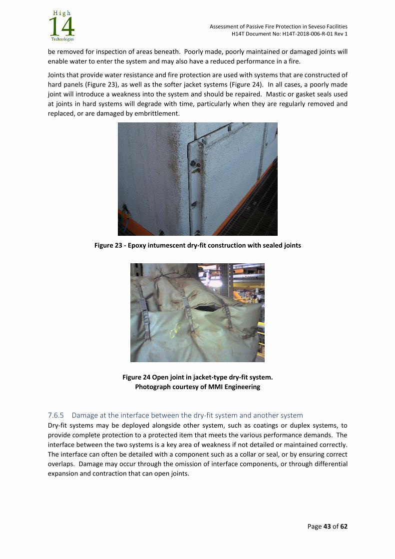
Assessment of Passive Fire Protection in Seveso Facilities H14T Document No: H14T-2018-006-R-01 Rev 1
Page 43 of 62
be removed for inspection of areas beneath. Poorly made, poorly maintained or damaged joints will
enable water to enter the system and may also have a reduced performance in a fire.
Joints that provide water resistance and fire protection are used with systems that are constructed of
hard panels (Figure 23), as well as the softer jacket systems (Figure 24). In all cases, a poorly made
joint will introduce a weakness into the system and should be repaired. Mastic or gasket seals used
at joints in hard systems will degrade with time, particularly when they are regularly removed and
replaced, or are damaged by embrittlement.
Figure 23 - Epoxy intumescent dry-fit construction with sealed joints
Figure 24 Open joint in jacket-type dry-fit system.
Photograph courtesy of MMI Engineering
7.6.5 Damage at the interface between the dry-fit system and another system Dry-fit systems may be deployed alongside other system, such as coatings or duplex systems, to
provide complete protection to a protected item that meets the various performance demands. The
interface between the two systems is a key area of weakness if not detailed or maintained correctly.
The interface can often be detailed with a component such as a collar or seal, or by ensuring correct
overlaps. Damage may occur through the omission of interface components, or through differential
expansion and contraction that can open joints.
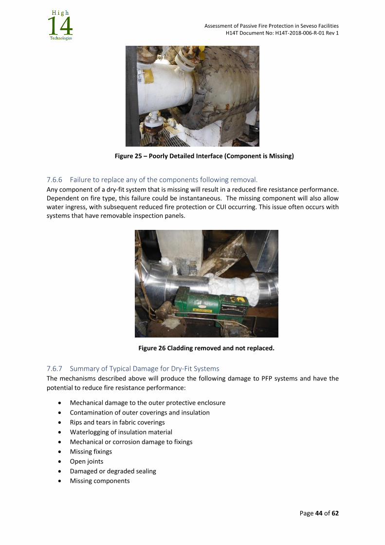
Assessment of Passive Fire Protection in Seveso Facilities H14T Document No: H14T-2018-006-R-01 Rev 1
Page 44 of 62
Figure 25 – Poorly Detailed Interface (Component is Missing)
7.6.6 Failure to replace any of the components following removal. Any component of a dry-fit system that is missing will result in a reduced fire resistance performance. Dependent on fire type, this failure could be instantaneous. The missing component will also allow water ingress, with subsequent reduced fire protection or CUI occurring. This issue often occurs with systems that have removable inspection panels.
Figure 26 Cladding removed and not replaced.
7.6.7 Summary of Typical Damage for Dry-Fit Systems The mechanisms described above will produce the following damage to PFP systems and have the
potential to reduce fire resistance performance:
Mechanical damage to the outer protective enclosure
Contamination of outer coverings and insulation
Rips and tears in fabric coverings
Waterlogging of insulation material
Mechanical or corrosion damage to fixings
Missing fixings
Open joints
Damaged or degraded sealing
Missing components
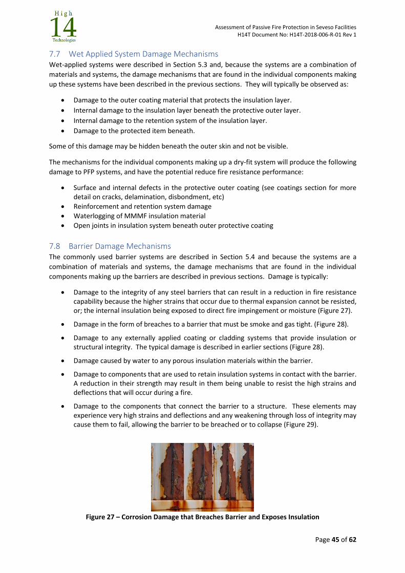
Assessment of Passive Fire Protection in Seveso Facilities H14T Document No: H14T-2018-006-R-01 Rev 1
Page 45 of 62
7.7 Wet Applied System Damage Mechanisms Wet-applied systems were described in Section 5.3 and, because the systems are a combination of
materials and systems, the damage mechanisms that are found in the individual components making
up these systems have been described in the previous sections. They will typically be observed as:
Damage to the outer coating material that protects the insulation layer.
Internal damage to the insulation layer beneath the protective outer layer.
Internal damage to the retention system of the insulation layer.
Damage to the protected item beneath.
Some of this damage may be hidden beneath the outer skin and not be visible.
The mechanisms for the individual components making up a dry-fit system will produce the following
damage to PFP systems, and have the potential reduce fire resistance performance:
Surface and internal defects in the protective outer coating (see coatings section for more detail on cracks, delamination, disbondment, etc)
Reinforcement and retention system damage
Waterlogging of MMMF insulation material
Open joints in insulation system beneath outer protective coating
7.8 Barrier Damage Mechanisms The commonly used barrier systems are described in Section 5.4 and because the systems are a
combination of materials and systems, the damage mechanisms that are found in the individual
components making up the barriers are described in previous sections. Damage is typically:
Damage to the integrity of any steel barriers that can result in a reduction in fire resistance capability because the higher strains that occur due to thermal expansion cannot be resisted, or; the internal insulation being exposed to direct fire impingement or moisture (Figure 27).
Damage in the form of breaches to a barrier that must be smoke and gas tight. (Figure 28).
Damage to any externally applied coating or cladding systems that provide insulation or structural integrity. The typical damage is described in earlier sections (Figure 28).
Damage caused by water to any porous insulation materials within the barrier.
Damage to components that are used to retain insulation systems in contact with the barrier. A reduction in their strength may result in them being unable to resist the high strains and deflections that will occur during a fire.
Damage to the components that connect the barrier to a structure. These elements may experience very high strains and deflections and any weakening through loss of integrity may cause them to fail, allowing the barrier to be breached or to collapse (Figure 29).
Figure 27 – Corrosion Damage that Breaches Barrier and Exposes Insulation
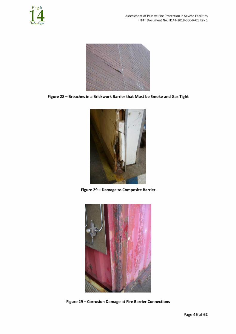
Assessment of Passive Fire Protection in Seveso Facilities H14T Document No: H14T-2018-006-R-01 Rev 1
Page 46 of 62
Figure 28 – Breaches in a Brickwork Barrier that Must be Smoke and Gas Tight
Figure 29 – Damage to Composite Barrier
Figure 29 – Corrosion Damage at Fire Barrier Connections
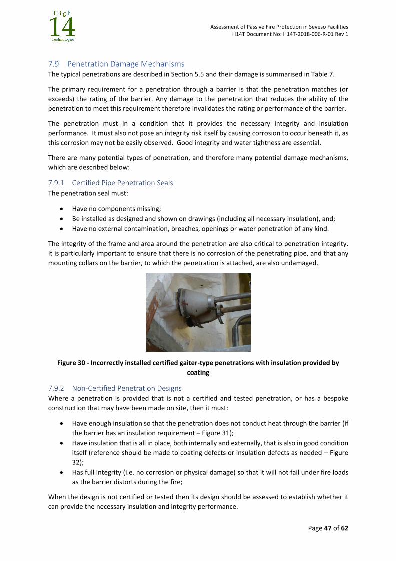
Assessment of Passive Fire Protection in Seveso Facilities H14T Document No: H14T-2018-006-R-01 Rev 1
Page 47 of 62
7.9 Penetration Damage Mechanisms The typical penetrations are described in Section 5.5 and their damage is summarised in Table 7.
The primary requirement for a penetration through a barrier is that the penetration matches (or
exceeds) the rating of the barrier. Any damage to the penetration that reduces the ability of the
penetration to meet this requirement therefore invalidates the rating or performance of the barrier.
The penetration must in a condition that it provides the necessary integrity and insulation
performance. It must also not pose an integrity risk itself by causing corrosion to occur beneath it, as
this corrosion may not be easily observed. Good integrity and water tightness are essential.
There are many potential types of penetration, and therefore many potential damage mechanisms,
which are described below:
7.9.1 Certified Pipe Penetration Seals The penetration seal must:
Have no components missing;
Be installed as designed and shown on drawings (including all necessary insulation), and;
Have no external contamination, breaches, openings or water penetration of any kind.
The integrity of the frame and area around the penetration are also critical to penetration integrity.
It is particularly important to ensure that there is no corrosion of the penetrating pipe, and that any
mounting collars on the barrier, to which the penetration is attached, are also undamaged.
Figure 30 - Incorrectly installed certified gaiter-type penetrations with insulation provided by
coating
7.9.2 Non-Certified Penetration Designs Where a penetration is provided that is not a certified and tested penetration, or has a bespoke
construction that may have been made on site, then it must:
Have enough insulation so that the penetration does not conduct heat through the barrier (if
the barrier has an insulation requirement – Figure 31);
Have insulation that is all in place, both internally and externally, that is also in good condition
itself (reference should be made to coating defects or insulation defects as needed – Figure
32);
Has full integrity (i.e. no corrosion or physical damage) so that it will not fail under fire loads
as the barrier distorts during the fire;
When the design is not certified or tested then its design should be assessed to establish whether it
can provide the necessary insulation and integrity performance.
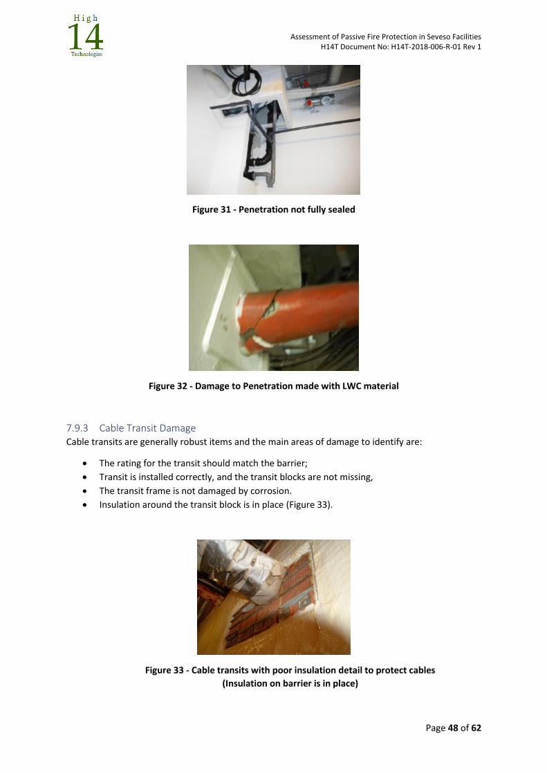
Assessment of Passive Fire Protection in Seveso Facilities H14T Document No: H14T-2018-006-R-01 Rev 1
Page 48 of 62
Figure 31 - Penetration not fully sealed
Figure 32 - Damage to Penetration made with LWC material
7.9.3 Cable Transit Damage Cable transits are generally robust items and the main areas of damage to identify are:
The rating for the transit should match the barrier;
Transit is installed correctly, and the transit blocks are not missing,
The transit frame is not damaged by corrosion.
Insulation around the transit block is in place (Figure 33).
Figure 33 - Cable transits with poor insulation detail to protect cables
(Insulation on barrier is in place)
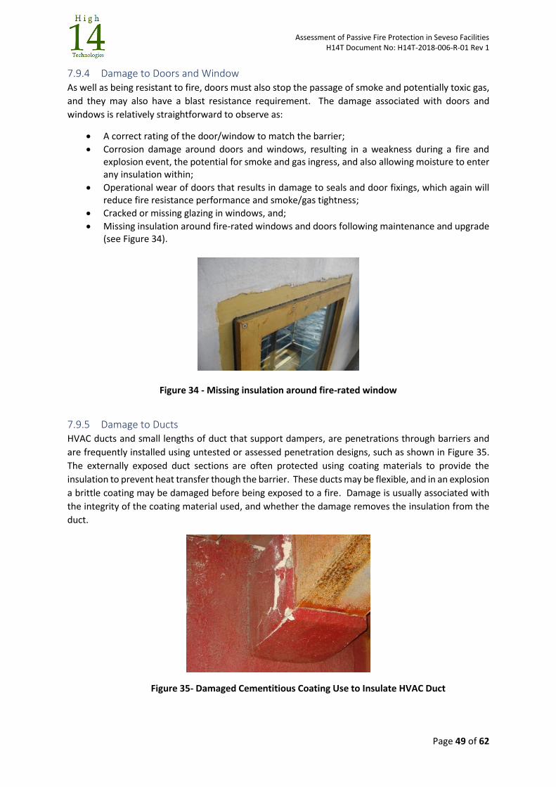
Assessment of Passive Fire Protection in Seveso Facilities H14T Document No: H14T-2018-006-R-01 Rev 1
Page 49 of 62
7.9.4 Damage to Doors and Window As well as being resistant to fire, doors must also stop the passage of smoke and potentially toxic gas,
and they may also have a blast resistance requirement. The damage associated with doors and
windows is relatively straightforward to observe as:
A correct rating of the door/window to match the barrier;
Corrosion damage around doors and windows, resulting in a weakness during a fire and explosion event, the potential for smoke and gas ingress, and also allowing moisture to enter any insulation within;
Operational wear of doors that results in damage to seals and door fixings, which again will reduce fire resistance performance and smoke/gas tightness;
Cracked or missing glazing in windows, and;
Missing insulation around fire-rated windows and doors following maintenance and upgrade (see Figure 34).
Figure 34 - Missing insulation around fire-rated window
7.9.5 Damage to Ducts HVAC ducts and small lengths of duct that support dampers, are penetrations through barriers and
are frequently installed using untested or assessed penetration designs, such as shown in Figure 35.
The externally exposed duct sections are often protected using coating materials to provide the
insulation to prevent heat transfer though the barrier. These ducts may be flexible, and in an explosion
a brittle coating may be damaged before being exposed to a fire. Damage is usually associated with
the integrity of the coating material used, and whether the damage removes the insulation from the
duct.
Figure 35- Damaged Cementitious Coating Use to Insulate HVAC Duct
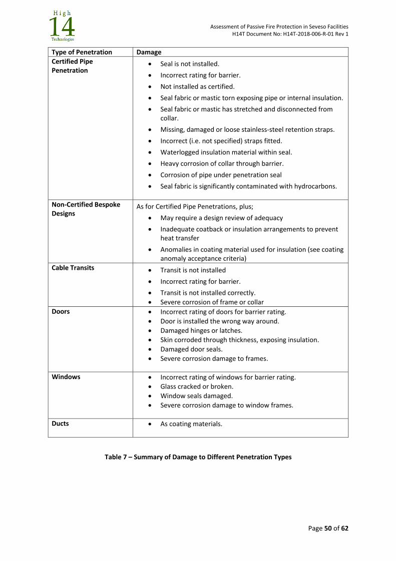
Assessment of Passive Fire Protection in Seveso Facilities H14T Document No: H14T-2018-006-R-01 Rev 1
Page 50 of 62
Type of Penetration Damage
Certified Pipe Penetration
Seal is not installed.
Incorrect rating for barrier.
Not installed as certified.
Seal fabric or mastic torn exposing pipe or internal insulation.
Seal fabric or mastic has stretched and disconnected from collar.
Missing, damaged or loose stainless-steel retention straps.
Incorrect (i.e. not specified) straps fitted.
Waterlogged insulation material within seal.
Heavy corrosion of collar through barrier.
Corrosion of pipe under penetration seal
Seal fabric is significantly contaminated with hydrocarbons.
Non-Certified Bespoke Designs
As for Certified Pipe Penetrations, plus;
May require a design review of adequacy
Inadequate coatback or insulation arrangements to prevent heat transfer
Anomalies in coating material used for insulation (see coating anomaly acceptance criteria)
Cable Transits Transit is not installed
Incorrect rating for barrier.
Transit is not installed correctly.
Severe corrosion of frame or collar
Doors Incorrect rating of doors for barrier rating.
Door is installed the wrong way around.
Damaged hinges or latches.
Skin corroded through thickness, exposing insulation.
Damaged door seals.
Severe corrosion damage to frames.
Windows Incorrect rating of windows for barrier rating.
Glass cracked or broken.
Window seals damaged.
Severe corrosion damage to window frames.
Ducts As coating materials.
Table 7 – Summary of Damage to Different Penetration Types
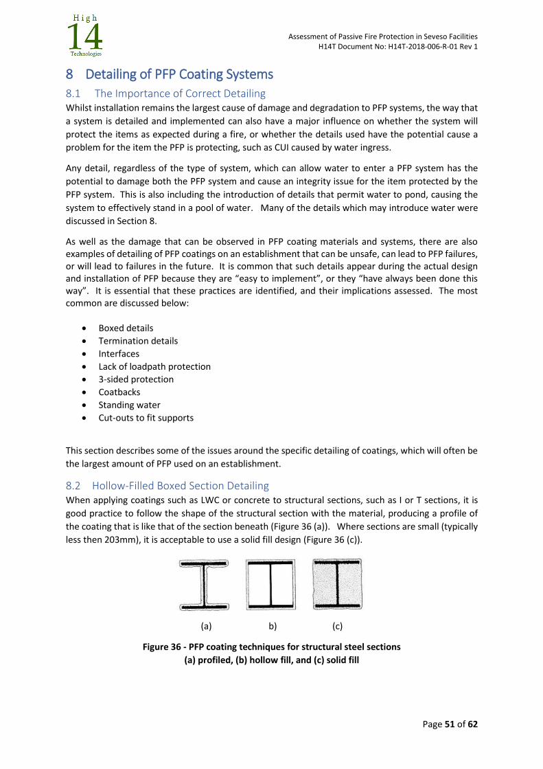
Assessment of Passive Fire Protection in Seveso Facilities H14T Document No: H14T-2018-006-R-01 Rev 1
Page 51 of 62
8 Detailing of PFP Coating Systems
8.1 The Importance of Correct Detailing Whilst installation remains the largest cause of damage and degradation to PFP systems, the way that
a system is detailed and implemented can also have a major influence on whether the system will
protect the items as expected during a fire, or whether the details used have the potential cause a
problem for the item the PFP is protecting, such as CUI caused by water ingress.
Any detail, regardless of the type of system, which can allow water to enter a PFP system has the
potential to damage both the PFP system and cause an integrity issue for the item protected by the
PFP system. This is also including the introduction of details that permit water to pond, causing the
system to effectively stand in a pool of water. Many of the details which may introduce water were
discussed in Section 8.
As well as the damage that can be observed in PFP coating materials and systems, there are also examples of detailing of PFP coatings on an establishment that can be unsafe, can lead to PFP failures, or will lead to failures in the future. It is common that such details appear during the actual design and installation of PFP because they are “easy to implement”, or they “have always been done this way”. It is essential that these practices are identified, and their implications assessed. The most common are discussed below:
Boxed details
Termination details
Interfaces
Lack of loadpath protection
3-sided protection
Coatbacks
Standing water
Cut-outs to fit supports
This section describes some of the issues around the specific detailing of coatings, which will often be
the largest amount of PFP used on an establishment.
8.2 Hollow-Filled Boxed Section Detailing When applying coatings such as LWC or concrete to structural sections, such as I or T sections, it is
good practice to follow the shape of the structural section with the material, producing a profile of
the coating that is like that of the section beneath (Figure 36 (a)). Where sections are small (typically
less then 203mm), it is acceptable to use a solid fill design (Figure 36 (c)).
(a) b) (c)
Figure 36 - PFP coating techniques for structural steel sections
(a) profiled, (b) hollow fill, and (c) solid fill
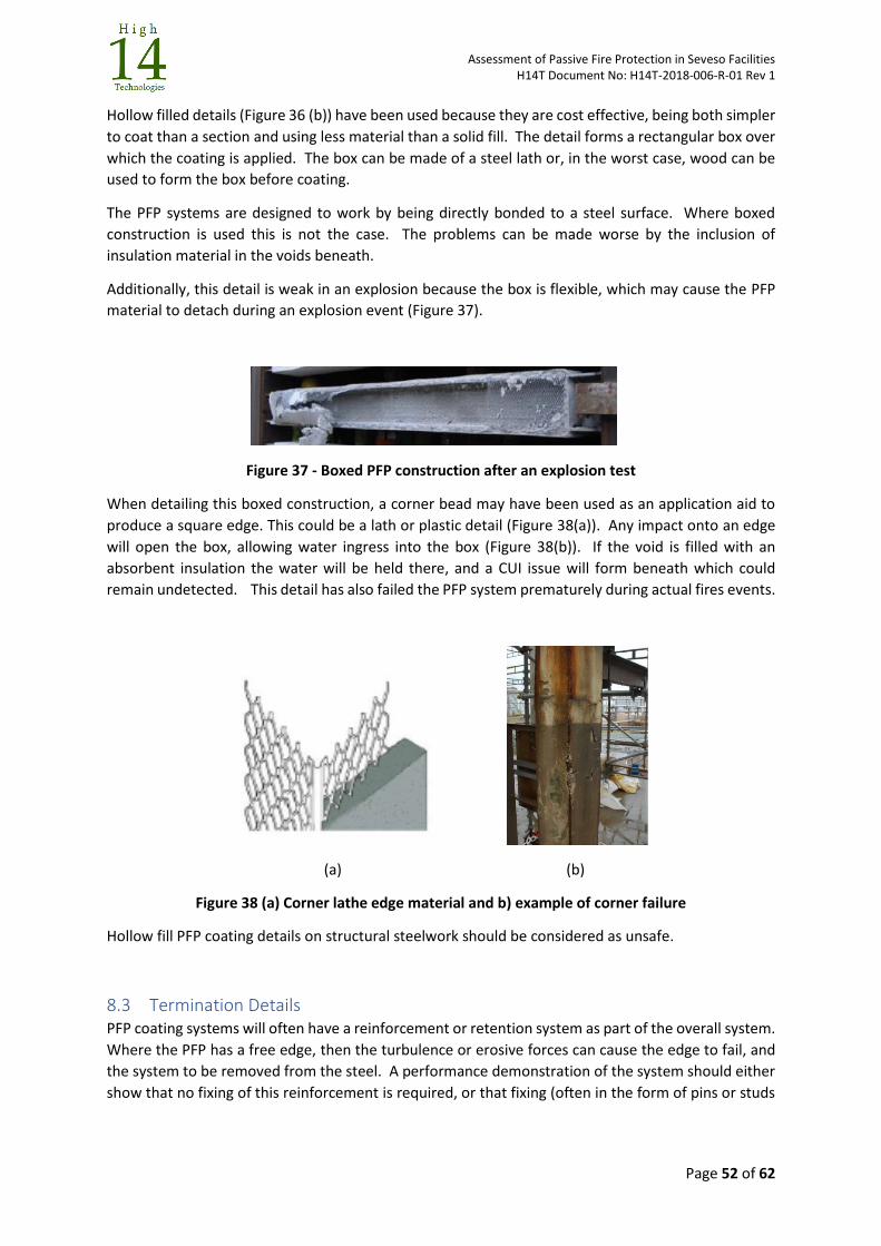
Assessment of Passive Fire Protection in Seveso Facilities H14T Document No: H14T-2018-006-R-01 Rev 1
Page 52 of 62
Hollow filled details (Figure 36 (b)) have been used because they are cost effective, being both simpler
to coat than a section and using less material than a solid fill. The detail forms a rectangular box over
which the coating is applied. The box can be made of a steel lath or, in the worst case, wood can be
used to form the box before coating.
The PFP systems are designed to work by being directly bonded to a steel surface. Where boxed
construction is used this is not the case. The problems can be made worse by the inclusion of
insulation material in the voids beneath.
Additionally, this detail is weak in an explosion because the box is flexible, which may cause the PFP
material to detach during an explosion event (Figure 37).
Figure 37 - Boxed PFP construction after an explosion test
When detailing this boxed construction, a corner bead may have been used as an application aid to
produce a square edge. This could be a lath or plastic detail (Figure 38(a)). Any impact onto an edge
will open the box, allowing water ingress into the box (Figure 38(b)). If the void is filled with an
absorbent insulation the water will be held there, and a CUI issue will form beneath which could
remain undetected. This detail has also failed the PFP system prematurely during actual fires events.
(a) (b)
Figure 38 (a) Corner lathe edge material and b) example of corner failure
Hollow fill PFP coating details on structural steelwork should be considered as unsafe.
8.3 Termination Details PFP coating systems will often have a reinforcement or retention system as part of the overall system.
Where the PFP has a free edge, then the turbulence or erosive forces can cause the edge to fail, and
the system to be removed from the steel. A performance demonstration of the system should either
show that no fixing of this reinforcement is required, or that fixing (often in the form of pins or studs
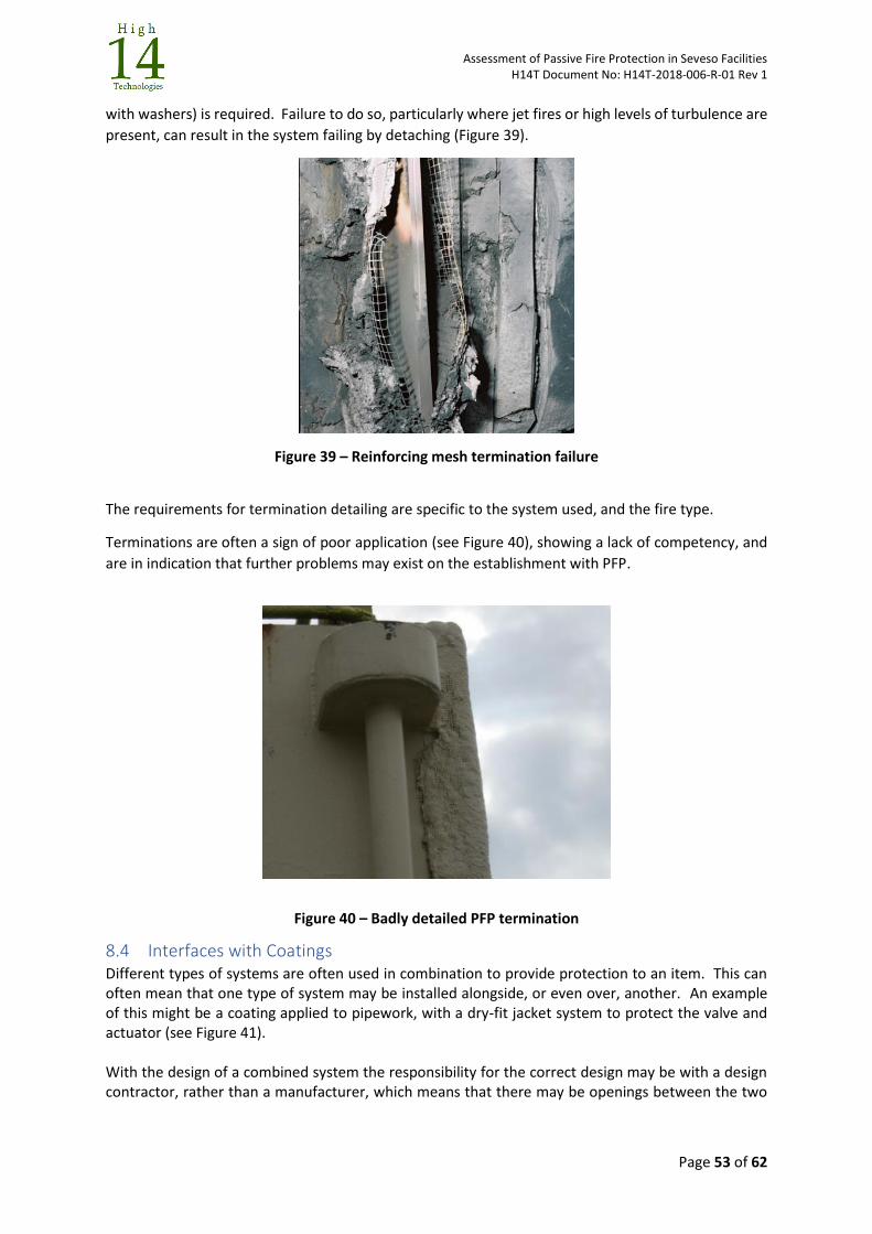
Assessment of Passive Fire Protection in Seveso Facilities H14T Document No: H14T-2018-006-R-01 Rev 1
Page 53 of 62
with washers) is required. Failure to do so, particularly where jet fires or high levels of turbulence are
present, can result in the system failing by detaching (Figure 39).
Figure 39 – Reinforcing mesh termination failure
The requirements for termination detailing are specific to the system used, and the fire type.
Terminations are often a sign of poor application (see Figure 40), showing a lack of competency, and
are in indication that further problems may exist on the establishment with PFP.
Figure 40 – Badly detailed PFP termination
8.4 Interfaces with Coatings Different types of systems are often used in combination to provide protection to an item. This can often mean that one type of system may be installed alongside, or even over, another. An example of this might be a coating applied to pipework, with a dry-fit jacket system to protect the valve and actuator (see Figure 41). With the design of a combined system the responsibility for the correct design may be with a design contractor, rather than a manufacturer, which means that there may be openings between the two
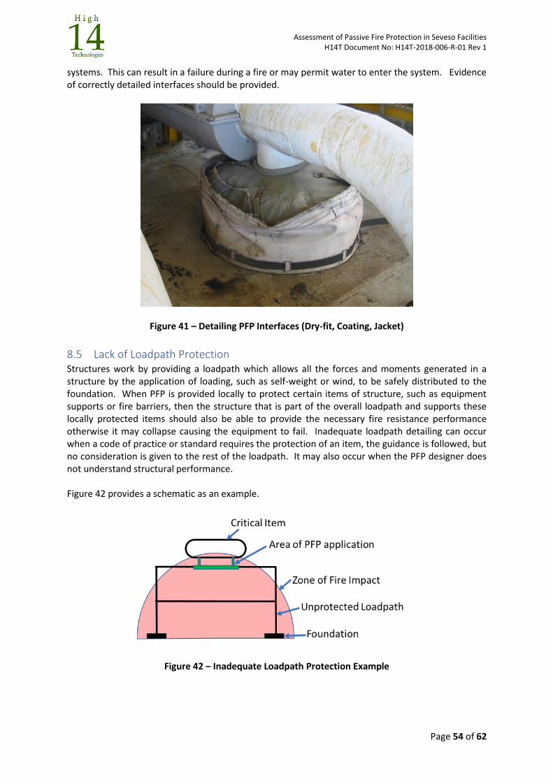
Assessment of Passive Fire Protection in Seveso Facilities H14T Document No: H14T-2018-006-R-01 Rev 1
Page 54 of 62
systems. This can result in a failure during a fire or may permit water to enter the system. Evidence of correctly detailed interfaces should be provided.
Figure 41 – Detailing PFP Interfaces (Dry-fit, Coating, Jacket)
8.5 Lack of Loadpath Protection Structures work by providing a loadpath which allows all the forces and moments generated in a structure by the application of loading, such as self-weight or wind, to be safely distributed to the foundation. When PFP is provided locally to protect certain items of structure, such as equipment supports or fire barriers, then the structure that is part of the overall loadpath and supports these locally protected items should also be able to provide the necessary fire resistance performance otherwise it may collapse causing the equipment to fail. Inadequate loadpath detailing can occur when a code of practice or standard requires the protection of an item, the guidance is followed, but no consideration is given to the rest of the loadpath. It may also occur when the PFP designer does not understand structural performance. Figure 42 provides a schematic as an example.
Figure 42 – Inadequate Loadpath Protection Example
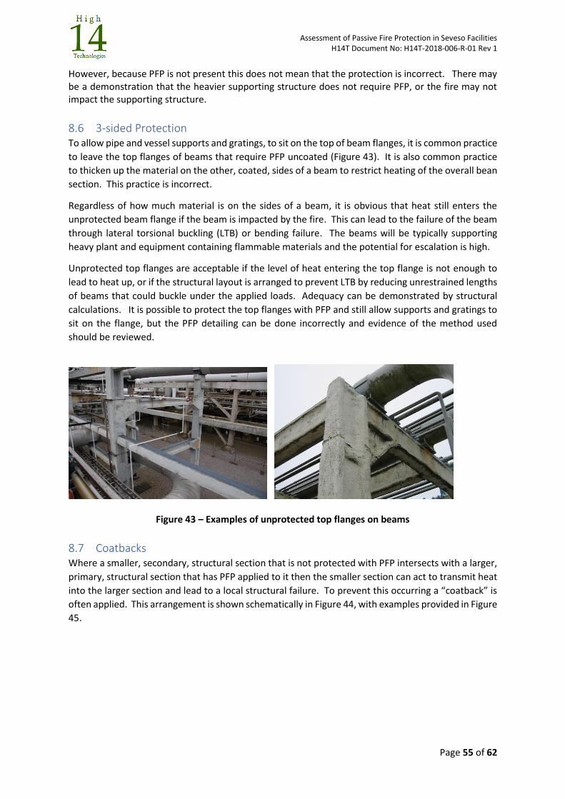
Assessment of Passive Fire Protection in Seveso Facilities H14T Document No: H14T-2018-006-R-01 Rev 1
Page 55 of 62
However, because PFP is not present this does not mean that the protection is incorrect. There may be a demonstration that the heavier supporting structure does not require PFP, or the fire may not impact the supporting structure.
8.6 3-sided Protection To allow pipe and vessel supports and gratings, to sit on the top of beam flanges, it is common practice
to leave the top flanges of beams that require PFP uncoated (Figure 43). It is also common practice
to thicken up the material on the other, coated, sides of a beam to restrict heating of the overall bean
section. This practice is incorrect.
Regardless of how much material is on the sides of a beam, it is obvious that heat still enters the
unprotected beam flange if the beam is impacted by the fire. This can lead to the failure of the beam
through lateral torsional buckling (LTB) or bending failure. The beams will be typically supporting
heavy plant and equipment containing flammable materials and the potential for escalation is high.
Unprotected top flanges are acceptable if the level of heat entering the top flange is not enough to
lead to heat up, or if the structural layout is arranged to prevent LTB by reducing unrestrained lengths
of beams that could buckle under the applied loads. Adequacy can be demonstrated by structural
calculations. It is possible to protect the top flanges with PFP and still allow supports and gratings to
sit on the flange, but the PFP detailing can be done incorrectly and evidence of the method used
should be reviewed.
Figure 43 – Examples of unprotected top flanges on beams
8.7 Coatbacks Where a smaller, secondary, structural section that is not protected with PFP intersects with a larger,
primary, structural section that has PFP applied to it then the smaller section can act to transmit heat
into the larger section and lead to a local structural failure. To prevent this occurring a “coatback” is
often applied. This arrangement is shown schematically in Figure 44, with examples provided in Figure
45.
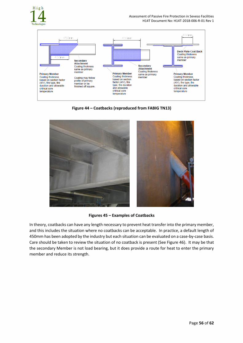
Assessment of Passive Fire Protection in Seveso Facilities H14T Document No: H14T-2018-006-R-01 Rev 1
Page 56 of 62
Figure 44 – Coatbacks (reproduced from FABIG TN13)
Figures 45 – Examples of Coatbacks
In theory, coatbacks can have any length necessary to prevent heat transfer into the primary member,
and this includes the situation where no coatbacks can be acceptable. In practice, a default length of
450mm has been adopted by the industry but each situation can be evaluated on a case-by-case basis.
Care should be taken to review the situation of no coatback is present (See Figure 46). It may be that
the secondary Member is not load bearing, but it does provide a route for heat to enter the primary
member and reduce its strength.
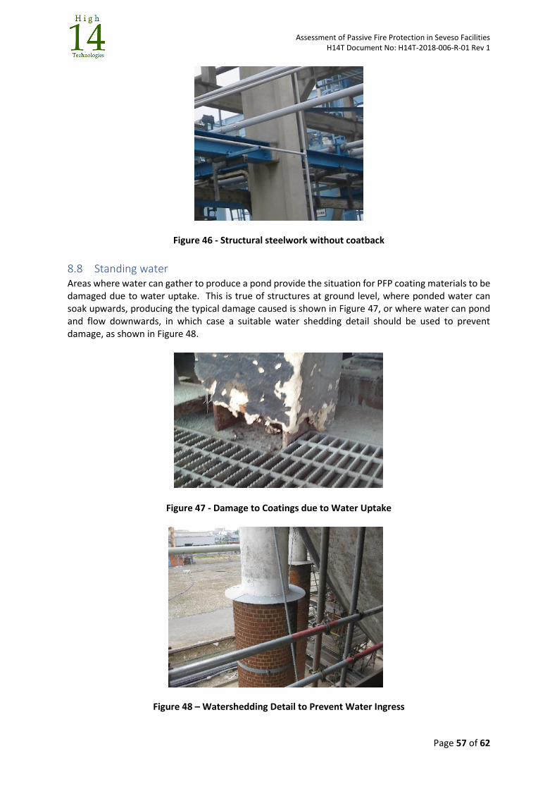
Assessment of Passive Fire Protection in Seveso Facilities H14T Document No: H14T-2018-006-R-01 Rev 1
Page 57 of 62
Figure 46 - Structural steelwork without coatback
8.8 Standing water Areas where water can gather to produce a pond provide the situation for PFP coating materials to be damaged due to water uptake. This is true of structures at ground level, where ponded water can soak upwards, producing the typical damage caused is shown in Figure 47, or where water can pond and flow downwards, in which case a suitable water shedding detail should be used to prevent damage, as shown in Figure 48.
Figure 47 - Damage to Coatings due to Water Uptake
Figure 48 – Watershedding Detail to Prevent Water Ingress
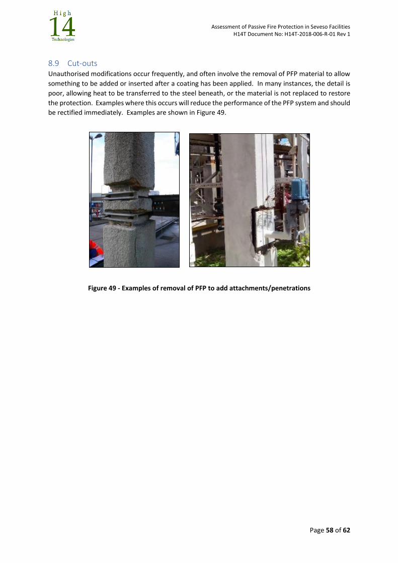
Assessment of Passive Fire Protection in Seveso Facilities H14T Document No: H14T-2018-006-R-01 Rev 1
Page 58 of 62
8.9 Cut-outs Unauthorised modifications occur frequently, and often involve the removal of PFP material to allow
something to be added or inserted after a coating has been applied. In many instances, the detail is
poor, allowing heat to be transferred to the steel beneath, or the material is not replaced to restore
the protection. Examples where this occurs will reduce the performance of the PFP system and should
be rectified immediately. Examples are shown in Figure 49.
Figure 49 - Examples of removal of PFP to add attachments/penetrations
Assessment of Passive Fire Protection in Seveso Facilities H14T Document No: H14T-2018-006-R-01 Rev 1
Page 59 of 62
9 Integrity Management – Inspection and Assessment
9.1 Integrity Management Process
Like any other system that is installed for the protection of people or the environment, PFP should be managed through its life to ensure that it performs as required during an emergency. The primary elements of an integrity management process for PFP are:
Clarity on Roles and Responsibilities
Processes and Procedures
Documentation and Record keeping
Management of Change
Inspection
Assessment
Repair Some standards refer to the need for integrity management of PFP, and all effective Regulations also require safety systems to be inspected and maintained, but there is very little guidance on how to actually do this, or that provide acceptance criteria for damage assessment. See, for example, API2218 Section 9, ISO 13702 Section 15, or FABIG TN13 Section 6 which all note the need.
9.2 Roles and Responsibilities Although the steps that are noted above are typical for any establishment in which PFP is managed as
a safety system, the roles and responsibilities can vary from establishment to establishment. In some
establishments the overall system of PFP could be managed by the Civil Engineering department, by
the Safety and Loss Prevention Department, by the Mechanical Engineering Department, by the
integrity management group, or by materials specialists. It may be that departments or individuals
have different roles in the overall process, but there should be someone with overall responsibility for
PFP on the establishment
Regardless of who manages PFP, the arrangements for managing PFP on the establishment should be
explained within the Safety Management System, and the roles and responsibilities of individuals
should also be included.
They, and the organisation that supports them in ensuring the integrity of the PFP, should have the
necessary awareness and competency to apply the establishment procedures and processes.
9.3 Processes and Procedures It would be expected that an establishment that uses PFP to manage its fire risks would have:
A fire protection philosophy for the establishment that sets out the company’s approach to the
provision of fire protection for the establishment, establishing why fire protection is needed. This will
detail the Regulations that are to be satisfied and what the fire protection needs to achieve in terms
of managing risks. For some establishments, this document may well be a company fire protection
philosophy, rather than an establishment specific document. This document may well consider the
use of active and passive fire protection, along with firefighting.
A passive fire protection strategy can again be an establishment or company document and will more
detailed than a philosophy document. If the establishment defines its PFP based on a prescriptive
approach it will to identify what should be protected, for how long, using what systems. If the process
Assessment of Passive Fire Protection in Seveso Facilities H14T Document No: H14T-2018-006-R-01 Rev 1
Page 60 of 62
is more risk-based, it can lay out the risk assessment processes and procedures that should be used
but may also again identify certain systems that should be used on the establishment.
An Integrity management strategy that describes the process by which PFP is inspected and
maintained to ensure that the philosophy, strategy and ultimately the SMS is satisfied. The integrity
management of PFP requires a consideration of:
How all documents for PFP are managed.
What is inspected, what methods are used, how frequently it is inspected, recording of the
inspection and actions on finding damage or defects, and the necessary qualification of
inspectors to undertake these tasks. This may be a separate inspection document.
How any defects or damage is evaluated to establish if the performance of the PFP is reduced.
The risk assessment processes to evaluate the effect of reduced PFP performance on the
establishment
The process for change management, which should ensure that the person who is responsible
for PFP reviews any changes to the establishment and determines if the PFP remains fit-for-
purpose, or whether the change is large enough to require a re-assessment of the PFP.
The repair processes for PFP systems that should be followed.
9.4 Note on Documentation and Record Keeping A record of the installed PFP systems should be available.
In many older establishments it is often difficult to establish the make and type of material or system
that has been installed, and that can often mean that the original specification of performance of the
system is unknown, or the type of material may not be suitable for the actual fire threats present.
Where original materials specifications or Manufacturers information is available then this should be
preserved. The best form of preservation of PFP records is the use of a PFP Register for the
establishment, which records details of where the PFP systems are, what they are, and their actual
specification. The PFP Register is particularly useful when evaluating PFP systems following a change
to the facility.
9.5 Note on Inspection of PFP Systems Written guidance should be available for the inspection of PFP systems. This should explain:
An inspection schedule that gives the frequency with which the different PFP systems should
be inspected.
Written task descriptions for the different PFP systems, describing how each system should
be inspected. This should include non-destructive and destructive test methods to be used,
and actions for the case when destructive testing takes place.
What must happen when PFP is removed to allow the inspection of an item beneath, such as
for a CUI inspection.
What inspection information should be recorded and reported to allow a correct assessment
of fitness-for-purpose.
The required competency of the inspectors undertaking the inspections.
Section 8 of this document contains details of the types of defects that must be inspected for in PFP
systems.
Assessment of Passive Fire Protection in Seveso Facilities H14T Document No: H14T-2018-006-R-01 Rev 1
Page 61 of 62
9.6 Note on Assessment of PFP Systems Following Inspection Following inspection of PFP systems and reporting of the results, any damage that is found must be
evaluated to establish whether the PFP system remains fit-for-purpose. A procedure or process for
this should be available, and it requires two key elements:
Acceptance criteria, or some method or explanation, against which any damage is assessed to
determine whether it results in a reduced performance of the PFP. Some companies have
established criteria to understand the importance of the damage, whilst others will use a
process that automatically undertakes a repair of the PFP if any damage is found. There are
no major published sources of data on damage.
An assessment process that considers the level of damage that is observed, the likely
reduction in fire resistance performance, and the consequences of that reduction on the
safety of humans and the environment. Actions are then determined based on the outcome
of this assessment. This may be a risk-based assessment process.
There is no detailed published guidance on acceptance criteria for damage in PFP systems. The UK
Health and Safety Executive has published an information sheet (“Advice on acceptance criteria for
damaged Passive Fire Protection (PFP) Coatings. Offshore Information Sheet No. 12/2007”.) which
gives some simple guidelines that consider coatings only. Some testing work on the performance of
cementitious and epoxy coatings has also been undertaken and reported (“Joint Industry Project on
Acceptance Criteria for Damaged Passive Fire Protection Coatings. MMI Engineering Report
MMU013–P2-R-01. 2005”).
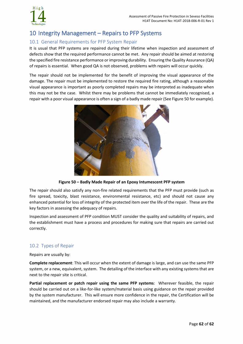
Assessment of Passive Fire Protection in Seveso Facilities H14T Document No: H14T-2018-006-R-01 Rev 1
Page 62 of 62
10 Integrity Management – Repairs to PFP Systems
10.1 General Requirements for PFP System Repair It is usual that PFP systems are repaired during their lifetime when inspection and assessment of
defects show that the required performance cannot be met. Any repair should be aimed at restoring
the specified fire resistance performance or improving durability. Ensuring the Quality Assurance (QA)
of repairs is essential. When good QA is not observed, problems with repairs will occur quickly.
The repair should not be implemented for the benefit of improving the visual appearance of the
damage. The repair must be implemented to restore the required fire rating, although a reasonable
visual appearance is important as poorly completed repairs may be interpreted as inadequate when
this may not be the case. Whilst there may be problems that cannot be immediately recognised, a
repair with a poor visual appearance is often a sign of a badly made repair (See Figure 50 for example).
Figure 50 – Badly Made Repair of an Epoxy Intumescent PFP system
The repair should also satisfy any non-fire related requirements that the PFP must provide (such as
fire spread, toxicity, blast resistance, environmental resistance, etc) and should not cause any
enhanced potential for loss of integrity of the protected item over the life of the repair. These are the
key factors in assessing the adequacy of repairs.
Inspection and assessment of PFP condition MUST consider the quality and suitability of repairs, and
the establishment must have a process and procedures for making sure that repairs are carried out
correctly.
10.2 Types of Repair
Repairs are usually by:
Complete replacement: This will occur when the extent of damage is large, and can use the same PFP
system, or a new, equivalent, system. The detailing of the interface with any existing systems that are
next to the repair site is critical.
Partial replacement or patch repair using the same PFP systems: Wherever feasible, the repair
should be carried out on a like-for-like system/material basis using guidance on the repair provided
by the system manufacturer. This will ensure more confidence in the repair, the Certification will be
maintained, and the manufacturer endorsed repair may also include a warranty.
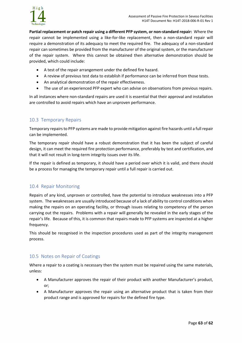
Assessment of Passive Fire Protection in Seveso Facilities H14T Document No: H14T-2018-006-R-01 Rev 1
Page 63 of 62
Partial replacement or patch repair using a different PFP system, or non-standard repair: Where the
repair cannot be implemented using a like-for-like replacement, then a non-standard repair will
require a demonstration of its adequacy to meet the required fire. The adequacy of a non-standard
repair can sometimes be provided from the manufacturer of the original system, or the manufacturer
of the repair system. Where this cannot be obtained then alternative demonstration should be
provided, which could include:
A test of the repair arrangement under the defined fire hazard.
A review of previous test data to establish if performance can be inferred from those tests.
An analytical demonstration of the repair effectiveness.
The use of an experienced PFP expert who can advise on observations from previous repairs.
In all instances where non-standard repairs are used it is essential that their approval and installation
are controlled to avoid repairs which have an unproven performance.
10.3 Temporary Repairs
Temporary repairs to PFP systems are made to provide mitigation against fire hazards until a full repair
can be implemented.
The temporary repair should have a robust demonstration that it has been the subject of careful
design, it can meet the required fire protection performance, preferably by test and certification, and
that it will not result in long-term integrity issues over its life.
If the repair is defined as temporary, it should have a period over which it is valid, and there should
be a process for managing the temporary repair until a full repair is carried out.
10.4 Repair Monitoring
Repairs of any kind, unproven or controlled, have the potential to introduce weaknesses into a PFP
system. The weaknesses are usually introduced because of a lack of ability to control conditions when
making the repairs on an operating facility, or through issues relating to competency of the person
carrying out the repairs. Problems with a repair will generally be revealed in the early stages of the
repair’s life. Because of this, it is common that repairs made to PFP systems are inspected at a higher
frequency.
This should be recognised in the inspection procedures used as part of the integrity management
process.
10.5 Notes on Repair of Coatings
Where a repair to a coating is necessary then the system must be repaired using the same materials,
unless:
A Manufacturer approves the repair of their product with another Manufacturer’s product,
or;
A Manufacturer approves the repair using an alternative product that is taken from their
product range and is approved for repairs for the defined fire type.
Assessment of Passive Fire Protection in Seveso Facilities H14T Document No: H14T-2018-006-R-01 Rev 1
Page 64 of 62
An example of an approved repair using dissimilar coating materials (LWC repaired with an epoxy
intumescent) is shown in Figure 51. This repair has been detailed and tested by a manufacturer and
was economical to implement.
Figure 51 – Repair of LWC material with an epoxy intumescent.
Epoxy intumescent and subliming materials are reactive, and each product reacts in a unique way. In
addition, arrangements for reinforcement vary between products. A mismatched repair using mixed
epoxy-based products can result in the repair failing prematurely during a fire.
All coating Manufacturers provide guidelines for repairs that deal with factors such as the amount of
material to be removed, substrate preparation, reinforcement overlap, etc. and this guidance should
be followed.
10.6 Notes on Repairs to Dry-fit systems
The most common form of damage to dry-fit systems is due to the incorrect replacement of the system
after it has been removed for maintenance activities. Assuming the PFP materials that make up the
dry-fit system are in an acceptable condition, then the repair should involve re-installing the system
correctly. When undertaking this activity, connections and retention systems should be replaced using
new components if they show signs of damage. Any seals which ensure water or gas tightness should
also be replaced.
Because dry-fit systems are manufactured from an assembly of components, then it is possible to
replace individual components if they are damaged, rather than the complete system. A like-for-like
replacement of any component is preferable, using components from the original Manufacturer.
On older dry-fit systems, where original components are no longer available, it is possible to use
alternative components that provide the same, or a higher, level of protection. This will generally be
achieved using a similar material but confirmation of this should have been sought from the
component Manufacturer or a PFP specialist. Care is required to ensure that the component is
correctly integrated into the system.
Where a material such as a coating or composite material is part of a dry-fit system, repairs to the
coatings can be undertaken using the recommended repair procedures for these materials.
Assessment of Passive Fire Protection in Seveso Facilities H14T Document No: H14T-2018-006-R-01 Rev 1
Page 65 of 62
10.7 Notes on Repairs to Wet-Applied Systems
The repair of wet-applied systems is more complex than repairs to dry-fit systems. A dry-fit system is
a collection of components, often allowing easy removal and replacement of individual damaged
components, whereas wet-applied systems are continuous systems that often bonded to the
substrate and/or each other. In a similar way to coatings, any repairs must restore that overall
integrity. Careful control of conditions during repair is required due to the combination of materials
that make up the system.
For some systems, such as those involving bonded composites, the Manufacturer should be engaged
to undertake the repair as the materials and repairs are specialised.
When repairing a complete system for which no repair guideline exists, a procedure should be
developed with the original system designer or Manufacturer to ensure that the mechanical strength,
fire and blast resistance and integrity of the system are restored to the original condition.
Repair guidelines for coatings apply to the repair of the outer skin of wet applied systems where these
subliming or epoxy intumescent coating products are used.
Like-for-like replacement of materials within the system is essential because the wet applied systems
have been developed and tested as a combined system. The Certification and test reports that form
the demonstration of acceptance relate to that specific combination of components and materials.
For these systems, general repair procedures are not applicable, and repairs should only be done with
agreement and guidance from the system designer or Manufacturer.
10.8 Notes on Repairs to Barriers Systems
Damage to metallic and concrete based barrier systems may well be observed during structural
inspections and repairs should be implemented as would normally be undertaken for these items.
Metallic and concrete barriers can be repaired using patches, often based on composite materials.
Patch repairs can have adequate strength to restore integrity and water tightness, but they must be
proven to be effective in fires, preferably through a fire test.
Repairs to other types of barriers will either involve restoring any insulation material, along with
retention system, or restoring the integrity of any structural elements of the barrier that may be
constructed from composite materials. In these instances, specialist advice may be required to ensure
that the repair is undertaken correctly.
Barriers will be subjected to high levels of thermal expansion and strain during a fire. Any repair must
be proven to be able to resist those strains. Repairs made with dissimilar materials may experience
differential levels of thermal expansion between the two components, resulting in enhanced strains
at any interface. Proof of performance of patch repairs to barriers under fire loading is essential
because the repairs may only have been developed to restore integrity
10.9 Notes on Repairs of Penetrations through Barriers
Repairs of penetrations through barriers can have significant variability due to the many forms of
penetrations, and the often ad-hoc nature of the penetration.
Where the damaged penetration is a certified penetration, then the repair should involve:
Making good of any corrosion or damage to the barrier around the penetration location,
including any collars required to install the penetration,
Assessment of Passive Fire Protection in Seveso Facilities H14T Document No: H14T-2018-006-R-01 Rev 1
Page 66 of 62
Making good any corrosion or damage to the pipe or other item that penetrates the barrier.
The replacement of any damaged or missing components of the penetration.
Certified barriers include pipe and cable penetrations, doors, windows, ducts, etc. that have been
tested by the Manufacturer and have a fire or explosion rating associated with them.
Where the penetration is an ad-hoc penetration seal used to restrict heat transfer when a pipe or duct
penetrates a barrier, and whose insulation is provided externally using a coating material such as an
LWC or epoxy intumescent, then the repairs of damage to the external coating should follow the
guidelines provided in Section 10.5.
Where the penetration has internal insulation such as MMMF material, or for fire-resistant mastic
systems, then if the damage is associated with this insulation or mastic, then the repair should:
Make good any corrosion or damage to the barrier around the penetration location, including any collars required to install the penetration,
Make good any corrosion or damage to the pipe or other item that penetrates the barrier
Replace the damaged insulation or mastic material.
Note: It is preferred that an ad-hoc penetration seal is removed and replaced by a penetration
arrangement that has been tested and certified.
Assessment of Passive Fire Protection in Seveso Facilities H14T Document No: H14T-2018-006-R-01 Rev 1
Page 67 of 62
11 Assessing Ageing PFP on Seveso Establishments
11.1 The Assessment Process To assess the adequacy of ageing PFP in Seveso establishments there are 3 checks to be made
1) A documentation review. This assesses whether there is documentation in place within the
Safety Management System and presented in the Safety Report, that satisfies Seveso III
Annexe III. It considers the management of PFP and shows that the correct processes needed
for effective design and integrity management are in-place and are being applied.
2) A design and specification review. This assesses whether the PFP that is installed on the
establishment been selected and implemented correctly so that it provides the necessary
mitigation against the fire scenarios that are present.
3) A review of whether the integrity of PFP is being managed correctly. This reviews the
condition of the installed PFP and determines whether it is still fit-for-purpose or whether it
is damaged so that its effectiveness is reduced.
Checklists are provided for each of these three main activities. The checklists refer to the Seveso
articles that are being assessed, and the sources within this document where guidance and
explanation may be found.
Note: Depending on the time available for an inspection, Checklists 2 and 3 could be applied to a
selected system as a sampling check to establish if the processes and methods in place for the
establishment are acceptable.
11.2 Checklist 1 – Documentation Review
Checklist 1 is aimed at ensuring compliance with Seveso III Annex III, which covers information referred
to in Article 8(5) and Article 10 on the safety management system (SMS) and the organisation of the
establishment with a view to the prevention of major accidents.
The checklist covers the processes and procedures within the SMS and the Safety Report that are
relevant to PFP to the specification and integrity management of PFP to maintain it as a safety device.
When gathering information prior to any inspections of the PFP systems the following detailed
information may be available during documentation reviews should be collected to assist in that
inspection:
The fire scenarios which affect the item that is protected
The record of the PFP system held by the establishment, including the PFP performance
specification
Details of the installed system (make, drawings, certifications, test reports, etc)
Inspection and repair records
11.3 Checklist 2 – A Design and Specification Review
This checklist is used to assess whether any PFP system that has been installed to protect a critical
item has the correct specification and demonstration so that it can provide the required performance.
PFP systems are classed as:
Applied Coatings
Dry-Fit Systems
Assessment of Passive Fire Protection in Seveso Facilities H14T Document No: H14T-2018-006-R-01 Rev 1
Page 68 of 62
Wet-Applied Systems
Pipe Penetrations and Cable Transits
Barriers
Penetrations through barriers
Others such as brick or earth
The checklist should be applied to any of these generic PFP systems when inspected to ensure that its
fundamental suitability is adequate, regardless of condition. Detail supporting the checklist is found
throughout this document.
11.4 Checklist 3 – A Review that the Integrity of the PFP System Being Managed
Correctly
This checklist is used to assess whether a correctly specified and installed PFP system continues to
provide the required fire resistance performance. This requires an evaluation of any damage that
might be visible and an assessment of how severe that damage can be in terms of reducing the fire
resistance capability. The establishment Safety Management System should ensure that the condition
is acceptable, and this check on condition will verify that this is the case.
Again, the checklist can be applied to any of the generic PFP systems when inspected to assess
whether the condition of the PFP system will affect the required fire resistance performance. The
checklist refers to simple tables which contain details of damage and severity of damage for each PFP
system type. These are presented in Appendix C and are supported by guidance provided in Sections
7, 9 and 10 of this document.
IMPORTANT NOTE: The assessment table presented in Appendix C are not failure or assessment
acceptance criteria. They are a tool for screening visible damage which can be used by a Seveso
inspector to identify where damage might reduce the performance of a PFP system. They are based
on experience, rather than proven quantified, approaches.

Assessment of Passive Fire Protection in Seveso Facilities H14T Document No: H14T-2018-006-R-01 Rev 1
Appendices Page 1 of 19
APPENDIX A: PFP AND SEVESO III DIRECTIVE
Assessment of Passive Fire Protection in Seveso Facilities H14T Document No: H14T-2018-006-R-01 Rev 1
Appendices Page 2 of 19
The Seveso Directive
The relevant EU Directive is:
DIRECTIVE 2012/18/EU OF THE EUROPEAN PARLIAMENT AND OF THE COUNCIL of 4 July 2012
on the control of major-accident hazards involving dangerous substances, amending and subsequently
repealing Council Directive 96/82/EC (known in this document as “Seveso III Directive”).
In this section the Articles relevant to PFP are highlighted to ensure that inspections of PFP systems
verify that the requirements of the various Seveso III Articles are met
Article 8: MAPP
Article 8: Operators of an Establishment are required to draw up a written document that sets out the
major-accident prevention policy (MAPP) and to ensure that it is properly implemented. The MAPP
shall be implemented by appropriate means, structures and by a safety management system, in
accordance with Annex III, proportionate to the major-accident hazards, and the complexity of the
organisation or the activities of the establishment.
For lower-tier establishments, the obligation to implement the MAPP may be fulfilled by other
appropriate means, structures and management systems, proportionate to major-accident hazards,
taking into account the principles set out in Annex III.
Relevance to PFP: Clause 8.5 references Annex III, which lays out what would be expected to be seen
in a safety management system which could apply to an upper or lower tier establishment.
With respect to PFP, specific requirements within the SMS should include:
A demonstration that a risk assessment of the major hazards on the establishment has been
undertaken, which should include the fire hazards
The roles and responsibilities of personnel involved in the management of major hazards at all
levels in the organisation, together with the measures taken to raise awareness of the need for
continuous improvement. This must include personnel who have responsibility for specifying,
inspecting and maintaining PFP systems.
The identification and evaluation of major hazards through a systematic risk assessment process,
which will define where residual risk may exist and require the specification and implementation
of PFP to mitigate the hazards
The adoption and implementation of procedures and instructions for safe operation, including
maintenance of plant, processes and equipment. This is particularly relevant to the processes put
in place to monitor, inspect and maintain PFP systems, and should include where PFP has the
potential to lead to corrosion or other integrity issues. This should also include the response should
inadequate PFP be discovered
The inclusion of PFP within the management of change procedure for the establishment to ensure
that the PFP remains an effective mitigation measure.
The inclusion of the role of PFP within any emergency response plans, and the clear communication
of that role.
The inclusion of PFP within any procedures for the ongoing assessment of compliance with the
objectives set by the operator’s MAPP and safety management system, and the mechanisms for
investigation and taking corrective action in case of non-compliance. This may include any safety
Assessment of Passive Fire Protection in Seveso Facilities H14T Document No: H14T-2018-006-R-01 Rev 1
Appendices Page 3 of 19
performance indicators (SPIs) and/or other relevant indicators that are developed for PFP to
support this.
Article 10: Safety Report
Article 10: Operators of an upper-tier establishment must produce a safety report to demonstrate
that a MAPP and a safety management system for implementing it have been put into effect (see
above for the requirements defined by Annex III).
Relevance to PFP: Article 10 references Annex II, which defines the minimum data and information
that should be included in the Safety Report.
The safety report contains much detailed information which describes the facility. However, with
respect to the hazards which arise within the Establishment, and which may require PFP to mitigate
them, the Safety Report should include:
A detailed description of the possible major-accident scenarios, which should include fire and
explosion events on the facility and the causes of those events
Assessment of the extent and severity of the consequences of identified major accidents
including maps, images or, as appropriate, equivalent descriptions, showing areas which are
likely to be affected by such accidents arising from the Establishment. For PFP this will define
the fire zones within which PFP may be required;
With respect to any measures of protection (such as PFP) and intervention to limit the consequences
of a major accident, information presented should include:
A description of the equipment installed in the plant to limit the consequences of major
accidents for human health and environment, which will directly include any PFP
A description of any technical and non-technical measures relevant for the reduction of the
impact of a major accident.
Article 11: Modification
Article 11: Considers the modification of an installation, an establishment or a storage facility. Where
such modifications can have significant consequences for major-accident hazards then the operator
should review, and where necessary update the notification, the MAPP, the safety management
system and the safety report, and inform the competent authority of the details of those updates in
advance of that modification.
Relevance to PFP: When a modification to the Establishment occurs, the existing PFP should be
assessed and where necessary upgraded (or downgraded) to ensure that the revised hazards can still
be mitigated by PFP, as required by the MAPP for the Establishment. This may require new PFP to be
added, existing systems to be upgraded, or a demonstration that PFP that has been specified for an
original set of hazards remains fit for purpose for any different hazards that arise because of the
modification.
Article 20: Inspections
Article 20: Requires that establishments are inspected to a level that is enough for a planned and
systematic examination of the systems being employed at the establishment, whether of a technical,
organisational or managerial nature. The inspections should verify that appropriate measures are in

Assessment of Passive Fire Protection in Seveso Facilities H14T Document No: H14T-2018-006-R-01 Rev 1
Appendices Page 4 of 19
place to prevent major accidents, to limit the on-site and off-site consequences, and to verify that the
data and information contained in the safety report, or any other report submitted, adequately
reflects the conditions in the establishment.
Relevance to PFP: PFP is a technical system and therefore the inspection must verify that the PFP
installed on the establishment is as described in the Safety Report or any other documentation which
supports the MAPP and is in a condition that will enable it to function correctly and provide the correct
level of mitigation.

Assessment of Passive Fire Protection in Seveso Facilities H14T Document No: H14T-2018-006-R-01 Rev 1
Appendices Page 5 of 19
APPENDIX B: ASSESSMENT CHECKLISTS
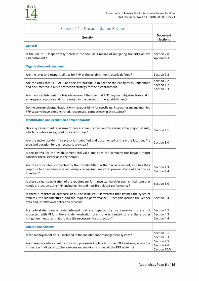
Assessment of Passive Fire Protection in Seveso Facilities H14T Document No: H14T-2018-006-R-01 Rev 1
Appendices Page 6 of 19
Checklist 1 – Documentation Review
Question Document Sections
General
Is the use of PFP specifically noted in the SMS as a means of mitigating fire risks on the establishment?
Section 2.0 Appendix A
Organisation and personnel
Are the roles and responsibilities for PFP at the establishment clearly defined? Section 9.2
Are the roles that PFP, AFP, and the fire brigade in mitigating the fire hazards understood and documented in a fire protection strategy for the establishment?
Section 2.2 Section 4.2 Section 9.3
Are the establishment fire brigade aware of the role that PFP plays in mitigating fires and in emergency response and is this noted in the permit for the establishment?
Do the personnel/organisations with responsibility for specifying, inspecting and maintaining PFP systems have demonstrated, recognised, competency in this subject?
Identification and evaluation of major hazards
Has a systematic risk assessment process been carried out to evaluate the major hazards, which includes a recognised process for fires?
Section 4.1
Are the major accident fire scenarios identified and documented and are the location, fire type and duration for each scenario are clear?
Section 3.0
Is the permit for the establishment still valid and does the company fire brigade report consider these scenarios in the permit?
Are the critical items impacted by the fire identified in the risk assessment, and has their response to a fire been assessed using a recognised analytical process, Code of Practice, or Standard?
Section 4.3 Section 4.4
Is there a clear specification of the required performance standard for each critical item that needs protection using PFP, including fire and non-fire related performance?
Section 6.0
Is there a register or database of all the installed PFP systems that defines the types of systems, the manufacturer, and the required performance? Does this include the vendor data and installation/application records?
Section 9.4
For critical items on an establishment that are impacted by fire scenarios but are not protected with PFP, is there a demonstration that none is needed or are there other mitigation measures that provide the necessary fire protection?
Section 4.2 Section 4.3 Section 4.4
Operational Control
Is the management of PFP included in the maintenance management system? Section 9.1 Section 9.3
Are there procedures, instructions and processes in place to inspect PFP systems, assess the inspection findings and, where necessary, maintain and repair the PFP systems?
Section 9.5 Section 9.6 Section 10.0

Assessment of Passive Fire Protection in Seveso Facilities H14T Document No: H14T-2018-006-R-01 Rev 1
Appendices Page 7 of 19
Checklist 1 – Documentation Review
Question Document Sections
Is there a specific periodic inspection programme that covers PFP systems to ensure that they still provide the required protection, or is PFP inspected during other inspections?
Section 9.5
Is the effect of PFP considered in the CUI surveys for the establishment? Section 9.5
Is there a record of the inspection and maintenance history of the installed PFP systems? Section 9.4
Management of Change
Is PFP considered in the establishment’s Management of Change procedures? Section 9.1
Monitoring performance
Do the facility procedures for monitoring safety performance of safety systems include failures in the PFP systems?
Audit and review
Are the procedures within the SMS that are associated with PFP included in the review and update of the SMS?
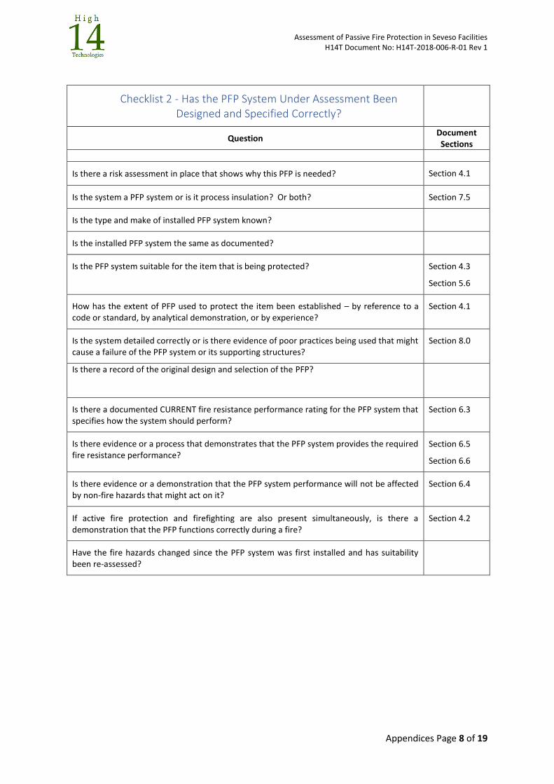
Assessment of Passive Fire Protection in Seveso Facilities H14T Document No: H14T-2018-006-R-01 Rev 1
Appendices Page 8 of 19
Checklist 2 - Has the PFP System Under Assessment Been Designed and Specified Correctly?
Question Document Sections
Is there a risk assessment in place that shows why this PFP is needed? Section 4.1
Is the system a PFP system or is it process insulation? Or both? Section 7.5
Is the type and make of installed PFP system known?
Is the installed PFP system the same as documented?
Is the PFP system suitable for the item that is being protected? Section 4.3
Section 5.6
How has the extent of PFP used to protect the item been established – by reference to a code or standard, by analytical demonstration, or by experience?
Section 4.1
Is the system detailed correctly or is there evidence of poor practices being used that might cause a failure of the PFP system or its supporting structures?
Section 8.0
Is there a record of the original design and selection of the PFP?
Is there a documented CURRENT fire resistance performance rating for the PFP system that specifies how the system should perform?
Section 6.3
Is there evidence or a process that demonstrates that the PFP system provides the required fire resistance performance?
Section 6.5
Section 6.6
Is there evidence or a demonstration that the PFP system performance will not be affected by non-fire hazards that might act on it?
Section 6.4
If active fire protection and firefighting are also present simultaneously, is there a demonstration that the PFP functions correctly during a fire?
Section 4.2
Have the fire hazards changed since the PFP system was first installed and has suitability been re-assessed?
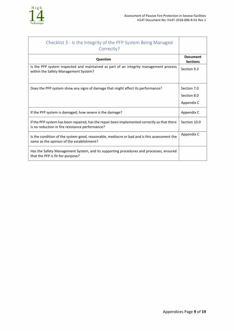
Assessment of Passive Fire Protection in Seveso Facilities H14T Document No: H14T-2018-006-R-01 Rev 1
Appendices Page 9 of 19
Checklist 3 - Is the Integrity of the PFP System Being Managed Correctly?
Question Document Sections
Is the PFP system inspected and maintained as part of an integrity management process within the Safety Management System?
Section 9.3
Does the PFP system show any signs of damage that might affect its performance? Section 7.0
Section 8.0
Appendix C
If the PFP system is damaged, how severe is the damage? Appendix C
If the PFP system has been repaired, has the repair been implemented correctly so that there is no reduction in fire resistance performance?
Section 10.0
Is the condition of the system good, reasonable, mediocre or bad and is this assessment the same as the opinion of the establishment?
Appendix C
Has the Safety Management System, and its supporting procedures and processes, ensured that the PFP is fit-for-purpose?

Assessment of Passive Fire Protection in Seveso Facilities H14T Document No: H14T-2018-006-R-01 Rev 1
Appendices Page 10 of 19
APPENDIX C: PFP DAMAGE ASSESSMENT TABLES
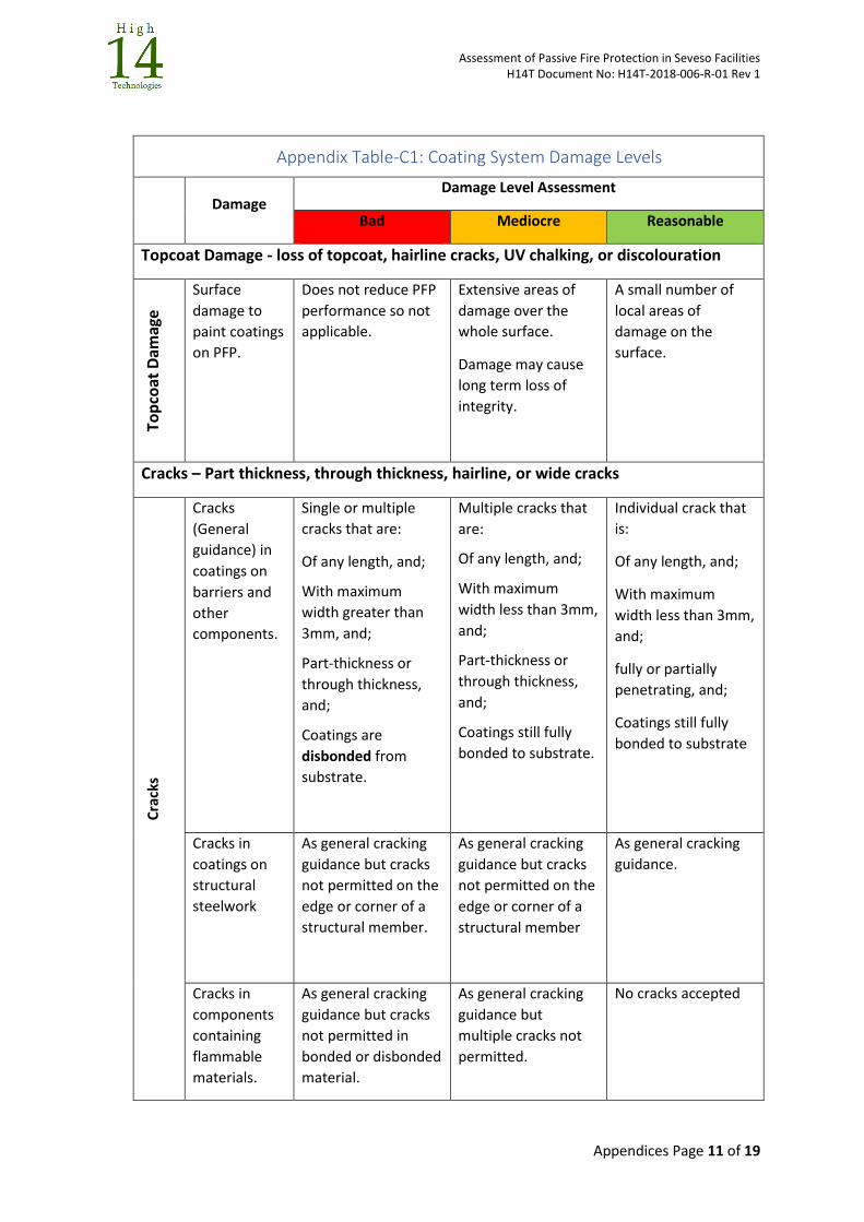
Assessment of Passive Fire Protection in Seveso Facilities H14T Document No: H14T-2018-006-R-01 Rev 1
Appendices Page 11 of 19
Appendix Table-C1: Coating System Damage Levels
Damage Damage Level Assessment
Bad Mediocre Reasonable
Topcoat Damage - loss of topcoat, hairline cracks, UV chalking, or discolouration
Top
coat
Dam
age
Surface
damage to
paint coatings
on PFP.
Does not reduce PFP
performance so not
applicable.
Extensive areas of
damage over the
whole surface.
Damage may cause
long term loss of
integrity.
A small number of
local areas of
damage on the
surface.
Cracks – Part thickness, through thickness, hairline, or wide cracks
Cra
cks
Cracks
(General
guidance) in
coatings on
barriers and
other
components.
Single or multiple
cracks that are:
Of any length, and;
With maximum
width greater than
3mm, and;
Part-thickness or
through thickness,
and;
Coatings are
disbonded from
substrate.
Multiple cracks that
are:
Of any length, and;
With maximum
width less than 3mm,
and;
Part-thickness or
through thickness,
and;
Coatings still fully
bonded to substrate.
Individual crack that
is:
Of any length, and;
With maximum
width less than 3mm,
and;
fully or partially
penetrating, and;
Coatings still fully
bonded to substrate
Cracks in
coatings on
structural
steelwork
As general cracking
guidance but cracks
not permitted on the
edge or corner of a
structural member.
As general cracking
guidance but cracks
not permitted on the
edge or corner of a
structural member
As general cracking
guidance.
Cracks in
components
containing
flammable
materials.
As general cracking
guidance but cracks
not permitted in
bonded or disbonded
material.
As general cracking
guidance but
multiple cracks not
permitted.
No cracks accepted
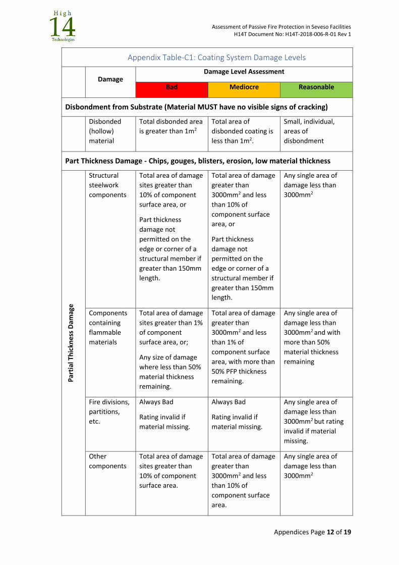
Assessment of Passive Fire Protection in Seveso Facilities H14T Document No: H14T-2018-006-R-01 Rev 1
Appendices Page 12 of 19
Appendix Table-C1: Coating System Damage Levels
Damage Damage Level Assessment
Bad Mediocre Reasonable
Disbondment from Substrate (Material MUST have no visible signs of cracking)
Disbonded
(hollow)
material
Total disbonded area
is greater than 1m2
Total area of
disbonded coating is
less than 1m2.
Small, individual,
areas of
disbondment
Part Thickness Damage - Chips, gouges, blisters, erosion, low material thickness
Par
tial
Th
ickn
ess
Dam
age
Structural
steelwork
components
Total area of damage
sites greater than
10% of component
surface area, or
Part thickness
damage not
permitted on the
edge or corner of a
structural member if
greater than 150mm
length.
Total area of damage
greater than
3000mm2 and less
than 10% of
component surface
area, or
Part thickness
damage not
permitted on the
edge or corner of a
structural member if
greater than 150mm
length.
Any single area of
damage less than
3000mm2
Components
containing
flammable
materials
Total area of damage
sites greater than 1%
of component
surface area, or;
Any size of damage
where less than 50%
material thickness
remaining.
Total area of damage
greater than
3000mm2 and less
than 1% of
component surface
area, with more than
50% PFP thickness
remaining.
Any single area of
damage less than
3000mm2 and with
more than 50%
material thickness
remaining
Fire divisions,
partitions,
etc.
Always Bad
Rating invalid if
material missing.
Always Bad
Rating invalid if
material missing.
Any single area of
damage less than
3000mm2 but rating
invalid if material
missing.
Other
components
Total area of damage
sites greater than
10% of component
surface area.
Total area of damage
greater than
3000mm2 and less
than 10% of
component surface
area.
Any single area of
damage less than
3000mm2
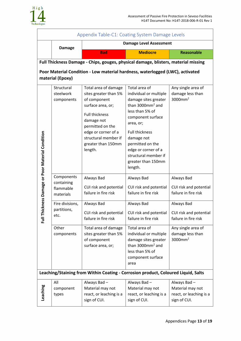
Assessment of Passive Fire Protection in Seveso Facilities H14T Document No: H14T-2018-006-R-01 Rev 1
Appendices Page 13 of 19
Appendix Table-C1: Coating System Damage Levels
Damage Damage Level Assessment
Bad Mediocre Reasonable
Full Thickness Damage - Chips, gouges, physical damage, blisters, material missing
Poor Material Condition - Low material hardness, waterlogged (LWC), activated
material (Epoxy)
Full
Thic
kne
ss D
amag
e o
r P
oo
r M
ate
rial
Co
nd
itio
n
Structural
steelwork
components
Total area of damage
sites greater than 5%
of component
surface area, or;
Full thickness
damage not
permitted on the
edge or corner of a
structural member if
greater than 150mm
length.
Total area of
individual or multiple
damage sites greater
than 3000mm2 and
less than 5% of
component surface
area, or;
Full thickness
damage not
permitted on the
edge or corner of a
structural member if
greater than 150mm
length.
Any single area of
damage less than
3000mm2
Components
containing
flammable
materials
Always Bad
CUI risk and potential
failure in fire risk
Always Bad
CUI risk and potential
failure in fire risk
Always Bad
CUI risk and potential
failure in fire risk
Fire divisions,
partitions,
etc.
Always Bad
CUI risk and potential
failure in fire risk
Always Bad
CUI risk and potential
failure in fire risk
Always Bad
CUI risk and potential
failure in fire risk
Other
components
Total area of damage
sites greater than 5%
of component
surface area, or;
Total area of
individual or multiple
damage sites greater
than 3000mm2 and
less than 5% of
component surface
area
Any single area of
damage less than
3000mm2
Leaching/Staining from Within Coating - Corrosion product, Coloured Liquid, Salts
Leac
hin
g
All
component
types
Always Bad –
Material may not
react, or leaching is a
sign of CUI.
Always Bad –
Material may not
react, or leaching is a
sign of CUI.
Always Bad –
Material may not
react, or leaching is a
sign of CUI.

Assessment of Passive Fire Protection in Seveso Facilities H14T Document No: H14T-2018-006-R-01 Rev 1
Appendices Page 14 of 19
Appendix Table-C1: Coating System Damage Levels
Damage Damage Level Assessment
Bad Mediocre Reasonable
Retention/Reinforcement/Terminations
Missing, not at mid-point, not correctly overlapped, visible, mechanical fixings
failed, damaged along edge feature, incorrectly detailed termination, missing or
damaged termination
Re
ten
tio
n/R
ein
forc
eme
nt/
Term
inat
ion
s
All
component
types
Damage with total
area greater than 5%
of component
surface area on any
individual protected
component.
Not permitted on the
edge or corner of a
structural member if
greater than 150mm
length.
Individual or multiple
damage with total
area greater than
3000mm2 and less
than 5% of
component surface
area on any
individual protected
item.
Not permitted on the
edge or corner of a
structural member if
greater than 150mm
length.
May be acceptable if
fire threat is not a jet
fire.
Any single area of
damage less than
3000mm2.
Note - May be
acceptable if fire
threat is not a jet
fire.
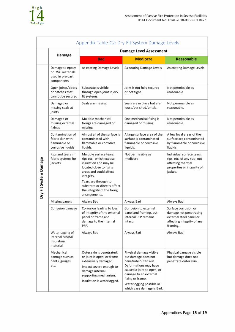
Assessment of Passive Fire Protection in Seveso Facilities H14T Document No: H14T-2018-006-R-01 Rev 1
Appendices Page 15 of 19
Appendix Table-C2: Dry-Fit System Damage Levels
Damage
Damage Level Assessment
Bad Mediocre Reasonable
Dry
Fit
Sys
tem
Dam
age
Damage to epoxy or LWC materials used in pre-cast components
As coating Damage Levels As coating Damage Levels As coating Damage Levels
Open joints/doors or hatches that cannot be secured
Substrate is visible through open joint in dry fit systems.
Joint is not fully secured or not tight.
Not permissible as reasonable
Damaged or missing seals at joints
Seals are missing. Seals are in place but are loose/perished/brittle.
Not permissible as reasonable.
Damaged or missing external fixings
Multiple mechanical fixings are damaged or missing.
One mechanical fixing is damaged or missing.
Not permissible as reasonable.
Contamination of fabric skin with flammable or corrosive liquids
Almost all of the surface is contaminated with flammable or corrosive liquids.
A large surface area of the surface is contaminated flammable or corrosive liquids.
A few local areas of the surface are contaminated by flammable or corrosive liquids.
Rips and tears in fabric systems for jackets
Multiple surface tears, rips etc. which expose insulation and may be located close to fixing areas and could affect integrity.
Tears are through to substrate or directly affect the integrity of the fixing arrangements.
Not permissible as mediocre
Individual surface tears, rips, etc. of any size, not affecting thermal properties or integrity of jacket.
Missing panels Always Bad Always Bad Always Bad
Corrosion damage Corrosion leading to loss of integrity of the external panel or frame and damage to the internal PFP.
Corrosion to external panel and framing, but internal PFP remains intact.
Surface corrosion or damage not penetrating external steel panel or affecting integrity of any framing.
Waterlogging of internal MMMF insulation material
Always Bad Always Bad Always Bad
Mechanical damage such as dents, gouges, etc.
Outer skin is penetrated, or joint is open, or frame extensively damaged.
Impact severe enough to damage internal supporting mechanism.
Insulation is waterlogged.
Physical damage visible but damage does not penetrate outer skin. Deformations may have caused a joint to open, or damage to an external fixing or frame.
Waterlogging possible in which case damage is Bad.
Physical damage visible but damage does not penetrate outer skin.
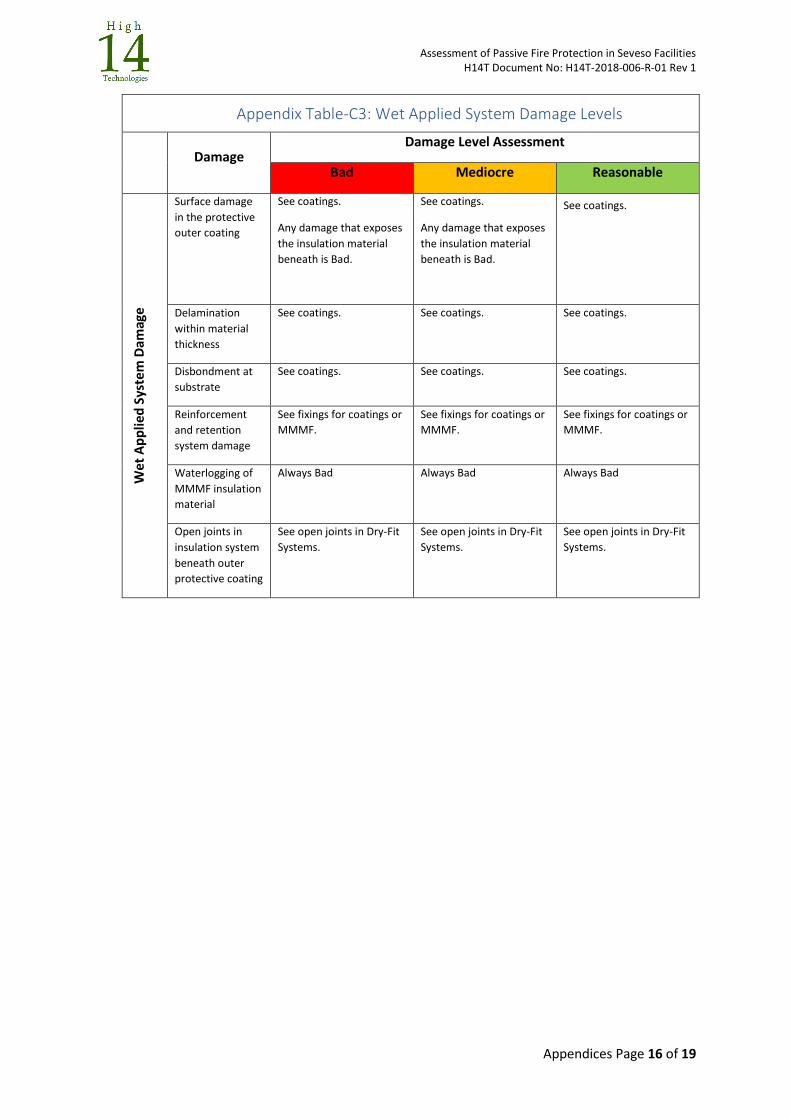
Assessment of Passive Fire Protection in Seveso Facilities H14T Document No: H14T-2018-006-R-01 Rev 1
Appendices Page 16 of 19
Appendix Table-C3: Wet Applied System Damage Levels
Damage Damage Level Assessment
Bad Mediocre Reasonable
We
t A
pp
lied
Sys
tem
Dam
age
Surface damage
in the protective
outer coating
See coatings.
Any damage that exposes
the insulation material
beneath is Bad.
See coatings.
Any damage that exposes
the insulation material
beneath is Bad.
See coatings.
Delamination
within material
thickness
See coatings. See coatings. See coatings.
Disbondment at
substrate
See coatings. See coatings. See coatings.
Reinforcement
and retention
system damage
See fixings for coatings or
MMMF. See fixings for coatings or
MMMF. See fixings for coatings or
MMMF.
Waterlogging of
MMMF insulation
material
Always Bad Always Bad Always Bad
Open joints in
insulation system
beneath outer
protective coating
See open joints in Dry-Fit
Systems.
See open joints in Dry-Fit
Systems. See open joints in Dry-Fit
Systems.
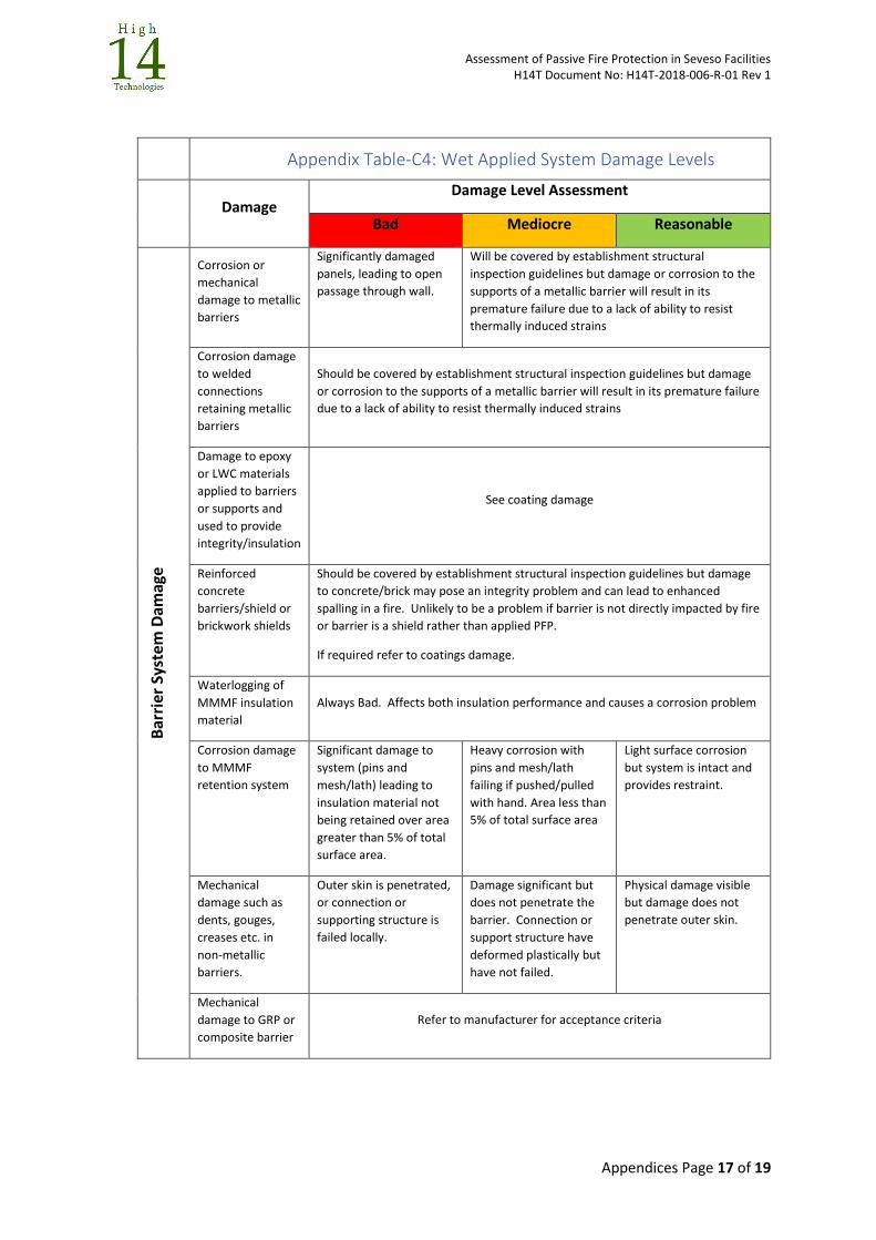
Assessment of Passive Fire Protection in Seveso Facilities H14T Document No: H14T-2018-006-R-01 Rev 1
Appendices Page 17 of 19
Appendix Table-C4: Wet Applied System Damage Levels
Damage
Damage Level Assessment
Bad Mediocre Reasonable
Bar
rier
Sys
tem
Dam
age
Corrosion or
mechanical
damage to metallic
barriers
Significantly damaged
panels, leading to open
passage through wall.
Will be covered by establishment structural
inspection guidelines but damage or corrosion to the
supports of a metallic barrier will result in its
premature failure due to a lack of ability to resist
thermally induced strains
Corrosion damage
to welded
connections
retaining metallic
barriers
Should be covered by establishment structural inspection guidelines but damage
or corrosion to the supports of a metallic barrier will result in its premature failure
due to a lack of ability to resist thermally induced strains
Damage to epoxy
or LWC materials
applied to barriers
or supports and
used to provide
integrity/insulation
See coating damage
Reinforced
concrete
barriers/shield or
brickwork shields
Should be covered by establishment structural inspection guidelines but damage
to concrete/brick may pose an integrity problem and can lead to enhanced
spalling in a fire. Unlikely to be a problem if barrier is not directly impacted by fire
or barrier is a shield rather than applied PFP.
If required refer to coatings damage.
Waterlogging of
MMMF insulation
material
Always Bad. Affects both insulation performance and causes a corrosion problem
Corrosion damage
to MMMF
retention system
Significant damage to
system (pins and
mesh/lath) leading to
insulation material not
being retained over area
greater than 5% of total
surface area.
Heavy corrosion with
pins and mesh/lath
failing if pushed/pulled
with hand. Area less than
5% of total surface area
Light surface corrosion
but system is intact and
provides restraint.
Mechanical
damage such as
dents, gouges,
creases etc. in
non-metallic
barriers.
Outer skin is penetrated,
or connection or
supporting structure is
failed locally.
Damage significant but
does not penetrate the
barrier. Connection or
support structure have
deformed plastically but
have not failed.
Physical damage visible
but damage does not
penetrate outer skin.
Mechanical
damage to GRP or
composite barrier
Refer to manufacturer for acceptance criteria

Assessment of Passive Fire Protection in Seveso Facilities H14T Document No: H14T-2018-006-R-01 Rev 1
Appendices Page 18 of 19
Appendix Table-C5: Penetration System Damage Levels
Damage Damage Level Assessment
Bad Mediocre Reasonable
Pen
etra
tio
n S
eal D
amag
e
8
Certified Pipe
Penetrations
Gaiter Type
Rating does not match
barrier.
Seal is missing, installed
incorrectly.
Seal fabric is torn,
stretched, disconnected or
has major contamination.
Retention straps are
missing, damaged or non-
standard.
Insulation material within
seal us waterlogged.
Collar through barrier has
major corrosion.
Not Applicable
Note –If there is the
potential for a seal to fail
then it will allow smoke and
gas into a safe area. Most
significant forms of damage
to a seal are usually enough
to fail the seal and
therefore partial damage is
not acceptable.
Surface corrosion of fixings
and collar
Damaged but not through
thickness of the fabric
Certified Pipe
Penetrations
Mastic Sealing
Type
Rating does not match
barrier.
Seal is missing, or not
installed as certified.
Mastic is split,
disconnected,
contaminated or not
applied correctly.
Collar through barrier has
major corrosion.
Not Applicable Surface corrosion of fixings
and collar
Certified Pipe
Penetration
Pipe Collar-Type
Rating does not match
barrier.
Seal is missing, or not
installed as certified.
Components, including
bolts, missing or loose.
Collar through barrier has
major corrosion.
Not Applicable Surface corrosion of fixings
and collar
Cable
Penetrations
Transit blocks
Rating does not match
barrier
Incorrectly fitted or missing
blocks.
Collar through barrier has
major corrosion.
Not Applicable Surface corrosion of fixings
and collar

Assessment of Passive Fire Protection in Seveso Facilities H14T Document No: H14T-2018-006-R-01 Rev 1
Appendices Page 19 of 19
Appendix Table-C5: Penetration System Damage Levels
Damage Damage Level Assessment
Bad Mediocre Reasonable
Non-standard
Pipe Penetrations
Bespoke
arrangement
Rating does not match
barrier.
Seal is missing.
Not certified and no
evidence of design
calculations exists.
Inadequate design of
coatback or insulation
arrangements to prevent
heat transfer.
Damage to coating material
used for insulation (see
coating damage assessment
table.
Insulation material within
seal us waterlogged.
Collar through barrier has
major corrosion.
Not Applicable Surface corrosion of fixings
and collar
Doors
Rating does not match
barrier.
Installed incorrectly.
Damaged hinges, latches,
or seals
Major corrosion damage to
door skin or frame
Not Applicable Surface corrosion of door
or frame.
Windows
Rating does not match
barrier.
Glass cracked or broken, or
seals damaged
Major corrosion damage to
window frames.
Not Applicable
Surface corrosion of
window frame.
Ducts Treat as a bespoke
penetration Not Applicable
Treat as a bespoke
penetration