Embed Size (px)
Citation preview

ORNL/TM-2006/114
Assessment of Nuclear-Hydrogen Synergies with Renewable Energy
Systems and Coal Liquefaction Processes
C. W. Forsberg
Oak Ridge National Laboratory
August 2006

This report was prepared as an account of work sponsored by an agency of the United States Government. Neither the United States government nor any agency thereof, nor any of their employees, makes any warranty, express or implied, or assumes any legal liability or responsibility for the accuracy, completeness, or usefulness of any information, apparatus, product, or process disclosed, or represents that its use would not infringe privately owned rights. Reference herein to any specific commercial product, process, or service by trade name, trademark, manufacturer, or otherwise, does not necessarily constitute or imply its endorsement, recommendation, or favoring by the United States Government or any agency thereof. The views and opinions of authors expressed herein do not necessarily state or reflect those of the United States Government or any agency thereof.
ORNL/TM-2006/114
Assessment of Nuclear-Hydrogen Synergies with Renewable Energy Systems and Coal Liquefaction Processes
C. W. Forsberg* Oak Ridge National Laboratory*
Oak Ridge, Tennessee
Date Published: August 2006
Prepared by OAK RIDGE NATIONAL LABORATORY
Oak Ridge, Tennessee 37831-6285 managed by
UT-BATTELLE, LLC for the
U.S. DEPARTMENT OF ENERGY under contract DE-AC05-00OR22725
_________________________ *P.O. Box 2008, Oak Ridge, TN 37831-6165; Tel: (865) 574-6783; Email: [email protected]

Blank page

iii
CONTENTS
Page LIST OF FIGURES ...................................................................................................................................... v LIST OF TABLES........................................................................................................................................ v EXECUTIVE SUMMARY.........................................................................................................................vii ABSTRACT...............................................................................................................................................xiii 1. INTRODUCTION.................................................................................................................................. 1
2. CHARACTERISTICS OF NUCLEAR HYDROGEN .......................................................................... 3 2.1 HYDROGEN PRODUCTION ..................................................................................................... 3 2.2 HYDROGEN STORAGE ............................................................................................................ 4 2.3 OXYGEN STORAGE.................................................................................................................. 8 3. RENEWABLE NUCLEAR-HYDROGEN SYNERGIES ................................................................... 11 3.1 SYSTEMS ANALYSIS.............................................................................................................. 11 3.2 HYDROGEN INTERMEDIATE AND PEAK ELECTRICAL SYSTEM ................................ 11 3.2.1 The Renewable Electricity Production Challenge......................................................... 11 3.2.2 Hydrogen Intermediate and Peak Electrical System...................................................... 13 3.2.3 Peak Electricity Production ........................................................................................... 13 3.2.3.1 HIPES Production of Electricity with a Steam Turbine................................ 14 3.2.3.2 HIPES Production of Electricity with Fuel Cells .......................................... 17 3.2.4 Hydrogen and Oxygen Production ................................................................................ 21 3.2.5 Implications and Implementation of HIPES.................................................................. 21 3.3 LIQUID FUELS AND BIOMASS............................................................................................. 22
4. FOSSIL-LIQUIFACTION NUCLEAR-HYDROGEN SYNERGIES................................................. 25
4.1 LIQUID-FUEL SYSTEM CONSIDERATIONS....................................................................... 25
4.2 LIQUIFACTION PROCESSES ................................................................................................. 27 4.2.1 Process Options ............................................................................................................. 27 4.2.2 Fischer-Tropsch Processing........................................................................................... 28 4.2.2.1 Chemistry ...................................................................................................... 28 4.2.2.2 Flowsheet ...................................................................................................... 30 4.2.3 Research and Development Needs ................................................................................ 31

iv
CONTENTS (continued)
4.3 OTHER LIQUEFACTION PROCESSES.................................................................................. 31 4.4 FUTURE FUEL TRANSITIONS............................................................................................... 31
5. OTHER SYNERGIES.......................................................................................................................... 33 6. CONCLUSIONS AND RECOMMENDATIONS............................................................................... 35 7. REFERENCES..................................................................................................................................... 37
v
LIST OF FIGURES
Figure Page ES.1 Hydrogen Intermediate and Peak Electrical System........................................................................ x ES.2a HIPES High-Temperature Steam Turbine System ......................................................................... xi ES.2b Fuel-Oxygen Combustor................................................................................................................. xi ES.3 Equivalent carbon dioxide releases per SUV vehicle mile for diesel fuel produced from different feedstocks........................................................................................................................xii 2.1 Technologies for underground storage of compressed gases........................................................... 5 2.2 Surface facility of the ConocoPhillips hydrogen storage cavern..................................................... 7 3.1 Price of electricity [$/MW(e)-h] as a function of time in Alberta, Canada ................................... 12 3.2 Hydrogen Intermediate and Peak Electricity System with hydrogen from a nuclear power plant ..................................................................................................................... 14 3.3 HIPES high-temperature steam turbine system ............................................................................. 15 3.4 Natural gas-oxygen combustor ...................................................................................................... 16 3.5 Alkaline fuel cell............................................................................................................................ 18 3.6 Cenergie alkaline-fuel-cell stack.................................................................................................... 19 3.7 Schematic of interior of Cenergie alkaline-fuel-cell stack............................................................. 20 4.1 Rate of discovery and consumption of crude oils vs time ............................................................. 25 4.2 Equivalent carbon dioxide releases per SUV vehicle mile for diesel fuel produced from different feedstocks........................................................................................................................ 26 4.3 Nuclear coal liquefaction and coal liquefaction by the indirect coal-gasification Fischer-Tropsch process ................................................................................................................ 29
LIST OF TABLES
Table Page 2.1 U.S. underground natural gas storage capacity in 2001...................................................................... 6

vi
Blank page

vii
EXECUTIVE SUMMARY The production of hydrogen using nuclear energy (nuclear hydrogen) has several characteristics: the raw material is water, hydrogen, and oxygen are produced, the scale of operations is very large, and low-cost heat is available from the nuclear reactors. The high-volume centralized production of hydrogen and oxygen couples with low-cost centralized storage of hydrogen and oxygen in underground facilities. This unique combination of characteristics makes possible synergies between nuclear hydrogen production and the production of (1) electricity and liquid fuels using renewable energy sources and (2) liquid fuels from fossil fuels such as coal. These synergisms have the potential to have lower costs and smaller environmental impacts than comparable nuclear-only, renewable-only, or fossil-only systems. These systems may become early markets for nuclear hydrogen because of the added benefits that nuclear hydrogen brings to these applications relative to the production of hydrogen as a fuel. Three systems were examined. Renewable Nuclear-Hydrogen Electric Systems A major limitation of renewable electrical systems (wind, solar, etc.) is that electricity production does not match demand. If the renewable component of the electric grid exceeds 10 to 15%, backup power is required to provide electricity when the wind speed slows or when cloudy conditions exist. The cost of this backup power creates a very large economic barrier to the large-scale use of renewable electricity production. The solution to this economic limitation is the development of electric generating systems with very low capital costs to produce low-cost intermediate and peak power when required; that is, when the wind does not blow or the sun does not shine. Nuclear-hydrogen systems that coproduce hydrogen and oxygen, combined with low-cost storage of these gases, may provide a method to produce low-cost peak electricity on demand to complement the renewable output characteristics. Because such power-generating equipment may operate less than 10% of the time, peak electricity production with current technology can be 10 times or more per kilowatt hour than base-load electricity production. The Hydrogen Intermediate and Peak Electrical System (HIPES, see Fig. ES.1), which consists of three major components, may enable the development of hydrogen-to-electricity systems with very low capital costs. • Hydrogen production. Nuclear hydrogen is produced from water, with the by-product production of
oxygen. This equipment is operated thousands of hours per year. Production methods may include near-term options, such as conventional electrolysis at night, to longer-term options, such as steady-state thermochemical hydrogen production processes. Hydrogen and oxygen are produced in all nuclear hydrogen systems.
• Hydrogen and oxygen storage. Large underground storage facilities are used for the low-cost safe
storage of hydrogen and oxygen—the same technology used for low-cost storage of natural gas. Hydrogen and oxygen can be stored daily, weekly, or seasonally until needed in very large quantities.
• Hydrogen-to-electricity conversion. High-efficiency fuel-to-electricity systems with very low capital
costs are required and are potentially possible because of the use of pure oxygen and hydrogen. Two such systems have been identified. Hydrogen and oxygen can be burnt to produce very high temperature, high-pressure steam for a high-efficiency (70%) steam turbine, without a boiler and the resulting costs and efficiency limitations it creates (Fig. ES.2). Alternatively, lower-cost fuel cells are possible because oxygen replaces air and drastically reduces the cost of the fuel cell while increasing the efficiency. The cavern storage of hydrogen and oxygen is at high pressure. The higher pressure hydrogen and oxygen lowers the costs of both the steam turbine and fuel-cell power-conversion options.

viii
06-015
Fuel Cells, Steam Turbines, or
Other TechnologyH2 ProductionNuclear Reactor
2H2O
Heatand/or
Electricity
2H2 + O2Underground
Hydrogen/Oxygen (Optional)Storage
Relative Capital Cost/KW
Facility
$$$$ $$ $ $$
EnergyProduction Rate vs Time
Time Time Time
Constant Constant Variable
Fuel Cells, Steam Turbines, or
Other TechnologyH2 ProductionNuclear Reactor
2H2O
Heatand/or
Electricity
2H2 + O2Underground
Hydrogen/Oxygen (Optional)Storage
Relative Capital Cost/KW
Facility
$$$$ $$ $ $$
EnergyProduction Rate vs Time
Time Time Time
Constant Constant Variable
Fig. ES.1. Hydrogen Intermediate and Peak Electrical System. If HIPES can be developed, it represents an initial market for nuclear hydrogen that has two major advantages: (1) the customers are the same utilities that operate nuclear power plants and operate wind and other renewable electricity production facilities and (2) there are no major hydrogen infrastructure requirements. HIPES is based on two unique characteristics of nuclear hydrogen: coproduction of hydrogen and oxygen and centralized production that matches the characteristics of low-cost underground centralized storage of hydrogen and oxygen. Most of the technologies required for HIPES are being developed for other purposes. For further development, systems and economic studies are required, as well as improvements in bulk hydrogen and oxygen storage technologies. Biomass-Liquid-Fuels Nuclear-Hydrogen Systems A rapidly growing interest is emerging in liquid transport fuels produced from biomass. However, it is estimated that even with full deployment, the limited availability of biomass could produce no more than 30% of the world’s liquid-fuel needs.

ix
Steam
1500º C
Hydrogen
Water
PumpCondenser
Burner
SteamTurbine
InOut
CoolingWater
GeneratorSteam
1500º C
Hydrogen
Water
PumpCondenser
Burner
SteamTurbine
InOut
CoolingWater
Generator
Oxygen
Fig. ES.2a. HIPES High-Temperature Steam Turbine System.
Fig. ES.2b. Fuel-Oxygen Combustor (Courtesy of Clean Energy Systems).

x
Illinois #6 Coal Baseline
Pipeline Natural Gas
Wyoming Sweet Crude Oil
Venezuelan Syncrude
0
200
400
600
800
1000
1200
Gre
enho
use
Impa
cts
(g C
O2-
eq/m
ile in
SU
V)
Conversion/RefiningTransportation/Distribution
End Use CombustionExtraction/Production
Business As Usual
Using Fuel
Making and
Delivering of Fuel
(Fisher-TropschLiquids)
(Fisher-TropschLiquids)
Source of G
reenhouse Impacts
In the conversion of biomass into liquid fuels, only a fraction of the carbon is converted to fuel. If outside hydrogen were available, all of the carbon could be converted to high-quality hydrocarbon liquid fuels. This situation could potentially double or triple the energy content of liquid fuels per unit of biomass. Facilities for conversion of biomass to liquid fuels are medium-sized plants in rural areas—characteristics that minimize the costs of a hydrogen distribution system. Nuclear hydrogen combined with central storage can provide the hydrogen on the yearly schedule to support such facilities. Current technologies can convert biomass and external hydrogen to liquid fuels; however, methods for the direct conversion of biomass to liquid fuels with the addition of hydrogen may be required to significantly improve economics. Fossil-Liquefaction Nuclear-Hydrogen Systems The era of producing liquid fuels from crude oil is ending. The rate of discoveries of crude oil is far lower than the rate of consumption. Although liquid fuels can be and are commercially made from coal in several parts of the world, this method of liquid-fuel production implies a massive increase in carbon dioxide emissions per vehicle mile traveled relative to that for liquid fuels made from crude oil (Fig. ES.3). In conversion of coal and other low-cost abundant fossil fuels to liquid fuels, half the coal is used to make hydrogen, produce oxygen (a required input to coal liquefaction), and provide heat to the fuel processing plants. Research is under way to sequester carbon dioxide from power plants and industrial facilities and thus minimize the environmental impacts from using coal. However, sequestration of carbon dioxide requires very special geological conditions that may or may not be located where the fossil fuels and coal liquefaction plants would be built. Producing liquid fuels from coal and other low-grade fossil sources without large carbon dioxide emissions from the production process is challenging.
Fig. ES.3. Equivalent carbon dioxide releases per SUV vehicle mile for diesel fuel produced from different feedstocks.

xi
Nuclear hydrogen has the unique characteristics that it is a highly centralized method to produce hydrogen and oxygen in very large quantities. The major inputs to produce liquid fuels from coal and other abundant fossil fuels without producing large quantities of carbon dioxide in the production process are (1) large quantities of hydrogen and (2) large quantities of oxygen. The outputs and scale of a nuclear-hydrogen production complex match the required inputs to a coal liquefaction plant. Potentially of equal importance, the nuclear-hydrogen plant can be collocated with the coal liquefaction plant. Coal liquefaction technologies are well understood. However, the use of outside production of hydrogen and oxygen will alter the internal flowsheets of a coal liquefaction plant. Engineering studies are required to optimize these flowsheets for a nuclear-hydrogen coal liquefaction plant and to assess the economics. Conclusions The long-term goal of the U.S. Department of Energy (DOE) Nuclear Hydrogen Initiative is the production of hydrogen as a non-polluting fuel for cars and trucks that also eliminates our dependence on foreign crude oil. One of the major challenges is the transition to a hydrogen economy that involves developing the technology, scaling it up to industrial scale, and then deploying the technology. Nuclear hydrogen has a unique set of characteristics that distinguishes it from other hydrogen production methods. These characteristics enable potential synergistic systems that use the complementary characteristics of nuclear hydrogen with renewable and fossil energy systems. These combined systems represent alternative uses of nuclear hydrogen and can be developed and deployed independently of the use of nuclear hydrogen for transport fuels. As such, they are potential first markets for large nuclear hydrogen production complexes that do not require the construction of a massive hydrogen infrastructure (pipelines, distribution lines) or development of a large consumer market to use the hydrogen. These options avoid the “chicken and egg” problem in deployment of large-scale systems. In addition to the direct benefits that they provide, such options can also afford a bridge to a hydrogen economy by creating the initial hydrogen production infrastructure. Each of these options is technically feasible. However, additional development and conceptual design activities will be required in each case before the economics of each of these options is fully understood and deployment can be considered. The further development of these potentially near-term bridges to a larger hydrogen economy requires an integrated and collaborative research effort within multiple offices of DOE, laboratories, and industry. Initial steps would include a collaborative systems analysis between groups involving solar, nuclear, and fossil systems to compare projected costs for integrated versus single-energy-source systems.

xii
Blank page

xiii
ABSTRACT The production of hydrogen using nuclear energy (nuclear hydrogen) has several characteristics: the raw material is water, hydrogen, and oxygen are produced, the scale of operations is very large, and low-cost heat is available from the nuclear reactors. The high-volume centralized production couples with low-cost centralized storage of hydrogen and oxygen in underground facilities. This unique combination of characteristics makes possible synergies between nuclear hydrogen and (1) renewable energy systems producing electricity or liquid fuels and (2) coal liquefaction systems. Systems that combine nuclear hydrogen with renewable and fossil energy systems have potentially lower costs and smaller environmental impacts than comparable nuclear-only, renewable-only, or fossil-only systems. Two examples of such synergisms are based on the centralized coproduction of hydrogen and oxygen—a unique defining characteristic of nuclear hydrogen versus hydrogen produced using fossil fuels or renewable energy sources. A major barrier to the large-scale use of renewable electricity is the high capital cost of backup electricity when wind or solar sources are not available. Low-capital-cost systems for the production of backup or peak electricity have been identified in which the low capital cost is made possible by using oxygen rather than air to consume the hydrogen as a fuel in peak electricity production systems. A second example is the conversion of coal and other carbon sources into liquid transport fuels where the two primary inputs are hydrogen and oxygen—the products of a nuclear-hydrogen facility. These synergistic systems may become early markets for nuclear hydrogen because of the added benefits that nuclear hydrogen brings to these applications relative to the production of hydrogen as a transport fuel. Because of the potential simultaneous benefits to nuclear-hydrogen, renewables, and coal liquefaction development and commercialization, these options have the potential for a high return on investment in terms of research and development.

xiv
Blank page

1
1. INTRODUCTION Different energy technologies have different strengths and weaknesses. Because of these differences, the optimum energy system depends upon the application and the location. Nuclear energy is intrinsically a large-scale centralized method of energy production. Production of hydrogen from nuclear energy (nuclear hydrogen) is thus also an intrinsically large-scale centralized method for hydrogen production. The different characteristics of various energy systems imply that combining several energy technologies in a system often results in superior economics and reduced environmental impacts relative to using a single energy technology. An example is the electrical grid in the United States, which simultaneously uses nuclear, fossil, wind, and other technologies in one system to maximize performance. The objective of this report is to identify, describe, and analyze potential synergisms between nuclear hydrogen and (1) renewable energy systems and (2) coal liquefaction systems. This information can then be used to help charter a path forward for nuclear hydrogen, including the development of cooperative mutually beneficial programs with renewable and fossil energy programs. Synergistic systems are those in which the use of two technologies together lowers the overall costs, reduces the technical barriers, or decreases the environmental impacts relative to the use of either system by itself. The identification of synergisms between nuclear hydrogen and other energy systems is important in that it helps to define research and development goals, requirements, and first markets for implementation of nuclear hydrogen systems. Section 2 of this report describes the characteristics of nuclear-hydrogen production and the associated technologies. Section 3 describes and analyzes potential synergisms between nuclear hydrogen and renewable energy sources, while Sect. 4 describes and analyzes potential synergisms between nuclear hydrogen and the production of liquid fuels. Section 5 discusses other potential synergisms that were identified but not analyzed. The last section (Sect. 6) summarizes conclusions and makes recommendations.

2
Blank page

3
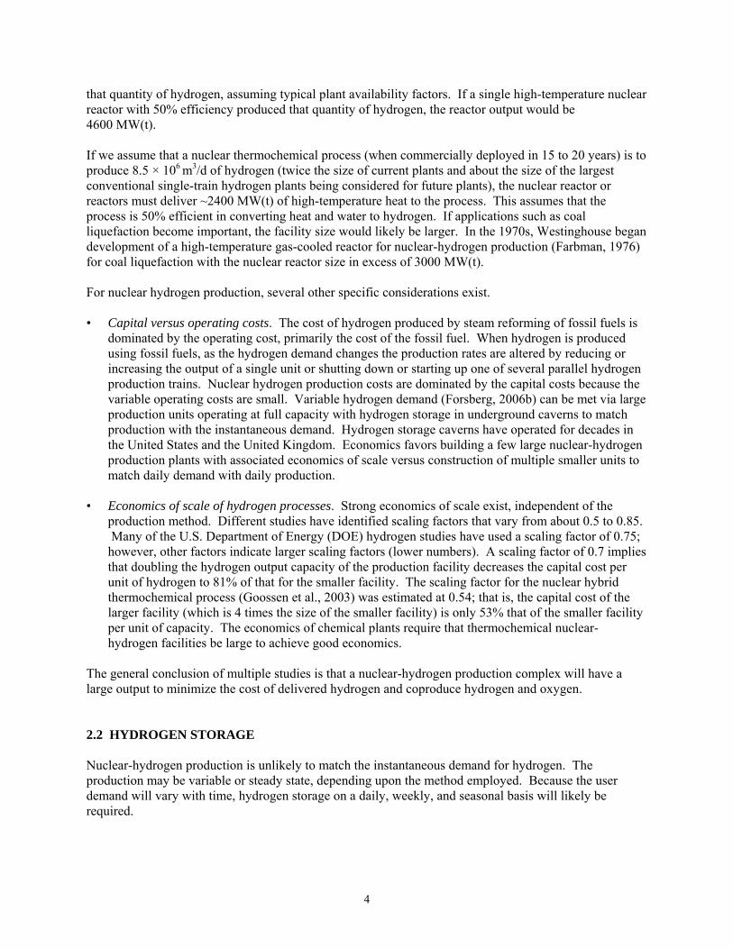
2. CHARACTERISTICS OF NUCLEAR HYDROGEN Nuclear hydrogen has several characteristics: the raw feed material is water, hydrogen, and oxygen are produced; the scale of operations is very large; and low-cost heat is available from the nuclear reactors. The high-volume production couples with low-cost centralized storage of hydrogen and oxygen in underground facilities. This unique combination of characteristics defines nuclear hydrogen and defines its potential role in the global energy system relative to other hydrogen production methods. 2.1 HYDROGEN PRODUCTION The energy from nuclear reactors can convert water to hydrogen and oxygen. The existing technology is electrolysis, the room-temperature process that converts electricity and water to hydrogen and oxygen. Three other classes of technologies, which use less electricity and more heat to convert water to hydrogen and oxygen, are being developed (Nuclear Energy Agency, 2003). Because heat is less expensive than electricity, these technologies have the long-term potential to produce hydrogen at lower costs. The energy inputs to high-temperature electrolysis are electricity and heat to convert water to steam. For hybrid cycles, the energy inputs are electricity and high-temperature heat to drive chemical reactions, while thermochemical cycles require only high-temperature heat to drive a series of chemical reactions. Various studies (Shiozawa et al., 2000; Farbman, 1976) project the cost of hydrogen production via the thermochemical processes to be as low as 60% of those for electrolysis, with the long-term potential of heat-to-hydrogen efficiencies in excess of 60% (which represents the potential for major improvements over time). Hydrogen demand is growing rapidly today because of the need to upgrade heavy crude oil to liquid fuels (gasoline, diesel, and jet fuel) and to improve the quality of liquid fuels by removal of sulfur compounds. Almost all hydrogen today is made by steam reforming of fossil fuels. In the United States, natural gas is the preferred fuel for hydrogen production. The size of the hydrogen production unit is controlled by the market need, with multiple hydrogen production units typically located at a single facility (Ondrey, 2006) to ensure a continuous supply of hydrogen. Ten years ago, a typical single-train hydrogen plant produced 1.4 × 10⁶ m3/d (50 × 106 ft3/d). Today, there are almost three dozen units with production capacities exceeding 2.8 × 10⁶ m3/d, with new units coming online with capacities of 3.7 × 10⁶ m3/d and plans for single-train units twice that size. The growth in plant size is driven by the economics of scale and the existence of markets sufficiently large to consume the hydrogen produced by these facilities. Miller and Duffy (2003) have estimated the scaling factor for hydrogen plants operating on natural gas to be 0.66. This implies that if the plant size is increased by 4, the capital cost increases by a factor of only 2.5; that is, the capital cost of the larger facility is only 62% of that for the smaller facility per unit of capacity. For larger-scale hydrogen applications—such as coal liquefaction (Forsberg, 2005b)—the economic optimum hydrogen plant size would be larger. To provide perspective on the current scale of industrial hydrogen operations, the largest hydrogen production complex now under construction (Haldor Topsoe A/S, 2005) to support oil refinery operations will have four parallel trains producing hydrogen from natural gas. Each train will produce 3.9 × 10⁶ m3/d of hydrogen, with a total facility output is 15.6 × 10⁶ m3/d. The power equivalent of that rate of hydrogen production is about 2300 MW. Thus, if electrolysis were used with typical efficiencies, approximately three 1000-MW(e) nuclear plants would be required to provide the electricity to produce
4
that quantity of hydrogen, assuming typical plant availability factors. If a single high-temperature nuclear reactor with 50% efficiency produced that quantity of hydrogen, the reactor output would be 4600 MW(t). If we assume that a nuclear thermochemical process (when commercially deployed in 15 to 20 years) is to produce 8.5 × 10⁶ m3/d of hydrogen (twice the size of current plants and about the size of the largest conventional single-train hydrogen plants being considered for future plants), the nuclear reactor or reactors must deliver ~2400 MW(t) of high-temperature heat to the process. This assumes that the process is 50% efficient in converting heat and water to hydrogen. If applications such as coal liquefaction become important, the facility size would likely be larger. In the 1970s, Westinghouse began development of a high-temperature gas-cooled reactor for nuclear-hydrogen production (Farbman, 1976) for coal liquefaction with the nuclear reactor size in excess of 3000 MW(t). For nuclear hydrogen production, several other specific considerations exist. • Capital versus operating costs. The cost of hydrogen produced by steam reforming of fossil fuels is
dominated by the operating cost, primarily the cost of the fossil fuel. When hydrogen is produced using fossil fuels, as the hydrogen demand changes the production rates are altered by reducing or increasing the output of a single unit or shutting down or starting up one of several parallel hydrogen production trains. Nuclear hydrogen production costs are dominated by the capital costs because the variable operating costs are small. Variable hydrogen demand (Forsberg, 2006b) can be met via large production units operating at full capacity with hydrogen storage in underground caverns to match production with the instantaneous demand. Hydrogen storage caverns have operated for decades in the United States and the United Kingdom. Economics favors building a few large nuclear-hydrogen production plants with associated economics of scale versus construction of multiple smaller units to match daily demand with daily production.
• Economics of scale of hydrogen processes. Strong economics of scale exist, independent of the
production method. Different studies have identified scaling factors that vary from about 0.5 to 0.85. Many of the U.S. Department of Energy (DOE) hydrogen studies have used a scaling factor of 0.75; however, other factors indicate larger scaling factors (lower numbers). A scaling factor of 0.7 implies that doubling the hydrogen output capacity of the production facility decreases the capital cost per unit of hydrogen to 81% of that for the smaller facility. The scaling factor for the nuclear hybrid thermochemical process (Goossen et al., 2003) was estimated at 0.54; that is, the capital cost of the larger facility (which is 4 times the size of the smaller facility) is only 53% that of the smaller facility per unit of capacity. The economics of chemical plants require that thermochemical nuclear-hydrogen facilities be large to achieve good economics.
The general conclusion of multiple studies is that a nuclear-hydrogen production complex will have a large output to minimize the cost of delivered hydrogen and coproduce hydrogen and oxygen. 2.2 HYDROGEN STORAGE Nuclear-hydrogen production is unlikely to match the instantaneous demand for hydrogen. The production may be variable or steady state, depending upon the method employed. Because the user demand will vary with time, hydrogen storage on a daily, weekly, and seasonal basis will likely be required.
5
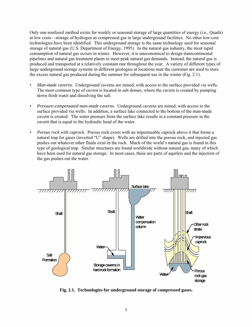
Only one nonfossil method exists for weekly or seasonal storage of large quantities of energy (i.e., Quads) at low costs—storage of hydrogen as compressed gas in large underground facilities. No other low-cost technologies have been identified. This underground storage is the same technology used for seasonal storage of natural gas (U.S. Department of Energy, 1995). In the natural gas industry, the most rapid consumption of natural gas occurs in winter. However, it is uneconomical to design transcontinental pipelines and natural gas treatment plants to meet peak natural gas demands. Instead, the natural gas is produced and transported at a relatively constant rate throughout the year. A variety of different types of large underground storage systems in different geologies at locations near the customer are used to store the excess natural gas produced during the summer for subsequent use in the winter (Fig. 2.1). • Man-made caverns. Underground caverns are mined, with access to the surface provided via wells.
The most common type of cavern is located in salt domes, where the cavern is created by pumping down fresh water and dissolving the salt.
• Pressure-compensated man-made caverns. Underground caverns are mined, with access to the
surface provided via wells. In addition, a surface lake connected to the bottom of the man-made cavern is created. The water pressure from the surface lake results in a constant pressure in the cavern that is equal to the hydraulic head of the water.
• Porous rock with caprock. Porous rock exists with an impermeable caprock above it that forms a
natural trap for gases (inverted “U” shape). Wells are drilled into the porous rock, and injected gas pushes out whatever other fluids exist in the rock. Much of the world’s natural gas is found in this type of geological trap. Similar structures are found worldwide without natural gas, many of which have been used for natural gas storage. In most cases, these are parts of aquifers and the injection of the gas pushes out the water.
Fig. 2.1. Technologies for underground storage of compressed gases.
Salt Formation
Shaft
Salt Formation
Shaft Shaft
Water
Storage caverns in hard-rock formation
Water compensation column
Surface lake
Shaft
Water
Storage caverns in hard-rock formation
Water compensation column
Surface lake
Shaft
Other rock strata
Impervious caprock
Porous rock gas storage
Water
Shaft
Other rock strata
Impervious caprock
Porous rock gas storage
Water

6
The total existing natural gas storage capacity in the United States is 8.4 × 1012 ft3, which is equivalent to about one-third of the natural gas consumed in the United States in 1 year. Table 2.1 identifies the existing underground natural gas storage facilities by type and capacity. These facilities are large, with average storage capacities between 10 and 20 billion cubic feet. The usable capacity depends upon the required pressure at which the natural gas must be delivered to the pipeline and the rate of delivery. For high-pressure gas delivery, the capacity is about one-half, with the remaining half used as buffer gas to maintain storage facility pressure and minimize compression back to pipeline pressures.
Table 2.1. U.S. underground natural gas storage capacity in 2001
Type of Storage Capacity Number of Facilities Capacity (109 ft3)
Salt caverns 28 218
Aquifers 39 1195
Depleted fields 351 7002
Total 418 8357 For several decades, industrial facilities in the United States and the United Kingdom have used salt caverns to store hydrogen, thus meeting variable industrial hydrogen demand while allowing shutdowns of hydrogen production plants for maintenance. Hydrogen storage should be viable in other geologies, but this application of the technology has not been demonstrated in other geologies. An example of a hydrogen storage facility is the ConocoPhillips Clemens Terminal in Texas. The hydrogen is stored in a solution-mined salt cavern with the cavern roof ~2800 ft underground. The actual cavern is a cylinder with a diameter of ~160 ft, a height of ~1000 ft, and a usable hydrogen capacity of 1066 million standard cubic feet (MMSCF), or 2520 metric tons. Figure 2.2 shows the surface equipment facility associated with this storage cavern. The capital cost of an underground facility to store 1- GW-year of hydrogen (lower heating value) is estimated to be about $200–$400 million ($0.80–1.60/kg of storage capacity). The value of the hydrogen stored in such a facility will exceed the capital cost of the facility. The capital cost is sufficiently low as to make viable the seasonal storage of hydrogen. The capital cost estimate (1) assumes that the cost per unit volume stored is the same for hydrogen and natural gas and (2) is based on reported capital costs for planned natural gas storage facilities (Thompson, 1997). Various studies indicate that hydrogen storage costs per unit volume (Foh et al., 1979) are similar to those of natural gas. Costs for underground hydrogen storage are about 2 orders of magnitude lower than those for other forms of hydrogen storage (high-pressure cylinders, etc.). If the use of fossil fuels is constrained, underground storage is the only existing viable method to store the quantities of energy needed for multiweek or seasonal changes in energy demand. The characteristics of the bulk storage system will drive the characteristics of much of the hydrogen economy, including the likely roles of nuclear hydrogen relative to other methods of hydrogen production.

7
Fig. 2.2. Surface facility of the ConocoPhillips hydrogen storage cavern. Reprinted with the permission from ConocoPhillips
Hydrogen transport requires the movement of mass rather than electrons. In an electrical grid, electricity can be converted from low voltage (use or generation) to high voltage (transport), or vise versa, by the same electrical transformer at high efficiencies. Thus, electrical systems accommodate energy flow in either direction. In contrast, different equipment is required to convert low-pressure hydrogen to high-pressure hydrogen, or vise versa. Furthermore, the efficiency of converting low-pressure hydrogen to high-pressure hydrogen is strongly dependent on the scale of equipment, with small gas compressors having low efficiencies. As is the case for natural gas, hydrogen distribution systems are directional and favor flow from centralized high-pressure sources to distributed low-pressure users.

8
The combination of the transportation characteristics of hydrogen and characteristics of bulk hydrogen storage economically favor nuclear energy and other large-scale centralized production methods for bulk hydrogen production. • Transport costs. The transportation costs of hydrogen and the one-directional characteristics of
hydrogen imply high costs for hydrogen delivered to a central facility from decentralized sources (DOE, 2006; Mazza and Hammerschlag, 2004; National Academy of Sciences, 2004). In many systems, transport costs approach those for hydrogen production. To be economically viable for filling bulk storage facilities, decentralized hydrogen production costs must be significantly less than centralized production methods. The cost barrier for hydrogen transportation from dispersed hydrogen production units to centralized underground bulk storage facilities favors the use of centralized hydrogen production (such as nuclear energy) over the use of dispersed sources of hydrogen.
• Siting. The siting of bulk storage facilities is controlled by geology, as is the case for storage of
natural gas. The cost of nuclear energy is relatively independent of location, whereas the costs of hydrogen from renewables are highly site dependent. In most cases, hydrogen storage sites will not match siting requirements for renewable hydrogen production.
• Heat. For many options, management of the hydrogen and oxygen will also require heat (see
Sect. 2.3). This secondary requirement favors centrally produced hydrogen systems. There are several caveats. • Short-term storage. Hydrogen may be used as a storage medium to meet daily swings in energy
demand. Because the quantities of hydrogen storage for such applications are small, these applications may incorporate decentralized hydrogen production and storage to avoid transport costs.
• Production costs. The other critical parameter in a hydrogen economy is the hydrogen production
costs. If any method has drastically lower costs than alternative production methods, it will overcome transport and storage costs to dominate the market.
2.3 OXYGEN STORAGE The one unique characteristic of nuclear hydrogen is that it will produce massive quantities of pure oxygen. The cost of oxygen from air on a large scale is between $45 and $50/ton. However, any significant nuclear-hydrogen production would quickly produce sufficient oxygen to exceed the traditional demands for oxygen. The availability of low-cost oxygen, as described later in this report, enables a wide range of new energy and other options. However, most of those options require the storage of oxygen in quantities that have never been seriously considered before. For nuclear-hydrogen production, this creates new opportunities; however, it may also require the development of new technologies for bulk storage of oxygen. As with hydrogen, the only method for low-cost storage of oxygen is in underground facilities. Storage in geologies where there are no burnable materials (salt, granite, etc.) is a near-term option, while storage with materials that can react with oxygen is a longer-term option. Experience in the underground behavior of oxygen in geologies with burnable materials already exists, and experiments are being conducted using “oxygen fire flood” for the recovery of oil from depleted oil fields. In these experiments, oxygen is injected down a series of wells and the residual oil is ignited. The burning of the residual oil in

9
the rock creates heat, pressure, and carbon dioxide. This combination is used to push the remaining oil from the porous rock to other wells some distance away to increase the ultimate recovery of oil. The approach would be expected to open the reservoir for possible future use for storage of oxygen and hydrogen. This is an area of current research and clearly represents a longer-term underground storage option. About 20% of air is oxygen. However, pure oxygen is hazardous and dangerous and can cause spontaneous combustion of clothing and many other objects. If high-pressure oxygen is stored and released, it cools as it is depressurized. Consequently, if a large-scale accidental release of oxygen occurs, the oxygen can form a cold high-density ground-level plume that floats off-site. Consequently, if oxygen is to be stored in large quantities, safety is a major design requirement. One method to avoid this safety hazard has been identified. If the oxygen is heated 20 to 40°C above ambient temperatures before storage, should a release occur, the oxygen will have a lower density than that of air. This allows any oxygen plume to rise and be diluted by air. Nuclear reactors produce large quantities of low-cost heat, which would be suitable for heating the oxygen for safe storage. This has potentially major implications. The heat source for safe oxygen storage should be close to the oxygen storage site (on the scale of kilometers) and may favor nuclear-hydrogen production methods because nuclear reactors produce heat at very low costs. (If electrolysis is used, it may be possible to use the heat generated by inefficiencies to meet this demand if the electrolysis unit can be operated at sufficiently high temperatures.) Other methods to ensure safety may exist as well; however, significant work will be required in this area. No detailed analysis or studies have been conducted for storing oxygen in these quantities.

10
Blank page

11
3. RENEWABLE NUCLEAR-HYDROGEN SYNERGIES 3.1 SYSTEMS ANALYSIS The requirement of any national energy system is to deliver energy to the customer as needed. Energy demands vary with the time of day, the day of the week, and the season (summer, winter, etc.). Fossil fuels can meet these requirements economically because they are inexpensive to store (piles of coal, oil tanks, etc.) and the capital cost of equipment to convert these fuels to heat, electricity, or motive power (transportation) is relatively low. Fuel costs are the dominate costs. In contrast, nuclear and renewable energy sources have high capital costs and low operating costs. Thus, these energy sources require continuous full load to minimize total production costs. In systems with such characteristics, it is difficult to economically match production with demand. A synergistic nuclear-renewable hydrogen system is potentially viable because of the complementary characteristics of nuclear and renewable systems, which may result in a more economic system than a nuclear-only or solar-only system. These systems are based on centralized production of nuclear hydrogen and oxygen with large-scale storage of either hydrogen alone or hydrogen and oxygen. Two solar nuclear-hydrogen applications are described: (1) the Hydrogen Intermediate and Peak Electric System (HIPES) to address the mismatch of electricity production from renewables with the electric demand and (2) the production of hydrogen-rich biomass liquid fuels. 3.2 HYDROGEN INTERMEDIATE AND PEAK ELECTRICAL SYSTEM 3.2.1 The Renewable Electricity Production Challenge Renewable (wind, solar cells, etc.) electrical generation systems have high capital costs and low operating costs. Such electrical sources can potentially provide low-cost energy services only if they are operated continuously at levels near their maximum capability. If their output is not maximized, such energy sources prove to be expensive. Electricity demands vary with the time of day, the day of the week, and the season (summer, winter, etc.). Renewable energy systems provide dispersed, variable sources of electricity that do not match consumer demand. This mismatch between production and use becomes a major energy challenge if a large fraction of the total electricity is produced by renewable sources. Recent studies have begun to quantify the economic costs for wind (DeCarolis and Keith, 2006) and other renewables of providing backup electric power as the fraction of electricity produced by renewables is increased. An empirical example of the challenge can be seen by assessing current electrical markets (Miller and Duffey, 2003). As noted above, the demand for electricity varies with time of day, week, and year. In unregulated electrical markets, this fluctuation results in high costs for electricity during peak periods of electricity demand. An example of such variations is the price of electricity [shown in dollars per megawatt (electricity) hour] in Alberta, Canada, during 2002 (Fig. 3.1). In regulated markets, the price of power may be constant. However, the utility must build facilities to meet peak electrical demand. The cost to produce that electricity is significantly higher than the cost of electricity during periods of low demand. The Alberta, Canada, system uses fossil fuels as the primary energy source. However, even here, significant variations in price, with a clear seasonal effect, are noted.

12
0
100
200
300
400
500
600
700
01/01/2002 01 07/02/2002 13 12/31/200
US$
/MW
h
Fig. 3.1. Price of electricity [$/MW(e)-h] as a function of time in Alberta, Canada. Electricity produced at times of low demand and cost can be stored and delivered to the electric grid at times of high demand and cost. The traditional technology has been hydro-pumped storage. In a pumped storage facility, water is pumped uphill at night when the cost of electricity is low. At times of high power demand, the water flows downhill through turbines to produce electricity. For example, the Tennessee Valley Authority Raccoon Mountain pumped storage facility has a capability to produce 1530 MW(e) at times of peak demand. Similar systems have been built based on compressed air energy storage with the compressed air stored in deep underground caverns. These technologies can store electricity on a daily basis but are uneconomic for longer-term (weekly or seasonal) storage because of the low energy density of the storage media: water stored at higher elevations and compressed air. In a fossil-fuel-constrained world, the challenge is to store energy for periods of days to months and to replace the use of fossil fuels for this application. In this mission, hydrogen has potentially unique capabilities. Commercial technologies already exist to meet the shorter-term energy storage requirements. For a nuclear-renewables economy, the critical electrical generating need is a method to produce electricity to meet the differences between (1) the customer demand for electricity and (2) the electricity produced by capital-intensive nuclear and renewable technologies. If low-cost methods to meet peak electrical demand can be devised, renewable electrical systems can potentially produce a major fraction of the total energy demand. If low-cost methods are not found to match production with demand, the penetration of renewable energy systems (wind and solar) into the electrical market will be severely limited, because of the need for expensive standby power systems to produce electricity at times of low winds or solar radiation.

13
Stored hydrogen can provide the energy source to meet intermediate and peak electrical power requirements; however, the capital costs of the hydrogen-to-electricity conversion system must be minimized. If the capital cost of the energy conversion system is high, there is little incentive to use hydrogen as an energy source to meet intermediate and peak electrical loads. Equally important, to meet economic goals, the hydrogen-to-electricity conversion processes must be efficient. Two classes of hydrogen-fuel options have been identified to meet this highly variable electrical generating need. • Replacement fuel. Hydrogen can be used as a replacement for natural gas in processes using
traditional heat-to-electricity technologies such as turbines. The current state-of-the-art commercial technology (DOE, 2005) to meet intermediate and peak electric loads is the integrated combined-cycle plant. The natural gas is fed to a Brayton power cycle (jet engine) that produces part of the electrical power. The hot exhaust from the Brayton cycle is then fed to a conventional steam boiler to produce steam, which is sent to a conventional steam turbine. The plant efficiencies are ~55%, with overnight capital costs of ~$570/kW(e). These plants could, with modifications, be fueled with hydrogen.
• Hydrogen Intermediate and Peak Electricity System (HIPES). Unlike fossil-hydrogen production
methods, nuclear-hydrogen methods convert water to hydrogen and oxygen. HIPES uses stored hydrogen and oxygen to produce electricity to meet intermediate and peak electricity. The system has potentially much lower capital costs and much higher efficiencies in converting hydrogen to electricity than does a combined cycle plant (Forsberg, 2005a).
3.2.2 Hydrogen Intermediate and Peak Electrical System HIPES consists of three major components (see Fig. 3.2). • Hydrogen production. Hydrogen is produced from water, with the by-product production of oxygen. • Hydrogen and oxygen storage. Underground storage facilities are used for the low-cost storage of
hydrogen and oxygen. Because storage costs are low, hydrogen production plants can operate at their most economic production rates. Hydrogen can be stored weekly to seasonally until it is needed in very large quantities.
• Hydrogen-to-electricity conversion. Fuel cells, steam turbines, or other technologies with very low
capital costs per unit power output are used to convert the hydrogen and oxygen to electricity. For production of peak and intermediate electricity, the system for fuel conversion to electricity may be used less than 10% of the time.
3.2.3 Peak Electricity Production The central economic problem in the production of peak and intermediate electric power is that the fuel-to-electricity equipment may be operated less than 10% of the year. The capital costs of these facilities and their low usage results in high-cost electricity. To drive down the cost of peak electricity, this equipment must be efficient and have a very low capital cost per unit of electricity output. The availability of bulk hydrogen and oxygen creates the potential for hydrogen-to-electricity systems with very low capital costs per unit of electricity output. Two such systems have been identified: steam turbines and fuel cells. Ongoing research and development programs for other purposes are creating the technology base required for these systems to meet the requirements for HIPES. The unique capabilities in each case are built on the availability of hydrogen and oxygen.

14
06-015
Fuel Cells, Steam Turbines, or
Other TechnologyH2 ProductionNuclear Reactor
2H2O
Heatand/or
Electricity
2H2 + O2Underground
Hydrogen/Oxygen (Optional)Storage
Relative Capital Cost/KW
Facility
$$$$ $$ $ $$
EnergyProduction Rate vs Time
Time Time Time
Constant Constant Variable
Fuel Cells, Steam Turbines, or
Other TechnologyH2 ProductionNuclear Reactor
2H2O
Heatand/or
Electricity
2H2 + O2Underground
Hydrogen/Oxygen (Optional)Storage
Relative Capital Cost/KW
Facility
$$$$ $$ $ $$
EnergyProduction Rate vs Time
Time Time Time
Constant Constant Variable
Fig. 3.2. Hydrogen Intermediate and Peak Electricity System with hydrogen from a nuclear power plant.
3.2.3.1 HIPES Production of Electricity with a Steam Turbine The traditional technology to convert heat to electricity is the steam turbine. Heat from burning fossil fuels, nuclear reactors, or solar sources first converts water to steam. To produce electricity, the steam is sent through a turbine that turns a generator. Historically, peak temperatures for steam cycles have been limited to ~550°C because of corrosion in the boiler where the water is converted to steam. This restriction has limited the efficiency of converting heat to electricity using a steam turbine to ~40%. The most expensive component is the boiler, because it requires massive amounts of surface area to transfer heat from its source (burning fossil fuels, nuclear heat, or sunlight) to the water to convert it to steam. If a low-cost source of hydrogen and oxygen is available, an alternative to the process exists (Fig. 3.3). Hydrogen, oxygen, and water are fed directly to a burner to produce high-pressure, very high temperature steam. The combustion temperature of a pure hydrogen−oxygen flame is far beyond that for current materials of construction. Thus, water is added to lower the peak temperature. The technology is that of a low-performance rocket engine. The resultant steam is directly fed to a very high temperature turbine with actively cooled blades (similar to those used in gas turbines) that drives an electric generator, with no boiler present. The same technology should allow steam turbines with similar peak temperatures. The projected heat-to-electricity efficiency approaches ~70%. If the hydrogen is produced by electrolysis, this implies potential round trip electricity to hydrogen to electricity efficiencies above 50%.

15
Steam
1500º C
Hydrogen
Water
PumpCondenser
Burner
SteamTurbine
InOut
CoolingWater
GeneratorSteam
1500º C
Hydrogen
Water
PumpCondenser
Burner
SteamTurbine
InOut
CoolingWater
Generator
Oxygen
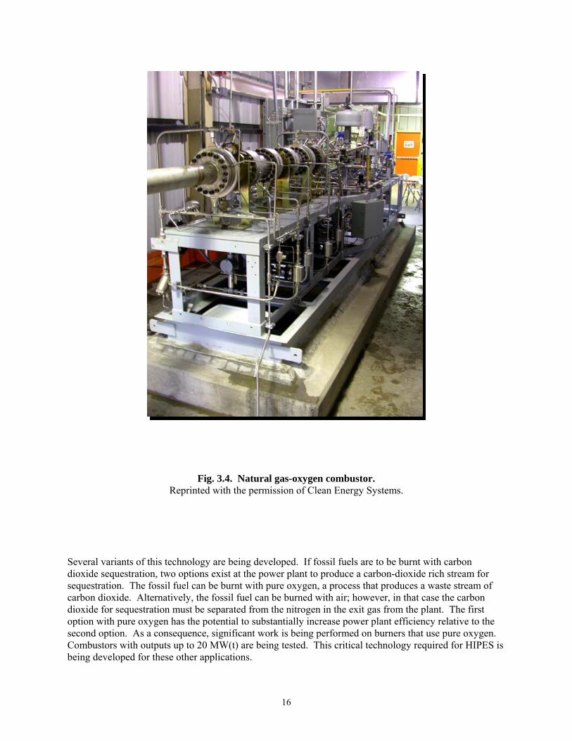
Fig. 3.3. HIPES high-temperature steam turbine system. Industrial programs are underway to develop advanced natural gas electric plants that use oxygen rather than air (Anderson et al., 2004). These programs are developing the technology that would be required for HIPES. Natural gas and oxygen are burnt to yield steam and carbon dioxide. This high-temperature gas mixture is fed to a very high temperature steam turbine. In these systems, the carbon dioxide will be removed from the condenser for carbon dioxide sequestration in oil fields while the recovery of heavy oil is increased. Figure 3.4 shows an experimental 20-MW(t) natural gas─oxygen combustor with a peak combustion temperature of 1760ºC and operational pressures from 2.07 to 10.34 MPa. The expectation is that advanced turbines will ultimately allow gas-turbine inlet temperatures near 1500°C. This technical option tolerates relatively impure hydrogen and oxygen; thus, any impurities from storage facilities should not be a significant constraint. Impurities from storage facilities are not expected when hydrogen and oxygen are stored in salt; however, impurities may be present if the storage facility is sited in several other types of geology.
16
Fig. 3.4. Natural gas-oxygen combustor. Reprinted with the permission of Clean Energy Systems.
Several variants of this technology are being developed. If fossil fuels are to be burnt with carbon dioxide sequestration, two options exist at the power plant to produce a carbon-dioxide rich stream for sequestration. The fossil fuel can be burnt with pure oxygen, a process that produces a waste stream of carbon dioxide. Alternatively, the fossil fuel can be burned with air; however, in that case the carbon dioxide for sequestration must be separated from the nitrogen in the exit gas from the plant. The first option with pure oxygen has the potential to substantially increase power plant efficiency relative to the second option. As a consequence, significant work is being performed on burners that use pure oxygen. Combustors with outputs up to 20 MW(t) are being tested. This critical technology required for HIPES is being developed for these other applications.
17
This type of plant has the potential for significantly lower capital costs than the natural gas combined-cycle plants [$570/kW(e)] discussed earlier—perhaps by as much as a factor of 2. Unlike the combined-cycle plant, there is no compressor to compress air to high temperatures and no boiler to convert water to steam. Only the high-temperature steam turbine with its condenser and the generator remain. Simultaneously, a major increase in the efficiency (55 to 70%) occurs by eliminating the compression of nitrogen in the air and the inefficiencies in transferring heat from the Brayton power cycle to the steam in the steam boiler. 3.2.3.2 HIPES Production of Electricity with Fuel Cells Hydrogen can be converted to electricity using fuel cells. Five classes of fuel cells, each with different characteristics, presently exist (EG&G Technical Services, Inc., and Science Applications International Corporation, 2002). A preliminary assessment (Forsberg, 2005a) based on near-term technologies indicates that the leading candidates for this application are alkaline and polymer fuel cells. These fuel cells have the best capabilities for rapid transient power operations, operate below 100ºC (thus avoiding the potential thermal fatigue of materials in high-temperature fuel cells), have potentially low costs, and have good performance with pure oxygen. Based on the existing knowledge, alkaline fuel cells appear to be superior for this application. Polymer fuel cells are being developed for transport applications because of their small volume—an important characteristic for vehicles, but not for HIPES. However, the very large research programs for vehicle fuel cells may lower the costs of polymer fuel cells and thus make them the preferred option. Alkaline fuel cells (Fig. 3.5) are one of the oldest fuel-cell technologies. A large experience base exists, and pure oxygen−hydrogen variants have been used for decades in the space program. The pure-oxygen alkaline fuel cells used in the space shuttle have an efficiency of ~60%. For large-scale industrial systems, the efficiencies may approach 70%, because there are no weight and size limitations. Recent reviews have summarized the status of this technology (EG&G Technical Services, Inc., and Science Applications International Corporation, 2002; McLean et al., 2002). Alkaline fuel cells have a five-layer structure: a gas chamber for hydrogen feed, an anode membrane, a liquid potassium hydroxide electrolyte, a cathode membrane, and a gas chamber for the oxygen feed. The overall chemical reactions are as follows: Anode reaction 2H2 + 4OH─ → 4H2O + 4e─ Cathode reaction O2 + 2H2O + 4e─ → 4OH─ Overall cell reaction 2H2 + O2 → 2H2O + electricity + heat The water is formed in the potassium hydroxide solution between the membranes. The potassium hydroxide solution is circulated to (1) improve transfer of hydroxide ions within the fuel cell and (2) remove heat and excess water.

18
04-096
H2 O2
2H2 + 4OH– →4H2O + 4e–
Anode
O2 + 2H2O + 4e–
→ 4OH–
Cathode
e–
T = 80-100º C
Water RemovalHeat Rejection
H2O
KOHSolution
Gas Flow Channel
ElectrodeCatalyst Layer
Gas Flow Channel
ElectrodeCatalyst Layer
Hydrogen Oxygen
Pump
OH–
H2 O2
2H2 + 4OH– →4H2O + 4e–
Anode
O2 + 2H2O + 4e–
→ 4OH–
Cathode
e–
T = 80-100º C
Water RemovalHeat Rejection
H2O
KOHSolution
Gas Flow Channel
ElectrodeCatalyst Layer
Gas Flow Channel
ElectrodeCatalyst Layer
Hydrogen Oxygen
Pump
OH–
Fig. 3.5. Alkaline fuel cell. Alkaline fuel cells have several advantages relative to other fuel-cell types: excellent performance using pure oxygen and hydrogen; no expensive materials such as platinum catalysts; scalability to large size; low-pressure, low-temperature operation; potentially low cost; and excellent capabilities for transient power operations (Ernst and Nerschook, 2004). The outstanding performance using pure oxygen and hydrogen is partly a consequence of the flowing potassium hydroxide electrolyte. Pure oxygen and hydrogen allow for very high power densities and lower cost systems; however, such high power densities require effective cooling of the fuel cell. The flowing electrolyte provides an efficient method to remove heat from the fuel-cell stack as fast as it is generated. Alkaline fuel cells have limitations for use in vehicles (e.g., low power density, the need for cleanup of the potassium hydroxide solution, and electrolytic poisoning of the fuel cell from carbon dioxide in air). However, these limitations do not apply to alkaline fuel cells within HIPES that are fed pure hydrogen and oxygen. For stationary applications, minimum cost per kilowatt electric and maximum efficiency, not size or weight, are the primary requirements. The processing of the hydroxide solution is a low-cost operation on a large scale. If HIPES uses pure oxygen, no carbon dioxide is present in the feed, a major constraint when using alkaline fuel cells with air as the oxidizer.

19
In the last several years, a renewed interest has emerged in alkaline fuel cells as a potentially lower-cost, more-efficient alternative to burning natural gas in gas-turbine combined-cycle plants to produce electricity. This renewed interest and the ongoing research and development are reducing the costs of these systems and facilitating the development of systems that are directly applicable to HIPES. Most of the earlier research and development relating to alkaline fuel cells was for aerospace and vehicle applications, in which weight is a major, and often the primary, design constraint. In contrast, the research and development work being preformed today is for land-based power applications, in which reducing the cost per unit power output and increasing the efficiency are the primary goals. One example is the development program of Cenergie Corporation PLC. Figure 3.6 is a photograph of one of the new Cenergie alkaline-fuel-cell stacks, while Fig. 3.7 is a simplified schematic of the internals of a modern alkaline-fuel-cell stack.
Fig. 3.6. Cenergie alkaline-fuel-cell stack. Reprinted with permission from Cenergie Corporation PLC.

20
Fig. 3.7. Schematic of interior of Cenergie alkaline-fuel-cell stack. Reprinted with permission from Cenergie Corporation PLC.
From an industrial perspective, a large-scale alkaline-fuel-cell facility has striking similarities to chlorine production facilities. Chlorine is used for water treatment, is produced on a massive scale, and is one of the largest sectors of the chemical industry. In a chlorine production facility, electricity is used in electrolytic cells to convert a sodium chloride brine solution to chlorine and sodium hydroxide. The facility includes large electrolytic cells, gas-handling systems for toxic gases, alkaline solution (sodium hydroxide) processing systems with heat removal, and electrical power conversion systems. A large alkaline-fuel-cell facility has many similarities to the chlorine facility [electrolytic cells, hazardous gas (oxygen rather than chlorine), alkaline solution processing systems with heat removal, etc.]. These similarities and the extensive knowledge concerning performance with oxygen may enable early development of conceptual designs and relatively reliable cost estimates for a HIPES facility based on alkaline fuel cells.

21
Traditional fuel-cell applications produce kilowatts to a few megawatts of energy. The application herein is for hundreds or thousands of megawatts of power when oxygen feed is used. No public studies of the costs of large-scale fuel-cell facilities have been undertaken. However, several economic factors have been identified that may drastically improve the fuel-cell economics for this application relative to other applications. • Oxygen feed. Pure oxygen feed (rather than air) will increase cell output by several hundred percent
(EG&G Technical Services, Inc., and Science Applications International Corporation, 2002) relative to air, with major reductions in capital costs. Simultaneously, a significant improvement in efficiency occurs. The size of the fuel-cell system is controlled by the oxygen electrode. Pure oxygen increases the gas-phase oxygen concentration at this electrode by a factor of 5 over that achieved via the use of air, with major reductions in the fuel-cell size. There is no nitrogen that acts as a diffusion barrier to slow the transport of oxygen to the electrode. Although this is a major advantage when using alkaline fuel cells, the technique may not be applicable to all fuel cells. High power densities imply significant cooling loads. While such cooling loads are easy to manage with a fuel cell that has a flowing electrolyte, they are difficult to manage with fuel cells such as proton exchange membrane (PEM) cells that have solid electrolytes.
• Higher-pressure operation. The storage caverns supply hydrogen and oxygen at high pressure. This
eliminates any pumping costs and favors operation above atmospheric pressure. Moderate pressures greatly reduce the size of auxiliary equipment such as piping and may allow reductions in the size of the fuel cell for a given power output.
• Manufacturing economics. A large fuel-cell complex allows efficiencies in the manufacture of
specific components such as the fuel-cell stacks. • Economics of scale. Large economics of scale are associated with buildings, electrical conversion
equipment, and gas-handling systems (compressors, pipes, valves, etc.). In this specific case, some understanding of the potential economics of scale is obtained by examining large chlorine production facilities. The scaling factor (Goossen et al., 2003) for chlorine plants has been estimated at 0.54; that is, increasing the size of the facility by a factor of 4 results in the capital cost of the larger facility being only 53% of that of the smaller facility per unit of capacity. Very large economics of scale exist in such a process.
3.2.4 Hydrogen and Oxygen Production HIPES reduces the capital costs of the equipment required to convert hydrogen to electricity and improves efficiency by using nuclear hydrogen and the co-product oxygen. While hydrogen can be shipped by pipeline, pipeline shipment of oxygen is significantly more expensive and challenging because of associated safety concerns. Similarly, the storage of oxygen may require a significant heat input. These factors imply co-siting of hydrogen-oxygen production systems, storage systems, and electrical production systems and favor nuclear-hydrogen production (Nuclear Energy Agency, 2005) or centralized solar production technologies such as solar power towers (Steinfeld, 2002). Co-siting (1) avoids the transport costs of hydrogen and oxygen and (2) provides a source of heat for heating the oxygen for safe storage. 3.2.5 Implications and Implementation of HIPES If an economic method is developed to better match renewable electricity production with consumer electricity demand, a major economic constraint for large-scale renewable electricity is removed and a major market for nuclear hydrogen is created. Renewables are capital-intensive low-operating-cost technologies that can produce economic electricity only if operated at full capacity but produce expensive electricity if operated at partial load or if traditional backup power is required when they are not operating.

22
This type of technology is particularly important for renewable energy sources such as wind (DeCarolis 2006). Peak wind conditions do not always match peak electric demand. Furthermore, as observed in Europe, short periods of low wind conditions have occurred over large areas. To ensure reliable electricity, either (1) the fraction of electricity from renewables must be limited to a small fraction of the total electric demand so that the rest of the system can provide electricity when needed or (2) backup electric power must be present. For electric renewables to provide a major fraction of the total electricity demand, very low capital cost backup electric power is required. In terms of commercialization, HIPES is an alternative to pumped-hydro facilities with the added capability of “storing” electricity for weeks or seasonally. Several utilities (Duke Power and the Tennessee Valley Authority) built nuclear plants and pumped-hydro facilities at the same time to store electricity from off-peak production to meet peak power demands. The same strategy can be used for HIPES. Because HIPES is a utility operation, a single customer exists for hydrogen production and consumption, thus greatly simplifying the commercialization of such a system. HIPES can potentially exist in two forms: (1) in association with a nuclear-hydrogen production or (2) as stand alone facility using electrolysis and electricity from the electrical grid. The second option has the potential economic penalty of requiring outside heat to heat oxygen for safe storage (or developing higher-temperature electrolysis cells to use the waste heat from electrolysis to heat oxygen). The required technologies are rapidly being developed. The next step to develop HIPES is a series of more-detailed engineering and economic studies that require the involvement of laboratories, utilities, the Electric Power Research Institute, and the potential equipment suppliers. Several utilities in the United States have major commitments to both wind energy and nuclear power. These utilities are the logical partners for such studies because they face the problem of integrating wind energy into their electrical systems. 3.3 LIQUID FUELS AND BIOMASS The second need of an energy system is energy for transportation. The transportation system is dependent upon liquid fossil fuels (gasoline, diesel, and jet fuel) because of the high energy density that makes these fuels easy to store and transport. The near-term transport fuel option with reduced greenhouse impacts is the use of biomass to make liquid fuels (Ragauskas et al., 2006). Retaining the use of liquid fuels avoids the storage and transport challenges of alternative transport fuels. Biomass is used today to produce liquid fuels such as alcohol by fermentation. In this process, no greenhouse gas impacts occur if all the energy in the production process is from biomass, because the carbon dioxide used to make the biomass comes from the atmosphere. However, the actual greenhouse gas releases are strongly dependent upon the specific technologies (Farrell 2006). There is insufficient biomass to meet the world’s demand for liquid fuels (Perlack et al., 2005). Current estimates (Koonin, 2006) indicate that with plausible technology developments, biofuels could supply about 30% of the global liquid-fuel demand. A major constraint is that only a fraction of the carbon in the biomass and a fraction of the energy in the biomass become liquid fuel. For example, the conversion of corn to ethanol results in roughly one-third of the carbon from the original corn in the ethanol, one-third in the by-product animal feed, and one-third in the form of carbon dioxide released to the atmosphere from respiration of the yeast.

23
The biomass limitation can be greatly reduced if reliable hydrogen is available from bulk hydrogen storage facilities when needed. The alternative liquid-biomass future is to consider biomass first as a source of carbon to make liquid fuels and secondarily as an energy source (Forsberg, 2005c). With appropriate processing (Sect. 4), all of the carbon in the biomass becomes part of the liquid fuel and the energy value of the liquid fuel can be increased by a factor of 2 to 3. The increased liquid-fuel production is a consequence of two factors. • Full carbon utilization. All the carbon is converted to a liquid fuel, with no carbon dioxide release to
the atmosphere from converting biomass to liquid fuel. • Higher-energy fuel. The production of a liquid hydrocarbon fuel, rather than a partly oxidized fuel
such as alcohol, further increases the fuel value. Biomass contains significant quantities of oxygen and can be thought of as a partially oxidized hydrocarbon. It is a complex mixture containing cellulose, lignins, and hemicellulose. In assessing fuel efficiencies, cellulose (C6H10O5), the primary component, can be used to represent biomass as an energy source, while hexane (C6H14) can be used to represent hydrocarbons as an energy source. The energy value of hexane per mole is 50% greater than that of cellulose. Thus, the production of a hydrocarbon fuel from biomass by adding hydrogen during the fuel production process maximizes the energy value in the liquid fuel of each carbon atom collected by the biomass compared with the production of an alcohol as the fuel.
Several characteristics of nuclear hydrogen couple well with this fuel option. Nuclear hydrogen can deliver large quantities of hydrogen directly from storage or production as needed, while biomass fuel production will likely have a somewhat seasonal characteristic. Second, biomass production facilities will be relatively large plants in rural areas. The demand for hydrogen is situated at a few sites, with a large demand per site, thus minimizing the hydrogen pipelines and avoiding the construction of pipelines in expensive, high-population-density areas. Little work has been conducted on combined hydrogen biomass systems where hydrogen is supplied from an outside source to boost liquid fuel production. The near-term research and development requirements are to better understand this potentially synergistic system. This includes the important technical question of whether biomass can be directly converted to a hydrocarbon fuel by direct hydrogenation rather than the indirect processes (e.g., Fischer-Tropsch) used for conversion of fossil fuels such as coal and natural gas to liquids. The traditional indirect processes convert the carbon feed to a mixture of carbon monoxide and hydrogen that is then converted into a liquid fuel. In theory, direct hydrogenation processes have potentially much lower costs. Relatively pure materials from biomass (such as glycerol from plant oils) have been directly converted into hydrocarbon fuels. However, this is not the case with more complex biomass materials.

24
Blank page

25
1900 1920 1940 1960 1980 20000
10
20
30
40
50
60
0
10
20
30
40
50
60
Dis
cove
ries
(bill
ion
bbl/y
ear)
Prod
uctio
n (b
illio
n bb
l/yea
r)
Discovery
Consumption
1900 1920 1940 1960 1980 20000
10
20
30
40
50
60
0
10
20
30
40
50
60
Dis
cove
ries
(bill
ion
bbl/y
ear)
Prod
uctio
n (b
illio
n bb
l/yea
r)
Discovery
Consumption
4. FOSSIL-LIQUIFACTION NUCLEAR-HYDROGEN SYNERGIES 4.1 LIQUID-FUEL SYSTEM CONSIDERATIONS Liquid fuels (gasoline, diesel, and jet fuel) have major advantages as transport fuels: a high energy density per unit volume and mass, ease of storage, and ease of transport. However, there are major disadvantages: crude oil is increasingly expensive and of value to the petrochemical industry; most of the world’s crude oil comes from politically unstable parts of the world; and burning of hydrocarbons releases greenhouse gases to the atmosphere. Liquid fuels can be produced from other carbon feedstocks (heavy oil, tar sands, oil shale, coal, biomass, and other carbon sources) using nuclear energy to produce (1) hydrogen and oxygen from water and (2) heat as required. The use of nuclear energy in this role has the potential to reduce costs and minimize greenhouse gas emissions in the production of liquid fuels. About 40% of the U.S. energy demand is met by petroleum that is converted primarily to liquid fuels. However, the world is rapidly exhausting its resources of the light crude oils used to make liquid fuels (Fig. 4.1). To meet our transportation needs, a replacement for crude oil is required. As oil becomes scarce, liquid fuels will be produced with increasing frequency from natural gas (gas to liquids) and from heavier feedstocks such as heavy oil, tar sands, oil shale, and coal. With current technology, this conversion process can be summarized as follows: Carbon-based feedstock + Water + Oxygen (O2) → Liquid fuels + Carbon dioxide (CO2) (1)
Fig. 4.1. Rate of discovery and consumption of crude oils vs time (Wells, 2005).

26
Liquid fuels today are made from heavy oils (many countries), tar sands (Canada), and coal (South Africa). In a refinery, heavy oils are converted to liquid fuels by increasing the hydrogen-to-carbon ratio of the feedstock to that of liquid fuels (hydrogen-to-carbon ratio of 1.5 to 2). This increase requires either (1) thermal cracking to remove carbon or (2) hydrogenation to add hydrogen. The carbon from thermal cracking is ultimately released to the atmosphere as CO2. Traditionally, hydrogen is produced by steam reforming of fossil fuels, a process that produces hydrogen and CO2, with the latter being released to the atmosphere. If we switch from light crude oils to alternative hydrocarbon feedstocks to produce liquid fuels, the CO2 emissions per vehicle mile traveled will increase, as is shown in Fig. 4.2. For some options such as the production of liquid fuels from coal, the CO2 emissions per mile of vehicle travel will double. In Fig. 3.2 it is assumed that the natural gas and coal are converted to diesel fuel by the classical three-step gasification, water-gas shift, and Fischer-Tropsch synthesis processes. Traditional refining is assumed to produce diesel fuel from crude oils. Because of the expected impacts of greenhouse gases on climate, serious limitations may exist in using these established technologies in their traditional form to produce liquid fuels from alternative feedstocks.
Illinois #6 Coal Baseline
Pipeline Natural Gas
Wyoming Sweet Crude Oil
Venezuelan Syncrude
0
200
400
600
800
1000
1200
Gre
enho
use
Impa
cts
(g C
O2-
eq/m
ile in
SU
V)
Conversion/RefiningTransportation/Distribution
End Use CombustionExtraction/Production
Business As Usual
Using Fuel
Making and
Delivering of Fuel
(Fisher-TropschLiquids)
(Fisher-TropschLiquids)
Source of G
reenhouse Impacts
Fig. 4.2. Equivalent carbon dioxide releases per SUV vehicle mile for diesel fuel produced from different feedstocks (Marano and Ciferno, 2001).

27
The increased CO2 emissions from these alternative processes are a consequence of using the carbon feedstock for three purposes within the processes: • to provide carbon for the liquid fuel; • to provide energy to operate the conversion process, including oxygen production; and • to serve as a reducing agent for the production of hydrogen to produce the liquid fuel. Alternatively, if economic hydrogen is available from non-greenhouse-emitting sources and the energy for the fuel processing does not release greenhouse gases to the atmosphere, the atmospheric carbon CO2 emissions from liquid-fuel production per vehicle mile (unit of liquid fuel) can be lower than that available today from light crude oil. With nuclear hydrogen, this conversion process can become the following: Carbon-based feedstock + Water + Nuclear energy → Liquid fuels (2) When nuclear energy is used (reaction 2), no CO2 is released from the fuel production process. All the carbon is incorporated into the fuel, and the carbon in the feedstock is not used as an energy source in the liquid-fuel production process. Carbon dioxide is thus released only from the burning of the liquid fuels. The option of using nuclear energy to assist liquid-fuel production was first examined in the 1970s. At that time, the incentives were the shortage of oil caused by the Arab oil embargo and the potential for the production of lower-cost hydrogen. These same incentives exist today plus the new incentive to minimize greenhouse gas emissions. This section examines the options and the potential synergisms between nuclear and fossil energy that may ultimately provide strong economic and environmental reasons for using nuclear hydrogen in liquid-fuel production. • Coproduction of hydrogen and oxygen. All of the nuclear-hydrogen production technologies use
water as a feedstock and thus produce hydrogen and by-product oxygen. Many of the processes to produce liquid fuels from alternative feedstocks require hydrogen and O2 (see Sect. 4.2). However, oxygen is expensive to produce both in terms of capital and energy costs with traditional oxygen production costs between $40 and $50 per ton.
• Site independence. There are increasing incentives to reduce greenhouse gas emissions─including
the possibility of taxes on CO2 emissions or requirements to reduce emissions. If fossil fuels are used in the liquid-fuel production process as an energy source or to manufacture hydrogen, large quantities of CO2 will be produced. It may be feasible to sequester this CO2 in certain types of geological structures. However, in most cases the carbon feedstocks (tar sands, shale oil, coal, etc.) will not be collocated next to suitable geological structures for CO2 sequestration. Either (1) liquefaction plants must be located next to CO2 sequestration sites with shipments of carbon feedstocks or (2) CO2 must be transported to sequestration sites. Significant costs are associated with either option. In contrast, nuclear plants require only 30 to 50 tons of fuel a year. Unlike other sources of energy, nuclear plants can be built almost anywhere, without consideration of the cost of fuel transport. Thus, nuclear plants can be collocated with feedstocks and fuel production plants.

28
4.2 LIQUIFACTION PROCESSES 4.2.1 Process Options Multiple processes are used for the production of liquid fuels using nuclear hydrogen. The fuel production processes can be divided into three categories. • Indirect processes. Carbon feedstocks are converted to syngas [a mixture of hydrogen and carbon
monoxide (CO)], and the syngas is subsequently converted to liquid fuels. • Direct processes. Carbon feedstocks such as coal are directly hydrogenated. • Other. These are processes designed for a specific feedstock with specific characteristics. The best-
known examples are the processes that convert shale oil to liquids. Indirect processes were chosen for our initial examination based on several considerations.
• Feedstock availability. Because indirect processes can start with any carbon source and produce
liquid fuels, they are the most versatile. • Industrial status. Indirect processes are today the preferred routes to liquid-fuel production. All
current and planned plants that convert coal to liquid fuels plants use indirect processes. • Product mix. Improvements in the indirect processes have allowed the production of liquid fuels that
better match the market needs and minimize the need for additional refining operations. • Clean fuel. The indirect processes can produce extremely clean fuels relative to liquid fuels produced
via crude oil or other liquefaction processes. This is a consequence of two factors: (1) it is relatively inexpensive to clean syngas mixtures to remove sulfur, heavy metals, and other impurities; and (2) the catalysts used to produce liquid fuels from syngas are intolerant of many impurities, thus necessitating the use of clean syngas.
4.2.2 Fischer-Tropsch Processing Fischer-Tropsch is the most widely used indirect method for the production of liquid fuels. The Fischer-Tropsch process is described in the following subsections, and methods for integration into a nuclear coal-liquefaction plant are discussed. More-detailed studies are required to understand the preferred options. 4.2.2.1 Chemistry Three major reactions occur in production of liquid fuels from carbon sources (coal, etc.) using the indirect Fischer-Tropsch liquefaction process: Oxidation of carbon: 2C + O2 → 2CO (3) Water-gas-shift reaction: CO + H2O ↔ CO2 + H2 (4) Fischer-Tropsch: (n/2 + m)H2 + mCO → CmHn + mH2O (5) The overall reaction converts carbon, oxygen, and water into liquid fuels and CO2. The major process operations (Fig. 4.3) are described with coal as the feedstock.

29
Air Separation
Sulfur Recovery
Gasification SyngasTreatment
Coal Preparation
Sulfur Guard Bed
CO2Removal
Dehydration/ Compression
SyngasConversion
(FT)
Hydrogen Recovery
Product Upgrading
AutothermalReforming
Hydrogen Recovery
SLAG
Vapor
Steam Oxygen
SULFUR
FT LIQUIDFUELS
HydrogenRecycle Gas
Liquid Hydrocarbons
COAL
Oxygen
AIR
Syngas
CARBON DIOXIDE
Coal Gasification
Liquid Fuel Production
Oxygen
NuclearCoal
Shift Converter Hydrogen
Carbon Dioxide
Fig. 4.3. Nuclear coal liquefaction and coal liquefaction by the indirect coal-gasification Fischer-Tropsch process.
Syngas Production (Gasifier) The first step is the production of syngas (a mixture of hydrogen, CO, and other gases) from the carbon source, water, and oxygen. Chemical reactions 3 and 4 occur in the gasifier. Depending upon temperature, pressure, and feed composition, some mixture of hydrogen, CO, CO2, and water will be produced as the raw syngas. The carbon oxidation process (reaction 3) is highly exothermic and can be considered a one-way process. The water-gas-shift reaction (reaction 4) is an equilibrium reaction in which the degree of completion of the reaction is strongly sensitive to temperature and gas composition. The feedstock for reaction 3 can be almost any carbon-containing material. Gasifiers currently operate on coal, petrocoke, garbage, natural gas, biomass, and a wide variety of other feeds.

30
Fischer-Tropsch Liquid-Fuel Production (Syngas Conversion) For production of liquid fuels, syngas is fed to a Fisher-Tropsch conversion reactor that produces the liquid fuel (CmHn). Reactions 4 and 5 occur in the Fisher-Tropsch conversion process. The choice of pressure, temperature, residence time, and feed gas composition determines the products. Nuclear Syngas Fisher-Tropsch Liquid-Fuel Production The nuclear variant involves supplying oxygen for the gasification step and hydrogen to avoid the need for the water-shift reaction (reaction 4) for hydrogen production. In practice, CO2 is produced in the process, thus creating the need to recycle that CO2 back to CO by the reverse-water-shift reaction. 4.2.2.2 Flowsheet The plant is divided into two sections: coal gasification and liquid-fuel production. Modifications required for a nuclear coal-liquefaction plant are shown by dotted lines in Fig. 4.3 and in italic text in the description below. Coal Gasification Coal preparation. The coal is ground. Air separation. High-purity oxygen is produced. For conventional plants, oxygen is obtained from air using standard cryogenic air-separation techniques. For a nuclear coal-liquefaction plant, the oxygen is produced from the splitting of water in the nuclear-hydrogen plant. Gasification. Coal with a carrier fluid is combined with oxygen and fed into the gasifier, a process that creates syngas (chemical reactions 3 and 4). If a Shell gasifier is used, the carrier is CO2 gas. If a Texaco gasifier is used, the carrier is water. This operation includes high-temperature gas cooling, slag handling, and solid waste handling. Syngas treatment. This is a set of purification steps that remove sulfur and other compounds. Sulfur recovery. This process converts the various sulfur compounds from syngas treatment into sulfur for sale or disposal. Fisher-Tropsch Conversion Syngas conversion (Fischer-Tropsch). This reactor converts the syngas mixture (primarily CO and hydrogen) into a liquid-fuel stream and a gas stream via reactions 4 and 5. Carbon dioxide removal (gas processing). The CO2 is selectively removed from the off-gas. If a Shell gasifier is used, a fraction of the stream is sent back to the gasifier to act as a carrier gas to bring the coal into the gasifier. The remainder of the CO2 is then released to the atmosphere. In a nuclear coal-liquefaction facility, the excess CO2 is recycled. Options include (1) the combination of CO2 with the hydrogen in a shift reactor (reaction 4) to produce CO and water, (2) recycle to the gasifier with added hydrogen, and (3) use of the Fischer-Tropsch reactor by recycle of CO2 with added hydrogen. Dehydration/Compression (gas processing). The moisture is removed from the gas stream and subsequently compressed.

31
Hydrocarbon recovery (gas processing). Useful hydrocarbons are recovered and sent to the product-upgrade system. Hydrogen recovery (gas processing). Hydrogen is recovered from the gas stream, which is then reheated with the hot liquid from the syngas conversion step. Product upgrading. The product-upgrading section is a simplified refinery that separates and converts the Fischer-Tropsch products into gasoline, diesel, and jet fuel. Autothermal reforming. The remaining gases (CH4, C2H2, and C2H6) are converted to syngas and sent back to the syngas conversion step. This requires the input of steam and oxygen. In a nuclear coal-liquefaction plant, the oxygen is produced by the nuclear-hydrogen plant. 4.2.3 Research and Development Needs An optimized flowsheet would likely result in a variety of changes in parts of the flowsheet and may add the hydrogen and recycled CO2 at different locations within the plant. Detailed studies are required to understand how the flowsheets would be modified and the economic benefits of such changes. Foreign proprietary studies are under way, but no results have been published. Separate studies are required to evaluate using a nuclear reactor for hydrogen, oxygen, and heat. If nuclear hydrogen and oxygen are supplied to a coal liquefaction plant, gas storage facilities can provide a buffer between the two plants so that they can be operated independently of one another. The shutdown of the reactor for refueling would not impact the coal liquefaction plant. In principle, providing high-temperature heat from a reactor has the potential to further reduce the cost of coal liquefaction. However, if heat is supplied in such a manner the reactor is tightly integrated into the coal liquefaction plant. Such integration creates a separate set of operational issues that must be addressed. 4.3 OTHER LIQUEFACTION PROCESSES The implications of nuclear hydrogen for other liquefaction processes are being examined. However, many other processes (direct liquefaction, flash heating of coal for liquids recovery, etc.) produce high-carbon by-product streams. If these other processes are adapted, indirect liquefaction is likely to be used to convert these secondary carbon-rich product streams to liquid fuels. 4.4 FUTURE FUEL TRANSITIONS The development of a nuclear-hydrogen coal-liquefaction system allows for the long-term evolution to a system that has limited or no greenhouse gas impacts. • Tar sands, coal, and shale oil. With these feedstocks, a nuclear-hydrogen liquid-fuel system can
limit greenhouse gas emissions to those from burning the clean fuel. For tar sands and shale oil, the extraction processes are also major energy users; thus, nuclear heat would also be required for the extraction processes. Limited work has been done on using nuclear heat for shale oil recovery (Forsberg 2006a) and tar sands recovery (Finan et al., 2006).
• Garbage and sewage solids. Society produces numerous carbon-containing wastes—many of which
were made originally from fossil fuels. Ultimately, the carbon in most of these wastes is oxidized by

32
burning or biodegradation in landfills, with the CO2 released to the environment. If these feedstocks are used for liquid-fuel production, no additional greenhouse gas emissions result beyond what would ultimately occur via the oxidation of these waste streams.
• Biomass. Biomass is used today to produce liquid fuels such as alcohol by fermentation. Because the
CO2 used to make the biomass comes from the atmosphere, no greenhouse gas impacts result. If the biomass is directly converted into liquid fuels via Fischer-Tropsch or a similar process with nuclear hydrogen, all the carbon is incorporated into liquid fuels. With this option, biomass is used primarily as a carbon source, not an energy source. The quantities of liquid fuels measured in terms of energy value increase by factor of 3 or more per unit of biomass input.
• Air. Liquid fuels can be made from hydrogen and CO2 extracted from (1) the atmosphere or (2) the
ocean. A modified Fischer-Tropsch synthesis process is used. The hydrogen is used (1) as a feedstock to make the liquid fuels and (2) as an internal energy source to drive the process of producing the fuel. Because the CO2 is recovered from the atmosphere or seawater, no greenhouse impacts occur. About 80% of the total energy input required to produce the liquid fuel is used to produce the hydrogen. Carbon dioxide extraction from air or water is not the primary energy cost.
The direct production of liquid fuels from air and water is the ultimate option for liquid-fuel production. This option was initially investigated in the 1970s (Steinberg 1977). There has been renewed recent interest in the concept (Forsberg, 2006c, Schultz 2006, Bogart 2006) for both commercial liquid-fuel production and military fuel production, where a nuclear-powered tanker makes aviation and diesel fuel for naval ships and thus eliminates the logistic challenges of fueling aircraft carriers and other naval vessels. Regardless of whether it is implemented, for several reasons, this is an important endpoint option for liquid-fuel production. • Liquid-fuel impacts. This option using existing technologies provides unlimited liquid fuels with no
greenhouse impacts as long as the hydrogen and energy come from non-greenhouse-emitting energy sources.
• Ultraclean liquid fuel. With this approach, the feedstocks contain no sulfur or heavy metals; thus,
ultraclean liquid fuels are produced. • Hydrogen economy. From an economic perspective, this technology places an upper economic limit
on the allowable costs for using hydrogen directly as a transport fuel compared with those for using liquid fuels. The production costs of liquid fuels using hydrogen and CO2 from the atmosphere are significantly higher than those for producing hydrogen. However, the costs of distributing and storing liquid fuels are much lower than those for distributing and storing hydrogen. Either approach can provide the fuel for the transport system without increasing atmospheric greenhouse concentrations. Economics will likely determine the preferred option.

33
5. OTHER SYNERGIES This report has discussed potential synergistic connections between nuclear hydrogen, renewable energy sources, and the production of liquid fuels from coal. A variety of additional second-order synergisms exist between nuclear-hydrogen systems and other energy and environmental systems that use the by-product oxygen for different applications. Because nuclear hydrogen has the unique characteristic of producing by-product oxygen on a large scale, the use of that oxygen for beneficial purposes may have a significant impact on the total economics. • Use of fossil fuels. Because of concerns about potential changes in climate from greenhouse gas
emissions, there is increased research on sequestration of carbon dioxide emitted from fossil-fuel electric generating plants. There are two methods to extract a relatively pure stream of carbon dioxide for sequestration from a fossil energy plant. The first option is to extract the carbon dioxide from the nitrogen and other gases in the off-gas. The second option is to use pure oxygen to burn the fossil fuel and produce a relatively pure exhaust stream of carbon dioxide. Ongoing investigations indicate that burning fossil fuels with oxygen for electricity production is more efficient than burning at traditional fossils with air. The capital costs may also be lower—excluding the cost of the oxygen separation plant. If low-cost oxygen is available, there is potentially an economic synergism between nuclear-hydrogen production with the by-product oxygen used for fossil-fuel electricity production with or without sequestration of the carbon dioxide. In the United States there are a number of utility sites with collocated nuclear and fossil units. At such collocated sites such options may become attractive.
• Water and waste treatment. A wide variety of urban and industrial water and wastewater treatment
operations (e.g., paper mills) use air to provide oxygen to oxidize the organics in the wastewater. There has been substantial research on the use of oxygen rather than air as an oxidant because it drastically reduces the plant size. In a few specialty applications where land is limited or other constraints are present, oxygen is used rather than air. If a nuclear-hydrogen system is deployed, the by-product oxygen may have major use in the treatment of various waste streams. For some facilities such as sewage-sludge-treatment facilities, the sludge can be moved near the nuclear-hydrogen facility to collocate the oxygen consumer with the oxygen producer.

34
Blank page

35
6. CONCLUSIONS AND RECOMMENDATIONS The production of hydrogen using nuclear energy (nuclear hydrogen) has a several characteristics: the raw material is water, hydrogen and oxygen are produced, the scale of operations is very large, and low-cost heat is available from the nuclear reactors. The high-volume centralized production couples with low-cost centralized storage of hydrogen and oxygen in underground facilities. This unique combination of characteristics makes possible synergies between nuclear hydrogen and (1) renewable energy systems producing electricity or liquid fuels and (2) fossil gasification and liquefaction systems. These systems, which combine nuclear hydrogen with renewable and fossil energy systems, have potentially lower costs, fewer technical barriers, and smaller environmental impacts than comparable nuclear-only, renewable-only, or fossil-only systems. As such, these systems may become the early markets for nuclear hydrogen because of the added benefits that nuclear hydrogen brings to these applications relative to those for the production of hydrogen as a fuel. This study is an initial assessment to identify and characterize these systems. Further research and development is warranted in three cases. • Hydrogen Intermediate and Peak Electrical Systems. HIPES potentially offers unique advantages as
a first market for nuclear hydrogen. The customers are the same utilities that own nuclear power plants, and the infrastructure requirements are very limited. This significantly reduces the technical and institutional barriers to introducing a new technology. Ongoing technological developments for other applications are developing the base technologies required for HIPES. The critical needs to advance this option are (1) system studies that include laboratories, users, and equipment manufacturers to optimize the system; (2) validation of the large-scale storage of compressed hydrogen in multiple geological media in addition to salt; and (3) development of large-scale underground oxygen storage technologies that address the critical safety issues. Several new technologies that are being developed for other applications, such as oxygen-fuel steam turbines and advanced industrial fuel cells, are directly applicable to HIPES and create the potential for cooperative programs.
• Liquid fuels from biomass. The liquid-fuel yield per unit biomass can be dramatically increased by
the input of external hydrogen. Given the strong national emphasis on producing liquid fuels from biomass and the limits of biomass, there are strong incentives to maximize liquid-fuel yield. The critical needs are to understand the gains and costs in using hydrogen to boost the liquid-fuel yield per ton of biomass input. This may include a critical need to identify and develop more efficient technologies for upgrading biomass to liquid fuels using hydrogen.
• Liquid fuels from coal and other carbon sources. The production of liquid fuels from coal is an
industrial technology. The critical research need is to understand the economic and technical implications of using outside sources of hydrogen and oxygen in this process. This requires a reoptimization of the flowsheets for the changing conditions.

36
Blank page

37
7. REFERENCES Anderson, R. E., S. E. Doyle, and K. L. Pronske, 2004, “Demonstration and Commercialization of Zero-Emission Power Plants,” 29th International Technical Conference on Coal Utilization & Fuel Systems, Clearwater, Florida, April 18–22. Bogart, S. L., K. Schultz, L. Brown, and B. Russ, 2006, “Production of Liquid Synthetic Fuels from Carbon, Water, and Nuclear Power on Ships and at Shore Bases for Military and Potential Commercial Applications,” Paper 6007, CD-ROM, Embedded topical: 2006 International Congress on the Advances in Nuclear Power Plants (ICAPP06), 2006 American Nuclear Society Annual Meeting, Reno, Nevada, June 4–8, 2006, American Nuclear Society, La Grange, Illinois. DeCarolis, J. F., and D. W. Keith, 2006, “The Economics of Large-scale Wind Power in a Carbon Constrained World,” Energy Policy, 34, 395–410. EG&G Technical Services, Inc., and Science Applications International Corporation, 2002, Fuel Cell Handbook, 6th ed., DOE/NETL-2002/1179, U.S. Department of Energy, Morgantown, West Virginia, November. Ernst, W., and J. Nerschook, 2004, “Telecoms Networks: The New Rules of Power,” The Fuel Cell Review, 25–28 (June/July). Farbman, G. H., 1976, The Conceptual Design of an Integrated Nuclear Hydrogen Production Plant Using the Sulfur Cycle Water Decomposition System, NASA-CR-134976, Westinghouse Electric Corporation, Pittsburgh, Pennsylvania, April. Farrell, A. E., R. J. Plevin, B. T. Turner, A. D. Jones, M. O’Hare, and D. M. Kammen, 2006, “Ethanol Can Contribute to Energy and Environmental Goals,” Science 311, 506–508 (January 27). Finan, A.E., K. Niu, and A. C. Kadak, 2006, “Nuclear Technology & Canadian Oil Sands: Integration of Nuclear Power with In-Situ Oil Extraction,” Paper 6442, CD-ROM, Embedded topical: 2006 International Congress on the Advances in Nuclear Power Plants (ICAPP06), 2006 American Nuclear Society Annual Meeting, Reno, Nevada, June 4–8, 2006, American Nuclear Society, La Grange, Illinois. Foh, S., M. Novil, E. Rockar, and P. Randolph, 1979, Underground Hydrogen Storage Final Report, BNL-51275, Brookhaven National Laboratory, Upton, New York. Forsberg, C. W., 2005a, Nuclear Hydrogen for Peak Electricity Production and Spinning Reserve, ORNL/TM-2004/194, Oak Ridge National Laboratory, Oak Ridge, Tennessee, January. Forsberg, C.W., 2005b, “Nuclear Hydrogen for Production of Liquid Hydrocarbon Transport Fuels,” Paper 581a (CD-ROM), Proceedings of the 2005 American Institute of Chemical Engineers Fall Meeting, October 30–November 4, 2005, Cincinnati, Ohio, American Institute of Chemical Engineers, New York, October. Forsberg, C. W., 2005c, “The Hydrogen Economy Is Coming, The Question Is Where?” Chemical Engineering Progress 101(12), 20–22 (December).

38
Forsberg, C. W. 2006a, “High-Temperature Reactors for In Situ Recovery of Oil from Oil Shale,” Paper 6104, CD-ROM, Embedded topical: 2006 International Congress on the Advances in Nuclear Power Plants (ICAPP06), 2006 American Nuclear Society Annual Meeting, Reno, Nevada, June 4–8, 2006, American Nuclear Society, La Grange, Illinois. Forsberg, C. W. 2006b, “Economic Implications of Peak vs. Base-Load Electric Costs on Nuclear Hydrogen Systems,” CD-ROM, Proceedings of the American Institute of Chemical Engineers Fall Meeting, San Francisco, California, November 12–17, 2006, American Institute of Chemical Engineers, New York. Forsberg, C. W., 2006c, “Hydrogen Markets: Implications for Hydrogen Production Technologies,” International Journal of Hydrogen Energy (in press). Goossen, J. E., E. J. Lahoda, R. A. Matzie, and J. P. Mazzoccoli, 2003, “Improvements in the Westinghouse Process for Hydrogen Production,” Proceedings of Global 2003, Embedded Topical within 2003 American Nuclear Society Winter Meeting, November 16B20, 2003, New Orleans, Louisiana. Haldor Topsoe A/S. 2005, “Topsoe Awarded Contract for Largest Hydrogen Production Capacity in the World for KNPC, Kuwait,” press release, Lyngby, Denmark, August 3. Koonin, S. E., 2006, “Getting Serious About Biofuels,” Science 311(5760), 435 (January 27). Marano, J. J., and Ciferno, J. P., 2001, Life-Cycle Greenhouse-Gas Emissions Inventory for Fischer-Tropsch Fuels, Energy, and Environmental Solutions, LLC, for the U.S. Department of Energy National Energy Technology Laboratory, Pittsburgh, Pennsylvania. Mazza, P., and R. Hammerschlag, 2004, Carrying the Energy Future, Comparing Hydrogen and Electricity for Transmission, Storage, and Transportation, Institute for Lifecycle Environmental Assessment, Seattle, Washington, June. McLean, G. F., T. Niet, S. Prince-Richard, and N. Djilal, 2002, “An Assessment of Alkaline Fuel Cell Technology,” International Journal of Hydrogen Energy 27, 507–526. Miller, A. I., and R. B. Duffey, 2003, “Meeting the Near-Term Demand for Hydrogen Using Nuclear Energy in Competitive Power Markets,” Proceedings of the Second Information Exchange Meeting on Nuclear Production of Hydrogen, Argonne National Laboratory, Argonne, Illinois, October 2–3, 2003, OECD Nuclear Energy Agency, Paris, France, March. National Academy of Sciences, 2004, The Hydrogen Economy: Opportunities, Costs, Barriers, and R&D Needs, National Academies Press, Washington, D.C. Nuclear Energy Agency, 2003, Proceedings of the OECD/NEA Second Information Exchange Meeting on Nuclear Production of Hydrogen, OECD Nuclear Energy Agency, Paris, France. Nuclear Energy Agency, 2005, Proceedings of the Third Information Exchange Meeting on Nuclear Production of Hydrogen, Atomic Energy Research Institute, Oarai, Japan, October 5–7, 2005, OECD Nuclear Energy Agency, Paris, France. Ondrey, G. 2006, “Hydrogen: The Real Action Is Today,” Chemical Engineering 113(2), 28 (February).

39
Perlack, et al., 2005, Biomass as Feedstock for a Bioenergy and Bioproducts Industry: The Technnical Feasibility of a Billion-Ton Annual Supply, U.S. Department of Energy, Washington D.C. (April). Ragauskas, A. J., et al. 2006, “The Path Forward for Biofuels and Biomaterials,” Science 311, 484–489 (January 27). Schultz, K., et al., 2006, “Hydrogen and Synthetic Hydrocarbon Fuels—A Natural Strategy” CD-ROM, 17th Annual U.S. Hydrogen Conference, Long Beach, California, March 12–16, 2006. Shiozawa, S., et al. 2000, “Present Status of JAERI=s R&D on Hydrogen Production Systems in HTGR,” Nuclear Production of Hydrogen: First Information Exchange Meeting, October 2B3, 2000, Paris, France, OECD Nuclear Energy Agency, Paris, France. Steinfeld, A. 2002, “Solar Hydrogen Production via a 2-Step Water-Splitting Thermochemical Cycle Based on Zn/ZnO Redox Reactions,” International Journal of Hydrogen Energy 27, 611–619. Steinberg, M, and V. Dang, 1977, “Production of Synthetic Methanol for Air and Water Using Controlled Thermonuclear Reactor—I. Technology and Energy Requirement,” Energy Conversion 17, 97–112, Pergamon Press. Thompson, J. M. 1997, “U.S. Underground Storage of Natural Gas in 1997: Existing and Proposed,” Natural Gas Monthly, United States Energy Information Administration, Washington, D.C., September. U.S. Department of Energy. 1995, The Value of Underground Storage in Today’s Natural Gas Industry, DOE/EIA-0591(95), U.S. Energy Information Agency, Washington, D.C. U.S. Department of Energy, 2005, Table 38 in Assumptions for the Annual Energy Outlook 2005, U.S. Energy Information Administration, Washington, D.C. U.S. Department of Energy, 2006, “H2A Model,” Hydrogen, Fuel Cells & Infrastructure Technologies Program, Energy Efficiency and Renewable Energy, Washington, D.C. Wells, P., 2005, “Oil Supply Challenges—1: The Non-OPEC Decline,” Oil and Gas Journal, 20–28 (February 21).

40
Blank page

ORNL/TM-2006/114
INTERNAL DISTRIBUTION 1. T. R. Armstrong ([email protected]) 2. S. J. Ball ([email protected]) 3. J. L. Binder ([email protected]) 4. M. A. Brown ([email protected]) 5. D. C. Christensen ([email protected]) 6. W. R. Corwin ([email protected]) 7. C. W. Forsberg ([email protected] 8. S. R. Greene ([email protected]) 9. R. A. Hawsey ([email protected]) 10. R. F. Holdaway ([email protected]) 11. D. T. Ingersoll ([email protected]) 12. B. J. Kirby ([email protected])
13. J. D. Kueck ([email protected]) 14. G. E. Kulynych ([email protected]) 15. P. N. Leiby ([email protected]) 16. G. T. Mays ([email protected]) 17. G. E. Michaels ([email protected]) 18. D. L. Moses ([email protected]) 19. C. V. Parks ([email protected]) 20. J. E. Rushton ([email protected]) 21. D. F. Williams ([email protected]) 22. Office of Technical Information and
Classification ([email protected])
EXTERNAL DISTRIBUTION
23. H. E. Clark, U.S. Department of Energy, Oak Ridge Field Office, Oak Ridge, Tennessee 37831
[[email protected]] 24. R. D. Doctor, Argonne National Laboratory, 9700 S. Cass Ave., Argonne, Illinois 60439-4815
[[email protected]] 25. B. Evans, National Renewable Energy Laboratory, 1617 Cole Blvd., Golden, Colorado 80401
[[email protected]] 26. J. S. Herring, Idaho National Laboratory, Idaho Falls, Idaho 83415-3860 [[email protected]] 27. R. S. Johnson, U.S. Department of Energy, NE-24, Germantown Bldg., 1000 Independence Ave.,
SW, Washington, DC 20585 [[email protected]] 28. P. E. MacDonald, 2943 Sonterra Drive, Cedar Hill, Texas 75104 [[email protected]] 29. S. R. Martin, Jr., U.S. Department of Energy, Oak Ridge Field Office,
Oak Ridge, Tennessee 37831 [[email protected]] 30. M. D. Paster, U.S. Department of Energy, EE-2H, Forestall Building, 1000 Independence Ave.,
SW, Washington, DC 20585 [[email protected]] 31. P. F. Peterson, University of California, Berkeley, Nuclear Engineering Department,
4153 Etcheverry Hall, Berkeley, CA 94720-1730 [[email protected]] 32. M. C. Petri, Argonne National Laboratory, 9700 S. Case Ave., Argonne, Illinois 60439-4815
[[email protected]] 33. P. S. Pickard, Sandia National Laboratories, P. O. Box 5800,
Albuquerque, New Mexico 87185-1136 [[email protected]] 34. S. R. Sherman, Idaho National Laboratory, Idaho Falls, Idaho 83415-3865
[[email protected]] 35. C. J. Sink, Jr., U.S. Department of Energy, NE-20, Germantown Bld.,1000 Independence Ave.,
SW, Washington, DC 20585 [[email protected]] 36. A. C. Taylor, U.S. Department of Energy, NE-40, Germantown Bldg., 1000 Independence Ave.,
SW, Washington, DC 20585-1290 [[email protected]] 37. R. M. Versluis, U.S. Department of Energy, NE-20/Germantown Building,
1000 Independence Ave., SW, Washington, DC 20585-1290 [[email protected]]