Embed Size (px)
Citation preview

Health and Safety Executive
Assessment of manual operations and emergency procedures for closed circuit rebreathers
Prepared by Cranfield University for the Health and Safety Executive 2011
RR871 Research Report

Health and Safety Executive
Assessment of manual operations and emergency procedures for closed circuit rebreathers
Dr Sarah Fletcher Cranfield University Cranfield Bedfordshire MK43 0AL
Closed Circuit Re-breather (CCR) diving has become increasingly popular as more sophisticated units enable diving for longer and at greater depths. CCR diving is much more complex than traditional open circuit diving in many ways and there is an increased potential for problems and diver errors to emerge. However, formal research examining CCR safety has been rare. To address this, the UK Health and Safety Executive commissioned the Department of Systems Engineering and Human Factors at Cranfield University to conduct a scoping study into the human factors issues relevant to CCR diving apparatus. The scoping study was designed to explore five principal subject areas: accident / incident analysis, unit assembly / disassembly, normal / non-normal diving operations, training needs analysis, interface and display. This scoping study has approached this with a series of studies each addressing separate issues that are relevant to the principal subject areas. These studies can be seen as potentially stand alone, each with its own objectives, method and results. These studies comprise; Accident / Incident Analysis; Human Error Potential Analysis: Assembly and Disassembly; Human Error Potential Analysis of Diving Operations; Training Needs Analysis; Interface and Display Recommendations and Human Error Potential in Non-Normal Operations.
This report and the work it describes were funded by the Health and Safety Executive (HSE). Its contents, including any opinions and/or conclusions expressed, are those of the authors alone and do not necessarily reflect HSE policy.
HSE Books

© Crown copyright 2011
First published 2011
You may reuse this information (not including logos) free of charge in any format or medium, under the terms of the Open Government Licence. To view the licence visit www.nationalarchives.gov.uk/doc/open-governmentlicence/, write to the Information Policy Team, The National Archives, Kew, London TW9 4DU, or email [email protected].
Some images and illustrations may not be owned by the Crown so cannot be reproduced without permission of the copyright owner. Enquiries should be sent to [email protected].
ii

ACKNOWLEDGEMENTS
For their considerable assistance with the various components of this project we would like to thank the following:
AP Diving
• Martin Parker
• Nicola Finn
• Mike Etheredge
BSAC
• Brian Cumming
• Gavin Anthony
HSE
• Richard Martins
• Nicholas Bailey
• Damien Walker
• Steve Field
InnerSpace Systems
• Leon Scamahorn
• Jerry Watley
TDI
• Stephen Philips (UK)
• Sean Harrison (US)
VR Technology
• Kevin Gurr
HM Coroners:
• W. Armstrong (Greater Norfolk
District)
• T. Brown (North Northumberland)
• P. McNab (Northern Ireland)
• S.S. Payne (Bournemouth, Poole
and Eastern Dorset District)
• D. Pritchard Jones (North West
Wales District)
• M.C. Johnstone (Western District
of Dorset)
iii

iv

EXECUTIVE SUMMARY
Closed circuit diving rebreather (CCR) technology has progressed significantly over recent years enabling divers to dive deeper and for longer. This type of equipment, which traditionally was used primarily in the military field, is also now used at work in commercial and recreational diving as well as by leisure divers. CCR diving is much more complex than traditional open circuit diving in many ways and there is an increased potential for problems and diver errors to emerge. However, formal research examining CCR safety has been rare. To address the well-documented paucity of empirical research and knowledge in this area the UK Health and Safety Executive commissioned the Department of Systems Engineering and Human Factors at Cranfield University to conduct a unique scoping study investigation of CCR diving apparatus. The scoping study was designed to explore five principal subject areas in separate sub-projects: accident / incident analysis, unit assembly / disassembly, normal / non-normal diving operations, training needs analysis, interface and display. The focus and breadth of the sub-projects had to be expanded in some places to accommodate unexpected developments and discoveries that emerged as the work progressed. Nonetheless, the overall remit of ‘scoping’ research, to identify key areas in need of further investigation, was maintained throughout.
This scoping study has comprised a series of studies addressing separate issues, each headed by individual members of the project team. After the first introductory chapter, chapters 2-7 of this report will each set out one of the studies. These studies can therefore be seen as a potentially stand alone, each with its own objectives, method and results.
Chapter 2 Accident / Incident Analysis; Dr Sarah Fletcher
This first study was designed to analyse accident / incident data. As little reliable data on recreational CCR accidents and incidents is available the study reviewed relevant literature, sought UK coroner reports and incorporated a set of interviews to gather self-reports from current CCR divers. Main findings reveal current deficiencies in: synergy and communication between key CCR organisations, procedure and regulatory oversight over diver training and accident investigation, general awareness of diver behaviours which could be highly advantageous for the development of behavioural based training components.
Chapter 3 Human Error Potential Analysis: Assembly and Disassembly; Dr Steve Jarvis
In this study the human error potential for CCR unit assembly and disassembly tasks was analysed using the Systematic Human Error and Prediction Approach (SHERPA) methodology. The study identified eight task errors which could become more likely and safety critical in disorganised circumstances. These errors lead to various recommendations for design modifications to reduce possibilities of inaccurate assembly more rigorous storage and disposal procedures to be educated and reinforced. Mandating the use of simplified checklists is also
v
recommended, along with supplementary education so that divers fully understand why each checklist point task is important.
Chapter 4 Human Error Potential Analysis of Diving Operations; Jonathon Pike
This study also applied the SHERPA methodology to task analyses of ‘normal’ diving operations, drawing upon Standard Operating Procedures (SOPs). Findings comprise a long list of issues and recommendations including: building the check sequence into controller software, incorporating a degree of human error education into diver training, greater human factors in unit design, making Human Factors analysis of units part of EN standards, adding CO2 measurement systems directly downstream from the scrubber to warn of rising levels indicative of breakthrough, and further investigation of personal unit adaptations and the potential remedial impact of bespoke training.
Chapter 5 Training Needs Analysis; Dr John Huddlestone
The CCR Training Needs Analysis (TNA) study was conducted using analyses produced in the previous chapter / study, and a set of semi-structured interviews with representatives from manufacturing and training organisations. A broad set of recommendations for training was generated, these include: Advanced Nitrox training as standard, trainee minimum entry and instructor currency requirements, optimising course length and content incorporating Human Factors theory, specifying attitude goals, mandating UK courses are delivered by unit manufacturers with more emergency situation training and manuals with checklists for emergency situations, using alternative assessment models e.g. independent assessors or graduated learning progression, recurrent training and feedback mechanisms.
Chapter 6 Interface and Display Recommendations; Jonathon Pike
This individual study set out to assess best practice and identify key design principles which should be applied to the design of CCR interfaces and displays. This analysis was conducted using the FAA Human Factors Design Standard (FAA, 2003) as the main reference and guide. The study’s findings primarily highlight the need for review of EN standards to cover specification of interfaces and controls, plus further research to identify and develop design guidance and, once again, to gain better understanding of personal adaptations to units.
Chapter 7 Human Error Potential in Non-Normal Operations; Dr Sarah Fletcher
This study undertook analysis and evaluation of ‘non-normal’ or emergency CCR diving procedures. The SHERPA method was partially used but the complexity and uniqueness of emergent situations made prediction very difficult. Key findings and suggestions were produced, however, including: the feasibility of designing units to reduce or eliminate the possibility of making adaptations, develop training that better addresses emergency procedures and drill practice including unit variations / adaptations, update standards to cover emergency procedures and personal adaptations, conduct further work to examine individual differences.
vi

CONTENTS
Acknowledgements iii
Executive Summary v
Glossary of Terms xi
1. Introduction 1
1.1 Overview 1
1.2 Background 1
1.3 Structure of Work 2
1.4 Structure of report 3
2. Accident / Incident Analysis 4
2.1 Introduction 4
2.2 Accident Data Search 4
2.3 Incident / Violations Interview Study 14
2.4 Summary 16
2.5 References 18
2.6 Other key resources 19
3. Human Error Potential Analysis: Assembly and Disassembly 20
3.1 Introduction 20
3.2 Method 20
3.3 Results 22
3.4 Summary 24
4. Human Error Potential Analysis of Diving Operations 26
4.1 Introduction 26
4.2 Method 26
4.3 Results: Pre-Dive Checks and Pre-Breathe 28
4.4 Results: Entry and Descent 34
4.5 Results and Analysis: Main Dive 35
vii

4.6 Results and Analysis: Dive Planning 36
4.7 Summary 39
4.8 References 40
5. Training Needs Analysis 41
5.1 Introduction 41
5.2 Method 41
5.3 Results 43
5.4 References 57
6. Interface and Display Recommendations 58
6.1 Introduction 58
6.2 Method 58
6.3 Automation 60
6.4 Display of Information to the CCR Diver 72
6.5 Handset Controls 75
6.6 Summary 76
6.7 References 77
7. Human Error Potential in Non-Normal Operations 78
7.1 Introduction 78
7.2 Method 78
7.3 Results 81
7.4 Summary 83
8. General References 85
9. Appendices 86
Appendix 1: CCR Unit Task Analysis (Assembly) 86
Appendix 2: SHERPA TAXONOMY 90
Appendix 3: Task Analyses for Pre-Dive Checks and Pre-Breathe 91
Appendix 4: SHERPA Analysis for the Pre-Dive Checks and Pre-Breathe 99
Appendix 5: Hierarchical Task Analyses for Entry and Descent 110
viii

Appendix 6: SHERPA Analysis for Entry and Descent 115
Appendix 7: Hierarchical Task Analyses for Main Stage of the Dive 121
Appendix 8: SHERPA Analysis for the main stage of the dive 124
Appendix 9: Hierarchical Task Analyses for generic CCR Dive Planning (with no previous inert gas loading, non-altitude, non-overhead environment dive) 127
Appendix 10: SHERPA Analysis for generic CCR Dive Planning (with no previous inert gas loading, non-altitude, non-overhead environment dive) 133
Appendix 11: Examples of CCR Unit Lockdown Protocols 143
Appendix 12: Hierarchical Task Analyses for Non-Normal Operations 154
Appendix 13: SHERPA Based Analyses for Non-Normal Operations 163
ix

x

GLOSSARY OF TERMS
Pnenamics high pressure supply
BCD buoyancy control device
CCR closed circuit rebreather
DSV dive / surface valve
FO2 fraction of oxygen
PO2 Partial Pressure of Oxygen
SPG submersible pressure gauge
xi

xii

1. INTRODUCTION
1.1 OVERVIEW This document reports a ground-breaking Human Factors project carried out by Cranfield University to investigate Closed Circuit Re-breathing (CCR) diving safety. The original research proposal describes this as an “initial scoping study” commissioned by the Health and Safety Executive (HSE) to address that there is “little (or no) directly-applicable previous Human Factors-related research in this particular area”.
This scoping study therefore set out to expose unknown or undocumented safety issues related to CCR diving. Whilst it may not cover all existing or potential problems it provides a first broad sweep of exploration using formal and empirical Human Factors methods, to identify key areas that are worthy of further investigation. Importantly, it is the first impartial and academic study to research this subject area in such depth and, therefore, is highly valuable in circumventing commercial sensitivities and biases that currently exist.
This report will describes the series of individual studies that were undertaken within the overall project in turn. First, the background to this work is briefly summarised.
1.2 BACKGROUND In recent times, there has been a significant progression in mixed-gas re-breather technology and the development of CCR diving apparatus (Levett and Millar, 2008). As these systems are more gas-efficient, allowing extended diving to greater depths and for longer periods underwater, there has been a growth of ‘technical diving’ in both professional, occupational diving as well as in recreational / sports diving activities (Shreeves and Richardson, 2008). Figure 1 depicts a summary of 80 fatal CCR diving incidents occurring between 1998 and 2006 produced by the Diver Alert Network (America) which demonstrates the likely scale increase of the problem.
The problem emerging from the growth in CCR diving is an apparent resultant increase in serious accidents and incidents when diving using these units. CCRs have several, significant drawbacks: they are far more complex to set up, operate, break down and maintain, require a greater and more in-depth level of training and may induce an exaggerated sense of simplicity and diver ability (Shreeves and Richardson, 2006). In addition, emergency and non-normal CCR diving procedures (especially manual) are more complex and any errors made are more likely to lead to an accident compared to simpler, open-circuit systems. This means there are generally many more opportunities for operational error and risk with CCR use than in the use of older-technology open circuit systems.
1

FIGURE 1 DIVER ALERT NETWORK SUMMARY OF GLOBAL FATAL CCR INCIDENTS (VANN, POLLOCK AND DENOBLE, 2006)
CCR diving requires much greater monitoring and brings higher physiological demands / consequences. The HSE are concerned with the situation for occupational CCR divers as this is where they are able to directly contribute to regulation and oversight. However, HSE are also concerned that as the cost of CCR units decreases over time it is likely that they will become even more popular with sports divers, thereby increasing non-occupational accident risk. Thus, the research project set out in this report was commissioned to address the current paucity of empirical knowledge and the need for greater awareness to plan for remedial strategies and interventions – for both occupational and recreational users.
1.3 STRUCTURE OF WORK The original proposal for this scoping study set out that the HSE’s required aims included a need to identify where short-term gains may be achieved to improve safety but primarily to identify longer-term research and development needs in respect of the following:
• Reduce the potential for human error when using CCRs
• To alert CCR users to potential problems
• Assist CCR training organisations in CCR procedures
• To help develop national and international standards
To achieve these aims, discussions between HSE and Cranfield established some key areas regarding CCR diving that needed priority attention in this scoping study. Firstly, due to a recognised paucity of available accident data there was a need to try to bring together reliable evidence for evaluation. Second, due to the complexity of CCR systems there was a need to review the potential for error in planning and preparation tasks. Third, also due to the complexity of CCR systems there was a need to also evaluate the error potential in actual
2

diving operations. Fourth and lastly, there was a need to review training needs and make recommendations for improvements based on the design of current training in relation to current design / interfaces.
The key areas identified as requiring priority investigation translated into a set of primary deliverables; as set out in the original proposal and outline of the work:
• Summary report on rebreather accidents/incidents and ‘violations’
• Human Error Identification analyses (including comparative analyses) for CCR assembly/preparation/maintenance errors
• Human Error Identification analyses (including comparative analyses) for CCR use and ‘non-normal’ use
• Best practice for training and human interface design to minimise risk of human error
The latter two dual-component deliverables were split into two parts and, therefore, into six individual pieces of work and this forms the structure for the rest of this report, as follows.
1.4 STRUCTURE OF REPORT The six individual pieces of work described were undertaken by different project team members, and these provide individual chapters that structure this report as follows:
Chapter 2 Accident / Incident Analysis; Dr Sarah Fletcher
Chapter 3 Human Error Potential Analysis: Assembly and Disassembly; Dr Steve Jarvis
Chapter 4 Human Error Potential Analysis of Diving Operations; Jonathon Pike
Chapter 5 Training Needs Analysis; Dr John Huddlestone
Chapter 6 Interface and Display Recommendations; Jonathon Pike
Chapter 7 Human Error Potential in Non-Normal Operations; Dr Sarah Fletcher
In each of these chapters an Introduction to the individual study will explain its rationale and remit, with reference to the original proposal. Each chapter’s sections will then provide details of the Method taken, with any significant developments, and a summary of Results, with recommendations where appropriate. Auxiliary data is to be found in Appendices.
It is important to note that the individual studies within the project have each looked at individual CCR units along with associated literature and expert guidance. However, in the aim of providing general findings and generic indications this report does not refer to individual makes or models of apparatus and attempts to review the key issues in a generic way.
3

2. ACCIDENT / INCIDENT ANALYSIS
DR SARAH FLETCHER
2.1 INTRODUCTION One of the most important problems reported to the Cranfield team at the outset of this project was an apparent lack of real accident / incident data. Without this, the HSE had not been able to draw sound conclusions or even indications as to what factors are contributing to CCR-related accidents and incidents. Therefore, this individual study was originally intended to be the first stage of work conducted, aimed to find and acquire “accident and incident and ‘violations’” data such that a formal analysis could be undertaken to inform subsequent work packages. The proposal stated this deliverable as:
“A structured analysis of accidents and incidents (taken from accident investigations, coroner’s reports, etc) will also be undertaken. This will be used to help inform and validate the formal error analyses performed (associated with both the preparation and the use of the CCR units) and to provide any additional insights into the potentially dangerous use of CCRs.”
Unfortunately, the very premise for this individual study – lack of available data – soon proved to be an obstacle that meant the intended short term preliminary analysis could not be undertaken. To compensate, this project phase was delayed and redesigned to seek the lacking information via a systematic search for formal incident reports on fatal accidents. Additionally, a supplementary small-scale interview study was arranged to explore current CCR divers’ accounts of incidents and violations. Section 2.2 and 2.3 now describe these two extended parts of this study, in turn.
2.2 ACCIDENT DATA SEARCH At the start this project assumed a pool of accident data would be identified or developed which could be analysed. However, as described, an adequate set of reliable and empirical accident data was not found. In order to satisfy the goal of this study, the search for information was extended in an attempt to locate suitable data. The following sections describe various approaches that were taken and resources that were found as a result. The ‘key points’ in each case are summarised in individual boxes. A synthesis of findings is presented later in the overall summary of this study, Section 2.4.
2.2.1 INTERNET
As described, the project began with efforts to try to find a pool of real and reliable data that would indicate the conditions surrounding diving accidents and incidents. This was first
4

approached using lengthy internet searches, exploring a wide range of websites to seek potential leads. Information made available by manufacturers, suppliers and training companies was not considered where the impartiality of content could not be ascertained. Information available from diving organisations did not distinguish CCR-related incidents specifically. Private websites and public forums generally only contained personal views or assumptions. One database of global fatalities emerged, but as the information was not empirically derived or evaluated it was discounted as unreliable. No other databases were found and, overall, there was little directly relevant information to be found anywhere from formal / credible sources. The electronic search did generate some potentially useful and reliable sources of general background information (see Bibliography). However, for the purposes of this study the focus was on finding material specifically related to Human Factors CCR issues particularly in relation to accidents and incidents. Two publications deemed sufficiently formal and impartial that were selected for review are now described.
2.2.1.1 CMAS (2000): REPORT ON CCR-RELATED FATALITY IN SOUTH AFRICA
This report describes a non-legal investigation into a CCR diver fatality involving a training diver with a diving team; it was undertaken by the Confédération Mondiale des Activités Subaquatiques (CMAS), the international ‘world underwater federation’ for diver training organisations. Their investigation was conducted using a series of interviews with key witnesses. The report states that inspection of the equipment showed no signs of fault.
KEY POINTS
• Insufficient cross-team dive planning / understanding • Lack of cross-team technical diving and depth experience and training • Resultant lack of critical pressure calculation ability • Suggested: diving with low cylinder pressures continued to ‘not disappoint the group’?
2.2.1.2 NEDU (2009): US NAVY TECHNICAL EQUIPMENT INSPECTION REPORT
The US Navy Experimental Diving Unit was able to begin early inspection of the equipment after the incident so this reduced the possibility of problems and contaminations due to time lag and decay. However, indications are that the unit itself was suffering from age.
KEY POINTS
• Fault: ‘nonlinearity in the oxygen sensors’ • Fault: ‘improper assembly of the solenoid controlled oxygen add-valve’ • Configuration of apparatus may have inhibited emergency remedial actions (closed O2
isolation valve, possibly to avoid free-flow caused by the faulty add-valve)
5

2.2.2 SUBJECT MATTER EXPERTS
Various Subject Matter Experts (SMEs) were approached for guidance and as potential sources of reliable data. This section sets out positive responses received and information acquired.
2.2.2.1 HEALTH AND SAFETY EXECUTIVE (HSE)
As the project’s commissioners the HSE / HSL (Health and Safety Laboratory) was visited for background information and provided a set of formal reports from HSL investigations into occupational CCR fatalities between 2001 and 2008: 8 CCR equipment investigation reports and 1 wider occupational fatality investigation report were received. These provided a pool of directly comparable documents. As these were from the HSE there is no need to provide in-depth summary here; instead key points from all 9 cases are collated and set out below.
KEY P OINTS
1 • No evidence of diver experiencing oxygen ‘hit’ • Diluents connector not correctly fixed leading to rapid sink and breathing loop
flood leading to incapacitation
2 • Diver surfaced but removes mouthpiece without closing leading to loop flooding
and sink • Equipment appears in working order but length of time in water obscures analysis
3 • Lack of evidence: length of time equipment was in water obscured analysis
4
• Poor maintenance of kit • Modification of wedging batteries appear to have contributed to pin seizure in the
battery box • Diving solo prevented early alert / assist
5 • Entanglement in buoy ropes initiated difficulties • Interface issues (position of flow-stop, ADV diaphragm position) due to apparent
modifications and / or incorrect placement appear to have limited remedial actions
6 • Home-build unit design – several design weaknesses identified • Scrubber quantity would have obstructed diver’s breathing
7 • Under-filled scrubber canister appears to be key factor • Diver experienced but lacked RECENT experience • Diving solo prevented early alert / assist
8 • No indications – equipment seemed all in good working order
9
• Deviation from various standards and procedures • Lack of cross-team joint planning and understanding • Design concerns re: manual oxygen inject; possible confusion with similar button • Bail-out requirements require better gas consumption levels guidance
6

2.2.2.2 DIVER ALERT NETWORK (DAN)
DAN (US) and DAN (Europe) were both contacted and expressed considerable interest in the work being conducted and for potential future collaboration and data-sharing. Within the time scope of this project DAN could not provide any data to assist with this particular study; contact details for further use can be passed on. NB: Two fatality data summaries from DAN that were found in other literature are summarised later in Section 2.2.4.
2.2.2.3BRITISH SUB-AQUA CLUB (BSAC)
BSAC representatives also indicated that they lack reliable data on accidents and incidents. However, of the data that they do hold BSAC assisted greatly by providing non-confidential / public domain information to widen the search. BSAC provided copies of UK newspaper articles concerning CCR-related fatalities on the basis that as the articles had already been in – and retrieved from – the public domain this would not contravene any confidentiality / data protection issues. The provision of these articles enabled an additional line of enquiry to be undertaken in the aim of trying to boost the pool of reliable information being retrieved – to pursue coroners’ inquest reports for analysis. Section 2.2.3 below describes how this emergent piece of work was developed.
2.2.3 CORONERS’ REPORTS
Given the extreme lack of data suitable for formal analysis, the media articles from BSAC led to a new direction and possibility. The detail provided by the media articles could be used to identify the location of fatal accidents such that the local coroner jurisdiction for each case could be identified also. With this information coroners could be approached to supply inquiry reports. These reports would provide the degree of formality and empirically-derived information required. One drawback was that BSAC could not confirm that all of the fatalities concerned a CCR unit – i.e. the CCR involvement could be due to the fact the accompanying ‘buddy’ diver was using a CCR. However, as these instances would emerge within the search, each identified coroner’s office was contacted individually by letter to briefly describe the nature of this study and request the relevant formal inquest reports.
A total of 16 UK and Channel Islands coroners offices were contacted concerning a total of 28 fatalities reported in the media articles. Out of these, 11 coroners replied but invariably the initial responses stated problems and queries requiring further information and follow up, for example:
Incorrect identification of appropriate coroner (adjacent boundaries) Non-identification of deceased (not named in the media articles) Redirection (offices have different systems) Deferral of request (resource-led delays in dealing with request) Unable (limited resources + in one case an assertion that it was not permissible) Non-CCR incident (deceased was not using re-breather)
7

Only one coroner provided a full inquest report documents in time for the production of this report. This comprised two documents covering the main inquest hearing and the supplementary technical equipment report.
2.2.3.1 CORONER’S INQUEST REPORT AND EQUIPMENT INVESTIGATION REPORT
The equipment investigation was conducted by Defence Evaluation and Research Agency (DERA) in the weeks following the accident. Exact causes were not established and tests showed that the unit was performing within acceptable parameters. Damage to the apparatus is thought to have occurred during recovery rather than pre-existing as the unit was almost new. Evidence suggests that the diver deliberately inflated his dry suit around maximum depth which exhausted gas supply and caused “rapid uncontrolled ascent” (p.21).
The coroner’s report provides a complete verbatim account of the inquest hearing regarding a CCR diver’s death that occurred in 1999. Overall, it concurs with the DERA report view that the deceased had deliberately inflated his dry suit but there was no obvious explanation of this accident. It was unclear whether the diver took this action to ascend to the surface as quickly as possible when experiencing difficulty, or whether the deceased diver was actually attempting to gain a suitable degree of buoyancy but the valve stuck. As there was no apparent fault with the valve mechanism the coroner was unable to opt for one of these scenarios and therefore recorded an open verdict. There were no other significant findings or indications from this or the accompanying DERA report to inform this study.
KEY POINTS
• Death due to rapid uncontrollable ascent; diver appears to have deliberately inflated dry suit around the point of the dive’s maximum depth, exhausting inflation supply gas (argon)
• Suggestion that valve may have stuck but this, and no other significant contributing technical fault, was found
2.2.3.2 CORONERS’ COMMENTS
Contact with coroners was limited in this study, however the following are a few statements given in written communications which underline concerns and experiences:
“Many of the cases I have dealt with in the past are people who have little practical experience in English coldwater conditions. Many have done a week’s PADI course whilst on holiday somewhere like the Red Sea and seem to think this rather basic qualification will enable them to dive in English conditions.”
“[I]t may well be that the delay between the fatal incident and the laboratory investigation has allowed the equipment to change or that vibration or transport of it has allowed the fault to rectify itself. I am fairly certain that the only explanation in a
8

number of these fatalities is that something went wrong with the rebreather although this simply could not be proved.”
“...in my view the sports divers using rebreather units are incredibly casual in their approach. I have dealt with cases where they have dived even though the alarm had been sounding on the rebreather unit and they had only stopped it by banging it on the side of the boat.”
These comments make generalised points about behaviours and attitudes of recreational ‘sports’ divers which, although ‘off the record’, provide insight into the wider issues that need to be addressed. This scoping study was originally designed with a firm focus on technical CCR issues. However, the above comments indicate that further exploration of the attitudes and behaviours of CCR divers and the various professionals involved in providing training, advice and investigations would be a worthwhile venture.
Given the effort taken to search for this information surplus to the original remit for this study, the end returns were disappointing. However, this could be addressed in future work as in many cases coroners simply needed more time and contact. Some coroners eventually issued solid offers but unfortunately these came too late to be followed up and for the reports to be retrieved within the time limitations of this project. All communications with coroners have been retained so that leads can be followed up in subsequent work.
2.2.4 ACADEMIC LITERATURE
An additional academic literature search (peer reviewed, research based journals and relevant ‘scientific’ conference proceedings) was undertaken to explore the extent to which previous Human Factors work may have already been conducted in relation to CCR diving. Once again, although a range of literature has addressed diving issues per se, little was found in association with real CCR accident and incident data. It is perhaps indicative of the current dearth of scientific knowledge in this area that even within the key subject area journal Underwater Technology only one article was found that directly addressed the Human Factors of CCR diving. Nonetheless, in order to boost the data available in this study a small number of relevant articles were selected for review from medical, forensic and underwater science publications. The key points of these articles are now summarised.
2.2.4.1 TETLOW AND JENKINS (2005)
This paper directly explores how to approach a risk assessment of a CCR unit using a fault tree analysis (FTA). The authors report FTA to be a successful method of identifying the Human Factors related to CCR risk but the paper is limited to only reporting one part of the overall analysis of the CCR (for hyperoxia events). No other related or similar work was found to support the findings. However, the paper provides the full FTA analysis breakdown of frequencies for occurrences of ‘end events’ (causal factors); these are set out in Table 1.
9

TABLE 1 FREQUENCY OF OCCURRENCES OF SPECIFIC EVENTS FOR THE FULL
FAULT TREE
End event Total occurrences
Poor training 180
Poor pre-dive checks 147
Stress 78
Poor maintenance 52
Incapacitated 42
‘It will do’ approach 32
Poor planning 29
Mechanical failure 24
Other 16
Total 600
The authors admit there is overlap between the categories but Table 2 shows, ‘human failures’ are by far mostly linked to poor training (30%) and pre-dive checks (24.5%). It is also interesting to note that the authors highlight that stress is also an important causal human factor (13%) that interferes with performance, and that can be reduced by improved design.
KEY POINTS
• Training would condition divers to follow procedures • Pre-dive checks need to be methodical and use checklists • Design improvements reduce risks
2.2.4.2 TRYTKO AND MITCHELL (2005)
This paper is also highly relevant to the study, as a case report on the events surrounding a real CCR diver’s fatality. The report provides a summarised but detailed chronology of events and conclusion. A range of suggested likely causes for the accident are given and the need for high training standards is stressed – standards that are supported by regulations and “impeccable credentials” of instructors (p.26).
KEY POINTS
• Poor maintenance and condition of unit, particularly ‘exhausted scrubber material’ and ‘incorrectly packed scrubber canisters’ (p.25)
• Improper preparation and assembly: scrubber-counterlung ‘centre section’ • Incomplete pre-breathe • Effects of long descent and depth
10

• Refusal to enact bailout operations; resistance to mouthpiece swap
2.2.4.3 MITCHELL, CRONJE, MEINTJES AND BRITZ (2007)
This is another case report of a CCR diver fatality, providing a detailed summary of events. The most likely cause of death is cited as most likely to be respiratory failure and CO2 toxicity although the apparatus appeared to be in working order. Thus, it is suggested that increased environmental pressure was augmented by the diver’s increased physical exertion, particularly when entangled, and that fresh scrubber material had not been packed correctly. The authors emphasise that the gas-efficiency benefits of CCR systems are “at the cost of greater technical intricacy and additional breathing resistance” (p.84).
KEY POINTS
• Respiratory effects of increased breathing resistance when using CCR systems at depth and other environmental conditions, and impacts of incorrect assembly, may be a key Human Factors issue to address
• Exact causal factor(s) are unclear but authors stress that the planning of deep dives divers especially requires better understanding and consideration of physiological limitations
2.2.4.4 LÜDERWALD AND ZINKA (2008)
This article provides two case reports, with a focus on forensic aspects, relevant to this study because one of these involves a diver who used fraudulent credentials to obtain the materials to construct a home-made CCR system without due training.
KEY POINTS
• Lack of training and experience – fraudulent acquisition of materials needed • Wrong gases used in breathing loop system (argon) and no controls • CCR apparatus in poor condition and incorrectly assembled • Diving solo – no opportunity for assistance in identifying problems or remedial actions
2.2.4.5 SHREEVES AND RICHARDSON (2006)
The paper provides a set of accident data analyses already conducted, some by notable SMEs. The analyses derived from the International Professional Association of Diving Instructors and the Divers Alert Network have been selected as adequately credible for this review.
Professional Association of Diving Instructors (PADI)
This article cites the work of Caney (2005) who reviewed PADI UK data on 19 CCR fatalities between 1998 and 2005. Figure 2 below depicts the attributed contributory factors showing that 17 of these fatal dives went beyond recreational limits (130 ft, no-stop, open
11

water diving), 6 went deeper than 200 ft, 7 were solo dives, ‘at least’ 6 were beyond the scope of their training, and 1 case appears to have involved overuse of the carbon dioxide scrubber.
FIGURE 2 UK CCR FATALITY DATA ANALYSIS 1
Outside of the UK, PADI Americas data was used to analyse 11 CCR and SCR incidents for the period of 2001 to 2005 (presented in Figure 3). Out of these, 5 cases were fatal – all of which (plus 3 non-fatal events) involved the diver becoming unresponsive. In 1 incident the water in the breathing loop was found to have a ‘caustic cocktail’ delivery of CO2 absorbent chemicals to the diver’s mouth.
DIVERS ALERT NETWORK (DAN)
As mentioned in Section 2.2.2.4, although DAN were unable to collaborate with Cranfield for this scoping study project some of their data was found within this article for review. Denoble (2006) analysed DAN data on 13 fatal CCR/SCR cases occurring between 1998 and 2003. In 5 of the cases diving went beyond recreational limits, 4 involved solo diving, in 3 the gas exhausted, in 2 the units were incorrectly assembled and 1 case concerned a solo dive to test a homemade unit. However, 3 of the cases were attributed to entirely non-CCR causes and the overlap between these factors is unclear, so this confuses the summary breakdown which is shown in Figure 3 below. Nonetheless, as with the PADI data analysis – evidence clearly suggests that exceeding ‘recreational limits’ and diving solo are the most common key factors linked to CCR fatalities.
12

FIGURE 3 UK CCR FATALITY DATA ANALYSIS 2
2.2.4.6 VANN, POLLOCK AND DENOBLE (2007)
This article also includes DAN data, comparing 964 open-circuit diving fatalities (1992-2003) with 80 CCR cases (1998-2006). However, this analysis is an extension of the data summary already presented in the previous section and tells little more about the Human Factors involved in CCR diving. However, the article goes on to make some useful points
KEY POINTS
• Fatal accident investigation requires greater rigour and systematic recording of procedures
• Standard ‘black box’ data recording on all CCR units would assist inquiry and future interventions
• As solo diving is so strongly associated with CCR fatalities training needs to address this more directly and provide ‘buddy’ training
• Police need to be involved in development of the protocol for CCR death investigations • Accident investigation procedures would benefit from multi-agency collaboration
2.2.5 RESULTS
With no raw data available for analysis in this study, it was only possible to contribute a review of documents found to contain details of CCR fatalities and associated investigations. Therefore, rather than a set of results, a set of key points from these articles has been presented. As discussed, with this scarcity of available real data a supplementary interview study was arranged so that real data could be acquired from CCR users; this now follows.
13

2.3 INCIDENT / VIOLATIONS INTERVIEW STUDY (ELIZABETH HUMM) When it became apparent that reliable accident data was not available for analysis in the early stages of this study, another idea for securing relevant information was generated: to speak directly to current CCR users. Whilst searching for data it was found that most reports (reliable or not) had been made in relation to fatality cases – but obviously this is where the very person to explain the circumstances, the deceased, was unable to. Indeed, often the only available information about an incident could be found in informal comments and conjecture on unofficial internet sites and forums. As there were unavoidable concerns over the reliability and validity of this sort of information it could not be used for analysis.
Instead, it was considered a useful exercise to investigate accounts from current CCR users to explore their personal experience of incidents and ‘violations’ as opposed to simply focusing on fatalities. However, this valuable supplementary study had not been planned and was beyond the boundaries of the overall scoping project. Thus, to achieve the analysis a Cranfield Masters student, Elizabeth Humm, undertook a short interview study to gather an insight into CCR divers’ personal experiences. This section will provide a brief synopsis of this thesis project work, focusing simply on key aspects of method and results.
2.3.1 METHOD
This short study aimed to “identify Human Factors that may influence the safe use of closed-circuit rebreather units” as part of a limited Masters thesis project. Although an independent body of work, its inception was designed to support the wider Cranfield CCR project. The method involved conducting a series of semi-structured, one-to-one interviews using a sample of 12 civilian UK CCR divers. Audio recordings of the interviews were transcribed and analysed using ‘Template Analysis’, which involves developing themes in the response data. Themes in this study include: nature of use; training and experience; preparation, cleaning and maintenance; operations; user interface; and environmental stress management. Novel factors associated with safety to emerge in the data include attitude to safety, trust in technology, and vigilance, amongst others.
2.3.2 RESULTS
Of the 12 divers interviewed, 10 reported at least one significant event that had compromised their safety when using a CCR unit. A total of 9 divers reported having to bail out at least once because of a significant problem and 4 said they had experienced exposure to a build-up of CO2 or other gas disturbance of some kind on at least one occasion, some citing more than one such event. Despite the alarming severity of incidents reported, all participants reported that they continued to dive and generally all seemed to hold positive views about CCR diving.
The Template Analysis of the 12 interviews generated a long list of themes that may indicate potentially relevant areas that may warrant further research. These are presented below, for
14

the purposes of indication but this work has yet to be finalised, as the thesis is still under construction / revision until final academic marking later in 2010.
TABLE 2 EMERGENT THEMES IN CCR USER INTERVIEWS
• Attitude • Adherence to instructions and
recommendations • Anthropometrics • Cleaning and Maintenance • Confidence and trust in oneself • Diving with Others
Solo diving Self sufficiency Buddies In Setting Up Buddying in action Defining Buddying
• Environmental Stress • Finances • Gaining experience
Practice Level of Experience Increasing knowledge Experience of Accidents
• Gender • Hierarchy and Organisational • Interface design • Investigating Problems
Location when problem solving Not resolving problems
• Modifications • Motivation • Passage of information and knowledge • Past experience • Personal readiness and wellbeing • Post-event reaction • Preparation
Pre-dive preparation Time for preparation
• Pre-release testing and testing after modifications
• Procedural, Regulatory and Legislative • Reacting to a problem
Time in reacting Ability to react Vigilance
• Redundancy in the system and single point of failure
• Rescue/emergency • Safety and Risk
Approach to Safety Understanding of Safety and Risk
• Skill based Performance • Support services • Technical Problems during Operation of
the Equipment • Technology Advancement
Technology maturity Reliability of system
• Training Instructor Training Method Level of Training Training Content Individual Differences Training Standards
• Trust in others • Trust in the technology • User Error • Void in Knowledge • Ways of working • Workload
As the work has yet to be finalised the themes in these results cannot yet be relied upon as adequately representative because:
a) the sample size is too small – only 12 participants is too limited to be representative of the wider CCR diving fraternity and to have captured a reliable set of data
15

b) the sample consisted of volunteers– this self-selection could mean they volunteered because they had a ‘tale to tell’ about a prior incident and, again, a wider sample would be necessary to provide more representative and reliable results
Nonetheless there is much to be gained from qualitative in-depth interview studies of this kind, and many of the themes generated do accord with findings and key points found in the wider literature. A more definitive analysis that will demonstrate the relative importance and magnitude of each theme is ongoing, to be submitted and assessed later in 2010.
2.4 SUMMARY
The two parts to this particular study provide very different approaches and sets of information. The development of both was made difficult by limitations of the project and in gaining accident to key information and individuals. However, this study provides some clear indications and illustrates how further work in this area might proceed for more comprehensive evaluation of Human Factors in CCR accidents and incidents.
Training and accident investigation are clearly areas where tighter procedure and regulatory oversight are needed. Although links between different organisations no doubt exist, the research in this part of the study was unable to ascertain the degree to which there is international unity across organisations (e.g. TDI, CMAS, DAN, BSAC etc). It is clear that there are pockets of collated evidence being held by various organisations, including the HSE / HSL (e.g. HSE, 2006). However, it is unclear how far these are shared and reviewed for validation purposes. It would therefore be useful for such relationships to be ascertained, for data and analysis to be shared and pooled, and where appropriate, for unity and collaboration to be sought. Greater accord across the impartial advisory and regulatory bodies is likely to reduce the negative effects of competitive sensitivity between the less partial organisations who supply CCR goods and services.
In the accident data analysis part of the study, the hunt for coroners’ reports was disappointing but this could be continued in further work. However, it would be beneficial to first review the one report (and technical report) that was acquired for this study to evaluate how useful this type of resource actually is as it may not be efficient to distil the level of verbatim detail this sort of document contains.
Amongst the HSE cases it was disappointing to see that one case involved a professional diver who strayed from formal protocol and regulation in a training situation. The unofficial coroners’ comments in Section 2.2.2.2 referred to an “incredibly casual” approach observed amongst recreational CCR users. The recent PADI analysis, shown in Figure 2, suggests that exceeding 'recreational limits' and 'diving solo' are the most common key factors linked to CCR fatalities. These cases demonstrate that any diver may be prone to deviate from the correct level of formal planning and procedure. Thus, this may be a matter of attitude and motivation, perhaps related to experience-based complacency.
16

We know from research in other contexts that those with experience and training (and with authority) may be more prone to deviate from formality and protocol because they feel disproportionately safe and in-control. Indeed, European research showed that professional divers tend to fear factors and situations over which they have no personal control, but are at the mercy of others (e.g. foremen) because they will not understand the problems inherent to diving work (Honkasalo, 2000). Therefore, further work should explore not only the attitudes and behaviours which make recreational divers “incredibly casual” but also the wider psychosocial factors that may make any individual diver deviate from safety measures and protocol that they may have learned and understand well. For example, in 2.2.4.2 it seems we can never know why the diver refused to swap his mouthpiece to follow the bail-out procedure with his buddy and can only assume that this action was resisted. A wide and in-depth interview study of CCR users’ perception could reveal attitudes and beliefs that explain such an event which could be enormously helpful for future training content.
As the remit for this study was to conduct accident data analysis, it was fundamental to seek objective and reliable data from credible and formal sources. However, the interview study illustrates the value of this alternative type of research approach. Despite its limitations, the interviews revealed a wide range of potentially important issues and lends support to the need to expand the current focus of research which is mainly evaluating technical aspects of CCR diving. It is important to consider the psychology of CCR diving and possible individual differences – between people and groups / types. It is this sort of anecdotal, subjective evidence that can direct future work towards finding out exactly what lies behind human performance decisions and errors in CCR diving as Shreeves and Richardson (2006) believe.
A summary of key points and recommendations from this individual study are as follows:
• Greater links between impartial advisory and regulatory bodies (e.g. TDI, CMAS, DAN, BSAC etc) and commercial organisations (manufacturers and training providers) is likely to reduce the negative effects of competitive sensitivity and improve safety through collaborative analysis; this could be promoted by the HSE through a data pooling initiative to build on this scoping study
• Training and accident investigation are clearly areas where tighter procedure and regulatory oversight are needed; the HSE could initiate new standards (advisory or legislative)
• The utility of the detail contained in coroners’ reports should be evaluated through analysis of the single report (+ technical report) obtained in this research; it might be that the information gathered currently in coroners’ investigations is not of use, and might benefit from HSE review
• Divers’ behavioural violations are a major causal factor in accidents, and appear to be sometimes related to experience-based complacency. Clearly this holds implications for CCR diver training as behavioural-based training is likely to provide an effective educational component that would complement the technical side of training. Further
17

research would accurately identify ideal syllabus components for CCR diver behavioural training
2.5 REFERENCES CMAS; Confédérat on Mondiale des Activités Subaquatiques (2000). Panel of investigation convened to examine the fatal accident at Sodwana Bay on 27 November, 2000. Retrieved 12/12/09 from: www.kamarinos.com/pdf/Dennis_Harding_full_report.pdf
Honkasalo, A. (2000). Occupational health and safety and environmental management systems. Environmental Science & Policy, 3, 39-45
HSE (2006). Performance of Diving Equipment. Research Report 424. Buxton: HSL. Retrieved 12/12/09 from: www.hse.gov.uk/research/rrpdf/rr424.pdf
Levett, D.Z.H. & Millar, I.L. (2008). Bubble trouble: a review of diving physiology and disease. Postgraduate Medical Journal, 84, 571-578
Lüderwald, S. & Zinka, B. (2008). Fatal diving accidents: two case reports and an overview of the role of forensic examinations. Forensic Science International, 180, e1-e5
Mitchell, S.J., Cronjé, F.J., Meintjes, W.A.J. & Britz, H.C. (2007). Fatal respiratory failure during a “technical” rebreather dive at extreme pressure. Aviation, Space and Environmental Medicine, 78, 81-86
NEDU; Department of the Navy Experimental Diving Unit (2009). Report of investigation: Rebreather accident investigation. Retrieved 19th December, 2009 from: www.swiss-cave-diving.ch/PDF-dateien/NEDU-Report_1-4.pdf.
Quick, D. (1970). A History of Closed Circuit Oxygen Underwater Breathing Apparatus. Royal Australian Navy School of Underwater Medicine. Retrieved 12/12/09 from: http://archive.rubicon-foundation.org/4960
Shreeves, K and Richardson, D (2006). Mixed-Gas Closed-Circuit Rebreathers: An Overview of Use in Sport Diving and Application to Deep Scientific Diving. In: Lang, MA and Smith, NE (eds.) Proceedings of Advanced Scientific Diving Workshop. Washington, DC: Smithsonian Institution. Retrieved 12/12/09 from: http://archive.rubicon-foundation.org/4667
Tetlow, S. & Jenkins, S. (2005). The use of fault tree analysis to visualise the importance of human factors for safe diving with closed-circuit rebreathers (CCR). International Journal of the Society for Underwater Technology, 26, 105-113
Trytko, B. & Mitchell, S. (2005). Extreme survival: a serious technical diving accident. South Pacific Underwater Medicine Society (SPUMS), 35, 23-27
Vann, R.D., Pollock, N.W & Denoble, P.J. (2007). Rebreather Fatality Investigation. In: Pollock N.W. & Godfrey J.M. (Eds.) Diving for Science 2007: Proceedings of the American
18

Academy of Underwater Sciences 26th Symposium, Dauphin Island, Alabama: AAUS, pp 101-110
2.6 OTHER KEY RESOURCES HSE / HSL technical / incident reports:
• 2001 (Anglesey). PPE R46.077.034 • 2004 (Gower Peninsula). PE/04/08 • 2005 (Great Saltee Island). PE/06/07 • 2006 (Isle of Man). PE/RE/06/08 • 2007 (Dorothea Quarry). PE/IN/10/10 • 2007 (Swithland Quarry). PE/IN/07/05 • 2007 (Donegal). PE/07/25 • 2008 (Truk lagoon, Micronesia). PE/IN/08/13 • 2008 (Camel Quarry). Draft report.
Coroner reports:
• 1999 HM Coroner’s Inquest Report, Bournemouth • 1999 DERA Equipment Inspection Report; DERA/CHS/PPD/CR990247/1.0
19

3. HUMAN ERROR POTENTIAL ANALYSIS: ASSEMBLY AND DISASSEMBLY
DR STEVE JARVIS
3.1 INTRODUCTION CCR units are more complex than traditional open circuit systems and require a much greater degree of preparation and maintenance. There are simply more opportunities for CCR units to afford human error. For this reason it was necessary to examine and consider the human error potential for assembly and disassembly tasks. The proposal stated this study’s deliverable as:
“A basic hierarchical task analysis (HTA) will be performed for all common preparation tasks... The HTAs will also be supplemented with a formal error identification analysis... to identify potentially problematic steps in the dismantling and re-assembly process. From these analyses the relative error potentials for common aspects of CCR preparation and maintenance will be ascertained for the selected makes and models.”
3.2 METHOD To undertake analysis of assembly / disassembly and maintenance, Subject Matter Experts (SMEs) were employed to assist in a walk-through methodology analysis of one unit type. This involved all of the tasks being set out and deconstructed, step by step, so that each of the primary tasks and secondary tasks necessary for the assembly of unit and scrubber refill were mapped out to the lowest level, and no task components were missed. This process was written up on a whiteboard from where it could be reviewed and amended iteratively with the SMEs. Digital photographs were taken of each element and task stage; Figure 1 below illustrates an example of how this procedure took place.
A task analysis and error prediction of scrubber refill and re-assembly specifically was carried out on one specific system (and looked at in parallel with two other systems). This is shown in Figure 2. In order to assess the likelihood of serious errors being made by the diver during the assembly process, a Systematic Human Error and Prediction Approach (SHERPA) taxonomy was applied to the task analysis (see Appendix 2). Firstly, all possible SHERPA error modes applicable to the task analysis operations were identified (Figure 3). Next, these were practically applied to the assembly of the re-breather in question to see if they were appropriate. All appropriate error modes were identified and the probabilities and
20

consequences were considered. Eight serious error modes emerged from this process and are detailed last.
FIGURE 4: PHOTOGRAPH SHOWING HTA CONSTRUCTION PROCESS
FIGURE 5. TASK ANALYSIS OF SCRUBBER FILLING AND FIT TING, LEADING TO
13 OPERATIONS 21

3.3 RESULTS This area is not where the most specific dangers lie within this diving system, although being very complex, there are infinite ways that it could assembled wrongly, more so than traditional diving apparatus. Installation is an area which could easily suffer from inattention caused by lack of interest and repetition, and hence serious errors and mistakes. All assembly tasks become more likely to error when the situation is not ideal, and unlikely when the situation is right and the diver affords the appropriate level of attention, discipline and care. Tools such as checklists are recommended, and practice in the use of such tools would be appropriate. There are several specific areas of concern listed below. In general however, because the assembly can take place at a time convenient to the diver, and without the necessity of other concurrent tasks, it is possible to minimise distractions and concentrate ones’ attention on the singular tasks properly.
Assembling the unit and refilling the scrubber are tasks which are assumed to be done under the full attention of the operative, and under low cognitive workload. As stated, there is no concurrent task which will make errors more likely to occur; the operative can give their full attention to the assembly process. However if attention is elsewhere (time pressure to dive, physiological needs such as hunger / fatigue, other people conversing, etc) then errors become far more likely (skill-based errors are particularly likely: slips / lapse because when distracted the diver will be less effective in monitoring their skill-based routines). In such circumstances, many important procedures could be missed or mis-ordered. Hence the diligence of the diver is important, and the use of a checklist or written procedure is highly recommended when doing these tasks. It is also recommended that divers choose appropriate conditions under which to complete these tasks (minimise distraction and social interaction).
Mistakes (knowledge-based errors) are likely when the diver is not in current practice, or is new to the tasks. Because many recreational divers will dive infrequently, there is a danger that the assembly / cleaning / scrubber refill will have components that have been forgotten, and are hence equivalent to novel tasks. If the diver does not take time to look up the correct methods, or the information is unavailable or poor, then the diver might proceed inappropriately.
The sequence and types of tasks required during assembly of the units and refilling of the scrubber cartridges are completed by a sequence of straightforward tasks. Much of the sequencing order is important in order to correctly assemble the unit. There are a number of areas where the order can be violated, but in most cases this is not critical. In other critical areas it is impossible to complete the assembly if not done in the correct sequence. There are however several areas where the order can be violated and the results may be critical. These
22

are listed below. The types of tasks required are all capable of being easily completed with minimum / no tooling and no excessive force is needed to complete them.
FIGURE 6. IDENTIFICATION OF APPLICABLE SHERPA ERROR MODES ON THE
THIRTEEN OPERATIONS IN THE TASK ANALYSIS (CROSSES INDICATE AN
APPLICABLE MODE).
The error prediction process found no areas where, under normal (non-distracting) conditions, there was a high probability that the diver would make a highly-critical error during assembly or scrubber refill. This does not mean it cannot happen, but that no highly critical error was found to be likely given a normal time and task environment. This does not take into account violations and knowledge-based malpractices that may emerge from the diver’s (or others’) own experience. In general the units tested were found to have features that prevented the
23

most obvious / likely and serious kinds of assembly errors (e.g. connecting the breathing tubes to the wrong tanks).
3.4 SUMMARY There were eight areas of concern identified, where an error (although not highly likely) might become likely in disorganised circumstances, and would be critical and without recovery:
• Before step one of the task analysis it is possible that the softnolime may not be emptied out (lapse) and hence the diver may forget to replace it.
• The softnolime material itself. Used softnolime looks the same as fresh softnolime. Putting used rather than fresh softnolime into the cartridge would be a critical error with no recovery through the assembly process and no flag to alert the diver to the issue. Hence the procedure by which divers keep and dispose of softnolime must be very rigorous, and it is recommended that manufacturers and trainers develop and pass on effective (foolproof) practices for divers.
• The O-rings (seals). On the unit there are two black O-rings (one plastic, one thin rubber), that are fitted over the cartridge once it has been lowered into the container (prior to screwing the top on). Either could easily be omitted, without noticing. There would be no obvious recovery flag other than a component left-over at the end. However in many circumstances this could not be relied upon (e.g. the o-ring could have fallen off the table unnoticed and underneath a piece of furniture, or into grass, etc). Equally the hard plastic ring and the soft rubber one could be switched round, since it is not obvious which way round they should be. This would mean no component would be left over at the end to flag up the error. Either of these errors would probably leave an insufficient seal, meaning that used CO2 could leak round the scrubber.
• Insufficient tightening of hoses (at T-Piece, and at the connections to the scrubber). These errors would be noticed only if diligent checks were done. They are likely due to interruptions occurring, or the diver leaving them partly connected for some reason (with no visible sign). It is recommended that the inner thread be brightly coloured so such errors are immediately obvious, or other design modifications such as snap connections might be more suitable. Such errors could cause disconnection in the water or leakage, which would prove hard to diagnose given the situation that would arise.
• Insufficient tightening of the four retaining nuts. This would not be immediately obvious, and once the cover was fitted would not be spotted. This might also not be picked up until the dive itself. Such errors are likely due to interruptions occurring, or the diver leaving them partly connected for some reason. As before, it is recommended that the inner flange of the cylinder cap be brightly coloured so such errors are immediately obvious.
24

• The softnolime cartridge could be placed in the container the wrong way up, without the pressure spider in place (by lowering it in using the retaining nut to hold on to). Such an error would require a combination of errors to occur (i.e. replacing the retaining nut but not the pressure spider). However this is possible and the diver may simply replace the retaining nut without concentrating. Such an error would not be flagged unless the pressure spider was visible after the assembly (showing that it had been omitted). The consequence would be that the system would have severe leakage and possibly not work.
• The bottom scrim (fitted second) could be misaligned (or damage go unnoticed), sufficiently to hold in enough softnolime to not be noticed. The softnolime would begin leaking out after it was lowered into the cartridge. This would lead to softnolime leakage into the breathing tube, as well as spoiling the integrity of the scrubber.
• Fitting the back cover of the unit in place could result in pinching any one of the hoses, leading to difficulties. Again this would not be visible or obvious and would only be picked up in a check. This could also cause damage to a hose, and if the problem was noted and the cover refitted, unless the unit were re-tested an assumption may be made by the diver that the problem was fixed.
It is recommended that the use of a checklist be mandatory. The checklist should not be driven by ‘legally protective’ phrases, and should instead be a very simple aide memoir, with each key point being necessary to the assembly / integrity safely. The points should not be overly informative in terms of imparting knowledge, but simply be statements of what is required to be completed at each step. It should take the form of a list that the experienced diver would find useful as an aide-memoir, and contain the absolute minimum of information and points. The more information is included, the less chance there is that the diver will use it and the higher the chance that the diver will learn to ignore parts of it. Importantly the diver must learn why each checklist point is critical, in order to protect against experienced divers determining for themselves that points are unnecessary, based on incomplete knowledge.
The full task analysis for the evaluated CCR unit is shown in Appendix 1.
25

4. HUMAN ERROR POTENTIAL ANALYSIS OF DIVING OPERATIONS
JONATHON PIKE
4.1 INTRODUCTION The original proposal set out that a similar approach to that employed in the previous section would be utilised in this phase involving tasks analyses for ‘normal and selected non-normal operations when using a CCR unit’ drawing upon Standard Operating Procedures (SOPs) contained in the user manuals and structured interviews and walk through/talk through analyses with Subject Matter Experts (SMEs):
“As before, the HTA output will then be supplemented with a formal error identification analysis. The formal error identification analyses using SHERPA will allow the comparison of the likely error potentials for certain selected normal and non-normal tasks between the different selected CCR units.”
In this section the potential for human error during dive operations is analysed and discussed in successive sub-sections pertaining to the following specific dive phases:
• Pre-dive Checks and pre-Breathe • Entry and Descent • The Main Dive • Dive Planning
Note that these phases are what are typically considered to be ‘normal’ diving phases. Due to the complexity of ‘non-normal’ emergency situations, the analysis of the human error potential of these was undertaken separately and is presented later in Chapter 7. The rest of this section will discuss the ‘normal’ phases in turn, following an initial section to describe the general Human Error Potential Analysis method that was employed.
4.2 METHOD The analysis was conducted using the Systematic Human Error Reduction and Prediction Approach (SHERPA). The SHERPA method was selected as it is acknowledged to be one of the most successful in terms of accuracy of error predictions (Stanton, Salmon, Walker, Baber and Jenkins, 2005). It was conducted using the following the seven step procedure adapted from Stanton et al (2005):
• STEP 1: HIERARCHICAL TASK ANALYSIS (HTA)
26

An HTA is conducted to determine the task steps required to complete the task.
• STEP 2: TASK CLASSIFICATION
Each of the terminal task steps is categorised into one of the following task categories:
• Action (e.g., pressing a button, pulling a switch, opening a door) • Retrieval (e.g., getting information from a screen or manual) • Checking (e.g., conducting a procedural check) • Selection (e.g., choosing one alternative over another) • Information communication (e.g., talking to another party)
• STEP 3: HUMAN ERROR IDENTIFICATION (HEI) The viable errors that could be made at each task step are then identified using the SHERPA error taxonomy (see Appendix 2).
• STEP 4: CONSEQUENCE ANALYSIS
The consequences of each viable error that has been identified are determined and described.
• STEP 5: RECOVERY ANALYSIS
The recovery potential for the error is determined by identifying future task steps at which the error could be recovered.
• STEP 6: ORDINAL PROBABILITY ANALYSIS (P) The probability of the error occurring is estimated using a scale of Low (L), Medium (M) and High (H)
• STEP 7: CRITICALITY ANALYSIS (C) The final step is an assessment of the criticality of each error. Often a scale of low, medium and high is used but for the CCR diving case it was felt that the following scale was more appropriate:
Criticality “-” = non critical “!” = critical, potential injury or death “!!”= immediately critical, potential immediate/instant injury and/or death. “B” = condition applies to bailout only.
Once the HTAs and SHERPA tables were complete they were circulated to five of the Manufacturer and Training Agency SMEs for comment and also internally reviewed. Detailed feedback on every HTA and SHERPA table was provided by at least one of the SMEs; they were then revised in accordance with the feedback received (see Appendices 3-7). The results for each of the five dive operations’ analyses are now presented in separate sections, in turn.
27

NB: Solo diving rules out a large number of checks which must increase the risk of an error not being picked up. All of the HTAs assume a buddy is present. This is what all training agencies recommend / mandate.
4.3 RESULTS: PRE-DIVE CHECKS AND PRE-BREATHE
The pre-dive checks and pre-breathe sequence (often simply referred to as the “pre-breathe”) is a comprehensive set of checks of the functionality of the CCR system, which includes a
period of time spent breathing on the unit. The task steps are split into the following groups:
• CCR Electronics Checks • Breathing Loop Checks • O2 and Diluent Supply Leak Checks • O2 and Diluent Supply Connection Checks • Pre-Breathe • Check of Pre-Dive Configuration of CCR and External Decompression Computers • Bailout and Buoyancy • Pre-Dive Buddy Checks
The results of the SHERPA analysis for the generic pre-breathe are shown in Appendix 3. The supporting HTAs are in Appendix 7.
4.3.1 CCR ELECTRONICS CHECKS
Twelve credible errors were identified for the electronics checks, three of which were unit specific. Of these, eight were checking errors and four were action errors (three being unit specific). The highest level of error was not switching the unit on, which in fact represented missing the entire section of checks. This was considered to be an immediately critical error because if the unit was dived in this state it could rapidly lead to hypoxia and death with no PO2
1 warnings. Missing this check could be captured during the pre-breathe itself and during the recommended buddy check procedure. An engineering solution would be to design the unit to switch on automatically when immersed in water, or when the unit detected a drop in PO2. Missing the check for O2 cell warnings was considered to have equally severe consequences, as compromised PO2 readings could have a similar outcome. This should elicit a “No Dive” warning on the handset and training should reinforce the importance of following such warnings. An audible alarm associated with O2 cell warnings would be a useful addition.
1 PPO2 and PO2 were found to be used synonymously in the literature. As PO2 appears to be used increasingly as convention, it is adopted and used throughout this report.
28

Of the remaining checks, two were considered to have severe consequences if missed, these being the low battery warning and the CCR electronics self-test warning, as failure of the electronics would result in the loss of PO2 monitoring and control. Both of these should result in a “No-Dive” caption and would be picked up during the pre-breathe and during buddy checks. The entry of the atmospheric pressure and the calibration of the O2 sensors were considered to have severe consequences if conducted incorrectly since they could affect PO2
readings, though these were units specific and the likelihood of these errors was considered to be low (these were unit specific as some units sense atmospheric pressure and some would reject an incorrect calibration and record a no dive caption).
4.3.2 BREATHING LOOP CHECKS
Nine credible errors were identified for the breathing loop checks. Omitting to inspect the mushroom valves was considered to have immediately severe consequences and to be high in probability. If the mushroom valves are damaged the unidirectional nature of the breathing loop is compromised; CO2 may mingle with the upstream (inhalant) breathing mixture in the loop and result in hypercapnia requiring immediate bailout. This may be captured during the pre-breathe itself, but emphasis on the importance of this check is required in training. Omission of the positive and negative pressure checks was also considered highly likely though less severe, as leaks not identified as a consequence of these omissions should become apparent during the subsequent bubble check on descent. In addition a small but continuous leak in the breathing loop will be obvious to the user and will be recoverable through open circuit bail-out and dive termination. That said, the importance of buddy checks during the bubble check also needs to be emphasised, as not all leaks may be visible to the unit wearer.
4.3.3 O2 AND DILUENT SUPPLY LEAK CHECKS
Both the O2 and diluent supply leak checks could be missed. Missing the O2 supply leak check was considered to have potentially severe consequences as gradual loss of O2 could ultimately require bailout. Diluent loss was considered not as important as less diluent is required. These omissions could be captured during the bubble check and emphasis on their importance should be underlined during training.
4.3.4 O2 AND DILUENT SUPPLY CONNECTION CHECKS
Credible SHERPA errors were identified for four check items and five action items during the gas supply check phase of the pre-breathe procedure. Of these, not watching the submersible pressure gauge (SPG) for needle bounce or flicks during the check was considered to have potentially immediate severe consequences, as partially closed O2 valve may lead to hypoxia and death if insufficient O2 can be supplied to maintain the required PO2, this problem manifesting in the worse situation on ascent where O2 valve is the rate determining step for O2 addition into the loop. Missing the equivalent check on the diluent supply was considered equally severe, as it could lead to an inability to maintain positive buoyancy or supply
29

adequate loop volume, this issue most likely to manifest on descent as diluent needs to be added to the loop to maintain loop volume as pressure increases. It was also noted that slider (flowstop) valves might not be opened. Development of flow stop valves that provide a visual indication of their state (so a buddy can recognise the potential error) and that cannot be closed by accident is recommended.
4.3.5 PRE-BREATHE
Credible errors were associated with two actions and six checks in the pre-breathe. Not wearing a mask or blocking the nose was considered to be both highly likely and of potentially having immediate severe consequences. If this is not done then it is possible that the diver will unconsciously start breathing through the nose to compensate for abnormally high levels of CO2 in the breathing loop if present, thus negating the test. This is an important issue that should receive particular emphasis during training as there is no possible recovery strategy2.
Assessed to be of equal severity in consequence was conducting the pre-breathe for less than five minutes as this compromises the effectiveness of the test. Using a timing device and conducting pre-breathes with a buddy are recommended. Of the remaining checks, only missing the check that the PO2 level was maintained at the set point was considered to have a severe consequence.
4.3.6 CHECK OF PRE-DIVE CONFIGURATION OF CCR AND EXTERNAL
DECOMPRESSION COMPUTERS
For dives with a decompression obligation, six activities/checks were identified where credible errors could be made in checking the configuration of the CCR and the external decompression computers. Errors made in the configuration of diluent and decompression mixes, the high and low set points not matching the dive plan and the absence of back-up decompression tables could all lead to decompression sickness.
4.3.7 BAILOUT AND BUOYANCY CHECKS
Seventeen credible checking errors were identified in the bailout and buoyancy checking task. Not checking the off-board bailout valve was open or checking off-board-bailout contents, not breathing from the bailout regulator and not confirming that the bailout regulator was subsequently secured in where it was immediately available were considered to have immediate severe consequences in the event of a bailout. Emphasis during training on the importance of these checks and the need for buddy checking of bailout is recommended. Omitting checks of BCD inflation and deflation were considered to have severe consequences, as was omitting to check that the breathing loop pull dump (where fitted) was free of obstruction. Pull dump toggles and pull dump cords should be marked with a high visibility 2 It should be noted that whilst one SME stressed this practice was critical, another SME had not encountered it before. This section highlights this as a credible and critical potential source of error.
30

distinguishing colour that contrasts with the BCD and counterlung material. Dumps can easily get trapped under straps, hoses or under the arm and end up in the “pulled position” meaning they continually vent when the diver enters the water. Clearly distinguishing pull dump toggles and cords would make this error easier to spot by a buddy.
4.3.8 PRE-DIVE BUDDY CHECKS
Eighteen viable checking errors (all missed checks) were identified for the list of buddy checks that were formulated. The SMEs considered that there was a high probability that buddy checks would not be carried out at all. Emphasis on the value of these checks is necessary during training.
4.3.9 DISCUSSION
There was a universal agreement amongst the SMEs that the pre-breathe was a critical and essential stage in any CCR dive. Whilst the individual actions and checks required are not complex, with over seventy items it is improbable that all of the checks could be memorised even if chunked into the groups in which they are reported here. Therefore the use of a checklist is considered imperative and it is recommended that, as a minimum, manufacturers should provide waterproof checklists for this purpose. However, this of itself may not be sufficient to guarantee completion of the pre-breathe in its entirety. Apart from the possibility of the checklists being mislaid or lost, the context of use has to be considered.
It is unlikely that the pre-breathe will be conducted in a situation where there are no distractions or interruptions. Frequently, they will be conducted on a dive boat where there is much other activity going on. In the event of an interruption, one of the most common errors that can occur is for the checklist to be re-entered at the wrong point. This will be spotted if it is at an earlier point in the checklist but not necessarily if it is re-entered at a point further down the list, with intermediate items being missed.
The diving context also presents other factors that may influence the safety of CCR divers’ behaviour. Reason and Hobbs (2003) distinguish between “errors” which they define as being unintentional acts, and “violations” which are intentional departures from accepted or mandated procedures and safe practice. They suggest that when a person commits a violation they mentally weigh up the costs and benefits of not complying with the procedure.
31

Table 3 shows the mental “balance sheet” that an individual may weigh up when deciding whether or not to violate a procedure (Reason & Hobbs, 2003). Often the benefits are immediate whereas the perceived costs occur in the future.
32

TABLE 3 THE MENTAL “BALANCE SHEET” DETERMINING WHETHER OR NOT A PERSON WILL VIOLATE A PROCEDURE IN A PARTICULAR SITUATION (REASON AND HOBBS, 2003)
Perceived Benefits Perceived Costs Easier ways of working Accident
Saves time Injury to self or others
More exciting Damage to assets
Gets the job done Costly to repair
Shows skill Sanctions/punishments
Meets a deadline Loss of job/promotion
Looks Macho Disapproval of friends
Reason and Hobbs (2003) also contend that personal beliefs such as illusions of control (over-estimating the extent to which they can control the outcome of risky situations), invulnerability (underestimates of the chances that rule-breaking will lead to bad outcomes), superiority (violators believing that they are more skilful than other people), “there’s nothing wrong with it” (not perceiving that their behaviour is more unsafe that others following safe practice) and “everyone else does it” (explaining their behaviour by saying they are simply doing what everyone else does, often overestimating how many others violate in a particular way).
One factor that can precipitate violations in the diving context is time pressure. As one SME put it “the first person in the water sees the most fish”. A possible scenario in UK waters is a skipper having difficulty locating a wreck, and with tides being critical, there could be a case of ‘get in now’ or you aren’t going to get to the wreck at all. Both situations may lead to the temptation to omit checks to save time and meet a deadline. Boat skippers telling CCR divers the slack window and providing a “30 minutes before the dive to prepare” warning may help mitigate this.
Another factor is perceived or actual peer pressure. This is likely to be a significant factor when diving with open circuit divers, as the preparation of the CCR unit and the conduct of the pre-breathe may take up to 20 minutes longer than preparation and checking of an open circuit unit, according to one of the SMEs. One of the recreational divers participating in the study reported a reticence to spend a long time checking his equipment if there were a lot of people around, which suggests that there was a concern about looking skilful or “macho”.
An engineering solution that would mitigate some or all of these issues is the inclusion of the pre-breathe checklist within the software of the CCR unit so that it has to be stepped through prior to the dive (noting that there has to be a bypass in case of emergency such as a fire on the boat where missing the pre-breathe is safer than remaining onboard).
33

The prevention of violations is a well recognised challenge in all high risk industries. Ultimately a robust safety culture has to be developed if violations are to be reduced. This is particularly difficult in a recreational activity, especially where people can participate without supervision. Safety related training interventions in high risk industries typically include training on Human Factorsissues to raise awareness and inform behaviour. We would recommend that this should be mandated for inclusion in all CCR courses.
4.4 RESULTS: ENTRY AND DESCENT The results of the SHERPA analysis for the entry and descent phases are shown in Appendix 6 with supporting HTAs in Appendix 5. The task steps are split into the following groups:
• In-Water Checks • Surface Swim • Initial Descent to Bubble Check • 6m Bubble Check • Main Descent • Arrival at the Target Depth
4.4.1 IN-WATER CHECKS
Eight potential check omissions were identified associated with the checks of all the CCR controls, valves, inflators and displays. These represent the last opportunity to check the functionality of the system before the descent commences. It is recommended that divers are taught to locate all CCR controls, valves and inflators by touch and that these checks are well drilled.
4.4.2 SURFACE SWIM (OPTIONAL) The electronics may have been affected by the diver jumping into the water so a PO2 check is required to ensure that the PO2 has not been dropping. This needs to be trained.
4.4.3 INITIAL DESCENT TO BUBBLE CHECKS
Five credible errors were identified for the twelve checks and actions required. Omitting checking the initial PO2 in the case where the descent was to be direct without a surface swim and checking the SPGs were all considered to have potentially severe consequences. Regular monitoring of the SPGs has to be emphasised in training.
4.4.4 6M BUBBLE CHECK
Twelve credible errors were identified that could occur during the bubble check. Missing the check that the O2 cells can read over the high setpoint was considered to be potentially critical. If the cells are unable to read over the high setpoint it suggests that the cells are reading lower than the loop PO2 with the potential for hyperoxia to occur leading to CNS
34

toxicity, convulsions, drowning and death. The immediacy of the effect would depend on the degree of error on the readings displayed, which is in turn related to the age of the O2 sensors. If cells cannot read over the setpoint the dive must be aborted. Missing the other checks may mean that leaks of diluent and O2 are not detected and ingress of water into the scrubber canister is not spotted. These may all have severe consequences; however they are likely to generate noticeable symptoms. Conduct of bubble checks has to be drilled in training and the importance of buddy participation emphasised.
4.4.5 MAIN DESCENT
The principle action on the main descent is the regular checking of the PO2 readings from each cell. Missing these checks could lead to potential hyperoxia not being spotted. On units where the high set point has to be switched to manually, missing this change at 15-20m may lead to higher decompression obligations and ultimately decompression sickness if the diver is forced to surface by insufficient decompression gas quantities. Some sets change their set point shallower than 15 m during descent, this is configurable and may also occur on ascent.
4.4.6 ARRIVAL AT THE TARGET DEP TH
Seven credible errors were identified that could occur in the actions required at the target depth. Missing the check that the PO2 was not above 1.6 was considered to be highly probable. The danger associated with missing the check, is that the next time the check would be performed the PO2 could potentially be dangerously high due to the greater depth (for example getting a PO2 reading of 4.0 at 30 m).
4.5 RESULTS AND ANALYSIS: MAIN DIVE The results of the SHERPA analysis for the main dive are shown in Appendix 5. The supporting HTAs are in Appendix 7. The task steps are split into the following groups:
• Monitor Continually • Monitor Every Minute • Monitor Every 5 Minutes • Ascent
4.5.1 MONITOR CONTINUALLY
Four viable checking errors were identified in the continual monitoring category. Arguably the most challenging aspect of the monitoring activity of CCR diving is the monitoring of the diver’s own physical and mental condition. Unfortunately hypoxia, hyperoxia and hypercapnia may all cause diver disabling symptoms without warning; hypoxia causing unconsciousness, hyperoxia causing convulsions and hypercapnia causing irrationality, confusion, panic and unconsciousness making diver self-rescue impossible. Hypercapnia in high PO2 environments may not present the diver with symptoms such as dyspnea, may
35

cause convulsions (a symptom of carbon dioxide narcosis) and may also cause fatal secondary effects such as a central nervous system oxygen toxicity convulsion.
If warning instrumentation fails or is absent, the passive failure modes involved in these conditions (especially hypercapnia and hypoxia), coupled with the insidious and incrementally compromising nature of physiological symptoms, makes diver self-rescue extremely unlikely. Diving in a buddy team is a potential extra safety measure (especially in hypoxic and hypercapnic scenarios). In buddy diving situations, an additional LED display, where an additional back mounted LED that duplicates the diver’s own HUD is visible to the buddy, would provide a potential extra safety measure (this design capability has already been introduced into one CCR unit system, so could be developed and incorporated into other models). Instrumentation to measure CO2 directly at the point downstream from the scrubber would potentially warn a CCR diver of rising CO2 levels indicative of breakthrough.
4.5.2 MONITOR EVERY MINUTE
Three viable checking errors were identified in the task to be conducted every minute. Failing to monitor the PO2 readings on the handsets was considered to be critical as the diver could miss high or low PO2 readings indicating that a hyperoxic or hypoxic breathing mix was present in the breathing loop, both of which are ultimately lethal. Emphasis on these checks during training is essential. It should be noted that audible alarms and HUD systems provide some additional warning mechanisms to the diver, however diver vigilance is essential.
4.5.3 MONITOR EVERY 5 MINUTES
Two viable retrieval and checking errors were identified with the 5 minute checks of the O2
and diluent SPGs. The consequence of missing these checks was considered severe as O2 or diluent leaks may not be spotted, each of which would necessitate terminating the dive.
4.5.4 ASCENT
Three viable checking errors and two viable action errors were identified for the ascent task elements. Checking the PO2 against the setpoint before ascent, not monitoring the PO2 on ascent and not correctly managing buoyancy to control the ascent were all considered to have critical consequences. As the PO2 decreases on ascent, hypoxia may occur if the PO2 is not monitored and corrected as required. A rapid ascent can ultimately lead to decompression illness or arterial gas embolism.
4.6 RESULTS AND ANALYSIS: DIVE PLANNING The results of the SHERPA analysis for dive planning are shown in Appendix 6 and supporting HTAs in Appendix 7. The dive planning task was split into the following stages:
• Diluent Selection • Bailout Selection
36

• Decompression Calculations – closed circuit • Decompression Calculations – bailout • Oxygen Toxicity Considerations • Scrubber Endurance • Gas Consumption – Closed Circuit • Gas Consumption -Open Circuit Bailout • Cross-check of Dive Plan with buddy (recommendation for additional task)
4.6.1 DILUENT SELECTION
Five errors were identified as viable in the diluent selection stage. Of these, incorrect calculation of the diluent FO2 and incorrect calculation of the minimum operating depth for the diluent gas were considered to have immediately critical as these errors could lead to hypoxia. Using air a diluent below 40 m brings other issues most noticeably narcosis and increased work of breathing.
4.6.2 BAILOUT SELECTION
Five errors were identified as viable in the bailout selection stage. Of these, incorrect calculation of the bailout FO2 and incorrect calculation of the minimum or maximum operating depths for the bailout gas were considered to have immediately critical consequences if bailout were needed. These errors could lead to hypoxia or hyperoxia when using the bailout mix.
4.6.3 DECOMPRESSION CALCULATIONS – CLOSED CIRCUIT
Seven viable errors were identified associated with closed circuit decompression calculations, focussed mainly on decompression planning not being undertaken. The need to identify decompression requirements and appropriate safety margins and plan accordingly to avoid decompression injury has to be emphasised.
4.6.4 DECOMPRESSION CALCULATIONS – BAILOUT
Four viable errors were identified with decompression calculations for bailout. If the bailout calculations do not assume that bailout can occur at the last minute of bottom time, or if inappropriate bailout decompression mixes are selected, or the decompression schedule is not calculated correctly then decompression injury may result.
4.6.5 OXYGEN TOXICITY CONSIDERATIONS
Four viable errors were identified in connection with oxygen toxicity calculations. If oxygen toxicity were ignored or incorrectly calculated, the potential immediately severe consequence of CNS convulsions leading to drowning could occur. Cross checking the dive plan with a buddy is recommended along with the use of dive planning software to reduce the possibility of these errors. A number of the SMEs cited instances of divers ignoring oxygen toxicity
37

limits. We would recommend that manufacturers and training agencies make a clear statement concerning the risks of ignoring oxygen toxicity limits.
4.6.6 SCRUBBER ENDURANCE
Four viable errors were identified in connection with scrubber endurance calculations, all of which were considered to have potentially immediate consequences when the dive commenced and were considered highly likely to occur. The central issues identified were the diver not following the manufacturer’s published guidance on scrubber endurance and not factoring in the use of the scrubber on previous dives. The potential consequences of all of these errors would be the scrubber endurance being exceeded leading to CO2 breakthrough and subsequent hypercapnia, requiring bailout.
We recommend that emphasis during training is placed on always being conservative when calculating scrubber duration and always using fresh scrubber material for deep and/or cold water dives. Also it is essential to make divers aware that they can be incapacitated without any warning symptoms in high PCO2, high PO2 environments (i.e. no opportunity to bailout). The teaching of CO2 narcosis dangers should be incorporated into CCR diving courses.
CO2 narcosis is a physiological situation well understood in anaesthesia but not well published in the CCR field or in training manuals. It involves 3 phases (Lomholt, 1980):
• Analgesia stage (which includes loss of memory) • Excitation stage - loss of consciousness with uncontrolled convulsions (may be
mistaken for an hyperoxic event in a CCR diving scenario), at this point the CCR diver if not wearing a full face mask will probably lose the mouthpiece and start drowning
• Anaesthesia stage results in relaxation with intact respiration and circulation.
Victims of CO2 narcosis are likely to have little or no recollection of the event (Poulsen, 1952). The physiological anaesthetic mechanism of action is severe and rapid such that it is possible to lose consciousness without being cyanosed. Further hyperbaric research on the anaesthetic effects of high PCO2 in high PO2 environments is needed to improve our understanding of potential instant diver incapacitation due to scrubber break through.
4.6.7 GAS CONSUMPTION – CLOSED CIRCUIT
Four viable errors were identified concerning the gas consumption calculations for the closed circuit dive case. Three would result in insufficient O2 being carried and one would lead to insufficient diluent being carried. That said, although insufficient on-board Oxygen to complete the dive is a very serious situation, a mistake on litres of O2 consumption per minute is unlikely to cause an error resulting in running out of O2 (due to so much excess O2
capacity carried). Diluent usage calculations have typically been based on prior usage and
38

rules of thumb. We recommend that CCR diluent calculations are performed and recorded during CCR training courses so that novice divers have a reference guide for their own diluent consumption.
4.6.8 GAS CONSUMPTION – OPEN CIRCUIT BAILOUT
Five viable errors were identified related to the calculation of gas consumption, four of which were considered to have immediately severe consequences in terms of DCI or drowning if bailout were required. The use of dive planning software with gas volume calculation functionality is recommended, along with the checking of the dive plan with a buddy and the carrying of laminated tables for open circuit bailout.
4.6.9 CROSS-CHECK OF DIVE PLAN WITH BUDDY (RECOMMENDATION
FOR ADDITIONAL TASK) The thirteen viable errors that were identified in relation to cross checking the dive plan with a buddy reflect missed opportunities to trap errors previously made in the dive plan. Emphasis on the value of buddy checks in planning should be emphasised in training.
4.6.10 DISCUSSION
Dive planning for CCR diving is more complex than that for open circuit diving by virtue of the fact that both the closed circuit case as well as open circuit bail out has to be taken into account. Whilst an ab-initio CCR diver would not be introduced to mixed gas diving on an introductory course, this additional complexity still has to be taken into account in subsequent training. It is therefore recommended that emergency drills are practiced routinely in safe conditions to maintain skill and procedural familiarity.
4.7 SUMMARY
The purpose of conducting the various SHERPA analyses reported in this section was to identify the scale and nature of the potential for human error in CCR diving. This work has identified a range of individual problems which represent generic issues that may be relevant across CCR unit models. A summary of key points and recommendations from this individual study are as follows:
• As CCR diving is substantially more complex than open circuit diving the criticality of pre-dive checks and the pre-breathe process cannot be overstated
• Also the potential engineering solution of building the check sequence into the controller software would seem to be highly desirable
• As a substantial number of procedures have to be recalled from memory, it would seem wise to provide training and education to all CCR divers about human error mechanisms, including both errors and violations, so that they are better placed to make informed judgements about their actions and to understand the value of recommendations such as
39

the use of buddy checks and the importance of manufacturers’ recommendations about such issues as scrubber life and packing procedures
• Training also should be considered to address unsafe attitudes / behaviours such as overconfidence, lack of preparation, inadequate skills and a lack of equipment maintenance. Drill practice needs to be emphasised more – this could be incorporated to complement attitude / behavioural training
• More consideration could be given to changes in design to make human error less likely and there are clear improvements to be made to some CCR handset interfaces, flow stop valves, etc.
• Current EN standards includes nothing on Human Factors analysis / testing for CCRs. It is recommended that this area should be included in the standard so that rather than just identifying individual design issues with units, formal human factors analyses could be undertaken to show manufacturers how to correct these in future. Regulatory authorities should take the lead rather than leave responsibility to individual manufacturers
• As set out in 4.5.1., instrumentation to measure CO2 directly at the point downstream from the scrubber would potentially warn a CCR diver of rising CO2 levels indicative of breakthrough
• Personal adaptations to units can make them unique and reconfigure the procedural steps needed in any given diving situation, meaning they cannot be predicted by generic analyses as in this study. Further work investigating these effects and the potential remedial impact of bespoke training might therefore be advantageous
4.8 REFERENCES Lomholt, N. (1980) Anaesthesia of slaughter hogs with CO2: Anaesthesia or suffocation? Fleischwirtsch., 60, 1646-52
Poulsen T. (1952). Investigations into the anaesthetic properties of carbon dioxide. Acta Pharmacol Toxicol (Copenh) 8(1), 30-46
Reason, J. & Hobbs, A. (2003). Managing Maintenance Error, Ashgate, Aldershot
Stanton, N.A., Salmon, P.M., Walker, G.H., Baber, C., Jenkins, D.P. (2005). Human Factors Methods, Ashgate, Aldershot
40

5. TRAINING NEEDS ANALYSIS
DR JOHN HUDDLESTONE
5.1 INTRODUCTION The purpose of the Training Needs Analysis (TNA) was to determine if any additions were required to CCR training and to make recommendations for training practice.
“A high level Training Needs Analysis will be derived from data obtained from the HTA, CTA and accident/incident analyses. Material in the extant training curricula will be compared with the analyses undertaken to assess if the safety critical aspect of CCR operation identified are being addressed”.
Unfortunately, as it was found that there was no source of accident data with which analysis could be undertaken (see Chapter 2 ‘Accident / Incident Analysis), it was not possible to conduct the TNA as had been originally planned and set out in the above project proposal text. Instead, data analysis conducted within the ‘Human Error Potential Analysis of Diving Operations’ study (Chapter 4) was used combined with a set of semi-structured interviews with representatives from manufacturing and training organisations.
5.2 METHOD Since effective training depends not only on course content, but also the overall set of processes that are involved in the development, delivery and evaluation of training, a simple training lifecycle model was used as the analytical framework. The model chosen was the Analyse, Design, Develop, Implement and Evaluate (ADDIE) model adapted from Gagne, Wager, Golas and Keller (2005). This model is shown Figure 7 and the key components are now described in turn.
The Analysis step is concerned with the identification of the knowledge, skills and attitudes required to conduct the task to be trained and the existing levels of knowledge of potential students. The difference between the two, the training gap, determines the overall content of the training course required.
The Design phase is concerned with the determination of the overall training strategy including course structure and methods to be used. This strategy is translated into detailed lesson plans and practical exercise descriptions that can be delivered to trainees during the development phase.
41

ANALYSE
DEVELOP
EVALUATE
DESIGN
IMPLEMENT
REVISE
REVISE
FIGURE 7 THE ADDIE MODEL ADAP TED FROM GAGNE ET AL (2005)
The implementation phase is concerned with the actual instructional delivery of the course. Evaluation of the course is the final phase of the training cycle. This embraces not only the evaluation of the students’ satisfaction with the course content and their performance at the end of the course, but also the determination of the effectiveness of the training in the longer term (is the end of course performance level sustained post-course for example).
A significant feature of the ADDIE model is that the evaluation phase feeds back into all preceding phases. If it is determined that the training course is not producing the required training output, changes may be required in any one or more of the preceding phases.
Data to inform the training research were drawn from the SHERPA analyses (Chapter 4). In addition a series of semi-structured interviews were conducted with a representative selection of manufacturers and training agency representatives which included discussion about course content and training standards. The interview schedules with these ‘subject matter experts’ (SMEs) are shown in Table 4.
42

TABLE 4 SEMI-STRUCTURED INTERVIEW SCHEDULES FOR INTERVIEWING MANUFACTURER AND TRAINING AGENCY SMES.
Interview Schedule for Manufacturers
• What is the process for determining the content of CCR courses?
• What influence do you have on the design of CCR courses?
• What input do you have to CCR course materials?
• What involvement do you have in instructor selection and training?
• What do you consider should be the currency requirements for instructors?
• What influence do you have on student evaluation?
• What feedback do you get about training courses?
• What issues affect the use of accident data to inform training content?
• What could be done to improve the training process?
Interview Schedule for Training Agencies
• What is the process for determining training requirements with manufacturers? • What is the process for designing courses and developing course materials? • How do you select and train instructors? • What are the currency requirements for instructors? • How do you evaluate students? • How do you quality assure training delivery? • What issues affect the use of accident data to inform training delivery? • What could be done to improve the training process?
5.3 RESULTS
Results are presented according to the stages of the ADDIE model, in turn.
5.3.1 ANALYSE
5.3.1.1 INPUT STANDARDS
There was universal agreement amongst the SMEs that an entry level CCR candidate should have some minimum level of open circuit SCUBA experience and have completed a Nitrox course.
43

The underpinning logic for open circuit experience was that experience of the underwater environment (including aspects such as visibility, currents, boat procedures and navigation) and of such skills as controlling buoyancy and rates of ascent and descent were critical. The other significant factor was that being able to undertake open circuit bail-out was a critical skill which the candidates should be proficient at. The precise amount of open circuit SCUBA experience recommended varied from 20 to 50 dives. This raises the question as to whether the experience level should be defined both in terms of a minimum amount of dive time as well as the minimum number of dives completed.
The justification for the Nitrox course requirement was that CCR candidates needed to be familiar with such concepts as the partial pressure of oxygen. It was noted that some agencies offer the opportunity to combine a Nitrox course with an initial CCR course. This raises the question as to how well the concepts will have been assimilated in an operational context if they have not been applied practically. Given that a Nitrox course may have been taken some time before a CCR course is undertaken, consideration should be given to mandating some level of experience of Nitrox diving and associated currency prior to undertaking a CCR course. Given that with CCR diving there is a risk of death due to PO2 over 1.6, an Advanced Nitrox qualification would appear to be an appropriate minimum standard (noting it also has a requirement for more dives to be completed on higher fraction O2 mixtures).
5.3.1.2 KNOWLEDGE REQUIREMENTS
From the inspection of the course standards for a number of courses, it could be seen that, for the courses reviewed, all of the theoretical subjects that one might expect to see were included in the syllabus. Based on the SHERPA analysis, one subject that we would recommend be included in the knowledge training would be an introduction to Human Factors, with a particular focus on human errors and violations and performance shaping factors. In addition, given the significant risk posed by high levels of CO2, an expansion of the coverage of this topic, including the anaesthetic properties of CO2, and potential masking of symptoms in high O2 hyperbaric environments may be warranted.
5.3.1.3 SKILLS REQUIREMENTS
Inspection of a number of course standards indicates that, at least at a high level, all the appropriate skills are included in the courses for which the standards were viewed. However, one area that may need strengthening is the handling of emergency situations, particularly where there may be a number of casual factors. For example, a Low O2 warning may be caused by a number of factors identifying the correct cause is
44

vital in effecting a resolution. Such situational problems would require a student to diagnose the problem and select the appropriate drill.
5.3.1.4 ATTITUDE GOALS
Whilst attitude goals are not usually specified for CCR training courses (and are relatively uncommon in general), there was universal agreement amongst all the SMEs that a disciplined approach to CCR diving was a critical attitude that had to be fostered to ensure safe diving. Terms such as “fastidiousness” and “maturity” and “attention to detail” were also used in a similar vein. The other attitude that was commonly mention was that of having a positive attitude to safety. From the SHERPA analysis it could also be seen that a positive attitude to buddy diving and the conduct of buddy checks both in planning and diving would be highly desirable
5.3.1.5 THE ANALYSIS PROCESS
A significant issue that was identified during the study was that the actual analysis process that occurs in the genesis of any CCR course is a matter of negotiation between manufacturers and training agencies. Furthermore, this process is subject to a number of commercial pressures and is dependent on the development of a good working relationship between the manufacturer and training agency concerned.
The manufacturers wish to ascertain that the agencies will deliver good quality training such that divers completing a given agency’s course will be safe divers of their equipment. In the case of all the manufacturers that participated in the study, they stated that they would not approve an agency’s course unless they were satisfied with the training that the agency would provide. The significance of this is that they would not sell a unit to an individual unless they completed an approved course. The training agencies wish to ascertain that the manufacturers are producing safe equipment that is well supported and has an appropriately comprehensive set of documentation, such that they are happy to support the purchase of that type of unit by their clients. Ultimately both parties also wish to ascertain that the other has sufficient liability insurance in the case of the unfortunate event of an accident or fatality.
The commercial tension that exists is that the training agencies represent a route to market for the manufacturer, in that they cannot sell units unless training is available for customers to complete, and equally, the training agencies cannot supply training unless they have manufacturers that are happy to approve their courses. It should be noted that the manufacturers and training agencies that participated in the study were well established and had robust processes in place. However, there is a potential risk that where new manufacturers and new agencies enter the market place such a robust approach may not be taken and the consequent risk to the consumer may be increased.
45

A further commercial pressure exists in that the longer the course, the more expensive the overall CCR unit purchase which may cause the user to consider both a different unit and an alternative training provider.
One area of concern is the second-hand market for CCR units. If a diver buys a second hand unit they are not obliged to take an approved course (indeed they can potentially dive the unit with no training at all) and may therefore be put at risk by being provided by substandard training by a non-approved agency. Manufacturers can exert some influence buy refusing to supply consumables, spares and the recommended, periodic manufacturing servicing unless a user has taken an approved course. However, this situation presents the manufacturers with a dilemma, in that such a user is then likely to seek alternative sources of components and consumables and to not have their units serviced which would be highly detrimental to safety. Whilst this cannot be controlled world-wide, this issue could potentially be addressed to some extent within the UK by mandating that all CCR training courses delivered within the UK be approved by the appropriate manufacturer, though of course this cannot cater for the user that chooses to dive a unit untrained or not to ensure that their unit is appropriately maintained in line with the manufacturer’s recommendations.
Another area of concern is the use of modified units. Given that CCR units are highly sophisticated pieces of life support equipment that take considerable knowledge and expertise to design and manufacture, and undergo extensive laboratory testing, it might seem remarkable that some users choose to modify them, with all the attendant risks. However, this situation does occur. Instances of individuals modifying units and testing them by diving them to significant depths have been reported in the study. The manufacturers we spoke stated that their policy was not to approve training on modified units, and the agencies similarly stated that their policy was not to conduct training on modified units. However this is potentially difficult to police at the point of training delivery and there is nothing to stop unapproved training taking place.
Again, the manufacturers can have some influence in choosing not to supply parts and servicing for modified units. However, this is only effective if it is known that a unit is modified and this may only come to light if a unit is returned to the manufacturer for servicing. Also once again, there is the dilemma of such actions causing users to source alternative components or dive un-serviced units. It would appear that the only control that could be exerted would be to mandate that all courses taught in the UK have to have manufacturer’s approval. One avenue that could be explored from a training perspective is to mandate that all CCR courses contain an element of education about the design, manufacture and testing processes that are involved for CCR units and the dangers of making amateur modifications, in the hope that better
46

educated users would and subsequently less tempted to make such modifications if they had a better understanding of the risks involved.
5.3.2 DESIGN
The design phase is concerned with the identification of the teaching methods to be used, the selection of types of activities to be employed, the time to be spent on each of the activities and the overall duration of the course. Typically, CCR courses comprise classroom-based theory lessons, land-based practical lessons and a mix of confined water and open water dives. The exact pattern for any given course is based on negotiation between the manufacturers and the training agencies. All of the courses examined had of the order of two days classroom/land based training combined with approximately 500-600 minutes of confined water and open water dives. The number of dives is important as some skills can only be practised once per dive. Ascent is the main example, if one does 8 dives you are only going to get to practice 8 ascents to the surface. The greatest variation was noted in the split between confined water and open water diving. One manufacturer mandated 4 hours of confined water (swimming pool) diving compared with 2 hours for other courses on the basis that it was easier to see the students in the pool and that this time was required for rehearsing drills before moving to open water.
One of the more challenging aspects of course design is determining how much time should be devoted to any given learning point and its associated instructional activities. A useful tool to assist this analysis is Difficulty, Importance and Frequency (DIF) analysis. DIF analysis uses combinations of subjective ratings of the difficulty, importance and frequency of individual tasks to identify the level of training that should be conducted, ranging from no training required to over–training. An example of a flowchart to guide DIF analysis is shown in Figure 8.
Within CCR training there are few, if any tasks, which are unimportant and infrequent and would therefore be judged as requiring no training. The critical tasks to be identified are those that are difficult, important and infrequent as these require overtraining. A strong case can be made for emergency procedures to be placed in this category. Whilst it could be debated as to whether the procedural steps in emergency drills are difficult, the fact that they have to be conducted when the individual is placed in challenging and possibly frightening circumstances i.e. an emergency situation, categorising such drills as difficult seems reasonable. The fact that they are important and, one would hope, infrequent is probably beyond dispute.
Typical introductory CCR courses are seen to have between 40 and 50 skills that have to be successfully mastered by the student. This makes for a busy time in the water for the 9 hours of training. Typically, each emergency drill might be practiced in 2-4 of
47

the dives conducted. Whilst this can be supplemented by rehearsal of emergency drills on land, on balance this would not seem to offer the opportunity for overtraining.
Whilst more detailed analysis of the content of training courses is required, consideration should be given for greater opportunity to practice emergency drills in the water. The lack of clarity of procedures and the absence of complete sets of checklists in user manuals serves to confound this situation. One SME suggested that consideration should be given to doubling the length of CCR courses because of the volume of material to be taught. Of particular concern is the training of handling emergency situations.
FIGURE 8 DIF ANALYSIS FLOWCHART (BUCKLEY AND CAPLE, 2004)
5.3.3 DEVELOPMENT
The development of detailed lesson plans and course materials sits mainly with the training agencies. In some agencies instructors have to buy the slide deck from the training agency. There is also manufacturer input to varying degrees; one of the
48

manufacturers we spoke to provides a training video, most provide a skills list that has to be signed off, and some provide the training manual or review the training manual written by the training agency. One of the manufacturers commented that they sometimes have to put considerable time into rewriting training agency materials to ensure they are technically correct.
5.3.4 IMPLEMENTATION
It is not possible to make informed comment about the quality of training provision as currently implemented without the opportunity to witness/participate in a range of training courses, and this was beyond the scope of this study. However, the SMEs that participated in the study universally agreed that instructor selection, training and currency were factors that could have a fundamental impact on training quality.
5.3.4.1 INSTRUCTOR SELECTION
There was broad agreement between the manufacturers and training agencies with regard to the required input standards for instructor candidates. Typically they are required to be qualified and have previous experience of instructing open circuit scuba and Nitrox courses and to have a minimum of 100 hours experience of CCR diving. These requirements seem sensible as the open circuit environment provides a simpler environment in which to acquire basic instructional skills, and Nitrox instruction embraces the more theoretical underpinnings required for CCR teaching. Where there was a difference was that one of the agencies required CCR instructor candidates to have logged at least 100 hours of Nitrox diving.
5.3.4.2 INSTRUCTOR TRAINING
Based on a comparison of standards documents [BSAC (2008) and TDI (2008)] and discussions with training agency SMEs, it could be seen that the training agencies which they represented had broadly equivalent instructor training processes. These include a written examination and demonstration of teaching skills in both the practical and theoretical elements of the CCR course the instructor is qualifying to teach. The standards documents from both agencies also provide detailed guidance on how the training is to be conducted. Differences were noted in the requirements mandated by the various manufacturers, with each manufacturer having a different approach. One manufacturer required that instructors attend training conducted by the manufacturer in addition to the training agency course. Another mandated that instructor trainers must be trained by factory personnel. Whilst the third chose to leave instructor training entirely to the instructor trainers within the training agencies, having agreed the training standards. Some of the manufacturers expressed concern that some agencies have multiple layers of instructor trainers, believing that this type of hierarchy would lead to dilution of knowledge and reduction in standards.
49

One potential gap that was identified in the instructor training process concerned the development of the attitudes that all believed were important. Certainly, the example set by the instructor is an important factor in this process, and it was noted that both training agencies specify that the instructor candidate has to demonstrate safe diving practices and a mature, responsible attitude to the diving and training process. However, Cranfield University’s experience in the domain of driver training has demonstrated that positive outcomes can be achieved with regards to attitudinal training by ensuring that instructors are taught specific techniques and by employing simple to administer tests that provide a profile of individual’s attitudes and perceptions of risk. Such an approach may have value in the CCR diving domain.
5.3.4.3 INSTRUCTOR CURRENCY
Given that CCR diving is complex and that the associated skills are perishable, it is reasonable to expect that there should be requirements on instructors to achieve an ongoing level of currency. This applies both to the instructional task and to the use of the units themselves. There appeared to be more variation between manufacturers and training agencies as to what was mandated in this regard. In terms of frequency of teaching, the baseline levels specified by the training agencies were slightly different. One requires that instructors should deliver a course at least once every two years, requiring instructors to take a refresher course if this was not achieved, whilst the other requires that instructors conduct 3 training events over a three year period. One of the manufacturers required instructors to deliver at least three courses per year to be considered current. There were no specific requirements from the agencies as regards to the amount of time that had to logged annually on a CCR unit, although one SME expressed a personal opinion that 30-40 hours would be an appropriate amount of time. One of the manufacturers mandates a minimum annual logged time of 25 hours to be achieved. A related issue that emerged in the discussion with SMEs was the number of units on which an instructor could be considered current. Some manufacturers considered that an instructor could only be considered current on one type of unit, whereas the training agency viewpoint tended to it being feasible to be current on as many as three different units (predicated upon being able to dive at least 30 hours per year on each unit). There is possibly a commercial factor involved as well as a safety factor involved here, in that the manufacturers would prefer to have their unit alone being championed by any given instructor, whereas the training agencies would prefer to have as much flexibility as possible in the variety of courses their instructors can offer to reach the widest possible market.
Whilst this requires further discussion and consultation, there does seem to be a need for more comprehensive guidelines to be determined which cover both the annual logged dive time/number of dives conducted by an instructor on any given unit, the
50

minimum number of courses to be taught annually, refresher requirements if these minimums are not met, and the maximum permissible number of unit types that an instructor can hold a current instructional category on. From the discussions with the SMEs, it would seem that 30-40 hours of logged time on a unit and a minimum of two courses taught per year might provide a basis for discussion for appropriate guidelines.
5.3.5 EVALUATION
Evaluation is a critical phase in the training cycle. It is concerned not only with determining is the student has reached an acceptable performance standard at the end of the course but also if the training is effective and identifying if any changes are required.
5.3.5.1 STUDENT PERFORMANCE ASSESSMENT
The evaluation of students’ performance and the decision as to whether or not a student has reached an acceptable standard rests with the instructor running the course. They have the responsibility of deciding if the student is competent and safe to dive the unit. This can place the instructor under significant pressure if they deem that the student has not met the required standard, particularly in the commercial situation where the student has paid a significant amount of money for the training. One of the agencies advises its instructors, quite sensibly, to take payment at the start of the course, rather than leaving it to the end to avoid payment disputes if a candidate does not make the grade. An example of unacceptable performance cited by one of the SMEs was a candidate that missed four screws in the assembly of the scrubber on the final dive. The candidate disputed the suggestion that his approach was ‘lackadaisical’. It requires a degree of strength of character to handle such challenges. One of the manufacturers made the suggestion that the assessment should be conducted by someone independent from the instructor running the course. Whilst this has logistical and cost implications, we would suggest that this avenue should be explored. Fewer assessors assessing a broader range of candidates may have the benefit of producing more consistent standards being applied. In the club environment the financial issue is removed from the equation to a greater degree but then there is also the possibility that an instructor is confronted by having to fail someone they know, which introduces another potential pressure. Again, independent examiners could reduce such an effect. An alternative training model that might be explored is that used in Accelerated Free-Fall (AFF) parachuting. AFF training is based on a sequence of jumps of progressive difficulty. Each jump is paid for separately (you can by a bundle of jumps as a “course”) but there is not necessarily any expectation that the student will progress automatically to the next level. Progression to the next level is conditional on achieving a satisfactory standard at the previous level, which may
51

that
necessitate multiple repetitions of a jump until sufficient mastery of the required skills at that level is demonstrated.
An additional factor that should be considered is the way in which performance goals are specified. For example, one might express the requirement for buoyancy control as “maintain effective control of buoyancy”. The limitation of such a specification is that it is ambiguous and requires subjective judgement in its assessment. Performance specification couched in terms of objective, observable standards such as “maintain a stable position 3 ft from the bottom of the pool for a period of 1 minute to an accuracy of +/- one foot” would reduce the scope for dispute about performance standards achieved. We would encourage the review of performance standards along these lines.
5.3.5.2 EVALUATING THE TRAINING PROCESS
The issue of central concern with regard to the evaluation of the training process is whether or not the training that is delivered is leading to candidates being capable of diving safely on completion of training. The two key factors that affect this are the appropriateness of the training content, including the degree of practice provided, and the performance of the instructor delivering the course. Poor content will not lead to good skills being learnt, but equally good content delivered badly will have the same effect.
5.3.5.2.1 MONITORING TRAINING STANDARDS
It is imperative that training standards are monitored. In one of the interviews conducted with divers it was reported that the instructor had taught he students how to bypass the inbuilt warning on a system that indicated that the scrubber needed replacing, clearly a potentially dangerous practice. Such lapses in standards need to be trapped.
A potentially useful source of information about training is student feedback. Both of the agencies that were involved in the study have systems in place to achieve this. BSAC requires all candidates to complete a feedback form in order to receive their certificate. This has the advantage that feedback will be received but there is the risk that candidates will report what they think is what is wanted and avoid negative feedback in order not to jeopardise receipt of their qualification. TDI have a voluntary sampling process, which includes checks but response rates have historically been about 5%, although a recent initiative to take feedback online produced much higher response rates of up to 30%. Such initiatives are to be encouraged.
Whilst monitoring student feedback has its place, it is not sufficient on its own. We would contend that there is a need to periodically audit training delivery to ensure
52

that the training that is delivered in line with the design and policies laid down by the
training agency.
Simply capturing data about training delivery is insufficient on its own. The data
needs to be analysed and appropriate actions taken. To close the feedback loop as shown in Figure 9, this has to involve communicating information back to the
manufacturers as they are involved in determining training course content , methods and assessments. A number of the manufacturers participating in the study
expressed concern that it can be very difficult to get any feedback from some of the
training agencies that they are involved with, with issues only coming to light when
customers contact customer support with queries about the use of the unit they
have been trained on. One of the training agency SMEs characterised the operation
of the current training cycle as having “strong local eddies” rather than rather than
being an effective large scale loop. That said, both agencies involved in the study
had robust quality assurance systems in place, as did the manufacturers.
The current training system is modelled in
Figure 9. In any multi‐party system such as this, the potential weak spots are the
interfaces between the different parties particularly where there is no direct control.
FIGURE 9 MODEL OF THE CCR TRAINING SYSTEM
53
The challenge for the industry is to ensure that information flows effectively across these interfaces to ensure that best practice for safe CCR diving is always at the focus of the training system and that deviations from best practice are identified and
eliminated expediently.
An example of such an issue that may still need to be addressed is that of instructors teaching students how to extend a scrubber canister beyond the manufacturer’s recommendations. This was reported both as an issue at a forum of experts held in
2006 in the US reported by Vann, Pollock and Denoble (2007) and as an occurrence
experienced by one of the recreational diver interviewees in this study. Similar data
from different sources would seem to suggest that this is a problem that may be
widespread. It certainly constitutes a divergence from safe practice.
5.3.5.2.2 EVALUATION OF ACCIDENT AND INCIDENT DATA
Another potentially useful source of information to inform the revision of training
would be the analysis of accident and incident data. One of the issues that has already been identified in this report has been the difficulty in obtaining reliable
accident data and the need for an UK national (CCR) accident database has been
highlighted. A number of the SMEs participants in the study raised the point that one of the confounding factors is a lack of knowledge in first responders to incidents as to how to effective lock down a CCR Unit and preserve the evidence for subsequent investigation. Their recommendation was that there should be
protocols available for first responders’ use and that there was potentially a training
requirement in this area. This issue has been raised previously at a CCR seminar (Vann et al, 2007). This issue is complex, not only because there are necessarily unit specific requirements as well as generic principles, and confounding legal issues such
as the preservation of the chain of evidence.
A number of the SMEs provided protocols which they had devised for this purpose
and these are included at Appendix 8. The generic guidance shown in Appendix 8
section 8.1, devised by Qinetiq and the Health and Safety Laboratory, has been
published on the British Diving Safety Group Website (www.bdsg.org). We would
recommend that a working party is formed to develop a protocol to be used
nationally, containing both generic and unit specific guidance, and that the provision
of training for first responders is considered. SMEs have suggested the following
parties as potential recipients of such training:
a. Marine Police
b. Dive Boat Operators c. Instructors d. Inland Diving Centre Operators
54

Whilst more accidents occur than anyone would wish, with zero accidents being the
ideal, there are many more minor incidents than accidents. This evidenced by the
fact that every diver participant in the study had experienced at least one incident whilst using a CCR unit. This could be a very rich source of data but there is no
formal mechanism for capturing it. One type of system that has been used across the aviation community embracing both commercial and recreational flying, is the
use of an anonymous Human Factors reporting system. An online system for reporting “near misses” could provide the opportunity to share experience in such a
way as to allow formal analysis to the benefit of all in the CCR diving community.
5.3.6 SUMMARY
The key findings from the training needs analysis study were:
• Consider specifying student input standards for open circuit experience in terms of minimum dive time as well as number of dives completed
• Consider Advanced Nitrox training as the input standard
• Human Factors training, specifically covering human error and violations should
be included in the theory section of CCR courses
• Consider increasing the level of training in emergency situations and emphasising
the need for recurrent practice of emergency procedures
• Attitude goals should be specified for CCR courses and instructor training
provided on how to foster attitude goals
• Consider mandating that all CCR courses delivered in the UK be approved by the
manufacturer of the unit being taught
• Consider the inclusion on CCR courses of education about the development and
testing process for CCR units
• A detailed study should be conducted to determine appropriate course durations with particular reference to the number of dives conducted, the content of such
dives and the repetition of skills across those dives
• Consider mandating that CCR User Manuals should have a complete set of checklists for handling emergency situations
• Instructor currency requirements should be reviewed and consideration given to
specifying them in terms of numbers of hours dived on the unit per year as well as numbers of courses taught per year (30 hours diving per year and 2 courses taught per year is suggested as a starting point for discussion)
• Consider alternative assessment models such as using independent assessors or introducing a pay per dive system where progression to the next dive level is dependent on achievement of set performance criteria; recurrent training may
also be advantageous to maintain skills and abilities
• Where possible, performance standards should be expressed in terms of observable performance criteria.
55

5.4 REFERENCES BSAC (2008) BSAC Technical Instructor Standards
Buckley, R. and Caple, J. (2004) The Theory and Practice of Training, 5th Edition, Kogan Page, London
Gagne,R.M., Wager W.W., Golas K.C. and Keller J.M. (2005 ) Principles of Instructional Design, 5th Edition, Thomson, London
Vann R.D., Pollock and Denoble (2007) Rebreather Fatality Investigation in Pollock N.W. & Godfrey J.M. (Eds) Diving for Science ‐ Proceedings of the American Academy of Underwater Sciences 26th Symposium. Dauphin Island, AL: AAUS; 2007.
TDI (2008) TDI‐Basic Closed Circuit Rebreather Instructor Course – Unit Specific, TDI Instructor Manual Part 3 – Leadership Standards.
• Methods to increase student feedback on courses, such as online feedback
systems should be encouraged
• The development of a generic protocol with unit specific annexes for locking
down units in the event of an accident in order to preserve evidence more
effectively should be considered along with training in its use for first responders
• Diving with personally adapted units may negate the efficacy of training that has been designed for manufacturer specifications. Training standards need to
address this problem and further work to examine effects may be highly
advantageous for this purpose
56

• Methods to increase student feedback on courses, such as online feedbacksystems should be encouraged
• The development of a generic protocol with unit specific annexes for lockingdown units in the event of an accident in order to preserve evidence moreeffectively should be considered along with training in its use for first responders
• Diving with personally adapted units may negate the efficacy of training that has
been designed for manufacturer specifications. Training standards need to address this problem and further work to examine effects may be highly advantageous for this purpose
5.4 REFERENCES
BSAC (2008) BSAC Technical Instructor Standards
Buckley, R. and Caple, J. (2004) The Theory and Practice of Training, 5th Edition, Kogan Page, London
Gagne,R.M., Wager W.W., Golas K.C. and Keller J.M. (2005 ) Principles of Instructional Design, 5th Edition, Thomson, London
Vann R.D., Pollock and Denoble (2007) Rebreather Fatality Investigation in Pollock
N.W. & Godfrey J.M. (Eds) Diving for Science ‐ Proceedings of the American Academy
of Underwater Sciences 26th Symposium. Dauphin Island, AL: AAUS; 2007.
TDI (2008) TDI‐Basic Closed Circuit Rebreather Instructor Course – Unit Specific, TDI Instructor Manual Part 3 – Leadership Standards.
57

6. INTERFACE AND DISPLAY RECOMMENDATIONS
JONATHON PIKE
6.1 INTRODUCTION This individual study was originally set out in the proposal to be combined with the work in the previous chapter on training needs analysis and presented as the fourth and final deliverable: “Best practice for training and human interface design to minimise risk of human error”. However, due to differences between the work that is involved in analysing training needs, and that which is required to analyse interface issues, the final work package was split into two separate work pieces. Nonetheless, the aim remained consistent with the original proposal:
“...derived from the HTAs and CTAs (and their associated formal error analyses) generic human-machine interface design requirements to assist in avoiding design-induced error will be derived. This will relate to both the design of the user interfaces on the CCR computer (including any Head Up Displays) and other controls to the CCR (e.g. diluent / oxygen buttons; valves, etc)3.”
The design of the user interface for a system can have a fundamental impact on its usability and therefore its safety. A simple example of where a design oversight can lead to human error is when a door that has to be pushed open has a handle on it which one would naturally pull. The consequence is a good deal of frustration as users attempt to pull the door open instead of pushing it. Whilst the example is simplistic it does capture the central principle of concern in this section. The purpose of this section is to identify key design principles which should be applied to the design of CCR interfaces and displays.
6.2 METHOD The main reference that is used throughout is the FAA Human Factors Design Standard (FAA, 2003). The reason that this was chosen is that it is widely recognised as an authoritative guide in the field and draws widely on Human Factors research and is extensively referenced. Reference is also made to the UK Ministry of Defence Standard 00-250 Issue 1 (MoD, 2008) which is a
3 While the functional purposes of the controls and display interfaces will be common to all CCR, comment passed on the adequacy of the design and procedures for manual and automatic operation is likely to be specific to a make and model of CCR
58

recent revision of an established Human Factors design standard which is applied to the interfaces of military equipment.
6.2.1 CCR HANDSETS AND HEAD UP DISPLAYS
CCR handsets function as the primary interface into the oxygen monitoring and control system of CCR units. Information displayed on the handset during a dive generally includes:
• Controller status (Master or Slave) • Battery status • PO2 setpoint • 3 independent PO2 readings from each of the three PO2 sensors in the scrubber lid • Diluent selected • Dive depth • Dive time • Decompression information / No stop time
Other information that may be displayed by specific units:
• CO2 scrubber temperature display (a proxy for scrubber usage) • HP contents for diluent and O2
• CNS Information • Ascent Rate • Menu options to alter brightness and contrast of the screen • Alarm and Fault displays (such as O2 Cell failures and Low battery warnings)
In electronically controlled CCRs automation through software control will monitor and maintain O2 levels in the breathing loop through solenoid function. Majority voting rules will poll the three O2 sensors and calculate a single output, which the value that the unit then refers to the selected setpoint. If the calculated PO2 is below the setpoint the solenoid will function to bring the PO2
levels up to the setpoint.
CCR units generally have two handsets, one which functions as a Master which controls the oxygen solenoid, the other that is a slave that displays calculated PO2 levels but does not actually control the oxygen solenoid. System redundancy allows a Slave controller to be promoted to a Master, in the event of a fault.
Many CCR units are also fitted with a Head Up Display (HUD). Unlike aircraft HUDs, which project data and instrument displays onto a glass screen which the pilot looks through to see the outside world, HUDs on CCR units are typically a small group of LEDs, often of different colours, mounted on a small unit that is fastened to the mouthpiece. These LEDs are used to
59
provide warning signals and system state information by means of coded flashes (for example, a flashing red led might signify the need to abort the dive and bailout), and are supplementary to the handsets.
6.2.2 DESIGN RECOMMENDATION CATEGORIES
For the purposes of this study, Human Factors design recommendations are considered for the following three areas:
• Automation – general Human Factors guiding principles for automation and the alignment of access of function with potential diver tasks. Major considerations in Automation as related to electronically controlled CCRs are divided into (1) General considerations and Control Automation, (2) System Response and Feedback and Information Automation (3) Automation Interface and System Modes, (4) Monitoring (5) Fault Management
• Display of information to the CCR Diver - to enable decision making, this covers the physical aspects of screen displays including legibility and screen brightness. In addition relevant system information needs to be displayed to the diver – enabling the diver to assess that PO2 automation is functioning correctly. The CCR diver needs to have a mental model of system operation; the interface is critical in enabling relevant information to be displayed in a way that is instantly understandable by the diver
• Handset controls - that enable the diver to select relevant information and execute control actions; such as setpoint selection, promoting a slave controller to a master controller (this may occur automatically in the event of a system fault, but can also be user selected).
6.2.3 SCOPE
Interface and display recommendations cover the design of controls and displays on CCR handsets. Recommendations for other CCR controls and indications such as audible alarms, buzzers, inflators, over pressure relief valves, auto diluent valves, flow stop valves or gas switching blocks were beyond the scope of this report but merit further investigation.
6.3 AUTOMATION
6.3.1 TYPE, CRITICALITY AND LEVEL OF AUTOMATION
Automation is the independent accomplishment of a function by a device or system (FAA, 2008). Electronically controlled closed circuit rebreathers (CCRs) regulate the partial pressure of O2 (PO2) in the breathing loop by monitoring the PO2 through three independent oxygen sensors. The CCR control system uses voting logic to calculate an averaged PO2 value from the three
60

values received from the oxygen sensors. This averaged value is compared to an established PO2
setpoint, and a computer controlled solenoid valve is opened if the PO2 has dropped too far below the setpoint. PO2 must be maintained in a range of 0.21 to 1.6, below 0.16 hypoxia, unconsciousness and death result; above a PO2 of 1.6 a hyperoxic convulsion caused by CNS oxygen toxicity may result, usually resulting in drowning.
In terms of classification the FAA (2008) defines Control Automation as “when an automated system executes actions or control tasks with some level of autonomy” (section 3, page 34), CCRs regulate PO2 in the breathing loop so use Control Automation. The FAA defines a Critical Function as a “function that can cause system failure when a malfunction is not attended to immediately” (section 3, page 34). As a CCR is a life support system, system failure will involve the potential death or injury of the wearer. PO2 regulation is a critical function of life support. CCRs also use Information Automation where system information (such as PO2 values) are filtered, transformed and provided to the user usually with supporting data to enable the user to estimate confidence in system presented values and system integrity checks.
Automation system human computer interfaces should support the user’s understanding of processes underlying system operation (i.e. the user’s mental model of system operation). The FAA (2003) defines a number of automation levels shown in Table 5. For ease of reference the levels have been numbered. Electronically controlled CCRs are level 1 systems (Control Automation systems embrace level 1 to level 5). It should be noted that there are manually controlled CCR units commercially available. Manual control CCRs use Information Automation, but not Control Automation; depending on system interface and information presented, manual control CCRs will be level 6 to level 10 systems.
TABLE 5 LEVELS OF AUTOMATION
Level Description
1 The system acts autonomously without human intervention
2 The system informs the user after executing the action only if the system decides it is necessary
3 The system informs the user after executing the action only upon user request
4 The system executes an action and then informs the user
5 The system allows the user a limited time to veto before executing an action
6 The system executes an action upon user approval
7 The system suggests one alternative
61

8 The system narrows the selection down to a few
9 The system offers a complete set of action alternatives
10 The system offers no assistance
6.3.2 HUMAN FACTORS CONSIDERATIONS AND RECOMMENDATIONS FOR
AUTOMATION
The FAA (2008) splits requirements, recommendations and considerations for automation into a number of areas, not all of these apply to personal life support systems used underwater. In the section that follows specific statements are quoted directly from Chapter 3 of the FAA Human Factors, with discussion of the implications as relate to electronically controlled CCRs following.
This section is divided into four areas relating to Automation, these are:
• General considerations and Control Automation, • System Response and Feedback and Information Automation • Monitoring • Fault Management.
It should be noted that not every recommendation in FAA (2003) is covered in this report. The intention is to highlight elements that appear to be particularly pertinent to CCR design and briefly discuss their application. The reader is referred to FAA (2003) for a full discussion of the considerations that should be taken into account.
6.3.2.1 GENERAL CONSIDERATIONS AND CONTROL AUTOMATION
• “3.1.1 Minimum automation Human Factors requirements. An automated system should; a. provide sufficient information to keep the user informed of its operating mode, intent,
function, and output; b. inform the user of automation failure or degradation; c. inform the user if potentially unsafe modes are manually selected; d. not interfere with manual task performance; and e. allow for manual override [Source: Veridian (AHCI), 1998; Billings, 1997]” (p3-1)
CCR divers are kept informed on the system’s function through the primary handsets with some CCR units offering HUD functionality. Audible alarms, buzzers and HUD also offer means of alerting the diver to a system fault. CCRs only offer the user a small number of selectable modes which may cause the user death or injury if improperly selected underwater (either deliberately or accidently):
62
• O2 sensor calibration underwater, which will result in all O2 cells mistranslating sensor voltages into PO2 figures. This is likely to lead to a hyperoxic environment, diver seizure and drowning. It is recommended that this mode be unavailable to the user underwater.
• Inadvertent promotion of slave controller to master when slave controller is unserviceable or receiving inaccurate or incomplete data.
• Low set point maintained at depth – this will lead to excessive decompression requirements, if a dive plan has been made for the high setpoint and the system does not have integrated decompression tracking this may result in DCI. Many CCR units have a facility to enable automatic setpoint modification, and may also display decompression information. It is recommended that handsets display current setpoint value and setpoint switching mode (Manual or Automatic) next to this figure. If the system has decompression tracking the user should be alerted to entering the mandatory decompression envelope.
• O2 sensor disablement – some CCR units offer the ability to lock out manually readings from specific O2 cells which may be reading erroneously high or low; if this potentially useful function is improperly used good readings may be cancelled and calculated setpoint may be based on inaccurate data. Where cells have been cancelled from the voting logic this should be indicated to the user.
• Selecting “Open Circuit Decompression” by accident when on closed loop, this will alter decompression calculations, so ideally would require a “confirm” and would be a reversible operation.
• “3.1.2 Place user in command. Automated systems shall prevent the removal of the user from the command role. [Source: Billings, 1997]. Discussion. The reasoning behind this rule is twofold. First, it is ultimately the user who is responsible for the task. Second, automation is subject to failure. Therefore, it is the user, not the automation who must be in control of the system with the automation.” (p3-1)
In electronically controlled CCR the user is in the command role as only the diver can ultimately be responsible for their own life. The issue that accompanies life support automation is that of potential diver complacency, skill fade and the lack of user monitoring. Training and regular practice of “manual flight” life support is of the greatest importance. CCR manual override is allowed through manual addition of diluents and O2 into the breathing loop.
• “3.1.6 Provide a clear relationship with user tasks. The relationships between display, control, decision aid, and information structure and user tasks and functions shall be clear to the user. [Source: Nuclear Regulatory Commission (NUREG-0700), 1996; Nuclear Regulatory Commission (NUREG/CR-6105), 1994] Discussion. The user needs to be able to
63

see clearly how the display or decision aid, and so on, facilitates the completion of the necessary task.” (p3-2)
In terms of CCR handset displays information that one would want to see is:
• Indication of Master or Slave display (i.e. control information vs. information for display only).
• Setpoint value, and whether the setpoint was Automatically or Manually altered. • System calculated PO2 (i.e. the single output of system voting logic) • 3 individual O2 cell values, including captions relating to cells disabled (whether by a fault
or by the user) or cells excluded from majority voting calculations. • Depth and units • Depth trend (i.e. diver ascending or descending – as this will have an impact on PO2) • Dive Time • No stop time • Reference flush predictions – so that when a reference diluents flush is performed the
diver can directly compare calculated PO2 values with actual PO2 readings • Master / Slave comparison – so the diver can compare PO2 readings on both the master
and slave handsets.
• “3.1.7 Ensure active user involvement in operation. Users shall be given an active role through relevant and meaningful tasks in the operation of a system regardless of the level of automation being employed. [Source: AHCI, 1998; Billings, 1991] Discussion. User awareness of system state cannot be sustained passively. Active involvement is essential for operators to exercise their responsibilities and be able to respond to emergencies. Reducing active involvement may be detrimental to the user’s understanding of important information, may lead to longer response times in case of emergencies, or, in the long term, may lead to loss of relevant knowledge or skills. [Source: Galster, Duley, Masalonis, & Parasuraman, 2001; Garland & Hopkin, 1994; Hopkin, 1988; Sarter & Woods, 1992 (as found in Scerbo, 1996); Wickens, 1992 (as found in Scerbo, 1996)]” (p3-2)
It is a difficult to see how the user can be kept actively involved in the PO2 maintenance task without removing automation completely, one theoretical approach to this problem might be to allow automation to maintain a lower than optimal PO2 setpoint (say 0.8), but then prompt the user to add O2 into the loop to bring PO2 up to 1.3. (a value which will maximise no stop time and act to minimise any decompression obligations).
• “3.1.18 Make it error resistant and error tolerant. Automation should be error resistant and error tolerant. [Source: Billings, 1991] Discussion. To make a system error resistant is to make it difficult for a user to make an error. Simplicity in design and the provision of clear
64

information are tools to improve error resistance. Error tolerance is the ability to mitigate the effects of human errors that are committed. Error tolerance can be improved by adding monitoring capabilities to the automation. Electronic checklists also have the potential to improve error resistance by providing reminders of items.” (p3-4)
Given the complexity of CCRs, electronic checklists in support of pre-dive checks are to be recommended.
• “3.1.20 Ensure safe operations are within human capacity. Systems shall not be so reliant on automation or on human skills degraded by automation use that human users can no longer safely recover from emergencies or operate the system manually if the automation fails. [Source: Billings, 1996; NRC, 1998]” (p3-5)
Training and regular practice of emergency drills with a dive buddy in appropriate conditions are to be recommended. Refresher training is recommended after an interval of 6 months not diving.
• “3.1.21 Provide means of user override. The automation should not be able to veto user actions leaving the user without means to override or violate the rules that govern the automation unless there is not enough time for the user to make a decision. [Source: Garland & Hopkin, 1994; Inagaki, 1999]” (p3-5)
The CCR diver always has the manual override option through diluents or oxygen manual addition, the only situation where the automation might have to override manual flight is a rapid ascent situation where PO2 would be expected to drop rapidly and the diver may have their hands full with other tasks and so unable to respond in a useful timescale.
• “3.1.23 Make systems easy to understand and use. Automated systems and associated integrated information displays should be intuitive, easy to understand, and easy to use. [Source: Billings, 1991; Sarter & Woods, 1994; Woods, 1996] Discussion. System operations that are easily interpretable or understandable by the user can facilitate the detection of improper operation and the diagnosis of malfunctions. [Source: Wiener & Curry, 1980] (p3-5)
Handset warning screens should be carefully designed to inform the user of the specific problem and potential remedies. For example if a Cell fails, inform the user which cell has failed and the appropriate action rather than providing a generic warnings which the user has to interpret.
• “3.1.25 Provide means to check input and setup data. Automated systems should provide a way to check automation setup and to check information used as input for the automated system. [Source: Wiener & Curry, 1980; Wickens, 2000] Discussion. Automation failures are often due to setup error. Although the automated system itself could check some of the setup, independent error-checking equipment or procedures may be needed. The user needs to be
65

able to distinguish whether a failure occurred due to the automation setup or due to an inaccuracy in the input information. An automation failure could have been caused by a malfunction of an algorithm or by the input of inaccurate data. For example, if the automated system relies on primary radar and secondary radar as inputs and uses an algorithm to predict conflicts, a failure could arise from faulty data from either the primary or secondary radar or from the algorithm that combines this information. [Source: Wiener & Curry, 1980; Wickens, 2000]” (p3-6)
System configuration, calibration and setup are all potential areas where diver mistakes can be made – system based pre-dive checks and electronic checklists are all useful in minimising these. A reference diluents flush facility that allows divers to rapidly compare calculated PO2 to expected PO2 enables a sanity check on cells that may be deviating, especially in the “one cell good, two cells bad” situation.
• “3.15.4 Provide immediate feedback. To promote successful situation awareness of the automated system, the user shall be given immediate feedback to command and control orders. [Source: Morris & Zee, 1988]” (p3-33)
It is recommended that solenoid function is accompanied by an audible tone and has a visual indicator on the handset that allows the user to see that such an action has taken place or has taken place in the recent past (a segmented bar which shrinks over time is one common interface motif used in this situation). Automatic setpoint changes and other command activities performed by the CCR should also be indicated to the user by audible and visual means.
• “3.15.6 Make available override and backup alternatives. Override and backup control alternatives shall be available for automation controls that are critical to the integrity of the system or when lives depend on the system. [Source: Billings, 1991] “(p3-33)
As discussed earlier, manual backup through manual diluents and oxygen inflators is available.
• “3.15.7 Make backup information easy to get. Information for backup or override capability shall be readily accessible. [Source: Billings, 1991] “ (p3-33)
If summary information is displayed at the main dive screen and the detailed PO2 information is held elsewhere, this information must be immediately presented to the user in the event of one PO2 reading not being incorporated into majority voting logic, or a PO2 cell failure.
6.3.2.2 SYSTEM RESPONSE AND FEEDBACK & INFORMATION AUTOMATION
• “3.3.1Visualize consequences of decisions. The user should be able to visualize the consequences of a decision, whether made by the user or the automated system. [Source: Billings, 1996]” (p3-7)
66

This mainly applies to functionality that the CCR offers in Dive Planning or Dive Simulation, where a user is inputting a number of variables and seeing what overall impact they make to output variables such as decompression times, CNS percentage, or gas volumes required.
• “3.3.2 Provide brief and unambiguous command response. Automated system responses to user commands should be brief and unambiguous. [Source: Billings, 1997] “(p3-7)
System commands – i.e. commands which will change the parameters used by the CCR in life support functional control should be accompanied by audio and visual confirmation that such a change has been made.
• “3.3.3 Keep users aware of function. The automated system should keep the user aware on a continuing basis of the function (or malfunction) of each automated system and the results of that function (or malfunction). [Source: Billings, 1996]” (p3-7)
The use of LED based HUDs fulfils this function, in CCRs not fitted with HUDs an intermittent tone and confirmatory handset caption would satisfy this recommendation.
• “3.3.4 Provide effective feedback. Automation should provide the user with effective feedback on its actions and the purpose of those actions”. (p3-8)
System calculated PO2 value, confirmation of solenoid function and Cell indicators for O2 sensors not included in voting logic are three examples of feedback. Likewise simple captions such as LOW OXYGEN accompanied with recommended diver action are examples of effective feedback.
• “3.12.1 Indicate if data are incomplete, missing, uncertain, or invalid. The automated system should provide a means to indicate to the user that data are incomplete, missing, unreliable, or invalid or that the system is relying on backup data. [Source: AHCI, 1998]” (p3-23)
This applies to the cell PO2 readings; divers must be able to see on what basis the control system is making calculations. From a presentation perspective it is quicker and easier for divers to compare numerical values when they are aligned vertically, this is a function of visual field covered by the eye and numeral shape similarity with the decimal point acting as frame of comparison. The reader can experience this effect by comparing the time it takes to read and compare the values horizontally...
1.12 1.29 1.30
...with the time to read and compare the values arranged vertically:
67

1.12 1.29 1.30
Given that divers will also have to reference Setpoint and System Calculated value for PO2 it is recommended that values are arranged vertically where possible:
1.30 SET 1.29 CALC 1.12 CELL 1 1.29 CELL 2 1.30 CELL 3
Voting logic rules should be displayed so that divers can see which cells are being used as the basis for the PO2 calculation – if for example a unit takes the nearest two cell values and averages them, and disregards the third cell the diver should be aware of that fact. One would also need to distinguish in some way desired values, calculated values, and raw values. A possible approach for doing this is shown below; the rectangles show the cell on that line is included in the calculations.
1.30 SET 1.29 CALC 1.12 CELL 1 1.29 CELL 2 [] 1.30 CELL 3 []
• “3.12.4 Show accurate status. Information presented to the user should accurately reflect system and environment status in a manner so that the user rapidly recognizes, easily understands, and easily projects system outcomes in relation to system and user goals. [Source: Endsley & Kiris, 1995; NUREG-0700, 1996]” (p3-24)
Reflection of accurate system status is especially important in automation failure situations. The aim is draw attention to the system component that has failed, and the implication of that failure to the diver. For example if a cell has failed we want the user to be aware of this immediately; this can be achieved with a warning and a highlight:
1.30 SET 1.29 CALC 0.00 CELL 1 FAILURE
68

1.29 CELL 2 [] 1.30 CELL 3 []
• “3.12.8 Present information consistent with task priorities. Both the content of the information made available through automation and the ways in which it is presented shall be consistent with the task priorities. [Source: Billings, 1996] “(3-24)
Visual consistency is very important for users, as is the method of presentation of emphasis, highlighting, and reversing out text is useful for immediately drawing attention to the thing that needs to be dealt with. Warning captions and recommended diver actions should be the most prominent text on the screen when required. CCR manufacturers should follow standard recommendations relating to system alarm prioritisation, and display the most severe alarm consequence to the user first, for example; a low oxygen warning has priority over cell failure. This could be achieved with a high priority highlight using a different colour (e.g. red) than for a lower priority situation (e.g. black, as used above)
Care should be taken not to overwhelm the diver with colour or visual emphasis as this detracts from the piece of information that needs to be processed in what is probably a very stressful situation. Large saturated blocks of colour also have a tendency to overwhelm other forms of emphasis, in this case the differences in text formatting.
• “3.12.14 Integrated displays. Integrated displays should combine various information automated system elements into a single representation. [Source: Billings, 1996; Parasuraman et al., 2000]” (p3-25)
Ideally information that needs to be compared and referenced should be presented and integrated in such a way that quick visual comparison is possible without memorisation or having to flick between screens. This applies with reference flush prediction screens, and comparison of primary and secondary controller PO2 values.
6.3.2.3 MONITORING
• “3.7.1 Allow users to monitor automated systems. The system shall be designed so that users are able to monitor the automated systems and the functionality of its hardware and software, including the display of status and trend information, as needed. [Source: Billings, 1991] Discussion. One way that this can be accomplished is by providing the user with access to raw data that the automation processes.” (p3-12)
As has been mentioned previously, it is important to display individual oxygen cell information (or at very minimum make such information available at a single step), and show the user how
69

PO2 calculations are being made. It would also be useful for divers to be able to access the sensor voltage values directly.
• “3.7.2 Display changing data as graphic. Changing data that must be monitored by the users should be displayed in a graphic format. [Source: Smith & Mosier, 1986]” (3-12)
Given that there are only five pieces of PO2 information to display this is probably not necessary, and would be difficult on an LCD screen with the limitations of screen size. However it is important that cell PO2 values are seen to change when the user breathes while holding the handset (i.e. diver can judge speed of cell response), and for this reason two decimal places should be displayed for PO2 readings.
• “3.7.3 Make users active in control and monitoring. Automation should be designed so that users are involved in active control and monitoring rather than just passive monitors. [Source: Hilburn, Jorna, & Parasuraman, 1995; Wickens & Kessel, 1979] Discussion. Automation failures may be easier to detect when users are involved in both active control and monitoring, than when they are just passive monitors. [Source: Hilburn, et al., 1995; Wickens & Kessel, 1979] “(p3-12)
This issue relates to the previous point under General automation requirements “Ensure active user involvement in operation.” It is difficult to see how the user can be made more involved in the automation without either fundamentally lowering the level of automation provided (i.e. remove the solenoid and make the CCR diver manually responsible for PO2 maintenance), or designing in arbitrary limitations to the automatic control system (for example limiting the CCR setpoint to 0.8, and making divers manually inject O2 to maintain a value above this).
6.3.2.4 FAULT MANAGEMENT
• “3.8.2 Make failures apparent. Automation failures shall be made unambiguously obvious to the user. [Source: AHCI, 1998; Billings, 1991]. Discussion. Stress, preoccupation, and distraction may reduce the user’s ability to detect faults. [Source: Rogers et al., 1996]” (p3-16)
Users will be much less familiar with system fault / failure screens and so it is critical that error displays are not potentially confusing or ambiguous to the user. For example, if a display cell is producing an erroneous reading it needs to be drawn to the user’s attention exactly which cell is producing the erroneous reading. In the display below cell one is under-reading but it is not clear which cell is actually producing an erroneous reading.
1.00 1.29 1.30 CELL FAILURE
70

This type of display could be improved by highlighting the cell reading that is incorrect to leave no ambiguity with the situation where two cells are reading incorrectly. However, this display can be made even easier to read by highlighting the cell value and attaching a failure label in line with the cell reading so there is no ambiguity about the meaning of the highlight and attention is drawn to the inaccurate cell reading, as below.
1.30 SET 1.29 CALC 0.00 CELL 1 FAILURE
1.29 CELL 2 [] 1.30 CELL 3 []
• “3.8.3 Provide adequate early warning notification. Early warning notification of pending automation failure or performance decrements should use estimates of the time needed for the user to adjust to task load changes due to automation failure. [Source: Morrison, Gluckman, & Deaton, 1990. Discussion. In situations where automation failure would require user intervention, it is useful for the user to be warned that he or she will need to take manual control before the automated system fails. Ideally, this warning needs to come in adequate time to allow the user to adjust to the new task load. There may, however, be cases where it is not possible to provide advance notification of pending failure or where the estimate of time needed for the user to take control is unknown. [Source: Morrison et al., 1990]” (p3-16)
Areas of potential application would include all system elements which are consumable; batteries, O2 cells, scrubber material, diluent and O2 contents. For example if O2 cells fail over time in a specific manner (such as losing the ability to read high PO2 values and becoming slower to respond), then an indication of that fact would enable the user to perform preventative maintenance.
• “3.8.5 Automate diagnostic aids. Fault isolation, inspection, and checkout tasks shall be automated to the extent practical. [Source: National Aeronautics and Space Administration (NASA-STD-3000A), 1989]” (p3-16)
It is recommended that automated CCR preflight procedures are driven through an electronic set of checklists with user prompts at each stage.
• “3.8.7 Provide capability for on-demand system check. On-demand system checkout shall be available. [Source: NASA-STD-3000A, 1989]” (p3-17)
CCR monitoring systems should have a self-check facility available during the dive.
71

6.4 DISPLAY OF INFORMATION TO THE CCR DIVER
6.4.1 GENERAL PRINCIPLES
Chapter 8 of FAA (2003) covers Human Factors requirements for human computer interfaces and recommends that the following general principles be applied:
• Simplicity (information should be presented in a consistent and orderly manner) – screen structures should be consistent as should screen elements.
• Information should be presented in consistent and predictable locations • Language used should be simple • Navigation controls should be implemented in a consistent manner • Only information that is essential should be presented at any specific time • Screen density should not exceed 60% (ratio of filled vs. unfilled character places) • Information presented should be in a directly usable form. • Allow the user access to complete datasets • Minimise short term memory load for the user • Context Support - context should be provided for displayed data – for example where
values of variables are displayed, data units should be displayed alongside data values. This is important where different units (metric and imperial) may be selected by the diver.
The following recommendations with regards to format are also made:
• Avoid visual competition between screen elements • Differentiate between instructions and data • Align layout to task • Priority of displayed information – information should be prioritized so that the most
important information is displayed at all time • Grouped Information – groups of data items should be separated by blank space, lines or
use of colour
The following specific guidance for the design of displays on aircraft flight decks is provided in FAA (2003) Section 5 (while the context of use is different from CCR diving, the general points of guidance remain valid):
General
• Visual displays will function under operational conditions. Visual displays should function under any circumstance corresponding with the operational and use philosophies [MIL-STD-1472F, 1999]
72

• Visual displays shall be legible under all conditions. This includes consideration of the properties of the display, ambient light and viewing distance. [MIL-STD-1472F, 1999].
• Avoid unnecessary markings on the panel face. [MIL-STD-1472F, 1999]. • Provide adjustable contrast and brightness [Vanderheiden & Vanderheiden, 1991]
Location and Arrangement
• Group task-related displays together. [MIL-STD-1472F, 1999] • Arrange according to function and sequence. [MIL-STD-1472F, 1999] • Arrange displays consistently, arrangement of displays within the system shall be
consistent from application to application. [MIL-STD-1472F, 1999]
6.4.2 LCD DISPLAYS
FAA (2003) makes a set statements relating to different display types – liquid crystal displays are used in CCR handsets. LCD displays offer excellent contrast, long life, are rugged, low voltage and have low power consumption (except when backlit). LCDs are more suited to high ambient light conditions, however back lighting is often used in situations where low ambient light conditions can be expected (FAA, 2003 pp.5-15)
Guidance for LCDs
1. Use LCD with adequate levels of ambient illumination – reading performance improves as illumination increases over 20-1500 lx range. [DOE HUMAN FACTORSDG ATCCS V2.0, 1992].
2. Screen Polarity – transmissive LCDs (which can be backlit) should use dark characters on a light background.
3. Minimise backlighting – LDC reading errors increase as backlighting increases over the range of 0 to 122 cd/m2.
4. When LCDs are used in low ambient illumination situations users should be able to adjust the amount of backlight. Backlight luminance should be 35 cd/ m2.
6.4.3 MINIMUM SIZE OF TEXT ON HANDSET DISPLAYS
The American national standard for Human Factors engineering of visual display terminals (CRT type) gives a preferred size of text on screen for readability is 20-22 arc minutes, which is also that used by the FAA Human Factors in aircraft flight deck design. However this is at resting focal (tonic accommodation) distance of 590mm, with a minimum contrast of 3.5 cd/ m2. At CCR handset reading distance (400mm), 22 arc minutes translates in size to text that is 2.5 mm high. Def Stan 00-250 Part 3 Section 15 gives 2.3 mm as a minimum (20 minutes of arc).
73

Under lower light conditions (as potentially found underwater) visual acuity decreases as level of illumination drops and vision moves from the photopic to mesotopic system (mesotopic vision comes into play at luminance levels of 10-3 cd/ m2 and 10 cd/ m2).
For CRT displays viewed at a luminance below 3.5 cd/m2 critical information in variable positions (e.g. numerals on moving scales/counters) should be 4.25-6.75 mm high assuming a distance of 600 mm (DEF STAN 00-250 Part 3 Section 15, page 459). These heights translate to characters 2.83 to 4.5 mm at a CCR handset reading distance of 400mm; however given the lower contrast ratio of LCD displays (contrast is the difference between characters and their background), and potential lowlight /low visibility situations encountered underwater - we would recommend that character displays are at the larger end of this range for critical information such as PO2 information (6mm or more in height).
6.4.4 CHARACTER FORMATION
Of equal importance to the size of characters are the relative proportions of the characters. FAA (2003) provides clear guidance on this. Characters in vertical orientation should be formed from a matrix of at least 9 x 13 pixels. Character stroke width should not exceed minimum and maximum values given in Table 6. In conjunction with this, the width of characters of a given height should not exceed the minimum and maximum width values given.
TABLE 6 STROKE WIDTH FOR PIXEL GENERATED CHARACTERS, NUMBERS IN PIXELS. (FAA, 2003, P5-14)
Upper case character height
Minimum stroke width
Maximum stroke width
7 to 8 1 1 9 to 12 1 2
13 to 14 2 2 15 to 20 2 3 21 to 23 2 4
TABLE 7 HEIGHT-WIDTH RELATIONSHIP FOR UPPER-CASE PIXEL GENERATED CHARACTERS, ALL NUMBERS IN PIXELS (FAA, 2003, P5-14)
Character height
Minimum width Preferred width Maximum width
7 4 5 5
8 4 6 7
9 5 6 8
74

10 5 7 9
11 6 8 10
12 6 9 11
13 6 9 12
14 7 10 13
15 or 16 8 11 14
6.4.5 HEAD UP DISPLAYS
CCR Head Up Displays (HUDs) fall outside the guidance provided in FAA (2003) in that they are quite different from conventional aircraft HUDs with their projected symbology. The use of led indicator lamps is also different as the guidance provided in FAA (2003) assumes indicator lamps are mounted on an instrument panel in a cockpit, not directly in front of the eye. Helmet mounted displays in aircraft also tend to rely on data projection onto a clear monocle. Therefore, further research is required to identify or develop appropriate guidance for the use of LEDs on CCR HUDs.
6.5 HANDSET CONTROLS Physical aspects of interface control include size and type of buttons suitable for use underwater by divers with cold hands and potentially wearing thick neoprene gloves. Given that the interface is actually a control system, as well as allowing the diver to call up specific information; consideration of potential inadvertent operation should be made. Worst case scenario would be to switch the unit off underwater by accident and not notice (and not check the handsets); other possibilities would be inadvertent selection of set point, or accidently swapping master and slave and then motioning a handset which was not the primary oxygen controller. Diver training and vigilance are critical in emphasising monitoring of CCR system information through the handsets.
System control operations and user actions that impact on system control operations should be notified to the user by a confirmatory audible tone and visual caption confirming that the operation has been completed successfully.
Handset buttons should be shielded from inadvertent activation where possible, with the handset ideally secured to the wrist so that the handset is let likely to come into contact. It is recommended that the risk of CCR units being inadvertently switched off underwater by diver action is mitigated as far as possible through design. Example diver actions including jumping into the water, handsets subjected to accidental forces such as dragging or catching on object, or through diver error.
75

If CCR units are to have the functionality to enable the PO2 monitoring and control system to be switched off underwater, it is recommended that this is a failsafe design such as a “soft reset” function accompanied by secondary alarms (audible and tactile), and a countdown period during which a ‘Cancel’ function can be invoked, prior to system switch off. This would allow a diver to be alerted and respond to a potential accidental system shut down. [A fail-safe design shall be provided for systems in which failure could cause catastrophic damage, injury to personnel – FAA (2003) pp.2-4]
Human Computer Interaction Design Process
Given that a flawed HCI design for a CCR unit could have potentially fatal consequences when the unit is dived, it is reasonable to expect that there should be a robust process for conducting the design. MoD (2008) details a set of activities that have to be conducted when HCIs are developed where ”the HCI Operational Risk Assessment indicates that aspects of the HCI design represent a significant risk to system objectives”. The set of activities that are recommended in such circumstances include the production of:
• An HCI Risk Identification Report • An HCI Development Plan • An HCI Requirements Specification • An HCI Design Rational and Specification • A User Evaluation Report
CEN (2003), the current standard for the approval of CCR units, does not currently address Human Factors issues in general or specifically the development of the HCI. We would recommend that EN14143 should be extended to cover the specification of interfaces and controls on CCR handsets that monitor and control CCR life support. This work should be based on best practice in automation human interface design as contained within FAA (2008) Chapters 3,5,6 and 8 and MoD (2008) and other relevant HCI / human factors guidance.
6.6 SUMMARY Electronically controlled close circuit rebreather handsets are the interfaces to a Control Automation system which performs a Critical Function (life support) to the user. Human Factors design standards should be applied to Control Automation interfaces performing Critical Functions to ensure that they meet minimum industry standards of user operability. The design of automation, presentation of information to the diver and the functionality of handset controls all need to be considered from a Human Factors perspective if a CCR unit is to be designed in such a way that the risks associated with its use of its HCI and controls are minimised. To this end we make the following recommendations:
76

• EN14143 should be extended to cover the specification of interfaces and controls on CCR handsets that monitor and control CCR life support. This work should be based on best practice in automation human interface design as contained within FAA (2008) Chapters 3,5,6 and 8 and MoD (2008) and other relevant HCI / human factors guidance.
• Further research is conducted to identify/develop appropriate guidance for the design of CCR HUDs.
• Personal adaptations to units cause different permutations of the kit that may seriously affect performance of the overall unit. Further work would provide better understanding of such effects and could be helpful in informing new design standards.
6.7 REFERENCES CEN (2003), EN 14143 Respiratory equipment - Self-contained re-breathing diving apparatus, CEN , Brussels
FAA (2003), Federal Aviation Authority Human Factors Design Standard (Human Factors) for Acquisition of Commercial-off-the-Shelf (COTS) Subsystems, Non-Developmental Items (NDI), and Developmental Systems, FAA, Atlantic City
MoD (2008) Ministry of Defence Defence Standard 00-250 Issue 1 Human Factors for Designers of Systems Part 3: Technical Guidance (Section 15 Work Equipment), Defence Procurement Agency, Glasgow
77

7. HUMAN ERROR POTENTIAL IN NON-NORMAL OPERATIONS
DR SARAH FLETCHER
7.1 INTRODUCTION The remit of the original proposal specified that task analyses were to be conducted on both ‘normal and selected non-normal operations when using a CCR unit’ using the Systematic Human Error Reduction and Prediction (SHERPA) methodology:
“The formal error identification analyses using SHERPA will allow the comparison of the likely error potentials for certain selected normal and non-normal tasks between the different selected CCR units.”
This chapter describes the work component that applied a SHERPA based analysis to selected ‘non-normal’ CCR diving procedures, beginning with a full description of the adapted Method.
7.2 METHOD
7.2.1 THE PROBLEM OF NON-NORMAL OPERATIONS
The original project proposal stated that the intended analysis for normal and non-normal operations was intended to be the same SHERPA formal error identification approach. However, during analysis it became apparent that non-normal operations could not be approached in the same way as normal operations had been analysed in Chapter 4. As normal diving operations are highly procedural it had been fairly straightforward to deconstruct them into generic steps and construct a full Hierarchical Task Analysis (HTA) structure and subsequent SHERPA evaluation matrix. However, ‘non-normal’ diving operations are essentially emergency situations, where operational circumstances are more complex, non-procedural, and unpredictable for various reasons as will now be described.
First, when a normal dive starts requiring the diver to perform operations that are not normal it will usually reflect the emergence of unexpected circumstances – and therefore an emergency situation. Emergencies demand immediate action but inevitably entail a multitude of quickly unfolding influential factors. This means that there is often not one single and absolute course of action to follow as the events unfold. Thus, it is far more difficult to accurately predict and map out generic procedural steps for a non-normal situation than it is for normal situations.
78

Second, despite that trained divers will have learned some standard operating procedures to apply in certain emergency circumstances, training will to some extent be specific to the design of the CCR unit and associate training company and instructors being used. There may also then be various inconsistencies between individual divers as they go on to gain experience and practice their emergency drills differently, and particularly amongst those who go on to make personal modifications to their units which may significantly affect procedural steps.
Third, predicting divers’ non-normal procedures and reactions is made so much more difficult because the inherent complexity of emergency situations is exacerbated by the vast number of possible unit designs – and particularly so due to the potential for unique permutations from personal modifications. This made it extremely difficult to satisfy the overarching project remit of deriving generic findings and to not conduct analysis relevant only to specific unit designs.
For all these technical and behavioural reasons there will be considerable variations in the way individual divers perform procedures in response to emergencies. It was therefore far more difficult to break procedures down into generic task steps and to forecast actions that would commonly be taken by divers as there are simply too many possibilities. So, in the interests of providing some indications that would satisfy the scoping project remit but without jeopardising the neutrality and objectivity needed, an alternative approach was taken. Still using the SHERPA methodology as a guiding analytical framework, non-normal procedures have been analysed as far as possible where experts considered the task steps to be more predictable and important. However, there are many gaps in the evaluation matrices (Appendix 10) which signify where the experts deemed the task step not predictable, not attributable to a single classification, or sufficiently important.
7.2.2 ADAPTED SHERPA METHOD
The first task involved in a typical SHERPA analysis is to construct the HTA structure, as this will illustrate the composition of task steps. Then, in a further six steps a series of evaluations are made to assign error potential. To apply specialist understanding to this analysis of non-normal procedures a team of CCR ‘subject matter experts’ (SMEs) was assembled. The method steps that were taken are now described along with explanations of any adaptations and limitations.
7.2.2.1 HIERARCHICAL TASK ANALYSIS
An initial set of 9 non-normal diving procedures had been identified and HTAs for those had been produced; this was done alongside the analyses of normal operations (Chapter 4). Using an iterative approach in group discussions the SMEs went through each HTA together, to check accuracy and genericism. This involved deconstructing task procedures to eliminate steps which
79

were considered too specific to individual units, to ensure the structures would be generically representative.
The unpredictability and complexity of non-normal operations made the analysis difficult, as SMEs found that there would be too many potential factors and scenario variations to produce definitive generic representative procedures. The non-normal diving operations HTA structures produced (Appendix 9) are therefore a representation of general procedures and principles but product / unit variations must be considered individually and additionally.
7.2.2.2 TASK CLASSIFICATION
As set out in Section 4.2, categories to which task steps are assigned in the ‘Error Mode’ columns of the evaluation matrices (Appendix 10) are: Action, Retrieval, Checking, Selection, or Information Communication. When analysing the set of 9 non-normal CCR diving procedures SMEs were unable to classify all task steps due to the extent of potential procedural variations across different unit variants.
7.2.2.3 HUMAN ERROR IDENTIFICATION
Errors that could be made at the various task steps are identified in the ‘Error Description’ columns. The very complex and indeterminable nature of emergent situations outlined also meant that the SMEs found considerable limitations in identifying certain errors at this stage. Having produced more generic and simplified HTAs the SMEs felt it was unfeasible and potentially unsafe to predict errors definitively for all task steps due to there being so many potential factors and scenario variations. Thus, there are also some gaps in these columns signifying the task step lacks importance / is indeterminate.
7.2.2.4 CONSEQUENCE AND RECOVERY ANALYSIS
The consequences that could be identified by the SMEs are listed in the Consequence columns of the evaluation matrices. Again, the extent of possible unit and situation variables prevents a complete analysis in all cases. Due to SME concerns over variability they did not assign recovery steps.
7.2.2.5 ORDINAL PROBABILITY ANALYSIS AND CRITICALITY ANALYSIS
The probability of the error was evaluated using the traditional SHERPA scale of Low (L), Medium (M) and High (H). Then, the final evaluation of error criticality was undertaken using the scale developed for analysis of normal CCR diving procedure as set out in Chapter 4:
“-” = non critical “!” = critical, potential injury or death
80

“!!”= immediately critical, potential immediate/instant injury and/or death. “B” = condition applies to bailout only.
7.2.3 DISCLAIMER NOTE
Given the difficulties listed above the SMEs assisting in this project endeavoured to use the SHERPA method as a framework as far as possible but found it necessary to adapt and omit certain elements for their analysis of non-normal operations and emergency situations. It is important to note:
The analyses of non-normal operations undertaken in this study reflect predictive evaluations made by Subject Matter Experts of what they considered to be most generic. However, these analyses are not to be viewed as wholly reliable and the results are not definitive, but are merely a guide to most likely scenarios. There will inevitably be variations in the procedures and actions employed by individual CCR divers due to their individual background experiences, unit design variants, and emergent circumstances.
With this caveat in mind, the results of the non-normal procedure analyses are now presented.
7.3 RESULTS A brief summary of the results for each of the 9 non-normal CCR task analyses are presented in turn. Full details of the error potential analyses are to be found in Appendix 10.
7.3.1 OPEN CIRCUIT BAILOUT
A set of errors in connection with the open circuit bailout procedure were identified. Firstly, the diver could encounter difficulties locating, selecting and deploying the open circuit regulator which would lead to wrong gas and related impacts on breathing and making bail out manoeuvres. After this step there are a range of other potential errors that could be made for other task steps, from those directly attributable to the diver such as forgetting to close the DSV or remove it before the open circuit regulator is available, to more subsequent event errors such as no gas or free flow and possible mouthpiece loss.
7.3.2 LOST MOUTHPIECE / LOOP FLOOD
Errors identified in relation to connection with lost mouthpiece / loop flood situations were generally found difficult to attribute to single classifications due to the potential variations in situational variables. However, the greatest recommendation was that the key remedial strategy for this type of procedure would be to practice via training drills.
81

7.3.3 SEMI-CLOSED CIRCUIT MODE
The semi-closed circuit mode situation task steps were considered too straightforward and subject to unit variation to assign single error classifications.
7.3.4 DILUENT FLUSH
The diluent flush operation is confined and straightforward. The identified errors comprise one action error (omission) and one selection error (incorrect). The principal remedial strategies recommended involve learning and familiarising with the procedure via practice drills, and implementing assistive design features where an audible alarm or heads up display.
7.3.5 HIGH PO2 ALARM
Potential errors identified in the situation of a high PO2 alarm are varied action, checking and retrieval errors. The predicted consequences of errors across most of the task steps would be hyperoxia. The SMEs did not assign remedial strategies other than addressing the problems via practice drills.
7.3.6 PHYSIOLOGICAL / AFFECTIVE DISORDER
The procedural steps taken when the diver experiences physiological / affective disorders – i.e. where the diver experiences any manner of negative physical or psychological reactions to the dive situation – is considerably limited. SMEs felt the extent of situational variability was too great to classify potential errors and other classifications. Again, training, education and practice drills were considered the primary remedial strategy needed to address these type of errors.
7.3.7 LOW PO2 ALARM
The low PO2 alarm errors identified involve action, checking and retrieval errors. The predicted consequences of errors across most of the task steps would be the diver experiencing hypoxia or hyperoxia due to the gas levels. Once again SMEs felt situational variability was too great to classify errors. Only training, education and practice drills were again recommended as remedial strategies to address these type of errors.
7.3.8 HIGH PRESSURE / INTERMEDIATE PRESSURE FAILURE
High pressure / intermediate pressure failure situations involve action and checking errors and in cases where there the task requires ‘signal buddy’ actions then the SMEs assigned an information error ‘information not communicated. As before, much of the classification process was not completed due to concerns over the variability of the situation and apparatus involved.
82

7.3.9 RETURNING TO THE LOOP
Errors associated with returning to the loop involve action and checking errors and deemed to involve the diver failing to check displays and gauges effectively and fumbling / physically not taking correct action. The consequences of these errors would be that the PO2 reaches dangerous levels and the ever-present potential for drowning without corrective action. Remedial strategies for various points of the procedure are to potentially check displays effectively, diluents flush, return to open circuit, and to get assistance from the dive buddy.
7.4 SUMMARY The limitations of the analyses in this study of non-normal CCR diving operations have been emphasised throughout this chapter. This is to caution against relying on these results without further investigation. However, this is not a negative or worthless outcome. This study has been able to fully underline the problem of CCR unit variation and situational variables which it is hoped will be used to inform further research and the development of unit design, training, and safety standards (which in particular appear lacking in advisory documentation).
Although this study has addressed a set of 9 key emergency procedures it is likely that there are others yet to be analysed, e.g. complete electronics failure and fast ascent emergency situations were cited by SMEs. There are also the inevitable variations within each to consider, e.g. the great difference made by depth where greater depths naturally bring greater complexities to the situation and appropriate procedures.
From other project work it has been identified that not all manuals give a clear checklist of fault-finding actions and there is a need for all manuals to have a clearly identified section dealing with emergency situations incorporating comprehensive procedural checklists. It was also found that system warnings may reflect a range of causal problems (e.g. low O2 warning may have 5 different causes). Therefore, there is also a need for a well defined set of problem diagnostic skills to be developed.
Additionally, to capture all interests there will inevitably be further opinion to be sought from experts in the CCR diving fraternity. The SMEs taking part in this research took different approaches and had different ideas about emergency / remedial actions. These differences in opinion first emerged during the first round of analysis, where the 9 non-normal procedures were first identified. Alternative views were found in relation to the most basic rules, e.g. whether it is “If in doubt, bail out” or “If in doubt after a diluent flush, bail out”, or whether off-board or on board bail out should be used. Views also differed on more situationally specific issues such as whether it was right to return to the loop after an open circuit “sanity breath” if there was doubt about the breathing mixture, and whether it was wise to use a semi-closed circuit mode especially when PO2 readings are unavailable. This difference of opinion serves to highlight that part of the
83

variability problem comprises differences between individual divers – due to previous experience or simply personal preference. This study and the overall project has largely captured these differences and synthesised them. Future work to develop unit design, training and safety standards would benefit from taking a similarly eclectic approach.
The SMEs who undertook the SHERPA analyses for non-normal procedures were keen to stress their overriding recommendation – that the key to preventing many of these errors is through effective training and education programmes. There is much anecdotal evidence that points towards some individuals being over-confident to the point where, for example, they do not check handsets. Training would of course help address this sort of problem by reinforcing good practice across all divers, despite their personal differences.
A summary of key points and recommendations from this individual study are as follows:
• It should be questioned whether units could be designed so that the ability for individuals to adapt features to the detriment of safety and procedural compliance is ‘designed out’ – i.e. the potential for modifications is eliminated
• Training programmes need to address emergency procedures and reinforce the need for drill practice; they might also better address the problems of unit variations / adaptations which significantly affect emergency procedures
• Formal standards (ISO) always lag behind innovation because standards take years to develop and rely on the state of the art to be in place before they can address that state. However, it would seem that standards covering emergency procedures (and general safety) in CCR diving are out of step with the current state so it might be advisable for standard development to be encouraged, and to look at the issue of personal adaptations to units
• Having examined this subject area to establish generic findings, future work should instead take account of a wider range of potential variables and variations in circumstances. It also needs to address the wide range of different expert opinions, ideally with an approach that can relate individuals to their previous experience and personal biases so this can be accounted for in analysis
84

8. GENERAL REFERENCES
Levett, D.Z.H. & Millar, I.L. (2008). Bubble trouble: a review of diving physiology and disease. Postgraduate Medical Journal, 84, 571-578
Quick, D. (1970). A History of Closed Circuit Oxygen Underwater Breathing Apparatus. Royal Australian Navy School of Underwater Medicine. Retrieved 12/12/09 from: http://archive.rubicon-foundation.org/4960
Shreeves, K and Richardson, D (2006). Mixed-Gas Closed-Circuit Rebreathers: An Overview of Use in Sport Diving and Application to Deep Scientific Diving. In: Lang, MA and Smith, NE (eds.) Proceedings of Advanced Scientific Diving Workshop. Washington, DC: Smithsonian Institution. Retrieved 12/12/09 from: http://archive.rubicon-foundation.org/4667
Stanton, N.A., Salmon, P.M., Walker, G.H., Baber, C., Jenkins, D.P. (2005). Human FactorsMethods. Aldershot: Ashgate
Reason, J. & Hobbs, A. (2003). Managing Maintenance Error. Aldershot: Ashgate
Vann, R.D., Pollock, N.W & Denoble, P.J. (2007). Rebreather Fatality Investigation. In: Pollock N.W. & Godfrey J.M. (Eds.) Diving for Science 2007: Proceedings of the American Academy of Underwater Sciences 26th Symposium, Dauphin Island, Alabama: AAUS, pp 101-110
85

9. APPENDICES
APPENDIX 1: CCR UNIT TASK ANALYSIS (ASSEMBLY)
NB: Here the term ‘pnenamics’ refers to ‘High Pressure Supply’
86

87

88

89

APPENDIX 2: SHERPA TAXONOMY
ACTION ERRORS A1 Operation too long/short
A2 Operation mistimed
A3 Operation in wrong direction
A4 Operation too much/little
A5 Misalign
A6 Right operation on wrong object
A7 Wrong operation on right object
A8 Operation omitted
A9 Operation incomplete
A10 Wrong operation on wrong object
CHECKING ERRORS C1 Check omitted
C2 Check incomplete
C3 Right Check on wrong object
C4 Wrong check on right object
C5 Check mistimed
C6 Wrong check on wrong object
RETRIEVAL ERRORS R1 Information not communicated
R2 Wrong information obtained
R3 Information retrieval incomplete
COMMUNICATION ERRORS I1 Information not communicated
I2 Wrong information communicated
I3 Information communicated incomplete
SELECTION ERRORS S1 Selection omitted
S2 Wrong selection made
90

APP
END
IX 3
: TA
SK A
NA
LYSE
S FO
R P
RE-D
IVE
CH
ECK
S A
ND
PRE
-BRE
ATH
E
Key
:
Task
ste
p w
ith n
o er
ror i
dent
ified
U
nit s
peci
fic ta
sk s
tep
Task
ste
p w
ith v
iabl
e er
ror i
dent
ified
Rebre
ath
er
Pre
-Div
e c
hecks a
nd
Pre
-bre
ath
e P
rocedure
2.0
Bre
ath
ing
Loop
Inte
gri
ty
3.0
O2
and
Dilu
ent S
upply
4.0
Pre
-bre
ath
e
6.0
Bailo
ut and
Buoyancy
Checks
1.0
CC
R e
lectr
onic
monitori
ng
and
contr
ol syste
m
5.0
CC
R D
ecom
pre
ssio
nC
om
pute
r P
re-d
ive
Configura
tion
7.0
Fin
al D
ry C
hecks
(with
Buddy)
Recom
mendation
of
buddy c
heck a
t th
ecom
ple
tion
of
the
pre
-bre
ath
e s
equence
PRE
-DIV
E C
HEC
KS
AN
D P
RE-
BR
EAT
HE
HTA
0
91

1.0
CC
R e
lectr
on
ic m
on
ito
rin
ga
nd c
on
tro
l syste
m
1.1
.4H
P r
ea
din
gs
1.1
.3C
O2 s
cru
bb
er
filte
rm
on
ito
r
1.2
.1E
nte
r F
O2 o
fO
2 c
ylin
de
r
1.2
.2E
nte
r a
tmo
sp
he
ric
pre
ssu
re
1.1
Ch
eck h
an
dse
ts
1.2
CC
Rco
nfig
ura
tio
n
1.1
.2E
lectr
on
ic t
est
wa
rnin
gs
1.1
.2.2
Lis
ten f
or
ala
rmb
ee
ps /
bu
zze
r
1.1
.2.5
O2 s
ole
no
id
1.1
.2.3
Lo
w b
att
ery
wa
rnin
gs
1.1
.2.1
PO
2 c
ell
wa
rnin
gs
1.1
.2.4
Ele
ctr
on
ics s
elf
test
wa
rnin
gs
1.1
.2.6
HU
D
1.1
.1S
witch C
CR
ele
ctr
on
ics o
n
1.2
.3O
2 C
alib
ratio
n
PRE
-DIV
E C
HEC
KS
AN
D P
RE-
BR
EAT
HE
HTA
1
92

2.0
Bre
ath
ing
Lo
op
In
teg
rity
2.4
.2S
uck lo
op
ne
ga
tive
2.4
.3C
lose
mo
uth
pie
ce
2.4
.5L
ea
k m
on
ito
rin
g
2.4
.4W
ait (
du
ratio
ng
uid
an
ce
va
rie
s)
2.4
.1O
PR
V C
lose
d
2.5
.1D
SV
Op
en
an
din
mo
uth
2.5
.2B
low
air in
to t
he
loo
p
2.5
.5C
ou
nte
r lu
ng
sstill
dru
m tig
ht?
2.5
.4L
ea
ve
fo
r 5
min
ute
s (
or
mo
re)
2.5
.3C
lose
Mo
uth
pie
ce
2.4
Bre
ath
ing
lo
op
le
ak c
he
ck
ne
ga
tive
pre
ssu
re t
est
2.1
Ch
eck
mu
sh
roo
m v
alv
es
2.3
Mo
uth
pie
ce
asse
mb
lya
nd
ho
se
s f
ittin
g
2.2
Ch
eck
mo
uth
pie
ce
2.5
Bre
ath
ing
lo
op
le
ak c
he
ck
po
sitiv
e P
ressu
re T
est
PRE
-DIV
E C
HEC
KS
AN
D P
RE-
BR
EAT
HE
HTA
2
93

3.0
O2
an
d D
ilue
nt
Su
pp
ly
3.2
O2
su
pp
lych
eck
3.3
Dilu
en
t su
pp
lych
eck
3.3
.2O
pe
n d
ilue
nt
slid
er
va
lve
3.1
Su
pp
ly s
yste
mle
ak c
he
ck
3.1
.1T
urn
on
O2
3
.1.2
Tu
rn o
ff O
2
3.1
.3T
urn
on
dilu
en
t 3
.1.4
Tu
rn o
ff d
ilue
nt
3.1
.5H
P L
ea
k?
3.2
.2P
ress O
2m
an
ua
l in
fla
tor
3.3
.4P
ress d
ilue
nt
ma
nu
al in
fla
tor
3.2
.1O
2 s
up
ply
va
lve
op
en
3.2
.3W
atc
h O
2 S
PG
3.3
.5W
atc
h d
ilue
nt
SP
G
3.3
.1O
pe
n d
ilue
nt
su
pp
ly v
alv
e
3.3
.3P
ress/A
ctiva
te A
DV
va
lve
3.1
.5.1
O2
SP
Gd
rop
in
pre
ssu
re
3.1
.5.2
Dilu
en
t S
PG
dro
p in
pre
ssu
re
PRE
-DIV
E C
HEC
KS
AN
D P
RE-
BR
EAT
HE
HTA
3
94

4.0
Pre
-bre
ath
e
4.1
Ma
sk O
n
4.3
DS
V o
pe
n a
nd
in
mo
uth
4.5
Pre
-Bre
ath
e f
or
min
imu
m o
f 5
min
ute
s
4.7
Pri
ma
ry a
nd
Ba
cku
pD
isp
lays m
atc
h
4.2
Esta
blis
h L
ow
se
tpo
int
4.4
Ce
ll ch
ecks
4.4
.2L
oo
k a
t P
O2
dis
pla
ys
on
ha
nd
se
ts
4.4
.3L
iste
n f
or
so
len
oid
firi
ng
4.4
.4M
on
ito
r P
O2
4
.4.1
Exh
ale
in
to D
SV
4.4
.2.1
Ce
ll re
actio
n s
pe
ed
4
.4.2
.2C
ell
va
lue
s s
tab
le
4.6
PO
2 S
etp
oin
tm
ain
tain
ed
4.4
.2.3
Ce
lls r
ea
din
gs O
K
4.4
.5In
ha
le
4.4
.6L
iste
n f
or
AD
VA
ctiva
tio
n
4.4
.7L
oo
k a
t P
O2
dis
pla
ys
on
ha
nd
se
ts
4.4
.7.1
Ce
ll re
actio
n s
pe
ed
4
.4.7
.2C
ell
va
lue
s s
tab
le
4.4
.7.3
Ce
lls r
ea
din
gs O
K
PRE
-DIV
E C
HEC
KS
AN
D P
RE-
BR
EAT
HE
HTA
4
95
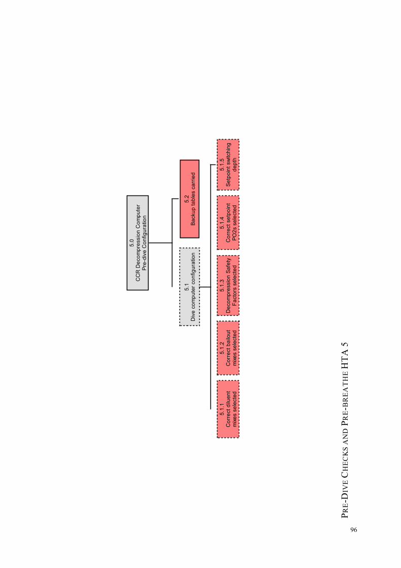
5.0
CC
R D
eco
mp
ressio
n C
om
pu
ter
Pre
-div
e C
on
fig
ura
tio
n
5.1
Div
e c
om
pu
ter
co
nfig
ura
tio
n
5.2
Ba
cku
p t
ab
les c
arr
ied
5.1
.1C
orr
ect
dilu
en
tm
ixe
s s
ele
cte
d
5.1
.4C
orr
ect
se
tpo
int
PO
2s s
ele
cte
d
5.1
.5S
etp
oin
t sw
itch
ing
de
pth
5.1
.3D
eco
mp
ressio
n S
afe
tyF
acto
rs s
ele
cte
d
5.1
.2C
orr
ect
ba
ilou
tm
ixe
s s
ele
cte
d
PRE
-DIV
E C
HEC
KS
AN
D P
RE-
BR
EAT
HE
HTA
5
96

6.0
Ba
ilou
t a
nd
Bu
oya
ncy C
he
cks
6.4
Off
-bo
ard
ba
ilou
t
6.4
.1O
ff-b
oa
rdb
ailo
ut
on
6.4
.4O
ff-b
oa
rd b
ailo
ut
reg
ula
tor
se
cu
red
6.1
On
-bo
ard
ba
ilou
t
6.4
.3O
ff-b
oa
rdb
ailo
ut
reg
ula
tor
fun
ctio
na
l
6.2
.3O
PR
V o
pe
n a
nd
loca
tab
le
6.2
Bre
ath
ing
lo
op
6
.3B
CD
an
d d
ry s
uit
6.4
.2O
ff-b
oa
rdS
PG
6.1
.1D
ilue
nt
ba
ilou
tre
gu
lato
r fu
nctio
na
l
6.1
.2O
2 b
ailo
ut
reg
ula
tor
fun
ctio
na
l
6.2
.2B
rea
thin
g lo
op
pu
lld
um
p lo
ca
tab
le
6.2
.4O
ve
r th
e s
ho
uld
er
co
un
terl
un
gs
faste
ne
d d
ow
n
6.2
.1M
ou
thp
iece
fu
llyo
pe
n
6.3
.3D
ry s
uit in
fla
tor
6.3
.1B
CD
in
fla
te
6.3
.2B
CD
de
fla
te
PRE
-DIV
E C
HEC
KS
AN
D P
RE-
BR
EAT
HE
HTA
6
97

7.0
Fin
al D
ry C
he
cks
(with B
ud
dy)
7.3
Co
nfig
ura
tio
n o
f C
CR
to D
ive P
lan
7.3
.1S
etp
oin
t 7
.3.2
Mix
es lo
ad
ed
7.3
.4B
ailo
ut
ca
rrie
d
7.3
.5C
om
pu
ters
wo
rn
7.2
O2 c
on
tro
l
7.2
.1E
lectr
on
ics o
n
7.2
.2A
larm
s a
nd
Wa
rnin
gs
7.2
.3P
O2 d
isp
laye
do
n h
an
dse
ts
7.1
Dilu
en
t a
nd O
2S
up
ply
7.1
.1S
lide
r va
lve
so
pe
n
7.1
.2P
ress d
ilue
nt
infla
tor
wh
ilew
atc
hin
g d
ilue
nt
SP
G
7.1
.4P
ress O
2 in
fla
tor
wh
ilew
atc
hin
g O
2 S
PG
7.3
.3B
ailo
ut
loa
de
d
7.1
.3P
ress/A
ctiva
teA
DV
7.1
.5B
rea
the o
n D
ilue
nt
in-b
oa
rd r
eg
ula
tor
Recom
mendation
of
buddy c
heck a
t th
ecom
ple
tion
of
the
pre
-bre
ath
e s
equence 7
.4C
on
firm
We
igh
tin
g
PRE
-DIV
E C
HEC
KS
AN
D P
RE-
BR
EAT
HE
HTA
7
98

APP
END
IX 4
: SH
ERPA
AN
ALY
SIS
FOR
TH
E PR
E-D
IVE
CH
ECK
S A
ND
PRE
-BRE
ATH
E
Task
Ste
p Er
ror
Mod
e Er
ror
Des
crip
tion
Con
sequ
ence
R
ecov
ery
P C
R
emed
ial S
trat
egy
CC
R e
lect
roni
cs m
onito
ring
1.1.
1Sw
itch
elec
troni
cs o
n
A8
Uni
t not
sw
itche
d on
N
o el
ectro
nics
con
trol,
PO2
not
disp
laye
d, n
o ox
ygen
add
ition
. If d
ived
switc
hed
off,
hypo
xia
and
deat
h w
ith n
oPO
2 w
arni
ngs.
7.2.
1 M
!!
Bud
dy c
heck
s w
ill e
stab
lish
that
the
unit
issw
itche
d on
prio
r to
ente
ring
wat
er.
Des
ign
-uni
t sw
itche
s on
han
dset
imm
ersi
on.
1.1.
2.1
Che
ckfo
r PO
2 ce
llw
arni
ngs
C1
O2
Cel
l war
ning
s ig
nore
d C
ompr
omis
ed P
O2 re
adin
gs, p
oten
tial
hypo
xia
or h
yper
oxia
. Dea
th.
7.2.
2 M
!!
Aud
ible
ala
rm fo
r no
dive
situ
atio
n. T
rain
ing
– fo
llow
any
han
dset
“N
o D
ive”
inst
ruct
ion
ifdi
spla
yed.
1.
1.2.
2 M
onito
rfo
r ala
rm b
eeps
/buz
zer
C1
Buz
zer /
Aud
ible
ala
rm te
stno
t lis
tene
d to
B
uzze
r, au
dibl
e al
arm
pot
entia
lly n
otfu
nctio
nal.
HU
D a
nd h
ands
ets
will
disp
lay
alar
ms.
7.2.
2 M
-
CC
R s
elf-d
iagn
ostic
s on
buz
zer a
nd a
larm
. Div
ertra
inin
g to
em
phas
ise
impo
rtanc
e of
regu
lar u
ser
mon
itorin
g of
PO
2 du
ring
the
dive
.1.
1.2.
3 C
heck
for l
ow b
atte
ryw
arni
ngs
C1
Low
bat
tery
war
ning
igno
red
Uni
t ele
ctro
nics
fail
unde
rwat
er.
Loss
of
PO
2 m
onito
ring
and
cont
rol.
Hyp
oxia
, dea
th
7.2.
2 M
!
Trai
ning
– fo
llow
man
ufac
ture
r’s
reco
mm
enda
tions
on b
atte
ry re
plac
emen
t. Tr
aini
ng –
follo
w a
nyha
ndse
t “N
o D
ive”
inst
ruct
ion
if di
spla
yed.
1.1.
2.4
Mon
itor
for e
lect
roni
cs
self-
test
failu
rew
arni
ng
C1
CC
R e
lect
roni
cs s
elf-t
est
failu
re w
arni
ng ig
nore
d U
nit e
lect
roni
cs fa
il un
derw
ater
. Lo
ss
of P
O2
mon
itorin
g an
d co
ntro
l.H
ypox
ia, d
eath
7.2.
2 M
!
Trai
ning
– fo
llow
man
ufac
ture
r’s
reco
mm
enda
tions
on s
ervi
cing
. Tra
inin
g –
follo
w a
ny h
ands
et “
No
Div
e” in
stru
ctio
n if
disp
laye
d.
1.1.
2.5
Che
ckfo
r O2
sole
noid
failu
re w
arni
ng
C1
CC
R u
nit s
elf-t
est o
fso
leno
id fa
ils a
nd u
ser
igno
res
the
war
ning
cap
tion
Aut
omat
ic a
dditi
on o
f O2 un
der s
yste
mco
ntro
l not
func
tiona
l. PO
2 w
ill d
rop
and
a lo
w P
O2 al
arm
gen
erat
ed.
4.5
M
-Tr
aini
ng –
follo
w a
ny h
ands
et “
No
Div
e”in
stru
ctio
n if
disp
laye
d. M
onito
r PO
2 re
gula
rly a
ndbe
aw
are
of so
leno
id a
ctio
n. A
lway
s co
nduc
t a p
re-
brea
the.
1.
1.2.
6 M
onito
rH
UD
C
1 H
UD
not
che
cked
dur
ing
unit
self
test
H
UD
may
hav
e co
mpl
etel
y or
par
tially
faile
d 4.
6 M
-
Trai
ning
-du
ring
the
pre-
brea
the
mon
itor a
ll fo
rms
of P
O2
disp
lays
(han
dset
(s) a
nd H
UD
)1.
1.3
Che
ck fo
rsc
rubb
er fi
lter
capt
ion
C1
Scru
bber
filte
r cap
tion
not
chec
ked
Scru
bber
mon
itorin
g m
ay n
ot b
efu
nctio
nal,
or s
crub
ber f
ilter
def
ectiv
e 4.
4 M
-
Trai
ning
-th
e pr
e-br
eath
e w
ill c
aptu
re so
me
scru
bber
erro
rs b
ut n
ot a
ll, e
mph
asis
e im
porta
nce
ofsc
rubb
er d
urat
ion
awar
enes
s an
d m
onito
ring.
1.1.
4 C
heck
HP
read
ings
C
1 H
P re
adin
gs (w
here
faci
lity
exis
ts) n
ot c
heck
ed
HP
mon
itorin
g m
ay n
ot b
e fu
nctio
nal
7.2.
2 M
-
Trai
ning
– e
nsur
e th
at H
P SP
Gs
are
mon
itore
din
term
itten
tly to
ver
ify h
ands
et re
adou
ts fo
r O2
and
Dilu
ent p
ress
ures
.1.
2.1
Ente
r FO
2of
O2
cylin
der
A4
O2
supp
ly F
O2
ente
red
inco
rrect
ly
CC
R U
nit s
peci
fic -
self
chec
ks m
ayre
ject
this
and
resu
lt in
'No
Div
e' if
valu
e is
out
of r
ange
. Cal
ibra
tion
mig
htbe
affe
cted
.
CC
R s
elf
mon
itorin
g L
-Tr
aini
ng -
Emph
asis
e th
e im
porta
nce
of c
orre
ct g
asan
alys
is a
nd la
belli
ng, a
nd im
plic
atio
ns o
f not
doin
g th
is p
rope
rly. C
onsi
der b
uild
ing
gas
anal
ysis
into
CC
R u
nit s
elf-c
heck
.
99

1.2.
2 En
ter
atm
osph
eric
pres
sure
A8
Atm
osph
eric
Pre
ssur
een
tere
d in
corre
ctly
C
CR
Uni
t spe
cific
– s
ome
units
will
dete
ct p
ress
ure
and
appl
y. C
alib
ratio
nco
uld
be af
fect
ed i
n ot
hers
.
CC
R s
elf
mon
itorin
g L
! Tr
aini
ng –
em
phas
ise
calib
ratio
n pr
oced
ures
intra
inin
g.
1.2.
3 O
2C
alib
ratio
n A
4 O
2 ca
libra
tion
inco
rrect
C
CR
Uni
t spe
cific
– s
elf c
heck
s m
ayre
ject
inco
rrect
cal
ibra
tion
and
resu
lt in
‘No
Div
e’, a
ltern
ativ
ely
PO2
read
ings
w
ill b
e in
corre
ct
CC
R s
elf
mon
itorin
g L
! Tr
aini
ng –
teac
h w
hen
and
unde
r whi
ch c
ondi
tions
calib
ratio
n sh
ould
be
perfo
rmed
.
Bre
athi
ng L
oop
Che
cks
2.1
Che
ckm
ushr
oom
valv
es
C1
Mus
hroo
m v
alve
s no
tvi
sual
ly in
spec
ted
Hig
h C
O2
exha
lant
may
min
gle
with
inha
lant
cau
sing
hyp
erca
pnia
, Bai
lout
. 4.
4 H
!!
Perfo
rm 5
min
ute
pre-
brea
the.
Em
phas
ise
impo
rtanc
e in
trai
ning
2.2
Che
ckm
outh
piec
ein
tegr
ity
C1
Mou
thpi
ece
not v
isua
llyin
spec
ted
Wat
er m
ay e
nter
mou
thpi
ece
and
brea
thin
g lo
op, p
oten
tial l
oop
flood
.B
ailo
ut
Non
e M
-
Trai
ning
– s
ubse
quen
t pre
ssur
e te
sts
will
not
det
ect
this
so
visu
al in
spec
tion
esse
ntia
l.
2.3
Che
ckin
tegr
ity o
fm
outh
piec
eas
sem
bly
and
hose
fitti
ngs
C1
Mou
thpi
ece
asse
mbl
y an
dho
se fi
tting
s no
t che
cked
W
ater
may
ent
er th
e lo
op, p
oten
tial
loop
floo
d. B
ailo
ut
2.4
and
2.5
M
-Pe
rform
neg
ativ
e an
d po
sitiv
e pr
essu
re te
st.
Trai
ning
to e
mph
asis
e co
rrect
ass
embl
y of
rebr
eath
er u
nit.
2.4.
Con
duct
brea
thin
g lo
opne
gativ
epr
essu
re te
st
C1
Bre
athi
ng lo
op le
akne
gativ
e pr
essu
re te
st n
otpe
rform
ed
Pote
ntia
l bre
athi
ng lo
op le
ak. E
xces
sive
gas
cons
umpt
ion,
wat
er in
sys
tem
,in
crea
sed
wor
k of
bre
athi
ng. P
ossi
ble
TL
F. B
ailo
ut.
Bub
ble
Che
ck
H
-Pe
rform
bud
dy b
ubbl
e ch
eck.
You
r lea
k m
ay b
ein
dica
ted
by b
ubbl
es u
nder
wat
er w
hich
may
be
spot
ted
by y
our b
uddy
.
2.4.
4 W
ait
A1
Neg
ativ
e lo
op te
st is
not
perfo
rmed
for l
ong
enou
gh
Leak
may
rem
ain
unde
tect
ed
Bub
ble
Che
ck
M
-Fo
llow
man
ufac
ture
r's o
r tra
inin
g ag
ency
gui
danc
eon
how
long
the
nega
tive
loop
test
sho
uld
bepe
rform
ed fo
r (gu
idan
ce v
arie
s).
2.4.
5 M
onito
rfo
r lea
ks
C2
Leak
test
per
form
ed b
ut le
akno
t det
ecte
d.
Smal
l bre
athi
ng lo
op le
aks
may
not
be
spot
ted.
Bub
ble
chec
k m
ay in
dica
teso
urce
of p
robl
em.
Bub
ble
Che
ck
M
-Pe
rform
bud
dy b
ubbl
e ch
eck.
You
r lea
k m
ay b
ein
dica
ted
by b
ubbl
es u
nder
wat
er w
hich
may
be
spot
ted
by y
our b
uddy
. Fol
low
man
ufac
ture
rs a
ndtra
inin
g ag
ency
gui
danc
e re
latin
g to
CC
R le
aks.
2.5
Con
duct
brea
thin
g lo
oppo
sitiv
epr
essu
re te
st
C1
Bre
athi
ng lo
op le
ak p
ositi
vepr
essu
re te
st n
ot p
erfo
rmed
Po
tent
ial b
reat
hing
loop
leak
. Exc
essi
vega
s co
nsum
ptio
n, w
ater
in s
yste
m,
incr
ease
d w
ork
of b
reat
hing
. Pos
sibl
eT
LF.
Bai
lout
.
Bub
ble
Che
ck
H
-Pe
rform
bud
dy b
ubbl
e ch
eck.
You
r lea
k m
ay b
ein
dica
ted
by b
ubbl
es u
nder
wat
er w
hich
may
be
spot
ted
by y
our b
uddy
.
2.5.
4 W
ait
A1
Posi
tive
pres
sure
loop
test
is n
ot p
erfo
rmed
for l
ong
enou
gh
Leak
may
rem
ain
unde
tect
ed. T
hepo
sitiv
e lo
op te
st is
a m
ore
dem
andi
ngte
st th
an th
e ne
gativ
e lo
op te
st s
o w
illpo
tent
ially
det
ect s
mal
ler l
eaks
.
Bub
ble
Che
ck
H
-Fo
llow
man
ufac
ture
r's o
r tra
inin
g ag
ency
gui
danc
eon
how
long
the
posi
tive
loop
test
sho
uld
be
perfo
rmed
for (
guid
ance
var
ies)
.
100

2.5.
5 M
onito
rfo
r lea
ks
C2
Leak
test
per
form
ed b
ut le
akno
t det
ecte
d.
Smal
l bre
athi
ng lo
op le
aks
may
not
be
spot
ted.
Bub
ble
chec
k m
ay in
dica
teso
urce
of p
robl
em.
Bub
ble
Che
ck
M
-Pe
rform
bud
dy b
ubbl
e ch
eck.
You
r lea
k m
ay b
ein
dica
ted
by b
ubbl
es u
nder
wat
er w
hich
may
be
spot
ted
by y
our b
uddy
. Fol
low
man
ufac
ture
rs a
ndtra
inin
g ag
ency
gui
danc
e re
latin
g to
CC
R le
aks.
O2
and
Dilu
ent S
uppl
y Le
ak C
heck
s 3.
1.5.
1M
onit
orO
2SPG
for
drop
inpr
essu
re
C1
O2
supp
ly le
ak c
heck
not
perfo
rmed
O
2 fir
st s
tage
may
not
be
conn
ecte
d to
O2
Supp
ly. O
2 un
avai
labl
e. P
ossi
ble
loop
floo
ding
. PO
2 al
arm
may
trig
ger i
fel
ectro
nics
are
still
func
tiona
l. B
ailo
ut.
7.1.
4 M
!
Use
a c
heck
-list
to a
id a
ssem
bly,
and
ass
embl
e th
eC
CR
in a
situ
atio
n w
here
one
is n
ot u
nder
tim
epr
essu
re.
O2
first
sta
ge m
ay n
ot b
e fu
llyco
nnec
ted
to O
2 su
pply
. O2
leak
ing.
Poss
ible
floo
ding
of t
he lo
op. P
O2
alar
m m
ay tr
igge
r if e
lect
roni
cs a
re s
till
func
tiona
l. B
ailo
ut.
Bub
ble
chec
k M
!
Mon
itor h
ands
ets
and
O2
SPG
(Tr
aini
ng)
O2
hose
s m
ay n
ot b
e co
nnec
ted
to fi
rst
stag
e pr
oper
ly, o
r may
be
leak
ing.
O2
SPG
cou
ld b
e le
akin
g. O
2 su
pply
may
beco
me
exha
uste
d.
Bub
ble
chec
k M
!
Mon
itor O
2 SP
G (
Trai
ning
)
3.1.
5.2
Mon
itor
Dilu
ent S
PG fo
rpr
essu
re d
rop
C1
Dilu
ent s
uppl
y le
ak c
heck
not p
erfo
rmed
D
iluen
t firs
t sta
ge m
ay n
ot b
e co
nnec
ted
to D
iluen
t sup
ply.
Dilu
ent u
nava
ilabl
e.Po
ssib
le lo
op fl
oodi
ng, d
iluen
t add
ition
to lo
op v
olum
e an
d bu
oyan
cy n
otav
aila
ble.
In-b
oard
bai
lout
not
ava
ilabl
e
7.1.
2 M
-
Use
a c
heck
-list
to a
id a
ssem
bly,
and
ass
embl
e th
eC
CR
in a
situ
atio
n w
here
one
is n
ot u
nder
tim
epr
essu
re.
Dilu
ent f
irst s
tage
may
not
be
fully
conn
ecte
d to
Dilu
ent s
uppl
y. D
iluen
tle
akin
g. P
ossi
ble
flood
ing
of th
e lo
op.
Bai
lout
.
Bub
ble
chec
k M
-
Mon
itor D
iluen
t SPG
(Tr
aini
ng)
Dilu
ent h
oses
may
not
be
conn
ecte
d to
first
sta
ge p
rope
rly, o
r may
be
leak
ing.
Dilu
ent S
PG c
ould
be
leak
ing.
Dilu
ent
supp
ly m
ay b
ecom
e ex
haus
ted.
Bub
ble
chec
k M
-
Mon
itor D
iluen
t SPG
(Tr
aini
ng)
101

O2
and
Dilu
ent S
uppl
y C
onne
ctio
n C
heck
s3.
2.2
Pres
s O
2m
anua
l inf
lato
r A
8 O
2 m
anua
l inf
lato
r not
pres
sed
O2
man
ual s
uppl
y ch
eck
cann
ot b
epe
rform
ed
4.6
7.1.
4 M
-
Ensu
re fi
nal d
ry c
heck
s w
ith a
bud
dy a
re p
erfo
rmed
.
3.2.
3 M
onito
rO
2 SP
G fo
rpr
essu
re ri
se
C1
O2
supp
ly c
heck
not
perfo
rmed
(by
pres
sing
O2
infla
tor w
hile
wat
chin
g O
2 SP
G)
O2
LP
supp
ly m
ay n
ot b
e ph
ysic
ally
conn
ecte
d to
O2
infla
tor.
Man
ual O
2 in
flato
rdo
es n
ot a
dd O
2 in
to th
e br
eath
ing
loop
4.6
7.1.
4 M
-
Ensu
re fi
nal d
ry c
heck
s w
ith a
bud
dy a
re p
erfo
rmed
.
3.2.
3 C
1 O
2 SP
G n
ot w
atch
eddu
ring
O2
supp
lych
eck
O2
supp
ly m
ay b
e al
mos
t em
pty.
Low
PO
2 al
arm
whe
n O
2 su
pply
exh
aust
ed,
if al
arm
igno
red
hypo
xia
and
deat
h. B
ailo
ut.
7.1.
4 an
dB
ubbl
ech
eck
M
! Fi
nal S
PG c
heck
prio
r to
desc
ent.
Che
ck S
PGs
durin
g th
e di
ve.
3.2.
3 C
1 O
2 SP
G n
ot w
atch
eddu
ring
O2
supp
lych
eck
(i.e
. nee
dle
dips
/bou
nces
)
O2
valv
e m
ay b
e on
ly fr
actio
nally
ope
n.Po
tent
ial f
or v
alve
to b
e cl
osed
inad
verte
ntly
on d
ive.
Low
O2
alar
m w
hich
, if i
gnor
edle
ads
to h
ypox
ia a
nd d
eath
.
7.1.
4 L
!! Em
phas
ise
pote
ntia
l iss
ue d
urin
g tra
inin
g,es
peci
ally
sig
nific
ance
of i
ssue
on
asce
nt (s
olen
oid
may
not
be
able
to a
dd s
uffic
ient
O2
into
bre
athi
nglo
op to
mai
ntai
n PO
2 w
ithin
bre
atha
ble
limits
)3.
3.2
Ope
ndi
luen
t slid
erva
lve
if fit
ted
A8
Dilu
ent s
lider
(flo
wst
op) v
alve
not
ope
ned
[if s
lider
val
ve fi
tted
toA
DV
sup
ply]
.
Dilu
ent s
uppl
y to
AD
V in
hibi
ted
(bot
hau
tom
atic
and
man
ual m
ode
of o
pera
tion)
.U
ser w
ill h
ave
to p
ress
dilu
ent m
anua
lin
flato
r to
add
dilu
ent i
nto
brea
thin
g lo
op.
3.3.
37.
1.1
M
-T
his
erro
r will
be
trapp
ed b
y th
e A
DV
val
ve te
st.
Rec
heck
all
slid
er (f
low
sto
p) v
alve
s fitt
ed p
rior t
oen
terin
g w
ater
.D
esig
n -c
onsi
der f
ittin
g sl
ider
val
ves
that
hav
e a
visu
al in
dica
tion
of v
alve
sta
tus,
and
val
ves
that
cann
ot b
e cl
osed
acc
iden
tally
.3.
3.3
Pres
s/A
ctiv
ate
AD
V v
alve
A8/
C1
AD
V v
alve
not
pre
ssed
(or a
ctiv
ated
by
inha
latio
n) to
con
firm
func
tiona
l AD
V.
AD
V m
ay b
e no
n-fu
nctio
nal,
or d
iluen
tsu
pply
to A
DV
may
be
inhi
bite
d (fl
ow s
top
valv
e cl
osed
or d
iluen
t sup
ply
turn
ed o
ff)
7.1.
3 M
-
Emph
asis
e im
porta
nce
of m
aint
enan
ce o
f bre
athi
nglo
op v
olum
e on
des
cent
and
how
AD
V a
nd m
anua
ldi
luen
t inf
lato
r can
be
oper
ated
to a
chie
ve th
is.
Con
side
r inc
orpo
ratin
g C
CR
des
cent
s w
ithou
tus
ing
the
AD
V in
to tr
aini
ng.
3.3.
4 Pr
ess
dilu
ent m
anua
lin
flato
r
A8
Dilu
ent m
anua
l inf
lato
rno
t pre
ssed
D
iluen
t man
ual s
uppl
y ch
eck
cann
ot b
e pe
rform
ed
7.1.
2 M
-
Ensu
re fi
nal d
ry c
heck
s w
ith a
bud
dy a
re p
erfo
rmed
.
3.3.
5 M
onito
rD
iluen
t SPG
C
1 D
iluen
t SPG
not
wat
ched
dur
ing
Dilu
ent
supp
ly c
heck
Dilu
ent s
uppl
y m
ay b
e al
mos
t em
pty.
Pote
ntia
lly c
ritic
al o
n de
scen
t (lo
ss o
f loo
pvo
lum
e an
d in
abili
ty to
est
ablis
h po
sitiv
ebu
oyan
cy)
7.12
and
Bub
ble
chec
k
M
! En
sure
fina
l dry
che
cks
with
a b
uddy
are
per
form
ed.
Car
ry o
ut fi
nal d
iluen
t SPG
che
ck p
rior t
o de
scen
t.
3.3.
5 C
1 D
iluen
t SPG
not
wat
ched
dur
ing
Dilu
ent
supp
ly c
heck
(i.e
.ne
edle
dip
s/bo
unce
s)
Dilu
ent v
alve
may
be
only
frac
tiona
lly o
pen.
Pote
ntia
l to
be c
lose
d in
adve
rtent
ly o
n di
ve.
Pote
ntia
lly c
ritic
al o
n de
scen
t – A
DV
or
dilu
ent i
nfla
tor m
ay n
ot b
e ab
le to
add
suffi
cien
t dilu
ent t
o m
aint
ain
loop
vol
ume.
7.1.
2 L
! Em
phas
ise
pote
ntia
l iss
ue d
urin
g tra
inin
g.
102

Pre-
brea
the
on th
e U
nit
4.1
Put o
n m
ask
A8
Mas
k no
t wor
n (o
r nos
eno
t blo
cked
) dur
ing
pre-
brea
the
Div
er m
ay s
ubco
nsci
ousl
y st
art t
obr
eath
e th
roug
h no
se to
com
pens
ate f
orel
evat
ed C
O2
in th
e br
eath
ing
loop
–
pre-
brea
the
pote
ntia
lly n
ot e
ffect
ive.
Non
e H
!!
Trai
ning
-en
cour
age
budd
y pa
irs p
re-b
reat
heto
geth
er. E
mph
asis
on
impo
rtanc
e of
blo
ckin
g no
sedu
ring
pre-
brea
the
4.4.
2 C
heck
PO
2 re
adin
gs fo
rst
abili
ty, r
eact
ion
time
and
agre
emen
t
C1
Cel
ls d
ispl
ays
on h
ands
etno
t mon
itore
d du
ring
exha
latio
n
Slow
cel
ls, c
ells
with
uns
tabl
e re
adin
gsan
d ce
lls d
isre
gard
ed w
ill n
ot b
e pi
cked
up. P
oten
tial c
ell i
ssue
s (s
uch
asm
oist
ure
on a
cel
l not
pic
ked
up)
7.2.
3 M
-
Trai
ning
– c
ell r
eact
ion
spee
d, s
tabi
lity
of ce
llva
lues
and
cel
l rea
ding
s be
ing
clos
e to
eac
h ot
her
4.4.
3 Li
sten
for
sole
noid
firin
g C
1 So
leno
id n
ot li
sten
ed fo
ror
sol
enoi
d no
t hea
rd
If th
e so
leno
id d
oes
not o
pera
te th
enPO
2 w
ill n
ot b
e m
aint
aine
d in
the
pre-
brea
the
and
a lo
w P
O2
alar
m w
ill b
ege
nera
ted.
If th
e C
CR
ele
ctro
nics
are
not t
urne
d on
then
sym
ptom
s of
hypo
xia
will
be
appa
rent
with
in 5
min
utes
.
4.6
M
-Tr
aini
ng -
enco
urag
e C
CR
div
ers
to li
sten
for t
heso
leno
id a
nd w
atch
PO
2 le
vels
dur
ing
the
pre-
brea
the.
Des
ign
– co
nsid
er a
uni
t tha
t tur
ns it
self
onau
tom
atic
ally
if P
O2
drop
s in
the
loop
.D
esig
n –
ensu
re so
leno
id o
pera
tion
is a
udib
le to
the
dive
r.
4.4.
4 M
onito
r PO
2 C
1 PO
2 no
t mon
itore
d in
the
pre-
brea
the
PO2
leve
ls m
ay n
ot b
e be
ing
mai
ntai
ned
/ inc
reas
ed to
the
chos
en lo
w s
et p
oint
. 4.
6 M
-
As
abov
e.
4.4.
6 Li
sten
for
AD
V o
pera
ting
C1
AD
V n
ot li
sten
ed fo
r If
the
AD
V is
not
func
tiona
l the
n on
initi
al in
hala
tion
on th
e pr
e-br
eath
ebr
eath
ing
loop
vol
ume
will
not
be
adde
d, s
o br
eath
ing
in w
ill b
edi
fficu
lt/im
poss
ible
if th
e br
eath
ing
loop
is p
rope
rly s
eale
d.
Can
not
proc
eed.
L
-D
iagn
ose
prob
lem
, unl
ikel
y to
occ
ur if
loop
nega
tive
pres
sure
test
(2.4
) and
AD
V s
uppl
y te
st(3
.3.3
) hav
e be
en p
erfo
rmed
cor
rect
ly.
4.5
Pre-
brea
the f
or5
min
utes
A
1 Pr
e-br
eath
e is
less
than
5m
inut
es
Shor
ter p
re-b
reat
hes
are
less
effe
ctiv
e at
pick
ing
up p
oten
tial C
O2
issu
es w
hich
are
man
ifest
ed a
t the
sta
rt of
the
dive
.
Non
e M
!!
Use
tim
ing
devi
ce o
r pre
-bre
athe
bui
lt in
to C
CR
syst
em c
heck
s. T
rain
ing
-enc
oura
ge b
uddy
pai
rspr
e-br
eath
e to
geth
er. I
t is
impo
rtant
to e
mph
asis
eth
at a
pre
-bre
athe
will
not
pic
k up
all
scru
bber
rela
ted
issu
es (s
uch
as o
ld s
crub
ber m
ater
ial w
hich
will
be
push
ed b
eyon
d its
abi
lity
to a
bsor
b C
O2
beca
use
of p
revi
ous
dive
s), s
o sc
rubb
er p
acki
ng a
ndaw
aren
ess
of sc
rubb
er d
urat
ions
are
als
o cr
itica
lsu
rviv
al s
kills
.4.
6 M
onito
r et
poin
t mai
nten
ance
C
1 PO
2 le
vels
mai
ntai
ned
atse
tpoi
nt n
ot c
onfir
med
at
end
of p
re-b
reat
he
CC
R u
nit P
O2
man
agem
ent m
ay n
otfu
nctio
n pr
oper
ly u
nder
wat
er.
Non
e M
!
Con
side
r cro
ss c
heck
ing
with
bud
dy a
t the
end
of
the
brea
the
sequ
ence
.
4.7
Com
pare
prim
ary
and
back
upha
ndse
t rea
ding
s
C1
Prim
ary
and
Bac
kup
hand
sets
not
refe
renc
edag
ains
t eac
h ot
her
Han
dset
s no
t in
agre
emen
t, on
e ha
ndse
tm
ay b
e di
spla
ying
an
erro
r. Se
cond
ary
hand
set m
ay h
ave
prom
oted
to p
rimar
y.
7.2.
3 M
-
Due
to re
dund
ancy
in s
yste
ms
desi
gn u
nlik
ely
to b
ecr
itica
l. C
ross
che
ck h
ands
ets
with
bud
dy p
rior t
odi
ve.
103

Pre-
Div
e C
onfig
urat
ion
of C
CR
and
Ext
erna
l Dec
ompr
essi
on C
ompu
ters
5.1.
1 C
heck
corre
ct d
iluen
tm
ix s
elec
ted
A8/
A9/
C1
Cor
rect
dilu
ent m
ix/m
ixes
not
conf
igur
ed to
refle
ct d
ive
plan
In
corre
ct d
ecom
pres
sion
info
rmat
ion.
Pot
entia
lly C
NS
toxi
city
or D
CS
7.3.
2 M
!
Mak
e a
writ
ten
plan
of t
he d
ive
deta
ils a
nd g
asco
nfig
urat
ion
prio
r to
getti
ng o
n th
e bo
at. C
ross
chec
k de
tails
with
bud
dy.
5.1.
2 C
heck
bailo
ut m
ix(s
)m
atch
div
epl
an
A8/
A9/
C1
Cor
rect
bai
lout
mix
/mix
es n
otco
nfig
ured
to re
flect
div
e pl
an
Inco
rrect
dec
ompr
essi
onin
form
atio
n. P
oten
tially
CN
Sto
xici
ty o
r DC
S
7.3.
3 M
!
Mak
e a
writ
ten
plan
of t
he d
ive
deta
ils a
nd g
asco
nfig
urat
ion
prio
r to
getti
ng o
n th
e bo
at. C
ross
chec
k de
tails
with
bud
dy.
5.1.
3 C
heck
deco
mpr
essi
onsa
fety
fact
ors
are
appr
opria
te
A8/
A9/
C1
Dec
ompr
essi
on s
afet
y fa
ctor
s /
grad
ient
fact
ors
not a
ppro
pria
tely
cons
erva
tive
Dec
ompr
essi
on s
ched
ule
may
not
be a
ppro
pria
tely
con
serv
ativ
e fo
rdi
ve c
ondi
tions
and
div
er p
erso
nal
heal
th fa
ctor
s. D
CS.
Non
e M
-
Trai
ning
and
edu
catio
n –
dive
con
serv
ativ
ely
and
fact
or in
app
ropr
iate
safe
ty m
argi
ns to
deco
mpr
essi
on c
alcu
latio
ns.
5.1.
4 C
heck
Hig
h an
d Lo
wse
t poi
nts
refle
ct d
ive
plan
A8/
A9/
C1
Hig
h an
d Lo
w s
et p
oint
s no
tco
nfig
ured
to re
flect
div
e pl
an
Dec
ompr
essi
on in
form
atio
n w
ill b
ein
corre
ct. P
oten
tially
CN
S to
xici
tyor
DC
S.
7.3.
1 M
!
Mak
e a
writ
ten
plan
of t
he d
ive
deta
ils a
nd g
asco
nfig
urat
ion
prio
r to
getti
ng o
n th
e bo
at. C
ross
chec
k de
tails
with
bud
dy.
5.1.
5 C
heck
set p
oint
switc
hing
dept
h m
atch
esdi
ve p
lan
A8/
A9/
C1
Setp
oint
sw
itchi
ng d
epth
not
se
lect
ed to
refle
ct th
e pl
an
Dec
ompr
essi
on in
form
atio
n w
ill b
ein
corre
ct, p
oten
tial D
CS.
N
one
M
-Fo
llow
the
writ
ten
plan
mad
e in
the
dive
pla
nnin
gst
age.
5.2
Che
ckba
ckup
tabl
espr
epar
ed
A8
Bac
kup
tabl
es n
ot p
repa
red
Dec
ompr
essi
on in
form
atio
n no
tav
aila
ble
if di
ve in
stru
men
tatio
nfa
ils. P
oten
tial D
CS.
Non
e M
!
Ensu
re th
at tw
o in
depe
nden
t set
s of
Dec
ompr
essi
onin
form
atio
n ar
e av
aila
ble,
suc
h as
CC
Rde
com
pres
sion
ele
ctro
nics
and
eith
er o
ther
deco
mpr
essi
on c
ompu
ter o
r dec
ompr
essi
on ta
bles
.B
ailo
ut a
nd B
uoya
ncy
Che
cks
6.1.
1 C
heck
inbo
ard
dilu
ent
bailo
utre
gula
tor
func
tiona
l
C1
Failu
re to
che
ck th
at in
-boa
rddi
luen
t bai
lout
regu
lato
r is
func
tiona
l
Seco
nd s
tage
may
be
inop
erab
le,
pote
ntia
l to
caus
e di
ver p
anic
and
drow
ning
in a
n em
erge
ncy
situ
atio
nre
quiri
ng b
ailo
ut.
Alte
rnat
ive
bailo
utre
gula
tor
M
! C
heck
the
func
tioni
ng o
f the
firs
t bai
lout
regu
lato
rw
ith c
are,
esp
ecia
lly if
a fl
ow s
top
valv
e is
fitte
d(a
lso
appl
ies
to in
built
BO
Vs)
. Fol
low
man
ufac
ture
r’s
guid
ance
on
regu
lato
r ser
vici
ng.
6.1.
2 C
heck
in-b
oard
O2
bailo
utre
gula
tor
func
tiona
l
C1
[opt
iona
l ite
m]
Failu
re to
che
ck th
at in
-boa
rd O
2ba
ilout
regu
lato
r is f
unct
iona
l
Seco
nd s
tage
may
be
inop
erab
le,
pote
ntia
l to
caus
e di
ver p
anic
,dr
owni
ng in
a b
ailo
ut s
cena
rio.
How
ever
this
is n
ot li
kely
to b
e th
ech
osen
bai
lout
regu
lato
r due
dep
thlim
its o
f pur
e O
2.
Alte
rnat
ive
bailo
utre
gula
tor
(unl
ikel
y)
M
! B
ailo
ut to
Oxy
gen
only
app
lies
shal
low
er th
an 6
msw
.
104

6.2.
1 C
heck
mou
thpi
ece
C1
Mou
thpi
ece
not c
heck
ed
Parti
ally
ope
n m
outh
piec
es c
an le
akun
derw
ater
. Dilu
ent f
lush
es, l
oop
flood
reco
very
dril
ls, e
xces
sive
gas
cons
umpt
ion.
Non
e M
-
Con
side
r sof
twar
e-dr
iven
che
ck-li
st o
r writ
ten
/la
min
ated
che
ck-li
st. C
onsi
der t
he p
repa
ratio
n an
dfo
llow
ing
of a
che
ck-li
st a
s pa
rt of
the
CC
R u
nit
train
ing.
6.
2.2
Loca
tebr
eath
ing
loop
pull
dum
p (if
fitte
d)
C1
Bre
athi
ng lo
op p
ull-d
ump
not
chec
ked
to b
e fre
e of
obs
truct
ion.
The
bre
athi
ng lo
op p
ull d
ump
may
be
trapp
ed u
nder
oth
ereq
uipm
ent a
nd p
erpe
tual
lyve
ntin
g.
On
desc
ent t
his
coul
d ca
use
gas
tove
nt fr
om b
reat
hing
loop
, and
floo
dth
e br
eath
ing
loop
. Bai
lout
and
buoy
ancy
sta
bilis
atio
n re
quire
d.
Non
e M
!
Con
side
r col
our c
odin
g co
rd a
nd p
ull d
ump
so th
ata
trapp
ed p
ull d
ump
is m
ore
visi
ble.
Con
side
rbu
ildin
g th
e ch
eck
proc
edur
e in
to p
re-d
ive
chec
k w
ith b
uddy
.
C1
Bre
athi
ng lo
op p
ull-d
ump
not
loca
ted
and
conf
irmed
to b
e fre
eof
obs
truct
ion
to m
ovem
ent.
In a
fast
asc
ent s
ituat
ion
not b
eing
able
to re
ach
the
pull
dum
p to
ven
tex
pand
ing
brea
thin
g lo
op v
olum
em
ight
lead
to a
n irr
ecov
erab
ly fa
stas
cent
. Pot
entia
l om
itted
DC
S an
dlu
ng e
xpan
sion
issu
es.
Non
e M
!
Con
side
r col
our c
odin
g co
rd a
nd p
ull d
ump
so th
ata
trapp
ed p
ull d
ump
is m
ore
visi
ble.
Con
side
rbu
ildin
g pr
oced
ure
into
pre
-div
e ch
eck
with
bud
dy.
6.2.
3 C
heck
OPR
V o
pen
and
loca
tabl
e
C1
OPR
V n
ot c
heck
ed to
be
oper
able
O
PRV
may
be
dam
aged
, or s
tuck
eith
er c
lose
d or
ope
n. A
n O
PRV
stuc
k cl
osed
mea
ns th
at b
reat
hing
loop
vol
ume
expa
nsio
n ne
eds
to b
em
anag
ed m
anua
lly. P
oten
tial a
scen
tis
sues
and
pot
entia
l hig
her r
isk
oflu
ng e
xpan
sion
inju
ries.
OPR
Vst
uck
open
mea
ns th
at lo
op in
tegr
itypr
essu
re te
sts
cann
ot b
e pe
rform
ed.
Non
e M
-
Follo
w m
aint
enan
ce in
stru
ctio
ns, c
onsi
der a
ddin
gth
is it
em in
to a
pre
-div
e ch
eck-
list..
C1
OPR
V n
ot c
heck
ed to
be
open
R
eally
onl
y an
issu
e on
asc
ent,
ther
ear
e se
vera
l des
cent
che
cks
that
shou
ld tr
ap th
is e
rror.
On
desc
ent
OPR
Vch
eck
L -
Trai
ning
– c
onsi
der a
ddin
g ra
pid
asce
ntm
anag
emen
t the
ory
into
trai
ning
cou
rses
and
actio
ns to
per
form
in s
ituat
ions
with
jam
med
infla
tors
and
/or v
entin
g no
t occ
urrin
g.
6.2.
4 C
heck
over
-sho
ulde
rco
unte
r lun
gsad
just
edco
rrect
ly
C1
[opt
iona
l ite
m]
Ove
r the
sho
ulde
r cou
nter
lung
sno
t che
cked
to b
e ad
just
edco
rrect
ly (i
f uni
t has
OT
SCL)
Wor
k of
bre
athi
ng n
ot o
ptim
al
Bub
ble
chec
k M
-
The
bub
ble
chec
k sh
ould
allo
w th
is p
oten
tial i
ssue
to b
e co
rrect
ed
6.3.
1 C
heck
BC
D in
flatio
n C
1 B
CD
infla
tion
not t
este
d B
uoya
ncy
cont
rol i
ssue
s, s
erio
us if
no a
ltern
ativ
e m
eans
of b
uoya
ncy
such
as
a dr
y su
it or
dua
l bla
dder
BC
can
be
used
to e
stab
lish
posi
tive
buoy
ancy
. Cou
ld u
ltim
atel
y le
ad to
D
row
ning
, Dea
th.
Plug
bailo
utsu
pply
into
BC
D
M
! C
arry
bai
lout
sup
ply
with
com
patib
le h
ose
to p
lug
into
BC
D (c
onsi
der i
nter
oper
abili
ty w
ith d
ry s
uit a
sw
ell).
Con
side
r add
ing
this
item
into
a p
re-d
ive
chec
k-lis
t.
105

6.3.
2 C
heck
BC
D d
efla
tion
C1
BC
D d
efla
tion
not t
este
d B
CD
def
latio
n w
ill b
e te
sted
on
desc
ent s
o un
likel
y to
be
an is
sue
ifth
e di
ve is
sta
rted
with
dilu
ent i
n th
eB
CD
.
Non
e M
!
Trai
ning
– c
onsi
der a
ddin
g ra
pid
asce
ntm
anag
emen
t the
ory
into
trai
ning
cou
rses
and
actio
ns to
per
form
in s
ituat
ions
with
jam
med
infla
tors
and
/or v
entin
g no
t occ
urrin
g.6.
3.3
Che
ckdr
y su
itin
flatio
n
C1
Dry
sui
t inf
latio
n no
t tes
ted
Buo
yanc
y co
ntro
l iss
ues.
Sui
tsq
ueez
e -d
iver
dis
com
fort,
rest
ricte
dm
ovem
ent,
com
prom
ised
ther
mal
prot
ectio
n
Non
e M
-
Plug
bai
lout
BC
D s
uppl
y in
to d
ry s
uit
6.4.
1 C
heck
off-b
oard
bailo
ut v
alve
open
C1
Off-
boar
d ba
ilout
val
ve c
lose
d B
ailo
ut g
as n
ot a
vaila
ble
whe
nde
sper
atel
y re
quire
d. P
ossi
ble
dive
rpa
nic
and
drow
ning
6.5.
3 M
B !!
Emph
asis
e im
porta
nce
of b
ailo
ut a
nd b
ailo
ut c
heck
spr
ior t
o st
artin
g th
e di
ve.
6.4.
2 C
heck
off-b
oard
bailo
ut S
PGfu
nctio
nal
C1
Off-
boar
d ba
ilout
SPG
not
chec
ked
Off-
boar
d ba
ilout
con
tent
s m
ay b
eal
mos
t em
pty.
In a
n a
bailo
utsi
tuat
ion
pote
ntia
lly D
CS
ordr
owni
ng.
7.1.
5 M
B !!
Emph
asis
e im
porta
nce
of b
ailo
ut a
nd b
ailo
ut c
heck
spr
ior t
o st
artin
g th
e di
ve.
6.4.
3 C
heck
off-b
oard
bailo
utre
gula
tor
func
tiona
l
C1
Off-
boar
d ba
ilout
not
bre
athe
dfro
m
Off-
boar
d ba
ilout
may
be
empt
y, n
otco
nnec
ted.
Bai
lout
not
ava
ilabl
e,po
tent
ial d
iver
pan
ic a
nd d
row
ning
.
7.1.
5 M
B !!
Emph
asis
e im
porta
nce
of b
ailo
ut a
nd b
ailo
ut c
heck
spr
ior t
o st
artin
g th
e di
ve.
C1
Off-
boar
d ba
ilout
not
bre
athe
dfro
m
Off-
boar
d ba
ilout
regu
lato
r not
func
tiona
l. B
ailo
ut n
ot a
vaila
ble,
pote
ntia
l div
er p
anic
and
dro
wni
ng.
Non
e M
B !!
Emph
asis
e im
porta
nce
of b
ailo
ut a
nd b
ailo
ut c
heck
spr
ior t
o st
artin
g th
e di
ve.
C1
Off-
boar
d ba
ilout
not
bre
athe
dfro
m
Bai
lout
gas
may
not
hav
e su
itabl
eFO
2. P
oten
tial h
ypox
ia if
bre
athe
dun
derw
ater
(a m
ore
seve
re h
ypox
iaw
ould
be
expe
cted
dur
ing
the
test
on
the
surfa
ce, b
ut th
e le
sser
of t
wo
evils
.)
Non
e M
B !!
Emph
asis
e im
porta
nce
of b
ailo
ut a
nd b
ailo
ut c
heck
spr
ior t
o st
artin
g th
e di
ve.
6.5.
4 C
1 Pr
imar
y B
ailo
ut re
gula
tor n
otco
nfirm
ed to
be
secu
red
in a
plac
e w
here
it is
imm
edia
tely
avai
labl
e.
Div
er c
anno
t loc
ate
bailo
ut re
gula
tor
whe
n th
ey n
eed
it m
ost.
Pote
ntia
lpa
nic
and
drow
ning
7.3.
4 M
B !!
Emph
asis
e im
porta
nce
of b
ailo
ut a
nd b
ailo
ut c
heck
spr
ior t
o st
artin
g th
e di
ve.
Pre-
dive
Bud
dy C
heck
s (re
com
men
datio
n fo
r ad
ditio
nal t
ask)
7.
0 C
ondu
ctbu
ddy
Che
cks
C1
Bud
dy c
heck
s ar
e no
t per
form
ed(o
r no
budd
y)
Cro
ss-c
heck
s do
not
occ
ur; m
any
pote
ntia
l err
ors d
escr
ibed
abo
vew
ould
be
caug
ht b
y cr
oss
chec
ks.
Non
e H
!
Enco
urag
e C
CR
div
ers
to o
pera
te a
s a
team
prio
r to
ente
ring
the
wat
er. E
mph
asis
e th
e ad
vant
age
ofcr
oss
chec
king
prio
r to
star
ting
the
dive
. CC
Rdi
vers
wou
ld b
e ad
vise
d to
use
a w
ater
proo
f ver
sion
of th
e m
anuf
actu
rer’
s w
ritte
n ch
eck-
list.
Con
side
rte
achi
ng b
uddy
che
cks
as p
art o
f CC
R d
ivin
gco
urse
s.
106

Cou
rse
mat
eria
ls a
nd m
anuf
actu
rer’
s gu
idan
cesh
ould
out
line
a cl
ear p
ositi
on o
n C
CR
sol
odi
ving
, and
sho
uld
cont
ain
a bu
ddy
chec
kpr
oced
ure.
7.
1.1
Che
cksl
ider
val
ves
open
(if f
itted
)
C1
Slid
er v
alve
s cl
osed
erro
r not
trapp
ed
Dilu
ent s
uppl
y to
AD
V in
hibi
ted
(bot
h au
tom
atic
and
man
ual m
ode
of o
pera
tion)
. Use
r will
hav
e to
pres
s di
luen
t man
ual i
nfla
tor t
o ad
ddi
luen
t int
o br
eath
ing
loop
.
Non
e M
!
Thi
s bu
ddy
chec
k ite
m is
a fa
ilsaf
e ch
eck
if th
eC
CR
div
er h
as fa
iled
to p
erfo
rm th
is c
heck
them
selv
es.
7.1.
2 Pr
ess
dilu
ent i
nfla
tor
whi
lst
wat
chin
gdi
luen
t SPG
C1
Dilu
ent s
uppl
y pr
oble
m n
ot
trapp
ed
Dilu
ent s
uppl
y m
ay b
e al
mos
tem
pty,
or v
alve
may
be
alm
ost
clos
ed. P
oten
tially
crit
ical
on
desc
ent (
loss
of l
oop
volu
me
and
inab
ility
to e
stab
lish
posi
tive
buoy
ancy
)
Bai
lout
toof
f-boa
rdba
ilout
,us
eal
tern
ativ
edi
luen
tsu
pply
for
buoy
ancy
.
M
! T
his
budd
y ch
eck
item
is a
fails
afe
chec
k if
the
CC
R d
iver
has
faile
d to
per
form
this
che
ckth
emse
lves
.
C1
Dilu
ent s
uppl
y pr
oble
m n
ottra
pped
D
iluen
t val
ve m
ay b
e on
lyfra
ctio
nally
ope
n. P
oten
tial t
o be
clos
ed in
adve
rtent
ly o
n di
ve.
Pote
ntia
lly c
ritic
al o
n de
scen
t –A
DV
or d
iluen
t inf
lato
r may
not
be
able
to a
dd s
uffic
ient
dilu
ent t
om
aint
ain
loop
vol
ume.
Bai
lout
toof
f-boa
rdba
ilout
,us
eal
tern
ativ
edi
luen
tsu
pply
for
buoy
ancy
.
M
! T
his
budd
y ch
eck
item
is a
fails
afe
chec
k if
the
CC
R d
iver
has
faile
d to
per
form
this
che
ckth
emse
lves
.
7.1.
3 Pr
ess/
Act
ivat
e A
DV
C
1 A
DV
func
tiona
lity
erro
r not
trapp
ed
AD
V m
ay b
e no
n-fu
nctio
nal,
ordi
luen
t sup
ply
to A
DV
may
be
inhi
bite
d (fl
ow s
top
valv
e cl
osed
or
dilu
ent s
uppl
y tu
rned
off)
Use
man
ual
dilu
ent
infla
tor
M
! T
his
budd
y ch
eck
item
is a
fails
afe
chec
k if
the
CC
R d
iver
has
faile
d to
per
form
this
che
ckth
emse
lves
.
7.1.
4 Pr
ess
O2
infla
tor w
hils
tw
atch
ing
O2
SPG
C1
O2
supp
ly p
robl
em n
ot tr
appe
d O
2 su
pply
may
be
alm
ost e
mpt
y.Lo
w P
O2
alar
m w
hen
O2
supp
lyex
haus
ted,
if a
larm
igno
red
hypo
xia
and
deat
h. B
ailo
ut.
Bai
lout
M
!
Thi
s bu
ddy
chec
k ite
m is
a fa
ilsaf
e ch
eck
if th
eC
CR
div
er h
as fa
iled
to p
erfo
rm th
is c
heck
them
selv
es.
C1
O2
supp
ly p
robl
em n
ot tr
appe
d O
2 va
lve
may
be
only
frac
tiona
llyop
en. P
oten
tial f
or v
alve
to b
ecl
osed
inad
verte
ntly
on
dive
. Low
O2
alar
m w
hich
, if i
gnor
ed le
ads
tohy
poxi
a an
d de
ath.
Bai
lout
M
!
Thi
s bu
ddy
chec
k ite
m is
a fa
ilsaf
e ch
eck
if th
eC
CR
div
er h
as fa
iled
to p
erfo
rm th
is c
heck
them
selv
es.
107

7.1.
5 B
reat
heon
dilu
ent
inbo
ard
regu
lato
r
C1
Dilu
ent i
nboa
rd s
econ
d st
age
regu
lato
r err
or n
ot tr
appe
d O
ff-bo
ard
bailo
ut c
onte
nts
may
be
alm
ost e
mpt
y. In
a b
ailo
ut s
ituat
ion
pote
ntia
lly D
CS
or d
row
ning
.
Non
e M
!
Thi
s bu
ddy
chec
k ite
m is
a fa
ilsaf
e ch
eck
if th
eC
CR
div
er h
as fa
iled
to p
erfo
rm th
is c
heck
th
emse
lves
. C
1 D
iluen
t inb
oard
sec
ond
stag
ere
gula
tor e
rror
not
trap
ped
Off-
boar
d ba
ilout
may
be
empt
y, n
otco
nnec
ted.
Bai
lout
not
ava
ilabl
e,po
tent
ial d
iver
pan
ic a
nd d
row
ning
.
Non
e M
!
Thi
s bu
ddy
chec
k ite
m is
a fa
ilsaf
e ch
eck
if th
eC
CR
div
er h
as fa
iled
to p
erfo
rm th
is c
heck
them
selv
es.
7.2.
1 C
heck
elec
troni
cs o
n C
1 El
ectro
nics
off
not t
rapp
ed
No
elec
troni
cs c
ontro
l, PO
2 no
tdi
spla
yed,
no
oxyg
en a
dditi
on. I
fdi
ved
switc
hed
off,
hypo
xia
and
deat
h w
ith n
o PO
2 w
arni
ngs.
Non
e M
!
Thi
s bu
ddy
chec
k ite
m is
a fa
ilsaf
e ch
eck
if th
eC
CR
div
er h
as fa
iled
to p
erfo
rm th
is c
heck
them
selv
es.
7.2.
2 C
heck
for a
larm
s an
dw
arni
ngs
C1
Ala
rms
and
war
ning
s no
ttra
pped
O
ne w
ould
hop
e th
at a
CC
R d
iver
wou
ld n
ot ig
nore
(or n
ot c
heck
)ha
ndse
ts d
ispl
ayin
g “N
o D
ive”
Non
e M
!
Thi
s bu
ddy
chec
k ite
m is
a fa
ilsaf
e ch
eck
if th
eC
CR
div
er h
as fa
iled
to p
erfo
rm th
is c
heck
them
selv
es.
7.2.
3 C
heck
PO2
read
ings
whi
st b
reat
hing
on lo
op
C1
PO2
on s
etpo
int n
ot tr
appe
d(i.
e. n
ot b
reat
hing
on
the
loop
whi
le d
ispl
ayin
g ha
ndse
t to
budd
y)
Slow
cel
ls, c
ells
with
uns
tabl
ere
adin
gs a
nd c
ells
dis
rega
rded
will
not b
e pi
cked
up.
Pot
entia
l cel
lis
sues
(suc
h as
moi
stur
e on
a c
ell
not p
icke
d up
)
Non
e M
!
Thi
s bu
ddy
chec
k ite
m is
a fa
ilsaf
e ch
eck
if th
eC
CR
div
er h
as fa
iled
to p
erfo
rm th
is c
heck
th
emse
lves
.
7.3.
1 C
heck
setp
oint
mat
ches
div
epl
an
C1
Con
figur
atio
n of
CC
R w
ith th
edi
ve p
lan
– se
tpoi
nt e
rror n
ottra
pped
Hig
h an
d Lo
w s
et p
oint
s no
tco
nfig
ured
to re
flect
div
e pl
an.
Dec
ompr
essi
on in
form
atio
n w
ill b
ein
corre
ct. P
oten
tially
CN
S to
xici
ty
or D
CS.
Non
e M
!
Thi
s bu
ddy
chec
k ite
m is
a fa
ilsaf
e ch
eck
if th
eC
CR
div
er h
as fa
iled
to p
erfo
rm th
is c
heck
them
selv
es.
7.3.
2 C
heck
dilu
ent m
ixm
atch
es d
ive
plan
C1
Con
figur
atio
n of
CC
R w
ith th
edi
ve p
lan
– di
luen
t mix
err
orno
t tra
pped
Cor
rect
dilu
ent m
ix/m
ixes
not
conf
igur
ed to
refle
ct d
ive
plan
.In
corre
ct d
ecom
pres
sion
info
rmat
ion.
Pot
entia
lly C
NS
toxi
city
or D
CS.
Non
e M
!
Thi
s bu
ddy
chec
k ite
m is
a fa
ilsaf
e ch
eck
if th
eC
CR
div
er h
as fa
iled
to p
erfo
rm th
is c
heck
them
selv
es.
7.3.
3 C
heck
bailo
ut m
ixm
atch
es d
ice
plan
C1
Con
figur
atio
n of
CC
R w
ith th
edi
ve p
lan
– ba
ilout
mix
es e
rror
not t
rapp
ed
Inco
rrect
dec
ompr
essi
onin
form
atio
n. P
oten
tially
CN
Sto
xici
ty o
r DC
S
Non
e M
!
Thi
s bu
ddy
chec
k ite
m is
a fa
ilsaf
e ch
eck
if th
eC
CR
div
er h
as fa
iled
to p
erfo
rm th
is c
heck
th
emse
lves
.
7.3.
4 C
heck
bailo
ut c
arrie
d C
1 B
ailo
ut n
ot c
arrie
d C
CR
div
er fo
rget
s ba
ilout
.D
iver
can
not l
ocat
e ba
ilout
regu
lato
rw
hen
they
nee
d it
mos
t. Po
tent
ial
pani
c an
d dr
owni
ng
Non
e L
! T
his
budd
y ch
eck
item
is a
fails
afe
chec
k if
the
CC
R d
iver
has
faile
d to
per
form
this
che
ck fo
rth
emse
lves
.
7.3.
5 C
heck
dive
com
pute
rw
orn
C1
Com
pute
rs n
ot w
orn
CC
R d
iver
forg
ets
dive
com
pute
r N
one
L !
Thi
s bu
ddy
chec
k ite
m is
a fa
ilsaf
e ch
eck
if th
eC
CR
div
er h
as fa
iled
to p
erfo
rm th
is c
heck
for
them
selv
es.
108

7.4
Che
ckw
eigh
ts c
arrie
dar
e ap
prop
riate
C1
Wei
ght n
ot c
heck
ed, d
iver
coul
d be
und
er o
r ove
r-wei
ghte
d A
n un
der w
eigh
ted
dive
r will
not
be
able
to d
esce
nd. I
n an
ove
r wei
ghte
ddi
ver t
his
will
lead
to b
uoya
ncy
cont
rol i
ssue
s an
d ex
cess
ive
gas
cons
umpt
ion,
incr
ease
d ta
sk lo
adin
gan
d is
a p
oten
tial c
ontri
buto
r /co
mpl
icat
ing
fact
or in
oth
erem
erge
ncy
situ
atio
ns.
Non
e M
!
Bui
ld th
is it
em in
to a
pre
-div
e ch
eck,
con
side
r ach
eck
dive
if d
ivin
g in
new
con
ditio
ns o
r with
new
equi
pmen
t whi
ch m
ay a
ffect
buo
yanc
y.
109

APP
END
IX 5
: HIE
RA
RCH
ICA
L TA
SK A
NA
LYSE
S FO
R E
NTR
Y A
ND
DES
CEN
T
Key:
Task
ste
p w
ith n
o er
ror i
dent
ified
U
nit s
peci
fic ta
sk s
tep
Task
ste
p w
ith v
iabl
e er
ror i
dent
ified
Div
e O
pe
ratio
ns
-D
esce
nt
1.0
In
-wa
ter
Ch
ecks
3.0
Initia
l D
esce
nt
4.0
6 m
Bu
bb
le C
he
ck
5.0
Ma
in D
esce
nt
2.0
Su
rfa
ce
Sw
im
6.0
Arr
iva
l a
t T
arg
et
De
pth
ENTR
Y A
ND
DES
CEN
T H
TA 0
110

1.0
In
-wa
ter
Ch
ecks
1.1
Ga
s o
n c
he
ck
1.2
Ve
rify
ba
ilou
tre
gu
lato
r in
pla
ce
1.3
BC
D In
fla
tor
1.1
.2P
ress m
an
ua
lin
fla
te -
O2
1.1
.4P
ress m
an
ua
lin
fla
te -
Dilu
en
t
1.3
.1L
oca
te m
an
ua
lin
fla
te
1.3
.2P
ress in
fla
teb
rie
fly
1.1
.1L
oca
te m
an
ua
lin
fla
te -
O2
1.1
.3L
oca
te m
an
ua
lin
fla
te -
Dilu
en
t
1.4
Ch
eck H
an
dse
ts
1.4
.1.
Pri
ma
ry d
isp
lay
1.4
.2.
Se
co
nd
ary
dis
pla
y
1.1
.5A
ctiva
te A
DV
infla
te
2.0
Su
rfa
ce S
wim
2.2
En
su
re n
ot
ou
to
f b
rea
th
1.4
.3.
Ch
eck /
Ch
an
ge t
od
esce
nt
(lo
w)
se
tpo
int
2.1
Ch
eck P
O2
ENTR
Y A
ND
DES
CEN
T H
TA 1
& 2
111

3.0
Initia
l D
esce
nt
3.1
Ch
eck P
O2
3.3
Sig
na
l d
esce
nt
3.4
Re
ce
ive O
Kfr
om
Bu
dd
y
3.6
Ch
an
ge b
uo
ya
ncy
to D
esce
nd
3.7
Ori
en
tate
to s
ink
fee
t firs
t
3.9
Bre
ath
e in
3.9
.1P
ress d
ilue
nt
ma
nu
al in
fla
tor
3.7
.2A
lte
rna
tive
lyA
DV
sh
ou
ld f
un
ctio
n
3.2
Ch
eck S
PG
s
3.2
.1O
2 S
PG
ch
eck
3.2
.2D
ilue
nt
SP
G c
he
ck
3.6
.1P
ress B
CD
De
fla
tor
3.6
.2P
ress D
ry S
uit D
efla
te
3.6
.3D
efla
te c
ou
nte
r lu
ng
s t
hro
ug
hp
ressin
g O
PR
V
3.5
Bre
ath
e o
ut
3.8
De
sce
nd t
o 2
m
ENTR
Y A
ND
DES
CEN
T H
TA 3
112

4.0
6 m
Bu
bb
le C
he
ck
4.1
Pa
use
de
sce
nt
4.2
Ro
tate
36
0 d
eg
ree
s t
oa
llow
bu
dd
y in
sp
ectio
n
4.3
Bu
dd
yin
sp
ectio
n
4.3
.1T
-Pie
ce
s
4.3
.2In
fla
tor
bu
tto
ns
4.3
.3S
PG
s
4.3
.4T
op
of
Ca
nis
ter/
Sh
ell
4.3
.5C
ylin
de
r va
lve
s
4.5
OP
RV
se
t a
pp
rop
ria
tely
acco
rdin
g t
o t
rain
ing
sta
nd
ard
s
4.4
Sig
na
l a
ny
issu
es t
o b
ud
dy
4.6
En
su
re c
ells
ca
n r
ea
d P
O2
ove
r th
e s
etp
oin
t (u
p t
o 1
.6)
4.6
.1S
ho
rt p
ress o
nm
an
ua
l O
2 in
fla
tor
4.6
.2O
bse
rve
PO
2re
ad
ing
s
4.6
.3A
ll ce
lls r
esp
on
d a
nd
ca
pa
ble
of
rea
din
g o
ve
r th
e s
etp
oin
t (u
p t
o 1
.6)
4.6
.4D
ilue
nt
Flu
sh
4.6
.4.1
Ch
eck O
PR
Vo
pe
n a
pp
rop
ria
tely
4.6
.4.3
Pre
ss m
an
ua
l d
ilue
nt
infla
tor
bu
tto
n
4.6
.4.4
if O
TS
CL
ap
ply
pre
ssu
reto
co
un
ter
lun
gs
4.6
.4.2
Inh
ale
4.6
.4.5
Exh
ale
th
rou
gh
no
se
ENTR
Y A
ND
DES
CEN
T H
TA 4
113

5.0
Ma
in D
esce
nt
5.2
Co
ntin
ue
de
sce
nt
5.3
At
15
m to
20
m c
ha
ng
e t
oh
igh
se
tpo
int
5.4
Lis
ten
fo
rso
len
oid
5.5
Ch
eck P
O2
inte
rmitte
ntly
5.1
Ch
eck P
O2
5
.6C
he
ck B
ud
dy
ENTR
Y A
ND
DES
CEN
T H
TA 5
6.0
Arr
iva
l a
t T
arg
et
De
pth
6.3
Ch
eck O
2S
PG
6.4
Ch
eck d
ilue
nt
SP
G
6.1
Ch
eck P
O2
6.2
.1C
he
ck O
PR
Vo
pe
n a
pp
rop
ria
tely
6.2
.3P
ress m
an
ua
l d
ilue
nt
infla
tor
bu
tto
n
6.2
Dilu
en
t flu
sh
if
PO
2a
bo
ve
1.6
6.2
.4if O
TS
CL
ap
ply
pre
ssu
reto
co
un
ter
lun
gs
6.2
.2In
ha
le
6.2
.5E
xha
le t
hro
ug
hn
ose
6.5
Ch
eck b
ud
dy
6.2
.6C
he
ck P
O2
ENTR
Y A
ND
DES
CEN
T H
TA 6
114

APP
END
IX 6
: SH
ERPA
AN
ALY
SIS
FOR
EN
TRY
AN
D D
ESCE
NT
Ent
ry &
Des
cent
Task
Ste
p Er
ror
Mod
e Er
ror
Des
crip
tion
Con
sequ
ence
R
ecov
ery
P C
R
emed
ial S
trat
egy
In-w
ater
Che
cks
1.1.
2 Pr
ess
man
ual
infla
te –
O2
C1
Man
ual O
2 in
flato
r not
test
ed
Pote
ntia
l for
O2
supp
ly to
hav
ebe
en s
witc
hed
off.
Low
PO
2 al
arm
. H
ypox
ia, D
eath
.
Mon
itor P
O2
ever
ym
inut
e.Tu
rn o
n O
2su
pply
.B
ailo
ut.
M
! En
sure
that
rebr
eath
ers a
re n
ot to
uche
d on
ce th
e pr
e-br
eath
e ha
s be
en c
ompl
eted
. Mon
itor P
O2
at a
ll tim
es.
1.1.
4 Pr
ess
Man
ual
Infla
te -
dilu
ent
C1
Man
ual D
iluen
t inf
lato
r not
test
ed
Pote
ntia
l for
dilu
ent s
uppl
y to
hav
ebe
en s
witc
hed
off.
Loss
of l
oop
volu
me
and
buoy
ancy
on
desc
ent.
Turn
on
dilu
ent
supp
ly.
Bai
lout
and
use
alte
rnat
ive
mea
ns o
fbu
oyan
cy
M
! En
sure
that
rebr
eath
ers a
re n
ot to
uche
d on
ce th
e pr
e-br
eath
e ha
s be
en c
ompl
eted
. Tra
in C
CR
div
ers
to re
act
to lo
ss o
f dilu
ent s
uppl
y on
des
cent
.
1.1.
5 Pr
ess
AD
Vin
flate
C
1 A
DV
flow
sto
p va
lve
not
chec
ked
to b
e in
the
open
sta
te
Loop
vol
ume
will
not
be
auto
mat
ical
ly m
aint
aine
d. P
oten
tial
for l
oop
flood
due
to A
DV
diap
hrag
m ru
ptur
e. L
oss
of L
oop
volu
me
and
buoy
ancy
on
desc
ent.
Pres
sM
anua
lD
iluen
tin
flato
r.O
pen
flow
stop
val
ve.
Bai
lout
.
M
! En
sure
that
all
flow
sto
p va
lves
can
be
reac
hed
and
oper
ated
in e
vent
of a
n em
erge
ncy.
Ens
ure
the
flow
sto
pva
lves
are
pos
ition
ed s
uch
that
they
can
not b
ein
adve
rtent
ly c
lose
d. T
rain
CC
R d
iver
s to
reac
t to
loss
/inte
rrupt
ion
of d
iluen
t sup
ply
on d
esce
nt, a
ndac
tions
to re
med
y.
1.2
Verif
y ba
ilout
regu
lato
r in
plac
e C
1 B
ailo
ut re
gula
tor l
ocat
ion
not
verif
ied.
B
ailo
ut re
gula
tor m
ay h
ave
mov
edon
ent
ry a
nd th
is m
ay h
ave
gone
unno
ticed
. In
a ba
ilout
em
erge
ncy
situ
atio
n po
tent
ial d
iver
pan
ic a
nddr
owni
ng
Non
e,ho
wev
erB
uddy
may
notic
e is
sue
on B
ubbl
ech
eck
M
! Tr
aini
ng /
Prac
tice.
It is
abs
olut
ely
criti
cal t
hat b
ailo
utre
gula
tors
are
imm
edia
tely
loca
tabl
e an
d op
erab
le.
1.3.
2 Pr
ess
BC
Din
flato
r C
1 M
anua
l inf
lato
r not
loca
ted
and
oper
ated
B
CD
infla
tor m
ay h
ave
shift
edun
der o
ther
equ
ipm
ent /
be
diffi
cult
to lo
cate
.
Non
e M
-
Trai
ning
-en
sure
equ
ipm
ent c
onfig
urat
ion
and
stre
amlin
ing
is ta
ught
. Tra
in d
iver
s to
loca
te a
ll C
CR
cont
rols
, val
ves
and
infla
tors
by
touc
h.
115

Ent
ry &
Des
cent
Task
Ste
p Er
ror
Mod
e Er
ror
Des
crip
tion
Con
sequ
ence
R
ecov
ery
P C
R
emed
ial S
trat
egy
1.4.
1 C
heck
prim
ary
disp
lay
C1
Prim
ary
hand
set n
ot c
heck
ed
Elec
troni
cs m
ay h
ave
been
affe
cted
by d
iver
ent
erin
g th
e w
ater
(lea
k or
impa
ct),
in w
orse
cas
e el
ectro
nics
may
not
be
func
tiona
l
Che
ck P
O2
ever
y m
inut
e M
!
Trai
ning
-m
onito
r PO
2 at
all
times
. Des
ign
-C
onsi
der
an in
depe
nden
t pow
er c
ircui
t mon
itorin
g de
vice
toin
dica
te se
nsor
pow
er fa
ilure
link
ed to
buz
zer.
Red
unda
nt p
ower
sup
plie
s. P
rote
ct e
lect
roni
cs a
ndba
ttery
hou
sing
s.
1.4.
2 C
heck
seco
ndar
y di
spla
y C
1 Se
cond
ary
hand
set n
ot c
heck
ed
Seco
ndar
y (S
lave
) han
dset
not
ON
and
in D
ive
mod
e C
heck
PO
2ev
ery
min
ute
M
! Tr
aini
ng -
mon
itor P
O2 a
t all
times
. Des
ign
-C
onsi
der a
po
wer
circ
uit m
onito
ring
devi
ce to
indi
cate
sens
orpo
wer
failu
re, o
r red
unda
nt p
ower
supp
lies.
Pro
tect
elec
troni
cs a
nd b
atte
ry h
ousi
ngs.
1.4.
3 C
heck
/Cha
nge
to lo
w s
etpo
int
C1
Set p
oint
not
cha
nged
to lo
wse
tpoi
nt (t
his
is u
nit s
peci
fic in
that
som
e C
CR
s ha
ve a
man
ual
setp
oint
set
ting)
Div
e D
ecom
pres
sion
pla
n no
tfo
llow
ed, p
oten
tial D
CS.
N
one
M
! Tr
aini
ng -
plan
the
dive
incl
udin
g se
t poi
nts
and
mon
itor P
O2
agai
nst t
hat p
lan.
Surf
ace
Swim
2.1
Che
ck P
O2
C1
Initi
al (p
ost s
urfa
ce sw
im) P
O2
chec
k no
t per
form
ed
O2
supp
ly o
r del
iver
y (u
nlik
ely)
or
elec
troni
cs m
ay h
ave
been
affe
cted
by d
iver
jum
ping
into
wat
er. P
O2
may
be
drop
ping
and
div
er m
ay n
otbe
aw
are
of th
at fa
ct.
3.1
and
PO2
alar
ms
M
! Tr
aini
ng -
mon
itor P
O2
at a
ll tim
es. L
iste
n fo
r sol
enoi
dfir
ing.
Initi
al D
esce
nt to
Bub
ble
Che
ck
3.1
Che
ck P
O2
C1
Initi
al P
O2
chec
k if
dire
ctde
scen
t (i.e
. no
surfa
ce sw
im)
PO2
may
be
drop
ping
bel
owse
tpoi
nt a
nd d
iver
may
not
be
awar
eof
that
fact
. Set
poi
nt m
ay n
ot h
ave
been
set
app
ropr
iate
ly.
5.1
M
! Tr
aini
ng -
mon
itor P
O2
at a
ll tim
es.
3.2.
1 C
heck
O2
SPG
C
1 O
2 SP
G n
ot c
heck
ed
O2
supp
ly s
yste
m m
ay b
e le
akin
g 4.
3.3
M
! Tr
aini
ng -
mon
itor S
PGs
ever
y 5
min
utes
3.2.
2 C
heck
dilu
ent
SPG
C
1 D
iluen
t SPG
not
che
cked
D
iluen
t sup
ply
syst
em m
ay b
ele
akin
g 4.
3.3
M
! Tr
aini
ng -
mon
itor S
PGs
ever
y 5
min
utes
116

3.4
Agr
ee d
esce
nt
with
bud
dy
I3
Bud
dy te
am d
o no
tco
mm
unic
ate
with
eac
h an
dco
ordi
nate
des
cent
s.
Bud
dy te
am m
ay b
ecom
e se
para
ted.
Bub
ble
chec
k no
t car
ried
out,
dive
may
be
cond
ucte
d so
lo.
Non
e M
-
Trai
ning
– e
mph
asis
e th
e im
porta
nce
of b
ubbl
e ch
ecks
.
3.9.
1 Pr
ess
dilu
ent
man
ual i
nfla
tor
A6
O2
man
ual i
nfla
tor p
ress
edra
ther
than
dilu
ent i
nfla
tor
PO2
spik
e, re
med
y w
ith d
iluen
tflu
sh (u
nlik
ely
to b
e pr
oble
mat
ic a
t6
msw
)
5.1
M
-Tr
aini
ng, C
onsi
der u
se o
f a C
CR
whi
ch h
as a
n A
DV
fitte
d.
6m B
ubbl
e C
heck
4.1
Paus
e de
scen
t at
6 m
A
4 /
A8
Des
cent
is n
ot p
ause
d at
6 m
sw
Bud
dy p
air m
ay s
epar
ate,
bub
ble
chec
k no
t pos
sibl
e. F
ailin
g to
com
plet
e th
e bu
bble
che
ck is
not
imm
edia
tely
crit
ical
how
ever
it m
aym
ean
that
leak
s ar
e no
t det
ecte
dw
hich
may
lead
to c
ritic
al is
sues
late
r.
Sign
albu
ddy
and
atte
mpt
bubb
le c
heck
at g
reat
erde
pth
M
-Tr
aini
ng -
prac
tice
bubb
le c
heck
s on
eve
ry d
ive.
4.2
Perfo
rm 3
60ro
tatio
n to
allo
wbu
ddy
bubb
le c
heck
A9
Bud
dy d
oes
not d
o co
mpl
ete
360
rota
tion
Elem
ents
of b
uddy
insp
ectio
n m
aybe
mis
sed,
leak
s m
ay n
ot b
ede
tect
ed.
Sign
albu
ddy
tope
rform
360
degr
eero
tatio
n
M
-Tr
aini
ng –
pra
ctic
e bu
bble
che
cks
on e
very
div
e.
4.3.
1 T-
piec
esin
spec
ted
C1/
C2
T-pi
eces
not
insp
ecte
d B
reat
hing
Loo
p Le
aks
not p
icke
dup
. Inc
reas
ed W
OB
, Wat
er in
scru
bber
, TL
F. B
ailo
ut
Bai
lout
M
!
Trai
ning
-di
vers
sho
uld
allo
w a
dequ
ate
prep
arat
ion
time
with
CC
R a
ssem
bly,
and
per
form
neg
ativ
e an
dpo
sitiv
e lo
op te
sts f
or su
ffici
ent d
urat
ions
. Ass
ume
aT
LF
will
occ
ur o
n ev
ery
dive
, car
ry a
nd b
ailo
ut a
ndpr
actic
e ba
ilout
dril
ls.
4.3.
3 SP
Gs
insp
ecte
d C
1/C
2 SP
Gs
not c
heck
ed
O2
supp
ly s
yste
m m
ay b
e le
akin
g,D
iluen
t sup
ply
syst
em m
ay b
ele
akin
g.
6.3,
6.4
M
!
Trai
ning
-m
onito
r SPG
s ev
ery
5 m
inut
es.
4.3.
4 To
p of
can
iste
rin
spec
ted
C1/
C2
Top
of c
anis
ter /
she
ll no
tin
spec
ted
Wat
er in
gres
s in
to S
crub
ber,
pote
ntia
l scr
ubbe
r flo
od a
nd c
aust
icco
ckta
il.
Bai
lout
M
!
A c
aust
ic c
ockt
ail m
ay c
ause
invo
lunt
ary
thro
atco
nstri
ctio
n an
d m
ake
bailo
ut im
poss
ible
. Lis
ten
for
unus
ual n
oise
s in
the
loop
, be
aler
t to
chan
ges
in W
OB
and
tast
e of
the
gas
in th
e br
eath
ing
loop
. Be
prep
ared
toim
med
iate
ly b
ailo
ut.
117

4.5
OPR
V n
ot s
etap
prop
riate
ly
C1
OPR
V is
not
ope
ned
suffi
cien
tly (u
nit s
peci
fic)
Like
ly to
man
ifest
on
first
Dilu
ent
flush
, gas
not
ven
ted,
buo
yanc
y an
din
crea
sed
WO
B.
Ope
n va
lve
and
in c
ase
of O
TSC
L,
sque
eze.
M
! Tr
aini
ng -
build
this
che
ck in
to e
very
bub
ble
chec
k.
If no
dilu
ent f
lush
per
form
ed li
kely
to m
anife
st o
n as
cent
, gas
from
brea
thin
g lo
op n
ot a
ble
to e
scap
e,ra
pid
asce
nt. P
oten
tial g
asex
pans
ion
inju
ries
(AG
E et
c.),
omitt
ed d
ecom
pres
sion
lead
ing
to
DC
S.
Pre
asce
ntch
ecks
M
!
Emph
asis
e im
porta
nce
of p
re-a
scen
t che
cks.
Ens
ure
train
ing
regi
me
has
oppo
rtuni
ty to
pra
ctic
e su
ffici
ent
asce
nts.
Ens
ure
asce
nt c
ontro
l has
bee
n m
aste
red
prio
r to
unde
rtaki
ng m
anda
tory
dec
ompr
essi
on s
top
divi
ng.
4.6.
3 C
heck
PO
2 on
hand
sets
can
read
1.6
C
1 C
ells
read
ing
over
PO
2 set
poin
t ch
eck
not p
erfo
rmed
O
2 ce
ll re
adin
gs n
ot c
heck
ed to
see
if th
ey c
an re
ad o
ver t
he h
igh
setp
oint
. Ind
icat
es c
ells
read
ing
low
er th
an lo
op P
O2 .P
oten
tial
hype
roxi
a -C
NS
toxi
city
,C
onvu
lsio
n, D
row
ning
, Dea
th.
Non
e M
!
Trai
ning
, Dril
ls. P
ract
ice
on e
very
div
e. If
this
occ
urs
term
inat
e di
ve a
nd c
onsu
lt / f
ollo
w m
anuf
actu
rer's
guid
ance
with
resp
ect t
o ox
ygen
cel
l rep
lace
men
t.N
ote:
Thi
s 6m
che
ck a
lso
acts
as
a re
fere
nce f
lush
in th
atPO
2 sh
ould
read
1.6
whe
n th
e lo
op is
flus
hed
with
O2
at6m
.
4.6.
4 D
iluen
t flu
sh
A8
Dilu
ent f
lush
om
itted
follo
win
ghi
gh P
O2 re
fere
nce f
lush
Lo
op P
O2 is
hig
h, d
esce
nt w
illin
crea
se P
O2 fu
rther
lead
ing
to a
hig
hPO
2 al
arm
5.1
Dilu
ent
flush
or
Bai
lout
M
! Tr
aini
ng –
alw
ays
chec
k PO
2 pr
ior t
o in
itiat
ing
mai
nde
scen
t.
Mai
n D
esce
nt
5.1
Che
ck P
O2
C1
Post
bub
ble
chec
k (6
msw
) PO
2 ch
eck
omitt
ed
PO2 no
t pre
cise
ly k
now
n pr
ior t
ode
scen
t. Po
ssib
le P
O2 s
pike
whi
ch if
unm
anag
ed m
ay le
ad to
CN
S hi
t.C
onvu
lsio
n, D
row
ning
, Dea
th.
5.5
PO2 hi
ghal
arm
M
! Tr
aini
ng –
ens
ure
CC
R d
iver
s ca
n m
enta
lly c
alcu
late
PO2 on
the
botto
m fr
om P
O2 at
bub
ble
chec
k (1
.6 a
tm),
so n
eed
for D
iluen
t flu
sh c
an b
e an
ticip
ated
.
5.3
Cha
nge
to h
igh
set p
oint
at 1
5-20
m
A8
Cha
nge
to h
igh
setp
oint
not
perfo
rmed
Pl
anne
d de
com
pres
sion
pla
n an
dac
tual
dec
ompr
essi
on p
lan
may
be
diffe
rent
. Non
-opt
imal
PO
2 le
adin
g to
hig
her d
ecom
pres
sion
oblig
atio
ns. H
ighe
r gas
vol
umes
requ
ired
for d
ecom
pres
sion
,po
tent
ial D
CS
if no
t spo
tted
and
dive
r for
ced
to s
urfa
ce b
y in
suffi
cien
t de
com
pres
sion
gas
qua
ntiti
es.
5.5
M
! C
onsi
der a
utom
atio
n of
CC
R s
uch
that
set
poin
t cha
nged
auto
mat
ical
ly, o
r pro
vide
use
r with
aud
ible
cue
tope
rform
this
task
.
5.4
List
en fo
rso
leno
id o
pera
tion
C1
Sole
noid
not
list
ened
for
Sole
noid
pot
entia
lly n
ot o
pera
tive
5.5
M
! M
onito
r PO
2 at
all
times
.
118

5.5
Che
ck P
O2
inte
rmitt
ently
C
1 PO
2 on
des
cent
not
che
cked
Po
tent
ial h
yper
oxic
spik
e no
tan
ticip
ated
. CN
S to
xici
ty,
Con
vuls
ion,
Dro
wni
ng, D
eath
.
6.1
M
! Tr
aini
ng –
ens
ure
CC
R d
iver
s ca
n m
enta
lly c
alcu
late
PO2 on
the
botto
m fr
om P
O2
at b
ubbl
e ch
eck
(1.6
atm
),so
nee
d fo
r Dilu
ent f
lush
can
be
antic
ipat
ed.
5.5
C1
PO2
on d
esce
nt n
ot c
heck
ed
O2
cell
read
ings
not
che
cked
to s
eeif
they
can
read
hig
h (o
ver 1
.0),
lead
ing
to h
yper
oxia
. CN
S to
xici
ty,
Con
vuls
ion,
Dro
wni
ng, D
eath
.
Non
e M
!
Ensu
re th
at O
2 ce
ll lif
e is
not
exc
eede
d. M
anda
tory
serv
ice
inte
rval
s for
CC
R u
nits
. Edu
catio
n ca
mpa
ign
inth
e di
ving
pre
ss.
“New
for O
ld”
offe
rs b
y m
anuf
actu
rers
.Tr
aini
ng.
5.5
C1
PO2
on d
esce
nt n
ot c
heck
ed
Slow
O2
cells
not
che
cked
N
one
M
! In
clud
e O
2 ce
ll fu
nctio
n as
cor
e th
eory
with
in C
CR
cour
se.
5.6
Che
ck b
uddy
C
1 B
uddy
not
che
cked
on
desc
ent
Pote
ntia
l sep
arat
ion
on d
esce
nt.
Non
e M
-
Educ
atio
n -w
hile
a b
uddy
sho
uld
not b
e re
lied
upon
for
assi
stan
ce, l
ives
hav
e be
en s
aved
due
to ti
mel
y an
d ap
prop
riate
bud
dy in
terv
entio
n.
Arr
ival
at
Targ
et D
epth
6.1
Che
ck P
O2
C1
PO2 at
targ
et d
epth
not
che
cked
H
yper
oxic
spik
e, C
NS
toxi
city
,C
onvu
lsio
n, D
row
ning
, Dea
th.
Ope
n Lo
opD
iluen
tFl
ush
H
! Tr
aini
ng –
OLD
F sh
ould
be
antic
ipat
ed a
t arr
ival
at
targ
et d
epth
.
6.2.
1 C
heck
OPR
Vfu
lly o
pen
C1
OPR
V n
ot fu
lly o
pen
Dilu
ent f
lush
, gas
not
ven
ted,
buoy
ancy
and
incr
ease
d W
OB
. Ex
hale
thro
ugh
nose
, Ope
nO
PRV
M
-Tr
aini
ng, o
ver-t
rain
this
ski
ll to
ens
ure
the
CC
R d
iver
can
loca
te O
PRV
inst
inct
ivel
y.
6.2.
3 Pr
ess
man
ual
dilu
ent i
nfla
tor
butto
n
A6
An
infla
tor o
ther
than
the
man
ual d
iluen
t inf
lato
r is
pres
sed
(BC
D in
flate
)
No
dilu
ent i
s ad
ded
to lo
op, a
ndpo
sitiv
e bu
oyan
cy li
kely
O
pera
teB
CD
defla
tion
syst
em
L -
Ensu
re in
trai
ning
that
a C
CR
div
er c
an lo
cate
all
rele
vant
val
ves
and
infla
tors
by
touc
h al
one.
6.2.
3 Pr
ess
man
ual
dilu
ent i
nfla
tor
butto
n
A6
An
infla
tor o
ther
than
the
man
ual d
iluen
t inf
lato
r is
pres
sed
(O2
infla
tor)
If O
2 ad
ded
then
ver
y hi
gh P
O2
Dilu
ent
flush
, or
bailo
ut
M
! En
sure
in tr
aini
ng th
at a
CC
R d
iver
can
loca
te a
llre
leva
nt v
alve
s an
d in
flato
rs b
y to
uch
alon
e.
6.3
Che
ck O
2 SP
G
C1
O2
SPG
not
che
cked
O
2 su
pply
sys
tem
may
be
leak
ing.
C
heck
sdu
ring
dive
.B
uddy
may
spot
leak
s.
M
! Tr
aini
ng -
mon
itor S
PGs
ever
y 5
min
utes
119

6.4
Che
ck d
iluen
tSP
G
C1
Dilu
ent S
PG n
ot c
heck
ed
Dilu
ent s
uppl
y sy
stem
may
be
leak
ing.
C
heck
sdu
ring
dive
.B
uddy
may
spot
leak
s.
M
! Tr
aini
ng -
mon
itor S
PGs
ever
y 5
min
utes
6.5
Che
ck b
uddy
arriv
ed a
t pla
n de
pth
and
is O
K
C1
Bud
dy c
heck
not
per
form
ed
Bud
dy m
ay h
ave
a pr
oble
m y
ou a
re
unaw
are
of.
Non
e M
-
Trai
ning
-em
phas
ise
the
adva
ntag
es o
f div
ing
as a
team
.
120

APP
END
IX 7
: HIE
RA
RCH
ICA
L TA
SK A
NA
LYSE
S FO
R M
AIN
STA
GE
OF
THE
DIV
E
Task
Cat
egor
y Ke
y:
Task
ste
p w
ith n
o er
ror i
dent
ified
U
nit s
peci
fic ta
sk s
tep
Task
ste
p w
ith v
iabl
e er
ror i
dent
ified
3.0
Eve
ry 5
min
ute
s
Div
e O
pe
ratio
ns
-M
ain
Se
ctio
n o
f th
e D
ive
2.0
Eve
ry m
inu
te
1.0
Co
ntin
ua
lly
4.0
Ela
pse
d B
ott
om
tim
ea
t p
lan
de
pth
MA
IN D
IVE
HTA
0
121

2.0
Eve
ry m
inu
te
1.0
Co
ntin
ua
lly
1.1
Mo
nito
r so
len
iod
op
era
tio
n
1.2
Mo
nito
r A
DV
op
era
tio
n
1.3
Mo
nito
r P
hysic
al a
nd
Me
nta
l C
on
ditio
n
2.1
Ch
eck P
O2 o
nm
aste
r h
an
dse
t
2.2
Co
mp
are
PO
2s r
ea
din
gs
on b
oth
ha
nd
se
ts
2.4
Ch
eck d
ive d
ep
tha
nd d
ive t
ime
1.4
Mo
nito
r H
UD
2.5
Bu
dd
y O
K?
2.1
.3W
atc
h P
O2
rea
din
gs
2.1
.4E
xha
le
2.1
.5W
atc
h P
O2
rea
din
gs
2.1
.1L
oca
te m
aste
rh
an
dse
t
2.1
.2In
ha
le
MA
IN D
IVE
HTA
1&
2
122

3.0
Eve
ry 5
min
ute
s
4.1
.1C
on
firm
PO
2 is
ho
ldin
g s
et
po
int
4.1
.2B
ud
dy O
K?
4.1
.3S
ign
al A
sce
nt
4.2
.2L
iste
n t
oso
len
oid
4.2
.3W
atc
h P
O2
4.2
.4M
an
ag
eB
uo
ya
ncy
4.2
.1In
itia
te A
sce
nt
3.1
Ch
eck
O2 S
PG
3.2
Ch
eck
dilu
en
t S
PG
4.0
Ela
pse
d B
ott
om
tim
ea
t p
lan d
ep
th
4.1
Asce
nt
Pre
pa
ratio
n
4.2
Asce
nt
MA
IN D
IVE
HTA
3&
4
123

APP
END
IX 8
: SH
ERPA
AN
ALY
SIS
FOR
TH
E M
AIN
STA
GE
OF
THE
DIV
EM
ain
Div
eTa
sk S
tep
Erro
rM
ode
Erro
r D
escr
iptio
n C
onse
quen
ce
Rec
over
y P
C
Rem
edia
l Str
ateg
y
Mon
itor
cont
inua
lly
1.1
Mon
itor
sole
noid
oper
atio
n
C1
Sole
noid
ope
ratio
n no
tlis
tene
d fo
r So
leno
id m
ay b
e no
n fu
nctio
nal,
or n
ot in
ject
ing
enou
ghga
s in
to th
e br
eath
ing
loop
. PO
2 al
arm
M
-
Des
ign
– en
sure
that
sol
enoi
d ac
tion
isau
dibl
e.
1.2
Mon
itor
AD
Vop
erat
ion
C1
AD
V o
pera
tion
not
liste
ned
for
AD
V m
ay b
e ad
ding
dilu
ent i
nto
the
loop
– s
ugge
stin
g th
ere
may
be
a le
ak
Dilu
ent S
PGch
eck
M
-
1.3
Mon
itor
phys
ical
and
men
tal
cond
ition
C2
Not
bei
ng a
war
e of
dete
riora
tion
ofph
ysic
al o
r men
tal
cond
ition
Unf
ortu
nate
ly h
ypox
ia, h
yper
oxia
and
hyp
erca
pnia
may
all c
ause
div
er d
isab
ling
sym
ptom
s w
ithou
t war
ning
;hy
poxi
a ca
usin
g un
cons
ciou
snes
s, h
yper
oxia
cau
sing
conv
ulsi
ons
and
hype
rcap
nia
caus
ing
irrat
iona
lity,
conf
usio
n, p
anic
and
unc
onsc
ious
ness
mak
ing
dive
r sel
f-re
scue
impo
ssib
le. H
yper
capn
ia in
hig
h PO
2en
viro
nmen
ts m
ay n
ot p
rese
nt th
e di
ver w
ith s
ympt
oms
such
as
dysp
nea,
may
cau
se c
onvu
lsio
ns (a
sym
ptom
of
Car
bon
Dio
xide
Nar
cosi
s) a
nd m
ay c
ause
fata
l sec
onda
ryeff
ects
suc
h as
a C
NS
oxyg
en to
xici
ty c
onvu
lsio
n.
If w
arni
ng in
stru
men
tatio
n fa
ils o
r is
abse
nt, t
he p
assi
vefa
ilure
mod
es in
volv
ed in
thes
e co
nditi
ons
(esp
ecia
llyhy
perc
apni
a an
d hy
poxi
a) c
oupl
ed w
ith th
e in
sidi
ous
and
incr
emen
tally
com
prom
isin
g na
ture
of p
hysi
olog
ical
sym
ptom
s m
akes
div
er s
elf-r
escu
e ex
trem
ely
unlik
ely.
Bud
dy
M
* D
ivin
g in
a b
uddy
team
is a
pot
entia
lex
tra sa
fety
mea
sure
(esp
ecia
lly in
hyp
oxic
and
hype
rcap
nic
scen
ario
s). I
n bu
ddy
divi
ng s
ituat
ions
, an
addi
tiona
l HU
Ddi
spla
y th
at is
vis
ible
to th
e bu
ddy
wou
ldpr
ovid
e a
pote
ntia
l ext
ra sa
fety
mea
sure
.
Inst
rum
enta
tion
to m
easu
re C
O2
dire
ctly
at th
e po
int d
owns
tream
from
the
scru
bber
wou
ld p
oten
tially
war
n a
CC
R d
iver
of
risin
g C
O2
leve
ls in
dica
tive
ofbr
eakt
hrou
gh.
1.4
Mon
itor
HU
D
C1
HU
D n
ot m
onito
red
Pote
ntia
l pro
blem
s w
ill b
e m
anife
sted
thro
ugh
audi
ble
and
tact
ile a
larm
s A
udib
leal
arm
, tac
tile
alar
m
L -
Mon
itor
ever
y m
inut
e
2.1
C1
PO2
read
ing
not
chec
ked
on h
ands
ets
PO2
leve
ls m
ay b
e di
verg
ing
from
the
setp
oint
A
udib
leal
arm
, tac
tile
alar
m
M
! Tr
aini
ng –
ens
ure
that
CC
R d
iver
s ar
eaw
are
of th
e im
porta
nce
of k
now
ing
thei
rPO
2 at
all
times
.
124

Mai
n D
ive
Task
Ste
p Er
ror
Mod
e Er
ror
Des
crip
tion
Con
sequ
ence
R
ecov
ery
P C
R
emed
ial S
trat
egy
2.1.
3 an
d2.
1.5
Mon
itor
hand
sets
durin
gin
hala
tion
and
exha
latio
n
R3
PO2 re
adin
g on
han
dset
not r
efer
ence
d du
ring
inha
latio
n/ e
xhal
atio
n.
PO2 re
adin
gs o
n ce
lls n
ot s
een
to b
e m
ovin
g,co
nseq
uent
ly c
ells
that
are
slo
w to
resp
ond
are
not p
icke
dup
.
Non
e M
-
Emph
asis
on
proc
edur
e in
trai
ning
.
2.4
Che
ckdi
ve d
epth
and
time
C1
Div
e de
pth
and
time
not m
onito
red
Div
er m
ay e
xcee
d di
ve d
epth
and
dur
atio
n –
cons
eque
ntly
div
ing
outs
ide
the
plan
. N
one
M
-Tr
aini
ng –
ens
ure
that
div
e pl
anni
ng is
emph
asis
ed in
the
train
ing
Mon
itor
ever
y 5
min
utes
3.1
Che
ckO
2 SP
G
R1/
C1
O2
SPG
not
che
cked
O
2 m
ay b
e le
akin
g Lo
w O
2 al
arm
at O
2 su
pply
failu
re
M
! Tr
aini
ng
3.2
Che
ckdi
luen
t SPG
R
1/C
1 D
iluen
t SPG
not
chec
ked
Dilu
ent s
uppl
y m
ay b
e le
akin
g (te
rmin
ate
dive
) or A
DV
may
be
com
pens
atin
g fo
r a le
ak in
the
brea
thin
g lo
op –
an
d di
ver u
naw
are
(bai
lout
to o
ff-bo
ard
supp
ly)
Non
e M
!
Trai
ning
Asc
ent
4.1.
1C
onfir
m P
O2
is h
oldi
ngse
tpoi
nt
C1
PO2
vers
us s
etpo
int
chec
k no
t per
form
edpr
ior t
o as
cent
Pote
ntia
l O2
supp
ly is
sue
on a
scen
t may
cau
se h
ypox
ia.
O2
supp
ly is
sue
may
resu
lt fro
m ja
mm
ed O
2 so
leno
idva
lve
or O
2 su
pply
failu
re.
Man
ual O
2in
flato
r M
!
Trai
ning
4.1.
2 an
d4.
1.3
Con
firm
asce
nt w
ithbu
ddy
C1/
A8
Asc
ent i
s no
t mad
ew
ith B
uddy
B
uddy
una
ble
to a
ssis
t if C
CR
div
er d
evel
ops
a pr
oble
mon
asc
ent,
or d
urin
g de
com
pres
sion
N
one
M
-Tr
aini
ng
4.2.
3M
onito
r PO
2
C1
PO2
not w
atch
ed o
nas
cent
G
iven
that
PO
2 w
ill b
e dr
oppi
ng o
n as
cent
, wai
ting
for a
low
PO
2 ala
rm m
ay n
ot g
ive
the
CC
R d
iver
long
eno
ugh
to re
act,
espe
cial
ly if
asc
ent i
s ra
pid.
Pot
entia
l hyp
oxia
,un
cons
ciou
snes
s an
d de
ath.
Non
e M
!
Trai
ning
125

M
ain
Div
eTa
sk S
tep
Erro
rM
ode
Erro
r D
escr
iptio
n C
onse
quen
ce
Rec
over
y P
C
Rem
edia
l Str
ateg
y
4.2.
4M
anag
ebu
oyan
cy
A8
Buo
yanc
y no
tm
anag
ed o
n as
cent
. Po
tent
ial r
apid
asc
ent,
omitt
ed d
ecom
pres
sion
lead
ing
toD
CI
or A
GE
Non
e M
!
Trai
ning
– e
nsur
e th
at d
iver
s ar
e ta
ught
ara
pid
asce
nt d
rill /
how
to d
eal w
ithis
sues
suc
h as
stu
ck in
flato
rs o
r AD
V.
Ensu
re th
at d
iver
s ha
ve e
noug
h pr
actis
e of
asce
nts
durin
g tra
inin
g co
urse
.
126

APP
END
IX 9
: HIE
RA
RCH
ICA
L TA
SK A
NA
LYSE
S FO
R G
ENER
IC C
CR
DIV
E PL
AN
NIN
G (W
ITH
NO
PRE
VIO
US
INER
T G
AS
LOA
DIN
G, N
ON
-ALT
ITU
DE,
NO
N-O
VER
HEA
D E
NV
IRO
NM
ENT
DIV
E)
Key:
Task
ste
p w
ith n
o er
ror i
dent
ified
U
nit s
peci
fic ta
sk s
tep
Task
ste
p w
ith v
iabl
e er
ror i
dent
ified
Fo
rm
ula
te a
nd
Reco
rd
CC
R D
ive
Pla
n
(Cave
ats
-F
irst div
e o
f a
seri
es (
i.e.
no
pre
vious inert
gas lo
adin
g),
non-a
ltitu
de,
non-o
verh
ead
envi
ronm
ent)
Recom
mendation
of
additio
nal ta
sk in
2.0
Calc
ula
te D
ecom
pre
ssio
n
4.0
Gas C
onsum
ption
Calc
ula
tions
3.0
CO
2 S
cru
bber
Consid
era
tions
5.0
Cro
ss-c
heck P
lan
with
Buddy
1.0
Sele
ct D
iluent and
Bailo
ut M
ixes
sequence
-buddy c
ross-c
heck o
f div
e p
lan
DIV
E PL
AN
NIN
G H
TA 0
127

1
.1S
ele
ct
Dilu
en
t M
ix (
FO
2,
FN
2,
FH
e)
1.1
.3.1
Ca
lcu
late
dilu
en
t F
O2
1.1
.3.1
.1W
ha
t m
ix g
ive
s a
PO
2 o
f1
.0 t
o 1
.3 a
t d
ive
de
pth
?
1.1
.3.1
.2C
on
ve
rt d
ive
de
pth
to p
ressu
re in
ba
r
1.1
.3.1
.3D
ivid
e 1
.0 t
o 1
.2 b
yD
ive
De
pth
in
Ba
r.R
eco
rd F
02
1.1
.3.2
Ca
lcu
late
dilu
en
t F
N2
1
.1.3
.3C
alc
ula
te d
ilue
nt
FH
e
1.1
.3.2
.2C
on
ve
rt d
ive
de
pth
to
pre
ssu
re in
ba
r
1.1
.3.2
.3D
ivid
e s
ele
cte
d P
N2
by m
ax
de
pth
in
Ba
r. R
eco
rd F
N2
1.3
.2.1
Ca
lcu
late
ba
ilou
tF
O2
1.3
.2.1
.1
Se
lect
ma
xim
um
PO
2a
t d
ive
de
pth
(be
twe
en
1.4
to
1.6
)
1.3
.2.1
.2C
on
ve
rt d
ive
de
pth
to
ab
so
lute
pre
ssu
re in
ba
r
1.3
.2.1
.3D
ivid
e m
axi
mu
m P
O2
by d
ive
de
pth
in
Ba
r.R
eco
rd F
02
1.3
.2.2
Ca
lcu
late
Ba
ilou
tF
N2
1.3
.2.3
Ca
lcu
late
Ba
ilou
tF
He
1.3
.2.2
.1S
ele
ct
ma
xim
um
PN
2 o
f3
.0 t
o 4
.0 a
t m
ax d
ep
th
1.3
.2.2
.2C
on
ve
rt d
ive
de
pth
to
ab
so
lute
pre
ssu
re in
ba
r
1.3
.2.2
.3D
ivid
e m
axi
mu
m P
N2
by d
ive
De
pth
in
Ba
r. R
eco
rd F
N2
1.3
.2.1
.4C
alc
ula
te M
inim
um
op
era
tin
gd
ep
th f
or
Ba
ilou
t
1.1
.2D
ep
th s
ha
llow
er
tha
n 4
0 m
sw
-u
se
Air a
s d
ilue
nt
1.1
.3D
ep
th g
rea
ter
tha
n 4
0 m
sw
-se
lect
a T
rim
ix a
s d
ilue
nt
1.1
.1S
ele
ct
an
d r
eco
rdd
ive
de
pth
1.3
.1D
ep
th s
ha
llow
er
tha
n 4
0 m
sw
-u
se
Air a
s b
ailo
ut
1.3
.2D
ep
th g
rea
ter
tha
n 4
0 m
sw
-u
se
a T
rim
ix a
s b
ailo
ut
1.2
Re
co
rd D
ilue
nt
Mix
1.0
Se
lect
Dilu
en
t a
nd
Ba
ilou
t M
ixe
s
1.4
Re
co
rd B
ailo
ut
Mix
1.1
.3.1
.4C
alc
ula
te m
inim
um
op
era
tin
g d
ep
th f
or
dilu
en
t
1.3
Se
lect
Ba
ilou
t M
ix (
FO
2,
FN
2,
FH
e)
1.1
.3.2
.1R
efe
ren
ce
ma
nu
factu
rers
gu
ida
nce
on
ma
x P
N2
fo
r se
lecte
d d
ep
th
DIV
E PL
AN
NIN
G H
TA 1
128

s
?
2.0
Ca
lcu
late
De
co
mp
ressio
n
2.4
.6R
eco
rd D
eco
mp
ressio
n S
ch
ed
ule
-D
ep
th a
nd
du
ratio
n o
f d
eco
mp
ressio
n s
top
s
2.6
Ca
lcu
late
Oxy
ge
n T
oxi
city
2.6
.1C
alc
ula
te o
r R
eco
rdC
lose
d C
ircu
it C
NS
To
xicity
2.6
.1.2
.2L
oo
k u
p S
ing
leL
imit E
xpo
su
re
2.6
.1.2
.4R
eco
rd %
CN
S.
(va
lue
sh
ou
ld b
e le
ss t
ha
n 8
0%
)
2.6
.3.2
Ca
lcu
late
OT
Us
2.6
.3.2
.1L
oo
k u
p T
rackin
g O
TU
2.6
.3.2
.3R
eco
rd M
ulti-
da
yA
llotm
en
t O
TU
s
2.6
.3.2
.2C
alc
ula
te O
TU
sD
ive
Tim
e x
Tra
ckin
g O
TU
s
2.6
.1.2
.3E
xpre
ss in
wa
ter
tim
e /
Sin
gle
Lim
it E
xpo
su
re T
ime
2.4
.7R
eco
rd in
-wa
ter
tim
e
2.6
.1.1
CN
S In
form
atio
n a
va
ilab
leR
eco
rd C
NS
2.3
.2D
ilue
nt
is T
rim
ix.
Pla
n D
eco
mp
ressio
n (
eve
nif o
nly
to
de
term
ine
ND
L)
2.3
De
term
ine
ne
ed
fo
rD
eco
mp
ressio
n P
lan
nin
g
2.3
.1D
ilue
nt
is A
irD
oe
s t
he
div
e t
ime
exc
ee
d t
he
ND
Lfo
r th
e p
lan
de
pth
an
d s
etp
oin
t?
2.1
Se
lect
an
d R
eco
rdP
lan
ne
d B
ott
om
Tim
e
2.3
.1.1
No
. D
ec
om
pre
ss
ion n
ot
req
uir
ed
.
EX
IT
2.3
.1.2
Ye
s.
Pla
n D
eco
mp
ressio
n
2.4
De
co
mp
ressio
n P
lan
nin
gC
lose
d C
ircu
it
2.4
.1S
ele
ct
Div
e D
ep
th
2.4
.2S
ele
ct
Div
e T
ime
2
.4.4
Se
lect
Dilu
en
t G
as
2.4
.3S
ele
ct
Se
tpo
int
2.4
.5P
erf
orm
De
co
mp
ressio
nC
alc
ula
tio
ns
2.5
De
co
mp
ressio
n P
lan
nin
gO
pe
n C
ircu
it B
ailo
ut
2.5
.1A
ssu
me
ba
ilou
t a
t la
st
min
ute
of
bo
tto
m tim
e
2.5
.2S
ele
ct
Div
e D
ep
th
2.5
.3S
ele
ct
Div
e T
ime
2
.5.4
Se
lect
Ba
ilou
t M
ix
2.5
.5S
ele
ct
De
co
mp
ressio
nM
ix(e
s)
2.5
.6P
erf
orm
De
co
mp
ressio
nC
alc
ula
tio
ns
2.5
.7R
eco
rd D
eco
mp
ressio
n S
ch
ed
ule
-D
ep
th a
nd
du
ratio
n o
fd
eco
mp
ressio
n s
top
s f
or
ch
ose
n d
eco
mp
ressio
n m
ixtu
res
2.5
.8R
eco
rd in
-wa
ter
tim
e
2.6
.1.2
.1L
oo
k u
p P
O2
Se
tpo
int
2.6
.1.2
Ca
lcu
late
CN
S
2.6
.3.1
OT
U In
form
atio
n A
va
ilab
le?
Re
co
rd O
TU
s
2.6
.3C
alc
ula
te /
Re
co
rd C
lose
d C
ircu
itO
TU
s
2.6
.2C
alc
ula
te o
r R
eco
rd C
NS
To
xicity f
or
op
en
cir
cu
it b
ailo
ut
pla
n
2.2
Se
lect
an
dR
eco
rd P
O2
Se
tpo
int
DIV
E PL
AN
NIN
G H
TA 2
129

3.0
CO
2 S
cru
bb
er
Co
nsid
era
tio
ns
3.4
Co
nfirm
th
at
div
e d
ura
tio
n w
ill n
ot
exc
ee
dm
an
ufa
ctu
rers
re
co
mm
en
da
tio
ns
3.1
Re
fere
nce
Ma
nu
factu
rers
dir
ectio
no
n s
cru
bb
er
du
ratio
ns
3.3
Re
fere
nce
Scru
bb
er
Du
ratio
np
revio
usly
use
d
3.2
Re
fere
nce
pla
nn
ed
de
pth
DIV
E PL
AN
NIN
G H
TA 3
130

g
r
4.2
.1C
alc
ula
te /
Re
co
rd S
urf
ace
Air
Co
nsu
mp
tio
n (
SA
C)
rate
4.2
Ca
lcu
late
ba
ilou
t G
as v
olu
me
sfo
r a
sce
nt
an
d d
eco
mp
ressio
n
4.2
.2O
pe
n c
ircu
it g
as
vo
lum
e c
alc
ula
tio
ns
4.1
.1.1
Estim
ate
Oxy
ge
n M
eta
bo
lism
(lit
res
pe
r m
inu
te)
inclu
din
g s
afe
ty m
arg
in
4.1
.1.2
Mu
ltip
ly O
2 c
on
su
mp
tio
n r
ate
by
pla
nn
ed
in
-wa
ter
tim
e
4.1
.1.4
Ca
lcu
late
on
bo
ard
O2
Ava
ilab
le
4.1
.1.4
.1C
ylin
de
r ca
pa
city
(Litre
s)
4.1
.1.4
.2C
ylin
de
r w
ork
ing
Pre
ssu
re(B
ar)
4.1
.1.4
.3S
ub
tra
ct
Re
gu
lato
rIn
ter-
sta
ge
pre
ssu
re
4.1
.1.4
.4M
ultip
ly r
esu
lt b
yC
ap
acity
4.2
.2.2
Re
fere
nce
ba
ilou
t d
eco
mp
ressio
n s
top
de
pth
s a
nd
tim
es (
for
ea
ch
ba
ilou
t m
ix)
4.2
.2.4
...S
um
fo
r e
ve
ry d
eco
mp
ressio
nsto
p d
ep
th
4.2
.2.3
Fo
r e
ach
sto
p d
ep
th..
.
4.2
.3F
or
ea
ch
ba
il o
ut
mix
.R
eco
rd t
ota
l lit
res r
eq
uir
ed
in
clu
din
g a
dd
itio
na
l sa
fety
ma
rgin
4.0
Ga
s C
on
su
mp
tio
n C
alc
ula
tio
ns
Re
fere
nce
pla
nn
ed
asce
nt
rate
4.1
.1O
xyg
en
re
qu
ire
me
nts
4
.1.2
Dilu
en
t re
qu
ire
me
nts
4.1
Ca
lcu
late
Clo
se
d C
ircu
itg
as r
eq
uir
em
en
ts
4.1
.2.1
Estim
ate
vo
lum
e o
fd
ilue
nt
req
uir
ed
4.1
.2.2
Re
co
rd v
olu
me
of
dilu
en
t re
qu
ire
d
4.1
.1.4
.5R
eco
rd litre
s o
f O
2a
va
ilab
le
4.1
.1.3
Re
co
rd v
olu
me
of
O2
re
qu
ire
d
4.1
.1.5
Vo
lum
e o
f O
2 a
va
ilab
leg
rea
ter
tha
n O
2 r
eq
uir
ed
4.2
.4C
alc
ula
te b
ailo
ut
cylin
de
rvo
lum
es
4.2
.4.1
Re
co
rd c
ylin
de
rvo
lum
es
4.2
.4.2
Re
co
rd c
ylin
de
r w
ork
inp
ressu
res
4.2
.4.3
Ca
lcu
late
litre
s o
f g
as
ava
ilab
le f
or
ea
ch
cylin
de
4.2
.4.4
Fo
r e
ach
ba
ilou
t m
ix,
de
term
ine
if
vo
lum
e o
f g
as
ava
ilab
le is g
rea
ter
tha
n v
olu
me
of
ga
s r
eq
uir
ed
Ca
lcu
late
tim
e f
rom
ba
ilou
t d
ep
thto
fir
st
de
co
mp
ressio
n s
top
C
alc
ula
te R
esp
ira
tory
Min
ute
Vo
lum
e (
RM
V)
Ca
lcu
late
Re
sp
ira
tory
Min
ute
Vo
lum
e (
RM
V)
4.2
.2.1
Fo
r e
ach
op
en
cir
cu
itb
ailo
ut/
de
co
mp
ressio
n m
ix c
arr
ied
4.2
.2.5
Ca
lcu
late
ga
s f
or
asce
nt
Ca
lcu
late
litre
s r
eq
uir
ed
fo
r th
at
sto
p.
(mu
ltip
ly R
MV
by t
ime
)
DIV
E PL
AN
NIN
G H
TA 4
131

5.0
Cro
ss-c
he
ck P
lan
with
Bu
dd
y
Recom
mendation o
f additio
nal ta
sk in s
equence -
buddy c
ross-c
heck o
f div
e p
lan
5.1
Co
nfirm
Pla
n D
ep
th
5.3
Co
nfirm
Dilu
en
t G
as
FO
2,
FN
2,
FH
e
5.4
Co
nfirm
ba
ilou
t g
ase
s c
arr
ied
Fo
r e
ach
ba
ilou
t /
de
co
mp
ressio
ng
as c
arr
ied
5.2
Co
nfirm
Bo
tto
m T
ime
5.9
.3C
on
firm
Ba
ilou
t G
as
req
uir
em
en
t
5.9
.2C
on
firm
Dilu
en
tR
eq
uir
ed
5.9
Co
nfirm
Ga
sC
on
su
mp
tio
n C
alc
ula
tio
ns
5.8
Co
nfirm
CN
ST
oxi
city
5.9
.1C
on
firm
O2
Re
qu
ire
d
5.6
Co
nfirm
Scru
bb
er
Du
ratio
n
5.5
.2C
on
firm
Sto
p d
ep
ths
an
d t
ime
s
5.5
Co
nfirm
Pla
nn
ed
De
co
mp
ressio
n S
ch
ed
ule
5.4
.2C
on
firm
Min
imu
mO
pe
ratin
g D
ep
th
5.5
.1C
on
firm
se
tpo
int
5.4
.1C
on
firm
ga
sF
O2
, F
N2
, F
He
5.5
.3C
on
firm
In-w
ate
r tim
e
5.7
Co
nfirm
Ba
ilou
tD
eco
mp
ressio
n S
ch
ed
ule 5.7
.2C
on
firm
Sto
p d
ep
ths
an
d t
ime
s
5.7
.1C
on
firm
op
en
cir
cu
itm
ixe
s c
arr
ied
DIV
E PL
AN
NIN
G H
TA 5
132

APP
END
IX 1
0: S
HER
PA A
NA
LYSI
S FO
R G
ENER
IC C
CR
DIV
E PL
AN
NIN
G (W
ITH
NO
PRE
VIO
US
INER
T G
AS
LOA
DIN
G, N
ON
-ALT
ITU
DE,
NO
N-O
VER
HEA
D E
NV
IRO
NM
ENT
DIV
E)
Task
Ste
p Er
ror
Mod
e Er
ror
Des
crip
tion
Con
sequ
ence
R
ecov
ery
P C
R
emed
ial S
trat
egy
Dilu
ent S
elec
tion
1.1.
1Se
lect
and
reco
rddi
ve d
epth
R1
Div
e de
pth
not
sele
cted
U
nabl
e to
mak
e a
dive
pla
n.
5.1
L -
Con
firm
div
e de
pth
with
bud
dy.
1.1.
3D
epth
gre
ater
than
40
msw
sele
ct a
Tri
mix
as
dilu
ent
R2
Trim
ix n
ot s
elec
ted
for a
div
e gr
eate
rth
an 4
0 m
sw
Nitr
ogen
Nar
cosi
s, g
reat
er b
reat
hing
resi
stan
ce d
ue to
gre
ater
gas
dens
ity.
5.3
M
! C
onfir
m d
iluen
t with
bud
dy.
1.1.
3.1
Cal
cula
te d
iluen
tFO
2
R2
Dilu
ent F
O2
not
calc
ulat
ed c
orre
ctly
D
iluen
t FO
2 ca
lcul
atio
n in
corre
ct.
Eith
er p
oten
tial H
ypox
ia o
rH
yper
oxia
.
5.3
M
!! C
onfir
m d
iluen
t FO
2 w
ith b
uddy
prio
r to
dive
. Use
dive
pla
nnin
g so
ftwar
e.
1.1.
3.1.
4C
alcu
late
min
imum
oper
atin
g de
pth
for
dilu
ent
R2
Min
imum
ope
ratin
gde
pth
for d
iluen
tin
corre
ctly
calc
ulat
ed
Div
er m
ay b
reat
he h
ypox
ic d
iluen
t.Po
tent
ial f
or in
stan
tun
cons
ciou
snes
s, d
eath
.
5.3
M
!! C
onfir
m d
iluen
t FO
2 w
ith b
uddy
prio
r to
dive
. Use
dive
pla
nnin
g so
ftwar
e.
1.1.
3.2.
1C
alcu
late
bai
lout
FO2
R2
PN2
sele
cted
is to
ohi
gh M
anuf
actu
rers
max
imum
PN
2gu
idan
ce ig
nore
d.
Loop
gas
den
sity
is a
bove
reco
mm
ende
d lim
its. I
ncre
ased
CO
2 re
tent
ion,
incr
ease
d ni
troge
nna
rcos
is, o
xyge
n to
xici
ty, p
oten
tial
DC
S.
5.3.
2 M
!
Ref
eren
ce m
anuf
actu
rer’
s m
axim
um P
N2
guid
ance
.C
onfir
m p
lann
ed D
iluen
t FN
2 w
ith b
uddy
prio
r to
dive
.
Bai
lout
Sel
ectio
n
1.3.
2D
epth
gre
ater
than
40
msw
-use
a T
rim
ix a
sba
ilout
R2
Trim
ix n
ot s
elec
ted
as a
bai
lout
gas
for
use
deep
er th
an40
m
Exce
ssiv
e N
arco
sis,
pos
sibl
e IB
CD
depe
ndin
g on
gas
load
ings
5.
4 M
B
! C
onfir
m b
ailo
ut F
O2
with
bud
dy p
rior t
o di
ve.
Con
side
r the
use
of d
ive
plan
ning
sof
twar
e.
133
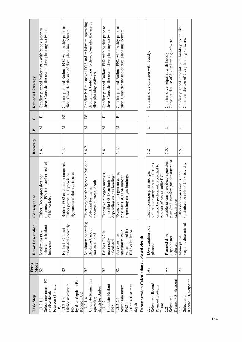
Task
Ste
p Er
ror
Mod
e Er
ror
Des
crip
tion
Con
sequ
ence
R
ecov
ery
P C
R
emed
ial S
trat
egy
1.3.
2.1.
1Se
lect
max
imum
PO
2 at
div
e de
pth
betw
een
(1.4
and
1.6)
S2
Max
imum
PO
2se
lect
ed fo
r bai
lout
inco
rrect
Eith
er, D
ecom
pres
sion
not
optim
ised
(PO
2 to
o lo
w) o
r ris
k of
CN
S to
xici
ty.
5.4.
1 M
B
! C
onfir
m p
lann
ed b
ailo
ut P
O2
with
bud
dy p
rior t
odi
ve. C
onsi
der t
he u
se o
f div
e pl
anni
ng s
oftw
are.
1.3.
2.1.
3D
ivid
e m
axim
umPO
2by
div
e de
pth
in B
ar.
Rec
ord
FO2
R2
Bai
lout
FO
2 no
tca
lcul
ated
cor
rect
ly
Bai
lout
FO
2 ca
lcul
atio
n in
corre
ct.
Eith
er p
oten
tial H
ypox
ia o
rH
yper
oxia
if B
ailo
ut is
use
d.
5.4.
1 M
B
!!
Con
firm
pla
nned
Bai
lout
FO
2 w
ith b
uddy
prio
r to
dive
. Con
side
r the
use
of d
ive
plan
ning
sof
twar
e.
1.3.
2.1.
4C
alcu
late
Min
imum
oper
atin
gde
pth
for B
ailo
ut
R2
Min
imum
ope
ratin
gde
pth
for b
ailo
utno
t cal
cula
ted
Div
er m
ay b
reat
he h
ypox
ic b
ailo
ut.
Pote
ntia
l for
inst
ant
unco
nsci
ousn
ess,
dea
th.
5.4.
2 M
B
!!
Con
firm
bai
lout
mix
es F
O2
and
min
imum
ope
ratin
gde
pths
with
bud
dy p
rior t
o di
ve. C
onsi
der t
he u
se o
fdi
ve p
lann
ing
softw
are.
1.3.
2.2.
Cal
cula
te B
ailo
utFN
2
R2
Bai
lout
FN
2 is
inco
rrect
lyca
lcul
ated
Exce
ssiv
e ni
troge
n na
rcos
is,
poss
ible
IBC
D o
n ba
ilout
depe
ndin
g on
gas
load
ings
5.4.
1 M
B
! C
onfir
m p
lann
ed B
ailo
ut F
N2
with
bud
dy p
rior t
odi
ve. C
onsi
der t
he u
se o
f div
e pl
anni
ng s
oftw
are.
1.3.
2.2.
1Se
lect
max
imum
PN2
of3.
0 to
4.0
at m
axde
pth
S2
An
exce
ssiv
em
axim
um P
N2
valu
e is
use
d fo
rFN
2 ca
lcul
atio
n
Exce
ssiv
e ni
troge
n na
rcos
is,
poss
ible
IBC
D o
n ba
ilout
depe
ndin
g on
gas
load
ings
5.4.
1 M
B
! C
onfir
m p
lann
ed B
ailo
ut F
N2
with
bud
dy p
rior t
odi
ve. C
onsi
der t
he u
se o
f div
e pl
anni
ng s
oftw
are.
Dec
ompr
essi
on C
alcu
latio
ns –
clo
sed
circ
uit
2.1
Sele
ct a
nd R
ecor
dPl
anne
d B
otto
mT
ime
A8
Div
e du
ratio
n no
tpl
anne
d D
ecom
pres
sion
pla
n an
d ga
svo
lum
e co
nsum
ptio
n ca
lcul
atio
nsca
nnot
be
perfo
rmed
. Pot
entia
l to
run
out o
f gas
or s
uffe
r DC
I
5.2
L -
Con
firm
div
e du
ratio
n w
ith b
uddy
.
2.2
Sele
ct a
ndR
ecor
d PO
2 Se
tpoi
nt
A8
Plan
ned
dive
setp
oint
not
sele
cted
Una
ble
to c
ompl
ete
deco
mpr
essi
onpl
an (a
nd th
eref
ore
gas
cons
umpt
ion
calc
ulat
ions
5.5.
1 L
-C
onfir
m d
ive
setp
oint
with
bud
dy.
Con
side
r the
use
of d
ive
plan
ning
sof
twar
e.
2.2
Sele
ct a
ndR
ecor
d PO
2 Se
tpoi
nt
R2
Non
-opt
imal
setp
oint
det
erm
ined
Ei
ther
dec
ompr
essi
on is
not
optim
ised
or r
isk
of C
NS
toxi
city
5.
5.1
L !
Con
firm
pla
nned
set
poin
t with
bud
dy p
rior t
o di
ve.
Con
side
r the
use
of d
ive
plan
ning
sof
twar
e.
134

Task
Ste
p Er
ror
Mod
e Er
ror
Des
crip
tion
Con
sequ
ence
R
ecov
ery
P C
R
emed
ial S
trat
egy
2.3.
1D
iluen
t is
Air
Doe
s th
e di
ve ti
me
exce
ed th
e N
DL
for t
he p
lan
dept
han
d se
tpoi
nt?
R1
Req
uire
men
t for
Dec
ompr
essi
onpl
anni
ng n
otes
tabl
ishe
d
The
div
e pl
anne
d is
ade
com
pres
sion
div
e an
d th
is h
asno
t bee
n es
tabl
ishe
d.D
ecom
pres
sion
pla
nnin
g no
tco
nduc
ted;
gas
con
sum
ptio
nre
quire
men
ts fo
r dec
ompr
essi
on n
otde
term
ined
. Pot
entia
l DC
I or
drow
ning
.
5.5
M
! C
onfir
m d
ive
deco
mpr
essi
on p
lan
with
bud
dy.
Con
side
r the
use
of d
ive
plan
ning
sof
twar
e.
2.4.
5Pe
rform
Dec
ompr
essi
onC
alcu
latio
ns
R2
Div
er u
nder
take
sde
com
pres
sion
divi
ng w
ithou
tca
lcul
atin
gde
com
pres
sion
stop
s
Div
er re
lyin
g on
dec
ompr
essi
ondi
ve c
ompu
ter t
o ca
lcul
ate
deco
mpr
essi
on s
tops
. Fai
lure
of
equi
pmen
t lea
ds to
div
er n
otkn
owin
g w
hat s
ched
ule
to fo
llow
(Pot
entia
l DC
I). G
as re
quire
men
tsfo
r dec
ompr
essi
on n
ot e
stab
lishe
d,po
tent
ial t
o ha
ve in
suffi
cien
tqu
antit
ies
of O
2 av
aila
ble
(DC
I or
Hyp
oxia
, Dea
th).
5.5
M
! Pl
an a
ll de
com
pres
sion
div
es, h
ave
a w
ritte
nde
com
pres
sion
sch
edul
e if
dive
fails
. Con
side
rre
dund
ant d
ive
com
pute
rs a
nd/o
r ins
trum
enta
tion.
2.4.
5Pe
rform
Dec
ompr
essi
onC
alcu
latio
ns
R2
Inco
rrect
deco
mpr
essi
onsc
hedu
le c
alcu
late
d
DC
I. 5.
5.2
M
! C
onfir
m d
ecom
pres
sion
pla
n w
ith b
uddy
. Use
deco
mpr
essi
on s
oftw
are
(rath
er th
an d
ecom
pres
sion
tabl
es).
Car
ry a
nd m
onito
r div
e de
com
pres
sion
com
pute
rs.
2.4.
6R
ecor
dD
ecom
pres
sion
Sche
dule
-D
epth
and
du
ratio
n of
deco
mpr
essi
on s
tops
R2
Inco
rrect
deco
mpr
essi
onsc
hedu
le re
cord
ed
DC
I. 5.
5.2
L !
Con
side
r the
use
of d
ive
plan
ning
sof
twar
e di
rect
lypr
intin
g an
d la
min
atin
g de
com
pres
sion
sch
edul
es to
avoi
d co
pyin
g er
rors
. Cro
ss-c
heck
dec
ompr
essi
onsc
hedu
le w
ith b
uddy
.
Dec
ompr
essi
on C
alcu
latio
ns –
bai
lout
2.
5.1
Ass
ume
bailo
ut a
tla
stm
inut
e of
bot
tom
time
R2
Div
er d
oes
not
assu
me
bailo
utsi
tuat
ion
occu
rs a
tla
st m
inut
e of
botto
m ti
me
Cal
cula
tions
are
not
“w
orst-
case
sc
enar
io”,
dec
ompr
essi
onre
quire
men
t may
exc
eed
emer
genc
y de
com
pres
sion
pla
n
5.7
M
B!
Con
firm
div
e de
com
pres
sion
pla
n w
ith b
uddy
.C
onsi
der t
he u
se o
f div
e pl
anni
ng s
oftw
are.
135

Task
Ste
p Er
ror
Mod
e Er
ror
Des
crip
tion
Con
sequ
ence
R
ecov
ery
P C
R
emed
ial S
trat
egy
2.5.
5Se
lect
Dec
ompr
essi
onM
ix(e
s)
R2
Bai
lout
Dec
ompr
essi
onm
ixes
sel
ecte
d ar
eno
t opt
imal
Dec
ompr
essi
on ta
kes
long
er th
anne
cess
ary.
5.
7.1
M
-C
onsi
der d
ecom
pres
sion
sof
twar
e w
hich
reco
mm
ends
optim
al d
ecom
pres
sion
mix
es fo
r any
pla
nned
div
e.
2.5.
6Pe
rform
Dec
ompr
essi
onC
alcu
latio
ns
R2
Inco
rrect
bai
lout
deco
mpr
essi
onsc
hedu
le c
alcu
late
d
DC
I. 5.
7.2
M
B!
Con
firm
dec
ompr
essi
on p
lan
with
bud
dy. U
sede
com
pres
sion
sof
twar
e (ra
ther
than
dec
ompr
essi
onta
bles
).
2.5.
7R
ecor
dD
ecom
pres
sion
Sche
dule
-D
epth
and
du
ratio
n of
deco
mpr
essi
on s
tops
for c
hose
nde
com
pres
sion
mix
ture
s
R2
Inco
rrect
deco
mpr
essi
onsc
hedu
le re
cord
ed
DC
I. 5.
7.2
L !
Con
side
r the
use
of d
ive
plan
ning
sof
twar
e di
rect
lypr
intin
g an
d la
min
atin
g de
com
pres
sion
sch
edul
es to
avoi
d co
pyin
g er
rors
. Cro
ss-c
heck
bai
lout
deco
mpr
essi
on s
ched
ule
with
bud
dy.
Oxy
gen
Toxi
city
Con
side
ratio
ns
2.6.
1C
alcu
late
or
Rec
ord
Clo
sed
Circ
uit
CN
S To
xici
ty
R1
CN
S to
xici
ty ri
skig
nore
d C
NS
Con
vuls
ion,
Dro
wni
ng, D
eath
5.
8 M
!!
Con
firm
div
e de
com
pres
sion
pla
n w
ith b
uddy
.C
onsi
der t
he u
se o
f div
e pl
anni
ng/d
ecom
pres
sion
softw
are.
2.6.
1.2
Cal
cula
te C
NS
R2
CN
S to
xici
ty
inco
rrect
lyca
lcul
ated
CN
S C
onvu
lsio
n, D
row
ning
, Dea
th
5.8
M
!! C
onfir
m d
ive
deco
mpr
essi
on p
lan
with
bud
dy.
Con
side
r the
use
of d
ive
plan
ning
/dec
ompr
essi
onso
ftwar
e.
2.6.
2C
alcu
late
or
Rec
ord
CN
S To
xici
ty fo
rop
en c
ircui
t bai
lout
plan
R1
CN
S to
xici
ty fo
r ba
ilout
pla
nin
corre
ctly
calc
ulat
ed
CN
S C
onvu
lsio
n, D
row
ning
, Dea
th
5.8
M
!! C
onfir
m d
ive
deco
mpr
essi
on p
lan
with
bud
dy.
Con
side
r the
use
of d
ive
plan
ning
/dec
ompr
essi
onso
ftwar
e.
2.6.
3C
alcu
late
/ R
ecor
dC
lose
d C
ircui
tO
TUs
R1
OTU
s no
t tra
cked
Pu
lmon
ary
oxyg
en to
xici
ty.
Myo
pia.
N
one
M
! Em
phas
ise
durin
g tra
inin
g si
tuat
ions
whe
rePu
lmon
ary
oxyg
en to
xici
ty s
houl
d be
con
side
red.
136

Scru
bber
End
uran
ce
3.1
Ref
eren
ceM
anuf
actu
rers
dire
ctio
non
scr
ubbe
r dur
atio
ns
R1
Div
er d
oes
not
refe
renc
em
anuf
actu
rers
guid
ance
on
scru
bber
end
uran
ce
Scru
bber
end
uran
ce m
ay b
eex
ceed
ed. C
O2
Bre
akth
roug
h,H
yper
capn
ia. D
eath
/ B
ailo
ut
5.6
H
!! C
onsi
der p
rintin
g sc
rubb
er e
ndur
ance
info
rmat
ion
onth
e C
CR
uni
t, or
pub
lishi
ng w
ater
proo
f refe
renc
eca
rds f
or e
ssen
tial u
nit i
nfor
mat
ion.
Mak
e di
vers
awar
e th
at th
ey c
an b
e in
capa
cita
ted
with
out a
nyw
arni
ng s
ympt
oms
in h
igh
PCO
2, h
igh
PO2
envi
ronm
ents
(i.e
. no
oppo
rtuni
ty to
bai
lout
).In
corp
orat
e th
e te
achi
ng o
f the
dan
gers
of c
arbo
ndi
oxid
e na
rcos
is in
to C
CR
div
ing
cour
ses.
3.2
Ref
eren
ce p
lann
ed
dept
h
R2
Div
er d
oes
not
fact
or d
epth
into
scru
bber
end
uran
ceca
lcul
atio
n
Scru
bber
end
uran
ce m
ay b
eex
ceed
ed. C
O2
Bre
akth
roug
h,H
yper
capn
ia. B
ailo
ut.
5.6
H
!! Em
phas
is o
n po
int d
urin
g tra
inin
g. R
efer
to a
ndfo
llow
man
ufac
ture
r’s
guid
ance
to th
e le
tter.
Con
firm
scru
bber
dur
atio
n w
ith b
uddy
. Mak
e di
vers
aw
are
that
they
can
be
inca
paci
tate
d w
ithou
t any
war
ning
sym
ptom
s in
hig
h PC
O2,
hig
h PO
2 en
viro
nmen
ts(i.
e. n
o op
portu
nity
to b
ailo
ut).
Inco
rpor
ate
the
teac
hing
of t
he d
ange
rs o
f car
bon
diox
ide
narc
osis
in
to C
CR
div
ing
cour
ses.
3.2
Ref
eren
ce p
lann
edde
pth
R2
Div
er e
xcee
dsm
anuf
actu
rers
publ
ishe
d sc
rubb
erdu
ratio
n be
caus
ew
ater
is w
arm
or
low
wor
k ra
teas
sum
ptio
n
Scru
bber
end
uran
ce m
ay b
eex
ceed
ed. C
O2
Bre
akth
roug
h,H
yper
capn
ia. B
ailo
ut.
5.6
H
!! Tr
aini
ng/e
duca
tion
-alw
ays
be c
onse
rvat
ive
inca
lcul
atin
g sc
rubb
er d
urat
ion,
alw
ays
use
fresh
scru
bber
mat
eria
l for
dee
p an
d/or
col
d w
ater
div
es.
Mak
e di
vers
aw
are
that
they
can
be
inca
paci
tate
dw
ithou
t any
war
ning
sym
ptom
s in
hig
h PC
O2,
hig
hPO
2 en
viro
nmen
ts (i
.e. n
o op
portu
nity
to b
ailo
ut).
Inco
rpor
ate
the
teac
hing
of t
he d
ange
rs o
f car
bon
diox
ide
narc
osis
into
CC
R d
ivin
g co
urse
s.3.
3R
efer
ence
Scr
ubbe
rD
urat
ion
prev
ious
ly u
sed
R2
Use
of s
crub
ber o
npr
evio
us d
ive(
s) is
inco
rrect
ly fa
ctor
edin
to s
crub
ber
dura
tion
calc
ulat
ion
Scru
bber
end
uran
ce m
ay b
eex
ceed
ed. C
O2
Bre
akth
roug
h,H
yper
capn
ia. B
ailo
ut.
5.6
H
!! Tr
aini
ng/e
duca
tion
-alw
ays
be c
onse
rvat
ive
inca
lcul
atin
g sc
rubb
er d
urat
ion,
alw
ays
use
fresh
scru
bber
mat
eria
l for
dee
p an
d/or
col
d w
ater
div
es.
Mak
e di
vers
aw
are
that
they
can
be
inca
paci
tate
dw
ithou
t any
war
ning
sym
ptom
s in
hig
h PC
O2
high
PO2
envi
ronm
ents
(i.e
. no
oppo
rtuni
ty to
bai
lout
).In
corp
orat
e th
e te
achi
ng o
f the
dan
gers
of c
arbo
ndi
oxid
e na
rcos
is in
to C
CR
div
ing
cour
ses.
137

3.4
Con
firm
that
div
edu
ratio
n w
ill n
otex
ceed
Man
ufac
ture
r’s
reco
mm
enda
tions
R1
Rem
aini
ng s
crub
ber
endu
ranc
e is
estim
ated
cor
rect
ly;
how
ever
this
is n
otcr
oss
chec
ked
to in
wat
er ti
me
for t
hepl
anne
d di
ve.
Scru
bber
end
uran
ce m
ay b
eex
ceed
ed. C
O2
Bre
akth
roug
h,H
yper
capn
ia. B
ailo
ut.
5.5.
3 an
d5.
6 H
!!
Div
e co
nser
vativ
ely.
Con
firm
with
bud
dy. M
ake
dive
rs a
war
e th
at th
ey c
an b
e in
capa
cita
ted
with
out
any
war
ning
sym
ptom
s in
hig
h PC
O2,
hig
h PO
2 en
viro
nmen
ts (i
.e. n
o op
portu
nity
to b
ailo
ut).
Inco
rpor
ate
the
teac
hing
of c
arbo
n di
oxid
e na
rcos
isin
to C
CR
div
ing
cour
ses.
Gas
Con
sum
ptio
n –
Clo
sed
Cir
cuit
4.1.
1.1
Estim
ate
Oxy
gen
Met
abol
ism
(litr
espe
r min
ute)
incl
udin
g sa
fety
mar
gin
R2
Oxy
gen
met
abol
icra
te n
ot e
stim
ated
corre
ctly
with
appr
opria
te w
ork
rate
in e
mer
genc
ysi
tuat
ion.
Alth
ough
insu
ffici
ent o
n-bo
ard
Oxy
gen
to c
ompl
ete
the
dive
is a
ver
y se
rious
situ
atio
n, a
mis
take
on
litre
s of
O2
cons
umpt
ion
per m
inut
e is
unl
ikel
y to
caus
e an
erro
r res
ultin
g in
runn
ing
out o
fO
2 (d
ue to
so
muc
h ex
cess
O2
capa
city
carri
ed)
5.9.
1 L
! C
onfir
m O
2 ga
s pl
anni
ng w
ith b
uddy
. Car
ryre
dund
ant s
uppl
ies
of O
2 ca
pabl
e of
bei
ng p
lugg
edin
to C
CR
bre
athi
ng lo
op.
4.1.
1.2
Mul
tiply
O2
cons
umpt
ion
rate
by
plan
ned
in-w
ater
tim
e
R1/
R3
Oxy
gen
volu
me
requ
irem
ent n
otca
lcul
ated
corre
ctly
(in
wat
ertim
e no
tes
tabl
ishe
d or
calc
ulat
edco
rrect
ly)
Insu
ffici
ent o
n-bo
ard
Oxy
gen
toco
mpl
ete
the
dive
. Bai
lout
. 5.
9.1
M
! C
ritic
al fa
ctor
on
deep
div
es re
quiri
ng e
xten
sive
deco
mpr
essi
on. C
onfir
m O
2 ga
s pl
anni
ng w
ithbu
ddy.
Ens
ure
cylin
ders
are
fille
d ad
equa
tely
,m
onito
r O2
SPG
.
4.1.
1.5
Vol
ume
of O
2av
aila
ble
grea
ter t
han
O2
requ
ired
R1
Om
itted
che
ck to
esta
blis
h th
atav
aila
ble
volu
me
of O
2 is
suf
ficie
ntfo
r the
div
e.
Insu
ffici
ent o
n-bo
ard
Oxy
gen
toco
mpl
ete
the
dive
. Bai
lout
. 5.
9.1
M
! C
onfir
m O
2 ga
s pl
anni
ng w
ith b
uddy
. Ens
ure
cylin
ders
are
fille
d ad
equa
tely
, mon
itor O
2 SP
G.
4.1.
2.1
Estim
ate
volu
me
ofdi
luen
t req
uire
d
R1
Dilu
ent
requ
irem
ent n
otre
fere
nced
or
calc
ulat
edco
rrect
ly
Impl
icat
ions
for c
lear
ing
loop
floo
ds,
dilu
ent f
lush
es, b
uoya
ncy.
5.
9.2
M
-R
efer
to m
anuf
actu
rer’
s gu
idel
ines
and
trai
ning
agen
cy re
com
men
datio
ns.
Gas
Con
sum
ptio
n -O
pen
Cir
cuit
Bai
lout
138

4.2.
1C
alcu
late
/ R
ecor
dSu
rface
Air
Con
sum
ptio
n (S
AC
)ra
te
R1
SAC
rate
calc
ulat
edin
corre
ctly
(not
cons
erva
tive
enou
gh)
Ope
n ci
rcui
t bai
lout
gas
vol
ume
calc
ulat
ions
inac
cura
te. D
CI o
rD
row
ning
.
5.9.
3 M
B
!!
Cal
cula
te S
AC
rate
for t
rain
ee s
tude
nts
/ inc
orpo
rate
into
trai
ning
. Cal
cula
te c
onse
rvat
ivel
y. C
onsi
der t
heus
e of
div
e pl
anni
ng s
oftw
are
with
gas
vol
ume
calc
ulat
ion
func
tiona
lity.
4.2.
2.2
Ref
eren
ce b
ailo
utde
com
pres
sion
sto
pde
pths
and
tim
es (f
orea
ch b
ailo
ut m
ix)
R2/
R3
Bai
lout
deco
mpr
essi
onpl
an n
otca
lcul
ated
Gas
vol
ume
calc
ulat
ions
can
not b
epe
rform
ed. D
CI o
r Dro
wni
ng.
5.9.
3 M
B
!!
Con
firm
dec
ompr
essi
on p
lan
with
bud
dy. U
sede
com
pres
sion
sof
twar
e. C
arry
lam
inat
ed ta
bles
for
OC
bai
lout
. Use
div
e co
mpu
ters
.
4.2.
2.4
...Su
m fo
r eve
ryde
com
pres
sion
stop
dep
th
R1/
2 B
ailo
ut g
asqu
antit
y no
tco
rrect
lyca
lcul
ated
Ope
n ci
rcui
t bai
lout
gas
vol
ume
calc
ulat
ions
inac
cura
te. D
CI o
rD
row
ning
.
5.9.
3 M
B
!!
Con
firm
Bai
lout
gas
pla
nnin
g w
ith b
uddy
. Cal
cula
teco
nser
vativ
ely.
Con
side
r the
use
of d
ive
plan
ning
softw
are
with
gas
vol
ume
calc
ulat
ion
func
tiona
lity.
4.2.
3Fo
r eac
h ba
il ou
tm
ix.
Rec
ord
tota
l litr
esre
quire
d in
clud
ing
addi
tiona
l saf
ety
mar
gin
R2
Ade
quat
e le
vels
of
cons
erva
tism
not
built
into
ope
nci
rcui
t bai
lout
calc
ulat
ions
Ope
n ci
rcui
t bai
lout
gas
vol
ume
isin
suffi
cien
t. D
CI o
r dro
wni
ng.
5.9.
3 M
B
!!
Con
firm
Bai
lout
gas
pla
nnin
g w
ith b
uddy
. Cal
cula
teco
nser
vativ
ely.
Con
side
r the
use
of d
ive
plan
ning
softw
are
with
gas
vol
ume
calc
ulat
ion
func
tiona
lity.
4.2.
4.4
For e
ach
bailo
utm
ix, d
eter
min
e if
volu
me
of g
asav
aila
ble
is g
reat
erth
an v
olum
e of
gas
requ
ired
R1/
2 Ve
rify
bailo
utcy
linde
r cap
aciti
esan
d fil
l pre
ssur
esar
e su
ffici
ent f
orO
C b
ailo
ut
Ope
n ci
rcui
t bai
lout
gas
vol
umes
car
ried
not g
reat
er th
an p
lann
ed g
as v
olum
ere
quire
men
ts. P
oten
tial i
ssue
with
rent
alst
age
bottl
es, u
nfam
iliar
cap
acity
uni
tset
c. O
pen
circ
uit b
ailo
ut g
as v
olum
e is
insu
ffici
ent.
DC
I or d
row
ning
.
5.9.
3 L
B!!
Ed
ucat
ion
– co
nver
sion
of i
mpe
rial a
nd m
etric
capa
city
uni
ts, i
nfor
mat
ion
on re
adin
g of
cyl
inde
rca
paci
ties
on c
ylin
ders
.
139

Cro
ss-c
heck
of D
ive
Plan
with
Bud
dy (r
ecom
men
datio
n fo
r ad
ditio
nal t
ask)
5.0
Cro
ss-c
heck
Pla
n w
ith b
uddy
C1
Div
e pl
an is
not
chec
ked
with
bud
dypr
ior t
o di
ve
The
re a
re a
num
ber o
f asp
ects
of
chec
king
the
plan
with
a d
ive
budd
y. F
irstly
is th
e pl
an a
sge
nera
ted
erro
r fre
e (i.
e. n
o m
ista
kes
have
bee
n m
ade
in c
alcu
latio
n of
the
plan
). Se
cond
ly a
re th
e tw
o di
vepl
ans
in th
e bu
ddy
pair
sim
ilar t
oth
e ex
tent
that
they
can
be
cros
sch
ecke
d? C
ross
che
ckin
g re
lies
ondi
ve p
lann
ing
calc
ulat
ions
inde
pend
ently
mad
e an
d th
enre
fere
nced
aga
inst
eac
h ot
her.
No
oppo
rtuni
ty to
reco
ver f
rom
any
of th
e di
ve p
lann
ing
erro
rco
nseq
uenc
es d
escr
ibed
abo
ve –
su
ch a
s in
suffi
cien
t on-
boar
d ga
s (h
ypox
ia, d
eath
), in
suffi
cien
t bai
lout
(dro
wni
ng),
inco
rrect
ly c
alcu
late
dde
com
pres
sion
(DC
I), i
ncor
rect
lyca
lcul
ated
CN
S to
xici
ty (h
yper
oxia
,co
nvul
sion
s dr
owni
ng),
inco
rrect
lyca
lcul
ated
scr
ubbe
r dur
atio
n(h
yper
capn
ia, u
ncon
scio
usne
ss,
drow
ning
)
one
H
! En
cour
age
CC
R d
iver
s to
ope
rate
as
a te
am p
rior t
oen
terin
g th
e w
ater
. Con
side
r the
use
of d
ive
plan
ning
and
deco
mpr
essi
on s
oftw
are
to p
lan
dive
s an
dco
nsid
er a
ligni
ng p
lans
so
that
bud
dy te
ams
rem
ain
toge
ther
thro
ugho
ut th
e di
ve.
Con
side
r tea
chin
g bu
ddy
plan
ning
as
part
of C
CR
divi
ng c
ours
es.
5.3
Con
firm
Dilu
ent G
asFO
2, F
N2,
FH
e
C1
A m
ista
ke in
cho
ice
of d
iluen
t may
hav
ebe
en m
ade
and
the
erro
r not
trap
ped
Nitr
ogen
Nar
cosi
s, H
ypox
ia,
Hyp
erox
ia, i
ncre
ased
bre
athi
ngre
sist
ance
, exc
essi
ve D
ecom
pres
sion
requ
irem
ents
.
Non
e M
!!
Con
side
r the
use
of d
ive
plan
ning
sof
twar
e, o
r cro
ssre
fere
nce
your
div
e pl
an w
ith y
our b
uddy
.
5.4.
1C
onfir
m g
asFO
2, F
N2,
FH
e
C1
A m
ista
ke in
cho
ice
of b
ailo
ut m
ayha
ve b
een
mad
ean
d th
e er
ror n
ottra
pped
Nitr
ogen
Nar
cosi
s, H
ypox
ia,
Hyp
erox
ia, e
xces
sive
Dec
ompr
essi
on re
quire
men
ts.
Non
e M
!!
Con
side
r the
use
of d
ive
plan
ning
sof
twar
e, o
r cro
ssre
fere
nce
your
div
e pl
an w
ith y
our b
uddy
.
140

5.4.
2C
onfir
m M
inim
umO
pera
ting
Dep
th
C1
A m
ista
ke in
calc
ulat
ion
ofm
inim
um o
pera
ting
dept
h of
bai
lout
gas
may
hav
e be
enm
ade
and
the
erro
rno
t tra
pped
Hyp
oxia
, im
med
iate
unco
nsci
ousn
ess.
N
one
M
!! C
onsi
der t
he u
se o
f div
e pl
anni
ng s
oftw
are,
or c
ross
refe
renc
e yo
ur d
ive
plan
with
you
r bud
dy.
5.5.
1C
onfir
m s
etpo
int
C1
Setp
oint
sel
ectio
ner
ror n
ot tr
appe
d D
ecom
pres
sion
not
opt
imal
N
one
L -
Con
side
r the
use
of d
ive
plan
ning
sof
twar
e, o
r cro
ssre
fere
nce
your
div
e pl
an w
ith y
our b
uddy
.5.
5.2
Con
firm
Sto
p de
pths
and
times
C1
Inco
rrect
Dec
ompr
essi
on p
lan
not t
rapp
ed
Dec
ompr
essi
on p
lan
inco
rrect
for
dive
N
one
M
! C
onsi
der t
he u
se o
f div
e pl
anni
ng s
oftw
are,
or c
ross
refe
renc
e yo
ur d
ive
plan
with
you
r bud
dy.
5.5.
3C
onfir
mIn
-wat
er ti
me
C1
Tota
l in-
wat
er ti
me
calc
ulat
ion
erro
r not
trapp
ed
In w
ater
tim
e no
t cor
rect
lyca
lcul
ated
(may
impa
ct o
n sc
rubb
erdu
ratio
n re
quire
men
t)
Non
e M
-
Con
side
r the
use
of d
ive
plan
ning
sof
twar
e, o
r cro
ssre
fere
nce
your
div
e pl
an w
ith y
our b
uddy
.
5.6
Con
firm
Scr
ubbe
rD
urat
ion
C1
Scru
bber
dur
atio
nov
eres
timat
ion
erro
rno
t tra
pped
Hyp
erca
pnia
, con
fusi
on,
unco
nsci
ousn
ess.
N
one
M
!! C
onsi
der t
he u
se o
f div
e pl
anni
ng s
oftw
are,
or c
ross
refe
renc
e yo
ur d
ive
plan
with
you
r bud
dy.
5.7.
2C
onfir
m S
top
dept
hsan
d tim
es
C1
Bai
lout
deco
mpr
essi
onsc
hedu
le in
corre
ctan
d th
e er
ror n
ottra
pped
DC
I if b
ailo
ut u
sed
Non
e M
!
Con
side
r the
use
of d
ive
plan
ning
sof
twar
e, o
r cro
ssre
fere
nce
your
div
e pl
an w
ith y
our b
uddy
.
5.8
Con
firm
CN
STo
xici
ty
C1
CN
S to
xici
tyun
dere
stim
ated
and
the
erro
r not
trap
ped
CN
S co
nvul
sion
, dro
wni
ng, d
eath
. N
one
M
!! C
onsi
der t
he u
se o
f div
e pl
anni
ng s
oftw
are,
or c
ross
refe
renc
e yo
ur d
ive
plan
with
you
r bud
dy.
5.9.
1C
onfir
m O
2R
equi
red
C1
O2
volu
me
requ
irem
ent
unde
rest
imat
ed a
ndth
e er
ror n
ot tr
appe
d
Not
eno
ugh
O2
to c
ompl
ete
dive
N
one
M
!! C
onsi
der t
he u
se o
f div
e pl
anni
ng s
oftw
are,
or c
ross
refe
renc
e yo
ur d
ive
plan
with
you
r bud
dy.
5.9.
2C
onfir
m D
iluen
tR
equi
red
C1
Dilu
ent v
olum
ere
quire
men
tun
dere
stim
ated
and
the
erro
r not
trap
ped
Dilu
ent f
lush
not
ava
ilabl
e,po
tent
ial b
uoya
ncy
issu
es
Non
e M
!
Con
side
r the
use
of d
ive
plan
ning
sof
twar
e, o
r cro
ssre
fere
nce
your
div
e pl
an w
ith y
our b
uddy
.
5.9.
3C
onfir
m B
ailo
ut G
asre
quire
men
t
C1
Bai
lout
vol
ume
requ
irem
ent
unde
rest
imat
ed a
ndth
e er
ror n
ot tr
appe
d
Not
eno
ugh
bailo
ut to
com
plet
e th
edi
ve.
Non
e M
B
!!
Con
side
r the
use
of d
ive
plan
ning
sof
twar
e, o
r cro
ssre
fere
nce
your
div
e pl
an w
ith y
our b
uddy
.
141

142

APPENDIX 11: EXAMPLES OF CCR UNIT LOCKDOWN PROTOCOLS
A. QINETEQ AND HSL GUIDANCE PROVIDED BY GAVIN ANTHONY
GUIDANCE IN THE EVENT OF HANDLING DIVING EQUI PMENT POST ACCIDENT
Personal Safety
If mishandled, diving equipment can be hazardous to health. Do not place any person in a dangerous situation to recover any equipment. Diving equipment may contain gas at high pressure. Re-breathing equipment may contain hazardous chemicals. Diving equipment may be heavy, ensure when lifting equipment that correct handling techniques are used.
General Procedure
DO NOT DISMANTLE THE EQUIPMENT Record the following dive information:
• Date, time and location of incident. • Dive time and maximum depth of dive for the diver and any companions. • Dive plan, decompression schedules used and if completed correctly.
Try to handle the equipment as little as possible. Note and record on recovery of equipment:
• If buoyancy device or dry suit hoses are connected on recovery. • If equipment was damaged, prior to or during recovery. • Information displayed on a dive computer at time of recovery. • All pressure displays/gauges and record pressures. • Any details displayed on other electronic instruments.
Gather together and isolate all equipment involved in the accident, including: • Dive Slate/Logs covering previous 48 hours. • If available at least one other gas cylinder charged from the same source.
Attempt (do not force) to close all cylinder and isolator valves, note and record number of turns required for each valve (1 turn = 360°). Tape valves on cylinders and manifolds in the closed position. Tape any controls or valves on regulators, buoyancy devices and dry suits (including swivel inflation connections) in the position found to prevent any inadvertent movement.
Specific for re-breathers
All re-breather mouthpieces to be closed. The rebreather to be stored in an upright position. Close any automatic overpressure exhaust valves (note number of clicks or turns needed to close valve). Retain and keep with incident apparatus any samples of unused soda lime (from same batch) in the original container.
For storage and transportation
Allow any computer(s) to go into standby mode preferably by air-drying or switch computer off.
143

DO NOT
• Seal wet electronic equipment in plastic bag (a discharged battery can wipe any memory available).
• Leave valves open on cylinders. • Vent the gas in a cylinder prior to transport. • Move maximum depth recordings on analogue gauges. • Change position on any regulator controls.
B. GUIDANCE PROVIDED BY MARTIN PARKER OF AP DIVING
EQUI PMENT INSP ECTION FOLLOWING A DIVING INCIDENT. A step by step guide:
Photography:
It is absolutely essential to photograph everything. Sometime later when you are working through scenarios, you will need to know what was connected to what, which side each cylinder was, how close to his body was it mounted, did he have dive reel etc – the possibilities of future questions are endless and the photos taken at this stage could prove invaluable. I would strongly advise that the photographer be a separate person to the equipment examiner and ensure the photographer is briefed on getting a shot of everything both prior and during dis-assembly.
Record Keeping:
Again, it is absolutely essential to record everything you do and find. E.g. If you are inspecting the diluent side and find no fault then write “No fault found” – you are going to need this data later. The equipment inspection is a time for data collection – leave the analysis of the cause of the incident until afterwards, when you have all the data in and you have time to cross-reference with autopsy findings and statements.
Autopsy:
All too often a verdict of “death by drowning” is recorded. A proper autopsy can reveal much: Contact Dr M. Calder – [email protected]. Telephone: 01223 277220 – a pathologist specialising in deaths in water.
Recovery:
On the bottom:
The divers need to be briefed on what to look for: Does the diver have his mouthpiece in? Mask On?
Is he heavy on the bottom or semi-floating? Is there a beeping noise? If so –where is it coming from?
Are there any bubbles – if so where from? Ensure they do not touch the cylinder valves. Ensure they do not touch the handsets – If the diver is using a Classic Inspiration ask them to note whether the switches are towards the screen or towards the hose – on the diver’s left hand set and the diver’s right hand set – but don’t touch the switches. (The reason for asking this is to test for continuity of evidence). When they find the body, it’s likely to be a time of high stress for the rescue diver. Getting him to work to a checklist may help – but something to stress is that they are not to endanger themselves any more than a normal dive to that depth. I don’t think it is reasonable to bring the diver slowly to the surface - Simply attach a lift bag to the top handle of the rebreather, ensuring the diver is still in the harness properly and send him up.
144

Get statements from the divers as soon as possible after surfacing. The Police should be involved with this.
At the surface:
Once at the surface it is very common for the Police to take over. The best Police forces recover the body and equipment intact and follow a procedure similar to this, please communicate with them before the recovery if possible to ensure the continuity of evidence is assured. Try to get them to recover the body and equipment by holding the top handle and NOT the rear convoluted breathing hoses, the combined weight of the equipment and diver – they will pull the T piece fittings from the counterlungs! It will help if the diver can be recovered to the shore with equipment still attached. If the equipment can be kept on the diver when he is recovered lay him on his back and photo everything. Shots of the complete ensemble, shots of gauges, control valves, 1st stages, 2nd stages, rebreather front, back, side and top shots.
Equipment Inspection
Often the equipment inspector has no involvement until this stage. It is necessary to get some assurance from the Police that the equipment is received – as it was recovered from the water. If cylinder valves have been closed then it is necessary to get that information prior to your inspection. Try and read witness statements prior to doing the equipment inspection – was the diver red faced on recovery or did he have cyanosis?
Try and glean some information regarding the incident: Did the problem happen at the surface? – in which case High O2 is ruled out. How soon into the dive did the problem occur? – Try and get a copy of the download from his dive computer.
Important Notes: Classic Inspiration: never switch on both handsets. Each handset has separate information which can be gleaned. Inspect one handset, switch off and then switch on the other handset.
Vision Inspiration and Evolution: the dive data must be downloaded before the unit is submerged again. If you switch the unit on and submerge the unit below 1.2m it will start to record over the top of the incident dive data ! The Vision stores in hard memory the dive info for nine hours of diving. It is stored in hard memory so even when the batteries die the information is retained. If the diver is submerged for some time, then it is the first nine hours that is retained in memory.
The rebreather’s job is to control CO2, PO2 and provide a breathing circuit – so those are the areas you need to concentrate on:
1) Is the loop intact? 2) Did the diver have a CO2 hit? Mouthpiece valves?/ CO2 bypassed the scrubber?/Scrubber
material? 3) Was the machine switched on? Was it capable of controlling the PO2? 4) From the circumstances - is it possible to determine whether high O2 or low O2 is most
likely to be the problem and is there evidence from the equipment examination to support one line of thought rather than another?
At the end – you may be simply required to state what you think is the most likely cause of the incident – but you will need to state whether there was anything in the equipment inspection to support that. I strongly suggest an opinion isn’t given until all the facts are gleaned. The order of equipment test may vary with the state the equipment is in. If the mouthpiece is closed and the product is in good condition, it may be appropriate to place on a breathing simulator for a CO2 challenge. Qinetiq at Alverstoke is the centre for such testing in the UK.
145

Work slowly and methodically: a) Examine the loop for air tightness (positive pressure test)
i) is the mouthpiece open or closed? ii) What is the pressure relief valve setting, fully open ( counter-clockwise), half open or
fully closed (clockwise)? iii) note if and where the loop is leaking
b) If a strip down is necessary, start with the gas cylinders, one by one:
i) identify which gauge is with which cylinder ii) note the pressure and photograph the gauge iii) identify which cylinder is connected to the ADV and manual inflators) iv) check the cylinder valves – are they open or closed ? (some get confused with inverted
cylinders – looking on the knob, clockwise is closed, anti-clockwise is open – sorry to state the obvious but this has been messed up on two separate equipment inspections that I know of – it seems the inverted cylinders may have caused confusion.)
v) if gas leaks from a fitting – close the cylinder valve immediately – and identify where the gas is leaking from:
a. is the 1st stage attached to the cylinder valve properly? b. Are all the hoses connected properly? c. Are any hoses damaged? d. Is the gas leaking from the 2nd stage? e. Is the 2nd stage intact? f. Basically identify and record what you find.
vi) analyse the gas for oxygen content and if appropriate for helium content vii) consider checking gas for oil and Carbon monoxide contamination with relevant Draeger
tubes viii) if the cylinder is empty – check for water – de-valve and empty into a measuring
jug, note the volume of water.
c) Examine the loop for constrictions, components inserted in the loop such as mouthpiece with small orifice, VR3 4th cell holder – is the convoluted hose kinked?, are any of the convoluted hoses kinked?
d) Remove the mouthpiece and hoses at the T pieces,
i. tip any liquids into a receptacle (extreme caution required – in the event of a pulmonary baratrauma (burst lung) there is potential for blood and body fluids to be in the exhale hose.)
ii. The non-return valves need to be tested for back leaks – consider very carefully how this is to be achieved – ideally it needs to be done prior to cleaning so connectors may need to be employed.
e) Check the counterlungs for water and empty into a measuring jug.
f) Remove the canister from the loop by disconnecting at the T pieces.
i) remove the lid ii) note if there is any liquid on top of the scrubber cartridge (if there is a volume of water
then this would imply there has been no CO2 bypassing the Sofnolime. Tip the liquid out, measuring and noting the volume.
iii) Check to see whether the scrubber spacer ring and O ring are in place and located correctly
iv) Push down on the scrubber cartridge – does it travel up and down freely? v) Remove Spacer, O ring and Sofnolime cartridge
146

vi) Measure the position of the bottom “spider” – it should be only just inside the scrubber cartridge.
vii) Insert the complete scrubber cartridge in a strong polythene bag and seal it with a polythene bag sealer. ( Even if soaked, it is possible to have the scrubber material analysed – contact Gavin Anthony – Qinetiq, Alverstoke: www.qinetiq.com .
viii) At this stage it is quite okay to remove the bottom spider and take a look at the material – what brand and grade is it? But, then simply screw the bottom spider back in place – under NO circumstances should the scrubber material be emptied.
ix) Try and impound the container with any unused scrubber material from the diver’s home. (This will be required by QinetiQ ( pronounced Kinetic)).
x) Try and glean some information from witnesses regarding the renewal of the Sofnolime. xi) Tip the moisture from the scrubber base into a measuring jug and note the volume.
Lid and Handset examination:
It is difficult to give a step by step guide for the lid and handset because much will depend on the condition of the components in the lid. If the lid was flooded for some time, then the batteries and battery contacts may be destroyed. The oxygen cells may not be functioning properly or even be functioning at all. The difficult part is trying to determine what damage was there at the time of the incident and what is a result of what happened after the incident. Just how much you re-build the power supply and oxygen cells depends on what you are trying to achieve. If the components need re-building by replacing components – are you really going to be able to prove anything ? e.g. on the Classic - if the handsets are badly flooded the electronic modules might be affected depended on how long they’ve been flooded – so you can rebuild the lid components to find the handsets don’t work – but where has that got you? With the Vision electronics – the priority is to power up the system so you can download the dive data. Using the LogViewer program a lot of information regarding the incident will be gleaned – so with the Vision it would be appropriate to re-build the entire power supply if necessary ( if an external (6 volt DC power source is used it is essential to guarantee the correct polarity – incorrect polarity will damage the electronics.) With the Classic there is very little data to be gleaned from the handsets. Slip the front covers off and inspect for water. If water is present it will have to be emptied and dried before any testing. The switch is unlikely to survive a flood. Are the handsets flooded due to a broken handset or has water passed down from the lid? Oxygen cells might recover if allowed to dry. Simply measure the voltage of the cell by using a digital voltmeter across the outside two pins. On the Co-axial style connectors it is essential to use a spare connector – push it onto the cell and place the DVM probes on the connector. Under no circumstances should the DVM probes be inserted down the centre of the cell’s co-xial connector – you will destroy the +ve contact. Measure the voltage of the batteries - noting which battery comes from which slot (Controller One’s battery is closest to the junction box on the Classic), Measure the voltage at rest and if live, under load – operating the solenoid. (I would use another solenoid for this test – simply bend the terminals on the solenoid out slightly so the terminals can bridge the battery contacts).
Classic Handset examination:
Note the position of the on/off switch on each handset. Try switching on one handset (and ONE handset ONLY!!). Make a note whether it fires up or not. DO NOT calibrate! Make a note of what the handset says – at this stage it is simply going through a diagnostic check and will advise which oxygen cells are out of range. Make a note of the Elapsed on Time. Switch off. Do the same with the 2nd handset. Assuming everything is in reasonable condition: Connect on some oxygen (from one of your cylinders) and see if the solenoid operates and adds oxygen, measure the O2 % - place the lid in a polythene bag, place an oxygen sensor inside the bag and feed out to your DVM.
147
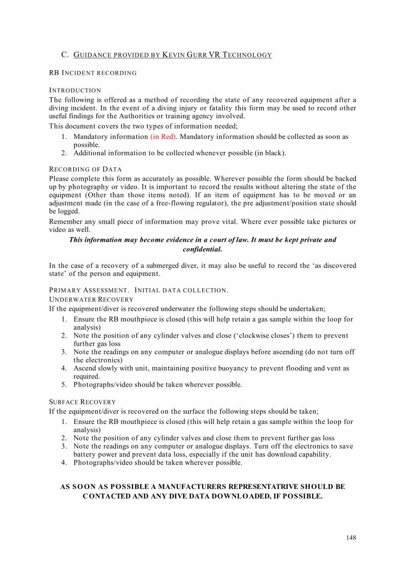
C. GUIDANCE PROVIDED BY KEVIN GURR VR TECHNOLOGY
RB INCIDENT RECORDING
INTRODUCTION
The following is offered as a method of recording the state of any recovered equipment after a diving incident. In the event of a diving injury or fatality this form may be used to record other useful findings for the Authorities or training agency involved. This document covers the two types of information needed;
1. Mandatory information (in Red). Mandatory information should be collected as soon as possible.
2. Additional information to be collected whenever possible (in black).
RECORDING OF DATA Please complete this form as accurately as possible. Wherever possible the form should be backed up by photography or video. It is important to record the results without altering the state of the equipment (Other than those items noted). If an item of equipment has to be moved or an adjustment made (in the case of a free-flowing regulator), the pre adjustment/position state should be logged. Remember any small piece of information may prove vital. Where ever possible take pictures or video as well.
This information may become evidence in a court of law. It must be kept private and confidential.
In the case of a recovery of a submerged diver, it may also be useful to record the ‘as discovered state’ of the person and equipment.
PRIMARY ASSESSMENT. INITIAL DATA COLLECTION. UNDERWATER RECOVERY
If the equipment/diver is recovered underwater the following steps should be undertaken; 1. Ensure the RB mouthpiece is closed (this will help retain a gas sample within the loop for
analysis) 2. Note the position of any cylinder valves and close (‘clockwise closes’) them to prevent
further gas loss 3. Note the readings on any computer or analogue displays before ascending (do not turn off
the electronics) 4. Ascend slowly with unit, maintaining positive buoyancy to prevent flooding and vent as
required. 5. Photographs/video should be taken wherever possible.
SURFACE RECOVERY
If the equipment/diver is recovered on the surface the following steps should be taken; 1. Ensure the RB mouthpiece is closed (this will help retain a gas sample within the loop for
analysis) 2. Note the position of any cylinder valves and close them to prevent further gas loss 3. Note the readings on any computer or analogue displays. Turn off the electronics to save
battery power and prevent data loss, especially if the unit has download capability. 4. Photographs/video should be taken wherever possible.
AS SO ON AS POSSIBLE A MANUFACTURERS REPRESENTATRIVE SHOULD BE CONTACTED AND ANY DIVE DATA DOWNLOADED, IF POSSIBLE.
148

Upon completion of this form the equipment should be placed in a secure container and not be tampered with again until collected by the recognised authority.
149

ON
SU
RFA
CIN
G R
ECO
RD
FO
RM
: RB
I-01
D
ECEM
BER
200
6.N
ote
Cop
ies
of t
his
docu
men
t are
con
fide
ntia
l and
may
be
used
as
evid
ence
. Ple
ase
supp
ly a
cop
y to
the
Polic
e or
Coa
st G
uard
upo
n re
ques
t.
Rec
orde
rs N
ame
Dat
e
Tim
e of
in
cide
nt/r
ecov
ery
Loc
atio
n of
in
cide
nt/r
ecov
ery
Vic
tim/c
asua
ltyna
me
(s)
Witn
ess/
Rec
over
ype
rson
nel
Con
tact
pho
ne (r
ecor
der)
Und
erw
ater
Situ
atio
n (n
ote
orie
ntat
ion
of d
iver
, any
ent
angl
emen
ts, e
quip
men
t mis
-pla
ced
etc.
)
Dep
th
Met
hod
of r
ecov
ery/
resc
ue
LIST
OF
EQU
IPM
EN
T
REC
OV
ERED
(Inc
lude
type
of s
uit/B
CD
)
Gas
labe
ls/id
enti
fyin
g m
arks
150

Ifva
lves
have
tobe
clos
ed,
posi
tions
prio
rto
clos
ure
mus
tbe
note
d.
REM
EMB
ERC
LO
CK
WIS
EC
LO
SES!
!
Cyl
inde
r1
Cyl
inde
r2
Cyl
inde
r3
Cyl
inde
r4
CY
LIN
DER
S
CY
LIN
DER
S
If
valv
es
have
to
be
cl
osed
,po
sitio
ns p
rior
to
clos
ure
mus
t be
note
d.
REM
EMB
ER
CL
OC
KW
ISE
C
LO
SES!
!
Gas
labe
ls/id
enti
fyin
g m
arks
Val
ve p
ositi
on (c
lose
and
use
clo
ck fa
ce r
efer
ence
as
a gu
ide)
Cyl
inde
r 1
Cyl
inde
r 2
Cyl
inde
r 3
Cyl
inde
r 4
Pres
sure
s
Cyl
inde
r 1
Cyl
inde
r 2
Cyl
inde
r 3
Cyl
inde
r 4
Reg
ulat
ors.
Not
e se
rial
num
bers
if
poss
ible
.T
ype
of r
egul
ator
Reg
1
Reg
2
Reg
3
Reg
4
Loc
atio
n of
reg
ulat
or
Reg
1
Reg
2
Reg
3
Reg
4
In m
outh
. H
ow s
tow
ed (
neck
tie
,st
owed
on
cy
linde
r,
depl
oyed
). N
ote
loca
tion
whe
n fo
und
if po
ssib
le.
Des
crib
e w
hich
reg
ulat
orto
whi
ch c
ylin
der.
151

Mas
k (r
emov
ed/d
islo
dged
/in p
lace
) N
ote
posi
tion
of
addi
tiona
l in
flat
ion
hose
s(a
ttach
ed/d
etac
hed
etc.
)
Reb
eath
er ty
peN
ote
disp
lay
read
ings
.
PO2.
D
epth
. T
ime
(as
exam
ples
). Ph
otog
raph
if
poss
ible
.
Ele
ctro
nics
fun
ctio
ning
? Y
/N
Mou
thpi
ece
open
/clo
sed
Mou
thpi
ece
in m
outh
?
Posi
tion
of
coun
terl
ung
dum
p va
lve
Posi
tion
of a
ny g
as is
olat
ion
valv
es
O2
AD
V
Suit/
BCD
infl
atio
n (c
onne
cted
?)
BCD
/RB
dam
age
152

Not
e an
y ot
her
equi
pmen
t da
mag
e/lo
ss.
Is
ther
e a
wei
ght
belt?
Con
ditio
n of
exp
osur
e su
it. N
ote
zip p
ositi
on in
dry
suits
.
Not
e po
sitio
n of
exh
aust
val
ve.
AD
DIT
ION
AL
NO
TE
S
153

APP
END
IX 1
2: H
IER
ARC
HIC
AL
TASK
AN
ALY
SES
FOR
NO
N-N
OR
MA
L O
PER
ATI
ON
S
1.0
Op
en
cir
cuit
ba
ilou
t
1.1
Lo
cate
(c
orr
ect
ga
s)
OC
re
gu
lato
r
1.2
Clo
se D
SV
1.4
Pla
ce O
C
reg
ula
tor
in m
ou
th
1.3
Re
mo
ve D
SV
1.7
Ch
eck
OC
reg
ula
tor
SP
G
1.6
Inh
ale
1. 5
Pu
rge
OC
reg
ula
tor
in m
ou
th
1.8
Sig
na
l bu
dd
y
NB
Thi
s is
inte
nded
to re
pres
ent a
gen
eric
pro
toco
l and
ther
e m
ay b
e va
riatio
ns a
ccor
ding
to C
CR
uni
t typ
e de
sign
(on
e un
it ty
pe, f
or e
xam
ple,
wou
ld re
quire
asw
itch
from
BO
V to
OC
whi
ch w
ould
elim
inat
e st
eps
1.1
to 1
.4).
EMER
GEN
CIE
S H
TA 1
: OPE
N C
IRC
UIT
BA
ILO
UT
154

2.4
.2.1
Rapid
incr
ease
in b
reath
ing r
esi
stance
Op
en
Cir
cu
it B
ailo
ut
2.1
Adopt ve
rtic
al
posi
tion
; lo
cate
DS
V
2.2
Pla
ce m
outh
pie
cein
mouth
2.4
Addre
ss
buoya
ncy
change
(add g
as)
2.4
.1
Dilu
ent add
2.4
.2
Loop flo
od
monito
ring
2.0
Lost
mouth
pie
ce /
loop flo
od
2.4
.2.2
Attem
pt to
cle
ar
loop
2.3
Exh
ale
EMER
GEN
CIE
S H
TA 2
: LO
ST M
OU
TH
PIEC
E / L
OO
P FL
OO
D
155

3.1
Dilu
ent flu
sh
3.2
Inhale
:
bre
ath
s 1
& 2
3.4
At 6
MS
W
ST
OP
3.3
Exh
ale
:
bre
ath
s 3
, 4
& 5
3.0
Sem
i-cl
ose
d c
ircu
it
mode
3.5
Go
to
OC
/open
loop
/
O2 C
CR
mode
NB
Thi
s pr
oced
ure
can
only
be
perfo
rmed
with
a fu
nctio
nal P
O2
mon
itorin
g sy
stem
EMER
GEN
CIE
S H
TA 3
: SE
MI-C
LO
SED
CIR
CU
IT M
OD
E
156

4.1
Ove
r pre
ssure
relie
f va
lve o
pen
4.2
P
ress
manual
dilu
ent in
flato
rbutton
4.0
D
iluent flu
sh
EMER
GEN
CIE
S H
TA 4
: DIL
UEN
T FL
USH
157
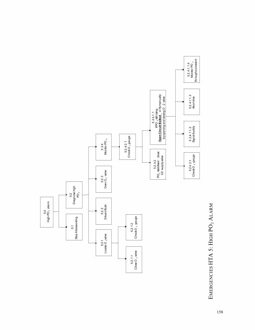
5.1
Sto
p if
de
sce
nd
ing
5.2
Dia
gn
ose
hig
h
PO
2
5.0
Hig
h P
O 2
a
larm
5.2
.2
Dilu
en
tflu
sh
5.2
.3
Ove
n O
2 va
lve
5.2
.1
Lo
cate
O 2
valv
e
5.2
.1.1
Clo
se O
2 v
alv
e
5.2
.1.2
Ch
eck
O 2
g
au
ge
5.2
.4
Mo
nito
r P
O 2
5.2
.4.1
.1
IfP
O 2
stil
l ris
ing
Op
en
Cir
cu
it B
ailo
ut
or
flym
an
ua
lly
by
op
en
ing a
nd c
losi
ng O
2 v
alv
e
5.2
.4.2
PO
2 st
ab
ilise
d :
clo
se
O2 s
up
ply
valv
e
5.2
.4.2
.1
Ch
eck
O 2
ga
ug
e
5.2
.4.1
.1.3
Ab
ort
div
e
5.2
.4.1
.1.2
Sig
na
l bu
dd
y
5.2
.4.1
.1.4
Mo
nito
r P
O 2
thro
ug
ho
uta
sce
nt
5.2
.4.2
.1
Ch
eck
O 2
g
au
ge
EMER
GEN
CIE
S H
TA 5
: HIG
H P
O2
ALA
RM
158

6.1
Op
en
Cir
cu
it
Bailo
ut
6.2
S
ignal b
uddy
6.3
S
tay o
ff the
loop
6.0
Bre
ath
less
ness
, W
OB
incr
ease
,
Headach
e, A
nxi
ety
, P
anic
. etc
.
Abort
div
e
EMER
GEN
CIE
S H
TA 6
: PH
YSI
OLO
GIC
AL
/ AFF
ECT
IVE
DIS
OR
DER
159
6.4

6.1
Sto
p if
asc
en
din
g
6.2
Ch
eck
ha
nd
sets
6.0
Lo
w P
O 2
ala
rm
6. 3
.2. 1
If P
O 2
st
ill lo
w
che
ckcy
lind
er
is
turn
ed
on
6.3
.2. 1
If P
O 2
in
cre
ase
s
ma
nu
ally
ad
d O
2
6. 3
. 2.1
. 1
Mo
nito
r P
O 2
con
tinu
ou
sly
6.3
. 2.1
. 1.1
. 1
Se
mi
-clo
se
d B
ailo
ut
or
Op
en
Cir
cu
it B
ailo
ut
6. 3
.2. 1
.2
Ab
ort
div
e
/
Op
en
Cir
cu
it
Ba
ilou
t
6. 3
Dia
gn
ose
low
PO
2
6. 3
.1
Ma
nu
ally
inje
ct O
2
6.3
.2
Mo
nito
r P
O 2
6. 3
.2. 1
.1
Ch
eck
ga
ug
e
6.3
. 2.1
. 2
Mo
nito
r P
O 2
6. 3
.2. 1
.1.1
Dilu
en
t ad
d
EMER
GEN
CIE
S H
TA 7
: LO
W P
O2
ALA
RM
160

8.0
Hig
h p
ress
ure
or
inte
rme
dia
te
pre
ssu
re fa
ilure
8.2
.2.1
Lo
cate
O 2
su
pp
ly
valv
e
8.2
.1.3
.1
Offb
oa
rd d
ilue
nta
vaila
ble
8.2
.1.3
.1.5
Sig
na
l bu
dd
y
8.2
.1.1
Lo
cate
dilu
en
t
sup
ply
valv
e
8.1
.5
Mo
nito
r S
PG
sfo
r
dilu
en
tan
d O
2
8.1
Sys
tem
dia
gn
osi
s
8.2
Le
ak
sou
rce
8.1
.2
Clo
se d
ilue
nt
sup
ply
valv
e
8.1
.3
Lo
cate
O 2
sup
ply
valv
e
8.1
.4
Clo
se O
2su
pp
lyva
lve
8.1
.1
Lo
cate
dilu
en
t
sup
ply
valv
e
8.1
.4.1
Le
ak
con
tinu
es :
tan
kO
-
rin
g o
r b
urs
tdis
kfa
ilure
8.1
.4.2
Le
ak
sto
ps :
1 st
sta
ge
ofL
P fa
ilure
8.1
.4.1
.2
Sig
na
l bu
dd
y
8.1
.4.1
.3
Ab
ort
div
e
8.1
.4.1
.1
Ba
ilo
ut
to
offb
oa
rd
OC
ba
ilo
ut
8.2
.1
Dilu
en
tsid
e le
ak
8.2
.2
O 2
sid
e le
ak
8.2
.1.2
Clo
se d
ilue
nt
sup
ply
valv
e
8.2
.1.3
Offb
oa
rd d
ilue
nt
ava
ilab
le ?
8.2
.1.3
.1.2
Dis
con
ect
inb
oa
rd
dilu
en
tLP
infla
tor
8.2
.1.3
.1.3
Co
nn
ect
offb
oa
rd d
ilue
nt
ho
se
8.2
.1.3
.1.4
Pre
ssd
ilue
nt
infla
tor
8.2
.1.3
.2
Offb
oa
rd d
ilue
ntn
ota
vaila
ble
8.2
.1.3
.1.1
Lo
cate
offb
oa
rd
dilu
en
t LP
infla
tor
ifa
vaila
ble
8.2
.1.3
.1.6
Ab
ort
div
e
8.2
.3.1
.5
Sig
na
l bu
dd
y
8.2
.3.1
.6
Ab
ort
div
e
8.2
.2.2
Clo
se O
2
sup
ply
valv
e
8.2
.2.3
Offb
oa
rd O
2
carr
ied
?
8.2
.2.3
.1
Offb
oa
rd O
2 a
vaila
ble
8.2
.2.3
.2
Offb
oa
rd O
2 n
ota
vaila
ble
8.2
.2.3
.1
Sig
na
l bu
dd
y
8. 2
.2.3
.2
Ab
ort
div
e
8.2
.2.3
.1.1
8.2
.2. 3
.1.2
8.2
.2.3
.1.3
Lo
cate
offb
oa
rdD
isco
nn
ect
curr
en
tC
on
ne
ct o
ffbo
ard
O2 L
P h
ose
L
P O
2 in
flato
r O
2 L
Ph
ose
8.2
.2.3
.1.4
Lo
cate
offb
oa
rd
O2 s
up
ply
valv
e
8. 2
.2.3
.1.5
O
pe
n O
2
Re
pe
atO
2 s
ou
rce
sup
ply
valv
e
failu
re
EMER
GEN
CIE
S H
TA 8
: HIG
H P
RES
SUR
E / I
NT
ER
ME
DIA
TE
PRES
SUR
E FA
ILU
RE
161
8.2
.2.3
.1.6

9.5
Ch
eck
SP
Gs
9.4
Ch
eck
PO
2
– a
re c
ells
resp
on
din
g a
se
xpe
cte
d
? (
Ra
pid
dro
p a
se
xha
le in
to C
CR
)
9.3
Pla
ce D
SV
in m
ou
th
,
reta
inin
g O
C b
ailo
ut
reg
ula
tor
in h
an
d
9.0
Re
turn
ing
to th
e lo
op
9.1
. 1
Ha
nd
sets
are
on
& in
div
e m
od
e
9.1
.2
No
ce
ll a
larm
s
9.2
Lo
cate
DS
V
9.1
PO
2 c
he
cks
9.6
Re
-se
cure
ba
ilou
t
reg
ula
tor
9.1
. 3
Ha
nd
sets
rea
din
g
PO
2 o
kay ?
EMER
GEN
CIE
S H
TA 9
: RE
TU
RN
ING
TO
TH
E LO
OP
162

APP
END
IX 1
3: S
HER
PA B
ASE
D A
NA
LYSE
S FO
R N
ON
-NO
RM
AL
OPE
RA
TIO
NS
1.
OPE
N C
IRC
UIT
BA
ILO
UT
Ope
n C
ircu
itB
ailo
ut T
ask
Step
E
rror
Mod
e E
rror
Des
crip
tion
C
onse
quen
ce
Rec
over
y P
C
Rem
edia
l Str
ateg
y
1.1
Loc
ate
OC
regu
lato
r A
6A
9 In
corr
ect s
elec
tion;
can
not f
ind
/de
ploy
W
rong
gas
for d
epth
– T
rimix
C
anno
t bai
l out
– A
ir
Incr
ease
d st
ress
& c
hoki
ng
1.2
1.2
M L ! !
Stay
on
rebr
eath
er a
nd d
iluen
t flu
sh
1.2
Clo
se D
SV
A8
Div
er fo
rget
s to
clo
se
Los
s of
buo
yanc
y; re
brea
ther
floo
ds
1.1
-Le
ave
it
1.3
Rem
ove
DSV
A
2 R
emov
ed b
efor
e O
C re
gula
tor
avai
labl
e D
iver
inha
les
wat
er
L !
Bet
ter t
rain
ing
Fit a
bai
lout
val
ve
1.4
Plac
e O
Cre
gula
tor i
n m
outh
A
9 Po
or k
it co
nfig
urat
ion
Can
not b
reat
he, e
tc
L !!
Find
a 2
nd O
C re
gula
tor /
bud
dy o
r ret
urn
tore
brea
ther
1.5
Purg
e O
Cre
gula
tor i
n m
outh
C
1A
8 N
o ga
s or
free
flow
; pos
sibl
em
outh
piec
e lo
ss
Can
not b
reat
he, e
tcW
ater
on
inha
latio
n L
!! Fi
nd a
2nd
OC
regu
lato
r / b
uddy
or r
etur
n to
rebr
eath
er
1.6
Inha
le
C1
No
gas
Can
not b
reat
he, e
tc
L !!
Find
a 2
nd O
C re
gula
tor /
bud
dy o
r ret
urn
tore
brea
ther
1.7
Che
ck O
Cre
gula
tor S
PG
C1
Failu
re to
che
ck
Poss
ibly
nil;
pos
sibl
y ru
n ou
t of g
asun
expe
cted
ly
L - !
Not
a p
robl
em in
itial
ly b
ut m
ay b
ecom
e a
prob
lem
late
r; sh
ould
be
part
of th
e O
C b
ailo
ut tr
aini
ng
1.8
Sign
al b
uddy
A
8 O
mitt
ing
actio
n L
Asc
end
imm
edia
tely
163

2.
LOST
MO
UT
HPI
ECE
/ LO
OP
FLO
OD
Los
t Mou
thpi
ece
/L
oop
Floo
d Ta
skSt
ep
Erro
rM
ode
Erro
rD
escr
iptio
n C
onse
quen
ce
Rec
over
y P
C
Rem
edia
l Str
ateg
y
2.1.
Loc
ate
DSV
; loo
kup
/ le
an b
ack
– ad
opt
vert
ical
pos
itio
n
Act
ion
Erro
r A
sphy
xiat
ion
and
drow
ning
L
!! Fi
nd O
C;
Prac
tice
drill
s re
com
men
ded
2.2
Plac
e mou
thpi
ece
inm
outh
A
9 A
sphy
xiat
ion
and
drow
ning
L
!! Pr
actic
e dr
ills
reco
mm
ende
d
2.3
Exha
le
A8
Om
ittin
gac
tion
Wat
er in
hala
tion
and
chok
ing;
lead
ing
to a
sphy
xiat
ion
and
drow
ning
M
!
Kee
p br
eath
ing;
Prac
tice
drill
s re
com
men
ded
2.4
Atte
mpt
to c
lear
lo
op
-
2.4.
1 D
iluen
t add
(aut
omat
ed o
r man
ual)
Aut
o –
C1
Man
ual –
A
8
AD
Vsw
itche
d of
f
No
dilu
ents
add
itio
n, n
o br
eath
able
gas v
olum
e. A
sphy
xiat
ion
and
drow
ning
L
! G
o op
en c
ircui
t;Pr
actic
e dr
ills
reco
mm
ende
d
2.4.
2 L
oop
flood
mon
itori
ng
C1
Nat
ural
cou
rse
– ju
st n
eed
toth
ink
abou
tw
ater
qua
ntity
Dep
ends
on
wat
er q
uant
ity
L - !
Go
open
circ
uit;
Prac
tice
drill
s re
com
men
ded
2.4.
2.1
Sudd
en c
hang
ein
buo
yanc
y -a
ddre
ss
A8
Om
ittin
gac
tion
Sink
ing
L !
Add
gas
to re
brea
ther
and
buo
yanc
y de
vice
in
extre
me c
ase
2.4.
2.2
Rap
id in
crea
sein
bre
athi
ng re
sist
ance
Ope
n ci
rcui
t bai
lout
A
8 D
iver
fails
toba
ilout
Incr
ease
d w
ork
for b
reat
hing
,in
crea
sed
CO
2 re
tent
ion.
Asp
hyxi
atio
n an
d dr
owni
ng
L !
Find
OC
;Pr
actic
e dr
ills
reco
mm
ende
d
164

3.
SEM
I-CLO
SED
CIR
CU
IT M
OD
E
Sem
i-clo
sed
circ
uit
mod
e Ta
sk S
tep
Err
orM
ode
Err
orD
escr
ipti
on
Con
sequ
ence
R
ecov
ery
P C
R
emed
ial S
trat
egy
3.1.
Dilu
ent f
lush
A
8 H
ypox
ia p
oten
tial H
IGH
M
!!
Rec
omm
end
the
use
of o
pen
circ
uit b
ailo
utin
stea
d
3.2
INH
AL
E br
eath
s 1
& 2
3.3
EXH
AL
E br
eath
s3,
4,5
thro
ugh
nose
3.4
At 6
MSW
STO
P
3.5
Go
to O
C /
open
loop
/ O
2 C
CR
mod
e
NB
Not
to b
e pr
actic
ed a
t air
dilu
ent –
bas
ic le
vel
165

4.
DIL
UE
NT
FLU
SH
Dilu
ent f
lush
Tas
k St
ep
Err
orM
ode
Err
orD
escr
ipti
on
Con
sequ
ence
R
ecov
ery
P C
R
emed
ial S
trat
egy
4.1.
Ove
r pre
ssur
e re
lief
valv
e (O
PRV
) ope
n A
8 G
ain
buoy
ancy
lead
ing
to ra
pid
asce
nt
L Ex
hale
pra
ctic
e dr
ills
4.3
Pres
s man
ual d
iluen
tin
flato
r but
ton
S2
Pres
s O
2 va
lve
by m
ista
ke
PO2
rise
lead
ing
to a
larm
s and
hy
pero
xia
M
-D
o co
rrec
t dilu
ents
flus
hPr
actic
e dr
ills
Aud
ible
ala
rm a
nd /
or h
ead
up d
ispl
ay (d
esig
nre
com
men
datio
n)
166

5.
HIG
H P
O2
ALA
RM
Hig
h PO
2 al
arm
Tas
kSt
ep
Err
orM
ode
Err
orD
escr
ipti
on
Con
sequ
ence
R
ecov
ery
P C
R
emed
ial S
trat
egy
5.1.
If d
esce
ndin
g –
stop
! A
8 PO
2 ri
ses f
urth
er; h
yper
oxia
L
!
5.2
Dia
gnos
e hi
gh P
O2
R3
Hyp
erox
ia
L !!
5.2.
1 L
ocat
e O
2 va
lve
5.2.
1.1
Clo
se O
2 va
lve
5.2.
1.2
Che
ck O
2 ga
uge
5.2.
2 D
iluen
t flu
sh
A8
Hyp
erox
ia
L - !
5.2.
3 O
pen
O2 v
alve
A
ctio
nEr
ror
Low
O2
alar
m e
vent
ually
L
!
5.2.
4 M
onito
r PO
2 R
3, C
1,C
2, C
5 H
ypox
ia; h
yper
oxia
L
!!
5.2.
4.1
Che
ck O
2 SP
G
Che
cker
ror
5.2.
4.1.
1 PO
2 st
abil
ised
:cl
ose
O2
supp
ly v
alve
A
3, A
8 H
yper
oxia
L
!
5.2.
4.1.
2 If
PO2
stil
l ri
sing
: Ope
n ci
rcui
tba
ilout
or f
ly u
nit
man
ually
by
open
ing
/cl
osin
g O
2 va
lve
A3,
A8
Act
ion
erro
rs
Hyp
erox
ia
L !1
Pr
actic
e dr
ills
5.2.
4.1.
2.1
Che
ck O
2 ga
uge
Che
cker
ror
167

5.2.
4.1.
2.2
Sign
al b
uddy
5.2.
4.1.
2.3
Abo
rt di
ve
5.2.
4.1.
2.4
mon
itor P
O2
cont
inua
lly d
urin
gas
cent
168

6.
PHY
SIO
LO
GIC
AL
/ AFF
ECT
IVE
DIS
OR
DER
Phys
iolo
gica
l /af
fect
ive
diso
rder
Tas
kSt
ep
Err
orM
ode
Err
orD
escr
ipti
on
Con
sequ
ence
R
ecov
ery
P C
R
emed
ial S
trat
egy
6.1.
Ope
n ci
rcui
tba
ilout
A
ctio
ner
rors
D
eter
iora
tion;
incr
easi
ng s
ympt
oms
M
! E
duca
tion,
pra
ctic
e dr
ills
6.2
Sign
al b
uddy
6.3
Stay
off
the
loop
L
! E
duca
tion,
pra
ctic
e dr
ills
6.4
Abo
rt di
ve
A2
L !
Edu
catio
n, p
ract
ice
drill
s
169

7.
LOW
PO
2 A
LAR
M
Low
PO
2 al
arm
Tas
kSt
ep
Err
orM
ode
Err
orD
escr
ipti
on
Con
sequ
ence
R
ecov
ery
P C
R
emed
ial S
trat
egy
7.1.
If a
scen
ding
: sto
p!
A8
Hyp
oxia
H
!!
Edu
catio
n
7.2
Che
ck h
ands
ets
Che
ckin
g er
rors
7.3.
Dia
gnos
e is
sue
low
PO2
R3
Hyp
oxia
L
!!
7.3.
1. M
anua
lly i
njec
tO
2 A
ctio
n an
dSe
lect
ion
erro
rs
L !!
7.3.
2 M
onito
r PO
2 C
heck
ing
erro
rs
Hyp
oxia
Hyp
erox
ia
L !!
7.3.
2.1
If PO
2 st
ill l
owch
eck
cylin
der i
s tu
rned
on 7.3.
2.1.
1 C
heck
gau
ge
Che
ckin
g er
rors
M
!!
7.3.
2.1.
1.1
Dilu
ent a
dd
Act
ion
and
Sele
ctio
n er
rors
H
ypox
ia
L !!
7.3.
2.1.
1.1.
1Se
mi-c
lose
d ba
ilout
or
Ope
n-ci
rcui
t bai
lout
7.3.
2.1.
2 M
onito
r PO
2 C
heck
ing
erro
rs
Hyp
oxia
Hyp
erox
ia
L !!
7.3.
2.2
If PO
2 in
crea
ses
man
ually
add
O2
Act
ion
and
Sele
ctio
n er
rors
7.3.
2.2.
1 M
onito
r PO
2co
ntin
uous
ly
Che
ckin
g er
rors
H
ypox
iaH
yper
oxia
L
!!
7.3.
2.2.
2 A
bort
dive
/O
pen-
circ
uit b
ailo
ut
170

8.
HIG
H P
RES
SUR
E / I
NT
ERM
ED
IAT
E PR
ESSU
RE
FAIL
UR
E
Hig
h pr
essu
re /
inte
rmed
iate
pre
ssur
efa
ilure
Tas
k St
ep
Err
orM
ode
Err
orD
escr
ipti
on
Con
sequ
ence
R
ecov
ery
P C
R
emed
ial S
trat
egy
8.1
Syst
em d
iagn
osis
8.1.
1 L
ocat
e di
luen
tsva
lve
S2
Leak
con
tinue
s L
-
8.1.
2 C
lose
dilu
ents
valv
e A
3 Le
ak c
ontin
ues
L -
8.1.
3 L
ocat
e O
2 va
lve
S2
Leak
con
tinue
s L
-
8.1.
4 C
lose
O2
valv
e A
3 Le
ak c
ontin
ues
L -
8.1.
4.1
Leak
con
tinue
s
8.1.
4.1.
1 B
ailo
ut to
offb
oard
ope
n-ci
rcui
t ba
ilout
L -
8.1.
4.1.
2 Si
gnal
bud
dy
I1
L -
8.1.
4.1.
3 A
bort
dive
L
-
8.1.
4.2
Leak
sto
ps
8.1.
5 M
onito
r SPG
s for
dilu
ents
and
O2
8.2
Leak
sou
rce
8.2.
1.1
Loca
te d
iluen
tva
lve
S2
171

8.2.
1.2
Clo
se d
iluen
tva
lve
A3
8.2.
1.3
Offb
oard
dilu
ent
avai
labl
e?
8.2.
1.3.
1 O
ffboa
rddi
luen
ts a
vaila
ble
8.2.
1.3.
1.1
Loc
ate
offb
oard
dilu
ent L
Pin
flato
r if a
vaila
ble
S2
Wro
ng g
as in
ject
ed in
to re
brea
ther
Ala
rms i
f hyp
erox
ic /
hypo
xic
L - !
Dis
conn
ect +
con
nect
to c
orre
ct g
as
8.2.
1.3.
1.2
Dis
conn
ect
inbo
ard
dilu
ent L
Pin
flato
r
S2
Non
e L
-
8.2.
1.3.
1.3
Con
nect
offb
oard
dilu
ent h
ose
A9
Non
e, p
rovi
ding
div
er is
not
desc
endi
ng; i
f des
cend
ing
ther
e is
pote
ntia
l for
lung
dam
age
L L - !
Push
dis
conn
ecto
r on
hard
er o
r asc
end
8.2.
1.3.
1.4
Pres
sdi
luen
ts in
flato
r A
9 B
utto
n pr
esse
dbu
t no
gas
Non
e, p
rovi
ding
div
er is
not
desc
endi
ng; i
f des
cend
ing
ther
e is
pote
ntia
l for
lung
dam
age
L -
Che
ck h
ose
conn
ectio
n +
chec
k if
offb
oard
cylin
der v
alve
is o
pen
8.2.
1.3.
1.5
Sign
al b
uddy
I1
L
-
8.2.
1.3.
1.6
Abo
rt di
ve
8.2.
1.3.
2 O
ffboa
rddi
luen
ts n
ot a
vaila
ble
8.2.
1.3.
2.1
Sign
al b
uddy
8.2.
1.3.
2.2
Abo
rt di
ve
8.2.
2 O
2 Si
de le
ak
8.2.
2.1
Loca
te O
2su
pply
val
ve
S2
Leak
con
tinue
s L
-
8.2.
2.2
Clo
se O
2 su
pply
valv
e A
3 Le
ak c
ontin
ues
L -
172

8.2.
2.3
Offb
oard
O2
carr
ied?
8.2.
2.3.
1 O
ffboa
rd O
2av
aila
ble
8.2.
2.3.
1.1
Loc
ate
offb
oard
O2
LP
hose
S2
W
rong
hos
ese
lect
ed
Wro
ng h
ose
wou
ld h
ave
low
er O
2co
nten
t and
lead
to b
uoya
ncy
prob
lem
sR
isk
of h
ypox
ic g
as b
eing
add
ed in
shal
low
s
L L - !
Mon
itor P
O2
disp
lays
; ven
t loo
p
8.2.
2.3.
1.2
Dis
conn
ect
curr
ent O
2 L
P in
flato
r S2
no
ne
L -
8.2.
2.3.
1.3
Con
nect
offb
oard
O2
LP
hose
A
9 N
one
prov
idin
g di
ver i
s no
tas
cend
ing;
if d
iver
asc
endi
ng th
ere
isri
sk o
f hyp
oxia
. If d
iver
con
tinue
sw
ithou
t che
ckin
g PO
2 th
ere
is ri
sk o
fhy
poxi
a
L !
Mon
itor P
o2 d
ispl
ays,
chec
ks
8.2.
2.3.
1.4
Loc
ate
offb
oard
O2
supp
lyva
lve
S2
Leak
con
tinue
s L
-
8.2.
2.3.
1.5
Ope
n O
2su
pply
val
ve
A3
No
gas a
ddit
ion
whe
n in
flato
r ope
ns
L -
Mon
itor P
O2
disp
lays
, ope
n O
2 va
lve
8.2.
2.3.
1.6
Rep
eat O
2so
urce
failu
re
8.2.
2.3.
2 O
ffboa
rd O
2no
t ava
ilabl
e
8.2.
2.3.
2.1
Sign
al b
uddy
I1
L
-
8.2.
2.3.
2.2
Abo
rt di
ve
173

9.
RE
TU
RN
ING
TO
TH
E LO
OP
Ret
urni
ng to
the
loop
Task
Ste
p E
rror
Mod
e E
rror
Des
crip
tion
C
onse
quen
ce
Rec
over
y P
C
Rem
edia
l Str
ateg
y
9.1
PO2
chec
ks
C1
Div
er fa
ils to
chec
k PO
2di
spla
y
PO2
coul
d be
at d
ange
rous
leve
ls
L !
Che
ck d
ispl
ay; d
iluen
ts fl
ush
9.1.
1 H
ands
ets
are
on
and
in d
ive m
ode
9.1.
2 N
o ce
ll al
arm
s
9.1.
3 H
ands
ets
read
ing
PO2
okay
?
9.2
Loc
ate
DSV
A
9 Po
tent
ial f
or d
row
ning
L
! R
etur
n to
ope
n-ci
rcui
t bai
lout
and
then
relo
cate
DSV
9.3
Plac
e D
SV in
mou
th,
reta
inin
g O
C
A1
Div
er fu
mbl
esdu
e to
lack
of
prac
tice
Pote
ntia
l for
dro
wni
ng
L !
Ret
urn
to o
pen-
circ
uit b
ailo
ut
9.4
Che
ck P
O2
– ar
ece
lls re
spon
ding
as
expe
cted
? R
apid
PO
2dr
op a
s exh
ale
into
CC
R
A1
Div
er fa
ils to
chec
k PO
2di
spla
y
PO2
coul
d be
at d
ange
rous
leve
ls
L !
9.5
Che
ck S
PGs
C1
Div
er fa
ils to
chec
k SP
Gs
Pote
ntia
l for
runn
ing
out o
f gas
L
!
9.6
Re-
secu
re b
ailo
utre
gula
tor
A4
Una
ble
to s
tow
agai
n N
one
L -
Ask
for a
ssis
tanc
e fro
m b
uddy
Published by the Health and Safety Executive 05/11

Health and Safety Executive
Assessment of manual operations and emergency procedures for closed circuit rebreathers
Closed Circuit Re-breather (CCR) diving has become increasingly popular as more sophisticated units enable diving for longer and at greater depths. CCR diving is much more complex than traditional open circuit diving in many ways and there is an increased potential for problems and diver errors to emerge. However, formal research examining CCR safety has been rare. To address this, the UK Health and Safety Executive commissioned the Department of Systems Engineering and Human Factors at Cranfield University to conduct a scoping study into the human factors issues relevant to CCR diving apparatus. The scoping study was designed to explore five principal subject areas: accident / incident analysis, unit assembly / disassembly, normal / non-normal diving operations, training needs analysis, interface and display. This scoping study has approached this with a series of studies each addressing separate issues that are relevant to the principal subject areas. These studies can be seen as potentially stand alone, each with its own objectives, method and results. These studies comprise; Accident / Incident Analysis; Human Error Potential Analysis: Assembly and Disassembly; Human Error Potential Analysis of Diving Operations; Training Needs Analysis; Interface and Display Recommendations and Human Error Potential in Non-Normal Operations.
This report and the work it describes were funded by the Health and Safety Executive (HSE). Its contents, including any opinions and/or conclusions expressed, are those of the authors alone and do not necessarily reflect HSE policy.
RR871
www.hse.gov.uk