Embed Size (px)
Citation preview
7/16/2017
1
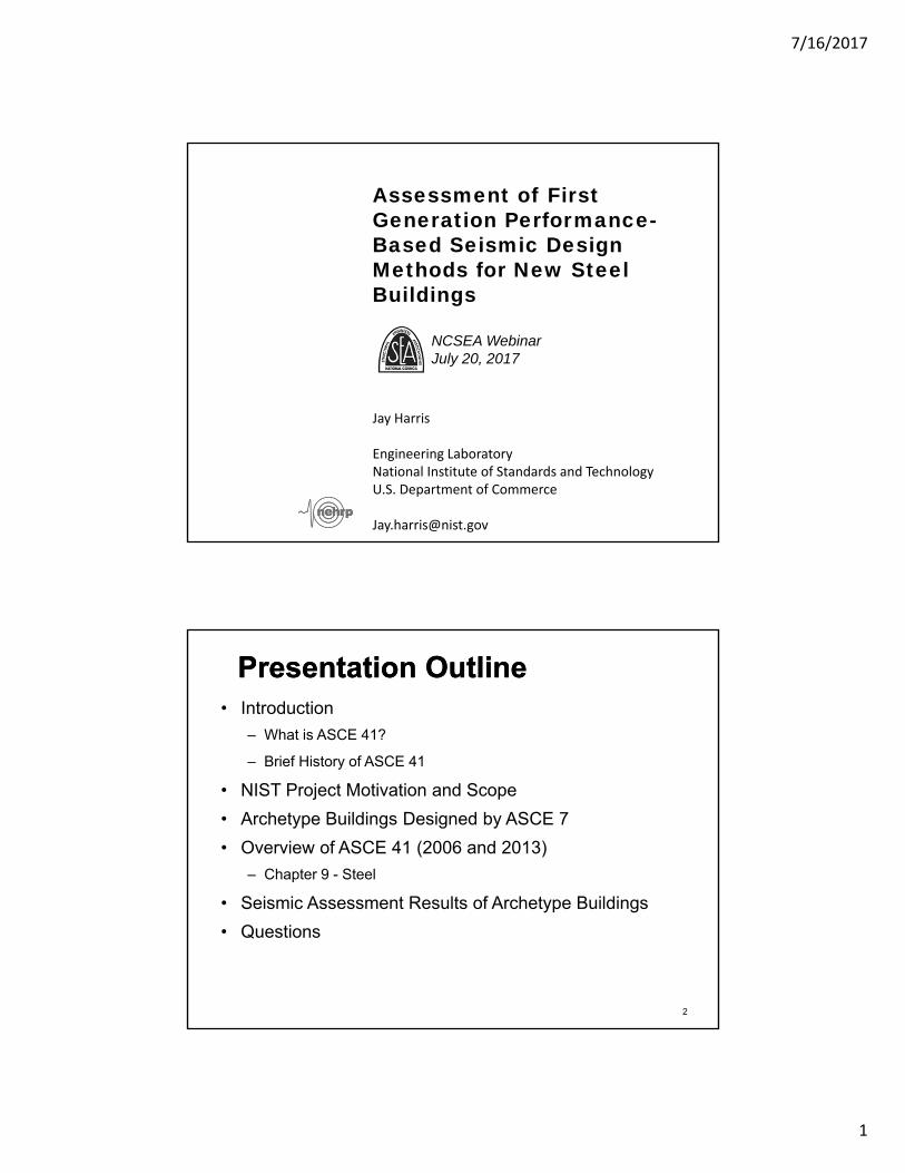
Assessment of First Generation Performance-Based Seismic Design Methods for New Steel Buildings
Jay Harris
Engineering LaboratoryNational Institute of Standards and TechnologyU.S. Department of Commerce
NCSEA WebinarJuly 20, 2017
Presentation OutlinePresentation Outline• Introduction
– What is ASCE 41?
– Brief History of ASCE 41
• NIST Project Motivation and Scope
• Archetype Buildings Designed by ASCE 7
• Overview of ASCE 41 (2006 and 2013)
– Chapter 9 - Steel
• Seismic Assessment Results of Archetype Buildings
• Questions
2
7/16/2017
2
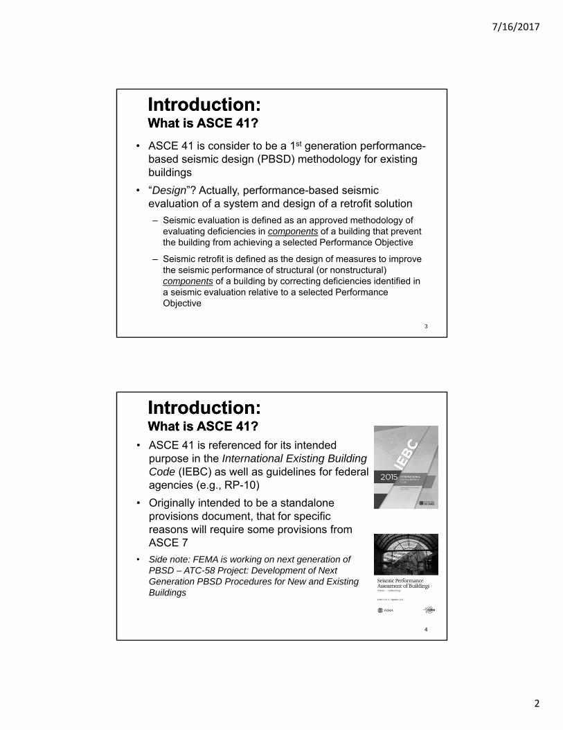
• ASCE 41 is consider to be a 1st generation performance-based seismic design (PBSD) methodology for existingbuildings
• “Design”? Actually, performance-based seismic evaluation of a system and design of a retrofit solution
– Seismic evaluation is defined as an approved methodology of evaluating deficiencies in components of a building that prevent the building from achieving a selected Performance Objective
– Seismic retrofit is defined as the design of measures to improve the seismic performance of structural (or nonstructural) components of a building by correcting deficiencies identified in a seismic evaluation relative to a selected Performance Objective
3
Introduction:What is ASCE 41?Introduction:What is ASCE 41?
• ASCE 41 is referenced for its intended purpose in the International Existing Building Code (IEBC) as well as guidelines for federal agencies (e.g., RP-10)
• Originally intended to be a standalone provisions document, that for specific reasons will require some provisions from ASCE 7
• Side note: FEMA is working on next generation of PBSD – ATC-58 Project: Development of Next Generation PBSD Procedures for New and Existing Buildings
4
Introduction:What is ASCE 41?Introduction:What is ASCE 41?

7/16/2017
3
• ASCE 41 is being used now for evaluation of existingsteel seismic force-resisting systems (SFRS) and theirpotential retrofit options– Mandatory - IEBC, federal or jurisdictional guidelines, etc.
– Voluntary - building owners
• ASCE 41 is a PBSD option for new buildings via Ch. 1of ASCE 7
• GSA PBS-P100: Facility Standards for the PublicBuildings Service requires ASCE 41 to be used for theseismic design of new GSA facilities and that theguidelines from ASCE 41 are intended to be applied tonew buildings
5
Introduction:Current Usage of ASCE 41?Introduction:Current Usage of ASCE 41?
• The National Institute of Building Sciences (NIBS) isusing PBS-P100 as the basis for developing theirNational Performance Based Design Guide
• ASCE 7-16 has a revised Ch. 16 for NonlinearResponse History Analysis (NLRHA) that referencesASCE 41 for component modeling, and allowablestrengths and deformations for components of adetermined SFRS
6
Introduction:Current Usage of ASCE 41?Introduction:Current Usage of ASCE 41?
7/16/2017
4
• 1997 – FEMA published FEMA 273: NEHRP Guidelines for the Seismic Rehabilitation of Buildings (and FEMA 274 - Commentary)
• 1998 – FEMA published FEMA 310: Handbook for Seismic Evaluation of Buildings
• 2000 – FEMA and ASCE published FEMA 356: Prestandard and Commentary for the Seismic Rehabilitation of Buildings—based on FEMA 356
– changes made to FEMA 273 are chronicled in FEMA 357: Global Topics Report on the Prestandard and Commentary for the Seismic Rehabilitation of Buildings
7
Introduction:History of ASCE 41Introduction:History of ASCE 41
• 2003 – ASCE published ASCE 31-03: Seismic Evaluation of Existing Buildings—based on FEMA 310
• 2007 – ASCE published ASCE 41-06: Seismic Rehabilitation of Existing Buildings—based on FEMA 356
• 2014 – ASCE published ASCE 41-13: Seismic Evaluation and Retrofit of Existing Buildings
– combines ASCE 31 and ASCE 41
• 2017 (or early 2018) – next version of ASCE 41
8
Introduction:History of ASCE 41Introduction:History of ASCE 41

7/16/2017
5
• ASCE 41 completed public review
• Papers are starting to be publically available about what revisions will be included in ASCE 41-17
• In regards to structural steel, many technical changes were approved this cycle. Several conference papers (SEAOC Convention, ASCE Structures Congress) discuss these changes. Future papers and reports will provide detailed explanations of the changes– Alignment between ASCE 41 and AISC 360 and AISC 341
• Component strengths, axial interaction effects
– Steel column provisions went through a major overhaul
– Material properties for tube steel were added
– Technical and editorial clean up process9
Introduction:Current Status of ASCE 41-17Introduction:Current Status of ASCE 41-17
Introduction:AISC 342
• Parallel with the ASCE 41-17 efforts, work is ongoing atAmerican Institute of Steel Construction (AISC) withinTask Committee 7 (TC-7) to develop a standard focusingon the seismic evaluation and retrofit of existingstructural steel buildings. This standard is currentlyreferred to as AISC 342: Seismic Evaluation and Retrofitof Structural Steel Buildings– work has highlighted differences between provisions for evaluation of a
structural steel component and provisions for design of the samecomponent in accordance with AISC 360 and AISC 341
– effort to align the standards where needed is important because ASCE41 is beginning to see use for the design of new steel buildings in orderto demonstrate seismic performance
10

7/16/2017
6
NIST Project
11
NIST Project Introduction:Project MotivationNIST Project Introduction:Project Motivation
• NIST GCR 09-917-2 identified a critical need to benchmark “first generation” PBSD
– Recent publications have also highlighted needs with ASCE 41
• Calibration/comparison with ASCE 7
• Investigate link between ASCE 7 and ASCE 41
– See ‘Current Status of ASCE 41’
– If a building is designed (ASCE 7) and built today, and then assessed (ASCE 41) tomorrow, will it need to be retrofitted?
12
7/16/2017
7
NIST Project Introduction:Project ScopeNIST Project Introduction:Project Scope
13
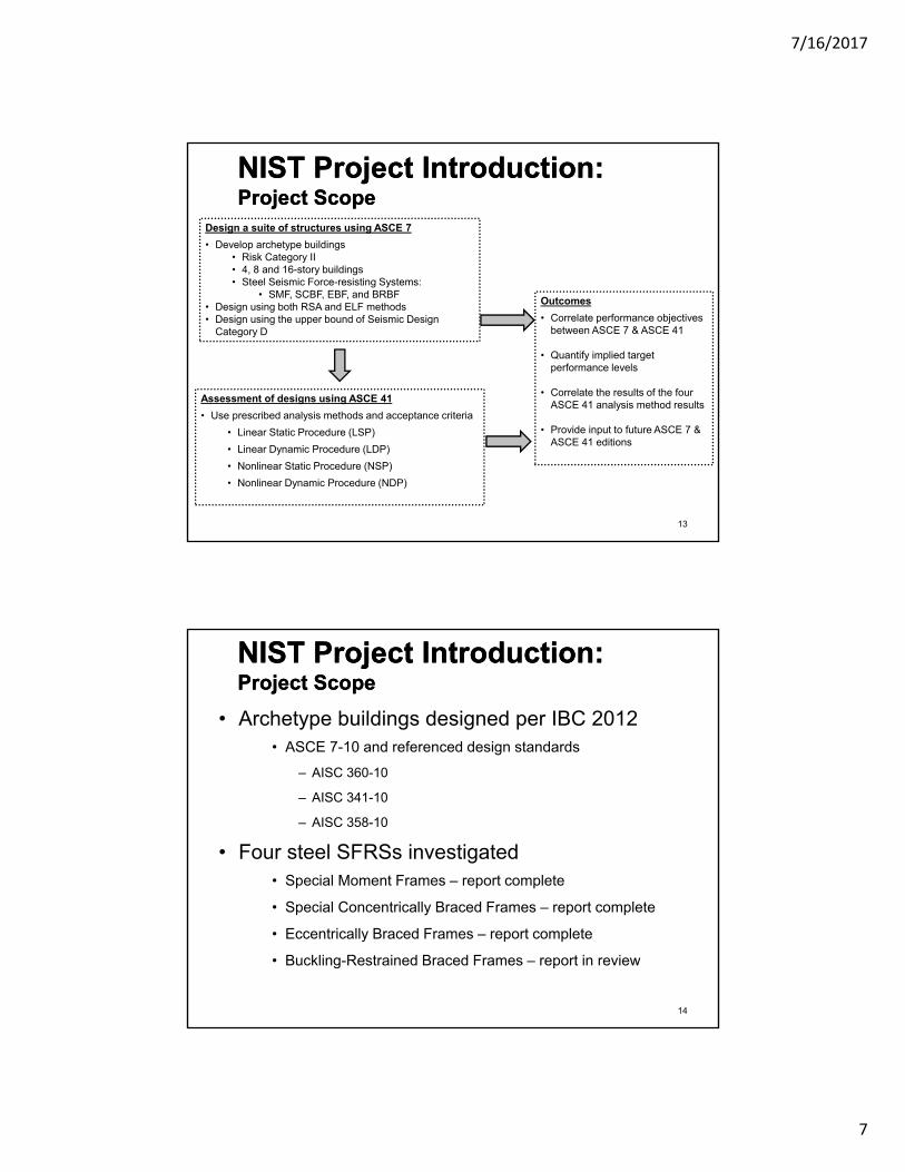
Design a suite of structures using ASCE 7
• Develop archetype buildings • Risk Category II• 4, 8 and 16-story buildings• Steel Seismic Force-resisting Systems:
• SMF, SCBF, EBF, and BRBF• Design using both RSA and ELF methods• Design using the upper bound of Seismic Design
Category D
Assessment of designs using ASCE 41
• Use prescribed analysis methods and acceptance criteria
• Linear Static Procedure (LSP)
• Linear Dynamic Procedure (LDP)
• Nonlinear Static Procedure (NSP)
• Nonlinear Dynamic Procedure (NDP)
Outcomes
• Correlate performance objectives between ASCE 7 & ASCE 41
• Quantify implied target performance levels
• Correlate the results of the four ASCE 41 analysis method results
• Provide input to future ASCE 7 & ASCE 41 editions
• Archetype buildings designed per IBC 2012• ASCE 7-10 and referenced design standards
– AISC 360-10
– AISC 341-10
– AISC 358-10
• Four steel SFRSs investigated• Special Moment Frames – report complete
• Special Concentrically Braced Frames – report complete
• Eccentrically Braced Frames – report complete
• Buckling-Restrained Braced Frames – report in review
NIST Project Introduction:Project ScopeNIST Project Introduction:Project Scope
14
7/16/2017
8
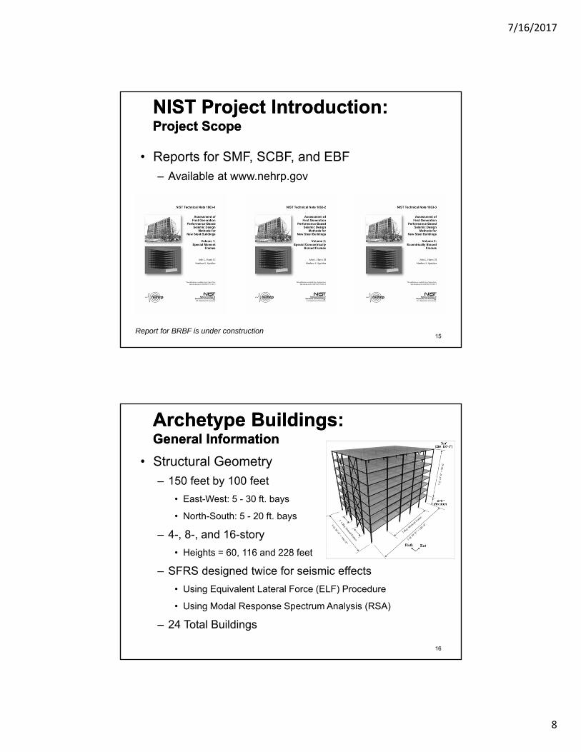
• Reports for SMF, SCBF, and EBF
– Available at www.nehrp.gov
NIST Project Introduction:Project ScopeNIST Project Introduction:Project Scope
15Report for BRBF is under construction
• Structural Geometry
– 150 feet by 100 feet
• East-West: 5 - 30 ft. bays
• North-South: 5 - 20 ft. bays
– 4-, 8-, and 16-story
• Heights = 60, 116 and 228 feet
– SFRS designed twice for seismic effects
• Using Equivalent Lateral Force (ELF) Procedure
• Using Modal Response Spectrum Analysis (RSA)
– 24 Total Buildings
Archetype Buildings:General InformationArchetype Buildings:General Information
16
7/16/2017
9
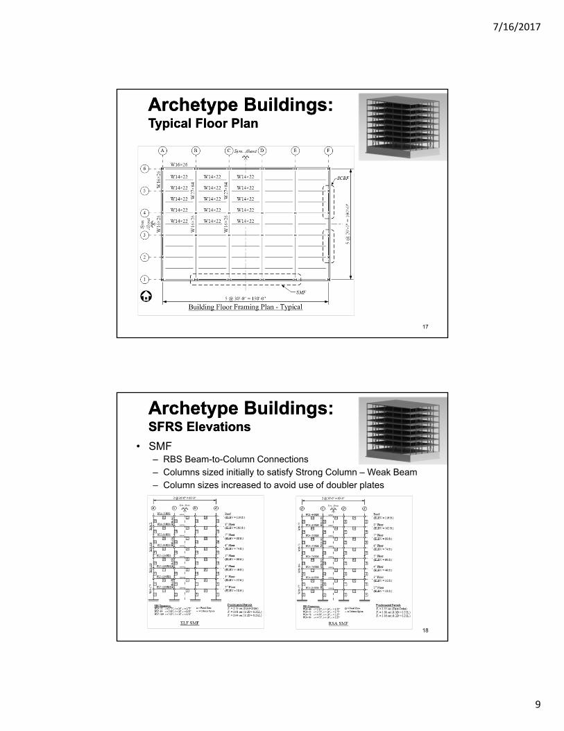
Archetype Buildings:Typical Floor PlanArchetype Buildings:Typical Floor Plan
17
• SMF– RBS Beam-to-Column Connections
– Columns sized initially to satisfy Strong Column – Weak Beam
– Column sizes increased to avoid use of doubler plates
Archetype Buildings:SFRS ElevationsArchetype Buildings:SFRS Elevations
18

7/16/2017
10
• SCBF– 4-story uses chevron bracing configuration
– 8- and 16-story use two-story X configuration
– Column sizes controlled by capacity design requirements
Archetype Buildings:SFRS ElevationsArchetype Buildings:SFRS Elevations
19
• EBF– Links are classified as “short”, e = 30” to 39”
– Capacity design requirements generally controlled column sizes
– Link rotation (i.e., drift) requirements controlled for taller frames
Archetype Buildings:SFRS ElevationsArchetype Buildings:SFRS Elevations
20
7/16/2017
11
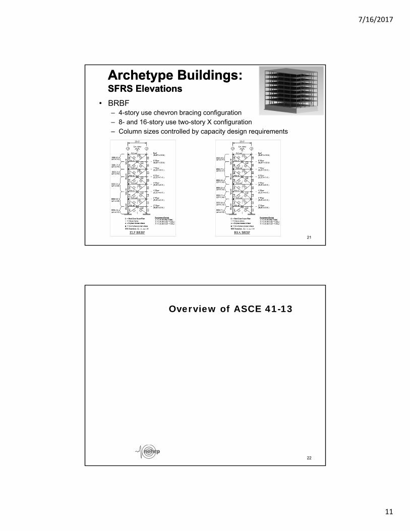
• BRBF– 4-story use chevron bracing configuration
– 8- and 16-story use two-story X configuration
– Column sizes controlled by capacity design requirements
Archetype Buildings:SFRS ElevationsArchetype Buildings:SFRS Elevations
21
Overview of ASCE 41-13
22
7/16/2017
12
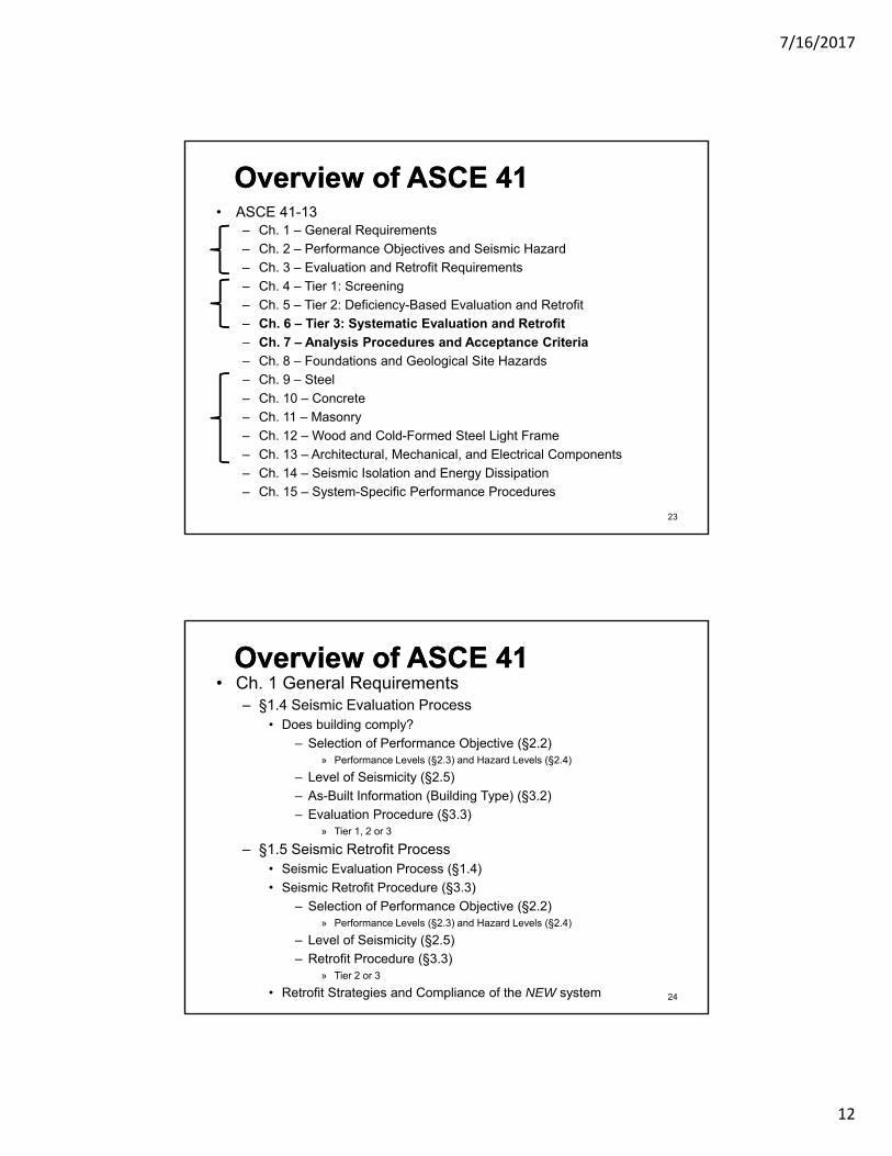
Overview of ASCE 41Overview of ASCE 41• ASCE 41-13
– Ch. 1 – General Requirements
– Ch. 2 – Performance Objectives and Seismic Hazard
– Ch. 3 – Evaluation and Retrofit Requirements
– Ch. 4 – Tier 1: Screening
– Ch. 5 – Tier 2: Deficiency-Based Evaluation and Retrofit
– Ch. 6 – Tier 3: Systematic Evaluation and Retrofit
– Ch. 7 – Analysis Procedures and Acceptance Criteria
– Ch. 8 – Foundations and Geological Site Hazards
– Ch. 9 – Steel
– Ch. 10 – Concrete
– Ch. 11 – Masonry
– Ch. 12 – Wood and Cold-Formed Steel Light Frame
– Ch. 13 – Architectural, Mechanical, and Electrical Components
– Ch. 14 – Seismic Isolation and Energy Dissipation
– Ch. 15 – System-Specific Performance Procedures
23
Overview of ASCE 41Overview of ASCE 41• Ch. 1 General Requirements
– §1.4 Seismic Evaluation Process• Does building comply?
– Selection of Performance Objective (§2.2)» Performance Levels (§2.3) and Hazard Levels (§2.4)
– Level of Seismicity (§2.5)
– As-Built Information (Building Type) (§3.2)
– Evaluation Procedure (§3.3)» Tier 1, 2 or 3
– §1.5 Seismic Retrofit Process• Seismic Evaluation Process (§1.4)
• Seismic Retrofit Procedure (§3.3)
– Selection of Performance Objective (§2.2)» Performance Levels (§2.3) and Hazard Levels (§2.4)
– Level of Seismicity (§2.5)
– Retrofit Procedure (§3.3)» Tier 2 or 3
• Retrofit Strategies and Compliance of the NEW system 24
7/16/2017
13
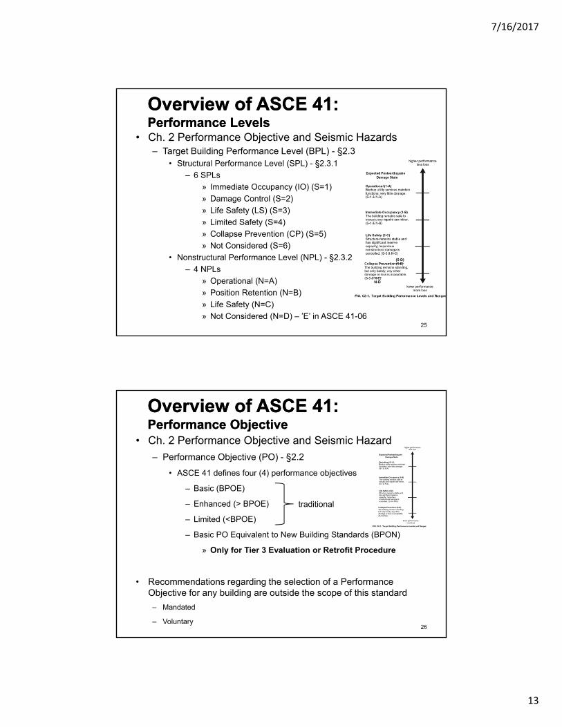
Overview of ASCE 41:Performance LevelsOverview of ASCE 41:Performance Levels
• Ch. 2 Performance Objective and Seismic Hazards– Target Building Performance Level (BPL) - §2.3
• Structural Performance Level (SPL) - §2.3.1
– 6 SPLs
» Immediate Occupancy (IO) (S=1)
» Damage Control (S=2)
» Life Safety (LS) (S=3)
» Limited Safety (S=4)
» Collapse Prevention (CP) (S=5)
» Not Considered (S=6)
• Nonstructural Performance Level (NPL) - §2.3.2
– 4 NPLs
» Operational (N=A)
» Position Retention (N=B)
» Life Safety (N=C)
» Not Considered (N=D) – ’E’ in ASCE 41-0625
(5-D)
N-D
Overview of ASCE 41:Performance ObjectiveOverview of ASCE 41:Performance Objective
• Ch. 2 Performance Objective and Seismic Hazard
– Performance Objective (PO) - §2.2
• ASCE 41 defines four (4) performance objectives
– Basic (BPOE)
– Enhanced (> BPOE)
– Limited (<BPOE)
– Basic PO Equivalent to New Building Standards (BPON)
» Only for Tier 3 Evaluation or Retrofit Procedure
• Recommendations regarding the selection of a Performance Objective for any building are outside the scope of this standard
– Mandated
– Voluntary26
traditional
7/16/2017
14
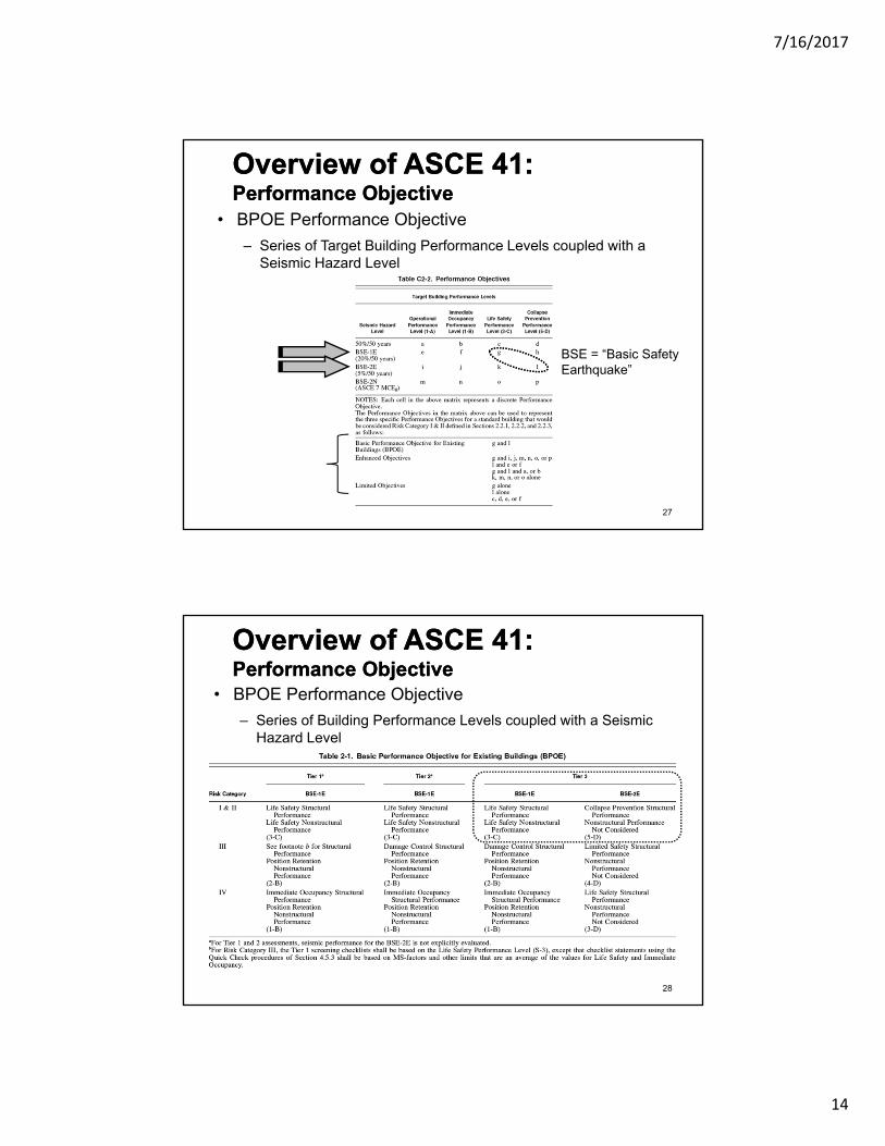
Overview of ASCE 41:Performance ObjectiveOverview of ASCE 41:Performance Objective
• BPOE Performance Objective
– Series of Target Building Performance Levels coupled with a Seismic Hazard Level
27
BSE = “Basic SafetyEarthquake”
Overview of ASCE 41:Performance ObjectiveOverview of ASCE 41:Performance Objective
• BPOE Performance Objective
– Series of Building Performance Levels coupled with a Seismic Hazard Level
28
7/16/2017
15
Overview of ASCE 41:Performance ObjectiveOverview of ASCE 41:Performance Objective
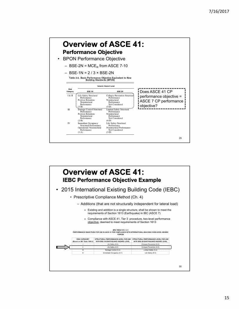
• BPON Performance Objective
– BSE-2N = MCER from ASCE 7-10
– BSE-1N = 2 / 3 × BSE-2N
Does ASCE 41 CP performance objective = ASCE 7 CP performance objective?
29
• 2015 International Existing Building Code (IEBC)• Prescriptive Compliance Method (Ch. 4)
– Additions (that are not structurally independent for lateral load)
» Existing and addition is a single structure, shall be shown to meet the requirements of Section 1613 (Earthquake) in IBC (ASCE 7)
» Compliance with ASCE 41, Tier 3 procedure, two-level performance objective, deemed to meet requirements of Section 1613
Overview of ASCE 41:IEBC Performance Objective ExampleOverview of ASCE 41:IEBC Performance Objective Example
30
7/16/2017
16
Overview of ASCE 41Seismic Hazard LevelOverview of ASCE 41Seismic Hazard Level
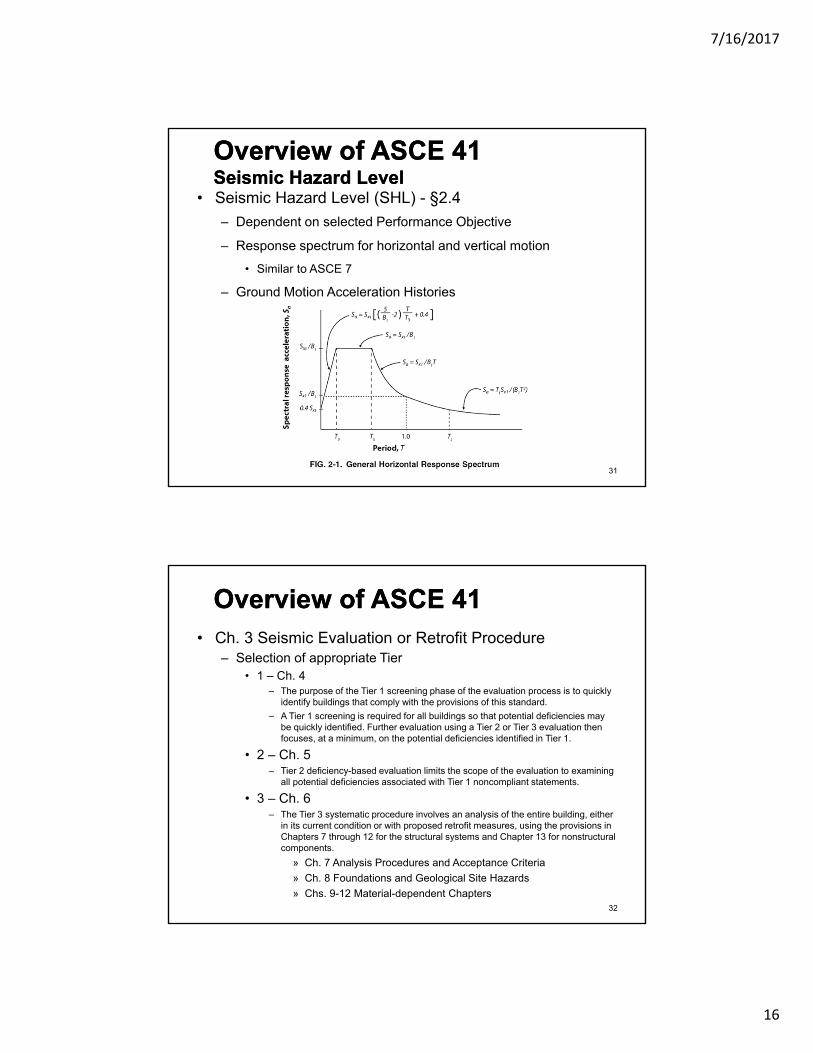
• Seismic Hazard Level (SHL) - §2.4
– Dependent on selected Performance Objective
– Response spectrum for horizontal and vertical motion
• Similar to ASCE 7
– Ground Motion Acceleration Histories
31
Overview of ASCE 41Overview of ASCE 41• Ch. 3 Seismic Evaluation or Retrofit Procedure
– Selection of appropriate Tier• 1 – Ch. 4
– The purpose of the Tier 1 screening phase of the evaluation process is to quickly identify buildings that comply with the provisions of this standard.
– A Tier 1 screening is required for all buildings so that potential deficiencies may be quickly identified. Further evaluation using a Tier 2 or Tier 3 evaluation then focuses, at a minimum, on the potential deficiencies identified in Tier 1.
• 2 – Ch. 5– Tier 2 deficiency-based evaluation limits the scope of the evaluation to examining
all potential deficiencies associated with Tier 1 noncompliant statements.
• 3 – Ch. 6– The Tier 3 systematic procedure involves an analysis of the entire building, either
in its current condition or with proposed retrofit measures, using the provisions in Chapters 7 through 12 for the structural systems and Chapter 13 for nonstructural components.
» Ch. 7 Analysis Procedures and Acceptance Criteria
» Ch. 8 Foundations and Geological Site Hazards
» Chs. 9-12 Material-dependent Chapters32
7/16/2017
17
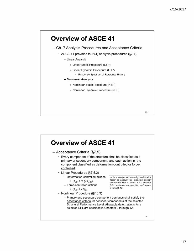
Overview of ASCE 41Overview of ASCE 41– Ch. 7 Analysis Procedures and Acceptance Criteria
• ASCE 41 provides four (4) analysis procedures (§7.4)
– Linear Analysis
» Linear Static Procedure (LSP)
» Linear Dynamic Procedure (LDP)
• Response Spectrum or Response History
– Nonlinear Analysis
» Nonlinear Static Procedure (NSP)
» Nonlinear Dynamic Procedure (NDP)
33
Overview of ASCE 41Overview of ASCE 41– Acceptance Criteria (§7.5)
• Every component of the structure shall be classified as a primary or secondary component, and each action in the component classified as deformation-controlled or force-controlled.
• Linear Procedures (§7.5.2)– Deformation-controlled actions
» QUD < m (QCE)
– Force-controlled actions
» QUF < QCL
• Nonlinear Procedure (§7.5.3)– Primary and secondary component demands shall satisfy the
acceptance criteria for nonlinear components at the selected Structural Performance Level. Allowable deformations for a selected SPL are specified in Chapters 9 through 12.
m is a component capacity modificationfactor to account for expected ductilityassociated with an action for a selectedSPL. m–factors are specified in Chapters9 through 12.
34

7/16/2017
18
Overview of ASCE 41Overview of ASCE 41– Alternative Modeling Parameters and Acceptance
Criteria (§7.6)
• Defines a method to derive the backbone curve (force-deformation) for a component and the associated target values for checking the acceptance criteria for nonlinear and linear assessment
35
Overview of Ch. 9Overview of Ch. 9• Ch. 9 Steel
– 9.1 Scope
– 9.2 Material Properties and Condition Assessment
– 9.3 General Assumptions and Requirements
– 9.4 Steel Moment Frames
– 9.5 Steel Braced Frames
– 9.6 Steel Plate Shear Walls
– 9.7 Steel Frame With Infills
– 9.8 Diaphragms
– 9.9 Steel Pile Foundations
– 9.10 Cast and Wrought Iron
36
7/16/2017
19
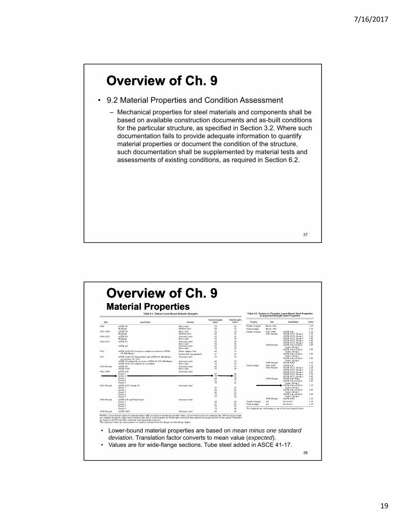
Overview of Ch. 9Overview of Ch. 9• 9.2 Material Properties and Condition Assessment
– Mechanical properties for steel materials and components shall be based on available construction documents and as-built conditions for the particular structure, as specified in Section 3.2. Where such documentation fails to provide adequate information to quantify material properties or document the condition of the structure, such documentation shall be supplemented by material tests and assessments of existing conditions, as required in Section 6.2.
37
Overview of Ch. 9Material PropertiesOverview of Ch. 9Material Properties
38
• Lower-bound material properties are based on mean minus one standard deviation. Translation factor converts to mean value (expected).
• Values are for wide-flange sections. Tube steel added in ASCE 41-17.

7/16/2017
20
Overview of Ch. 9Overview of Ch. 9• 9.3 General Assumptions and Requirements
– 9.3.1 Stiffness • Component stiffnesses shall be calculated in accordance with Sections 9.4 through 9.10.
– 9.3.2 Strength and Acceptance Criteria • Classification of steel component actions as deformation- or force- controlled and calculation
of strengths are specified in Sections 9.4 – 9.10.
• Strengths for deformation-controlled actions, QCE, shall be taken as expected strengths obtained experimentally or calculated using accepted principles of mechanics. Unless other procedures are specified in this standard, procedures contained in AISC 360 to calculate design strength shall be permitted, except that the strength reduction factor, , shall be taken as 1.0.
– Deformation capacities for acceptance of deformation-controlled actions are specified in Sections 9.4 – 9.10.
• Strengths for force-controlled actions, QCL, shall be taken as lower-bound strengths obtained experimentally or calculated using established principles of mechanics. Lower-bound strength shall be defined as mean strength minus one standard deviation. Unless other procedures are specified in this standard, procedures contained in AISC 360 to calculate design strength shall be permitted, except that the strength reduction factor, , shall be taken as 1.0.
39
Overview of Ch. 9Overview of Ch. 9• 9.4 – 9.10 System-specific provisions
– 9.4 Moment Frames – Fully and Partially Restrained
• 9.4.2.2 Stiffness of FR Moment Frames
– Linear and nonlinear procedures
– e.g. panel zone modeling – when should it be included?
For a beam in double curvature,
NDP: The complete hysteretic behavior of each component shall be determined experimentally or by other procedures approved by the authority having jurisdiction
40

7/16/2017
21
Overview of Ch. 9Overview of Ch. 9• 9.4 – 9.10 System-specific provisions
• 9.4.2.3 Strength of FR Moment Frames
– Linear and nonlinear procedures
– QCE and QCL of MF components (deformation- or force-controlled)
• 9.4.2.4 Acceptance Criteria for FR Moment Frames
– Linear and nonlinear procedures
– m-factors and allowable deformations of MF components for a given SPL
41
S = secondaryP = Primary
Overview of Ch. 9Overview of Ch. 9• m-factors for components in a moment frame
42

7/16/2017
22
Overview of Ch. 9Overview of Ch. 9
• m-factors for components in a moment frame
43
Overview of Ch. 9Overview of Ch. 9• Deformations for components in a moment frame
44

7/16/2017
23
Overview of Ch. 9Overview of Ch. 9• Deformations for components in a moment frame
45
Overview of Ch. 9Overview of Ch. 9• Deformations for components in a moment frame
46
7/16/2017
24
Assessment Results for the SFRS in the 8-Story Archetype Building
4- and 16-story can be found in NIST reports
47
Seismic Assessment:General Overview
• Performance objective– Basic Safety Objective (BPON in ASCE 41-13)
• Collapse Prevention Structural Performance Level at the BSE-2N (MCER in ASCE 7)
• Building Information– Type S1 (MF) and S2 (BF) with stiff diaphragms
• Tier 3 Evaluation Procedure (per Ch. 6)– Analysis Procedures (per Ch. 7)
• Linear Analysis– Linear Static Procedure (LSP)
– Linear Dynamic Procedure (LDP)
• Nonlinear Analysis– Nonlinear Static Procedure (NSP)
– Nonlinear Dynamic Procedure (NDP)
» 14 Ground Motions
48
7/16/2017
25
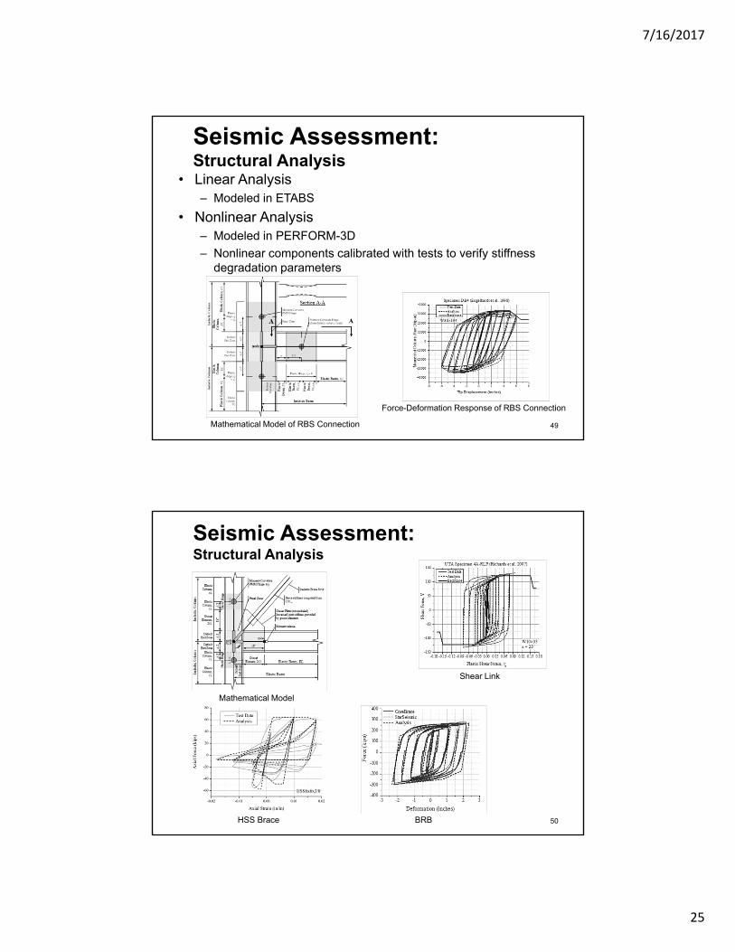
Seismic Assessment:Structural Analysis
• Linear Analysis– Modeled in ETABS
• Nonlinear Analysis– Modeled in PERFORM-3D
– Nonlinear components calibrated with tests to verify stiffness degradation parameters
49
Force-Deformation Response of RBS Connection
Mathematical Model of RBS Connection
Seismic Assessment:Structural Analysis
50HSS Brace
Shear Link
Mathematical Model
BRB

7/16/2017
26
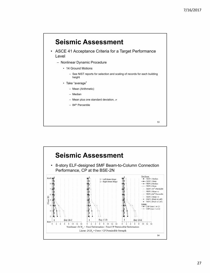
Seismic Assessment
• ASCE 41 Acceptance Criteria for a Target Performance Level
– Linear Assessment Procedures
• Deformation-Controlled Actions
• Force-Controlled Actions
51
Seismic Assessment• ASCE 41 Acceptance Criteria for a Target Performance
Level
– Nonlinear Assessment Procedures
• Deformation-Controlled Actions
• Force-Controlled Actions
52
7/16/2017
27
Seismic Assessment• ASCE 41 Acceptance Criteria for a Target Performance
Level
– Nonlinear Dynamic Procedure
• 14 Ground Motions
– See NIST reports for selection and scaling of records for each building height
• Take “average”
– Mean (Arithmetic)
– Median
– Mean plus one standard deviation,
– 84th Percentile
53
Seismic Assessment• 8-story ELF-designed SMF Beam-to-Column Connection
Performance, CP at the BSE-2N
54
7/16/2017
28
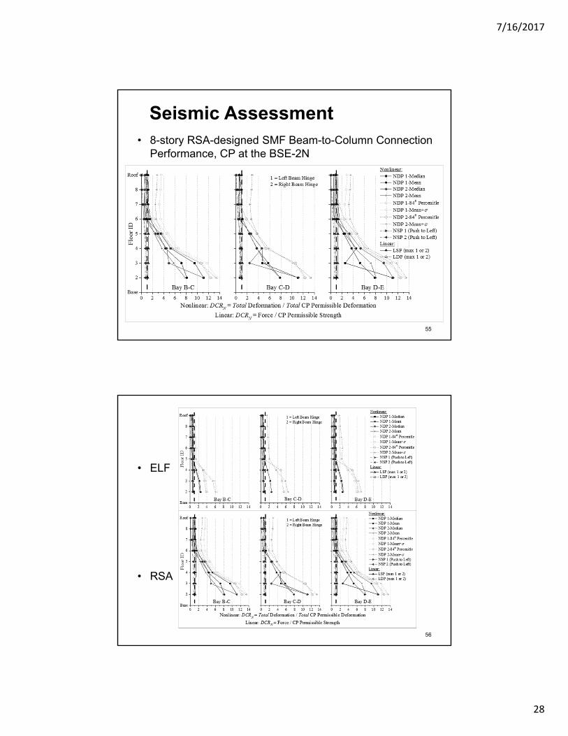
Seismic Assessment• 8-story RSA-designed SMF Beam-to-Column Connection
Performance, CP at the BSE-2N
55
• ELF
• RSA
56
7/16/2017
29
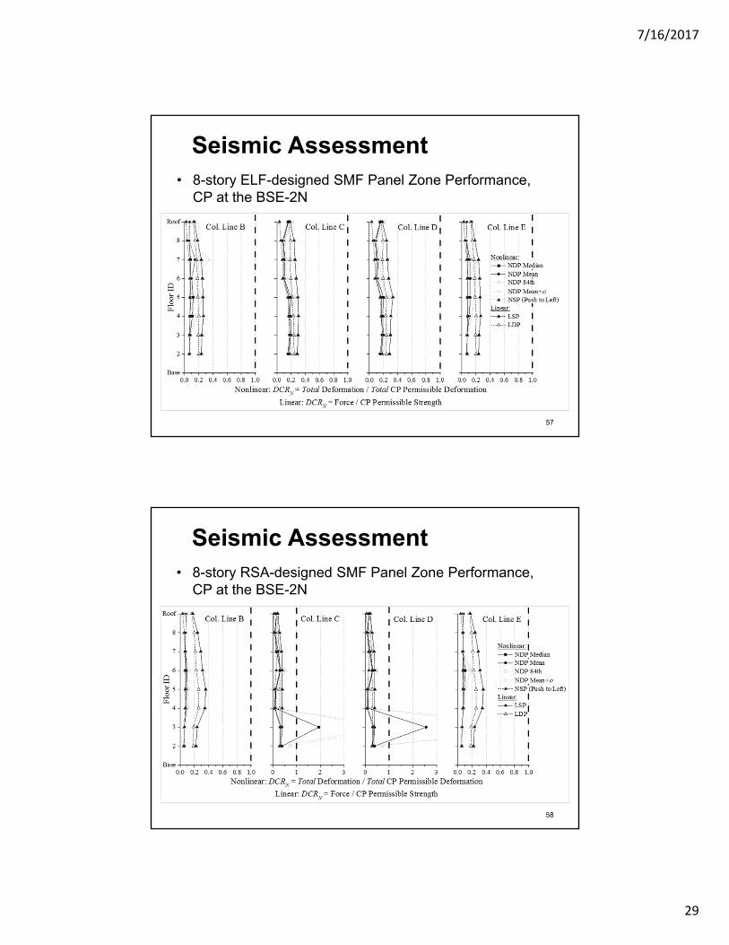
Seismic Assessment• 8-story ELF-designed SMF Panel Zone Performance,
CP at the BSE-2N
57
Seismic Assessment• 8-story RSA-designed SMF Panel Zone Performance,
CP at the BSE-2N
58
7/16/2017
30
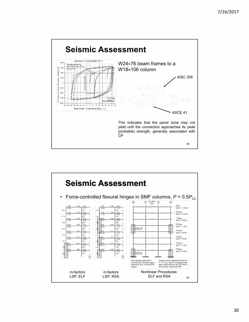
Seismic Assessment
W24×76 beam frames to a W18×106 column
This indicates that the panel zone may notyield until the connection approaches its peak(probable) strength, generally associated withCP
AISC 358
ASCE 41
59
• Force-controlled flexural hinges in SMF columns, P > 0.5PCL
m-factorsLSP: ELF
m-factorsLSP: RSA
Nonlinear Procedures:ELF and RSA 60
Seismic AssessmentSeismic Assessment

7/16/2017
31
Seismic Assessment
• 8-story ELF-designed SMF Column Hinge Performance, CP at the BSE-2N
F.C.F.C.
F.C. = Force-Controlled Column 61
Seismic Assessment
• 8-story RSA-designed SMF Column Hinge Performance, CP at the BSE-2N
62
F.C.F.C.
F.C. = Force-Controlled Column

7/16/2017
32
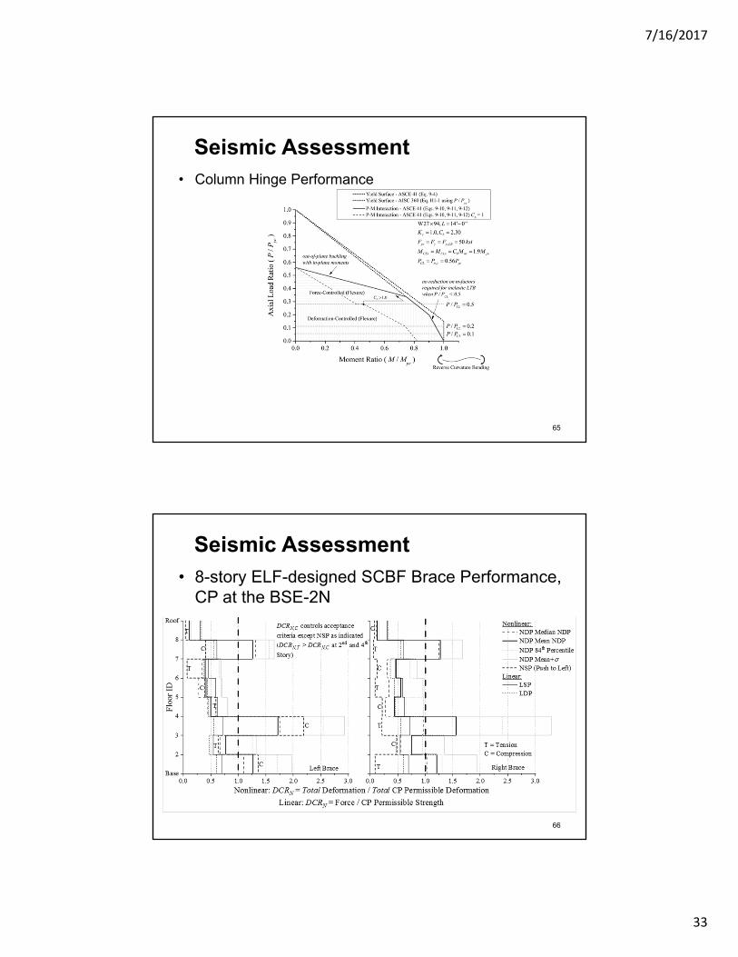
Seismic Assessment
• Column Hinge Performance
– Deformation-Controlled
– Force-Controlled
63
member section
Where did PCL come from?
Seismic Assessment• Column Hinge Performance
64
AISC 360 says ---
7/16/2017
33
Seismic Assessment• Column Hinge Performance
65
Seismic Assessment
• 8-story ELF-designed SCBF Brace Performance, CP at the BSE-2N
66
7/16/2017
34
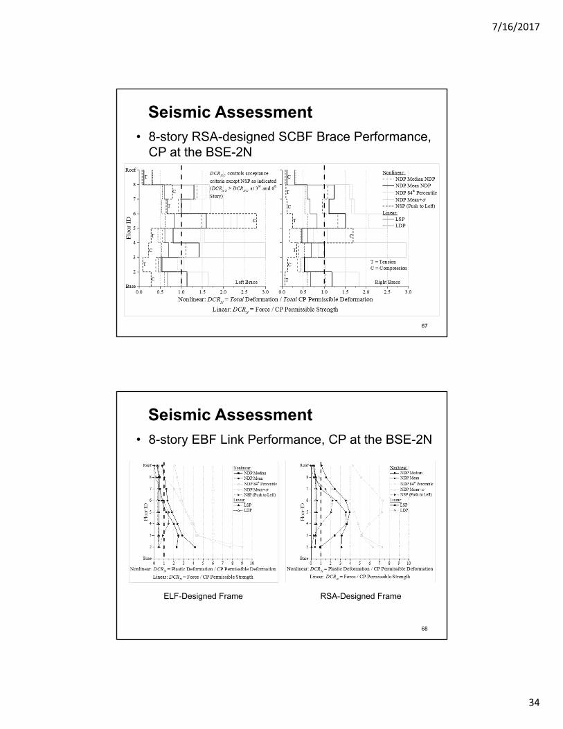
Seismic Assessment
• 8-story RSA-designed SCBF Brace Performance, CP at the BSE-2N
67
Seismic Assessment
• 8-story EBF Link Performance, CP at the BSE-2N
68
ELF-Designed Frame RSA-Designed Frame

7/16/2017
35
Seismic Assessment
• 8-story ELF-designed BRBF Brace Performance, CP at the BSE-2N
69
Seismic Assessment
• 8-story RSA-designed BRBF Brace Performance, CP at the BSE-2N
70
7/16/2017
36
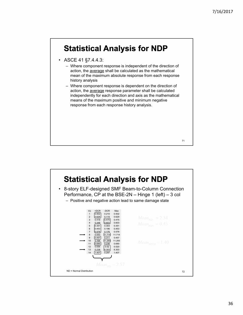
Statistical Analysis for NDPStatistical Analysis for NDP• ASCE 41 §7.4.4.3:
– Where component response is independent of the direction of action, the average shall be calculated as the mathematical mean of the maximum absolute response from each response history analysis
– Where component response is dependent on the direction of action, the average response parameter shall be calculated independently for each direction and axis as the mathematical means of the maximum positive and minimum negative response from each response history analysis.
71
Statistical Analysis for NDPStatistical Analysis for NDP• 8-story ELF-designed SMF Beam-to-Column Connection
Performance, CP at the BSE-2N – Hinge 1 (left) – 3 col– Positive and negative action lead to same damage state
EQ +DCR -DCR Max1 0.502 0.210 0.5022 0.629 0.115 0.6293 0.418 0.475 0.4754 0.348 0.603 0.6035 0.351 0.303 0.3516 0.453 0.196 0.4537 0.578 0.176 0.5788 0.053 11.714 11.7149 0.457 0.311 0.45710 0.164 11.293 11.29311 0.690 0.236 0.69012 0.054 0.52 0.52013 0.238 6.303 6.30314 1.407 0.297 1.407
ND = Normal Distribution 72

7/16/2017
37
Statistical Analysis for NDPStatistical Analysis for NDP• 8-story ELF-designed SCBF Brace Performance, CP at
the BSE-2N – 1st Story (all completed)– Positive and negative action do not lead to same damage state
Left Brace Right BraceEQ T C T C1 0.094 1.134 0.127 1.0262 0.162 1.723 0.087 0.9373 0.139 3.136 0.610 1.0334 0.096 0.752 0.085 0.9835 0.533 0.285 0.528 3.4966 0.271 2.007 0.092 1.8507 0.094 0.818 0.081 0.8818 0.111 1.062 0.095 0.7219 0.091 1.532 0.146 1.107
10 0.073 0.558 0.096 0.45911 0.104 0.748 0.089 1.20612 0.09 1.516 0.092 0.73313 0.125 1.333 0.115 1.18314 0.075 0.897 0.088 1.319
73ND = Normal Distribution, C = Compression, T = Tension, L = Left Brace, R = Right Brace
Statistical Analysis for NDPStatistical Analysis for NDP• 8-story ELF-designed BRBF Brace Performance, CP at
the BSE-2N – 1st Story (all completed)– Positive and negative action lead to possibly same damage state
Left Brace Right BraceEQ T C T C1 0.695 0.32 0.248 0.7772 0.510 0.475 0.391 0.5793 1.043 0.163 0.099 1.1534 0.055 1.298 1.192 0.0925 0.076 1.242 1.133 0.1286 1.291 0.606 0.52 1.3737 2.211 1.02 0.994 2.3048 0.777 0.318 0.248 0.8689 0.455 0.218 0.154 0.54410 0.789 0.11 0.054 0.88911 0.198 0.779 0.692 0.25612 0.683 0.607 0.552 0.7713 2.617 0.416 0.338 2.79514 0.497 1.48 1.393 0.566
74ND = Normal Distribution, C = Compression, T = Tension, L = Left Brace, R = Right Brace
7/16/2017
38
Assessment Conclusions
• Many conclusions and observations are detailed in NIST reports. Too many to discuss here.
• Primary Observations
– Analytical results based on component-level performances indicate that new SFRSs designed in accordance with ASCE 7, and its referenced standards, can have difficulty achieving the ASCE 41 BPON for an existing building intended to be equivalent to a new building. This observation is driven by the performance of specific system components
– Assuming the archetype buildings meet the collapse performance objective of ASCE 7, the results of the assessment procedures indicate that ASCE 41 is generally conservative for steel SFRSs. ASCE 41 analysis would require retrofit or replacement of specific components of a code-compliant SFRS to satisfy the CP BPL, given an MCE event
75
Assessment Conclusions– A significant number of columns, primarily at the base of the
frames, did not satisfy the ASCE 41 acceptance criteria (force-controlled). The results for columns can be enhanced by more mechanistically consistent assessment provisions and analytical modeling parameters for columns
– Results from this study indicate that for ASCE 41 to be used as a seismic design procedure for new steel buildings, as a performance-based alternative to ASCE 7 (see ASCE 7 §1.3.1.3), acceptance criteria for the various analysis methods must be calibrated to each other to consistently result in a uniform collapse risk (e.g., 10% P(collapse) given MCE shaking).
– NIST reports provide comprehensive list of recommend future research
76

7/16/2017
39
Assessment Conclusions• Link between ASCE 7 and ASCE 41
– acceptance criteria for a component in ASCE 41 are not directly calibrated to the seismic performance objective of ASCE 7 (10% probability of partial or total collapse given an MCE event—or 1% probability of partial or total collapse in 50 years).
– equating the two objectives of the standards would imply that only one structural performance level with an associated earthquake hazard level can be coupled: CP at the MCER. However, this would be difficult based on a member-level binary performance solution in ASCE 41. What percentage of components needs to fail the associated CP SPL to achieve a 10% probability of total or partial collapse given an MCER event?
– Current efforts are assessing the archetype buildings using FEMA P695 to ascertain the collapse probability in relation to the ASCE 7 performance objective. Results from this study could be used to probabilistically relate the R-factor in ASCE 7 to the m-factors and inelastic deformations using story drift. 77
Assessment Conclusions• Link between ASCE 7 and ASCE 41
– A consequence of a deterministic-type component evaluation (i.e., pass or fail) is that analytical results, depending on the accuracy of the model and analysis algorithms, can be independent of the behavior of the system. Individual member performance and the potential need to retrofit or replace it are therefore based on an analysis output rather than the influence of the component performance on the system performance.
– ASCE 41 is available now and being used for PBSD of building systems and components. In many cases, the acceptance criteria in ASCE 41 are being used to justify computed seismic performance to buildings officials as being satisfactory. The question is what seismic performance is being justified: the objective defined in ASCE 41 or that intended in ASCE 7?
78

7/16/2017
40
Thank you
Q & A
Thank you
Q & A
79