Embed Size (px)
Citation preview

ASSESSMENT OF DAM SAFETY ISSUES
PARADISE DAM
QUEENSLAND, AUSTRALIA
PROJECT 19-6089
REVISION 0
29 MARCH 2020
SUBMITTED TO:
BUNDABERG FRUIT AND VEGETABLE GROWERS

R1 – 196089/20
ASSESSMENT OF DAM SAFETY ISSUES
PARADISE DAM
QUEENSLAND, AUSTRALIA
PROJECT NO. 19-6089
REVISION 0
29 MARCH 2020
RIZZO INTERNATIONAL, INC.
500 PENN CENTER BOULEVARD
BUILDING 5, SUITE 100
PITTSBURGH, PENNSYLVANIA 15235
TELEPHONE: (412) 856-9700
TELEFAX: (412) 856-9749
WWW.RIZZOINTL.COM
Page 2 of 56

R1 – 196089/20
APPROVALS
Project No.: 19-6089
Report Name: Assessment of Dam Safety Issue Paradise Dam Queensland, Australia
Date: 29 March 2020
Revision No.: 0
Approval by the responsible manager signifies that the document is complete, all required reviews are complete, and the document is released for use.
Originator: 29 March 2020 Paul C. Rizzo Date Chief Technical Officer
Independent
Verifier and 29 March 2020 Project Manager Paul C. Rizzo Date Chief Technical Officer
Page 3 of 56

R1 – 196089/20
CHANGE MANGEMENT RECORD
Project No.: 19-6089
Report Name: Assessment of Dam Safety Issue Paradise Dam Queensland, Australia
REVISION
NO. DATE DESCRIPTIONS OF CHANGES/AFFECTED PAGES
0 29 March 2020 Submittal
Page 4 of 56

R1 – 196089/20
TABLE OF CONTENTS
PAGE
List of Tables and Figures..........................................................................................................6 List of Appendices .....................................................................................................................6 List of Acronyms .......................................................................................................................7 1.0 Introduction and Summary Conclusions ........................................................................8
2.0 Sources of Information ................................................................................................10
2.1. Referral Guidelines and Criteria ......................................................................10
3.0 Sliding Friction and Cohesion .....................................................................................12
3.1. Background ......................................................................................................12
3.2. The Nature of Lift Joints in RCC Dams ..........................................................15
3.3. Leakage Along Lift Joints ................................................................................17
3.4. Bedding Mixes on Lift Joints ...........................................................................19
3.5. Design Considerations for Lift Joints ..............................................................20
3.5.1. Interpretation of Available Shear Strength Data along Lift Joints ....23
3.5.2. Assessment of the Safety Margin along Lift Joints at Paradise ........23
3.6. Special Stability Analysis Requested by the Commission ..............................24
4.0 QA/QC Program ..........................................................................................................26
5.0 Remedial Actions to Improve Sliding Resistance Across Lift Joints ..........................27
5.1. Probabilistic Approach.....................................................................................27
5.2. Apron Fault ......................................................................................................27
5.3. Contract Considerations ...................................................................................28
5.4. Remediation Action to Improve Margin of Safety Across Lift Joints – Main Spillway ...........................................................................................................28
5.4.1. Post-Tensioned Anchors with RCC Dams ........................................29
5.4.2. Inclination of Post-Tensioned Anchors at Bagnell Dam ...................29
5.4.3. Cost of Anchors at Bagnell Dam .......................................................33
6.0 Main Spillway Apron and Stilling Basin .....................................................................34
6.1. Comments on the Existing Spillway Features and Remedial Actions .............34
6.2. Hydraulic Modeling .........................................................................................35
6.3. Recommendations for Remediation of the Paradise Dam Spillway ................36
6.3.1. Main Spillway Geometry ..................................................................36
7.0 Basic Conclusions ........................................................................................................38
Page 5 of 56

R1 – 196089/20
LIST OF TABLES AND FIGURES
TABLE NO. TITLE PAGE
Table 3-1 RCC versus Conventional Concrete (CVC) ...................................................14
FIGURE NO. TITLE PAGE
Figure 3-1 Typical Gravity Dam ......................................................................................12
Figure 3-2 RCC Transport by Earthmoving Trucks .........................................................13
Figure 3-3 Spreading RCC into 300 mm Horizontal Lifts ...............................................13
Figure 3-4 Compacting RCC with Larger Rollers ............................................................14
Figure 3-5 Horizontal Lift Joints in RCC Dams ...............................................................15
Figure 3-6 Lift Joints in a Prototype Test Section at Saluda Dam Cut with a Diamond Wire Saw ........................................................................................................16
Figure 3-7 Core Extracted from Paradise Dam to Examine Lift Joints ............................17
Figure 3-8 Conventional Concrete Barrier on the ............................................................18
Figure 3-9 Taum Sauk Dam (Monolith No. 7) Under Construction ................................19
Figure 3-10 Prototype Test Section for Taum Sauk Dam .................................................20
Figure 3-11 Shear Strength Terminology ...........................................................................21
Figure 5-1 Bagnell Dam, Missouri, USA .........................................................................30
Figure 5-2 Anchor Head and Corrosion Protection at Bagnell Dam ................................32
Figure 6-1 Conceptual Remediation Works – Main Spillway ..........................................36
LIST OF APPENDICES
Appendix A Letter Report – Recommended Testing Program ...........................................39
Appendix B List of Documents Requested from SunWater ...............................................47
Appendix C Friction Angle Analysis ..................................................................................53
Page 6 of 56

R1 – 196089/20
LIST OF ACRONYMNS AND ABBREVIATIONS
AEP Annual Exceedance Probability
AHD Australian height datum
ANCOLD Australian National Committee on Large Dams
BFVG Bundaberg Fruit and Vegetable Grower
CFD Computational Fluid Dynamics
CVC Conventional Concrete
EPRI Electric Power Research Institute
FERC Federal Energy Regulatory Commission
FoS Factor of Safety
HDPE High Density Polyethylene
ICOLD International Committee on Large Dams
JRC Joint Roughness Coefficient
kN/m3 Kilonewton Per Cubic Meter
m meters
mm millimeters
MPa Megapascal
PAR Population at Risk
PDIP Paradise Dam Improvement Project
PMF Probable Maximum Flood
PTI Post-Tensioning Institute
QA/QC Quality Assurance/Quality Control
RCC Roller Compacted Concrete
RIZZO RIZZO International, Inc.
SunWater SunWater Limited
TRP Technical Review Panel
USACE United States Army Corps of Engineers
Page 7 of 56

R1 – 196089/20
1.0 INTRODUCTION AND SUMMARY CONCLUSIONS
Paradise Dam in northeast Queensland was completed in 2005 as one of the first roller-compacted concrete (RCC) dams in Australia. Originally constructed by the Burnett Dam Alliance for Burnett Water, it is now owned and operated as a water supply dam by SunWater Limited (SunWater). Bundaberg Fruit and Vegetable Growers association (BFVG), based in Bundaberg, QLD, is a major offtake user for irrigation.
SunWater has raised concerns about the safety of Paradise Dam specifically as it relates to the behavior of the RCC comprising Paradise Dam, as well as concern for the performance of the Main Spillway Apron and Stilling Basin. SunWater is currently contemplating a Dam Improvement Program that includes, among several options, lowering the level of the impounded Reservoir to increase dam safety by reducing the head (pressure) on the upstream face of the Dam. BFVG is concerned that lowering the Reservoir, even temporarily during a remediation program, could be a major impact on the present and future capacity of the Reservoir to satisfy the increasing demand for irrigation water and therefore the future of the Bundaberg Region’s agricultural industry. The estimated Population at Risk (PAR) downstream of the Dam based on a 2019 Failure Impact Assessment Report prepared by SunWater is 8,830 (1 in 200 AEP Event) . BFVG, many of whom live downstream as part of the PAR has requested RIZZO International, Inc. (RIZZO) to give an unbiased and independent opinion of the risk associated with any inadequacies of Paradise Dam.
BFVG has retained RIZZO to inquire into the safety of Paradise Dam as impacted by the alleged inadequacy of the RCC Lift Joints and the Main Spillway. RIZZO has investigated the alleged inadequacy of the RCC and its impact on the safety of the Dam, specifically the ability of the RCC to resist sliding along RCC Lift Joints and sliding along the interface of the RCC and the foundation rock at the base of the Dam. Guidelines published by the Australian National Committee on Large Dams (ANCOLD, 2013) were used as a supporting document. We have not investigated the Main Spillway per se, but have reviewed work published by SunWater and their consulting engineer, GHD, and we offer our views on the Spillway system as a whole.
To the degree that remediation is required to improve the resistance to sliding along Lift Joints, we have also conceptually considered the potential synergistic effects of various forms of remediation at the Main Spillway Apron and Stilling Basin.
It should be noted that during our work, we determined that the test data available for assessing the properties of the as-constructed RCC are inadequate. Therefore, on 19 February 2020, under separate cover, RIZZO recommended a new testing program. This
Page 8 of 56

R1 – 196089/20
included our recommendations for a sampling and testing program for the RCC that uses the most modern techniques and experience available for determining the proper parameters required for defendable sliding/stability analyses. This referenced Letter Report is included as Appendix A.
The basic conclusions of our inquiry are briefly summarized as follows:
1. Paradise Dam is in a distressed state, but is highly unlikely to experience a catastrophic failure resulting in the loss of life. The distressed state can be remediated at a reasonable cost as accomplished at other dams around the world, without negative consequences or extreme actions. Remediation is recommended to at least meet current ANCOLD Guidelines concerning factors of safety (FoS) against sliding stability analysis and to prevent severe erosion and scour of the type that occurred in 2013.
2. We did not perform a forensic investigation, but we did observe that the distressed state is associated with the condition of the RCC at the horizontal Lift Joints, largely because the Quality Control/Quality Assurance (QA/QC) Program was not tied to and directly responsive to the design of the Dam.
3. Allegations of inadequate construction practices as compared to current industry practice have merit, but are unproven and, at worst, a contributory cause of the RCC Lift Joint inadequacy.
4. Our assessment of the matter of sliding along Lift Joints is that FoS against sliding at all Lift Joints considered for the defined loading conditions is at least 1.1. We are of the opinion that an alarmist atmosphere has evolved over the safety of Paradise Dam without adequate basis. Indeed, the FoS for the stated conditions is not ideal and the distress should be addressed with suitable corrective engineering actions, but such actions should be measured, not extreme or dramatically disruptive.
5. Remediation to improve the margin of safety against sliding along Lift Joints should be considered jointly with remediation of the Main Spillway Apron and Stilling Basin to capture the benefits of the synergistic effects of the two efforts. With the modifications to the SunWater concept as recommended herein, it may be possible to achieve adequate FoS against sliding without post-tensioned anchors, i.e., simply by modifying the Main Spillway in a certain manner to prevent severe erosion and scour.
Page 9 of 56

R1 – 196089/20
2.0 SOURCES OF INFORMATION
This Report was developed from the sources of information listed below:
1. GHD Memorandum “Review of RCC shear strengths” dated 5 September 2019; and
2. GHD Memorandum “Dam stability analyses dated 5 September 2019”.
3. Paradise Dam - Shear Strength Evaluation Comments – Report by Tatro Hinds dated November 25, 2019
4. Paradise Dam Improvement Project (PDIP) – Overview Report (undated)
5. SunWater Limited, Paradise Dam Safety Improvement Project, Technical Review Panel Report No 2. Dated September 23, 2019
6. Witness Statements and verbal testimony by Dr. Ernest Schrader, Steve Tatro, Michael Marley, Timothy Dolan, Richard Herweynen, Mark Hamilton, Robert Montalvo as given at hearings before the Paradise Dam Commission
7. Various documents available to the public on the Internet
RIZZO also requested formal copies of the documents listed in Appendix B from SunWater; however, SunWater could not respond to this request. SunWater did make available access to an electronic data room where we reviewed certain documents over the internet, but we were not permitted to make copies. In addition to the inconvenience of not being permitted to make copies, we could not find copies of as-built drawings or a detailed construction completion report.
2.1. REFERRAL GUIDELINES AND CRITERIA
Guidelines and criteria for assessing the safety of gravity dams that have been developed by the profession and regulators are applicable to Paradise Dam and have been considered in this assessment. The dominant guideline is the ANCOLD Guidelines on Design Criteria for Concrete Gravity Dams, as published in September 2013, well after Paradise Dam was designed and constructed. ANCOLD Guidelines in place at the time of the design were published in 1991, but these did not include much information about RCC Dams. Section 10 of the 2013 ANCOLD Guidelines is dedicated to RCC Dams and was used in this assessment.
Major guidance is also available in the Federal Energy Regulatory Commission (FERC, 2002) Engineering Guidelines for the Evaluation of Hydropower Projects, specifically
Page 10 of 56

R1 – 196089/20
Chapter 3, which is dedicated to Gravity Dams. RIZZO used this guidance in addition to the ANCOLD Guidance throughout this assessment.
Other referral guidelines and criteria are available in several United States Army Corps of Engineers (USACE) manuals, Guidelines from the Canadian Dam Association (2007), the International Committee on Large Dams (ICOLD) (2009), and work by Professor Fell in Chapter 10 of the text Geotechnical Engineering of Dams. Finally, we have also used our own internal practice guidelines in this assessment, especially as related to RCC Dams.
A significant issue in our professional practice is to ignore cohesion in the assessment of sliding stability across Lift Joints in RCC dams. This practice has influenced our thinking as regards Paradise Dam. Cohesion was credited by the original designer as a contributor to sliding resistance in the original design for Paradise, whereas we contend that this should not have been done.
Page 11 of 56

R1 – 196089/20
3.0 SLIDING FRICTION AND COHESION
3.1. BACKGROUND
Paradise Dam was designed as a typical concrete gravity dam whereby the weight of the dam and friction between the base of the dam and the underlying rock are used to resist the water pressure acting on the upstream face, as illustrated on Figure 3-1. The zone between the basal layer of concrete and the underlying rock is often called the interface. When the dam body also serves as an overflow Spillway, the downstream toe of the dam normally includes an Apron to protect against erosion of the rock at the toe.
FIGURE 3-1
TYPICAL GRAVITY DAM
The Main Spillway at Paradise Dam is similar to the typical gravity dam illustrated on Figure
3-1 including the Apron, but with an extension downstream referred to as a Stilling Basin to “still” the turbulent water flowing over the Spillway.
In the case of Paradise Dam, the concrete is a special form of concrete called Roller Compacted Concrete, abbreviated as RCC. RCC was originally developed over 50 years ago and has advanced through the 1970’s and 80’s. It is placed with large earth-moving trucks or conveyors, spread with bulldozers, and compacted with large rollers, hence the name, as illustrated in the photos in Figures 3-2, 3-3 and 3-4.
Interface between concrete and rock
Page 12 of 56

R1 – 196089/20
FIGURE 3-2
RCC TRANSPORT BY EARTHMOVING TRUCKS
FIGURE 3-3
SPREADING RCC INTO 300 MM HORIZONTAL LIFTS
Page 13 of 56

R1 – 196089/20
FIGURE 3-4
COMPACTING RCC WITH LARGER ROLLERS
Table 3-1 outlines the major differences between RCC and Conventional Concrete, often termed as CVC. This table clearly shows that RCC is “special” and depends a great deal on experience; one cannot, a priori and simply adopt all of the principles of CVC when designing and constructing with RCC.
TABLE 3-1
RCC VERSUS CONVENTIONAL CONCRETE (CVC)
RCC CONVENTIONAL CONCRETE
Placed in Horizontal Layers – 300 mm Usually Placed in Vertical Monoliths with no dimension greater than 2 m
Mix usually includes 50 % to 70% pozzolans as replacement to cement. Pozzolans include flyash, slag, volcanic materials.
Pozzolans are generally minimized, less than 15%
Rapid placement rates require greater temperature control with pozzolans, ice, aggregate cooling
Placement rates are slower than with RCC
Workability is controlled with Vebe measurements, slump measurements and additives
Workability is controlled with water content and slump measurements, sometimes with additives
Strength – same as CVC but achieved at 180 to 365 days Same as RCC but achieved in 28 days
Temperature testing of RCC design mix generally required- both adiabatic and thermal conductivity
Temperature testing generally not required
Page 14 of 56

R1 – 196089/20
RCC CONVENTIONAL CONCRETE Thermal analysis generally required to set size of monoliths and rate of placement
Thermal analysis generally not required if codes are applied
Slump – Very low slump, often near “0” to allow for movement of trucks and equipment Slump generally in the range of 4 to 8 inches
Cost – generally lower than CVC, often ⅓ of the cost of CVC Cost generally higher than RCC
Rate of Construction is much faster than RCC
Rate of construction slower than RCC
QA/QC – more diligent program required than for CVC
Standard QA/QC programs apply
Design very dependent on experience Design based on very detailed and long standing codes
Prototype Test Program required for medium and larger size dams before actual construction
Prototype test programs generally not required
Craft Labor requires training with a prototype test program before construction begins
Craft Labor generally experienced with CVC procedures
3.2. THE NATURE OF LIFT JOINTS IN RCC DAMS
RCC is placed in dams as horizontal 300 mm thick lifts, as illustrated in Figure 3-5 with the interface zones between lifts called Lift Joints. Each Lift is compacted, generally with a large roller of the type illustrated on Figure 3-4, then the next Lift is placed, and the process repeated.
FIGURE 3-5
HORIZONTAL LIFT JOINTS IN RCC DAMS
Smaller rollers are used on the edges next to forms or penetrations such as galleries or penstocks. Some more modern RCC placements are not horizontal, utilizing a methodology called the Slope Layer Method. RCC at Paradise Dam was placed compacted with horizontal 300 mm layers. Incidentally, it has been shown that the depth of penetration reached by a
Page 15 of 56

R1 – 196089/20
large roller is about 1.5 times the diameter of the main roller, or generally about one meter; consequently, a pass of a normal roller is likely to be effective across two, possibly three Lift Joints.
Figure 3-6 is a photo illustrating the nature of as-built Lift Joints where the dark lines show the actual Joint where discernable. This photo was taken of a prototype test section for the Saluda Dam in the USA that has been cut with a horizontal diamond wire cutter to allow inspection of the contractor’s ability to cope with Lift Joints. This was done as part of the QA/QC program for the Saluda Dam project.
FIGURE 3-6
LIFT JOINTS IN A PROTOTYPE TEST SECTION AT SALUDA DAM CUT WITH
A DIAMOND WIRE SAW
An alternate means of understanding Lift Joints after construction is to drill a vertical core boring down through the dam (or prototype test section) and examine the quality of the core across the Lift Joints. Figure 3-7 illustrates the nature of some of the Lift Joints as observable in core extracted from Paradise Dam.
Lift Joints
Page 16 of 56

R1 – 196089/20
FIGURE 3-7
CORE EXTRACTED FROM PARADISE DAM TO EXAMINE LIFT JOINTS
The Lift Joints pointed out in Figure 3-7 are mostly broken as compared to those pointed out in the prototype test section in Figure 3-6. While one might hope to see unbroken core across Lift Joints, it is difficult to achieve as it is very much dependent on the drilling equipment and driller’s skills. Nevertheless, the Lift Joints at Paradise Dam are distressed for several reasons, but primarily because of the type of mix of the RCC and the elapsed time between RCC placement and compaction. This lack of confidence in the quality of the Lift Joints at Paradise Dam has led SunWater and other local professionals to question of stability of the Dam in regards to sliding across the Lift Joints and to some degree, the resistance to sliding at the interface between the base of the Dam and the foundation rock.
3.3. LEAKAGE ALONG LIFT JOINTS
As suggested by Figure 3-5, Lift Joints might serve as a direct path for leakage through the dam from the upstream face to the downstream face unless some form of counter measure is taken. Some form of low permeability barrier is generally included on the upstream face of RCC dams, the RCC is enhanced with additional cement, such as in Grout Enriched RCC, or the Lift Joints are enhanced with additional cement with a bedding mix that is designed to ensure a tight, relatively impervious Lift Joint. Figure 3-8 illustrates a low permeability zone of CVC on the upstream face at Taum Sauk Dam in the USA constructed in between 2005 and 2009. Bedding mix was also used at Taum Sauk as a form of “belt and suspenders” approach to minimize leakage through Lift Joints. Incidentally, both Saluda Dam and Taum Sauk Dam were designed and managed by RIZZO.
Lift Joints
Lift Joints
Page 17 of 56

R1 – 196089/20
FIGURE 3-8
CONVENTIONAL CONCRETE BARRIER ON THE
UPSTREAM FACE AT TAUM SAUK DAM
At Paradise Dam, the designers chose to install an impervious geosynthetic liner, often called a Carpi Liner, named after the primary supplier of such liners across the world. While Carpi liners have their own issues, RIZZO has no argument with this approach. The evidence of the effectiveness of the Carpi Liner is that there is no seepage or calcite precipitate observable on the downstream face of the Main Spillway.
Figure 3-9 as well as the photo in Figure 3-10 show that a gallery with crest-to-gallery drains was installed at Taum Sauk, as is the case with all RCC dams designed by RIZZO. Neither was provided at Paradise Dam, a deficiency that might be attributed to the practice at the time. On the other hand, we note that contractors do not like galleries or crest-to-gallery drains as they impede progress in RCC placement and in the case of design-build arrangements, designers are usually pushed to eliminate both galleries and crest-to-gallery drains. We have no evidence that this was the case at Paradise Dam.
Page 18 of 56

R1 – 196089/20
FIGURE 3-9
TAUM SAUK DAM (MONOLITH NO. 7) UNDER CONSTRUCTION
3.4. BEDDING MIXES ON LIFT JOINTS
The design of RCC dams often calls for a bedding mix to be applied to a portion or the entire Lift Joint surface before the subsequent lift of RCC is placed. The purpose of the bedding mix is generally to address one or several of the following:
• Reduce the leakage along the Lift Joint between the upstream face and crest-to-gallery drains if specified.
• Increase the shear resistance to sliding along the Lift Joint.
• Ensure bonding between Lifts of RCC if the Lift Joint is “cold,” meaning the lower Lift of RCC has begun to set up and therefore will not adequately bond to the new Lift being placed on top.
• Act as a remedial measure if the Lift Joint is inadequate for any of number of reasons, such as segregation, uncontrolled excessive heat of hydration, poor cleaning, rain or freezing, damage by equipment, etc.
The bedding mix generally has higher strength than the parent RCC and may take the form of a mortar consisting only of sand and cement. Alternatively, it may include a coarse sand and gravel, particularly if increased shear strength is necessary. The bedding mix generally has a thickness around 10 mm and is placed by hand spreading or with small equipment.
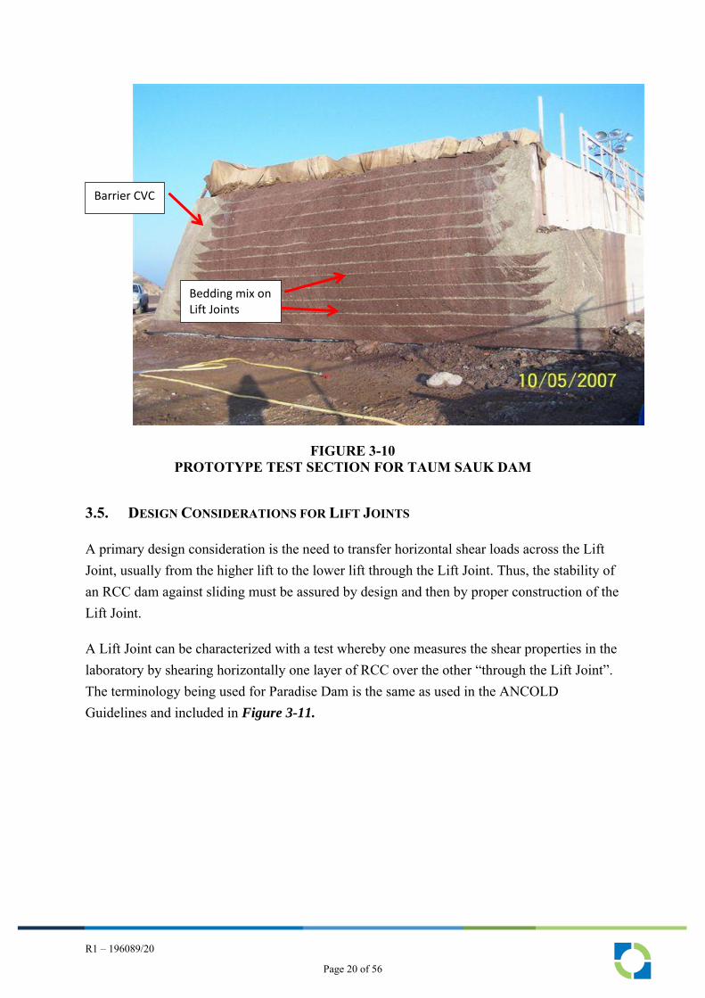
Figure 3-10 illustrates the bedding mix placed in the prototype test section at Taum Sauk between the brown-colored RCC Lifts (the brown color is associated with the iron rich aggregate).
Gallery
CVC Barrier
Page 19 of 56
R1 – 196089/20
FIGURE 3-10
PROTOTYPE TEST SECTION FOR TAUM SAUK DAM
3.5. DESIGN CONSIDERATIONS FOR LIFT JOINTS
A primary design consideration is the need to transfer horizontal shear loads across the Lift Joint, usually from the higher lift to the lower lift through the Lift Joint. Thus, the stability of an RCC dam against sliding must be assured by design and then by proper construction of the Lift Joint.
A Lift Joint can be characterized with a test whereby one measures the shear properties in the laboratory by shearing horizontally one layer of RCC over the other “through the Lift Joint”. The terminology being used for Paradise Dam is the same as used in the ANCOLD Guidelines and included in Figure 3-11.
Bedding mix on Lift Joints
Barrier CVC
Page 20 of 56

R1 – 196089/20
FIGURE 3-11
SHEAR STRENGTH TERMINOLOGY
The key terms of interest here are shown on the lower half of Figure 3-11 as cohesion and , the friction angle. The upper half of Figure 3-11 is a plot of the horizontal displacement of the upper half of a specimen (the upper RCC Lift) relative to the lower half of a specimen (the lower RCC Lift). One can observe a peak shear strength and a residual shear strength. In the lower half of Figure 3-11, one can see a plot of the peak strength and the residual strength. A Lift Joint behaves in the same manner. During the initial loading, a peak strength is realized but after the peak strength is achieved, the shear strength reverts down to a residual strength which is defined with a residual angle with no cohesion intercept on the ordinate axis.
Page 21 of 56

R1 – 196089/20
Based on such tests, the designer choses a angle and some designers add a cohesion such that the resistance to sliding is characterized as the normal stress acting on the lower lift of RCC, usually called N minus any water pressure that may exist in the Lift Joint, multiplied by the tangent of the friction angle which can be described mathematically as
= (N – u) x Tan (−)
Some designers take credit for cohesion along a Lift Joint and use the following equation
= (N – u) x Tan + C (−)
Where = shear strength N = Normal Pressure (or weight) u = water pressure in the Lift Joint Tan = Tangent of the friction angle C = Cohesion
It is clear from these two equations that the shear strength can be much higher across a Lift Joint if cohesion exists. But if it is not present, the resistance to sliding is frictional only and dependent on the friction angle.
ANCOLD provides guidance on how to use these equations for evaluating the stability of a dam, and particularly across a Lift Joint in Table 6.1 of the ANCOLD Guidelines on Design Criteria for Concrete Gravity Dams reproduced below.
TABLE 3-2 RECOMMENDED MINIMUM FACTORS OF SAFETY AGAINST
SLIDING (REPRODUCED FROM ANCOLD, 2013)
SCENARIO LOAD CASE
USUAL UNUSUAL EXTREME
Peak Strength – c’ and f’ ‘not well defined’1,5 3.03 2.03 1.53
Peak Strength – c’ and f’ ‘well-defined’1,5 2.03 1.53 1.33
Residual Strength c’ and f’ ‘ well-defined’1,5,8
(refer to Section 5.1, particularly Figure 5.1) 1.52,9 1.32,9 1.12,9
1. “Well-defined means a sufficient number of tests have been done on concrete core from the dam and lift surfaces to give the strength parameters with reasonable certainty …..
2. For these lower FoS to apply the residual strength c’ would normally be expected to be zero. It is common practice to assume c’= 0 and f’ = 45o for residual strength of concrete. This is consistent with Electric Power Research
Page 22 of 56

R1 – 196089/20
Institute (EPRI, 1992) data which has 90% of samples with a strength > c’=0, ’ = 48o for the sliding shear strength (peak strength of unbonded specimens……..
3.5.1. Interpretation of Available Shear Strength Data along Lift Joints
RIZZO has developed a professional opinion regarding the appropriate shear strength that should be used for assessing sliding resistance along Lift Joints at Paradise Dam. The data set is problematic because of the quality of the sampling and testing details; however, “some data are better than no data regardless of quality”. We have already recommended a new project-specific test program as stated in Section 1.0 and included in Appendix A.
Our professional opinion has considered the following information sources:
• The raw data available from shear strength tests measured in several test programs on core samples over the years,
• Data and information from the QA/QC Program as addressed in Section
4.0
• Data interpretation by Steve Tatro in the Tatro Hinds Report dated 25 November 2019
• Witness statements by Timothy Dolan and Dr. Ernest Schrader
• GHD Memorandum “Review of RCC shear strengths” dated 5 September 2019
• My site visit in early 2020 when I observed the RCC Lift Joints exposed on the secondary Spillway
At the present and for purpose of considering corrective actions, it is our opinion that the resistance to sliding across a Lift Joint at Paradise Dam should consider C = 0 and = 40o.
3.5.2. Assessment of the Safety Margin along Lift Joints at Paradise
We have considered the margin of safety against sliding along Lift Joints at Paradise Dam using the proven practice followed in our firm. In general, our practice is the following:
• We conduct a Gravity Dam Stability Analysis with a Mathcad package that is fully consistent with Appendix B of the ANCOLD Guidelines (2013). For Paradise Dam, we also ran a hand calculation with Appendix B against our Mathcad application using Paradise Dam parameters as a check on this statement.
• We use cohesion equal 0 (C = 0) with a suitable friction angle, in regard to strength parameters. For this Assessment, we used = 40o as discussed in Section 3.5.1.
Page 23 of 56

R1 – 196089/20
• For the uplift pressure acting at the heel, we account for a geosynthetic liner on the upstream face by using a 50% reduction of the head water, as long as there is adequate tie-in to a plinth or into rock. This is based on our experience through piezometric measurements at other dams.
• For other types of barriers, such as CVC or grout-enriched RCC, we use the full head, taking into account grout curtains and a gallery with drains if applicable.
• For uplift pressure acting at toe, our practice is to use the tailwater pressure acting at the toe of the dam, not at an Apron or extension, unless piezometric data indicate otherwise. At Paradise Dam, we use full tailwater at the toe.
• We check sliding at the lowermost base of the Dam, at the lowermost Lift Joint and at Lift Joints at ⅓ height and ⅔ height. If there is a discernable trend in the results for Lift Joints above the lower most, we perform more detailed checks at other Lift Joints.
• Unless dictated otherwise by local regulations, we use the FERC Guidelines for Factors of Safety.
The result of our assessment is that the FoS against sliding at all Lift Joints considered for the defined loading conditions is at least 1.1. We are of the opinion that an alarmist atmosphere has evolved over the safety of Paradise Dam as regards the Lift Joints without adequate basis. Indeed, the FoS for the stated conditions is not ideal and the distress should be addressed with suitable corrective engineering actions, but such actions should be measured, not extreme or dramatically disruptive.
3.6. SPECIAL STABILITY ANALYSIS REQUESTED BY THE COMMISSION
During the Paradise Dam Commission hearings in March 2020, the Commission asked if some of the experts, specifically Schrader and RIZZO, could perform and report on a special, limited stability analysis of Monolith H of the Main Spillway. The Commission set all of the pertinent parameters to be used by the experts to, presumably, check the repeatability of the analysis and variability of the results among the experts.
The parameters established by the Commission are as follows:
1. Sliding failure is considered along a horizontal Lift Joint at RL 32.4 m at Monolith H.
2. The behavior of the Lift Joint is purely frictional, i.e., cohesion should be ignored.
3. The unit weight of the RCC is 24.17 kN/m3
4. The unit weight of water is 9.81 kN/m3
Page 24 of 56

R1 – 196089/20
5. The unit weight of sediment is 18.0 kN/m3
6. The top of the sediment in the Reservoir is at RL 38.0 m, i.e., the height of the sediment above the sliding plane is 5.6 m = 38.0-32.4 m.
7. Only 80% of the depth of tailwater is effective in providing stability against sliding.
8. The maximum uplift pressure at the heel of the dam is (a) 50% and (b) 70% of the maximum headwater pressure.
9. The full tailwater pressure acts in uplift at the toe of the dam (not at the downstream end of the Apron).
10. Headwater level – RL 88.6m AHD Tailwater level – RL 80.0m AHD.
The Commission asked us to offer an opinion as to the value of the required friction angle (no cohesion) that would be required for a FoS against sliding equal to unity for the specific set of parameters listed above. The analysis was quite limited but yielded very interesting and highly informative results as documented in RIZZO’s Letter Report dated 17 March 2020, which is included in this document as Appendix C. The results are summarized as follows:
• For a FoS = 1,0 with the uplift pressure at the heel equal to 50% of the headwater, = 43.7o
• For a FoS = 1.0 with the uplift pressure at the heel equal to 70% of the headwater, = 50.8o
GHD interpreted the available friction angle () to be in the range of 39o, and therefore, for the case of the extreme event (AEP = 1/33000 years) considered by the Commission, distress in the form of movement along certain Lift Joints would occur. As an important contrast, the RIZZO results indicate that an event having a recurrence interval on the order of 1000 years would have to occur before major distress will occur. Consequently, RIZZO believes that an alarmist atmosphere has evolved over the safety of Paradise Dam. Indeed, the distress should be addressed with suitable corrective engineering actions, but such actions should be measured, not extreme or dramatically disruptive.
Page 25 of 56

R1 – 196089/20
4.0 QA/QC PROGRAM
The Paradise Dam Project team implemented a Quality Assurance/Quality Control Program including the development of a manual and two technicians dedicated to the effort. The Program included a Lift Joint Quality Index Assessment task developed by Dr. Schrader, plus RCC temperature measurements, RCC density measurements, RCC cylinder strength measurements, slump measurements for flowability, Vebe measurements for workability – all generally consistent with conventional practice.
RIZZO does not use the Lift Joint Quality Index as we discovered very early that it is not a substitute for methodical training and diligence of the technicians, but leads to “average” quality (0 on the scale) and not high quality. We do emphasize and use a Joint Maturity Index to assess whether the joint is “hot”, “warm”, or “cold”, but we strongly emphasize eliminating cold joints by detailed planning of RCC mixing at the plant and delivery. No or minimal time is allowed to pass between delivery and compaction.
There was considerable discussion during the Paradise Dam Commission hearings regarding whether adequate density was achieved at the bottom of the 300 mm lift of RCC on the Lift Joint. RIZZO could find little or no firm density test data to support this contention even though a double probe nuclear densometer was used for most of the placements during construction.
Our review and inquiry into the QA/QC Program concluded that while an acceptable program was implemented, there was little or no connection or tie to the design of the Dam. In our practice, there is a weekly meeting between the QA/QC technicians and the designers to compare the results being achieved in the field as measured by the technicians with the intent and design parameters considered by the designers. There was no evidence of a firm connection or disciplined communication path between the QA/QC technicians and the designers on what was being constructed versus what had been designed. There was a form that was filled out and initialed by the technicians; however, there was no evidence that the designers looked at the form or acknowledged its existence, let alone value. This apparent lack of formalized communication between the QA/QC technicians and the designers, particularly with respect to the number and frequency of cold joints, was a primary fallacy that resulted in distressed Lift Joints on the Dam—distressed as compared to the intent of the design.
Page 26 of 56

R1 – 196089/20
5.0 REMEDIAL ACTIONS TO IMPROVE SLIDING RESISTANCE
ACROSS LIFT JOINTS
The purpose of this section is to address potential remediation actions to improve the safety of Paradise Dam as it is impacted by the deficient margin of safety against sliding in shear over Lift Joints, including sliding along the interface zone between the base of the Dam and the foundation rock.
While this deficiency plus the deficiencies associated with the Main Spillway features, GHD and SunWater have also highlighted the need to address the Secondary Spillway, the right abutment, and the left abutment. We do not disagree with SunWater or GHD in this regard; however, the deficiencies associated with the Main Spillway features and the Lift Joints should be the primary focus within the decade. Indeed the risk analyses reported by SunWater and GHD indicate that about 87 percent of the total risk to the Population at Risk is associated with the Lift Joints and the Main Spillway.
Before discussing our recommended approach for remediation actions to improve Lift Joints, we comment in the following sub-section are several related topics.
5.1. PROBABILISTIC APPROACH
GHD and SunWater have performed major analysis of options for improving dam safety at Paradise with much of the work being at the State of the Practice. RIZZO cautions against relying heavily on the actual probability values quoted for various scenarios, as the profession simply does not know enough about the behavior of dams to quote probability values to two decimal places. The results of probabilistic analysis are more suitable for providing a relative benefit of remediation or a certain type or program, but we advise against using such analysis to communicate the probability of failure or loss of life to the populous. It could be highly misleading and portray a level of confidence or lack thereof in a remediation effort that is undeserving.
5.2. APRON FAULT
The documents made available by SunWater indicate that the Apron Fault was not adequately investigated during the original geotechnical/geological investigation of the Dam. In addition, a “new” group of features named Deryk’s Faults was discovered in 2013 immediately downstream of the Dam. We find it highly disturbing that such dominant features in an area of mapped faults was not thoroughly investigated. We suspect that if the extent of the Apron Fault was known at the early stages of the Project, the axis of the Dam
Page 27 of 56
R1 – 196089/20
would have been (or should have been) moved to avoid this feature. The lack of a thorough investigation of this feature is an unexplained deficiency of the work in our view. These features should be thoroughly understood before beginning remediation work at the Main Spillway.
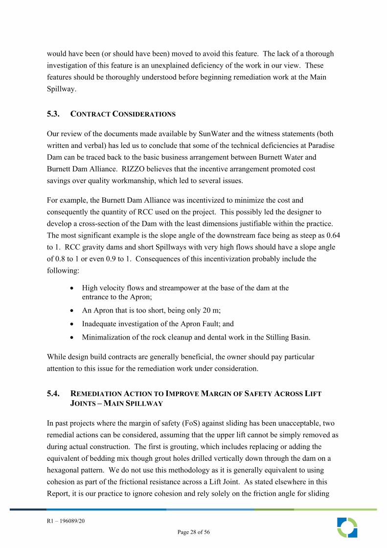
5.3. CONTRACT CONSIDERATIONS
Our review of the documents made available by SunWater and the witness statements (both written and verbal) has led us to conclude that some of the technical deficiencies at Paradise Dam can be traced back to the basic business arrangement between Burnett Water and Burnett Dam Alliance. RIZZO believes that the incentive arrangement promoted cost savings over quality workmanship, which led to several issues.
For example, the Burnett Dam Alliance was incentivized to minimize the cost and consequently the quantity of RCC used on the project. This possibly led the designer to develop a cross-section of the Dam with the least dimensions justifiable within the practice. The most significant example is the slope angle of the downstream face being as steep as 0.64 to 1. RCC gravity dams and short Spillways with very high flows should have a slope angle of 0.8 to 1 or even 0.9 to 1. Consequences of this incentivization probably include the following:
• High velocity flows and streampower at the base of the dam at the entrance to the Apron;
• An Apron that is too short, being only 20 m;
• Inadequate investigation of the Apron Fault; and
• Minimalization of the rock cleanup and dental work in the Stilling Basin.
While design build contracts are generally beneficial, the owner should pay particular attention to this issue for the remediation work under consideration.
5.4. REMEDIATION ACTION TO IMPROVE MARGIN OF SAFETY ACROSS LIFT
JOINTS – MAIN SPILLWAY
In past projects where the margin of safety (FoS) against sliding has been unacceptable, two remedial actions can be considered, assuming that the upper lift cannot be simply removed as during actual construction. The first is grouting, which includes replacing or adding the equivalent of bedding mix though grout holes drilled vertically down through the dam on a hexagonal pattern. We do not use this methodology as it is generally equivalent to using cohesion as part of the frictional resistance across a Lift Joint. As stated elsewhere in this Report, it is our practice to ignore cohesion and rely solely on the friction angle for sliding
Page 28 of 56

R1 – 196089/20
resistance. As a major increase in the friction angle does not occur with bedding (or grouting), grouting is not an efficient method for improving the sliding resistance along a Lift Joint.
The second and recommended method of remediation for improving the FoS against sliding across Lift Joints at Paradise Dam, is to install heavy-duty, corrosion-protected post-tensioned anchors. This methodology increases the normal force, hence the frictional resistance force on the Lift Joint, including the sliding resistance along the interface between the base of the Dam and the foundation rock. GHD and SunWater have put forth this option as their preferred option and we agree, subject to certain refinements.
5.4.1. Post-Tensioned Anchors with RCC Dams
We note that the profession’s experience with post-tensioned anchors in RCC dams is limited, but the experience with CVC dams is extensive. We advise that the lack of experience with post-tensioned anchors on RCC dams should not be a deterrent. The main technical issue is the design of the bearing plate and socket for the anchor head – a design that can be easily confirmed with testing during construction if deemed necessary,
5.4.2. Inclination of Post-Tensioned Anchors at Bagnell Dam
GHD and SunWater have proposed vertical post-tensioned anchors from the crest of the Main Spillway. An alternate approach that we have used with a CVC gravity Dam is to install the anchors on an angle on the downstream face of the Spillway. The advantage with the inclined anchors is that one component of the anchor force is aligned against the direction of sliding, while the other component is vertical and acts to increase the frictional force, like the conventional vertical anchor. We used this approach at Bagnell Dam in Missouri USA, which impounds Lake of the Ozarks, the largest man-made lake in the USA. This project won ASCE’s “Best of the Best” project of the year for 2020 under the category of Specialty Construction and was featured in the March 16/23, 2020 issue of ENR.
Page 29 of 56

R1 – 196089/20
FIGURE 5-1
BAGNELL DAM, MISSOURI, USA
At Bagnell Dam, RIZZO’s original 2010 stability re-analysis considered a friction angle of 45 degrees with zero cohesion at the rock/concrete interface. Later during the design stage in 2015, the friction angle at the interface between the Dam concrete and the foundation rock was re- estimated. The joint roughness coefficient (JRC) of the concrete/rock interface was estimated with the original construction photographs, which in turn yielded a friction angle for the concrete /foundation rock interface of 27 degrees.
A CFD (Computational Fluid Dynamics) analysis was performed using FLOW-3D software to determine the tailwater level at the Spillway during the Probable Maximum Flood (PMF) event. CFD models were developed for a single bay of the Spillway and for the entire twelve gates at the Spillway. The results indicate a water level at El 595 ft (181 m) at the base of the Spillway.
Analysis was also performed to check stability of the Dam along the concrete Lift Joints. The stability analysis assumed that 80 percent of the failure plane is along an unbonded concrete Lift Joint, and 20 percent of the failure plane is through the shear keys with a friction angle of 55 degrees based on shear tests on concrete core. The loading conditions considered in the stability analysis comply with Chapter 3 of FERC Engineering Guidelines.
The anchors as shown in Error! Reference source not found. and Error! Reference source not
found. are permanent Class I anchors in accordance with Post-Tensioning Institute (PTI) guidelines and inclined off the vertical to maximize, within the available geometry, the horizontal component available to resist downstream sliding. The anchors are designed so that re-testing or re-stressing could be performed in the future. The anchor load capacity was
Page 30 of 56

R1 – 196089/20
determined from the anchor force required to meet FERC stability criteria and the size of the monolith being anchored, with the number of strands per anchor varying up to.60.
While the alkalinity of cementitious grout used for anchors does provide a degree of corrosion protection, modern practice dictates an additional layer in the form of plastic corrugated pipe to prevent the flow of water through cracks that can form when the anchor is tensioned. Before installation, the holes were made watertight through a sequence of water testing, grouting, and re-drilling in accordance with PTI guidelines and project specification.
Anchors were installed in accordance with 2014 PTI Guidelines with up to 60, 0.6-inch (1.5-cm) diameter 270-ksi (1860 MPa) strands installed in nominal 10-inch (25-cm) diameter High Density Polyethylene (HDPE) corrugated pipe in 15-inch (38-cm) diameter drill holes up to 142 ft (43 m) in depth. All but one anchor used 6-inch (15-cm) diameter HDPE corrugated pipe and 10-inch (25-cm) diameter drill holes.
Page 31 of 56

R1 – 196089/20
FIGURE 5-2
ANCHOR HEAD AND CORROSION PROTECTION AT BAGNELL DAM
Page 32 of 56

R1 – 196089/20
FIGURE 5-3
INCLINED ANCHORS AT BAGNELL DAM
5.4.3. Cost of Anchors at Bagnell Dam
The cost of the Dam Safety Improvement Program was $52 million USD, all in cost, including 67 high-capacity anchors, Spillway re-facing, concrete infill, new drains, and new instruments. The cost per anchor of the anchorage task was roughly $250,000 USD per anchor, including the difficult access of working off a barge, QA/QC, anchor head installation, double corrosion protection, jacking and the exceptional high cost of grouting/redrilling/ regrouting/ redrilling to assure a dry borehole before inserting the anchor assembly.
If one uses the cost at Bagnell as a benchmark, the 63 anchors recommended by GHD for Paradise would have an indicative cost of the anchors at Paradise at $15,750,000 USD.
Page 33 of 56
R1 – 196089/20
6.0 MAIN SPILLWAY APRON AND STILLING BASIN
During our site visit in January 2020, coupled with witness statements at the Paradise Dam Commission Hearings, we learned of the distress to the Main Spillway Apron and Stilling Basin that occurred during storms in 2011 and 2013. We also learned about of the existence of the Apron Fault Deryk’s Faults and their possible impact on the integrity of the Main Spillway. We wish to emphasize that the performance of the Spillway Apron and the reported damage to the Stilling Basin are not in RIZZO’s scope of work for the BFVG; however, we see an opportunity to utilize corrective actions that may be implemented to the Main Spillway Apron and Stilling Basin as having synergistic benefits for corrective actions that may be appropriate for the Lift Joint integrity.
We observed that the Main Spillway is unusually steep, with resultant damage to the Apron, and that the Stilling Basin is too short. The damage to the Apron is probably associated to some degree with the poor rock along the alignment of the Apron Fault, so named because of its location. The reason this feature was not appropriately defined during the original site investigation by SunWater and/or the Alliance or treated during design has not been addressed; nevertheless, this oversight indicates a deficiency in the process. Regardless, some type of remedial action appears necessary as part of SunWater’s Dam Improvement Program.
As we stated the Main Spillway, Apron and Stilling Basin are project features that are not in the scope of our work for the BFVG, however given the information available at this time and our limited scope, we offer the following comments related to these two features.
6.1. COMMENTS ON THE EXISTING SPILLWAY FEATURES AND REMEDIAL
ACTIONS
We observed the Main Spillway system in the field and reviewed CFD analyses reported by GHD and the SunWater and conclude the following:
• The Main Spillway is too steep (and possibly not wide enough) for the storms that it should be able to accommodate, The width cannot be easily improved for a number of reasons, including the downstream conditions, but the steepness could be flattened, The streampower at the base of the Main Spillway is high, and unless this is improved, it is our opinion that SunWater will continue to have erosion problems at the base of the Spillway. Reducing the steepness of the Main Spillway, in combination with other improvements, can be used to reduce the streampower and the tendency for excess erosion.
• The existing Apron is too short and does not perform as intended, especially because it was constructed with RCC, a material with relatively
Page 34 of 56

R1 – 196089/20
low resistance to erosion. The Apron should be lengthened by at least several tens of meters depending how the Main Spillway is flattened as mentioned above. But until the streampower is reduced relative to the erodibility, SunWater will continue to experience distress at the Apron.
• During our site visit in January 2020 we noted that training walls for the Stilling Basin are conspicuously absent, indicating a possible negative scouring impact on the rock downstream of Main Spillway. We also noted a lack of flow confinement, possibly with training walls, in the zone where the Secondary Spillway enters the main river channel at the upstream end of the Stilling Basin. This zone deserves additional consideration even though the Secondary Spillway is reportedly not expected to be used except during extreme storms.
• The Stilling Basin is too short to assure confinement of the hydraulic jump and its length should be increased. The material should be a concrete mix that is highly resistant to erosion, such as a high strength concrete, probably fiber reinforced, and be designed with coated reinforcing steel. The slab should be anchored to rock with dowels.
• The end Sill and embedded cutoff needs to be reconsidered; indeed, a cutoff is necessary to prevent head cutting, but the benefits of the end Sill are not clear. Elimination should be considered.
6.2. HYDRAULIC MODELING
The Alliance, SunWater and GHD have all used hydraulic modeling to support their work regarding the original design and subsequent considerations of remedial actions. Mention is made of the US Bureau of Reclamation Nomographs, but we could find no detailed discussion of this long-standing technology. Admittedly, the range of the Nomographs is an issue and judgements have to be made, but the technology is proven.
We recommend that new and supplemental physical hydraulic modeling should be used for the remediation works at Paradise Dam for the following reasons:
• The extreme storm flow over the Main Spillway is relatively high for the height of Dam at Paradise.
• Excessive damage as occurred in the past and it may not be practical to decrease the streampower associated with extreme flows by only changing the geometry of the Main Spillway.
• The interaction of flow from the Main Spillway and the secondary Spillway is complex and difficult to model with CFD.
• The high tail water under storm conditions is difficult to model with CFD and not possible with the US Bureau of Reclamation Nomographs.
We understand that the physical modeling to date has been with a 70 to 1 model which we judge to be possibly inadequate. We recognize that the size of the required model may not be
Page 35 of 56

R1 – 196089/20
convenient for the available laboratories in Australia and that some sort of a joint effort, possibly with a USA or European Laboratory may be necessary.
6.3. RECOMMENDATIONS FOR REMEDIATION OF THE PARADISE DAM SPILLWAY
We recognize that SunWater has been studying possible remedial actions for improving the Main Spillway system at Paradise Dam and that we may not fully understand the SunWater Program or schedule. But because the Spillway remediation program at Paradise Dam is a major effort and we can see some synergistic effects of improving the Spillway could have on improving the sliding resistance along Lift Joints, possibly to the point of not needing to install anchors, we respectfully offer some recommendations for considerations, hopefully without appearing presumptuous.
6.3.1. Main Spillway Geometry
We observe the high streampower relative to the erodibility at the toe of the Main Spillway and unless this streampower is reduced, we contend that SunWater will continue to have problems with erosion at the toe of the Main Spillway where the Apron was severely damaged in 2013. Our recommendation is to “thicken” the Spillway and reduce the slope as indicated on the sketch in Figure 6-1.
FIGURE 6-1
CONCEPTUAL REMEDIATION WORKS – MAIN SPILLWAY
The Main Spillway Apron should be lengthened, and its slope should be reduced. It is too steep and will continue to be severely eroded at the Apron if not corrected. The improved geometry can be designed to increase the overall weight of the Dam and consequently, the friction force available to resist sliding along the lowermost Lift Joints and along the interface between the Main Spillway structure and the underling rock.
Thickened Spillway
Thickened and Lengthened Apron
Page 36 of 56
R1 – 196089/20
By increasing the length of the Main Spillway and the Apron, the distribution of the uplift pressure can be altered in a positive way that will improve the margin of safety against sliding instability. This is an important factor in assessing stability.
The Stilling Basin should be lengthened by as much as 50 to 75 m to allow for greater energy dissipation and a variable hydraulic jump location. Initial layout of the improved Spillway and Stilling Basin should be based on analyses following US Bureau of Reclamation Nomographs for a Type II Basin and judgement and then, confirmed with CFD analysis and then with the Physical Modeling mentioned above.
The CFD analysis and consideration of streampower in the analysis should consider the work reported in “Annandale, G.W., 2006. Scour technology: “Mechanics and Engineering Practice, McGraw-Hill Civil Engineering Series”, as it supersedes and improves on the original the work of the Annandale (1995) referenced by GHD.
It is noted that SunWater added anchored concrete strengthening blocks to portions of the Main Spillway, (e.g., at Monoliths D and K) as part of the repair program after the 2013 flood. SunWater did not make available any drawings describing this work, but it would appear to have the same beneficial effect of “thickening” the Spillway as suggested on Figure 6-1. These blocks as observed during the January 2020 site visit are only a small fraction of the overall “thickening” recommended on Figure 6-1.
Page 37 of 56

R1 – 196089/20
7.0 BASIC CONCLUSIONS
The basic conclusions of our inquiry are briefly summarized as follows:
1. Paradise Dam is in a distressed state, but is highly unlikely to experience a catastrophic failure resulting in the loss of life. The distressed state can be remediated at a reasonable cost as accomplished at other dams around the world, without negative consequences or extreme actions. Remediation is recommended to at least meet current ANCOLD Guidelines concerning FoS against sliding stability analysis and to prevent severe erosion and scour of the type that occurred in 2013.
2. We did not perform a forensic investigation, but we did observe that the distressed state is associated with the condition of the RCC at the horizontal Lift Joints, largely because the Quality Control/Quality Assurance (QA/QC) Program was not tied to and directly responsive to the design of the Dam.
3. Allegations of inadequate construction practices as compared to current industry practice have merit, but are unproven and, at worst, a contributory cause of the RCC Lift Joint inadequacy.
4. Our assessment of the matter of sliding along Lift Joints is that FoS against sliding at all Lift Joints considered for the defined loading conditions is at least 1.1. We are of the opinion that an alarmist atmosphere has evolved over the safety of Paradise Dam without adequate basis. Indeed, the FoS for the stated conditions is not ideal and the distress should be addressed with suitable corrective engineering actions, but such actions should be measured, not extreme or dramatically disruptive.
5. Remediation to improve the margin of safety against sliding along Lift Joints should be considered jointly with remediation of the Main Spillway Apron and Stilling Basin to capture the benefits of the synergistic effects of the two efforts. With the modifications to the SunWater concept as recommended herein, it may be possible to achieve adequate FoS against sliding without post-tensioned anchors, i.e., simply by modifying the Main Spillway in a certain manner to prevent severe erosion and scour.
Page 38 of 56

R1 – 196089/20
APPENDIX A
LETTER REPORT – RECOMMENDED TESTING PROGRAM
PARADISE DAM
QUEENSLAND, AUSTRALIA
BY
RIZZO INTERNATIONAL, INC.
19 FEBRUARY 2020
Page 39 of 56

February 19, 2020 Project No. 19-6089
Mr. Richard Gunningham [email protected] Batch Mewing Lawyers On Account of Bundaberg Fruit and Vegetable Growers Level 11, 215 Adelaide Street Brisbane QLD 4000, Australia
LETTER REPORTRECOMMENDED TESTING PROGRAM
PARADISE DAMQUEENSLAND, AUSTRALIA
Dear Mr. Gunningham:
Introductory Remarks
Thank you for engaging our firm to assess the need from a safety perspective for possible remediation of Paradise Dam. The Dam is considered to be in a distressed state by its Owner, Sunwater, which is considering various options for its future ranging from “doing nothing” to various remediation concepts, temporary and permanent, to complete dismantlement of the Dam.
The postulated distress stems from an analysis of existing test data associated with the strength properties of the lift joints between successive lifts of Roller Compacted Concrete (RCC), the primary construction material used in the design and construction of Paradise Dam. The existing test data were obtained by Sunwater over the past decade or so and used to assess the integrity and safety of the Dam.
We have just begun our work with a visual inspection of the Dam on January 29, 2020, but in the meantime you have asked us for advance recommendations as regards to a new RCC sampling and testing program for the lift joints at Paradise Dam. The test data obtained with the program recommended here will supplement, if not fully replace, the existing data set that has been used by Sunwater and their consultants, GHD, to determine the distressed state of Paradise Dam. It is our view that the existing data set as critically reviewed by Tatro Hinds is inadequate, misleading and insufficient to assess the integrity and safety of Paradise Dam.
Page 40 of 56

Mr. Richard Gunningham 2 February 19, 2020
L01 R1 196089/20
The existing data set was critically reviewed by Tatro Hinds, a USA consulting practice, who published a document in November 2019, referred to as the Tatro Hinds Report. Their Report, together with an engineering analysis prepared by GHD, are two major documents of five made available to us from a much longer list of requested documents. As a matter of record, we have asked for a group of additional documents related to this effort so that we can fully appreciate Sunwater’s concerns and be able to act and converse on an equal footing with Sunwater and Sunwater’s consultants. Although the documents have been requested more than one month ago, none of the additional documents have been forthcoming.
We strongly emphasize that this Document deals only with a recommended testing program and does not indicate our view on the need or type of remediation of Paradise Dam. It only documents what we deem necessary in terms of sampling and testing to be performed to allow for a complete analysis of the need and/or type of remediation that could be considered. Most importantly, the new test data will allow for a more definitive and defensible analysis of the factors of safety against sliding along the lift joints and compliance with the ANCOLD Guidelines.
Our Review of the Tatro Hinds Report
We provide below a limited summary of definitive comments extracted from the Tatro Hinds Report along with response by us based on our experience from other projects and test programs elsewhere around the world.
TABLE 1 SUMMARY OF COMMENTS AND RESPONSES
TATRO HINDS REPORT
COMMENTS BY TATRO HINDS COMMENTS BY RIZZO
Televiewer inspection of the holes appears to be very useful in clarifying the breakage of the core. Observations in Refer ence 1 were that lift joint breakage in the core was more widespread than the same joints observed in the drill hole wall.This is not u nexpected. It confir ms expressed concerns regarding adverse impacts of drilling and segregated materials affecting the quality of the recovered core while the sidewall appears more intact.
We concur. Drilling can have a very negative impact on sample quality and yield an inaccurate assessment of the shear strength along lift joints. and consequently, an inaccurate assessment of the factors of safety against sliding on the lift joints and compliance with ANCOLD Guidelines
Page 41 of 56

Mr. Richard Gunningham 3 February 19, 2020
L01 R1 196089/20
COMMENTS BY TATRO HINDS COMMENTS BY RIZZO
However cores, compared to large blocks, offer a small area to test where edge effects and aggregate size can dominate the observed performance. Hence larger core are better than smaller core. Our shear testing is done nearly exclusively on s awn blocks (nominal shear surface ranging in size from 250mm x 250mm to 300mm x 300mm ) in order to ach ieve a more consistent and representative sample.
We agree that the best type of test is a shear test on sawn blocks.
It is our opinion the method of repetitive testing for unbonded peak and residual strengths is problematic. T his method appears to degrade the sample surface and may negatively affects the sliding friction strength and residual shear strength test results.
We agree that repetitive testing is not appropriate in this situation.
In this program of shear testing it appears that an insufficient number of tests have been conducted given the high consequences associated with poor performance. This testing is presumed to have been designed to be a quick spot check of strength conditions to assure in-situ strength is as intended. The number of tests may be satisfactory to perform this spot check. However, the results were not satisfactory, hence thi s independent review. We recommend that many more shear tests be conducted in order to more accurately determine the strength condition of the RCC. The current number is too few for such an assessment.
We agree that many more shear tests should be conducted.
The testing process to determine intact shear strength is a ppropriate as one-time loadings are used on individual samples. Additional testing would establish a more reliable trend since the nine tests performed in the 2019 testing program comprise only one family of test results . It is noted however, that shear parameters of intact lift joint surfaces is of a lessor c oncern than shear parameters of unbonded lift joints.
We agree that shear strength properties on unbonded lift joint are more important.
The number of samples tested for this evaluation is very small and as a result may not accurately quantify the actual j oint conditions. Since the testing relied on repetitive shearing on a si ngle sample, the number of samples that were tested to fully characterize shear strength appears to be insufficient.
We fully agree that the small number of tests does not accurately quantify actual joint conditions and that more tests are required.
Considering all of the above comments and our responses summarized above, it is clear that the existing test data set is inadequate to make major decisions regarding the evaluation and possible remediation of Paradise Dam. The data set is problematic as it does not provide a sufficient basis for assessing dam safety, specifically as regards sliding failure along lift
Page 42 of 56

Mr. Richard Gunningham 4 February 19, 2020
L01 R1 196089/20
joints. A new project-specific test program is strongly recommended to allow for proper engineering analysis, decision making and cost analysis. Consequently, we recommend a new program of sampling and testing, consisting of four parts (Parts A, B, C and D) described below be performed at Paradise Dam.
Logistical Comments
Before describing this four-part program, it is appropriate to make four logistical comments. Firstly, we contend that, as matter of convenience, all of the samples that we deem necessary for laboratory testing can be extracted from the Secondary Spillway with no resulting bias as regards the applicability of the results to the Primary Spillway at Paradise Dam. We state this position on the basis that we know of no difference in the RCC Mix Design or RCC construction procedures used for the Secondary Spillway and those used for the Primary Spillway. If Sunwater or the Burnett Dam Alliance has information that indicates that these two suppositions are not correct, the sampling should be done at the Primary Spillway.
Secondly, we believe that all of the testing could be performed in Brisbane with a local laboratory under the full-time supervision of an engineer from RIZZO, possibly with consultation from Tatro Hinds, following the details of the recommended testing program below.
Thirdly, we emphasize that the sampling program recommended here will not diminish the safety or the integrity of Paradise Dam. All of the extracted samples of RCC will be replaced with conventional concrete having strength properties higher than the properties of the removed RCC samples. Hence no degradation in the safety of integrity of the Dam will result from this program.
Fourthly, from a schedule perspective, we recommend that this program be conducted and applied prior to any decision to permanently lower the normal pool, such as by reducing the level of the Primary Spillway. A permanent lowering of the normal pool is in our view a major decision that deserves the best information and analysis possible; this can only be developed on the basis of a solid, definitive testing program and appropriate analyses within the ANCOLD Guidelines.
Part A – Block Sampling Program
We recommend that two types of Lift Joint Samples be obtained at the Dam—six (6) sawn Block samples for high quality, indicative tests and nine (9) core borings from which we will select about 30 cores for tests of secondary quality to allow for an assessment of variability and uncertainty. This Part A addresses the sawn Block Sampling Program.
Page 43 of 56

Mr. Richard Gunningham 5 February 19, 2020
L01 R1 196089/20
We recommend extracting six (6) Blocks from the downstream side of the Secondary Spillway at six locations to be recommended after consultation with Sunwater regarding access and logistics. The Blocks will be 300 mm by 300 mm in plan by about 600 mm thick. The two halves of the Block will straddle a lift joint that will be tested in a shear box.
The Blocks will be sawn from the Dam with conventional diamond-embedded wire saws used in concrete construction, but we will also consider local contractor experience and equipment. We will not accept pneumatic hammering or cutting to remove the Blocks—they need to be sawn. The Block samples eliminate concerns with edge effects disturbance caused by drilling and particle size if they are properly extracted.
We will provide details of the cutting procedure and specifications to be followed by a local specialty contractor working under the supervision of an engineer from RIZZO. We emphasize that the objective of Part A is to obtain high quality samples for high quality testing to be performed in Part C.
Part B – Core Sampling Program
The primary objective of the Core Sampling Program is to obtain a larger number of samples of secondary quality in an effort to assess variability through the Dam and allow for statistical analysis of the data if deemed necessary. We will define the location of nine (9) core borings on the Secondary Spillway after consultation with Sunwater regarding access and logistics.
The coring operation will be a slow methodical process emphasizing recovery with minimal rod and sampler chatter, minimum circulating water flow at low pressure, new or relatively new triple core barrels pushed under minimum down pressure. We emphasize that the goal is core recovery, not production. We will provide engineering supervision of the coring process with engineers and geologists who are highly experienced at maximizing core recovery. Of course, the lift joints are always problematical with core sampling, but we know in advance where breaks might occur and we are able to advise the drill rig operator accordingly.
To supplement the core recovery, we will run a televiewer in each core boring to allow for a more complete understanding of the in-hole condition.
Finally, after each core boring is completed, we will perform grout take tests at various intervals in the core at particular lift joints. Specifically, we will pump grout under low pressure at specific intervals, using double packers or possibly “tuba machetes.” These tests will provide information regarding possible remediation of lift joints should remediation be deemed necessary. Then the core borings will be backfilled with a conventional cement sand grout with strength properties in excess of the parent RCC that exists in the Dam presently.
Page 44 of 56

Mr. Richard Gunningham 6 February 19, 2020
L01 R1 196089/20
We emphasize that the objective of the core boring program in Part B is to obtain a larger number of samples of secondary quality to allow for testing in a shear box in Part D to yield results to assess variability and uncertainty. The core boring program alone is not sufficient to determine the need for remediation or the type of remediation. Core boring alone may yield test results in the same range as to that already available and deemed unsatisfactory due to sample disturbance and testing procedures.
Part C – Block Testing Program
The Part C Block Testing program will utilize the six Blocks sawn from the Dam in Part A of this program and involve the following steps:
1. Trim and square up each sawn Block to rough dimensions of 300 mm by 300mm in plan and about 600 mm in depth such that the Block can be sheared atthe lift joint.
2. Place the Block in a shear box or specially fabricated shearing device that willallow for a constant vertical load and variable horizontal shear load across thelift joint. The load should be measurable to the nearest pound and deformationto the nearest 0.1 cm. Alignment and leveling are exceptionally important andshould be carefully conducted.
3. Moisten the Block but do not submerge it.
4. Slowly shear the Block to failure and stop.
5. Either reverse the load or re-position the Block to allow shearing in the reversedirection one time.
6. Provide plots of load versus deformation for each Block test.
Part D – Core Testing Program
The Part D Core Testing Program involves testing about 30 cores extracted from the core borings drilled in Part B. The samples will be selected to allow for testing of lift joint material, both previously broken and unbroken as extracted from the boreholes. The samples will be carefully trimmed, fitted into a specially fabricated shear box and slowly tested in shear. Samples will be saturated but not submerged. The shear box is particularly critical to this effort and we will provide specific details of what is expected.
Page 45 of 56

Mr. Richard Gunningham 7 February 19, 2020
L01 R1 196089/20
Tests will be conducted to allow for measurement to the nearest 0.05 pounds and nearest 0.1 cm. Load deformation plots will be developed for each sample and allow for assessment of (friction angle) and cohesion.
Data Compilation
The data from all of the shear tests (both Blocks and cores) will be compiled and recommendations will be developed for the best estimate of and cohesion if applicable. The results of the Block testing will be the primary basis and the results of the core testing will be used to assess uncertainty and variability. The results of the grout take tests will be summarized and be available for remediation should it be deemed necessary.
Concluding Remarks
We emphasize again that this Report is meant to satisfy a request for recommendations regarding a test program to allow for a definitive course of action regarding the future of Paradise Dam. We expect to perform a detailed analysis after the test data are available and after we have received the remaining documents requested from Sunwater.
Respectfully submitted, RIZZO International, Inc.
Paul C. Rizzo, Ph.D., PEng, P.E. Chief Technical Officer
PCR/ljr
cc: Bree Grima, Managing Director BFVG
Paul C. Rizzo, Chief Technical Officer, RIZZO International Inc.
Page 46 of 56

R1 – 196089/20
APPENDIX B
LIST OF DOCUMENTS REQUESTED FROM SUNWATER
Page 47 of 56

R1 – 196089/20
LIST OF DOCUMENTS
REQUEST TO SUNWATER
All documents listed below are referred to in the technical reports SunWater has published at https://www.sunwater.com.au/projects/paradise-dam-essential-works/technical-reports/. We have identified each technical report and the relevant page.
SunWater’s Paradise Dam Improvement Project Overview Report (SunWater Report)
Page 1
1. All Comprehensive Risk Assessments conducted by SunWater in respect of the Paradise Dam.
2. The 20-year Safety Review conducted by SunWater, which was brought forward following the 2013 flood event.
3. SunWater’s technical investigations referred to in paragraph 5 of the SunWater Report.
4. SunWater’s decision to conduct “essential work” on the Paradise Dam.
5. SunWater’s decision(s) to undertake the actions identified on page 1 of the SunWater Report.
Page 2
6. The instructions or scope of engagement issued to Building Queensland for Building Queensland’s Detailed Business Case for the Paradise Dam Improvement Project (PDIP).
7. Building Queensland’s Detailed Business Case for the PDIP.
8. The instructions or scope of engagement issued to Building Queensland for Building Queensland’s Options Assessment regarding the Paradise Dam.
9. Building Queensland’s Options Assessment regarding the Paradise Dam.
Page 3
10. The dam safety review and comprehensive risk assessment undertaken following the 2013 flood event, including all supporting reviews by third party experts and investigators referred to under the heading “Dam safety reviews and comprehensive risk assessments”.
11. SunWater’s decision to undertake further work to strengthen the dam to reduce the risks identified as a result of the reviews following the 2013 flood event.
Page 48 of 56

R1 – 196089/20
12. The “relatively limited geological modelling and geotechnical testing and data available from the original design and constriction” referred to at the bottom of page 3 and the top of page 4 of the SunWater Report.
Page 4
13. The Preliminary Business Case in respect of the Paradise Dam completed in 2018 which shortlisted Option 2 (progressing with design for necessary improvements works to retain the dam at its current level and storage capacity) and Option 3 (reduced storage capacity with corresponding reduced improvement works considering the lower flood loading for this option).
14. The identification of further risks to the safety of the dam while planning for longer term works, referred to in the final paragraph on page 4 of the SunWater Report.
SunWater Limited Paradise Dam Safety Improvement Project Technical Review Panel
Report No 2 (TRP Report No. 2)
15. An un-redacted copy of the first TRP Report i.e. SunWater Limited Paradise Dam Safety Improvement Project Technical Review Panel Report No 1.
16. An un-redacted copy of the TRP Report No. 2.
17. The instructions or scope of works in relation to undertaking the additional investigations recommended by the TRP Report No. 2, for example:
a. the additional investigations identified at pages 4 - 6 of the report;
b. the additional cores for any long-term assessment of upgrade works to accommodate extreme floods referred to at page 14 of the report;
c. the development of a risk profile for the full scope of works that GHD proposes for Option 3 to enable comparison with the “base case” referred to at page 15 of the report;
d. a review of the feasibility of the vertical anchors for Option 2, referred to at page 16 of the report; and
e. any analysis or consideration of the “trade-offs” for Option 2, referred to at page 17 of the report.
Page 13
18. The construction records, specifications and recent communications with the original dam designers referred to in the first paragraph of page 13 of TRP Report No 2.
Page 49 of 56

R1 – 196089/20
Page 15
19. The further stability memorandum from GHD that included stability analysis for Monoliths C, N and various section levels for Monolith H.
Page 18
20. GHD 2019 Paradise Dam Spillway Improvement – Preliminary Design - Response to Comments in TRP Report No 1.
21. GHD 2019 Paradise Dam Spillway Improvement – Preliminary Design Report Technical report for SunWater Limited July 2019.
22. GHD 2019 Paradise Dam Spillway Improvement – Interim Lowering Detailed Design Report. Technical report for SunWater Limited July 2019.
Page 21
23. The individual TRP member’s separate review of GHD’s “Paradise Dam Spillway Improvement – Interim Lowering - Detailed Design Report, 4132235” provided to SunWater on 23 August 2019.
Pages 21 – 22 (References)
24. Preliminary Design Report, July 2019.
25. Paradise Dam Geotechnical Model Report, May 2019.
26. SunWater (2019) Paradise dam ftp file: Exiting dam Drawings, Primary Spillway RCC photos, Right abutment foundation photos, Shear test Results.
GHD Stability Assessment - Memorandum dated 5 September 2019
27. An un-redacted copy of this memorandum.
Page i (cover page)
28. The information SunWater and its subconsulants provided GHD for the preparation of the memo.
Page 1
29. SUNWATER LIMITED, 2016, Paradise Dam – Dam Safety Review (Revised Report 2016), SunWater, Brisbane (if not captured by the documents requested at paragraph 1 or 2 above).
30. HYDROLOGY AND RISK CONSULTING (HARC), 2019, Paradise Dam Failure Impact Assessment – Hydrology, Dambreak Modelling and Life Loss Assessment Report (Version 1), HARC.
Page 50 of 56

R1 – 196089/20
31. BURNETT DAM ALLIANCE (BDA), 2004, Burnett River Dam – Detail Design Report, BDA.
Page 5
32. GHD PTY LTD, 2018, Paradise Dam Facility Strategy & Options Analysis – Preliminary Business Case - Supporting Technical and Environmental Review, GHD, Brisbane.
Page 12
33. SUNWATER LIMITED, 2016, Paradise Dam – Dam Safety Review (Revised Report 2016), SunWater, Brisbane (if not captured by the documents requested at paragraph 1 or 2 above).
Page 17
34. The 2016 Dam Safety Review (if not captured by the documents requested at paragraph 1, 2 or 33 above).
GHD Shear Strength Assessment – Memorandum dated 5 September 2019
35. Un-redacted copy of this memorandum.
Page i (cover page)
36. The information SunWater and its subconsulants provided GHD for the preparation of the memo.
Page 1
37. SUNWATER LIMITED, 2016, Paradise Dam - Geotechnical Investigations of Primary, Secondary and Tertiary Spillway Foundations, SunWater, Brisbane.
38. RCC test result data provided by to GHD via USB on 25 October 2018.
39. RCC test data from samples obtained as part of the 2019 geotechnical investigations.
40. Powerpoint presentation of photos and Excel core logs of the 2006 post-construction investigation borehole provided to GHD by Entura by email on 31 July 2019.
Page 11
41. The letter report dated 30 December 2014 provided by a TRP member to SunWater, referred to in part 3.3 of the memorandum.
42. The 15 December 2015 TRP Report (if different to the report requested in paragraph 15 above).
Page 51 of 56
R1 – 196089/20
Pages 22 – 23
43. Burnett Dam Alliance’s investigation report, Powerpoint presentation and Excel core logs referred to at the bottom of page 22 and top of page 23.
Tatro Hinds Paradise Dam Shear Strength Evaluation Comments (Tatro Hinds Report)
44. An un-redacted copy of the Tatro Hinds Report.
45. The instructions or scope of works, if any, confirming the additional investigations recommended by Tatro Hinds are being undertaken, including as referred to:
a. in the “summary of findings” in the report;
b. at page 7 of the report where Tatro Hinds recommend that “many more shear tests be conducted in order to more accurately determine the strength condition of the RCC. The current number is too few for such an assessment”;
c. at page 8 of the report; and
d. in the “suggested future actions” at page 10 of the report.
Pages 1-2 (Reviewed Documents)
46. SMEC draft report “Draft Geotechnical Investigation Factual Report” dated 16 August 2019.
47. Comprehensive Risk Assessment – Appendix K – Peer review comments.
48. Existing Dam drawings – Burnett Dam Alliance Design Report.
49. Select Construction records. Photos, Memo’s and monthly Quality Report.
Page 52 of 56

R1 – 196089/20
APPENDIX C
FRICTION ANGLE ANALYSIS
PARADISE DAM
BUNDABERG, QLD
Page 53 of 56

17 March 2020
Via email: [email protected]
Mr. Jonathan Horton QC
Senior Counsel Assisting
Paradise Dam Commission of Inquiry |Office of the Commission
50 Ann Street, State Law Building
Brisbane QLD 4000
FRICTION ANGLE ANALYSIS
PARADISE DAM
BUNDABERG, OLD
Dear Mr. Horton,
BACKGROUND
During the hearing on 16 March 2020 when I appeared as a witness via telephone, you
requested my opinion as to the value of the required friction angle (no cohesion) that would
be required for a factor of safety against sliding equal to unity for a specific set of parameters,
which are as follows:
1. Sliding failure is considered along a horizontal lift joint at RL 32.4 m at Monolith H.
2. The behaviour of the lift joint is purely frictional, i.e., cohesion should be ignored.
3. The unit weight of the RCC is 24.17 kN/m3
4. The unit weight of water is 9.81 kN/m3
5. The unit weight of sediment is 18.0 kN/m3
6. The top of the sediment in the reservoir is at RL 38.0 m, i.e., the height of the
sediment above the sliding plane is 5.6 m = 38.0-32.4 m.
7. Only 80% of the depth of tailwater is effective in providing stability against sliding.
8. The maximum uplift pressure at the heel of the dam is (a) 50% and (b) 70% of the
maximum headwater pressure.
9. The full tailwater pressure acts in uplift at the toe of the dam (not at the downstream
end of the apron).
10. Headwater level – RL 88.6m AHD (AEP Flood – 1 in 33,000 Y)
Tailwater level – RL 80.0m AHD (AEP Flood – 1 in 33,000 Y)
This letter report and the supporting calculation respond to the assumptions provided by the
Commission and have been prepared to assist in understanding the theoretical issues
surrounding dam stability. It is not intended for use in a practical engineering application nor
for design.
RESULTS
Our results are presented in three forms as follows:
Page 54 of 56

Mr. Jonathan Horton 17 March 2020
2
Form No. 1
In response to your specific question, the required friction angle along the roller-compacted
concrete (RCC) lift joint at the specific lift indicated and for the specific conditions you
stated is as follows:
With uplift pressure at the heel equal to 50% of the headwater, = 43.7o
With uplift pressure at the heel equal to 70% of the headwater, = 50.8o
Form No. 2
For a broader and expanded answer to your question for differing head water conditions, we
present the following table.
TABLE 1
HEAD WATER CONDITION VS. REQUIRED WITH C = 0
FOR SLIDING FS OF UNITY
Storm AEP Flood
1 in Y
Headwater m- AHD
Tailwater m - AHD
Headwater 50% Headwater 70%
FSL 67.6 31.0 20.1 21.6
50 74.5 51.3 34.2 37.8
100 75.4 53.2 35.5 39.3
200 76.3 56.1 36.6 40.6
500 77.5 59.0 37.9 42.4
1,000 78.3 60.2 40.6 43.5
2,000 79.2 63.8 39.3 44.2
5,000 80.7 65.0 41.0 46.2
10,000 82.8 69.0 42.4 48.1
20,000 85.7 75.0 43.2 49.7
33,000 88.6 80.0 43.7 50.8
To develop this table, we used headwater levels and corresponding tailwater levels from the
GHD Stability Analysis documents.
Form No. 3
To achieve a Factor of Safety to satisfy ANCOLD Guidelines for Extreme Conditions, these
results indicate that either of the following approaches for remediation is appropriate:
1. Anchor the Dam to bedrock with vertical and/or inclined post-tensioned anchors, as
has been done at several dams around the world. This increases the effective weight
of the Dam, thereby increasing the friction on each RCC lift, as well as on the
interface between the bottom of the Dam and the top of rock.
2. Rebuild the downstream toe of the Dam and its foundation and enhance the stilling
basin to eliminate scouring and erosion as has occurred in the past. This approach has
the benefit of increasing the friction force by increasing the overall weight of the Dam
Page 55 of 56

Mr. Jonathan Horton 17 March 2020
3
and diminishes the magnitude of the uplift pressure acting on the downstream portion
of the Dam. For this approach, we would recommend conventional concrete with a
mix designed to resist erodibility.
We consider either approach to be technically viable and deserving of a feasibility analysis to
allow for a technically defendable solution.
I hope that we have satisfied the interest of the Commission with this limited analysis
Respectfully submitted,
RIZZO International, Inc.
Paul C. Rizzo PhD. PE, Peng
Chief, Technical Officer
Page 56 of 56